Embed Size (px)
Citation preview
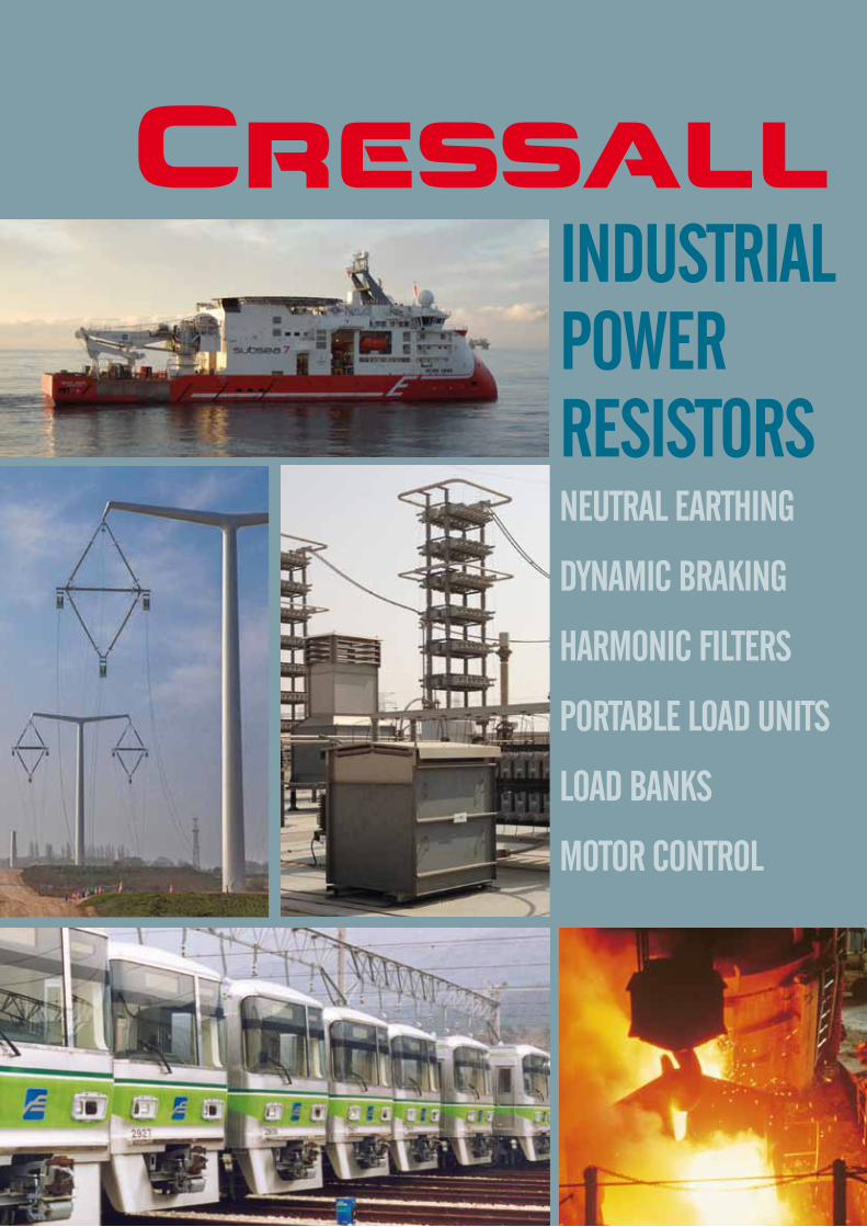
Neutral earthiNg
DyNamic BrakiNg
harmoNic Filters
PortaBle loaD uNits
loaD BaNks
motor coNtrol
iNDustrial PoWer resistors
Cressall
2
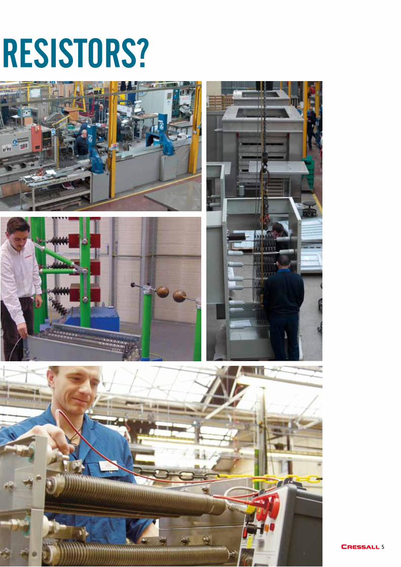
Why sPeciFy cressall
resistors?
3Cressall
Cressall built their first resistors in 1912 and, though we go back a long way, we’ve always been in forefront of resistor design and development.
From trams to high speed trains, stationary engines to nuclear power stations or warships to wind turbines we are proud to have provided industry with the resistors they need for over a hundred years. Our unrivalled experience translates into the most comprehensive resistor range in the world, using more technologies and resistor types than any other manufacturer. This means we can not only meet current needs but also anticipate future resistor requirements and provide the solutions necessary.
The designers and engineers at Cressall have been responsible for many of the important breakthroughs in resistor development including the revolutionary EV2 modular ceramic braking resistor described in this brochure.
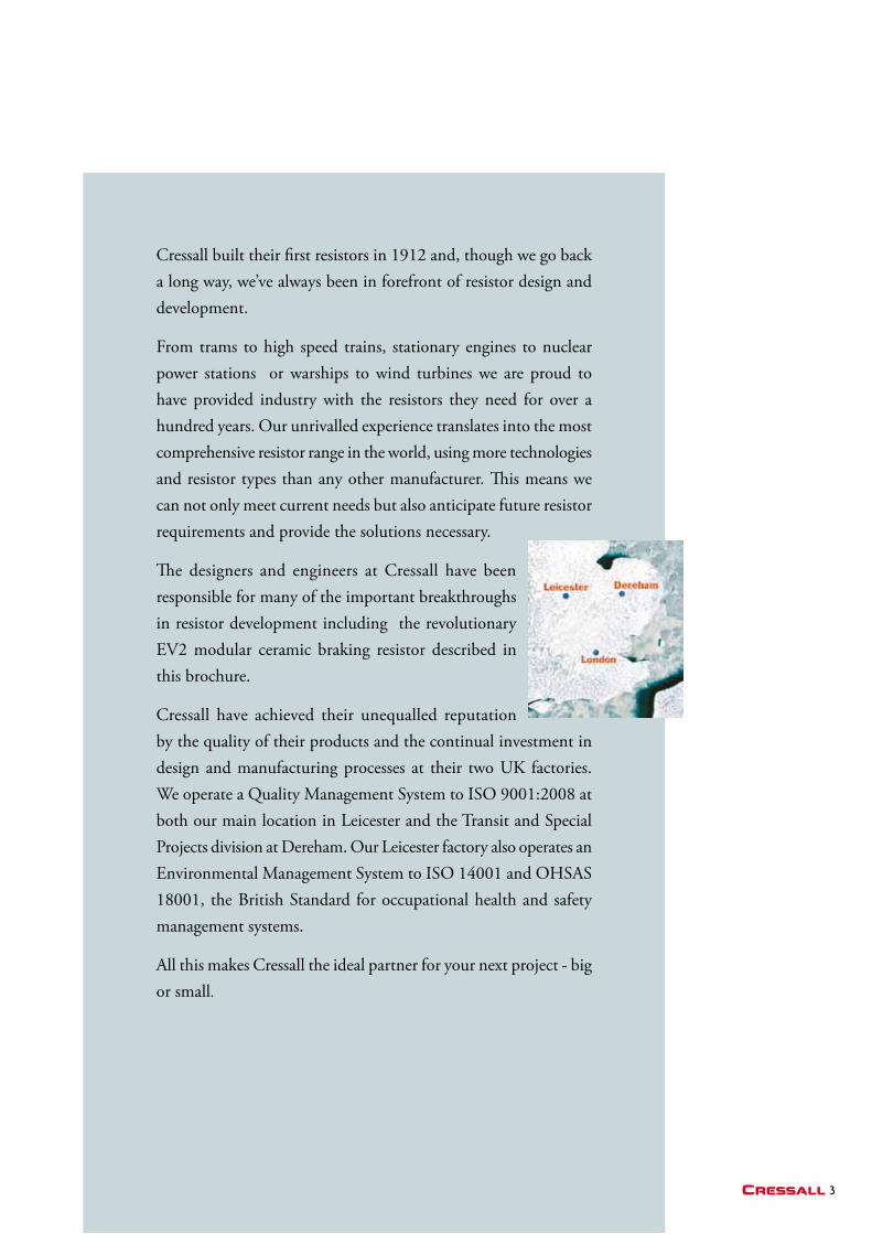
Cressall have achieved their unequalled reputation by the quality of their products and the continual investment in design and manufacturing processes at their two UK factories. We operate a Quality Management System to ISO 9001:2008 at both our main location in Leicester and the Transit and Special Projects division at Dereham. Our Leicester factory also operates an Environmental Management System to ISO 14001 and OHSAS 18001, the British Standard for occupational health and safety management systems.
All this makes Cressall the ideal partner for your next project - big or small.
4
Why sPeciFy cressall resistors?Cressall reliabilityCressall products are well-proven in the most arduous and demanding environments such as found in steel works, chemical plants and oil rigs.
Versatile technologyThe broad range of Cressall resistor elements provides the versatility required to offer solutions for any application.
Resistors can be specified for any combination of resistance value, temperature rise, duty cycle, current and voltage rating.
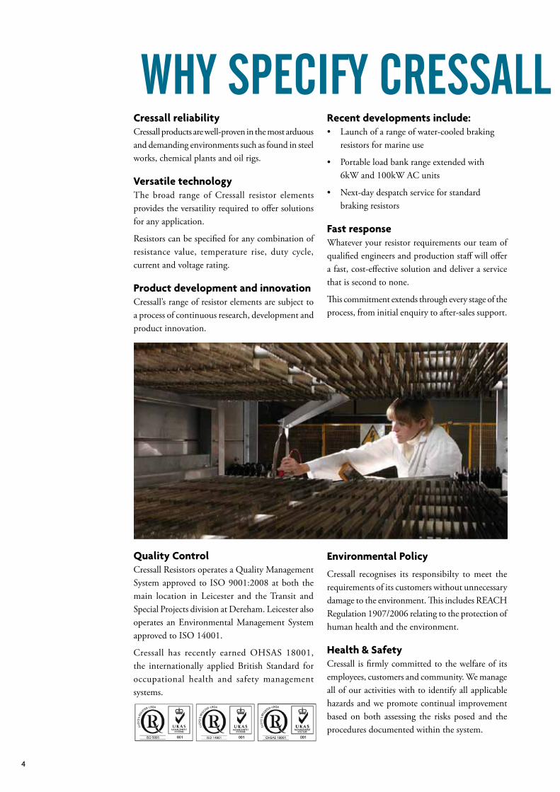
Product development and innovationCressall’s range of resistor elements are subject to a process of continuous research, development and product innovation.
Recent developments include:• Launchofarangeofwater-cooledbraking resistors for marine use
• Portableloadbankrangeextendedwith 6kW and 100kW AC units
• Next-daydespatchserviceforstandard braking resistors
Fast responseWhatever your resistor requirements our team of qualified engineers and production staff will offer a fast, cost-effective solution and deliver a service that is second to none.
This commitment extends through every stage of the process, from initial enquiry to after-sales support.
Quality ControlCressall Resistors operates a Quality Management System approved to ISO 9001:2008 at both the main location in Leicester and the Transit and Special Projects division at Dereham. Leicester also operates an Environmental Management System approved to ISO 14001.
Cressall has recently earned OHSAS 18001, the internationally applied British Standard for occupational health and safety management systems.
Environmental Policy
Cressall recognises its responsibilty to meet the requirements of its customers without unnecessary damage to the environment. This includes REACH Regulation 1907/2006 relating to the protection of human health and the environment.
Health & SafetyCressall is firmly committed to the welfare of its employees, customers and community. We manage all of our activities with to identify all applicable hazards and we promote continual improvement based on both assessing the risks posed and the procedures documented within the system.
5Cressall
Why sPeciFy cressall resistors?
6
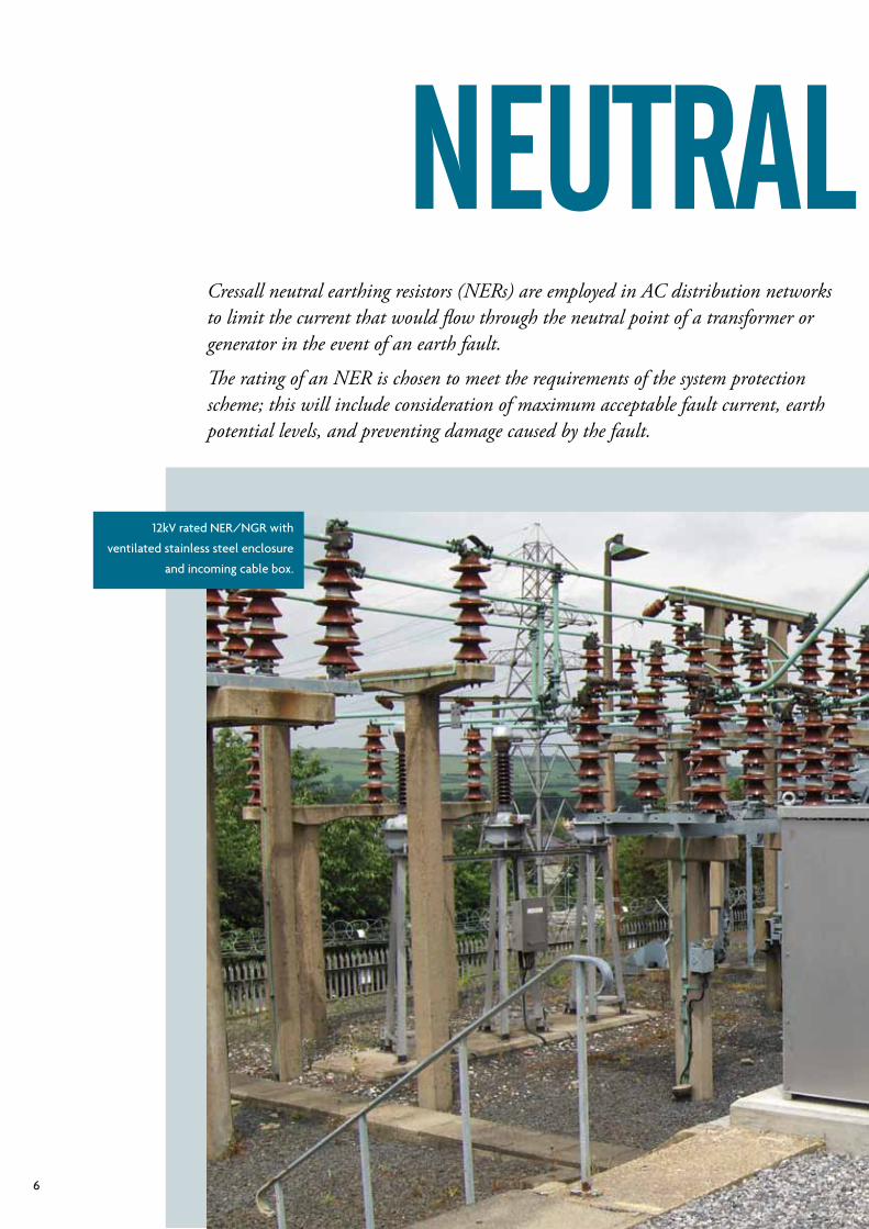
12kV rated NER/NGR with
ventilated stainless steel enclosure
and incoming cable box.
Neutral earthiNg Cressall neutral earthing resistors (NERs) are employed in AC distribution networks to limit the current that would flow through the neutral point of a transformer or generator in the event of an earth fault.
The rating of an NER is chosen to meet the requirements of the system protection scheme; this will include consideration of maximum acceptable fault current, earth potential levels, and preventing damage caused by the fault.
7Cressall
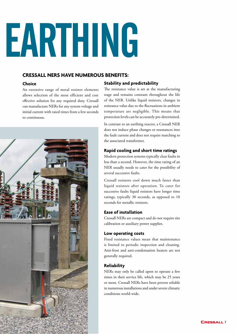
Neutral earthiNg ChoiceAn extensive range of metal resistor elements allows selection of the most efficient and cost effective solution for any required duty. Cressall canmanufactureNERsforanysystemvoltageandinitial current with rated times from a few seconds to continuous.
Stability and predictabilityThe resistance value is set at the manufacturing stage and remains constant throughout the life of theNER.Unlike liquid resistors, changes inresistance value due to the fluctuations in ambient temperature are negligible. This means that protection levels can be accurately pre-determined.
Incontrasttoanearthingreactor,aCressallNERdoes not induce phase changes or resonances into the fault current and does not require matching to the associated transformer.
Rapid cooling and short time ratingsModern protection systems typically clear faults in less than a second. However, the time rating of an NERusuallyneedstocaterforthepossibilityofseveral successive faults.
Cressall resistors cool down much faster than liquid resistors after operation. To cater for successive faults liquid resistors have longer time ratings, typically 30 seconds, as opposed to 10 seconds for metallic resistors.
Ease of installation CressallNERsarecompactanddonotrequiresitecalibration or auxiliary power supplies.
Low operating costsFixed resistance values mean that maintenance is limited to periodic inspection and cleaning. Anti-frost and anti-condensation heaters are not generally required.
ReliabilityNERsmayonlybecalledupontooperateafewtimes in their service life, which may be 25 years ormore.CressallNERshavebeenprovenreliablein numerous installations and under severe climatic conditions world-wide.
CRESSaLL NERS HaVE NumERouS bENEFitS:
8
Neutral earthiNg coNstructioNStandardsAtpresenttheonlystandardforNERsisANSI/IEEEStd32,1972.CressallNERscanbedesignedand tested to comply with this standard, or with individual client specifications.
Resistor elementsFor the majority of ratings the most suitable element is the type RP oval edge-wound coil.
RP resistors are manufactured from a continuous stainless steel strip, wound edgewise into oval coils. Each coil is supported by ridged ceramic insulators mounted on a stainless steel centre support, with stainless steel terminals welded at each end. This arrangement allows free expansion and contraction at operating temperatures up to 1100°C without imposing strain on the assembly.
The resistance alloys used are high temperature stainless steels capable of withstanding temperature excursions to 1100°C whilst retaining their strength, unlike 304 or other structural grade stainless steels which are limited to much lower temperatures.
NERsdesignedforoperationtohighertemperaturesrequire less active mass, resulting in more compact and economical designs.
temperature coefficient of resistanceUnlike structural grade stainless steels the temperature coefficient of the material used ensures a resistance increase of less than 3.5% per 100°C rise over the operating temperature range.
Resistor banksThe end insulators of individual resistor elements are clamped and locked on to tie-rods. Any element can be removed without disturbing the remainder.
The tie-rods are supported between galvanised end-plates to form banks. These banks can be mounted on top of each other with intermediate insulators to form a complete self-supporting stack.
Interconnections between coils are copper, using two bolts per joint.
Enclosure protection ratingsThe standard enclosure is designed to IP23 to IEC529 (to prevent the ingress of foreign bodies greater than 12mm, and rain falling at any angle up to 60° from the vertical). This rating is suitable for indoor or outdoor use as it allows sufficient cooling and provides more than adequate protection unless the environmental conditions are extreme. Protection ratings above IP23 are rarely needed because Cressall resistor stacks are virtually corrosion proof and immune from progressive pitting and rusting. The operation of the resistor and the ceramic insulators are not affected by exposure to condensation, sand or fine dust, provided that the dust is not unduly conductive.
If higher degrees of protection are specified, these can be provided (up to IP55). It should be realised that the operational penalty of using less well ventilated enclosures is that the external surfaces will become hotter and cooling times will be longer.
Enclosure materials and finishEnclosures are manufactured as standard from unpainted stainless steel. This ensures better and more economic long term corrosion protection than galvanised or painted mild steel units.
If required other enclosure materials and special finishes can be supplied to comply with users’ specifications.
9Cressall
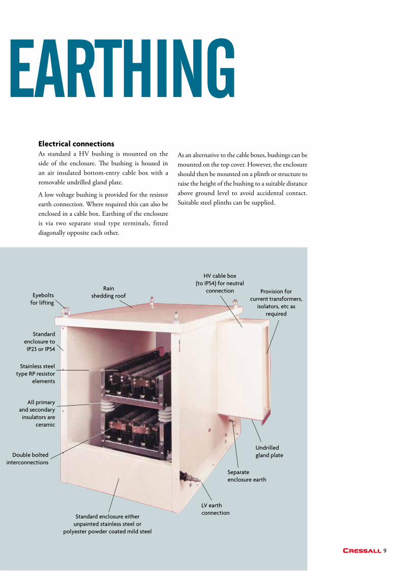
Rain shedding roofEyebolts
for lifting
HV cable box (to IP54) for neutral
connection Provision for current transformers,
isolators, etc as required
Undrilled gland plate
Separate enclosure earth
All primary and secondary
insulators are ceramic
Double bolted interconnections
Stainless steel type RP resistor
elements
Standard enclosure to IP23 or IP54
LV earth connection
Standard enclosure either unpainted stainless steel or
polyester powder coated mild steel
Neutral earthiNg Electrical connectionsAs standard a HV bushing is mounted on the side of the enclosure. The bushing is housed in an air insulated bottom-entry cable box with a removable undrilled gland plate.
A low voltage bushing is provided for the resistor earth connection. Where required this can also be enclosed in a cable box. Earthing of the enclosure is via two separate stud type terminals, fitted diagonally opposite each other.
As an alternative to the cable boxes, bushings can be mounted on the top cover. However, the enclosure should then be mounted on a plinth or structure to raise the height of the bushing to a suitable distance above ground level to avoid accidental contact. Suitable steel plinths can be supplied.
10
other equipmentWhere required cable boxes can house current transformers, isolators, vacuum contactors or other ancillary equipment.
Standard testsAsstandard,NERsaretestedtotherequirementsofANSI/IEEEStd32,1972.
Routine tests on all units include:
• Dimensionalchecktorelevantdrawing
• Resistancemeasurementatambient temperature
• Oneminutepowerfrequencywithstandtest tolevelsspecifiedinANSI/IEEEStd32, 1972 typically (2.25 x line voltage) +2kV
Temperature rise type tests have been carried out on a range of typical ratings for both 760°C (in accordancewithANSI/IEEEStd32,1972) and1000°C. Copies of these results are available.
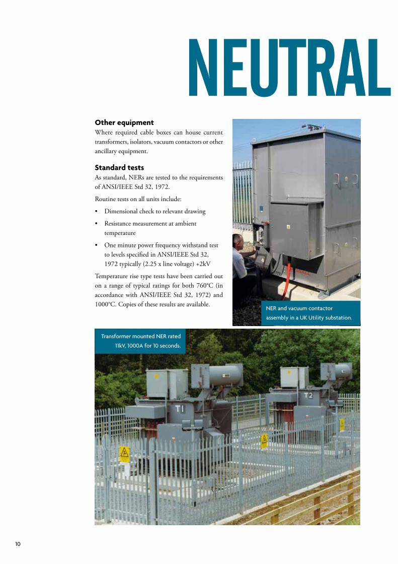
NER and vacuum contactor
assembly in a UK Utility substation.
Transformer mounted NER rated
11kV, 1000A for 10 seconds.
Neutral earthiNg
11Cressall
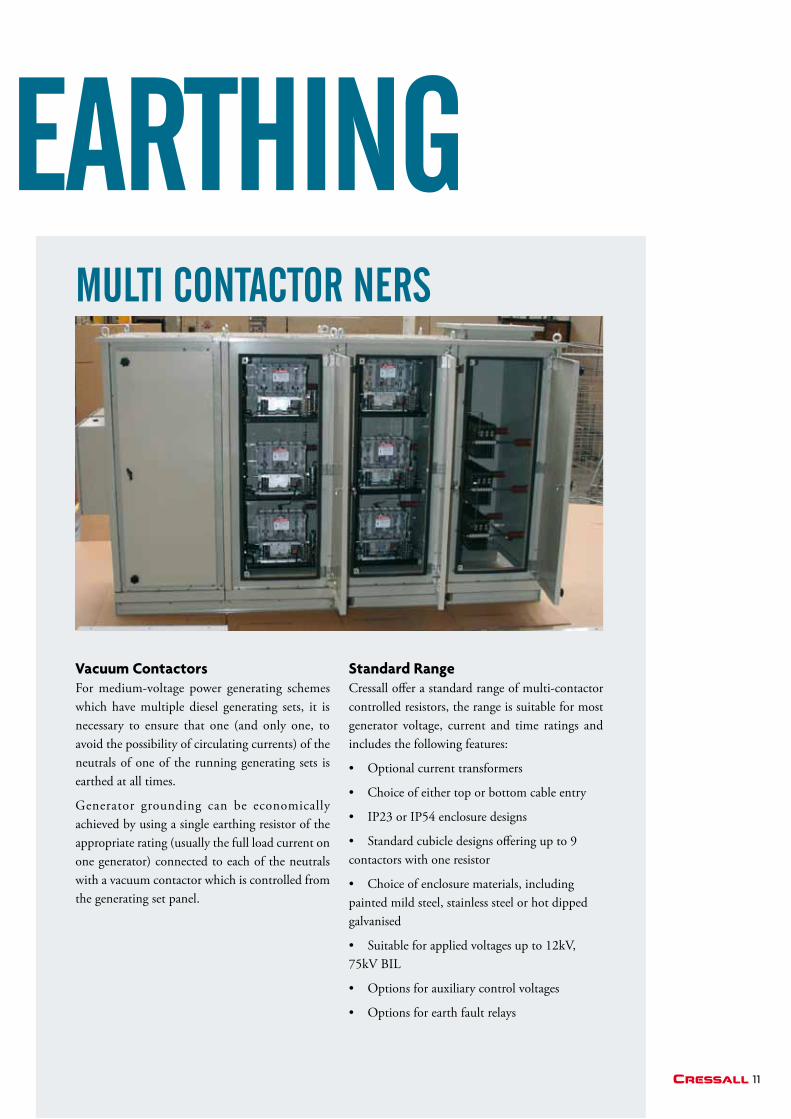
Vacuum ContactorsFor medium-voltage power generating schemes which have multiple diesel generating sets, it is necessary to ensure that one (and only one, to avoid the possibility of circulating currents) of the neutrals of one of the running generating sets is earthed at all times.
Generator grounding can be economically achieved by using a single earthing resistor of the appropriate rating (usually the full load current on one generator) connected to each of the neutrals with a vacuum contactor which is controlled from the generating set panel.
Standard RangeCressall offer a standard range of multi-contactor controlled resistors, the range is suitable for most generator voltage, current and time ratings and includes the following features:
• Optionalcurrenttransformers
• Choiceofeithertoporbottomcableentry
• IP23orIP54enclosuredesigns
• Standardcubicledesignsofferingupto9contactors with one resistor
• Choiceofenclosurematerials,includingpainted mild steel, stainless steel or hot dipped galvanised
• Suitableforappliedvoltagesupto12kV,75kV BIL
• Optionsforauxiliarycontrolvoltages
• Optionsforearthfaultrelays
multi coNtactor Ners
Neutral earthiNg
12
Cressall is one of the leading suppliers of dynamic braking resistors to OEMs, integrators, users and distributors of AC variable frequency drives.
Cressall DBRs are used to stop motors or to produce a braking torque in the motor during overhauling load conditions. The dynamic braking resistor is connected across the DC bus and can see voltages as high as 1100 volts (Cressall DBRs can be insulated and rated for higher voltages if required).
The resistance value determines the amount of braking torque produced and thus the rate at
which the motor will stop, the lower the resistance the higher the braking torque and the quicker the stop. Drive manufacturers will specify a minimum resistance value to ensure that the braking capacity of the drive is not exceeded. As standard Cressall manufacture DBRs with a –0/+10% tolerance to ensure optimum performance (other values can be achieved if required).
When sizing brake resistors, key parameters for consideration are resistance value, braking power and the duration and frequency of the stop.
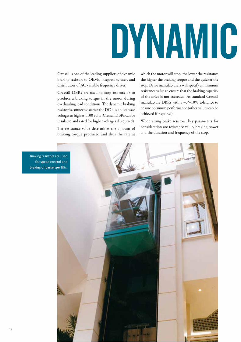
Braking resistors are used
for speed control and
braking of passenger lifts.
DyNamic BrakiNg
13Cressall
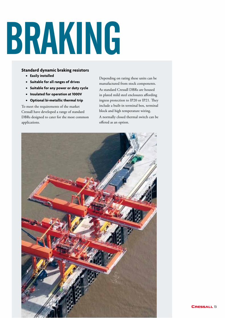
DyNamic BrakiNgStandard dynamic braking resistors • Easily installed
• Suitable for all ranges of drives
• Suitable for any power or duty cycle
• insulated for operation at 1000V
• optional bi-metallic thermal trip
To meet the requirements of the market Cressall have developed a range of standard DBRs designed to cater for the most common applications.
Depending on rating these units can be manufactured from stock components.
As standard Cressall DBRs are housed in plated mild steel enclosures affording ingress protection to IP20 or IP21. They include a built-in terminal box, terminal block and high temperature wiring.
A normally closed thermal switch can be offered as an option.
14
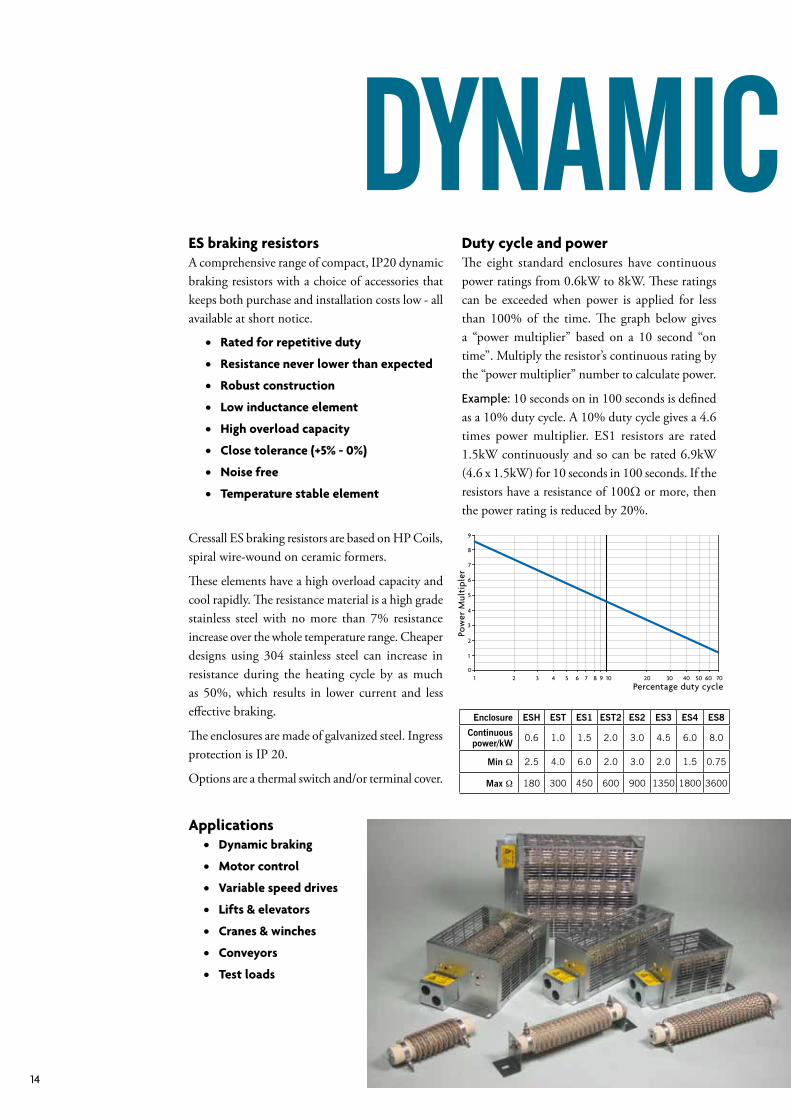
• Rated for repetitive duty
• Resistance never lower than expected
• Robust construction
• Low inductance element
• High overload capacity
• Close tolerance (+5% - 0%)
• Noise free
• temperature stable element
Cressall ES braking resistors are based on HP Coils, spiral wire-wound on ceramic formers.
These elements have a high overload capacity and cool rapidly. The resistance material is a high grade stainless steel with no more than 7% resistance increase over the whole temperature range. Cheaper designs using 304 stainless steel can increase in resistance during the heating cycle by as much as 50%, which results in lower current and less effective braking.
The enclosures are made of galvanized steel. Ingress protection is IP 20.
Options are a thermal switch and/or terminal cover.
applications • Dynamic braking
• motor control
• Variable speed drives
• Lifts & elevators • Cranes & winches
• Conveyors
• test loads
ES braking resistorsA comprehensive range of compact, IP20 dynamic braking resistors with a choice of accessories that keeps both purchase and installation costs low - all available at short notice.
Enclosure ESH EST ES1 EST2 ES2 ES3 ES4 ES8
Continuous power/kW 0.6 1.0 1.5 2.0 3.0 4.5 6.0 8.0
Min Ω 2.5 4.0 6.0 2.0 3.0 2.0 1.5 0.75
Max Ω 180 300 450 600 900 1350 1800 3600
Duty cycle and powerThe eight standard enclosures have continuous power ratings from 0.6kW to 8kW. These ratings can be exceeded when power is applied for less than 100% of the time. The graph below gives a “power multiplier” based on a 10 second “on time”. Multiply the resistor’s continuous rating by the “power multiplier” number to calculate power.
Example: 10 seconds on in 100 seconds is defined as a 10% duty cycle. A 10% duty cycle gives a 4.6 times power multiplier. ES1 resistors are rated 1.5kW continuously and so can be rated 6.9kW (4.6 x 1.5kW) for 10 seconds in 100 seconds. If the resistors have a resistance of 100Ω or more, then the power rating is reduced by 20%.
1 2 3 4 5 6 7 8 9 10 20 30 40 50 60 70
9
8
7
6
5
4
3
2
1
0
Pow
er M
ulti
pler
Percentage duty cycle
DyNamic BrakiNg
15Cressall
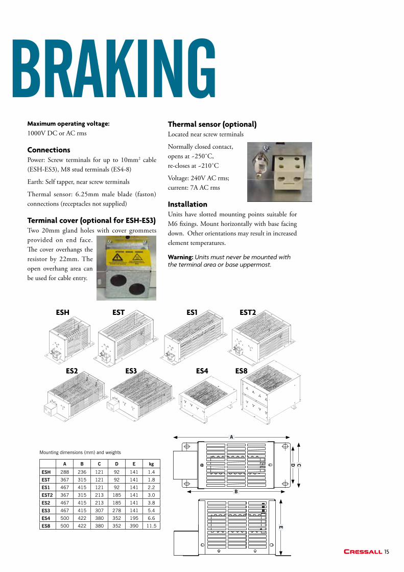
maximum operating voltage: 1000V DC or AC rms
ConnectionsPower: Screw terminals for up to 10mm2 cable (ESH-ES3), M8 stud terminals (ES4-8)
Earth: Self tapper, near screw terminals
Thermal sensor: 6.25mm male blade (faston) connections (receptacles not supplied)
terminal cover (optional for ESH-ES3) Two 20mm gland holes with cover grommets provided on end face. The cover overhangs the resistor by 22mm. The open overhang area can be used for cable entry.
thermal sensor (optional)Located near screw terminals
Normallyclosedcontact,opens at ~250˚C, re-closes at ~210˚C
Voltage: 240V AC rms; current: 7A AC rms
installationUnits have slotted mounting points suitable for M6 fixings. Mount horizontally with base facing down. Other orientations may result in increased element temperatures.
Warning: Units must never be mounted with the terminal area or base uppermost.
E
ESH ES1
ES2 ES3
ESt ESt2
ES4 ES8
Mounting dimensions (mm) and weights
A B C D E kg
ESH 288 236 121 92 141 1.4
EST 367 315 121 92 141 1.8
ES1 467 415 121 92 141 2.2
EST2 367 315 213 185 141 3.0
ES2 467 415 213 185 141 3.8
ES3 467 415 307 278 141 5.4
ES4 500 422 380 352 195 6.6
ES8 500 422 380 352 390 11.5
A
B
D C
DyNamic BrakiNg
16
advantages of electric brakingUsing an electric drive means that reliable systems of regenerative and dynamic braking can complement or replace traditional mechanical braking systems. The advantages of electric braking include control, reliability, mechanical simplicity, weight saving and the opportunity to make use of the regenerated braking energy making fuel savings when compared with older mechanical systems.
Cressall Resistors’ long experience in this field means that we have suitable brake resistor designs for all of the above applications, with braking powers from a few kW up to many MW (needed, for example, for some crane and main propulsion brakes) and cooling methods which include liquid, forced air and natural convection. We have standard products of all types.
Design considerationsDepending on rating many of our designs use elements manufactured from a high grade resistance alloy in sheathed mineral insulated tubes. These are less vulnerable to physical damage, prevent accidental contact with live, possibly high, voltages, and are thus much safer. For heavily polluted areas, or in areas where there is risk of exposure to flammable liquids or gases, or in severely corrosive environments sheathed element would also be used. Marine-grade stainless steel for all metalwork including fasteners and fittings is standard.
For brake resistors operating at more than 1.5kV, sheathed elements are unsuitable and we use live elements. Cooling is usually by natural convection, but if the heat losses after braking would impose unacceptable loads on the ship’s air conditioning system we can add an air-to-water heat exchanger to transfer the brake energy to the ship’s chilled water system.
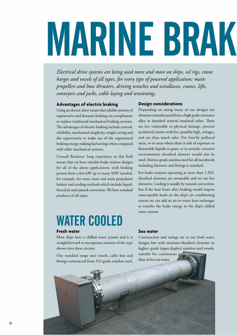
Water cooleDFresh waterMost ships have a chilled water system and it is straightforward to incorporate resistors of the type shown into these circuits.
Our standard range uses vessels, cable box and fittings constructed from 316 grade stainless steel.
Sea waterConstruction and ratings are as our fresh water designs but with titanium-sheathed elements in higher- grade (super duplex) stainless steel vessels, suitable for continuous duty in hot sea water.
Electrical drive systems are being used more and more on ships, oil rigs, crane barges and vessels of all types, for every type of powered application: main propellers and bow thrusters, driving winches and windlasses, cranes, lifts, conveyors and jacks, cable laying and tensioning..
mariNe BrakiNg
17Cressall
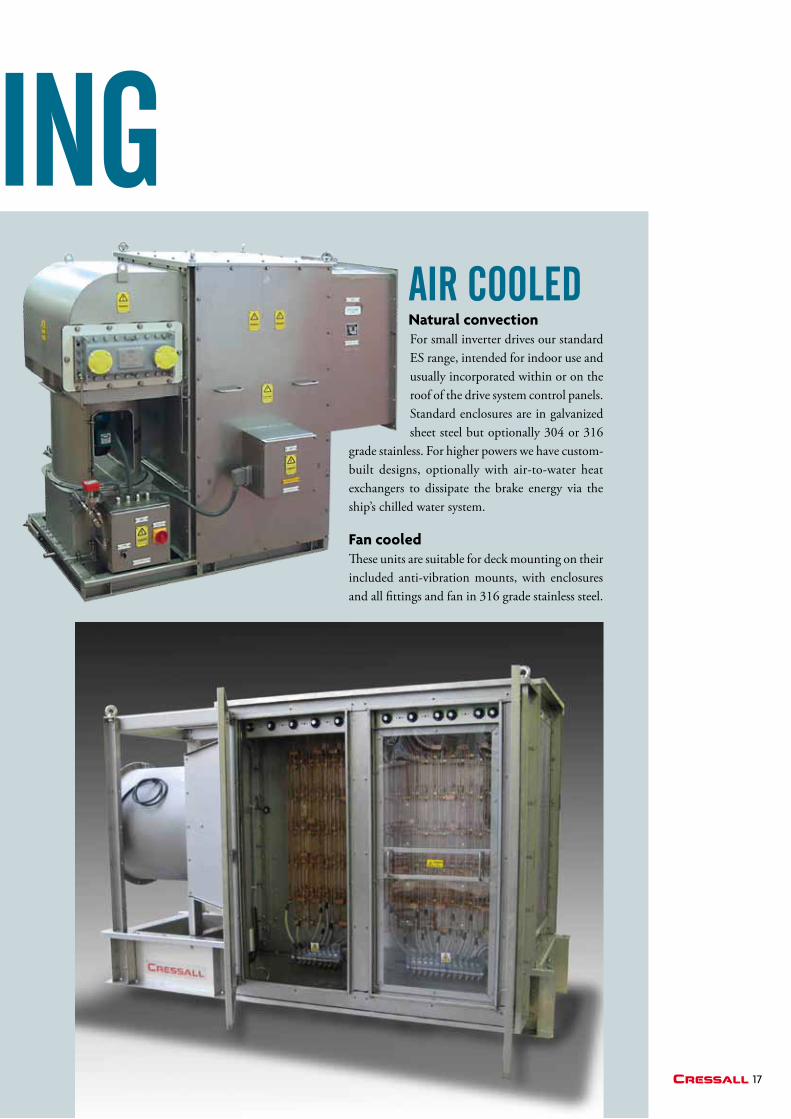
air cooleDNatural convectionFor small inverter drives our standard ES range, intended for indoor use and usually incorporated within or on the roof of the drive system control panels. Standard enclosures are in galvanized sheet steel but optionally 304 or 316
grade stainless. For higher powers we have custom-built designs, optionally with air-to-water heat exchangers to dissipate the brake energy via the ship’s chilled water system.
Fan cooled These units are suitable for deck mounting on their included anti-vibration mounts, with enclosures and all fittings and fan in 316 grade stainless steel.
mariNe BrakiNg
18
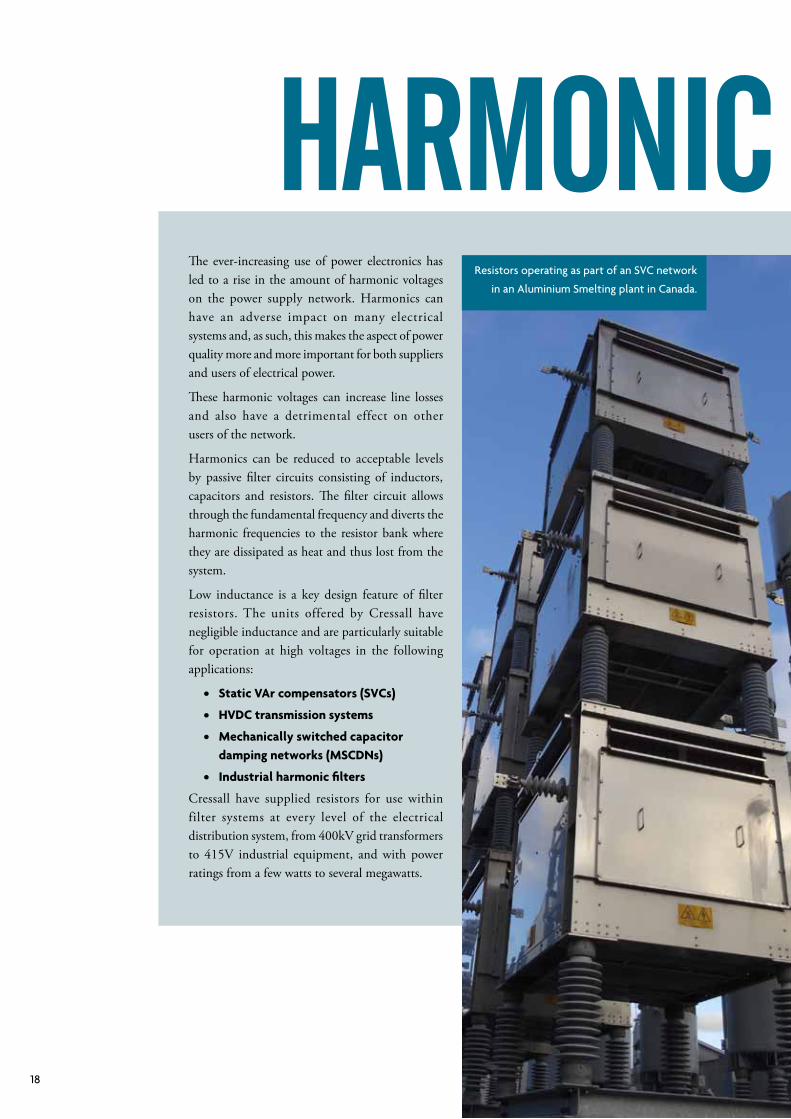
harmoNic FiltersResistors operating as part of an SVC network
in an Aluminium Smelting plant in Canada.
The ever-increasing use of power electronics has led to a rise in the amount of harmonic voltages on the power supply network. Harmonics can have an adverse impact on many electrical systems and, as such, this makes the aspect of power quality more and more important for both suppliers and users of electrical power.
These harmonic voltages can increase line losses and also have a detrimental effect on other users of the network.
Harmonics can be reduced to acceptable levels by passive filter circuits consisting of inductors, capacitors and resistors. The filter circuit allows through the fundamental frequency and diverts the harmonic frequencies to the resistor bank where they are dissipated as heat and thus lost from the system.
Low inductance is a key design feature of filter resistors. The units offered by Cressall have negligible inductance and are particularly suitable for operation at high voltages in the following applications:
• Static Var compensators (SVCs)
• HVDC transmission systems
• mechanically switched capacitor damping networks (mSCDNs)
• industrial harmonic filters
Cressall have supplied resistors for use within filter systems at every level of the electrical distribution system, from 400kV grid transformers to 415V industrial equipment, and with power ratings from a few watts to several megawatts.
19Cressall
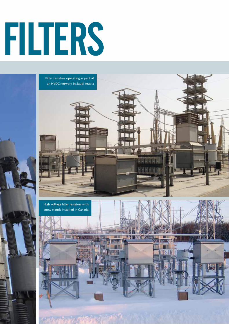
harmoNic FiltersFilter resistors operating as part of
an HVDC network in Saudi Arabia
High voltage filter resistors with
snow stands installed in Canada
20
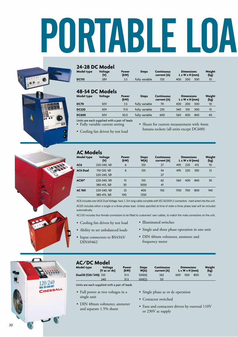
24-28 DC modelmodel type Voltage Power Steps Continuous Dimensions Weight (V) (kW) current (a) L x W x H (mm) (kg)DC110 28V 3.3 fully variable 120 400 200 500 10
48-54 DC modelsmodel type Voltage Power Steps Continuous Dimensions Weight (kW) current (a) L x W x H (mm) (kg)DC70 50V 3.5 fully variable 70 400 200 500 10
DC220 50V 11.0 fully variable 210 540 310 500 15
DC600 50V 30.0 fully variable 600 560 400 840 40
Units are each supplied with a pair of leads
aC modelsmodel type Voltage Power Steps Continuous Dimensions Weight (V) (kW) W(a) current (a) L x W x H (mm) (kg)aC6 220-240, 1Ø 6 333 27 495 220 415 10
aC6 Dual 110-120, 1Ø 6 333 54 495 220 550 12 220-240, 1Ø 27
aC30* 220-240, 1Ø 15 333 62 560 400 840 30 380-415, 3Ø 30 1000 41
aC 100 220-240, 1Ø 33 400 150 1150 700 800 140 380-415, 3Ø 100 1250
PortaBle loaD BaNks
• Fully variable current setting
• Cooling fan driven by test load
• Full power at two voltages in a single unit
• DIN48mmvoltmeter,ammeterand separate 1.5% shunt
• Cooling fan driven by test load
• Ability to set unbalanced loads
• Input connectors to BS4343/DIN49462
• Single phase ac or dc operation
• Contactor switched
• Fans and contactors driven by external 110V or 230V ac supply
aC/DC modelmodel type Voltage Power Steps Continuous Dimensions Weight (V ac or dc) (kW) W(a) current (a) L x W x H (mm) (kg)Dual30 (120/240) 120 31.5 500(4) 262 600 500 800 50 240 31.5 500(2) 131
Units are each supplied with a pair of leads
• Shunt for current measurement with 4mm banana sockets (all units except DC600)
AC6 includes one (AC6 Dual Voltage: two) 1.5m long cable complete with IEC 60309-2 connectors - hard wired into the unit.
AC30 includes either a single or a three phase lead. Unless specified at time of order a three phase lead will be included automatically.
AC100 includes four female connectors to be fitted to customers’ own cables, to match the male connectors on the unit.
• Illuminated switches
• Single and three phase operation in one unit
• DIN48mmvoltmeter,ammeterandfrequency meter
21Cressall
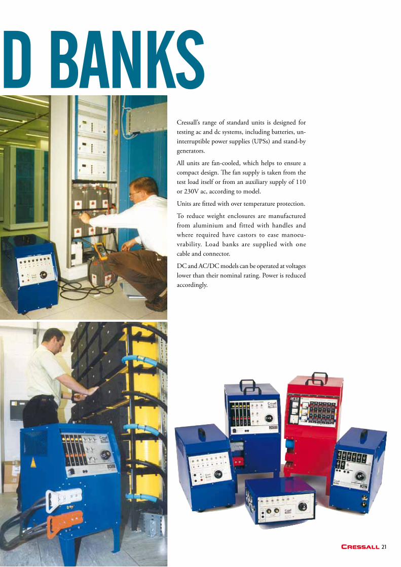
PortaBle loaD BaNks Cressall’s range of standard units is designed for testing ac and dc systems, including batteries, un-interruptible power supplies (UPSs) and stand-by generators.
All units are fan-cooled, which helps to ensure a compact design. The fan supply is taken from the test load itself or from an auxiliary supply of 110 or 230V ac, according to model.
Units are fitted with over temperature protection.
To reduce weight enclosures are manufactured from aluminium and fitted with handles and where required have castors to ease manoeu-vrability. Load banks are supplied with one cable and connector.
DC and AC/DC models can be operated at voltages lower than their nominal rating. Power is reduced accordingly.
22
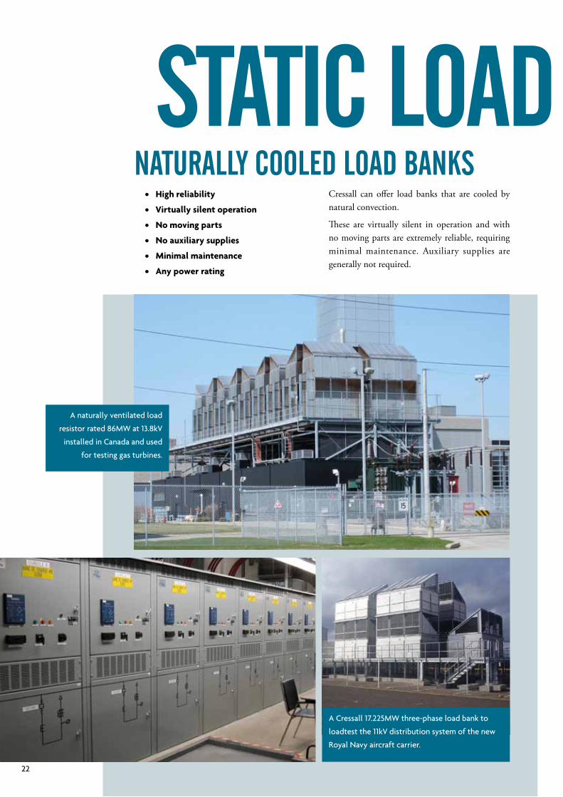
A Cressall 17.225MW three-phase load bank to
loadtest the 11kV distribution system of the new
Royal Navy aircraft carrier.
A naturally ventilated load
resistor rated 86MW at 13.8kV
installed in Canada and used
for testing gas turbines.
Cressall can offer load banks that are cooled by natural convection.
These are virtually silent in operation and with no moving parts are extremely reliable, requiring minimal maintenance. Auxiliary supplies are generally not required.
• High reliability
• Virtually silent operation
• No moving parts
• No auxiliary supplies
• minimal maintenance
• any power rating
Naturally cooleD loaD BaNks
static loaD BaNks
23Cressall
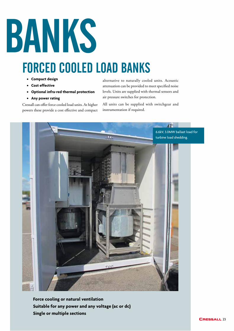
6.6kV, 3.0MW ballast load for
turbine load shedding.
• Compact design
• Cost effective
• optional infra-red thermal protection
• any power rating
Cressall can offer force cooled load units. At higher powers these provide a cost effective and compact
alternative to naturally cooled units. Acoustic attenuation can be provided to meet specified noise levels. Units are supplied with thermal sensors and air pressure switches for protection.
All units can be supplied with switchgear and instrumentation if required.
Force cooling or natural ventilation
Suitable for any power and any voltage (ac or dc)
Single or multiple sections
ForceD cooleD loaD BaNks
static loaD BaNks
24
The increasing importance of sustainable, low carbon power generation means
that electrical engineers have to be able to confidently specify components and
equipment that have been developed for use in such applications.
Cressall has made significant investment in the design and manufacture of resistors
for the testing, generation and control of renewable energy:
Pre-Insertion Resistors
Crowbar Resistors
Neutral Earthing Resistors
Dynamic Braking Resistors
Load test
Resistors for Static VAR Compensators
reNeWaBle eNergy
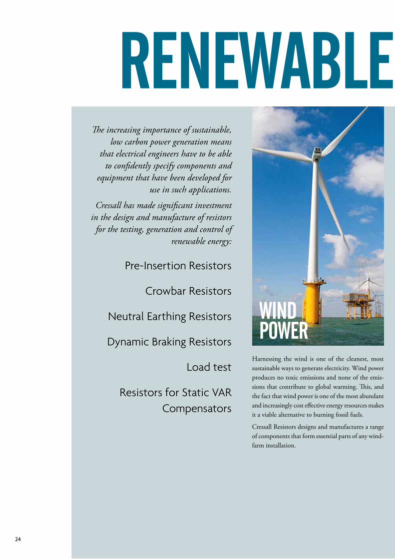
WiND PoWer
Harnessing the wind is one of the cleanest, most sustainable ways to generate electricity. Wind power produces no toxic emissions and none of the emis-sions that contribute to global warming. This, and the fact that wind power is one of the most abundant and increasingly cost effective energy resources makes it a viable alternative to burning fossil fuels.
Cressall Resistors designs and manufactures a range of components that form essential parts of any wind-farm installation.
25Cressall
reNeWaBle eNergy
solar PoWer
Wave & tiDal PoWer
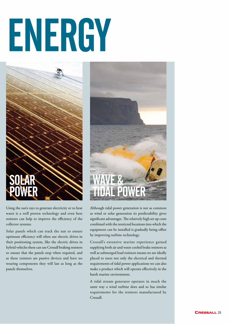
Using the sun’s rays to generate electricity or to heat water is a well proven technology and even here resistors can help to improve the efficiency of the collector systems.
Solar panels which can track the sun to ensure optimum efficiency will often use electric drives in their positioning system, like the electric drives in hybrid vehicles these can use Cressall braking resistors to ensure that the panels stop when required, and as these resistors are passive devices and have no wearing components they will last as long as the panels themselves.
Although tidal power generation is not as common as wind or solar generation its predictability gives significant advantages. The relatively high set up costs combined with the restricted locations into which the equipment can be installed is gradually being offset by improving turbine technology.
Cressall’s extensive marine experience gained supplying both air and water cooled brake resistors as well as submerged load resistors means we are ideally placed to meet not only the electrical and thermal requirements of tidal power applications we can also make a product which will operate effectively in the harsh marine environment.
A tidal stream generator operates in much the same way a wind turbine does and so has similar requirements for the resistors manufactured by Cressall.
26
tech
Nolo
gies
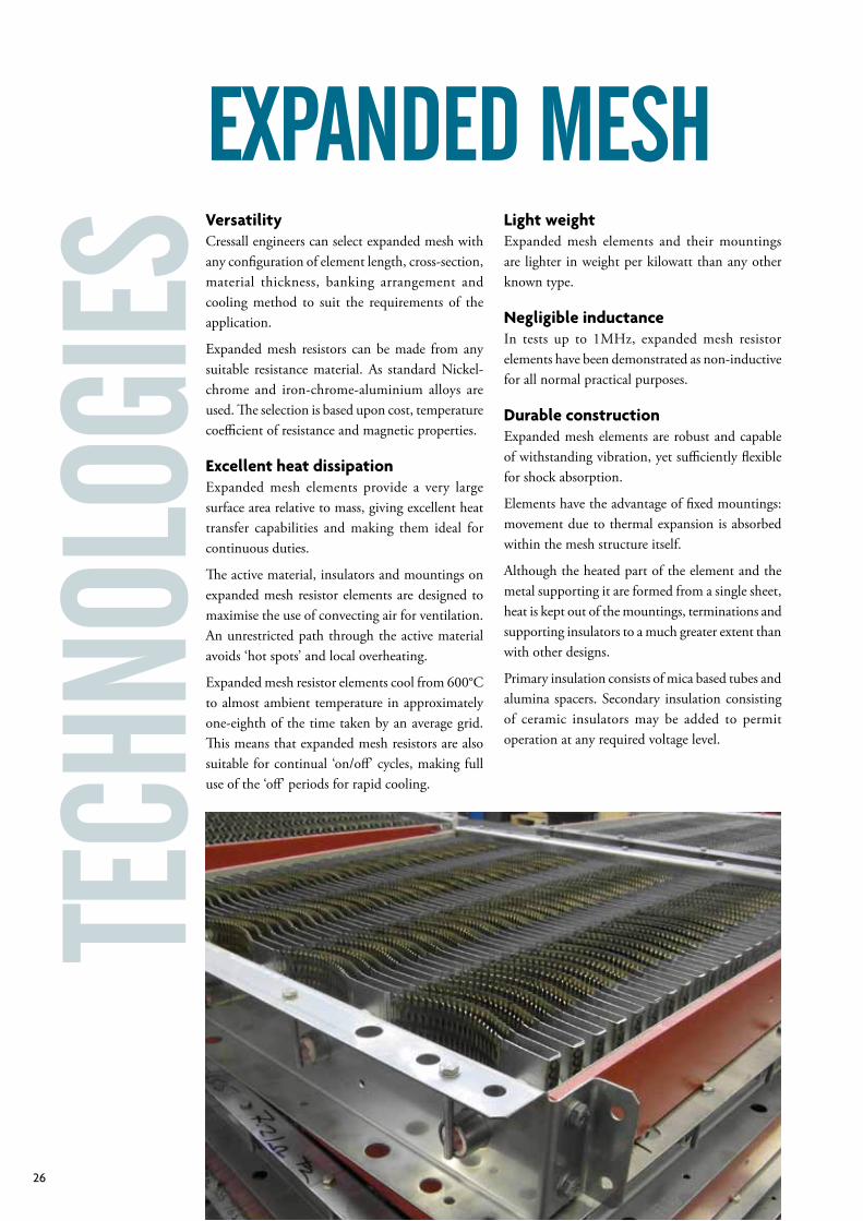
VersatilityCressall engineers can select expanded mesh with any configuration of element length, cross-section, material thickness, banking arrangement and cooling method to suit the requirements of the application.
Expanded mesh resistors can be made from any suitable resistancematerial.As standardNickel-chrome and iron-chrome-aluminium alloys are used. The selection is based upon cost, temperature coefficient of resistance and magnetic properties.
Excellent heat dissipationExpanded mesh elements provide a very large surface area relative to mass, giving excellent heat transfer capabilities and making them ideal for continuous duties.
The active material, insulators and mountings on expanded mesh resistor elements are designed to maximise the use of convecting air for ventilation. An unrestricted path through the active material avoids ‘hot spots’ and local overheating.
Expanded mesh resistor elements cool from 600°C to almost ambient temperature in approximately one-eighth of the time taken by an average grid. This means that expanded mesh resistors are also suitable for continual ‘on/off’ cycles, making full use of the ‘off’ periods for rapid cooling.
Light weightExpanded mesh elements and their mountings are lighter in weight per kilowatt than any other known type.
Negligible inductanceIn tests up to 1MHz, expanded mesh resistor elements have been demonstrated as non-inductive for all normal practical purposes.
Durable constructionExpanded mesh elements are robust and capable of withstanding vibration, yet sufficiently flexible for shock absorption.
Elements have the advantage of fixed mountings: movement due to thermal expansion is absorbed within the mesh structure itself.
Although the heated part of the element and the metal supporting it are formed from a single sheet, heat is kept out of the mountings, terminations and supporting insulators to a much greater extent than with other designs.
Primary insulation consists of mica based tubes and alumina spacers. Secondary insulation consisting of ceramic insulators may be added to permit operation at any required voltage level.
eXPaNDeD mesh
27Cressall
Cressall offer a range of standard resistor elements which can be supplied loose, in banked assemblies or in full enclosures.
• Versatile and robust
• Good heat dissipation
• High overload capacity
• Standard coil sizes
• Standard banking designs
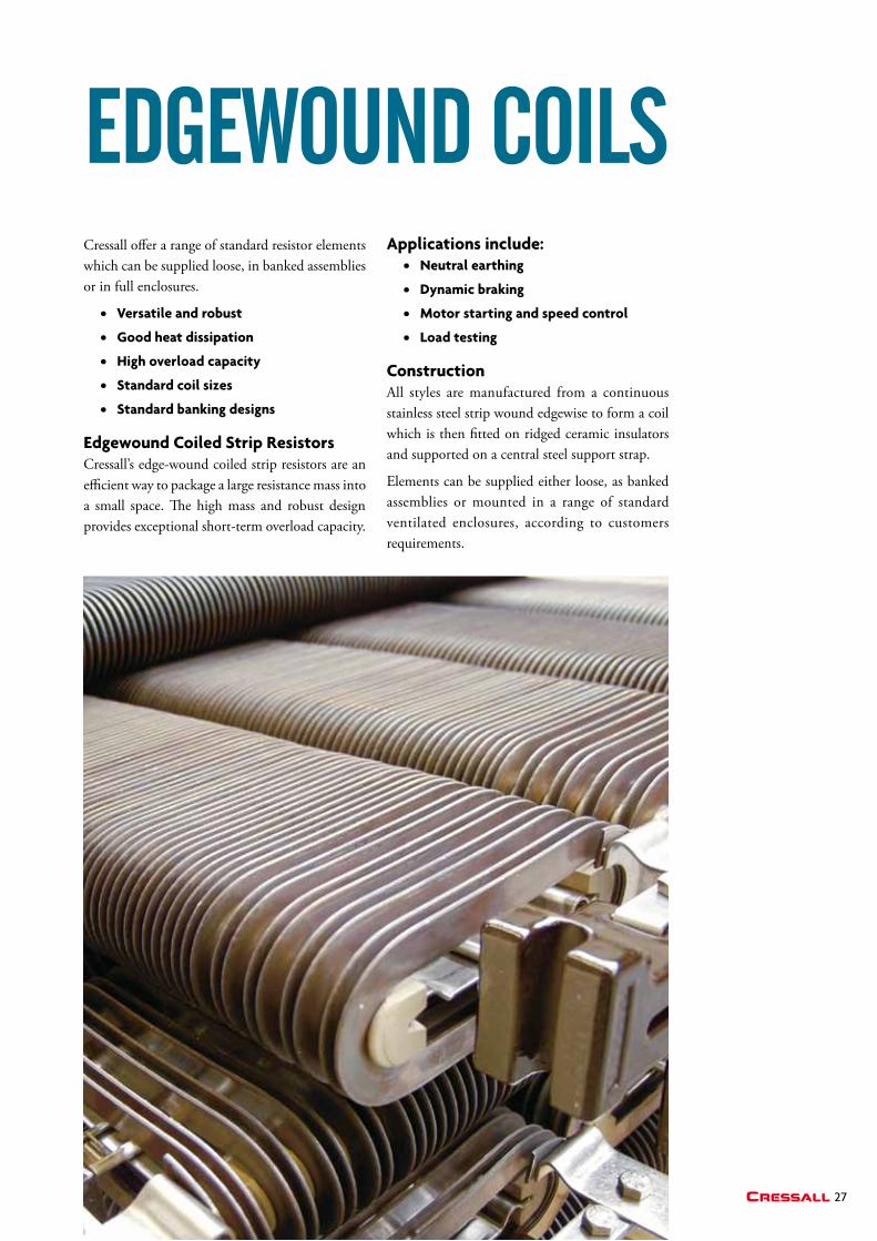
Edgewound Coiled Strip ResistorsCressall’s edge-wound coiled strip resistors are an efficient way to package a large resistance mass into a small space. The high mass and robust design provides exceptional short-term overload capacity.
eDgeWouND coilsapplications include: • Neutral earthing
• Dynamic braking
• motor starting and speed control
• Load testing
ConstructionAll styles are manufactured from a continuous stainless steel strip wound edgewise to form a coil which is then fitted on ridged ceramic insulators and supported on a central steel support strap.
Elements can be supplied either loose, as banked assemblies or mounted in a range of standard ventilated enclosures, according to customers requirements.
28
tech
Nolo
gies
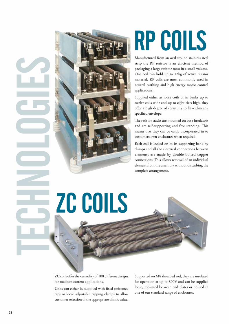
ZC coils offer the versatility of 108 different designs for medium current applications.
Units can either be supplied with fixed resistance taps or loose adjustable tapping clamps to allow customer selection of the appropriate ohmic value.
Zc coils
rP coilsManufactured from an oval wound stainless steel strip the RP resistor is an efficient method of packaging a large resistor mass in a small volume. One coil can hold up to 12kg of active resistor material. RP coils are most commonly used in neutral earthing and high energy motor control applications.
Supplied either as loose coils or in banks up to twelve coils wide and up to eight tiers high, they offer a high degree of versatility to fit within any specified envelope.
The resistor stacks are mounted on base insulators and are self-supporting and free standing. This means that they can be easily incorporated in to customers own enclosures when required.
Each coil is locked on to its supporting bank by clamps and all the electrical connections between elements are made by double bolted copper connections. This allows removal of an individual element from the assembly without disturbing the complete arrangement.
Supported on M8 threaded rod, they are insulated for operation at up to 800V and can be supplied loose, mounted between end plates or housed in one of our standard range of enclosures.
29Cressall
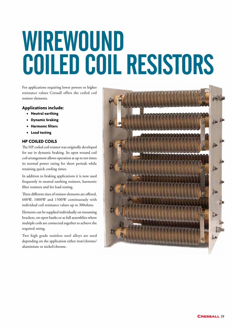
For applications requiring lower powers or higher resistance values Cressall offers the coiled coil resistor elements.
applications include: • Neutral earthing
• Dynamic braking
• Harmonic filters
• Load testing
HP CoiLED CoiLSThe HP coiled coil resistor was originally developed for use in dynamic braking. Its open wound coil coil arrangement allows operation at up to ten times its normal power rating for short periods while retaining quick cooling times.
In addition to braking applications it is now used frequently in neutral earthing resistors, harmonic filter resistors and for load testing.
Three different sizes of resistor elements are offered, 600W, 1000W and 1500W continuously with individual coil resistance values up to 300ohms.
Elements can be supplied individually on mounting brackets, on open banks or as full assemblies where multiple coils are connected together to achieve the required rating.
Two high grade stainless steel alloys are used depending on the application either iron/chrome/aluminium or nickel/chrome.
WireWouND coileD coil resistors
30
griD
res
istor
s
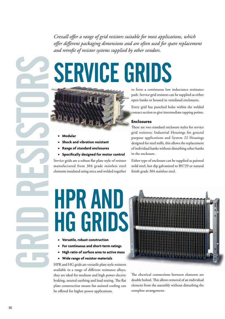
• modular
• Shock and vibration resistant
• Range of standard enclosures
• Specifically designed for motor control
Service grids are a robust flat plate style of resistor manufactured from 304 grade stainless steel elements insulated using mica and welded together
service griDs
Cressall offer a range of grid resistors suitable for most applications, which offer different packaging dimensions and are often used for spare replacement and retrofit of resistor systems supplied by other vendors.
hPr aND hg griDs • Versatile, robust construction
• For continuous and short-term ratings
• High ratio of surface area to active mass
• Wide range of resistor materials
HPR and HG grids are versatile plate style resistors available in a range of different resistance alloys, they are ideal for medium and high power electric braking, neutral earthing and load testing. The flat plate construction means fan assisted cooling can be offered for higher power applications.
to form a continuous low inductance resistance path. Service grid resistors can be supplied as either open banks or housed in ventilated enclosures.
Every grid has punched holes within the welded contact section to give intermediate tapping points.
EnclosuresThere are two standard enclosure styles for service grid resistors; Industrial Housings for general purpose applications and System 22 Housings designed for steel mills, this allows the replacement of individual banks without disturbing other banks in the enclosure.
Either type of enclosure can be supplied as painted mild steel, hot dip galvanized to BS729 or natural finish grade 304 stainless steel.
The electrical connections between elements are double bolted. This allows removal of an individual element from the assembly without disturbing the complete arrangement.
31Cressall
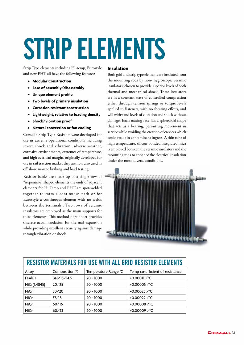
Strip Type elements including Hi-temp, Eurostyle and new EHT all have the following features:
• modular Construction
• Ease of assembly/disassembly
• unique element profile
• two levels of primary insulation
• Corrosion resistant construction
• Lightweight, relative to loading density
• Shock/vibration proof
• Natural convection or fan cooling
Cressall’s Strip Type Resistors were developed for use in extreme operational conditions including severe shock and vibration, adverse weather, corrosive environments, extremes of temperature, and high overload margin, originally developed for use in rail traction market they are now also used in off shore marine braking and load testing.
Resistor banks are made up of a single row of “serpentine” shaped elements the ends of adjacent elements for Hi Temp and EHT are spot-welded together to form a continuous path or for Eurostyle a continuous element with no welds between the terminals.. Two rows of ceramic insulators are employed as the main supports for these elements. This method of support provides discrete accommodation for thermal expansion while providing excellent security against damage through vibration or shock.
insulation Both grid and strip type elements are insulated from the mounting rods by non- hygroscopic ceramic insulators, chosen to provide superior levels of both thermal and mechanical shock. These insulators are in a constant state of controlled compression either through tension springs or torque levels applied to fasteners, with no shearing effects, and will withstand levels of vibration and shock without damage. Each mating face has a spheroidal shape that acts as a bearing, permitting movement in service while avoiding the creation of crevices which could result in contaminant ingress. A thin tube of high temperature, silicon-bonded integrated mica is employed between the ceramic insulators and the mounting rods to enhance the electrical insulation under the most adverse conditions.
striP elemeNts
resistor materials For use With all griD resistor elemeNtsAlloy Composition % Temperature Range °C Temp co-efficient of resistance
FeAlCr Bal/15/14.5 20 - 1000 +0.00011 /°C
NiCr(1.4845) 20/25 20 - 1000 +0.00005 /°C
NiCr 30/20 20 - 1000 +0.00025 /°C
NiCr 37/18 20 - 1000 +0.00022 /°C
NiCr 60/16 20 - 1000 +0.00008 /°C
NiCr 60/23 20 - 1000 +0.00009 /°C
32
tech
Nolo
gies
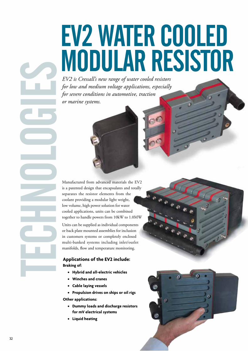
ev2 Water cooleD moDular resistor
applications of the EV2 include:braking of:
• Hybrid and all-electric vehicles
• Winches and cranes
• Cable laying vessels
• Propulsion drives on ships or oil rigs
other applications:
• Dummy loads and discharge resistors for mV electrical systems
• Liquid heating
Manufactured from advanced materials the EV2 is a patented design that encapsulates and totally separates the resistor elements from the coolant providing a modular light weight, low volume, high power solution for water cooled applications, units can be combined together to handle powers from 10kW to 1.0MW
Units can be supplied as individual components or back plate mounted assemblies for inclusion in customers systems or completely enclosed multi-banked systems including inlet/outlet manifolds, flow and temperature monitoring.
EV2 is Cressall’s new range of water cooled resistors for low and medium voltage applications, especially for severe conditions in automotive, traction or marine systems.
33Cressall
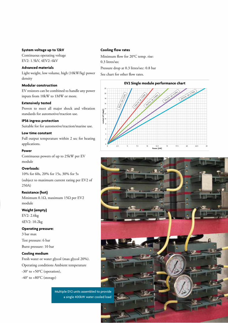
System voltage up to 12kVContinuous operating voltage EV2: 1.5kV, 4EV2: 6kV
advanced materialsLight weight, low volume, high (10kW/kg) power density
modular constructionEV resistors can be combined to handle any power inputs from 10kW to 1MW or more.
Extensively testedProven to meet all major shock and vibration standards for automotive/traction use.
iP56 ingress protectionSuitable for for automotive/traction/marine use.
Low time constantFull output temperature within 2 sec for heating applications.
PowerContinuous powers of up to 25kW per EV module
overloads:10% for 60s, 20% for 15s, 30% for 5s
(subject to maximum current rating per EV2 of 250A)
Resistance (hot)Minimum 0.1Ω, maximum 15Ω per EV2 module
Weight (empty) EV2: 2.6kg
4EV2: 10.2kg
operating pressure: 3 bar max
Test pressure: 6 bar
Burst pressure: 10 bar
Cooling mediumFresh water or water glycol (max glycol 20%).
Operating conditions Ambient temperature
-30° to +50°C (operation),
-40° to +80°C (storage)
Cooling flow rates
Minimum flow for 20°C temp. rise:0.3 litres/sec
Pressure drop at 0.3 litres/sec: 0.8 bar
See chart for other flow rates.
ev2 Water cooleD moDular resistor
Multiple EV2 units assembled to provide
a single 400kW water cooled load
EV2 Single module performance chart
34
tech
Nolo
gies
Simulation of water velocity distribution within
an EV resistor design. The images generated by
this analysis enabled the link between empirical
results and fluid dynamics theory to be linked
together. The resulting images give a very good
visual representation of the system in action.
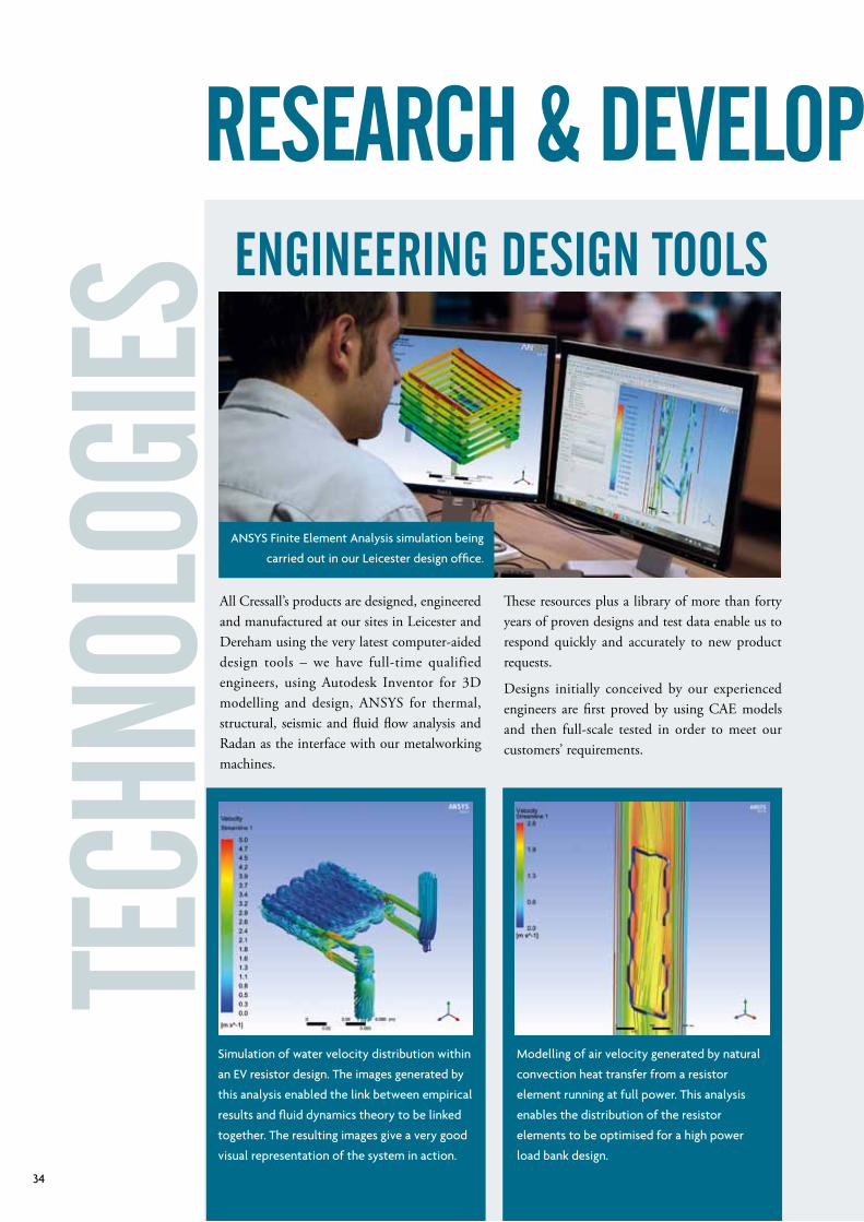
All Cressall’s products are designed, engineered and manufactured at our sites in Leicester and Dereham using the very latest computer-aided design tools – we have full-time qualified engineers, using Autodesk Inventor for 3D modelling and design, ANSYS for thermal,structural, seismic and fluid flow analysis and Radan as the interface with our metalworking machines.
ANSYS Finite Element Analysis simulation being
carried out in our Leicester design office.
eNgiNeeriNg DesigN tools
These resources plus a library of more than forty years of proven designs and test data enable us to respond quickly and accurately to new product requests.
Designs initially conceived by our experienced engineers are first proved by using CAE models and then full-scale tested in order to meet our customers’ requirements.
Modelling of air velocity generated by natural
convection heat transfer from a resistor
element running at full power. This analysis
enables the distribution of the resistor
elements to be optimised for a high power
load bank design.
research & DeveloPmeNt
35Cressall
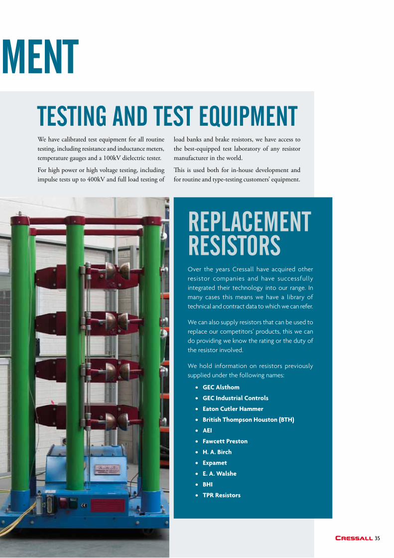
We have calibrated test equipment for all routine testing, including resistance and inductance meters, temperature gauges and a 100kV dielectric tester.
For high power or high voltage testing, including impulse tests up to 400kV and full load testing of
load banks and brake resistors, we have access to the best-equipped test laboratory of any resistor manufacturer in the world.
This is used both for in-house development and for routine and type-testing customers’ equipment.
Over the years Cressall have acquired other resistor companies and have successfully integrated their technology into our range. In many cases this means we have a library of technical and contract data to which we can refer.
We can also supply resistors that can be used to replace our competitors’ products, this we can do providing we know the rating or the duty of the resistor involved.
We hold information on resistors previously supplied under the following names:
• GEC alsthom
• GEC industrial Controls
• Eaton Cutler Hammer
• british thompson Houston (btH)
• aEi
• Fawcett Preston
• H. a. birch
• Expamet
• E. a. Walshe
• bHi
• tPR Resistors
testiNg aND test eQuiPmeNt
research & DeveloPmeNt
rePlacemeNt resistors
YouR LoCaL DiStRibutoR:
Issu
e 1 ©
201
6 C
ress
all R
esis
tors
Ltd
Cressall
HEaD oFFiCE aND FaCtoRY:Evington Valley Road, Leicester LE5 5LZTel: +44 116 273 3633Fax: +44 116 273 7911Email: [email protected]
SPECiaL PRoJECtS aND tRaNSit:11 Royson Way, Dereham, Norfolk NR19 1WDTel: +44 1362 852920Fax: +44 1362 852921
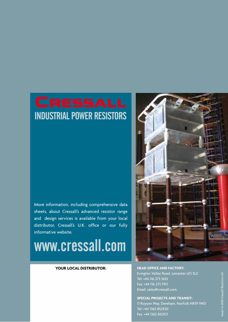
iNDustrial PoWer resistors
More information, including comprehensive data
sheets, about Cressall’s advanced resistor range
and design services is available from your local
distributor, Cressall’s U.K. office or our fully
informative website.
www.cressall.com


![REGENERATIVE BRAKING SYSTEM IN ELECTRIC VEHICLES · REGENERATIVE BRAKING SYSTEM IN ELECTRIC VEHICLES ... REGENERATIVE BRAKING SYSTEM ... Regenerative action during braking[9]](https://img.pdfslide.us/doc/110x75/5adccef67f8b9a1a088c7cf0/regenerative-braking-system-in-electric-vehicles-braking-system-in-electric-vehicles.jpg)
![Project Planning for Controlled and Non-Controlled …=Braking distance at 60% of the selected braking torque[s B_60%] = m v B =Speed of application during brake application[v B] =](https://img.pdfslide.us/doc/110x75/5fe1891a9159f66a535e7f9c/project-planning-for-controlled-and-non-controlled-braking-distance-at-60-of-the.jpg)