Embed Size (px)
Citation preview
Creo Parametric 2.0 Lesson 14
©2014CengageLearning.AllRightsReserved.Maynotbescanned,copiedorduplicated,orpostedtoapubliclyaccessiblewebsite,inwholeorinpart. 629
Lesson 14 Blends
Figure 14.1 Cap
OBJECTIVES
Create a Parallel Blend feature Use the Shell Tool Create a Hole Pattern
REFERENCES AND RESOURCES
For Resources go to www.cad-resources.com > click on the Creo Parametric 2.0 Book cover
Lesson 14 Lecture Book Projects PDF Project Lectures Creo Parametric 2.0 Quick Reference Card
http://www.cad-resources.com/Creo_Parametric_Qick_reference_cards.pdf Creo Parametric 2.0 Configuration Options
http://www.cad-resources.com/Creo_1.0_configoptions.pdf
BLENDS
A blended feature consists of a series of at least two planar sections that are joined together at their edges with transitional surfaces to form a continuous feature. The Cap in Figure 14.1 uses a simple blend feature in its design. A Blend can be created as a Parallel Blend as used here, or you can construct a Swept Blend.
Blend Sections
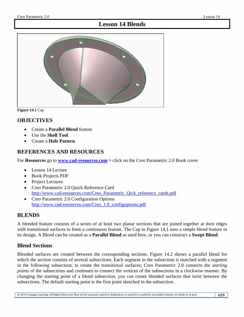
Blended surfaces are created between the corresponding sections. Figure 14.2 shows a parallel blend for which the section consists of several subsections. Each segment in the subsection is matched with a segment in the following subsection; to create the transitional surfaces; Creo Parametric 2.0 connects the starting points of the subsections and continues to connect the vertices of the subsections in a clockwise manner. By changing the starting point of a blend subsection, you can create blended surfaces that twist between the subsections. The default starting point is the first point sketched in the subsection.
Creo Parametric 2.0 Lesson 14
©2014CengageLearning.AllRightsReserved.Maynotbescanned,copiedorduplicated,orpostedtoapubliclyaccessiblewebsite,inwholeorinpart. 630
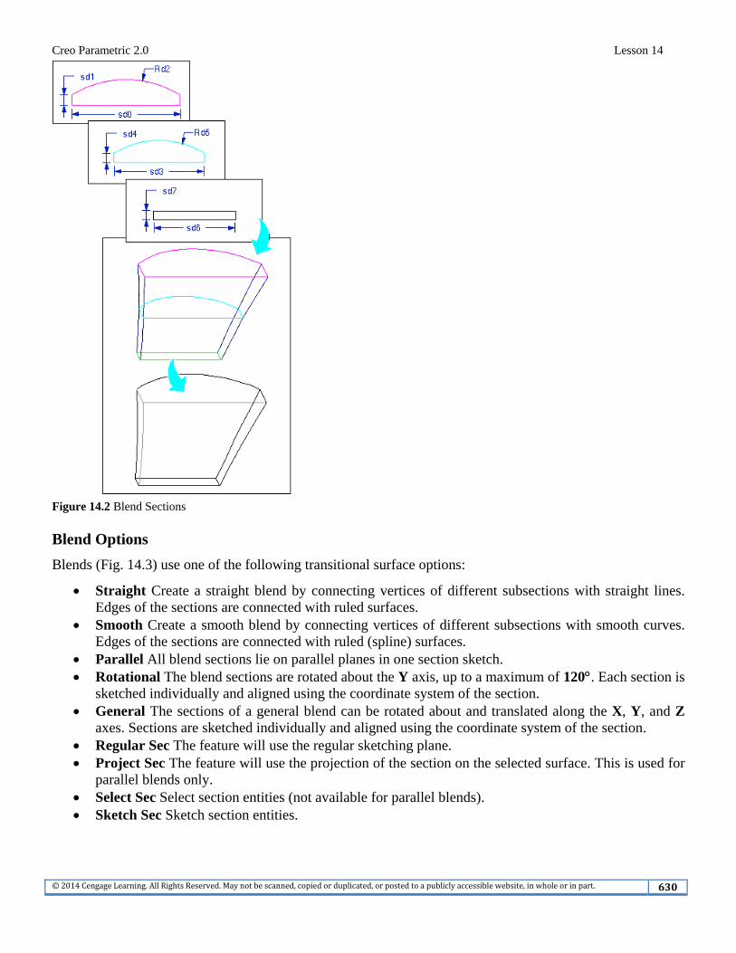
Figure 14.2 Blend Sections Blend Options Blends (Fig. 14.3) use one of the following transitional surface options:
Straight Create a straight blend by connecting vertices of different subsections with straight lines. Edges of the sections are connected with ruled surfaces.
Smooth Create a smooth blend by connecting vertices of different subsections with smooth curves. Edges of the sections are connected with ruled (spline) surfaces.
Parallel All blend sections lie on parallel planes in one section sketch. Rotational The blend sections are rotated about the Y axis, up to a maximum of 120. Each section is
sketched individually and aligned using the coordinate system of the section. General The sections of a general blend can be rotated about and translated along the X, Y, and Z
axes. Sections are sketched individually and aligned using the coordinate system of the section. Regular Sec The feature will use the regular sketching plane. Project Sec The feature will use the projection of the section on the selected surface. This is used for
parallel blends only. Select Sec Select section entities (not available for parallel blends). Sketch Sec Sketch section entities.
Creo Parametric 2.0 Lesson 14
©2014CengageLearning.AllRightsReserved.Maynotbescanned,copiedorduplicated,orpostedtoapubliclyaccessiblewebsite,inwholeorinpart. 631
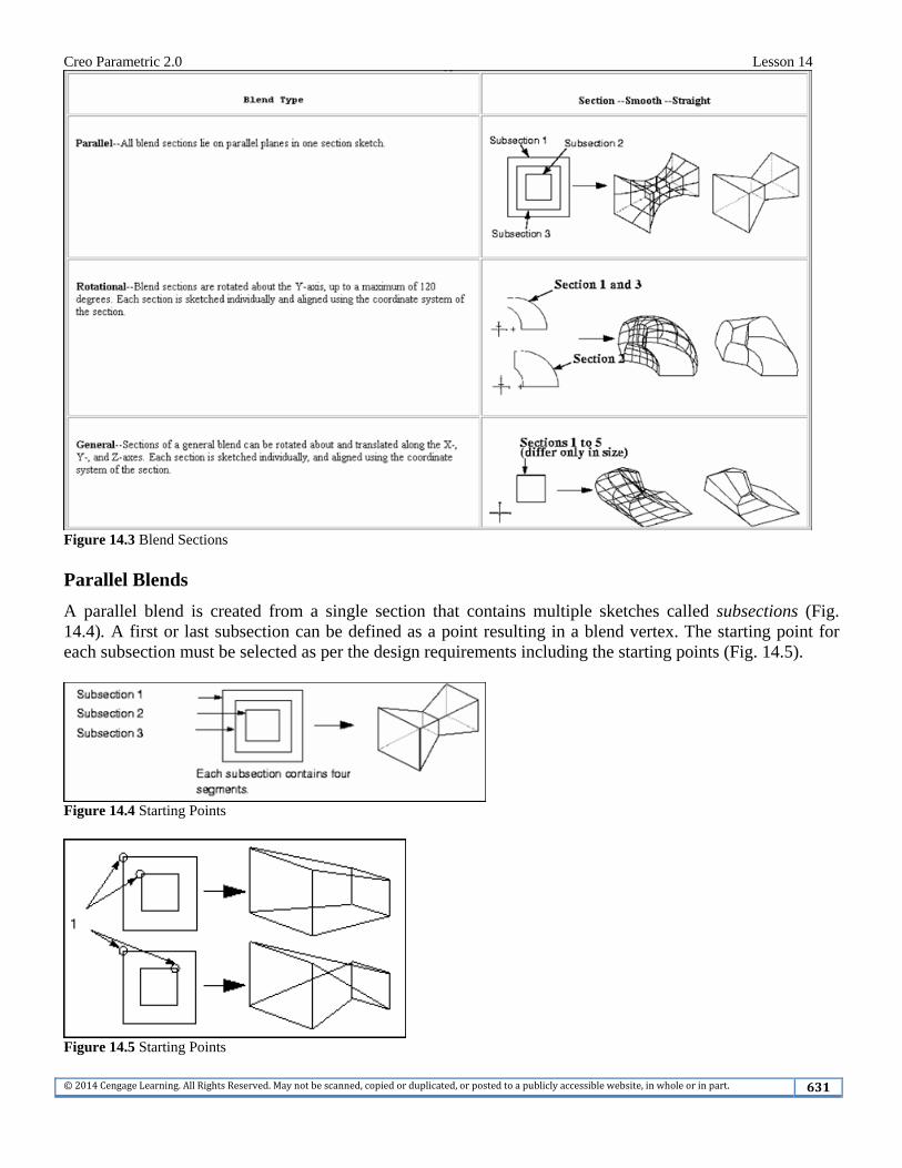
Figure 14.3 Blend Sections Parallel Blends A parallel blend is created from a single section that contains multiple sketches called subsections (Fig. 14.4). A first or last subsection can be defined as a point resulting in a blend vertex. The starting point for each subsection must be selected as per the design requirements including the starting points (Fig. 14.5).
Figure 14.4 Starting Points
Figure 14.5 Starting Points
Creo Parametric 2.0 Lesson 14
©2014CengageLearning.AllRightsReserved.Maynotbescanned,copiedorduplicated,orpostedtoapubliclyaccessiblewebsite,inwholeorinpart. 632
Lesson 14 STEPS
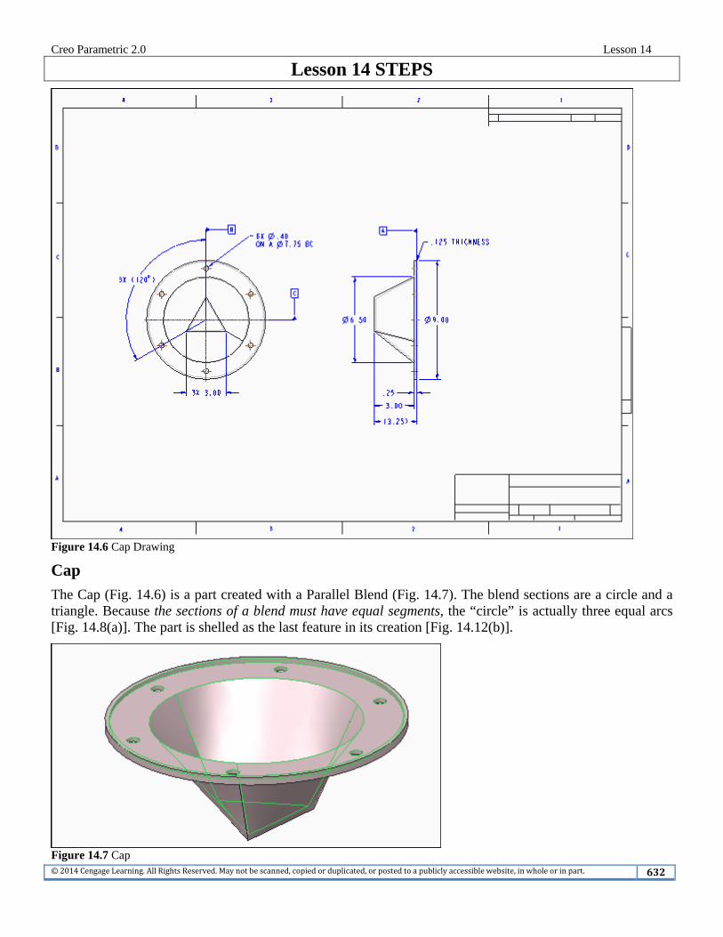
Figure 14.6 Cap Drawing
Cap
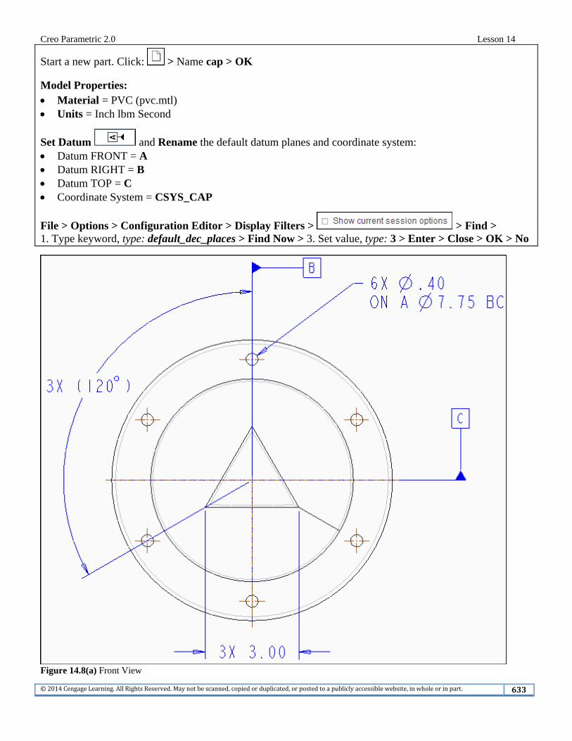
The Cap (Fig. 14.6) is a part created with a Parallel Blend (Fig. 14.7). The blend sections are a circle and a triangle. Because the sections of a blend must have equal segments, the “circle” is actually three equal arcs [Fig. 14.8(a)]. The part is shelled as the last feature in its creation [Fig. 14.12(b)].
Figure 14.7 Cap
Creo Parametric 2.0 Lesson 14
©2014CengageLearning.AllRightsReserved.Maynotbescanned,copiedorduplicated,orpostedtoapubliclyaccessiblewebsite,inwholeorinpart. 633
Start a new part. Click: > Name cap > OK
Model Properties: Material = PVC (pvc.mtl) Units = Inch lbm Second
Set Datum and Rename the default datum planes and coordinate system: Datum FRONT = A Datum RIGHT = B Datum TOP = C Coordinate System = CSYS_CAP
File > Options > Configuration Editor > Display Filters > > Find > 1. Type keyword, type: default_dec_places > Find Now > 3. Set value, type: 3 > Enter > Close > OK > No
Figure 14.8(a) Front View
Creo Parametric 2.0 Lesson 14
©2014CengageLearning.AllRightsReserved.Maynotbescanned,copiedorduplicated,orpostedtoapubliclyaccessiblewebsite,inwholeorinpart. 634
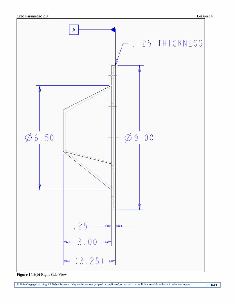
Figure 14.8(b) Right Side View
Creo Parametric 2.0 Lesson 14
©2014CengageLearning.AllRightsReserved.Maynotbescanned,copiedorduplicated,orpostedtoapubliclyaccessiblewebsite,inwholeorinpart. 635
For Lessons 13-18, step-by-step commands are limited to new software commands introduced or enhanced in that lesson. You will be expected to do most of the modeling using commands and practices mastered from Lessons 1-12 without repeated detailed explanations. Refer to Figures 14.8(a-b) for the Cap dimensions. Model the circular protrusion that is 9.00 by .25 thick (Fig. 14.9). Sketch the first extrusion on datum A (FRONT) and centered on B (RIGHT) and C (TOP). After having SET Datum Tag annotations and renaming the default datum planes: pick datum B from the Model Tree > RMB > Properties > Text Style > Height 0.15625 > Enter > Apply > OK > OK > repeat for datum C and datum A > LMB to deselect
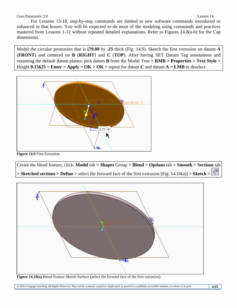
Figure 14.9 First Extrusion Create the blend feature, click: Model tab > Shapes Group > Blend > Options tab > Smooth > Sections tab
> Sketched sections > Define > select the forward face of the first extrusion [Fig. 14.10(a)] > Sketch >
Figure 14.10(a) Blend Feature Sketch Surface (select the forward face of the first extrusion)
Creo Parametric 2.0 Lesson 14
©2014CengageLearning.AllRightsReserved.Maynotbescanned,copiedorduplicated,orpostedtoapubliclyaccessiblewebsite,inwholeorinpart. 636
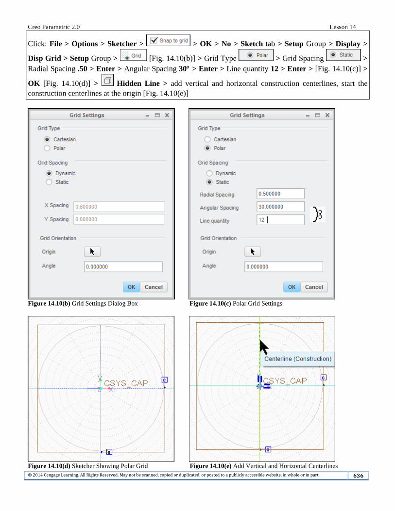
Click: File > Options > Sketcher > > OK > No > Sketch tab > Setup Group > Display >
Disp Grid > Setup Group > [Fig. 14.10(b)] > Grid Type > Grid Spacing > Radial Spacing .50 > Enter > Angular Spacing 30 > Enter > Line quantity 12 > Enter > [Fig. 14.10(c)] >
OK [Fig. 14.10(d)] > Hidden Line > add vertical and horizontal construction centerlines, start the construction centerlines at the origin [Fig. 14.10(e)]
Figure 14.10(b) Grid Settings Dialog Box Figure 14.10(c) Polar Grid Settings
Figure 14.10(d) Sketcher Showing Polar Grid Figure 14.10(e) Add Vertical and Horizontal Centerlines
Creo Parametric 2.0 Lesson 14
©2014CengageLearning.AllRightsReserved.Maynotbescanned,copiedorduplicated,orpostedtoapubliclyaccessiblewebsite,inwholeorinpart. 637
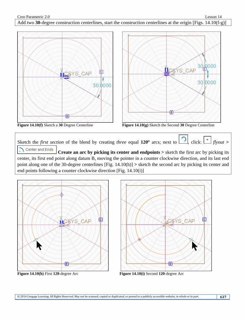
Add two 30-degree construction centerlines, start the construction centerlines at the origin [Figs. 14.10(f-g)]
Figure 14.10(f) Sketch a 30 Degree Centerline Figure 14.10(g) Sketch the Second 30 Degree Centerline
Sketch the first section of the blend by creating three equal 120 arcs; next to , click: flyout >
Create an arc by picking its center and endpoints > sketch the first arc by picking its center, its first end point along datum B, moving the pointer in a counter clockwise direction, and its last end point along one of the 30-degree centerlines [Fig. 14.10(h)] > sketch the second arc by picking its center and end points following a counter clockwise direction [Fig. 14.10(i)]
Figure 14.10(h) First 120-degree Arc Figure 14.10(i) Second 120-degree Arc
Creo Parametric 2.0 Lesson 14
©2014CengageLearning.AllRightsReserved.Maynotbescanned,copiedorduplicated,orpostedtoapubliclyaccessiblewebsite,inwholeorinpart. 638
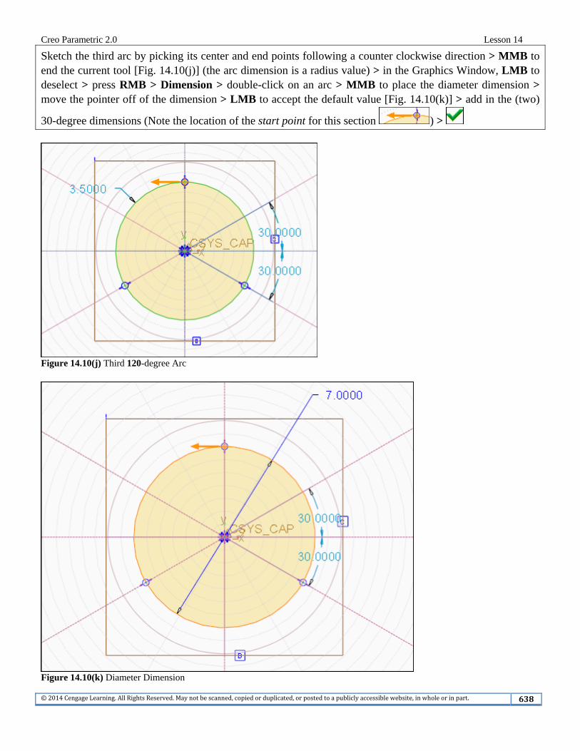
Sketch the third arc by picking its center and end points following a counter clockwise direction > MMB to end the current tool [Fig. 14.10(j)] (the arc dimension is a radius value) > in the Graphics Window, LMB to deselect > press RMB > Dimension > double-click on an arc > MMB to place the diameter dimension > move the pointer off of the dimension > LMB to accept the default value [Fig. 14.10(k)] > add in the (two)
30-degree dimensions (Note the location of the start point for this section ) >
Figure 14.10(j) Third 120-degree Arc
Figure 14.10(k) Diameter Dimension
Creo Parametric 2.0 Lesson 14
©2014CengageLearning.AllRightsReserved.Maynotbescanned,copiedorduplicated,orpostedtoapubliclyaccessiblewebsite,inwholeorinpart. 639
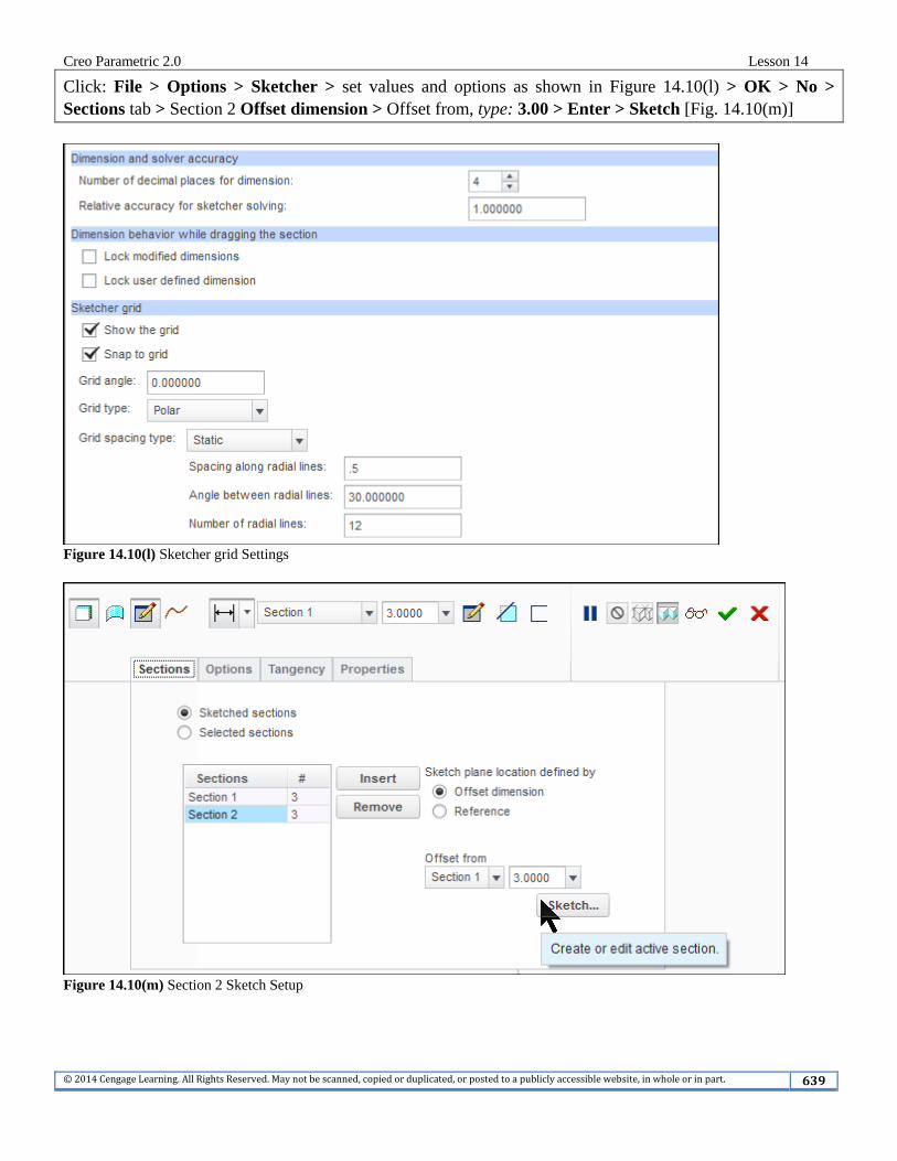
Click: File > Options > Sketcher > set values and options as shown in Figure 14.10(l) > OK > No > Sections tab > Section 2 Offset dimension > Offset from, type: 3.00 > Enter > Sketch [Fig. 14.10(m)]
Figure 14.10(l) Sketcher grid Settings
Figure 14.10(m) Section 2 Sketch Setup
Creo Parametric 2.0 Lesson 14
©2014CengageLearning.AllRightsReserved.Maynotbescanned,copiedorduplicated,orpostedtoapubliclyaccessiblewebsite,inwholeorinpart. 640
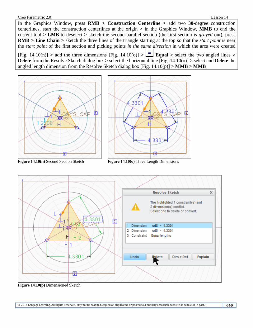
In the Graphics Window, press RMB > Construction Centerline > add two 30-degree construction centerlines, start the construction centerlines at the origin > in the Graphics Window, MMB to end the current tool > LMB to deselect > sketch the second parallel section (the first section is grayed out), press RMB > Line Chain > sketch the three lines of the triangle starting at the top so that the start point is near the start point of the first section and picking points in the same direction in which the arcs were created
[Fig. 14.10(n)] > add the three dimensions [Fig. 14.10(o)] > Equal > select the two angled lines > Delete from the Resolve Sketch dialog box > select the horizontal line [Fig. 14.10(o)] > select and Delete the angled length dimension from the Resolve Sketch dialog box [Fig. 14.10(p)] > MMB > MMB
Figure 14.10(n) Second Section Sketch Figure 14.10(o) Three Length Dimensions
Figure 14.10(p) Dimensioned Sketch
Creo Parametric 2.0 Lesson 14
©2014CengageLearning.AllRightsReserved.Maynotbescanned,copiedorduplicated,orpostedtoapubliclyaccessiblewebsite,inwholeorinpart. 641
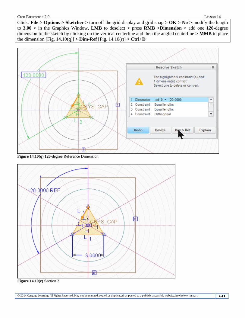
Click: File > Options > Sketcher > turn off the grid display and grid snap > OK > No > modify the length to 3.00 > in the Graphics Window, LMB to deselect > press RMB >Dimension > add one 120-degree dimension to the sketch by clicking on the vertical centerline and then the angled centerline > MMB to place the dimension [Fig. 14.10(q)] > Dim-Ref [Fig. 14.10(r)] > Ctrl+D
Figure 14.10(q) 120-degree Reference Dimension
Figure 14.10(r) Section 2
Creo Parametric 2.0 Lesson 14
©2014CengageLearning.AllRightsReserved.Maynotbescanned,copiedorduplicated,orpostedtoapubliclyaccessiblewebsite,inwholeorinpart. 642
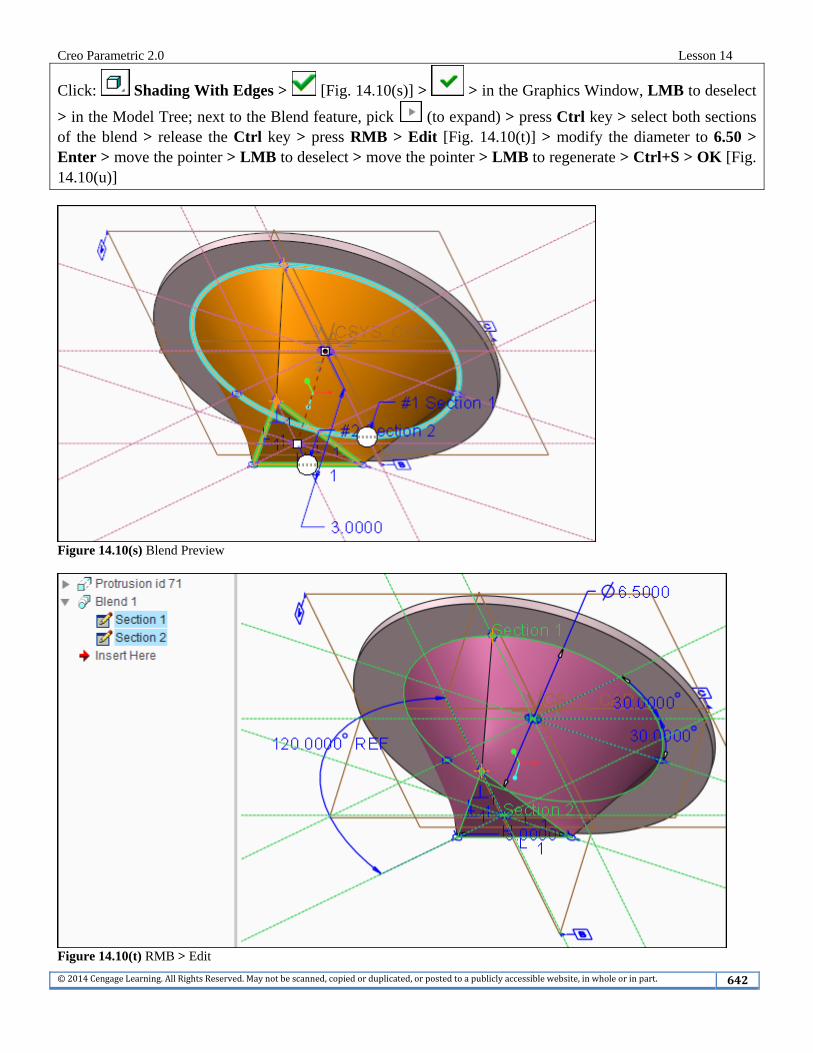
Click: Shading With Edges > [Fig. 14.10(s)] > > in the Graphics Window, LMB to deselect
> in the Model Tree; next to the Blend feature, pick (to expand) > press Ctrl key > select both sections of the blend > release the Ctrl key > press RMB > Edit [Fig. 14.10(t)] > modify the diameter to 6.50 > Enter > move the pointer > LMB to deselect > move the pointer > LMB to regenerate > Ctrl+S > OK [Fig. 14.10(u)]
Figure 14.10(s) Blend Preview
Figure 14.10(t) RMB > Edit
Creo Parametric 2.0 Lesson 14
©2014CengageLearning.AllRightsReserved.Maynotbescanned,copiedorduplicated,orpostedtoapubliclyaccessiblewebsite,inwholeorinpart. 643
Figure 14.10(u) Completed Blend
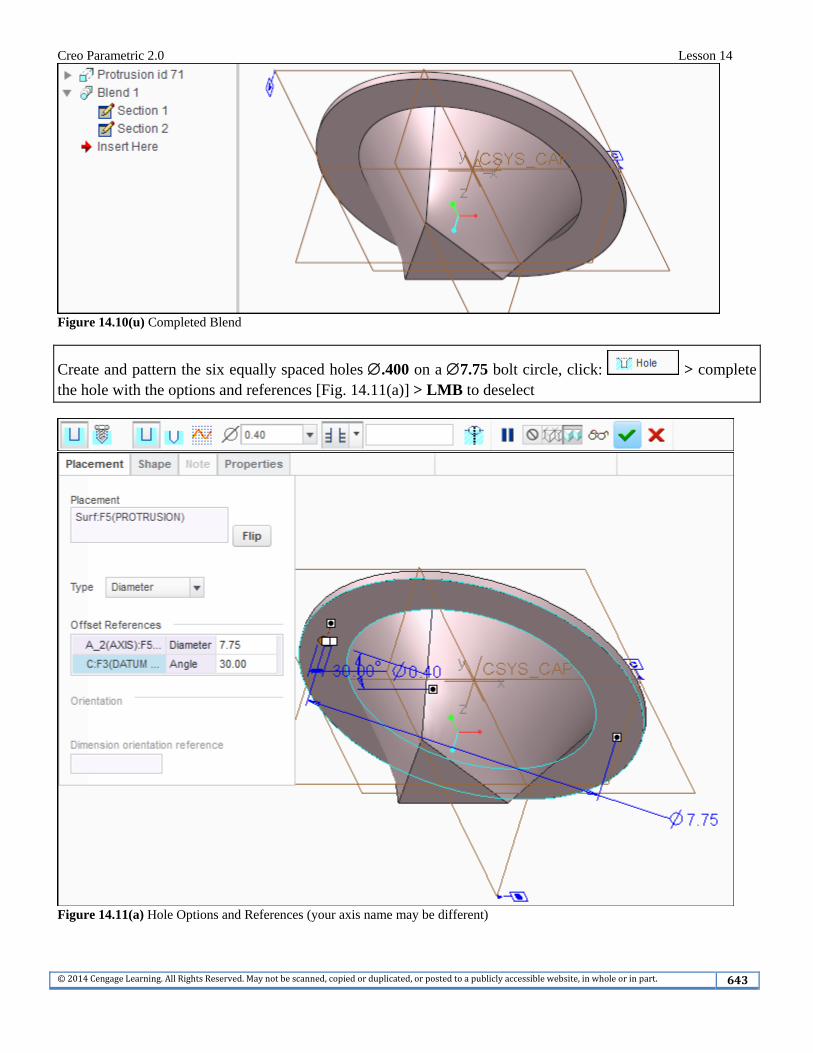
Create and pattern the six equally spaced holes .400 on a 7.75 bolt circle, click: > complete the hole with the options and references [Fig. 14.11(a)] > LMB to deselect
Figure 14.11(a) Hole Options and References (your axis name may be different)
Creo Parametric 2.0 Lesson 14
©2014CengageLearning.AllRightsReserved.Maynotbescanned,copiedorduplicated,orpostedtoapubliclyaccessiblewebsite,inwholeorinpart. 644
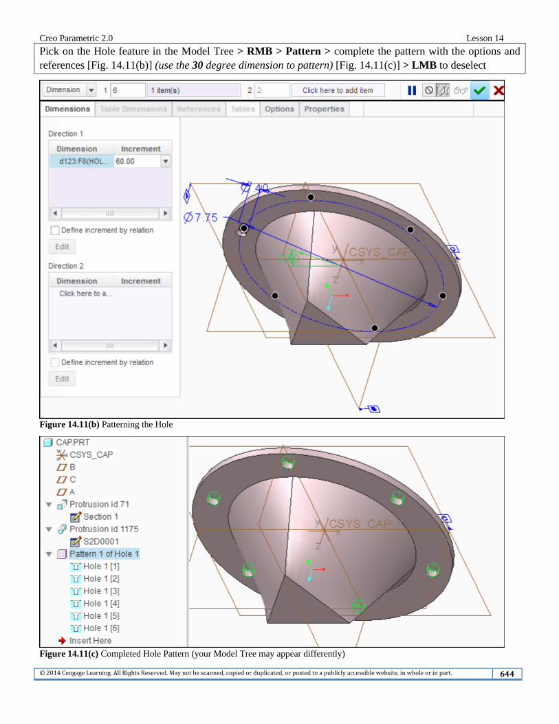
Pick on the Hole feature in the Model Tree > RMB > Pattern > complete the pattern with the options and references [Fig. 14.11(b)] (use the 30 degree dimension to pattern) [Fig. 14.11(c)] > LMB to deselect
Figure 14.11(b) Patterning the Hole
Figure 14.11(c) Completed Hole Pattern (your Model Tree may appear differently)
Creo Parametric 2.0 Lesson 14
©2014CengageLearning.AllRightsReserved.Maynotbescanned,copiedorduplicated,orpostedtoapubliclyaccessiblewebsite,inwholeorinpart. 645
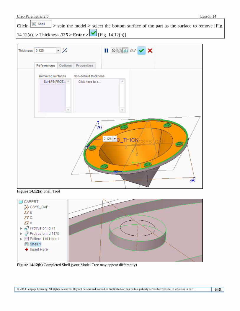
Click: > spin the model > select the bottom surface of the part as the surface to remove [Fig.
14.12(a)] > Thickness .125 > Enter > [Fig. 14.12(b)]
Figure 14.12(a) Shell Tool
Figure 14.12(b) Completed Shell (your Model Tree may appear differently)
Creo Parametric 2.0 Lesson 14
©2014CengageLearning.AllRightsReserved.Maynotbescanned,copiedorduplicated,orpostedtoapubliclyaccessiblewebsite,inwholeorinpart. 646
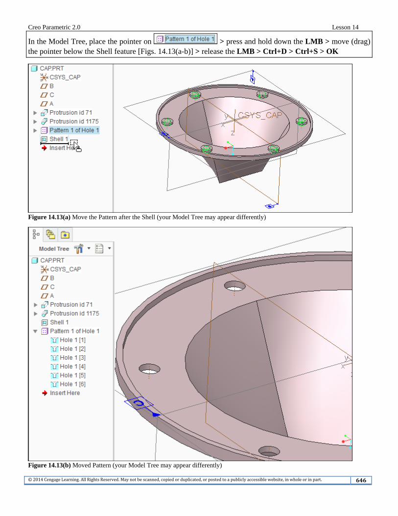
In the Model Tree, place the pointer on > press and hold down the LMB > move (drag) the pointer below the Shell feature [Figs. 14.13(a-b)] > release the LMB > Ctrl+D > Ctrl+S > OK
Figure 14.13(a) Move the Pattern after the Shell (your Model Tree may appear differently)
Figure 14.13(b) Moved Pattern (your Model Tree may appear differently)
Creo Parametric 2.0 Lesson 14
©2014CengageLearning.AllRightsReserved.Maynotbescanned,copiedorduplicated,orpostedtoapubliclyaccessiblewebsite,inwholeorinpart. 647
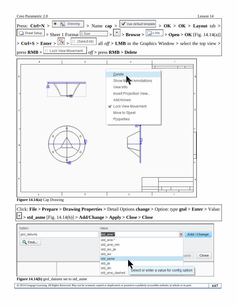
Press: Ctrl+N > > Name cap > > OK > OK > Layout tab >
> Sheet 1 Format > > Browse > > Open > OK [Fig. 14.14(a)]
> Ctrl+S > Enter > > all off > LMB in the Graphics Window > select the top view >
press RMB > off > press RMB > Delete
Figure 14.14(a) Cap Drawing
Click: File > Prepare > Drawing Properties > Detail Options change > Option: type gtol > Enter > Value:
> std_asme [Fig. 14.14(b)] > Add/Change > Apply > Close > Close
Figure 14.14(b) gtol_datums set to std_asme
Creo Parametric 2.0 Lesson 14
©2014CengageLearning.AllRightsReserved.Maynotbescanned,copiedorduplicated,orpostedtoapubliclyaccessiblewebsite,inwholeorinpart. 648
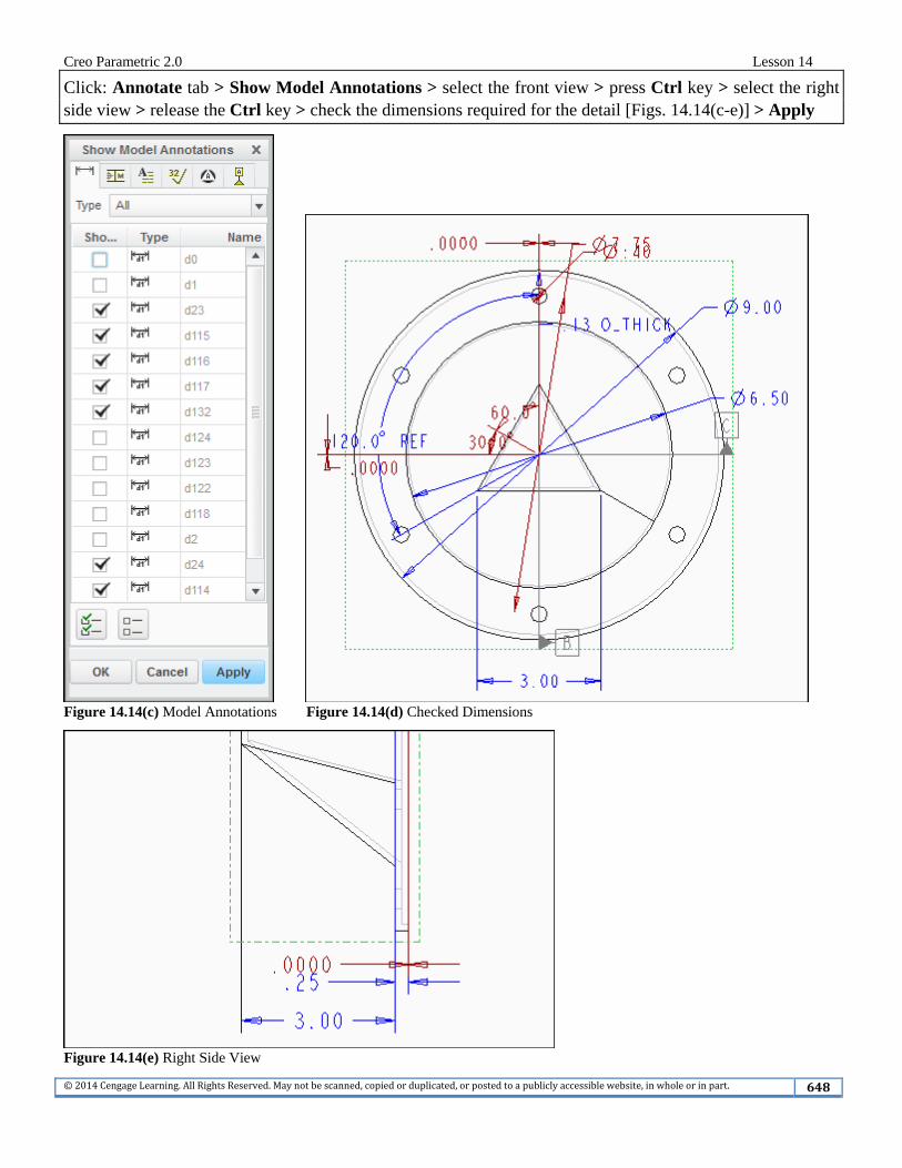
Click: Annotate tab > Show Model Annotations > select the front view > press Ctrl key > select the right side view > release the Ctrl key > check the dimensions required for the detail [Figs. 14.14(c-e)] > Apply
Figure 14.14(c) Model Annotations Figure 14.14(d) Checked Dimensions
Figure 14.14(e) Right Side View
Creo Parametric 2.0 Lesson 14
©2014CengageLearning.AllRightsReserved.Maynotbescanned,copiedorduplicated,orpostedtoapubliclyaccessiblewebsite,inwholeorinpart. 649
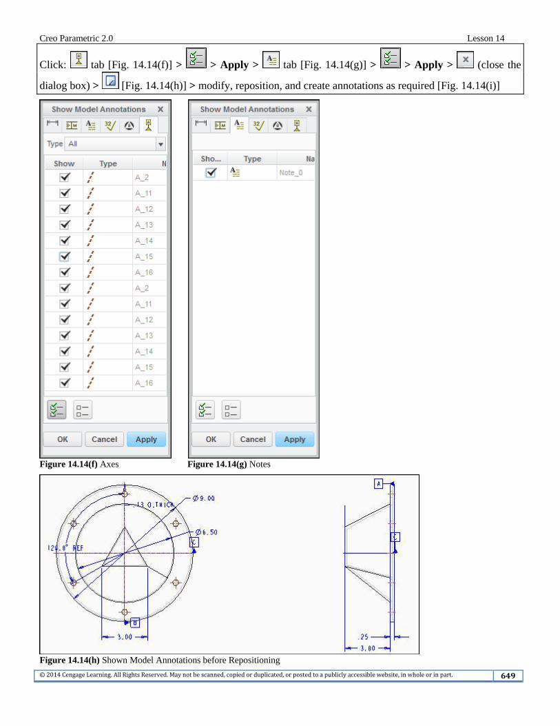
Click: tab [Fig. 14.14(f)] > > Apply > tab [Fig. 14.14(g)] > > Apply > (close the
dialog box) > [Fig. 14.14(h)] > modify, reposition, and create annotations as required [Fig. 14.14(i)]
Figure 14.14(f) Axes Figure 14.14(g) Notes
Figure 14.14(h) Shown Model Annotations before Repositioning
Creo Parametric 2.0 Lesson 14
©2014CengageLearning.AllRightsReserved.Maynotbescanned,copiedorduplicated,orpostedtoapubliclyaccessiblewebsite,inwholeorinpart. 650
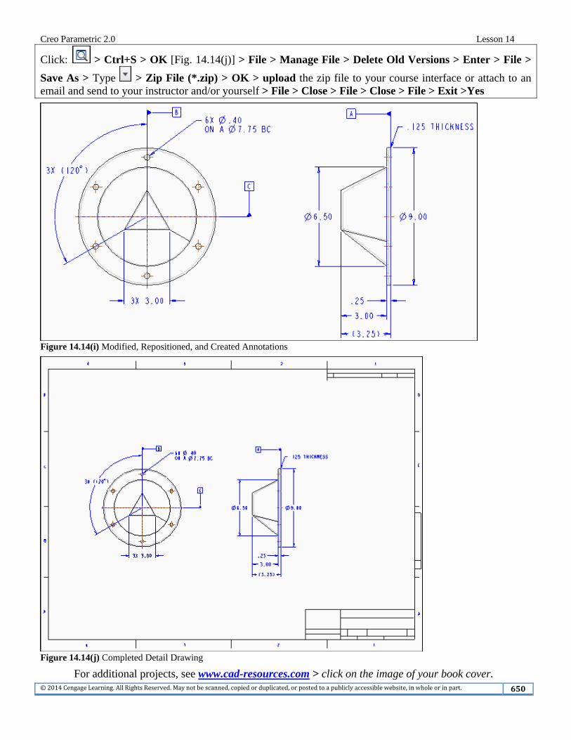
Click: > Ctrl+S > OK [Fig. 14.14(j)] > File > Manage File > Delete Old Versions > Enter > File >
Save As > Type > Zip File (*.zip) > OK > upload the zip file to your course interface or attach to an email and send to your instructor and/or yourself > File > Close > File > Close > File > Exit >Yes
Figure 14.14(i) Modified, Repositioned, and Created Annotations
Figure 14.14(j) Completed Detail Drawing
For additional projects, see www.cad-resources.com > click on the image of your book cover.


![#4378-Gov N226-Act 8 of 2009 - laws.parliament.na€¦ · Web view[The plural word “subsections” should be the singular word “subsection”.] (3)A person who contravenes subsection](https://img.pdfslide.us/doc/110x75/5e189befe463ce38db30eac0/4378-gov-n226-act-8-of-2009-laws-web-viewthe-plural-word-aoesubsectionsa.jpg)