Embed Size (px)
Citation preview
Crematoria
guidelines on best available techniques and provisional guidance
on best environmental practices
relevant to article 5 and annex c of the stockholm convention on
persistent organic pollutants
This publication may be reproduced in whole or in part in any form for educational or non-profit purposes without special permission, provided acknowledgement of the source is made. The Secretariat of the Stockholm Convention and UNEP would appreciate receiving a copy of any publication that uses this publication as a source. No use of this publication may be made for resale or for any other commercial purpose whatsoever without prior permission in writing from the United Nations Environment Programme.
Published by the Secretariat of the Stockholm Convention on Persistent Organic Pollutants in October 2008. For more information please contact:
Secretariat of the Stockholm Convention on Persistent Organic Pollutants United Nations Environment ProgrammeInternational Environment House11-13 chemin des AnémonesCH-1219, Châtelaine, Geneva, Switzerland [email protected] - www.pops.int
Designed and printed by: SRO-Kundig - Geneva
MAY 2007, GENEVA, SWITZERLAND
GUIDELINES ON BEST AVAILABLETECHNIQUES AND PROVISIONAL GUIDANCE
ON BEST ENVIRONMENTAL PRACTICES
relevant to Article 5 and Annex Cof the Stockholm Convention on
Persistent Organic Pollutants
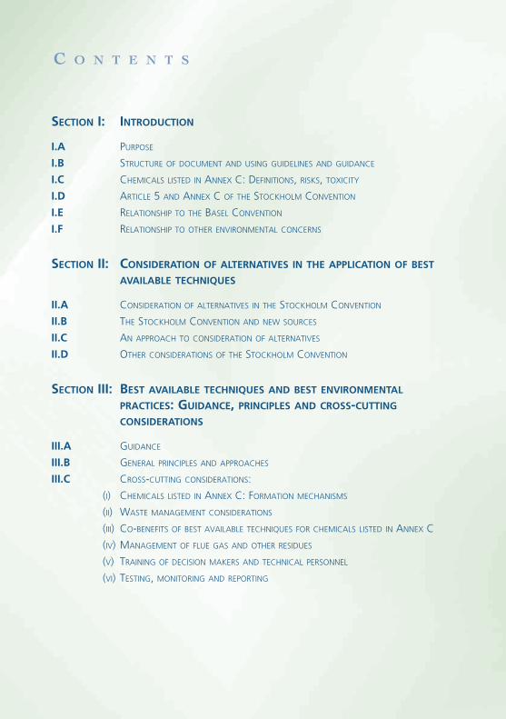
SECTION I: INTRODUCTION
I.A PURPOSE
I.B STRUCTURE OF DOCUMENT AND USING GUIDELINES AND GUIDANCE
I.C CHEMICALS LISTED IN ANNEX C: DEFINITIONS, RISKS, TOXICITY
I.D ARTICLE 5 AND ANNEX C OF THE STOCKHOLM CONVENTION
I.E RELATIONSHIP TO THE BASEL CONVENTION
I.F RELATIONSHIP TO OTHER ENVIRONMENTAL CONCERNS
SECTION II: CONSIDERATION OF ALTERNATIVES IN THE APPLICATION OF BEST
AVAILABLE TECHNIQUES
II.A CONSIDERATION OF ALTERNATIVES IN THE STOCKHOLM CONVENTION
II.B THE STOCKHOLM CONVENTION AND NEW SOURCES
II.C AN APPROACH TO CONSIDERATION OF ALTERNATIVES
II.D OTHER CONSIDERATIONS OF THE STOCKHOLM CONVENTION
SECTION III: BEST AVAILABLE TECHNIQUES AND BEST ENVIRONMENTAL
PRACTICES: GUIDANCE, PRINCIPLES AND CROSS-CUTTINGCONSIDERATIONS
III.A GUIDANCE
III.B GENERAL PRINCIPLES AND APPROACHES
III.C CROSS-CUTTING CONSIDERATIONS:
(I) CHEMICALS LISTED IN ANNEX C: FORMATION MECHANISMS
(II) WASTE MANAGEMENT CONSIDERATIONS
(III) CO-BENEFITS OF BEST AVAILABLE TECHNIQUES FOR CHEMICALS LISTED IN ANNEX C
(IV) MANAGEMENT OF FLUE GAS AND OTHER RESIDUES
(V) TRAINING OF DECISION MAKERS AND TECHNICAL PERSONNEL
(VI) TESTING, MONITORING AND REPORTING
C o n t e n t s
SECTION IV: COMPILATION OF SUMMARIES FROM THE SOURCE CATEGORIES
INCLUDED IN SECTIONS V AND VI
SUMMARIES OF SECTION V: SOURCE CATEGORIES INCLUDED IN PART II OF ANNEX C
SUMMARIES OF SECTION VI: SOURCE CATEGORIES INCLUDED IN PART III OF ANNEX C
SECTION V: GUIDANCE/GUIDELINES BY SOURCE CATEGORIES: SOURCECATEGORIES IN PART II OF ANNEX C
V.A WASTE INCINERATORS
(I) MUNICIPAL SOLID WASTE, HAZARDOUS WASTE AND SEWAGE SLUDGE
(II) MEDICAL WASTE
V.B CEMENT KILNS FIRING HAZARDOUS WASTE
V.C PRODUCTION OF PULP USING ELEMENTAL CHLORINE OR CHEMICALS GENERATING
ELEMENTAL CHLORINE
V.D THERMAL PROCESSES IN THE METALLURGICAL INDUSTRY
(I) SECONDARY COPPER PRODUCTION
(II) SINTER PLANTS IN THE IRON AND STEEL INDUSTRY
(III) SECONDARY ALUMINIUM PRODUCTION
(IV) SECONDARY ZINC PRODUCTION
SECTION VI: GUIDANCE/GUIDELINES BY SOURCE CATEGORIES: SOURCECATEGORIES IN PART III OF ANNEX C
VI.A OPEN BURNING OF WASTE, INCLUDING BURNING OF LANDFILL SITES
VI.B THERMAL PROCESSES IN THE METALLURGICAL INDUSTRY NOT MENTIONED IN ANNEX CPART II
(I) SECONDARY LEAD PRODUCTION
(II) PRIMARY ALUMINIUM PRODUCTION
(III) MAGNESIUM PRODUCTION
(IV) SECONDARY STEEL PRODUCTION
(V) PRIMARY BASE METALS SMELTING
VI.C RESIDENTIAL COMBUSTION SOURCES
VI.D FOSSIL FUEL-FIRED UTILITY AND INDUSTRIAL BOILERS
VI.E FIRING INSTALLATIONS FOR WOOD AND OTHER BIOMASS FUELS
VI.F SPECIFIC CHEMICAL PRODUCTION PROCESSES RELEASING CHEMICALS LISTED IN ANNEX C
VI.G CREMATORIA
VI.H MOTOR VEHICLES, PARTICULARLY THOSE BURNING LEADED GASOLINE
VI.I DESTRUCTION OF ANIMAL CARCASSES
VI.J TEXTILE AND LEATHER DYEING (WITH CHLORANIL) AND FINISHING
(WITH ALKALINE EXTRACTION)
VI.K SHREDDER PLANTS FOR THE TREATMENT OF END-OF-LIFE VEHICLES
VI.L SMOULDERING OF COPPER CABLES
VI.M WASTE OIL REFINERIES

Secti
on
VI.G
Guidan
ce/guidelines by source category:
Source categories in Part III of Annex C

Part III So
urce category (g):
Crematoria
VI.G Crematoria .....................................................................................................9
1. Process description ...........................................................................................9
2. Sources of chemicals listed in Annex C of the Stockholm Convention ............11
2.1 General information on emissions from crematoria .............................11
2.2 Emissions of PCDD/PCDF to air ...........................................................11
2.3 Releases to other media ......................................................................12
3. Recommended processes................................................................................12
3.1 Overview.............................................................................................12
3.2 Best available techniques ....................................................................12
3.3 Best environmental practices...............................................................13
4. Primary and secondary measures ....................................................................14
4.1 Primary measures ................................................................................14
4.2 Secondary measures............................................................................15
5. Summary of measures ....................................................................................16
6. Performance levels associated with best available techniques and bestenvironmental practices..................................................................................19
References .................................................................................................................19
Tables
Table 1. Measures for recommended processes for crematoria.................................16
Table 2. Summary of primary and secondary measures for crematoria .....................17
Illustrations
Figure 1. Schematic of a typical cremation process ....................................................10
C o n t e n t s
Section VI.G - Part III Source category (g):Crematoria 7

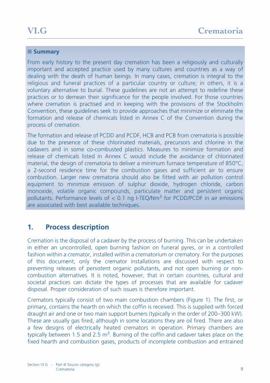
VI.G Crematoria
� Summary
From early history to the present day cremation has been a religiously and culturallyimportant and accepted practice used by many cultures and countries as a way ofdealing with the death of human beings. In many cases, cremation is integral to thereligious and funeral practices of a particular country or culture; in others, it is avoluntary alternative to burial. These guidelines are not an attempt to redefine thesepractices or to demean their significance for the people involved. For those countrieswhere cremation is practised and in keeping with the provisions of the StockholmConvention, these guidelines seek to provide approaches that minimize or eliminate theformation and release of chemicals listed in Annex C of the Convention during theprocess of cremation.
The formation and release of PCDD and PCDF, HCB and PCB from crematoria is possibledue to the presence of these chlorinated materials, precursors and chlorine in thecadavers and in some co-combusted plastics. Measures to minimize formation andrelease of chemicals listed in Annex C would include the avoidance of chlorinatedmaterial, the design of crematoria to deliver a minimum furnace temperature of 850°C,a 2-second residence time for the combustion gases and sufficient air to ensurecombustion. Larger new crematoria should also be fitted with air pollution controlequipment to minimize emission of sulphur dioxide, hydrogen chloride, carbonmonoxide, volatile organic compounds, particulate matter and persistent organicpollutants. Performance levels of < 0.1 ng I-TEQ/Nm3 for PCDD/PCDF in air emissionsare associated with best available techniques.
1. Process description
Cremation is the disposal of a cadaver by the process of burning. This can be undertakenin either an uncontrolled, open burning fashion on funeral pyres, or in a controlledfashion within a cremator, installed within a crematorium or crematory. For the purposesof this document, only the cremator installations are discussed with respect topreventing releases of persistent organic pollutants, and not open burning or non-combustion alternatives. It is noted, however, that in certain countries, cultural andsocietal practices can dictate the types of processes that are available for cadaverdisposal. Proper consideration of such issues is therefore important.
Cremators typically consist of two main combustion chambers (Figure 1). The first, orprimary, contains the hearth on which the coffin is received. This is supplied with forceddraught air and one or two main support burners (typically in the order of 200–300 kW).These are usually gas fired, although in some locations they are oil fired. There are alsoa few designs of electrically heated cremators in operation. Primary chambers aretypically between 1.5 and 2.5 m3. Burning of the coffin and cadaver takes place on thefixed hearth and combustion gases, products of incomplete combustion and entrained
Section VI.G - Part III Source category (g):Crematoria 9
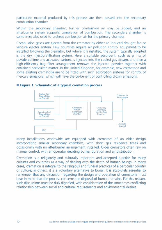
particulate material produced by this process are then passed into the secondarycombustion chamber.
Within the secondary chamber, further combustion air may be added, and anafterburner system supports completion of combustion. The secondary chamber issometimes also used to preheat combustion air for the primary chamber.
Combustion gases are ejected from the cremator by either an induced draught fan orventure ejector system. Few countries require air pollution control equipment to beinstalled following the cremator, but where it is installed, the system typically adoptedis the dry injection/filtration system. Here a suitable adsorbent, such as a mix ofpowdered lime and activated carbon, is injected into the cooled gas stream, and then ahigh-efficiency bag filter arrangement removes the injected powder together withentrained particulate matter. In the United Kingdom, for example, new crematoria andsome existing crematoria are to be fitted with such adsorption systems for control ofmercury emissions, which will have the co-benefit of controlling dioxin emissions.
� Figure 1. Schematic of a typical cremation process
Many installations worldwide are equipped with cremators of an older designincorporating smaller secondary chambers, with short gas residence times andoccasionally with no afterburner arrangement installed. Older cremators often rely onmanual control, with an operator deciding burner duration and air distribution.
Cremation is a religiously and culturally important and accepted practice for manycultures and countries as a way of dealing with the death of human beings. In manycases, cremation is integral to the religious and funeral practices of a particular countryor culture; in others, it is a voluntary alternative to burial. It is absolutely essential toremember that any discussion regarding the design and operation of crematoria mustbear in mind that the process concerns the disposal of human remains. For this reason,such discussions must be duly dignified, with consideration of the sometimes conflictingrelationship between social and cultural requirements and environmental desires.
Ashes todisposal
Emissions toAtmosphere
CrematorySecondary
CombustionChamber
CrematoryPrimary
IncinerationChamber
Body
Operating fuel(Natural Gasor Fuel oil)
Startup fuel(Natural Gasor Fuel oil)
10 Guidelines on best available techniques and provisional guidance on best environmental practices
2. Sources of chemicals listed in Annex C of the StockholmConvention
The formation and emission of polychlorinated dibenzo-p-dioxins (PCDD),polychlorinated dibenzofurans (PCDF), polychlorinated biphenyls (PCB) andhexachlorobenzene (HCB) from cremators is possible due to the presence of thesematerials, precursors and chlorine in the cadavers and in some co-combusted plastics(e.g. coffin furnishings, which have been phased out in some countries). However,although measurements of PCDD/PCDF have been undertaken from crematoria, thereare few or no consistent data for PCB and HCB emissions. Consequently levels of PCBand HCB emissions are much more uncertain than PCDD/PCDF emissions from suchsources.
2.1 General information on emissions from crematoria
Airborne emissions consist of nitrogen oxides (NOx), carbon monoxide (CO), sulphurdioxide (SO2), particulate matter, metal compounds, including mercury, organiccompounds and PCDD/PCDF.
As discussed above, some cremator plant may have air pollution control equipmentinstalled, for example lime and activated carbon injection and fabric filtration. However,most have pollution control ranging from minimal (i.e., a combustion chamber andstack) to reasonably improved systems with secondary combustion chambers andafterburners.
2.2 Emissions of PCDD/PCDF to air
PCDD/PCDF are formed through incomplete combustion or by de novo synthesis whenorganic and chlorine compounds are present in the feed material or flue gas matrix.
Although it is considered that PCDD/PCDF, PCB and HCB will be destroyed at hightemperature (minimum 850°C) in the presence of oxygen, the de novo process ofPCDD/PCDF synthesis is still possible if the combustion gases are cooled over anextended period through the reformation temperature window (between 200°C and400°C). This window can be present in abatement systems, energy recovery equipmentand in cooler parts of the furnace, for example the feed area. Care taken in the designof cooling systems to minimize the residence time in the reformation window ispractised to prevent de novo synthesis.
In many countries, cremator equipment is often installed in old buildings that are notpurpose built. Thus there are often long runs of horizontal ductwork, operating attemperatures within this reformation window. Such systems are also subject todeposition of particulate matter, often containing adsorbed precursors, which enhancethe reformation reactions.
In the United Kingdom, for example, cremators are generally required to achievePCDD/PCDF emission concentrations of less than 0.1 ng I-TEQ/m3 standardized at 11%oxygen, dry and standard temperature and pressure (0°C, 101.3 kPa).1 However, this isnot required to be demonstrated other than by achieving technical combustion
Section VI.G - Part III Source category (g):Crematoria 11
requirements of minimum residence time, temperature and oxygen in the secondarychamber.
An emissions survey of typical cremators was undertaken during discussion of revisedregulatory guidance. These tests indicated PCDD/PCDF concentrations ranging between0.01 and 0.12 ng I-TEQ/m3, and PCB concentrations were low, although limits ofdetection played a significant role in the estimation of releases.
2.3 Releases to other media
Due to the nature of the process, ashes are an ethical product and are often not subjectto any control; spreading of ashes on water, for example, is a potential release route.However, there are often depositions left within the cremator chambers and fluewaysthat are removed during routine maintenance. In the United Kingdom such material isburied at depth within the crematorium grounds (in the same way as metals recoveredfrom the hearth and recovered ashes). A brief study was undertaken for the Federationof British Cremation Authorities and the Cremation Society of Great Britain, whichinvestigated levels of PCDD/PCDF in ashes (Edwards 2001). Levels in the ashes were lowenough to be considered insignificant in terms of potential exposure risk.
3. Recommended processes
3.1 Overview
Cremators should be designed to address the requirement for a minimum furnacetemperature of 850º C, a 2-second residence time for the combustion gases andsufficient excess air to ensure combustion. The use of designs that cannot achieve thesecriteria should be discouraged unless demonstrated to be capable of operating withoutsignificant emissions of persistent organic pollutants.
Larger facilities, such as may be regulated under the Integrated Pollution Prevention andControl Directive in the European Union, may also have substantial air pollution controlrequirements to meet emission requirements for other species. These may include, forexample, selective non-catalytic reduction for NOx control, lime injection for acid gascontrol (SO2 and HCl), carbon injection for mercury and PCDD/PCDF control and fabricfiltration for particulate matter control.
3.2 Best available techniques
Best available techniques are those that consider both technology and management.Control of persistent organic pollutants would comprise the following items andconsiderations:
• A cremator meeting the minimum temperature, residence time and oxygenrequirements and demonstrated to meet those requirements;
• Suitable air pollution control equipment (for control of persistent organicpollutants this would need to include temperature management to controlresidence time in reformation window, carbon injection and fabric filtration or
12 Guidelines on best available techniques and provisional guidance on best environmental practices

equivalent) along with culturally and environmentally appropriate burying of anycollected material;
• Combustion chambers and casings should be made as airtight as possible andoperate under reduced pressure to minimize release of furnace gases;
• Gas temperatures should be monitored to allow control systems to maintainminimum temperature criteria (through use of support fuel burners) and provideinterlocking to stop charge when temperature falls below minimum;
• Flue gas oxygen and carbon monoxide levels should be monitored and linked tothe control system to ensure adequate control of air supplies and address anycombustion problems;
• Mechanized loading and handling of coffins to minimize exposure to operators;
• Coffin storage facilities to be refrigerated, lockable and rodent and bird proofand have odour control;
• Coffin and coffin fittings should be made of combustible material. Avoid use, orinclusion, of articles containing PVC, metals and other chlorinated compounds;
• Effective operation control, inspection and preventive maintenance ofcomponents whose failure could impact on the environment by releasingpersistent organic pollutants;
• Operator competencies to be identified and met by suitable training;
• Application of emission limit values and monitoring of emissions to demonstrateemission compliance for persistent organic pollutants.
• Best available techniques for other pollutants have not been considered and itshould be recognized that other factors will also impact on the definition of bestavailable techniques for a facility (e.g. water and energy use considerations).
3.3 Best environmental practices
For best environmental practices, countries should aim in the first instance to developfacilities that are capable of meeting the minimum furnace temperature, residence timeand oxygen criteria. It should be noted that air pollution equipment may be required tomeet local emissions and air quality regulations for pollutants other than persistentorganic pollutants.
Where heat recovery or air pollution control equipment is installed then the design ofsuch equipment must address the risk of de novo PCDD/PCDF formation by minimizingthe residence time of material in the reformation temperature window. Emissions fromsuch plant should be demonstrated to be free of persistent organic pollutants bymeasurement on commissioning.
Section VI.G - Part III Source category (g):Crematoria 13
4. Primary and secondary measures
4.1 Primary measures
Primary measures are regarded as pollution prevention techniques to reduce or eliminatethe generation and release of persistent organic pollutants. Possible measures include:
4.1.1 Cremator design
The cremator should provide conditions whereby a minimum temperature of 850°C canbe maintained throughout charging, burning and ash recovery of the coffin and cadaverwith a gas residence time of 2 seconds and sufficient oxygen to ensure destruction ofany residual pollutants.
A secondary combustion chamber will be required with afterburners or air injection tomeet these criteria. Particular care should be taken to ensure adequate sizing of thesecondary chamber and the qualifying volume (the volume downstream of the lastinjection of fuel or combustion air and with a minimum gas temperature of 850°Cthroughout the volume). The importance of avoiding cooling of flue gases totemperatures within the reformation window is emphasized.
It is recognized that ash recovery at 850°C will be difficult in small and unmechanizedcrematoria.
4.1.2 Pre-preparation of cremation
The presence of PVC, metals and other contaminants (particularly chlorine compounds)in the coffin material and furnishings should be avoided to reduce the generation ofpersistent organic pollutants during incomplete combustion or by de novo synthesis. Thecorrect choice of materials can effectively control emissions of pollutants.
Similarly, placing personal items in the coffin should be avoided or allowed withinguidelines to discourage placing of materials in the coffin that would increase thepotential for generation of persistent organic pollutants. Crematoria can provideguidelines on (for example) medical implants and items of sentimental value(Australasian Cemeteries and Crematoria Association 2004).
4.1.3 Fuels
Use of waste-derived or other fuels potentially contaminated with persistent organicpollutants should be minimized and must not be used during start-up or process upsetwhen temperatures are below 850°C and unstable conditions may be present. Largerfacilities should aim for self-sustaining combustion in the furnace to minimize fuel use.
14 Guidelines on best available techniques and provisional guidance on best environmental practices

4.1.4 Effective combustion control
There are three principles at the heart of good combustion control for cremators:
• Maintaining the temperature at the entry and the exit of the secondary chamberat a minimum temperature of 850°C;
• Maintaining the oxygen concentration (and therefore the excess air) within thesecondary chamber greater than 6% by volume;
• Holding the combustion gases within the secondary chamber for at least 2seconds.
4.1.5 Effective process control
Process control systems should be utilized to maintain process stability and operate atparameter levels that will contribute to minimizing generation of persistent organicpollutants, such as maintaining a minimum furnace temperature of 850°C. Variablessuch as temperature, residence time, and levels of CO, volatile organic compounds andother gas components should be continuously monitored and maintained to establishoptimum operating conditions.
4.1.6 Operator competency
The management of the facility is the key to ensuring safe and environmentally benignoperation. All personnel operating the facility should be fully conversant with theirduties, in particular with regard to routine operation, maintenance, process upsetconditions and local environmental legislation. The competency of operators should beaddressed by suitable training at an appropriate level for the facility.
4.2 Secondary measures
Secondary measures are pollution control techniques. These methods do not eliminatethe generation of contaminants, but serve as means to contain and prevent emissions.
4.2.1 Fume and gas collection
Air emissions should be controlled at all stages of the process, including materialhandling, combustion and material transfer points, to control the emission of persistentorganic pollutants. Sealed furnaces are essential to contain fugitive emissions whilepermitting heat recovery and collecting off-gases for abatement or discharge. Properdesign of hooding and ductwork is essential to minimize fugitive discharge.
4.2.2 Air pollution control equipment
Large facilities should employ a range of air pollution control equipment to providecontrol for all significant emissions to atmosphere. Care in selection, design and use ofair pollution control equipment for other pollutants will also, in general, reduceemissions of persistent organic pollutants. The design has to recognize the potential forde novo formation of selected persistent organic pollutants and minimize the potentialfor such formation. Particulate matter should be removed to reduce PCDD/PCDF
Section VI.G - Part III Source category (g):Crematoria 15
emissions to atmosphere (although they will be discharged to landfill). Fabric filters arean effective technique but are essentially low-temperature devices (up to 200°C).
Air pollution control operations should be constantly monitored by devices to detectfailure. Other developments include online cleaning methods and use of catalyticcoatings to destroy PCDD/PCDF.
Activated carbon treatment should be considered for removal of persistent organicpollutants from off-gases. Activated carbon possesses large surface area on whichPCDD/PCDF can be adsorbed. Off-gases can be treated with activated carbon using fixedor moving bed reactors, or by injection of powdered activated carbon into the gasstream followed by removal as a filter dust using high-efficiency dust removal systemssuch as fabric filters.
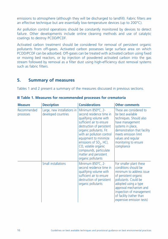
5. Summary of measures
Tables 1 and 2 present a summary of the measures discussed in previous sections.
� Table 1. Measures for recommended processes for crematoria
Measure Description Considerations Other comments
Recommendedprocesses
Large, new installations indeveloped countries
Minimum 850°C, 2-second residence time inqualifying volume withsufficient air to ensuredestruction of persistentorganic pollutants. Fitwith air pollution controlequipment to minimizeemissions of SO2, HCl,CO, volatile organiccompounds, particulatematter and persistentorganic pollutants
These are considered tobe best availabletechniques. Should alsohave managementsystems in place,demonstration that facilitymeets emission limitvalues and regularmonitoring to ensurecompliance
Small installations Minimum 850°C, 2-second residence time inqualifying volume withsufficient air to ensuredestruction of persistentorganic pollutants
For smaller plant theseconditions should beminimum to address issueof persistent organicpollutants. Could beadopted using a typeapproval mechanism andinspection of managementof facility (rather thanexpensive emission tests)
16 Guidelines on best available techniques and provisional guidance on best environmental practices
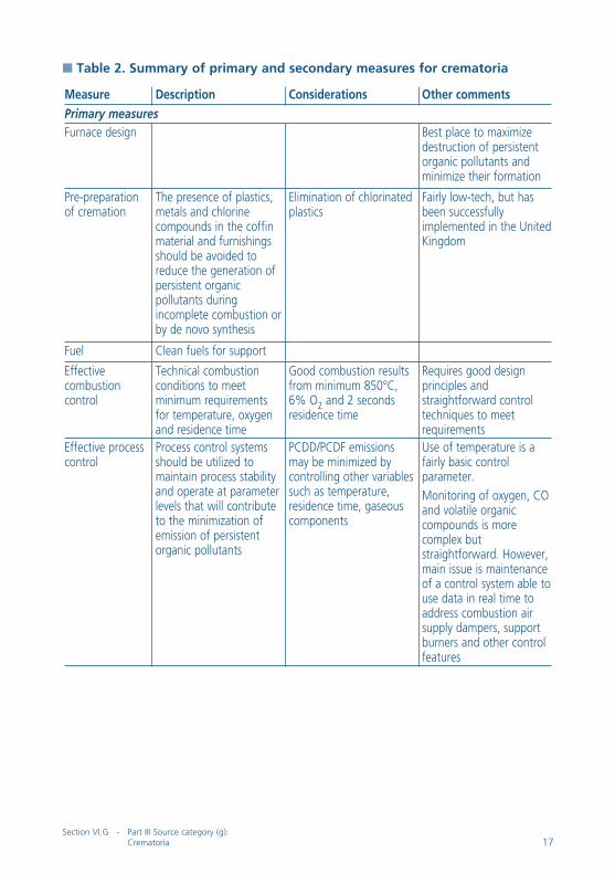
� Table 2. Summary of primary and secondary measures for crematoria
Measure Description Considerations Other comments
Primary measuresFurnace design Best place to maximize
destruction of persistentorganic pollutants andminimize their formation
Pre-preparationof cremation
The presence of plastics,metals and chlorinecompounds in the coffinmaterial and furnishingsshould be avoided toreduce the generation ofpersistent organicpollutants duringincomplete combustion orby de novo synthesis
Elimination of chlorinatedplastics
Fairly low-tech, but hasbeen successfullyimplemented in the UnitedKingdom
Fuel Clean fuels for support
Effectivecombustioncontrol
Technical combustionconditions to meetminimum requirementsfor temperature, oxygenand residence time
Good combustion resultsfrom minimum 850°C,6% O2 and 2 secondsresidence time
Requires good designprinciples andstraightforward controltechniques to meetrequirements
Effective processcontrol
Process control systemsshould be utilized tomaintain process stabilityand operate at parameterlevels that will contributeto the minimization ofemission of persistentorganic pollutants
PCDD/PCDF emissionsmay be minimized bycontrolling other variablessuch as temperature,residence time, gaseouscomponents
Use of temperature is afairly basic controlparameter.
Monitoring of oxygen, COand volatile organiccompounds is morecomplex butstraightforward. However,main issue is maintenanceof a control system able touse data in real time toaddress combustion airsupply dampers, supportburners and other controlfeatures
Section VI.G - Part III Source category (g):Crematoria 17

Measure Description Considerations Other comments
Operator training In-depth operator trainingcan be provided bycremator manufacturers ortrade organizationse.g. CrematoriumTechnicians TrainingScheme in operation inUnited Kingdom
Secondary measuresFume and gascollection
Effective containment offurnace gases in allconditions of thecremation process toavoid fugitive releases
Processes to beconsidered include sealedfurnaces to containfugitive emissions whilepermitting heat recoveryand collecting off-gases
Air pollutioncontrolequipment
Particulate matterabatement will helpreduce potential emissionof persistent organicpollutants.
Activated carbontreatment should beconsidered as thismaterial possesses largesurface area on whichPCDD/PCDF can beadsorbed from off-gases
Fabric filtration is themost effective particulatematter abatement and isconsistent with use ofdry/semi-dry sorbents foracid gas and metalscontrol. However, it willrequire a temperaturereduction.
Injection of powderedactivated carbon into thegas stream followed byremoval as a filter dust
Use of air pollution controldevices gives rise toadditional waste streamsand requires consumables.Likely need to reduce fluegas temperature (to avoiduse of more exoticfiltration media),consequently care neededto minimize residence inreformation window.
Better to avoid formationof persistent organicpollutants in the furnace.However, this approachallows some back-up forprocess upset conditionsand is considered a bestavailable technique inEurope for incinerationprocesses
18 Guidelines on best available techniques and provisional guidance on best environmental practices
6. Performance levels associated with best availabletechniques and best environmental practices
The performance level for air emissions of PCDD/PCDF from crematoria is <0.1 ng I-TEQ/Nm3. For combustion plant, these emission levels are expressed as massconcentrations at 11% oxygen, dry and standard temperature and pressure (0°C, 101.3kPa). As there is little consistent information available on PCB and HCB emissions fromcrematoria, it is unclear what emission levels can be achieved for these species.
Data from U.K. crematoria (Edwards 2001) for PCDD/PCDF range between 0.01 and0.12 ng I-TEQ/Nm3. Data for existing plant in France for PCDD/PCDF range between 0.1and 4.2 ng I-TEQ/Nm3 (Livolsi et al 2006). The average UNEP result at the Bangkokcrematoria (having a long brick flue duct) for PCDD/PCDF was 17.6 ng I_TEQ/Nm3
(Fiedler 2001). A survey of Korean crematoria has reported PCDD/PCDF concentrationsof 0.46 to 2.1 ng I-TEQ/Nm3 (Kim et al 2003).
References
Australasian Cemeteries and Crematoria Association. 2004. Cemetery Trust Manual. VictorianGovernment Department of Human Services, Public Health Division.
Edwards P. 2001. “Review of Emissions from Crematoria in the UK.” AEA Technology Report.Resurgam 44:81–128 and Pharos International 67:3.
Fiedler H. 2001. Thailand Dioxin Sampling and Analysis Program. Report by UNEP Chemicals incooperation with PCD, GTZ, Euro Chlor.
Kim D.H. et al. 2003. “Estimation of PCDDs, PCDFs and PAHs Emission from Crematories inKorea.” Organohalogen Compd. 63:9–12.
Livolsi B, Labrousse S. Baron P. Fiani E. (2006) “Dioxin emissions from French crematoria andassociated health impact” Organohalogen Compounds 68. In press.
notes
1 1 ng (nanogram) = 1 × 10-12 kilogram (1 × 10⁻⁹ gram). For information on toxicitymeasurement see section I.C, subsection 3 of the present guidelines.
Section VI.G - Part III Source category (g):Crematoria 19

http://www.pops.intUNEP/SSC/BATBEP/2008/12
Sect
ion
I-IV
Sect
ion
V.A
Sect
ion
V.B
Sect
ion
V.C
Sect
ion
V.D
Sect
ion
VI.A
Sect
ion
VI.B
Sect
ion
VI.C
Sect
ion
VI.D
Sect
ion
VI.E
Sect
ion
VI.F
Sect
ion
VI.G
Sect
ion
VI.H
Sect
ion
VI.I
Sect
ion
VI.J
Sect
ion
VI.K
Sect
ion
VI.L
Sect
ion
VI.M