Embed Size (px)
Citation preview
Benchmark Example No. 18
Creep and Shrinkage Calculation of a Rectangu-lar Prestressed Concrete CS
SOFiSTiK | 2022

VERiFiCATiONDCE-EN18 Creep and Shrinkage Calculation of a Rectangular Prestressed Concrete CS
VERiFiCATiON Manual, Service Pack 2022-3 Build 53
Copyright © 2022 by SOFiSTiK AG, Nuremberg, Germany.
SOFiSTiK AG
HQ Nuremberg Office Garching
Flataustraße 14 Parkring 2
90411 Nurnberg 85748 Garching bei Munchen
Germany Germany
T +49 (0)911 39901-0 T +49 (0)89 315878-0
F +49(0)911 397904 F +49 (0)89 315878-23
This manual is protected by copyright laws. No part of it may be translated, copied or reproduced, in any form or byany means, without written permission from SOFiSTiK AG. SOFiSTiK reserves the right to modify or to release
new editions of this manual.
The manual and the program have been thoroughly checked for errors. However, SOFiSTiK does not claim thateither one is completely error free. Errors and omissions are corrected as soon as they are detected.
The user of the program is solely responsible for the applications. We strongly encourage the user to test thecorrectness of all calculations at least by random sampling.
Front Cover
Arnulfsteg, Munich Photo: Hans Gossing
Creep and Shrinkage Calculation of a Rectangular Prestressed Concrete CS
Overview
Design Code Family(s): DIN
Design Code(s): DIN EN 1992-1-1
Module(s): AQB, CSM
Input file(s): creep shrinkage.dat
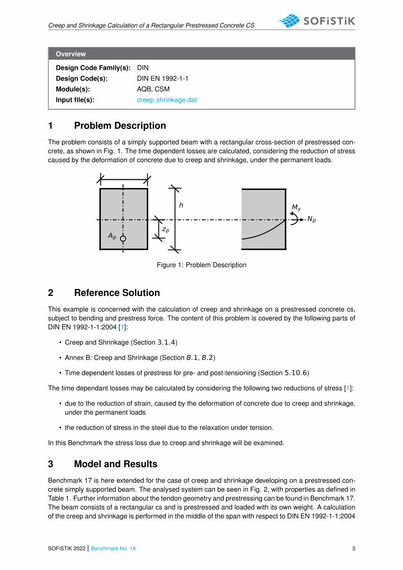
1 Problem Description
The problem consists of a simply supported beam with a rectangular cross-section of prestressed con-crete, as shown in Fig. 1. The time dependent losses are calculated, considering the reduction of stresscaused by the deformation of concrete due to creep and shrinkage, under the permanent loads.
My
Np
Ap
h
zp
Figure 1: Problem Description
2 Reference Solution
This example is concerned with the calculation of creep and shrinkage on a prestressed concrete cs,subject to bending and prestress force. The content of this problem is covered by the following parts ofDIN EN 1992-1-1:2004 [1]:
• Creep and Shrinkage (Section 3.1.4)
• Annex B: Creep and Shrinkage (Section B.1, B.2)
• Time dependent losses of prestress for pre- and post-tensioning (Section 5.10.6)
The time dependant losses may be calculated by considering the following two reductions of stress [1]:
• due to the reduction of strain, caused by the deformation of concrete due to creep and shrinkage,under the permanent loads
• the reduction of stress in the steel due to the relaxation under tension.
In this Benchmark the stress loss due to creep and shrinkage will be examined.
3 Model and Results
Benchmark 17 is here extended for the case of creep and shrinkage developing on a prestressed con-crete simply supported beam. The analysed system can be seen in Fig. 2, with properties as defined inTable 1. Further information about the tendon geometry and prestressing can be found in Benchmark 17.The beam consists of a rectangular cs and is prestressed and loaded with its own weight. A calculationof the creep and shrinkage is performed in the middle of the span with respect to DIN EN 1992-1-1:2004
SOFiSTiK 2022 | Benchmark No. 18 3
Creep and Shrinkage Calculation of a Rectangular Prestressed Concrete CS
(German National Annex) [1], [2]. The calculation steps [3] are presented below and the results aregiven in Table 2 for the calculation with AQB. For CSM only the results of the creep coefficients and thefinal losses are given, since the calculation is performed in steps.
Table 1: Model Properties
Material Properties Geometric Properties Loading (at = 10 m) Time
C 35/45 h = 100.0 cm Mg = 1250 kNm t0 = 28 dys
Y 1770 b = 100.0 cm Np = −3653.0 kN ts = 0 dys
RH = 80 L = 20.0 m teƒ ƒ = 1000000 dys
Ap = 28.5 cm2
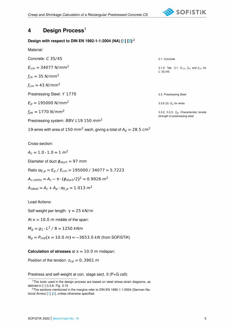
L
Figure 2: Simply Supported Beam
Table 2: Results
Result AQB CSM+AQB Ref.
εcs −18.85 · 10−5 - −18.85 · 10−5
ε −31.58 · 10−5 - −31.58 · 10−5
ϕ0 1.463 1.463 1.463
ϕ(t, t0) 1.393 1.393 1.393
Δσp,c+s [MP] −66.63 −67.30 −68.45
ΔPc+s [kN] 189.9 191.8 195.11
4 Benchmark No. 18 | SOFiSTiK 2022
Creep and Shrinkage Calculation of a Rectangular Prestressed Concrete CS
4 Design Process1
Design with respect to DIN EN 1992-1-1:2004 (NA) [1] [2]:2
Material:
Concrete: C 35/45 3.1: Concrete
Ecm = 34077 N/mm2 3.1.2: Tab. 3.1: Ecm, ƒck and ƒcm forC 35/45
ƒck = 35 N/mm2
ƒcm = 43 N/mm2
Prestressing Steel: Y 1770 3.3: Prestressing Steel
Ep = 195000 N/mm2 3.3.6 (3): Ep for wires
ƒpk = 1770 N/mm2 3.3.2, 3.3.3: ƒpk Characteristic tensilestrength of prestressing steel
Prestressing system: BBV L19 150 mm2
19 wires with area of 150mm2 each, giving a total of Ap = 28.5 cm2
Cross-section:
Ac = 1.0 · 1.0 = 1 m2
Diameter of duct ϕdct = 97 mm
Ratio αE,p = Ep / Ecm = 195000 / 34077 = 5.7223
Ac,netto = Ac − π · (ϕdct/2)2 = 0.9926 m2
Ade = Ac + Ap · αE,p = 1.013 m2
Load Actions:
Self weight per length: γ = 25 kN/m
At = 10.0 m middle of the span:
Mg = g1 · L2 / 8 = 1250 kNm
Np = Pm0( = 10.0 m) = −3653.0 kN (from SOFiSTiK)
Calculation of stresses at = 10.0 m midspan:
Position of the tendon: zcp = 0,3901 m
Prestress and self-weight at con. stage sect. 0 (P+G cs0)1The tools used in the design process are based on steel stress-strain diagrams, as
defined in [1] 3.3.6: Fig. 3.102The sections mentioned in the margins refer to DIN EN 1992-1-1:2004 (German Na-
tional Annex) [1], [2], unless otherwise specified.
SOFiSTiK 2022 | Benchmark No. 18 5
Creep and Shrinkage Calculation of a Rectangular Prestressed Concrete CS
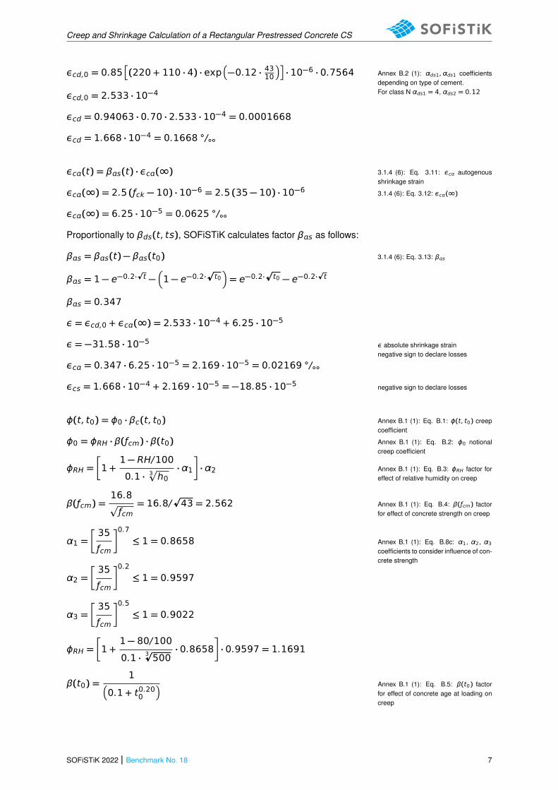
Np = −3653.0 kN and Mg = 1250 kNm
Mg + Mp
zp
Np
Pm0,=10
−σc
+σc
Mp1 = NP · zcp = −3653.0 · 0.3901 = −1425.04 kNmzs the new position of the center of thecross-section for cs0zp = zcp + zs
Mp2 = NP · zs = −3653.0 · 0.002978 = −10.879 kNm
Mp = −1425.04 − 10.879 = −1435.91 kNmMp bending moment caused by pre-stressing
My = 1250 − 1435.91 = −185.91 kNm
σc,QP =−3653.0
0.9926+−185.91
0.1633= −4.82 MPσc,QP stress in concrete
Calculation of creep and shrinkage at = 10.0 m midspan:
t0 = 28 dayst0 minimun age of concrete for loadingts age of concrete at start of dryingshrinkaget age of concrete at the moment consid-ered
ts = 0 days
t = teƒ ƒ + t0 = 1000000 + 28 = 1000028 days
εcs = εcd + εc3.1.4 (6): Eq. 3.8: εcs total shrinkagestrain
εcd(t) = βds(t, ts) · kh · εcd,03.1.4 (6): Eq. 3.9: εcd drying shrinkagestrain
The development of the drying shrinkage strain in time is strongly de-pends on βds(t, ts) factor. SOFiSTiK accounts not only for the age atstart of drying ts but also for the influence of the age of the prestressingt0. Therefore, the calculation of factor βds reads:
βds = βds(t, ts) − βds(t0, ts)3.1.4 (6): Eq. 3.10: βds
βds =(t − ts)
(t − ts) + 0.04 ·Ç
h30
−(t0 − ts)
(t0 − ts) + 0.04 ·Ç
h30
3.1.4 (6): h0 the notional size (mm) ofthe cs h0 = 2Ac/ = 500 mm
βds =(1000028 − 0)
(1000028 − 0) + 0.04 ·p
5003−
(28 − 0)
(28 − 0) + 0.04 ·p
5003
βds = 0.99955 − 0.05892 = 0.94063
kh = 0.70 for h0 ≥ 500 mm3.1.4 (6): Tab. 3.3: kh coefficient de-pending on h0
εcd,0 = 0.85�
(220 + 110 · αds1) · exp�
−αds2 ·ƒcmƒcmo
��
· 10−6 · βRHAnnex B.2 (1): Eq. B.11: εcd,0 basicdrying shrinkage strain
βRH = 1.55
�
1 −�
RH
RH0
�3�
= 1.55
�
1 −�
80
100
�3�
= 0.7564Annex B.2 (1): Eq. B.12: βRHRH the ambient relative humidity (%)
6 Benchmark No. 18 | SOFiSTiK 2022
Creep and Shrinkage Calculation of a Rectangular Prestressed Concrete CS
εcd,0 = 0.85�
(220 + 110 · 4) · exp�
−0.12 · 4310��
· 10−6 · 0.7564 Annex B.2 (1): αds1, αds1 coefficientsdepending on type of cement.For class N αds1 = 4, αds2 = 0.12εcd,0 = 2.533 · 10−4
εcd = 0.94063 · 0.70 · 2.533 · 10−4 = 0.0001668
εcd = 1.668 · 10−4 = 0.1668 ◦/◦◦
εc(t) = βs(t) · εc(∞) 3.1.4 (6): Eq. 3.11: εc autogenousshrinkage strain
εc(∞) = 2.5 (ƒck − 10) · 10−6 = 2.5 (35 − 10) · 10−6 3.1.4 (6): Eq. 3.12: εc(∞)
εc(∞) = 6.25 · 10−5 = 0.0625 ◦/◦◦
Proportionally to βds(t, ts), SOFiSTiK calculates factor βs as follows:
βs = βs(t) − βs(t0) 3.1.4 (6): Eq. 3.13: βs
βs = 1 − e−0.2·pt −
�
1 − e−0.2·pt0�
= e−0.2·pt0 − e−0.2·
pt
βs = 0.347
ε = εcd,0 + εc(∞) = 2.533 · 10−4 + 6.25 · 10−5
ε = −31.58 · 10−5 ε absolute shrinkage strainnegative sign to declare losses
εc = 0.347 · 6.25 · 10−5 = 2.169 · 10−5 = 0.02169 ◦/◦◦
εcs = 1.668 · 10−4 + 2.169 · 10−5 = −18.85 · 10−5 negative sign to declare losses
ϕ(t, t0) = ϕ0 · βc(t, t0) Annex B.1 (1): Eq. B.1: ϕ(t, t0) creepcoefficient
ϕ0 = ϕRH · β(ƒcm) · β(t0) Annex B.1 (1): Eq. B.2: ϕ0 notionalcreep coefficient
ϕRH =�
1 +1 − RH/100
0.1 · 3p
h0· α1
�
· α2 Annex B.1 (1): Eq. B.3: ϕRH factor foreffect of relative humidity on creep
β(ƒcm) =16.8p
ƒcm= 16.8/
p43 = 2.562 Annex B.1 (1): Eq. B.4: β(ƒcm) factor
for effect of concrete strength on creep
α1 =�
35
ƒcm
�0.7
≤ 1 = 0.8658 Annex B.1 (1): Eq. B.8c: α1, α2, α3coefficients to consider influence of con-crete strength
α2 =�
35
ƒcm
�0.2
≤ 1 = 0.9597
α3 =�
35
ƒcm
�0.5
≤ 1 = 0.9022
ϕRH =�
1 +1 − 80/100
0.1 · 3p500
· 0.8658�
· 0.9597 = 1.1691
β(t0) =1
�
0.1 + t0.200
� Annex B.1 (1): Eq. B.5: β(t0) factorfor effect of concrete age at loading oncreep
SOFiSTiK 2022 | Benchmark No. 18 7
Creep and Shrinkage Calculation of a Rectangular Prestressed Concrete CS
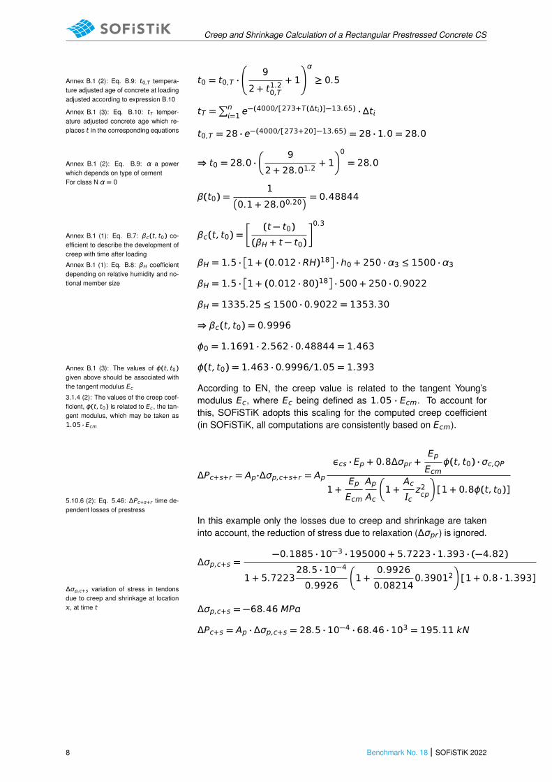
t0 = t0,T ·
9
2 + t1.20,T+ 1
!α
≥ 0.5Annex B.1 (2): Eq. B.9: t0,T tempera-ture adjusted age of concrete at loadingadjusted according to expression B.10
tT =∑n=1 e
−(4000/[273+T(Δt)]−13.65) · ΔtAnnex B.1 (3): Eq. B.10: tT temper-ature adjusted concrete age which re-places t in the corresponding equations t0,T = 28 · e−(4000/[273+20]−13.65) = 28 · 1.0 = 28.0
⇒ t0 = 28.0 ·�
9
2 + 28.01.2+ 1
�0
= 28.0Annex B.1 (2): Eq. B.9: α a powerwhich depends on type of cementFor class N α = 0
β(t0) =1
�
0.1 + 28.00.20� = 0.48844
βc(t, t0) =�
(t − t0)
(βH + t − t0)
�0.3
Annex B.1 (1): Eq. B.7: βc(t, t0) co-efficient to describe the development ofcreep with time after loading
βH = 1.5 ·�
1 + (0.012 · RH)18�
· h0 + 250 · α3 ≤ 1500 · α3Annex B.1 (1): Eq. B.8: βH coefficientdepending on relative humidity and no-tional member size βH = 1.5 ·
�
1 + (0.012 · 80)18�
· 500 + 250 · 0.9022
βH = 1335.25 ≤ 1500 · 0.9022 = 1353.30
⇒ βc(t, t0) = 0.9996
ϕ0 = 1.1691 · 2.562 · 0.48844 = 1.463
ϕ(t, t0) = 1.463 · 0.9996/1.05 = 1.393Annex B.1 (3): The values of ϕ(t, t0)given above should be associated withthe tangent modulus Ec3.1.4 (2): The values of the creep coef-ficient, ϕ(t, t0) is related to Ec, the tan-gent modulus, which may be taken as1.05 · Ecm
According to EN, the creep value is related to the tangent Young’smodulus Ec, where Ec being defined as 1.05 · Ecm. To account forthis, SOFiSTiK adopts this scaling for the computed creep coefficient(in SOFiSTiK, all computations are consistently based on Ecm).
ΔPc+s+r = Ap·Δσp,c+s+r = Apεcs · Ep + 0.8Δσpr +
Ep
Ecmϕ(t, t0) · σc,QP
1 +Ep
Ecm
Ap
Ac
�
1 +Ac
cz2cp
�
[1 + 0.8ϕ(t, t0)]5.10.6 (2): Eq. 5.46: ΔPc+s+r time de-pendent losses of prestress
In this example only the losses due to creep and shrinkage are takeninto account, the reduction of stress due to relaxation (Δσpr) is ignored.
Δσp,c+s =−0.1885 · 10−3 · 195000 + 5.7223 · 1.393 · (−4.82)
1 + 5.722328.5 · 10−4
0.9926
�
1 +0.9926
0.082140.39012
�
[1 + 0.8 · 1.393]Δσp,c+s variation of stress in tendonsdue to creep and shrinkage at location, at time t Δσp,c+s = −68.46 MP
ΔPc+s = Ap · Δσp,c+s = 28.5 · 10−4 · 68.46 · 103 = 195.11 kN
8 Benchmark No. 18 | SOFiSTiK 2022
Creep and Shrinkage Calculation of a Rectangular Prestressed Concrete CS
5 Conclusion
This example shows the calculation of the time dependent losses due to creep and shrinkage. It hasbeen shown that the results are in very good agreement with the reference solution.
6 Literature
[1] DIN EN 1992-1-1/NA: Eurocode 2: Design of concrete structures, Part 1-1/NA: General rules andrules for buildings - German version EN 1992-1-1:2005 (D), Nationaler Anhang Deutschland - StandFebruar 2010. CEN. 2010.
[2] F. Fingerloos, J. Hegger, and K. Zilch. DIN EN 1992-1-1 Bemessung und Konstruktion vonStahlbeton- und Spannbetontragwerken - Teil 1-1: Allgemeine Bemessungsregeln und Regeln furden Hochbau. BVPI, DBV, ISB, VBI. Ernst & Sohn, Beuth, 2012.
[3] Beispiele zur Bemessung nach Eurocode 2 - Band 1: Hochbau. Ernst & Sohn. Deutschen Beton-und Bautechnik-Verein E.V. 2011.
SOFiSTiK 2022 | Benchmark No. 18 9