Embed Size (px)
Citation preview
Creation of a narrow linewidth, high passive stability laser for
use in an ultra-cold strontium experiment
R. del Aguila
Dept. of Physics, University of Bath, BA2 7AY, UK
Email: [email protected]
Absract: An external cavity diode laser is created from a conventional laser diode following a
design proposed by Steck et al. with a view to creating a low-cost, stable laser system
operating at 689nm for use in an ultra-cold strontium experiment. The design uses a diffraction
grating in the Littrow configuration to achieve optical feedback into the laser diode and
stability is achieved by machining the laser cavity and grating arm from a single block of
aluminium, as well as temperature stabilisation and a stable current source, with purported
linewidth of kHz. The assembly process is documented and discussed. Through grating
alignment alone threshold current is reduced by up to 4mA demonstrating correct functioning
of the external cavity, however long-term wavelength stability is subject to temperature
fluctuations due to an unsuitable temperature control. Through tuning of the grating angle and
driving current a peak wavelength of 684.2nm was obtained. Although this figure could
increase with stable heating of the cavity, it is likely that the base wavelength of the diode
lasers is too far to practically tune the laser to the desired wavelength.
1. Background
The use of diode lasers in atomic physics experiments is well documented. Traditionally, laser sources
that could be matched to atomic transitions have been limited to tunable dye lasers. Improvements in
semiconductor laser diode fabrication have meant that tunable diode lasers can offer relatively
cheaper, more compact alternatives that offer excellent stability and require less power and hassle to
run. Further improvements in tunable diode laser design have meant that they are now well suited for
experiments with narrow atomic transitions.
At the Institute of Physics of Sao Carlos (Insituto de Física de Sao Carlos, IFSC) in Sao Paulo,
Brazil, there are two current experiments involving narrow atomic transitions in strontium. This
project, relevant to the second experiment which is still in initial stages, aims at creating a stable laser
system that will be used as part of a system to investigate the behaviour of ulta-cold strontium atoms
trapped in an optical lattice in a high-finesse ring cavity. The ultimate aim of the experiment is to use
the trapped ultra-cold strontium as a precision gravimeter.
In order to do this, the ring cavity needs to be locked to the atomic transition that is being
excited by the master laser creating the lattice. This ensures that the optical lattice, formed by a
standing wave inside the ring cavity, can react to changes in the atomic cloud that result from the
gravity measurements and the lattice is not lost. However, this cannot be done directly. Instead, a
probe laser which is locked to the ring cavity needs to be in turn phase locked to the master laser,
therefore resulting in the ring cavity being tuned to the atomic transition. The problem with this
approach is that the probe laser cannot interact with the atomic cloud, which would result in heating.
The probe laser can instead be locked to a longitudinal mode that is enough cavity free spectral ranges
away from the atomic transition that it will no longer interact with the atomic cloud, however it is not
possible to create a phase lock over this distance.[1] Instead, by using a narrow atomic transition and a
probe laser with a narrow linewidth, the probe laser can be locked to a longitudinal mode that is only
one or two free spectral ranges away, allowing a phase lock between the master and probe laser to
occur.
The purpose of this project is to create the probe laser that will be used to lock the master laser
to the ring cavity. The atomic transition used is the transition at 689nm [2], with a
transition linewidth of . Thus, the laser must have a similarly narrow linewidth at that
2
Creation of a narrow linewidth, high passive stability laser for use in an ultra-cold strontium experiment
wavelength. Furthermore, it should be highly stable in order to not disturb the fragile resonance of the
master laser with the atomic transition.
2. Theory
2.1 Tunable lasers and gratings
Tunable lasers are those for which the lasing frequency can be actively selected by the user over a
range. Solitary semiconductor diode lasers are tunable by varying driving current or operating
temperature, however solitary diode lasers are unsuitable for use in atomic experiments as they are
usually multimode and have large linewidths of the order of 10-20 MHz which makes it impossible to
tune them to the narrow atomic transitions that are of interest. Furthermore, although slightly tunable
their range is limited and subject to large mode hops as a consequence of the short cavity length.
These limitations can be surpassed by operating the laser diode in a setup which allows fine control
over lasing frequency and linewidth. On such method involves placing the laser diode in an external
lasing cavity, known as an External Cavity Diode Laser (ECDL).
The basic principle of operation involves having a laser diode with an anti-reflective coating at
one end of the optical cavity, allowing spontaneous and stimulated photons to escape into the external
cavity. Instead of reflecting all cavity modes back as in the case of a normal laser, the reflective end of
the external cavity is wavelength selective, meaning that only selected wavelengths will be reflected
back into the laser. If the diode is run slightly below threshold, lasing can occur at a specific reflected
wavelength, as only the selected wavelength will stimulate emission of photons inside the
semiconductor cavity, which will have the same properties as the photon stimulating the emission.
Wavelength selection at the end of the cavity can be achieved with the use of a diffraction grating.
There are two main grating configurations used to selectively filter wavelengths in an external
cavity: the Littman-Metcalf or grazing-incidence configuration and the Littrow configuration. In both
cases the angle of diffraction is wavelength dependent and is governed by the grating equation:
, (2.1) [3]
where a is the grating spacing, is the incident angle, is the diffracted angle and m is the order of
diffraction. In a Littrow configuration, the diffraction grating is blazed at an angle such that the angle
of incidence and angle of diffraction are the same , . The grating equation changes to become
. (2.2) [3]
The result of this is that the first order diffracted beam is reflected back along the incident beam. The
blazing angle is also chosen so that the grating efficiency results in approximately 20% of the incident
beam power reflected back along the incident beam and the majority of the remainder diffracted at the
second order angle. This means that by changing the angle of the grating relative to the beam, thereby
changing , one has narrowband selection over which wavelength is reflected back into the laser
diode. For the ECDL, the Littrow configuration is used over the grazing-incidence configuration as it
offers more output power.
2.2 The Steck ECDL
The laser design proposed by Steck et al. [4] makes modifications to traditional ECDL designs that
result in increased stability and linewidths as narrow as 10kHZ at 689nm, making it a suitable choice
for use in the locking scheme of the strontium experiment. The documentation for creation of a laser
is freely available from their website.[5]
The main difference in the Steck design from other commonly used ECDL designs is that the
entire laser cavity is machined from a single block of aluminium, from which an arm to hold the
diffraction grating is also machined. The arm is made to be as light and stiff as possible so that its
resonant frequency is well above that of background noise. In other ECDL designs the grating mount
3
Creation of a narrow linewidth, high passive stability laser for use in an ultra-cold strontium experiment
is usually separate to the main body housing the laser diode.[6] In the Steck design, the laser diode is
housed in a collimation can, and attached to the main body via a collimation can mount. This mount
has vertical tilt screws to adjust the vertical tilt of the beam, and also houses a 10K thermistor and
AD590 temperature sensor which for part of the temperature control system.
Diffraction angle is controlled via a fine adjust screw which pushes onto the back of the grating
arm. Further fine control is possible through use of a low voltage piezoelectric transducer (PZT)
which is sandwiched between the grating arm and fine adjust screw. In order to ensure good
mechanical contact between the screw and grating arm, the PZT has two sapphire discs epoxied at
either end of the stack to provide contact points.
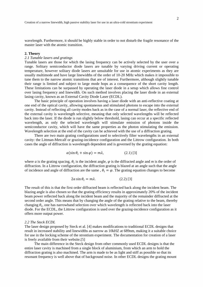
The output beam passes through a Brewster window into a small cavity with beam shaping
optics before leaving the main laser body through an optical isolator mounted onto the exterior of the
laser. The laser is intended to be coupled directly into a fibre at the output.
The laser cavity is designed to be vacuum sealed. Although relatively low vacuum will be used
( ), this increases stability of the laser by reducing thermal fluctuations within the laser cavity
which could affect the optical path length and therefore increase the linewidth of the laser. Figure 1
shows a schematic of the main cavity plate indicating the main components.
3. Assembly Procedure
Two identical laser systems are to be assembled, both with a cavity length of 10cm. Following the
designs available obtained from the Steck website, the laser bodies were machined in house at IFSC
by the machine shop. This also included machining of the collimation can mounts, optical isolator
mounts and a grating jig which aids installation of the diffraction grating at the correct position on the
grating arm.
3.1 Laser Diode Characterisation
Two important considerations in selecting an appropriate laser diode to be used for the ECDL are
threshold current and peak wavelength. The laser diodes used are Hitachi HL673MG AlGaInP diodes,
with manufacturer specified output power of 35mW and typical central wavelength of 690nm and
FIG 1. Schematic of main laser diode plate. Some important components are labelled. I Collimator can mount with can and
laser diode. II Diffraction grating mounted on grating arm. III Beam shaping optics. V & VI Fine adjust screw and PZT. XII
Beam output
4
Creation of a narrow linewidth, high passive stability laser for use in an ultra-cold strontium experiment
typical threshold current of 45mA.[7] A total of 6 diodes were characterised. Threshold current was
determined by using a power meter to plot total output power against driving current. At this juncture
only a rough comparison between diodes is necessary, so the prevalence of mode hops in the
multimode solitary laser diodes is expected and can be observed in the plotted graphs but does not
affect the threshold current significantly. Furthermore, the laser diodes were operated with no
focusing optics, which reduces the possibility that back reflections from the photodiode detector could
damage the device as reflected light would not be focused back into the laser cavity.
Likewise, for typical wavelength only a rough estimate is needed. This was obtained by
coupling the light from the naked diode into a wavemeter via a multi-mode fibre. In this setup, the
multimode nature and temperature sensitivity of the solitary diode is very apparent as the detected
wavelength hops clearly between modes. To compare typical wavelengths, all diodes were initially
operated at the same driving current, followed by small ( ) adjustments to find a semi-stable
mode, recorded as the peak wavelength.
3.2 Setup of the thermal baseplate
Cooling and heating of the thermal cavity is done through use of a baseplate that acts as a heatsink
and is thermally isolated from the laser cavity. Temperature is controlled with the use of three
thermoelectric coolers connected in series that bridge the gap between the baseplate and main body of
the laser. The coolers operate by the Peltier effect; passing a DC current through the device results in
one side becoming hot and the opposite cold. Reversing the polarity of the current inverts the hot and
cold sides, allowing the cooler to act as a temperature control.
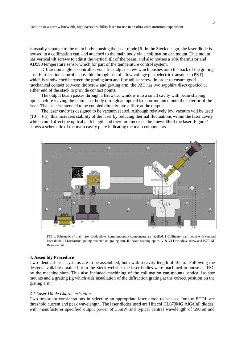
It is important to ensure good thermal contact between the thermoelectric coolers and the plates
of the laser. This is achieved by applying a very thin, even layer of thermal paste on the cooler to fill
out any microscopic air gapes that may exist at the interface between the cooler and the laser plates,
thus increasing thermal conductivity.
.
Although the current supplied to the thermoelectric coolers is ultimately supplied by a PID
current controller, preliminary testing to ensure adequate response and determine possible maximum
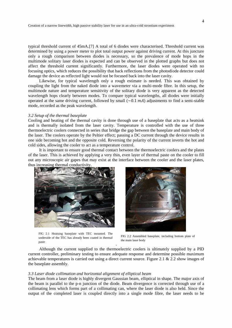
achievable temperatures is carried out using a direct current source. Figure 2.1 & 2.2 show images of
the baseplate assembly.
3.3 Laser diode collimation and horizontal alignment of elliptical beam
The beam from a laser diode is highly divergent Gaussian beam, elliptical in shape. The major axis of
the beam is parallel to the p-n junction of the diode. Beam divergence is corrected through use of a
collimating lens which forms part of a collimating can, where the laser diode is also held. Since the
output of the completed laser is coupled directly into a single mode fibre, the laser needs to be
FIG 2.1 Heatsing baseplate with TEC mounted. The
underside of the TEC has already been coated in thermal
paste
FIG 2.2 Assembled baseplate, including bottom plate of
the main laser body
5
Creation of a narrow linewidth, high passive stability laser for use in an ultra-cold strontium experiment
collimated by a distance of at least twice the optical round trip inside the laser. In practice, the laser
diodes were collimated over a distance of approximately 7 metres.
After collimation the beam is still elliptical in shape. This is corrected with the use of an
anamorphic prism pair placed after the Brewster window, which reshapes the beam into one with a
circular cross section with no change of direction, although the beam position is laterally shifted. In
order to ensure both correct beam shaping and maximum diffraction efficiency from the grating, the
major axis of the beam must be aligned perfectly with the horizontal axis.
In order to achieve this, advantage is taken of the fact that the output of laser diodes is polarised
parallel to the minor axis of the elliptical beam. This is due to fact that the TE mode of the diode,
which is perpendicular to the junction, is more strongly guided than the TM mode. In order to align
the major axis of the beam horizontally, the collimated beam is passed through a polarising beam
splitter, which reflects vertically polarised light and transmits horizontally polarised light. The
transmitted optical power is measured with a power meter. As the collimation can is rotated the ratio
of transmitted to reflected power changes due to alignment of the polarisation. When the power
transmitted through the beam splitter is at a minimum, the polarization of the beam is vertically
aligned and therefore the major axis of the beam is aligned with the horizontal.
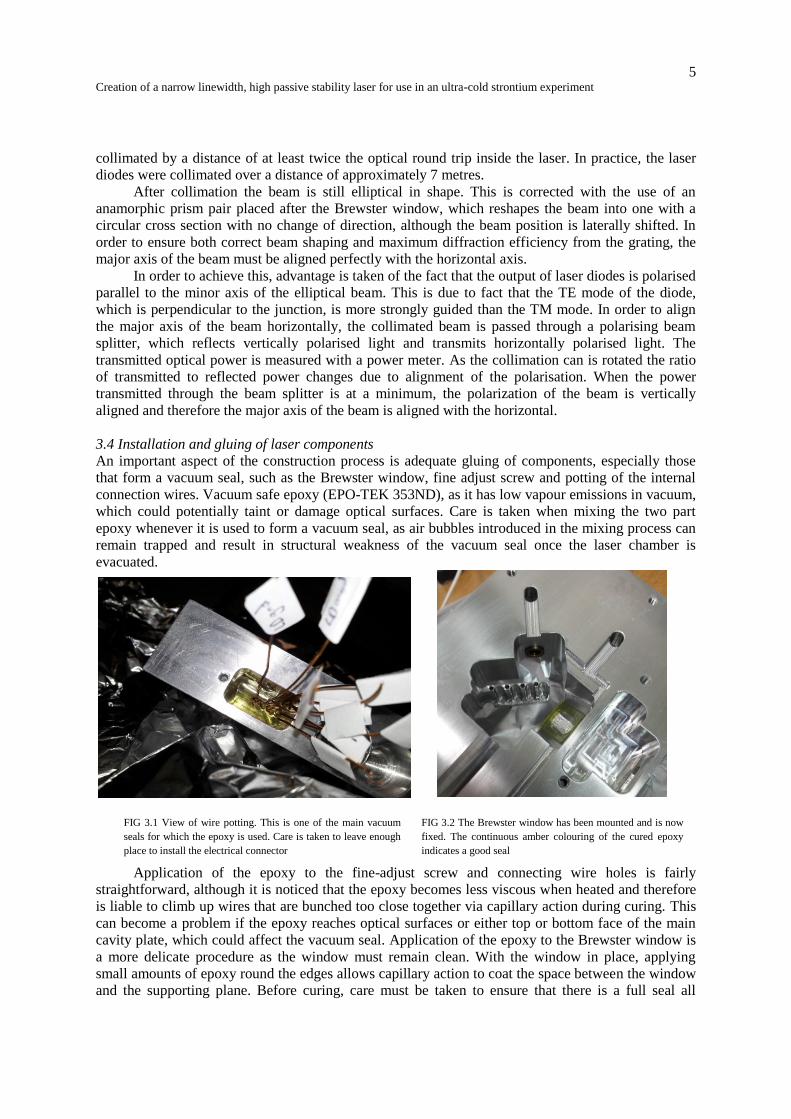
3.4 Installation and gluing of laser components
An important aspect of the construction process is adequate gluing of components, especially those
that form a vacuum seal, such as the Brewster window, fine adjust screw and potting of the internal
connection wires. Vacuum safe epoxy (EPO-TEK 353ND), as it has low vapour emissions in vacuum,
which could potentially taint or damage optical surfaces. Care is taken when mixing the two part
epoxy whenever it is used to form a vacuum seal, as air bubbles introduced in the mixing process can
remain trapped and result in structural weakness of the vacuum seal once the laser chamber is
evacuated.
Application of the epoxy to the fine-adjust screw and connecting wire holes is fairly
straightforward, although it is noticed that the epoxy becomes less viscous when heated and therefore
is liable to climb up wires that are bunched too close together via capillary action during curing. This
can become a problem if the epoxy reaches optical surfaces or either top or bottom face of the main
cavity plate, which could affect the vacuum seal. Application of the epoxy to the Brewster window is
a more delicate procedure as the window must remain clean. With the window in place, applying
small amounts of epoxy round the edges allows capillary action to coat the space between the window
and the supporting plane. Before curing, care must be taken to ensure that there is a full seal all
FIG 3.1 View of wire potting. This is one of the main vacuum
seals for which the epoxy is used. Care is taken to leave enough
place to install the electrical connector
FIG 3.2 The Brewster window has been mounted and is now
fixed. The continuous amber colouring of the cured epoxy
indicates a good seal
6
Creation of a narrow linewidth, high passive stability laser for use in an ultra-cold strontium experiment
around the window opening. Figures 3.1 and 3.2 show images of potting of the connecting wires and
installation of the Brewster window.
Vacuum safe epoxy is also used to attach the sapphire discs to the grating PZT. The technique
used is similar to the one used for the Brewster window. The epoxy can also be used to set the
thermistor and AD590 into their respective holes in the collimation can mount.
Manufacturer data sheets recommend curing the epoxy at 80º for 30 minutes. However, due to
the thermal mass of the aluminium cavity it was found that proper curing only occurred after 2 hours.
Importantly, installation and curing of all components that require vacuum safe epoxy must be done
before grating installation, as any possible vapours released when the epoxy is heated could damage
the delicate surface of the grating.
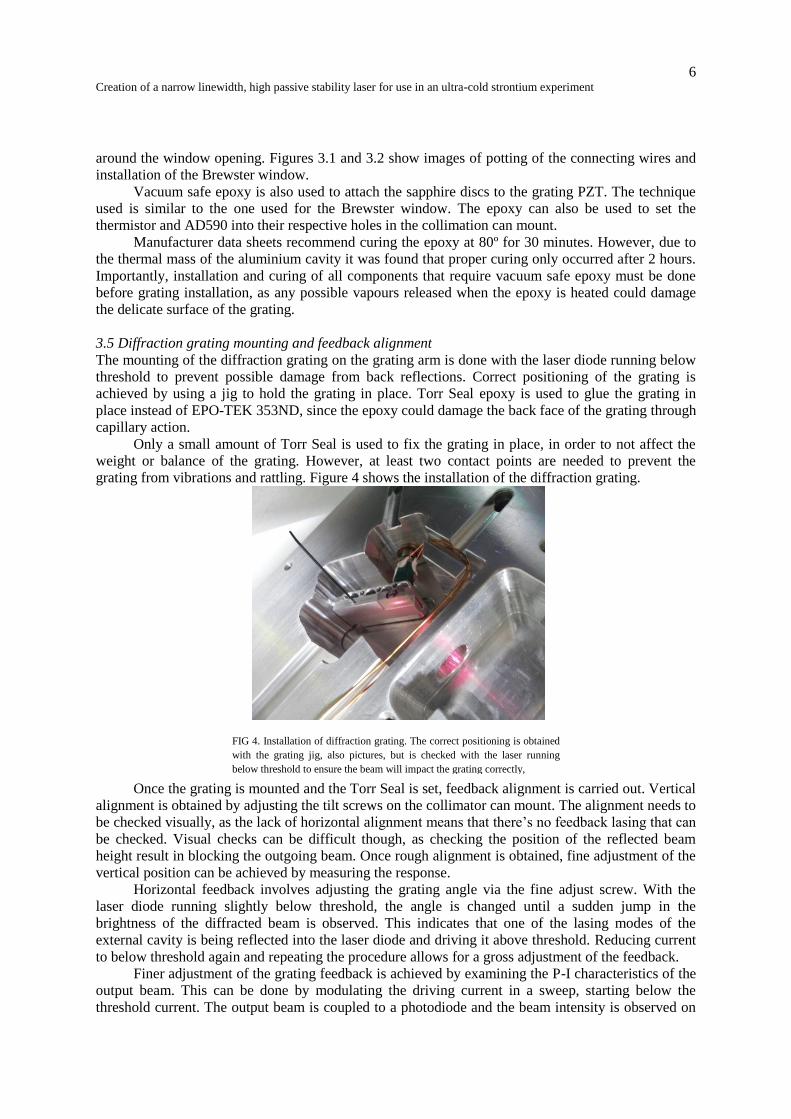
3.5 Diffraction grating mounting and feedback alignment
The mounting of the diffraction grating on the grating arm is done with the laser diode running below
threshold to prevent possible damage from back reflections. Correct positioning of the grating is
achieved by using a jig to hold the grating in place. Torr Seal epoxy is used to glue the grating in
place instead of EPO-TEK 353ND, since the epoxy could damage the back face of the grating through
capillary action.
Only a small amount of Torr Seal is used to fix the grating in place, in order to not affect the
weight or balance of the grating. However, at least two contact points are needed to prevent the
grating from vibrations and rattling. Figure 4 shows the installation of the diffraction grating.
Once the grating is mounted and the Torr Seal is set, feedback alignment is carried out. Vertical
alignment is obtained by adjusting the tilt screws on the collimator can mount. The alignment needs to
be checked visually, as the lack of horizontal alignment means that there’s no feedback lasing that can
be checked. Visual checks can be difficult though, as checking the position of the reflected beam
height result in blocking the outgoing beam. Once rough alignment is obtained, fine adjustment of the
vertical position can be achieved by measuring the response.
Horizontal feedback involves adjusting the grating angle via the fine adjust screw. With the
laser diode running slightly below threshold, the angle is changed until a sudden jump in the
brightness of the diffracted beam is observed. This indicates that one of the lasing modes of the
external cavity is being reflected into the laser diode and driving it above threshold. Reducing current
to below threshold again and repeating the procedure allows for a gross adjustment of the feedback.
Finer adjustment of the grating feedback is achieved by examining the P-I characteristics of the
output beam. This can be done by modulating the driving current in a sweep, starting below the
threshold current. The output beam is coupled to a photodiode and the beam intensity is observed on
FIG 4. Installation of diffraction grating. The correct positioning is obtained
with the grating jig, also pictures, but is checked with the laser running
below threshold to ensure the beam will impact the grating correctly,
7
Creation of a narrow linewidth, high passive stability laser for use in an ultra-cold strontium experiment
an oscilloscope. This allows the threshold current and mode structure as a function of driving current
to be observed for selected grating angles, which can then be optimised with the fine adjust screw and
the tilt adjust screws on the collimator can mount. Good response on the oscilloscope is obtained
when the current is modulated at approximately 50Hz, although in principle the frequency of
modulation makes no difference.
A beam splitter cube is placed before the photodiode, and the refracted beam is coupled to a
wavemeter via a multimode fibre, allowing measurement of the peak wavelength. When a good
response on the P-I curve is obtained, the modulation is switched off and the driving current is set
above threshold to examine the obtained frequency. It is important to prevent back reflections from
affecting the laser diode by use of an optical isolator as close to the beam output as possible.
4. Results 4.1 Laser Diode Characterisation
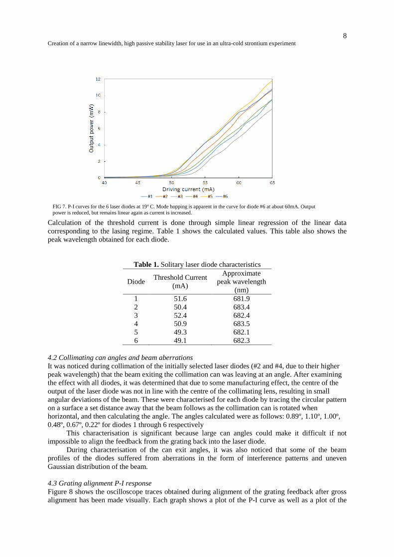
The characteristic P-I curve of all six solitary diodes are show in Figure 7. All six curves show the
two separate regimes, lasing and non-lasing. For laser diodes, even though photon density within the
cavity increases exponentially above threshold, output power is expected to increase linearly. This is
observed although the curve for diode #6 shows a drop in power at a higher driving current. Although
this , corresponding to a mode hop. However, this does not affect the threshold current that can be
calculated.
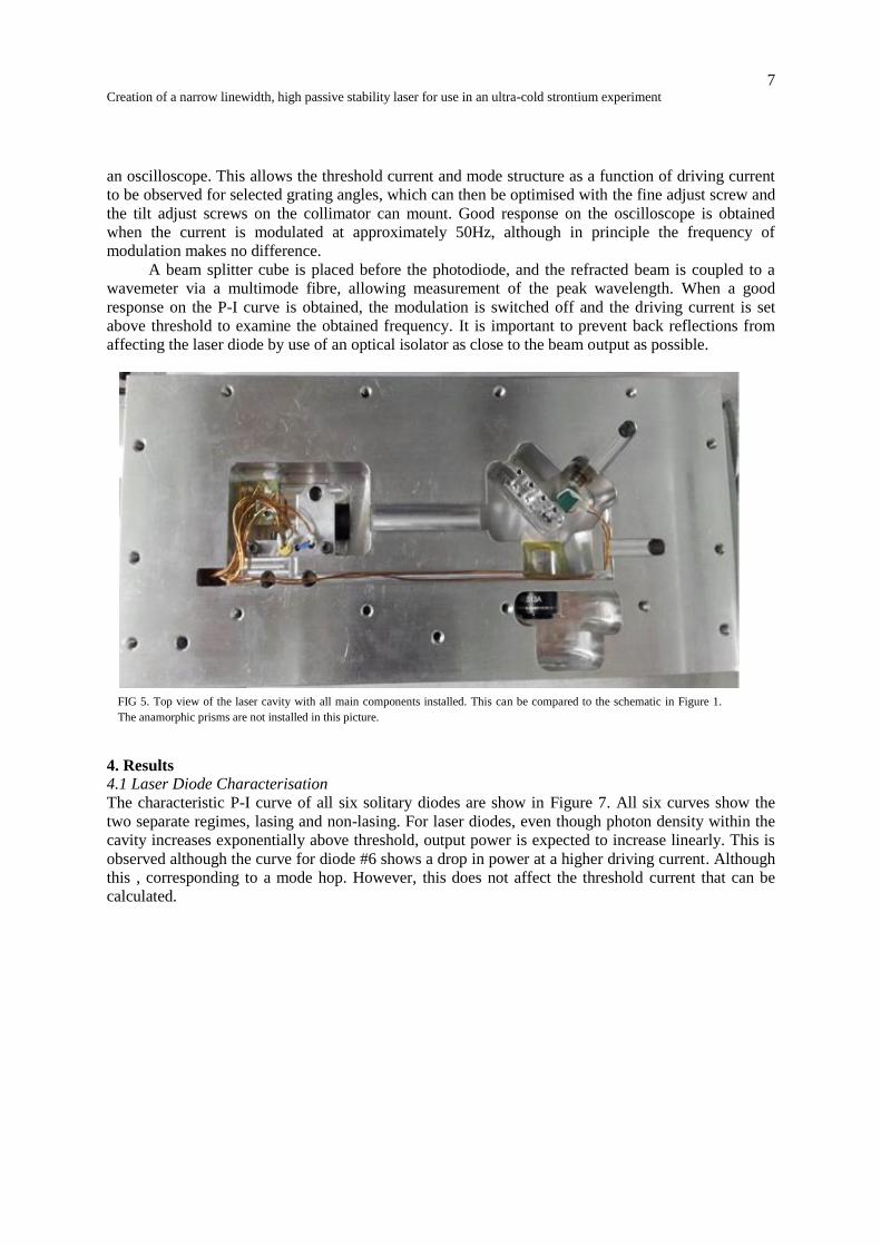
FIG 5. Top view of the laser cavity with all main components installed. This can be compared to the schematic in Figure 1.
The anamorphic prisms are not installed in this picture.
8
Creation of a narrow linewidth, high passive stability laser for use in an ultra-cold strontium experiment
Calculation of the threshold current is done through simple linear regression of the linear data
corresponding to the lasing regime. Table 1 shows the calculated values. This table also shows the
peak wavelength obtained for each diode.
Table 1. Solitary laser diode characteristics
Diode Threshold Current
(mA)
Approximate
peak wavelength
(nm)
1 51.6 681.9
2 50.4 683.4
3 52.4 682.4
4 50.9 683.5
5 49.3 682.1
6 49.1 682.3
4.2 Collimating can angles and beam aberrations
It was noticed during collimation of the initially selected laser diodes (#2 and #4, due to their higher
peak wavelength) that the beam exiting the collimation can was leaving at an angle. After examining
the effect with all diodes, it was determined that due to some manufacturing effect, the centre of the
output of the laser diode was not in line with the centre of the collimating lens, resulting in small
angular deviations of the beam. These were characterised for each diode by tracing the circular pattern
on a surface a set distance away that the beam follows as the collimation can is rotated when
horizontal, and then calculating the angle. The angles calculated were as follows: 0.89º, 1.10º, 1.00º,
0.48º, 0.67º, 0.22º for diodes 1 through 6 respectively
This characterisation is significant because large can angles could make it difficult if not
impossible to align the feedback from the grating back into the laser diode.
During characterisation of the can exit angles, it was also noticed that some of the beam
profiles of the diodes suffered from aberrations in the form of interference patterns and uneven
Gaussian distribution of the beam.
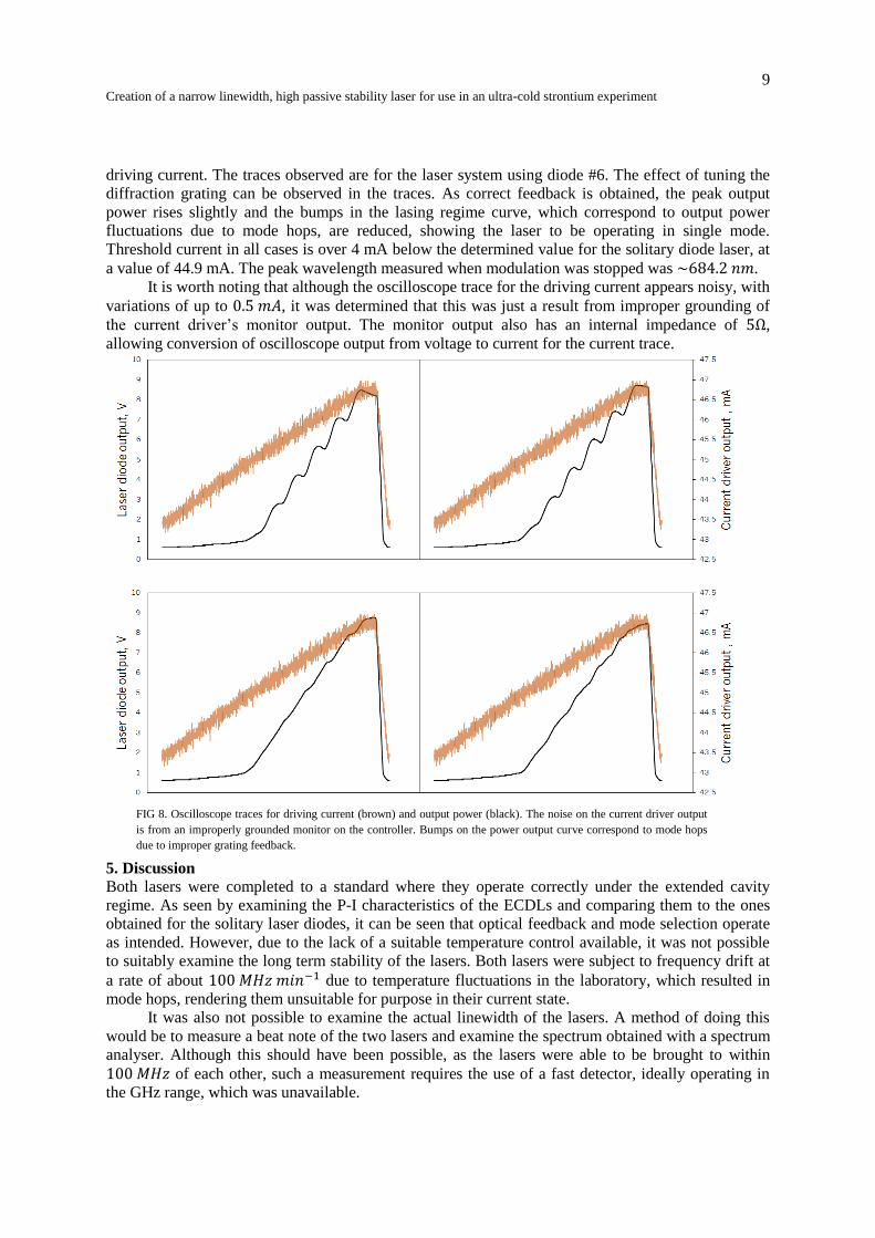
4.3 Grating alignment P-I response
Figure 8 shows the oscilloscope traces obtained during alignment of the grating feedback after gross
alignment has been made visually. Each graph shows a plot of the P-I curve as well as a plot of the
FIG 7. P-I curves for the 6 laser diodes at 19º C. Mode hopping is apparent in the curve for diode #6 at about 60mA. Output
power is reduced, but remains linear again as current is increased.
9
Creation of a narrow linewidth, high passive stability laser for use in an ultra-cold strontium experiment
driving current. The traces observed are for the laser system using diode #6. The effect of tuning the
diffraction grating can be observed in the traces. As correct feedback is obtained, the peak output
power rises slightly and the bumps in the lasing regime curve, which correspond to output power
fluctuations due to mode hops, are reduced, showing the laser to be operating in single mode.
Threshold current in all cases is over 4 mA below the determined value for the solitary diode laser, at
a value of 44.9 mA. The peak wavelength measured when modulation was stopped was .
It is worth noting that although the oscilloscope trace for the driving current appears noisy, with
variations of up to , it was determined that this was just a result from improper grounding of
the current driver’s monitor output. The monitor output also has an internal impedance of ,
allowing conversion of oscilloscope output from voltage to current for the current trace.
5. Discussion
Both lasers were completed to a standard where they operate correctly under the extended cavity
regime. As seen by examining the P-I characteristics of the ECDLs and comparing them to the ones
obtained for the solitary laser diodes, it can be seen that optical feedback and mode selection operate
as intended. However, due to the lack of a suitable temperature control available, it was not possible
to suitably examine the long term stability of the lasers. Both lasers were subject to frequency drift at
a rate of about due to temperature fluctuations in the laboratory, which resulted in
mode hops, rendering them unsuitable for purpose in their current state.
It was also not possible to examine the actual linewidth of the lasers. A method of doing this
would be to measure a beat note of the two lasers and examine the spectrum obtained with a spectrum
analyser. Although this should have been possible, as the lasers were able to be brought to within
of each other, such a measurement requires the use of a fast detector, ideally operating in
the GHz range, which was unavailable.
FIG 8. Oscilloscope traces for driving current (brown) and output power (black). The noise on the current driver output
is from an improperly grounded monitor on the controller. Bumps on the power output curve correspond to mode hops
due to improper grating feedback.
10
Creation of a narrow linewidth, high passive stability laser for use in an ultra-cold strontium experiment
Although it was not possible to make the lasers stable, there is evidence to suggest that the goal
of operating the laser at 689nm would not be possible using the current setup. Difficulties with the
laser diodes themselves, particularly optical aberrations and undesirable output angles from the
collimation can meant that the diodes selected for use were #6 and #4. Ideally, the starting frequency
of the laser diode would be as close as possible to the desired frequency, to limit the amount of tuning
that needs to be done. It may be possible that this could be corrected with the finalization of a suitable
PID temperature control (which would also result in a stable laser) as the laser could be heated to
increase the wavelength. The manufacturer states an increase in wavelength of 1nm per every 4
degree increase in temperature. However, as this would necessitate at least a 20º temperature increase
and given the thermal mass of the completed laser, this is not likely to be feasible.
It is apparent that all six laser diodes come from the same batch, given the similarities in
solitary diode threshold current and lasing wavelength, given that the manufacturer quotes their
ranges respectively as being 40mA and 15nm.[7] A solution that was not available due to time
constraints would have been to return the laser diodes to the supplier and request diodes from a range
of batches, to ensure a better spread of initial parameters. Starting with a solitary diode with a
wavelength closer to the desired wavelength of 689 would at ensure that once wavelength stability is
obtained, the desired wavelength would be within the tunable range of the ECDL.
6. Conclusions
Despite not achieving the desired wavelength or stability needed for use in the ring cavity locking
experiment, big steps have been made towards this goal. As the majority of the laser components are
installed and functioning correctly, the next goal is to achieve stable wavelength lasing from the
ECDL once a suitable temperature controller is available, as well as obtain fine control of grating
angle through use of the PZT. However, these objectives may have to be delayed until new laser
diodes are sourced with solitary peak wavelengths closer to 689nm.
Linewidth characterisation should also be completed when a suitably fast detector is available
to ensure that the linewidth of the laser is narrow enough. The system is set up for vacuum seal, but it
may be possible to operate the lasers suitably without them if need be, as sourcing a suitable vacuum
system is likely to be time consuming given the difficulty of obtaining components in Brazil.
7. Acknowledgements The author would like to thank first and foremost Prof. Philippe W. Courteille for the opportunity of
undertaking this project as part of his group and pastoral support offered during the course of the
placement. Deep thanks are also extended to Dr. Michael Holynski and Paulo H. Moriya, for their
invaluable help in the laboratory, suggesting theoretical background material, teaching of new
experimental and practical techniques and patience, without which this project could not have been
undertaken. Thanks also to Faizah Rafique for scientific discussions and to Marina Samoylova for
moral support throughout the placement.
References
[1] Holynski, M. (2013). Travamento de uma cavidade em anel para átomo frio utilizando uma
transição estreita, CNPq Project Proposal, IFSC
[2] Huang, B. (2009) Linewidth Reduction of a Diode Laserby Optical Feedbackfor Strontium BEC
Applications, Master’s thesis, University of Innsbruck (available online at
http://strontiumbec.com/StrontiumLab/Theses/Bo_Huang_master_thesis.pdf, last accessed January
2014)
[3] Zorabedian, P. (1995). Tunable Lasers Handbook. Edited by Duarte F.J. (Burlington Academic
Press)
[4] Cook, E.C. Martin, P.J. Brown-Heft, T.L. Garman, J.C. and Steck, D.A. (2012). Rev. Sci. Ins. 83,
10.1063/1.3698003

11
Creation of a narrow linewidth, high passive stability laser for use in an ultra-cold strontium experiment
[5] Steck Lab Website (http://atomoptics.uoregon.edu/unilaser/, last accessed January 2014)
[6] Weiman, C.E. Hollberg, L. (1990). Rev. Sci. Ins. 62, 10.1063/1.1142305
[7] Hitachi (2005), Component Data Sheet, (available online at
http://atomoptics.uoregon.edu/unilaser/unibody_files/peripherals/laser_diodes/689nm_diode.pdf, last
accessed September 2013)