Embed Size (px)
Citation preview
1
Creating Virtual Worlds with a Graspable User InterfaceHauke Ernst Kai Schäfer Willi Bruns
Research Center Work and Technology (artec)University of Bremen
Enrique Schmidt Str. (SFG)28334 Bremen, Germany
{ernst | schaefer | bruns}@artec.uni-bremen.de
ABSTRACT
We introduce a system to interact with computersusing real objects as interface. The graspable modelon the table has a congruent counterpart in the com-puter which is updated continuously. The use ofconcrete objects offers advantages for interactionand cooperation. The underlying virtual model pro-vides capabilities like remote visualization, simula-tion and documentation which play an importantrole for processes in engineering and education.System implementation, interaction concepts, proj-ects as well as the impact on distant cooperation areintroduced in this article.
Keywords: real reality, graspable user interfaces,image recognition, data gloves, multimodal ac-cess, cooperation
1 INTRODUCTION
This document gives a description of selected as-pects which become interesting when computer rep-resentations and its functionality are automaticallyallocated to physical models. This is of relevance toour research projects where we use physical modelsas an intuitive interface for computer based model-ing. We introduce two of our applications that usethis concept in two different scopes and explain af-terwards the technologic basis of our systems in-cluding an overview over the system architecture.Moreover, we will compare real world interactionswith language processing. Additionally, we willidentify open questions for the application of theconcept in distant cooperative environments andpropose mechanisms for solutions.
By bridging the gap between the real and the virtualworld we are in a position to overcome some of thedifficulties which obstruct the computer based mod-eling. This is generally characterized by its interfacetechnology like monitor, keyboard and mouse, inVirtual Reality applications Head Mounted Displays,
Data Gloves and other n-dimensional input devices.These techniques in general obstruct communica-tion, don’t allow direct grasping with appropriatesensual feedback and deliverer a more or less in-complete representation of the model to the user.The application of concrete components gives theuser the feeling and the experience of the real world.The use of 3D visualization and schematic repre-sentations creates links between the concrete andabstract concepts required for learning. The applica-tion of computer technology means that for instancevisual, schematic and acoustic information can bemade available to the user. Once we have generateda virtual world we can attach properties to the ob-jects which allow us to simulate their functionalitywithin the virtual model or to export them to off-the-shelf simulators. In order to achieve a bridge be-tween these different media a new interface is re-quired which is able to translate the construction ofa concrete world into an abstract representation.This combines a multimodal access to virtual envi-ronments with a normal communication betweenpeople in the real world.
We use two different technologies to synchronize theposition of the real objects with the positions of thevirtual ones. The first one applies image recognitionto detect and locate the real world objects using sim-ple, fast and robust technologies. The second oneuses magnetic trackers attached to the users hand.Monitoring the actions of the hands allows the syn-chronization of the position and also the movementsof real and virtual objects. This approach allows therealization of modeling and demonstration processesfor creating and programming virtual worlds. Wesummarize these concepts under the name Real Re-ality.
Published in: 15th Twente Workshop on LanguageTechnology (TWTL 15): Interactions in VirtualWorlds. Nijholt, A.; Donk, O.; Dijk, B. (Eds.).University of Twente, NL, 1999
2
2 APPLICATIONS
2.1 APPLICATION IN VOCATIONALTRAINING OF PNEUMATICS
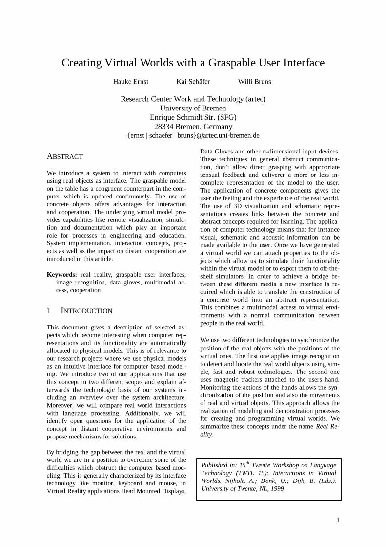
After a couple of national projects which provide thetheoretical background and the basic technology forour Real Reality concept we are now in the secondyear of the more product-oriented European (ES-PRIT and Leonardo) project BREVIE: Bridging Re-ality and Virtuality with a Graspable User Interface.The BREVIE project aims at designing, developingand evaluating a new kind of teaching and learningenvironment in the field of vocational training inpneumatics. The main characteristic of this envi-ronment is to provide transitions and links betweentwo worlds which are currently separated:the physical pneumatic circuit which can be graspedand touched with our hands, and the world of ab-stract models which can be viewed on paper or on acomputer screen. The links are achieved by a"Graspable User Interface" which enables students towork and learn in both of these worlds (Fig. 1).In the vocational training for pneumatics severalkinds of learning material for teaching can be found.For the project consortium, the most compelling isthe very popular pneumatic construction kit of ourpartner Festo Didactic which can be used for build-ing functional pneumatic circuits. These circuitswork with compressed air and allow a very closerepresentation of real production environments.The project makes use of these construction kits anddevelops technical links - through the GraspableUser Interface - to computer-based learning media.In the BREVIE project we use two low cost videocameras and image recognition algorithms to syn-chronize the physical model with a virtual model
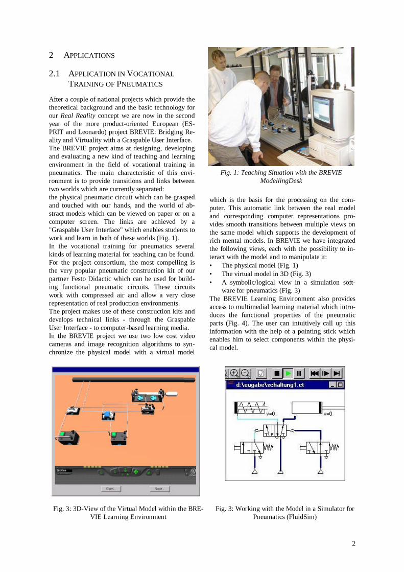
which is the basis for the processing on the com-puter. This automatic link between the real modeland corresponding computer representations pro-vides smooth transitions between multiple views onthe same model which supports the development ofrich mental models. In BREVIE we have integratedthe following views, each with the possibility to in-teract with the model and to manipulate it:• The physical model (Fig. 1)• The virtual model in 3D (Fig. 3)• A symbolic/logical view in a simulation soft-
ware for pneumatics (Fig. 3)The BREVIE Learning Environment also providesaccess to multimedial learning material which intro-duces the functional properties of the pneumaticparts (Fig. 4). The user can intuitively call up thisinformation with the help of a pointing stick whichenables him to select components within the physi-cal model.
Fig. 1: Teaching Situation with the BREVIEModellingDesk
Fig. 3: 3D-View of the Virtual Model within the BRE-VIE Learning Environment
Fig. 3: Working with the Model in a Simulator forPneumatics (FluidSim)
3
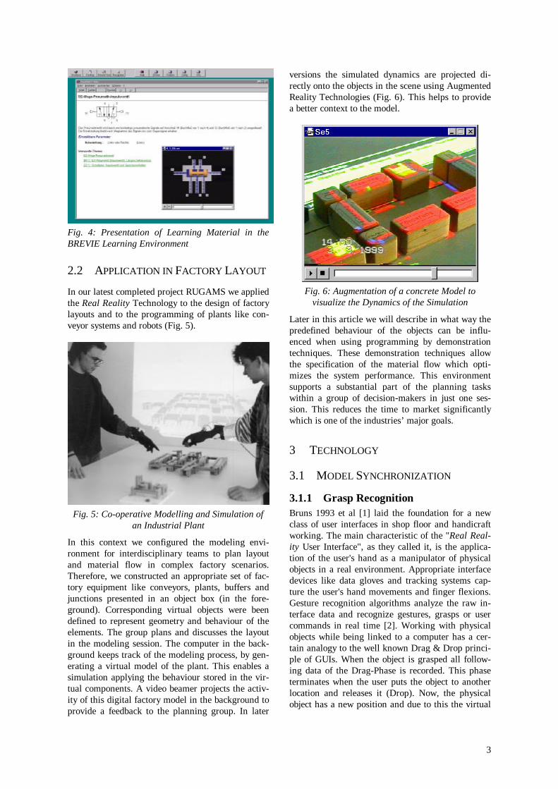
Fig. 4: Presentation of Learning Material in theBREVIE Learning Environment
2.2 APPLICATION IN FACTORY LAYOUT
In our latest completed project RUGAMS we appliedthe Real Reality Technology to the design of factorylayouts and to the programming of plants like con-veyor systems and robots (Fig. 5).
Fig. 5: Co-operative Modelling and Simulation ofan Industrial Plant
In this context we configured the modeling envi-ronment for interdisciplinary teams to plan layoutand material flow in complex factory scenarios.Therefore, we constructed an appropriate set of fac-tory equipment like conveyors, plants, buffers andjunctions presented in an object box (in the fore-ground). Corresponding virtual objects were beendefined to represent geometry and behaviour of theelements. The group plans and discusses the layoutin the modeling session. The computer in the back-ground keeps track of the modeling process, by gen-erating a virtual model of the plant. This enables asimulation applying the behaviour stored in the vir-tual components. A video beamer projects the activ-ity of this digital factory model in the background toprovide a feedback to the planning group. In later
versions the simulated dynamics are projected di-rectly onto the objects in the scene using AugmentedReality Technologies (Fig. 6). This helps to providea better context to the model.
Fig. 6: Augmentation of a concrete Model tovisualize the Dynamics of the Simulation
Later in this article we will describe in what way thepredefined behaviour of the objects can be influ-enced when using programming by demonstrationtechniques. These demonstration techniques allowthe specification of the material flow which opti-mizes the system performance. This environmentsupports a substantial part of the planning taskswithin a group of decision-makers in just one ses-sion. This reduces the time to market significantlywhich is one of the industries’ major goals.
3 TECHNOLOGY
3.1 MODEL SYNCHRONIZATION
3.1.1 Grasp RecognitionBruns 1993 et al [1] laid the foundation for a newclass of user interfaces in shop floor and handicraftworking. The main characteristic of the "Real Real-ity User Interface", as they called it, is the applica-tion of the user's hand as a manipulator of physicalobjects in a real environment. Appropriate interfacedevices like data gloves and tracking systems cap-ture the user's hand movements and finger flexions.Gesture recognition algorithms analyze the raw in-terface data and recognize gestures, grasps or usercommands in real time [2]. Working with physicalobjects while being linked to a computer has a cer-tain analogy to the well known Drag & Drop princi-ple of GUIs. When the object is grasped all follow-ing data of the Drag-Phase is recorded. This phaseterminates when the user puts the object to anotherlocation and releases it (Drop). Now, the physicalobject has a new position and due to this the virtual
4
computer model of the physical environment hasbeen updated. The system will trigger a grasp event,if a grasp gesture together with a collision betweenindex fingertip and the boundary box of a virtualobject is detected. Stopping a grasp gesture triggersa release event. Giving the user an acoustic feedbackin the moment of grasping and releasing, thegraphic output on a display becomes obsolete. So theuser can work independently of the encumberingaura of the monitor, the keyboard and the mouse.The term Real Reality emphasizes the difference tothe term Virtual Reality. The user immerses in theVirtual Reality and is surrounded by the interface.Real Reality means to remain in the real world andto experience it. All human senses are stimulatedand communication within groups is encouraged.The interface becomes a passive observer and is ide-ally not noticed by its users. We achieve this bylinking physical objects to their virtual counterparts.As our physical objects always have a virtual coun-terpart they are called „Twin Objects“. In this waythe description of actions effecting two model repre-sentations becomes much easier.
3.1.1.1 Preparing Real Reality ModelingSessions
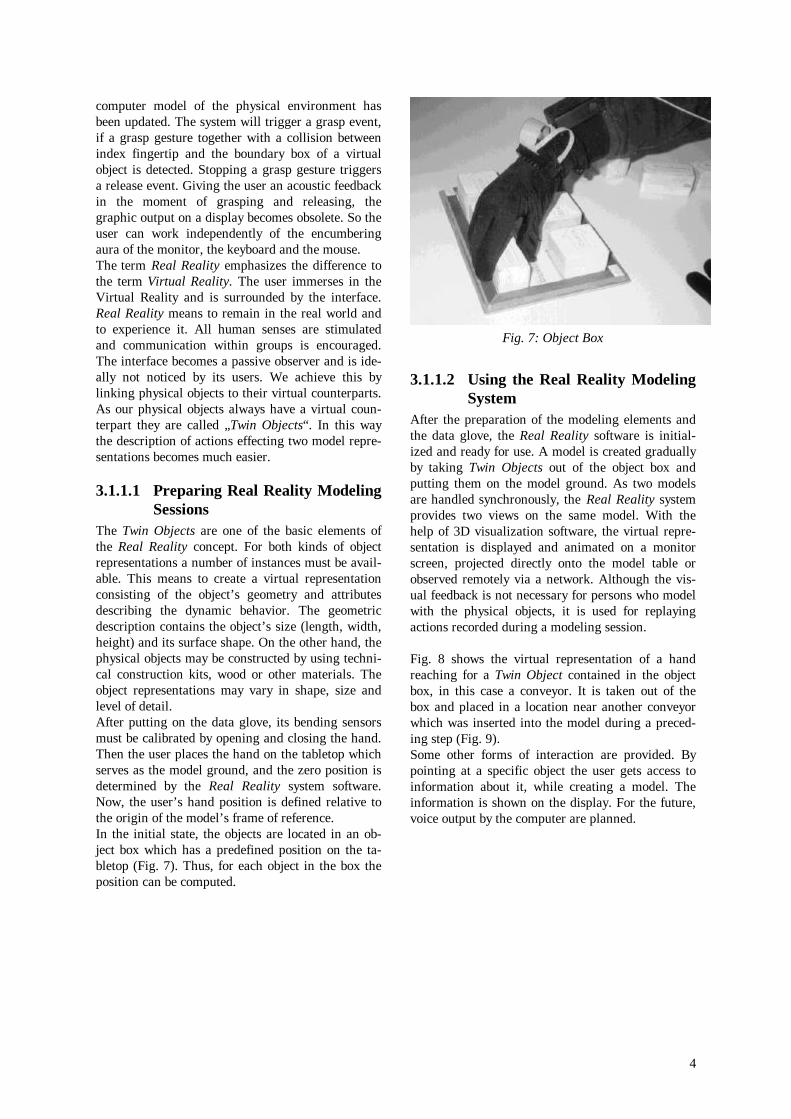
The Twin Objects are one of the basic elements ofthe Real Reality concept. For both kinds of objectrepresentations a number of instances must be avail-able. This means to create a virtual representationconsisting of the object’s geometry and attributesdescribing the dynamic behavior. The geometricdescription contains the object’s size (length, width,height) and its surface shape. On the other hand, thephysical objects may be constructed by using techni-cal construction kits, wood or other materials. Theobject representations may vary in shape, size andlevel of detail.After putting on the data glove, its bending sensorsmust be calibrated by opening and closing the hand.Then the user places the hand on the tabletop whichserves as the model ground, and the zero position isdetermined by the Real Reality system software.Now, the user’s hand position is defined relative tothe origin of the model’s frame of reference.In the initial state, the objects are located in an ob-ject box which has a predefined position on the ta-bletop (Fig. 7). Thus, for each object in the box theposition can be computed.
Fig. 7: Object Box
3.1.1.2 Using the Real Reality ModelingSystem
After the preparation of the modeling elements andthe data glove, the Real Reality software is initial-ized and ready for use. A model is created graduallyby taking Twin Objects out of the object box andputting them on the model ground. As two modelsare handled synchronously, the Real Reality systemprovides two views on the same model. With thehelp of 3D visualization software, the virtual repre-sentation is displayed and animated on a monitorscreen, projected directly onto the model table orobserved remotely via a network. Although the vis-ual feedback is not necessary for persons who modelwith the physical objects, it is used for replayingactions recorded during a modeling session.
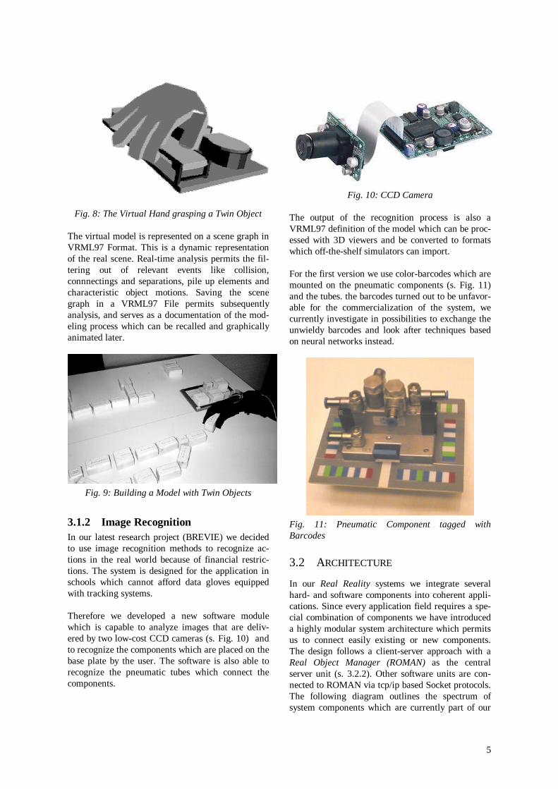
Fig. 8 shows the virtual representation of a handreaching for a Twin Object contained in the objectbox, in this case a conveyor. It is taken out of thebox and placed in a location near another conveyorwhich was inserted into the model during a preced-ing step (Fig. 9).Some other forms of interaction are provided. Bypointing at a specific object the user gets access toinformation about it, while creating a model. Theinformation is shown on the display. For the future,voice output by the computer are planned.
5
Fig. 8: The Virtual Hand grasping a Twin Object
The virtual model is represented on a scene graph inVRML97 Format. This is a dynamic representationof the real scene. Real-time analysis permits the fil-tering out of relevant events like collision,connnectings and separations, pile up elements andcharacteristic object motions. Saving the scenegraph in a VRML97 File permits subsequentlyanalysis, and serves as a documentation of the mod-eling process which can be recalled and graphicallyanimated later.
Fig. 9: Building a Model with Twin Objects
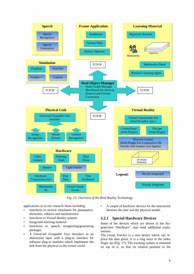
3.1.2 Image RecognitionIn our latest research project (BREVIE) we decidedto use image recognition methods to recognize ac-tions in the real world because of financial restric-tions. The system is designed for the application inschools which cannot afford data gloves equippedwith tracking systems.
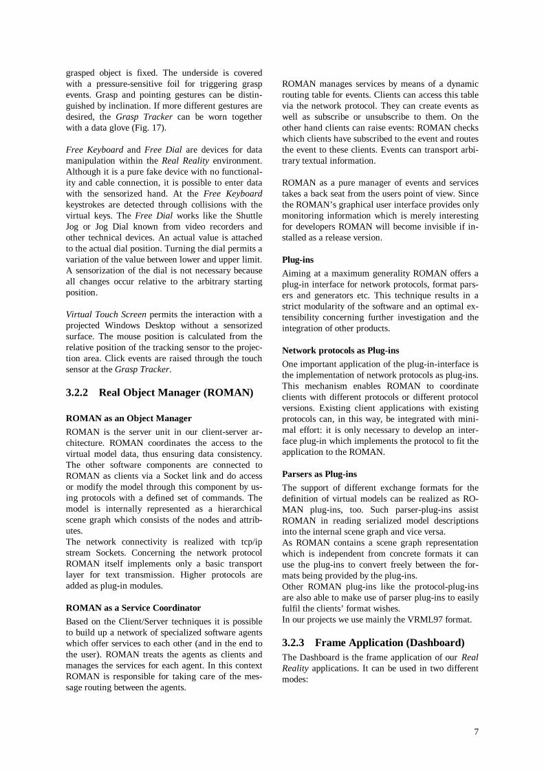
Therefore we developed a new software modulewhich is capable to analyze images that are deliv-ered by two low-cost CCD cameras (s. Fig. 10) andto recognize the components which are placed on thebase plate by the user. The software is also able torecognize the pneumatic tubes which connect thecomponents.
Fig. 10: CCD Camera
The output of the recognition process is also aVRML97 definition of the model which can be proc-essed with 3D viewers and be converted to formatswhich off-the-shelf simulators can import.
For the first version we use color-barcodes which aremounted on the pneumatic components (s. Fig. 11)and the tubes. the barcodes turned out to be unfavor-able for the commercialization of the system, wecurrently investigate in possibilities to exchange theunwieldy barcodes and look after techniques basedon neural networks instead.
Fig. 11: Pneumatic Component tagged withBarcodes
3.2 ARCHITECTURE
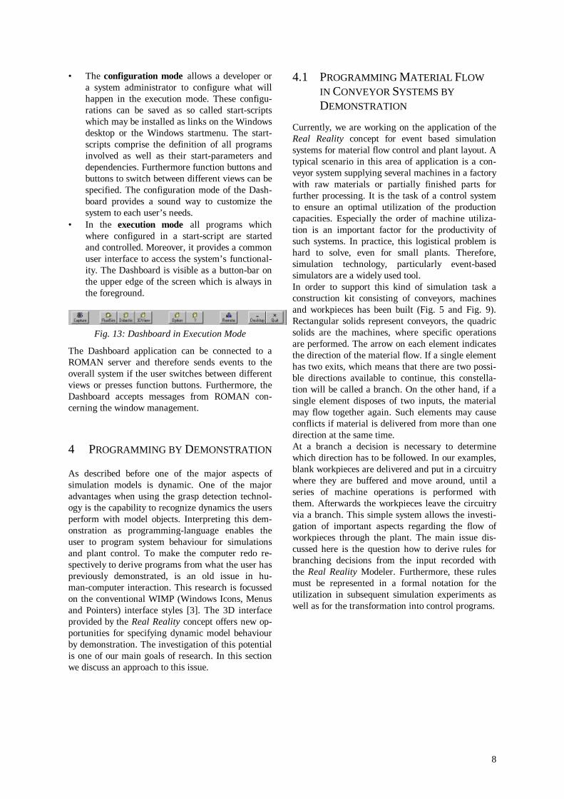
In our Real Reality systems we integrate severalhard- and software components into coherent appli-cations. Since every application field requires a spe-cial combination of components we have introduceda highly modular system architecture which permitsus to connect easily existing or new components.The design follows a client-server approach with aReal Object Manager (ROMAN) as the centralserver unit (s. 3.2.2). Other software units are con-nected to ROMAN via tcp/ip based Socket protocols.The following diagram outlines the spectrum ofsystem components which are currently part of our
6
applications or in our research focus including• Interfaces to several simulators for pneumatics,
electronic, robotics and mechatronics• Interfaces to Virtual Reality systems• Integrated learning material• Interfaces to speech recognizing/generating
packages• A Universal Graspable User Interface as an
abstraction layer with a plug-in interface forsoftware plug-in modules which implement thelink from the physical to the virtual world
• A couple of hardware devices for the interactionbetween the user and the physical model.
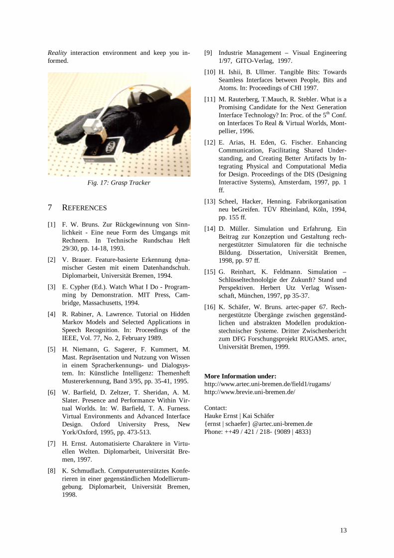
3.2.1 Special Hardware DevicesSome of the devices which are shown in the dia-gram-box “Hardware” may need additional expla-nations:The Grasp Tracker is a new device which can re-place the data glove. It is a ring worn at the indexfinger tip (Fig. 17). The tracking system is mountedon top of it, so that its relative position to the
Real Object Manager- Scene Graph Manager- Blackboard for Services- Protocol and Format
Conversion
Frame Application
Dashboard
System Help
Hotkey Observer
Learning Material
Hypertext Browser
Multimedia Player
Personal Learning Agent
Hypertext
Simulation
TCP/IP
TCP/IP
TCP/IP
TCP/IP
FluidSim PneuSim
Simple++ Cosimir
Virtual Reality
Virtual Construction Kit(WorldToolKit App.)
CosmoPlayer(Web-PlugIn)
Viscape(Web-PlugIn)
Blaxxun Contact(Web-PlugIn For Cooperative VR-Worlds with Avatars and Agents)
)
Physical Link
Universal Graspable UserInterface
ImageRecognition
SensorDrivers
Speech
SpeechRecognition
SpeechGeneration
Hardware
PointingStick
DataGlove
VideoCamera
GestureRecognition
Multimedia-PC
Light PointerBeamer
3D ModelDatabase
HardwareConstruction Kit
Legend: Not yet integrated
Already integrated
Multimedia
FreeKeyboard
FreeDial
Virtual TouchScreen
Fig. 12: Overview of the Real Reality Technology
7
grasped object is fixed. The underside is coveredwith a pressure-sensitive foil for triggering graspevents. Grasp and pointing gestures can be distin-guished by inclination. If more different gestures aredesired, the Grasp Tracker can be worn togetherwith a data glove (Fig. 17).
Free Keyboard and Free Dial are devices for datamanipulation within the Real Reality environment.Although it is a pure fake device with no functional-ity and cable connection, it is possible to enter datawith the sensorized hand. At the Free Keyboardkeystrokes are detected through collisions with thevirtual keys. The Free Dial works like the ShuttleJog or Jog Dial known from video recorders andother technical devices. An actual value is attachedto the actual dial position. Turning the dial permits avariation of the value between lower and upper limit.A sensorization of the dial is not necessary becauseall changes occur relative to the arbitrary startingposition.
Virtual Touch Screen permits the interaction with aprojected Windows Desktop without a sensorizedsurface. The mouse position is calculated from therelative position of the tracking sensor to the projec-tion area. Click events are raised through the touchsensor at the Grasp Tracker.
3.2.2 Real Object Manager (ROMAN)
ROMAN as an Object ManagerROMAN is the server unit in our client-server ar-chitecture. ROMAN coordinates the access to thevirtual model data, thus ensuring data consistency.The other software components are connected toROMAN as clients via a Socket link and do accessor modify the model through this component by us-ing protocols with a defined set of commands. Themodel is internally represented as a hierarchicalscene graph which consists of the nodes and attrib-utes.The network connectivity is realized with tcp/ipstream Sockets. Concerning the network protocolROMAN itself implements only a basic transportlayer for text transmission. Higher protocols areadded as plug-in modules.
ROMAN as a Service CoordinatorBased on the Client/Server techniques it is possibleto build up a network of specialized software agentswhich offer services to each other (and in the end tothe user). ROMAN treats the agents as clients andmanages the services for each agent. In this contextROMAN is responsible for taking care of the mes-sage routing between the agents.
ROMAN manages services by means of a dynamicrouting table for events. Clients can access this tablevia the network protocol. They can create events aswell as subscribe or unsubscribe to them. On theother hand clients can raise events: ROMAN checkswhich clients have subscribed to the event and routesthe event to these clients. Events can transport arbi-trary textual information.
ROMAN as a pure manager of events and servicestakes a back seat from the users point of view. Sincethe ROMAN’s graphical user interface provides onlymonitoring information which is merely interestingfor developers ROMAN will become invisible if in-stalled as a release version.
Plug-insAiming at a maximum generality ROMAN offers aplug-in interface for network protocols, format pars-ers and generators etc. This technique results in astrict modularity of the software and an optimal ex-tensibility concerning further investigation and theintegration of other products.
Network protocols as Plug-insOne important application of the plug-in-interface isthe implementation of network protocols as plug-ins.This mechanism enables ROMAN to coordinateclients with different protocols or different protocolversions. Existing client applications with existingprotocols can, in this way, be integrated with mini-mal effort: it is only necessary to develop an inter-face plug-in which implements the protocol to fit theapplication to the ROMAN.
Parsers as Plug-insThe support of different exchange formats for thedefinition of virtual models can be realized as RO-MAN plug-ins, too. Such parser-plug-ins assistROMAN in reading serialized model descriptionsinto the internal scene graph and vice versa.As ROMAN contains a scene graph representationwhich is independent from concrete formats it canuse the plug-ins to convert freely between the for-mats being provided by the plug-ins.Other ROMAN plug-ins like the protocol-plug-insare also able to make use of parser plug-ins to easilyfulfil the clients’ format wishes.In our projects we use mainly the VRML97 format.
3.2.3 Frame Application (Dashboard)The Dashboard is the frame application of our RealReality applications. It can be used in two differentmodes:
8
• The configuration mode allows a developer ora system administrator to configure what willhappen in the execution mode. These configu-rations can be saved as so called start-scriptswhich may be installed as links on the Windowsdesktop or the Windows startmenu. The start-scripts comprise the definition of all programsinvolved as well as their start-parameters anddependencies. Furthermore function buttons andbuttons to switch between different views can bespecified. The configuration mode of the Dash-board provides a sound way to customize thesystem to each user’s needs.
• In the execution mode all programs whichwhere configured in a start-script are startedand controlled. Moreover, it provides a commonuser interface to access the system’s functional-ity. The Dashboard is visible as a button-bar onthe upper edge of the screen which is always inthe foreground.
Fig. 13: Dashboard in Execution Mode
The Dashboard application can be connected to aROMAN server and therefore sends events to theoverall system if the user switches between differentviews or presses function buttons. Furthermore, theDashboard accepts messages from ROMAN con-cerning the window management.
4 PROGRAMMING BY DEMONSTRATION
As described before one of the major aspects ofsimulation models is dynamic. One of the majoradvantages when using the grasp detection technol-ogy is the capability to recognize dynamics the usersperform with model objects. Interpreting this dem-onstration as programming-language enables theuser to program system behaviour for simulationsand plant control. To make the computer redo re-spectively to derive programs from what the user haspreviously demonstrated, is an old issue in hu-man-computer interaction. This research is focussedon the conventional WIMP (Windows Icons, Menusand Pointers) interface styles [3]. The 3D interfaceprovided by the Real Reality concept offers new op-portunities for specifying dynamic model behaviourby demonstration. The investigation of this potentialis one of our main goals of research. In this sectionwe discuss an approach to this issue.
4.1 PROGRAMMING MATERIAL FLOWIN CONVEYOR SYSTEMS BYDEMONSTRATION
Currently, we are working on the application of theReal Reality concept for event based simulationsystems for material flow control and plant layout. Atypical scenario in this area of application is a con-veyor system supplying several machines in a factorywith raw materials or partially finished parts forfurther processing. It is the task of a control systemto ensure an optimal utilization of the productioncapacities. Especially the order of machine utiliza-tion is an important factor for the productivity ofsuch systems. In practice, this logistical problem ishard to solve, even for small plants. Therefore,simulation technology, particularly event-basedsimulators are a widely used tool.In order to support this kind of simulation task aconstruction kit consisting of conveyors, machinesand workpieces has been built (Fig. 5 and Fig. 9).Rectangular solids represent conveyors, the quadricsolids are the machines, where specific operationsare performed. The arrow on each element indicatesthe direction of the material flow. If a single elementhas two exits, which means that there are two possi-ble directions available to continue, this constella-tion will be called a branch. On the other hand, if asingle element disposes of two inputs, the materialmay flow together again. Such elements may causeconflicts if material is delivered from more than onedirection at the same time.At a branch a decision is necessary to determinewhich direction has to be followed. In our examples,blank workpieces are delivered and put in a circuitrywhere they are buffered and move around, until aseries of machine operations is performed withthem. Afterwards the workpieces leave the circuitryvia a branch. This simple system allows the investi-gation of important aspects regarding the flow ofworkpieces through the plant. The main issue dis-cussed here is the question how to derive rules forbranching decisions from the input recorded withthe Real Reality Modeler. Furthermore, these rulesmust be represented in a formal notation for theutilization in subsequent simulation experiments aswell as for the transformation into control programs.
9
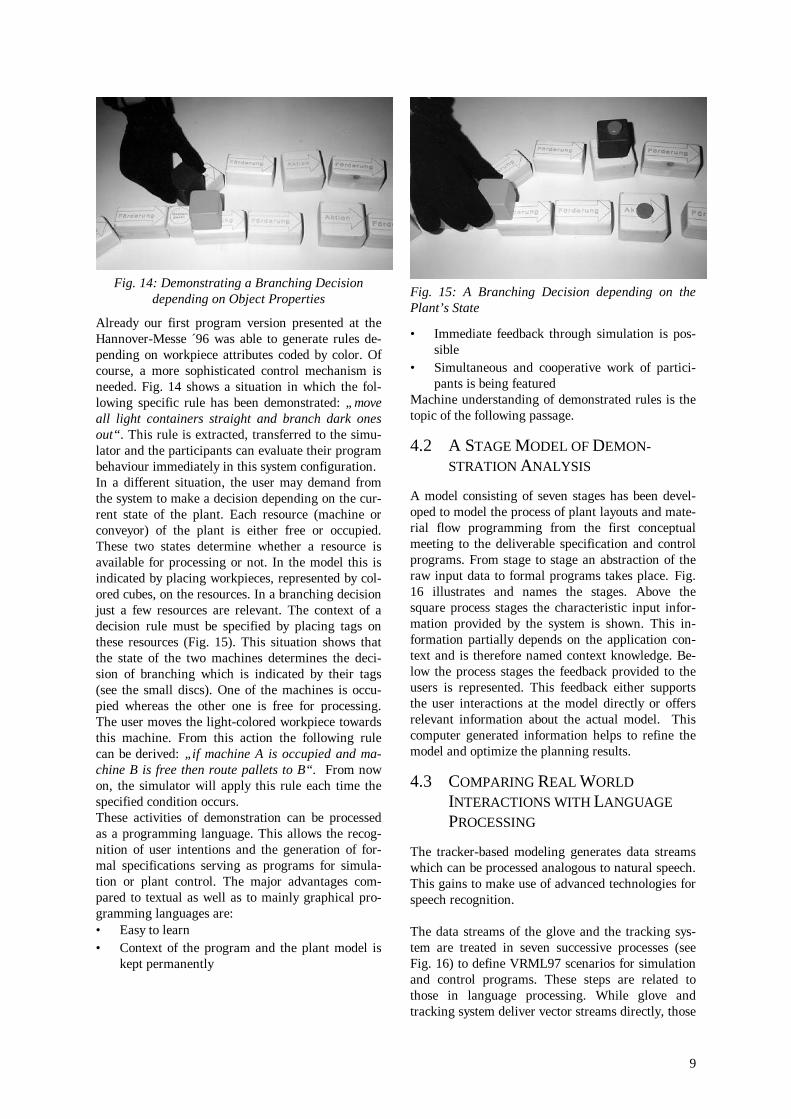
Fig. 14: Demonstrating a Branching Decisiondepending on Object Properties
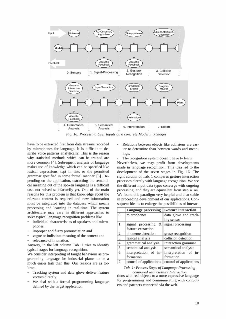
Already our first program version presented at theHannover-Messe ´96 was able to generate rules de-pending on workpiece attributes coded by color. Ofcourse, a more sophisticated control mechanism isneeded. Fig. 14 shows a situation in which the fol-lowing specific rule has been demonstrated: „moveall light containers straight and branch dark onesout“. This rule is extracted, transferred to the simu-lator and the participants can evaluate their programbehaviour immediately in this system configuration.In a different situation, the user may demand fromthe system to make a decision depending on the cur-rent state of the plant. Each resource (machine orconveyor) of the plant is either free or occupied.These two states determine whether a resource isavailable for processing or not. In the model this isindicated by placing workpieces, represented by col-ored cubes, on the resources. In a branching decisionjust a few resources are relevant. The context of adecision rule must be specified by placing tags onthese resources (Fig. 15). This situation shows thatthe state of the two machines determines the deci-sion of branching which is indicated by their tags(see the small discs). One of the machines is occu-pied whereas the other one is free for processing.The user moves the light-colored workpiece towardsthis machine. From this action the following rulecan be derived: „if machine A is occupied and ma-chine B is free then route pallets to B“. From nowon, the simulator will apply this rule each time thespecified condition occurs.These activities of demonstration can be processedas a programming language. This allows the recog-nition of user intentions and the generation of for-mal specifications serving as programs for simula-tion or plant control. The major advantages com-pared to textual as well as to mainly graphical pro-gramming languages are:• Easy to learn• Context of the program and the plant model is
kept permanently
Fig. 15: A Branching Decision depending on thePlant’s State
• Immediate feedback through simulation is pos-sible
• Simultaneous and cooperative work of partici-pants is being featured
Machine understanding of demonstrated rules is thetopic of the following passage.
4.2 A STAGE MODEL OF DEMON-STRATION ANALYSIS
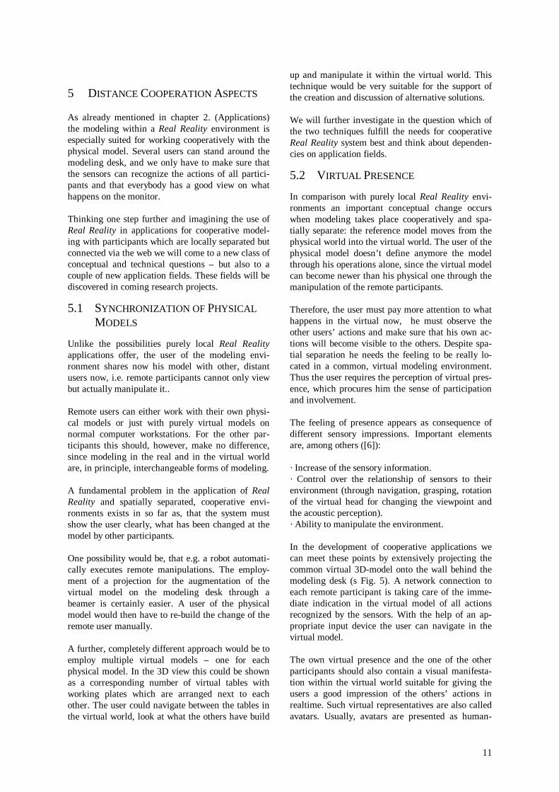
A model consisting of seven stages has been devel-oped to model the process of plant layouts and mate-rial flow programming from the first conceptualmeeting to the deliverable specification and controlprograms. From stage to stage an abstraction of theraw input data to formal programs takes place. Fig.16 illustrates and names the stages. Above thesquare process stages the characteristic input infor-mation provided by the system is shown. This in-formation partially depends on the application con-text and is therefore named context knowledge. Be-low the process stages the feedback provided to theusers is represented. This feedback either supportsthe user interactions at the model directly or offersrelevant information about the actual model. Thiscomputer generated information helps to refine themodel and optimize the planning results.
4.3 COMPARING REAL WORLDINTERACTIONS WITH LANGUAGEPROCESSING
The tracker-based modeling generates data streamswhich can be processed analogous to natural speech.This gains to make use of advanced technologies forspeech recognition.
The data streams of the glove and the tracking sys-tem are treated in seven successive processes (seeFig. 16) to define VRML97 scenarios for simulationand control programs. These steps are related tothose in language processing. While glove andtracking system deliver vector streams directly, those
10
have to be extracted first from data streams recordedby microphones for language. It is difficult to de-scribe voice patterns analytically. This is the reasonwhy statistical methods which can be trained aremore common [4]. Subsequent analysis of languagemakes use of knowledge which can be specified likelexical expressions kept in lists or the permittedgrammar specified in some formal manner [5]. De-pending on the application, extracting the semanti-cal meaning out of the spoken language is a difficulttask not solved satisfactorily yet. One of the mainreasons for this problem is that knowledge about therelevant context is required and new informationmust be integrated into the database which meansprocessing and learning in real-time. The systemarchitecture may vary in different approaches tosolve typical language recognition problems like• individual characteristics of speakers and micro-
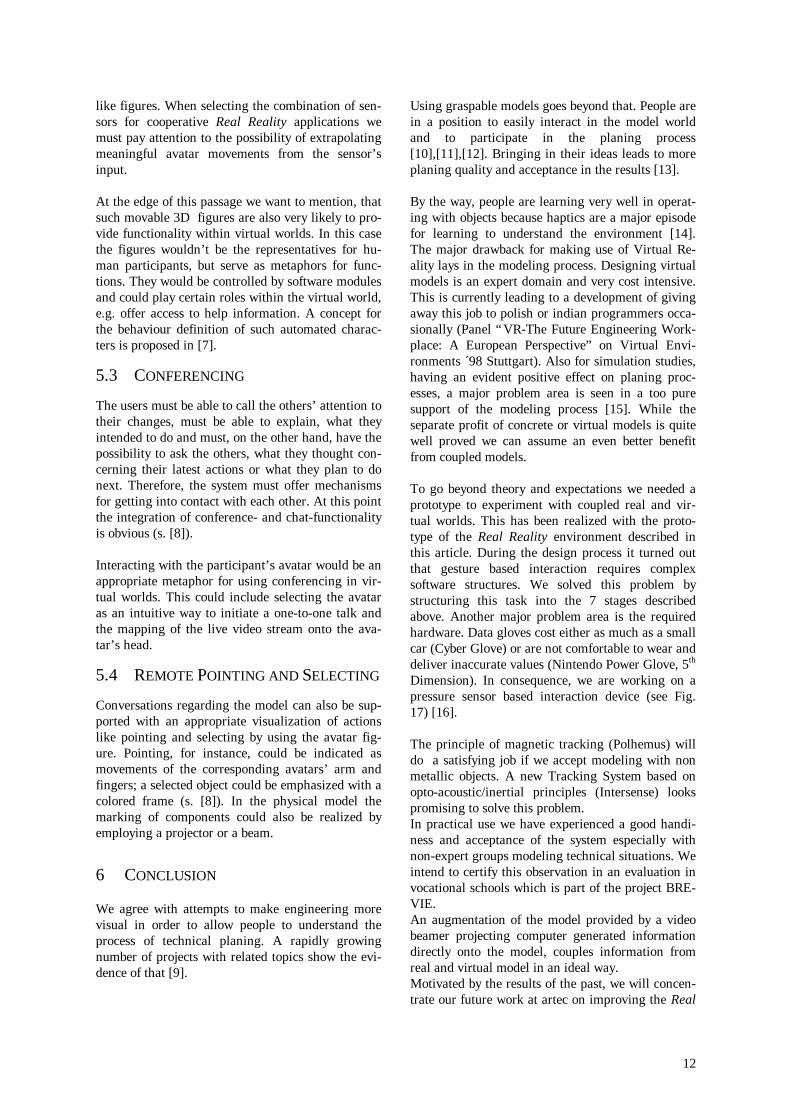
phones,• improper and fuzzy pronunciation and• vague or indistinct meaning of the context and• relevance of intonation.Anyway, in the left column Tab. 1 tries to identifytypical stages for language recognition.We consider interpreting of taught behaviour as pro-gramming language for industrial plants to be amuch easier task than this. Our reasons are as fol-lows:• Tracking system and data glove deliver feature
vectors directly.• We deal with a formal programming language
defined by the target application.
• Relations between objects like collisions are eas-ier to determine than between words and mean-ings.
• The recognition system doesn’t have to learn.Nevertheless, we may profit from developmentsmade in language recognition. This idea led to thedevelopment of the seven stages in Fig. 16. Theright column of Tab. 1 compares gesture interactionprocesses directly with language recognition. We seethe different input data types converge with ongoingprocessing, and they are equivalent from step 4. on.We found this paradigm very helpful and also stablein proceeding development of our applications. Con-sequent idea is to enlarge the possibilities of interac-
tions with real objects to a more expressive languagefor programming and communicating with comput-ers and partners connected via the web.
0. Sensors
4. Grammatical Analysis
1. Signal-Processing
5. SemanticalAnalysis
2. Gesture-Recognition
6. Interpretation
3. Collision-Detection
7. Export
Universe
Gesture-InteractionGrammar
AD-Converter,Algorithms
Input-Semantics
Grasppatterns
Simulation-Engine
Object-Attributes,Geometry
Program-Macros
Model
AcousticFeedback
AcousticFeedback
AcousticFeedback
Animation
Plant
Input
Feedback
Fig. 16: Processing User Inputs on a concrete Model in 7 Stages
Language processing Gesture interaction0. microphones data glove and track-
ing sensor1. signal processing &
feature extractionsignal processing
2. phoneme detection grasp recognition3. lexical analysis collision detection4. grammatical analysis interaction grammar5. semantical analysis semantical analysis6. interpretation of in-
formationinterpretation of in-formation
7. control of applications control of applicationsTab. 1: Process Steps of Language Processing
compared with Gesture Interaction
11
5 DISTANCE COOPERATION ASPECTS
As already mentioned in chapter 2. (Applications)the modeling within a Real Reality environment isespecially suited for working cooperatively with thephysical model. Several users can stand around themodeling desk, and we only have to make sure thatthe sensors can recognize the actions of all partici-pants and that everybody has a good view on whathappens on the monitor.
Thinking one step further and imagining the use ofReal Reality in applications for cooperative model-ing with participants which are locally separated butconnected via the web we will come to a new class ofconceptual and technical questions – but also to acouple of new application fields. These fields will bediscovered in coming research projects.
5.1 SYNCHRONIZATION OF PHYSICALMODELS
Unlike the possibilities purely local Real Realityapplications offer, the user of the modeling envi-ronment shares now his model with other, distantusers now, i.e. remote participants cannot only viewbut actually manipulate it..
Remote users can either work with their own physi-cal models or just with purely virtual models onnormal computer workstations. For the other par-ticipants this should, however, make no difference,since modeling in the real and in the virtual worldare, in principle, interchangeable forms of modeling.
A fundamental problem in the application of RealReality and spatially separated, cooperative envi-ronments exists in so far as, that the system mustshow the user clearly, what has been changed at themodel by other participants.
One possibility would be, that e.g. a robot automati-cally executes remote manipulations. The employ-ment of a projection for the augmentation of thevirtual model on the modeling desk through abeamer is certainly easier. A user of the physicalmodel would then have to re-build the change of theremote user manually.
A further, completely different approach would be toemploy multiple virtual models – one for eachphysical model. In the 3D view this could be shownas a corresponding number of virtual tables withworking plates which are arranged next to eachother. The user could navigate between the tables inthe virtual world, look at what the others have build
up and manipulate it within the virtual world. Thistechnique would be very suitable for the support ofthe creation and discussion of alternative solutions.
We will further investigate in the question which ofthe two techniques fulfill the needs for cooperativeReal Reality system best and think about dependen-cies on application fields.
5.2 VIRTUAL PRESENCE
In comparison with purely local Real Reality envi-ronments an important conceptual change occurswhen modeling takes place cooperatively and spa-tially separate: the reference model moves from thephysical world into the virtual world. The user of thephysical model doesn’t define anymore the modelthrough his operations alone, since the virtual modelcan become newer than his physical one through themanipulation of the remote participants.
Therefore, the user must pay more attention to whathappens in the virtual now, he must observe theother users’ actions and make sure that his own ac-tions will become visible to the others. Despite spa-tial separation he needs the feeling to be really lo-cated in a common, virtual modeling environment.Thus the user requires the perception of virtual pres-ence, which procures him the sense of participationand involvement.
The feeling of presence appears as consequence ofdifferent sensory impressions. Important elementsare, among others ([6]):
· Increase of the sensory information.· Control over the relationship of sensors to theirenvironment (through navigation, grasping, rotationof the virtual head for changing the viewpoint andthe acoustic perception).· Ability to manipulate the environment.
In the development of cooperative applications wecan meet these points by extensively projecting thecommon virtual 3D-model onto the wall behind themodeling desk (s Fig. 5). A network connection toeach remote participant is taking care of the imme-diate indication in the virtual model of all actionsrecognized by the sensors. With the help of an ap-propriate input device the user can navigate in thevirtual model.
The own virtual presence and the one of the otherparticipants should also contain a visual manifesta-tion within the virtual world suitable for giving theusers a good impression of the others’ actions inrealtime. Such virtual representatives are also calledavatars. Usually, avatars are presented as human-
12
like figures. When selecting the combination of sen-sors for cooperative Real Reality applications wemust pay attention to the possibility of extrapolatingmeaningful avatar movements from the sensor’sinput.
At the edge of this passage we want to mention, thatsuch movable 3D figures are also very likely to pro-vide functionality within virtual worlds. In this casethe figures wouldn’t be the representatives for hu-man participants, but serve as metaphors for func-tions. They would be controlled by software modulesand could play certain roles within the virtual world,e.g. offer access to help information. A concept forthe behaviour definition of such automated charac-ters is proposed in [7].
5.3 CONFERENCING
The users must be able to call the others’ attention totheir changes, must be able to explain, what theyintended to do and must, on the other hand, have thepossibility to ask the others, what they thought con-cerning their latest actions or what they plan to donext. Therefore, the system must offer mechanismsfor getting into contact with each other. At this pointthe integration of conference- and chat-functionalityis obvious (s. [8]).
Interacting with the participant’s avatar would be anappropriate metaphor for using conferencing in vir-tual worlds. This could include selecting the avataras an intuitive way to initiate a one-to-one talk andthe mapping of the live video stream onto the ava-tar’s head.
5.4 REMOTE POINTING AND SELECTING
Conversations regarding the model can also be sup-ported with an appropriate visualization of actionslike pointing and selecting by using the avatar fig-ure. Pointing, for instance, could be indicated asmovements of the corresponding avatars’ arm andfingers; a selected object could be emphasized with acolored frame (s. [8]). In the physical model themarking of components could also be realized byemploying a projector or a beam.
6 CONCLUSION
We agree with attempts to make engineering morevisual in order to allow people to understand theprocess of technical planing. A rapidly growingnumber of projects with related topics show the evi-dence of that [9].
Using graspable models goes beyond that. People arein a position to easily interact in the model worldand to participate in the planing process[10],[11],[12]. Bringing in their ideas leads to moreplaning quality and acceptance in the results [13].
By the way, people are learning very well in operat-ing with objects because haptics are a major episodefor learning to understand the environment [14].The major drawback for making use of Virtual Re-ality lays in the modeling process. Designing virtualmodels is an expert domain and very cost intensive.This is currently leading to a development of givingaway this job to polish or indian programmers occa-sionally (Panel “VR-The Future Engineering Work-place: A European Perspective” on Virtual Envi-ronments ´98 Stuttgart). Also for simulation studies,having an evident positive effect on planing proc-esses, a major problem area is seen in a too puresupport of the modeling process [15]. While theseparate profit of concrete or virtual models is quitewell proved we can assume an even better benefitfrom coupled models.
To go beyond theory and expectations we needed aprototype to experiment with coupled real and vir-tual worlds. This has been realized with the proto-type of the Real Reality environment described inthis article. During the design process it turned outthat gesture based interaction requires complexsoftware structures. We solved this problem bystructuring this task into the 7 stages describedabove. Another major problem area is the requiredhardware. Data gloves cost either as much as a smallcar (Cyber Glove) or are not comfortable to wear anddeliver inaccurate values (Nintendo Power Glove, 5th
Dimension). In consequence, we are working on apressure sensor based interaction device (see Fig.17) [16].
The principle of magnetic tracking (Polhemus) willdo a satisfying job if we accept modeling with nonmetallic objects. A new Tracking System based onopto-acoustic/inertial principles (Intersense) lookspromising to solve this problem.In practical use we have experienced a good handi-ness and acceptance of the system especially withnon-expert groups modeling technical situations. Weintend to certify this observation in an evaluation invocational schools which is part of the project BRE-VIE.An augmentation of the model provided by a videobeamer projecting computer generated informationdirectly onto the model, couples information fromreal and virtual model in an ideal way.Motivated by the results of the past, we will concen-trate our future work at artec on improving the Real
13
Reality interaction environment and keep you in-formed.
Fig. 17: Grasp Tracker
7 REFERENCES
[1] F. W. Bruns. Zur Rückgewinnung von Sinn-lichkeit - Eine neue Form des Umgangs mitRechnern. In Technische Rundschau Heft29/30, pp. 14-18, 1993.
[2] V. Brauer. Feature-basierte Erkennung dyna-mischer Gesten mit einem Datenhandschuh.Diplomarbeit, Universität Bremen, 1994.
[3] E. Cypher (Ed.). Watch What I Do - Program-ming by Demonstration. MIT Press, Cam-bridge, Massachusetts, 1994.
[4] R. Rabiner, A. Lawrence. Tutorial on HiddenMarkov Models and Selected Applications inSpeech Recognition. In: Proceedings of theIEEE, Vol. 77, No. 2, February 1989.
[5] H. Niemann, G. Sagerer, F. Kummert, M.Mast. Repräsentation und Nutzung von Wissenin einem Spracherkennungs- und Dialogsys-tem. In: Künstliche Intelligenz: ThemenheftMustererkennung, Band 3/95, pp. 35-41, 1995.
[6] W. Barfield, D. Zeltzer, T. Sheridan, A. M.Slater. Presence and Performance Within Vir-tual Worlds. In: W. Barfield, T. A. Furness.Virtual Environments and Advanced InterfaceDesign. Oxford University Press, NewYork/Oxford, 1995, pp. 473-513.
[7] H. Ernst. Automatisierte Charaktere in Virtu-ellen Welten. Diplomarbeit, Universität Bre-men, 1997.
[8] K. Schmudlach. Computerunterstütztes Konfe-rieren in einer gegenständlichen Modellierum-gebung. Diplomarbeit, Universität Bremen,1998.
[9] Industrie Management – Visual Engineering1/97, GITO-Verlag, 1997.
[10] H. Ishii, B. Ullmer. Tangible Bits: TowardsSeamless Interfaces between People, Bits andAtoms. In: Proceedings of CHI 1997.
[11] M. Rauterberg, T.Mauch, R. Stebler. What is aPromising Candidate for the Next GenerationInterface Technology? In: Proc. of the 5th Conf.on Interfaces To Real & Virtual Worlds, Mont-pellier, 1996.
[12] E. Arias, H. Eden, G. Fischer. EnhancingCommunication, Facilitating Shared Under-standing, and Creating Better Artifacts by In-tegrating Physical and Computational Mediafor Design. Proceedings of the DIS (DesigningInteractive Systems), Amsterdam, 1997, pp. 1ff.
[13] Scheel, Hacker, Henning. Fabrikorganisationneu beGreifen. TÜV Rheinland, Köln, 1994,pp. 155 ff.
[14] D. Müller. Simulation und Erfahrung. EinBeitrag zur Konzeption und Gestaltung rech-nergestützter Simulatoren für die technischeBildung. Dissertation, Universität Bremen,1998, pp. 97 ff.
[15] G. Reinhart, K. Feldmann. Simulation –Schlüsseltechnololgie der Zukunft? Stand undPerspektiven. Herbert Utz Verlag Wissen-schaft, München, 1997, pp 35-37.
[16] K. Schäfer, W. Bruns. artec-paper 67. Rech-nergestützte Übergänge zwischen gegenständ-lichen und abstrakten Modellen produktion-stechnischer Systeme. Dritter Zwischenberichtzum DFG Forschungsprojekt RUGAMS. artec,Universität Bremen, 1999.
More Information under:http://www.artec.uni-bremen.de/field1/rugams/http://www.brevie.uni-bremen.de/
Contact:Hauke Ernst | Kai Schäfer{ernst | schaefer} @artec.uni-bremen.dePhone: ++49 / 421 / 218- {9089 | 4833}