Embed Size (px)
Citation preview
Dane Kouttron 12/4/06LITEC Preliminary enhancement overview
Creating a Wireless serial Terminal(For less than $20)
- 1 -

Dane Kouttron 12/4/06LITEC Preliminary enhancement overview
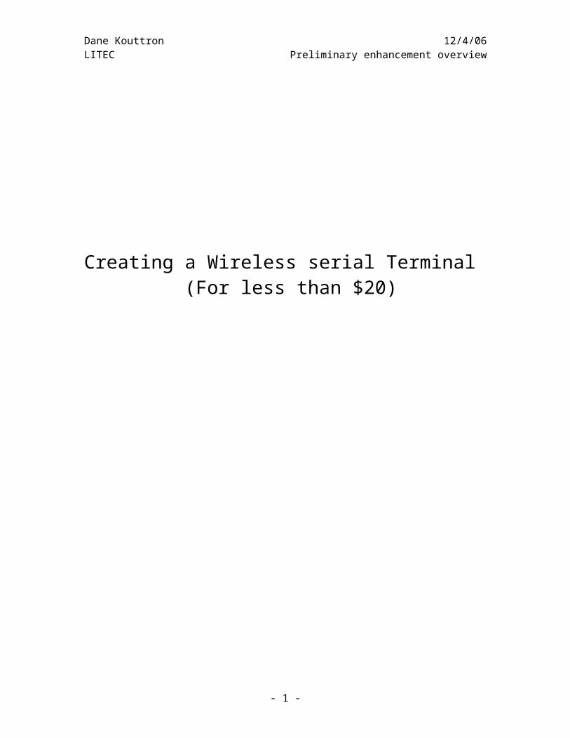
As shown, this is the initial beginning of the project. We can see here a bread board, a lcd wired to the board, labeled pins, and a huge capacitor in the mains line. This is to prevent any fluctuations in the actual power supply. The MAX 232 is a level shifter. A level shifter switches the ttl level operations on the atmega 48 to rs232 compliant 10v and 0 volt (inverted Figure 1
- 2 -
Dane Kouttron 12/4/06LITEC Preliminary enhancement overview
Compiling, coding and communicating. This dell laptop is extremely uselful. It has both parallel (5v) and serial communications without the requirement of external usb adapters. Instead of programming with proprietary expensive programmers, I connect the miso, mosi, clock, ground and reset pins according to the programmer schematic
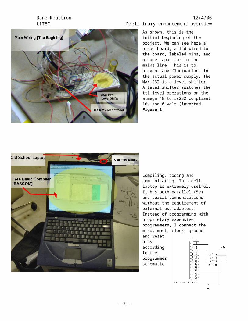
DB25 pin Target MCU pin(AT90S8535)
Target MCUM103/M128
Target MCU pin 8515 DT104
2, D0 MOSI, pin 6 PE.0, 2 MOSI, 6 J5, pin 44, D2 RESET, pin 9 RESET, 20 RESET, 9 J5, pin 85, D3 CLOCK, pin 8 PB.1,11 CLOCK, 8 J5, pin 611, BUSY MISO, pin 7 PE.1, 3 MISO, 7 J5, pin 518-25,GND GROUND GROUND GND,20 J5, pin 1
[connection guide for parallel port programmer]
- 3 -
Dane Kouttron 12/4/06LITEC Preliminary enhancement overviewPinout from spec sheet [Atmel ATMEGA48 Spec Sheet]
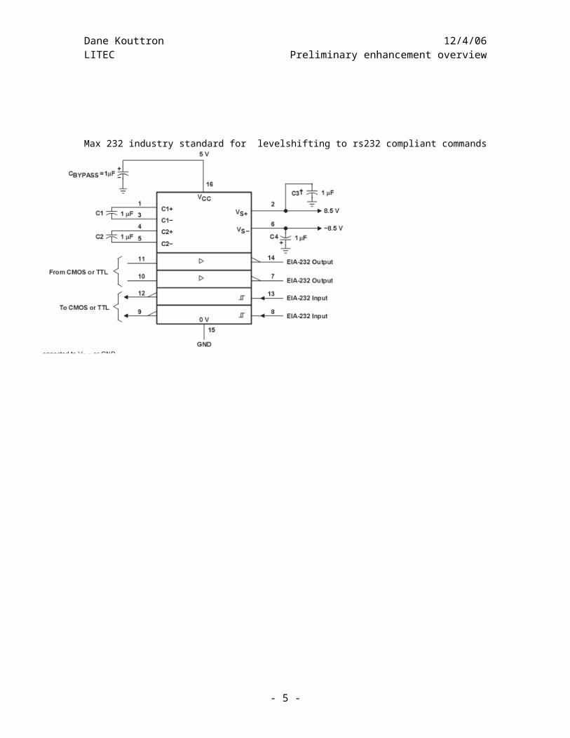
Max 232 industry standard for levelshifting to rs232 compliant commands
- 4 -
Dane Kouttron 12/4/06LITEC Preliminary enhancement overview
Using data from the specifications sheet I was able to power and program the ATMEGA 48 automotive microcontroller using nothing more than a parallel port, 5v power supply and a computer. The software bundle I used is called BASCOM produced by MCS electronics. This slight disparity
On the main breadboard vcc (5V) is linked to both pin 7,21,and 20 and grounds correspond to pin 8 and 22.
For this project I used c1- c5 for display control lines to deliver the hd44780 based 24X2 lcd display I used pin d2 as the enable for the display and use [ see display wiring schematic]
Moreover for the receiver end I used 4 rechargeable batteries [1.2V each] to provide 4.8 v (nearly 5v for the microcontroller)
The RX (pin D.0) was used for incoming serial communications (re-inverted from the MAX 232 serial level shifter)
The incoming serial commands were characterized as a string, as any integer or word definition would severely limit the capability for a long amount of information to be passed through. As none of the information needed to be really stored in the uC, I used a buffer-style code method to generate the proper lcd driving from the incoming serial string.
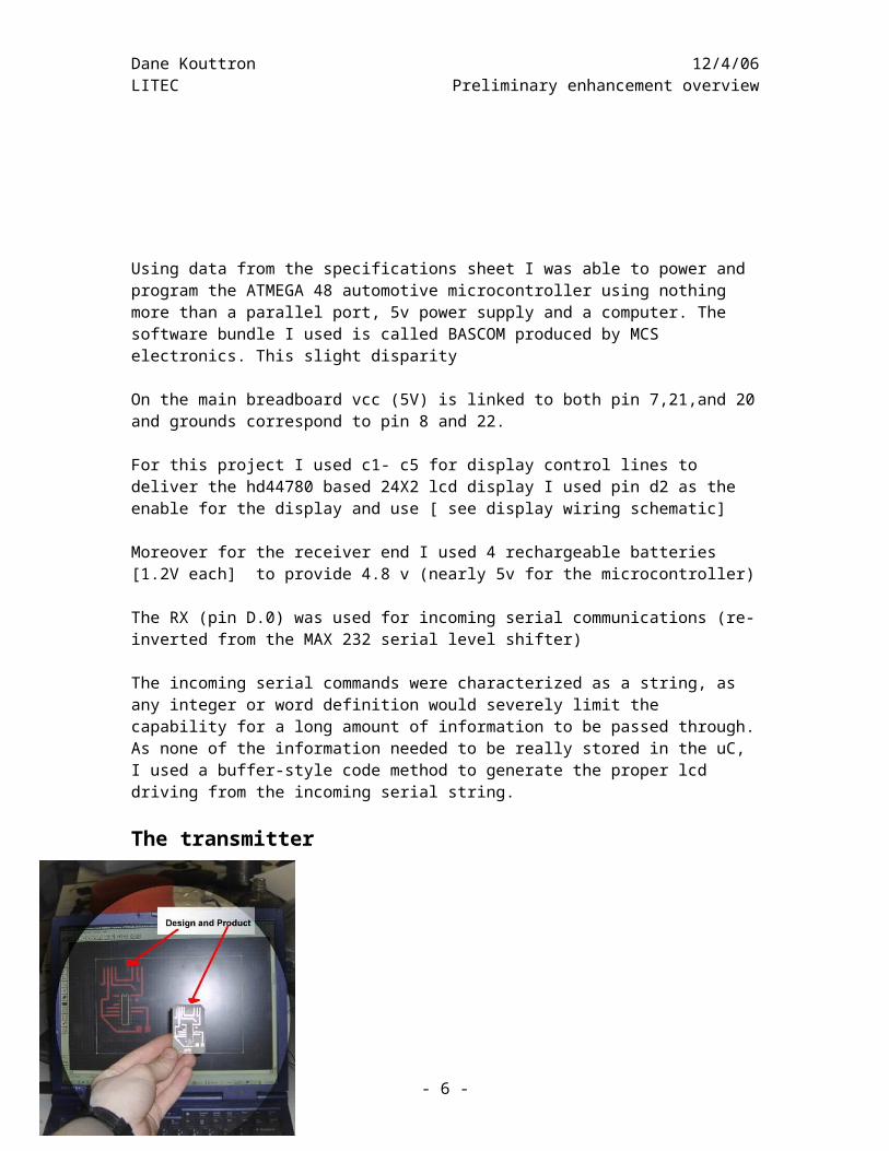
The transmitterInitially I designed the transmitter so that I could simply hide it in the blimp without having to worry about TA’s getting annoyed. To do this I made it run from a separate 9v power supply with a linear 7805 regulator. This provided a stable 5v for my system so that I could drive the max 232 and transmitter. Next I designed the board. Using free software again, I built and designed the pcb (printed circuit board. I inverted the image using ‘the gimp’ yet again, another piece of free software) and used it to furthermore clean up the design.
- 5 -
Dane Kouttron 12/4/06LITEC Preliminary enhancement overview
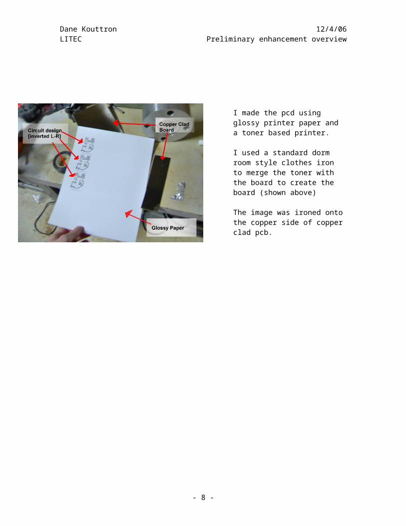
I made the pcd using glossy printer paper and a toner based printer.
I used a standard dorm room style clothes iron to merge the toner with the board to create the board (shown above)
The image was ironed onto the copper side of copper clad pcb.
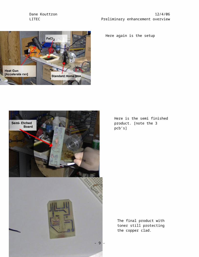
Here again is the setup
Here is the semi finished product. [note the 3 pcb’s]
- 6 -
Dane Kouttron 12/4/06LITEC Preliminary enhancement overview
The final product with toner still protecting the copper clad.
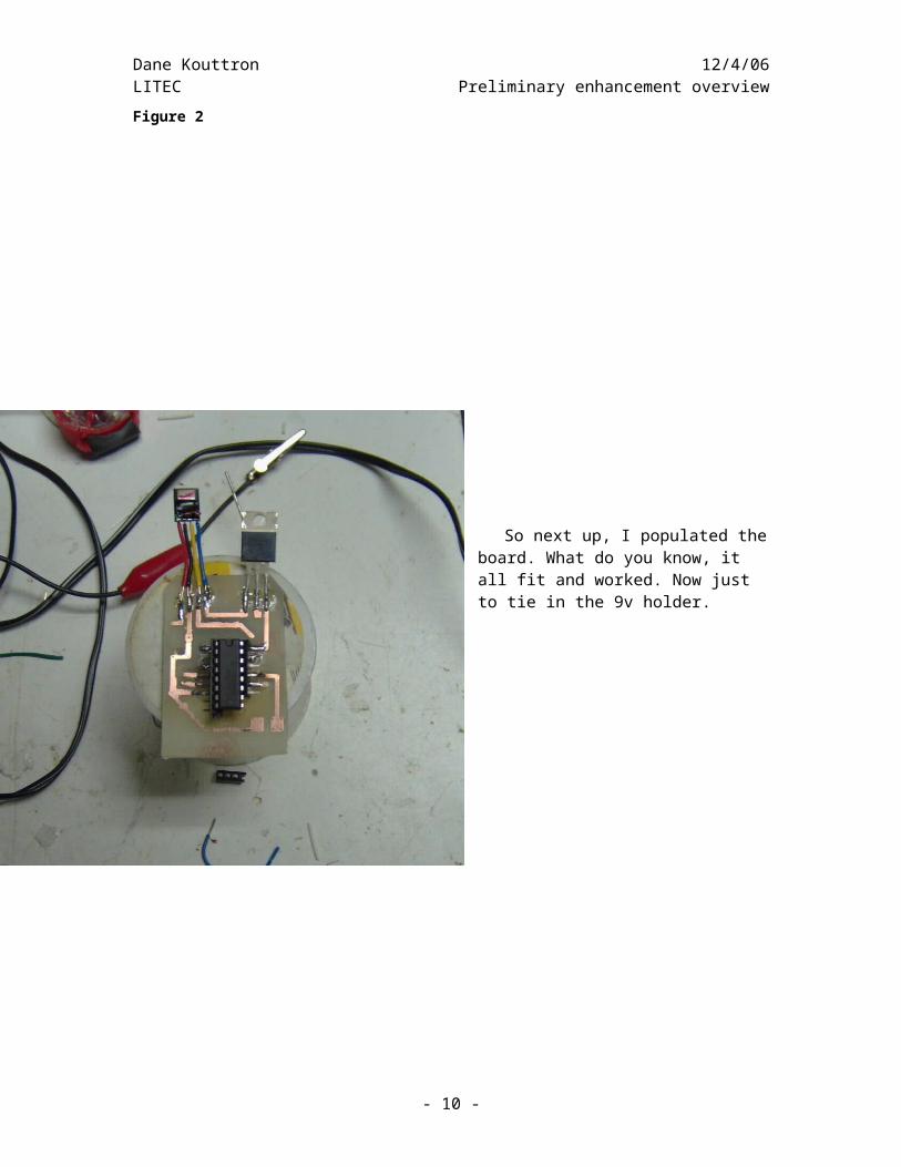
Figure 2
So next up, I populated the board. What do you know, it all fit and worked. Now just to tie in the 9v holder.
- 7 -
Dane Kouttron 12/4/06LITEC Preliminary enhancement overview
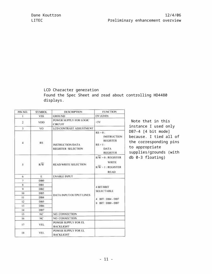
LCD Character generationFound the Spec Sheet and read about controlling HD4480 displays.
Note that in this instance I used only DB7-4 [4 bit mode] because. I tied all of the corresponding pins to appropriate supplies/grounds (with db 0-3 floating)
- 8 -
Dane Kouttron 12/4/06LITEC Preliminary enhancement overview
In lab testing. The serial terminal worked properly across t he litec room and out the door while transmitting text from a text file ‘hackers handbook’ from a serial port.
Unfortunately the litec hardware does not support the baud rate this functions at and the
- 9 -
Dane Kouttron 12/4/06LITEC Preliminary enhancement overview
Cost sheet Supplier priceMega 48 Futurelec 1.90Software MCS Free DemoLCD Allelectronics 4.00Glossy paper VCC FreeMAX 232 Nat.Semi Free (sampled)Transmitter Mouser 4.15Reciever Mouser ~5.00
$15.05
How it was done: The Code
regfile = "m48def.dat" 'This is the chips data file (like a h. file)$baud = ' use baud rate$hwstack = 32 ' chip stack size$swstack = 10 'Chip stack size10$framesize = 40 'chip's frams size
Config Serialin = Buffered , Size = 20
$crystal = 8000000 'functioning frequency of chip
Config Com1 = Dummy , Synchrone = 0 , Parity = None , Stopbits = 1 , Databits = 8 , Clockpol = 0
Config Lcdpin = Pin , Db4 = Portb.4 , Db5 = Portb.5 , Db6 = Portb.6 , Db7 = Portb.7 , E = Portc.7 , Rs = Portc.6
Dim V As String * 24 'i used string * 24 because we have a 24 character LCD
$serialinput2lcd
Lcd "loading OS "Waitms 100ClsLcd "copyright DK LABS"Waitms 500ClsLcd "initializing system "Lowerline "initializing communications "Cls
- 10 -
Dane Kouttron 12/4/06LITEC Preliminary enhancement overview
Do Cls Input "" , V 'this will go to the LCD displayLoop
[And now you have a fully functioning wireless serial terminal at 2400 Baud]
Why did we use a different hardware?
The goal of this enhancement was to use what we have learned throughout this year and impress those who instructed us and to perform a huge goal in short time with no budget. After coming up with the idea, it was implemented over the course of 46 hours, most of which were spent trying to get the hyperterminal to work properly as it performs a strange hardware overflow check even when it is not selected.
What language is this?This language is a form of BASIC. This language is designed to be simple for
prototyping purposes. If you are working in a company and need to make a simple prototype you don’t want to spend weeks tooling out lines of C code, when you can use a huge selection of subroutine like H files which encompass separate actions. Note that ‘serialin” is on one of those subroutines, it takes care of handshake over serial and best approximates the proper clocking. For example, our clock was an internally oscillated 8mhz, based on an LRC timer style oscillator. Yes, this is not as accurate as the 22.1184 mhz external oscillator that the LITEC Smart Car, Gondola, and Blimp use.
What problems did we face?
The main problem, after interfacing properly, getting the LCD to work, getting the Device to work wired, and then wirelessly was trying to get stable communications wirelessly. I determined then that the minimum that it could operate was at the 2400 baud rate. This rate is quite low, but within the operating capability of our hardware. Our main problem was getting HyperTerminal to function properly. After over 2 hours of tinkering, I found that instead of being frustrated, I downloaded a 3rd party hyper terminal program offline for free.
What did we learn?
We learned quite a lot performing this enhancement and spent quite a bit of a weekend designing, constructing, and testing the tool we made. We learned how to drive a hd4480 based Hitachi LCD, how to read specification sheets and how to make things work on a limited timescale.
What I could have done:
Given an appropriate amount of time I could have use 2 microcontrollers, one to input serial coms at the higher speed that the blimp speaks at (9600),
- 11 -
Dane Kouttron 12/4/06LITEC Preliminary enhancement overviewparse small periods of the string, store it in an array, and mathematically translate it to a slower baud rate that the transmitter can handle. I could also hone in on my antenna design.
- 12 -