Embed Size (px)
Citation preview
File E90700 Vol 2 Auth. Page 1 Issued: 1998-11-17 Revised: 2016-03-11
FOLLOW-UP SERVICE PROCEDURE (TYPE R)
COMPONENT - OPTICAL ISOLATORS (FPQU2,FPQU8)
Manufacturer: SEE ADDENDUM FOR MANUFACTURER LOCATIONS
642005 (Party Site) Applicant: FAIRCHILD SEMICONDUCTOR CORP (725625-001) 1272 Borregas Ave Sunnyvale CA 94089
642005 (Party Site) Recognized Company: SAME AS APPLICANT (725625-001)
This Follow-Up Service Procedure authorizes the above Manufacturer(s) to use the marking specified by UL LLC, or any authorized licensee of UL LLC, including the UL Contracting Party, only on products when constructed, tested and found to be in compliance with the requirements of this Follow-Up Service Procedure and in accordance with the terms of the applicable service agreement with UL Contracting Party and any applicable Service Terms. The UL Contracting Party for Follow-Up Services is listed on addendum to this Follow-Up Service Procedure ("UL Contracting Party"). UL Contracting Party and UL LLC are referred to jointly herein as "UL."
UL further defines responsibilities, duties and requirements for both Manufacturers and UL representatives in the document titled, "UL Mark Surveillance Requirements" that can be located at the following web-site: http://www.ul.com/fus and in the document titled "UL and Subscriber Responsibilities" that can be located at the following website: http://www.ul.com/responsibilities. Manufacturers without Internet access may obtain the current version of these documents from their local UL customer service representative or UL field representative. For assistance, or to obtain a paper copy of these documents or the applicable Service Terms, please contact UL's Customer Service at http://ul.com/aboutul/locations/, select a location and enter your request, or call the number listed for that location.
The Applicant, the specified Manufacturer(s) and any Recognized Company in this Follow-Up Service Procedure must agree to receive Follow-Up Services from UL Contracting Party. If your applicable agreement is a Global Services Agreement ("GSA") with an effective date of January 1, 2012 or later and this Follow-Up Service Procedure is issued on or after that effective date, the Applicant, the specified Manufacturer(s) and any Recognized Company will be bound to a Service Agreement for Follow-Up Services upon the earliest by any Subscriber of use of the prescribed UL Mark, acceptance of the factory inspection, or payment of the Follow-Up Service fees which will incorporate such GSA, this Follow-Up Service Procedure and the Follow-Up Service Terms which can be accessed by clicking here: http://www.ul.com/contracts/Terms-After-12-31-2011. In all other events, Follow-Up Services will be governed by and incorporate the terms of your applicable service agreement and this Follow-Up Service Procedure.
Created by UL Document Assembler 2016-09-13 21:50:29 -05:00
File E90700 Vol 2 Auth. Page 2 Issued: 1998-11-17 Revised: 2016-03-11
It is the responsibility of the Recognized Company to make sure that only the products meeting the aforementioned requirements bear the authorized Marks of UL LLC, or any authorized licensee of UL LLC.
This Follow-Up Service Procedure contains information for the use of the above Manufacturer(s) and representatives of UL and is not to be used for any other purpose. It is provided to the Manufacturer with the understanding that it will be returned upon request and is not to be copied in whole or in part.
This Follow-Up Service Procedure, and any subsequent revisions, is the property of UL and is not transferable. This Follow-Up Service Procedure contains confidential information for use only by the above named Manufacturer(s) and representatives of UL and is not to be used for any other purpose. It is provided to the Subscribers with the understanding that it is not to be copied, either wholly or in part unless specifically allowed, and that it will be returned to UL, upon request.
Capitalized terms used but not defined herein have the meanings set forth in the GSA and the applicable Service Terms or any other applicable UL service agreement.
UL shall not incur any obligation or liability for any loss, expense or damages, including incidental, consequential or punitive damages arising out of or in connection with the use or reliance upon this Follow-Up Service Procedure to anyone other than the above Manufacturer(s) as provided in the agreement between UL LLC or an authorized licensee of UL LLC, including UL Contracting Party, and the Manufacturer(s).
UL LLC has signed below solely in its capacity as the accredited entity to indicate that this Follow-Up Service Procedure is in compliance with the accreditation requirements.
Bruce A. MahrenholzDirectorNorth American Certification Program
Created by UL Document Assembler 2016-09-13 21:50:29 -05:00

File E90700 Vol 2 Addendum To Page 1 Issued: 1998-11-17 Authorization Page Revised: 2016-03-11
LOCATION
560790 (Party Site)(153559-001) LITE-ON ELECTRONICS (THAILAND) CO LTD 38/4 MOO 1 RANGSIT-ONGKARAK RD BUNGYEETOH TANYABURI PHATHUMTHANI 12130 THAILANDFactory ID: NoneUL Contracting Party for above site is: UL AG
Created by UL Document Assembler 2016-09-13 21:50:29 -05:00

THIS FORM PAGE IS TO BE REVISED BY THE NORTHBROOK LABEL DEPARTMENT ONLY
Recognized Component Marking Data Page (RCMDP)
(FILE IMMEDIATELY AFTER AUTHORIZATION PAGE)
RECOGNIZED COMPONENT MARKING
Products Recognized under UL’s Component Recognition Service are identified by marking elements consisting of:
1. The Recognized Company’s identification specified in this document.
2. A catalog, model or other applicable product designation specified in the descriptive sections of this document.
3. The UL Recognized Component Mark shown below is optional unlessrequired elsewhere in the Procedure.
Only those components, which actually bear the Marking, should be considered as being covered under the Recognition Program. The UL Listing or Classification Mark is not authorized for use on or in connection with Recognized Components.
Recognized Component Mark
Minimum size of the Recognized Component Mark is not specified as long as it is legible. Minimum height of the registered symbol ® shall be 3/64 inch but may be omitted if it is out of proportion to the Recognized Component Mark or not legible to the naked eye.
The manufacturer may reproduce the Mark electronically. Any decision regarding the acceptability of the manufacturer’s Mark reproduction will be made at the Reviewing Office.
Created by UL Document Assembler 2016-09-13 21:50:29 -05:00

THIS FORM PAGE IS TO BE REVISED BY THE NORTHBROOK LABEL DEPARTMENT ONLY
Recognized Component Marking Data Page (RCMDP)
(FILE IMMEDIATELY AFTER AUTHORIZATION PAGE)
RECOGNIZED COMPONENT MARKING
Products Recognized under UL’s Component Recognition Service are identified by marking elements consisting of:
1. The Recognized Company’s identification specified in this document.
2. A catalog, model or other applicable product designation specified in the descriptive sections of this document.
3. The UL Recognized Component Mark shown below:(A) Recognized only to Canadian safety requirements, or;(B) Recognized to both U.S. and Canadian safety requirements.
Only those components, which actually bear the Marking, should be considered as being covered under the Recognition Program. The UL Listing or Classification Mark is not authorized for use on or in connection with Recognized Components.
Recognized Component Mark
Minimum size of the Recognized Component Mark is not specified as long as it is legible. Minimum height of the registered symbol ® shall be 3/64 inch but may be omitted if it is out of proportion to the Recognized Component Mark or not legible to the naked eye.
The manufacturer may reproduce the Mark electronically. Any decision regarding the acceptability of the manufacturer’s Mark reproduction will be made at the Reviewing Office.
Created by UL Document Assembler 2016-09-13 21:50:29 -05:00

File E90700 Vol. 2 Index Page 1 Issued: 1998-11-17Revised: 2016-05-23
INDEX
Cat. No Section Report DateUSR – Double Protection Optical Isolators, Construction Code “Q”, six-pin devices. Types H74C1, H74C2, MCA230, MCA231, MCA255, MCS2, MCS2400, MCT2, MCT2E, MCT26, MCT210, MCT271 through MCT275, MCT277, SOI-8, 107P10139, 107P10124, 374-0135, 385-0002, 480-1 through 480-4, 480-6, 162-18-0 through -8, 162-19-0 through -8, 326802, 335522, 404325, 1853010MTE, 12852153, 0355L1. Types 01S63, 01S63A, 01S67, 01S67A, TLP531, TLP532. Types 4N, CNX, CNY, H11, IL, MC, MOC, OPI, SCS, SOC, TIL.
All may be followed by additional numbers and/or letters.
1 11-17-98
USR, CNR- Single Protection Optical Isolators, FODM452, FODM453, FODM8061, FODM611,FODM8071, FODM8801, FODM8811.USR- Single Protection Optical Isolaters, HMHA2801#, HMHA281# and HMHAA280#.All may be followed by additional numbers and/or letters.
2 04-13-01
Withdrawn 3 01-31-02
Optical Isolators, Package Construction Code B,Eight-pin devices, Type FOD2711, FOD2711A, FOD2741A, FOD2741B, FOD2741C, FOD2200, FOD2743A, FOD2743B, FOD2743C, FOD250L, FOD270L, 6N135M, 6N136M, HCPL-2503M, HCPL-4503M, HCPL-4502, 6N138M, 6N139M,FOD2743A, FOD2743B, FOD2743C, 6N137M, HCPL2601M, , HCPL2611M, HCPL3700M, FOD260L,USR, CNR – Single Protection Optical Isolator, Package Construction Code B, Models FOD3120, FOD3150, FOD3180, FOD3182, FOD3184, FOD4506M, FOD8071, HCPL2530M, HCPL2531M, HCPL2630M, HCPL2631M, HCPL2730M, HCPL2731M, MID400M. All may be followed by additional numbers and/or letters.
4 04-17-02
Created by UL Document Assembler 2016-09-13 21:50:29 -05:00

File E90700 Vol. 2 Index Page 2 Issued: 1998-11-17Revised: 2015-03-03
Cat. No Section Report DateOptical Isolators, Package Construction Code S, Eight-pin devices, Type FOD27X2Y, HCPL-05XX, HCPL-04XX, HCPL-07XX, HCPL-06XX, MOCXX, MOC2XX, MOCD2XX, FOD050L, FOD053L, HCPL-0530, HCPL-0531, FOD070L,HCPL-0453, HCPL-0534, FOD073L, HCPL-0730, HCPL-0731, HCPL0611, FOD060L, FOD0710, FOD0720, FOD072L, FOD0721 and FOD8001.
Optical Isolators, Package Construction Code S1, Eight-pin devices, Type FOD0738, HCPL0611, FOD060L, FOD063AL, FOD0710, FOD0720, FOD072L, FOD0721, FOD8001, and FOD8012.
“X” may be any number. “Y” may be A, B, C or D. All models may be followed by additional numbers and/or letters.
5 08-07-02
Withdrawn 6 2004-07-20WITHDRAWN 7 2005-08-05Withdrawn 8 2007-01-05USR, CNR – Single Protection, Optical Isolator, Models FOD8160, FOD8161, FOD8314, FOD8316, FOD8318, FOD8320, FOD8321, FOD8332, FOD8333, FOD8383, FOD8384, may be followed by additional numbers and/or letters.
9 2012-01-12
Created by UL Document Assembler 2016-09-13 21:50:29 -05:00
File E90700 Vol. 2 App. D Page 1 Issued: 2006-08-01Revised: 2015-03-03
MANUFACTURING AND PRODUCTION LINE TESTS
TEST TO BE CONDUCTED BY MANUFACTURER:
Dielectric Voltage-Withstand Test -
Each optical isolator shall withstand, as a routine production-line test, the application of a potential between the input and output terminals. For an optical isolator having an ac isolation voltage rating, the frequency of the applied potential shall be 40 – 70 Hz. A dc test potential shall be applied for an optical isolator having a dc rated dielectric insulation voltage. A dc potential equal to 1.414 times the specified 40 – 70 Hz potential may be used if an ac rated optical isolator has solid state components that may be damaged by an ac potential.
* The production-line test potential shall be the rated dielectric insulation voltage for 60 seconds or 120 percent of the rated dielectric insulation voltage for one second.
The product may be in a heated or unheated condition for the test.
Created by UL Document Assembler 2016-09-13 21:50:29 -05:00

File E90700 Vol. 2 App. D Page 2 Issued: 2006-08-01
TEST EQUIPMENT PROVIDED BY MANUFACTURER:
The test equipment for conducting the dielectric voltage-withstand test is to have the following features and characteristics:
a) A means of indicating the test potential, in volts rms,
b) A 40 – 70 Hz test potential that has:
1) A sinusoidal waveform, and
2) A peak value of the waveform that is not to be less than 1.3 and not more than 1.5 times the root-mean-square value.
c) An automatic reject feature that rejects any unacceptable unit or an audible or visual indicator of electrical breakdown. If the indicator of breakdown is audible or visual, the indicator is to remain active until the test equipment is reset manually.
If the output of the test-equipment is less than 500 VA, the equipment is to include a voltmeter in the output circuit to indicate the test potential directly.
If the output of the test-equipment is 500 VA or larger, the test potential may be indicated:
a) By a voltmeter in the primary circuit or in a tertiary-winding circuit,
b) By a selector switch marked to indicate the test potential, or
c) In the case of test equipment that has a single output potential, by a marking in a readily visible location to indicate the test potential. When marking is used without an indicating voltmeter, the equipment is to include a positive means, such as an indicator lamp, to indicate that the manual-reset switch actually resets following a dielectric breakdown.
Test equipment other than that described above may be used if found acceptable to accomplish the intended factory control.
Created by UL Document Assembler 2016-09-13 21:50:29 -05:00
File E90700 Vol. 2 Sec. Gen. Page 1 Issued: 1998-11-17Revised: 2014-08-15
GENERAL
PRODUCT COVERED:
Component-Optical Isolators.
FACTORY LOCATION AND IDENTIFICATION:
When more than one manufacturing location is indicated on the Authorization Page Addendum for the Procedure Volume, a factory identification code shall be assigned to identify each manufacturing facility. The absence of a factory identification code is an acceptable alternative for one of the manufacturers. The factory identification and associated manufacturing location are described in the Authorization Page.
Created by UL Document Assembler 2016-09-13 21:50:29 -05:00

File E90700 Vol. 2 Sec. Gen. Page 2 Issued: 1998-11-17Revised: 2014-08-15
MARKING:
USR - Recognized company name or trademark, and model designation provided on each unit.
CNR - Recognized company name or trademark, model designation, and the
Recognized Component Mark for Canada , provided on each unit or the smallest shipping carton.
- Denotes Company Trademark. 4N25 - Denotes Designation Type.
V - Denotes VDE Approved Part.XY - Denotes One or Two Digit Year Code.WK - Denotes Two Digit Week Code.P - Denotes Package Code.
Note: The space between the V and the Y may very.
TRADE NAME/TRADEMARK:
The following trade name or trademark, “Q” or “QTC” or , if any, may be used in lieu of the company name to identify Recognized Components covered by this procedure.
Note: Company Trademark can be located Above or Before the “Designation Type”.
RATINGS:*
Specification Sheet – The rating information specified below shall appear in the manufacturer's specifications for the product and may be expressed in a tabular or graphic format:
1. Maximum power, a current, and voltage rating for both the photo-emitter (input) and the photo-sensor (output) circuits.
2. A dielectric isolation-voltage rating between input and output terminals, specified in volts rms or dc, as applicable.
3. The maximum operating ambient temperature, maximum junction temperature, and maximum storage temperature.
4. Derating specifications related to ambient temperatures.
GENERAL CONSTRUCTION:
Corrosion Protection - All ferrous parts are of corrosion resistant material or are plated or painted as corrosion protection.
4N25 V YWKP
Created by UL Document Assembler 2016-09-13 21:50:29 -05:00

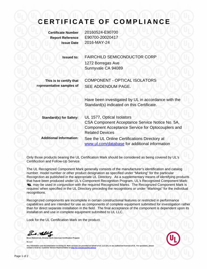
C E R T I F I C A T E O F C O M P L I A N C ECertificate Number 20140530-E90700
Report Reference E90700-19981117Issue Date 2014-MAY-30
William R. Carney, Director, North American Certification Programs
UL LLC
Any information and documentation involving UL Mark services are provided on behalf of UL LLC (UL) or any authorized licensee of UL. For questions, please contact a local UL Customer Service Representative at www.ul.com/contactus
Page 1 of 2
FAIRCHILD SEMICONDUCTOR CORPIssued to:
3030 ORCHARD PKYSAN JOSE CA 95134
COMPONENT – OPTICAL ISOLATORSThis is to certify thatrepresentative samples of SEE ADDENDUM
Have been investigated by UL in accordance with the Standard(s) indicated on this Certificate.
Standard(s) for Safety: UL 1577, Optical IsolatorsCSA Component Acceptance Service No. 5A“Component Acceptance Service for Optocouplers and Related Devices."
Additional Information: See the UL Online Certifications Directory atwww.ul.com/database for additional information
Only those products bearing the UL Recognized Component Mark should be considered as being covered by UL's Recognition and Follow-Up Service.The UL Recognized Component Mark generally consists of the manufacturer’s identification and catalog number, model number or other product designation as specified under “Marking” for the particular Recognition as published in the appropriate UL Directory. As a supplementary means of identifying products that have been produced under UL’s Component Recognition Program, UL’s Recognized Component Mark: , may be used in conjunction with the required Recognized Marks. The Recognized Component Mark is required when specified in the UL Directory preceding the recognitions or under “Markings” for the individual recognitions.Recognized components are incomplete in certain constructional features or restricted in performance capabilities and are intended for use as components of complete equipment submitted for investigation rather than for direct separate installation in the field. The final acceptance of the component is dependent upon its installation and use in complete equipment submitted to UL LLC.
Look for the UL Recognized Component Mark on the product.
Created by UL Document Assembler 2016-09-13 21:50:29 -05:00

C E R T I F I C A T E O F C O M P L I A N C ECertificate Number 20140530-E90700
Report Reference E90700-19981117Issue Date 2014-MAY-30
William R. Carney, Director, North American Certification Programs
UL LLC
Any information and documentation involving UL Mark services are provided on behalf of UL LLC (UL) or any authorized licensee of UL. For questions, please contact a local UL Customer Service Representative at www.ul.com/contactus
Page 2 of 2
This is to certify that representative samples of the product as specified on this certificate were tested according to the current UL requirements.
USR – Double Protection Optical Isolators, Construction Code “Q”, six pin devices.
Types H74C1, H74C2, MCA230, MCA231, MCA255, MCS2, MCS2400, MCT2, MCT2E, MCT26, MCT210, MCT271 through MCT275, MCT277, SOI-8, 107P10139, 107P10124, 374-0135, 385-0002, 480-1 through 480-4, 480-6, 162 18-0 through -8, 162-19-0 through -8, 326802, 335522, 404325, 1853010MTE, 12852153, 0355L1. May be followed by additional numbers and/or letters.
Types 01S63, 01S63A, 01S67, 01S67A, TLP531, TLP532. May be followed by additional numbers and/or letters.
Types 4N, CNX, CNY, H11, IL, MC, OPI, SCS, SOC, TIL, may be followed by additional letters or numbers; Type MOC, may be followed by additional numbers and/or letters.
Created by UL Document Assembler 2016-09-13 21:50:29 -05:00
File E90700 Project 98SC45471
November 17, 1998
REPORT
ON
COMPONENT - OPTICAL ISOLATORS
QT Optoelectronics Sunnyvale, California
Copyright 1998 Underwriters Laboratories Inc. Underwriters Laboratories Inc. authorizes the above named company to reproduce this Report provided it is reproduced in its entirety. Underwriters Laboratories Inc. authorizes the above named company to reproduce that portion of this Report consisting of this Cover Page through Page 2.
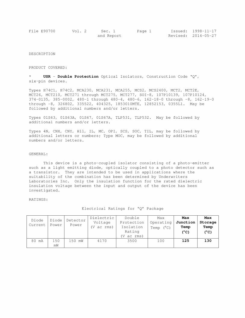
File E90700 Vol. 2 Sec. 1 Page 1 Issued: 1998-11-17 and Report Revised: 2014-05-27 DESCRIPTION PRODUCT COVERED: * USR – Double Protection Optical Isolators, Construction Code “Q”, six-pin devices. Types H74C1, H74C2, MCA230, MCA231, MCA255, MCS2, MCS2400, MCT2, MCT2E, MCT26, MCT210, MCT271 through MCT275, MCT277, SOI-8, 107P10139, 107P10124, 374-0135, 385-0002, 480-1 through 480-4, 480-6, 162-18-0 through -8, 162-19-0 through -8, 326802, 335522, 404325, 1853010MTE, 12852153, 0355L1. May be followed by additional numbers and/or letters. Types 01S63, 01S63A, 01S67, 01S67A, TLP531, TLP532. May be followed by additional numbers and/or letters. Types 4N, CNX, CNY, H11, IL, MC, OPI, SCS, SOC, TIL, may be followed by additional letters or numbers; Type MOC, may be followed by additional numbers and/or letters. GENERAL: This device is a photo-coupled isolator consisting of a photo-emitter such as a light emitting diode, optically coupled to a photo detector such as a transistor. They are intended to be used in applications where the suitability of the combination has been determined by Underwriters Laboratories Inc. Only the insulation function for the rated dielectric insulation voltage between the input and output of the device has been investigated. RATINGS:
Electrical Ratings for “Q” Package
Diode Current
Diode Power
Detector Power
Dielectric Voltage
(V ac rms)
Double Protection Isolation Rating
(V ac rms)
Max Operating Temp (C)
Max Junction Temp (C)
Max Storage Temp (C)
80 mA 150 mW
150 mW 4170 3500 100 125 130

File E90700 Vol. 2 Sec. 1 Page 2 Issued: 1998-11-17 and Report Revised: 2009-06-10 ENGINEERING CONSIDERATIONS (NOT FOR FIELD REPRESENTATIVE'S USE): These devices are opticallly coupled isolating switches with gallium arsenide light emitting diodes optically coupled to photo detectors. The solid state portion of these devices is encapsulated in a silicon or epoxy compound. The light emitting diode and detector are separated by an insulating window. Internal “chips” are provided with terminals molded into the enclosure. Use - For use only in products where the acceptability of the combination is determined by Underwriters Laboratories Inc. Conditions of Acceptability - Each device shall be reviewed with respect to the following conditions of acceptability: 1. The short circuit interrupting capacity, or behavior under short
circuit conditions, has not been evaluated for these devices. Accordingly, the end-use circuit should contain suitable impedance to eliminate the end for such testing, or appropriate tests should be conducted.
2. The device shall be installed in compliance with the enclosure,
mounting, spacings, and segregation requirements of the ultimate application. No spacings are specified for the device.
3. The outer surface temperature ratings recorded above shall be
acceptable in the ultimate application. 4. The suitability of use when exposed to oil, chemicals and the like has
not been determined by this investigation. 5. The suitability of the connections shall be determined in the end-use
application. 6. The capability of the device to control a load has not been
investigated. 7. The suitability of the device to be mounted over dead metal or metal of
opposite polarity has not been investigated. 8. These devices are intended for factory wiring only. 9. For single protection devices, the insulation to the case has not been
evaluated. For double protection devices, the insulation to the case has been evaluated to the isolation voltage specified in the ratings table.
10. In addition to meeting single protection requirements, double protection optical isolators have also been investigated for use in up to 250 V, 50/60 Hz circuits in audio, video, and similar equipment in applications in which breakdown of the optical isolator may result in a risk of fire, electrical shock, or injury to persons.

File E90 CONSTRUC Thdescript Al Thexcept w Comaterial Ma
device wabove orthere issee Sec.
0700
CTION DETA
he producttion.
ll dimensi
he generalwhere vari
orrosion Pl or are p
arkings -
was shipper before as a 3 or 4. Gen., an
Vol. 2
AILS:
t shall be
ions are ap
l design, siations are
Protection plated or p
Each devic
ed is markea 3 or 4 di4 digit datnd is follo
Sec. 1and Repo
construct
pproximate
shape and e specific
- All ferpainted as
ce or the
ed with thigit type te code whowed by a
1 Port
ted in acco
e unless sp
arrangemencally descr
rrous partss corrosion
smallest s
he company’designatiohich may be“Q” for th
Page 3
ordance wi
pecified a
nt shall bribed.
s are of cn protecti
shipping c
’s name oron. Belowe precededhe constru
IssuedRevised
ith the fol
as “max” or
be as illus
corrosion rion.
carton in w
r “QTC” or w the type d by the fauction syst
d: 1998-1d: 2007-0
llowing
r “min”.
strated,
resistant
which the
“Q” or designatiactory codtem.
11-17 03-05
ion, de,
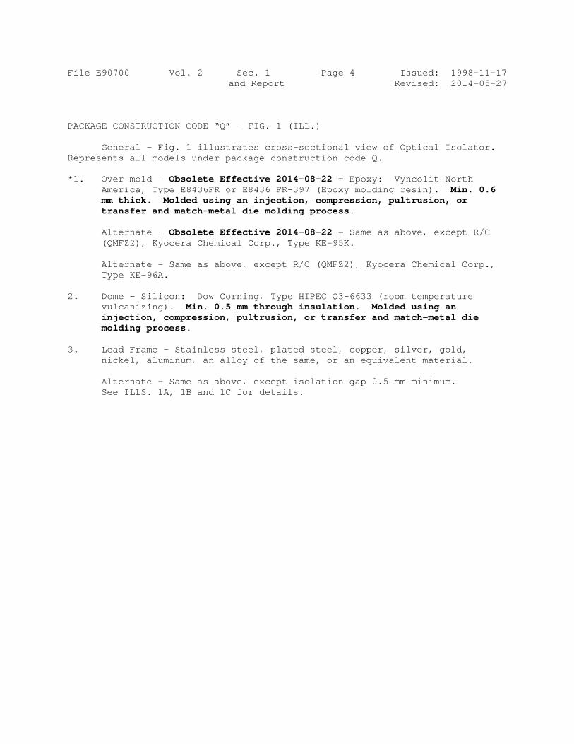
File E90700 Vol. 2 Sec. 1 Page 4 Issued: 1998-11-17 and Report Revised: 2014-05-27 PACKAGE CONSTRUCTION CODE “Q” - FIG. 1 (ILL.) General - Fig. 1 illustrates cross-sectional view of Optical Isolator. Represents all models under package construction code Q. *1. Over-mold – Obsolete Effective 2014-08-22 - Epoxy: Vyncolit North
America, Type E8436FR or E8436 FR-397 (Epoxy molding resin). Min. 0.6 mm thick. Molded using an injection, compression, pultrusion, or transfer and match-metal die molding process.
Alternate - Obsolete Effective 2014-08-22 - Same as above, except R/C
(QMFZ2), Kyocera Chemical Corp., Type KE-95K. Alternate - Same as above, except R/C (QMFZ2), Kyocera Chemical Corp.,
Type KE-96A. 2. Dome - Silicon: Dow Corning, Type HIPEC Q3-6633 (room temperature
vulcanizing). Min. 0.5 mm through insulation. Molded using an injection, compression, pultrusion, or transfer and match-metal die molding process.
3. Lead Frame - Stainless steel, plated steel, copper, silver, gold,
nickel, aluminum, an alloy of the same, or an equivalent material. Alternate – Same as above, except isolation gap 0.5 mm minimum.
See ILLS. 1A, 1B and 1C for details.

Page
C
William R. Carn UL LLC Any informationcontact a local
e 1 of 2
re
Only thosconsidereCanadian
The UL Rcatalog nRecognithave beebe used ispecified UL Recomanufact“Marking”
Recognizcapabilitiethan for dinstallatio Look for t
C E R T
Certific
Repo
ney, Director, North Amer
n and documentation invUL Customer Service Re
This is t
epresentative
Standard(s
Additional
se products beaed as being covn requirements
Recognized Cnumber, modeion as publishe
en produced unin conjunction win the UL Dire
ognized Compoturer’s identific” for the particu
zed componentes and are intedirect separate on and use in c
the UL Recogn
T I F I C
cate Number
ort Reference
Issue Date
rican Certification Progra
volving UL Mark servicesepresentative at www.ul.
Issued to
o certify that
e samples of
s) for Safety
Information
aring the UL Rvered by UL's
s.
omponent Marel number or oed in the appronder UL’s Comwith the requireectory precedinonent Mark foration and cataular Recognitio
ts are incompleended for use a
installation in tcomplete equip
nized Compone
A T E
r 201405e E90700e 2014-M
ams
s are provided on behalf com/contactus
: FAIRC
3030 OSAN JO
t
f
COMP
SEE A
Have bStanda
: UL 157CSA C“CompRelated
: See thewww.u
Recognized ComRecognition an
rk for the U.S.other product dopriate UL Direcponent Recogned Recognizedng the recognitr Canada conslog number, mn as published
ete in certain coas componentsthe field. The fment submitted
ent Mark on the
O F C
530-E907000-20010413
MAY-30
of UL LLC (UL) or any au
HILD SEM
ORCHARD OSE CA 95
ONENT – O
DDENDUM
been investard(s) indica
77, Optical Component
onent Acced Devices."
e UL Onlinel.com/datab
mponent Marksnd Follow-Up S
. generally condesignation asctory. As a supnition Programd Marks. The Rtions or under sists of the ULodel number o
d in the appropr
onstructional fes of complete efinal acceptancd to UL LLC.
e product.
C O M P
0 3
uthorized licensee of UL
ICONDUCT
PKY 5134
OPTICAL IS
M
igated by Uated on this
Isolators Acceptance
eptance Se"
e Certificatibase for ad
s for the U.S. aService and me
nsists of the ms specified undpplementary m, UL’s Recogn
Recognized Co“Markings” for L Recognized or other producriate UL Directo
eatures or restrquipment subm
ce of the compo
P L I A N
. For questions, please
TOR CORP
SOLATORS
UL in accords Certificate
e Service Nrvice for Op
ions Directodditional info
and Canada sheeting the appro
manufacturer’s der “Marking”
means of identifized Compone
omponent Markthe individual Mark for Can
ct designation aory.
ricted in performmitted for invesonent is depen
N C E
P
S
dance with e.
No. 5A ptocouplers
ory at ormation
ould be opriate U.S. an
identification afor the particu
fying products tent Mark: , mk is required whrecognitions. Tada: and
as specified un
mance stigation rather ndent upon its
the
s and
nd
and ular that may hen The the
nder
Page
C
William R. Carn UL LLC Any informationcontact a local
e 2 of 2
This is toaccordin USR, CNFODM45 USR, CN USR - SHMHA28
C E R T
Certific
Repo
ney, Director, North Amer
n and documentation invUL Customer Service Re
o certify that rng to the curre
NR - Single P53, FODM806
NR - Single P
Single Protect81# and HMH
T I F I C
cate Number
ort Reference
Issue Date
rican Certification Progra
volving UL Mark servicesepresentative at www.ul.
representativeent UL require
Protection Opt61, FODM61
Protection Opt
ion Optical IsHAA280#,
A T E
r 201405e E90700e 2014-M
ams
s are provided on behalf com/contactus
e samples of ements.
tical Isolators1, FODM807
tical Isolators
olaters, Pack
O F C
530-E907000-20010413
MAY-30
of UL LLC (UL) or any au
the product a
, Package Co1.
, Models FOD
kage Construc
C O M P
0 3
uthorized licensee of UL
as specified o
onstruction Co
DM8801 and
ction Code M
P L I A N
. For questions, please
on this certific
ode M, Mode
FODM8811.
1, Models HM
N C E
ate were test
ls FODM452,
MHA2801#,
ed
,

File E90700 Project 01SC02681
April 13, 2001
REPORT ON
COMPONENT – OPTICAL ISOLATORS
Fairchild Semiconductor Corp. San Jose, California
Copyright © 1998 Underwriters Laboratories Inc. Underwriters Laboratories Inc. authorizes the above-named company to reproduce that portion of this Report consisting of this Cover Page through Page 2.

File E90700 Vol. 2 Sec. 2 Page 1 Issued: 2001-04-13 and Report Revised: 2014-05-27 DESCRIPTION PRODUCT COVERED: * USR, CNR - Single Protection Optical Isolators, Package Construction Code M, Models FODM452, FODM453, FODM8061, FODM611, FODM8071. USR, CNR - Single Protection Optical Isolators, Models FODM8801 and FODM8811. * USR - Single Protection Optical Isolaters, Package Construction Code M1, Models HMHA2801#, HMHA281# and HMHAA280#, GENERAL: These devices are photocoupled isolators consisting of a photo-emitter such as a light emitting diode, optically coupled to a photo detector such as a transistor. They are intended to be used in applications where the suitability of the combination has been determined by Underwriters Laboratories Inc. Only the insulation function for the rated dielectric insulation voltage between the input and output of the device has been investigated. Use – For use only in products where the acceptability of the combination is determined by Underwriters Laboratories Inc. Ratings:
Current (mA) Power (mW) Max Operating
Max Junction
Max Storage
Package Code/ Models
Diode Detector Diode Detector Isolation Voltage
Temperature (C)
Temperature (C)
Temperature (C)
*
*M/ FODM452, FODM453
50 80 70 150 3750
110 125 125
M1/ HMHA2801#, HMHA281#, HMHAA280#
50 50 60 150 3750 100 125 125
M/ FODM8061, FODM611
20 50 40 85 3750 110 125 125
M/ FODM8071 20 10 40 70 3750 110 125 125 FODM8801, FODM8811
30 50 40 150 3750 125 150 150
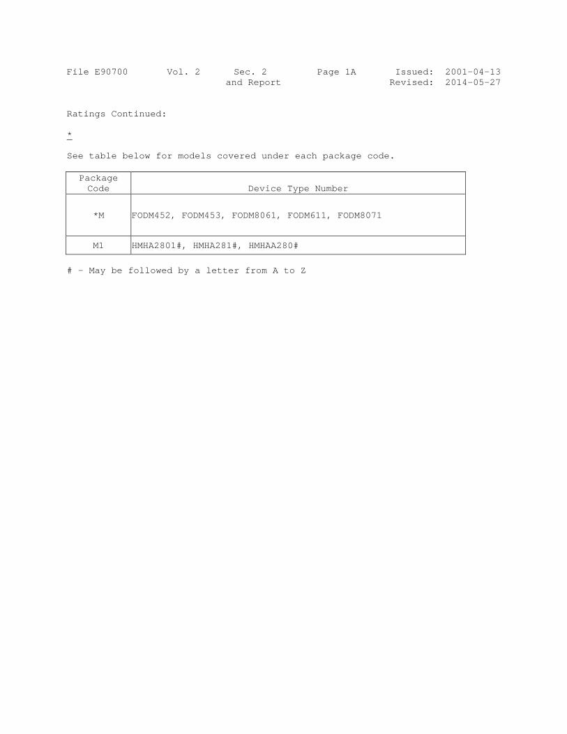
File E90700 Vol. 2 Sec. 2 Page 1A Issued: 2001-04-13 and Report Revised: 2014-05-27 Ratings Continued: * See table below for models covered under each package code.
Package Code Device Type Number
*M FODM452, FODM453, FODM8061, FODM611, FODM8071
M1 HMHA2801#, HMHA281#, HMHAA280#
# - May be followed by a letter from A to Z

File E90700 Vol. 2 Sec. 2 Page 2 Issued: 2001-04-13 and Report Revised: 2011-01-04 ENGINEERING CONSIDERATIONS (NOT FOR FIELD REPRESENTATIVE’S USE): These devices are optically coupled isolating switches with light emitting diodes optically coupled to photo detectors. The solid state portion of these devices is encapsulated in a silicon or epoxy compound. The light emitting diode and detector are separated by an insulating window. Internal “chips” are provided with terminals molded into the enclosure. Conditions of Acceptability – Each device shall be reviewed with respect to the following conditions of acceptability: 1. The capability of the device to control a load has not been
investigated. 2. These devices should be installed in a suitable end product enclosure. 3. The maximum temperature on the case should not exceed the maximum
operating temperature rating specified in the ratings table. 4. For single protection devices, the insulation to the case has not been
evaluated. For double protection devices, the insulation to the case has been evaluated to the isolation voltage specified in the ratings table.
5. In addition to meeting single protection requirements, double
protection optical isolators have also been investigated for use in up to 250 V, 50/60 Hz circuits in audio, video, and similar equipment in applications in which breakdown of the optical isolator may result in a risk of fire, electrical shock, or injury to persons.

File E90700 Vol. 2 Sec. 2 Page 3 Issued: 2001-04-13 and Report Revised: 2009-11-12 CONSTRUCTION DETAILS: General – The product shall be constructed in accordance with the following description. All dimensions are approximate unless specified as “max” or “min”. The general design, shape and arrangement shall be as illustrated, except where variations are specifically described. Corrosion Protection – All ferrous parts are of corrosion resistant material or are plated or painted as corrosion protection. Markings – See Section General for Markings. Model Differences – All models have identical insulation systems. The only difference is the leadframe design or the size of the IC devices. Abbreviation – R/C – Recognized Component Pin Connections – See ILLS. 4 and 4A for details. Package Dimensions – See ILLS. 5 and 5A for details. Leadframe Design – See ILLS. 3, 3A, 6, 6A, 7, 8, 8A, 9, 10, 11, and 12,
for details. For Engineering use only. See illustration 14 for package dimensions, leadframe design and pin connections for models type FODM8061, FODM611, FODM8071, FODM452 and FODM453.
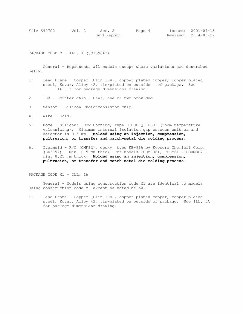
File E90700 Vol. 2 Sec. 2 Page 4 Issued: 2001-04-13 and Report Revised: 2014-05-27 PACKAGE CODE M – ILL. 1 (SO159843) General – Represents all models except where variations are described below. 1. Lead Frame – Copper (Olin 194), copper-plated copper, copper-plated
steel, Kovar, Alloy 42, tin-plated on outside of package. See ILL. 5 for package dimensions drawing.
2. LED – Emitter chip – GaAs, one or two provided. 3. Sensor – Silicon Phototransistor chip. 4. Wire – Gold. 5. Dome – Silicon: Dow Corning, Type HIPEC Q3-6633 (room temperature
vulcanizing). Minimum internal isolation gap between emitter and detector is 0.5 mm. Molded using an injection, compression, pultrusion, or transfer and match-metal die molding process.
6. Overmold – R/C (QMFZ2), epoxy, type KE-96A by Kyocera Chemical Corp.
(E43857). Min. 0.5 mm thick. For models FODM8061, FODM611, FODM8071, min. 0.25 mm thick. Molded using an injection, compression, pultrusion, or transfer and match-metal die molding process.
PACKAGE CODE M1 - ILL. 1A General - Models using construction code M1 are identical to models using construction code M, except as noted below. 1. Lead Frame - Copper (Olin 194), copper-plated copper, copper-plated
steel, Kovar, Alloy 42, tin-plated on outside of package. See ILL. 5A for package dimensions drawing.

File E90700 Vol. 2 Sec. 2 Page 5 Issued: 2001-04-13 and Report Revised: 2014-05-27
This page Replace page 5

File E90700 Vol. 2 Sec. 2 Page 6 Issued: 2001-04-13 and Report Revised: 2014-05-27 MODEL FODM8801 ILL. 15 General – Model FODM8801 represents models FODM8811, except as noted below. 1. Emitter – [LED] input. 2. Sensor – Silicon Phototransistor chip. 3. Lead Frame – Metal employed for current carrying parts shall be of
stainless steel, silver, gold, copper, nickel, aluminum, an alloy of the same, or an equivalent material.
4. Bond Wire – Metal employed for current carrying parts shall be of
stainless steel, silver, gold, copper, nickel, aluminum, an alloy of the same, or an equivalent material.
5. Dome – Silicon: Dow Corning, Type HIPEC Q3-6633 (room temperature
vulcanizing). Minimum 0.5 mm through insulation spacing between the input and output circuits.
*6. Outermold – R/C (QMFZ2), epoxy, type KE-96A by Kyocera Chemical Corp.
(E43857).
Page
C
Bruce Mahrenh UL LLC Any informationcontact a local
e 1 of 2
re
Only thoCertifica The UL number,Recognithat hav
, mayrequiredrecognit Recognicapabilitthan for installati Look for
C E R T
Certific
Repo
holz, Director North Amer
n and documentation invUL Customer Service Re
This is t
epresentative
Standard(s
Additional
ose products bation and Follo
Recognized C, model numbition as publise been produy be used in cd when specifions.
ized componeties and are indirect separaon and use in
r the UL Certif
T I F I C
cate Number
ort Reference
Issue Date
rican Certification Progra
volving UL Mark servicesepresentative at http://ul.
Issued to
o certify that
e samples of
s) for Safety
Information
bearing the Uow-Up Servic
Component Mber or other prshed in the apuced under ULconjunction wied in the UL
ents are incomntended for uate installationn complete eq
fication Mark
A T E
r 201605e E90700e 2016-M
am
s are provided on behalf .com/aboutul/locations/
: FAIRC
1272 BSunnyv
t
f
COMP
SEE A
Have bStanda
: UL 157CSA CCompoRelated
: See thewww.u
UL Certificatioce.
Mark generallyroduct designppropriate ULL’s Compone
with the requireDirectory pre
mplete in certse as compon in the field. quipment sub
on the produ
O F C
524-E907000-20020417
MAY-24
of UL LLC (UL) or any au
HILD SEM
Borregas Avvale CA 94
ONENT - O
DDENDUM
been investard(s) indica
77, Optical Component onent Accepd Devices
e UL Onlinel.com/datab
n Mark shoul
y consists of tnation as specL Directory. Aent Recognitioed Recognize
eceding the re
tain constructnents of comThe final acc
bmitted to UL
ct.
C O M P
0 7
uthorized licensee of UL
ICONDUCT
ve 089
OPTICAL IS
M PAGE.
igated by Uated on this
Isolators Acceptanceptance Serv
e Certificatibase for ad
d be conside
the manufactcified under “M
As a supplemeon Program, Ued Marks. Thecognitions or
tional featuresplete equipm
ceptance of thLLC.
P L I A N
. For questions, please
TOR CORP
SOLATORS
UL in accords Certificate
e Service Nvice for Op
ions Directodditional info
red as being
turer’s identifiMarking” for tentary meansUL’s Recognizhe Recognizedr under “Mark
s or restrictedent submitted
he componen
N C E
P
S
dance with e.
Notice No. 5ptocouplers
ory at ormation
covered by U
cation and cathe particular s of identifyingzed Componed Component
kings” for the i
d in performand for investigat is dependen
the
5A, and
UL's
atalog
g products ent Mark: t Mark is individual
nce ation rather nt upon its

Page
C
Bruce Mahrenh UL LLC Any informationcontact a local
e 2 of 2
This is toaccordin Single P6N138MFOD274FOD318HCPL26HCPL-4
C E R T
Certific
Repo
holz, Director North Amer
n and documentation invUL Customer Service Re
o certify that rng to the curre
Protection OptM, 6N139M, F41B, FOD27482, FOD3184601M, HCPL2502, HCPL-4
T I F I C
cate Number
ort Reference
Issue Date
rican Certification Progra
volving UL Mark servicesepresentative at http://ul.
representativeent UL require
tical Isolator, OD250L, FO1C, FOD2743, FOD4506M
2611M, HCPL503M. May
A T E
r 201605e E90700e 2016-M
am
s are provided on behalf .com/aboutul/locations/
e samples of ements.
Construction D260L, FOD23A, FOD2743, FOD8071, M
L2630M, HCPbe followed b
O F C
524-E907000-20020417
MAY-24
of UL LLC (UL) or any au
the product a
Code “B”, Mo270L, FOD223B, FOD2743MID400M, HCPL2631M, HCby additional n
C O M P
0 7
uthorized licensee of UL
as specified o
odels 6N135M200, FOD27113C, FOD3120CPL-2503M, HCPL2730M, Hnumbers and
P L I A N
. For questions, please
on this certific
M, 6N136M, 61, FOD2711A
0, FOD3150, FHCPL2530M,CPL2731, HC/or letters.
N C E
ate were test
6N137M, A, FOD2741AFOD3180, HCPL2531M
CPL3700M,
ed
A,
M,

File E90700 Project 02SC04973
April 17, 2002
REPORT ON
COMPONENT - OPTICAL ISOLATORS
Fairchild Semiconductor Corp. San Jose, California
Copyright 2002 Underwriters Laboratories Inc. Underwriters Laboratories Inc. authorizes the above-named company to reproduce this Report provided it is reproduced in its entirety. Underwriters Laboratories Inc. authorizes the above-named company to reproduce that portion of this Report consisting of this Cover Page through Page 2.
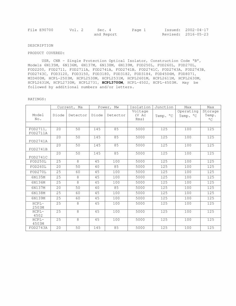
File E90700 Vol. 2 Sec. 4 Page 1 Issued: 2002-04-17 and Report Revised: 2016-05-23 DESCRIPTION PRODUCT COVERED: USR, CNR – Single Protection Optical Isolator, Construction Code “B”, Models 6N135M, 6N136M, 6N137M, 6N138M, 6N139M, FOD250L, FOD260L, FOD270L, FOD2200, FOD2711, FOD2711A, FOD2741A, FOD2741B, FOD2741C, FOD2743A, FOD2743B, FOD2743C, FOD3120, FOD3150, FOD3180, FOD3182, FOD3184, FOD4506M, FOD8071, MID400M, HCPL-2503M, HCPL2530M, HCPL2531M, HCPL2601M, HCPL2611M, HCPL2630M, HCPL2631M, HCPL2730M, HCPL2731, HCPL3700M, HCPL-4502, HCPL-4503M. May be followed by additional numbers and/or letters. RATINGS:
Model No.
Current, Ma Power, Mw Isolation Junction Max Max
Diode
Detector
Diode
Detector Voltage (V Ac Rms)
Temp. C
Operating Temp. C
Storage Temp. C
FOD2711, FOD2711A
20 50 145 85 5000 125 100 125
FOD2741A
20 50 145 85 5000 125 100 125
FOD2741B
20 50 145 85 5000 125 100 125
FOD2741C
20 50 145 85 5000 125 100 125
FOD250L 25 8 45 100 5000 125 100 125 FOD260L 20 50 40 85 5000 125 100 125 FOD270L 25 60 45 100 5000 125 100 125 6N135M 25 8 45 100 5000 125 100 125 6N136M 25 8 45 100 5000 125 100 125 6N137M 20 50 40 85 5000 125 100 125 6N138M 25 60 45 100 5000 125 100 125 6N139M 25 60 45 100 5000 125 100 125 HCPL-2503M
25 8 45 100 5000 125 100 125
HCPL-4502
25 8 45 100 5000 125 100 125
HCPL-4503M
25 8 45 100 5000 125 100 125
FOD2743A 20 50 145 85 5000 125 100 125
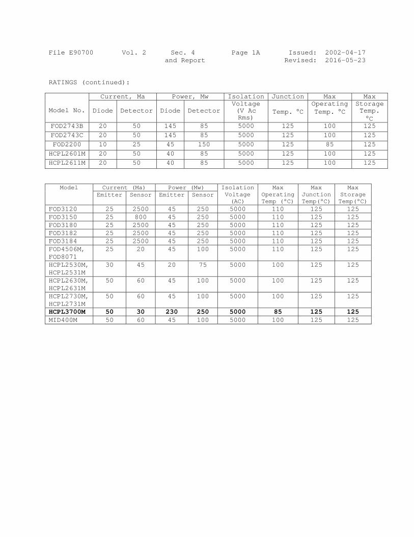
File E90700 Vol. 2 Sec. 4 Page 1A Issued: 2002-04-17 and Report Revised: 2016-05-23 RATINGS (continued):
Model No.
Current, Ma Power, Mw Isolation Junction Max Max
Diode
Detector
Diode
Detector Voltage (V Ac Rms)
Temp. C
Operating Temp. C
Storage Temp. C
FOD2743B 20 50 145 85 5000 125 100 125 FOD2743C 20 50 145 85 5000 125 100 125 FOD2200 10 25 45 150 5000 125 85 125 HCPL2601M 20 50 40 85 5000 125 100 125 HCPL2611M 20 50 40 85 5000 125 100 125
Model Current (Ma) Power (Mw) Isolation Voltage (AC)
Max Operating Temp (°C)
Max Junction Temp(°C)
Max Storage Temp(°C)
Emitter Sensor Emitter Sensor
FOD3120 25 2500 45 250 5000 110 125 125 FOD3150 25 800 45 250 5000 110 125 125 FOD3180 25 2500 45 250 5000 110 125 125 FOD3182 25 2500 45 250 5000 110 125 125 FOD3184 25 2500 45 250 5000 110 125 125 FOD4506M, FOD8071
25 20 45 100 5000 110 125 125
HCPL2530M, HCPL2531M
30 45 20 75 5000 100 125 125
HCPL2630M, HCPL2631M
50 60 45 100 5000 100 125 125
HCPL2730M, HCPL2731M
50 60 45 100 5000 100 125 125
HCPL3700M 50 30 230 250 5000 85 125 125 MID400M 50 60 45 100 5000 100 125 125
File E90700 Vol. 2 Sec. 4 Page 2 Issued: 2002-04-17 and Report Revised: 2015-03-03 ENGINEERING CONSIDERATIONS (NOT FOR FIELD REPRESENTATIVE’S USE): These devices are optically coupled isolating switches consisting of a photo-emitter such as light emitting diodes optically coupled to photo detectors such as transistors. The solid state portion of these devices is encapsulated in a silicone or epoxy compound. The light emitting diode and detector are separated by an insulating window. Internal “chips” are provided with terminals molded into the enclosure. Only the insulation function for the rated Dielectric Insulation Voltage between the input and output of the device has been investigated. Use - For use only in products where the acceptability of the combination is determined by Underwriters Laboratories Inc. USR indicates that the optical isolators have been evaluated to the US Standard for Optical Isolators, UL 1577, 5th Edition. CNR indicates that the optical isolators have been evaluated to the Canadian Standard for Optical Isolators, Component Acceptance Service No. 5A. Conditions of Acceptability - Each device shall be reviewed with respect to the following conditions of acceptability: 1. The capability of the device to control a load has not been
investigated. 2. These devices should be installed in a suitable end product enclosure. 3. The maximum temperature on the case should not exceed the maximum
operating temperature rating specified in the ratings table. 4. For single protection devices, the insulation to the case has not been
evaluated. For double protection devices, the insulation to the case has been evaluated to the isolation voltage specified in the ratings table.
5. In addition to meeting single protection requirements, double
protection optical isolators have also been investigated for use in up to 250 V, 50/60 Hz circuits in audio, video, and similar equipment in applications in which breakdown of the optical isolator may result in a risk of fire, electrical shock, or injury to persons.

File E90 CONSTRUC Geillustradimensio Comaterial
Markingsabove orafter a Markings Example
25VYY
Nomencla
27
YY
B:
V:
Spmanufactor graph 1. Ma
ph 2. A
tera
3. Th 4. De
0700
CTION DETA
eneral - Tated in thons are ap
orrosion Pl or are p
s – – Eacr before tfour-digis may appe
device ma
50L YXXB
ature:
712: Denodevi
YXX: Deno wher
: Deno
: Opti
pecificatituring fachic format
aximum conhoto-emitt
dielectrierminals. atings abo
he maximum
erating sp
Vol. 2
AILS:
The generalhe followinpproximate,
Protection plated or p
ch componenthe type deit date codear on the
arking:
or
otes deviceice. The p
otes Date cre YY = Two XX = Two
otes Packag
ional - Den
ion Sheet -cility and t:
ntinuous poter and the
ic insulati This shouove.
m operating
pecificatio
Sec. 4and Repo
l design, ng descrip, unless s
– All ferpainted as
nt is markesignationde. See tsmallest
r Q denote
e type. Tprefix ‘FO
code, o digit yeo digit wo
ge Code B
notes VDE
- Specificshall con
ower, a cue photo-de
ion-voltaguld be the
g temperat
on related
4 Port
shape and ptive pagesspecified a
rrous partss corrosion
ked with thn. The pacthe nomenclshipping c
s Company
The ‘250L’ OD’ will be
ear code, Eork week co
0884 appro
cation sheentain the f
urrent and etector.
ge rating be same as t
ture of the
d to ambien
Page 3
arrangemes and illuas “maximu
s are of cn protecti
he companyckage codelature belcontainer.
logo.
is the mae ignored
Example: 0ode
oval mark
et shall bfollowing
a voltage
between inthe isolat
e device c
nt tempera
IssuedRevised
ent shall bustrations.um” or “min
corrosion rion.
y’s name ore will be slow for mor
arking for in the dev
03 indicate
be availablinformatio
e rating fo
nput and oution V ac i
case.
atures.
d: 2003-0d: 2003-0
be as . All nimum."
resistant
r “Q” or specified re details
the FOD25vice markin
es year 20
le at the on in tabu
or both th
utput in the
04-17 09-26
,
s.
50L ng.
003.
ular
he

File E90700 Vol. 2 Sec. 4 Page 4 Issued: 2002-04-17 and Report Revised: 2012-08-22
Model Differences - All models have identical insulation systems. The only difference is the leadframe design or the size of the IC devices. Models FOD2743A/B/C are identical to models FOD2741A/B/C except the orientation of the die inside the package is reversed. Abbreviation - R/C = Recognized Component. Pin Connections - See ILL. 1, 1A for details. Package Dimensions - See ILLS. 2, 3 and 4, 5 for details. Model FOD318X is identical to Model FOD2711A except for the leadframe design or the size of the IC devices. Models FOD4506M and FOD8071 are using the same die. Model FOD8071 is intended to work on a 3.3 and 5V supply while FOD4506M is intended to work only on a 5V supply voltage.
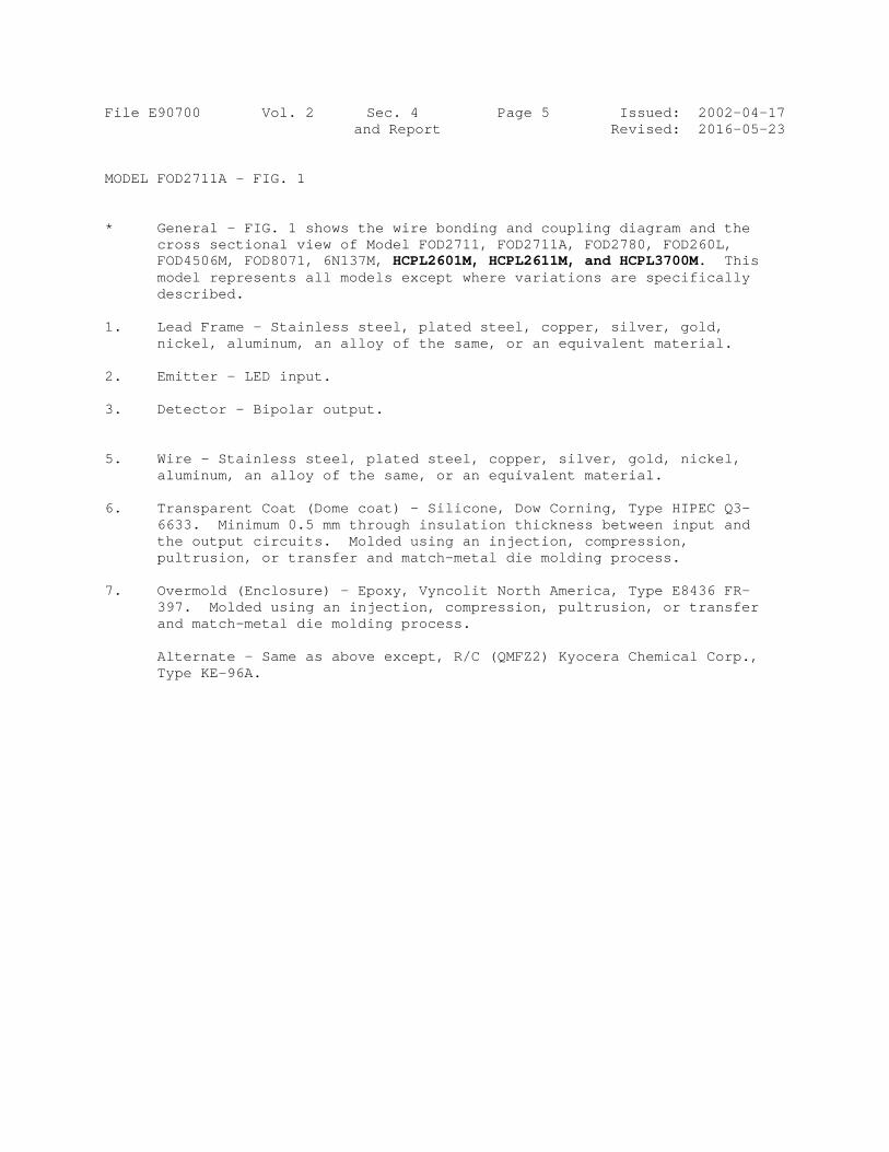
File E90700 Vol. 2 Sec. 4 Page 5 Issued: 2002-04-17 and Report Revised: 2016-05-23 MODEL FOD2711A - FIG. 1 * General – FIG. 1 shows the wire bonding and coupling diagram and the
cross sectional view of Model FOD2711, FOD2711A, FOD2780, FOD260L, FOD4506M, FOD8071, 6N137M, HCPL2601M, HCPL2611M, and HCPL3700M. This model represents all models except where variations are specifically described.
1. Lead Frame – Stainless steel, plated steel, copper, silver, gold,
nickel, aluminum, an alloy of the same, or an equivalent material. 2. Emitter – LED input. 3. Detector – Bipolar output. 5. Wire - Stainless steel, plated steel, copper, silver, gold, nickel,
aluminum, an alloy of the same, or an equivalent material. 6. Transparent Coat (Dome coat) – Silicone, Dow Corning, Type HIPEC Q3-
6633. Minimum 0.5 mm through insulation thickness between input and the output circuits. Molded using an injection, compression, pultrusion, or transfer and match-metal die molding process.
7. Overmold (Enclosure) - Epoxy, Vyncolit North America, Type E8436 FR-
397. Molded using an injection, compression, pultrusion, or transfer and match-metal die molding process.
Alternate - Same as above except, R/C (QMFZ2) Kyocera Chemical Corp.,
Type KE-96A.
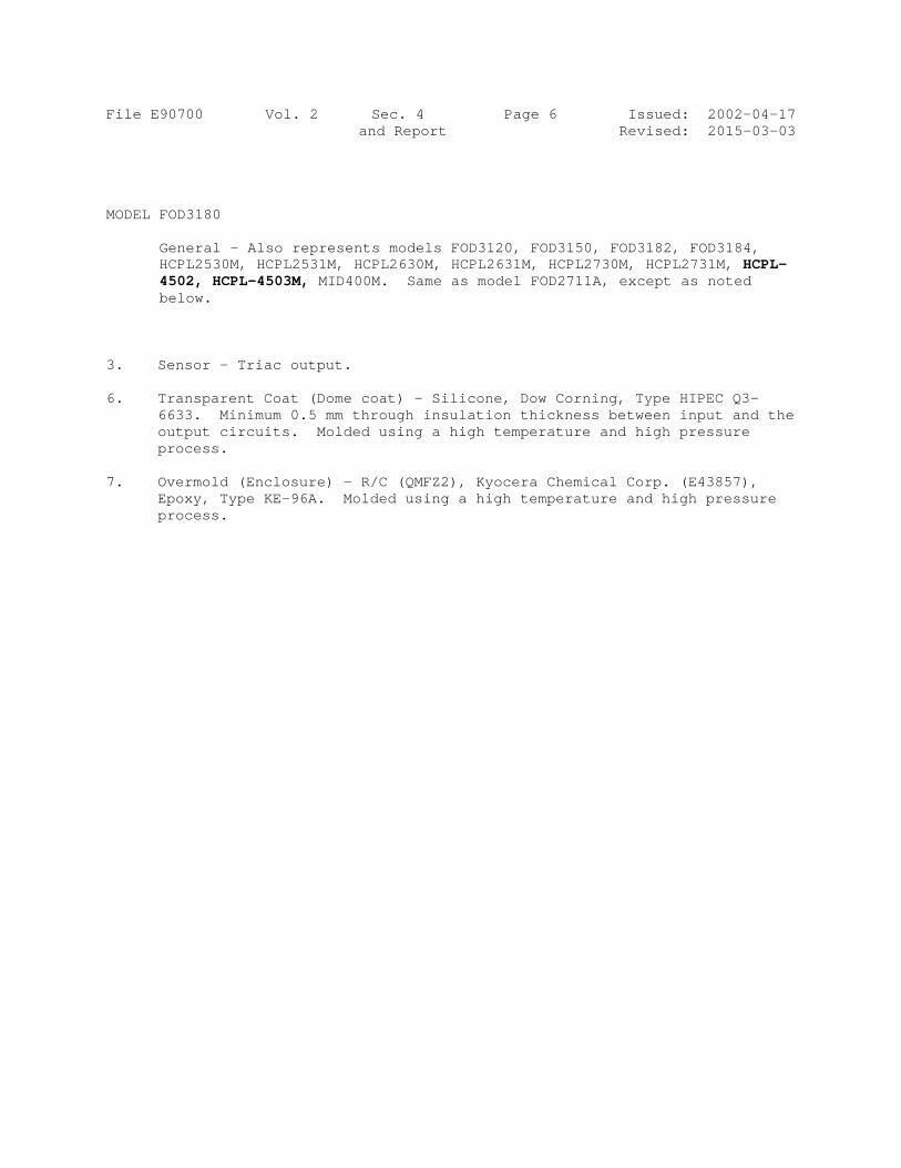
File E90700 Vol. 2 Sec. 4 Page 6 Issued: 2002-04-17 and Report Revised: 2015-03-03 MODEL FOD3180 General – Also represents models FOD3120, FOD3150, FOD3182, FOD3184,
HCPL2530M, HCPL2531M, HCPL2630M, HCPL2631M, HCPL2730M, HCPL2731M, HCPL-4502, HCPL-4503M, MID400M. Same as model FOD2711A, except as noted below.
3. Sensor – Triac output. 6. Transparent Coat (Dome coat) – Silicone, Dow Corning, Type HIPEC Q3-
6633. Minimum 0.5 mm through insulation thickness between input and the output circuits. Molded using a high temperature and high pressure process.
7. Overmold (Enclosure) - R/C (QMFZ2), Kyocera Chemical Corp. (E43857),
Epoxy, Type KE-96A. Molded using a high temperature and high pressure process.
Page
C
Bruce Mahrenh UL LLC Any informationcontact a local
e 1 of 1
re
Only thoCertifica Recognicapabilitthan for installati Look for
C E R T
Certific
Repo
holz, Assistant Chief Eng
n and documentation invUL Customer Service Re
This is t
epresentative
Standard(s
Additional
ose products bation and Follo
ized componeties and are indirect separaon and use in
r the UL Certif
T I F I C
cate Number
ort Reference
Issue Date
ineer, Global Inspection
volving UL Mark servicesepresentative at http://ul.
Issued to
o certify that
e samples of
s) for Safety
Information
bearing the Uow-Up Servic
ents are incomntended for uate installationn complete eq
fication Mark
A T E
r 201503e E90700e 2015-M
and Field Services
s are provided on behalf .com/aboutul/locations/
: FAIRC
3030 OSAN JO
t
f
COMP
Single and S1Table. All modletters
Have bStanda
: UL 157CSA CCompoRelated
: See thewww.u
UL Certificatioce.
mplete in certse as compon in the field. quipment sub
on the produ
O F C
304-E907000-20020807
MARCH-04
of UL LLC (UL) or any au
HILD SEM
ORCHARD OSE CA 95
ONENT - O
Protection , eight-pin “X” may be
dels may be
been investard(s) indica
77, Optical Component onent Accepd Devices
e UL Onlinel.com/datab
n Mark shoul
tain constructnents of comThe final acc
bmitted to UL
ct.
C O M P
0 7
uthorized licensee of UL
ICONDUCT
PKY 5134
OPTICAL IS
Optical Isodevices, Me any numbe followed b
igated by Uated on this
Isolators Acceptanceptance Serv
e Certificatibase for ad
d be conside
tional featuresplete equipm
ceptance of thLLC.
P L I A N
. For questions, please
TOR CORP
SOLATORS
olators, ConModels as shber. “Y” maby additiona
UL in accords Certificate
e Service Nvice for Op
ions Directodditional info
red as being
s or restrictedent submitted
he componen
N C E
P
S
nstruction Chown in theay be A, B, al numbers
dance with e.
Notice No. 5ptocouplers
ory at ormation
covered by U
d in performand for investigat is dependen
Code S e ratings C or D.
s and/or
the
5, and
UL's
nce ation rather nt upon its

File E90700 Project 02SC09316
August 7, 2002
REPORT ON
COMPONENT - OPTICAL ISOLATORS
Fairchild Semiconductor Corp. San Jose, California
Copyright 2002 Underwriters Laboratories Inc. Underwriters Laboratories Inc. authorizes the above-named company to reproduce this Report provided it is reproduced in its entirety. Underwriters Laboratories Inc. authorizes the above-named company to reproduce that portion of this Report consisting of this Cover Page through Page 2.

File E90700 Vol. 2 Sec. 5 Page 1 Issued: 2002-08-07 and Report Revised: 2015-03-03 DESCRIPTION PRODUCT COVERED: USR Component – Single Protection Optical Isolators, Construction Code S and S1, eight-pin devices, Models as shown in the ratings Table. “X” may be any number. “Y” may be A, B, C or D. All models may be followed by additional numbers and/or letters. RATINGS:
MODELS UNDER PACKAGE CODE S
Model No.
EMITTER DETECTOR Isolation Voltage (V ac rms)
Junction Temp C
Maximum Operating Temp. C
Maximum Storage Temp. C
Current (mA)
Power (mW)
Current (mA)
Power (mW)
FOD27X2Y 20 145 50 85 2500 125 125 125 HCPL-05XX
50 45 16 100 2500 125 125 125
HCPL-04XX
50 45 16 100 2500 125 125 125
HCPL-07XX
40 35 60 100 2500 125 125 125
HCPL-06XX
20 20 50 85 2500 125 125 125
MOC2XX 60 90 150 150 2500 125 125 150 MOCD2XX 60 90 150 150 2500 125 125 125 FOD050L 25 45 8 100 2500 125 100 125 FOD053L 25 45 8 100 2500 125 100 125 HCPL-0530
25 45 8 100 2500 125 100 125
HCPL-0531
25 45 8 100 2500 125 100 125
HCPL-0534
25 45 8 100 2500 125 100 125
HCPL-0453
25 45 8 100 2500 125 100 125
FOD070L 25 45 60 100 2500 125 100 125 FOD073L 25 45 60 100 2500 125 100 125 HCPL-0730
25 45 60 100 2500 125 100 125
HCPL-0731
25 45 60 100 2500 125 100 125
HCPL0611 20 50 40 85 2500 125 100 125 FOD060L 20 50 40 85 2500 125 100 125
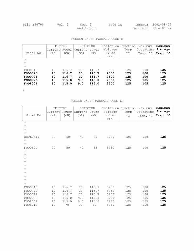
File E90700 Vol. 2 Sec. 5 Page 1A Issued: 2002-08-07 and Report Revised: 2014-05-27
MODELS UNDER PACKAGE CODE S
Model No.
EMITTER DETECTOR Isolation Voltage (V ac rms)
Junction Temp C
Maximum Operating Temp. C
Maximum Storage Temp. C
Current (mA)
Power (mW)
Current (mA)
Power (mW)
* * * FOD0710 10 116.7 10 116.7 2500 125 100 125 FOD0720 10 116.7 10 116.7 2500 125 100 125 FOD0721 10 116.7 10 116.7 2500 125 100 125 FOD072L 10 115.0 9.0 115.0 2500 125 105 125 FOD8001 10 115.0 9.0 115.0 2500 125 105 125 *
MODELS UNDER PACKAGE CODE S1
Model No.
EMITTER DETECTOR Isolation Voltage (V ac rms)
Junction Temp C
Maximum Operating Temp. C
Maximum Storage Temp. C
Current (mA)
Power (mW)
Current (mA)
Power (mW)
* * * * HCPL0611 20 50 40 85 3750 125 100 125 * * FOD060L 20 50 40 85 3750 125 100 125 * * * * * * * * * * FOD0710 10 116.7 10 116.7 3750 125 100 125 FOD0720 10 116.7 10 116.7 3750 125 100 125 FOD0721 10 116.7 10 116.7 3750 125 100 125 FOD072L 10 115.0 9.0 115.0 3750 125 105 125 FOD8001 10 115.0 9.0 115.0 3750 125 105 125 FOD8012 10 70 10 70 3750 125 110 125
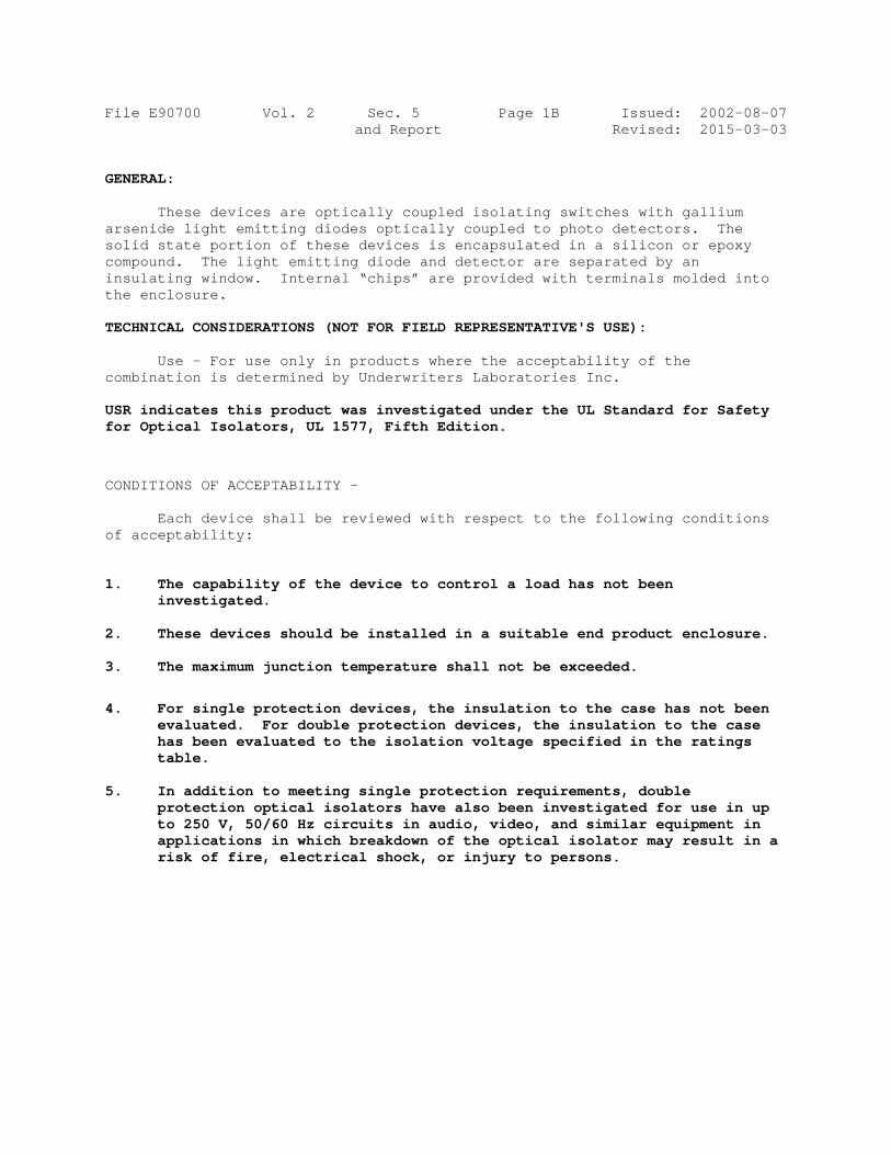
File E90700 Vol. 2 Sec. 5 Page 1B Issued: 2002-08-07 and Report Revised: 2015-03-03 GENERAL:
These devices are optically coupled isolating switches with gallium arsenide light emitting diodes optically coupled to photo detectors. The solid state portion of these devices is encapsulated in a silicon or epoxy compound. The light emitting diode and detector are separated by an insulating window. Internal “chips” are provided with terminals molded into the enclosure. TECHNICAL CONSIDERATIONS (NOT FOR FIELD REPRESENTATIVE'S USE):
Use - For use only in products where the acceptability of the combination is determined by Underwriters Laboratories Inc.
USR indicates this product was investigated under the UL Standard for Safety for Optical Isolators, UL 1577, Fifth Edition.
CONDITIONS OF ACCEPTABILITY –
Each device shall be reviewed with respect to the following conditions of acceptability: 1. The capability of the device to control a load has not been
investigated. 2. These devices should be installed in a suitable end product enclosure. 3. The maximum junction temperature shall not be exceeded.
4. For single protection devices, the insulation to the case has not been
evaluated. For double protection devices, the insulation to the case has been evaluated to the isolation voltage specified in the ratings table.
5. In addition to meeting single protection requirements, double
protection optical isolators have also been investigated for use in up to 250 V, 50/60 Hz circuits in audio, video, and similar equipment in applications in which breakdown of the optical isolator may result in a risk of fire, electrical shock, or injury to persons.

File E90700 Vol. 2 Sec. 5 Page 2 Issued: 2002-08-07 and Report Revised: 2015-03-03
THIS PAGE REPLACES PAGE 2
File E90
CONSTRUC
Geillustradimensio
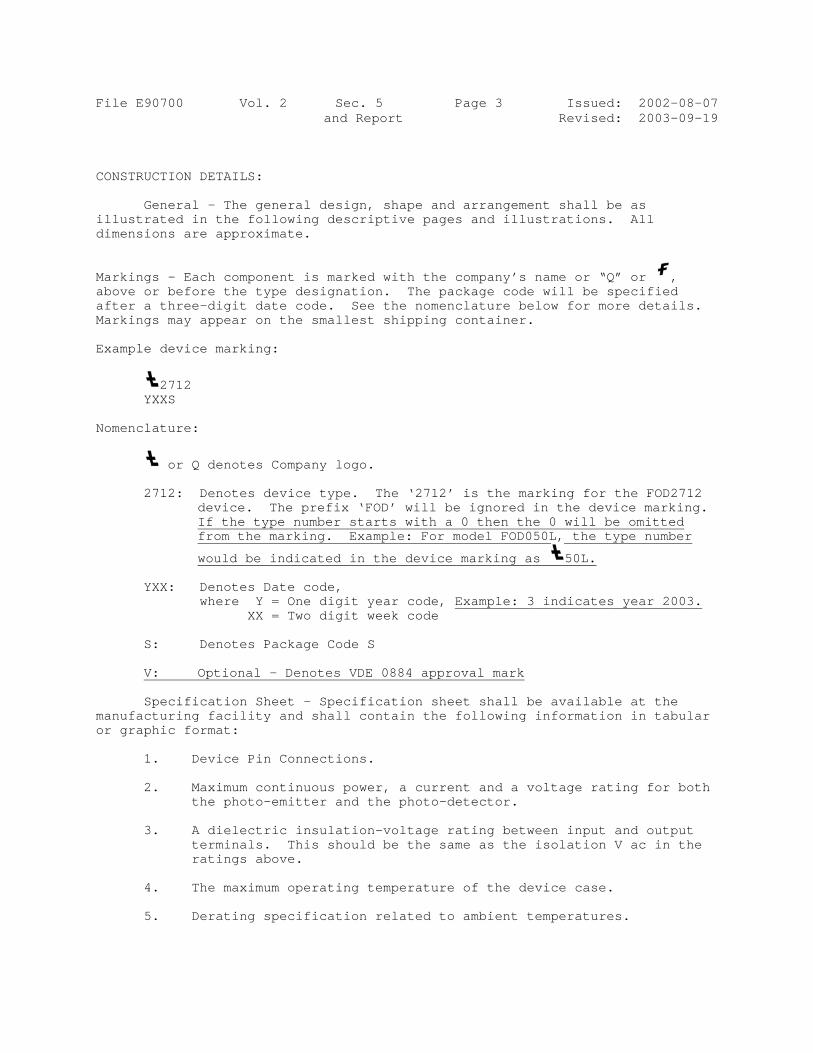
Markingsabove orafter a Markings Example
YX Nomencla
27
YX
S:
V:
Spmanufactor graph
1. 2.
3.
4. 5.
0700
CTION DETA
eneral - Tated in thons are ap
s – Each cr before tthree-digs may appe
device ma
2712 XXS
ature:
or Q den
712: DenodeviIf tfrom
woul
XX: Deno wher
: Deno
: Opti
pecificatituring fachic format
. Devic
. Maximthe p
. A dietermiratin
. The m
. Derat
Vol. 2
AILS:
The generalhe followinpproximate.
component ithe type degit date coear on the
arking:
notes Compa
otes deviceice. The pthe type num the marki
ld be indic
otes Date cre Y = One XX = Two
otes Packag
ional - Den
ion Sheet -cility and t:
ce Pin Conn
mum continuphoto-emitt
electric ininals. Things above.
maximum ope
ting specif
Sec. 5and Repo
l design, ng descrip.
is marked esignationode. See smallest
any logo.
e type. Tprefix ‘FOumber staring. Exam
cated in t
code, e digit yeo digit we
ge Code S
notes VDE
- Specificshall con
nections.
uous powerter and th
nsulation-is should
erating te
fication r
5 Port
shape and ptive pages
with the cn. The pacthe nomencshipping c
The ‘2712’ OD’ will berts with a mple: For m
he device
ear code, Eeek code
0884 appro
cation sheentain the f
r, a currenhe photo-de
-voltage rabe the sam
emperature
related to
Page 3
arrangemes and illu
company’s ckage codeclature becontainer.
is the mae ignored 0 then thmodel FOD0
marking a
Example: 3
oval mark
et shall bfollowing
nt and a vetector.
ating betwme as the
of the de
ambient t
IssuedRevised
ent shall bustrations.
name or “Qe will be selow for mo
arking for in the deve 0 will b50L, the t
s 50L.
3 indicates
be availablinformatio
voltage rat
ween input isolation
evice case.
temperature
d: 2002-0d: 2003-0
be as . All
Q” or , specified ore detail
the FOD27vice markinbe omitted type number
s year 200
le at the on in tabu
ting for b
and outpuV ac in t
.
es.
08-07 09-19
ls.
712 ng.
r
03.
ular
both
ut the

File E90700 Vol. 2 Sec. 5 Page 4 Issued: 2002-08-07 and Report Revised: 2005-06-13
Model Differences - All models have identical insulation systems. The only difference is the lead-frame design or the size of the IC devices.
Abbreviation - R/C = Recognized Component. *
Package Dimensions - See ILL 1 for details.
*

File E90700 Vol. 2 Sec. 5 Page 5 Issued: 2002-08-07 and Report Revised: 2015-03-03 MODEL MOCD2XX - ILL 2 General – ILL 2 shows the wire bonding and coupling diagram and the cross sectional view of Model MOCD2XX. This model represents all models, except where variations are specifically described. 1. Lead Frame – Stainless steel, plated steel, copper, silver, gold,
nickel, aluminum, an alloy of the same, or an equivalent material. 2. Emitter –LED input. 3. Sensor – Bipolar transistor output. 4. Wire - Stainless steel, plated steel, copper, silver, gold, nickel,
aluminum, an alloy of the same, or an equivalent material. 5. Error Amplifier – One provided. Silicon chip. 6. Transparent Coat (Dome) - Dow Corning, Type Hipec Q3-6633. Min. 0.5 mm
through insulation. 7. Enclosure - Epoxy, Vyncolit North America, Type E8436FR or E8436 FR-
397. Epoxy, molded without air pockets.
Alternate - Same as above, except R/C (QMFZ2), Kyocera Chemical, Type KE-96A.
MODEL FOD27X2Y
General – This model also represents model MOC2XX. Same as Model MOCD2XX, except as specifically described below. 1. Lead Frame –Stainless steel, plated steel, copper, silver, gold,
nickel, aluminum, an alloy of the same, or an equivalent material. See ILL 3 for details.6. Transparent Coat (Dome) - Dow Corning, Type Hipec Q3-6633. Min. 0.4 mm through insulation.
Model FOD050L General – This model also represents models FOD070L, HCPL-0453. Same
as model MOCD2XX, except as specifically described below. 1. Lead Frame – Stainless steel, plated steel, copper, silver, gold,
nickel, aluminum, an alloy of the same, or an equivalent material. See ILL 5 for details.
File E90700 Vol. 2 Sec. 5 Page 6 Issued: 2002-08-07 and Report Revised: 2015-03-03 Model FOD053L General – This model also represents models FOD073L, HCPL-0530, HCPL-
0531, HCPL-0534, HCPL-0730, HCPL-0731. Same as model MOCD2XX, except as specifically described below.
1. Lead Frame - Stainless steel, plated steel, copper, silver, gold,
nickel, aluminum, an alloy of the same, or an equivalent material. See ILL 6 for details.
Model HCPL0611 General – Same as model MOCD2XX except as noted below. This model also represents models FOD060L. 1. Lead Frame – Stainless steel, plated steel, copper, silver, gold,
nickel, aluminum, an alloy of the same, or an equivalent material. See ILL 5 for details.
6. Transparent Coat (Dome) - Dow Corning, Type Hipec Q3-6633. Min. 0.4 mm through insulation.
File E90700 Vol. 2 Sec. 5 Page 7 Issued: 2002-08-07 and Report Revised: 2014-05-27 * Model FOD0710 * General – Same as model MOCD2XX except as noted below. This model also represents models FOD0720, FOD072L, FOD0721 and FOD8001.
1. Lead Frame – Stainless steel, plated steel, copper, silver, gold,
nickel, aluminum, an alloy of the same, or an equivalent material. Isolation gap between Emitter (LED) and Detector (FET) is 0.5 mm minimum. See ILL 7 for details.
2. Emitter – LED input. 3. Detector – FET output. 4. Dome –Type HIPEC Q3-6633 by Dow Corning. 5. Enclosure – Type KE-96A by Kyocera Chemical Corp. 6. Wire – Stainless steel, plated steel, copper, silver, gold, nickel,
aluminum, an alloy of the same, or an equivalent material. 7. Driver – Silicon driver chip.

File E90700 Vol. 2 Sec. 5 Page 8 Issued: 2002-08-07 and Report New: 2010-08-13 Model FOD8012 1. Emitter – LED input. 2. Detector – FET Output. 3. Lead Frame – Metal employed for current carrying parts shall be of
stainless steel, silver, gold, copper, nickel, aluminum, an alloy of the same, or an equivalent material.
4. Bond Wire – Metal employed for current carrying parts shall be of
stainless steel, silver, gold, copper, nickel, aluminum, an alloy of the same, or an equivalent material.
5. Case (Outermold) – Epoxy molded resin, type KE-96A5 by Kyocera Chemical
Corp. Molded using high temperature and high pressure process. 6. Window (Dome) - Epoxy molded resin, Type HIPEC Q3-6633 by Dow Corning.
Minimum 0.47 mm through insulation spacing between the input and the output circuits. Molded using a high temperature and high pressure process.