Embed Size (px)
Citation preview

MA234-5: Build the Foundation: Autodesk® Inventor
®
Drawing Templates
Mark Flayler – IMAGINiT Technologies
MA234-5 The Autodesk Inventor Drawing Manager is used to create critical documentation for the
digital prototyping process. After you create a model, you can produce a drawing to document your design. In the drawing, you can place views of a model on one or more drawing sheets. You can then add dimensions and other drawing annotations to document the model. Using a powerful template at the beginning of the documentation process can increase productivity by eliminating redundancy and keeping the team on a set of company-enforced standards. This class is designed for users wanting to get more out of their drawing templates and a better understanding of the resources that go into a potent documentation engine.
About the Speaker: Mark has been using Autodesk® products since 1999 in many different manufacturing environments. He has implemented Autodesk products for many diverse industries. Autodesk® Inventor® has profoundly augmented Mark's abilities, allowing him to bring 3D digital prototyping to the forefront of the industries with which he has interacted. Mark has extensive experience and a comprehensive understanding of the technical and practical business and human dimensions of implementation. His expertise has helped his clients to maximize their project's effectiveness and return on investment. He is an effective and skillful communicator, consulting with his clients to help them achieve their business objectives. Mark provides training, support, and implementation on all Autodesk manufacturing solutions.
Blog: http://blogs.rand.com/manufacturing/

Build the Foundation: Autodesk® Inventor
® Drawing Templates
Introduction
Each new drawing is created from a template. When you install Autodesk Inventor, your selection of a
default drafting standard sets the default template that is used to create drawings for modeling files. The
creation of a company template to meet standards is critical to any implementation of Autodesk Inventor.
A company template can contain custom resources for industry and company documentation procedures.
In this class we will look at these creation tools and their not hidden pitfalls and go over some decisions
for creating a template that is right for you and your company.
Before we begin a few words on documentation...
As we go through the settings and procedural enlightenment in this course, make sure you document the
changes and settings that are taking place for use at your company. You do not have to record every
style setting, but make sure you can convey how your template is intended to be used in practice. At the
end of your template creation process or during it, make notes and take screen grabs to show users how
the data is mapped and how the Drawing Resources are to be used. This will help when the template is
being adopted by current and new employees and will be a reminder of when or if you need to revise the
drawing templates.

Build the Foundation: Autodesk® Inventor
® Drawing Templates
3
Procedural Consideration
A large part of any template creation process is the incorporation of company
principles into the design intent of the file. The following are some questions that you
can ask yourself as you create your first Inventor Drawing Template file. These
questions may seem mundane to most single users, but sometimes the driving
factors of detailing and file tracking are determined by company data management
systems, and those systems are not always the friendly neighborhood Vault product.
Other reasons for detracting from the norm are industry/company standards that do
not follow a specific engineering standard or majority convention.
If you have already been producing drawings for some time you should already know the answers to
following questions. However, if you are new to Inventor or trying to fine tune your design documentation,
you should take the time to ask yourself some of these sample questions:
How do you produce the documentation of your designs?
o One detail print file per modeling file.
o One detail print file per IAM that would include the part details.
o Dealer’s choice based on the particular assembly.
Where do you want your design tracking properties to be stored?
o In the modeling files.
o In the detail prints.
o In both.
How do you handle multiple sheets?
o As separate detailing files.
o Inclusive to the single detailing file.
Where does your control for the styles resolve?
o In the Administrative Styles Library?
o In the drawing template?
Which sheet sizes do you typically use?
o ANSI, do you only use B and D?
o ISO, do you only use A4?
o Of the two above, which size is the most commonly used?
Do you use Vault or data management software similar to Vault?
o Yes, we do.
o No, but we might in the future.
o Never, data management is overrated.
What information is to be in the Title Block?
Which industry standard symbols or notations need to be added?
What information is to be in the Border?
While I cannot wave a magic wand and create a template and a process that works for everyone, the
tools in this course will show you different methods of resolving your questions, which tools to avoid in
certain situations, and how to work with Inventor to do something not inherit to its native coding.

Build the Foundation: Autodesk® Inventor
® Drawing Templates
4
Should I Use DWG or IDW?
Beginning in Inventor 2008, Autodesk reintroduced the DWG format to the Inventor kernel after a very
long hiatus. This was designed to open many collaborative doors for Inventor alongside a supportive
AutoCAD, enabling companies to work internally as well as externally. At that point, for all intents and
purposes Autodesk left the IDW format alone for the sake of legacy.
IDW and DWG are identical in Inventor functionality with a few minor differences:
Inventor DWG files can be opened directly in AutoCAD 2007 and up (previous versions require a
free Object Enabler available at Autodesk.com). Once opened in AutoCAD, you can measure,
print, or even detail the Inventor geometry.
o Once opened in AutoCAD, the Inventor views are blocks that cannot be exploded.
o Jogged and broken views do not measure correctly in AutoCAD due to the parametric
nature of the views in Inventor.
Inventor DWG views are searchable in AutoCAD DesignCenter for factory floor layouts as block
views. Therefore, any views created in an Inventor DWG can be reused without exporting and
copying.
Inventor IDWs cannot use AutoCAD created blocks for symbols or notations in Inventor
documentation. However, the Inventor DWG can import and place them.
Inventor DWGs are inherently larger in size due to the advantages above.
Inventor DWGs can aid in 2D to 3D migration by updating or creating parts/assemblies inside
Inventor and then adding them to the existing 2D assembly or layout.
Use a client’s AutoCAD DWG as a starting point to obtain their standards and styles.
Note: Remember that just because you can open an Inventor DWG in AutoCAD, it does not mean you
can change the modeling geometry. This is similar to using a mechanical structure in AutoCAD
Mechanical. The originating software must make the edits using the original modeling files. This is to
prevent improper design tracking when collaborating on designs internally and externally.
If you stay with IDW or use it from the beginning, it is probably for one of the following reasons:
You have always used IDWs and see no reason to collaborate your data and change your file
format.
You choose to keep your Inventor files completely separate from your AutoCAD drawings due to
file format confusion internally or poor tracking policies.
If you fall into one of these categories, I would urge you
to reevaluate your decision as IDW files might disappear
in the future and more functionality might be added to the
DWG format instead. Getting behind the technology
early is better than trying to catch up to it later. If needed
there is a batch translation tool in the Task Scheduler to
turn Inventor IDWs into Inventor DWGs.

Build the Foundation: Autodesk® Inventor
® Drawing Templates
5
iProperties vs. Prompted Entries
Let’s take a deeper look at the differences in iProperties and Prompted Entries. There are pros and cons
to both methods of tracking design information but after looking at differences, the segregation of the two
input tools becomes clear. If this is not understood correctly, you might find yourself down the wrong path
when your business software changes. Let’s look at the equivalent tools in AutoCAD.
Inventor iProperties are equivalent to AutoCAD Drawing Properties (DWGPROPS)
Inventor Prompted Entries are equivalent to AutoCAD Block Attributes (ATTDEF)
Based on this precursory knowledge that a lot of transitioning users have about AutoCAD they almost
immediately start creating Prompted Entries for the Title Block since it is a similar method to how things
are done by the majority of AutoCAD users.
It seems to be a very well kept secret in AutoCAD that DWGPROPS and the use of FIELDS are the best
way to populate a Title Block in AutoCAD. When companies find out about this method of Title Block
population, it is usually too late as they might already have created a large number of legacy drawings
using attributed blocks. This usually becomes apparent when companies start looking at data
management solutions. Some of these programs have a VERY hard time working with attributed blocks.
Autodesk Vault is perhaps the most skilled at this, but it is not always the system of choice for a large
company.
When data management systems index metadata of files they inherently can read the Properties of a file
whether it is Word, Adobe, Inventor, or AutoCAD. This makes searching for any data in the data
management system very easy to do and greatly speeds up the design process by circumventing the
opening of a large amount of files to find the correct one. In order to have this functionality you must
use iProperties in your template. Prompted Entries will not be searchable.
Moreover they can control the same information across multiple layout sheets so if the information is the
same in 7 layouts then the user does not have to change the attributed Title Block 7 times but only
change it in the DWGPROPS once. This will work the same way in Inventor across multiple sheets in a
drawing as well compared to inputting the same information in prompted entries over and over again.

Build the Foundation: Autodesk® Inventor
® Drawing Templates
6
Anatomy of an Inventor Drawing Template
Let’s make sure we are on the same page shall we, or is it the same sheet? In an Inventor drawing,
whether it is an IDW or DWG, there is a drawing browser bar on the left side of the screen. The Sheet
node in the browser will contain your drawing views, sketches, sheets, and anything you put on your
sheet. There is also the Drawing Resources node, which contains the important information for this
course. Inside Drawing Resources you will find Sheet Formats, Borders, Title Blocks, and Sketched
Symbols. If it is a DWG file you will also see AutoCAD Blocks.
Each Sheet consists of one Title Block, one Border, and as many Sketched Symbols or AutoCAD
Blocks as needed. These combined resources can then be turned into a Sheet Format for quick sheet
creation. In the default template included with Inventor, there are six Sheet Formats consisting of the
Default Border and one of the two default Title Blocks. I have never met a user of the software that only
used these defaults, unless they were in an educational system without proper administrative support.
A lot of people will say, why not just import an AutoCAD block or use an existing AutoCAD DWG for the
Inventor template? Why go through this process of creating a unique template? Well, there are good
reasons for creating a native Inventor template file, which we will discuss during the class.
Sometimes, creating an Inventor template from an AutoCAD DWG is acceptable, such as when new
client styles and standards are given to a design shop and the shop must adhere to those standards.
On the other hand, some items do not transfer 1 to 1 when imported into Inventor. Creating a native
template solves these issues and allows users to experience all of Inventor’s Styles and Standards
settings.

Build the Foundation: Autodesk® Inventor
® Drawing Templates
7
Creation of Drawing Resources
The creation of Drawing Resources, such as Title Blocks, Sheet Formats, Borders, and Sketched
Symbols is imperative to the proper setup of a template. Having a uniform look and feel for the layout and
usage of these resources is the essence of a company or industry standard. While there is not a specified
order in which to create these elements, the following is a recommended workflow:.
Start a blank drawing
Set the sheet size.
Set up local styles
Create a Border resource.
Create a Title Block.
Create any Sketched Symbols or Blocks.
Create a Sheet Format.
Double-check your intent.
Styles Library administration.
Set your template to default opening settings.
Save the Template in the template directory.
Start a Blank Drawing
To begin creating a new template from scratch with no drawing resources in it (no Title Blocks, Sheet
Formats, Sketched Symbols, Blocks, and only the default Border), hold down CTRL and SHIFT and
select the new drawing button in the Quick Access Toolbar.
Set the Sheet Size
Set your default Sheet Size by right-clicking on
Sheet: 1. Select a size that is most commonly
used by your company (B and D are perhaps the
most common).
Exclude from count and Exclude from
Printing are important if you use Title Pages
that contain reference information or other
information not necessary to the printable set.
Build the Foundation: Autodesk® Inventor
® Drawing Templates
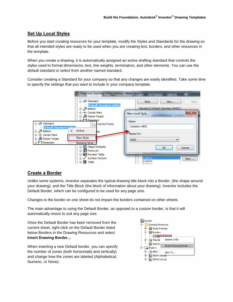
Set Up Local Styles
Before you start creating resources for your template, modify the Styles and Standards for the drawing so
that all intended styles are ready to be used when you are creating text, borders, and other resources in
the template.
When you create a drawing, it is automatically assigned an active drafting standard that controls the
styles used to format dimensions, text, line weights, terminators, and other elements. You can use the
default standard or select from another named standard.
Consider creating a Standard for your company so that any changes are easily identified. Take some time
to specify the settings that you want to include in your company template.
Create a Border
Unlike some systems, Inventor separates the typical drawing title block into a Border, (the shape around
your drawing), and the Title Block (the block of information about your drawing). Inventor includes the
Default Border, which can be configured to be used for any page size.
Changes to the border on one sheet do not impact the borders contained on other sheets.
The main advantage to using the Default Border, as opposed to a custom border, is that it will
automatically resize to suit any page size.
Once the Default Border has been removed from the
current sheet, right-click on the Default Border listed
below Borders in the Drawing Resources and select
Insert Drawing Border...
When inserting a new Default border, you can specify
the number of zones (both horizontally and vertically)
and change how the zones are labeled (Alphabetical,
Numeric, or None).

Build the Foundation: Autodesk® Inventor
® Drawing Templates
9
Setting the number of zones to 0 will remove the
zone marking from the inserted border.
Click the >> button to expand the dialog box and
display the additional options.
In the expanded dialog box, use the options to
specify the text style and layer to use for the border
text and adjust the location from which the zones
are labeled. This is an example of why you should
create custom Text Styles before implementing any
Drawing Resource creation so that the correct style
can be selected.
Additionally, toggle off Center Marks if they are not
required and adjust the Sheet Margins (the offset
of the border geometry from the outside edge of the
paper).
Create a Title Block
Main Title Block
It would be wise to determine size and spacing before starting this procedure. Print a copy of the Border
without the Title Block and sketch a rough idea of what you want to have in your Title Block by hand. You
might want to use a legacy AutoCAD Title Block as a starting point.

Build the Foundation: Autodesk® Inventor
® Drawing Templates
10
If you want to use an existing AutoCAD Title Block in Inventor, you can import one, but it will place all of
the attribute definitions as prompted entries and will not be indexable in Data Management software. If
the AutoCAD Title Block was created correctly, using Fields rather than Attributes, they would import as
Custom iProperties and would be searchable but not necessarily mapped correctly. In addition, not
everything will be scaled correctly when imported from AutoCAD into Inventor. It will be close, but not
close enough for me. For this reason, I usually start from scratch when creating Title Blocks.
To create a new Title Block Definition, right-click on the Title Block area of the Drawing Resources and
select Define New Title Block. You will be placed into a Sketching environment, similar to but not equal
to the ones found in Part and Assembly modes (see the Drawing Resource Construction Tools at the end
of this handout).
Start by sketching out a rough shape and size for your Title Block. Use dimensions where necessary and
even dimension expressions are available here. Try to avoid too many dimensions or constraints as we
all know that too much of either can slow Inventor down and in the drawing environment has been known
to cause errors if equations are overused. I tend to use construction geometry a lot here to avoid this.

Build the Foundation: Autodesk® Inventor
® Drawing Templates
11
Text can be used in a drawing resource to create standard notations and report on company design tracking properties. When using text in a drawing resource, use the Type selection box to select the required category and the Property selection box to select the required property.
Note: Use the Add Text Parameter button ( ) to add values to the text.
Option Description
Properties - Model iProperty values from a given model reference.
Properties - Drawing iProperty values from the drawing file.
Custom Properties - Drawing
Custom iProperty value from the drawing file.
Custom Properties - Model
Custom iProperty value from a given model reference. (You might have to insert a model to get this in a template and then delete the View.)
Drawing Properties Property: Number of Sheets
Sheet Properties Properties: Sheet Number, Sheet Revision, and Sheet Size
Prompted Entries Creates Custom in place user entries (similar to ACAD attributes).
_Piping Style Properties associated with the Routed Systems package.
Physical Properties - Model
Properties: Area, Density, Mass, and Volume. (Hint: make sure the Application Setting is Update Mass Properties on Save.)
Sheet Metal Properties
Properties: Flat Pattern Extents Area, Flat Pattern Extents Length, and Flat Pattern Extents Width.
Property Selections
The Prompted Entries category allows you to create custom user-defined text and prompts for users.
Select Prompted Entry and enter the required question or information from the designer in the
highlighted area.
Note: Only one Prompted Entry is allowed per Text Box.
Types of Properties (insertion of a source file may be required to
obtain specific Type Properties)

Build the Foundation: Autodesk® Inventor
® Drawing Templates
12
When using text, make sure you use the correct justifications, line spacing, single or multi-line options,
colors, text overrides, and any predefined text styles that you previously created.
Use Horizontal and Vertical constraints with the text objects and their justifications to align them in
addition to dimensional relationships (these can be done but not edited by a Parameters box).
Note: You might have to finish the sketch and validate the work to make sure you are leaving enough
space for the designated values (placement and quantity of text).
Eventually this:
Will become this:
Multiple Title Block
Commonly, it is necessary to create multiple sheets so that more extensive data can be recorded. It is not
usually necessary to repeat all of the information contained in the Main Title Block in subsequent sheets.
This creates more room for detail work and reduces the amount of repetitive information across the
drawing package. While this is a company’s prerogative, there are long standing roots in industry and
standards to simplify the multiple sheets in a drawing.
Repeat the procedures for creating a main Title Block, but apply less information in order to follow this
documentation method.

Build the Foundation: Autodesk® Inventor
® Drawing Templates
13
Company Logo: Bitmap or Redraw?
When choosing a placement method for a Company Logo in a Title Block, there are a few things to watch
out for. These are small things that can cause great annoyance if not foreseen. The image below shows a
Bitmap and a Sketched Company Logo. I’ll leave it to you to decide which one is which.
When a Bitmap is placed in any file using the Insert Image
command, you can either Link or Embed the image. Linking will
always force Inventor to look for a location for the image outside
the file, based on your project workspace. In companies in which
project files are not used correctly, it is prone to losing the
reference.
To embed the file instead of linking it, clear the checkbox when
first placing the image. Another disadvantage of an image,
whether it is linked or embedded, is that it normally creates
extra bitmaps when files are exported to AutoCAD.
In the end, to avoid these issues, redrawing the image from
scratch or inserting an older AutoCAD rendition is best.
Title Block Insertion
The Application Options or sheet overrides are used to control the insertion of the Title Block. The overall
geometry controls the placement into the border. The extents of the geometry will determine the block
placement, and the outermost entity thereof will be used as the insertion point. Therefore, if you have a
lingering point in your definition outside your design area, it will become the point at which the definition
will be inserted.
Title Block Insertion Setting No! Yes!
Create Sketched Symbols or Blocks
See last year’s class at AU2009, which focused solely on Sketched Symbols and AutoCAD Blocks.
Class ID: MA314-1: It’s Not Sign Language.

Build the Foundation: Autodesk® Inventor
® Drawing Templates
14
Its Not Sign Language goes further in depth on this topic than is permitted by the time available for this
session. It also details how to use the Inventor Sketcher inside the Drawing Manager of Inventor. Since
there are some key differences between Drawing and Part sketching.
Make sure you capture your company’s industry or private symbols in this form to use throughout the
Drawing Manager. This will avoid having to do heavy reproduction and copy and paste operations
between files. If there are a large number of symbols, you can organize them into folders within the
Drawing Resources folder as well.
Create a Sheet Format
Once a Sheet has been created with proper sizing for the layout, and proper Borders, Title Block, and
default Sketched Symbols have been placed, you can create a saved Sheet Format from the current set
up. If required, you can also add a default set of views to the sheet and have Inventor prompt for a part or
assembly file when the sheet is activated. Although this is a designed method, it seldom works perfectly
and the majority of Inventor users would rather place the views manually themselves to convey their
intended design.
To create a basic Sheet Format without views right-click on the Sheet header in the Drawing Manager
and select the Create a Sheet Format option. Name the Format per the decisions made during its
creation, such as B-Sized Main or B-Sized Multiple sheet.
Double-check your intent
Always double-check your intent for the template before it is saved. Ideally include the entire Inventor
team in the decision making process so that everyone understands what went into the template so that if
changes need to be made after initial inception that the user base will understand how to ask, and what
not to ask for.
Build the Foundation: Autodesk® Inventor
® Drawing Templates
15
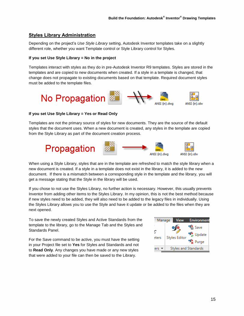
Styles Library Administration
Depending on the project’s Use Style Library setting, Autodesk Inventor templates take on a slightly
different role, whether you want Template control or Style Library control for Styles.
If you set Use Style Library = No in the project
Templates interact with styles as they do in pre-Autodesk Inventor R9 templates. Styles are stored in the
templates and are copied to new documents when created. If a style in a template is changed, that
change does not propagate to existing documents based on that template. Required document styles
must be added to the template files.
If you set Use Style Library = Yes or Read Only
Templates are not the primary source of styles for new documents. They are the source of the default
styles that the document uses. When a new document is created, any styles in the template are copied
from the Style Library as part of the document creation process.
When using a Style Library, styles that are in the template are refreshed to match the style library when a
new document is created. If a style in a template does not exist in the library, it is added to the new
document. If there is a mismatch between a corresponding style in the template and the library, you will
get a message stating that the Style in the library will be used.
If you chose to not use the Styles Library, no further action is necessary. However, this usually prevents
Inventor from adding other items to the Styles Library. In my opinion, this is not the best method because
if new styles need to be added, they will also need to be added to the legacy files in individually. Using
the Styles Library allows you to use the Style and have it update or be added to the files when they are
next opened.
To save the newly created Styles and Active Standards from the
template to the library, go to the Manage Tab and the Styles and
Standards Panel.
For the Save command to be active, you must have the setting
in your Project file set to Yes for Styles and Standards and not
to Read Only. Any changes you have made or any new styles
that were added to your file can then be saved to the Library.

Build the Foundation: Autodesk® Inventor
® Drawing Templates
16
If this is not done, every time the template is started with the settings set to Yes or Read Only, an error
message opens prompting you that some styles do not match. It also prompts you that it will use the
default styles in the Library rather than the modified ones. This is another great reason why the template
should contain all new styles for your company, rather than a modification of the default ones.
Set your template to the default opening settings
Make sure your template is designed for the most likely Sheet Format and Active Standard , so that when
a new document is created from it, these will be used by default. When it is saved and then loaded as a
template, it will take the last settings from file to start with. This is a simple step, but unless mentioned it
is easily forgotten.
Build the Foundation: Autodesk® Inventor
® Drawing Templates
17
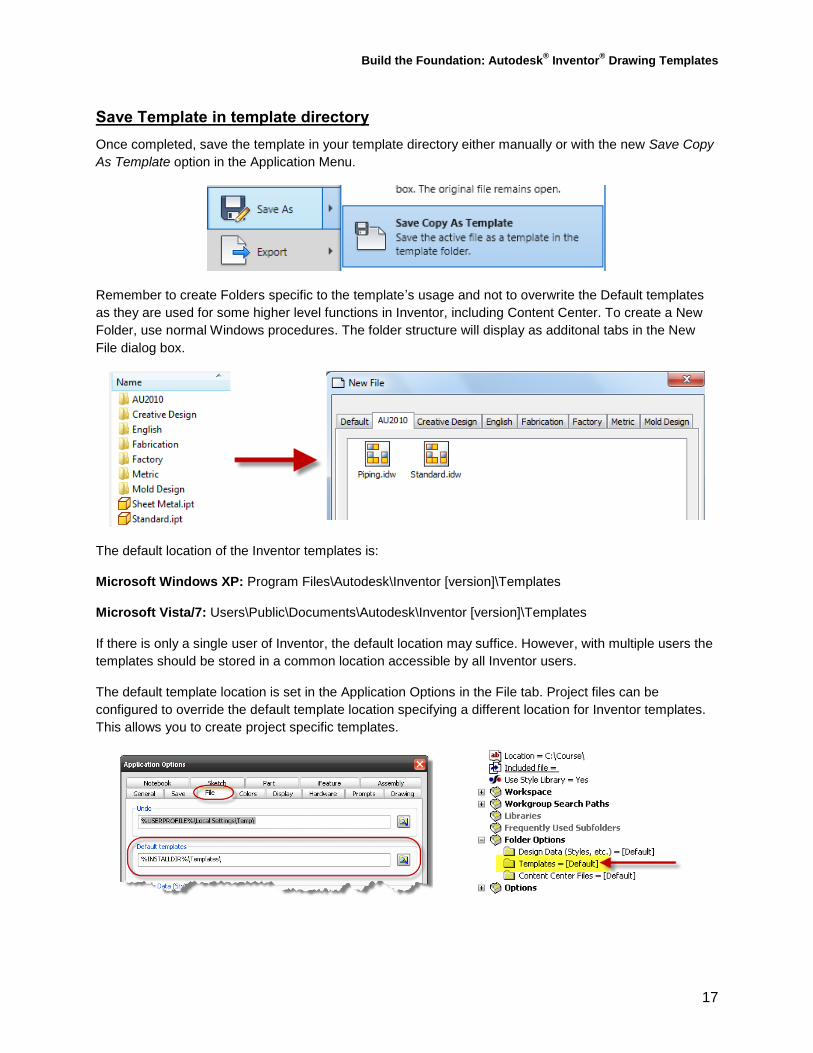
Save Template in template directory
Once completed, save the template in your template directory either manually or with the new Save Copy
As Template option in the Application Menu.
Remember to create Folders specific to the template’s usage and not to overwrite the Default templates
as they are used for some higher level functions in Inventor, including Content Center. To create a New
Folder, use normal Windows procedures. The folder structure will display as additonal tabs in the New
File dialog box.
The default location of the Inventor templates is:
Microsoft Windows XP: Program Files\Autodesk\Inventor [version]\Templates
Microsoft Vista/7: Users\Public\Documents\Autodesk\Inventor [version]\Templates
If there is only a single user of Inventor, the default location may suffice. However, with multiple users the
templates should be stored in a common location accessible by all Inventor users.
The default template location is set in the Application Options in the File tab. Project files can be
configured to override the default template location specifying a different location for Inventor templates.
This allows you to create project specific templates.

Build the Foundation: Autodesk® Inventor
® Drawing Templates
18
iLogic
Certain tasks that Autodesk has not built into the drawing environment can be programmed based on
your company’s policies. Essentially telling Inventor how to work instead of intelligently tricking Inventor
to work the way your company documents. Make sure you understand the difference between controlling
your rules externally or internally to a file. In the examples below the rules are all saved locally to the
template before it is saved so that every file created with the template has this rule to drive the logic.
One use for iLogic is to make sure iProperties are filled in whether they are Custom or Standard as shown below…
Title iProperty Example:
Title = iProperties.Value("Summary", "Title")
If Title = "" Then
Title = InputBox("Please Enter the iProperty Title", "iProperties
Check - Title Filled Out?", Description)
iProperties.Value("Summary", "Title") = Title
End If
Part Number iProperty Example:
PartNumber = iProperties.Value("Project", "Part Number")
If PartNumber = "" Or PartNumber =
ThisDoc.FileName'(False) 'without extension
PartNumber = InputBox("Please Enter the iProperty Part
Number", "iProperties Check - Part Number", PartNumber)
iProperties.Value("Project", "Part Number")= PartNumber
End If
An important note about iLogic is how rules are triggered; the above rules are controlled by the Event Trigger to run Before Save Document.
List of Drawing and iProperty
Snippets

Build the Foundation: Autodesk® Inventor
® Drawing Templates
19
Update Drawing iProperties based on Model iProperties (Standard or Custom)
This code snippet has the functionality to update the drawing iProperties with the Model iProperties info.
Usually this isn’t a big concern since Title Blocks and other properties can be placed into the drawing.
The problem with this method is when you are indexing iProperties in Vault and need to search to find
files with certain values, the Assembly or Part will show up but not the Drawing. This snippet will take
care of that so searches on iProperties will return both results. Also note that this only works well with a
one model file / one drawing file documentation approach.
If (ThisDrawing.ModelDocument Is Nothing) Then Return
modelName = IO.Path.GetFileName(ThisDrawing.ModelDocument.FullFileName)
iProperties.Value("Custom", "Property1Name") = iProperties.Value(modelName,
"Custom", "Property1Name")
iProperties.Value("Custom", "Property2Name") = iProperties.Value(modelName,
"Custom", "Property2Name")
Place 1st
View Scale Based into Custom iProperty for Title Block Scale Value Use this to place the scale string value shown in your 1
st Base View dialog box to a custom property (in
this case it must already be created), that is used in your Title Block. This way you don’t have to baby sit the value for the scale as it will update before saves with the Rule Triggers.
iProperties.Value("Custom", "1st View Scale") =
ActiveSheet.View("VIEW1").ScaleString

Build the Foundation: Autodesk® Inventor
® Drawing Templates
20
Drawing Resource Transfer Wizard
If a Drawing Resource needs to be populated through multiple drawings it would be rather tedious and
inefficient to manually copy and paste the updated symbol. This is where the Drawing Resource Transfer
Wizard (DRTW) is used. This wizard can batch process the addition or replacement of Borders, Title
Blocks, and in our case Sketched Symbols to multiple existing files.
Note: DRTW does not work on AutoCAD blocks or Sheet Formats.
The DRTW has to be launched externally to Inventor while the Inventor application is closed. When
initialized, the program runs Inventor in the background to process the intended operations. The utility can
be found in the Start Menu.
As a rule of thumb, start with a good source file that contains everything you need to transfer to the
destination files. This is usually a drawing template that has been updated with the new or updated
symbols. Here is a breakdown of the steps in the dialog boxes:
1. Select the Resources to transfer.
Choose your source file and check the resources to transfer to the target files.
2. Select the Target Files.
These can be IDW or DWG and you can use <Shift> or <Ctrl> to select multiple files.
3. Same name replacement/ignoring symbols.
If updating symbols, some data loss is possible if the prompted text fields do not match.
4. Start and view the process.
A progress bar will display and a log file will be processed.
5. Review the log file for error checking.
Check for any missed or unable to update target drawings.
Class Summary: The creation of Drawing Templates and the utilization of Styles and
Standards increases the conformity of the documentation process. The various tools and
methods allow for a flexible drawing environment that will meet your company’s needs now and
as standards change throughout the years. Mapping correct data from either the model or drawing
and using Autodesk Vault for indexing these values can greatly speed up searching for data in a
large file store. By using these templates inside Inventor’s Drawing Manager, companies
ultimately save time and reduce errors in product life cycles and reduce time spent constantly
modifying the same styles as well as having to recreate or manage multiple sheets and formats.

Build the Foundation: Autodesk® Inventor
® Drawing Templates
21
Appendix: Drawing Resource Construction Tools
How many times have you found yourself drawing the same entities for a symbol? Can you do it with your
eyes closed? This class aims to teach you how to reduce repetitiveness in your design documentation
using user created custom symbols in Inventor and from legacy AutoCAD drawings. Using these tools is
excellent for productivity, standardization, and conformity.
Sketching Tools for Drawing Resources
The sketching environment that is activated is slightly different to that found in the modeling environment.
For example, the Manage tab does not contain Parameters for sketched dimensions even though
dimensional relationships can still be made. The highlighted commands below show some of the
important commands that are used when creating sketched symbols.
The Sketch Only command in the Format panel
allows creation of geometry to be toggled for
visibility in the symbol once the definition has been
created.
This geometry toggle is similar to the Construction
toggle ( ) in the normal modeling sketch
environment.
NOTE: Dimensions are always Sketch Only.
Constraints and Dimensions
The use of Geometric Constrains and Dimensions does not differ from normal Inventor sketch usage, with
the exception of dimensional relations that are not tracked in the Parameters Manager. To improve
performance in large Title Block sketches, consider using dimensions and constraints along with correctly
justified text to create a professional border. Simply eyeballing it does not really work.

Build the Foundation: Autodesk® Inventor
® Drawing Templates
22
The Fill/Hatch Region command hatches an enclosed boundary with a pattern or a solid fill color.
Sometimes, when the command cannot distinguish which boundary to hatch or fill, a may be
required to break up some boundary lines. When the command is invoked it will only show the hatches
available in the current Standard. In this case, only ANSI 31 - 38 appears in my list and ANSI 31 is the
default. In Inventor 2011, you can add custom .PAT files from AutoCAD as well.
Once the Fill/Hatch Region command is
started, select a single boundary. If the
boundary is valid it will highlight as
sketched.
Selecting the boundary opens the dialog box
to enable Hatch or Color Fill and their
options. This only works for one boundary at
a time so repeat as needed.

Build the Foundation: Autodesk® Inventor
® Drawing Templates
23
Related Classes
Styles and Standards Management:
Class ID: CM422-1 – AU2010
Speaker: Stan Wile, MSD Sr. Application Engineer
Class Description:
This class will discuss and demonstrate how to properly configure and use the Design Data
folder. We will dive into the folder and review its inner workings. This will take you through Tube
and Pipe styles, Hole and Thread data, Sheet Metal styles, Studio Lights and Scenes, as well
as each tab of the Styles and Standards dialog box for parts and drawings. Proper migration of
the Design Data folder for future releases will be discussed as well.
Learning Objectives:
Understand the benefit shared styles and standards
Fully understand how to setup, configure, and use the styles and standards
Learn about some little known settings hidden in the Design Data folder
Understand how to setup Inventor to better work for you
Modify your templates to meet your own company standards
Sketched Symbol Creation and Drawing Sketch Tools:
Class ID: MA314-1 – AU2009
Speaker: Mark Flayler, MSD Application Engineer
Class Description:
Drawing Manager in Autodesk Inventor has the functionality to create Custom Sketched
Symbols to document your designs or standardize your company's notations and standards
without the monotony of recreation. This class takes a look at the tools available in the Drawing
Manager that are designed to facilitate this need. Learn to create and use custom notations and
geometry to communicate your design. Use blocks from your AutoCAD® drawings for similar
usage with little redesign for use in Inventor. Learn how to organize and update your symbol
libraries using Inventor's Drawing Resource Transfer Wizard.
Learning Objectives:
Learn to create custom sketched symbols in the Drawing Manager
Use existing blocks from AutoCAD files in Inventor drawings
Learn how to use prompted entries, iProperties, and connection points effectively
Identify Design Intent usage in your drawings
Learn how to update and replace symbols across multiple drawing files