Embed Size (px)
Citation preview
1
CISCO WAN MANAGER
INGRESAR AL GESTOR Pag 2 LISTAR UNA CONEXIÓN Pag 4
ELINIMAR UNA CONEXIÓN Pag 5
CONFIGURACIÓN DE LOGICAL PORT ACCESO AL EQUIPO Pag 6
CREAR UN LOGICAL PORT Pag 7 ELINIMAR UN LOGICAL PORT Pag 8 CREAR CONEXIÓN FR - ATM Pag 9 CREAR CONEXIÓN ATM – ATM Pag14
2
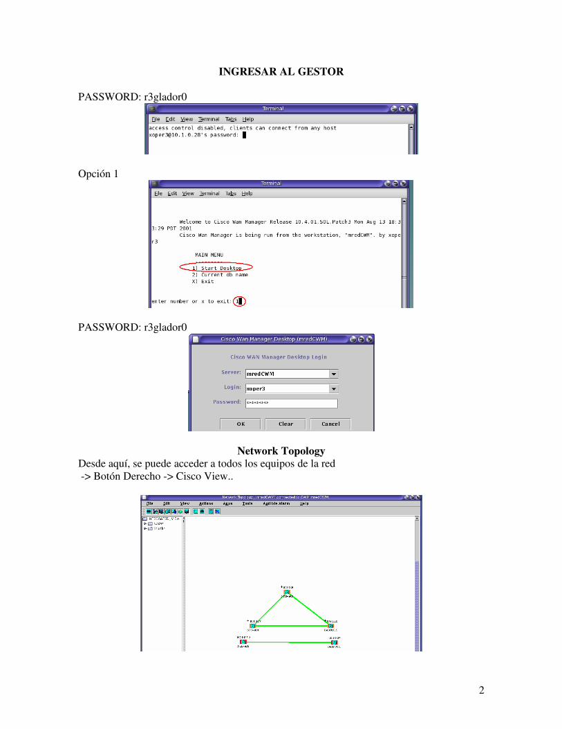
INGRESAR AL GESTOR
PASSWORD: r3glador0
Opción 1
PASSWORD: r3glador0
Network Topology Desde aquí, se puede acceder a todos los equipos de la red
-> Botón Derecho -> Cisco View..
3
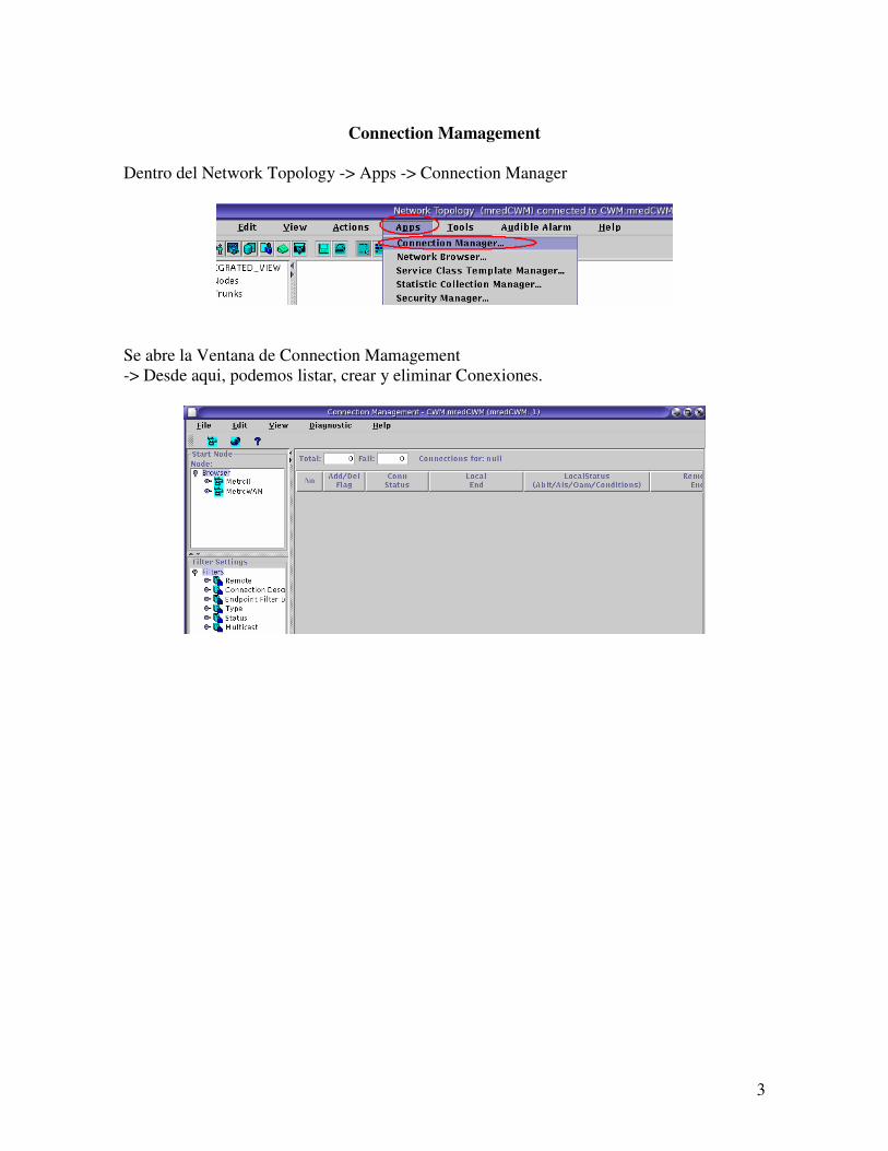
Connection Mamagement
Dentro del Network Topology -> Apps -> Connection Manager
Se abre la Ventana de Connection Mamagement -> Desde aqui, podemos listar, crear y eliminar Conexiones.
4
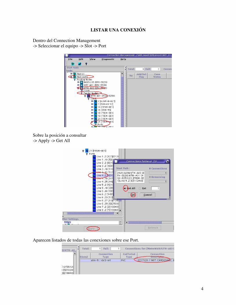
LISTAR UNA CONEXIÓN
Dentro del Connection Management
-> Seleccionar el equipo -> Slot -> Port
Sobre la posición a consultar
-> Apply -> Get All
Aparecen listados de todas las conexiones sobre ese Port.
5
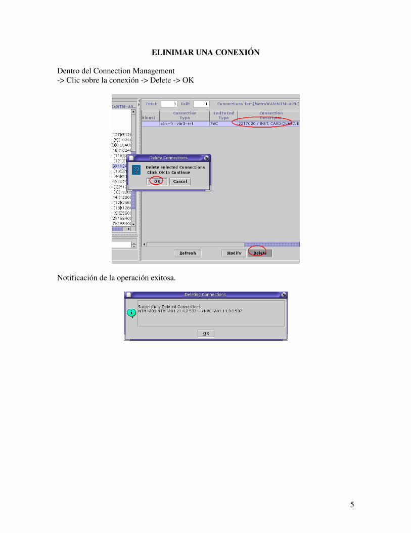
ELINIMAR UNA CONEXIÓN
Dentro del Connection Management
-> Clic sobre la conexión -> Delete -> OK
Notificación de la operación exitosa.
6
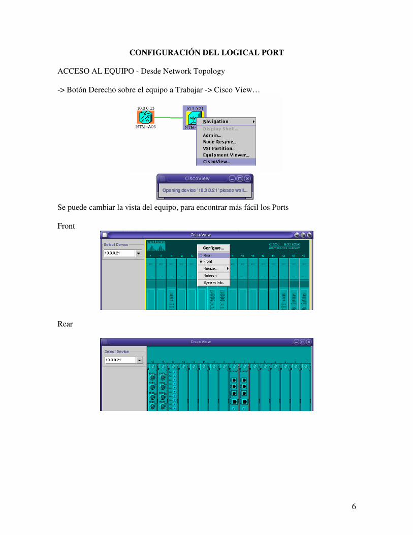
CONFIGURACIÓN DEL LOGICAL PORT
ACCESO AL EQUIPO - Desde Network Topology
-> Botón Derecho sobre el equipo a Trabajar -> Cisco View…
Se puede cambiar la vista del equipo, para encontrar más fácil los Ports
Front
Rear
7
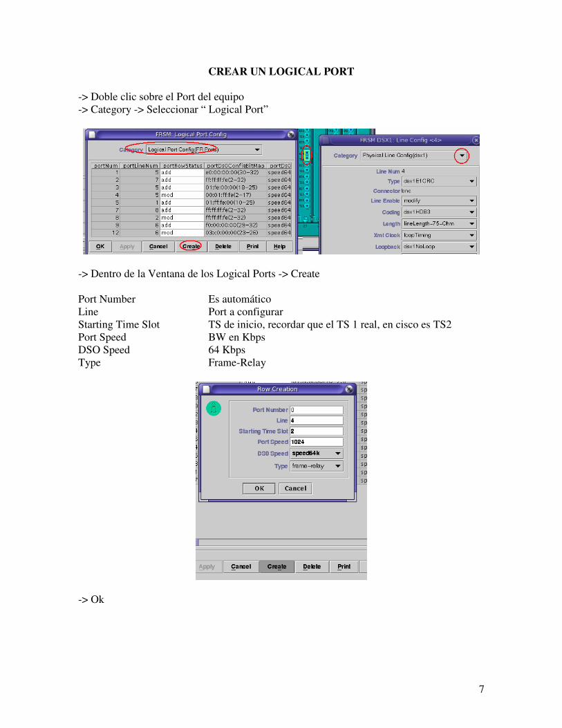
CREAR UN LOGICAL PORT
-> Doble clic sobre el Port del equipo
-> Category -> Seleccionar “ Logical Port”
-> Dentro de la Ventana de los Logical Ports -> Create
Port Number Es automático
Line Port a configurar
Starting Time Slot TS de inicio, recordar que el TS 1 real, en cisco es TS2
Port Speed BW en Kbps
DSO Speed 64 Kbps
Type Frame-Relay
-> Ok
8
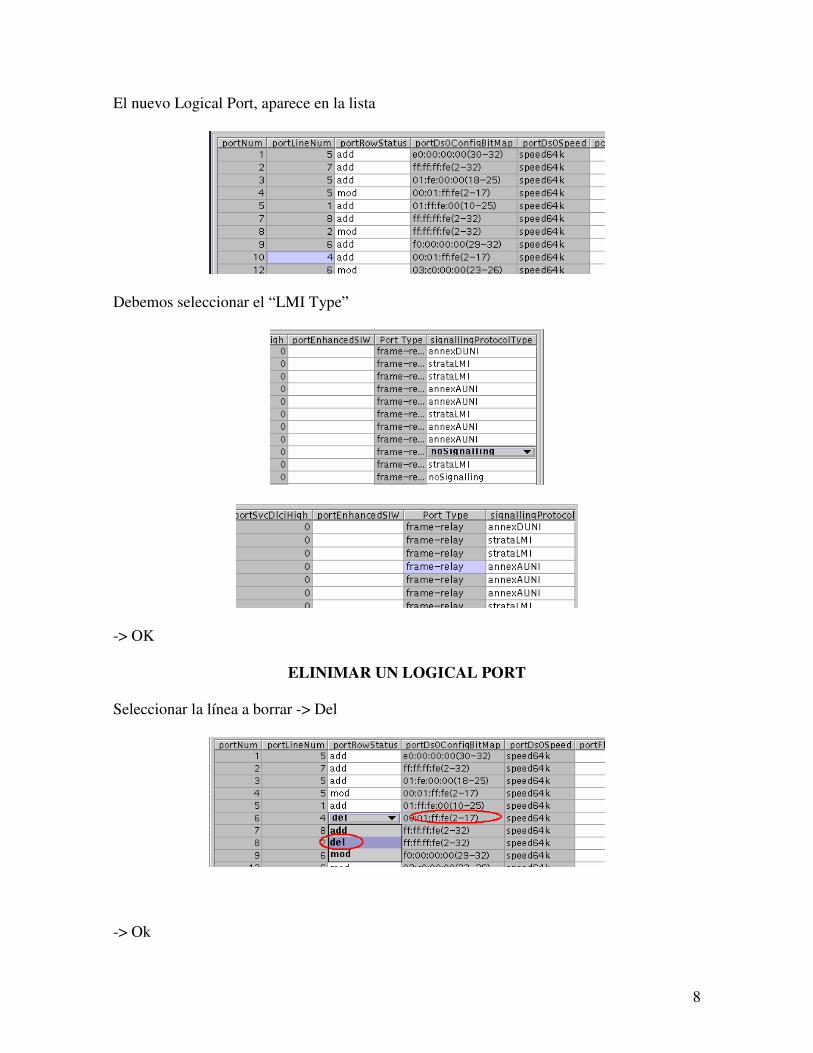
El nuevo Logical Port, aparece en la lista
Debemos seleccionar el “LMI Type”
-> OK
ELINIMAR UN LOGICAL PORT
Seleccionar la línea a borrar -> Del
-> Ok
9
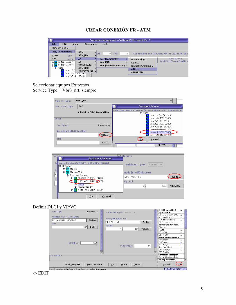
CREAR CONEXIÓN FR - ATM
Seleccionar equipos Extremos
Service Type = Vbr3_nrt, siempre
Definir DLCI y VP/VC
-> EDIT
10
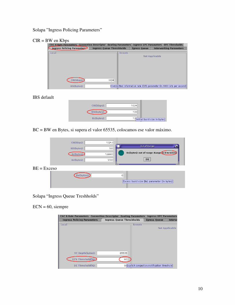
Solapa ”Ingress Policing Parameters”
CIR = BW en Kbps
IBS default
BC = BW en Bytes, si supera el valor 65535, colocamos ese valor máximo.
BE = Exceso
Solapa “Ingress Queue Treshholds”
ECN = 60, siempre
11
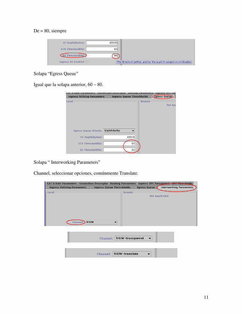
De = 80, siempre
Solapa “Egress Queue”
Igual que la solapa anterior, 60 – 80.
Solapa “ Interworking Parameters”
Channel, seleccionar opciones, comúnmente Translate.
12
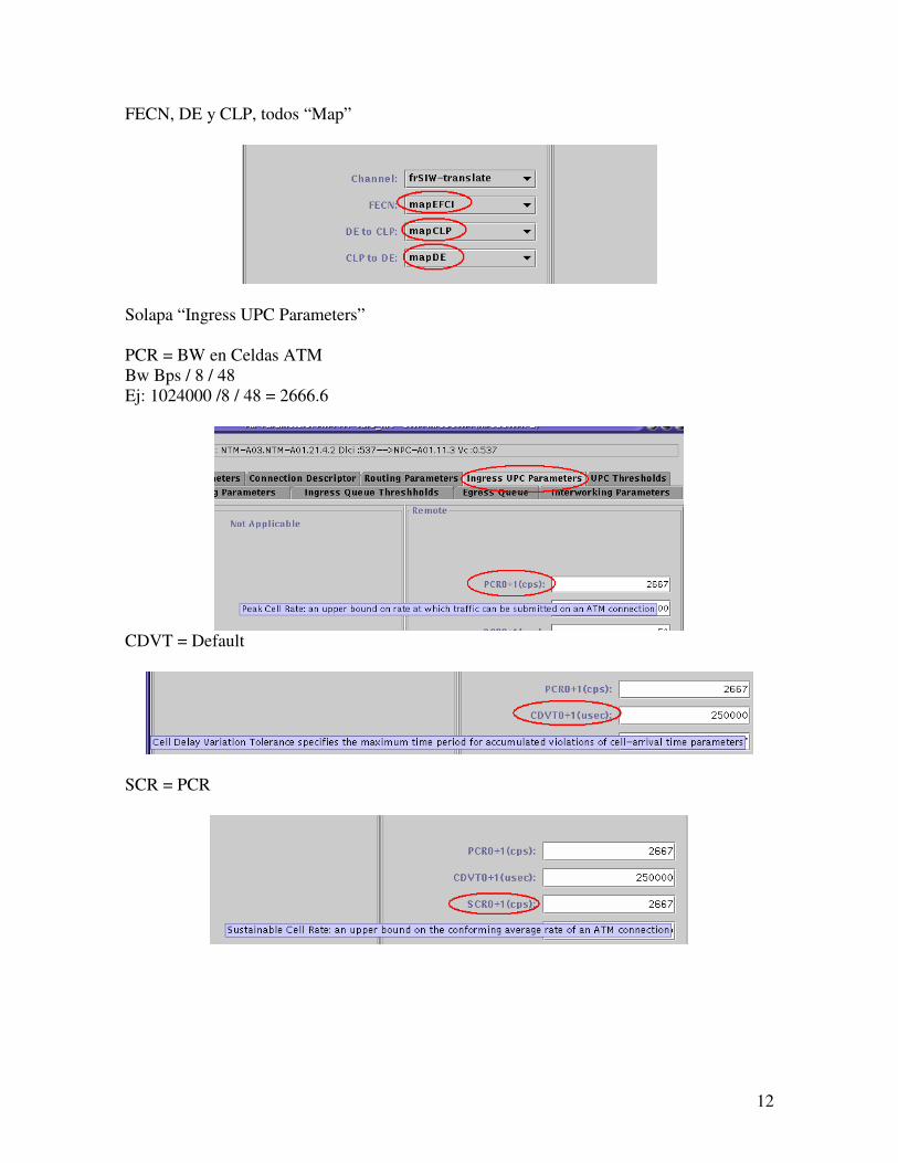
FECN, DE y CLP, todos “Map”
Solapa “Ingress UPC Parameters”
PCR = BW en Celdas ATM
Bw Bps / 8 / 48
Ej: 1024000 /8 / 48 = 2666.6
CDVT = Default
SCR = PCR
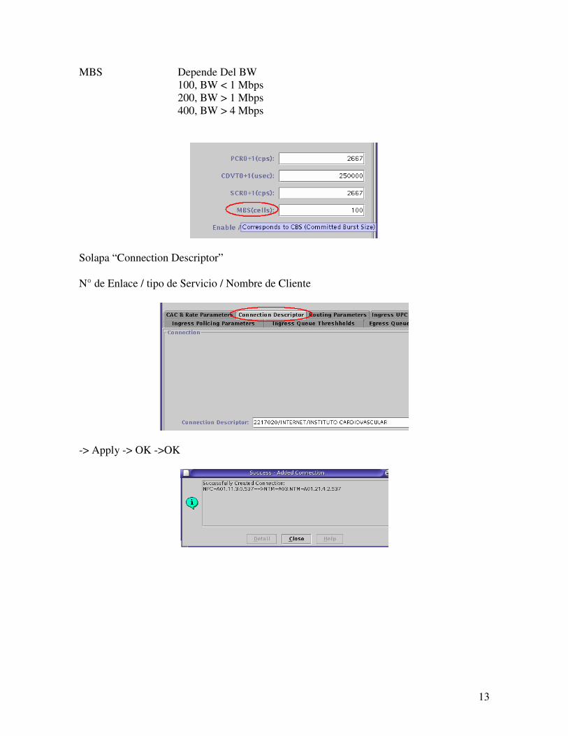
13
MBS Depende Del BW
100, BW < 1 Mbps
200, BW > 1 Mbps
400, BW > 4 Mbps
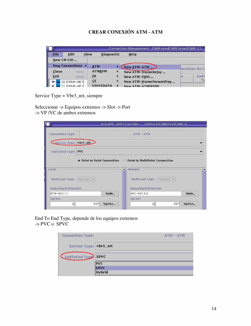
Solapa “Connection Descriptor”
N° de Enlace / tipo de Servicio / Nombre de Cliente
-> Apply -> OK ->OK
14
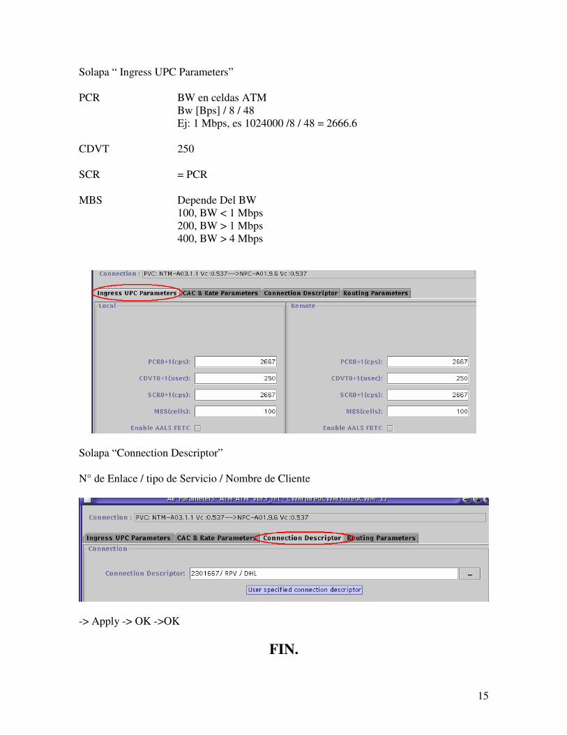
CREAR CONEXIÓN ATM - ATM
Service Type = Vbr3_nrt, siempre
Seleccionar -> Equipos extremos -> Slot -> Port
-> VP /VC de ambos extremos
End To End Type, depende de los equipos extremos
-> PVC o SPVC
15
Solapa “ Ingress UPC Parameters”
PCR BW en celdas ATM
Bw [Bps] / 8 / 48
Ej: 1 Mbps, es 1024000 /8 / 48 = 2666.6
CDVT 250
SCR = PCR
MBS Depende Del BW
100, BW < 1 Mbps
200, BW > 1 Mbps
400, BW > 4 Mbps
Solapa “Connection Descriptor”
N° de Enlace / tipo de Servicio / Nombre de Cliente
-> Apply -> OK ->OK
FIN.


![[Recovery] Cwm Recovery 6.0.3](https://img.pdfslide.us/doc/110x75/55cf9443550346f57ba0c2b8/recovery-cwm-recovery-603.jpg)