Embed Size (px)
Citation preview

Multidisciplinary Research in Transportation
Soojun Ha, Jungheum Yeon, Moon C. Won
Texas Department of Transportation
CRCP ME Design Guide
Report #: 0-5832-P1www.techmrt.ttu.edu/reports.php April 2012
Multidisciplinary Research in Transportation
Texas Tech University | Lubbock, Texas 79409P 806.742.3503 | F 806.742.4168

NOTICE
The United States Government and the State of Texas do not endorse products or manufacturers. Trade or manufacturers’ names appear herein solely because they are considered essential to the object of this report
CRCP ME Design Guide
by
Soojun Ha
Jungheum Yeon
Moon C. Won
Texas Tech University
Project Number 0-5832
Product Number 0-5832-P1
Performed in Cooperation with the Texas Department of Transportation
and the Federal Highway Administration
Texas Tech University Center for Multidisciplinary Research in Transportation
Box 41023 Lubbock, TX 79409-1023

i
Table of Contents
History of Continuously Reinforced Concrete Pavement ..........................................................1
1. CRCP Design .................................................................................................................2
1.1 CRCP Slab Thickness Design ......................................................................2
1.2 Steel Reinforcement Design ........................................................................6
1.3 Summary ....................................................................................................11
1.4 Other Design Issues ...................................................................................12
1.4.1 Transverse Crack Spacing.................................................................12
1.4.2 Crack Width ......................................................................................14
1.4 3 Load Transfer Efficiency (LTE) at Transverse Cracks .....................16
2. Materials ....................................................................................................................17
3. Construction .................................................................................................................18
List of Figures
Figure 1 Crack width variations over time from MEPDG .........................................................5
Figure 2 LTE variations over time from MEPDG .....................................................................5
Figure 3 Longitudinal steel placed at 5 inch from the slab surface .........................................10
Figure 4 Longitudinal steel placed at 3.5 inch from the slab surface ......................................10
Figure 5 Effect of concrete placement time on concrete setting temperature ..........................13
Figure 6 Correlation between crack spacing and crack width .................................................14
Figure 7 Punchout distress with tight crack width ...................................................................15
Figure 8 Effect of crack spacing and time of testing on LTE ..................................................16
Figure 9 Crack spacing and load transfer efficiency from LTPP data .....................................17
Figure 10 Distress at transverse construction joint ..................................................................19
List of Tables
Table 1 Recommended load transfer coefficient for various pavement types and design
conditions ...................................................................................................................................3
Table 2 Current state of practice for CRCP slab thickness and steel design ...........................12

i
1
CRCP ME Design Guide
History of Continuously Reinforced Concrete Pavement
Portland cement concrete (PCC) undergoes volume changes due to temperature and moisture
variations, called environmental loading. In PCC pavement, those volume changes are restrained
by concrete self weight and friction between concrete and subbase, resulting in stresses in
concrete. When wheel loading is applied on concrete pavement, stresses develop in the concrete
pavement. If the combined stresses in concrete due to environmental and wheel loading exceed
concrete strength, cracks will occur. There are two PCC pavement types with significant
differences as to the impacts of cracking potential on their durability. One is jointed plain
concrete pavement (JCP) and the other continuously reinforced concrete pavement (CRCP). In
JCP, transverse contraction joints are provided at certain intervals, usually from 15 ft to 20 ft.
Debonding material, such as plastic sheeting, is provided between the bottom of the concrete slab
and the top of the subbase layer. Relatively short joint spacing and the use of debonding material
allow concrete to move rather freely when there are variations in temperature and moisture in the
concrete. A low level of restraint on concrete volume changes from environmental loading
reduces concrete stress, thus minimizing cracking potential in JCP. On the other hand, in CRCP,
concrete volume changes due to temperature and moisture variations are highly restrained by
longitudinal steel and subbase friction, resulting in high concrete stresses and numerous
transverse cracks. The cracks are kept tightly closed. In CRCP, longitudinal steel is placed
continuously throughout the project, except at bridges. No intermediate transverse expansion or
contraction joints are used. The basic concept of this pavement is quite different from that of JCP,
where cracks are considered a distress. In CRCP, cracks are not considered a distress.
In the U.S., there are many more lane miles of JCP than CRCP. Most of the national research on
PCC pavement was on JCP. For example, JCP and jointed reinforced concrete pavement (JRCP)
were included in the AASHO Road Test, but not CRCP. Extensive research on JCP, compared to
CRCP, produced valuable information on JCP behavior and performance. On the other hand,
there have been only a few national research projects on CRCP that were funded by national
research organizations such as NCHRP (National Cooperative Highway Research Program). It
was natural that much of the findings on JCP were applied to CRCP, even though the behaviors
of the two pavement types are fundamentally different.
The first experimental CRCP section was built in 1921 by the Bureau of Public Roads on
Columbia Pike in Arlington, Virginia. The first significant length of CRCP was constructed by
the State of Indiana in 1938 (Highway Research Board, 1973). The performance of the Indiana
project and other projects (built in Illinois, California, and New Jersey around 1949) led to an
increased interest in this design (AASHTO, 1986). The use of CRCP expanded in the 1960s,
1970s, and 1980s during construction of the Interstate Highway System, where it constituted
important stretches of roadway in various parts of the U.S (Plei). Installations of CRCP have
increased until more than 10,000 miles of equivalent two-lane pavement were in use or under
2
contract at the end of 1971(Highway Research Board, 1973). To date, over 28,000 lane-miles of
CRCP have been built in the U.S. More than 35 states have built CRCP, at least on a trial basis,
including Texas, Illinois, Oklahoma, Oregon, South Dakota and Virginia (ERES, 2001).
Texas leads the nation in CRCP usage. Texas constructed its first experimental section in Ft.
Worth in 1951, which became a part of IH35E. It was 8-in CRCP slab on 8-in crushed stone
subbase with two course treatment. The longitudinal steel amount was 0.7 %. From the 1960s on,
Texas has constructed more CRCP than any other state, possibly more than all other states
combined. As of 2010, Texas had 12,345 lane miles of CRCP, which is about 6.3 % of the total
lane miles in the state.
1. CRCP Design
CRCP design consists of two elements: slab thickness design and steel reinforcement design. The
two design elements are inter-related; however, the design for each element evolved
independently until a mechanistic-empirical pavement design guide (referred to as MEPDG in
this document) developed under NCHRP 1-37(A) was released (ERES, 2004). In this document,
historical developments in design procedure for each element are separately described.
1.1 CRCP Slab Thickness Design
The first national CRCP design procedure for slab thickness appeared in the “1972 AASHTO
Interim Guide for Design of Pavement Structures,” referred to as the “72 Interim Guide” in this
document (AASHTO, 1980). Design methods in the 72 Interim Guide are based solely on the
AASHO Road Test, where CRCP was not included. The primary distress in rigid pavements in
the AASHO Road Test was cracking which developed along wheel paths. Structural
deterioration of rigid pavement in the AASHO Road Test is described as follows in the Summary
Report of The AASHO Road Test (Highway Research Board, 1962):
“Rigid pavements lost serviceability when they developed roughness along the wheel
paths, when cracking developed, and when it was necessary to patch the pavement
surface.”
The deterioration mechanism and design method developed to address this distress is not
applicable to CRCP. As discussed earlier, cracking in JCP is considered a distress, since almost
no load transfer is provided along the cracks, which will result in further deterioration and
roughness. In CRCP, transverse cracking is expected and does not constitute a distress.
Transverse cracks are held quite tight with an adequate amount of longitudinal steel and do not
necessarily cause distress. In addition, cracks and necessary repairs in JCP result in the
degradation of pavement serviceability. Accordingly, the use of the findings in the AASHO
Road Test for the design of CRCP has severe limitations, and the design thus developed may not
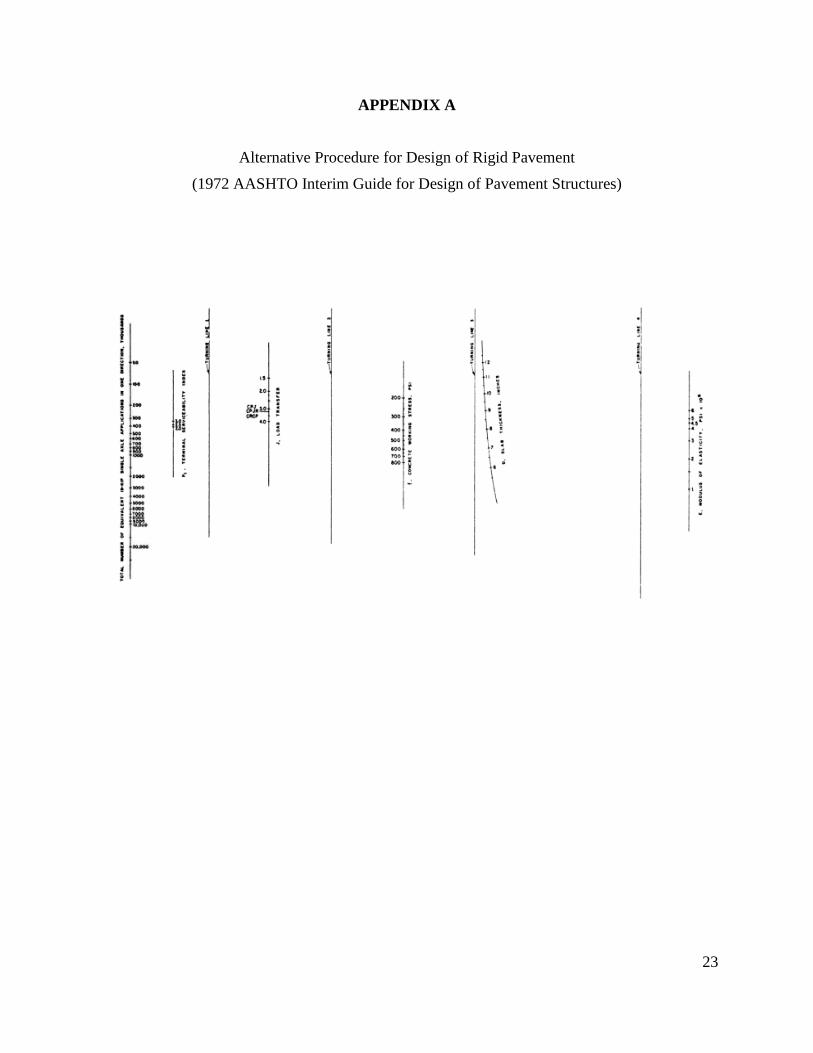
be technically valid for CRCP. In the 72 Interim Guide, CRCP slab thickness design was
included in the Appendix D.4 “Alternate Procedure for the Design of Rigid Pavement Structures.”
In the Procedure, the only difference between JCP and CRCP is the use of different values for
3
load transfer. The 72 Interim Guide does not provide suggested values for the appropriate load
transfer for different pavement types. Instead, a “continuity factor” of 3.2 was used for both JCP
and CRCP in example problems, which implied that the required slab thickness for CRCP is the
same as that for JCP. The slab thickness design nomograph for rigid pavement in the 72 Interim
Guide is included in Appendix A.
In 1984, PCA (Portland Cement Association) developed the rigid pavement slab thickness design
method (PCA, 1984). Critical stresses and deflections were identified from a computer program
JSLAB, and design tables and charts were developed based on design criteria. In this method,
critical stresses and deflections were estimated at the pavement edge. The unique feature of this
procedure is that fatigue and erosion damages are estimated separately using various tables and
charts. Since the analysis for critical stresses and deflections were based on JCP, this design
method is not directly applicable for the design of CRCP.
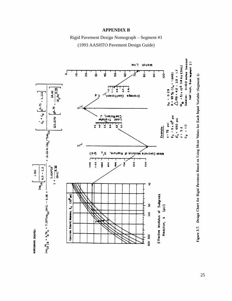
The next milestone in the CRCP slab thickness design was the “AASHTO Guide for Design of
Pavement Structures” published in 1993, referred to as the “1993 Guide” in this document
(AASHTO, 1993). The design nomograph is included in Appendix B. The detailed description of
this design method is provided in the “AASHTO Guide for Design of Pavement Structures”
(AASHTO, 1993), and not repeated in this document. To automate the design procedure, a
software program called Darwin was developed as well. Unlike the 72 Interim Guide, the 1993
Guide provides recommendations for “load transfer coefficient” for various pavement types and
design conditions. Table 1 shows the recommended values. These values were developed based
on “equal concrete stress” at transverse joints or cracks. From Table 1, it is noted that required
slab thickness in CRCP would be less than that for JCP.
Shoulder Asphalt Tied P.C.C.
Load Transfer
Devices
Yes No Yes No
Pavement Type
1. Plain jointed
and jointed
reinforced
3.2 3.8-4.4 2.5-3.1 3.6-4.2
2. CRCP 2.9-3.2 N/A 2.3-2.9 N/A
Table 1. Recommended load transfer coefficient for various pavement
types and design conditions
The slab thickness design method in the 93 Guide has the same limitations as the 72 Interim
Guide for CRCP design, which is, the design method was developed based on the AASHO Road
Test, and the distress mechanisms in CRCP and their effects on serviceability of pavement were
not properly addressed.
In 2004, MEPDG was released. This procedure is technically superior and more comprehensive
than any other procedures developed up to that point. This procedure did not directly utilize any
information from the AASHO Road Test. In this procedure, a number of punchouts and IRI
(International Roughness Index) are the performance variables, not PSI (Present Serviceability
4
Index). In the thickness design, it was assumed that IRI depends on the number of punchouts
among other design and construction variables. Accordingly, the prediction of the number of
punchouts constitutes the core of this procedure. The punchout mechanism adopted in this
procedure can be summarized as follows (ERES, 2004):
1) With continued drying shrinkage of concrete, crack widths increase over time.
2) As crack widths increase, load transfer efficiency (LTE) at transverse cracks decreases.
Application of repeated truck wheel loading further degrades LTE through the loss of
aggregate interlock at transverse cracks.
3) With lower LTE at transverse cracks along with pumping at pavement edge, concrete
stress due to wheel loads at the top of the slab in the transverse direction, at 4 ft from the
slab edge, increases.
4) When the accumulated fatigue damage at the top of the concrete slab exceeds the critical
fatigue damage, longitudinal crack occurs at 4 ft from the slab edge and punchouts result.
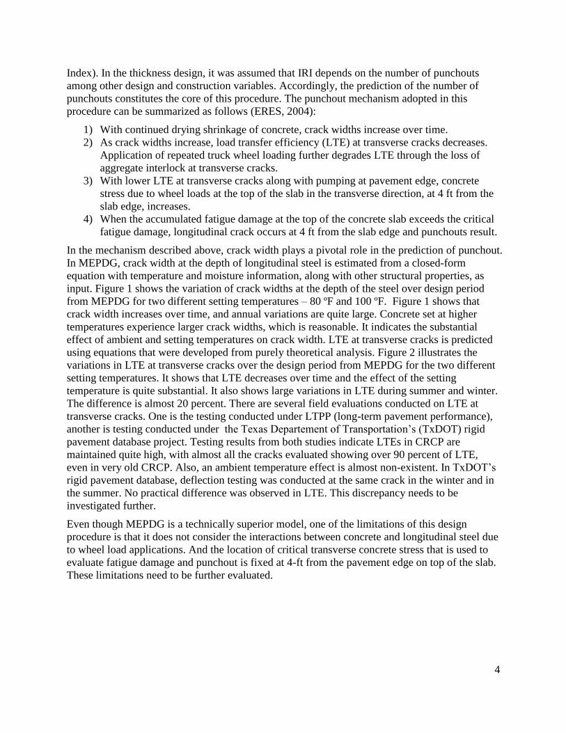
In the mechanism described above, crack width plays a pivotal role in the prediction of punchout.
In MEPDG, crack width at the depth of longitudinal steel is estimated from a closed-form
equation with temperature and moisture information, along with other structural properties, as
input. Figure 1 shows the variation of crack widths at the depth of the steel over design period
from MEPDG for two different setting temperatures – 80 ºF and 100 ºF. Figure 1 shows that
crack width increases over time, and annual variations are quite large. Concrete set at higher
temperatures experience larger crack widths, which is reasonable. It indicates the substantial
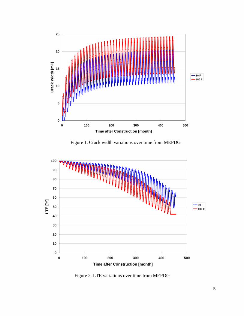
effect of ambient and setting temperatures on crack width. LTE at transverse cracks is predicted
using equations that were developed from purely theoretical analysis. Figure 2 illustrates the
variations in LTE at transverse cracks over the design period from MEPDG for the two different
setting temperatures. It shows that LTE decreases over time and the effect of the setting
temperature is quite substantial. It also shows large variations in LTE during summer and winter.
The difference is almost 20 percent. There are several field evaluations conducted on LTE at
transverse cracks. One is the testing conducted under LTPP (long-term pavement performance),
another is testing conducted under the Texas Departement of Transportation’s (TxDOT) rigid
pavement database project. Testing results from both studies indicate LTEs in CRCP are
maintained quite high, with almost all the cracks evaluated showing over 90 percent of LTE,
even in very old CRCP. Also, an ambient temperature effect is almost non-existent. In TxDOT’s
rigid pavement database, deflection testing was conducted at the same crack in the winter and in
the summer. No practical difference was observed in LTE. This discrepancy needs to be
investigated further.
Even though MEPDG is a technically superior model, one of the limitations of this design
procedure is that it does not consider the interactions between concrete and longitudinal steel due
to wheel load applications. And the location of critical transverse concrete stress that is used to
evaluate fatigue damage and punchout is fixed at 4-ft from the pavement edge on top of the slab.
These limitations need to be further evaluated.
5
Figure 1. Crack width variations over time from MEPDG
Figure 2. LTE variations over time from MEPDG
0
5
10
15
20
25
0 100 200 300 400 500
Time after Construction [month]
Cra
ck W
idth
[m
il]
80 F
100 F
0
10
20
30
40
50
60
70
80
90
100
0 100 200 300 400 500
Time after Construction [month]
LT
E [
%]
80 F
100 F
6
1.2 Steel Reinforcement Design
Longitudinal steel reinforcement in CRC pavements induces transverse cracks and holds them
tightly closed, thereby providing structural continuity of the slab at the cracks. Pavement
responses depend not only on the amount of reinforcing steel but also bar size, location, and
number of layers of the steel bars.
Reinforcement design in CRCP is discussed in the following four categories:
longitudinal steel amount
bar size and spacing
depth
number of layers
Longitudinal steel amount: Steel design equations developed in the early usage of CRCP were
based on the mechanical equilibrium in stresses from temperature variations. In 1933, Vetter
presented an analysis of the stresses occurring in a continuous reinforced concrete structure
owing to variations in temperature and moisture content (Vetter, 1933). Vetter’s formula for
minimum reinforcement is as follows:
p = ft
fy- nft (1)
where,
P = steel percentage of longitudinal reinforcement.
= concrete tensile strength (psi),
= yield strength of steel (psi), and
n = the ratio of modulus of elasticity of steel to concrete.
The yield strength of steel in CRCP is usually 60,000 psi. If 4 million and 29 million psi are
taken for modulus of elasticity of concrete and steel, respectively, and concrete tensile strength is
assumed to be 420 psi at 28 days, equation (1) yields 0.737 percent. Field performance of CRCP
shows that this value constitutes the upper limit of the steel amount needed in CRCP.
The 1972 Interim Guide recommends the following relationship:
P = -
(2)
where,
7
F = friction factor of subbase,
= tensile strength of concrete (psi), and
= allowable working stress in steel (psi).
In this formula, the percent steel reinforcement (p) is directly proportional to the concrete tensile
strength. With 1.5 for friction factor, 420 psi for concrete tensile strength and 40,000 psi for
allowable steel working stress, it yields 1.1 %, which is much greater than the amount of steel
used in the CRCP.
In the 1986 AASHTO Guide for Design of Pavement Structures (AASHTO, 1986), a separate
formula is recommended considering crack spacing, crack width, and steel stress at a crack.
X =
(3)
ΔX =
(4)
σs =
(5)
where,
X = crack spacing (feet),
ΔX = crack width (inches),
σs = steel stress (psi),
ft = concrete tensile strength (psi).
= thermal coefficient of steel (inch/inch/°F),
= thermal coefficient of concrete (inch/inch/°F),
= rebar diameter (inches),
wheel load tensile stress (psi),
P = percent steel reinforcement,
Z = concrete shrinkage (inch/inch), and
= design temperature drop (°F).
8
The desired crack spacing range is selected, and equation (3) is solved for percentage of steel.
For crack width and steel stress, maximum allowable values are selected and equations (4) and (5)
are solved. The design percentage of steel is selected which satisfies all three required criteria.
The above three equations were developed from a one-dimensional theoretical model, and the
effect of temperature variations through the slab depth was not considered, which limits the
value of the equations. When appropriate input values are substituted into the above three
equations, the resulting steel amount is usually lower than what’s needed. These equations have
rarely been used in real CRCP projects.
As described earlier, MEPDG is a technically superior program. In MEPDG, crack widths are
estimated for ambient temperature and moisture variations on a monthly basis. Steel amount is
incorporated into the program by its effect on crack spacing and crack width. The process is
quite complicated and is well documented in the Appendix LL, “Punchout Development in
Continuously Reinforced Concrete Pavements” (ERES, 2004).
Most states have standardized the percentage of longitudinal steel by specifying the requirements
in their design standards, as TxDOT does. By far, the most commonly used amount of steel is
between 0.6 and 0.7 percent. Field performances of CRCP nationwide show that the amount of
steel between 0.6 and 0.7 percent provides satisfactory performance.
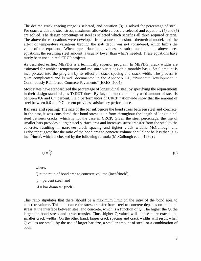
Bar size and spacing: The size of the bar influences the bond stress between steel and concrete.
In the past, it was considered that bond stress is uniform throughout the length of longitudinal
steel between cracks, which is not the case in CRCP. Given the steel percentage, the use of
smaller bars provides a larger steel surface area and increases stress transfer from the steel to the
concrete, resulting in narrower crack spacing and tighter crack widths. McCullough and
Ledbetter suggest that the ratio of the bond area to concrete volume should not be less than 0.03
inch2/inch
3, which is checked by the following formula (McCullough et al., 1960) :
Q =
(6)
where,
Q = the ratio of bond area to concrete volume (inch2/inch
3),
p = percent steel, and
= bar diameter (inch).
This ratio stipulates that there should be a maximum limit on the ratio of the bond area to
concrete volume. This is because the stress transfer from steel to concrete depends on the bond
stress at the interface between steel and concrete, which is a function of Q. The higher the Q, the
larger the bond stress and stress transfer. Thus, higher Q values will induce more cracks and
smaller crack widths. On the other hand, larger crack spacing and crack widths will result when
Q values are small, by the use of larger bar size, a smaller amount of steel, or a combination of
both.
9
Even though Q factor is discussed in the 1986 AASHTO Guide, it is no longer considered in the
steel design in the 1993 Design Guide.
The spacing of steel should be large enough to permit easy placement and consolidation of
concrete. The Continuously Reinforced Pavement Group recommends that longitudinal spacing
not be less than 4 inches nor more than 9 inches, to provide good load transfer and bond strength.
Steel placement depth: The upper portion of concrete undergoes most of the volume changes
due to the largest temperature and moisture variations in that area. Placing steel where concrete
volume change potential is at a maximum would induce more cracks, and potentially cause
delamination at that depth. Most of the states in the US place steel at the mid-depth of the slab.
However, Illinois places steel in the upper 1/3 of the slab for thicker slabs, and 3.5-in from the
surface for thin slabs (CRSI, 2001). Surface delamination distresses were observed when the
steel is placed closer to the surface. Also, the steel corrosion potential increases as steel is placed
near the surface. In Texas, steel is placed at the mid-depth and the performance has been quite
good. Experiments conducted under the TxDOT research study show that when the steel is
placed above the mid-depth by 2.5-in, the steel stress increased substantially, which supports the
practice in Texas. Another problem with placing steel too close to the surface is that longitudinal
saw cutting operation might cut the transverse steel at longitudinal warping joints or tie bars at
longitudinal construction joints, which will reduce CRCP performance.
This issue needs to be resolved, since Texas, the largest user of CRCP in the US places the steel
at the mid-depth, while Illinois, the second largest user of CRCP in the US places closer to the
top. The only steel design method that considers the depth of the steel in the analysis is MEPDG.
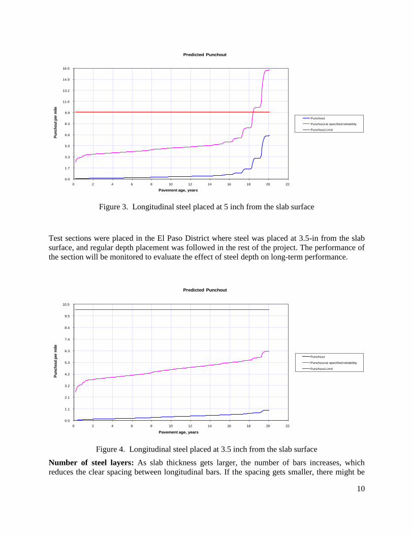
According to MEPDG, steel depth has a significant effect on performance. An example run of
MEPDG shows that when the steel was placed at the mid-depth of a 10-in slab (5-in from slab
surface), about 16 punchouts per mile were predicted at the end of a 20-year design period as
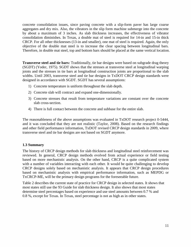
shown in Figure 3. With all variables being the same, with the exception of steel placement depth
at 3.5-in from the slab surface, the number of punchouts per mile at the end of the 20-year design
period was about 6, as shown in Figure 4. This difference is quite large, and if placing steel near
the slab surface improves CRCP performance as much as the MEPDG outputs predict, TxDOT
might consider changing the depth requirement of steel.
10
Figure 3. Longitudinal steel placed at 5 inch from the slab surface
Test sections were placed in the El Paso District where steel was placed at 3.5-in from the slab
surface, and regular depth placement was followed in the rest of the project. The performance of
the section will be monitored to evaluate the effect of steel depth on long-term performance.
Figure 4. Longitudinal steel placed at 3.5 inch from the slab surface
Number of steel layers: As slab thickness gets larger, the number of bars increases, which
reduces the clear spacing between longitudinal bars. If the spacing gets smaller, there might be
0.0
1.7
3.3
5.0
6.6
8.3
9.9
11.6
13.2
14.9
16.5
0 2 4 6 8 10 12 14 16 18 20 22
Pu
nch
ou
t p
er
mile
Pavement age, years
Predicted Punchout
Punchout
Punchout at specified reliability
Punchout Limit
0.0
1.1
2.1
3.2
4.2
5.3
6.3
7.4
8.4
9.5
10.5
0 2 4 6 8 10 12 14 16 18 20 22
Pu
nch
ou
t p
er
mile
Pavement age, years
Predicted Punchout
Punchout
Punchout at specified reliability
Punchout Limit
11
concrete consolidation issues, since paving concrete with a slip-form paver has large coarse
aggregates and dry mix. Also, the vibrators in the slip form machine submerge into the concrete
by about a maximum of 3 inches. As slab thickness increases, the effectiveness of vibrator
consolidation diminishes. In Texas, a double mat of steel is required for 14-in and 15-in thick
CRCP. For all other thicknesses (13-in and smaller), one mat of steel is required. Again, the only
objective of the double mat steel is to increase the clear spacing between longitudinal bars.
Therefore, in double mat steel, top and bottom bars should be placed at the same vertical location.
Transverse steel and tie bars: Traditionally, tie bar designs were based on subgrade drag theory
(SGDT) (Yoder, 1975). SGDT shows that the stresses at transverse steel at longitudinal warping
joints and the stresses in tie bars at longitudinal construction joints are proportional to the slab
widths. Until 2003, transverse steel and tie bar designs in TxDOT CRCP design standards were
designed in accordance with SGDT. SGDT has several assumptions:
1) Concrete temperature is uniform throughout the slab depth.
2) Concrete slab will contract and expand one-dimensionally.
3) Concrete stresses that result from temperature variations are constant over the concrete
slab cross-section.
4) There is full contact between the concrete and subbase for the entire slab.
The reasonableness of the above assumptions was evaluated in TxDOT research project 0-5444,
and it was concluded that they are not realistic (Taylor, 2008). Based on the research findings
and other field performance information, TxDOT revised CRCP design standards in 2009, where
transverse steel and tie bar designs are not based on SGDT anymore.
1.3 Summary
The history of CRCP design methods for slab thickness and longitudinal steel reinforcement was
reviewed. In general, CRCP design methods evolved from actual experience or field testing
based on more mechanistic analysis. On the other hand, CRCP is a quite complicated system
with a number of variables interacting with each other. It would be quite challenging to develop
CRCP designs solely based on mechanistic analysis. It appears that CRCP design procedures
based on mechanistic analysis with empirical performance information, such as MEPDG or
TxCRCP-ME, will be the primary design programs for the foreseeable future.
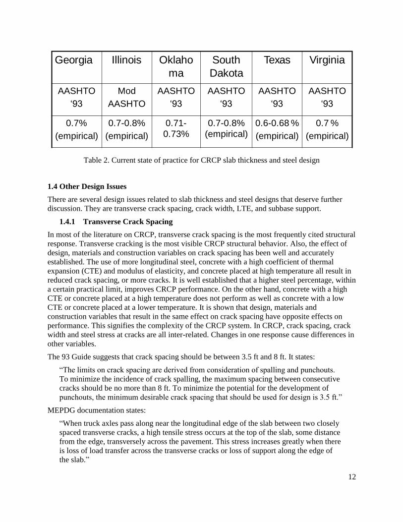
Table 2 describes the current state of practice for CRCP design in selected states. It shows that
most states still use the 93 Guide for slab thickness design. It also shows that most states
determine steel percentages based on experience and use steel amounts between 0.7 % and
0.8 %, except for Texas. In Texas, steel percentage is not as high as in other states.
12
Table 2. Current state of practice for CRCP slab thickness and steel design
1.4 Other Design Issues
There are several design issues related to slab thickness and steel designs that deserve further
discussion. They are transverse crack spacing, crack width, LTE, and subbase support.
1.4.1 Transverse Crack Spacing
In most of the literature on CRCP, transverse crack spacing is the most frequently cited structural
response. Transverse cracking is the most visible CRCP structural behavior. Also, the effect of
design, materials and construction variables on crack spacing has been well and accurately
established. The use of more longitudinal steel, concrete with a high coefficient of thermal
expansion (CTE) and modulus of elasticity, and concrete placed at high temperature all result in
reduced crack spacing, or more cracks. It is well established that a higher steel percentage, within
a certain practical limit, improves CRCP performance. On the other hand, concrete with a high
CTE or concrete placed at a high temperature does not perform as well as concrete with a low
CTE or concrete placed at a lower temperature. It is shown that design, materials and
construction variables that result in the same effect on crack spacing have opposite effects on
performance. This signifies the complexity of the CRCP system. In CRCP, crack spacing, crack
width and steel stress at cracks are all inter-related. Changes in one response cause differences in
other variables.
The 93 Guide suggests that crack spacing should be between 3.5 ft and 8 ft. It states:
“The limits on crack spacing are derived from consideration of spalling and punchouts.
To minimize the incidence of crack spalling, the maximum spacing between consecutive
cracks should be no more than 8 ft. To minimize the potential for the development of
punchouts, the minimum desirable crack spacing that should be used for design is 3.5 ft.”
MEPDG documentation states:
“When truck axles pass along near the longitudinal edge of the slab between two closely
spaced transverse cracks, a high tensile stress occurs at the top of the slab, some distance
from the edge, transversely across the pavement. This stress increases greatly when there
is loss of load transfer across the transverse cracks or loss of support along the edge of
the slab.”
Georgia Illinois Oklaho
ma
South
Dakota
Texas Virginia
AASHTO
‘93
Mod
AASHTO
AASHTO
‘93
AASHTO
‘93
AASHTO
‘93
AASHTO
‘93
0.7%
(empirical)
0.7-0.8%
(empirical)
0.71-
0.73%
0.7-0.8%
(empirical)
0.6-0.68 %
(empirical)
0.7 %
(empirical)
13
Both documents imply that short transverse crack spacing is not desirable as it will increase the
potential for punchouts. On the other hand, field evaluations show that transverse cracks with
short spacing do not necessarily cause punchouts. It appears that slab support, not crack spacing,
is more responsible for punchouts, as will be discussed later.
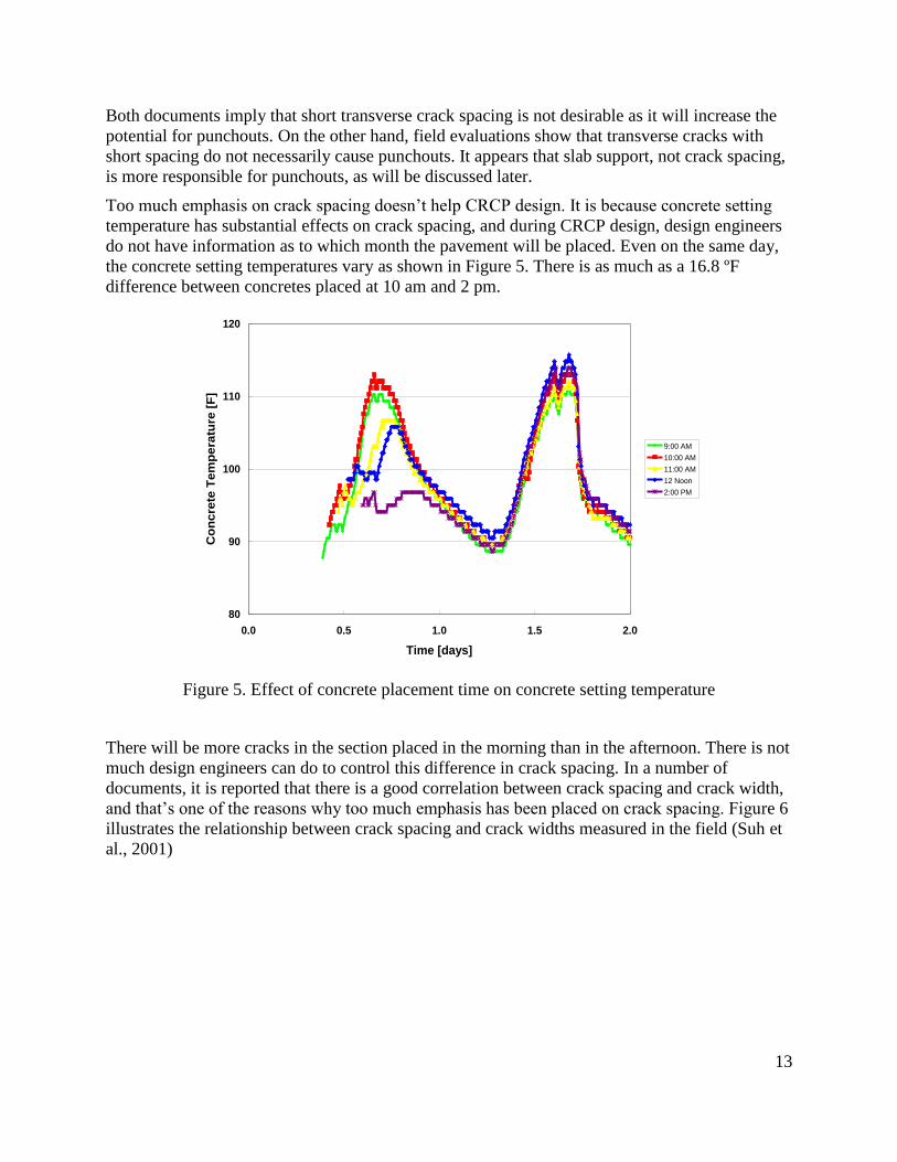
Too much emphasis on crack spacing doesn’t help CRCP design. It is because concrete setting
temperature has substantial effects on crack spacing, and during CRCP design, design engineers
do not have information as to which month the pavement will be placed. Even on the same day,
the concrete setting temperatures vary as shown in Figure 5. There is as much as a 16.8 ºF
difference between concretes placed at 10 am and 2 pm.
Figure 5. Effect of concrete placement time on concrete setting temperature
There will be more cracks in the section placed in the morning than in the afternoon. There is not
much design engineers can do to control this difference in crack spacing. In a number of
documents, it is reported that there is a good correlation between crack spacing and crack width,
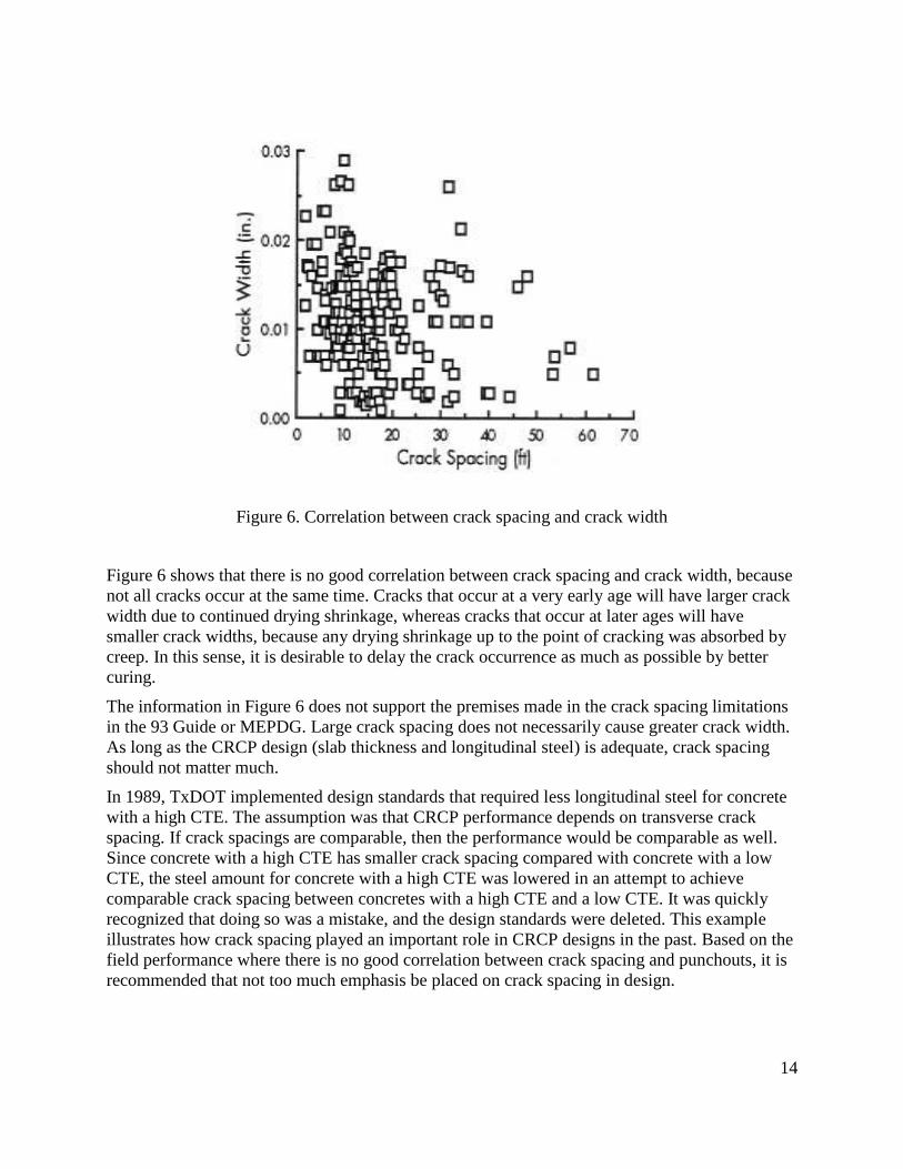
and that’s one of the reasons why too much emphasis has been placed on crack spacing. Figure 6
illustrates the relationship between crack spacing and crack widths measured in the field (Suh et
al., 2001)
80
90
100
110
120
0.0 0.5 1.0 1.5 2.0
Time [days]
Co
ncre
te T
em
pera
ture
[F
]
9:00 AM
10:00 AM
11:00 AM
12 Noon
2:00 PM
14
Figure 6. Correlation between crack spacing and crack width
Figure 6 shows that there is no good correlation between crack spacing and crack width, because
not all cracks occur at the same time. Cracks that occur at a very early age will have larger crack
width due to continued drying shrinkage, whereas cracks that occur at later ages will have
smaller crack widths, because any drying shrinkage up to the point of cracking was absorbed by
creep. In this sense, it is desirable to delay the crack occurrence as much as possible by better
curing.
The information in Figure 6 does not support the premises made in the crack spacing limitations
in the 93 Guide or MEPDG. Large crack spacing does not necessarily cause greater crack width.
As long as the CRCP design (slab thickness and longitudinal steel) is adequate, crack spacing
should not matter much.
In 1989, TxDOT implemented design standards that required less longitudinal steel for concrete
with a high CTE. The assumption was that CRCP performance depends on transverse crack
spacing. If crack spacings are comparable, then the performance would be comparable as well.
Since concrete with a high CTE has smaller crack spacing compared with concrete with a low
CTE, the steel amount for concrete with a high CTE was lowered in an attempt to achieve
comparable crack spacing between concretes with a high CTE and a low CTE. It was quickly
recognized that doing so was a mistake, and the design standards were deleted. This example
illustrates how crack spacing played an important role in CRCP designs in the past. Based on the
field performance where there is no good correlation between crack spacing and punchouts, it is
recommended that not too much emphasis be placed on crack spacing in design.
15
1.4.2 Crack Width
Crack width has been cited as one of the most important variables determining CRCP
performance. If cracks are not kept tight, the basic premise of CRCP – longitudinal steel keeps
cracks tight so that there is good load transfer and water cannot get into cracks, so the steel is
protected from corrosion – is violated. Therefore, it is quite important to keep the cracks tight.
There are things that can be done to keep the cracks as tight as possible. They include the use of
an adequate amount of longitudinal steel, better curing, and the use of concrete with a smaller
CTE, to name a few. However, manipulating design variables to induce more cracks (smaller
crack spacing) would not be a proper practice, as can be seen in Figure 6. Field evaluations of
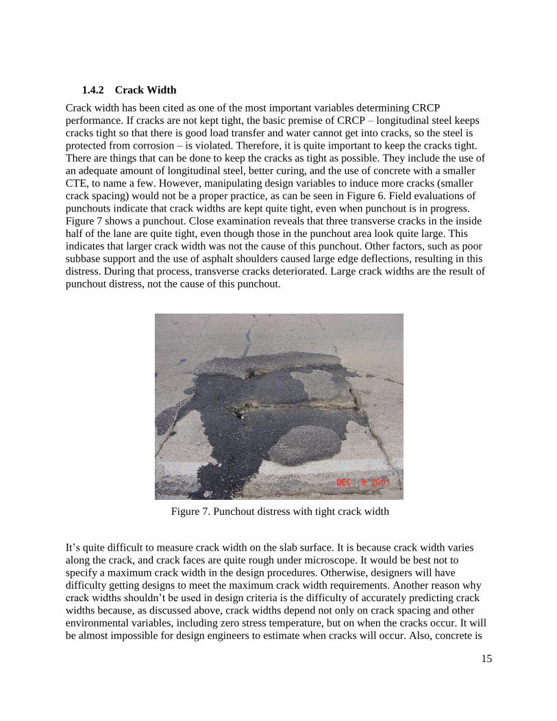
punchouts indicate that crack widths are kept quite tight, even when punchout is in progress.
Figure 7 shows a punchout. Close examination reveals that three transverse cracks in the inside
half of the lane are quite tight, even though those in the punchout area look quite large. This
indicates that larger crack width was not the cause of this punchout. Other factors, such as poor
subbase support and the use of asphalt shoulders caused large edge deflections, resulting in this
distress. During that process, transverse cracks deteriorated. Large crack widths are the result of
punchout distress, not the cause of this punchout.
Figure 7. Punchout distress with tight crack width
It’s quite difficult to measure crack width on the slab surface. It is because crack width varies
along the crack, and crack faces are quite rough under microscope. It would be best not to
specify a maximum crack width in the design procedures. Otherwise, designers will have
difficulty getting designs to meet the maximum crack width requirements. Another reason why
crack widths shouldn’t be used in design criteria is the difficulty of accurately predicting crack
widths because, as discussed above, crack widths depend not only on crack spacing and other
environmental variables, including zero stress temperature, but on when the cracks occur. It will
be almost impossible for design engineers to estimate when cracks will occur. Also, concrete is
16
not a purely elastic material, especially when the loading rate is quite small, such as temperature
variations in concrete. Concrete exhibits visco-elastic behavior, making it extremely complicated
to predict the timing of cracks and resulting crack widths.
A more desirable design practice would be to use an adequate amount of longitudinal steel along
with good design practices – the use of stabilized, non-erodible subbase, tied concrete shoulder
and adequate slab thickness – and cracks will be kept quite tight.
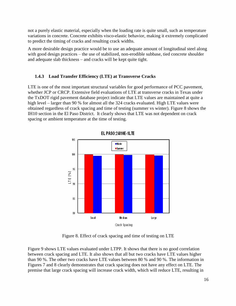
1.4.3 Load Transfer Efficiency (LTE) at Transverse Cracks
LTE is one of the most important structural variables for good performance of PCC pavement,
whether JCP or CRCP. Extensive field evaluations of LTE at transverse cracks in Texas under
the TxDOT rigid pavement database project indicate that LTE values are maintained at quite a
high level – larger than 90 % for almost all the 324 cracks evaluated. High LTE values were
obtained regardless of crack spacing and time of testing (summer vs winter). Figure 8 shows the
IH10 section in the El Paso District. It clearly shows that LTE was not dependent on crack
spacing or ambient temperature at the time of testing.
Figure 8. Effect of crack spacing and time of testing on LTE
Figure 9 shows LTE values evaluated under LTPP. It shows that there is no good correlation
between crack spacing and LTE. It also shows that all but two cracks have LTE values higher
than 90 %. The other two cracks have LTE values between 80 % and 90 %. The information in
Figures 7 and 8 clearly demonstrates that crack spacing does not have any effect on LTE. The
premise that large crack spacing will increase crack width, which will reduce LTE, resulting in
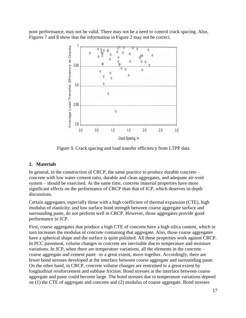
17
poor performance, may not be valid. There may not be a need to control crack spacing. Also,
Figures 7 and 8 show that the information in Figure 2 may not be correct.
Figure 9. Crack spacing and load transfer efficiency from LTPP data
2. Materials
In general, in the construction of CRCP, the same practice to produce durable concrete –
concrete with low water-cement ratio, durable and clean aggregates, and adequate air-void
system – should be exercised. At the same time, concrete material properties have more
significant effects on the performance of CRCP than that of JCP, which deserves in-depth
discussions.
Certain aggregates, especially those with a high coefficient of thermal expansion (CTE), high
modulus of elasticity, and low surface bond strength between coarse aggregate surface and
surrounding paste, do not perform well in CRCP. However, those aggregates provide good
performance in JCP.
First, coarse aggregates that produce a high CTE of concrete have a high silica content, which in
turn increases the modulus of concrete containing that aggregate. Also, those coarse aggregates
have a spherical shape and the surface is quite polished. All these properties work against CRCP.
In PCC pavement, volume changes in concrete are inevitable due to temperature and moisture
variations. In JCP, when there are temperature variations, all the elements in the concrete –
coarse aggregate and cement paste –to a great extent, move together. Accordingly, there are
fewer bond stresses developed at the interface between coarse aggregate and surrounding paste.
On the other hand, in CRCP, concrete volume changes are restrained to a great extent by
longitudinal reinforcement and subbase friction. Bond stresses at the interface between coarse
aggregate and paste could become large. The bond stresses due to temperature variations depend
on (1) the CTE of aggregate and concrete and (2) modulus of coarse aggregate. Bond stresses
18
developing in concrete containing siliceous aggregate will be larger than those in concrete with
calcareous coarse aggregate. On the other hand, concrete with coarse aggregates that have a
spherical shape and smooth surface has a lower interfacial bond strength than concrete with an
angular shape and rough texture coarse aggregates. Accordingly, concrete containing siliceous
coarse aggregates will have higher bond stress and lower strength than concrete with calcareous
coarse aggregates. As a result, the probability of severe spalling in CRCP is much higher for
concrete with siliceous coarse aggregate than concrete with calcareous coarse aggregate. Some
spalling occurred within a few years of construction, whereas some spalling occurred after as late
as 15 years after construction. Concrete with a high CTE is also more prone to horizontal
cracking at the mid-depth of the slab. Spalling and horizontal cracking due to a high CTE of
concrete should not be addressed by adjusting slab thickness. The distress mechanisms are such
that they are not well related to slab thickness.
It would be a best practice for coarse aggregates with a high CTE and modulus of elasticity to be
used in JCP, not in CRCP. In Texas, the rate of distress due to the use of those coarse aggregates
is quite high, and valuable financial resources are used to repair and rehabilitate CRCPs
constructed with them.
3. Construction
The construction of CRCP is not much different from that of other types of PCC pavement. The
major differences are the placement of steel and header joints (transverse construction joints).
Requirements for steel placement, such as staggered splice and a minimum lap length, are
stipulated in Item 360 and CRCP design standards, and no further discussions are made in this
document (TxDOT, 2004). The only construction related item that is not addressed in
specifications or design standards is the rebar pushed to the subbase in order to provide a rigidity
of the assembled steel mat. Without this rebar, a steel mat could be pushed forward when a paver
is placing concrete. Some districts require that this rebar be removed either by pulling or torching
as a paver places concrete, while other districts allow it to stay. Field evaluations of distresses in
CRCP indicate that the existence of this rebar doesn’t appear to cause distresses.
Field evaluations of punchout distress in Texas revealed that a large portion of distresses
recorded as punchouts occurred at transverse construction joints. It was also recognized that
those distresses were not caused by deficiencies in slab thickness. Figure 9 illustrates the distress
at transverse construction joints. It appears that the construction practice and quality are partially
responsible for this distress type. Since the frequency of this distress is relatively high, and
preventing this distress type will significantly improve CRCP performance in Texas, further
discussions are provided.
This type of distress occurs in relatively new CRCP where other structural distresses don’t exist,
which indicates that this distress is not related to structural capacity. There could be multiple
causes for this type of distress. The concrete supplied in this area is either the first batch of the
day or the last batch of the day. The quality of the concrete might be a little different from that of
the concrete supplied during the day. Also, the slip-form paver cannot start from the beginning of
the header joint and the concrete in this area is usually consolidated and finished by manual work,
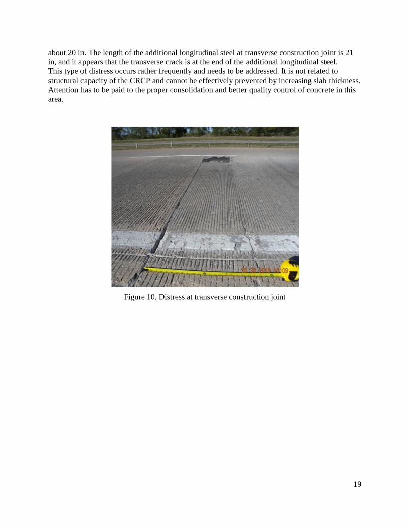
which requires concrete with a larger slump. Figure 10 shows that the width of this distress is
19
about 20 in. The length of the additional longitudinal steel at transverse construction joint is 21
in, and it appears that the transverse crack is at the end of the additional longitudinal steel.
This type of distress occurs rather frequently and needs to be addressed. It is not related to
structural capacity of the CRCP and cannot be effectively prevented by increasing slab thickness.
Attention has to be paid to the proper consolidation and better quality control of concrete in this
area.
Figure 10. Distress at transverse construction joint

20
21
REFERENCES
American Association of State Highway and Transportation Officials, (1962), “The AASHTO
Road Test,” Report 7, Summary Report, Highway Research Board Repot.
American Association of State Highway and Transportation Officials, (1980), “1972 AASHTO
Interim Guide for Design of Pavement Structures,” Washington, D.C..
American Association of State Highway and Transportation Officials, (1986), “AASHTO Guide
for the Design of Pavement Structures,” American Association of State Highway and
Transportation Officials, Washington D.C..
American Association of State Highway and Transportation Officials, (1993), “AASHTO Guide
for Design of Pavement Structures,” American Association of State Highway and Transportation
Officials, Washington, D.C..
Concrete Reinforcing Steel Institute CRSI,(2001), “Summary of CRCP Design and Construction
– Practice in the U.S”. Illinois.
ERES Consultants, (2001), “Summary of CRCP Design and Construction Practices in the U.S.,”
Research Series No 8, Concrete Reinforcing Steel Institute.
ERES, Inc., ERES Division, (2004), “Guide for Mechanistic-Empirical Design of New and
Rehabilitated Pavement Structures,” Final Report, Champaign, Illinois
Highway Research Board, (1973), “Continuously Reinforced Concrete Pavement,” National
Cooperative Highway Research Program Synthesis of Highway Practice 16, Washington D.C..
McCullough, B.F. and Ledbetter, W.B., (1960), “LTS Design of Continuously Reinforced
Concrete Pavement.” Journal of the Highway Division, Vol 86, No. HW4. Proceedings of the
American Society of Civil Engineers.
Portland Cement Association (PCA), (1984), “Thickness Design for Concrete Highway and
Street Pavements.”
22
Suh, Y.C., Hankins, K., and McCullough, B.F., (1992), “Early-Age Behavior of Continuously
Reinforced Concrete Pavement and Calibration of the Failure Prediction Model in the CRCP-7
Program,” Research Report 1244-3, Center for Transportation Research, The University of
Texas at Austin.
Taylor Crawford, James Jirsa, Megan Stringer, David Whitney and Moon Won, (2008),
“Rehabilitation Procedures for Longitudinal Cracks and Joint Separation in Concrete Pavement,”
Center for Transportation Research (CTR), The University of Texas at Austin.
TxDOT, (2004), “2004 Standard Specifications book-Concrete Pavement - Item 360,”
http://www.dot.state.tx.us/ DES/specs/2004/04srfac2.htm#360, Accessed February, 20, 2011.
Vetter, C.P., (1933), “Stresses in reinforced concrète due to volume changes,” Transactions,
American Society of Civil Engineers 98 1039–1053.
Yoder, E.J. and M.W. Witczak, (1975), “Principles of Pavement Design, Second Edition,” John
Wiley & Sons, Inc., New York, N.Y..
23
APPENDIX A
Alternative Procedure for Design of Rigid Pavement
(1972 AASHTO Interim Guide for Design of Pavement Structures)

24
25
APPENDIX B
Rigid Pavement Design Nomograph – Segment #1
(1993 AASHTO Pavement Design Guide)
26
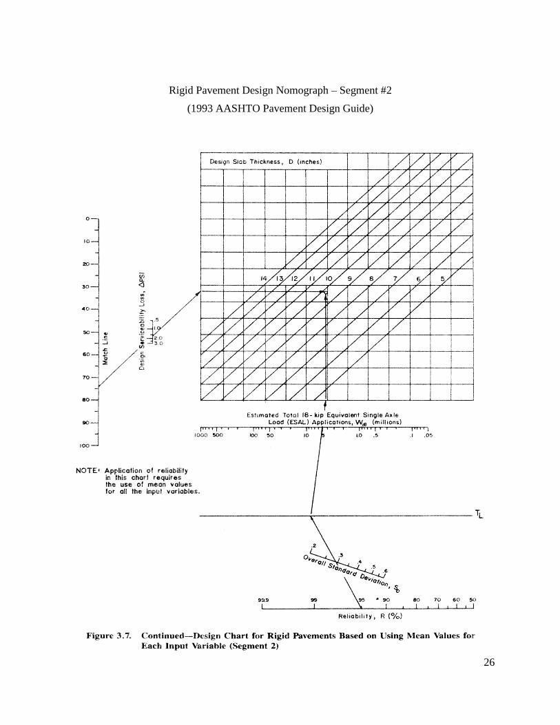
Rigid Pavement Design Nomograph – Segment #2
(1993 AASHTO Pavement Design Guide)

Multidisciplinary Research in Transportation
Soojun Ha, Jungheum Yeon, Moon C. Won
Texas Department of Transportation
CRCP ME Design Guide
Report #: 0-5832-P1www.techmrt.ttu.edu/reports.php April 2012
Multidisciplinary Research in Transportation
Texas Tech University | Lubbock, Texas 79409P 806.742.3503 | F 806.742.4168