Embed Size (px)
Citation preview

2
CRAWLER CRANE Dimensions Specifications ..................................................3 Technical Description .............................................................4 Working Ranges.....................................................................8 Rated Loads for Main Boom...................................................9 Crane Boom Construction Component Weights and Dimensions for Transport ............10 CLAMSHELL Dimensions Specifications Working Ranges Clamshell Bucket...................................12 DRAGLINE Dimensions Specifications Working Ranges Dragline Bucket .....................................13 TECHNICAL DATA Standard Equipment Front Attachments ...........................14 Standard and Optional Equipment .......................................15 Note: • All “ton” described in this catalog represent metric tons. • Specifications conform to the Safety Regulations for Cranes and Mobile
Cranes in Japan.
3
CRAWLER CRANE
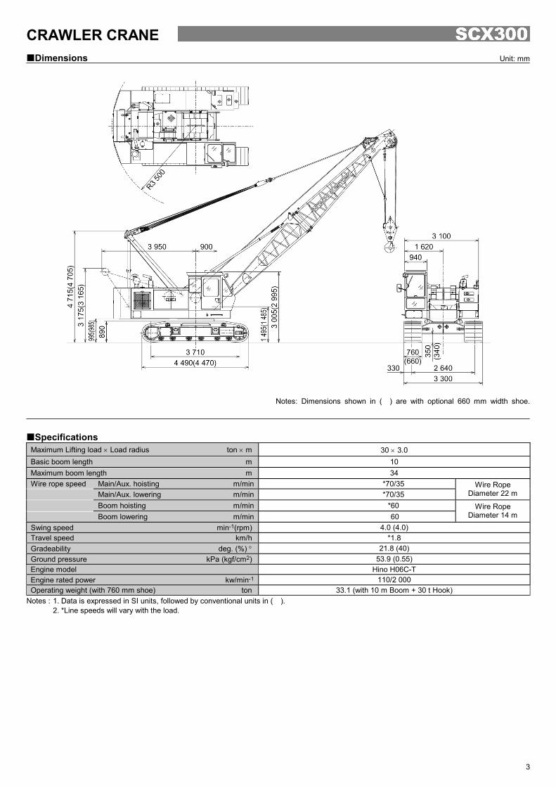
Dimensions Unit: mm
Notes: Dimensions shown in ( ) are with optional 660 mm width shoe.
Specifications Maximum Lifting load × Load radius ton × m 30 × 3.0 Basic boom length m 10 Maximum boom length m 34 Wire rope speed Main/Aux. hoisting m/min *70/35 Main/Aux. lowering m/min *70/35
Wire Rope Diameter 22 m
Boom hoisting m/min *60 Boom lowering m/min 60
Wire Rope Diameter 14 m
Swing speed min-1(rpm) 4.0 (4.0) Travel speed km/h *1.8 Gradeability deg. (%) ° 21.8 (40) Ground pressure kPa (kgf/cm2) 53.9 (0.55) Engine model Hino H06C-T Engine rated power kw/min-1 110/2 000 Operating weight (with 760 mm shoe) ton 33.1 (with 10 m Boom + 30 t Hook)
Notes : 1. Data is expressed in SI units, followed by conventional units in ( ). 2. *Line speeds will vary with the load.
4
Model ..............................Hino H06C-T Type ................................Water-cooled, 4-cycle, 6-cylinder,
direct fuel injection type diesel engine Rated power ...................110 kW (150 PS) at 2 000 min-1 (2 000 rpm) Maximum torque .............530 N⋅m (54 kgf⋅m) at 1 800 min-1
(1 800 rpm) Piston displacement .........6.845 L Fuel tank capacity ............250 L Electric system ...............DC 24 V
The SCX300 is equipped with main and auxiliary drums in-stalled on an axis. Hoisting and lowering the load is activated by forward/reverse rotation of the hydraulic motor. Power lowering is carried out with a hydraulic brake. Hoisting and lowering can be carried out at two speeds fast and slow to suit job requirements. Each drum is fitted with a friction band-type brake. This allows free fall (rapid lowering) of the bucket. Main and auxiliary hoist drums are each fitted with a pawl-type drum lock to positively hold the load in the air. The drum brake is an external contracting friction band-type using durable non-asbestos lining. The clutch is an internal expanding friction band-type using durable non-asbestos lining.
Boom hoisting/lowering is done by forward/reverse rotation of a hydraulic motor. Boom lowering is made by power lowering through a hydraulic brake. Both hydraulic brake and spring-set/hydraulic-released multi-plate disc type brake offer positive stopping of the boom. When the boom is hoisted or lowered, brakes are automatically re-leased. Boom hoist drum is fitted with a pawl-type drum lock.
Independent operation separated from other functions. Driven by a hydraulic motor through reduction gear. Swing speeds are freely controllable from zero to maximum speed with a single lever.
Swing Brake The disc-type swing brake can be hydraulically applied by the brake switch on the swing lever. Swing Lock Manual mechanical-lock with a rod tip engaged in the holder of the track frame for transportation. Swing Circle Single-row shear-type ball bearing with heat-treated internal gear.
All welded steel construction, stress-relieved, precision- machined for rigidity and strength. Gantry Lowerable for transportation. Counterweight Total weight: 8 800 kg
Superstructure
Engine
Main and Auxiliary Hoist Mechanism
Boom Hoist Mechanism
Swing Mechanism
Revolving Frame
5
Angle Chord Crane Boom 935 mm wide by 935 mm deep at connection, lattice construction using high-tensile steel angle chords. Basic boom ..............Total length 10.0 m, 2-piece construction;
upper section 5.0 m and lower section 5.0 m. Boom point ...............Offset boom point, 3 sheaves (462 mm
PCD) mounted on anti-friction bearings on boom top.
Boom inserts ............3.0 m and 6.0 m long available. Connection type .......Pin-connected. Boom backstop ........Dual-rail, telescopic tubular construction
with spring damper. Boom hoist bridle .....Serves as connection between pendants
and boom hoist wire rope reeving, equipped with 6 sheaves (300 mm PCD) for 12-part boom hoist wire rope reeving.
All-weather, well-ventilated, roomy operator's cab with good visi-bility. The independent cab is insulated against noise and vibra-tion. Sliding, fold-in front window swings up and stores in roof.
2 variable displacement piston pumps allow both independent and combined operations of all functions. Variable displacement piston pumps control working speeds, and make effective use of engine horsepower.
Pump-1 Pump-2 Type of pump Variable displacement
Pressure setting 27.4 MPa (280 kgf/cm2)
27.4 MPa (280 kgf/cm2)
Max. oil flow* 200 L/min 200 L/min Pump-3 Pump-4 Type of pump Gear Gear
Pressure setting 20.6 MPa (210 kgf/cm2)
4.4 MPa (45 kgf/cm2)
Max. oil flow* 134 L/min 32 L/min *with non-loaded condition Main and Auxiliary Hoist Motors (Common Motor) Axial piston motors with counterbalance valves. Boom Hoist Motor Axial piston motor with counterbalance valve. Swing Motor Axial piston motor. Travel Motors Axial piston motors with brake valve and spring-set/hydraulic- released multiplate disc brake Relief and Brake Valves
Each hydraulic circuit incorporates large-capacity relief valves to protect circuit from overload and shock load. Counterbalance valves, provided for hoist motor, compensate load lowering and prevent accidental load drop if hydraulic power is suddenly reduced. Brake valves (consisting of relief valve and counterbalance valve) are provided for travel circuit.
Pressure Settings Main Circuit
Main relief valves Hoist (main and aux.) ......................... 27.4 MPa (280 kgf/cm2) Swing.................................................. 20.6 MPa (210 kgf/cm2) Overload relief valves Hoist (main and aux.) circuits ............. 28.1 MPa (287 kgf/cm2) Boom hoist circuit ............................... 25.9 MPa (265 kgf/cm2) Travel circuit ....................................... 31.8 MPa (325 kgf/cm2)
Pilot Circuit Main relief valve ............................................................... 4.4 MPa (45 kgf/cm2)
Line Filters High-filtration 10 µm full-flow filter element is incorporated in the return line. Pilot filter and suction filter are provided in each circuit.
Boom
Operator's Cab
HYDRAULIC SYSTEM
6
Traction mechanism
Each track is driven by an axial piston motor through reduction gear. This mechanism allows counter-rotation of tracks for maneuverability in close quarters. When the lever is in neutral position, both hydraulic brake and spring-set/hydraulic-released multiplate disc brake are auto-matically applied for stopping.
Track Frame All-welded, stress-relieved, box-section construction Side Frames Side frames of all-welded robust rolled steel, stress relieved, box section construction. Track Shoes Heat-treated alloy steel castings with induction-hardened roller path and driving lugs. No. of upper rollers (each side) ........................2 No. of lower rollers (each side).........................6 No. of track shoes (each side) .......................53 Shoe width.............................................760 mm Optional shoe width...............................660 mm Boom, Main and Auxiliary Hoist, Swing and Travel Remote controlled hydraulic servo. Working speed can be pre-cisely controlled according to lever stroke.
Monitor Telling Machine Conditions With the monitor, the operator can check, at a glance, engine
oil pressure, water temperature and fuel level, as well as levels of hydraulic oil, engine oil and coolant. The red light turns on and/or the buzzer sounds in the event of an abnormality.
Boom Angle Indicator Mechanical-type boom angle indicator is provided at boom foot. Counterbalance Valves (Brake Valves) Counterbalance valves are each incorporated in travel motors, boom hoist motor, and main and auxiliary hoist motor. If the hy-draulic line is broken, this valve is automatically actuated to pre-vent motor rotation. Spring-Set/Hydraulic-Released Multiplate Disc Type Travel Brakes Swing Lock and Swing Parking Brake Drum Locks A pawl-type drum lock is adopted for main drum, auxiliary drum and boom drum. Lever Locks Main and auxiliary clutch levers are each fitted with lock mecha-nisms to prevent mishandling. Devices for Crane Operation
Moment Limiter The “Hi-Limiter” electrically detects the lifting load, and working
radius from the boom angle. The detected data is calculated by a built-in microcomputer. When the lifting load reaches its alarm limit the “Hi-Limiter” buzzers, and when reaching the load limit, the control becomes inoperative.
Hook Overhoist Prevention Device
When the hook reaches its hoist limit, the bell sounds and the auto-stop automatically actuates at the same time.
Boom Overhoist Prevention Device
When the boom reaches its angle limit, the buzzer alarm sounds and boom hoisting automatically stops at the same time. The telescopic-type boom backstop is also provided.
Secondary Boom Overhoist Prevention Device
In addition to the hook overhoist prevention device and boom overhoist prevention device, the secondary boom overhoist prevention device is provided.
Reliable mechanism
The related movements stop automatically if an electric wire is broken.
Undercarriage
Controls
Safety Device
7
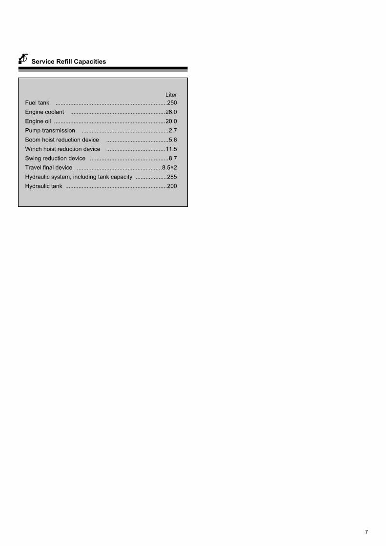
LiterFuel tank ....................................................................250Engine coolant ..........................................................26.0Engine oil ....................................................................20.0Pump transmission .....................................................2.7Boom hoist reduction device ......................................5.6Winch hoist reduction device ....................................11.5Swing reduction device ................................................8.7Travel final device ....................................................8.5×2Hydraulic system, including tank capacity ...................285Hydraulic tank ..............................................................200
Service Refill Capacities
8
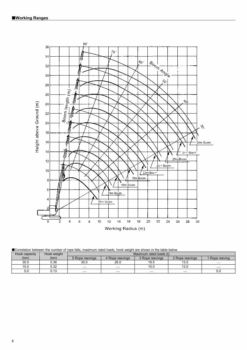
Working Ranges
Correlation between the number of rope falls, maximum rated loads, hook weight are shown in the table below. Maximum rated loads (t) Hook capacity
(ton) Hook weight
(ton) 5 Rope reevings 4 Rope reevings 3 Rope reevings 2 Rope reevings 1 Rope reeving 30.0 0.36 30.0 26.0 19.5 13.0 15.0 0.32 15.0 13.0 5.0 0.13 5.0
9
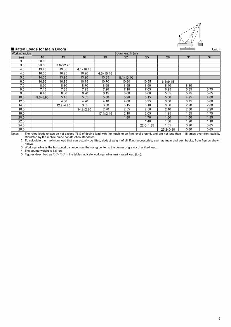
Rated Loads for Main Boom Unit: t Working radius Boom length (m)
(m) 10 13 16 19 22 25 28 31 34 3.0 30.00 3.5 23.85 3.6×22.70 4.0 19.40 19.35 4.1×18.45 4.5 16.30 16.25 16.20 4.6×15.45 5.0 14.05 13.95 13.90 13.85 5.1×13.40 6.0 10.95 10.85 10.75 10.70 10.60 10.55 6.5×9.45 7.0 8.90 8.80 8.70 8.65 8.55 8.50 8.40 8.30 8.0 7.45 7.35 7.25 7.20 7.10 7.05 6.95 6.85 6.75 9.0 6.40 6.30 6.20 6.15 6.00 6.00 5.85 5.75 5.65 10.0 9.6×5.90 5.45 5.35 5.30 5.20 5.15 5.00 4.95 4.80 12.0 4.30 4.20 4.10 4.00 3.95 3.80 3.75 3.60 14.0 12.2×4.25 3.35 3.30 3.15 3.10 3.00 2.90 2.80 16.0 14.8×2.90 2.70 2.55 2.50 2.40 2.30 2.20 18.0 17.4×2.45 2.10 2.05 1.95 1.85 1.75 20.0 1.80 1.70 1.60 1.50 1.35 22.0 1.40 1.30 1.20 1.10 24.0 22.6×1.35 1.05 0.96 0.85 26.0 25.2×0.90 0.80 0.65
Notes: 1. The rated loads shown do not exceed 78% of tipping load with the machine on firm level ground, and are not less than 1.15 times over-front stability stipulated by the mobile crane construction standards.
2. To calculate the maximum load that can actually be lifted, deduct weight of all lifting accessories, such as main and aux. hooks, from figures shown above.
3. Working radius is the horizontal distance from the swing center to the center of gravity of a lifted load. 4. The counterweight is 8.8 ton. 5. Figures described as × in the tables indicate working radius (m) × rated load (ton).
10
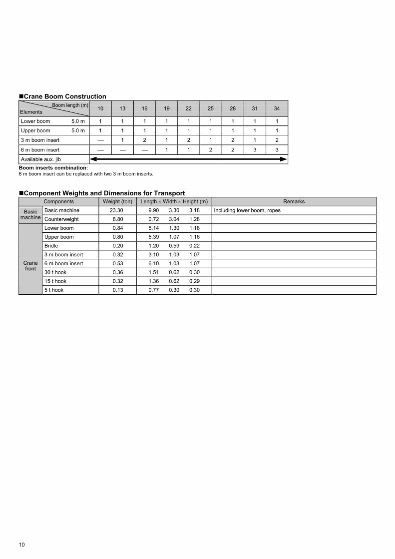
Crane Boom Construction Boom length (m)
Elements 10 13 16 19 22 25 28 31 34
Lower boom 5.0 m 1 1 1 1 1 1 1 1 1
Upper boom 5.0 m 1 1 1 1 1 1 1 1 1
3 m boom insert 1 2 1 2 1 2 1 2
6 m boom insert 1 1 2 2 3 3
Available aux. jib Boom inserts combination: 6 m boom insert can be replaced with two 3 m boom inserts.
Component Weights and Dimensions for Transport Components Weight (ton) Length × Width × Height (m) Remarks Basic machine 23.30 9.90 3.30 3.18 Including lower boom, ropes Basic
machine Counterweight 8.80 0.72 3.04 1.28 Lower boom 0.84 5.14 1.30 1.18 Upper boom 0.80 5.39 1.07 1.16 Bridle 0.20 1.20 0.59 0.22 3 m boom insert 0.32 3.10 1.03 1.07 6 m boom insert 0.53 6.10 1.03 1.07 30 t hook 0.36 1.51 0.62 0.30 15 t hook 0.32 1.36 0.62 0.29
Crane front
5 t hook 0.13 0.77 0.30 0.30

11
MEMO
12
CLAMSHELL
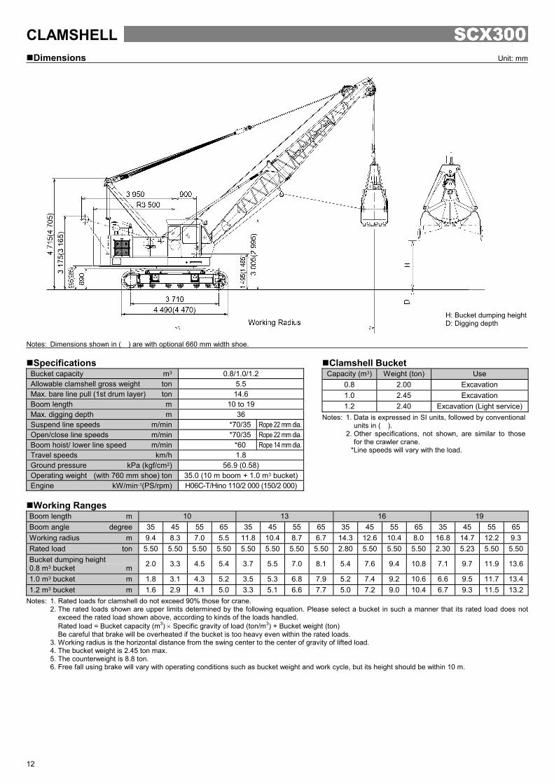
Dimensions Unit: mm
Notes: Dimensions shown in ( ) are with optional 660 mm width shoe.
Specifications Bucket capacity m3 0.8/1.0/1.2 Allowable clamshell gross weight ton 5.5 Max. bare line pull (1st drum layer) ton 14.6 Boom length m 10 to 19 Max. digging depth m 36 Suspend line speeds m/min *70/35 Rope 22 mm dia.Open/close line speeds m/min *70/35 Rope 22 mm dia.Boom hoist/ lower line speed m/min *60 Rope 14 mm dia.Travel speeds km/h 1.8 Ground pressure kPa (kgf/cm2) 56.9 (0.58) Operating weight (with 760 mm shoe) ton 35.0 (10 m boom + 1.0 m3 bucket)Engine kW/min-1(PS/rpm) H06C-T/Hino 110/2 000 (150/2 000)
Working Ranges
Boom length m 10 13 16 19 Boom angle degree 35 45 55 65 35 45 55 65 35 45 55 65 35 45 55 65Working radius m 9.4 8.3 7.0 5.5 11.8 10.4 8.7 6.7 14.3 12.6 10.4 8.0 16.8 14.7 12.2 9.3Rated load ton 5.50 5.50 5.50 5.50 5.50 5.50 5.50 5.50 2.80 5.50 5.50 5.50 2.30 5.23 5.50 5.50Bucket dumping height 0.8 m3 bucket m 2.0 3.3 4.5 5.4 3.7 5.5 7.0 8.1 5.4 7.6 9.4 10.8 7.1 9.7 11.9 13.6
1.0 m3 bucket m 1.8 3.1 4.3 5.2 3.5 5.3 6.8 7.9 5.2 7.4 9.2 10.6 6.6 9.5 11.7 13.41.2 m3 bucket m 1.6 2.9 4.1 5.0 3.3 5.1 6.6 7.7 5.0 7.2 9.0 10.4 6.7 9.3 11.5 13.2
Notes: 1. Rated loads for clamshell do not exceed 90% those for crane. 2. The rated loads shown are upper limits determined by the following equation. Please select a bucket in such a manner that its rated load does not
exceed the rated load shown above, according to kinds of the loads handled. Rated load = Bucket capacity (m3) × Specific gravity of load (ton/m3) + Bucket weight (ton) Be careful that brake will be overheated if the bucket is too heavy even within the rated loads.
3. Working radius is the horizontal distance from the swing center to the center of gravity of lifted load. 4. The bucket weight is 2.45 ton max. 5. The counterweight is 8.8 ton. 6. Free fall using brake will vary with operating conditions such as bucket weight and work cycle, but its height should be within 10 m.
Clamshell Bucket Capacity (m3) Weight (ton) Use
0.8 2.00 Excavation 1.0 2.45 Excavation 1.2 2.40 Excavation (Light service)
Notes: 1. Data is expressed in SI units, followed by conventional units in ( ).
2. Other specifications, not shown, are similar to those for the crawler crane.
*Line speeds will vary with the load.
H: Bucket dumping height D: Digging depth
13
DRAGLINE
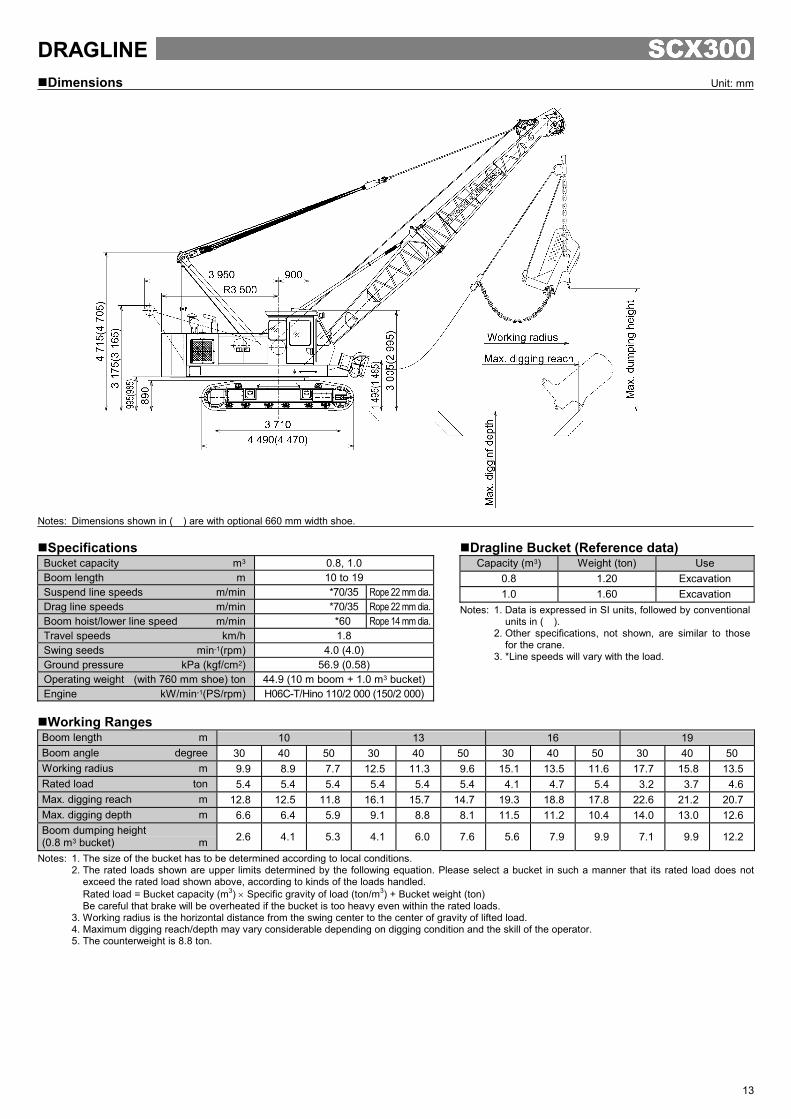
Dimensions Unit: mm
Notes: Dimensions shown in ( ) are with optional 660 mm width shoe.
Specifications Bucket capacity m3 0.8, 1.0 Boom length m 10 to 19 Suspend line speeds m/min *70/35 Rope 22 mm dia.Drag line speeds m/min *70/35 Rope 22 mm dia.Boom hoist/lower line speed m/min *60 Rope 14 mm dia.Travel speeds km/h 1.8 Swing seeds min-1(rpm) 4.0 (4.0) Ground pressure kPa (kgf/cm2) 56.9 (0.58) Operating weight (with 760 mm shoe) ton 44.9 (10 m boom + 1.0 m3 bucket)Engine kW/min-1(PS/rpm) H06C-T/Hino 110/2 000 (150/2 000)
Working Ranges
Boom length m 10 13 16 19 Boom angle degree 30 40 50 30 40 50 30 40 50 30 40 50 Working radius m 9.9 8.9 7.7 12.5 11.3 9.6 15.1 13.5 11.6 17.7 15.8 13.5Rated load ton 5.4 5.4 5.4 5.4 5.4 5.4 4.1 4.7 5.4 3.2 3.7 4.6Max. digging reach m 12.8 12.5 11.8 16.1 15.7 14.7 19.3 18.8 17.8 22.6 21.2 20.7Max. digging depth m 6.6 6.4 5.9 9.1 8.8 8.1 11.5 11.2 10.4 14.0 13.0 12.6Boom dumping height (0.8 m3 bucket) m 2.6 4.1 5.3 4.1 6.0 7.6 5.6 7.9 9.9 7.1 9.9 12.2
Notes: 1. The size of the bucket has to be determined according to local conditions. 2. The rated loads shown are upper limits determined by the following equation. Please select a bucket in such a manner that its rated load does not
exceed the rated load shown above, according to kinds of the loads handled. Rated load = Bucket capacity (m3) × Specific gravity of load (ton/m3) + Bucket weight (ton) Be careful that brake will be overheated if the bucket is too heavy even within the rated loads.
3. Working radius is the horizontal distance from the swing center to the center of gravity of lifted load. 4. Maximum digging reach/depth may vary considerable depending on digging condition and the skill of the operator. 5. The counterweight is 8.8 ton.
Dragline Bucket (Reference data) Capacity (m3) Weight (ton) Use
0.8 1.20 Excavation 1.0 1.60 Excavation
Notes: 1. Data is expressed in SI units, followed by conventional units in ( ).
2. Other specifications, not shown, are similar to those for the crane.
3. *Line speeds will vary with the load.
14
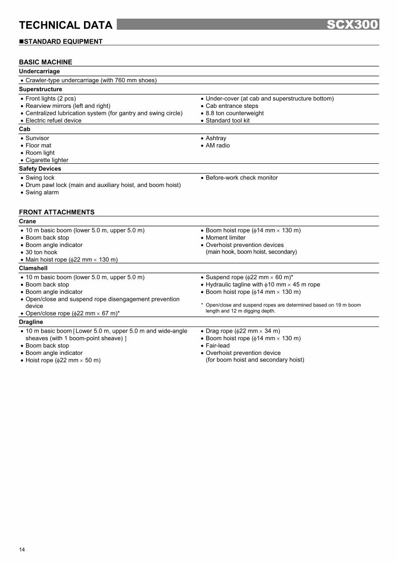
TECHNICAL DATA
STANDARD EQUIPMENT BASIC MACHINE Undercarriage • Crawler-type undercarriage (with 760 mm shoes)
Superstructure • Front lights (2 pcs) • Rearview mirrors (left and right) • Centralized lubrication system (for gantry and swing circle) • Electric refuel device
• Under-cover (at cab and superstructure bottom) • Cab entrance steps • 8.8 ton counterweight • Standard tool kit
Cab • Sunvisor • Floor mat • Room light • Cigarette lighter
• Ashtray • AM radio
Safety Devices • Swing lock • Drum pawl lock (main and auxiliary hoist, and boom hoist) • Swing alarm
• Before-work check monitor
FRONT ATTACHMENTS Crane • 10 m basic boom (lower 5.0 m, upper 5.0 m) • Boom back stop • Boom angle indicator • 30 ton hook • Main hoist rope (φ22 mm × 130 m)
• Boom hoist rope (φ14 mm × 130 m) • Moment limiter • Overhoist prevention devices
(main hook, boom hoist, secondary)
Clamshell • 10 m basic boom (lower 5.0 m, upper 5.0 m) • Boom back stop • Boom angle indicator • Open/close and suspend rope disengagement prevention
device • Open/close rope (φ22 mm × 67 m)*
• Suspend rope (φ22 mm × 60 m)* • Hydraulic tagline with φ10 mm × 45 m rope • Boom hoist rope (φ14 mm × 130 m) * Open/close and suspend ropes are determined based on 19 m boom
length and 12 m digging depth.
Dragline • 10 m basic boom [Lower 5.0 m, upper 5.0 m and wide-angle
sheaves (with 1 boom-point sheave) ] • Boom back stop • Boom angle indicator • Hoist rope (φ22 mm × 50 m)
• Drag rope (φ22 mm × 34 m) • Boom hoist rope (φ14 mm × 130 m) • Fair-lead • Overhoist prevention device
(for boom hoist and secondary hoist)
15
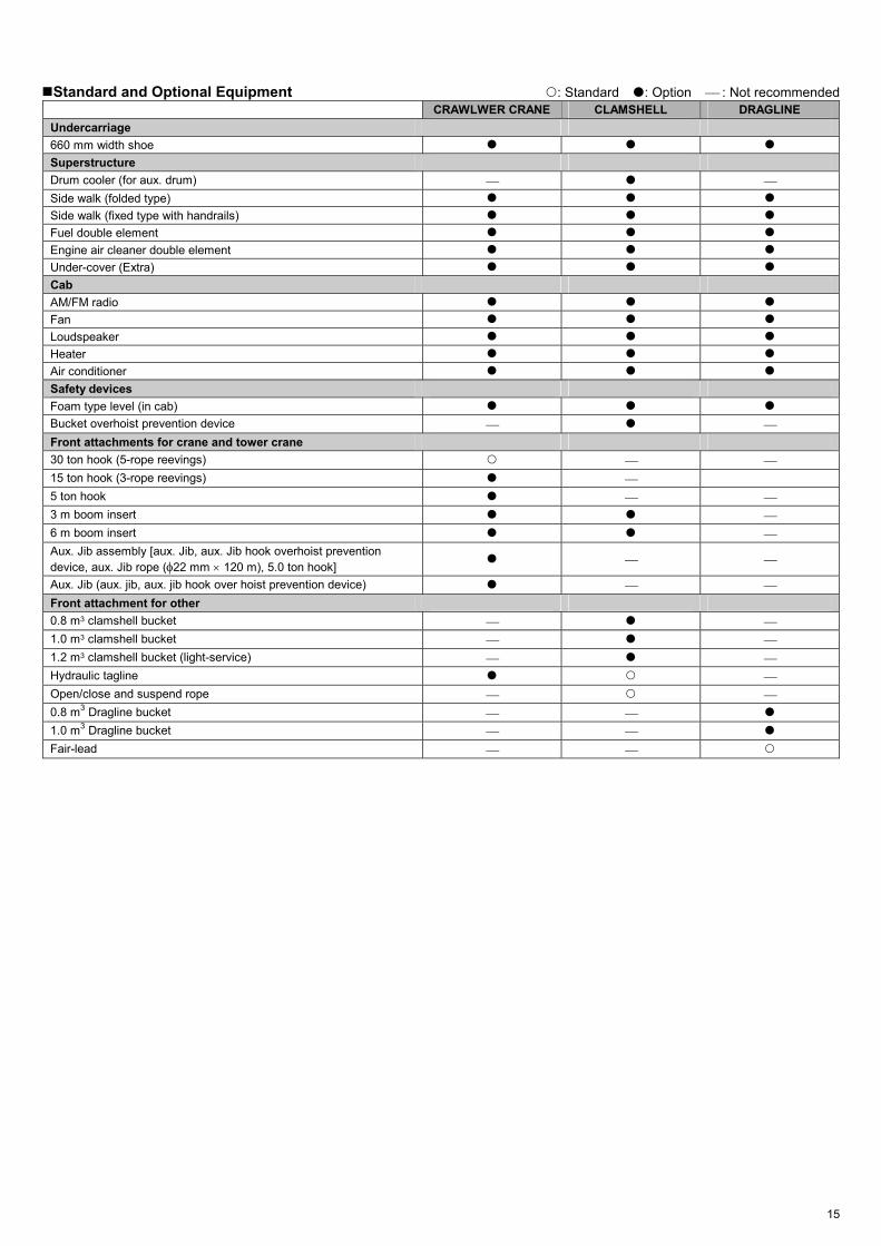
Standard and Optional Equipment : Standard : Option : Not recommended CRAWLWER CRANE CLAMSHELL DRAGLINE Undercarriage 660 mm width shoe Superstructure Drum cooler (for aux. drum) Side walk (folded type) Side walk (fixed type with handrails) Fuel double element Engine air cleaner double element Under-cover (Extra) Cab AM/FM radio Fan Loudspeaker Heater Air conditioner Safety devices Foam type level (in cab) Bucket overhoist prevention device Front attachments for crane and tower crane 30 ton hook (5-rope reevings) 15 ton hook (3-rope reevings) 5 ton hook 3 m boom insert 6 m boom insert Aux. Jib assembly [aux. Jib, aux. Jib hook overhoist prevention device, aux. Jib rope (φ22 mm × 120 m), 5.0 ton hook]
Aux. Jib (aux. jib, aux. jib hook over hoist prevention device) Front attachment for other 0.8 m3 clamshell bucket 1.0 m3 clamshell bucket 1.2 m3 clamshell bucket (light-service) Hydraulic tagline Open/close and suspend rope 0.8 m3 Dragline bucket 1.0 m3 Dragline bucket Fair-lead

This catalog is not applicable to European and North America areas.The machine shown may vary according to territory Specifications.
Hitachi Sumitomo Heavy Industries Construction Cranes Co.,Ltd
Head Office : 12-14 Ueno 7-chome, Taito-ku, Tokyo 110-005, Japan Telephone : (03)3845-1386 Facsimile : (03)3845-1394 http://www.hands-crane.com
KC-E156 Printed in Japan. 02.10 (KA/KA, FT3)