Embed Size (px)
Citation preview
1. Report No. 2. Government Accession No.
TTI-2-10-75-223-1 4. Title and Subtitle
Crash Test and Evaluation of a Precast Concrete Median Barrier
7. Author's)
T. J. Hirsch and E. L. Marquis
9. Performing Organization Nome and Address
Texas Transportation Institute Texas A&M University College Station, ·Texas 77840
TECHNICAL REPORT STANDARD TITLE PACE"
3. Recipient's Catalog No.
5. Report Date
October 1975 6. Performing Organization Code
8. Performing Organization Report No.
Research Report No. 223-1 10. Work Unit No.
11. Contract or Grant No.
Study No. 2-10-75-223 13. Type of Report and Period Covered
~~----~--~~--~~------------------------~ 12. Sponsoring ·Agency Nome and Address
Texas State Department of Highways and Public Transportation; Transportation Planning Division
Interim _ September, 1974 October, 1975
14. Sponsoring Agency Code P. O. Box 5051 Allc:tin T~'\(~c: 7P.7h?.
15. Supplementary Notes
Research done in cooperation with DOT, FHWA. Study Title: "Crash Test and Evaluation of Precast Concrete Barrier and Remedial
Measures for Crash Cushionc:" 16. Abstroct
Median barriers are used on high-volume, high-speed traffic facilities to preven errant vehicles from crossing a median and conflicting with the opposing traffic stream. A secondary function for some designs of median barriers is to minimize the glare of opposing headlights.
The cast-in-place Concrete Median Barrier (CMB) has proven to be an effective and economical barrier in Texas and other states. Investigation into the use of a precast concretemed ian barri er ·stemmed from the interest i nvo 1 ved in utili zing a barrier to be prefabricated concurrently with roadway construction. This more effective utilization of work force as well as early project completion and acceptance coYld provide measurable potential savings to both contractor and the State. In addition, when this barrier is installed on existing facilities the traffic may be disrupted for a considerable period of time if it is cast-in-place. Consequently, there is a need for a Precast Concrete Median Barrier CPCMB) which can be quickly installed on active facilities with a minimum period of traffic disruption.
In order for a precast concrete median barrier to function properly in redirecting vehicles, the relatively short precast sections must be adequately connected together after they are placed in the highway median.
. Engineers of the Texas State Department of Highways and Public Transportation and the Texas Transportation Institute developed working drawings for precast section of a PCMB and two connection details. Full-scale crash tests were conducted on the PCMB and connections in order to verify the stability and strength of the installatio
17. Key Word.
Concrete (Precast), Crash Tests, Highway Safety Median Barriers, Impact, Traffic Barriers.
18. Distribution Statement
No Restrictions. This document is available to the public through the National Technica1 Information Service, Springfield, Virginia 22161.
19. Security Clossif. (of this report) 20. Security Classif. (of this poge) 21. No. of Page. 22. Price
Unclassified Unc1assified 48
Form DOT F 1700.7 (e·69)
CRASH TEST AND EVALUATION OF A PRECAST CONCRETE MEDIAN BARRIER
by
T. J. Hirsch Research Engineer
and
E. L. Marqui s Assistant Research Engineer
Research Report 223-1 Crash Test and Evaluation of Precast
Concrete Barrier and Remedial Measures for Crash Cushions
Research Study Number 2-10-75-223
Sponsored by The State Department of Highways
and Public Transportation . in cooperation with
The United States Department of Transportation Federal Highway Administration
October 1975
Texas Transportation Institute Texas A&M University
College Station, Texas 77843
DISCLAIMER
The contents of this report reflect the views of the authors who
are responsible for the facts and the accuracy of the data presented
herein. The contents do not necessarily reflect the official views
or policies of the Federal Highway Administration. This report does
not constitute a standard, specification, or regulation.
KEY WORDS
Concrete (Precast), Crash Tests, Highway Safety Median Barriers,
Impact, Traffic Barriers.
i i
ACKNOWLEDGEMENTS
This study was conducted under a cooperative program between the
Texas Transportation Institute and the Texas State Department of Highways
and Public Transportation. It was sponsored by the Texas State Department
of Highways and Public Transportation and the Federal Highway Administration.
Liaison was maintained through Mr. John F. Nixon of the Texas State Department
of Highways and Public Transportation. The crash tests and evaluation were
carried out by personnel of the Highway Safety Research Center of the Texas
Transportation Institute.
iii
L-________________________________________________________ _ ___ _
ABSTRACT
Median barriers are used on high-volume, high-speed traffic facilities
to prevent errant vehicles from crossing a median and conflicting with the
opposing traffic stream. A secondary function for some designs of median
barriers is to minimize the glare of opposing headlights.
The cast-in~place Concrete Median Barrier (CMB) has proven to be an
effective and economical barrier in Texas and other states. Investigation
into the use of a precast concrete median barrier stemmed from the interest
involved in utilizing a barrier to be prefabricated concurrently with road
way construction. This more effective utilization of work force as well as
early project completion and acceptance could provide measurable potential
savings to both contractor and the State. In addition, when this barrier
is installed on existing facilities the traffic may be disrupted for a
considerable period of time if itis cast-in-place. Consequently, there is
a need for a Precast Concrete Median Barrier (PCMB) which can be quickly
installed on active facilities with a minimum period of traffic disruption.
In order for a precast concrete median barrier to function properly
in redirecting vehicles, the relatively short precast sections must be
adequately connected together after they are placed in the highway median.
Engineers of the Texas State Department of Highways and Public Trans
portation and the Texas Transportation Institute developed working
drawings for precast sections of a PCMB and two connection details.
Full-scale crash tests were conducted on the PCMB and connections in
order to verify the stability and strength of the installation.
iv
IMPLEMENTATION STATEMENT
Median barriers are used on high-volume, high-speed traffic facilities
to prevent errant vehicles from crossing a median and conflicting with the
opposing traffic stream. A secondary function for some designs of median
barriers is to minimize the glare of'~pposing headlights.
The cast-in-place Concrete Median Barrier (CMB) has proven to be an
effective and economical barrier in Texas and other states. Investigation
into the use of a precast concrete median barrier stemmed from the interest
involved in utilizing a barrier to be prefabricated concurrently with
roadway construction. This more effective utilization of work force as well
as early project completion and acceptance could provide measurable potential
savings to both contractor and the State. Sections of a PCMB can also be used
as a temporary barrier during construction of a new facility since the pre
cast sections are portable and can be moved after the need no longer exists.
In order for a precast concrete median barrier to function properly in
redirecting vehicles, the relatively short precast sections must be
adequately connected together after they are placed in the desired location.
Engineers of the Texas State Department of Highways and Public Trans
portation and the Texas Transportation Institute developed working drawings
for 30 ft (9.1 m) long precast sections of a PCMB and two connection details.
Three sections of the PCMB were precast, hauled to the Texas A&M University
Research Annex and installed using two different connection details. Full
scale crash tests were conducted on each of the connections developed in order
to verify the stability and the strength of the installation. Both tests
were successful with the vehicles being smoothly redirected.
The PCMB developed is now being used on IH 35 in Austin, Texas. De
sign details of the PCMB can be obtained from the Texas State Department of
Highways and Public Transportation in Austin, Texas.
v
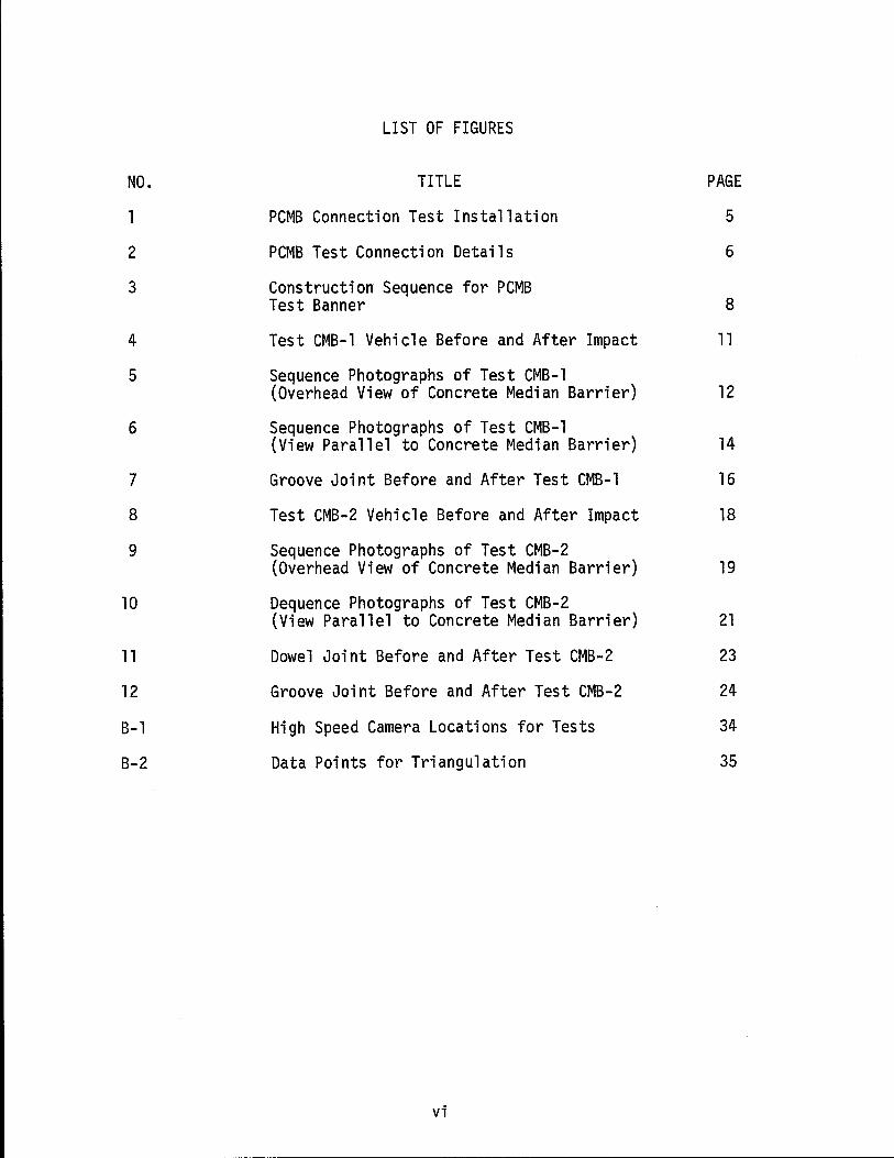
LIST OF FIGURES
NO. TITLE PAGE
1 PCMB Connection Test Installation 5
2 PCMB Test Connection Details 6
3 Construction Sequence for PCMB Test Banner 8
4 Test CMB-1 Vehicle Before and After Impact 11
5 Sequence Photographs of Test CMB-l (Overhead View of Concrete Median Barrier) 12
6 Sequence Photographs of Test CMB-l (View Parallel to Concrete Median Barrier) 14
7 Groove Joint Before and After Test CMB-1 16
8 Test CMB-2 Vehicle Before and After Impact 18
9 Sequence Photographs of Test CMB-2 (Overhead View of Concrete Median Barrier) 19
10 Dequence Photographs of Test CMB-2 (View Parallel to Concrete Median Barrier) 21
11 Dowel Joint Before and After Test CMB-2 23
12 Groove Joint Before and After Test CMB-2 24
B-1 High Speed Camera Locations for Tests 34
B-2 Data Points for Triangulation 35
vi
--- ------------------------------------------
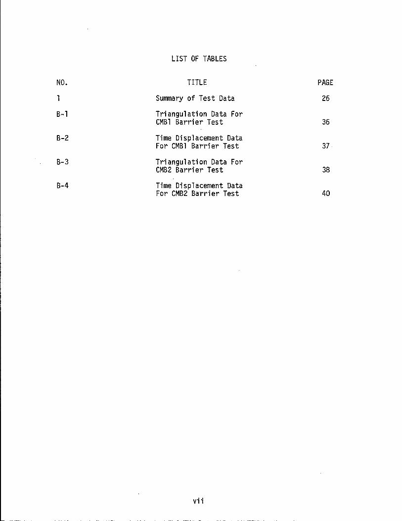
LIST OF TABLES
NO. TITLE PAGE
1 Summary of Test Data 26
B-1 Triangulation Data For CMBl Barrier Test 36
B-2 Time Displacement Data For CMBl Barrier Test 37
B-3 Triangulation Data For CMB2 Barrier Test 38
B-4 Time Displacement Data For CMB2 Barrier Test 40
vii
DISCLAIMER . • .
ACKNOWLEDGEMENTS
ABSTRACT . . . .
IMPLEMENTATION STATEMENT
LIST OF FIGURES
LIST OF TABLES
TABLE OF CONTENTS
;;
. ;;; ;v
v
v;
v;;
INTRODUCTION . 1
DESIGN AND INSTALLATION OF THE PRECAST CONCRETE MEDIAN BARRIER 3
(1) DESIGN ....
(2) INSTALLATION
VEHICLE CRASH TESTS
TEST 1
TEST 2 .
DISCUSSION OF TESTS
CONCLUSIONS
REFERENCES
APPENDIX A - STRESS ANALYSIS
APPENDIX B - INSTRUMENTATION
v;;;
. . .
. . .
3
7
10
10
10
25
27
28
29
32
INTRODUCTION
Median barriers are used on high-volume, high-speed traffic facilities
to prevent errant vehicles from crossing a median and conflicting with the
opposing traffic stream. Current warrants proposed by NCHRP for the instal-
lation of median barriers are based on a 2-year traffic projection and
the median width (1). Typically the warrants state that for a median width
of 20 ft (6.1 m) or less and a predicted ADT (Average Daily Traffic) of
20,000 or more a median barrier should be installed. Facilities with less
traffic than this frequently do not have median barriers. If the ADT in
creases to 20,000 or more it will frequently become necessary to install
a median barrier on an existing facility.
Texas median barrier warrants (~) are based on the width of the
median. Briefly, the Texas warrants require that for medians up to
24 ft in width a concrete barrier should be used. For medians from 18
to 24 ft in width either the concrete or the double steel beam type should
be used. For medians from 24 to 30 ft the double steel beam type should be
used.
The cast-in-place Concrete Median Barrier (CMB) has proven to be an
effective and economical barrier in Texas and other states. Investigation
into the use of a precast concrete median barrier stemmed from the in
terest involved in utilizing a barrier to be prefabricated concurrently with
roadway construction. This more effective utilization of work force as
well as early project completion and acceptance could provide measurable
potential savings to both contractor and the State. However, when this
barrier is installed on existing facilities the traffic may be disrupted
for a considerable period of time if it is cast-in-place. Consequently,
1
there is a need for a Precast Concrete Median Barrier (PCMB) which can be
quickly installed on active facilities with a minimum period of traffic
disruption. In addition, sections of a PCMB can also be used as a temp
orary barrier during construction of a new facility since the precast
sections are portable and can be moved after the need no longer exists.
In order for a PCMB to function properly in redirecting a vehicle, the
relative short precast sections must be adequately connected together
after they are placed in the desired location. Engineers of the Texas
State Department of Highways and Public Transportation (SDHPT) and the
Texas Transportation Institute (TTl) developed working drawings for
30 ft (9.1 m) long precast concrete sections of a PCMB and two different
connection details.
Three sections of the PCMB were precast, hauled to the Texas A&M
University Research Annex and installed using the two different connection
details. Full scale crash tests were conducted on each of the connections
in order to verify the stability and the strength of the installation.
2
DESIGN AND INSTALLATION
Design
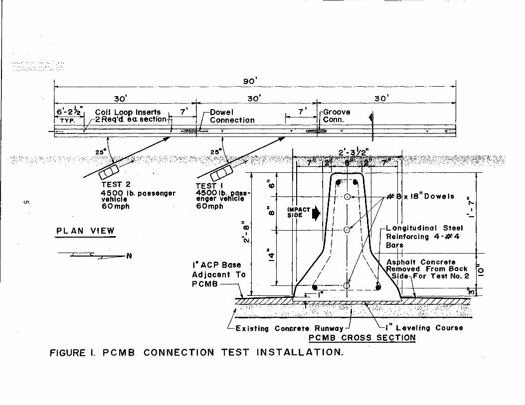
The cross-section used for the PCMB is shown by Figure 1. This
shape is standard in Texas and is essentially the "New Jersey" cross
section with minor modifications.
The concrete median barrier of the New Jersey cross-section has
been extensively tested to determine the adequacy of the shape and
redirection capabilities. Since that time the CMB has been subjected
to testing by numerous organizations including the TTI(1, i, ~). These
reports attested to the sufficiency of the CMB particularly for narrow
medians and shallow impact angles. In all of the successful tests the
CMB was attached to a simulated bridge parapet (1) or the barrier was
long, massive and rigid.
The SDHPT has used precast CMB sections on bridges for some time.
These precast sections varied from 15 ft (4.5 m) to 30 ft (9.1 m) in
length and were rigidly attached to the bridge deck with anchor bolts
at 2 ft (0.6 m) maximum spacing.
California had tested twelve 12 1/2 ft (3.8 m) long precast sections
of approximately 5000 lbm (2270 kg) each, and pinned together with a steel
rod inserted into eye bolts cast in the ends of the sections to form a
150 ft (45.7 m) barrier free standing on asphaltic concrete (~). Two tests
were conducted with a 4800 lbm (2177 kg) vehicle at a nominal speed of 65
mph (104.6 kph). In the first test, which was moderately successful, the
vehicle impacted the barrier at 7 degrees. The second test was at a 25
degree impact angle and was less than successful. The barrier rotated
and displaced laterally and the vehicle snagged. A second barrier of
3
five 20 ft (6.1 m) sections of approximately 8000 1bm (3630 kg) was
constructed and tested at 65 mph (104.6 kph) and 35 degrees, i.e.
more than the normal 25 degrees. This test was even less successful
than Test No.2. The barrier segments rotated, displaced laterally
and the vehicle rolled over.
In view of the California experience engineers with the Texas
SDHPT elected to test precast sections 30 ft (9.1 m) long, of
approximately 15,000 lbm (6810 kg) (See Figure 1). This length and
weight appeared to be the maximum which could be readily transported
and handled.
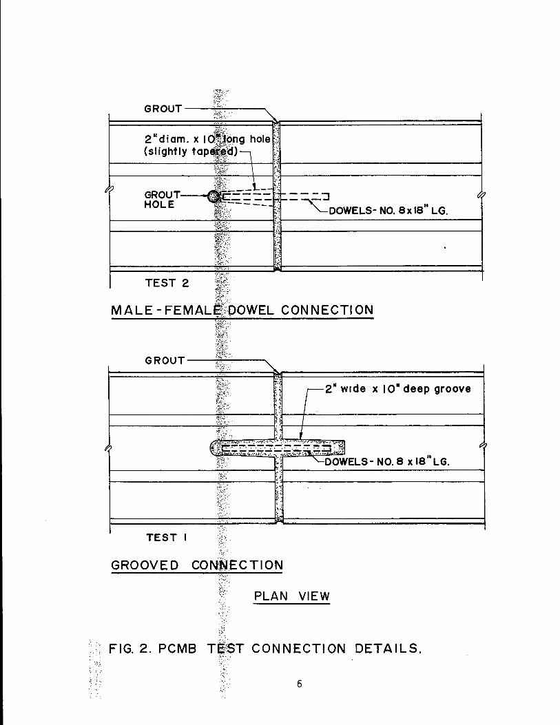
Two slightly different dowel joint details were used to connect
the 30 ft (9.1 m) precast sections together (See Figure 2). The
Male-Female dowel connection used three No.8 dowels (l in. diam. or
2.54 cm) 18 in. (.46 m) long precast in one end and three mating 2
in. diam. (5.08 cm) tapered holes cast in the opposite end as shown
in Figure 2. A pressure grout hole was cast vertically behind the
tapered female holes. The second connection used was the Grooved
Connection which also used three No.8 dowels (l in. diam or 2.54 cm)
18 in. (.46 m) long as shown in Figure 2. The Grooved Connection
was believed to be more desirable when the precast sections would
be used as a temporary barrier. It was believed that the grout and
dowels could be chipped out of the grooved block outs and the precast
sections more readily reused. This latter connection detail was
arrived at after the precast CMB sections were cast, so these grooves
were sawed instead of being precast in as would be desirable.
The lower slope dimension on the PCMB sections was increased from
3 in. to 4 in. (7.5 cm to 10 cm) so the section would maintain the
4
.. -"l •.••.••. : ••• :. '\ '"
.. '.'.' '., ...... , .. , ...... .
30'
6'-2 ~2" Coil Loop Inserts TYP. 2 Req'd. eo. section
90'
30'
Dowel Connection
2~ 2~
7'
•
Groove Conn.
•
30'
41:.::
····',··""··(ff})9/'·'.?',:j:'.:"::'.c~>"hi:~~----ri-'::~_;l;;:~·.W_-<;;il·';"Y_j;'~:-H;r t---+-!"....~;.....:.-I---+-+------...-
TEST 2 . TEST I =<0
PLAN
)
4500 lb. passenger 4500 lb. DOSS-vehicle enger vetilcle 60mph 60mph
= VIEW co , -"\1
, ::z:= N
I" ACP Base Adjacent To PCMB
-co
= v
IMPACT., SIDE .,
Longitudinal Steel Reinforcing 4 -# 4 Bars
LE::'j':;,ng Concrete Runway I'" ~e.el';:: cour~:;'> PCMB CROSS SECTION
FIGURE I. PCMB CONNECTION TEST INSTALLATION~
o
TEST 2 ~5.{~r· ~?~~~.
MALE - FEMALI~"bOWEL CONNECTION
~tW ;~~{" ..
G R 0 U T ------:;:~~yi'" ------. ........
".
TEST I .. {~:."
GROOVED CON;t~lECTION
PLAN VIEW
FIG. 2. PCMB TE/ST CONNECTION DETAILS . • • ~ :' .:;.:. <
~ : .', .: ~~., 0.
:. : .~
6
the standard 32 in. (.81 m) height after the 1 in. (2.5 cm) of asphalt
concrete fill is placed on the pavement (See Figure 1). This ACP fill
is an integral and necessary part of the barrier design for permanent
installation since it prevents lateral displacement and cracking at
the connections during vehicle impact.
Engineers and precast concrete contractors first indicated that
the PCMB units would be cast right side up and lifted at the 1/5
points from each end. An analysis (See Appendix ~) of the section
indicated that the maximum concrete stress to be expected in tension
was 57 psi T (393 kPa) for an uncracked section. This value was well
within the limits suggested by ACI-318-71. The recommended safe ul
timate concrete stress in tension is f t = I 7.5 fc• or 410 psi
(2827 kPa) for 3000 psi (20685 kPa) concrete. A cracked section
analysis was made using No.4 bars (0.5 in. diam) in each corner of
the section. The steel stress would be approximately 1100 psi T
(7585 kPa) with the concrete compressive stress less than 120 psi C
(827 kPa). All of these values are well within limits published by
AASHTO and ACIo
Insta 11 ati on
Three 30 ft (9.1 m) precast sections were installed on the concrete
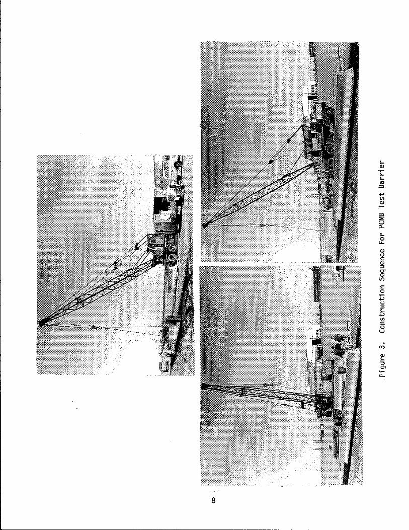
parking apron at the TAMU Research Annex as shown by Figure 1. Figure 3
shows the partial construction sequence for the test barrier. An Asphalt
Concrete leveling course was applied; each section, weighing approximately
15,000 1b (6810 kg), was set in place; the two different joints were
grouted; and the one inch (2.5 cm) ACP backup fill was placed on both
sides of the PCMB. After grouting, the joints were covered with wet
7
SQ)
or-SSIt! cc .j..l V) Q) I-
~ c....> c... S-
J: Q) u ~ Q.) ::::s 0-Q)
V')
!:: '0 or-.j..l u ::::s S
.j..l V) !:: o
c....>
M
Q) S.~
C'l or-U.
burlap to aid in curing.
A concrete grout of about a 4 in. (10 cm) slump composed of 33 lb
(15 kg) of Portland Cement, 100 lb (45 kg) sand and 15 lb (6.5 kg) water
was used to grout the groove joint. The same mix was used for the dowel
connection except that the slump was increased to 6 in. (15 cm). Two
4 in (10 cm) cylinders were cast from the mix used to grout each joint.
These were cured and tested in compression just prior to each impact test.
The five-day strength of the cylinders placed in the groove joint was
5400 psi (37200 kPa). The samples from the dowel joints tested 5740 psi
(33830 kPa) at 6 days of age.
Crash Test 1 was conducted on the Groove Connection with the 1 in.
ACP located on both sides of the PCMB to prevent lateral displacement
of the barrier under the vehicle impact. Since this test proved suc
cessful, it was decided to remove the ACP from behind the barrier for
Crash Test No. 2 on the Male-Female dowel connection. This test would
give an indication as to how the doweled connection would behave if the
precast sections were used as a temporary barrier with no ACP backup.
9
VEHICLE CRASH TESTS
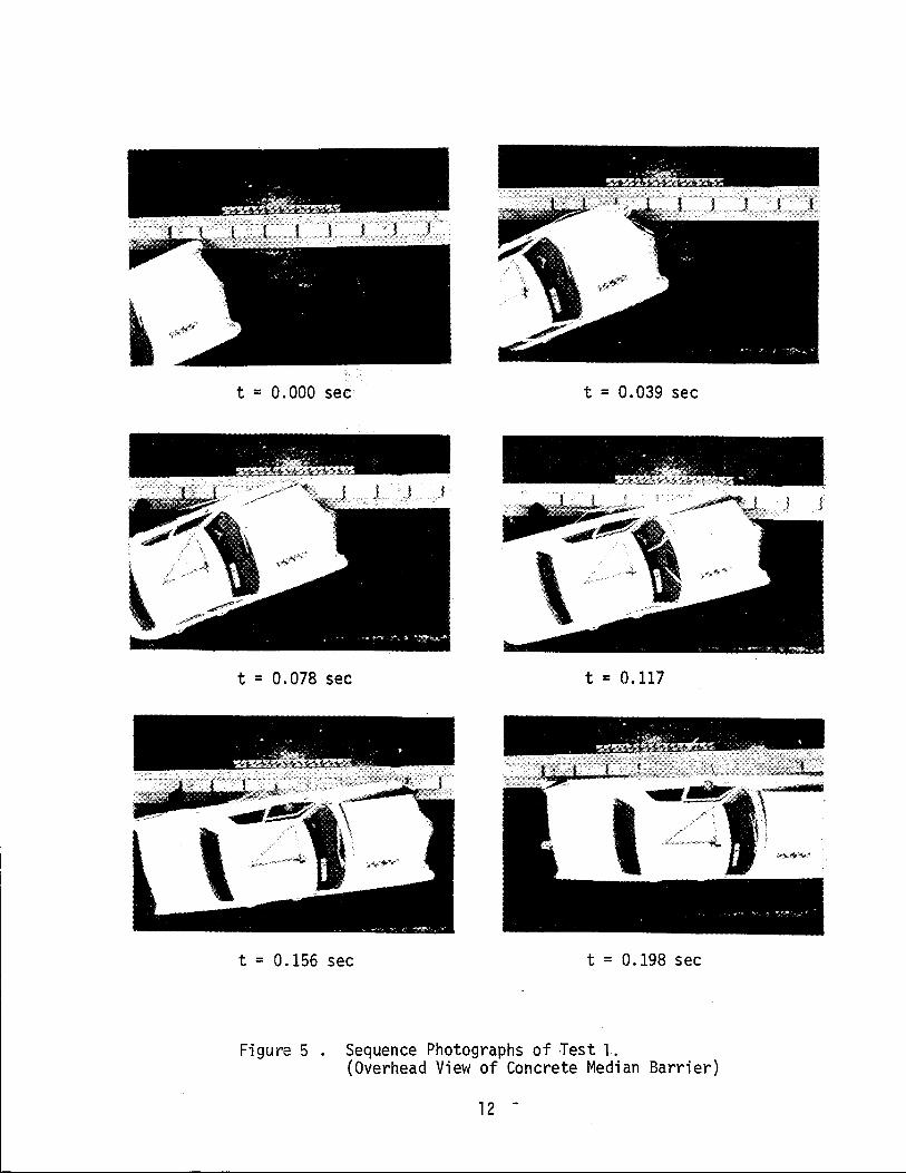
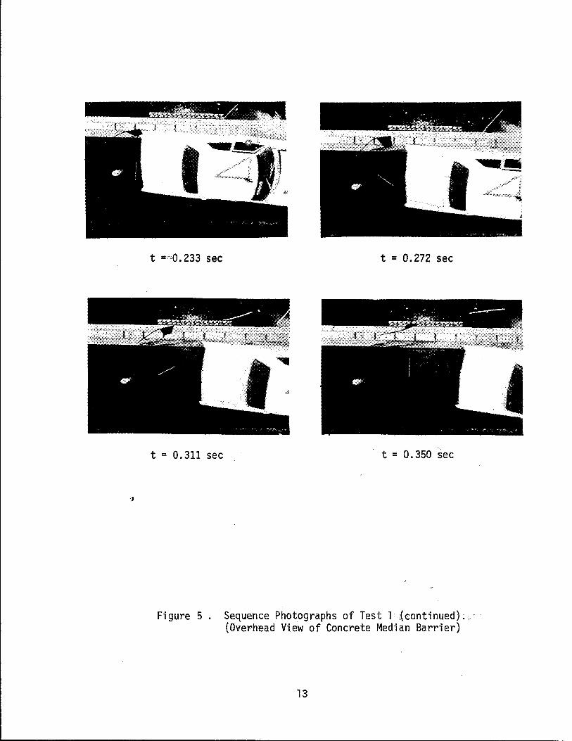
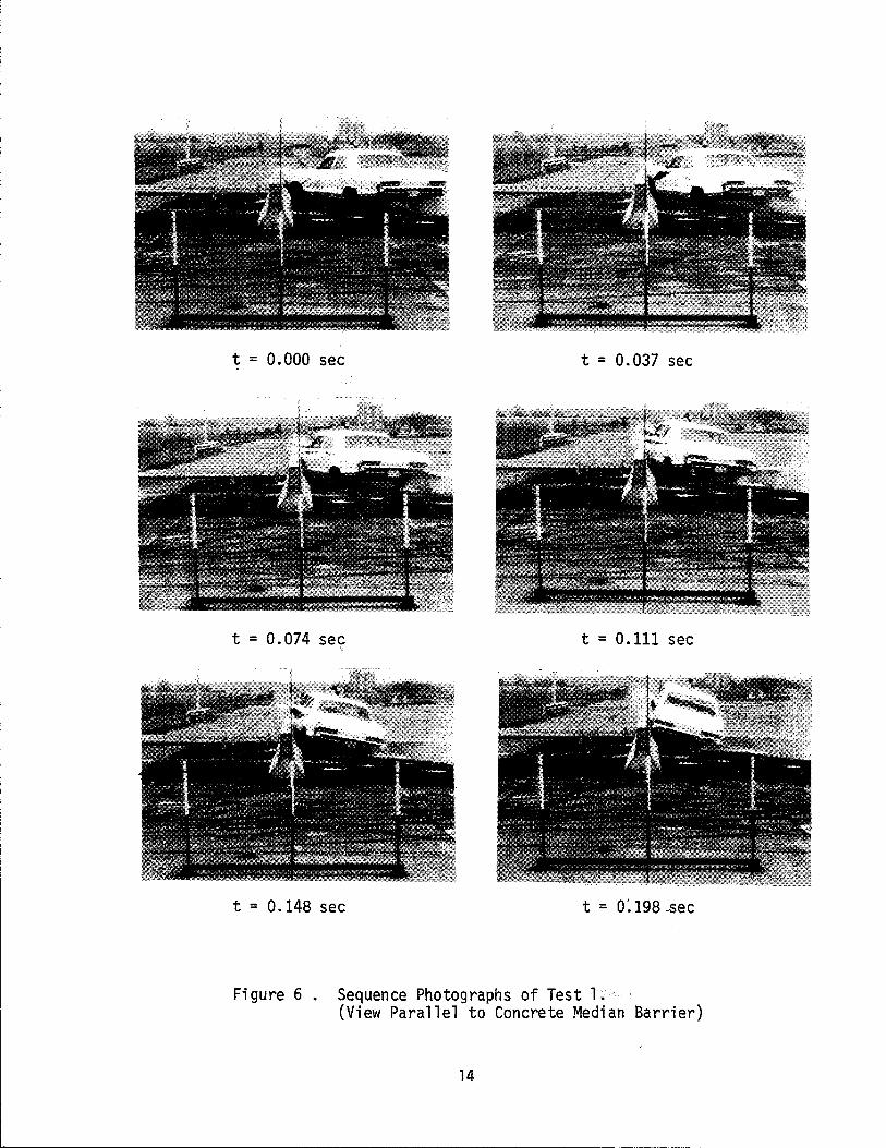
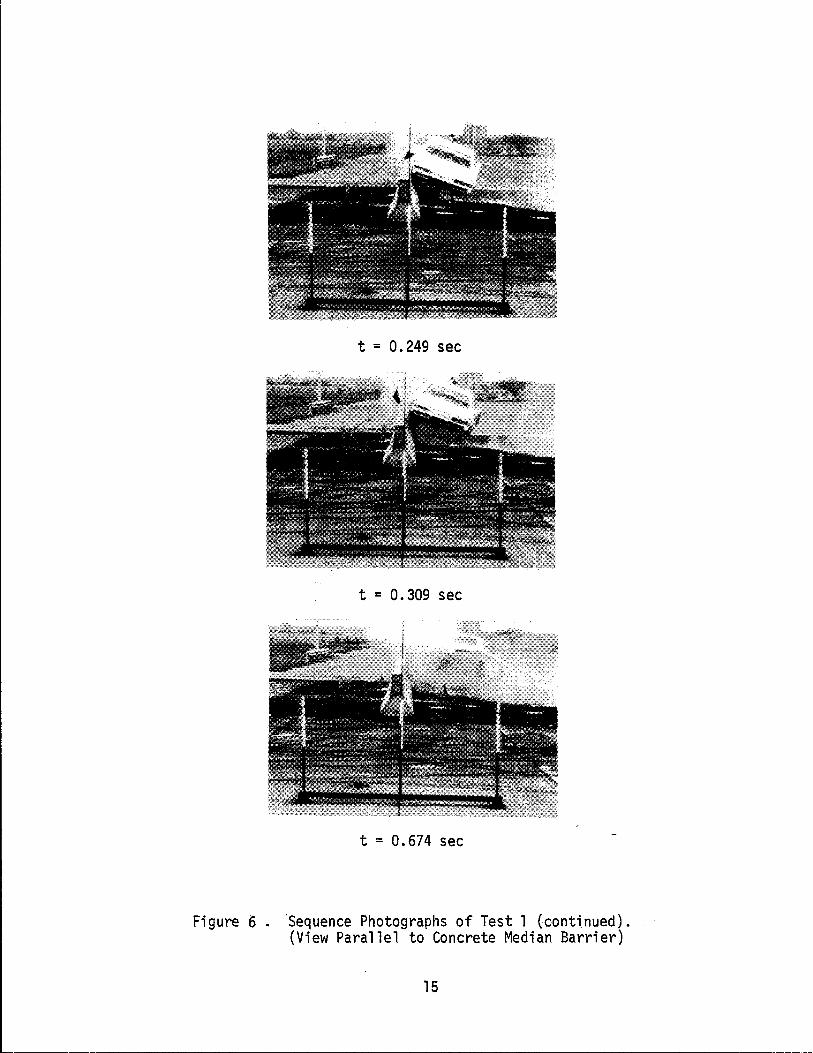
Test 1 Grooved Joint Connection
The vehicle used for Test 1 was a 1966 Pontiac 4500 lbm (2040 kg).
The impact point of the left front fender and the barrier occurred 7 ft
(2.1 m) upstream from the groove joint as shown in Figure 1. The actual
impact angle was 23.5 degrees and the actual impact velocity was 60.5 mph
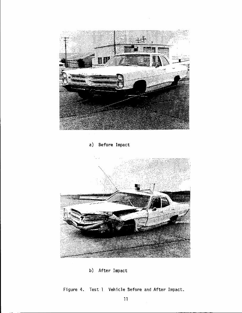
(97.3 kph). The top picture in Figure 4 shows the vehicle before impact
while the lower picture shows the vehicle after impact. The vehicle
was smoothly redirected and the exit angle was 7 degrees. The maximum
vehicle roll angle of 18 degrees occurred while the vehicle was in con
tact with the barrier. The vehicle remained upright during the test.
The front wheel and steering linkage were damaged and the vehicle was
inoperable 'after the impact. Sequence photographs showing the impact
are shown in Figures 5 and 6 from the overhead camera and parallel
camera respectively.
The average lateral deceleration taken from the high speed film
data was 7.5 gls taken over 206 milliseconds. The average longitudinal
deceleration over the same period was 1.6 gls. The barrier did not roll
or slide laterally. Figure 7 shows closeup views of the joint before
and after impact. A hairline or shrinkage crack had appeared in the
vertical face before impact. There was no evidence that this crack was
altered after impact or any other cracking at the connection during
impact. Damage to the precast barrier and joint was nil.
Test 2 Male-Female Joint
The asphaltic concrete base was removed from the back side of the
PCMB prior to Test 2 in order to determine if it was necessary to
10
a) Before Impact
b) After Impact
~ .~,J. -d
~~
Figure 4. Test 1 Vehicle Before and After Impact.
11
• y?"
. ~ '" '"
5DS~" .
t = 0.000 sec t = 0.039 sec
t = 0.078 sec t = 0.117
• _. ~ ,"' &
. - . ., "'!" ""', l
"- ~ ,,-,."~ :"' > ••
~ ,. , "
IIIi
t = 0.156 sec t = 0.198 sec
Figure 5. Sequence Photographs of Test 1. (Overhead View of Concrete Median Barrier)
12 -
.,
t ='0.233 sec t = 0.272 sec
t = 0.311 sec t = 0.350 sec
Figure 5. Sequence Photographs of Test 1 (continued) .. (Overhead View of Concrete Median Barrier)
13
t = 0.000 sec t = 0.037 sec
t = 0.074 sec t = 0.111 sec
t = 0.148 sec t = 0: 198 .sec
Fi gure 6. Sequence Photographs of Test l. (View Parallel to Concrete Median Barrier)
14
'--------------------------------------------
t = 0.249 sec
t = 0.309 sec
t = 0.674 sec
Fi gure 6. 'Sequence Photographs of Test 1 (conti nued) . (View Parallel to Concrete Median Barrier)
15
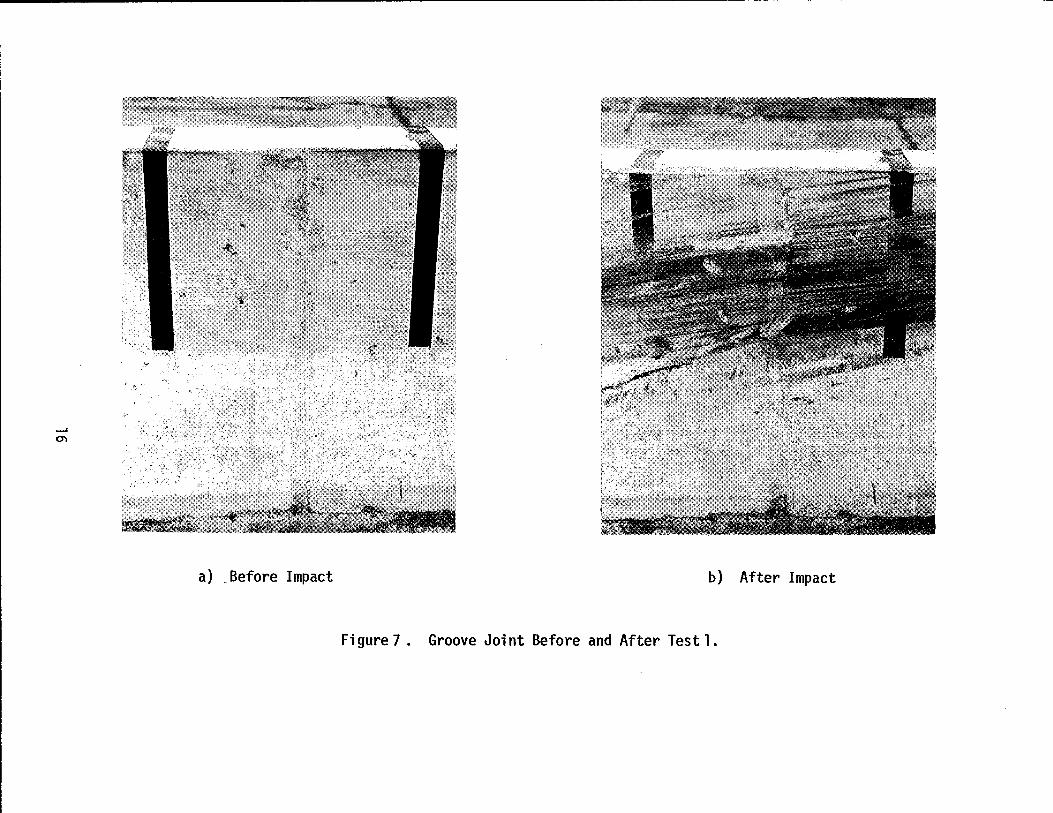
a) _Before Impact b) After Impact
Figure 7. Groove Joint Before and After Test 1.
stabilize the barrier when used as a temporary installation.
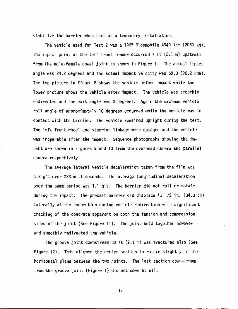
The vehicle used for Test 2 was a 1965 Oldsmobile 4540 lbm (2060 kg).
The impact point of the left front fender occurred 7 ft (2.1 m) upstream
from the male-female dowel joint as shown in Figure 1. The actual impact
angle was 24.2 degrees and the actual impact velocity was 59.8 (96.2 kmh).
The top picture in Figure 8 shows the vehicle before impact while the
lower picture shows the vehicle after impact. The vehicle was smoothly
redirected and the exit angle was 3 degrees. Again the maximum vehicle
roll angle of approximately 18 degrees occurred while the vehicle was in
contact with the barrier. The vehicle remained upright during the test.
The left front wheel and steering linkage were damaged and the vehicle
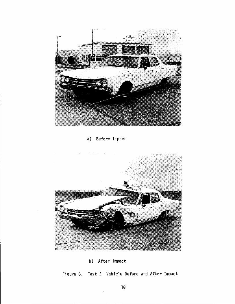
was inoperable after the impact. Sequence photographs showing the im
pact are shown in Figures 9 and 10 from the overhead camera and parallel
camera respectively.
The average lateral vehicle deceleration taken from the film was
6.3 gls over 223 milliseconds. The average longitudinal deceleration
over the same period was 1.1 gls. The barrier did not roll or rotate
during the impact. The precast barrier did displace 13 1/2 in. (34.3 cm)
laterally at the connection during vehicle redirection with significant
cracking of the concrete apparent on both the tension and compression
sides of the joint (See Figure 11). The joint held together however
and smoothly redirected the vehicle.
The groove joint downstream 30 ft (9.1 m) was fractured also (See
Figure 12). This allowed the center section to rotate slightly in the
horizontal plane between the two joints. The last section downstream
from the groove joint (Figure 1) did not move at all.
17
a) Before Impact
b) After Impact
Figure 8. Test 2 Vehicle Before and After Impact
18
t = 0.000 sec t = 0.034 sec
t = 0.057 sec t = 0.135 sec
t = 0.169 sec t = 0.203 sec
Fi gure 9. Sequence Photographs of Test 2. (Overhead View of Concrete Median Barrier)
19
~----------------------------------------------
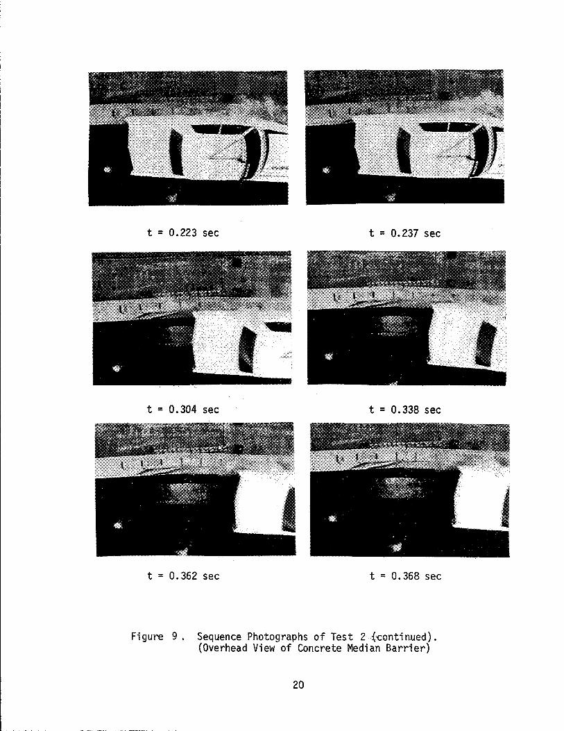
t = 0.223 sec t = 0.237 sec
t = 0.304 sec t = 0.338 sec
t = 0.362 sec t = 0.368 sec
Figure 9. Sequence Photographs of Test 2 {continued}. (Overhead View of Concrete Median Barrier)
20
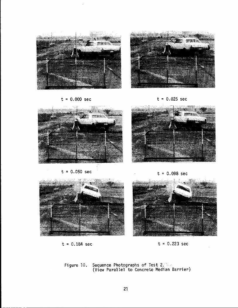
t = 0.000 sec t = 0.025 sec
t = 0.050 sec t = 0.098 sec
t = 0.184 sec t = 0.223 sec
Figure 10. Sequence Photographs of Test 2. .. (View Parallel to Concrete Median Barrier)
21
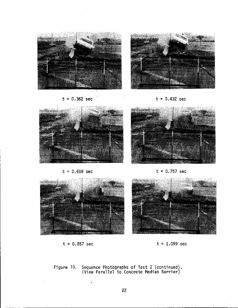
t =0.362 sec t= 0.432 sec
t = 0.659 sec t = 0.757 sec
t = 0.857 sec t = 1.099 sec
Figure 10. Sequence Photographs of Test 2 (continued). (View Parallel to Concrete Median Barrier)
22
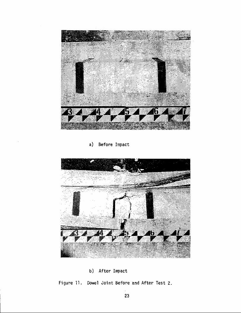
a) Before Impact
b) After Impact
Figure 11. Dowel Joint Before and After Test 2.
23
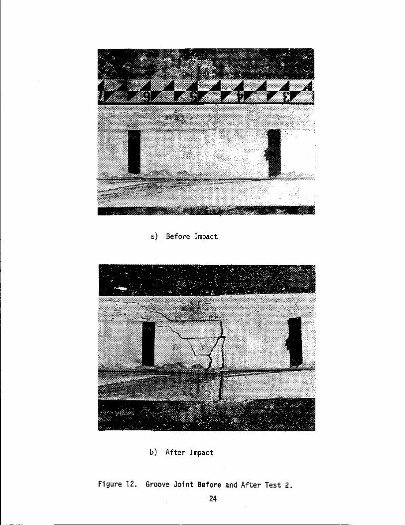
a) Before Impact
b) After Impact
Figure 12. Groove Joint Before and After Test 2.
24
DISCUSSION OF TESTS
A brief summary of the test data is shown in Table 1. In both tests
the vehicle was smoothly redirected and remained upright. The barrier did
not rotate in either tests.
When the PCMB was supported laterally by the 1 in. (2.54 cm) thick
asphaltic paving material (Test 1), it did not displace laterally and no
damage was inflicted on the precast concrete segments or connection.
For a permanent installation the 1 in. (2.54 cm) thick asphaltic paving
material or some other lateral support should be used so that maintenance
or repair cost would be small or nil.
If the PCMB is to be used as a temporary barrier, Test 2 indicates
that lateral support by the 1 in. (2.54 cm) asphaltic concrete is hot
absolutely necessary. However, the barrier can be expected to displace
laterally under vehicle impact approximately 1 ft (.3 m) and significant
cracking of the concrete will occur at the segment joints. Under low
speed and/or low angle impacts the lateral displacement and cracking
of the concrete would probably be minimal.
One can conclude from these two tests that the precast concrete
median barrier (PCMB) will function as designed when the 30 ft (9.1 m)
sections are connected by either of the two connection used and backed
up with 1 in. (2.54 cm) of ACP. This type of installation is recommended
for permanent installations. If the PCMB is used as a temporary in
stallation either connection should be acceptable, however considerable
maintenance can be anticipated if the ACP or some other backup is not
used to prevent sliding.
25
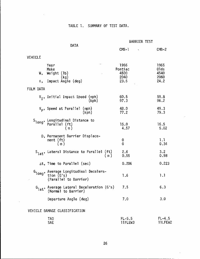
TABLE 1. SUMMARY OF TEST DATA.
BARRIER TEST DATA
CMB-l CMB-2
VEHICLE
Year 1966 1965 Make Pontiac Olds
W, Weight (lb) 4500 4540 (kg) 2040 2060
6, Impact Angle (deg) 23.5 24.2
FILM DATA
VI' Initial Impact Speed (mph) 60.5 59.8 (kph) 97.3 96.2
Vp' Speed at Parallel (mph) 48.0 49.3 (kph) 77 .2 79.3
S Longitudinal Distance to long' Parallel (ft) 15.0 16.5 ( m) 4.57 5.02
0, Permanent Barrier Displace-ment (ft) 0 1.1
( m ) 0 0.34
Slat' Lateral Distance to Parallel (ft) 2.6 3.2 ( m ) 0.55 0.98
bt, Time to Parallel (sec) 0.206 0.223
Glon ' Average Longitudinal Decelera-g tion (GiS) 1.6 1.1
(Parallel to Barrier)
Gl t' Average Lateral Deceleration a (Normal to Barrier)
(GiS) 7.5 6.3
Departure Angle (deg) 7.0 3.0
VEHICLE DAMAGE CLASSIFICATION
TAD FL-S.S FL-4.S SAE 11 FLEW3 11 LFEW2
26
CONCLUSIONS
Past experience has shown that the Concrete Median Barrier (CMB) is an
economical and effective traffic barrier. Investigation into the use of a
precast concrete median barrier stemmed from the interest involved in
utilizing a barrier to be prefabricated concurrently with roadway construc
tion. This more effective utilization of work force as well as early pro-
ject completion and acceptance could provide measurable potential savings to
both contractor and the State. When installing this barrier on existing
facilities, it is frequently desirable to precast the concrete median barrier
(PCMB) so the units can be quickly installed during low traffic volume periods.
The 30 ft ( 9.1 m ) long sections with grouted dowel connections and the
1 in. asphalt concrete paving (ACP) fill material behind the barrier
proved to be an effective barrier in redirecting 4500 lbm (2040 kg) vehicles
impacting at 60 mph (96.5 km/hr) and 25 degrees.
If the 1 in. ACP or some other backup device is not used to prevent
lateral sliding the doweled connections tested here appear to be adequate,
however considerable maintenance can be anticipated after high speed, high
angle impacts. This type installation (without backup device) should only be
used as a temporary barrier.
Four #4 longitudinal reinforcing bars are adequate for handling and
lifting requirements provided that the sections are cast right side up.
Where the units will be cast bottom side up (for simpler form design and
removal) four #5 longitudinal bars are recommended provided two pickup
points located approximately 6 ft 2~ in. (1.9 m) from each end are used.
The recommendations for reinforcing steel are intended to produce
added safety during installation and reduced maintenance when in service.
These concrete sections could have been designed as plain unreinforced
concrete members. 27
REFERENCES
1. Michie, J. D., and Bronstad, M. E., IILocation, Selection, and Maintenance of Highway Traffic Barriers,1I NCHRP Report 118,1971.
2. Bronstad, M. E. Personal Conversation on July 18, 1975.
3. Lundstrom, L. C., Skeels, P. C., Englund, B. R., and Rogers, R. A., IIA Bridge Parapet Designed for Safety,1I Highway Research Record No. 83, HRB, 1965, pp. 169-183.
4. Young, R. D., Post, E. R., and Ross, Jr., H. E., IISimulation of Vehicle Impact with Texas Concrete Median Barrier: Test Comparisons and Parameter Study, II Hi ghway Research Record No. 460, HRB, 1973, pp. 61-72.
5. Post, E. R., Hirsch, T. J., Hayes, G. G., and Nixon, J. F., IIVehicle Crash Test and Evaluation of Median Barriers for Texas Highways,1I Highway Research Record No. 460, HRB, 1973, pp. 97-113.
6. Ross, Hayes E. Jr., IIImpact Performance and a Selection Criteria for Texas Median Barriers,1I TTl Research Report 140-8, Texas A&M University, April 1974.
7. Bronstad, M. E., and Michie, J. D., IIRecommended Procedures for Vehicle Crash Testing of Highway Structures,1I NCHRP Report 153, 1974.
28

APPENDIX A
HANDLING STRESSES
29
APPENDIX A
HANDLING STRESSES
Handling stresses are extremely important in the design of precast
concrete units. The design of precast concrete members should consider
service loads as well as temporary ltfting, storage, hauling and instal
lation loads. Brittle failure of an unreinforced precast concrete unit
during handling operations would be dangerous to construction personnel.
Plain concrete stresses for dead load only with lifting pOints 6.2 ft
(1.9 m) from each end would be 56.8 psi T (392 kPa). According to AASHTO-
PCI design criteria for precast concrete piling and beams and impact
factor of 1.5 is reasonable for such designs. Applying this as an im
pact factor gives a maximum anticipated stress of 85 psi T (588 kPa).
According ACI 318-71 a safe ultimate stress for concrete in tension
is 7.5 ~ which for 3000 psi (20685 kPa) concrete at 28 days would be
fallow 28 = 7.5 13000 = 410 psi T (2826 kPa) or at 7 days
fallow 7 = 7.5 12250 = 355 psi T (2448 kPa)
The factor of safety against cracking or brittle failure for plain
concrete for handling units right side up would be 3~~ = 4.2. The
addition of the four reinforcing bars is added safety. An acceptable
method to designers and possibly a less expensive method of manufacturing
is to cast the 30 ft sections of median barrier upside down. These sections
are next removed from the forms by lifting with coil loop inserts or cables
cast into the bottom of barrier approximately 6 ft - 2~ in. (1.9 m) from
each end. The barrier section will then be set back on the surface
bottom side up and allowed to cure. The curing procedure should conform
to job specifications. Next the barrier section is laid on its side and
30
attachments are made to inserts cast in the narrow top of the barrier or
to choker cables wrapped around the barrier at pickup points. The barrier
section is then righted by lifting (sideways) on the inserts and the unit
then moved to a storage location or truck bed and 'hauled to the job site.
Lifting from the bottom and righting induces completely different
handling stresses than occur when the barrier is cast right side up. The
critical stresses occur when the barrier is on its side. Assuming lifting
points at 6.2 ft (1.9 m) from each end of the section, the maximum bending
stress for plain concrete would be 104.3 psi T (719 kPa). Using an impact
factor of 1.5- and 7-day old concrete the factor of safety would be
104.~5~ 1.5 = 2.3. Any symmetrical placement of reinforcing would increase
this factor of safety without causing any over stress in the steel.
Should a cracked section be encountered during handling then the con
crete stress would be increased to 461 psi C (3180 kPa) which is well
within the 7-day limits of 2250 psi C (15,500 kPa) of 3,000 psi C (20,700
kPa) concrete. Steel stresses for four #5 bars are 13,940 psi T (96,120
kPa). The factor of safety for failure due to yield for Grade 40 steel
is: _ 40,000_ F.S. - 13,940 x 1.5 - 1.9
and for Grade 60 steel _ 60,000_
F.S. - 13,940 x 1.5 - 2.9
It is believed that these precast concrete members should contain some
steel for safety during construction and to reduce maintenance during
inservice operations.
31

APPENDIX B
FILM DATA
32
APPENDIX B
INSTRUMENTATION
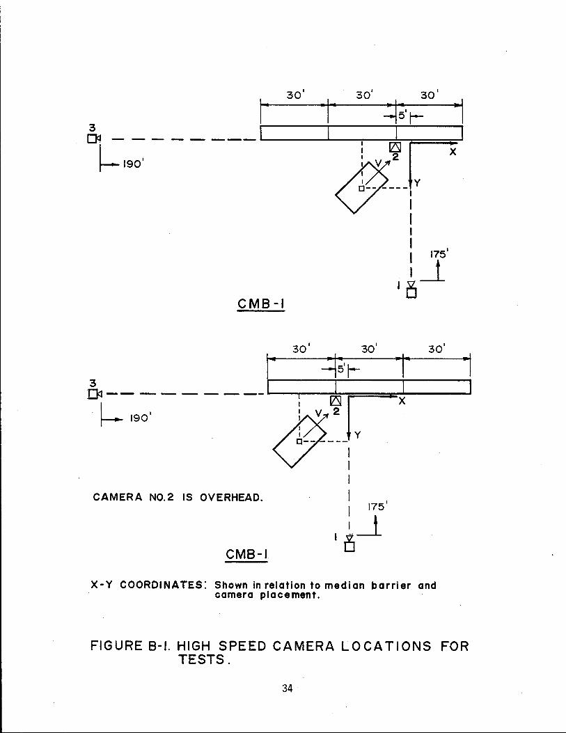
The instrumentation used for both tests consisted primarily of three
high speed cameras located as shown in Figure B-1. One camera was located
perpendicular to and 175 ft (53.3 m) from the face of the barrier. The
perpendicular line of site was 5 ft (-1.5 m) downstream from the joint
being impacted. An overhead camera was located directly above the joint
being impacted. The third camera was in line with and parallel to the
barrier located 190 ft (58.1 m) from the upstream end of the barrier.
In addition, a documentary camera was located in the vicinity of camera
no. 1. A flash bulb, operated by a tape switch and located on top of the
vehicles, was used to synchronize the films from the high speed cameras.
Each of the cameras were further controlled by timing lights.
Stadia markers were placed on top of each vehicle as shown in Figure B-
2. Each marker was coded so that position, roll pitch and yaw could be
determined from the two ground mounted cameras.
The determination of the strength and stability of the barrier is a
primary objective of this study. The overhead camera, no. 2, and the par
allel camera, no. 3, were used to measure lateral displacement and barrier
roll. A stadia board was placed behind the barrier at the joint impacted
to aid in the measuring of lateral displacement.
33
3 oq - - - - - - -- '-------L-..-Ir--rll3J~===;:::J
~ l 2 X
190' 8'---;Y
I I I
175'
i~ ' 0
CMB-I
30' 30' 30'
CMB-I
I 175' I
I~~ CAMERA NO.2 IS OVERHEAD.
x-v COORDINATES: Shown in relation to median barrier and camera placement.
FIGURE B-1. HIGH SPEED CAMERA LOCATIONS FOR TESTS.
34
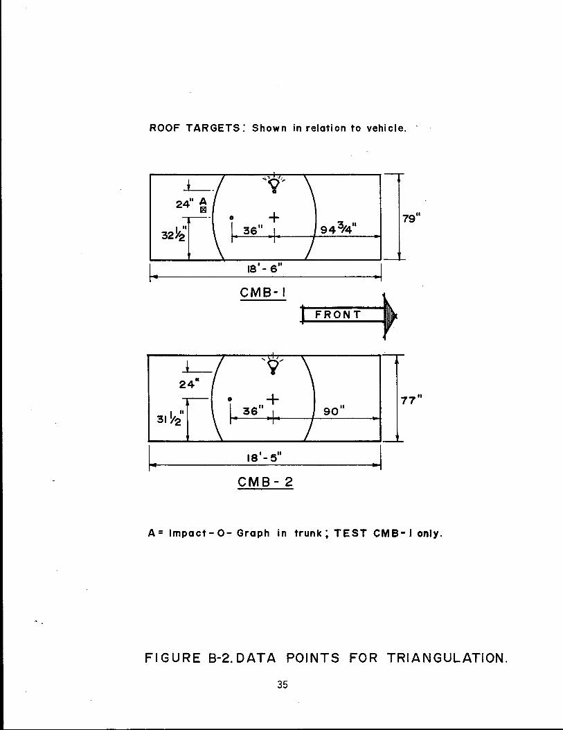
ROOF TARGETS: Shown in relation to vehicle. . .
L-_ ~(jl,
• 24" A s
79" 943/4" 32Y~'
~ 18' - 6" .1 CMB-I
~ I FRONT
* '9'
24"
77"
31~~' 90"
I~ 18'- 5" .1 CMB-2
A = Impact - 0- Graph in trunk; TEST CMB- J only.
FIGURE 8-2.DATA POINTS FOR TRIANGULATION.
35
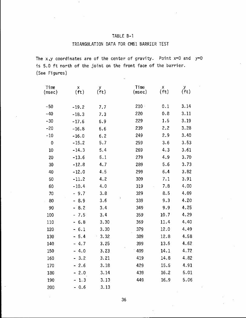
TABLE B-1
TRIANGULATION DATA FOR eMB1 BARRIER TEST
The x,y coordinates are of the center of gravity. Point x=O and y=O
is 5.0 ft north of the joint on the front face of the barrier.
(See Figures)
Time x y Time x y (msec) (ft) (ft) (msec) (ft) (ft)
-50 -19.2 7.7 210 0.1 3.14
-40 -18.3 7.3 220 0.8 3.11
-30 -17.6 6.9 229 1.5 3.19
-20 -16.8 6.6 239 2.2 3.28
-10 -16.0 6.2 249 2.9 3.40
0 -15.2 5.7 259 3.6 3.53
10 -14.3 5.4 269 4.3 3.61
20 -13.6 5.1 279 4.9 3.70
30 -12.8 4.7 289 5.6 3.73
40 -12.0 4.5 299 6.4 3.82
50 -11.2 4.2 309 7.1 3.91
60 -10.4 4.0 319 7.8 4.00
70 - 9.7 3.8 329 8.5 4.09
80 - 8.9 3.6 339 9.3 4.20
90 - 8.2 3.4 349 9.9 4.25
100 - 7.5 3.4 359 10.7 4.29
110 - 6.8 3.30 369 11.4 4.40
120 - 6.1 3.30 379 12.0 4.49
130 - 5.4 3.32 389 12.8 4.58
140 - 4.7 3.25 399 13.5 4.62
150 - 4.0 3.23 409 14.1 4.72
160 - 3.2 3.21 419 14.8 4.82
170 - 2.6 3.18 429 15.5 4.91
180 - 2.0 3.14 439 16.2 5.01
190 - 1. 3 3.13 449 16 .. 9 5.06
200 - 0.6 3.13
36
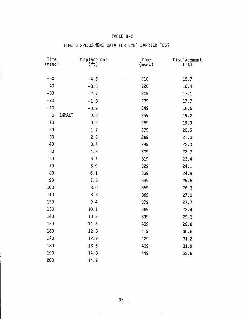
TABLE B-2
TIME DISPLACEMENT DATA FOR CMBl BARRIER TEST
Time Displacement Time Displacement (msec) ( ft) (msec) (ft)
-50 -4.5 210 15.7 -40 -3.6 220 16.4 -30 -2.7 229 17.1 -20 -1.8 239 17.7 -10 -0.9 249 18.5
0 IMPACT 0.0 259 19.2 10 0.9 269 19.9 20 1.7 279 20.5 30 2.6 289 21. 3 40 3.4 299 22.0 50 4.2 309 22.7 60 5.1 319 23.4 70 5.9 329 24.1 80 6.1 339 24.9 90 7.3 349 25.6
100 8.0 359 26.3 110 8.8 369 27.0 120 9.4 379 27.7 130 10.1 389 28.4 140 10.9 399 29.1 150 11.6 409 29.8 160 12.3 419 30.5 170 12.9 429 31.2 180 13.6 439 31.9 190 14.3 449 32.6 200 14.9
37
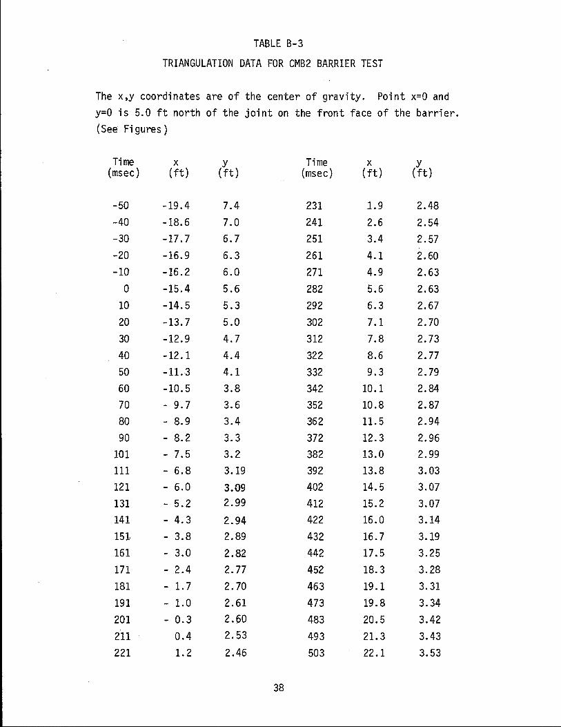
TABLE B-3
TRIANGULATION DATA FOR CMB2 BARRIER TEST
The x,y coordinates are of the center of gravity. Poi nt x=O and y=O is 5.0 ft north of the joint on the front face of the barrier. (See Fi gures )
Time x y Time x y (msec) (ft) (ft) (msec) (ft) (ft)
-50 -19.4 7.4 231 1.9 2.48 -40 -18.6 7.0 241 2.6 2.54 -30 -17.7 6.7 251 3.4 2.57 -20 -16.9 6.3 261 4.1 2.60 -10 -16.2 6.0 271 4.9 2.63
0 -15.4 5.6 282 5.6 2.63 10 -14.5 5.3 292 6.3 2.67 20 -13.7 5.0 302 7.1 2.70 30 -12.9 4.7 312 7.8 2.73 40 -12.1 4.4 322 8.6 2.77 50 -11.3 4.1 332 9.3 2.79 60 -10.5 3.8 342 10.1 2.84 70 - 9.7 3.6 352 10.8 2.87 80 - 8.9 3.4 362 11. 5 2.94 90 - 8.2 3.3 372 12.3 2.96
101 - 7.5 3.2 382 13.0 2.99 111 - 6.8 3.19 392 13.8 3.03 121 - 6.0 3.09 402 14.5 3.07 131 - 5.2 2.99 412 15.2 3.07 141 - 4.3 2.94 422 16.0 3.14 151- - 3.8 2.89 432 16.7 3.19 161 - 3.0 2.82 442 17.5 3.25 171 - 2.4 2.77 452 18.3 3.28 181 - 1. 7 2.70 463 19.1 3.31
191 - 1.0 2.61 473 19.8 3.34 201 - 0.3 2.60 483 20.5 3.42 211 0.4 2.53 493 21.3 3.43 221 1.2 2.46 503 22.1 3.53
38
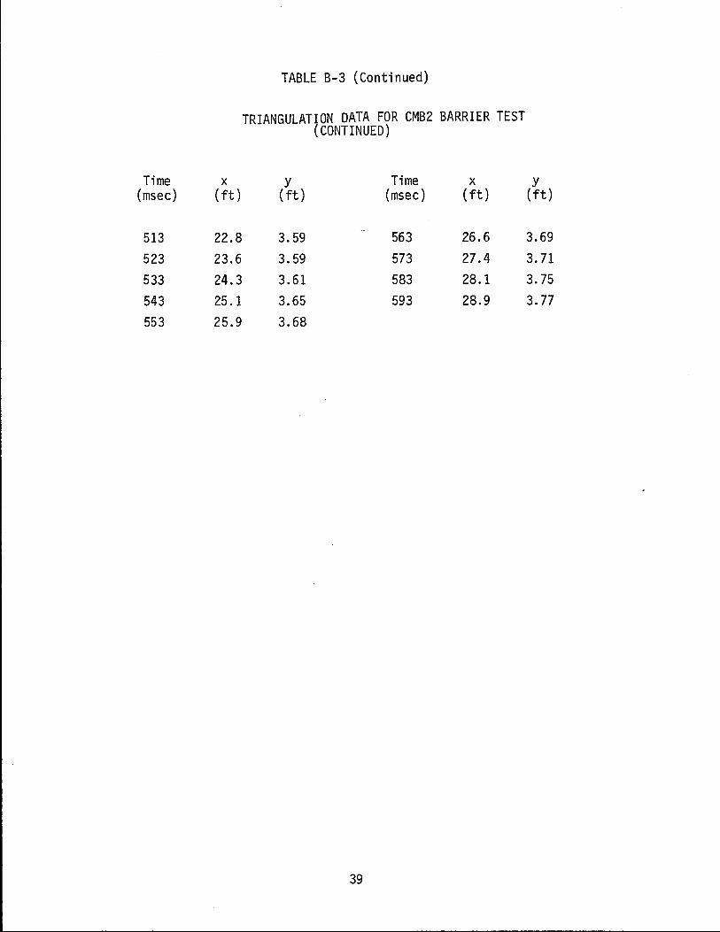
Time x (msec) ( ft)
513 22.8 523 23.6 533 24.3 543 25.1 553 25.9
TABLE B-3 (Continued)
TRIANGULATION DATA FOR CMB2 BARRIER TEST (CONTINUED)
y Time x (ft) (msec) (ft)
3.59 563 26.6 3.59 573 27.4 3.61 583 28.1 3.65 593 28.9 3.68
39
y (ft)
3.69 3.71 3.75 3.77
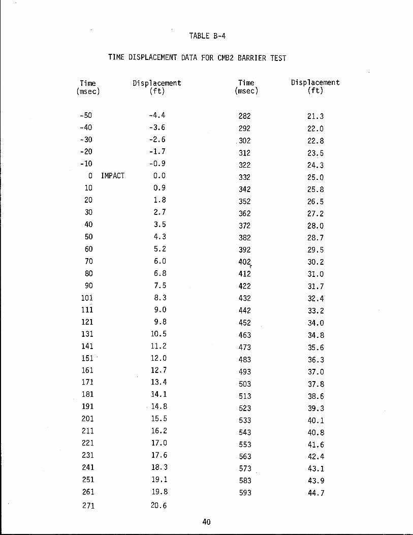
TABLE B-4
TIME DISPLACEMENT DATA FOR CMB2 BARRIER TEST
Time Displacement Time Displacement (msec) (ft) (msec) (ft)
-50 -4.4 282 21. 3 -40 -3.6 292 22.0 -30 -2.6 .302 22.8 -20 -1.7 312 23.5 -10 -0.9 322 24.3
0 IMPACT 0.0 332 25.0 10 0.9 342 25.8 20 1.8 352 26.5 30 2.7 362 27.2 40 3.5 372 28.0 50 4.3 382 28.7 60 5.2 392 29.5 70 6.0 402 30.2
r
80 6.8 412 31.0 90 7.5 422 31. 7
101 8.3 432 32.4 .. 111 9.0 442 33.2 121 9.8 452 34.0 131 10.5 463 34.8 141 11.2 473 35.6 151 12.0 483 36.3 161 12.7 493 37.0 171 13.4 503 37.8 181 14.1 513 38.6 191 . 14.8 523 39.3 201 15.5 533 40.1 211 16.2 543 40.8 221 17.0 553 41.6 231 17.6 563 42.4 241 18.3 573 43.1 251 19.1 583 43.9 261 19.8 593 44.7
271 20.6
40


![SECTION 034500 - PRECAST ARCHITECTURAL CONCRETE · Architectural precast concrete cladding [and load-bearing] units. ... PRECAST ARCHITECTURAL CONCRETE 034500 ... Architectural Cladding](https://img.pdfslide.us/doc/110x75/5ae006067f8b9a1c248cb77e/section-034500-precast-architectural-concrete-precast-concrete-cladding-and-load-bearing.jpg)