Embed Size (px)
Citation preview
11th World Congress on Structural and Multidisciplinary Optimisation 7 -12, June 2015, Sydney Australia
1
Crash Optimization of Automobile Frontal and Side Structures Using Equivalent Static Loads
Youngmyung Lee 1, Jin-Seok Ahn2, and Gyung-Jin Park3
1 Hanyang University, Seoul, Republic of Korea, [email protected]
2 Hanyang University, Seoul, Republic of Korea, [email protected] 3 Hanyang University, Ansan, Republic of Korea, [email protected]
1. Abstract Many commercial automobile industries are seeking to design the automobile structure for improvement of passenger safety as well as reduction of the mass of the automobile. Optimization can be employed to accommodate the crash environment. The automobile crash optimization problem has large nonlinearity in analysis while the analysis is carried out in the time domain. Although the performance of the computer has been significantly improved, automobile crash optimization still needs considerable computational cost. The equivalent static loads (ESLs) method has been developed for such nonlinear dynamic response structural optimization. The ESLs are static loads that generate the same displacement in the linear static analysis as those of the nonlinear dynamic analysis at a certain time step. The ESLs are generated at all the time steps and used as multiple external forces in linear static response structural optimization. Nonlinear analysis and linear static response optimization using ESLs are carried out sequentially until the convergence criteria are satisfied. A new ESLs method is proposed for automobile crash optimization and the proposed method is verified using two practical examples. Crash optimization under a frontal impact performed to minimize the mass, and the thicknesses of the structure are determined to satisfy the relative distance constraints. The side structure of an automobile is optimized under a side impact test. The mass is minimized while the regulation of Insurance Institute for Highway Safety (IIHS) is satisfied. The regulation is the limit of the maximum intrusion that is the relative distance between the B-pillar and the center line of the seat. The resultant designs are discussed from a practical viewpoint. 2. Keywords: Structural optimization, equivalent static loads (ESLs), frontal structure, side impact test, moving deformable barrier (MDB). 3. Introduction Automobile safety regulations have become more stringent in the last decades. Many automobile industries are seeking to design the automobile structure for safety as well as reduction of the automobile mass. It is well-known that the mass of an automobile is one of the important factors for the fuel cost. Automobile structural optimization has been utilized to minimize an objective function such as mass while the conditions for safety are satisfied [1]. Automobile crash optimization generally uses nonlinear dynamic analysis that has large nonlinearity in the time domain. Therefore, optimization techniques for crash optimization should be able to address the nonlinearity in the time domain with an appropriate manner. Automobile industries are trying to utilize a high-fidelity model in structural optimization. An intuitive design based on the designer's experience has been popularly utilized. The conventional optimization paradigm is difficult to use for crash optimization due to extremely high cost. Meta-models are actively used for optimization with approximated functions to save the cost [2-4]. The meta-model approaches vary depending on the sampling method, fitting function or interpolation function, and the optimum solution depends on the selection of a method. When the number of design variables is large, the number of sampling, i.e., the number of nonlinear dynamic analyses can be quite large. The equivalent static loads method (ESLM) has been utilized to save the computational cost as well as to use a gradient-based optimization process. Since the ESLM was introduced by Choi and Park in 1999 [5], it has been applied to various practical examples [6-9]. Two domains such as the analysis domain and the design domain are defined. In the analysis domain, nonlinear dynamic analysis is performed, equivalent static loads (ESLs) are generated by using the displacement output of the analysis domain, and linear static structural optimization is carried out using the ESLs in the design domain. Generally, the finite element (FE) models of the two domains are the same. An FE model for crash analysis may not have boundary conditions; however, an FE model for linear static structural optimization requires boundary conditions. A novel method is proposed to solve this discrepancy by using the inertia relief technique [10] when using the ESLM. The proposed method is validated by solving two practical examples. The two examples are optimizations of a frontal structure and a side structure. Optimization of the frontal structure is carried out under the low speed impact test protocol of the Electronic Code of Federal Regulations (e-CFR) [11]
2
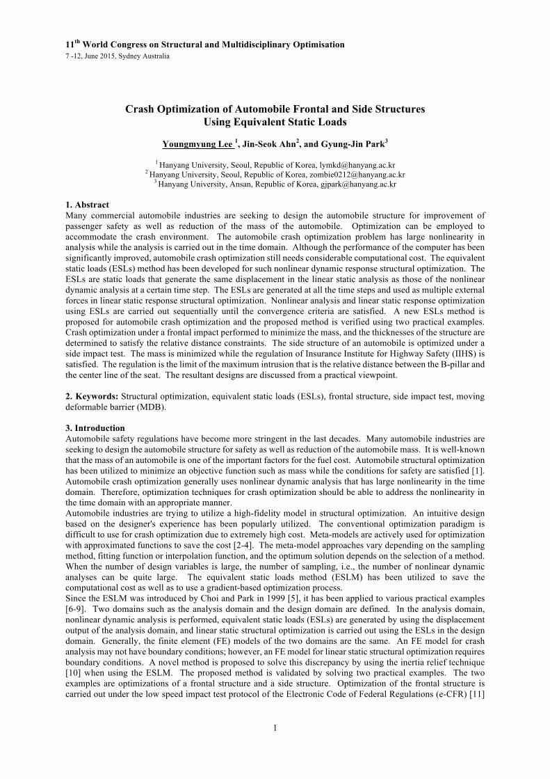
and side impact optimization is carried out based on the IIHS [12]. Nonlinear dynamic analysis is carried out using LS-DYNA 971 [13], linear static response structural optimization is conducted by using NASTRAN SOL 200, and calculation of ESLs is utilized using NASTRAN DMAP [14]. A computer program is developed for optimization with ESLM [15]. 4. Test protocol of crash analysis 4.1. Frontal structure An important function of an automobile frontal structure is to absorb impact energy. It reduces the physical injuries to passengers as well as damages to the interior of the engine room. There are two kinds of the low speed impact test of the e-CFR. One is the pendulum impact test and the other is the barrier impact test. In the pendulum impact test, a frontal structure is fixed at the rear end and the pendulum impacts the frontal structure. In the case of the barrier impact test, the frontal structure impacts a fixed rigid wall at a low velocity of 8 km/h. Jeong et al. performed crash optimization using the pendulum impact test [8]. In this research, the barrier impact test is utilized. Thus, the finite element model does not have any boundary conditions in nonlinear dynamic analysis. The finite element model is divided into 29 parts that has the 8,526 finite elements, and the total mass is 16.16 kg. The specific sizes of the frontal structure are illustrated in Figure 1 a). 4.1. Side structure According to the side impact test protocol of the IIHS, the side impact test uses a motionless test automobile impacted by an IIHS moving deformable barrier (MDB). The mass of MDB is 1,500 kg, and the MBD impacts at a velocity of 50 km/h. In this research, the structural rating of IIHS is utilized. For example, it is evaluated as ‘good’, if the distance from the B-pillar point with maximum intrusion to a seat centerline is greater than 125mm. The finite element model is from the National Crash Analysis Center [16], which is the Yaris model from Toyota. The total number of finite elements is 974,445 and the total mass is 1,247 kg. The FE model of IIHS MDB is provided by the Livermore Software Technology Corporation [13]. Figure 1 b) shows the FE model with MBD. In the initial side impact simulation, the maximum distance between the deformed B-pillar and the seat centerline is 122.49 mm. In other words, the initial design would receive a nearly ‘good’ structural rating. 5. Equivalent static loads method for nonlinear dynamic response structural optimization The schematic view of the two domains is presented in Figure 2. In the analysis domain, nonlinear dynamic response analysis is carried out. Then ESLs are generated. In the design domain, generated ESLs are applied as external loads in linear static response structural optimization. The process of ESLM is repeated until the convergence criterion is satisfied. The repeated process is called a design cycle. The process of calculating ESLs is described in detail. Eq.(1) is the governing equation of nonlinear dynamic response analysis.
N N N( , ( )) ( ) ( , ( )) ( ) ( ) ( 0, , )t t t t t t l+ = =M b z z K b z z f (1) where nR∈b is the design variable vector, n is the number of design variables, M is the mass matrix, N ( )tz is
Figure 2: Schematic view of the equivalent static loads method
Figure 1: Finite element model: a) a frontal structure, and b) a side impact test
412mm
762mm
1,127mm
Rigid wall a) b)
3
the acceleration vector, K is the stiffness matrix, N ( )tz is the displacement vector, and ( )tf the is dynamic load vector, subscript N means that it is from nonlinear analysis, t is time and l is the number of time steps. The following equation is the governing equation of linear static analysis: L ( ) =K b z f (2) where the subscript L means that it is from linear analysis, z is the displacement vector and f is the force vector. The displacement vector z is replaced by N ( )tz to calculate ESLs in the following equation: eq L N( ) ( ) ( ); 1,...,s t s l= =f K b z (3) Thus, the ESLs vector eq ( )sf is calculated as the product of linear stiffness matrix L ( )K b and the displacement vector N ( )tz . Since the number of sets of ESLs is the same as that of time steps, the notations s and t exactly correspond. Finally, ESLs are applied as multiple loading conditions for linear static response structural optimization. The overall process is as follows:
Step 1. Set the initial design variables (cycle number: 0k = , design variables: ( ) (0)k =b b ). Step 2. Perform nonlinear dynamic response analysis with ( )kb . Step 3. Calculate the ESLs using Eq.(3). Step 4. Solve the linear static response structural optimization problem with ESLs using inertia relief
analysis. Since the structures have no boundary conditions, the inertia relief technique is utilized [10].
Step 5. When 0k = , go to Step 6. When 0k > , if the convergence criterion is satisfied then terminate the process. Otherwise, go to Step 6.
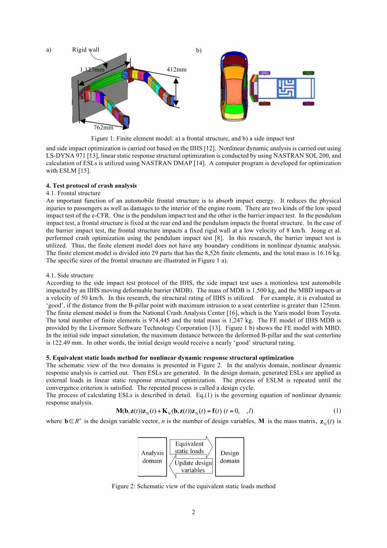
Step 6. Update the design variables, set 1k k= + and go to Step 2. 6. Automobile crash optimization using equivalent static loads 6.1. Frontal structure Figure 3 shows the 28 design variables among 29 parts and three grids that are utilized for the displacement constraints. The objective function is the entire mass of the structure, and size optimization is carried out. The displacement constraints are defined using the distance from A to C and B to C . Using the displacement constraints, the bumper intrusion is constrained. The bound for the constraint is 140.5 mm that is the result of the initial nonlinear dynamic analysis.
Figure 3: Design variables of a frontal structure and grids of displacement constraints Grid A
Grid B
Grid C
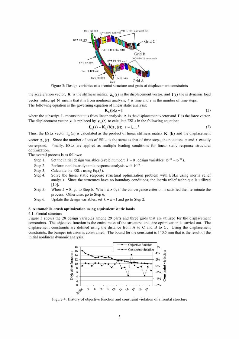
Figure 4: History of objective function and constraint violation of a frontal structure
4
Design formulation is as follows: Find ( 1,2,...,28)ib i = (4) to minimize mass (5) subject to x,A x,C 140.5mmδ δ− ≥ (6)
x,B x,C 140.5mmδ δ− ≥ (7)
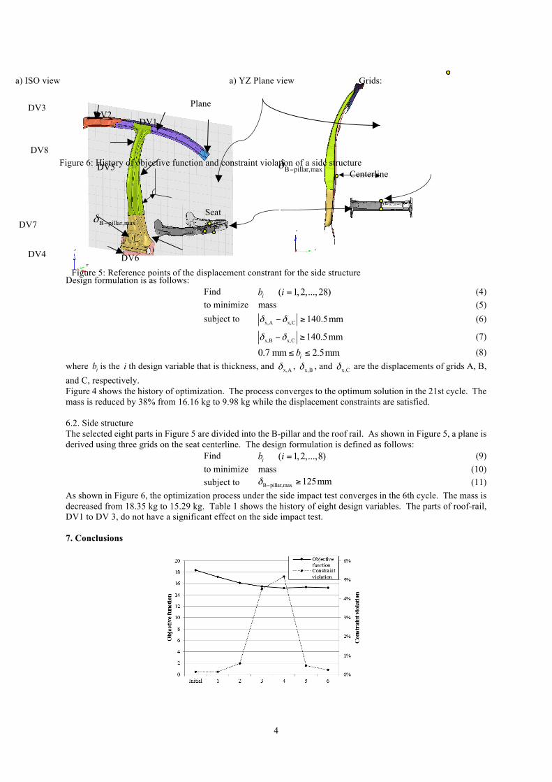
0.7 mm 2.5mmib≤ ≤ (8) where ib is the i th design variable that is thickness, and x,Aδ , x,Bδ , and x,Cδ are the displacements of grids A, B, and C, respectively. Figure 4 shows the history of optimization. The process converges to the optimum solution in the 21st cycle. The mass is reduced by 38% from 16.16 kg to 9.98 kg while the displacement constraints are satisfied. 6.2. Side structure The selected eight parts in Figure 5 are divided into the B-pillar and the roof rail. As shown in Figure 5, a plane is derived using three grids on the seat centerline. The design formulation is defined as follows: Find ( 1,2,...,8)ib i = (9) to minimize mass (10) subject to B pillar,max 125mmδ − ≥ (11) As shown in Figure 6, the optimization process under the side impact test converges in the 6th cycle. The mass is decreased from 18.35 kg to 15.29 kg. Table 1 shows the history of eight design variables. The parts of roof-rail, DV1 to DV 3, do not have a significant effect on the side impact test. 7. Conclusions
a) ISO view a) YZ Plane view
B pillar,maxδ −
Plane
Seat
Centerline
B pillar,maxδ −
Grids:
Figure 5: Reference points of the displacement constrant for the side structure
DV4
DV2 DV3
DV8
DV7
DV5
DV6
DV1
Figure 6: History of objective function and constraint violation of a side structure
5
Table 1: Comparison of thickness of the initial and the optimum Cycle No. DV1 DV2 DV3 DV4 DV5 DV6 DV7 DV8
Initial 1.069 1.069 1.069 0.990 2.560 2.120 1.190 2.120
Optimum 0.500 0.500 0.500 0.606 2.016 1.589 1.288 1.577
Nonlinear dynamic response structural optimization of high-fidelity finite element model seems to be almost impossible in conventional gradient based optimization due to high nonlinearity and time-dependent behavior. In this research, crash optimization with the barrier impact test and the side impact test is carried out using ESLM. The inertia relief technique is utilized to avoid singularity that can occur in linear static response structural optimization. Practical examples are solved by the proposed method. Crash optimization of a frontal structure is carried out to determine 28 design variables. The optimum thickness is derived by performing 22 nonlinear dynamic analyses. The displacement constraint is satisfied and the mass is reduced by 38%. Crash optimization of a side structure is also carried out for 8 design variables. The process converges in the 6th cycle while the displacement constraint of IIHS is satisfied. The mass is decreased by 17%. It is noted that the design variables of the roof-rail converge to the lower bound. If the roof crush test is considered, the optimum values can be different. In future research, considering various crash tests is necessary. 8. Acknowledgements This research was supported by the Commercialization Promotion Agency for R&D Outcomes through the Ministry of Science (No. 2014K00042). The authors are thankful to Mrs. MiSun Park for her English correction of the manuscript. 9. References [1] A. Deb, M. S. Mahendrakumar, C. Chavan, J. Karve, D. Blankenburg and S. Storen, Design of an
aluminum-based automobile platform for front impact safety, International Journal of Impact Engineering, 30 (8-9) 1055-1079, 2004.
[2] X. Liao, Q. Li, X. Yang, W. Zhang and W. Li, Multiobjective optimization for crash safety design of automobiles using stepwise regression model, Structural and Multidisciplinary Optimization, 35 (6), 561-569, 2008.
[3] R.N. Cadete, J.P. Dias and M.S. Pereira, Optimization in vehicle crashworthiness design using surrogate models, 6th World Congresses of Structural and Multidisciplinary Optimization, Rio de Janeiro, Brazil, 2005.
[4] J. Forsberg, L. Nilsson, Evaluation of response surface methodologies used in crashworthiness optimization, International Journal of Impact Engineering, 32, 759-777, 2006.
[5] W.S. Choi and G.J. Park, Transformation of dynamic loads into equivalent static loads based on model analysis, International Journal for Numerical Methods in Engineering, 46 (1), 29-43, 1999.
[6] P. Adduri, J.P. Leiva, G. Quinn and B. C. Watson, New approaches for shape and topology optimization for crashworthiness, 13th International LS-DYNA Users Conference, Dearborn, Michigan, USA, 2013.
[7] C.H. Chuang and R.J. Yang, Benchmark of topology optimization methods for crashworthiness design, 12th International LS-DYNA Users Conference, Dearborn, Michigan, USA, 2012.
[8] S.B. Jeong, S. Yoon, S. Xu and G.J. Park, Non-linear dynamic response structural optimization of an automobile frontal structure using equivalent static loads, Proceedings of the Institution of Mechanical Engineers, Part D, Journal of Automobile Engineering, 224 (4), 489-501, 2010.
[9] S.I. Yi, J.Y. Lee and G.J. Park, Crashworthiness design optimization using equivalent static loads, Proceeding of the Institution of Mechanical Engineers, Part D, Journal of Automobile Engineering, 226 (1), 23-38, 2012.
[10] L. Liao, A study of inertia relief analysis, 19th AIAA Structures, Structural Dynamics and Materials Conference, Denver, Colorado, 2011.
[11] Electronic Code of Federal Regulations, Title 49 –Transportation, Subtitle B – Other regulations relating to transportation, Chapter V – National Highway Traffic Safety Administration, Department of Transportation, Part 581– Bumper standard, 2009.
[12] Side Impact Crashworthiness Evaluation Crash Test Protocol (Version VII), Insurance Institute for Highway Safety (IIHS),
[13] LS-DYNA 971 version user’s manual, Livermore Software Technology Co., CA, 2007. [14] NASTRAN user’s guide, MSC Software Co., Santa Ana, CA, 2013. [15] H.A. Lee and G.J. Park, A software development framework for structural optimization considering non
linear static responses, Structural and Multidisciplinary Optimization, 10.1007/s00158-015-1228-x, 2015. [16] K.S. Opiela, Finite element model archive, http://www.ncac.gwu.edu/vml/models.html, 2014.


![Frontal Pole Impacts - IRCOBI Based on past findings that the between‐rail frontal crash has a higher ... They observed that the federal statistics for 2008 in ... [22]. In an effort](https://img.pdfslide.us/doc/110x75/5ab40b1b7f8b9a1a048b8606/frontal-pole-impacts-based-on-past-findings-that-the-betweenrail-frontal-crash.jpg)