Embed Size (px)
Citation preview

Manual PN 23674Rev. 030111
GOLD Guards
Sickle Sections
Hold Downs
ThunderBOLT Sickle
JOHN DEERE
CRARY CUTTING SYSTEMS
OWNER’S MANUAL

© 2011, Crary Industries, All rights reserved. Produced and printed in the USA.
DISCLAIMERThis document is based on information available at the time of its publication. While efforts have been made to be ac-curate, the information contained herein does not purport to cover all details or variations, nor to provide for every pos-sible contingency in connection with installation, operation, or maintenance. Features may be described herein which are not present in all systems. Crary Industries assumes no obligation of notice to holders of this document with respect to changes subsequently made.Crary Industries assumes no responsibility for the accuracy, completeness, suffi ciency, or usefulness of the information contained herein.
SPECIFICATIONS AND DESIGN ARE SUBJECT TO CHANGE WITHOUT NOTICE.Crary Industries is continually making improvements and developing new equipment. In doing so, we reserve the right to make changes or add improvements to our product without obligation for equipment previously sold.
Because modifi cation to these systems may affect the performance, function, and safety of its operation, no modifi cations are to be made without the written permission of Crary Industries. Part replacements should be with original equipment supplied by Crary Industries.
THE CRARY INDUSTRIES STATEMENT OF PRODUCT SAFETYAs a manufacturer of specialized agricultural equipment, Crary Industries fully recognizes its responsibility of providing its customers products that perform their expected use in a reasonably safe manner. Safety considerations shall be an integral and high priority part of all engineering/design analysis and judgments involving Crary products. It is our stated policy that our products will be manufactured to comply with the safety standards specifi ed by the American Society of Agricultural Engineers, the National Electrical Code, the Society of Automotive Engineers, and/or any other applicable recognized standards at the time manufactured. However, this statement should not be construed to mean that our product will safeguard against a customer’s own carelessness or neglect in violating common safety practices specifi ed in each product’s manual, nor will we be liable for any such act.
HOW TO REACH US
ADDRESS HOURS TELEPHONEFAX NUMBER
E-MAILINTERNET
Crary Industries, Inc.237 12th St. NW
West Fargo, ND 58078
Monday-Friday 8 am-5pm (CST)
For Parts and Service:Ph: 701.282.5520 •
800.247.7335Fax: 701.282.9522
Email: [email protected] • [email protected]
Online: www.crary.com
Part Number (s) :
Description of Product:
Date of Purchase:
Where Purchased:
Type of machine it will be used on:
REPLACEMENT PARTSCrary replacement parts are available from your Crary dealer. To obtain prompt, efficient service, please record and have the following information ready when calling the dealer.

3Gold’N Cut Cutting Systems - John Deere
THUNDERBOLTThe Thunder BOLT sickle is an effective alternative to long, difficult, one piece sickle bars. A special overlap-ping design allows the knifeback to be assembled using shorter interlocking pieces. The sections used, either BearCUT or KingKut, will depend on the machine type and its application.
The ThunderBOLT sickle fits most major types of cutting systems. Installation is quick and easy; a sickle section with four holes is placed over four corresponding holes on the knifeback’s split bar area and bolted together - allowing the overall bar strength to remain unchanged. The assembled knifeback is then bolted to the knifehead.
GOLD GUARDSThe GOLD Guard is uniquely designed to double the cutting action of each full sickle stroke. The increased cutting performance
and superior design reduces plant side movement by more than half, thus decreasing shelling and shatter loss. The GOLD Guard allows faster ground speeds and cleaner cutting in Beans, Hay, Lentils and Wheat while decreasing normal guard and sickle breakage.
GOLD Guards fit most major flex, floating and straight com-bine headers, swathers, mowers, windrowers and mower conditioners.
Guards included in the Gold’N Cut system are the standard GOLD Guards (two regular points and two mini-points), Head Guards (black, two regular points and two mini-points), Center Guards (black, two regular points), Left End Guard (one regular point and one mini-point), Right End Guard (one mini-point). The Guards received is dependent on the machine type and size of the cutting system.
HOLD DOWNSSpring Loaded Hold Downs outlast conventional hold downs by featuring replaceable wear pads, while providing a closer tolerance and quick adjustment.
Tdst
BEARCUT & KINGKUT SECTIONS BearCUT sections incorporate larger coined serrations and heavier, high strength, heat treated material to reduce breakage and wear two to four times longer than regular sections. Coined serrations are stamped into the metal before treating enabling a revolutionary wear pattern that reshapes and re-sharpens the sections.
KingKut sections have a 10% - 26% reduced weight from other section de-signs. The KingKut section also provides 33% - 77% more feeding area than other section shapes, allowing for less sickle drive wear and increased ground speeds.
Thank you for purchasing a Gold’N Cut system or other accessories. This product has been designed and tested to of-fer years of dependable service, if installed and maintained correctly. Please take time to completely read this Owner’s manual, paying close attention to the portions regarding safety.
Crary’s Gold’N Cut combines the fi eld proven features of the GOLD Guards, ThunderBOLT sickle, BearCUT or KingKut sections and Spring Loaded Hold Downs for cleaner, faster and more trouble-free cutting performance. It is available for cutting systems measuring 5 to 36 ft. and fi ts most combines, windrowers, and hay machines. Wear Plates, Shims and Mounting Hardware are also included for assembly.

4 Gold’N Cut Cutting Systems - John Deere
Gold’N Cut WarrantyWarranted for one year from the date of sale to the original consumer purchaser. This warranty does not include breakage of sickle sections under normal use or guards sold only as parts.
This warranty applies only to parts or components which are defective and does not cover repairs necessary due to normal wear, misuse, accidents or lack of proper maintenance. Regular, routine maintenance of the unit to keep it in proper operating condition is the responsibility of the owner.
Crary Industries will warrant its AG Products for 12 months from date of purchase to the original purchaser. Our obligation under this warranty is limited to repairing or replacing, at no charge, any part that in Crary Industries judgement show a defect in material or workmanship. This warranty does not cover merchandise or component parts which, in the opinion of Crary Industries, have been subjected to negligent use, misuse, alteration, ac-cident, or if repairs are made with parts other than those manufactured and obtainable from Crary Industries.
A COMPLETED WARRANTY CLAIM MUST BE SUBMITTED TO CRARY INDUSTRIES WITHIN 30 DAYS OF REPAIR, ALONG WITH PROOF OF PURCHASE BY ORIGINAL PURCHASER.
Parts must be returned to Crary Industries in West Fargo, ND (transportation charges pre-paid). Repair parts will be sent out UPS only (prepaid) to the repairing dealer. Crary Industries will not prepay air freight charges, which will be the responsibility of the dealer or customer, if they choose to have repair parts shipped that way. This warranty shall not be interpreted to render Crary Industries liable for injury or damages of any kind, direct, consequential or contingent to persons or property. This warranty does not extend to loss of crops, losses caused by delays or any expenses or loss for labor, supplies, rental machinery, prospective profi ts or for any other reason.
Except as provided by the Gold’N Cut CUSTOMER SATISFACTION GUARANTEE, there are no warranties, either express or implied, of merchantability or fi tness for particular purpose intended of fi tness for any other reason. This warranty cannot guarantee that existing conditions beyond the control of Crary Industries will not affect our ability to obtain materials or manufacture necessary replacement parts
Neither the dealer nor any other person has any authority to make any warranties or promises on behalf of Crary Industries or to modify the terms or limitation of this warranty in any way. Crary Industries reserves the right to make design changes, improve design or change specifi cations at any time without any contingent obligation to purchasers of machines or parts previously sold.
CRARY CUTTING SYSTEMSCUSTOMER SATISFACTION GUARANTEEIf a customer is unsatisfi ed with the Crary Cutting System’s
performance, the system may be returned for a full refund of the net purchase price.
• Customer must notify Crary Co. of intent to exercise the Customer Satisfaction guarantee within 7 days of first use
• Customer must discontinue use of the cutting system.
• Customer is responsible for shipping costs.
• Proof of purchase is required.

5Gold’N Cut Cutting Systems - John Deere
TABLE OF CONTENTSDESCRIPTION PAGE
SAFETY ....................................................................................................6GENERAL SAFETY..........................................................................................................................................7ASSEMBLY SAFETY........................................................................................................................................8OPERATING SAFETY ......................................................................................................................................8MAINTENANCE SAFETY ................................................................................................................................8STORAGE SAFETY .........................................................................................................................................8
ASSEMBLY INSTRUCTIONS ...................................................................9GENERAL INFORMATION ...............................................................................................................................9PRE-ASSEMBLY ..............................................................................................................................................9THUNDERBOLT - SINGLE DRIVE ................................................................................................................10THUNDERBOLT - DOUBLE DRIVE ............................................................................................................... 117222 GUARDS ...............................................................................................................................................127228 GUARDS w/HEAD GUARDS ................................................................................................................147228 GUARDS DOUBLE DRIVES w/CENTER, HEAD AND JD HEAD GUARDS ........................................157228 GUARDS DOUBLE DRIVES w/CENTER, HEAD AND SINGLE POINT GUARDS ...............................16
PARTS LISTS & ILLUSTRATIONS ........................................................18JOHN DEERE COMBINES ............................................................................................................................18JOHN DEERE HAY MACHINES ....................................................................................................................21
PARTS ILLUSTRATIONS .......................................................................26GUARDS ........................................................................................................................................................26BEARCUT SECTIONS ...................................................................................................................................27KINGKUT SECTIONS ....................................................................................................................................30HALF SECTIONS ...........................................................................................................................................31H & S / DOUBLE POINT SECTIONS .............................................................................................................32WEAR PLATES ..............................................................................................................................................33HOLD DOWNS ...............................................................................................................................................33HOLD DOWN CLEARANCE ..........................................................................................................................35
SPECIFICATIONS ...................................................................................37

6 Gold’N Cut Cutting Systems - John Deere
SAFETY ALERT SYMBOL
This Safety Alert Symbol means:
ATTENTION! BECOME ALERT!
YOUR SAFETY IS INVOLVED!
The Safety Alert symbol identifi es important safety messages on the Air Reel and in the manual. When you see this symbol, be alert to the possibility of personal injury or death. Follow the instructions in the safety message.
DANGER - Indicates an imminently hazardous situation that, if not avoided, will result in death or serious injury. This signal word is to be limited to the most extreme situations, typically for ma chine components that, for functional purposes, cannot be guarded.
WARNING - Indicates a potentially hazardous situation that, if not avoided, could result in death or serious injury, and includes hazards that are exposed when guards are removed. It may also be used to alert against unsafe prac tices.
CAUTION - Indicates a potentially hazardous situation that, if not avoided, may result in minor or moderate injury. It may also be used to alert against unsafe practices.
IMPORTANT - Instructions that must be followed to ensure proper installation/operation of equipment.
NOTE - General statements to assist the reader.
Why is SAFETY important to you?
1. Accidents Disable and Kill2. Accidents Cost3. Accidents Can Be Avoided
SIGNAL WORDS:
Note the use of the signal words DANGER, WARNING, CAUTION, IMPORTANT and NOTE with the safety messages. The appropriate signal word for each mes-sage has been selected using the following guidelines:
3 Big Reasons
SAFETYSection1
7Gold’N Cut Cutting Systems - John Deere
YOU are responsible for the SAFE operation and mainte-nance of your Gold’N Cut system. You must ensure that you and any one else who is going to operate, maintain or work around the Gold’N Cut system are familiar with the operat ing and maintenance procedures and related safety information contained in this manual. This manual will alert you to all good safety practices that should be adhered to while operat ing the Gold’N Cut system.
Remember, YOU are the key to safety. Good safety prac-tices not only protect you but also the people around you. Make these practices a working part of your safety program. Be certain that EVERYONE operating this equipment is familiar with the recommended operating and maintenance procedures and follows all the safety precautions. Most accidents can be prevented. Do not risk injury or death by ignoring good safety practices.
• Gold’N Cut owners must give operating instruc tions to operators or employees before allowing them to operate the machine, and at least annually there-after per OSHA (Occupational Safety and Health Administration) regulation 1928.57.
• The most important safety device on this equipment is a safe operator. It is the operator’s responsibility to read and under stand all safety and Operating instructions in the manual and to follow them. All acci dents can be avoided.
• A person who has not read and understood all operating and safety instructions is not qualified to operate the machine. An untrained operator exposes himself and bystanders to possible seri-ous injury or death.
• Do not modify the equipment in anyway. Unauthor-ized modification may impair the function and/or safety and could affect the life of the equipment.
GENERAL SAFETY
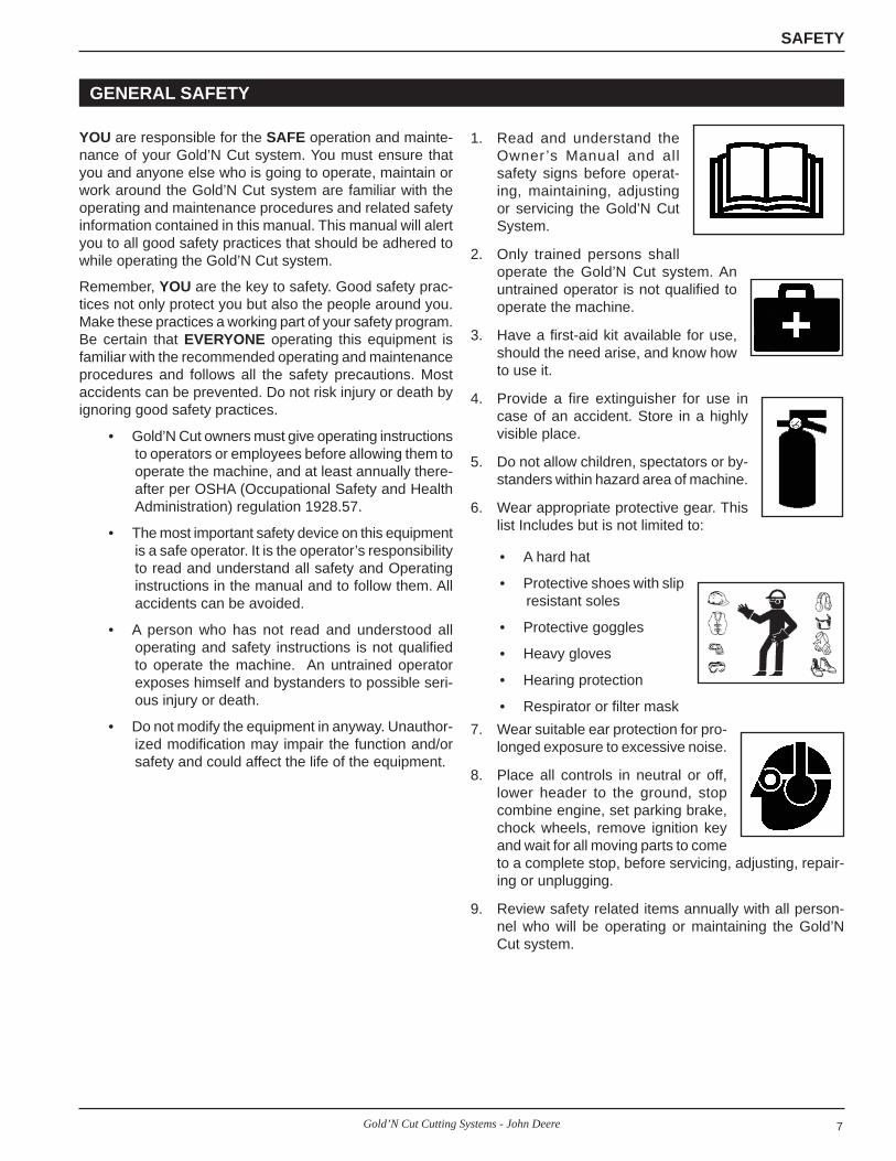
1. Read and understand the Owner ’s Manual and all safety signs before operat-ing, maintaining, adjusting or servicing the Gold’N Cut System.
2. Only trained persons shall operate the Gold’N Cut system. An untrained operator is not qualified to operate the machine.
3. Have a first-aid kit available for use, should the need arise, and know how to use it.
4. Provide a fire extinguisher for use in case of an accident. Store in a highly visible place.
5. Do not allow children, spectators or by-standers within hazard area of machine.
6. Wear appropriate protective gear. This list Includes but is not limited to:
• A hard hat
• Protective shoes with slip resistant soles
• Protective goggles
• Heavy gloves
• Hearing protection
• Respirator or filter mask7. Wear suitable ear protection for pro-
longed exposure to excessive noise.
8. Place all controls in neutral or off, lower header to the ground, stop combine engine, set parking brake, chock wheels, remove ignition key and wait for all moving parts to come to a complete stop, before servicing, adjusting, repair-ing or unplugging.
9. Review safety related items annually with all person-nel who will be operating or maintain ing the Gold’N Cut system.
SAFETY
8 Gold’N Cut Cutting Systems - John Deere
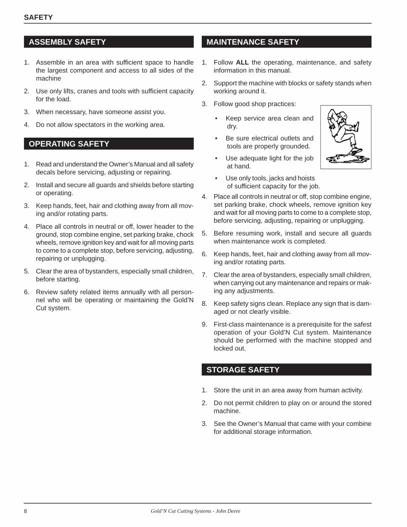
1. Follow ALL the operating, maintenance, and safety information in this manual.
2. Support the machine with blocks or safety stands when working around it.
3. Follow good shop practices:
• Keep service area clean and dry.
• Be sure electrical outlets and tools are properly grounded.
• Use adequate light for the job at hand.
• Use only tools, jacks and hoists of sufficient capacity for the job.
4. Place all controls in neutral or off, stop combine engine, set parking brake, chock wheels, remove ignition key and wait for all moving parts to come to a complete stop, before servicing, adjusting, repairing or unplugging.
5. Before resuming work, install and secure all guards when maintenance work is completed.
6. Keep hands, feet, hair and clothing away from all mov-ing and/or rotating parts.
7. Clear the area of bystanders, especially small children, when carrying out any maintenance and repairs or mak-ing any adjustments.
8. Keep safety signs clean. Replace any sign that is dam-aged or not clearly visible.
9. First-class maintenance is a prerequisite for the safest operation of your Gold’N Cut system. Maintenance should be performed with the machine stopped and locked out.
1. Read and understand the Owner’s Manual and all safety decals before servicing, adjusting or repairing.
2. Install and secure all guards and shields before starting or operating.
3. Keep hands, feet, hair and clothing away from all mov-ing and/or rotating parts.
4. Place all controls in neutral or off, lower header to the ground, stop combine engine, set parking brake, chock wheels, remove ignition key and wait for all moving parts to come to a complete stop, before servicing, adjusting, repairing or unplugging.
5. Clear the area of bystanders, especially small children, before starting.
6. Review safety related items annually with all person-nel who will be operating or maintaining the Gold’N Cut system.
OPERATING SAFETY
MAINTENANCE SAFETY
STORAGE SAFETY
ASSEMBLY SAFETY
1. Store the unit in an area away from human activity.
2. Do not permit children to play on or around the stored machine.
3. See the Owner’s Manual that came with your combine for additional storage information.
1. Assemble in an area with sufficient space to handle the largest component and access to all sides of the machine
2. Use only lifts, cranes and tools with sufficient capacity for the load.
3. When necessary, have someone assist you.
4. Do not allow spectators in the working area.
SAFETY

9Gold’N Cut Cutting Systems - John Deere
ASSEMBLY INSTRUCTIONSSection2
PRE-ASSEMBLYGOLD GUARDS HOLD DOWNS THUNDERBOLT
Clean any extra paint or built up material from the header platform before installing.
Remove any burrs and nicks from the mounting area.
Use a new knife assembly or a straight one (not badly worn) when aligning guards.
Do not use a hammer or pry up with a screwdriver to tighten the wear plates against the knifeback.
Shims should not be needed if mounting 7222 standard guards on header platforms that are 1/4” or thicker. Header platforms less than 1/4” will require shims.
When mounting 7229 standard guards on header platforms that are 3/8” or thicker, shims should not be needed. Header platforms less than 3/8” will require shims.
Sand off any rust or corrosion on sickle sections which may contact the wear pads.
Additional hold downs may be in-stalled to provide a more uniform hold down pressure.
When replacing hold downs, use no less than original number of OEM hold downs.
After hold downs have been ad-justed, run the system at full speed for a few minutes. Check for “hot spots” at hold down locations and adjust as needed.
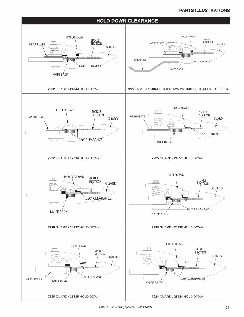
Typically hold downs are set at .020 inches from the sickle. However, in tougher cutting conditions, such as hay, the hold downs should be set closer (down to .005 inches).
Binding problems can result from insuffi cient clearance between the sickle and hold downs. Existing hold downs may need to be replaced with ones that allow more clearance for nuts.
On double drive systems, make sure to assemble both sickles correctly. See the ThunderBOLT section of the manual for correct assembly instructions.
Refer to the OEM owners manual for information on adjusting the sickles, setting the knife, and knife timing.
GENERAL INFORMATIONIn general, the Gold’N Cut is set up exactly the same as the OEM sickle system. The Gold’N Cut system usually will replace the OEM sickle, guards, and hold downs part for part. Use your packing slip for parts quantity information and guard descriptions. If all parts are not included contact your Crary Industries dealer.
The sickle head is not included in the system, but may be ordered extra from your Crary dealer. Normally, the original sickle head is used and can be bolted to the ThunderBOLT sickle.
In general, after determining a starting point, the hold downs are placed on every other guard. The clearance of the hold downs should be between .005” and .020”. The clearance should never be greater than .020. In hay, closer tolerances are required. In grain, the hold downs can be set at the upper end of the scale.
REMEMBERUse your packing
slip for parts and
quantity information.
If all parts are not
included, contact your
Crary Dealer.
Need help identifying parts??Finding out is easy!
Use the Parts List and Illustration section to determine what the parts look like and how many you need!
10 Gold’N Cut Cutting Systems - John Deere
ASSEMBLY
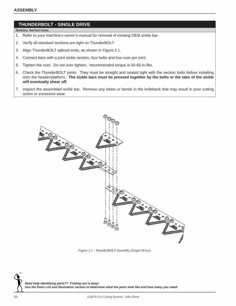
THUNDERBOLT - SINGLE DRIVEGENERAL INSTRUCTIONS:1. Refer to your machine’s owner’s manual for removal of existing OEM sickle bar.
2. Verify all standard sections are tight on ThunderBOLT.
3. Align ThunderBOLT spliced ends, as shown in Figure 2.1.
4. Connect bars with a joint sickle section, four bolts and four nuts per joint.
5. Tighten the nuts. Do not over tighten; recommended torque is 50-60 in./lbs.
6. Check the ThunderBOLT joints. They must be straight and seated tight with the section bolts before installing onto the header/platform. The sickle bars must be pressed together by the bolts or the tabs of the sickle will eventually shear off.
7. Inspect the assembled sickle bar. Remove any twists or bends in the knifeback that may result in poor cutting action or excessive wear.
Need help identifying parts?? Finding out is easy!Use the Parts List and Illustration section to determine what the parts look like and how many you need!
Figure 2.1 - ThunderBOLT Assembly (Single Drive).

11Gold’N Cut Cutting Systems - John Deere
ASSEMBLY
THUNDERBOLT - DOUBLE DRIVEGENERAL INSTRUCTIONS:1. Refer to your machine’s owners manual for removal of existing OEM sickle bar assemblies.
2. Verify all Gold’N Cut standard sections are tight.
3. Align sickle bar spliced ends.
4. On the left knife, connect the ThunderBOLT as illustrated in Figure 2.2. Four bolts and nuts are used on each joint.
5. On the right knife, two or more sickle bars may be used. One sickle bar uses the standard ThunderBOLT system as shown in Figure 2.1. The other sickle bar uses an overlap strap that is connected to the top of the section (Figure 2.2). Connect the appropriate ThunderBOLT sickle bar.
6. Tighten the nuts. Do not over tighten; recommended torque is 50-60 in./lbs.
7. Check the ThunderBOLT joints. They must be straight and seated tight with the section bolts before installing onto the header platform. The sickle bars must be pressed together by the bolts or the tabs of the sickle will eventually shear off.
8. Verify the overlap area (generally the top of the left knife assembly and the bottom of the right knife assembly—some machines may be opposite) is smooth to prevent interference. Figure 2.2 illustrates special right knife sections with countersunk holes on the bottom to allow a flush bolt head to fit underneath. The left knife’s special sections have countersunk holes on the top for a flush bolt head fit on the top side.
9. Inspect the assembled sickle bar. Remove any twists or bends in the knifeback that may result in poor cutting action or excessive wear.
Need help identifying parts?? Finding out is easy!Use the Parts List and Illustration section to determine what the parts look like and how many you need!
COUNTERSUNK BOLTS
Figure 2.2 - ThunderBOLT Assembly (Double Drive).
12 Gold’N Cut Cutting Systems - John Deere
ASSEMBLY
7222 GUARDSJOHN DEERE: 200, 600, 900 & QUICK TACH
GENERAL INSTRUCTIONS:1. Install new guards starting and working from left to right replacing the OEM guards with Crary Guards as you go.
Head area hold downs on John Deere systems start on the third full guard from the left hand side of the machine.
2. Install the wear plates, with the curled edge turned downward, to alternating guards beginning with the third full guard from the left hand side of the machine. Alternate the 6” and 12” wear plates for all series except 900D.
3. Attach hold downs above the wear plates starting with the head hold down and continuing with regular spring loaded hold downs. Remember, JD heads start at the third full guard. Do not tighten at this time. Use shims to adjust rear wear pad clearance to .020”.
4. Bolt knifeback to the knifehead. Recommended torque is 50-60 In-lbs. If necessary, bolt the ThunderBOLT to-gether at this time. Slide the sickle into the guards from the left side.
5. Guards may need adjustment to ensure the knife rests level on the platform.
6. Adjust wear plates snugly against the back of the knifeback.
7. Tighten guard bolts and torque to 30 Ft-lbs.
8. Using the adjustment bolts, position the heads of the hold downs to obtain .020” clearance between the top of the sections and the bottom of the wear pads. In tough cutting conditions, the hold downs can be adjusted down to .005”.
MODEL VARIATIONS:
TRIPLE GUARD: The triple guard is used on JD 200, 900, & Quick Tack headers. REMOVE THE OEM GUARD AND REPLACE WITH THE CRARY GUARD IN THE SAME LOCATION. Three triple guards are used on the JD 30 ft header.
THUNDERBOLT: None, one, or two ThunderBOLT splices will be used when mounting this Gold’N Cut system. When installing the ThunderBOLT, make sure to follow the ThunderBOLT assembly instruction in this manual. The sickle bars must be pressed together by the bolts or the tabs of the sickle will eventually shear off.
NOTES: Shims should not be needed if mounting 7222 standard guards on header platforms 1/4” or thicker. Header platforms less than 1/4” will require shims.
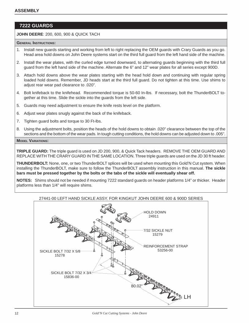
27441-00 LEFT HAND SICKLE ASSY. FOR KINGKUT JOHN DEERE 600 & 900D SERIES
80.02"
LH
REINFORCEMENT STRAP 53256-00
HOLD DOWN 24911
7/32 SICKLE NUT 15279
SICKLE BOLT 7/32 X 3/4 15836-00
SICKLE BOLT 7/32 X 5/8 15278

13Gold’N Cut Cutting Systems - John Deere
ASSEMBLY
7222 GUARDS -- JOHN DEERE 200, 600, 900, 900D & QUICK TACH
LEFT SECTION
3 POINT GUARD SECTION(NOT ON 600 SERIES)
SLIDE SICKLEIN HERE
GOLD GUARD7222
HOLD DOWN24911
WEAR PLATE (6")17329
WEAR PLATE (12")(NOT USED ON JD900D)16658
HOLD DOWN24344
3 POINT GUARD21228

14 Gold’N Cut Cutting Systems - John Deere
ASSEMBLY
7228 GUARDS w/HEAD GUARDSJOHN DEERE: 88, 120, 130, 135, 140, 188, 200, 230, 240, 580, 590, 780, 800, 830, 1209, 1214, 1219, 1380, 1424, 2250, 2270, 2280, 2320, 2360, 2420GENERAL INSTRUCTIONS:1. Install new guards starting and working from left to right replacing the OEM guards with Crary guards as you go.
Head Guards are positioned before the standard GOLD Guards.
2. Position hold downs, on alternating guards, beginning with the third full guard from the left hand side of the ma-chine. Start with the head hold down and continue with spring loaded hold downs.
3. Bolt guards and hold downs to the platform. Do not tighten. Use shims to adjust wear pads to .020”.
4. Bolt knifeback to the knifehead. Connect the ThunderBOLT(s) at this time. Recommended torque is 50-60 In-lbs. Slide the sickle into the guards from the left side.
5. Guards may need adjustment to ensure the knife rests level on the ledger surface.
6. Tighten guard bolts an torque to 52 Ft-lbs.
7. Using the adjustment bolts, position the heads of the hold downs to obtain .020” clearance between the top of the sections and the bottom of the wear pads. In tough cutting conditions, the hold downs can be set at .005”.
MODEL VARIATIONS:Head Guard: Up to three head guards are used. Check your packing slip for details on how many of these guards are used on your machine. The head guards are installed before the 7228 guards.
ThunderBOLT: Up to two ThunderBOLT splices will be used when mounting this Gold’N Cut system. When installing the Thun-derBOLT ,make sure to follow the ThunderBOLT assembly instructions in this manual. The sickle bars must be pressed together by the bolts or the tabs of the sickle will eventually shear off.
LEFT SECTION
HOLD DOWN24911
HOLD DOWN24338
HEAD GUARD22063
GOLD GUARD7228
SLIDE SICKLEIN HERE
15Gold’N Cut Cutting Systems - John Deere
ASSEMBLY
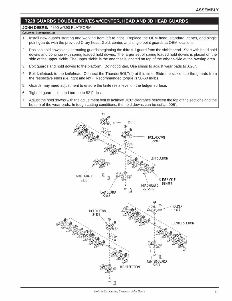
7228 GUARDS DOUBLE DRIVES w/CENTER, HEAD AND JD HEAD GUARDSJOHN DEERE: 4890 w/890 PLATFORMGENERAL INSTRUCTIONS:1. Install new guards starting and working from left to right. Replace the OEM head, standard, center, and single
point guards with the provided Crary head, Gold, center, and single point guards at OEM locations.
2. Position hold downs on alternating guards beginning the third full guard from the sickle head. Start with head hold downs and continue with spring loaded hold downs. The larger set of spring loaded hold downs is placed on the side of the upper sickle. The upper sickle is the one that is located on top of the other sickle at the overlap area.
3. Bolt guards and hold downs to the platform. Do not tighten. Use shims to adjust wear pads to .020”.
4. Bolt knifeback to the knifehead. Connect the ThunderBOLT(s) at this time. Slide the sickle into the guards from the respective ends (i.e. right and left). Recommended torque is 50-60 In-lbs.
5. Guards may need adjustment to ensure the knife rests level on the ledger surface.
6. Tighten guard bolts and torque to 52 Ft-lbs.
7. Adjust the hold downs with the adjustment bolt to achieve .020” clearance between the top of the sections and the bottom of the wear pads. In tough cutting conditions, the hold downs can be set at .005”.
CENTER SECTION
SLIDE SICKLEIN HEREHEAD GUARD
25355-12HEAD GUARD
22063
GOLD GUARD7228
HOLD DOWN24911
25615
HOLD DOWN24338
CENTER GUARD22877
HOLDER16305
LEFT SECTION
RIGHT SECTION

16 Gold’N Cut Cutting Systems - John Deere
ASSEMBLY
7228 GUARDS DOUBLE DRIVES w/CENTER, HEAD AND SINGLE POINT GUARDSJOHN DEERE: 300 AUGER PLATFORM FOR 3830, 3430 WINDROWER, MOWER/CONDITIONER 1525, 1600, HAY CONDITIONER 31, 36, 61, 66
GENERAL INSTRUCTIONS:
1. Install new guards starting and working from left to right. Replace the OEM head, standard, center, and single point guards with the provided Crary head, Gold, center, and single point guards at OEM locations.
2. Position hold downs on alternating guards beginning with the third full guard from the left hand side of the machine. Start on the ends with head hold downs and continue with spring loaded hold downs. Depending upon the model, head area hold downs may be used in the middle. On some models, two different spring loaded hold downs are used. On these models, the larger set of spring loaded hold downs is placed on the side of the upper sickle. The upper sickle is the one that is located on top of the other sickle at the overlap area.
3. Bolt guards and hold downs to the platform. Do not tighten. Use shims to adjust wear pads to .020”.
4. Bolt knifeback to the knifehead. Connect the ThunderBOLT(s) at this time. Recommended torque is 50-60 In-lbs. Slide the sickle into the guards from the respective ends (i.e. right and left).
5. Guards may need adjustment to ensure the knife rests level on the ledger surface.
6. Tighten guard bolts and torque to 52 Ft-lbs.
7. Adjust the hold downs with the adjustment bolt to achieve .020” clearance between the top of the sections and the bottom of the wear pads. In tough cutting conditions, the hold downs can be set at .005”.
MODEL VARIATIONS:
Head Guard: One to four head guards are used. Check your packing slip for details on how many of these guards are used on your machine. The head guards are installed before the 7228 guards.
Head Area Hold Downs: One or two head area hold downs are used. Check your packing slip for details on how many of these hold downs are used on your machine. Head area hold downs are installed before spring loaded hold downs at OEM locations.
Single Point Guards: Replace the Crary single point guard at the location where the OEM single point guard was removed. One to two single point guards are used.
Center Guards: Replace the Crary center guards at the location where the OEM center guard was removed. One to two center guards are used.
ThunderBOLT: One or two ThunderBOLT splices will be used when mounting this Gold’N Cut system. When install-ing the ThunderBOLT, make sure to follow the assembly instructions in this manual. The sickle sections must be pressed together by the bolts or the tabs of the sickle will eventually shear off.
17Gold’N Cut Cutting Systems - John Deere
ASSEMBLY
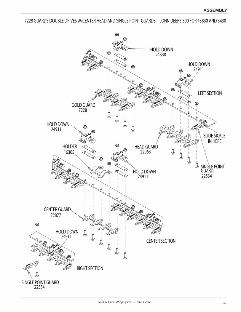
7228 GUARDS DOUBLE DRIVES W/CENTER HEAD AND SINGLE POINT GUARDS -- JOHN DEERE 300 FOR #3830 AND 3430
LEFT SECTION
CENTER SECTION
RIGHT SECTION
SLIDE SICKLEIN HERE
SINGLE POINT GUARD22534
HEAD GUARD22063
GOLD GUARD7228
HOLD DOWN24338
HOLD DOWN24911
HOLDER16305
HOLD DOWN24911
HOLD DOWN24911
CENTER GUARD22877
SINGLE POINT GUARD22534
HOLD DOWN24911

18 Gold’N Cut Cutting Systems - John Deere
PARTS LISTS & ILLUSTRATIONSSection3
NOTE: DOUBLE POINT SICKLES ARE NOT COMPATIBLE WITH GOLD’N CUT OR KINGKUT SYSTEMS.
JOHN DEERE COMBINESHEADER: 200, 900 & QUICK TACH
DESCRIPTION 13 FT. 15 FT. (200)
15 FT. (900) 16 FT. 18 FT. 20 FT. 22 FT. 24 FT. 25 FT. 30 FT.
GOLD’N CUT COMPLETE SYS-TEM (BC) 19388 19389 28086 19390 19391 19392 19393 19394 28779 19395
COMPLETE SICKLE 19358 19359 28084 19360 19361 19362 19363 19364 28777 19365-LEFT HAND SICKLE 28211 28211 28211 28211 28211 28211 28211 28211 28211 28211
-CENTER SICKLE - - - - 28212 28212 28212 28212 28212 28212 (2)
-RIGHT HAND SICKLE 28218 28215 28216 28213 28220 28219 28217 28214 28775 28218KINGKUT COMPLETE SYSTEM (KK) 27397 27398 27399 27401 27402 27404 27406 27408 27409 27411
COMPLETE SICKLE 27380 27381 27382 27384 27385 27387 27389 27391 27392 27394
-LEFT HAND SICKLE 27070-00
27070-00
27070-00
27070-00
27070-00
27070-00
27070-00
27070-00
27070-00
27070-00
-CENTER SICKLE - - - - 27071-00
27071-00
27071-00
27071-00
27071-00
27071-00 (2)
-RIGHT HAND SICKLE 27101-00
27102-00
27093-00
27094-00
27104-00
27100-00
27091-00
27093-00
27099-00
27101-00
PART # DESCRIPTION QTY QTY QTY QTY QTY QTY QTY QTY QTY QTY
7222 GUARD, GOLD 24 28 29 30 34 38 39 46 49 5521228 GUARD, 3-POINT 1 1 1 1 1 1 3 1 1 317203 SECTION, GOLD (BC) 50 58 60 62 70 78 86 94 100 11814765 SECTION, KINGKUT (KK) 49 57 59 61 69 77 85 93 99 11721553 SECTION, HALF-LH (BC) 1 1 1 1 1 1 1 1 1 122526 SECTION, HALF-LH (KK) 1 1 1 1 1 1 1 1 1 121554 SECTION, HALF-RH (BC) 1 1 1 1 1 1 1 1 1 1
17339 SECTION, H, S END-RH (KK) 1 1 1 1 1 1 1 1 1 1
24344 HOLD DOWN (SPRING LOADED) 11 13 14 14 16 18 20 22 24 29
24911 HOLD DOWN (SPRING LOADED HEAD) 1 1 1 1 1 1 1 1 1 1
17329 WEAR PLATE (6”) 6 7 8 8 9 10 11 12 13 1616658 WEAR PLATE (12”) 6 7 7 7 8 9 10 11 12 1422523 SHIM (.010) 24 28 30 30 34 38 42 46 50 6022524 SHIM (.024) 12 14 15 15 17 19 21 23 25 30
15378 BOLT, 3/8 X 1-1/4” CAR-RIAGE 27 31 31 33 37 41 45 49 51 59
15058 BOLT, 3/8 X 1-1/2” CAR-RIAGE 24 28 30 30 34 38 42 46 50 60
15051 NUT, 3/8” SERR. FLANGE 51 59 61 63 71 79 87 95 101 119
HEADER: 200, 900 & QUICK TACH
DESCRIPTION 13 FT. 15 FT. (200)
15 FT. (900) 16 FT. 18 FT. 20 FT. 22 FT. 24 FT. 30 FT.
DOUBLE POINT SICKLE 19366 19367 28085 19368 19369 19370 19371 19372 19373-LEFT HAND SICKLE 28221 28221 28221 28221 28221 28221 28221 28221 28221-CENTER SICKLE - - - - 28222 28222 28222 28222 28222 (2)-RIGHT HAND SICKLE 28228 28225 28226 28223 28230 28229 28227 23674 28228

19Gold’N Cut Cutting Systems - John Deere
PARTS LISTS
NOTE: CRARY GOLD GUARDS AND SICKLES ARE NOT COMPATIBLE WITH JOHN DEERE OEM 4” GUARDS & SICKLE.
JOHN DEERE COMBINESHEADER: 600 SERIES
DESCRIPTION 15 FT. 18 FT. 20 FT. 22 FT. 25 FT. 30 FT. 35 FT.GOLD’N CUT COMPLETE SYSTEM (BC) 27455 27456 27457 27458 27459 27460 27461 COMPLETE SICKLE 27448 27449 27450 27451 27452 27453 27454
-LEFT HAND SICKLE 27437-00 27437-00 27437-00 27437-00 27437-00 27437-00 27437-00-CENTER SICKLE - 28279 28279 28279 28279 28279 (2) 28279 (3)-RIGHT HAND SICKLE 27446-00 27442-00 27443-00 27445-00 27447-00 27444-00 27442-00
KINGKUT COMPLETE SYSTEM (KK) 27400 27403 27405 27407 27410 27412 27413 COMPLETE SICKLE 27383 27386 27388 27390 27393 27395 27396
-LEFT HAND SICKLE 27441-00 27441-00 27441-00 27441-00 27441-00 27441-00 27441-00
-CENTER SICKLE - 53257-00 53257-00 53257-00 53257-00 53257-00 (2)
53257-00 (3)
-RIGHT HAND SICKLE 53258-00 27087-00 27089-00 27092-00 27099-00 27091-00 27087-00PART # DESCRIPTION QTY QTY QTY QTY QTY QTY QTY
7222 GUARD, GOLD 29 35 39 43 49 59 6929295-12 GUARD, JD 600 LH 1 1 1 1 1 1 117202 SECTION, GOLD (BC) 52 64 72 80 92 112 13214765 SECTION, KINGKUT (KK) 52 64 72 80 92 112 13227439-00 SECTION, HEAD-LH (BC) 6 6 6 6 6 6 629294-00 SECTION, HEAD-AREA (KK) 6 6 6 6 6 6 617339 SECTION, H & S END-RH (BC) 1 1 1 1 1 1 127438-00 SECTION, H & S HEAD-LH 1 1 1 1 1 1 124344 HOLD DOWN (SPRING LOADED) (BC) 14 17 19 21 24 29 3424344 HOLD DOWN (SPRING LOADED) (KK) 12 15 17 19 22 27 3224911 HOLD DOWN (SPRING LOADED) (KK) 2 2 2 2 2 2 217329 WEAR PLATE (6”) (KK) 28 34 38 42 48 58 6817329 WEAR PLATE (6”) (BC) 8 9 10 11 12 15 1716658 WEAR PLATE (12”) (BC) 7 8 9 10 12 14 1722523 SHIM (.010) 28 34 38 42 48 58 6822524 SHIM (.024) 14 17 19 21 24 29 3415378 BOLT, 3/8 X 1-1/4” CARRIAGE 32 38 42 46 52 62 7215059 BOLT, 3/8 X 1-3/4” CARRIAGE 28 34 38 42 48 58 6815051 NUT, 3/8” SERR. FLANGE 60 72 80 88 100 120 14053256-00 12” REINFORCEMENT STRAP (KK) 1 1 1 1 1 1 1

20 Gold’N Cut Cutting Systems - John Deere
PARTS LISTS
JOHN DEERE COMBINESHEADER: JD900D SERIES
DESCRIPTION 25 FT. 30 FT. 36 FT.GOLD’N CUT COMPLETE SYSTEM (BC) 54183 54184 54185 COMPLETE SICKLE 27452 27453 54181
-LEFT HAND SICKLE 27437-00 27437-00 27437-00-CENTER SICKLE 28279 28279 (2) 28279 (3)-RIGHT HAND SICKLE 27447-00 27444-00 54252-00
KINGKUT COMPLETE SYSTEM (KK) 54186 54187 54188 COMPLETE SICKLE 27393 27395 54182
-LEFT HAND SICKLE 27441-00 27441-00 27441-00-CENTER SICKLE 53257-00 53257-00 (2) 53257-00 (3)-RIGHT HAND SICKLE 27099-00 27091-00 54251-00PART # DESCRIPTION QTY QTY QTY
7222 GUARD, GOLD 50 60 7231635-00 GUARD, JD RH END 1 1 129295-12 GUARD, JD 600 LH 1 1 117202 SECTION, GOLD (BC) 92 112 13714765 SECTION, KINGKUT (KK) 92 112 13727439-00 SECTION, HEAD-LH (BC) 6 6 629294-00 SECTION, HEAD-AREA (KK) 6 6 617339 SECTION, H & S END-RH (BC) 1 1 127438-00 SECTION, H & S HEAD-LH 1 1 124344 HOLD DOWN (SPRING LOADED) (BC) 24 29 3524344 HOLD DOWN (SPRING LOADED) (KK) 22 27 3324911 HOLD DOWN (SPRING LOADED) (KK) 3 3 324911 HOLD DOWN (SPRING LOADED) (BC) 1 1 117329 WEAR PLATE (6”) (KK) 25 30 3617329 WEAR PLATE (6”) (BC) 25 30 3622523 SHIM (.010) 50 60 7222524 SHIM (.024) 25 30 3615378 BOLT, 3/8 X 1-1/4” CARRIAGE 54 64 7615059 BOLT, 3/8 X 1-3/4” CARRIAGE 50 60 7215051 NUT, 3/8” SERR. FLANGE 104 124 14853256-00 12” REINFORCEMENT STRAP (KK) 1 1 1

21Gold’N Cut Cutting Systems - John Deere
PARTS LISTS
JOHN DEERE HAY MACHINESMOWERS: 5, 8, 9, 11, 37, 38, 39N, 47, 49, 50, 250, 350, 450
DESCRIPTION 7 FT.5, 8, 9, 11
9 FT.37, 38, 39,
39N
7 FT.47, 50, 250
9 FT.350, 450
GOLD’N CUT COMPLETE SYSTEM (TS) 19713 19714 19712 19956 COMPLETE SICKLE 19730 19731 19661 19955
-LEFT HAND SICKLE 19730 28199 19661 28203-RIGHT HAND SICKLE - 28458 - 28458
GOLD’N CUT COMPLETE SYSTEM (US) 28076 28077 28079 28080 COMPLETE SICKLE 28026 28075 28029 28078
-LEFT HAND SICKLE 28026 28201 28029 28542-RIGHT HAND SICKLE - 28202 - 28202
PART # DESCRIPTION QTY QTY QTY QTY QTY7228 GUARD, GOLD 12 16 12 1622063 GUARD, HEAD 3 3 3 322659 GUARD, SINGLE POINT 1 1 - -17370 SECTION, GOLD (TS) 28 36 28 3617369 SECTION, GOLD (US) 28 36 28 3621589 SECTION, HALF-LH (TS) - - 1 121590 SECTION, HALF-LH (US) - - 1 124338 HOLD DOWN (SPRING LOADED) 6 8 6 824911 HOLD DOWN (SPRING LOADED HEAD) 1 1 1 122523 SHIM (.010) 7 9 7 922524 SHIM (.024) 14 18 14 1815061 BOLT, 7/16 X 1-3/4” CARRIAGE 14 18 14 1815241 BOLT, 7/16 X 1-1/2” CARRIAGE 17 21 16 2015052 NUT, 7/16” SERR. FLANGE 31 39 30 38

22 Gold’N Cut Cutting Systems - John Deere
PARTS LISTS
JOHN DEERE HAY MACHINESMOWER/CONDITIONER: 1209 (9’), 1214 (12’, 14’), 1219 (9’), MID PIVOT-1380, 1424 (12’, 14’), 88, 120, 188, 200WINDROWER: 780, 800, 830, 2250, 2270, 2280, 2320, 2420 (12’-21’) AUGER PLATFORMS: 230, 240 (12’, 14’, 16 ‘) DRAPER PLATFORMS: 130, 135 (15’, 18’, 21’, 25)
DESCRIPTION 7 FT. 9 FT. 12 FT. 14 FT. 15 FT. 16 FT. 18 FT. 21 FT. 25 FT.GOLD’N CUT COMPLETE SYSTEM (BC) 25529 25530 25531 25532 25533 25534 25535 25536 25537 COMPLETE SICKLE 24758 24759 24760 24761 24762 24763 24764 24765 24766
-LEFT HAND SICKLE 24758 24756 24756 24756 24756 24756 24756 24756 24756-CENTER SICKLE - - - - - - 24744 24744 24744-RIGHT HAND SICKLE - 24767 24768 24769 24770 24771 24772 24773 24771
KINGKUT COMPLETE SYSTEM (TS) 19953 19628 19630 19632 19634 19636 19638 19640 28446 COMPLETE SICKLE 19952 19627 19629 19631 19633 19635 19637 19639 28445
-LEFT HAND SICKLE 19952 28203 28203 28203 28203 28203 28203 28203 28203-CENTER SICKLE - - - - - - 28432 28432 28432-RIGHT HAND SICKLE - 28200 28209 28207 28206 28205 28210 28208 28205
GOLD’N CUT COMPLETE SYSTEM (US) 28525 28527 28529 28531 28533 28535 28537 28539 28541 COMPLETE SICKLE 28524 28526 28528 28530 28532 28534 28536 28538 28540
-LEFT HAND SICKLE 28524 28542 28542 28542 28542 28542 28542 28542 28542-CENTER SICKLE - - - - - - 28543 28543 28543-RIGHT HAND SICKLE - 28551 28549 28547 28546 28544 28550 28548 28544
PART # DESCRIPTION QTY QTY QTY QTY QTY QTY QTY QTY QTY
7228 GUARD, GOLD 12 16 22 26 28 30 34 40 4722063 GUARD, HEAD 3 3 3 3 3 3 3 3 317318 SECTION, GOLD (BC) 28 36 48 56 60 64 72 84 9817370 SECTION, GOLD (TS) 28 36 48 56 60 64 72 84 9817369 SECTION, GOLD (US) 28 36 48 56 60 64 72 84 9821589 SECTION, HALF-LH (TS) 1 1 1 1 1 1 1 1 117339 SECTION, H & S END-RH (TS) 1 1 1 1 1 1 1 1 117884 SECTION, H & S END-RH (US) 1 1 1 1 1 1 1 1 124338 HOLD DOWN (SPRING LOADED) 6 8 11 13 14 15 17 20 23
24911 HOLD DOWN (SPRING LOADED HEAD) 1 1 1 1 1 1 1 1 1
22523 SHIM (.010”) 7 9 12 14 15 16 18 21 2422524 SHIM (.024”) 14 18 24 28 30 32 36 42 4815061 BOLT, 7/16 X 1-3/4” CARRIAGE 14 18 24 28 30 32 36 42 4815241 BOLT, 7/16 X 1-1/2” CARRIAGE 16 20 26 30 32 34 38 44 5215052 NUT, 7/16” SERR. FLANGE 30 38 50 58 62 66 74 86 100

23Gold’N Cut Cutting Systems - John Deere
PARTS LISTS
JOHN DEERE HAY MACHINESAUGER PLATFORM: 300 FOR #3830 AND #3430 WRMOWER/CONDITIONER: 31, 36, 61, 66, 1525, 1600
DESCRIPTION 12 FT.DOUBLE DRIVE
14 FT.DOUBLE DRIVE
16 FT.DOUBLE DRIVE
GOLD’N CUT COMPLETE SYSTEM (BC) 25538 25539 25540 COMPLETE SICKLE 24819 24820 24821
-LEFT HAND SICKLE 24826 24824 24822-RIGHT HAND SICKLE 24827 24825 24823
GOLD’N CUT COMPLETE SYSTEM (TS) 19960 19961 19962 COMPLETE SICKLE 19957 19958 19959
-LEFT HAND SICKLE 19967 19965 19963-RIGHT HAND SICKLE 19968 19966 19964
GOLD’N CUT COMPLETE SYSTEM (US) 28716 28717 28718 COMPLETE SICKLE 28713 28714 28715
-LEFT HAND SICKLE 28723 28721 28719-RIGHT HAND SICKLE 28724 28722 28720
PART # DESCRIPTION QTY QTY QTY7228 GUARD, GOLD 19 23 2722063 GUARD, HEAD 4 4 422534 GUARD, SINGLE POINT 2 2 222877 GUARD, CENTER 2 2 217318 SECTION, GOLD (BC) 42 50 5817370 SECTION, GOLD (TS) 42 50 5817369 SECTION, GOLD (US) 42 50 5817425 SECTION, GOLD (BOTTOM CSK) 3 3 317349 SECTION, H & S END-LH (TS) 1 1 117339 SECTION, H & S END-RH (TS) 1 1 117884 SECTION, H & S END-RH (US) 1 1 125963-00 SECTION, OVERLAP (SAWTOOTH) 3 3 324338 HOLD DOWN (SPRING LOADED) 9 11 1324911 HOLD DOWN (SPRING LOADED HEAD) 4 4 417431 OVERLAP STRAP 1 1 117427 SPACER 2 2 216305 HOLDER (JD) 1 1 122523 SHIM (.010) 28 16 1822524 SHIM (.024) (BC AND TS) 42 48 5421256 SHIM (.036) (BC AND TS) 32 36 4015061 BOLT, 7/16 X 1-3/4” CARRIAGE 28 32 3615241 BOLT, 7/16 X 1-1/2” CARRIAGE 22 28 3215052 NUT, 7/16” SERR. FLANGE 52 60 68

24 Gold’N Cut Cutting Systems - John Deere
PARTS LISTS
JOHN DEERE HAY MACHINESMOWER: 4890 W/890 PLATFORM
DESCRIPTION 14 FT.DOUBLE DRIVE
16 FT.DOUBLE DRIVE
18 FT.DOUBLE DRIVE
GOLD’N CUT COMPLETE SYSTEM (BC) 25350 25352 25354 COMPLETE SICKLE 25338 25340 25342
-LEFT HAND SICKLE 25328 25324 25334-LEFT HAND SICKLE - - 25335-RIGHT HAND SICKLE 25327 25323 25333-RIGHT HAND SICKLE - - 25332
GOLD’N CUT COMPLETE SYSTEM (TS) 25349 25351 25353 COMPLETE SICKLE 25337 25339 25341
-LEFT HAND SICKLE 25331 25344 25346-LEFT HAND SICKLE - - 25336-RIGHT HAND SICKLE 25329 25343 25345-RIGHT HAND SICKLE - - 25332
GOLD’N CUT COMPLETE SYSTEM (US) 29222 29223 29224 COMPLETE SICKLE 29219 29220 29221
-LEFT HAND SICKLE 29211-00 29212-00 29213-00-LEFT HAND SICKLE - - 25336-RIGHT HAND SICKLE 29214-00 29215-00 29216-00-RIGHT HAND SICKLE - - 29217-00
PART # DESCRIPTION QTY QTY QTY7228 GUARD, GOLD 22 26 3022063 GUARD, HEAD 4 4 425355-12 GUARD, HEAD 2 2 222877 GUARD, CENTER 1 1 117318 SECTION, GOLD (BC) 53 61 6917370 SECTION, GOLD (TS) 53 61 6617369 SECTIONS, GOLD (US) 50 58 6617425 SECTION, GOLD (BOTTOM CSK) (TS) 3 3 317349 SECTION, H & S END-LH 1 1 117339 SECTION, H & S END-RH (BC AND TS) 1 1 117884 SECTION, END (US) 1 1 125963-00 SECTION, OVERLAP (SAWTOOTH) 3 3 325615 ASSEMBLY, SPRING LOADED HOLD DOWN 5 6 724338 HOLD DOWN (SPRING LOADED) 5 6 724911 HOLD DOWN (SPRING LOADED HEAD) 4 4 425317 OVERLAP STRAP 1 1 116305 HOLDER (JD) 1 1 122523 SHIM (.010) 28 32 3615061 BOLT, 7/16 X 1-3/4” CARRIAGE 28 32 3615241 BOLT, 7/16 X 1-1/2” CARRIAGE 30 34 3815052 NUT, 7/16” SERR. FLANGE 58 66 74

25Gold’N Cut Cutting Systems - John Deere
PARTS LISTS
JOHN DEERE HAY MACHINESWINDROWER: JOHN DEERE 580, 590, 2360, 140
DESCRIPTION 12 FT. 14 FT. 15 FT. 16 FT. 18 FT. 21 FT. 25 FT. 30 FT. 36 FT.GOLD’N CUT COMPLETE SYSTEM (BC) 23961 23962 23963 23964 23965 23966 23967 23968 23969 COMPLETE SICKLE 23970 23971 23972 23973 23974 23975 23976 23977 23978
-LEFT HAND SICKLE 23950 23950 23950 23950 23950 23950 23950 23950 23950
-CENTER SICKLE - - - - 23951 23951 23951 23951 (2)
23951 (3)
-RIGHT HAND SICKLE 23954 23957 23958 23959 23952 23955 23960 23956 23953GOLD’N CUT COMPLETE SYSTEM (TS) 28945 28946 28947 28948 28949 28950 28951 28952 28966 COMPLETE SICKLE 28929 28930 28931 28932 28933 28934 28935 28936 28964
-LEFT HAND SICKLE 28908 28908 28908 28908 28908 28908 28908 28908 28908
-CENTER SICKLE - - - - 28909 28909 28909 28909 (2)
28909 (3)
-RIGHT HAND SICKLE 28911 28914 28915 28916 28910 28912 28917 28913 28962GOLD’N CUT COMPLETE SYSTEM (US) 28953 28954 28955 28956 28957 28958 28959 28960 28967 COMPLETE SICKLE 28937 28938 28939 28940 28941 28942 28943 28944 28965
-LEFT HAND SICKLE 28919 28919 28919 28919 28919 28919 28919 28919 28919-CENTER SICKLE - - - - 28920 28920 28920 28920 28920-RIGHT HAND SICKLE 28922 28925 28926 28927 28921 28923 28928 28924 28963
PART # DESCRIPTION QTY QTY QTY QTY QTY QTY QTY QTY QTY
7228 GUARD, GOLD 23 27 28 31 34 41 48 58 7022063 GUARD, HEAD 2 2 2 2 2 2 2 2 216918 SECTION, GOLD (BC) 48 56 58 64 70 83 99 118 14217877 SECTION, GOLD (TS) 48 56 58 64 70 83 99 118 14217878 SECTION, GOLD (US) 48 56 58 64 70 83 99 118 14223949 SECTION, HALF-LH (BC) 1 1 1 1 1 1 1 1 122786 SECTION, HALF-LH (TS) 1 1 1 1 1 1 1 1 117339 SECTION, H & S END-RH (TS) 1 1 1 1 1 1 1 1 117884 SECTION, H & S END-RH (US) 1 1 1 1 1 1 1 1 124338 HOLD DOWN (SPRING LOADED) 11 13 14 15 17 20 24 29 35
24911 HOLD DOWN (SPRING LOADED HEAD) 1 1 1 1 1 1 1 1 1
22523 SHIM (.010) 12 14 15 16 18 21 25 30 3621256 SHIM (.036) 24 28 30 32 36 42 50 60 72
15061 BOLT, 7/16 X 1-3/4” CARRIAGE (TS, US) 24 28 60 32 36 42 50 60 72
15082 BOLT, 7/16 X 2” CARRIAGE (BC) 24 28 60 32 36 42 50 60 7215241 BOLT, 7/16 X 1-1/2” CARRIAGE 26 30 60 34 36 44 50 60 7215052 NUT, 7/16” SERR. FLANGE 50 58 60 66 72 86 100 120 144

26 Gold’N Cut Cutting Systems - John Deere
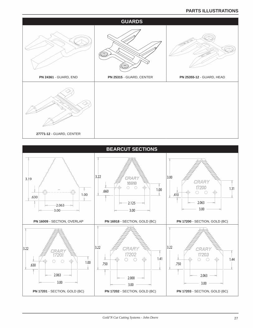
PARTS ILLUSTRATIONS
GUARDS
CRARY 7222
PAT. NO. 4651511
CRARY 7225
PAT. NO. 4651511
CRARY 7226
PAT. NO. 4651511
PN 7222 - GUARD, GOLD PN 7225 - GUARD, GOLD PN 7226 - GUARD, GOLD
CRARY 7228
PAT. NO. 4651511
PAT. NO. 4651511
CRARY 7229
PN 7228 - GUARD, GOLD PN 7229 - GUARD, GOLD PN 13454-00 - GUARD, SINGLE POINT
CRARY 21228
PAT. NO. 4651511
PAT. NO. 4651511
PAT. NO. 4651511
CRARY 7225
CRARY 7225
PN 21228 - GUARD, 3-POINT PN 21549 - GUARD, 3-POINT PN 21579 - GUARD, 3-POINT
CRARY 22063
PAT. NO. 4651511
CRARY 7225
PAT. NO. 4651511 CRARY 22063
PN 22063 - GUARD, HEAD PN 22064 - GUARD, HEAD PN 22534 - GUARD, SINGLE POINT
CRARY 7228
PN 22659 - GUARD, SINGLE POINT PN 22827 - GUARD, CENTER PN 22847 - GUARD, CENTER
27Gold’N Cut Cutting Systems - John Deere
PARTS ILLUSTRATIONS
BEARCUT SECTIONS
3.19
.630
2.063
3.00
1.00
3.22
3.00
1.00.660
2.125
3.00
3.00
1.31
.410
2.063
PN 16009 - SECTION, OVERLAP PN 16918 - SECTION, GOLD (BC) PN 17200 - SECTION, GOLD (BC)
3.22
3.00
1.00.630
2.063
3.22
3.00
1.41.750
2.000
3.22
3.00
1.44.750
2.063
PN 17201 - SECTION, GOLD (BC) PN 17202 - SECTION, GOLD (BC) PN 17203 - SECTION, GOLD (BC)
GUARDS
PN 24361 - GUARD, END PN 25315 - GUARD, CENTER PN 25355-12 - GUARD, HEAD
27771-12 - GUARD, CENTER
28 Gold’N Cut Cutting Systems - John Deere
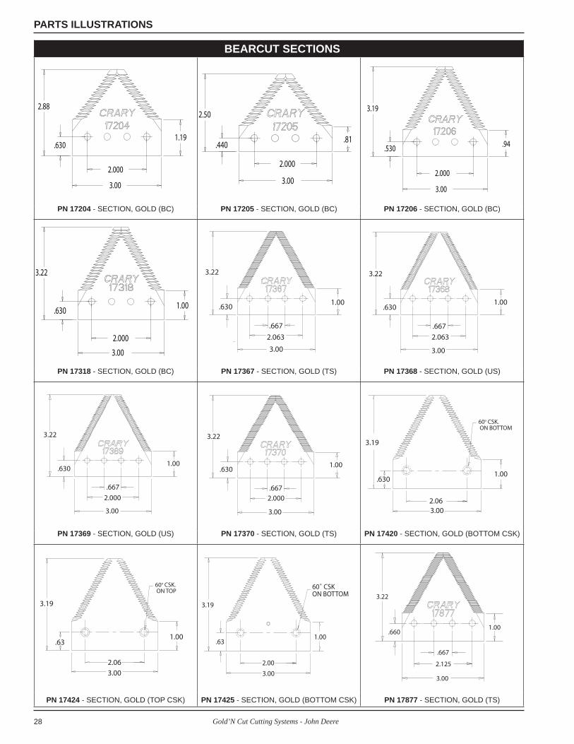
PARTS ILLUSTRATIONS
BEARCUT SECTIONS
2.88
3.00
1.19.630
2.000
2.50
3.00
.81.440
2.000
3.19
3.00
.94.530
2.000
PN 17204 - SECTION, GOLD (BC) PN 17205 - SECTION, GOLD (BC) PN 17206 - SECTION, GOLD (BC)
3.22
3.00
1.00.630
2.000
3.22
.630
.667
2.063
3.00
1.00
3.22
.630
.667
2.063
3.00
1.00
PN 17318 - SECTION, GOLD (BC) PN 17367 - SECTION, GOLD (TS) PN 17368 - SECTION, GOLD (US)
3.22
.630
.667
2.000
3.00
1.00
3.22
.630
.6672.000
3.00
1.00
3.19
.630
2.063.00
1.00
60o CSK. ON BOTTOM
PN 17369 - SECTION, GOLD (US) PN 17370 - SECTION, GOLD (TS) PN 17420 - SECTION, GOLD (BOTTOM CSK)
60o CSK. ON TOP
3.19
.63
2.06
3.00
1.00
60˚ CSKON BOTTOM
1.00
3.00
2.00
.63
3.19
1.00
3.00
2.125
.667
.660
3.22
PN 17424 - SECTION, GOLD (TOP CSK) PN 17425 - SECTION, GOLD (BOTTOM CSK) PN 17877 - SECTION, GOLD (TS)

29Gold’N Cut Cutting Systems - John Deere
PARTS ILLUSTRATIONS
BEARCUT SECTIONS
1.00
3.00
2.125
.667
.660
3.22 3.22
3.00
1.41.750
.5002.000
3.22
2.063
3.00
.63
PN 17878 - SECTION, GOLD (US) PN 24549 - SECTION, HEAD (BC) (TOP CSK) PN 24745 - SECTION, HEAD (US)
3.22
2.063
3.00
.63
3.22
3.00
1.00.660
2.125
3.19
2.063
.630
2.0002.125
3.00
PN 24746 - SECTION, HEAD (US) PN 24981 - SECTION, GOLD (BC) (TOP CSK) PN 25963-00 - SECTION, OVERLAP (SAW-TOOTH)
3.22
1.000
3.00
.75.410
2.063
3.00
3.00
1.31
.630
2.063
3.25
3.00
1.06
PN 27439-00 - HEAD-LH (BC) PN 29029 - SECTION, HEAD (BC) PN 29030 - SECTION, HEAD (BC)
.63
3.00
2.00
3.22
.63
2.00
3.00
3.22
.63
3.00
2.00
3.22
PN 29255-00 - SECTION, HEAD (BC) PN 29256-00 - SECTION, HEAD (TS) PN 29257-00 - SECTION, HEAD (US)

30 Gold’N Cut Cutting Systems - John Deere
PARTS ILLUSTRATIONS
KINGKUT SECTIONS
1.219
3.00
3.250
.660
2.0342.063
3.00
3.250
.6601.219
3.250
.482
.354 + .005
2.031
.670
60o CSK.ON BOTTOM
PN 14765 - SECTION, KINGKUT PN 27066-00 - SECTION, KINGKUT HEAD-LH
PN 27106-00 - SECTION, KINGKUT (BOT-TOM CSK)
60o CSK.ON TOP
3.250
2.031
.354 + .005
.670
.482
.67
2.99
1.000
3.25
PN 27107-00 - SECTION, KINGKUT (TOP CSK)
PN 27440-00 - SECTION, KINGKUT HEAD-LH

31Gold’N Cut Cutting Systems - John Deere
PARTS ILLUSTRATIONS
HALF SECTIONS
1.88
1.000
2.88
.6301.19
2.00
1.000
3.22
.7501.41
2.001.000
3.22
1.41.750
1.97
1.000
3.22
.750
PN 17336 - HALF-RH PN 17337 - HALF-RH PN 17338 - HALF-LH PN 21553 - HALF-LH
1.97
1.000
3.22
.750
1.97
1.000
3.00
.410
3.25
.63
1.0002.00
3.19
.63
1.0002.00
PN 21554 - HALF-RH PN 21556 - HALF-RH PN 21589 - HALF-LH (TS) PN 21590 - HALF-LH (US)
1.75
1.000
2.88
.630
3.19
.63
1.0001.88
3.25
.63
1.0001.97
3.22
.63
1.0001.63
PN 21767 - HALF-LH PN 22525 - HALF-RH PN 22526 - HALF-LH PN 22618 - HALF-LH
3.19
.66
1.63
.875
2.00
1.000
.63
3.19
2.00
1.000
.63
3.19 3.19
.63
1.0002.00
PN 22786 - HALF-LH (TS) PN 22834 - HALF-RH (TS) PN 22835 - HALF-RH (US) PN 22836 - HALF-LH (TS)

32 Gold’N Cut Cutting Systems - John Deere
PARTS ILLUSTRATIONS
HALF SECTIONS
3.19
.63
1.0002.00 1.63
.875
3.22
.660
2.00
1.000
.63
3.22
1.97
1.063
3.22
.660
PN 22837 - HALF-LH (US) PN 23949 - HALF-LH PN 24805 - HALF-RH (BC) PN 24979 - HALF-LH
1.97
1.063
3.22
.660 .410
1.971.000
3.00
.630
1.97
1.000
3.22
PN 24980 - HALF-RH PN 29027 - HALF-HEAD PN 29028 - HALF-HEAD
H & S / DOUBLE POINT SECTIONS
3.00
3.25
1.19.630
2.00
1.47
3.00
3.25
1.19.630
2.06
1.471.00
.63
2.063.75
.94
1.311.63
3.19
PN 17207 - SECTION, DOUBLE POINT END PN 17208 - SECTION, DOUBLE POINT PN 17339 - H & S END-RH (TS)
3.19
1.631.31
.94 2.063.75
.631.00
1.00 1.311.63
3.75
3.19
.625
2.06 .9375
3.19
1.000
3.75
.63
PN 17349 - H & S END-LH (TS) PN 17884 - SECTION, H & S END-RH (US) PN 27438-00 - H & S HEAD-LH

33Gold’N Cut Cutting Systems - John Deere
PARTS ILLUSTRATIONS
WEAR PLATES
PN 16658 - WEAR PLATE (12”) PN 17329 - WEAR PLATE (6”) PN 24261 - WEAR PLATE, OFFSET (6”)
PN 24892-12 - PLATE, HD/WEAR (SHORT) PN 24893-12 - PLATE, HD/WEAR (LONG) PN 27642-00 - WEAR PLATE, OFFSET (6”)
HOLD DOWNS
5.88
PN 17214 - HOLD DOWN CLIP PN 17418 - HIGH HOLD DOWN CLIP PN 23621 - HOLD DOWN PLATE (SHORT)
8.88
1557723395
1217717434
15490
12195
12165
15491
15577
23395
17435
15490
12177
12194
12156
15491
PN 23652 - HOLD DOWN PLATE (LONG) PN 24335 - HOLD DOWN (7/16” BASE) PN 24337 - HOLD DOWN (3/8” BASE)

34 Gold’N Cut Cutting Systems - John Deere
PARTS ILLUSTRATIONS
HOLD DOWNS15577
23395
1217717434
1549012195
12166
15491
15577
12177
23395
17434
15490
12165
15491
12194
15577
12177
23395
17435
15490 12195
15491
PN 24338 - HOLD DOWN (7/16” BASE) PN 24344 - HOLD DOWN (3/8” BASE) PN 24351 - HOLD DOWN (7/16” BASE)
15577
12523
17434 12177
15490
1252212165
15491
1557723395
1217717434
15490
12195
12156 15491
1557712523
1217717435
1252215490
12165 15491
PN 24911 - HEAD HOLD DOWN (3/8” BASE) PN 25347 - HOLD DOWN (7/16” BASE) PN 25348 -HEAD HOLD DOWN (3/8” BASE)
15577
12523
1217712848-00
1549012522
12165
15491
15577
23395
1217712848-00
15490 12195
1215615491
15577
23395
1217717434
1219415490
1216615491
PN 25454 -HEAD HOLD DOWN (7/16” BASE) PN 25615 - HOLD DOWN (7/16” BASE) PN 25724 - HOLD DOWN (3/8” BASE)
15577
23395
12848-00
15490
12156
15491
12194
12177
PN 27994 - HOLD DOWN (3/8” BASE)
35Gold’N Cut Cutting Systems - John Deere
PARTS ILLUSTRATIONS
HOLD DOWN CLEARANCE
GUARD
HOLD DOWN
.020" CLEARANCE
WEAR PLATESICKLESECTION
KNIFE BACK
7222 GUARD / 24344 HOLD DOWN 7222 GUARD / 24344 HOLD DOWN W/ SKID SHOE (JD 600 SERIES)
GUARD
HOLD DOWN
WEAR PLATE
SICKLESECTION
.020" CLEARANCE
GUARD
HOLD DOWN
SICKLESECTION
.020" CLEARANCE
WEAR PLATE
KNIFE BACK
7222 GUARD / 17214 HOLD DOWN 7225 GUARD / 24351 HOLD DOWN
SICKLESECTION
HOLD DOWN
GUARD
.020" CLEARANCE
KNIFE BACK
GUARD
HOLD DOWN
SICKLESECTION
.020" CLEARANCEKNIFE BACK
7226 GUARD / 24337 HOLD DOWN 7228 GUARD / 24338 HOLD DOWN
GUARD
HOLD DOWN
SICKLESECTION
OEM SPACER.020" CLEARANCE
KNIFE BACK
GUARD
HOLD DOWN
SICKLESECTION
.020" CLEARANCEKNIFE BACK
7228 GUARD / 25615 HOLD DOWN 7228 GUARD / 25724 HOLD DOWN
GUARD
HOLD DOWN
WEAR PLATE
SICKLESECTION
KNIFE BACK
.020" CLEARANCESKID SHOE

36 Gold’N Cut Cutting Systems - John Deere
PARTS ILLUSTRATIONS
HOLD DOWN CLEARANCE
GUARD
SICKLESECTION
HOLD DOWN
WEAR PLATE
KNIFE BACK
.020" CLEARANCE .020" CLEARANCE
KNIFE BACK
GUARD
SICKLESECTION
HOLD DOWN
WEAR PLATE
7229 GUARD / 24335 HOLD DOWN 7229 GUARD / 24344 HOLD DOWN
GUARD
HOLD DOWNSICKLESECTIONOFFSET
WEAR PLATE
SKID SHOE
KNIFE BACK
.020" CLEARANCE
7229 GUARD / 25615 HOLD DOWN W/SKID SHOE (CASE 1020)
37Gold’N Cut Cutting Systems - John Deere
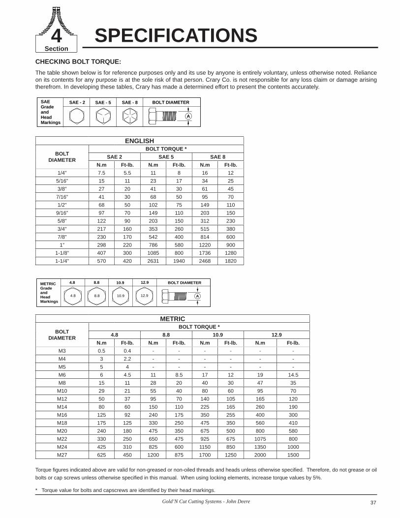
CHECKING BOLT TORQUE:The table shown below is for reference purposes only and its use by anyone is entirely voluntary, unless otherwise noted. Reliance on its contents for any purpose is at the sole risk of that person. Crary Co. is not responsible for any loss claim or damage arising therefrom. In developing these tables, Crary has made a determined effort to present the contents accurately.
Torque figures indicated above are valid for non-greased or non-oiled threads and heads unless otherwise specified. Therefore, do not grease or oil bolts or cap screws unless otherwise specified in this manual. When using locking elements, increase torque values by 5%.
* Torque value for bolts and capscrews are identifi ed by their head markings.
ENGLISH
BOLTDIAMETER
BOLT TORQUE *SAE 2 SAE 5 SAE 8
N.m Ft-lb. N.m Ft-lb. N.m Ft-lb.1/4” 7.5 5.5 11 8 16 12
5/16” 15 11 23 17 34 253/8” 27 20 41 30 61 45
7/16” 41 30 68 50 95 701/2” 68 50 102 75 149 110
9/16” 97 70 149 110 203 1505/8” 122 90 203 150 312 2303/4” 217 160 353 260 515 3807/8” 230 170 542 400 814 6001” 298 220 786 580 1220 900
1-1/8” 407 300 1085 800 1736 12801-1/4” 570 420 2631 1940 2468 1820
METRIC
BOLTDIAMETER
BOLT TORQUE *4.8 8.8 10.9 12.9
N.m Ft-lb. N.m Ft-lb. N.m Ft-lb. N.m Ft-lb.M3 0.5 0.4 - - - - - -M4 3 2.2 - - - - - -M5 5 4 - - - - - -M6 6 4.5 11 8.5 17 12 19 14.5M8 15 11 28 20 40 30 47 35
M10 29 21 55 40 80 60 95 70M12 50 37 95 70 140 105 165 120M14 80 60 150 110 225 165 260 190M16 125 92 240 175 350 255 400 300M18 175 125 330 250 475 350 560 410M20 240 180 475 350 675 500 800 580M22 330 250 650 475 925 675 1075 800M24 425 310 825 600 1150 850 1350 1000M27 625 450 1200 875 1700 1250 2000 1500
SAE - 8SAE - 2
A
SAE - 5SAEGradeandHeadMarkings
BOLT DIAMETER
10.94.8
A
8.8METRICGradeandHeadMarkings
BOLT DIAMETER12.9
4.8 8.8 10.9 12.9
SPECIFICATIONSSection4

38 Gold’N Cut Cutting Systems - John Deere

39Gold’N Cut Cutting Systems - John Deere

Crary Industries237 12th St. NW • P.O. Box 849
West Fargo, ND 58078-0849(701)282-5520 • FAX: (701)282-9522
www.crary.com