Embed Size (px)
Citation preview
CR
AN
E C
ON
TR
OL
C
LA
SS
700
4
Crane Control Class 7004
Catalog
17
CONTENTS
Description . . . . . . . . . . . . . . . . . . . . . . . . . . . . . . . . . . . . . . . . . . . . . . . . . . . . .PagePricing Information . . . . . . . . . . . . . . . . . . . . . . . . . . . . . . . . . . . . . . . . . . . . . . . . . 110Application Data . . . . . . . . . . . . . . . . . . . . . . . . . . . . . . . . . . . . . . . . . . . . . . . . . . . 111Dimensions and Weights . . . . . . . . . . . . . . . . . . . . . . . . . . . . . . . . . . . . . . . . . . . . 114
Crane Control Class 7004Type M Line-Arc® DC Contactors
CR
AN
E C
ON
TR
OL
C
LA
SS
700
4
© 2003 The Electric Controller & Mfg. Co., LLC All Rights Reserved
1101/17
SCH B,C
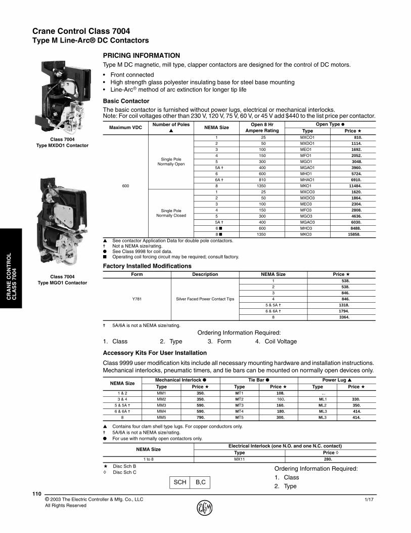
PRICING INFORMATIONType M DC magnetic, mill type, clapper contactors are designed for the control of DC motors.
• Front connected• High strength glass polyester insulating base for steel base mounting• Line-Arc� method of arc extinction for longer tip life
Basic ContactorThe basic contactor is furnished without power lugs, electrical or mechanical interlocks.Note: For coil voltages other than 230 V, 120 V, 75 V, 60 V, or 45 V add $440 to the list price per contactor.
▲ See contactor Application Data for double pole contactors.✝ Not a NEMA size/rating.● See Class 9998 for coil data.■ Operating coil forcing circuit may be required; consult factory.
✝ 5A/6A is not a NEMA size/rating.
Ordering Information Required:1. Class 2. Type 3. Form 4. Coil Voltage
Accessory Kits For User Installation
Class 9999 user modification kits include all necessary mounting hardware and installation instructions. Mechanical interlocks, pneumatic timers, and tie bars can be mounted on normally open devices only.
▲ Contains four clam shell type lugs. For copper conductors only.✝ 5A/6A is not a NEMA size/rating.● For use with normally open contactors only.
Ordering Information Required:
1. Class2. Type
Maximum VDCNumber of Poles
▲NEMA Size
Open 8 HrAmpere Rating
Open Type ●Type Price a
600
Single Pole Normally Open
1 25 MXCO1 810.
2 50 MXDO1 1114.
3 100 MEO1 1692.
4 150 MFO1 2052.
5 300 MGO1 3048.
5A ✝ 400 MGAO1 3960.
6 600 MHO1 5724.
6A ✝ 810 MHAO1 6910.
8 1350 MKO1 11484.
Single Pole Normally Closed
1 25 MXCO3 1620.
2 50 MXDO3 1864.
3 100 MEO3 2304.
4 150 MFO3 2808.
5 300 MGO3 4636.
5A ✝ 400 MGAO3 6030.
6 ■ 600 MHO3 8488.
8 ■ 1350 MKO3 15858.
Factory Installed ModificationsForm Description NEMA Size Price a
Y781 Silver Faced Power Contact Tips
1 538.
2 538.
3 846.
4 846.
5 & 5A ✝ 1318.
6 & 6A ✝ 1794.
8 3364.
NEMA SizeMechanical Interlock ● Tie Bar ● Power Lug ▲Type Price a Type Price a Type Price a
1 & 2 MM1 350. MT1 108. ...3 & 4 MM2 350. MT2 160. ML1 330.
5 & 5A ✝ MM3 590. MT3 160. ML2 350.
6 & 6A ✝ MM4 590. MT4 180. ML3 414.
8 MM5 790. MT5 300. ML3 414.
NEMA SizeElectrical Interlock (one N.O. and one N.C. contact)
Type Price h1 to 8 MX11 280.
Class 7004 Type MXDO1 Contactor
Class 7004 Type MGO1 Contactor
a Disc Sch Bh Disc Sch C
Crane Control Class 7004Type M Line-Arc® DC Contactors
CR
AN
E C
ON
TR
OL
C
LA
SS
700
4
1111/17 © 2003 The Electric Controller & Mfg. Co., LLC
All Rights Reserved
APPLICATION DATA
Ratings are based on 40 °C (104 °F), per NEMA standards.
Mounting
The Type M contactor with its insulated base can be mounted directly on uninsulated steel panels, angle iron frames, etc. The contactors are completely front-connected.
Wiring
Size 1 through 5A Type M contactors have a wire accessway in the base for convenient out-of-the-way routing of cables and control wires. Size 6 through 8 contactors have a flat mounting base. Power connections to the NEMA Sizes 3 through 8 contactors can be made from either side.
Coil Data
DC operating coils are designed in accordance with NEMA standards to withstand 110% of rated voltage continuously and to operate the contactor successfully at 80% of rated voltage. Standard coil voltages are 120 VDC and 240 VDC. For other available coil voltages, refer to the Class 9998 Coil Data Catalog Sheet.
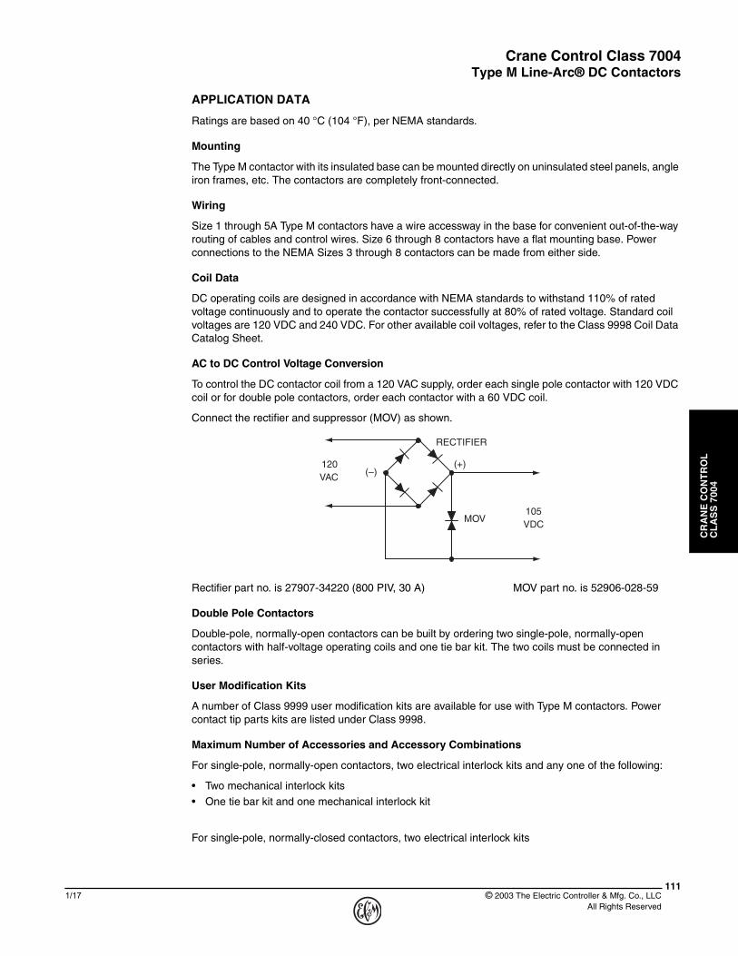
AC to DC Control Voltage Conversion
To control the DC contactor coil from a 120 VAC supply, order each single pole contactor with 120 VDC coil or for double pole contactors, order each contactor with a 60 VDC coil.
Connect the rectifier and suppressor (MOV) as shown.
Rectifier part no. is 27907-34220 (800 PIV, 30 A) MOV part no. is 52906-028-59
Double Pole Contactors
Double-pole, normally-open contactors can be built by ordering two single-pole, normally-open contactors with half-voltage operating coils and one tie bar kit. The two coils must be connected in series.
User Modification Kits
A number of Class 9999 user modification kits are available for use with Type M contactors. Power contact tip parts kits are listed under Class 9998.
Maximum Number of Accessories and Accessory Combinations
For single-pole, normally-open contactors, two electrical interlock kits and any one of the following:
• Two mechanical interlock kits
• One tie bar kit and one mechanical interlock kit
For single-pole, normally-closed contactors, two electrical interlock kits
(+)(–)
RECTIFIER
MOV
120
105
VAC
VDC
Crane Control Class 7004Type M Line-Arc® DC Contactors
CR
AN
E C
ON
TR
OL
C
LA
SS
700
4
© 2003 The Electric Controller & Mfg. Co., LLC All Rights Reserved
1121/17
APPLICATION DATA
Electrical Interlocks
Control circuit interlocks are available in units of one normally open and one normally closed contacts. On each single pole normally open and normally closed contactor a maximum of two interlock kits can be mounted. Interlock kits include the movable and stationary contacts plus all necessary hardware for mounting.
Electrical interlocks are rated in accordance with NEMA Standard ICS- 2-125 (A600 and N600 Table Ratings).
▲ Make and break ratings apply for double-throw contacts only when both the normally open and normally closed contacts are connected to the same polarity.
Mechanical Interlock
A horizontal mechanical interlock is mounted between two single pole normally open or double pole tied normally open contactors mounted side by side. This interlock prevents the two contactors from operating simultaneously.
Lugs
Type M contactors are furnished without power lugs. A kit is available consisting of lugs and hardware for mounting on Size 3 and larger contactors. No power lug kits are available for the NEMA Size 1 and 2 contactors. These contactors are designed to use lugs supplied by the user.
▲ Contains four clam shell type lugs. For copper conductors only.
Power Contact Tips
A Class 9998 power contact tips part kit consists of movable and stationary contact tips with necessary mounting hardware for two single pole contactors. Consult Catalog Section 9998 for additional information.
Copper contact tips are standard. Silver-faced contact tips are available and are recommended for applications where the contactors remain closed for long periods of time. Silver-faced contact tips are standard on crane manual-magnetic disconnect switches.
Tie Bar
Applications requiring double pole Type M contactors can be met by supplying single pole normally open only contactors with tie bars. The tie bar is made from an insulating material and connects the armatures of the contactors together. For double pole contactors, it is recommended that the operating coils be connected in series. Each coil should be rated for one half of system voltage. See Catalog Section 9999, page 160, for additional information.
A600Maximum
Continuous Amperes
Maximum Make and Break Current Amperes ▲
120V 240V 480V 600V
Make Break Make Break Make Break Make BreakAC 10 60 6 30 3 15 1.5 12 1.2
N600Maximum
Continuous Amperes
Maximum Make and Break Current Amperes ▲
125V 250V 600V
Make Break Make Break Make BreakDC 10 2.2 2.2 1.1 1.1 0.4 0.4
Lug Wire Capacity
Lug Type ▲ Minimum Wire Size Maximum Wire Size
ML1 Number 8 Number 00
ML2 Number 0 300 MCM
ML3 250 MCM 500 MCM
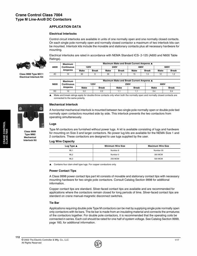
Class 9999 Type MX11Electrical Interlock Kit
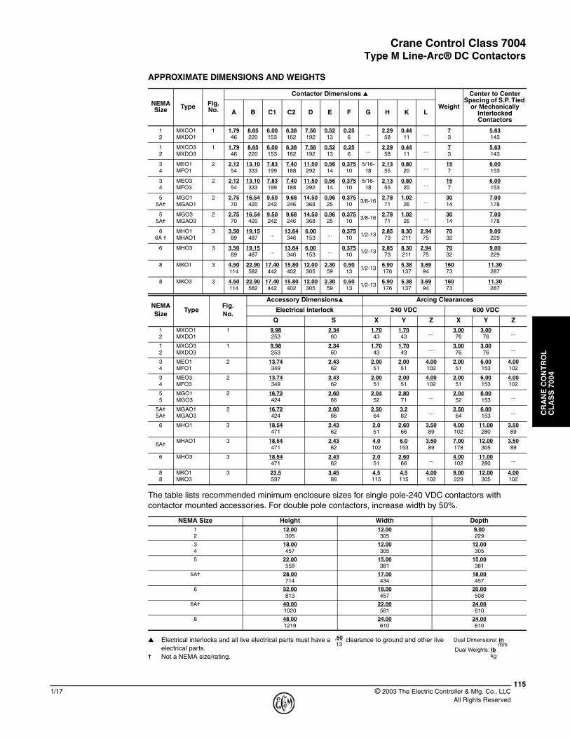
Class 9999Type MM2
MechanicalInterlock Kit

Crane Control Class 7004Type M Line-Arc® DC Contactors
CR
AN
E C
ON
TR
OL
C
LA
SS
700
4
1131/17 © 2003 The Electric Controller & Mfg. Co., LLC
All Rights Reserved
APPLICATION DATA
Class 9999 AI1 Arc Suppressor
The Class 9999 AI1 arc suppressor is designed to reduce arcing of pilot devices in DC inductive control circuits of 250 VDC or less.
The AI1 arc suppressor will limit the inductive voltage surge to a maximum of 600 VDC when applied in accordance with the application chart. When applying the arc suppressor to a circuit, two factors must be considered, the current drawn by the inductive load and the number of times per minute that the load will be interrupted. Once these two factors are determined, the application is checked against the application chart. The chart shows the maximum interruptions per minute that the arc suppressor can handle at a given current. As long as an application falls below the curve, the arc suppressor will handle the load. The arc suppressor is connected in parallel with the inductive load and is in the circuit at all times.
Application Chart for AI1 Arc Suppressor
Approximate Dimensions And Weights
Ordering Information Required:
1. Class 9999
2. Type AI1
Type PriceAI1 360.
10
CURRENT IN AMPERES
PE
RM
ISS
IBL
E IN
TE
RR
UP
TIO
NS
PE
R M
INU
TE
0.4 0.5 0.6 0.7 0.8 0.9 1.0 1.1 1.2 1.3 1.4
20
30
40
50
60
L = 11H
L = 20H
57
111
25
49
42 76
6.3
95
2.25
4.38
1.00
1.93
1.65 3.00
0.25
3.75
Clearance for (2)1/4" mtg. screws
mmDual Dimensions: inches
Net Weight – 1 lb (0.45 kg)
Class 9999Type AI1
Arc Suppress

Crane Control Class 7004Type M Line-Arc® DC Contactors
CR
AN
E C
ON
TR
OL
C
LA
SS
700
4
© 2003 The Electric Controller & Mfg. Co., LLC All Rights Reserved
1141/17
APPROXIMATE DIMENSIONS
C2C1
E
K
D
X
Y
Arcing clearancezoneH A
S S
Q
B
for screw "F"2 Mtg. holes
Figure 1
NEMA SIZES 1, 2SPNO AND SPNC
C1C2
Z E
K
D
X
Y
Arcing clearancezone
4 "G" tappedholesMain Terminals
2 Mtg. holesfor screw "F"
Q
B
A A
H H
S S
Figure 2
NEMA SIZES 3, 4, & 5SPNO AND SPNC
SIZE 5ASPNO AND SPNC
A AL
K
Q B D
S S
H H
4 Mtg. holesfor screw "F"
C1
C2
E Z X
Y
4 "G" tappedholesMain Terminal
Arcing clearancezone
Figure 3
NEMA SIZES 6, 8SPNO AND SPNCAND SIZE 6A SPNO
Crane Control Class 7004Type M Line-Arc® DC Contactors
CR
AN
E C
ON
TR
OL
C
LA
SS
700
4
1151/17 © 2003 The Electric Controller & Mfg. Co., LLC
All Rights Reserved
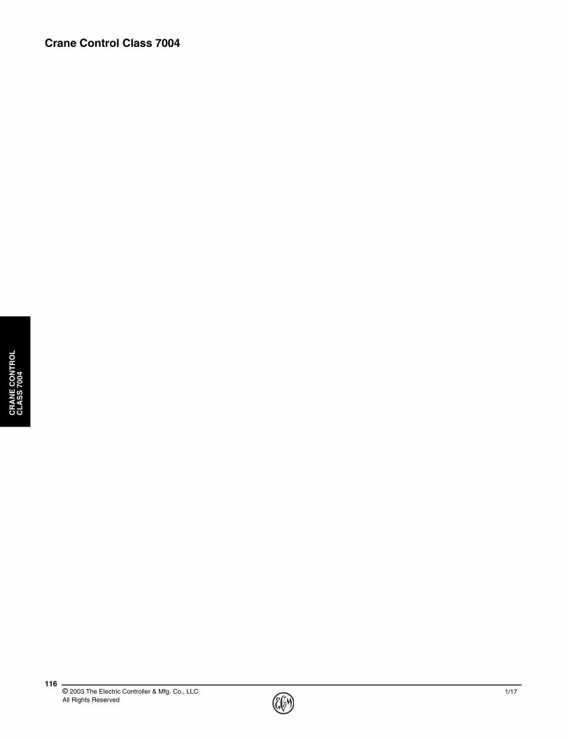
APPROXIMATE DIMENSIONS AND WEIGHTS
The table lists recommended minimum enclosure sizes for single pole-240 VDC contactors with contactor mounted accessories. For double pole contactors, increase width by 50%.
▲ Electrical interlocks and all live electrical parts must have a clearance to ground and other live electrical parts.
✝ Not a NEMA size/rating.
NEMASize Type Fig.
No.
Contactor Dimensions ▲
Weight
Center to Center Spacing of S.P. Tied
or Mechanically Interlocked Contactors
A B C1 C2 D E F G H K L
12
MXCO1MXDO1
1 1.7946
8.65220
6.00153
6.38162
7.56192
0.5213
0.256
...2.2958
0.4411
...73
5.63143
12
MXCO3MXDO3
1 1.7946
8.65220
6.00153
6.38162
7.56192
0.5213
0.256
...2.2958
0.4411
...73
5.63143
34
MEO1MFO1
2 2.1254
13.10333
7.83199
7.40188
11.50292
0.5614
0.37510
5/16-18
2.1355
0.8020
...157
6.00153
34
MEO3MFO3
2 2.1254
13.10333
7.83199
7.40188
11.50292
0.5614
0.37510
5/16-18
2.1355
0.8020
...157
6.00153
55A✝
MGO1MGAO1
2 2.7570
16.54420
9.50242
9.68246
14.50368
0.9625
0.37510
3/8-162.7871
1.0226
...3014
7.00178
55A✝
MGO3MGAO3
2 2.7570
16.54420
9.50242
9.68246
14.50368
0.9625
0.37510
3/8-162.7871
1.0226
...3014
7.00178
66A ✝
MHO1MHAO1
3 3.5089
19.15487
...13.64346
6.00153
...0.375
101/2-13
2.8573
8.30211
2.9475
7032
9.00229
6 MHO3 3 3.5089
19.15487
...13.64346
6.00153
...0.375
101/2-13
2.8573
8.30211
2.9475
7032
9.00229
8 MKO1 3 4.50114
22.90582
17.40442
15.80402
12.00305
2.3059
0.5013
1/2-136.90176
5.38137
3.6994
16073
11.30287
8 MKO3 3 4.50114
22.90582
17.40442
15.80402
12.00305
2.3059
0.5013
1/2-136.90176
5.38137
3.6994
16073
11.30287
NEMASize
TypeFig.No.
Accessory Dimensions▲ Arcing Clearances
Electrical Interlock 240 VDC 600 VDC
Q S X Y Z X Y Z12
MXCO1MXDO1
1 9.98253
2.3460
1.7043
1.7043
...3.0076
3.0076
...
12
MXCO3MXDO3
1 9.98253
2.3460
1.7043
1.7043
...3.0076
3.0076
...
34
MEO1MFO1
2 13.74349
2.4362
2.0051
2.0051
4.00102
2.0051
6.00153
4.00102
34
MEO3MFO3
2 13.74349
2.4362
2.0051
2.0051
4.00102
2.0051
6.00153
4.00102
55
MGO1MGO3
2 16.72424
2.6066
2.0452
2.8071
...2.0452
6.00153
...
5A✝5A✝
MGAO1MGAO3
2 16.72424
2.6066
2.5064
3.282
...2.5064
6.00153
...
6 MHO1 3 18.54471
2.4362
2.051
2.6066
3.5089
4.00102
11.00280
3.5089
6A✝MHAO1 3 18.54
4712.4362
4.0102
6.0153
3.5089
7.00178
12.00305
3.5089
6 MHO3 3 18.54471
2.4362
2.051
2.6066
...4.00102
11.00280
...
88
MKO1MKO3
3 23.5597
3.4588
4.5115
4.5115
4.00102
9.00229
12.00305
4.00102
NEMA Size Height Width Depth12
12.00305
12.00305
9.00229
34
18.00457
12.00305
12.00305
5 22.00559
15.00381
15.00381
5A✝ 28.00714
17.00434
18.00457
6 32.00813
18.00457
20.00508
6A✝ 40.001020
22.00561
24.00610
8 48.001219
24.00610
24.00610
Dual Dimensions: inmm
Dual Weights: lbkg
13.50
Crane Control Class 7004
CR
AN
E C
ON
TR
OL
C
LA
SS
700
4
© 2003 The Electric Controller & Mfg. Co., LLC All Rights Reserved
1161/17