Embed Size (px)
Citation preview

CRAM format specification (version 3.0)
26 Nov 2019
The master version of this document can be found at https://github.com/samtools/hts-specs.This printing is version 5a5d05f from that repository, last modified on the date shown above.
license: Apache 2.0
1 Overview
This specification describes the CRAM 3.0 format.
CRAM has the following major objectives:
1. Significantly better lossless compression than BAM
2. Full compatibility with BAM
3. Effortless transition to CRAM from using BAM files
4. Support for controlled loss of BAM data
The first three objectives allow users to take immediate advantage of the CRAM format while offering a smoothtransition path from using BAM files. The fourth objective supports the exploration of different lossy compres-sion strategies and provides a framework in which to effect these choices. Please note that the CRAM formatdoes not impose any rules about what data should or should not be preserved. Instead, CRAM supports a widerange of lossless and lossy data preservation strategies enabling users to choose which data should be preserved.
Data in CRAM is stored either as CRAM records or using one of the general purpose compressors (gzip, bzip2).CRAM records are compressed using a number of different encoding strategies. For example, bases are referencecompressed by encoding base differences rather than storing the bases themselves.1
2 Data types
CRAM specification uses logical data types and storage data types; logical data types are written as words (e.g.int) while physical data types are written using single letters (e.g. i). The difference between the two is thatstorage data types define how logical data types are stored in CRAM. Data in CRAM is stored either as bitsor bytes. Writing values as bits and bytes is described in detail below.
2.1 Logical data types
ByteSigned byte (8 bits).
1Markus Hsi-Yang Fritz, Rasko Leinonen, Guy Cochrane, and Ewan Birney, Efficient storage of high throughputDNA sequencing data using reference-based compression, Genome Res. 2011 21: 734–740; doi:10.1101/gr.114819.110;pmid:21245279.
1
IntegerSigned 32-bit integer.
LongSigned 64-bit integer.
ArrayAn array of any logical data type: <type>[ ]
2.2 Writing bits to a bit stream
A bit stream consists of a sequence of 1s and 0s. The bits are written most significant bit first where new bitsare stacked to the right and full bytes on the left are written out. In a bit stream the last byte will be incompleteif less than 8 bits have been written to it. In this case the bits in the last byte are shifted to the left.
Example of writing to bit stream
Let’s consider the following example. The table below shows a sequence of write operations:
Operation order Buffer state before Written bits Buffer state after Issued bytes1 0x0 1 0x1 -2 0x1 0 0x2 -3 0x2 11 0xB -4 0xB 0000 0111 0x7 0xB0
After flushing the above bit stream the following bytes are written: 0xB0 0x70. Please note that the last bytewas 0x7 before shifting to the left and became 0x70 after that:
> echo "obase=16; ibase=2; 00000111" | bc7
> echo "obase=16; ibase=2; 01110000" | bc70
And the whole bit sequence:
> echo "obase=2; ibase=16; B070" | bc1011000001110000
When reading the bits from the bit sequence it must be known that only 12 bits are meaningful and the bitstream should not be read after that.
Note on writing to bit stream
When writing to a bit stream both the value and the number of bits in the value must be known. This is becauseprogramming languages normally operate with bytes (8 bits) and to specify which bits are to be written requiresa bit-holder, for example an integer, and the number of bits in it. Equally, when reading a value from a bitstream the number of bits must be known in advance. In case of prefix codes (e.g. Huffman) all possible bitcombinations are either known in advance or it is possible to calculate how many bits will follow based on thefirst few bits. Alternatively, two codes can be combined, where the first contains the number of bits to read.
2.3 Writing bytes to a byte stream
The interpretation of byte stream is straightforward. CRAM uses little endianness for bytes when applicableand defines the following storage data types:
Boolean (bool)Boolean is written as 1-byte with 0x0 being ‘false’ and 0x1 being ‘true’.
Integer (int32)Signed 32-bit integer, written as 4 bytes in little-endian byte order.
2

Long (int64)Signed 64-bit integer, written as 8 bytes in little-endian byte order.
ITF-8 integer (itf8)This is an alternative way to write an integer value. The idea is similar to UTF-8 encoding and thereforethis encoding is called ITF-8 (Integer Transformation Format - 8 bit).
The most significant bits of the first byte have special meaning and are called ‘prefix’. These are 0 to 4true bits followed by a 0. The number of 1’s denote the number of bytes to follow. To accommodate 32bits such representation requires 5 bytes with only 4 lower bits used in the last byte 5.
LTF-8 long (ltf8)See ITF-8 for more details. The only difference between ITF-8 and LTF-8 is the number of bytes used toencode a single value. To do so 64 bits are required and this can be done with 9 byte at most with thefirst byte consisting of just 1s or 0xFF value.
Array ([ ])Array length is written first as integer (itf8), followed by the elements of the array.
EncodingEncoding is a data type that specifies how data series have been compressed. Encodings are defined asencoding<type> where the type is a logical data type as opposed to a storage data type.
An encoding is written as follows. The first integer (itf8) denotes the codec id and the second integer(itf8) the number of bytes in the following encoding-specific values.
Subexponential encoding example:Value Type Name0x7 itf8 codec id0x2 itf8 number of bytes to follow0x0 itf8 offset0x1 itf8 K parameter
The first byte “0x7” is the codec id.
The next byte “0x2” denotes the length of the bytes to follow (2).
The subexponential encoding has 2 parameters: integer (itf8) offset and integer (itf8) K.
offset = 0x0 = 0
K = 0x1 = 1
MapA map is a collection of keys and associated values. A map with N keys is written as follows:
size in bytes N key 1 value 1 key ... value ... key N value N
Both the size in bytes and the number of keys are written as integer (itf8). Keys and values are writtenaccording to their data types and are specific to each map.
StringA string is represented as byte arrays using UTF-8 format. Read names, reference sequence names andtag values with type ‘Z’ are stored as UTF-8.
3 Encodings
Encoding is a data structure that captures information about compression details of a data series that arerequired to uncompress it. This could be a set of constants required to initialize a specific decompressionalgorithm or statistical properties of a data series or, in case of data series being stored in an external block,the block content id.
Encoding notation is defined as the keyword ‘encoding’ followed by its data type in angular brackets, for example‘encoding<byte>’ stands for an encoding that operates on a data series of data type ‘byte’.
Encodings may have parameters of different data types, for example the EXTERNAL encoding has only oneparameter, integer id of the external block. The following encodings are defined:
3

Codec ID Parameters CommentNULL 0 none series not preservedEXTERNAL 1 int block content id the block content identifier used to
associate external data blocks withdata series
Deprecated (GOLOMB) 2 int offset, int M Golomb codingHUFFMAN 3 int array, int array coding with int/byte valuesBYTE_ARRAY_LEN 4 encoding<int> array length,
encoding<byte> bytescoding of byte arrays with arraylength
BYTE_ARRAY_STOP 5 byte stop, int external blockcontent id
coding of byte arrays with a stopvalue
BETA 6 int offset, int number of bits binary codingSUBEXP 7 int offset, int K subexponential codingDeprecated (GOLOMB_RICE) 8 int offset, int log2m Golomb-Rice codingGAMMA 9 int offset Elias gamma coding
See section 13 for more detailed descriptions of all the above coding algorithms and their parameters.
4 Checksums
The checksumming is used to ensure data integrity. The following checksumming algorithms are used in CRAM.
4.1 CRC32
This is a cyclic redundancy checksum 32-bit long with the polynomial 0x04C11DB7. Please refer to ITU-TV.42 for more details. The value of the CRC32 hash function is written as an integer.
4.2 CRC32 sum
CRC32 sum is a combination of CRC32 values by summing up all individual CRC32 values modulo 232.
5 File structure
The overall CRAM file structure is described in this section. Please refer to other sections of this document formore detailed information.
A CRAM file consists of a fixed length file definition, followed by a CRAM header container, then one or moredata containers, and finally a special end-of-file container.
Filedefinition
CRAM HeaderContainer
DataContainer
... DataContainer
CRAM EOFContainer
Figure 1: A CRAM file consists of a file definition, followed by a header container, then other containers.
Containers consist of one or more blocks. The first container, called the CRAM header container, is used tostore a textual header as described in the SAM specification (see the section 7.1).
Filedefinition
CRAM HeaderContainer
DataContainer
... DataContainer
CRAM EOFContainer
Block 1:CRAM Header
(optionally compressed)
Optional Block 2:nul padding bytes(uncompressed)
4

Figure 2: The the first container holds the CRAM header text.
Each container starts with a container header structure followed by one or more blocks. The first block in eachcontainer is the compression header block giving details of how to decode data in subsequent blocks. Each blockstarts with a block header structure followed by the block data.
Filedefinition
CRAM HeaderContainer
DataContainer
... DataContainer
CRAM EOFContainer
ContainerHeader structure
CompressionHeader Block Block 1 ... Block M
Block Headerstructure Block data
Figure 3: Containers as a series of blocks
The blocks after the compression header are organised logically into slices. One slice may contain, for example,a contiguous region of alignment data. Slices begin with a slice header block and are followed by one or moredata blocks. It is these data blocks which hold the primary bulk of CRAM data. The data blocks are furthersubdivided into a core data block and one or more external data blocks.
Filedefinition
CRAM HeaderContainer
DataContainer
... DataContainer
CRAM EOFContainer
ContainerHeader structure
CompressionHeader Block Block ... Block . . . Block ... Block
Slice 1 Slice N
Slice HeaderBlock
Core DataBlock
ExternalData Block 1
... ExternalData Block M
Figure 4: Slices formed from a series of concatenated blocks
6 File definition
Each CRAM file starts with a fixed length (26 bytes) definition with the following fields:
Data type Name Valuebyte[4] format magic number CRAM (0x43 0x52 0x41 0x4d)unsigned byte major format number 3 (0x3)unsigned byte minor format number 0 (0x0)byte[20] file id CRAM file identifier (e.g. file name or SHA1 checksum)
Valid CRAM major.minor version numbers are as follows:
1.0 The original public CRAM release.
2.0 The first CRAM release implemented in both Java and C; tidied up implementation vs specificationdifferences in 1.0.
2.1 Gained end of file markers; compatible with 2.0.
3.0 Additional compression methods; header and data checksums; improvements for unsorted data.
5

7 Container header structure
The file definition is followed by one or more containers with the following header structure where the containercontent is stored in the ‘blocks’ field:Data type Name Valueint32 length the sum of the lengths of all blocks in this container
(headers and data); equal to the total byte length of thecontainer minus the byte length of this header structure
itf8 reference sequence id reference sequence identifier or-1 for unmapped reads-2 for multiple reference sequences.All slices in this container must have a reference sequenceid matching this value.
itf8 starting position on thereference
the alignment start position or0 if the container is multiple-reference or containsunmapped unplaced reads
itf8 alignment span the length of the alignment or0 if the container is multiple-reference or containsunmapped unplaced reads
itf8 number of records number of records in the containerltf8 record counter 1-based sequential index of records in the file/stream.ltf8 bases number of read basesitf8 number of blocks the total number of blocks in this containeritf8[ ] landmarks the locations of slices in this container as byte offsets from
the end of this container header, used for random accessindexing. The landmark count must equal the slice count.Since the block before the first slice is the compressionheader, landmarks[0] is equal to the byte length of thecompression header.
int crc32 CRC32 hash of the all the preceding bytes in the container.byte[ ] blocks The blocks contained within the container.
7.1 CRAM header container
The first container in a CRAM file contains a textual header in a single block, optionally gzip compressed. Thistext header currently matches the SAM header specification. Only gzip is allowed as compression method forthis block. The CRAM header container does not include a compression header block.
It is recommended to reserve 50% more space in the CRAM header container than is required for the SAMheader text by optionally padding the container with a second raw block consisting of all zeroes. This canbe used to subsequently expand the header container in place, such as when updating @SQ records, whilepreserving the absolute offsets of all subsequent containers.
8 Block structure
Containers consist of one or more blocks. Block compression is applied independently and in addition to anyencodings used to compress data within the block. The block have the following header structure with the datastored in the ‘block data’ field:
6

Data type Name Valuebyte method the block compression method:
0: raw (none)*1: gzip2: bzip23: lzma4: rans
byte block content type id the block content type identifieritf8 block content id the block content identifier used to associate external data
blocks with data seriesitf8 size in bytes* size of the block data after applying block compressionitf8 raw size in bytes* size of the block data before applying block compressionbyte[ ] block data the data stored in the block:
• bit stream of CRAM records (core data block)• byte stream (external data block)• additional fields ( header blocks)
byte[4] CRC32 CRC32 hash value for all preceding bytes in the block
* Note on raw method: both compressed and raw sizes must be set to the same value.
8.1 Block content types
CRAM has the following block content types:
Block content type Blockcontenttype id
Name Contents
FILE_HEADER 0 CRAM header block CRAM headerCOMPRESSION_HEADER 1 Compression header block See specific sectionSLICE_HEADERa 2 Slice header block See specific section
3 reservedEXTERNAL_DATA 4 external data block data produced by
external encodingsCORE_DATA 5 core data block bit stream of all
encodings except forexternal encodings
a Formerly MAPPED_SLICE_HEADER. Now used by all slice headers regardless of mapping status.
8.2 Block content id
Block content id is used to distinguish between external blocks in the same slice. Each external encoding hasan id parameter which must be one of the external block content ids. For external blocks the content id is apositive integer. For all other blocks content id should be 0. Consequently, all external encodings must not usecontent id less than 1.
Data blocks
Data is stored in data blocks. There are two types of data blocks: core data blocks and external data blocks.Thedifference between core and external data blocks is that core data blocks consist of data series that are compressedusing bit encodings while the external data blocks are byte compressed. One core data block and any numberof external data blocks are associated with each slice.
Writing to and reading from core and external data blocks is organised through CRAM records. Each dataseries is associated with an encoding. In case of external encodings the block content id is used to identify theblock where the data series is stored. Please note that external blocks can have multiple data series associatedwith them; in this case the values from these data series will be interleaved.
7

8.3 CRAM header block
The SAM header is stored in a single block within the first container.
The following constraints apply to the SAM header:
• The SQ:MD5 checksum is required unless the reference sequence has been embedded into the file.
8.4 Compression header block
The compression header block consists of 3 parts: preservation map, data series encoding map and tag encodingmap.
Preservation map
The preservation map contains information about which data was preserved in the CRAM file. It is stored asa map with byte[2] keys:
Key Value data type Name ValueRN bool read names included true if read names are preserved for all readsAP bool AP data series delta true if AP data series is delta, false otherwiseRR bool reference required true if reference sequence is required to restore
the data completelySM byte[5] substitution matrix substitution matrixTD byte[ ] tag ids dictionary a list of lists of tag ids, see tag encoding section
The boolean values are optional, defaulting to true when absent, although it is recommended to explicitly setthem. SM and TD are mandatory.
Data series encodings
Each data series has an encoding. These encoding are stored in a map with byte[2] keys and are decoded inapproximately this order2:
2The precise order is defined in section 10.
8

Key Value data type Name ValueBF encoding<int> BAM bit flags see separate sectionCF encoding<int> CRAM bit flags see specific sectionRI encoding<int> reference id record reference id from the SAM file headerRL encoding<int> read lengths read lengthsAP encoding<int> in-seq positions if AP-Delta = true: 0-based alignment start
delta from the AP value in the previous record.Note this delta may be negative, for examplewhen switching references in a multi-referenceslice. When the record is the first in the slice, theprevious position used is the slice alignment-startfield (hence the first delta should be zero forsingle-reference slices, or the AP value itself formulti-reference slices).if AP-Delta = false: encodes the alignment startposition directly
RG encoding<int> read groups read groups. Special value ‘-1’ stands for nogroup.
RNa encoding<byte[ ]> read names read namesMF encoding<int> next mate bit flags see specific sectionNS encoding<int> next fragment
reference sequence idreference sequence ids for the next fragment
NP encoding<int> next mate alignmentstart
alignment positions for the next fragment
TS encoding<int> template size template sizesNF encoding<int> distance to next
fragmentnumber of records to the next fragmentb
TLc encoding<int> tag ids list of tag ids, see tag encoding sectionFN encoding<int> number of read
featuresnumber of read features in each record
FC encoding<byte> read features codes see separate sectionFP encoding<int> in-read positions positions of the read featuresDL encoding<int> deletion lengths base-pair deletion lengthsBB encoding<byte[ ]> stretches of bases basesQQ encoding<byte[ ]> stretches of quality
scoresquality scores
BS encoding<byte> base substitutioncodes
base substitution codes
IN encoding<byte[ ]> insertion inserted basesRS encoding<int> reference skip length number of skipped bases for the ‘N’ read featurePD encoding<int> padding number of padded basesHC encoding<int> hard clip number of hard clipped basesSC encoding<byte[ ]> soft clip soft clipped basesMQ encoding<int> mapping qualities mapping quality scoresBA encoding<byte> bases basesQS encoding<byte> quality scores quality scoresa Note RN this is decoded after MF if the record is detached from the mate and we are attempting toauto-generate read names.
b The count is reset for each slice so NF can only refer to a record later within this slice.c TL is followed by decoding the tag values themselves, in order of appearance in the tag dictionary.
Tag encodings
The tag dictionary (TD) describes the unique combinations of tag id / type that occur on each alignment record.For example if we search the id / types present in each record and find only two combinations – X1:i BC:ZSA:Z: and X1:i: BC:Z – then we have two dictionary entries in the TD map.
9

Let Li = {Ti0, Ti1, . . . , Tix} be a list of all tag ids for a record Ri, where i is the sequential record index andTij denotes j-th tag id in the record. The list of unique Li is stored as the TD value in the preservation map.Maintaining the order is not a requirement for encoders (hence “combinations”), but it is permissible and thusdifferent permutations, each encoded with their own elements in TD, should be supported by the decoder. EachLi element in TD is assigned a sequential integer number starting with 0. These integer numbers are referredto by the TL data series. Using TD, an integer from the TL data series can be mapped back into a list of tagids. Thus per alignment record we only need to store tag values and not their ids and types.
The TD is written as a byte array consisting of Li values separated with \0. Each Li value is written as aconcatenation of 3 byte Tij elements: tag id followed by BAM tag type code (one of A, c, C, s, S, i, I, f, F, Z, Hor B, as described in the SAM specification). For example the TD for tag lists X1:i BC:Z SA:Z and X1:i BC:Zmay be encoded as X1CBCZSAZ\0X1CBCZ\0, with X1C indicating a 1 byte unsigned value for tag X1.
Tag values
The encodings used for different tags are stored in a map. The key is 3 bytes formed from the BAM tag idand type code, matching the TD dictionary described above. Unlike the Data Series Encoding Map, the key isstored in the map as an ITF8 encoded integer, constructed using (char1 << 16) + (char2 << 8) + type. Forexample, the 3-byte representation of OQ:Z is {0x4F, 0x51, 0x5A} and these bytes are intepreted as the integerkey 0x004F515A, leading to an ITF8 byte stream {0xE0, 0x4F, 0x51, 0x5A}.
Key Value data type Name ValueTAG ID 1:TAG TYPE 1 encoding<byte[ ]> read tag 1 tag values (names and types are
available in the data series code)... ... ...TAG ID N:TAG TYPE N encoding<byte[ ]> read tag N ...
Note that tag values are encoded as array of bytes. The routines to convert tag values into byte array and backare the same as in BAM with the exception of value type being captured in the tag key rather in the value.Hence consuming 1 byte for types ‘C’ and ‘c’, 2 bytes for types ‘S’ and ‘s’, 4 bytes for types ‘I’, ‘i’ and ‘f’, anda variable number of bytes for types ‘H’, ‘Z’ and ‘B’.
8.5 Slice header block
The slice header block is never compressed (block method=raw). For reference mapped reads the slice headeralso defines the reference sequence context of the data blocks associated with the slice. Mapped reads can bestored along with placed unmapped3 reads on the same reference within the same slice.
Slices with the Multiple Reference flag (-2) set as the sequence ID in the header may contain reads mapped tomultiple external references, including unmapped3 reads (placed on these references or unplaced), but multipleembedded references cannot be combined in this way. When multiple references are used, the RI data serieswill be used to determine the reference sequence ID for each record. This data series is not present when onlya single reference is used within a slice.
The Unmapped (-1) sequence ID in the header is for slices containing only unplaced unmapped3 reads.
A slice containing data that does not use the external reference in any sequence may set the reference MD5sum to zero. This can happen because the data is unmapped or the sequence has been stored verbatim insteadof via reference-differencing. This latter scenario is recommended for unsorted or non-coordinate-sorted data.
The slice header block contains the following fields.3Unmapped reads can be placed or unplaced. By placed unmapped read we mean a read that is unmapped according to bit
0x4 of the BF (BAM bit flags) data series, but has position fields filled in, thus "placing" it on a reference sequence. In contrast,unplaced unmapped reads have have a reference sequence ID of -1 and alignment position of 0.
10

Data type Name Valueitf8 reference sequence id reference sequence identifier or
-1 for unmapped reads-2 for multiple reference sequences.This value must match that of its enclosingcontainer.
itf8 alignment start the alignment start position.0 if the slice is multiple-reference or containsunmapped unplaced reads
itf8 alignment span the length of the alignment.0 if the slice is multiple-reference or containsunmapped unplaced reads
itf8 number of records the number of records in the sliceltf8 record counter 1-based sequential index of records in the
file/streamitf8 number of blocks the number of blocks in the sliceitf8[ ] block content ids block content ids of the blocks in the sliceitf8 embedded reference bases block content id block content id for the embedded reference
sequence bases or -1 for nonebyte[16] reference md5 MD5 checksum of the reference bases within
the slice boundaries. If this slice hasreference sequence id of -1 (unmapped) or -2(multi-ref) the MD5 should be 16 bytes of \0.For embedded references, the MD5 can eitherbe all-zeros or the MD5 of the embeddedsequence.
byte[] optional tags a series of tag,type,value tuples encoded asper BAM auxiliary fields.
The optional tags are encoded in the same manner as BAM tags. I.e. a series of binary encoded tags concatenatedtogether where each tag consists of a 2 byte key (matching [A-Za-z][A-Za-z0-9]) followed by a 1 byte type([AfZHcCsSiIB]) followed by a string of bytes in a format defined by the type.
Tags starting in a capital letter are reserved while lowercase ones or those starting with X, Y or Z are userdefinable. Any tag not understood by a decoder should be skipped over without producing an error.
At present no tags are defined.
8.6 Core data block
A core data block is a bit stream (most significant bit first) consisting of data from one or more CRAM records.Please note that one byte could hold more then one CRAM record as a minimal CRAM record could be just afew bits long. The core data block has the following fields:
Data type Name Valuebit[ ] CRAM record 1 The first CRAM record... ... ...bit[ ] CRAM record N The Nth CRAM record
8.7 External data blocks
The relationship between the core data block and external data blocks is shown in the following picture:
11

CRAM Record
Bit Stream
Byte Streams
Bit Flags
Alignment Start
Read Length
Bases
Quality Scores
Tags...
Core Data Block
External
Data Block
External
Data Block
External
Data Block...
Bit encodings (Huffman, ...)
Byte encodings (external, ...)
Figure 5: The relationship between core and external encodings, and core and external data blocks.
The picture shows how a CRAM record (on the left) is distributed between the core data block and one or moreexternal data blocks, via core or external encodings. The specific encodings presented are only examples forpurposes of illustration. The main point is to distinguish between core bit encodings whose output is alwaysstored in a core data block, and external byte encodings whose output is always stored in external data blocks.
9 End of file container
A special container is used to mark the end of a file or stream. It is required in version 3 or later. The idea isto provide an easy and a quick way to detect that a CRAM file or stream is complete. The marker is basicallyan empty container with ref seq id set to -1 (unaligned) and alignment start set to 4542278.
Here is a complete content of the EOF container explained in detail:
12

hex bytes data type decimal value field nameContainer header0f 00 00 00 integer 15 size of blocks dataff ff ff ff 0f itf8 -1 ref seq ide0 45 4f 46 itf8 4542278 alignment start00 itf8 0 alignment span00 itf8 0 number of records00 itf8 0 global record counter00 itf8 0 bases01 itf8 1 block count00 array 0 landmarks05 bd d9 4f integer 1339669765 container header CRC32Compression header block00 byte 0 (RAW) compression method01 byte 1 (COMPRESSION_HEADER) block content type00 itf8 0 block content id06 itf8 6 compressed size06 itf8 6 uncompressed sizeCompression header01 itf8 1 preservation map byte size00 itf8 0 preservation map size01 itf8 1 encoding map byte size00 itf8 0 encoding map size01 itf8 1 tag encoding byte size00 itf8 0 tag encoding map sizeee 63 01 4b integer 1258382318 block CRC32
When compiled together the EOF marker is 38 bytes long and in hex representation is:
0f 00 00 00 ff ff ff ff 0f e0 45 4f 46 00 00 00 00 01 00 05 bd d9 4f 00 01 00 06 06 01 00 01 00 01 00 ee 63 01 4b
10 Record structure
CRAM record is based on the SAM record but has additional features allowing for more efficient data storage.In contrast to BAM record CRAM record uses bits as well as bytes for data storage. This way, for example,various coding techniques which output variable length binary codes can be used directly in CRAM. On theother hand, data series that do not require binary coding can be stored separately in external blocks with someother compression applied to them independently.
As CRAM data series may be interleaved within the same blocks4 understanding the order in which CRAMdata series must be decoded is vital.
The overall flowchart is below, with more detailed description in the subsequent sections.
10.1 CRAM record
Both mapped and unmapped reads start with the following fields. Please note that the data series type refersto the logical data type and the data series name corresponds to the data series encoding map.
4Interleaving can sometimes provide better compression, however it also adds dependency between types of data meaning it isnot possible to selectively decode one data series if it co-locates with another data series in the same block.
13

Data seriestype
Data seriesname
Field Description
int BF BAM bit flags see BAM bit flags belowint CF CRAM bit flags see CRAM bit flags below- - Positional data See section 10.2- - Read names See section 10.3- - Mate records See section 10.4- - Auxiliary tags See section 10.5- - Sequences See sections 10.6 and 10.7
BAM bit flags (BF data series)
The following flags are duplicated from the SAM and BAM specification, with identical meaning. Note howeversome of these flags can be derived during decode, so may be omitted in the CRAM file and the bits computedbased on both reads of a pair-end library residing within the same slice.
Bit flag Comment Description0x1 template having multiple
segments in sequencing0x2 each segment properly aligned
according to the aligner0x4 segment unmappeda
0x8 calculatedb or stored in themate’s info
next segment in templateunmapped
0x10 SEQ being reversecomplemented
0x20 calculatedb or stored in themate’s info
SEQ of the next segment in thetemplate being reversed
0x40 the first segment in the templatec
0x80 the last segment in the templatec
0x100 secondary alignment0x200 not passing quality controls0x400 PCT or optical duplicate0x800 Supplementary alignmenta Bit 0x4 is the only reliable place to tell whether the read is unmapped. If 0x4 is set, no assumptions maybe made about bits 0x2, 0x100 and 0x800.
b For segments within the same slice.c Bits 0x40 and 0x80 reflect the read ordering within each template inherent in the sequencing technologyused, which may be independent from the actual mapping orientation. If 0x40 and 0x80 are both set, theread is part of a linear template (one where the template sequence is expected to be in a linear order),but it is neither the first nor the last read. If both 0x40 and 0x80 are unset, the index of the read in thetemplate is unknown. This may happen for a non-linear template (such as one constructed by stitchingtogether other templates) or when this information is lost during data processing.
CRAM bit flags (CF data series)
The CRAM bit flags (also known as compression bit flags) expressed as an integer represent the CF data series.The following compression flags are defined for each CRAM read record:
14

Bit flag Name Description0x1 quality scores stored as array quality scores can be stored as read features or as an
array similar to read bases.0x2 detached mate information is stored verbatim (e.g. because the
pair spans multiple slices or the fields differ to theCRAM computed method)
0x4 has mate downstream tells if the next segment should be expected further inthe stream
0x8 decode sequence as “*” informs the decoder that the sequence is unknown andthat any encoded reference differences are present onlyto recreate the CIGAR string.
The following pseudocode describes the general process of decoding an entire CRAM record. The sequence dataitself is in one of two encoding formats depending on whether the record is aligned (mapped).
Decode pseudocode
1: procedure DecodeRecord2: BAM_flags ← ReadItem(BF, Integer)3: CRAM_flags ← ReadItem(CF, Integer)4: DecodePositions . See section 10.25: DecodeNames . See section 10.36: DecodeMateData . See section 10.47: DecodeTagData . See section 10.5
8: if (BF AND 4) 6= 0 then . Unmapped flag9: DecodeMappedRead . See section 10.6
10: else11: DecodeUnmappedRead . See section 10.712: end if13: end procedure
10.2 CRAM positional data
Following the bit-wise BAM and CRAM flags, CRAM encodes positional related data including reference,alignment positions and length, and read-group. Positional data is stored for both mapped and unmappedsequences, as unmapped data may still be “placed” at a specific location in the genome (without being aligned).Typically this is done to keep a sequence pair (paired-end or mate-pair sequencing libraries) together when oneof the pair aligns and the other does not.
For reads stored in a position-sorted slice, the AP-delta flag in the compression header preservation map shouldbe set and the AP data series will be delta encoded, using the slice alignment-start value as the first position todelta against. Note for multi-reference slices this may mean that the AP series includes negative values, such aswhen moving from an alignment to the end of one reference sequence to the start of the next or to unmappedunplaced data. When the AP-delta flag is not set the AP data series is stored as a normal integer value.
Data seriestype
Data seriesname
Field Description
int RI ref id reference sequence id (only present inmultiref slices)
int RL read length the length of the readint AP alignment start the alignment start positionint RG read group the read group identifier expressed as
the Nth record in the header, startingfrom 0 with -1 for no group
1: procedure DecodePositions2: if slice_header.reference_sequence_id = −2 then
15

3: reference_id← ReadItem(RI, Integer)4: else5: reference_id← slice_header.reference_sequence_id6: end if7: read_length← ReadItem(RL, Integer)8: if container_pmap.AP_delta 6= 0 then9: if first_record_in_slice then
10: last_position← slice_header.alignment_start11: end if12: alignment_position← ReadItem(AP, Integer) + last_position13: last_position← alignment_position14: else15: alignment_position← ReadItem(AP, Integer)16: end if17: read_group← ReadItem(RG, Integer)18: end procedure
10.3 Read names (RN data series)
Read names can be preserved in the CRAM format, but this is optional and is governed by the RN preservationmap key in the container compression header. See section 8.4. When read names are not preserved the CRAMdecoder should generate names, typically based on the file name and a numeric ID of the read using the recordcounter field of the slice header block. Note read names may still be preserved even when the RN compressionheader key indicates otherwise, such as where a read is part of a read-pair and the pair spans multiple slices. Inthis situation the record will be marked as detached (see the CF data series) and the mate data below (section10.4) will contain the read name.
Data seriestype
Data seriesname
Field Description
byte[] RN read names read names
1: procedure DecodeNames2: if container_pmap.read_names_included = 1 then3: read_name← ReadItem(RN, Byte[])4: else5: read_name← GenerateName6: end if
7: end procedure
10.4 Mate record
There are two ways in which mate information can be preserved in CRAM: number of records downstream(distance, within this slice) to the next fragment in the template and a special mate record if the next fragmentis not in the current slice. In the latter case the record is labelled as “detached”, see the CF data series.
For mates within the slice only the distance is captured, and only for the first record. The mate has neitherdetached nor downstream flags set in the CF data series.
Data seriestype
Data series name Description
int NF the number of records to the next fragment
In the above case, the NS (mate reference name), NP (mate position) and TS (template size) fields for bothrecords should be derived once the mate has also been decoded. Mate reference name and position are obviousand simply copied from the mate. The template size is computed using the method described in the SAMspecification; the inclusive distance from the leftmost to rightmost mapped bases with the sign being positivefor the leftmost record and negative for the rightmost record.
16

If the next fragment is not found within this slice then the following structure is included into the CRAM record.Note there are cases where read-pairs within the same slice may be marked as detached and use this structure,such as to store mate-pair information that does not match the algorithm used by CRAM for computing themate data on-the-fly.
Data seriestype
Data series name Description
int MF next mate bit flags, see table belowbyte[ ] RN the read name (if and only if not known already)int NS mate reference sequence identifierint NP mate alignment start positionint TS the size of the template (insert size)
Next mate bit flags (MF data series)
The next mate bit flags expressed as an integer represent the MF data series. These represent the missing bitswe excluded from the BF data series (when compared to the full SAM/BAM flags). The following bit flags aredefined:Bit flag Name Description0x1 mate negative strand bit the bit is set if the mate is on the negative strand0x2 mate mapped bit the bit is set if the mate is mapped
Decode mate pseudocode
In the following pseudocode we are assuming the current record is this and its mate is next_frag.1: procedure DecodeMateData2: if CF AND 2 then . Detached from mate3: mate_flags← ReadItem(MF,Integer)4: if mate_flags AND 1 then5: bam_flags← bam_flags OR 0x20 . Mate is reverse-complemented6: end if7: if mate_flags AND 2 then8: bam_flags← bam_flags OR 0x08 . Mate is unmapped9: end if
10: if container_pmap.read_names_included 6= 1 then11: read_name← ReadItem(RN, Byte[])12: end if13: mate_ref_id ← ReadItem(NS, Integer)14: mate_position ← ReadItem(NP, Integer)15: template_size ← ReadItem(TS, Integer)16: else if CF AND 4 then . Mate is downstream17: if next_frag.bam_flags AND 0x10 then18: this.bam_flags← this.bam_flags OR 0x20 . next segment reverse complemented19: end if20: if next_frag.bam_flags AND 0x04 then21: this.bam_flags← this.bam_flags OR 0x08 . next segment unmapped22: end if23: next_frag ← ReadItem(NF,Integer)24: Resolve mate_ref_id for this record and this+ next_frag once both have been decoded25: Resolve mate_position for this record and this+ next_frag once both have been decoded26: Find leftmost and rightmost mapped coordinate in records this and this+ next_frag.27: For leftmost of this and this+ next_frag record: template_size← rightmost− leftmost+ 128: For rightmost of this and this+ next_frag record: template_size← −(rightmost− leftmost+1)29: end if30: end procedure
Note as with the SAM specification a template may be permitted to have more than two alignment records.In this case the “mate” for each record is considered to be the next record, with the mate for the last record
17

being the first to form a circular list. The above algorithm is a simplification that does not deal with thisscenario. The full method needs to observe when record this + NF is also labelled as having an additionalmate downstream. One recommended approach is to resolve the mate information in a second pass, once theentire slice has been decoded. The final segment in the mate chain needs to set bam_flags fields 0x20 and0x08 accordingly based on the first segment. This is also not listed in the above algorithm, for brevity.
10.5 Auxiliary tags
Tags are encoded using a tag line (TL data series) integer into the tag dictionary (TD field in the compressionheader preservation map, see section 8.4). See section 8.4 for a more detailed description of this process.
Data seriestype
Data seriesname
Field Description
int TL tag line an index into the tag dictionary (TD)* ??? tag name/type 3 character key (2 tag identifier and 1 tag
type), as specified by the tag dictionary
1: procedure DecodeTagData2: tag_line← ReadItem(TL,Integer)3: for all ele ∈ container_pmap.tag_dict(tag_line) do4: name← first two characters of ele5: tag(type)← last character of ele6: tag(name)← ReadItem(ele, Byte[])7: end for8: end procedure
In the above procedure, name is a two letter tag name and type is one of the permitted types documentedin the SAM/BAM specification. Type is c (signed 8-bit integer), C (unsigned 8-bit integer), s (signed 16-bitinteger), S (unsigned 16-bit integer), i (signed 32-bit integer), I (unsigned 32-bit integer), f (32-bit float), Z(nul-terminated string), H (nul-terminated string of hex digits) and B (binary data in array format with thefirst byte being one of c,C,s,S,i,I,f using the meaning above, a 32-bit integer for the number of array elements,followed by array data encoded using the specified format). All integers are little endian encoded.
For example a SAM tag MQ:i has name MQ and type i and will be decoded using one of MQc, MQC, MQs,MQS, MQi and MQI data series depending on size and sign of the integer value.
10.6 Mapped reads
Read feature records
Read features are used to store read details that are expressed using read coordinates (e.g. base differencesrespective to the reference sequence). The read feature records start with the number of read features followedby the read features themselves. Finally the single mapping quality and per-base quality scores are stored.
Data series type Data seriesname
Field Description
int FN number of readfeatures
the number of read features
int FP in-read-positiona position of the read featurebyte FC read feature codea See feature codes below* * read feature dataa See feature codes belowint MQ mapping qualities mapping quality scorebyte[read length] QS quality scores the base qualities, if preserveda Repeated FN times, once for each read feature.
18

Read feature codes
Each feature code has its own associated data series containing further information specific to that feature. Thefollowing codes are used to distinguish variations in read coordinates:
Feature code Id Data seriestype
Data seriesname
Description
Bases b (0x62) byte[ ] BB a stretch of basesScores q (0x71) byte[ ] QQ a stretch of scoresRead base B (0x42) byte,byte BA,QS A base and associated quality
scoreSubstitution X (0x58) byte BS base substitution codes, SAM
operators X, M and =Insertion I (0x49) byte[ ] IN inserted bases, SAM operator
IDeletion D (0x44) int DL number of deleted bases,
SAM operator DInsert base i (0x69) byte BA single inserted base, SAM
operator IQuality score Q (0x51) byte QS single quality scoreReference skip N (0x4E) int RS number of skipped bases,
SAM operator NSoft clip S (0x53) byte[ ] SC soft clipped bases, SAM
operator SPadding P (0x50) int PD number of padded bases,
SAM operator PHard clip H (0x48) int HC number of hard clipped bases,
SAM operator H
Base substitution codes (BS data series)
A base substitution is defined as a change from one nucleotide base (reference base) to another (read base),including N as an unknown or missing base. There are 5 possible reference bases (ACGTN), with 4 possiblesubstitutions for each base, and 20 substitutions in total. The codes for all possible substitutions are stored ina substitution matrix. To restore a base, one would use the reference base and the substitution code, resolvingthe base via lookup in the substitution matrix.
Substitution Matrix Format
Each of the 4 possible substitutions for a given reference base is assigned a 2-bit integer code (see below) witha value ranging from 0 to 3 inclusive. The 4 2-bit codes are packed into a single byte, high 2-bits first, for eachbase ACGTN (minus the reference base itself). The entire substitution matrix is written as 5 such bytes, onefor each reference base, also in the order ACGTN.
Substitution Code Assignment
To assign the susbtitution code for a given reference base/read base, the substitutions for each reference basemay optionally be sorted by their frequencies, in descending order, with same-frequency ties broken using thefixed order ACGTN. Although sorting by substitution frequency is not required by the CRAM format, assigningsubstitution codes based on frequency maximizes compression by ensuring that the most frequent substitutionsuse the shortest possible codes.
For example, let us assume the following substitution frequencies for base A:
AC: 15%
AG: 25%
AT: 55%
19

AN: 5%
Then the substitution codes are:
AC: 2
AG: 1
AT: 0
AN: 3
The first byte of the substitution matrix entry for reference base A is written as a single byte, with the codes inthe order CGTN: 10 01 00 11 = 147 decimal, or 0x93 in this case. This will then be followed by 4 more bytesrepresenting substitutions for reference bases C, G, T and N.
Decode mapped read pseudocode
1: procedure DecodeMappedRead2: feature_number ← ReadItem(FN, Integer)3: for i← 1 to feature_number do4: DecodeFeature5: end for6: mapping_quality ← ReadItem(MQ, Integer)7: if container_pmap.preserve_quality_scores then8: for i← 1 to read_length do9: quality_score← ReadItem(QS, Integer)
10: end for11: end if12: end procedure
13: procedure DecodeFeature14: feature_code ← ReadItem(FC, Integer)15: feature_position← ReadItem(FP, Integer)16: if feature_code =‘B’ then17: base ← ReadItem(BA, Byte)18: quality_score ← ReadItem(QS, Byte)19: else if feature_code =‘X’ then20: substitution_code ← ReadItem(BS, Byte)21: else if feature_code =‘I’ then22: inserted_bases ← ReadItem(IN, Byte[])23: else if feature_code =‘S’ then24: softclip_bases ← ReadItem(SC, Byte[])25: else if feature_code =‘H’ then26: hardclip_length ← ReadItem(HC, Integer)27: else if feature_code =‘P’ then28: pad_length ← ReadItem(PD, Integer)29: else if feature_code =‘D’ then30: deletion_length ← ReadItem(DL, Integer)31: else if feature_code =‘N’ then32: ref_skip_length ← ReadItem(RS, Integer)33: else if feature_code =‘i’ then34: base ← ReadItem(BA, Byte)35: else if feature_code =‘b’ then36: bases ← ReadItem(BB, Byte[])37: else if feature_code =‘q’ then38: quality_scores ← ReadItem(QQ, Byte[])39: else if feature_code =‘Q’ then40: quality_score ← ReadItem(QS, Byte)41: end if42: end procedure
20

10.7 Unmapped reads
The CRAM record structure for unmapped reads has the following additional fields:
Data series type Data seriesname
Field Description
byte[read length] BA bases the read basesbyte[read length] QS quality scores the base qualities, if preserved
1: procedure DecodeUnmappedRead2: for i← 1 to read_length do3: base← ReadItem(BA, Byte)4: end for5: if container_pmap.preserve_quality_scores then6: for i← 1 to read_length do7: quality_score← ReadItem(QS, Byte)8: end for9: end if
10: end procedure
11 Reference sequences
CRAM format is natively based upon usage of reference sequences even though in some cases they are notrequired. In contrast to BAM format CRAM format has strict rules about reference sequences.
1. M5 (sequence MD5 checksum) field of @SQ sequence record in the BAM header is required and UR (URIfor the sequence fasta optionally gzipped file) field is strongly advised. The rule for calculating MD5 isto remove any non-base symbols (like \n, sequence name or length and spaces) and upper case the rest.Here are some examples:
> samtools faidx human_g1k_v37.fasta 1 | grep -v ’^>’ | tr -d ’\n’ | tr a-z A-Z | md5sum-1b22b98cdeb4a9304cb5d48026a85128 -
> samtools faidx human_g1k_v37.fasta 1:10-20 |grep -v ’^>’ |tr -d ’\n’ |tr a-z A-Z |md5sum-0f2a4865e3952676ffad2c3671f14057 -
Please note that the latter calculates the checksum for 11 bases from position 10 (inclusive) to 20 (inclusive)and the bases are counted 1-based, so the first base position is 1.
2. All CRAM reader implementations are expected to check for reference MD5 checksums and report anymissing or mismatching entries. Consequently, all writer implementations are expected to ensure that allchecksums are injected or checked during compression time.
3. In some cases reads may be mapped beyond the reference sequence. All out of range reference bases areall assumed to be ‘N’.
4. MD5 checksum bytes in slice header should be ignored for unmapped or multiref slices.
12 Indexing
General notes
Indexing is only valid on coordinate (reference ID and then leftmost position) sorted files.
Please note that CRAM indexing is external to the file format itself and may change independently of the fileformat specification in the future. For example, a new type of index file may appear.
21

Individual records are not indexed in CRAM files, slices should be used instead as a unit of random access.Another important difference between CRAM and BAM indexing is that CRAM container header and com-pression header block (first block in container) must always be read before decoding a slice. Therefore two readoperations are required for random access in CRAM.
Indexing a CRAM file is deemed to be a lightweight operation because it usually does not require any CRAMrecords to be read. Indexing information can be obtained from container headers, namely sequence id, alignmentstart and span, container start byte offset and slice byte offset inside the container (landmarks). The exceptionto this is with multi-reference containers, where the “RI” data series must be read.
CRAM index
A CRAM index is a gzipped tab delimited file containing the following columns:
1. Reference sequence id
2. Alignment start (ignored on read for unmapped slices, set to 0 on write)
3. Alignment span (ignored on read for unmapped slices, set to 0 on write)
4. Absolute byte offset of Container header in the file.
5. Relative byte offset of the Slice header block, from the end of the container header. This is the same asthe “landmark” field in the container header.
6. Slice size in bytes (including slice header and all blocks).
Each line represents a slice in the CRAM file. Please note that all slices must be listed in the index file.
Multi-reference slices may need to have multiple lines for the same slice; one for each reference contained withinthat slice. In this case the index reference sequence ID will be the actual reference ID (from the “RI” dataseries) and not -2.
Slices containing solely unmapped unplaced data (reference ID -1) still require values for all columns, althoughthe alignment start and span will be ignored. It is recommended that they are both set to zero.
To illustrate this the absolute and relative offsets used in a three slice container are shown in the diagram below.
ContainerHeader
CompressionHeader Block Slice 1 Slice 2 Slice 3
Containerabsoluteoffset
Slice offset 1
Slice offset 2
Slice offset 3
Size 1 Size 2 Size 3
BAM index
BAM indexes are supported by using 4-byte integer pointers called landmarks that are stored in containerheader. BAM index pointer is a 64-bit value with 48 bits reserved for the BAM block start position and 16 bitsreserved for the in-block offset. When used to index CRAM files, the first 48 bits are used to store the CRAMcontainer start position and the last 16 bits are used to store the index of the landmark in the landmark arraystored in container header. The landmark index can be used to access the appropriate slice.
The above indexing scheme treats CRAM slices as individual records in BAM file. This allows to apply BAMindexing to CRAM files, however it introduces some overhead in seeking specific alignment start because allpreceding records in the slice must be read and discarded.
22

13 Encodings
13.1 Introduction
The basic idea for codings is to efficiently represent some values in binary format. This can be achieved in anumber of ways that most frequently involve some knowledge about the nature of the values being encoded, forexample, distribution statistics. The methods for choosing the best encoding and determining its parametersare very diverse and are not part of the CRAM format specification, which only describes how the informationneeded to decode the values should be stored.
Note two of the encodings (Golomb and Golomb-Rice) are listed as deprecated. These are still formally partof the CRAM specification, but have not been used by the primary implementations and may not be wellsupported. Therefore their use is permitted, but not recommended.
Offset
Many of the codings listed below encode positive integer numbers. An integer offset value is used to allow anyinteger numbers and not just positive ones to be encoded. It can also be used for monotonically decreasingdistributions with the maximum not equal to zero. For example, given offset is 10 and the value to be encodedis 1, the actually encoded value would be offset+value=11. Then when decoding, the offset would be subtractedfrom the decoded value.
13.2 EXTERNAL: codec ID 1
Can encode types Byte, Integer.
The EXTERNAL coding is simply storage of data verbatim to an external block with a given ID. If the type isByte the data is stored as-is, otherwise for Integer type the data is stored in ITF8.
Parameters
CRAM format defines the following parameters of EXTERNAL coding:
Data type Name Commentitf8 external id id of an external block containing the byte stream
13.3 Huffman coding: codec ID 3
Can encode types Byte, Integer.
Huffman coding replaces symbols (values to encode) by binary codewords, with common symbols having shortercodewords such that the total message of binary codewords is shorter than using uniform binary codewordlengths. The general process consists of the following steps.
• Obtain symbol code lengths.
– If encoding:- Compute symbol frequencies.- Compute code lengths from frequencies.
– If decoding:- Read code lengths from codec parameters.
• Compute canonical Huffman codewords from code lengths5.
• Encode or decode bits as per the symbol to codeword table. Codewords have the “prefix property” thatno codeword is a prefix of another codeword, enabling unambiguous decode bit by bit.
5https://en.wikipedia.org/wiki/Canonical_Huffman_code
23

The use of canonical Huffman codes means that we only need to store the code lengths and use the samealgorithm in both encoder and decoder to generate the codewords. This is achieved by ensuring our symbolalphabet has a natural sort order and codewords are assigned in numerical order.
Important note: for alphabets with only one value, the codeword will be zero bits long. Thismakes the Huffman codec an efficient mechanism for specifying constant values.
Canonical code computation
1. Sort the alphabet ascending using bit-lengths and then using numerical order of the values.
2. The first symbol in the list gets assigned a codeword which is the same length as the symbol’s originalcodeword but all zeros. This will often be a single zero (’0’).
3. Each subsequent symbol is assigned the next binary number in sequence, ensuring that following codesare always higher in value.
4. When you reach a longer codeword, then after incrementing, append zeros until the length of the newcodeword is equal to the length of the old codeword.
Examples
Symbol Code length CodewordA 1 0B 3 100C 3 101D 3 110E 4 1110F 4 1111
Parameters
Data type Name Commentitf8[ ] alphabet list of all encoded symbols (values)itf8[ ] bit-lengths array of bit-lengths for each symbol in the alphabet
13.4 Byte array coding
Often there is a need to encode an array of bytes where the length is not predetermined. For example the readidentifiers differ per alignment record, possibly with different lengths, and this length must be stored somewhere.There are two choices available: storing the length explicitly (BYTE_ARRAY_LEN) or continuing to readbytes until a termination value is seen (BYTE_ARRAY_STOP).
Note in contrast to this, quality values are known to be the same length as the sequence which is an alreadyknown quantity, so this does not need to be encoded using the byte array codecs.
BYTE_ARRAY_LEN: codec ID 4
Can encode types Byte[].
Byte arrays are captured length-first, meaning that the length of every array element is written using anadditional encoding. For example this could be a HUFFMAN encoding or another EXTERNAL block. Thelength is decoded first followed by the data, followed by the next length and data, and so on.
This encoding can therefore be considered as a nested encoding, with each pair of nested encodings containingtheir own set of parameters. The byte stream for parameters of the BYTE_ARRAY_LEN encoding is thereforethe concatenation of the length and value encoding parameters as described in section 2.3.
The parameter for BYTE_ARRAY_LEN are listed below:
24

Data type Name Commentencoding<int> lengths encoding an encoding describing how the arrays lengths are
capturedencoding<byte> values encoding an encoding describing how the values are captured
For example, the bytes specifying a BYTE_ARRAY_LEN encoding, including the codec and parameters, fora 16-bit X0 auxiliary tag (“X0C”) may use HUFFMAN encoding to specify the length (always 2 bytes) and anEXTERNAL encoding to store the value to an external block with ID 200.
Bytes Meaning0x04 BYTE_ARRAY_LEN codec ID0x0a 10 remaining bytes of BYTE_ARRAY_LEN parameters
0x03 HUFFMAN codec ID, for aux tag lengths0x04 4 more bytes of HUFFMAN parameters0x01 Alphabet array size = 10x02 alphabet symbol; (length = 2)0x01 Codeword array size = 10x00 Code length = 0 (zero bits needed as alphabet is size 1)
0x01 EXTERNAL codec ID, for aux tag values0x02 2 more bytes of EXTERNAL parameters0x80 0xc8 ITF8 encoding for block ID 200
BYTE_ARRAY_STOP: codec ID 5
Can encode types Byte[].
Byte arrays are captured as a sequence of bytes terminated by a special stop byte. The data returned does notinclude the stop byte itself. In contrast to BYTE_ARRAY_LEN the value is always encoded with EXTERNALso the parameter is an external id instead of another encoding.
Data type Name Commentbyte stop byte a special byte treated as a delimiteritf8 external id id of an external block containing the byte stream
13.5 Beta coding: codec ID 6
Can encode types Integer.
Definition
Beta coding is a most common way to represent numbers in binary notation and is sometimes referred to asbinary coding. The decoder reads the specified fixed number of bits (most significant first) and subtracts theoffset value to get the decoded integer.
Parameters
CRAM format defines the following parameters of beta coding:
Data type Name Commentitf8 offset offset is subtracted from each
value during decodeitf8 length the number of bits used
Examples
If we have integer values in the range 10 to 15 inclusive, the largest value would traditionally need 4 bits, butwith an offset of -10 we can hold values 0 to 5, using a fixed size of 3 bits. Using fixed Offset and Length coming
25

from the beta parameters, we decode these values as:
Offset Length Bits Value-10 3 000 10-10 3 001 11-10 3 010 12-10 3 011 13-10 3 100 14-10 3 101 15
13.6 Subexponential coding: codec ID 7
Can encode types Integer.
Definition
Subexponential coding6 is parametrized by a non-negative integer k. For values n < 2k+1 subexponential codingproduces codewords identical to Rice coding 7. For larger values it grows logarithmically with n.
Encoding
1. Add offset to n.
2. Determine u and b values from n
b =
{k if n < 2k
blog2nc if n ≥ 2ku =
{0 if n < 2k
b− k + 1 if n ≥ 2k
3. Write u in unary form; u 1 bits followed by a single 0 bit.
4. Write the bottom b-bits of n in binary form.
Decoding
1. Read u in unary form, counting the number of leading 1s (prefix) in the codeword (discard the trailing 0bit).
2. Determine n via:
(a) if u = 0 then read n as a k-bit binary number.
(b) if u ≥ 1 then read x as a (u+ k − 1)-bit binary. Let n = 2u+k−1 + x.
3. Subtract offset from n.6Fast progressive lossless image compression, Paul G. Howard and Jeffrey Scott Vitter, 1994. http://www.ittc.ku.edu/~jsv/
Papers/HoV94.progressive_FELICS.pdf7https://en.wikipedia.org/wiki/Golomb_coding#Rice_coding
26

Examples
Number Codeword, k=0 Codeword, k=1 Codeword, k=20 0 00 0001 10 01 0012 1100 100 0103 1101 101 0114 111000 11000 10005 111001 11001 10016 111010 11010 10107 111011 11011 10118 11110000 1110000 1100009 11110001 1110001 11000110 11110010 1110010 110010
Parameters
Data type Name Commentitf8 offset offset is subtracted from each value during decodeitf8 k the order of the subexponential coding
13.7 Gamma coding: codec ID 9
Can encode types Integer.
Definition
Elias gamma code is a prefix encoding of positive integers. This is a combination of unary coding and betacoding. The first is used to capture the number of bits required for beta coding to capture the value.
Encoding
1. Write it in binary.
2. Subtract 1 from the number of bits written in step 1 and prepend that many zeros.
3. An equivalent way to express the same process:
4. Separate the integer into the highest power of 2 it contains (2N) and the remaining N binary digits ofthe integer.
5. Encode N in unary; that is, as N zeroes followed by a one.
6. Append the remaining N binary digits to this representation of N .
Decoding
1. Read and count 0s from the stream until you reach the first 1. Call this count of zeroes N .
2. Considering the one that was reached to be the first digit of the integer, with a value of 2N , read theremaining N digits of the integer.
27
Examples
Value Codeword1 12 0103 0114 00100
Parameters
Data type Name Commentitf8 offset offset to subtract from each
value after decode
13.8 DEPRECATED: Golomb coding: codec ID 2
Can encode types Integer.
Note this codec has not been used in any known CRAM implementation since before CRAM v1.0. Nor is itimplemented in some of the major software. Therefore its use is not recommended.
Definition
Golomb encoding is a prefix encoding optimal for representation of random positive numbers following geometricdistribution.
Encoding
1. Fix the parameter M to an integer value.
2. For N , the number to be encoded, find
(a) quotient q = bN/Mc(b) remainder r = N mod M
3. Generate Codeword
(a) The Code format : <Quotient Code><Remainder Code>, where(b) Quotient Code (in unary coding)
i. Write a q-length string of 1 bitsii. Write a 0 bit
(c) Remainder Code (in truncated binary encoding)Set b = dlog2(M)ei. If r < 2b −M code r as plain binary using b− 1 bits.ii. If r ≥ 2b −M code the number r + 2b −M in plain binary representation using b bits.
Decoding
1. Read q via unary coding: count the number of 1 bits and consume the following 0 bits.
2. Set b = dlog2(M)e
3. Read r via b− 1 bits of binary coding
4. If r ≥ 2b −M
(a) Read 1 single bit, x.(b) Set r = r ∗ 2 + x− (2b −M)
5. Value is q ∗M + r − offset
28

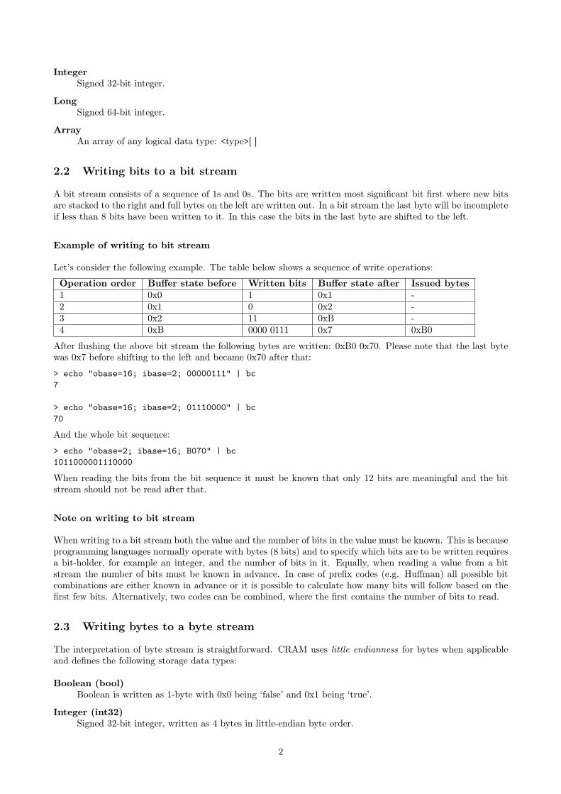
Examples
Number Codeword, M=10,(thus b=4)
0 00004 010010 1000026 110110042 11110010
Parameters
Golomb coding takes the following parameters:
Data type Name Commentitf8 offset offset is added to each valueitf8 M the golomb parameter (number
of bins)
13.9 DEPRECATED: Golomb-Rice coding: codec ID 8
Can encode types Integer.
Note this codec has not been used in any known CRAM implementation since before CRAM v1.0. Nor is itimplemented in some of the major software. Therefore its use is not recommended.
Golomb-Rice coding is a special case of Golomb coding when the M parameter is a power of 2. The reason forthis coding is that the division operations in Golomb coding can be replaced with bit shift operators as well asavoiding the extra r < 2b −M check.
14 External compression methods
External encoding operates on bytes only. Therefore any data series must be translated into bytes before sendingdata into an external block. The following agreements are defined.
Integer values are written as ITF8, which then can be translated into an array of bytes.
Strings, like read name, are translated into bytes according to UTF8 rules. In most cases these should coincidewith ASCII, making the translation trivial.
14.1 Gzip
The Gzip specification is defined in RFC 1952. Gzip in turn is an encapsulation on the Deflate algorithm definedin RFC 1951.
14.2 Bzip2
Bzip2 is a compression method utilising the Burrows Wheeler Transform, Move To Front transform, Run LengthEncoding and a Huffman entropy encoder. It is often superior to Gzip for textual data.
An informal format specification exists:https://github.com/dsnet/compress/blob/master/doc/bzip2-format.pdf
14.3 LZMA
LZMA is the Lempel-Ziv Markov chain algorithm. CRAM uses the xz Stream format to encapsulate thisalgorithm, as defined in https://tukaani.org/xz/xz-file-format.txt.
29

14.4 rANS codec
rANS is the range-coder variant of the Asymmetric Numerical System8.
The structure of the external rANS codec consists of several components: meta-data consisting of compression-order, and compressed and uncompressed sizes; normalised frequencies of the alphabet systems to be encoded,either in Order-0 or Order-1 context; and the rANS encoded byte stream itself.
Here "Order" refers to the number of bytes of context used in computing the frequencies. It will be 0 or 1.Ignoring punctuation and space, an Order-0 analysis of English text may observe that ‘e’ is the most commonletter (12-13%), and that ‘u’ occurs only around 2.5% of the time. If instead we consider the frequency of aletter in the context of one previous letter (Order-1) then these statistics change considerably; we know that ifthe previous letter was ‘q’ then ‘e’ becomes a rare letter while ‘u’ is the most likely.
These observed frequencies are directly related to the amount of storage required to encode a symbol (e.g. analphabet letter)9.
14.4.1 rANS compressed data structure
A compressed data block consists of the following logical parts:
Value data type Name Descriptionbyte order the order of the codec,
either 0 or 1int compressed size the size in bytes of
frequency table andcompressed blob
int data size raw or uncompresseddata size in bytes
byte[] frequency table byte frequencies ofinput data writtenusing RLE
byte[] compressed blob compressed data
14.4.2 Frequency table
The alphabet used here is simply byte values, so a maximum of 256 symbols as some values may not be present.
The symbol frequency table indicates which symbols are present and what their relative frequencies are. Thetotal sum of symbol frequencies are normalised to add up to 4095.
Formally, this is an ordered alphabet A containing symbols s where si with the i-th symbol in A, occurringwith the frequency freqi.
Order-0 encoding
The normalised symbol frequencies are then written out as {symbol, frequency} pairs in ascending order ofsymbol (0 to 255 inclusive). If a symbol has a frequency of 0 then it is omitted.
To avoid storing long consecutive runs of symbols if all are present (eg a-z in a long piece of English text)we use run-length-encoding on the alphabet symbols. If two consecutive symbols have non-zero frequenciesthen a counter of how many other non-zero frequency consecutive symbols is output directly after the secondconsecutive symbol, with that many symbols being subsequently omitted.
For example for non-zero frequency symbols ‘a’, ‘b’, ‘c’, ‘d’ and ‘e’ we would write out symbol ‘a’, ‘b’ and thevalue 3 (to indicate ‘c’, ‘d’ and ‘e’ are also present).
The frequency is output after every symbol (whether explicit or implicit) using ITF8 encoding. This meansthat frequencies 0-127 are encoded in 1 byte while frequencies 128-4095 are encoded in 2 bytes.
8J. Duda, Asymmetric numeral systems: entropy coding combining speed of Huffman coding with compression rate of arithmeticcoding, http://arxiv.org/abs/1311.2540
9C.E. Shannon, A Mathematical Theory of Communication, Bell System Technical Journal, vol. 27, pp. 379-423, 623-656, July,October, 1948
30

Finally the symbol 0 is written out to indicate the end of the symbol-frequency table.
As an example, take the string abracadabra.
Symbol frequency:
Symbol Frequencya 5b 2c 1d 1r 2
Normalised to sum to 4095:
Symbol Frequencya 1863b 744c 372d 372r 744
Encoded as:
0x61 0x87 0x47 # ‘a’ <1863>0x62 0x02 0x82 0xe8 # ‘b’ <+2: c,d> <744>
0x81 0x74 # ‘c’ (implicit) <372>0x81 0x74 # ‘d’ (implicit) <372>
0x72 0x82 0xe8 # ‘r’ <744>0x00 # <0>
Order-1 encoding
To encode Order-1 statistics typically requires a larger table as for an N sized alphabet we need to potentiallystore an NxN matrix. We store these as a series of Order-0 tables.
We start with the outer context byte, emitting the symbol if it is non-zero frequency. We perform the samerun-length-encoding as we use for the Order-0 table and end the contexts with a nul byte. After each contextbyte we emit the Order-0 table relating to that context.
One last caveat is that we have no context for the first byte in the data stream (in fact for 4 equally spacedstarting points, see “interleaving" below). We use the ASCII value (‘\0’) as the starting context and so need toconsider this in our frequency table.
Consider abracadabraabracadabraabracadabraabracadabra as example input.
Observed Order-1 frequencies:
Context Symbol Frequency\0 a 4a a 3
b 8c 4d 4
b r 8c a 4d a 4r a 8
Normalised (per Order-0 statistics):
Context Symbol Frequency\0 a 4095a a 646
b 1725c 862d 862
b r 4095c a 4095d a 4095r a 4095
Encoded as:
0x00 # ‘\0’ context0x61 0x8f 0xff # a <4095>0x00 # end of Order-0 table
0x61 # ‘a’ context0x61 0x82 0x86 # a <646>0x62 0x02 0x86 0xbd # b <+2: c,d> <1725>
0x83 0x5e # c (implicit) <862>0x83 0x5e # d (implicit) <862>
0x00 # end of Order-0 table
0x62 0x02 # ‘b’ context, <+2: c, d>
31

0x72 0x8f 0xff # r <4095>0x00 # end of Order-0 table
# ‘c’ context (implicit)0x61 0x8f 0xff # a <4095>0x00 # end of Order-0 table
# ‘d’ context (implicit)0x61 0x8f 0xff # a <4095>0x00 # end of Order-0 table
0x72 # ‘r’ context0x61 0x8f 0xff # a <4095>0x00 # end of Order-0 table
0x00 # end of contexts
14.4.3 rANS entropy encoding
The encoder takes a symbol s and a current state x (initially zero) to produce a new state x′ with function C.
x′ = C(s, x)
The decoding function D is the inverse of C such that C(D(x)) = x.
D(x′) = (s, x)
The entire encoded message can be viewed as a series of nested C operations, with decoding yielding the symbolsin reverse order, much like popping items off a stack. This is where the asymmetric part of ANS comes from.
As we encode into x the value will grow, so for efficiency we ensure that it always fits within known bounds.This is governed by
L ≤ x < bL− 1
where b is the base and L is the lower-bound.
We ensure this property is true before every use of C and after every use of D. Finally to end the stream weflush any remaining data out by storing the end state of x.
Implementation specifics
We use an unsigned 32-bit integer to hold x. In encoding it is initialised to zero. For decoding it is readlittle-endian from the input stream.
Recall freqi is the frequency of the i-th symbol si in alphabet A. We define cfreqi to be cumulative frequencyof all symbols up to but not including si:
cfreqi =
{0 if i < 1cfreqi−1 + freqi−1 if i ≥ 1
We have a reverse lookup table cfreq_to_symc from 0 to 4095 (0xfff) that maps a cumulative frequency c toa symbol s.
cfreq_to_symc = si where c : cfreqi ≤ c < cfreqi + freqi
The x′ = C(s, x) function used for the i− thsymbols is:
x′ = (x/freqi)× 0x1000+ cfreqi + (x mod freqi)
The D(x′) = (s, x) function used to produce the i-th symbol s and a new state x is:
c = x′&0xfffsi = cfreq_to_symc
x = freqi(x′/0x1000) + c− cfreqi
Most of these operations can be implemented as bit-shifts and bit-AND, with the encoder modulus beingimplemented as a multiplication by the reciprocal, computed once only per alphabet symbol.
32

We use L = 0x800000 and b = 256, permitting us to flush out one byte at a time (encoded and decoded inreverse order).
Before every encode C(s, x) we renormalise x, shifting out the bottom 8 bits of x until x < 0x80000 × freqi.After finishing encoding we flush 4 more bytes (lowest 8-bits first) from x.
After every decoded D(x′) we renormalise x′, shifting in the bottom 8 bits until x ≥ 0x800000.
Interleaving
For efficiency, we interleave 4 separate rANS codecs at the same time10. For the Order-0 codecs these simplyencode or decode the 4 neighbouring bytes in cyclic fashion using interleaved codec 1, 2, 3 and 4, sharing thesame output buffer (so the output bytes get interleaved).
For the Order-1 codec we cannot do this as we need to know the previous byte value as the context for thenext byte. Therefore split the input data into 4 approximately equal sized fragments11 starting at 0, blen/4c,blen/4c × 2 and blen/4c × 3. Each Order-1 codec operates in a cyclic fashion as with Order-0, all starting with0 as their state and sharing the same output buffer. Any remainder, when the input buffer is not divisible by4, is processed at the end by the 4th rANS state.
We do not permit Order-1 encoding of data streams smaller than 4 bytes.
10F. Giesen, Interleaved entropy coders, http://arxiv.org/abs/1402.339211This was why the ‘\0’ → ‘a’ context in the example above had a frequency of 4 instead of 1.
33
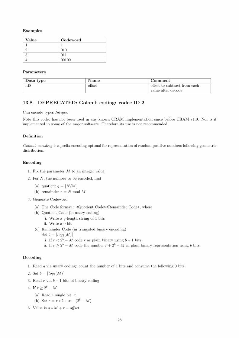
rANS decode pseudocode
A naïve implementation of a rANS decoder, follows. This pseudocode is for clarity only and is not expected tobe performant and we would normally rewrite this to use lookup tables for maximum efficiency. The functionReadByte below is undefined, but is expected to fetch the next single unsigned byte from an unspecified inputsource. Similarly for ReadITF8 (variable size inetger) and ReadUint32 (32-bit unsigned integer in littleendian format).
For brevity, we have also omitted error checking and array bounds checks.
The interpretation of some pseudocode syntax is listed below.
String Meaningx << y logical shift left of x by y bits.x >> y logical shift right of x by y bits.x & y bit-wise AND of x and y.Vi Element i of vector V .
The entire vector V may be passed into a function.Wi,j Element i, j of two-dimensional vector W .
The entire vector W or a one dimensional slice Wi (of size j) may be passed into a function.
1: procedure RansDecode(input, output)2: order ← ReadByte . Implicit read from input3: n_in ← ReadUint324: n_out← ReadUint325:6: if order = 0 then7: RansDecode0(output, n_out)8: else9: RansDecode1(output, n_out)
10: end if11: end procedure
rANS order-0
The Order-0 code is the simplest variant. Here we also define some of the functions for manipulating the rANSstate, which are shared between Order-0 and Order-1 decoders.
(Reads a table of Order-0 symbol frequencies Fi
(and sets the cumulative frequency table Ci+1 = Ci + Fi)1: procedure ReadFrequencies0(F,C)2: sym← ReadByte . Next alphabet symbol3: last_sym← sym4: rle← 05: repeat6: f ← ReadITF87: Fsym ← f8: if rle > 0 then9: rle ← rle− 1
10: sym ← sym+ 111: else12: sym← ReadByte13: if sym = last_sym+ 1 then14: rle← ReadByte15: end if16: end if17: last_sym← sym18: until sym = 0
(Compute cumulative frequencies Ci from Fi)
34

19: C0 ← 020: for i← 0 to 255 do21: Ci+1 ← Ci + Fi
22: end for23: end procedure
(Bottom 12 bits of our rANS state R are our frequency)24: function RansGetCumulativeFreq(R)25: return R & 0xfff26: end function
(Convert frequency to a symbol. Find s such that Cs ≤ f < Cs+1)(We would normally implement this via a lookup table)
27: function RansGetSymbolFromFreq(C, f)28: s← 029: while f >= Cs+1 do30: s← s+ 131: end while32: return s33: end function
(Compute the next rANS state R given frequency f and cumulative freq c)34: function RansAdvanceStep(R, c, f)35: return f × (R >> 12) + (R & 0xfff)− c36: end function
(If too small, feed in more bytes to the rANS state R)37: function RansRenorm(R)38: while R < (1 << 23) do39: R← (R << 8)+ ReadByte40: end while41: return R42: end function
43: procedure RansDecode0(output, nbytes)44: ReadFrequencies0(F, C) . Creates F and C vectors45: for j ← 0 to 3 do46: Rj ← ReadUint32 . Unsigned 32-bit little endian47: end for48: i← 049: while i < nbytes do50: for j ← 0 to 3 do51: if i+ j ≥ nbytes then return52: end if53: f ← RansGetCumulativeFreq(Rj)54: s← RansGetSymbolFromFreq(C, f)55: outputi+j ← s56: Rj ← RansAdvanceStep(Rj , Cs, Fs)57: Rj ← RansRenorm(Rj)58: end for59: i← i+ 460: end while61: end procedure
rANS order-1
As described above, the decode logic is very similar to rANS Order-0 except we have a two dimensional arrayof frequencies to read and the decode uses the last character as the context for decoding the next one. In the
35

pseudocode we demonstrate this by using two dimensional vectors Ci,j and Fi,j . For simplicity, we reuse theOrder-0 code by referring to Ci and Fi of the 2D vectors to get a single dimensional vector that operates in thesame manner as the Order-0 code. This is not necessarily the most efficient implementation.
Note the code for dealing with the remaining bytes when an output buffer is not an exact multiple of 4 is lesselegant in the Order-1 code. This is correct, but it is unfortunately a design oversight.
(Reads a table of Order-1 symbol frequencies Fi,j
(and sets the cumulative frequency table Ci,j+1 = Ci,j + Fi,j)1: procedure ReadFrequencies1(F,C)2: sym← ReadByte . Next alphabet symbol3: last_sym← sym4: rle← 05: repeat6: ReadFrequencies0(Fsym, Csym)7: if rle > 0 then8: rle ← rle− 19: sym← sym+ 1
10: else11: sym← ReadByte12: if sym = last_sym+ 1 then13: rle← ReadByte14: end if15: end if16: last_sym← sym17: until sym = 018: end procedure
19: procedure RansDecode1(output, nbytes)20: ReadFrequencies1(F, C) . Creates 2D F and C vectors21: for j ← 0 to 3 do22: Rj ← ReadUint32 . Unsigned 32-bit little endian23: Lj ← 024: end for25: i← 026: while i < bnbytes/4c do27: for j ← 0 to 3 do28: f ← RansGetCumulativeFreq(Rj)29: s← RansGetSymbolFromFreq(CLj , f)30: outputi+j×bnbytes/4c ← s31: Rj ← RansAdvanceStep(Rj , CLj ,s, FLj ,s)32: Rj ← RansRenorm(Rj)33: Lj ← s34: end for35: i← i+ 136: end while
(Now deal with the remainder if buffer size is not a multiple of 4,)(using rANS state 3 exclusively.)
37: i← 4× i38: while i < nbytes do39: f ← RansGetCumulativeFreq(R3)40: s← RansGetSymbolFromFreq(CL3
, f)41: outputi+3×bnbytes/4c ← s42: R3 ← RansAdvanceStep(R3, CL3,s, FL3,s)43: R3 ← RansRenorm(R3)44: L3 ← s45: i← i+ 146: end while47: end procedure
36

15 Appendix
15.1 Choosing the container size
CRAM format does not constrain the size of the containers. However, the following should be considered whendeciding the container size:
• Data can be compressed better by using larger containers
• Random access performance is better for smaller containers
• Streaming is more convenient for small containers
• Applications typically buffer containers into memory
We recommend 1 megabyte containers. They are small enough to provide good random access and streamingperformance while being large enough to provide good compression. 1MB containers are also small enough tofit into the L2 cache of most modern CPUs.
Some simplified examples are provided below to fit data into 1MB containers.
Unmapped short reads with bases, read names, recalibrated and original quality scores
We have 10,000 unmapped short reads (100bp) with read names, recalibrated and original quality scores. Weestimate 0.4 bits/base (read names) + 0.4 bits/base (bases) + 3 bits/base (recalibrated quality scores) + 3bits/base (original quality scores) ≈ 7 bits/base. Space estimate is 10 000× 100× 7 bits ≈ 0.9MB. Data couldbe stored in a single container.
Unmapped long reads with bases, read names and quality scores
We have 10,000 unmapped long reads (10kb) with read names and quality scores. We estimate: 0.4 bits/base(bases) + 3 bits/base (original quality scores) ≈ 3.5 bits/base. Space estimate is 10 000 × 10 000 × 3.5 bits ≈42MB. Data could be stored in 42× 1MB containers.
Mapped short reads with bases, pairing and mapping information
We have 250,000 mapped short reads (100bp) with bases, pairing and mapping information. We estimate thecompression to be 0.2 bits/base. Space estimate is 250 000× 100× 0.2 bits ≈ 0.6MB. Data could be stored ina single container.
Embedded reference sequences
We have a reference sequence (10Mb). We estimate the compression to be 2 bits/base. Space estimate is10 000 000× 2 bits ≈ 2.4MB. Data could be written into three containers: 1MB+ 1MB+ 0.4MB.
37