Embed Size (px)
Citation preview
C/ORNL99-0561
CRADA Final Report for CRADA ORNL99-0561
Static Scale Conversion
Weigh-In-Motion System
Prepared for Air Mobility Battle Laboratory
Prepared by
David Beshears Matt Scudiere
Cliff White Jeff Muhs
of the
Oak Ridge National Laboratory
And
Robert Kroll of
Intercomp, Inc.
April 9, 2001
Prepared by the Oak Ridge National Laboratory
Oak Ridge, Tennessee 37831-8047 Managed by
UT-BATTELLE for the
U.S. DEPARTMENT OF ENERGY under contract DE-AC05-00OR22725.
APPROVED FOR PUBLIC RELEASE

DISCLAIMER
This report was prepared as an account of work sponsored by an agency of the United States Government. Neither the United States Government nor any agency thereof, or any of their employees, makes any warranty, expressed or implied, or assumes any legal liability for responsibility for any third party's use, or the results of such use, of any information, apparatus, product or process disclosed in this report, or represents that its use by such third party would not infringe privately owned rights. Reference herein to any specific commercial produce, process, or service by trade name, trademark, manufacturer, or otherwise, does not necessarily constitute or imply its endorsement, recommendation, or favoring by the United States Government or any agency thereof. The views and opinions of authors expressed herein do not necessarily state or reflect those of the United States Government or any agency thereof.
1
STATIC SCALE CONVERSION WEIGH-IN-MOTION SYSTEM
Final CRADA Report -- ORNL99-0561
February 2000
Prepared for Air Mobility Battle Laboratory
Prepared by
David Beshears Matt Scudiere
Cliff White Jeff Muhs
Of the
National Transportation Research Center
Engineering Technology Division Oak Ridge National Laboratory
2360 Cherahala Boulevard Knoxville, Tennessee 37932
And
Robert Kroll
Of
Intercomp, Inc.
14465 23rd Ave. N. Minneapolis, MN 55447
2
I. OBJECTIVES
In support of the Air Mobility Battle Lab (AMBL), the Defense Advanced Research Projects Agency (DARPA) Advanced Logistics Program and the U. S. Transportation Command (USTRANSCOM), the ultimate objective of this project is to develop and demonstrate a full-scale prototype static scale conversion weigh-in-motion/Profilometry (SSC-WIM/P) system to measure and record dimensional and weight information for the Department of Defense (DoD) equipment and cargo. The Oak Ridge National Laboratory (ORNL), along with the AMBL, and Intercomp, Inc. have developed a long-range plan for developing a dual-use system which can be used as a standard static scale or an accurate weigh-in-motion system. AMBL will work to define requirements for additional activities with U.S. Transportation Command, Air Mobility Command, and the Joint Warfighting Battle Lab for both the SSC-WIM/P and a portable Weigh-in-Motion System for individual units. The funding goal is to fully fund the development of two prototype test articles (a SSC-WIM kit, and a laser profilometer) and have at least one fully operational system by the early 2002 timeframe. The objective of this portion of the project will be to develop a SSC-WIM system, which at a later date can be fully integrated with a profilometry system; to fully characterize DOD wheeled vehicles and cargo (individual axle weights, total vehicle weight, center of balance, height, width and length measurements). The program will be completed in phases with the initial AMBL/DARPA funding being used to initiate the efforts while AMBL/USTC obtains funding to complete the first generation system effort. At the completion of an initial effort, the interface hardware and the data acquisition/analysis hardware will be developed, fabricated, and system principles and basic functionality evaluated, tested, and demonstrated. Additional funding, when made available, will allow the successful completion of a first generation prototype system. This effort will be followed by a fully optimized system to be developed, tested and made ready for commercialization in the FY-2002 timeframe. A further objective of this program will be to bring several DOD organizations together for a common goal, leverage private industry resources and funds, and utilize Tennessee Department of Transportation facilities and support personnel to augment the cost of testing and evaluation activities performed by ORNL. The specific objectives of this initial program were to:
1. Define, develop, and fabricate the initial building block system hardware and software, 2. Demonstrate system principles and basic functionality while interfacing with representative static
scales and thereby, validate the static scale conversion concept, 3. Survey up to eight prominent Army and Air Force power projection bases for type and design of the
existing static scales and determine if the scales can be converted to a SSC-WIM system, and 4. Document these efforts and findings in a final report and provide cost, schedule, and performance
planning data for a follow-on production program.
II. PROGRAM SUMMARY 1. The design, fabrication and testing of individual hardware and software was completed. The Switch Interface and Computer Interface electronics were designed by ORNL and the boxes fabricated by Intercomp, Inc. The data acquisition system hardware was procured. An existing ORNL laptop computer was used to control the data acquisition card, apply the appropriate algorithm, analyze the data and provide
3
the individual axle weights, axle spacing and center of balance. Switches to measure the velocity and provide information used to measure axle spacing were defined, procured, and modified to meet the requirements of the system. An algorithm was developed, the components of the system were integrated and the system was tested in the laboratory using a simulated strain gage transducers along with the actual switch hardware. The system was then taken to the I-40/75 Knox County Weigh Station for final system testing. All the hardware performed well although some modifications were required on the initial software.
Description of Test Set-up
The tests were performed at the Interstate I-40/75 Knox County Weigh Station with the help and support of the Tennessee Department of Safety, weigh station personnel, and representatives of Carlton Scale Company. Figure 1 is a diagram representing the physical layout of the set-up for the final SSC-WIM system testing and demonstration.
The I-40/75 static scales consist of three sections used to weigh individual axle sets on the motor vehicle carrier. Scale A is a forty foot long section used to weigh the trailing axle(s), scale B is a 14 foot long section used to weigh the back tractor axle(s) and the scale C is a 14 foot long section used to weigh the front axle. For our testing and demonstration we chose to use scale A which would closely resemble a typical single static scale at an Army or Air Force power projection base. Eleven tape switches were positioned on the scale as shown in Figure 1 to provide an accurate speed and determine the number of axles on the scale at any given time. The tape switches provided a simple on/off indication of when the tire was present on the switch. Carlton Scale Company provided a means for ORNL to tie into the direct output signals from the static transducer load cells. ORNL designed and Intercomp, Inc. built the Switch Interface and Computer Interface boxes. The block diagram in Figure 2 shows how the overall system was set up. Figure 3 shows photos of the system as seen at the I-40/75 Knox County Weigh Station. Data was collected by ORNL with the assistance of Knox County Weigh Station personnel. Each vehicle stopped on the static scale to obtain a traditional static weight and then the driver was asked to back up and drive over the scale at a uniform rate of speed, approximately 10 mph. As the vehicle passed over Scale A the output signals were collected via the Switch Interface box, the Computer Interface box, and the static scale load cell summing unit, through a data acquisition system card in the laptop computer. A weight-determining algorithm was developed and used to analyze the raw data and determine the individual axle set weighs, the axle spacing, the overall vehicle weight and center of balance. For our analysis an axle set is defined as either a single axle or a set of tandem axles which would normally be weighed as a group on the static scale. (Example: the rear tandem axles on the tractor were weighed as an axle set as well as the tandem on the trailer.)
Results As indicated earlier, each vehicle was weighed statically in the traditional manner where the truck would pull up onto the scale and the front tractor axle was weighed on Scale C, the second tractor axle or set of tandem axles were weighed on Scale B and the third trailer axle or set of tandem axles were weighed on Scale A. The driver was then asked to back up to a point where the tractor and trailer was entirely off the scales and then drive over the scales at a constant rate of approximately 10 mph. In most cases “constant speed” varied by more than a factor of two, from the entry to the exit speed, and was far from linear in its variation. This change in velocity had to be accounted for in the calculations. As the vehicle passed over scale A the output

4
signal from Scale A as well as reference signals from the eleven switches were collected via the Computer Interface box, the Switch Interface box, and the load cell summing box through a data acquisition card in the laptop computer. A typical output signal waveform for an eighteen-wheeler tractor-trailer with five axles is shown in Figure 4 and for a duel axle vehicle is shown in Figure 5. Using experience gained through our other WIM programs as well as the WIM system patent (2, 3, 4, 5) an initial algorithm was developed and used to analyze the real time data. The results of 15 random vehicles are summarized in Table I.

5
Table I SSC-WIM System Test Results
Percent Error Standard Deviation – 0.27% on a per vehicle basis
Vehicle # Static Weight (lbs.) SSC-WIM Weight (lbs.) Error (lbs.) Percent Error Axle 1 Axle 2 Axle 3 Total Axle 1 Axle(s) 2 Axle(s) 3 Total Axle 1 Axle 2 Axle 3 Total Axle 1 Axle 2 Axle 3 Total
1 11800 33000 31940 76740 12160 32602 32266 77028 -360 398 -326 -288 -2.96 1.22 -1.01 -0.372 11060 29780 33920 74760 11141 29676 33814 74631 -81 104 106 129 -0.73 0.35 0.31 0.173 10240 28240 26000 64480 10181 28111 26163 64455 59 129 -163 25 0.58 0.46 -0.62 0.044 11780 24180 24540 60500 11405 24759 24420 60584 375 -579 120 -84 3.29 -2.34 0.49 -0.145 11620 23560 23960 59140 11392 23897 23804 59093 228 -337 156 47 2.00 -1.41 0.66 0.086 11620 23560 23960 59140 11351 23938 23819 59108 269 -378 141 32 2.37 -1.58 0.59 0.057 10300 11280 7560 29140 10276 11237 7390 28903 24 43 170 237 0.23 0.38 2.30 0.828 10260 11300 7540 29100 10253 11240 7573 29066 7 60 -33 34 0.07 0.53 -0.44 0.129 7380 8800 16180 7345 8830 16175 35 -30 5 0.48 -0.34 0.03
10 11820 33960 34180 79960 11556 34167 34030 79753 264 -207 150 207 2.28 -0.61 0.44 0.2611 11860 33900 34140 79900 11625 34095 34010 79730 235 -195 130 170 2.02 -0.57 0.38 0.2112 11860 33260 33360 78480 11728 33491 33446 78665 132 -231 -86 -185 1.13 -0.69 -0.26 -0.2413 11840 33300 33360 78500 11299 33066 33891 78256 541 234 -531 244 4.79 0.71 -1.57 0.3114 10940 15360 10220 36520 10772 15524 10204 36500 168 -164 16 20 1.56 -1.06 0.16 0.0515 10820 15540 10140 36500 10791 15480 10231 36502 29 60 -91 -2 0.27 0.39 -0.89 -0.01
6
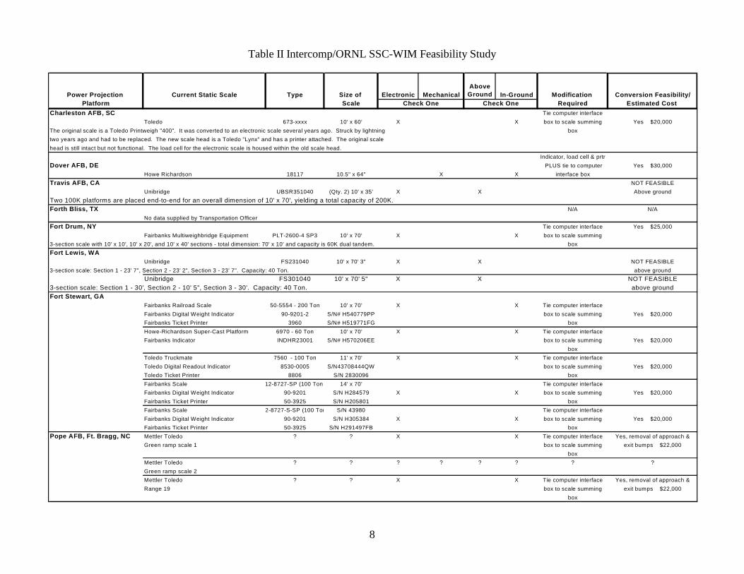
Figure 6 is a plot of the data from Table I showing the absolute error verses the total vehicle static weight for the 15 vehicle data sets. Figure 7 is a plot of the percent error versus the static weight for the same 16 vehicle data sets. One can see from these data plots that there is no bias due to the absolute weight of the vehicle and that all the variations appear to be random. By calculating the standard deviation for the 15 vehicle test runs shown in Table I and using the Student’s t-distribution we can estimate the accuracy of the WIM system of +/- 0.27% for a 65% confidence interval and +/- 0.80% for a 99% confidence interval on a per vehicle basis. These results represent a significant improvement over any commercially available weigh-in-motion system on the market today. In our AVDAC studies (2) we found that typical commercial WIM systems performed within specifications only if the vehicles being measured were all similar, such as all tractor-trailers, and were calibrated to these specific type vehicles. When different types of vehicles such as the wide variety of vehicles used in the armed forces were tested, the error rates due to variability increases by a factor of four. The accuracy obtained with our SSC-WIM system represents a factor of five better than the ASTM Standard for Type IV WIM system designated as a weight enforcement station (1). The SSC-WIM system requires only two persons to operate. As referenced in the Automated Vehicle Data Acquisition System (AVDAC) report (2) a WIM system, during a simulated deployment exercise greatly simplified the weighing operation and reduced the time required to complete the weighing operation by a factor of six. Furthermore, by eliminating the manual use of individual wheel scales, tape measures, and data sheet, one can reduce the manpower required and eliminate most of the human errors introduced by these manual operations and transfer of data. The weight-determining algorithm takes advantage of the fact that by first determining the individual axle weights and then summing them to determine the overall vehicle weight, the individual errors when averaged together result in an increased accuracy for the total vehicle weight. These results are extremely encouraging and show that a static scale can be converted to a highly accurate, low-speed WIM system with an accuracy comparable to the scale used in the static mode. It is the desire of the ORNL to pursue the development of such a system and we believe that by incorporating some additional hardware and further studying and developing a more advanced algorithm that a static scale converted WIM system could be used to make measurements on both the axle set and vehicle basis with an accuracy error of better than 1%. 2. The Static Scale Conversion to Weigh-In-Motion System was demonstrated on May 22, 2000 to Col. Dennis Sheraden and Lt. Col. Mark Surina of the AMBL. Also demonstrated was the lightweight portable WIM prototype system developed for the Air Force Productivity, Reliability, Availability, and Maintainability (PRAM) office. Both systems performed well and demonstrated how WIM technology can greatly improve the current deployment operation. 3. Intercomp, performed a survey/study of eight Power Projection Bases. The results of the survey are shown in Table II. The table provides the following information: the current static scale(s) present at the facility, type of scale, size of the scale, whether it is electronic or mechanical, whether it is in-ground or above ground, what modification(s) would be required to convert the scale to a WIM system, and what the estimated cost of conversion would be once a final commercial system was developed. Note that in the present configuration the above ground units cannot be converted to a WIM system. The present unit demonstrated the feasibility and potential of the SSC-WIM system. The final step required prior to having commercially available units is the development and demonstration of a commercial prototype system. The costs estimated in Table II are the costs of reproducing a commercial unit. The initial

7
commercial prototype unit would require additional funding to harden and commercialize the electronics and various hardware components. Furthermore a soldier-proof, user-friendly user interface needs to be developed and tested. Finally, the commercial prototype design would require certification testing of the system with both commercial and military vehicles. 4. This report meets the requirements of the final documentation.
8
Table II Intercomp/ORNL SSC-WIM Feasibility Study
Power Projection Current Static Scale Type Size of Electronic MechanicalAbove
Ground In-Ground Modification Conversion Feasibility/Platform Scale Required Estimated Cost
Charleston AFB, SC Tie computer interfaceToledo 673-xxxx 10' x 60' X X box to scale summing Yes $20,000
The original scale is a Toledo Printweigh "400". It was converted to an electronic scale several years ago. Struck by lightning boxtwo years ago and had to be replaced. The new scale head is a Toledo "Lynx" and has a printer attached. The original scale head is still intact but not functional. The load cell for the electronic scale is housed within the old scale head.
Indicator, load cell & prtrDover AFB, DE PLUS tie to computer Yes $30,000
Howe Richardson 18117 10.5" x 64" X X interface boxTravis AFB, CA NOT FEASIBLE
Unibridge UBSR351040 (Qty. 2) 10' x 35' X X Above groundTwo 100K platforms are placed end-to-end for an overall dimension of 10' x 70', yielding a total capacity of 200K.Forth Bliss, TX N/A N/A
No data supplied by Transportation OfficerFort Drum, NY Tie computer interface Yes $25,000
Fairbanks Multiweighbridge Equipment PLT-2600-4 SP3 10' x 70' X X box to scale summing3-section scale with 10' x 10', 10' x 20', and 10' x 40' sections - total dimension: 70' x 10' and capacity is 60K dual tandem. boxFort Lewis, WA
Unibridge FS231040 10' x 70' 3" X X NOT FEASIBLE3-section scale: Section 1 - 23' 7", Section 2 - 23' 2", Section 3 - 23' 7". Capacity: 40 Ton. above ground
Unibridge FS301040 10' x 70' 5" X X NOT FEASIBLE3-section scale: Section 1 - 30', Section 2 - 10' 5", Section 3 - 30'. Capacity: 40 Ton. above groundFort Stewart, GA
Fairbanks Railroad Scale 50-5554 - 200 Ton 10' x 70' X X Tie computer interfaceFairbanks Digital Weight Indicator 90-9201-2 S/N# H540779PP box to scale summing Yes $20,000Fairbanks Ticket Printer 3960 S/N# H519771FG boxHowe-Richardson Super-Cast Platform 6970 - 60 Ton 10' x 70' X X Tie computer interfaceFairbanks Indicator INDHR23001 S/N# H570206EE box to scale summing Yes $20,000
boxToledo Truckmate 7560 - 100 Ton 11' x 70' X X Tie computer interfaceToledo Digital Readout Indicator 8530-0005 S/N43708444QW box to scale summing Yes $20,000Toledo Ticket Printer 8806 S/N 2830096 boxFairbanks Scale 12-8727-SP (100 Ton 14' x 70' Tie computer interfaceFairbanks Digital Weight Indicator 90-9201 S/N H284579 X X box to scale summing Yes $20,000Fairbanks Ticket Printer 50-3925 S/N H205801 boxFairbanks Scale 2-8727-S-SP (100 Ton S/N 43980 Tie computer interfaceFairbanks Digital Weight Indicator 90-9201 S/N H305384 X X box to scale summing Yes $20,000Fairbanks Ticket Printer 50-3925 S/N H291497FB box
Pope AFB, Ft. Bragg, NC Mettler Toledo ? ? X X Tie computer interface Yes, removal of approach &Green ramp scale 1 box to scale summing exit bumps $22,000
boxMettler Toledo ? ? ? ? ? ? ? ?Green ramp scale 2Mettler Toledo ? ? X X Tie computer interface Yes, removal of approach &Range 19 box to scale summing exit bumps $22,000
box
Check One Check One
9
References 1. “Standard Specification for Weigh-in-Motion (WIM) Systems with User Requirements and Test
Methods”, Designation: E 1318 – 92, American Society for Testing and Materials (ASTM), January, 1993.
2. D. L. Beshears, R. N. Nodine, et al, Automated Vehicle Data Acquisition System (AVDAC),
ORNL/TM-13210, Lockheed Martin Energy Research Corporation, Oak Ridge, Tennessee, March 1996.
3. J. D. Muhs, and D. L. Beshears, Automated Vehicle Data Acquisition (AVDAC) System Definition of
Technical and Operational Requirements, ORNL-6799, Martin Marietta Energy Systems, Inc., Oak Ridge Tennessee, February 1994.
4. D. L. Beshears, G. J. Capps, et al, “A System and Method for Accurately Weighing and
Characterizing Moving Vehicles”, U.S. Patent # 5,998,741, Lockheed Martin Energy Research Corporation, Oak Ridge, Tennessee, December 7, 1999.
5. D. L. Beshears, J. D. Muhs, et al, Advanced Weigh-in-Motion System for Weighing Vehicles at High
Speeds, C/ORNL95-0364, Lockheed Martin Energy Research Corporation, Oak Ridge, Tennessee, February 1998.
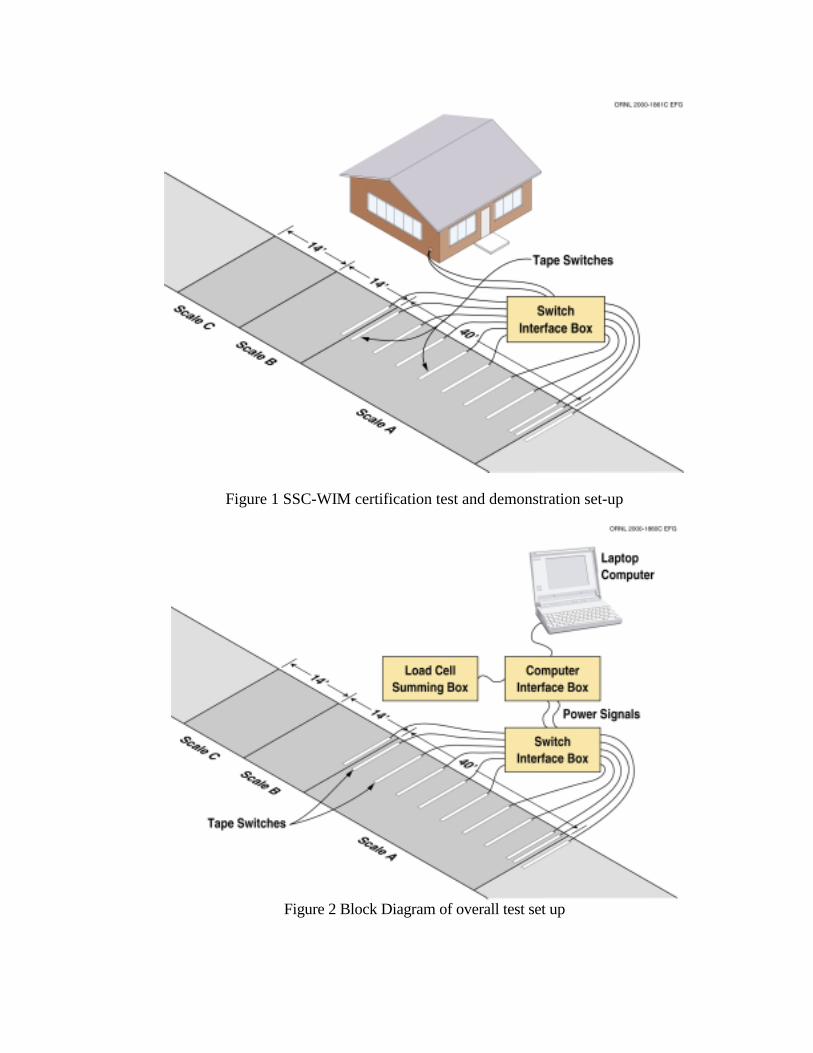
Figure 1 SSC-WIM certification test and demonstration set-up
Figure 2 Block Diagram of overall test set up
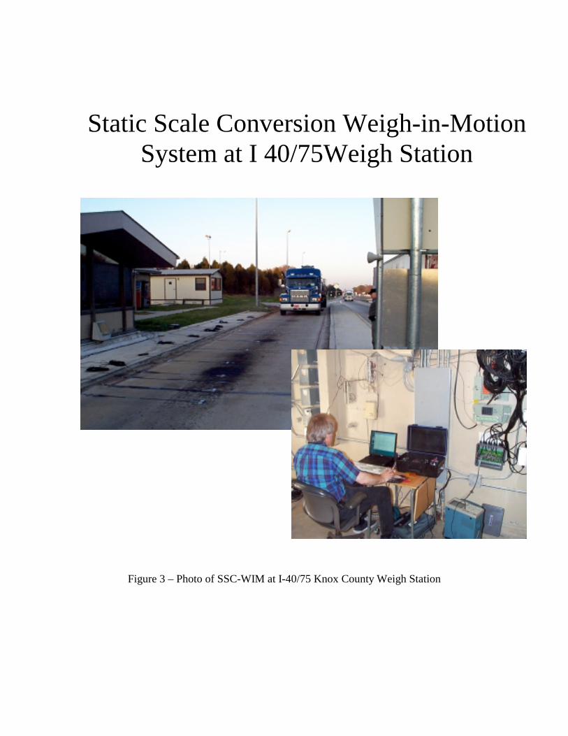
Figure 3 – Photo of SSC-WIM at I-40/75 Knox County Weigh Station
Static Scale Conversion Weigh-in-Motion System at I 40/75Weigh Station
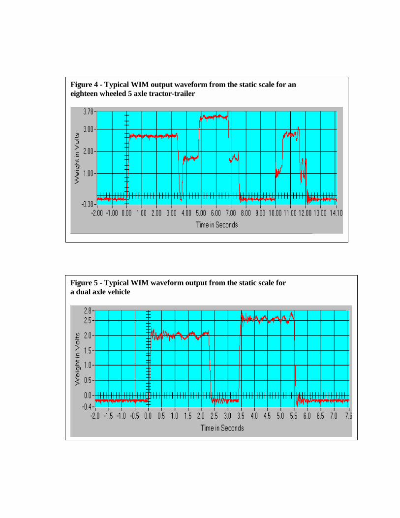
Figure 4 - Typical WIM output waveform from the static scale for an eighteen wheeled 5 axle tractor-trailer
Figure 5 - Typical WIM waveform output from the static scale for a dual axle vehicle
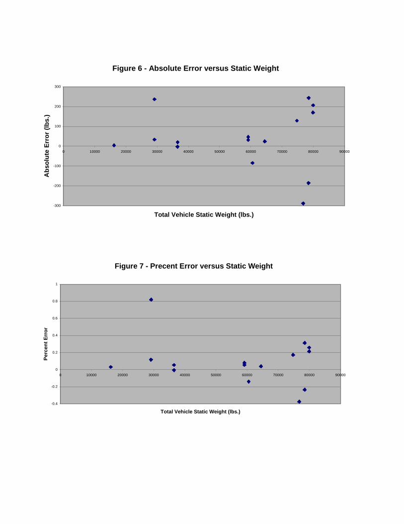
Figure 6 - Absolute Error versus Static Weight
-300
-200
-100
0
100
200
300
0 10000 20000 30000 40000 50000 60000 70000 80000 90000
Total Vehicle Static Weight (lbs.)
Abs
olut
e Er
ror (
lbs.
)
Figure 7 - Precent Error versus Static Weight
-0.4
-0.2
0
0.2
0.4
0.6
0.8
1
0 10000 20000 30000 40000 50000 60000 70000 80000 90000
Total Vehicle Static Weight (lbs.)
Perc
ent E
rror


![0006 3568(2005)055[0561-wsnfe]2.0.co;2](https://img.pdfslide.us/doc/110x75/558c867cd8b42a01078b4661/0006-356820050550561-wsnfe20co2.jpg)