Embed Size (px)
Citation preview
ADVANCED MATERIALS HANDLING
FEATURES & BENEFITS—• Small footprint preserves
valuable space on OEM equipment
• Available with normally closed or normally open actuators
• Able to withstand corrosive chemical environments
• Unique modular design improves serviceability
• Valve diaphragms successfully tested to over four million cycles for increased reliability
• Modular design enables manifold customization
• Valves offer a variety of connection options including PrimeLock, PrimeLock “SpaceSaver”, Flaretek, Flaretek “SpaceSaver”, PureBond and Super 300 Type Pillar
CR8 Manual and Pneumatic ValvesReliable service in corrosive environments for ultrapure chemical applications
Entegris has added the CR8 to its successful line of corrosion-
resistant (CR) valves. This product line offers two-way pneumatic
and manual valves for low-to-medium flow applications, with
flow factors (Cv) ranging from 1.8 – 3.4. The valves offer reliable
performance and easy serviceability – with a footprint that is
smaller than most ½” valves.
CR8 series pneumatic valves were tested to over four million
cycles to ensure reliability and reduce cost of ownership. This
proven design is available with a variety of end connection
options including PrimeLock®, Flaretek®, PureBond® and Super
300 Type Pillar®. With no exposed metal hardware, the valve is
completely sealed and protected from harsh chemical environ-
ments. These capabilities allow the CR8 series to solve a variety
of critical issues within the fab.
Ideal for wet etch and clean (WEC) and low volume bulk
chemical delivery applications, the valve line incorporates a
compact modular valve design with increased temperature
capabilities and maximized flow. CR8 series manual and
pneumatic valves are also ideal for use with Entegris Dymension®
manifolds to minimize footprint in fab equipment.
APPLICATIONS—• High-purity, corrosive
chemical handling
• Semiconductor wet clean process chemicals
• Chemical line sizes in 1⁄4” and ½” pipe, ½” and 3⁄4” tube
2
SPECIFICATIONS—
Materials All wetted parts PFA, PTFE
Exterior actuator parts PVDF, Viton®
Interior actuator parts PVDF, SST, Viton
Mounting base PVDF
Operating conditions Media pressure at 21°C (70°F) Inlet /outlet 913 mbar (27” Hg) vacuum to 552 kPa (80 psig)*
130°C (266°F) Inlet /outlet 414 kPa (60 psig)*
Actuation pressure (pneumatic version only)
414 – 552 kPa (60 – 80 psig)* All wetted parts
Temperature range Ambient 21– 50°C (70–122°F)
Fluid 21– 130°C (70– 266°F)*
Pneumatic supply port (pneumatic version only)
1⁄4” tube stub or molded female Luer lug style
Environmental compliance
RoHs, WEEE
*Actual valve performance varies with pressure and temperature; refer to actual ratings in performance data.

3
Media Temperature vs. Actuator Pilot Pressure –Normally Closed Valve
85
80
75
70
65
60
55
50
Pilo
t P
ress
ure
(kP
a)
Temperature (°C)
Acceptable actuation pressure range
20 40 60 80 100 140120
Temperature (°F)68 104 140 176 212 248 284
Pilo
t P
ress
ure
(psi
)
586
552
517
483
448
414
379
345
Med
ia P
ress
ure
(kP
a)
90
80
70
60
50
40
30
20
10
0
621
552
483
414
345
276
207
138
69
0
Acceptable operating range
20 40 60 80 100 140120Temperature (°C)
Media Temperature vs. Media Pressure
Temperature (°F)68 104 140 176 212 248 284
Med
ia P
ress
ure
(psi
)
Media Temperature vs. Actuator Pilot Pressure –Normally Open Valve
85
80
75
70
65
60
55
50
Pilo
t P
ress
ure
(kP
a)
Temperature (°C)
Acceptable actuation pressure range
20 40 60 80 100 140120
Temperature (°F)68 104 140 176 212 248 284
Pilo
t P
ress
ure
(psi
)
586
552
517
483
448
414
379
345
4.0
3.5
3.0
2.5
2.0
1.5
1.0
0.5
0
Cv
Handle Revolutions
Kv
0 1 2 3 4
CR8 Manual Multi-turn ValveC
v/K
v vs. Number of Handle Revolutions
1⁄2” Port connections
3⁄4” Port connections57.1
50.0
42.8
35.7
28.6
21.4
14.3
7.4
0
PERFORMANCE DATA—
4
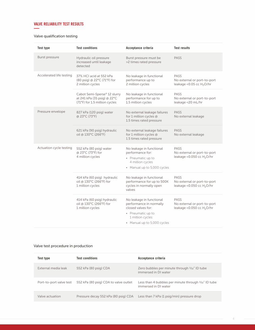
Test type Test conditions Acceptance criteria Test results
Burst pressure Hydraulic oil pressure increased until leakage detected
Burst pressure must be >2 times rated pressure
PASS
Accelerated life testing 37% HCI acid at 552 kPa (80 psig) @ 22°C (71°F) for 2 million cycles
No leakage in functional performance up to 2 million cycles
PASS No external or port-to-port leakage <0.05 cc H₂O/hr
Cabot Semi-Sperse® 12 slurry at 241 kPa (35 psig) @ 22°C (71°F) for 1.5 million cycles
No leakage in functional performance for up to 1.5 million cycles
PASS No external or port-to-port leakage <20 mL/hr
Pressure envelope 827 kPa (120 psig) water @ 23°C (73°F)
No external leakage failures for 1 million cycles @ 1.5 times rated pressure
PASS No external leakage
621 kPa (90 psig) hydraulic oil @ 130°C (266°F)
No external leakage failures for 1 million cycles @ 1.5 times rated pressure
PASS No external leakage
Actuation cycle testing 552 kPa (80 psig) water @ 23°C (73°F) for 4 million cycles
No leakage in functional performance for:
• Pneumatic up to 4 million cycles
• Manual up to 5,000 cycles
PASS No external or port-to-port leakage <0.050 cc H2O/hr
414 kPa (60 psig) hydraulic oil @ 130°C (266°F) for 1 million cycles
No leakage in functional performance for up to 500K cycles in normally open valves
PASS No external or port-to-port leakage <0.050 cc H2O/hr
414 kPa (60 psig) hydraulic oil @ 130°C (266°F) for 1 million cycles
No leakage in functional performance in normally closed valves for:
• Pneumatic up to 1 million cycles
• Manual up to 5,000 cycles
PASS No external or port-to-port leakage <0.050 cc H2O/hr
VALVE RELIABILITY TEST RESULTS—Valve qualification testing
Test type Test conditions Acceptance criteria
External media leak 552 kPa (80 psig) CDA Zero bubbles per minute through 1⁄32” ID tube immersed in DI water
Port-to-port valve test 552 kPa (80 psig) CDA to valve outlet Less than 4 bubbles per minute through 1⁄32” ID tube immersed in DI water
Valve actuation Pressure decay 552 kPa (80 psig) CDA Less than 7 kPa (1 psig/min) pressure drop
Valve test procedure in production
5
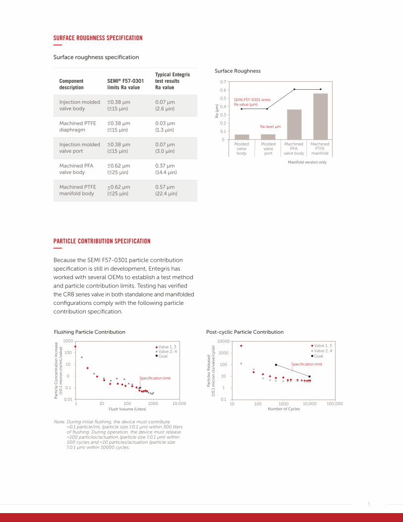
SURFACE ROUGHNESS SPECIFICATION—Surface roughness specification
Component description
SEMI® F57-0301 limits Ra value
Typical Entegris test results Ra value
Injection molded valve body
≤0.38 µm (≤15 µin)
0.07 µm (2.6 µin)
Machined PTFE diaphragm
≤0.38 µm (≤15 µin)
0.03 µm (1.3 µin)
Injection molded valve port
≤0.38 µm (≤15 µin)
0.07 µm (3.0 µin)
Machined PFA valve body
≤0.62 µm (≤25 µin)
0.37 µm (14.4 µin)
Machined PTFE manifold body
≤0.62 µm (≤25 µin)
0.57 µm (22.4 µin)
PARTICLE CONTRIBUTION SPECIFICATION—Because the SEMI F57-0301 particle contribution
specification is still in development, Entegris has
worked with several OEMs to establish a test method
and particle contribution limits. Testing has verified
the CR8 series valve in both standalone and manifolded
configurations comply with the following particle
contribution specification.
0.7
0.6
0.5
0.4
0.3
0.2
0.1
0Molded
valvebody
Moldedvalveport
MachinedPFA
valve body
MachinedPTFE
manifold
Ra
(µm
)
Surface Roughness
SEMI F57-0301 limits Ra value (µm)
Ra (ave) µm
Manifold version only
Note: During initial flushing, the device must contribute <0.1 particle/mL (particle size ≥0.1 µm) within 300 liters of flushing. During operation, the device must release <100 particles/actuation (particle size ≥0.1 µm) within 500 cycles and <10 particles/actuation (particle size ≥0.1 µm) within 10000 cycles.
Post-cyclic Particle Contribution
10000
1000
100
10
1
0.1
Par
ticl
es R
elea
sed
(≥0
.1 m
icro
n c
ts/v
alve
/cyc
le)
Specification limit
10 100 1000 10,000 100,000Number of Cycles
Valve 1, 3Valve 2, 4Goal
Flushing Particle Contribution
1000
100
10
0
0.1
0.01Par
ticl
e C
on
cen
trat
ion
Incr
ease
(≥0
.1 m
icro
n c
ts/m
L/va
lve)
Specification limit
Valve 1, 3Valve 2, 4Goal
1 10 100 1000 10,000Flush Volume (Liters)
6
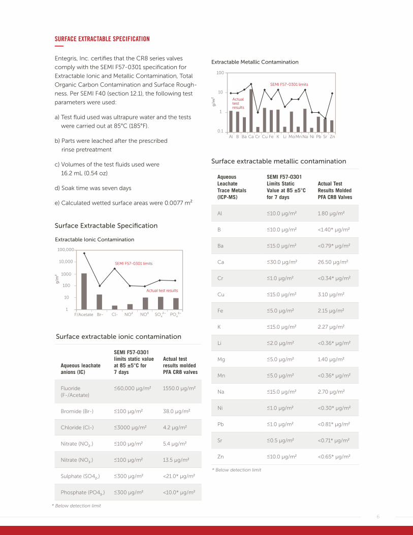
SURFACE EXTRACTABLE SPECIFICATION—Entegris, Inc. certifies that the CR8 series valves
comply with the SEMI F57-0301 specification for
Extractable Ionic and Metallic Contamination, Total
Organic Carbon Contamination and Surface Rough-
ness. Per SEMI F40 (section 12.1), the following test
parameters were used:
a) Test fluid used was ultrapure water and the tests
were carried out at 85°C (185°F).
b) Parts were leached after the prescribed
rinse pretreatment
c) Volumes of the test fluids used were
16.2 mL (0.54 oz)
d) Soak time was seven days
e) Calculated wetted surface areas were 0.0077 m²
Extractable Ionic Contamination
F/Acetate Br- Cl- NO² NO³ SO4²- PO
4³-
Actual test results
SEMI F57-0301 limits
100,000
10,000
1000
100
10
1
g/m
²
Surface Extractable Specification
Aqueous leachate anions (IC)
SEMI F57-0301 limits static value at 85 ±5°C for 7 days
Actual test results molded PFA CR8 valves
Fluoride (F-/Acetate)
≤60,000 µg/m2 1550.0 µg/m2
Bromide (Br-) ≤100 µg/m2 38.0 µg/m2
Chloride (Cl-) ≤3000 µg/m2 4.2 µg/m2
Nitrate (NO2-) ≤100 µg/m2 5.4 µg/m2
Nitrate (NO3-) ≤100 µg/m2 13.5 µg/m2
Sulphate (SO42-) ≤300 µg/m2 <21.0* µg/m2
Phosphate (PO43-) ≤300 µg/m2 <10.0* µg/m2
Surface extractable ionic contamination
* Below detection limit
100
10
1
0.1
Extractable Metallic Contamination
Al B Ba Ca Cr Cu Fe K Li Mg MnNa Ni Pb Sr Zn
Actualtestresults
SEMI F57-0301 limits
g/m
²
Aqueous Leachate Trace Metals (ICP-MS)
SEMI F57-0301 Limits Static Value at 85 ±5°C for 7 days
Actual Test Results Molded PFA CR8 Valves
Al ≤10.0 µg/m2 1.80 µg/m2
B ≤10.0 µg/m2 <1.40* µg/m2
Ba ≤15.0 µg/m2 <0.79* µg/m2
Ca ≤30.0 µg/m2 26.50 µg/m2
Cr ≤1.0 µg/m2 <0.34* µg/m2
Cu ≤15.0 µg/m2 3.10 µg/m2
Fe ≤5.0 µg/m2 2.15 µg/m2
K ≤15.0 µg/m2 2.27 µg/m2
Li ≤2.0 µg/m2 <0.36* µg/m2
Mg ≤5.0 µg/m2 1.40 µg/m2
Mn ≤5.0 µg/m2 <0.36* µg/m2
Na ≤15.0 µg/m2 2.70 µg/m2
Ni ≤1.0 µg/m2 <0.30* µg/m2
Pb ≤1.0 µg/m2 <0.81* µg/m2
Sr ≤0.5 µg/m2 <0.71* µg/m2
Zn ≤10.0 µg/m2 <0.65* µg/m2
Surface extractable metallic contamination
* Below detection limit
7
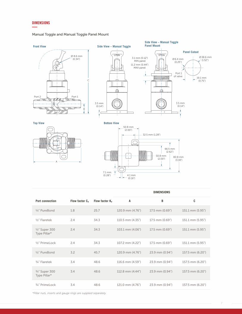
DIMENSIONS—Manual Toggle and Manual Toggle Panel Mount
C
Port 2
Ø 8.6 mm (0.34”)
Front View
3.5 mm(0.14”)
Port 1
Side View – Manual ToggleSide View – Manual TogglePanel Mount
3.1 mm (0.12”)MIN panel
11.2 mm (0.44”)MAX panel
Ø38.6 mm(1.52”)Ø6.4 mm
(0.25”)
Port 1 of valve
19.1 mm(0.75”)
Panel Cutout
3.5 mm(0.14”)
Top View Bottom View
A
4.1 mm(0.16”)
7.1 mm(0.28”)
80.8 mm (3.18”)
66.5 mm (2.62”)
50.8 mm (2.00”)
50.8 mm (2.00”)
32.5 mm (1.28”)
B
DIMENSIONS
Port connection Flow factor Cv Flow factor Kv A B C
1⁄4” PureBond 1.8 25.7 120.9 mm (4.76”) 17.5 mm (0.69”) 151.1 mm (5.95”)
1⁄2” Flaretek 2.4 34.3 110.5 mm (4.35”) 17.5 mm (0.69”) 151.1 mm (5.95”)
1⁄2” Super 300 Type Pillar*
2.4 34.3 103.1 mm (4.06”) 17.5 mm (0.69”) 151.1 mm (5.95”)
1⁄2” PrimeLock 2.4 34.3 107.2 mm (4.22”) 17.5 mm (0.69”) 151.1 mm (5.95”)
1⁄2” PureBond 3.2 45.7 120.9 mm (4.76”) 23.9 mm (0.94”) 157.5 mm (6.20”)
3⁄4” Flaretek 3.4 48.6 116.6 mm (4.59”) 23.9 mm (0.94”) 157.5 mm (6.20”)
3⁄4” Super 300 Type Pillar*
3.4 48.6 112.8 mm (4.44”) 23.9 mm (0.94”) 157.5 mm (6.20”)
3⁄4” PrimeLock 3.4 48.6 121.0 mm (4.76”) 23.9 mm (0.94”) 157.5 mm (6.20”)
*Pillar nuts, inserts and gauge rings are supplied separately.
8
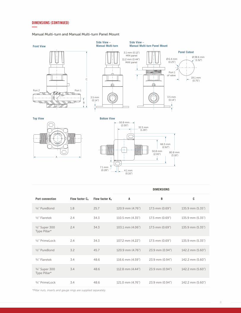
DIMENSIONS (CONTINUED)—Manual Multi-turn and Manual Multi-turn Panel Mount
DIMENSIONS
Port connection Flow factor Cv Flow factor Kv A B C
1⁄4” PureBond 1.8 25.7 120.9 mm (4.76”) 17.5 mm (0.69”) 135.9 mm (5.35”)
1⁄2” Flaretek 2.4 34.3 110.5 mm (4.35”) 17.5 mm (0.69”) 135.9 mm (5.35”)
1⁄2” Super 300 Type Pillar*
2.4 34.3 103.1 mm (4.06”) 17.5 mm (0.69”) 135.9 mm (5.35”)
1⁄2” PrimeLock 2.4 34.3 107.2 mm (4.22”) 17.5 mm (0.69”) 135.9 mm (5.35”)
1⁄2” PureBond 3.2 45.7 120.9 mm (4.76”) 23.9 mm (0.94”) 142.2 mm (5.60”)
3⁄4” Flaretek 3.4 48.6 116.6 mm (4.59”) 23.9 mm (0.94”) 142.2 mm (5.60”)
3⁄4” Super 300 Type Pillar*
3.4 48.6 112.8 mm (4.44”) 23.9 mm (0.94”) 142.2 mm (5.60”)
3⁄4” PrimeLock 3.4 48.6 121.0 mm (4.76”) 23.9 mm (0.94”) 142.2 mm (5.60”)
*Pillar nuts, inserts and gauge rings are supplied separately.
Top View
4.1 mm(0.16”)
7.1 mm(0.28”)
80.8 mm (3.18”)
66.5 mm (2.62”)
50.8 mm (2.00”)
Bottom View
32.5 mm (1.28”)
50.8 mm (2.00”)
3.5 mm(0.14”)
Side View – Manual Multi-turn Panel Mount
Side View – Manual Multi-turn
Panel Cutout
Ø 38.6 mm(1.52”)Ø 6.4 mm
(0.25”)
19.1 mm(0.75”)
Port 1 of valve
3.1 mm (0.12”)MIN panel
11.2 mm (0.44”)MAX panel
3.5 mm(0.14”)
A
Front View
Port 2 Port 1
B
C
9
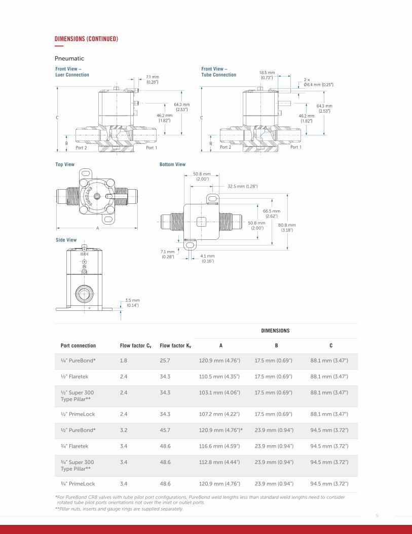
DIMENSIONS (CONTINUED)—Pneumatic
DIMENSIONS
Port connection Flow factor Cv Flow factor Kv A B C
1⁄4” PureBond* 1.8 25.7 120.9 mm (4.76”) 17.5 mm (0.69”) 88.1 mm (3.47”)
1⁄2” Flaretek 2.4 34.3 110.5 mm (4.35”) 17.5 mm (0.69”) 88.1 mm (3.47”)
1⁄2” Super 300 Type Pillar**
2.4 34.3 103.1 mm (4.06”) 17.5 mm (0.69”) 88.1 mm (3.47”)
1⁄2” PrimeLock 2.4 34.3 107.2 mm (4.22”) 17.5 mm (0.69”) 88.1 mm (3.47”)
1⁄2” PureBond* 3.2 45.7 120.9 mm (4.76”)* 23.9 mm (0.94”) 94.5 mm (3.72”)
3⁄4” Flaretek 3.4 48.6 116.6 mm (4.59”) 23.9 mm (0.94”) 94.5 mm (3.72”)
3⁄4” Super 300 Type Pillar**
3.4 48.6 112.8 mm (4.44”) 23.9 mm (0.94”) 94.5 mm (3.72”)
3⁄4” PrimeLock 3.4 48.6 120.9 mm (4.76”) 23.9 mm (0.94”) 94.5 mm (3.72”)
* For PureBond CR8 valves with tube pilot port configurations, PureBond weld lengths less than standard weld lengths need to consider rotated tube pilot ports orientations not over the inlet or outlet ports.
**Pillar nuts, inserts and gauge rings are supplied separately.
Front View –Luer Connection
Front View – Tube Connection
Top View Bottom View
Side View
66.5 mm
50.8 mm (2.00”)
32.5 mm (1.28”)
80.8 mm
(2.62”)
50.8 mm
(3.18”)(2.00”)
4.1 mm7.1 mm
(0.16”)(0.28”)
3.5 mm(0.14”)
A
10
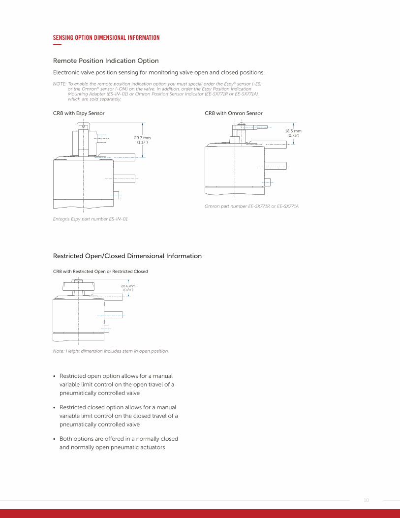
SENSING OPTION DIMENSIONAL INFORMATION—
Remote Position Indication Option
Electronic valve position sensing for monitoring valve open and closed positions.
NOTE: To enable the remote position indication option you must special order the Espy® sensor (-ES) or the Omron® sensor (-OM) on the valve. In addition, order the Espy Position Indication Mounting Adapter (ES-IN-01) or Omron Position Sensor Indicator (EE-SX771R or EE-SX771A), which are sold separately.
29.7 mm(1.17”)
CR8 with Espy Sensor
18.5 mm (0.73”)
CR8 with Omron Sensor
Entegris Espy part number ES-IN-01
Omron part number EE-SX771R or EE-SX771A
Restricted Open/Closed Dimensional Information
20.6 mm (0.81”)
CR8 with Restricted Open or Restricted Closed
Note: Height dimension includes stem in open position.
• Restricted open option allows for a manual
variable limit control on the open travel of a
pneumatically controlled valve
• Restricted closed option allows for a manual
variable limit control on the closed travel of a
pneumatically controlled valve
• Both options are offered in a normally closed
and normally open pneumatic actuators
11
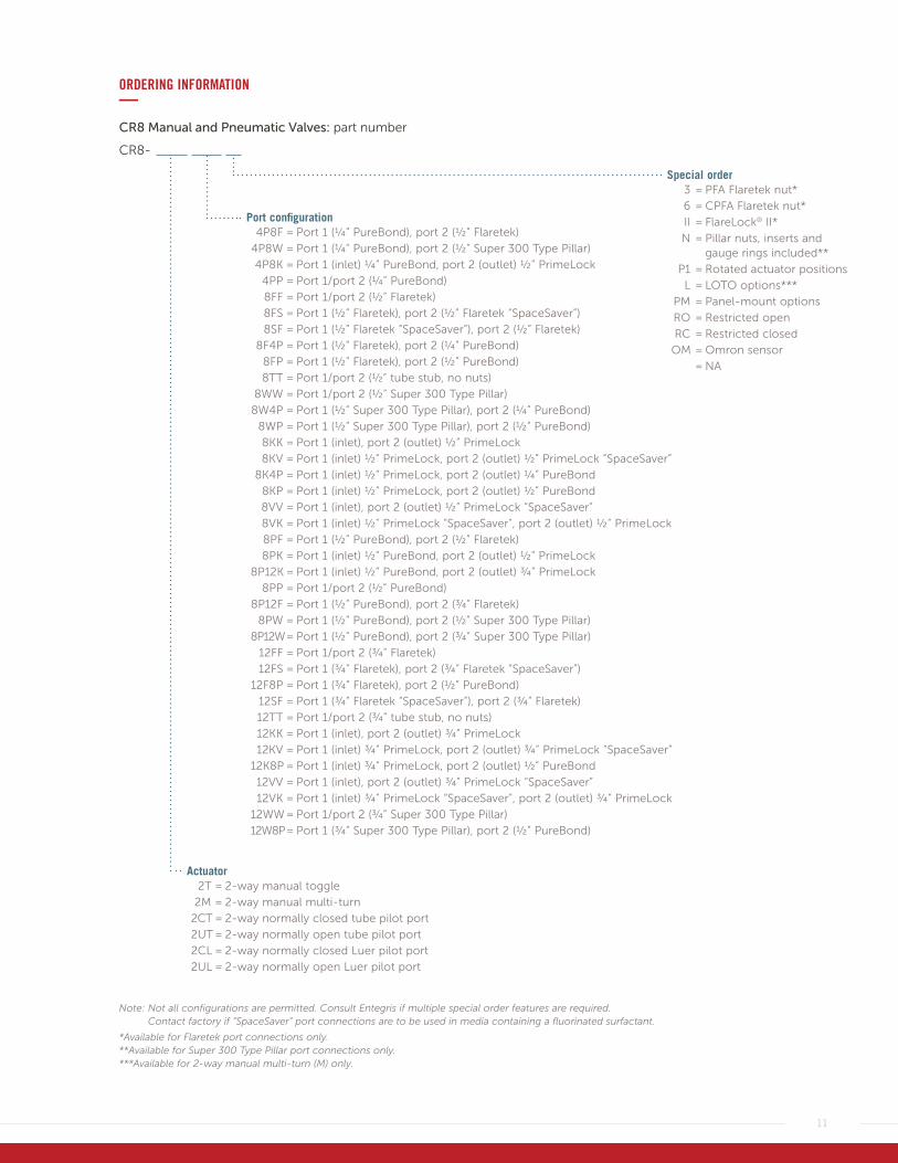
ORDERING INFORMATION—CR8 Manual and Pneumatic Valves: part number
CR8-
Actuator 2T = 2-way manual toggle
2M = 2-way manual multi-turn
2CT = 2-way normally closed tube pilot port
2UT = 2-way normally open tube pilot port
2CL = 2-way normally closed Luer pilot port
2UL = 2-way normally open Luer pilot port
Port configuration 4P8F = Port 1 (¼” PureBond), port 2 (½” Flaretek)
4P8W = Port 1 (¼” PureBond), port 2 (½” Super 300 Type Pillar)
4P8K = Port 1 (inlet) ¼” PureBond, port 2 (outlet) ½” PrimeLock
4PP = Port 1 / port 2 (¼” PureBond)
8FF = Port 1 / port 2 (½” Flaretek)
8FS = Port 1 (½” Flaretek), port 2 (½” Flaretek “SpaceSaver”)
8SF = Port 1 (½” Flaretek “SpaceSaver”), port 2 (½” Flaretek)
8F4P = Port 1 (½” Flaretek), port 2 (¼” PureBond)
8FP = Port 1 (½” Flaretek), port 2 (½” PureBond)
8TT = Port 1 /port 2 (½” tube stub, no nuts)
8WW = Port 1 / port 2 (½” Super 300 Type Pillar)
8W4P = Port 1 (½” Super 300 Type Pillar), port 2 (¼” PureBond)
8WP = Port 1 (½” Super 300 Type Pillar), port 2 (½” PureBond)
8KK = Port 1 (inlet), port 2 (outlet) ½” PrimeLock
8KV = Port 1 (inlet) ½” PrimeLock, port 2 (outlet) ½” PrimeLock “SpaceSaver”
8K4P = Port 1 (inlet) ½” PrimeLock, port 2 (outlet) ¼” PureBond
8KP = Port 1 (inlet) ½” PrimeLock, port 2 (outlet) ½” PureBond
8V V = Port 1 (inlet), port 2 (outlet) ½” PrimeLock “SpaceSaver”
8VK = Port 1 (inlet) ½” PrimeLock “SpaceSaver”, port 2 (outlet) ½” PrimeLock
8PF = Port 1 (½” PureBond), port 2 (½” Flaretek)
8PK = Port 1 (inlet) ½” PureBond, port 2 (outlet) ½” PrimeLock
8P12K = Port 1 (inlet) ½” PureBond, port 2 (outlet) ¾” PrimeLock
8PP = Port 1 /port 2 (½” PureBond)
8P12F = Port 1 (½” PureBond), port 2 (¾” Flaretek)
8PW = Port 1 (½” PureBond), port 2 (½” Super 300 Type Pillar)
8P12W = Port 1 (½” PureBond), port 2 (¾” Super 300 Type Pillar)
12FF = Port 1 /port 2 (¾” Flaretek)
12FS = Port 1 (¾” Flaretek), port 2 (¾” Flaretek “SpaceSaver”)
12F8P = Port 1 (¾” Flaretek), port 2 (½” PureBond)
12SF = Port 1 (¾” Flaretek “SpaceSaver”), port 2 (¾” Flaretek)
12TT = Port 1 / port 2 (¾” tube stub, no nuts)
12KK = Port 1 (inlet), port 2 (outlet) ¾” PrimeLock
12KV = Port 1 (inlet) ¾” PrimeLock, port 2 (outlet) ¾” PrimeLock “SpaceSaver”
12K8P = Port 1 (inlet) ¾” PrimeLock, port 2 (outlet) ½” PureBond
12VV = Port 1 (inlet), port 2 (outlet) ¾” PrimeLock “SpaceSaver”
12VK = Port 1 (inlet) ¾” PrimeLock “SpaceSaver”, port 2 (outlet) ¾” PrimeLock
12WW = Port 1 /port 2 (¾” Super 300 Type Pillar)
12W8P = Port 1 (¾” Super 300 Type Pillar), port 2 (½” PureBond)
Special order 3 = PFA Flaretek nut*
6 = CPFA Flaretek nut*
II = FlareLock® II*
N = Pillar nuts, inserts and gauge rings included**
P1 = Rotated actuator positions
L = LOTO options***
PM = Panel-mount options
RO = Restricted open
RC = Restricted closed
OM = Omron sensor
= NA
Note: Not all configurations are permitted. Consult Entegris if multiple special order features are required. Contact factory if “SpaceSaver” port connections are to be used in media containing a fluorinated surfactant.
*Available for Flaretek port connections only. **Available for Super 300 Type Pillar port connections only. ***Available for 2-way manual multi-turn (M) only.
129 Concord RoadBillerica, MA 01821 USA
Tel +1 952 556 4181Fax +1 952 556 8022Toll Free 800 394 4083
Corporate Headquarters Customer Service
FOR MORE INFORMATION
Please call your Regional Customer Service Center today to learn what Entegris can do for you. Visit entegris.com and select the Contact Us link to find the customer service center nearest you.
TERMS AND CONDITIONS OF SALE
All purchases are subject to Entegris’ Terms and Conditions of Sale. To view and print this information, visit entegris.com and select the Terms & Conditions link in the footer.
www.entegris.com
Entegris®, the Entegris Rings Design™, Pure Advantage™, Flaretek®, PrimeLock®, PureBond®, Dymension®, FlareLock® and Espy® are trademarks of Entegris, Inc.; Viton® is a registered trademark of E. I. du Pont de Nemours and Company.; Omron® is a registered trademark of Omron Corporation.; Semi-Sperse® is a registered trademark of Cabot Corporation.; SEMI® is a registered trademark of Semiconductor Equipment and Materials International Corporation.; Pillar® is a trademark of Nippon Pillar Packing Company, Ltd.
©2009-2017 Entegris, Inc. | All rights reserved. | Printed in the USA | 3210-5788ENT-0217


![Test Plant Dense Phase Pressure Pneumatic Conveying · 2019-04-02 · 28 2329 Dense Phase Pressure Pneumatic Conveying Test Plant I]Z E6A6B6I>8 EGD8:HH aVWdgVidgn [dg edlYZgh lVh](https://img.pdfslide.us/doc/110x75/5f5efd5733afe60b2209b0bb/test-plant-dense-phase-pressure-pneumatic-conveying-2019-04-02-28-2329-dense-phase.jpg)


![PRESSURE TESTING [1] การตรวจสอบโดยใช้แรงดัน · pressure testing into 2 cases: 1. Hydrostatic Pressure Test. 2. Pneumatic Pressure Test](https://img.pdfslide.us/doc/110x75/5e6f0cdaf382de6744014cfb/pressure-testing-1-aaaaaaaaaaaaaafaaaaaaaa.jpg)