Embed Size (px)
Citation preview
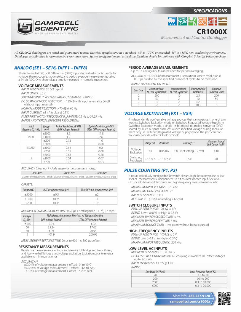
SPECIFICATIONS
CR1000XMeasurement and Control Datalogger
campbellsci.com/cr1000x
More info: 435.227.9120
ANALOG (SE1 – SE16, DIFF1 – DIFF8)16 single-ended (SE) or 8 Differential (DIFF) inputs individually configurable for voltage, thermocouple, ratiometric, and period average measurements, using a 24-bit ADC. One channel at a time is measured in numeric succession.
VOLTAGE MEASUREMENTSINPUT RESISTANCE: 20 GΩ typicalINPUT LIMITS: ±5 VSUSTAINED INPUT VOLTAGE WITHOUT DAMAGE: ±20 VdcDC COMMON MODE REJECTION: > 120 dB with input reversal (≥ 86 dB without input reversal)NORMAL MODE REJECTION: > 70 dB @ 60 HzINPUT CURRENT: ±1 nA typical @ 25°CFILTER FIRST NOTCH FREQUENCY (fN1) RANGE: 0.5 Hz to 31.25 kHzRANGE AND TYPICAL EFFECTIVE RESOLUTION:
Notch Frequency (fN1 )
1 (Hz) Range 2
(mv)Typical Resolution, µV RMS
(DIFF w/Input Reversal)Typical Resolution, µV RMS
(SE or DIFF w/o Input Reversal)
15000±5000 8.2 11.8±1000 1.9 2.6±200 0.75 1.0
50/603±5000 0.6 0.88±1000 0.14 0.2±200 0.05 0.08
5±5000 0.18 0.28±1000 0.04 0.07±200 0.02 0.03
ACCURACY (does not include sensor or measurement noise):
0° to 40°C -40° to 70°C -55° to 85°C±(0.04% of measurement + offset) ±(0.06% of measurement + offset) ±(0.08% of measurement + offset)
OFFSETS:
Range (mV) DIFF w/Input Reversal (μV) SE or DIFF w/o Input Reversal (μV)
±5000 ±0.5 ±2±1000 ±0.25 ±1±200 ±0.15 ±0.5
MULTIPLEXED MEASUREMENT TIME: (450 µs + settling time + (1/fN1)) * reps
Example fN 1 (Hz)4
Multiplexed Measurement Time (ms) w/ 500 µs settling time DIFF w/Input Reversal SE or DIFF w/o Input Reversal
15000 2.04 1.0260 35.24 17.6250 41.9 20.955 401.9 200.95
MEASUREMENT SETTLING TIME: 20 µs to 600 ms; 500 µs default
RESISTANCE MEASUREMENTSResistance measurements for four- and six-wire full bridge and two-, three-, and four-wire half bridge using voltage excitation. Excitation polarity reversal available to minimize dc error.
ACCURACY:5,6
±(0.01% of voltage measurement + offset) , 0° to 40°C ±(0.015% of voltage measurement + offset), -40° to 70°C ±(0.02% of voltage measurement + offset , -55° to 85°C
PERIOD AVERAGE MEASUREMENTSUp to 16 analog inputs can be used for period averaging.
ACCURACY: ±(0.01% of measurement + resolution), where resolution is 0.13 μs divided by the specified number of cycles to be measured.
RANGE DEPENDENT ON INPUT:
Gain Code Minimum Peak- to-Peak Signal (mV)7
Maximum Peak- to-Peak Signal (V)8
Minimum Pulse Width (µs)
Maximum Frequency (kHz)9
0 500 10 2.5 2001 50 2 10 502 10 2 62 83 2 2 100 5
VOLTAGE EXCITATION (VX1 – VX4)4 independently configurable voltage sources that can operate in one of two modes: Switched Excitation mode or Switched Regulated Voltage Supply. In Switched Excitation mode, a single 16-bit digital-to-analog converter (DAC) shared by all VX outputs produces a user-specified voltage during measure-ment only. In Switched Regulated Voltage Supply mode, the port can con-tinuously provide either 3.3 Vdc or 5 Vdc.
Range (V) Resolution Accuracy6,10 Maximum Source/Sink Current (mA)11
Voltage Excitation ±4 0.06 mV ±(0.1% of setting + 2 mV) ±40
Switched, Regulated +3.3 or 5 +3.3 or 5 V ±5% 50
PULSE COUNTING (P1, P2)2 inputs individually configurable for switch closure, high-frequency pulse, or low-level AC measurements. Independent 32-bit counter for each input. See also C1 - C8 for additional switch closure and high-frequency measurement inputs.
MAXIMUM INPUT VOLTAGE: ±20 VdcMAXIMUM COUNT PER SCAN: 232
INPUT RESISTANCE: 5 kΩACCURACY: ±(0.02% of reading +1/scan)
SWITCH CLOSURE INPUTSPULL-UP RESISTANCE: 100 kΩ to 5 VEVENT: Low (<0.8 V) to High (>2.5 V)MINIMUM SWITCH CLOSED TIME: 5 msMINIMUM SWITCH OPEN TIME: 6 msMAXIMUM BOUNCE TIME: 1 ms open without being counted
HIGH-FREQUENCY INPUTSPULL-UP RESISTANCE: 100 kΩ to 5 VEVENT: Low (<0.8 V) to High (>2.5 V)MAXIMUM INPUT FREQUENCY: 250 kHz
LOW-LEVEL AC INPUTSMINIMUM RESISTANCE: 10 kΩ to G DC-OFFSET REJECTION: Internal AC coupling eliminates DC-offset voltages up to ±0.5 VdcINPUT HYSTERESIS: 12 mV @ 1 HzRANGE:
Sine Wave (mV RMS) Input Frequency Range( Hz)20 1.0 to 20
200 0.5 to 2002000 0.3 to 10,0005000 0.3 to 20,000
All CR1000X dataloggers are tested and guaranteed to meet electrical specifications in a standard -40° to +70°C or extended -55° to +85°C non-condensing environment. Datalogger recalibration is recommended every three years. System configuration and critical specifications should be confirmed with Campbell Scientific before purchase.
815 W 1800 N | Logan, UT 84321-1784 | 435.227.9120 | www.campbellsci.comUSA | AUSTRALIA | BRAZIL | CANADA | CHINA | COSTA RICA | FRANCE | GERMANY | SE ASIA | SOUTH AFRICA | SPAIN | UK
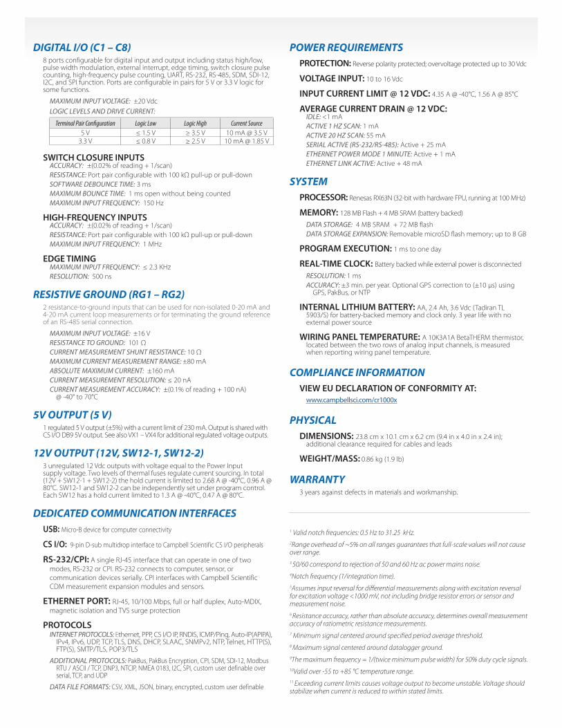
DIGITAL I/O (C1 – C8)8 ports configurable for digital input and output including status high/low, pulse width modulation, external interrupt, edge timing, switch closure pulse counting, high-frequency pulse counting, UART, RS-232, RS-485, SDM, SDI-12, I2C, and SPI function. Ports are configurable in pairs for 5 V or 3.3 V logic for some functions.
MAXIMUM INPUT VOLTAGE: ±20 VdcLOGIC LEVELS AND DRIVE CURRENT:
Terminal Pair Configuration Logic Low Logic High Current Source5 V ≤ 1.5 V ≥ 3.5 V 10 mA @ 3.5 V
3.3 V ≤ 0.8 V ≥ 2.5 V 10 mA @ 1.85 V
SWITCH CLOSURE INPUTSACCURACY: ±(0.02% of reading + 1/scan) RESISTANCE: Port pair configurable with 100 kΩ pull-up or pull-downSOFTWARE DEBOUNCE TIME: 3 msMAXIMUM BOUNCE TIME: 1 ms open without being countedMAXIMUM INPUT FREQUENCY: 150 Hz
HIGH-FREQUENCY INPUTSACCURACY: ±(0.02% of reading + 1/scan) RESISTANCE: Port pair configurable with 100 kΩ pull-up or pull-downMAXIMUM INPUT FREQUENCY: 1 MHz
EDGE TIMINGMAXIMUM INPUT FREQUENCY: ≤ 2.3 KHz RESOLUTION: 500 ns
RESISTIVE GROUND (RG1 – RG2) 2 resistance-to-ground inputs that can be used for non-isolated 0-20 mA and 4-20 mA current loop measurements or for terminating the ground reference of an RS-485 serial connection.
MAXIMUM INPUT VOLTAGE: ±16 VRESISTANCE TO GROUND: 101 ΩCURRENT MEASUREMENT SHUNT RESISTANCE: 10 ΩMAXIMUM CURRENT MEASUREMENT RANGE: ±80 mAABSOLUTE MAXIMUM CURRENT: ±160 mACURRENT MEASUREMENT RESOLUTION: ≤ 20 nACURRENT MEASUREMENT ACCURACY: ±(0.1% of reading + 100 nA) @ -40° to 70°C
5V OUTPUT (5 V)1 regulated 5 V output (±5%) with a current limit of 230 mA. Output is shared with CS I/O DB9 5V output. See also VX1 – VX4 for additional regulated voltage outputs.
12V OUTPUT (12V, SW12-1, SW12-2)3 unregulated 12 Vdc outputs with voltage equal to the Power Input supply voltage. Two levels of thermal fuses regulate current sourcing. In total (12V + SW12-1 + SW12-2) the hold current is limited to 2.68 A @ -40°C, 0.96 A @ 80°C. SW12-1 and SW12-2 can be independently set under program control. Each SW12 has a hold current limited to 1.3 A @ -40°C, 0.47 A @ 80°C.
DEDICATED COMMUNICATION INTERFACESUSB: Micro-B device for computer connectivity
CS I/O: 9-pin D-sub multidrop interface to Campbell Scientific CS I/O peripherals
RS-232/CPI: A single RJ-45 interface that can operate in one of two modes, RS-232 or CPI. RS-232 connects to computer, sensor, or communication devices serially. CPI interfaces with Campbell Scientific CDM measure ment expansion modules and sensors.
ETHERNET PORT: RJ-45, 10/100 Mbps, full or half duplex, Auto-MDIX, magnetic isolation and TVS surge protection
PROTOCOLS INTERNET PROTOCOLS: Ethernet, PPP, CS I/O IP, RNDIS, ICMP/Ping, Auto-IP(APIPA), IPv4, IPv6, UDP, TCP, TLS, DNS, DHCP, SLAAC, SNMPv2, NTP, Telnet, HTTP(S), FTP(S), SMTP/TLS, POP3/TLS
ADDITIONAL PROTOCOLS: PakBus, PakBus Encryption, CPI, SDM, SDI-12, Modbus RTU / ASCII / TCP, DNP3, NTCIP, NMEA 0183, I2C, SPI, custom user definable over serial, TCP, and UDP
DATA FILE FORMATS: CSV, XML, JSON, binary, encrypted, custom user definable
POWER REQUIREMENTSPROTECTION: Reverse polarity protected; overvoltage protected up to 30 Vdc
VOLTAGE INPUT: 10 to 16 Vdc
INPUT CURRENT LIMIT @ 12 VDC: 4.35 A @ -40°C, 1.56 A @ 85°C
AVERAGE CURRENT DRAIN @ 12 VDC: IDLE: <1 mAACTIVE 1 HZ SCAN: 1 mAACTIVE 20 HZ SCAN: 55 mASERIAL ACTIVE (RS-232/RS-485): Active + 25 mAETHERNET POWER MODE 1 MINUTE: Active + 1 mAETHERNET LINK ACTIVE: Active + 48 mA
SYSTEMPROCESSOR: Renesas RX63N (32-bit with hardware FPU, running at 100 MHz)
MEMORY: 128 MB Flash + 4 MB SRAM (battery backed) DATA STORAGE: 4 MB SRAM + 72 MB flashDATA STORAGE EXPANSION: Removable microSD flash memory; up to 8 GB
PROGRAM EXECUTION: 1 ms to one day
REAL-TIME CLOCK: Battery backed while external power is disconnected
RESOLUTION: 1 ms ACCURACY: ±3 min. per year. Optional GPS correction to (±10 µs) using GPS, PakBus, or NTP
INTERNAL LITHIUM BATTERY: AA, 2.4 Ah, 3.6 Vdc (Tadiran TL 5903/S) for battery-backed memory and clock only. 3 year life with no external power source
WIRING PANEL TEMPERATURE: A 10K3A1A BetaTHERM thermistor, located between the two rows of analog input channels, is measured when reporting wiring panel temperature.
COMPLIANCE INFORMATIONVIEW EU DECLARATION OF CONFORMITY AT: www.campbellsci.com/cr1000x
PHYSICALDIMENSIONS: 23.8 cm x 10.1 cm x 6.2 cm (9.4 in x 4.0 in x 2.4 in); additional clearance required for cables and leads
WEIGHT/MASS: 0.86 kg (1.9 lb)
WARRANTY3 years against defects in materials and workmanship.
1 Valid notch frequencies: 0.5 Hz to 31.25 kHz.2Range overhead of ~5% on all ranges guarantees that full-scale values will not cause over range. 3 50/60 correspond to rejection of 50 and 60 Hz ac power mains noise. 4Notch frequency (1/integration time). 5Assumes input reversal for differential measurements along with excitation reversal for excitation voltage <1000 mV, not including bridge resistor errors or sensor and measurement noise. 6 Resistance accuracy, rather than absolute accuracy, determines overall measurement accuracy of ratiometric resistance measurements.7 Minimum signal centered around specified period average threshold.8 Maximum signal centered around datalogger ground. 9The maximum frequency = 1/(twice minimum pulse width) for 50% duty cycle signals. 10Valid over -55 to +85 °C temperature range.11 Exceeding current limits causes voltage output to become unstable. Voltage should stabilize when current is reduced to within stated limits.

815 W 1800 N | Logan, UT 84321-1784 | 435.227.9120 | www.campbellsci.comUSA | AUSTRALIA | BRAZIL | CANADA | CHINA | COSTA RICA | FRANCE | GERMANY | SE ASIA | SOUTH AFRICA | SPAIN | UK
TERMINALSAnalog Input SE1 SE2 SE3 SE4 SE5 SE6 SE7 SE8 SE9 SE10 SE11 SE12 SE13 SE14 SE15 SE16 RG1 RG2 Max
Single Ended 16Differential H L H L H L H L H L H L H L H L 8Ratiometric Bridge 16Thermocouple 16Current Loop 2Period Average 16
Analog Output VX1 VX2 VX3 VX4 Max
Switched-Voltage Excitation 4
Voltage Output12 C1 C2 C3 C4 C5 C6 C7 C8 VX1 VX2 VX3 VX4 5 V 12V SW12V-1 SW12V-2 Max
5 V 93.3 V 812 V 3
Communication13 C1 C2 C3 C4 C5 C6 C7 C8 RS-232/CPI USB Ethernet CS I/O Max
SDI-12 4GPS PPS Rx Tx Rx Tx Rx Tx Rx 1TTL (0 to 5 V) Tx Rx Tx Rx Tx Rx Tx Rx 4LVTTL (0 to 3.3 V) Tx Rx Tx Rx Tx Rx Tx Rx 4RS-232 Tx Rx Tx Rx 3RS-485 (Half Duplex) A(-) B(+) A(-) B(+) 2RS-485 (Full Duplex) Tx- Tx+ Rx- Rx+ 1I2C SDA SCL SDA SCL SDA SCL SDA SCL 4SPI MOSI SCLK MISO MOSI SCLK MISO 2SDM14 DATA CLK ENABLE DATA CLK ENABLE 1CPI/CDM 1USB 1Ethernet 1CS I/O 1
Digital I/O13 C1 C2 C3 C4 C5 C6 C7 C8 Max
General I/O Pair 8Pulse-Width Modulation Output 8Timer Input 8Interrupt 8
Pulse Counting13 C1 C2 C3 C4 C5 C6 C7 C8 P1 P2 Max
Switch Closure 10High Frequency 10Low Level AC 2
12 For the Voltage Outputs, the C terminals have limited drive capacity and the voltage levels are configured in pairs.13 Triggering conflicts can occur when companion control ports are used for different triggering instructions (TimerInput, PulseCount, SDI12Recorder, WaitDigTrig). For example, if C3 is used for the SDI12Recorder instruction, C4 cannot be used in the TimerInput, PulseCount, or WaitDigTrig instructions. 14 SDM can be on either C1-C3 or C5-C7, but not both at the same time.
815 W 1800 N | Logan, UT 84321-1784 | 435.227.9120 | www.campbellsci.comUSA | AUSTRALIA | BRAZIL | CANADA | CHINA | COSTA RICA | FRANCE | GERMANY | SE ASIA | SOUTH AFRICA | SPAIN | UK
© 2017Campbell Scientific, Inc.
November 1, 2017
Campbell Scientific, Inc. | 815 W 1800 N | Logan, UT 84321-1784 | (435) 227-9120 | www.campbellsci.comUSA | AUSTRALIA | BRAZIL | CANADA | CHINA | COSTA RICA | FRANCE | GERMANY | SE ASIA | SOUTH AFRICA | SPAIN | UK815 W 1800 N | Logan, UT 84321-1784 | 435.227.9120 | www.campbellsci.com
USA | AUSTRALIA | BRAZIL | CANADA | CHINA | COSTA RICA | FRANCE | GERMANY | SE ASIA | SOUTH AFRICA | SPAIN | UK
INFO
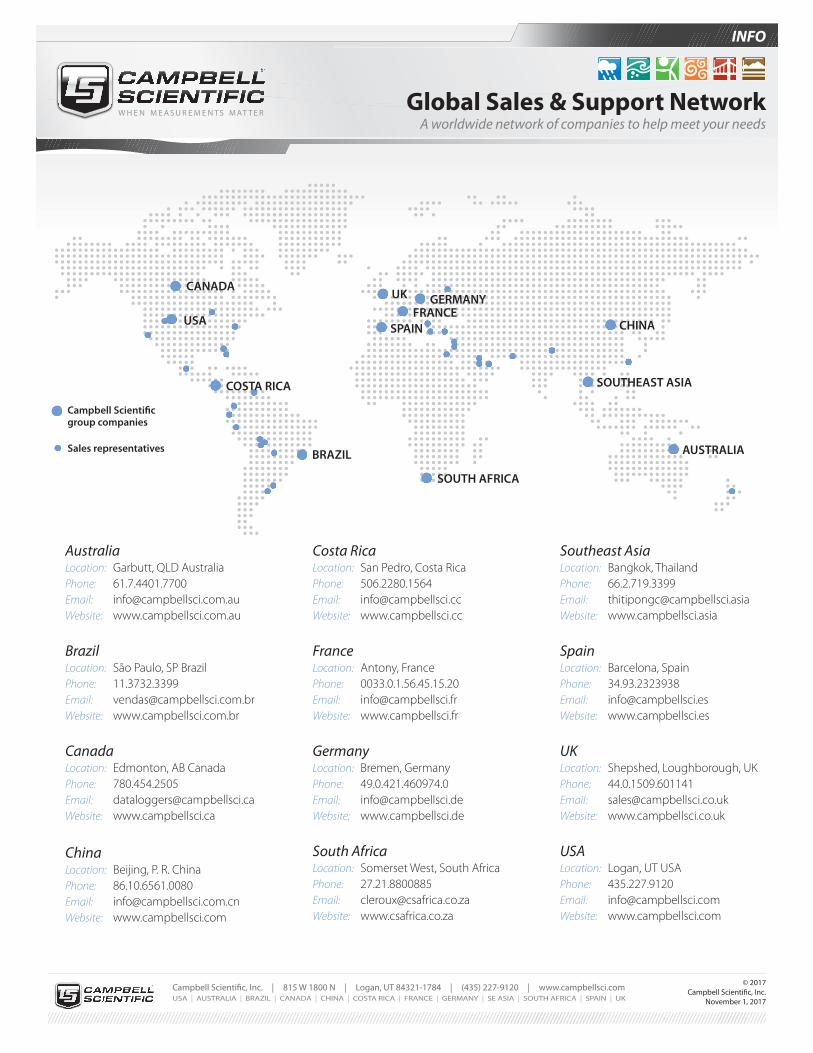
Global Sales & Support NetworkA worldwide network of companies to help meet your needs
www.campbellsci.com/directory
More info: 435.227.9120
AustraliaLocation: Garbutt, QLD Australia Phone: 61.7.4401.7700 Email: [email protected] Website: www.campbellsci.com.au
BrazilLocation: São Paulo, SP Brazil Phone: 11.3732.3399 Email: [email protected] Website: www.campbellsci.com.br
CanadaLocation: Edmonton, AB Canada Phone: 780.454.2505 Email: [email protected] Website: www.campbellsci.ca
ChinaLocation: Beijing, P. R. China Phone: 86.10.6561.0080 Email: [email protected] Website: www.campbellsci.com
Costa RicaLocation: San Pedro, Costa Rica Phone: 506.2280.1564 Email: [email protected] Website: www.campbellsci.cc
FranceLocation: Antony, France Phone: 0033.0.1.56.45.15.20 Email: [email protected] Website: www.campbellsci.fr
GermanyLocation: Bremen, Germany Phone: 49.0.421.460974.0 Email: [email protected] Website: www.campbellsci.de
South AfricaLocation: Somerset West, South Africa Phone: 27.21.8800885 Email: [email protected] Website: www.csafrica.co.za
Southeast AsiaLocation: Bangkok, Thailand Phone: 66.2.719.3399 Email: [email protected] Website: www.campbellsci.asia
SpainLocation: Barcelona, Spain Phone: 34.93.2323938 Email: [email protected] Website: www.campbellsci.es
UKLocation: Shepshed, Loughborough, UK Phone: 44.0.1509.601141 Email: [email protected] Website: www.campbellsci.co.uk
USALocation: Logan, UT USA Phone: 435.227.9120 Email: [email protected] Website: www.campbellsci.com
CANADAUK
FRANCE
SOUTH AFRICA
BRAZIL AUSTRALIA
SPAINUSA
GERMANY
CHINA
Campbell Scientific group companies
Sales representatives
COSTA RICA
Other Locations: Sales and support are provided in many other locations through an extensive network of international reps. For the full list, please visit www.campbellsci.com/directory.
SOUTHEAST ASIA