Embed Size (px)
Citation preview
CPU 317T-3PN/DP: Controlling a
SINAMICS S120
___________________
___________________
___________________
___________________
___________________
___________________
___________________
SIMATIC
S7 300 Automation Systems CPU 317T-3PN/DP: Controlling a SINAMICS S120
Getting Started
10/2013 A5E00480391-06
Introduction 1
Preparation 2
Wiring 3
Configuration 4
Programming 5
Trial run 6
Special case - controlling a virtual axis
7
Siemens AG Industry Sector Postfach 48 48 90026 NÜRNBERG GERMANY
A5E00480391-06 Ⓟ 09/2013 Technical data subject to change
Copyright © Siemens AG 2005 - 2013. All rights reserved
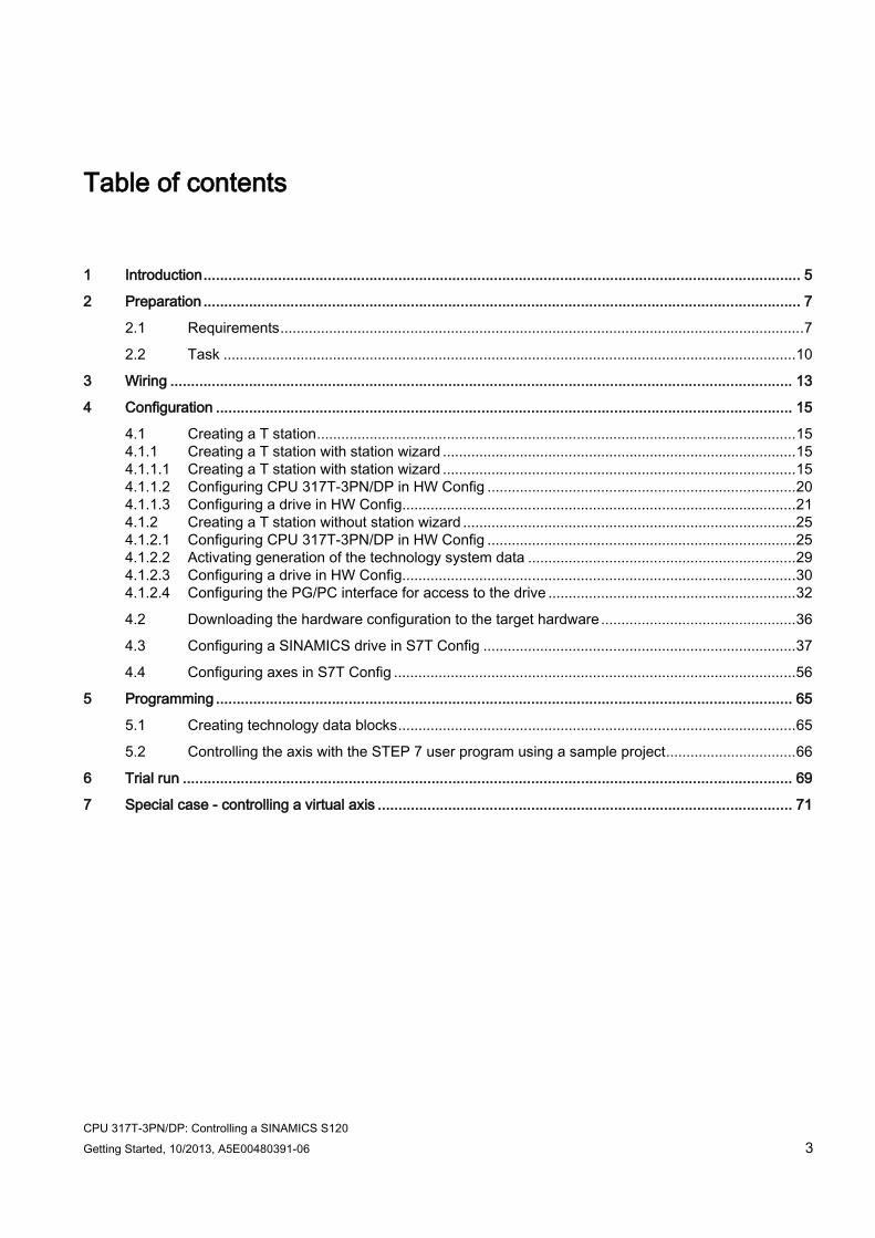
Legal information Warning notice system
This manual contains notices you have to observe in order to ensure your personal safety, as well as to prevent damage to property. The notices referring to your personal safety are highlighted in the manual by a safety alert symbol, notices referring only to property damage have no safety alert symbol. These notices shown below are graded according to the degree of danger.
DANGER indicates that death or severe personal injury will result if proper precautions are not taken.
WARNING indicates that death or severe personal injury may result if proper precautions are not taken.
CAUTION indicates that minor personal injury can result if proper precautions are not taken.
NOTICE indicates that property damage can result if proper precautions are not taken.
If more than one degree of danger is present, the warning notice representing the highest degree of danger will be used. A notice warning of injury to persons with a safety alert symbol may also include a warning relating to property damage.
Qualified Personnel The product/system described in this documentation may be operated only by personnel qualified for the specific task in accordance with the relevant documentation, in particular its warning notices and safety instructions. Qualified personnel are those who, based on their training and experience, are capable of identifying risks and avoiding potential hazards when working with these products/systems.
Proper use of Siemens products Note the following:
WARNING Siemens products may only be used for the applications described in the catalog and in the relevant technical documentation. If products and components from other manufacturers are used, these must be recommended or approved by Siemens. Proper transport, storage, installation, assembly, commissioning, operation and maintenance are required to ensure that the products operate safely and without any problems. The permissible ambient conditions must be complied with. The information in the relevant documentation must be observed.
Trademarks All names identified by ® are registered trademarks of Siemens AG. The remaining trademarks in this publication may be trademarks whose use by third parties for their own purposes could violate the rights of the owner.
Disclaimer of Liability We have reviewed the contents of this publication to ensure consistency with the hardware and software described. Since variance cannot be precluded entirely, we cannot guarantee full consistency. However, the information in this publication is reviewed regularly and any necessary corrections are included in subsequent editions.
CPU 317T-3PN/DP: Controlling a SINAMICS S120 Getting Started, 10/2013, A5E00480391-06 3
Table of contents
1 Introduction ................................................................................................................................................ 5
2 Preparation ................................................................................................................................................ 7
2.1 Requirements ................................................................................................................................. 7
2.2 Task ............................................................................................................................................. 10
3 Wiring ...................................................................................................................................................... 13
4 Configuration ........................................................................................................................................... 15
4.1 Creating a T station ...................................................................................................................... 15 4.1.1 Creating a T station with station wizard ....................................................................................... 15 4.1.1.1 Creating a T station with station wizard ....................................................................................... 15 4.1.1.2 Configuring CPU 317T-3PN/DP in HW Config ............................................................................ 20 4.1.1.3 Configuring a drive in HW Config................................................................................................. 21 4.1.2 Creating a T station without station wizard .................................................................................. 25 4.1.2.1 Configuring CPU 317T-3PN/DP in HW Config ............................................................................ 25 4.1.2.2 Activating generation of the technology system data .................................................................. 29 4.1.2.3 Configuring a drive in HW Config................................................................................................. 30 4.1.2.4 Configuring the PG/PC interface for access to the drive ............................................................. 32
4.2 Downloading the hardware configuration to the target hardware ................................................ 36
4.3 Configuring a SINAMICS drive in S7T Config ............................................................................. 37
4.4 Configuring axes in S7T Config ................................................................................................... 56
5 Programming ........................................................................................................................................... 65
5.1 Creating technology data blocks .................................................................................................. 65
5.2 Controlling the axis with the STEP 7 user program using a sample project ................................ 66
6 Trial run ................................................................................................................................................... 69
7 Special case - controlling a virtual axis .................................................................................................... 71

Table of contents
CPU 317T-3PN/DP: Controlling a SINAMICS S120 4 Getting Started, 10/2013, A5E00480391-06
CPU 317T-3PN/DP: Controlling a SINAMICS S120 Getting Started, 10/2013, A5E00480391-06 5
Introduction 1
This Getting Started is a valuable help in getting started with the basic functions of a CPU 317T-3PN/DP, based on a practical example that takes you through thirteen steps in commissioning a fully functional application in which you execute a traverse motion.
It can take you between two and three hours to work through the example, depending on your degree of experience.
Requirement
Note
This Getting Started presumes that you have connected a SINAMICS S120 drive to the DP(DRIVE) interface of the CPU 317T-3PN/DP. You can also connect a different drive, the theoretical procedure remains the same.
If you use a different drive type, an additional software program can be required for the configuration and commissioning of the drive: For example, for SIMODRIVE 611U you additionally require the software SimoComU. Always take the associated technical information of the drive into account.
If a drive is not available, we recommend that you work with a virtual axis as described in chapter "Special case - controlling a virtual axis (Page 71)".
Validity The manual is valid for the following components:
● CPU 317T-3PN/DP as of V3.2.9/4.1.5
● SINAMICS S120 as of V4.4
● S7 Technology as of V4.2 SP3
Note
You can also use the CPU 317T-3PN/DP instead of the CPU 315T-3PN/DP. To do this, select CPU 315T-3PN/DP in HW Config. Otherwise, the configuring steps are the same.

Introduction
CPU 317T-3PN/DP: Controlling a SINAMICS S120 6 Getting Started, 10/2013, A5E00480391-06
CPU 317T-3PN/DP: Controlling a SINAMICS S120 Getting Started, 10/2013, A5E00480391-06 7
Preparation 2 2.1 Requirements
Requirements The following requirements must be fulfilled:
● You have an S7-300 station, consisting of:
– Power supply (PS), e.g., 6ES7307-1KA02-0AA0
– CPU 317T-3PN/DP with MMC (8 MB or more), e.g., 6ES7317-7TK10-0AB0 V3.2/V4.1.5
– Optional digital input module (DI) with bus connector, for example, 6ES7321-1BH02-0AA0
– Optional digital output module (DO) with bus connector, for example, 6ES7322-1BH01-0AA0
– Two optional front connectors for the digital modules
● The following software packages and commissioning tools are correctly installed on your programming device with Ethernet interface:
– STEP 7 as of V5.5 SP2
– S7 Technology as of V4.2 SP3
● The programming device is connected via Ethernet interface to the CPU:
– Ethernet cable IE TP Cord RJ45/RJ45 TP cable 4 x 2 with 2 RJ45 plug-in connectors
0.5 m 6XV1 870-3QE50
1 m 6XV1 870-3QH10
2 m 6XV1 870-3QH20
6 m 6XV1 870-3QH60
10 m 6XV1 870-3QN10
● A SINAMICS S120 is connected to the CPU 317T-3PN/DP via the DP(DRIVE) interface.
– PROFIBUS cable, e.g., 6ES7901-4BD00-0XA0
Preparation 2.1 Requirements
CPU 317T-3PN/DP: Controlling a SINAMICS S120 8 Getting Started, 10/2013, A5E00480391-06
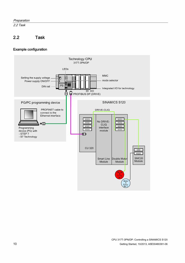
● The SINAMICS S120 comprises the following modules:
– CU320-2DP Control Unit (6SL3040-1MA00-0AA0) with TB30 Terminal Board (6SL3055-0AA00-2TA0)
– Smart Line Module 5 kW (6SL3130-6AE15-0AB1)
– Single/Double Motor Module 3 A (6SL3120-2TE13-0AA4)
– 1 synchronous motor 1FK7022-5AK71-1AG3 with incremental encoder sin/cos 1 Vpp via SMC20 Sensor Module Cabinet (6SL3055-0AA00-5BA1)
– 1 synchronous motor 1FK7022-5AK71-1LG3 with DRIVE-CLiQ interface: Absolute encoder EnDat 512 pulses/revolution
– Reference loops for position monitoring
– Control box for setpoint/actual-value linkage via terminals
● SINAMICS S120 has the factory settings.
● You know the firmware version of your SINAMICS S120.
If you do not know the firmware version, then you can find the version on the supplied certificate. Alternatively, you can open the "content.txt" file on the CF card. The firmware version is in the "Internal Version" entry. You can find more detailed information on reading the firmware version in the SINAMICS S120 product information.
Note
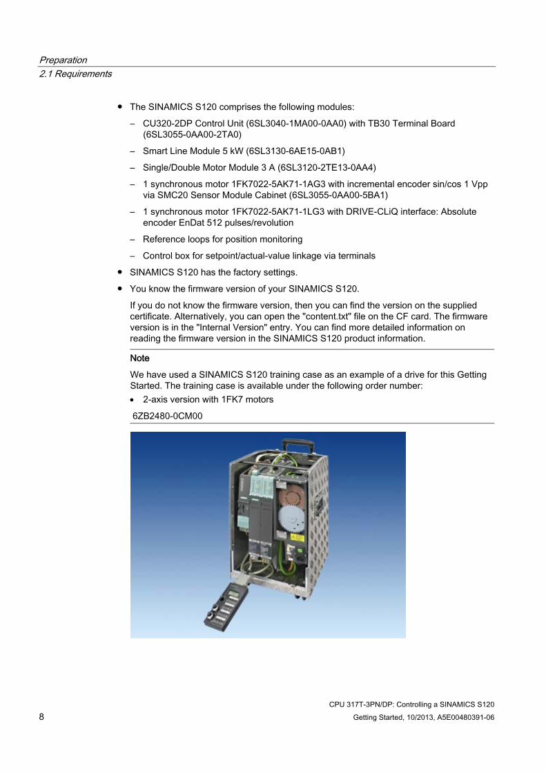
We have used a SINAMICS S120 training case as an example of a drive for this Getting Started. The training case is available under the following order number: • 2-axis version with 1FK7 motors
6ZB2480-0CM00
Preparation 2.1 Requirements
CPU 317T-3PN/DP: Controlling a SINAMICS S120 Getting Started, 10/2013, A5E00480391-06 9
● The configuration is completely installed and wired. For information, refer to Getting Started CPU 31x: Commissioning.
● You provided hardware limit switches and EMERGENCY-OFF switches for safe and reliable operation of the system.
WARNING
Risk of accident
Operation of an S7-300 as part of plants or systems is subject to special rules and regulations, based on its field of application.
You risk severe injury, or damage to machines and equipment if you ignore these directives.
Please note the current safety regulations for the prevention of accidents, e.g. IEC 204 (EMERGENCY-OFF equipment).
Preparation 2.2 Task
CPU 317T-3PN/DP: Controlling a SINAMICS S120 10 Getting Started, 10/2013, A5E00480391-06
2.2 Task
Example configuration
Preparation 2.2 Task
CPU 317T-3PN/DP: Controlling a SINAMICS S120 Getting Started, 10/2013, A5E00480391-06 11
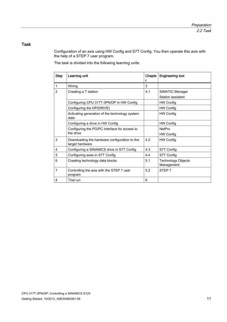
Task Configuration of an axis using HW Config and S7T Config. You then operate this axis with the help of a STEP 7 user program.
The task is divided into the following learning units:
Step Learning unit Chapte
r Engineering tool
1 Wiring 3 2 Creating a T station 4.1 SIMATIC Manager
Station assistant Configuring CPU 317T-3PN/DP in HW Config HW Config Configuring the DP(DRIVE) HW Config Activating generation of the technology system data
HW Config
Configuring a drive in HW Config HW Config Configuring the PG/PC interface for access to the drive
NetPro HW Config
3 Downloading the hardware configuration to the target hardware
4.2 HW Config
4 Configuring a SINAMICS drive in S7T Config 4.3 S7T Config 5 Configuring axes in S7T Config 4.4 S7T Config 6 Creating technology data blocks 5.1 Technology Objects
Management 7 Controlling the axis with the STEP 7 user
program 5.2 STEP 7
8 Trial run 6

Preparation 2.2 Task
CPU 317T-3PN/DP: Controlling a SINAMICS S120 12 Getting Started, 10/2013, A5E00480391-06
CPU 317T-3PN/DP: Controlling a SINAMICS S120 Getting Started, 10/2013, A5E00480391-06 13
Wiring 3
WARNING
Live wires
You may come into contact with live wires when modules are connected to the power supply.
Always switch off power before you start wiring the S7-300. Connect only ferrules with insulating collar to the ends of the cable. When you have wired the modules, you must first close all front doors. Only then may you switch the devices back on.
Procedure A description of the installation and wiring of your CPU 317T-3PN/DP is found in the Getting Started Collection S7-300 PLC: CPU 31x: Commissioning.
Wiring
CPU 317T-3PN/DP: Controlling a SINAMICS S120 14 Getting Started, 10/2013, A5E00480391-06
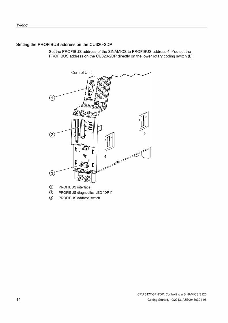
Setting the PROFIBUS address on the CU320-2DP Set the PROFIBUS address of the SINAMICS to PROFIBUS address 4. You set the PROFIBUS address on the CU320-2DP directly on the lower rotary coding switch (L).
① PROFIBUS interface ② PROFIBUS diagnostics LED "DP1" ③ PROFIBUS address switch
CPU 317T-3PN/DP: Controlling a SINAMICS S120 Getting Started, 10/2013, A5E00480391-06 15
Configuration 4 4.1 Creating a T station
In the following chapters you will configure a CPU 317T-3PN/DP. To do this, you create a T station. You can create the T station with or without station wizard.
The station wizard helps you to carry out several steps when configuring a CPU 317T-3PN/DP in one work cycle.
The configuration "with station wizard" comprises the following steps:
● Creating a T station with station wizard
● Configuring digital input and digital output module
● Configuring a drive in HW Config
The configuration "without station wizard" comprises the following steps:
● Configuring CPU 317T-3PN/DP in HW Config
● Activating generation of the technology system data
● Configuring a drive in HW Config
● Configuring the PG/PC interface for access to the drive
● Downloading the hardware configuration to the target hardware
4.1.1 Creating a T station with station wizard
4.1.1.1 Creating a T station with station wizard The station wizard helps you to carry out several steps when configuring a CPU 317T-3PN/DP in one work cycle.
Procedure Step Activity 1 Set up a new project in the SIMATIC Manager (for example, "GS_317T_3PN-DP_with_S120"). 2 Select the Insert > Station > SIMATIC T station menu command.
The "Set up T station" dialog box opens.
Configuration 4.1 Creating a T station
CPU 317T-3PN/DP: Controlling a SINAMICS S120 16 Getting Started, 10/2013, A5E00480391-06
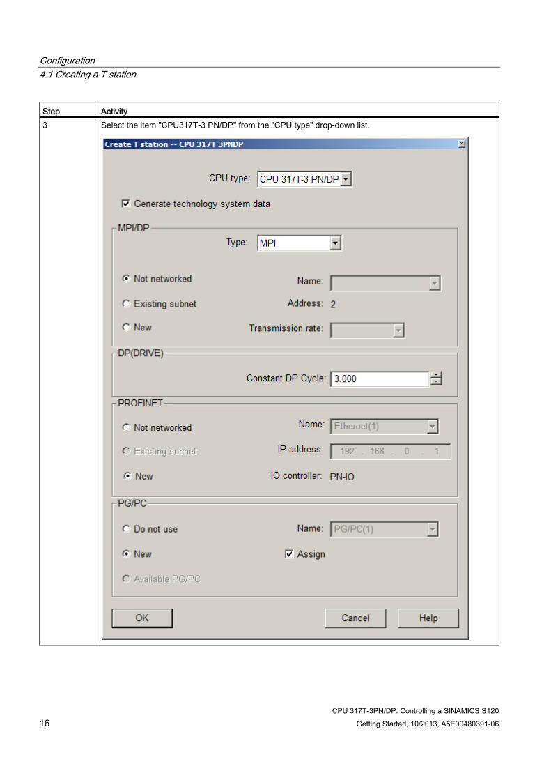
Step Activity 3 Select the item "CPU317T-3 PN/DP" from the "CPU type" drop-down list.
Configuration 4.1 Creating a T station
CPU 317T-3PN/DP: Controlling a SINAMICS S120 Getting Started, 10/2013, A5E00480391-06 17
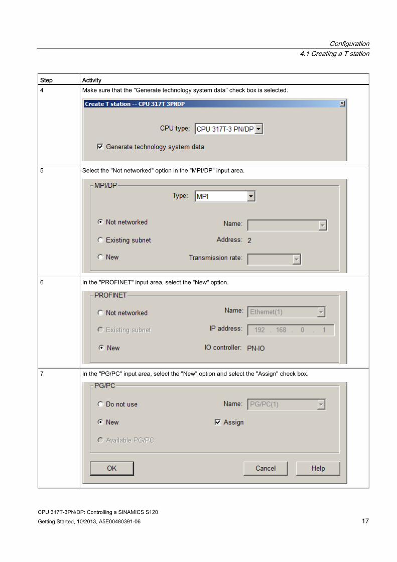
Step Activity 4 Make sure that the "Generate technology system data" check box is selected.
5 Select the "Not networked" option in the "MPI/DP" input area.
6 In the "PROFINET" input area, select the "New" option.
7 In the "PG/PC" input area, select the "New" option and select the "Assign" check box.
Configuration 4.1 Creating a T station
CPU 317T-3PN/DP: Controlling a SINAMICS S120 18 Getting Started, 10/2013, A5E00480391-06
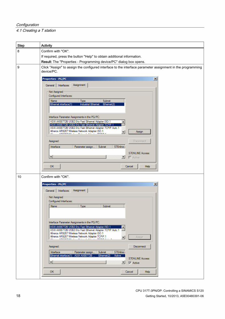
Step Activity 8 Confirm with "OK".
If required, press the button "Help" to obtain additional information. Result: The "Properties - Programming device/PC" dialog box opens.
9 Click "Assign" to assign the configured interface to the interface parameter assignment in the programming device/PC.
10 Confirm with "OK".
Configuration 4.1 Creating a T station
CPU 317T-3PN/DP: Controlling a SINAMICS S120 Getting Started, 10/2013, A5E00480391-06 19
See also Configuring a drive in HW Config (Page 30)
Configuration 4.1 Creating a T station
CPU 317T-3PN/DP: Controlling a SINAMICS S120 20 Getting Started, 10/2013, A5E00480391-06
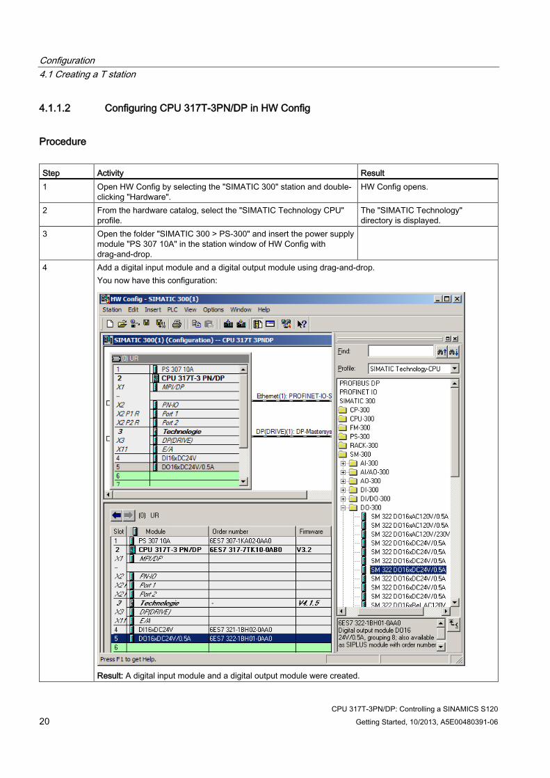
4.1.1.2 Configuring CPU 317T-3PN/DP in HW Config
Procedure Step Activity Result 1 Open HW Config by selecting the "SIMATIC 300" station and double-
clicking "Hardware". HW Config opens.
2 From the hardware catalog, select the "SIMATIC Technology CPU" profile.
The "SIMATIC Technology" directory is displayed.
3 Open the folder "SIMATIC 300 > PS-300" and insert the power supply module "PS 307 10A" in the station window of HW Config with drag-and-drop.
4 Add a digital input module and a digital output module using drag-and-drop. You now have this configuration:
Result: A digital input module and a digital output module were created.
Configuration 4.1 Creating a T station
CPU 317T-3PN/DP: Controlling a SINAMICS S120 Getting Started, 10/2013, A5E00480391-06 21
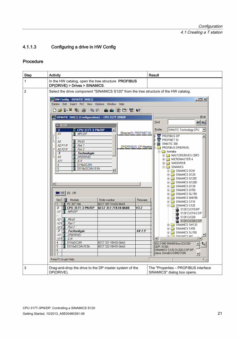
4.1.1.3 Configuring a drive in HW Config
Procedure Step Activity Result 1 In the HW catalog, open the tree structure PROFIBUS
DP(DRIVE) > Drives > SINAMICS.
2 Select the drive component "SINAMICS S120" from the tree structure of the HW catalog.
3 Drag-and-drop the drive to the DP master system of the
DP(DRIVE). The "Properties – PROFIBUS interface SINAMICS" dialog box opens.
Configuration 4.1 Creating a T station
CPU 317T-3PN/DP: Controlling a SINAMICS S120 22 Getting Started, 10/2013, A5E00480391-06
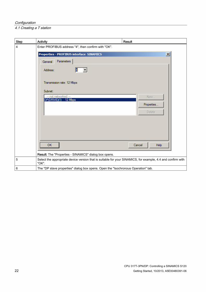
Step Activity Result 4 Enter PROFIBUS address "4", then confirm with "OK".
Result: The "Properties - SINAMICS" dialog box opens.
5 Select the appropriate device version that is suitable for your SINAMICS, for example, 4.4 and confirm with "OK".
6 The "DP slave properties" dialog box opens. Open the "Isochronous Operation" tab.
Configuration 4.1 Creating a T station
CPU 317T-3PN/DP: Controlling a SINAMICS S120 Getting Started, 10/2013, A5E00480391-06 23
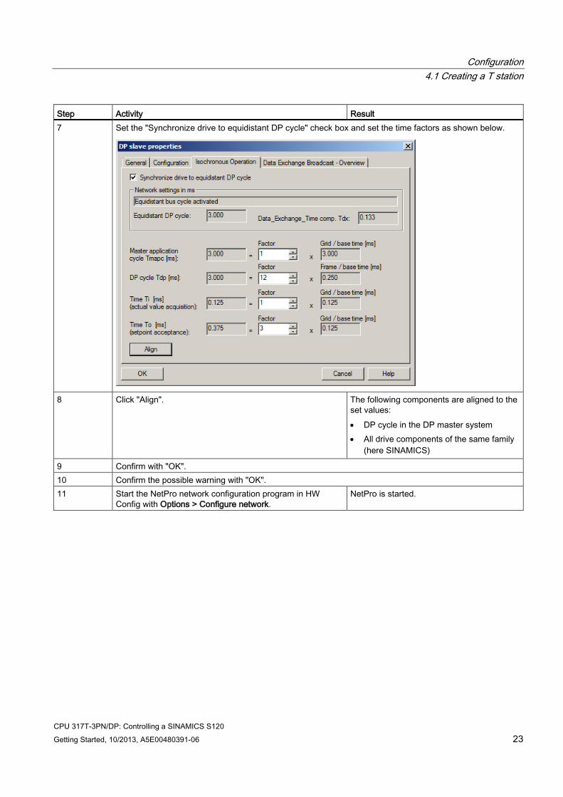
Step Activity Result 7 Set the "Synchronize drive to equidistant DP cycle" check box and set the time factors as shown below.
8 Click "Align". The following components are aligned to the
set values: • DP cycle in the DP master system • All drive components of the same family
(here SINAMICS)
9 Confirm with "OK". 10 Confirm the possible warning with "OK". 11 Start the NetPro network configuration program in HW
Config with Options > Configure network. NetPro is started.
Configuration 4.1 Creating a T station
CPU 317T-3PN/DP: Controlling a SINAMICS S120 24 Getting Started, 10/2013, A5E00480391-06
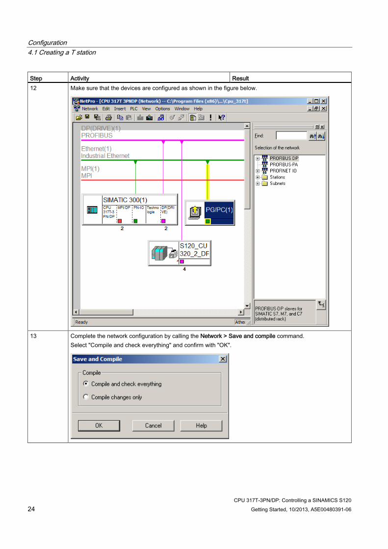
Step Activity Result 12 Make sure that the devices are configured as shown in the figure below.
13 Complete the network configuration by calling the Network > Save and compile command.
Select "Compile and check everything" and confirm with "OK".
Configuration 4.1 Creating a T station
CPU 317T-3PN/DP: Controlling a SINAMICS S120 Getting Started, 10/2013, A5E00480391-06 25
Step Activity Result 14 Close the output window with File > Close. 15 Close the NetPro configuration program by calling the Network > Exit command. 16 Finalize your HW configuration by calling the Station > Save
and compile command. The system compiles your project, and adds the "Technology Objects" object to the project window in SIMATIC Manager.
4.1.2 Creating a T station without station wizard
4.1.2.1 Configuring CPU 317T-3PN/DP in HW Config
Procedure Step Activity Result 1 Create a new project in the SIMATIC Manager (for example,
"GS_317T_3PN-DP_with_S120") and add a SIMATIC 300 station. The SIMATIC 300 station is displayed in SIMATIC Manager.
2 Open HW Config by selecting the "SIMATIC 300" station and double-clicking "Hardware".
HW Config opens.
3 From the hardware catalog, select the "SIMATIC Technology CPU" profile.
The "SIMATIC Technology" directory is displayed.
4 Open the folder "SIMATIC 300 > RACK-300" and insert a mounting rail in the station window of HW Config with drag-and-drop.
This creates a mounting rail.
5 Drag-and-drop the "PS 307 10A" power supply module onto the mounting rail.
The power supply module appears on the mounting rail.
Configuration 4.1 Creating a T station
CPU 317T-3PN/DP: Controlling a SINAMICS S120 26 Getting Started, 10/2013, A5E00480391-06
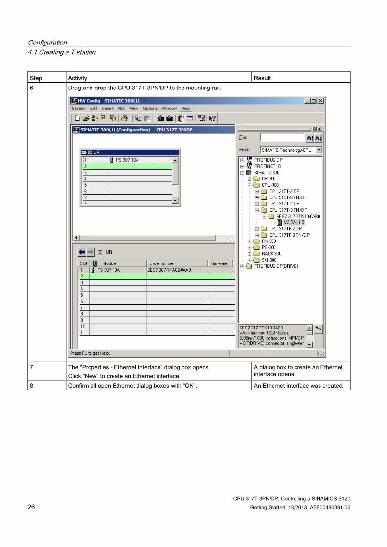
Step Activity Result 6 Drag-and-drop the CPU 317T-3PN/DP to the mounting rail.
7 The "Properties - Ethernet Interface" dialog box opens.
Click "New" to create an Ethernet interface. A dialog box to create an Ethernet interface opens.
8 Confirm all open Ethernet dialog boxes with "OK". An Ethernet interface was created.
Configuration 4.1 Creating a T station
CPU 317T-3PN/DP: Controlling a SINAMICS S120 Getting Started, 10/2013, A5E00480391-06 27
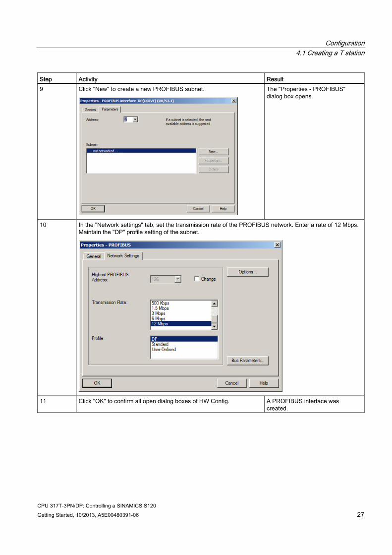
Step Activity Result 9 Click "New" to create a new PROFIBUS subnet.
The "Properties - PROFIBUS" dialog box opens.
10 In the "Network settings" tab, set the transmission rate of the PROFIBUS network. Enter a rate of 12 Mbps. Maintain the "DP" profile setting of the subnet.
11 Click "OK" to confirm all open dialog boxes of HW Config. A PROFIBUS interface was
created.
Configuration 4.1 Creating a T station
CPU 317T-3PN/DP: Controlling a SINAMICS S120 28 Getting Started, 10/2013, A5E00480391-06
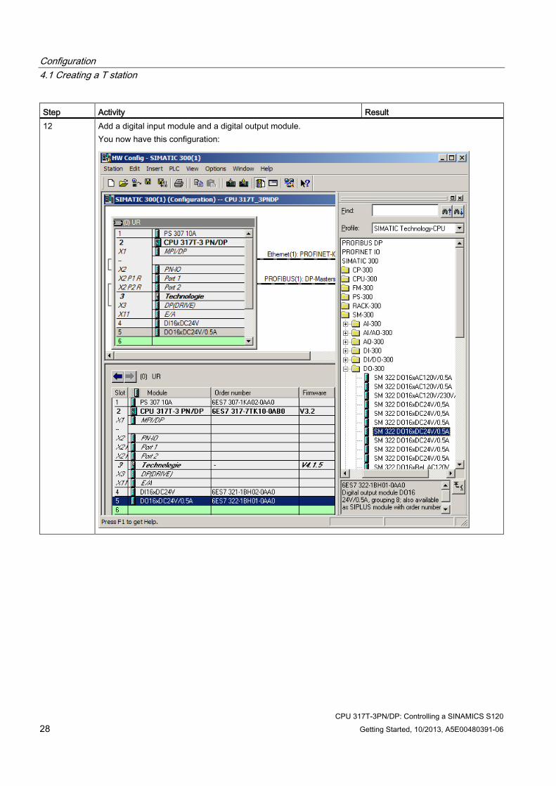
Step Activity Result 12 Add a digital input module and a digital output module.
You now have this configuration:
Configuration 4.1 Creating a T station
CPU 317T-3PN/DP: Controlling a SINAMICS S120 Getting Started, 10/2013, A5E00480391-06 29
4.1.2.2 Activating generation of the technology system data
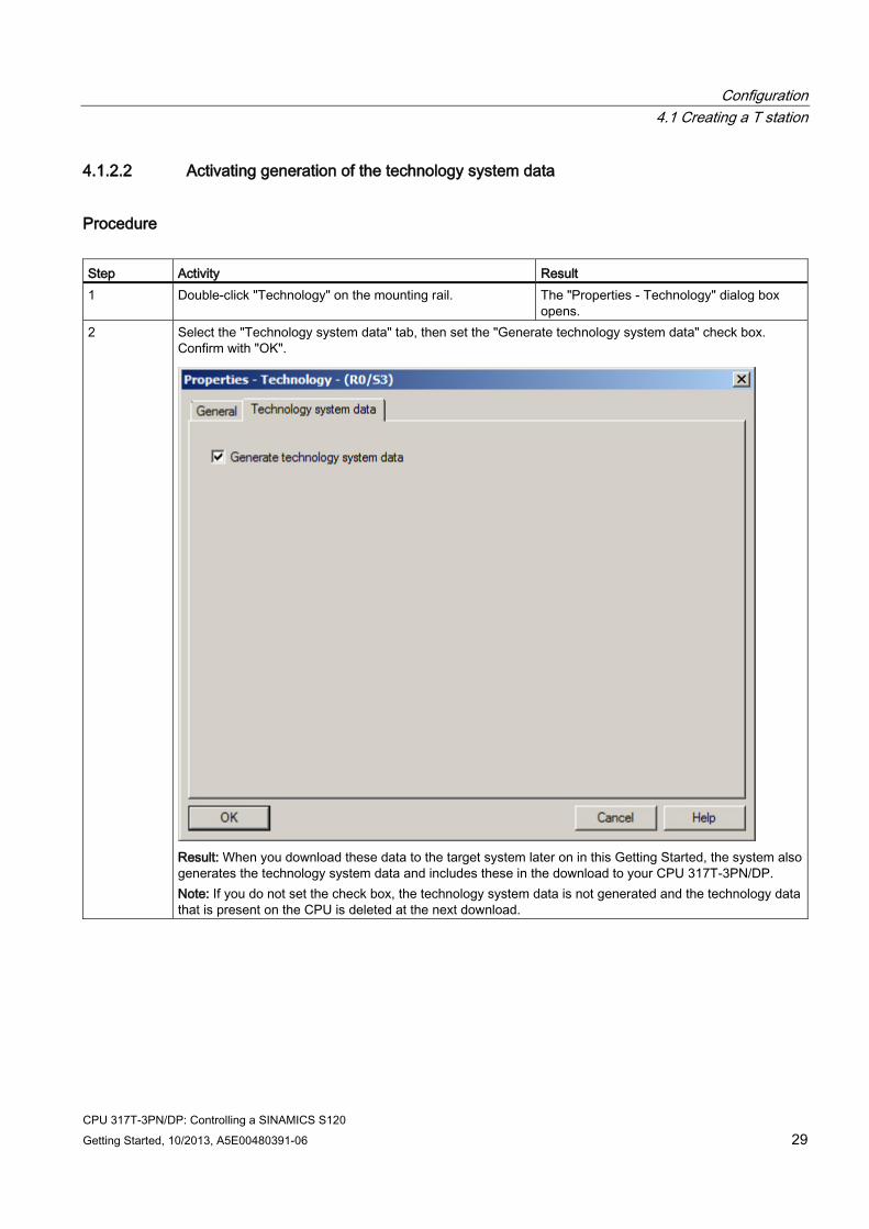
Procedure Step Activity Result 1 Double-click "Technology" on the mounting rail. The "Properties - Technology" dialog box
opens. 2 Select the "Technology system data" tab, then set the "Generate technology system data" check box.
Confirm with "OK".
Result: When you download these data to the target system later on in this Getting Started, the system also generates the technology system data and includes these in the download to your CPU 317T-3PN/DP. Note: If you do not set the check box, the technology system data is not generated and the technology data that is present on the CPU is deleted at the next download.
Configuration 4.1 Creating a T station
CPU 317T-3PN/DP: Controlling a SINAMICS S120 30 Getting Started, 10/2013, A5E00480391-06
4.1.2.3 Configuring a drive in HW Config
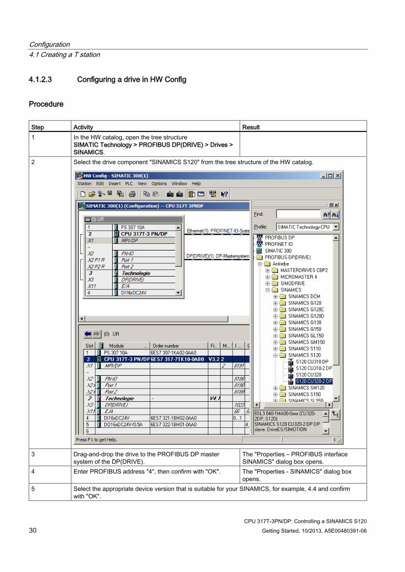
Procedure Step Activity Result 1 In the HW catalog, open the tree structure
SIMATIC Technology > PROFIBUS DP(DRIVE) > Drives > SINAMICS.
2 Select the drive component "SINAMICS S120" from the tree structure of the HW catalog.
3 Drag-and-drop the drive to the PROFIBUS DP master
system of the DP(DRIVE). The "Properties – PROFIBUS interface SINAMICS" dialog box opens.
4 Enter PROFIBUS address "4", then confirm with "OK". The "Properties - SINAMICS" dialog box opens.
5 Select the appropriate device version that is suitable for your SINAMICS, for example, 4.4 and confirm with "OK".
Configuration 4.1 Creating a T station
CPU 317T-3PN/DP: Controlling a SINAMICS S120 Getting Started, 10/2013, A5E00480391-06 31
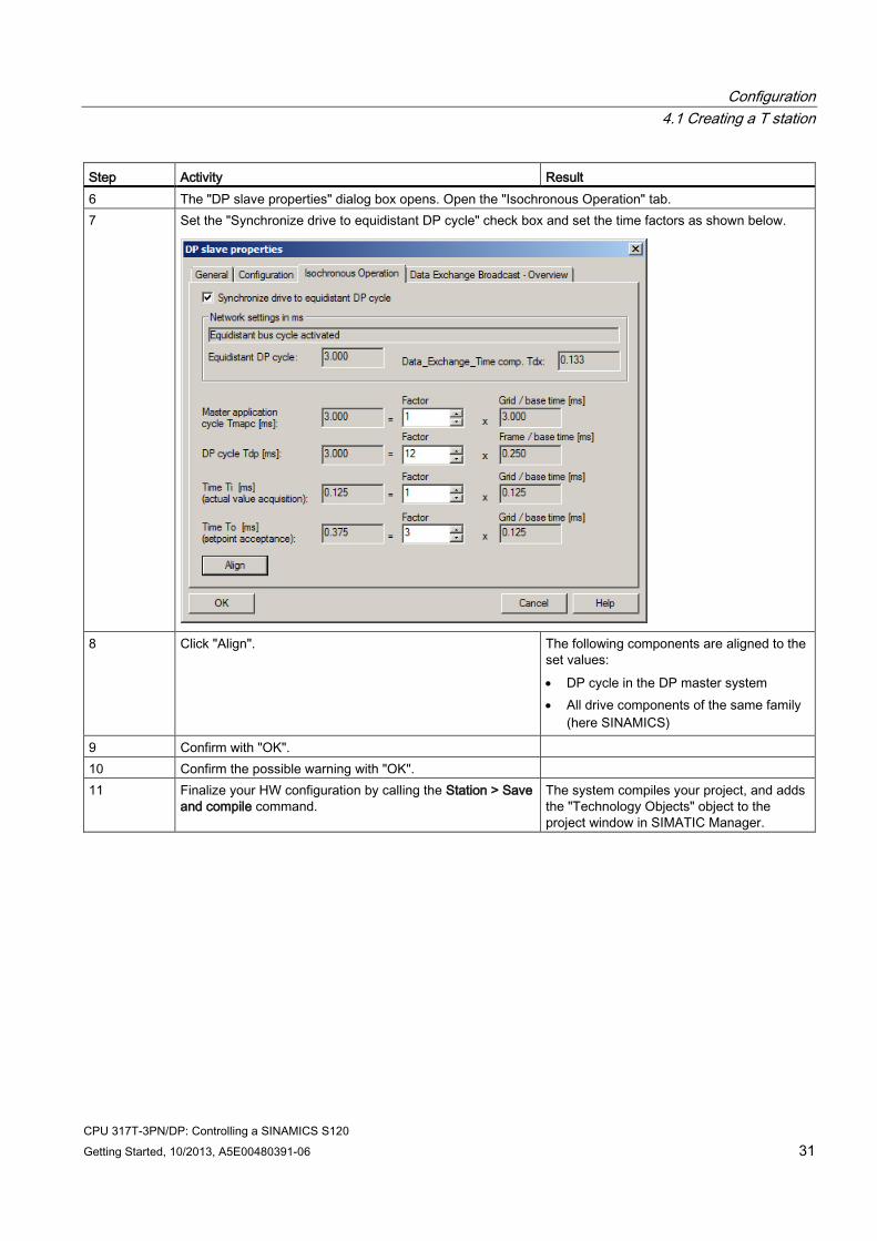
Step Activity Result 6 The "DP slave properties" dialog box opens. Open the "Isochronous Operation" tab. 7 Set the "Synchronize drive to equidistant DP cycle" check box and set the time factors as shown below.
8 Click "Align". The following components are aligned to the
set values: • DP cycle in the DP master system • All drive components of the same family
(here SINAMICS)
9 Confirm with "OK". 10 Confirm the possible warning with "OK". 11 Finalize your HW configuration by calling the Station > Save
and compile command. The system compiles your project, and adds the "Technology Objects" object to the project window in SIMATIC Manager.
Configuration 4.1 Creating a T station
CPU 317T-3PN/DP: Controlling a SINAMICS S120 32 Getting Started, 10/2013, A5E00480391-06
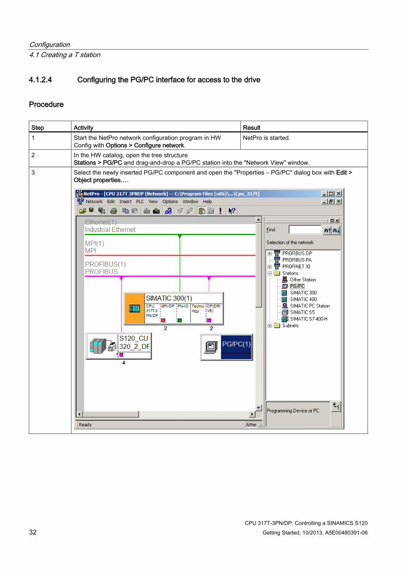
4.1.2.4 Configuring the PG/PC interface for access to the drive
Procedure Step Activity Result 1 Start the NetPro network configuration program in HW
Config with Options > Configure network. NetPro is started.
2 In the HW catalog, open the tree structure Stations > PG/PC and drag-and-drop a PG/PC station into the "Network View" window.
3 Select the newly inserted PG/PC component and open the "Properties – PG/PC" dialog box with Edit > Object properties….
Configuration 4.1 Creating a T station
CPU 317T-3PN/DP: Controlling a SINAMICS S120 Getting Started, 10/2013, A5E00480391-06 33
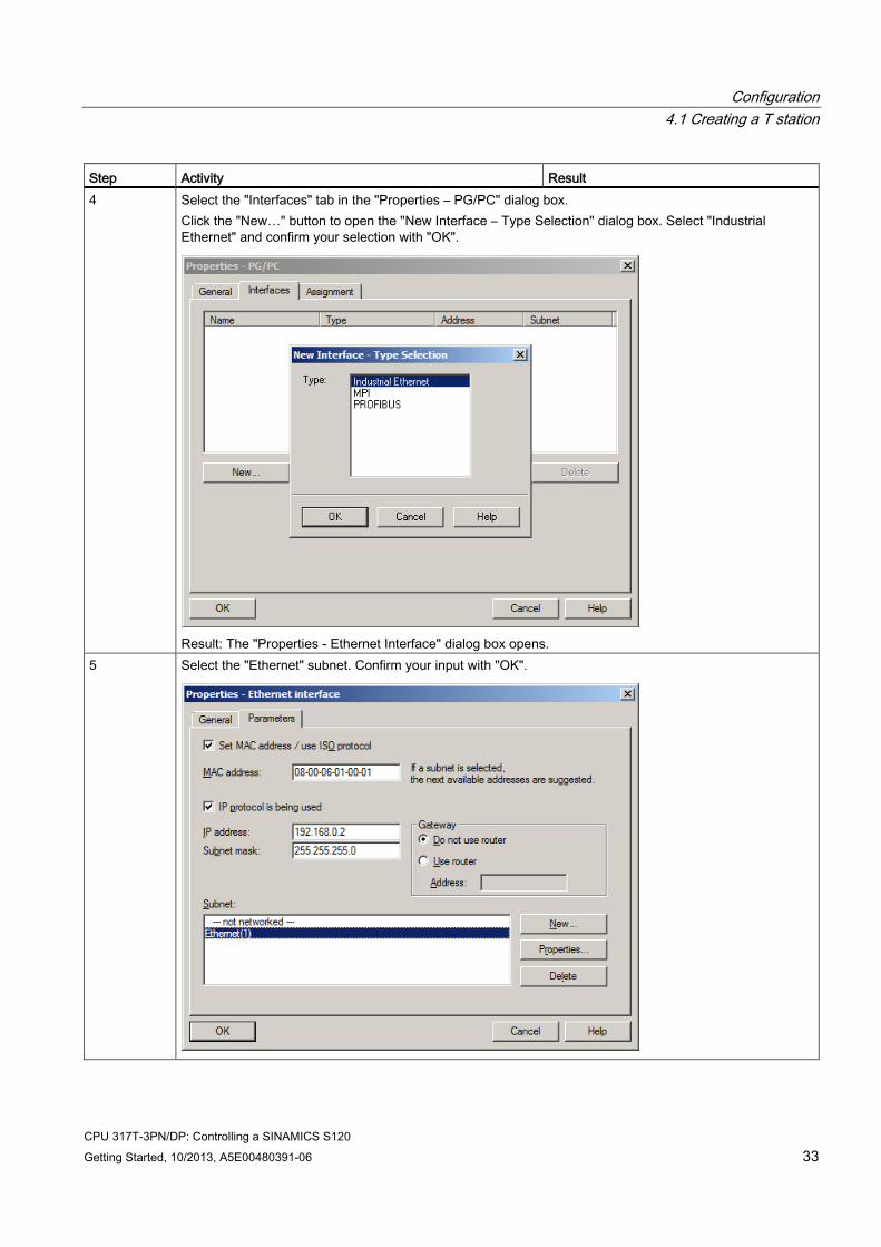
Step Activity Result 4 Select the "Interfaces" tab in the "Properties – PG/PC" dialog box.
Click the "New…" button to open the "New Interface – Type Selection" dialog box. Select "Industrial Ethernet" and confirm your selection with "OK".
Result: The "Properties - Ethernet Interface" dialog box opens.
5 Select the "Ethernet" subnet. Confirm your input with "OK".
Configuration 4.1 Creating a T station
CPU 317T-3PN/DP: Controlling a SINAMICS S120 34 Getting Started, 10/2013, A5E00480391-06
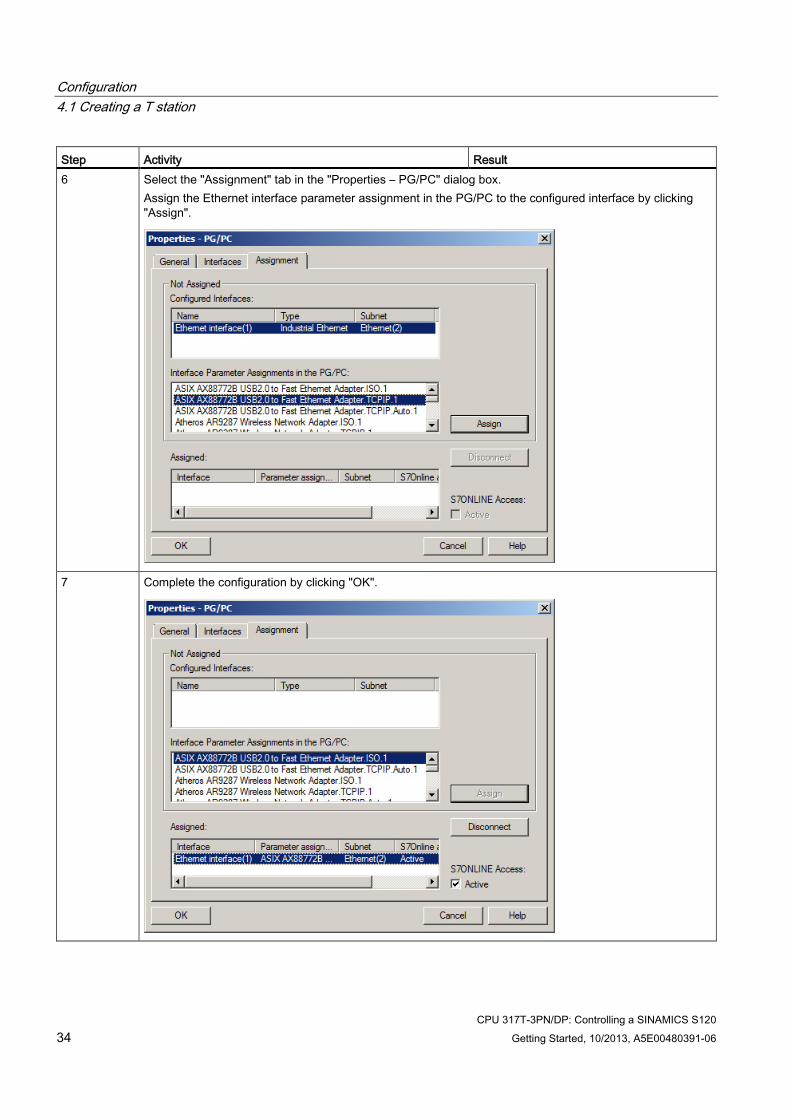
Step Activity Result 6 Select the "Assignment" tab in the "Properties – PG/PC" dialog box.
Assign the Ethernet interface parameter assignment in the PG/PC to the configured interface by clicking "Assign".
7 Complete the configuration by clicking "OK".
Configuration 4.1 Creating a T station
CPU 317T-3PN/DP: Controlling a SINAMICS S120 Getting Started, 10/2013, A5E00480391-06 35
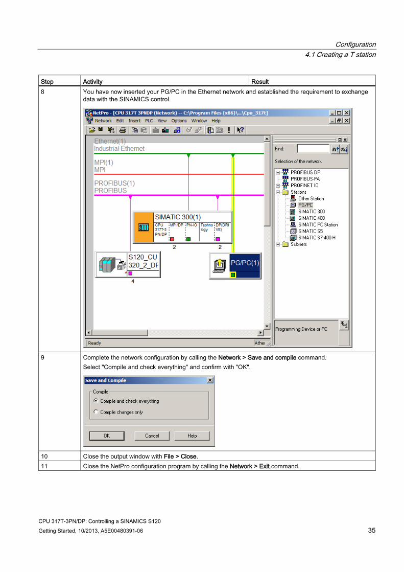
Step Activity Result 8 You have now inserted your PG/PC in the Ethernet network and established the requirement to exchange
data with the SINAMICS control.
9 Complete the network configuration by calling the Network > Save and compile command.
Select "Compile and check everything" and confirm with "OK".
10 Close the output window with File > Close. 11 Close the NetPro configuration program by calling the Network > Exit command.
Configuration 4.2 Downloading the hardware configuration to the target hardware
CPU 317T-3PN/DP: Controlling a SINAMICS S120 36 Getting Started, 10/2013, A5E00480391-06
4.2 Downloading the hardware configuration to the target hardware
Procedure Step Activity 1 Switch back to HW Config.
Download the hardware configuration to the CPU using the menu command PLC > Download to Module. 2 Exit HW Config with Station > Exit.
Configuration 4.3 Configuring a SINAMICS drive in S7T Config
CPU 317T-3PN/DP: Controlling a SINAMICS S120 Getting Started, 10/2013, A5E00480391-06 37
4.3 Configuring a SINAMICS drive in S7T Config
Basic procedure 1. Automatic online configuration of the drives
2. Offline configuration of the Servo 03 drive without complete DRIVE-CLIQ technology
3. Offline configuration of the Servo 02 drive with complete DRIVE-CLIQ technology
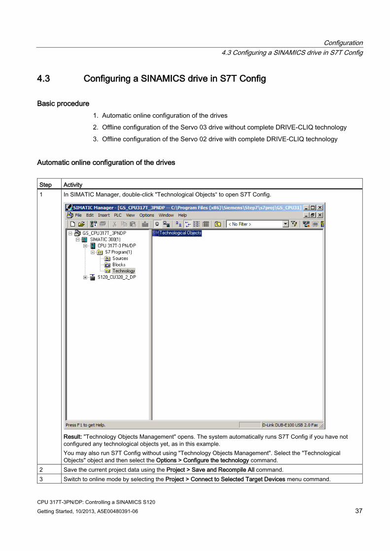
Automatic online configuration of the drives Step Activity 1 In SIMATIC Manager, double-click "Technological Objects“ to open S7T Config.
Result: "Technology Objects Management" opens. The system automatically runs S7T Config if you have not configured any technological objects yet, as in this example. You may also run S7T Config without using "Technology Objects Management". Select the "Technological Objects" object and then select the Options > Configure the technology command.
2 Save the current project data using the Project > Save and Recompile All command. 3 Switch to online mode by selecting the Project > Connect to Selected Target Devices menu command.
Configuration 4.3 Configuring a SINAMICS drive in S7T Config
CPU 317T-3PN/DP: Controlling a SINAMICS S120 38 Getting Started, 10/2013, A5E00480391-06
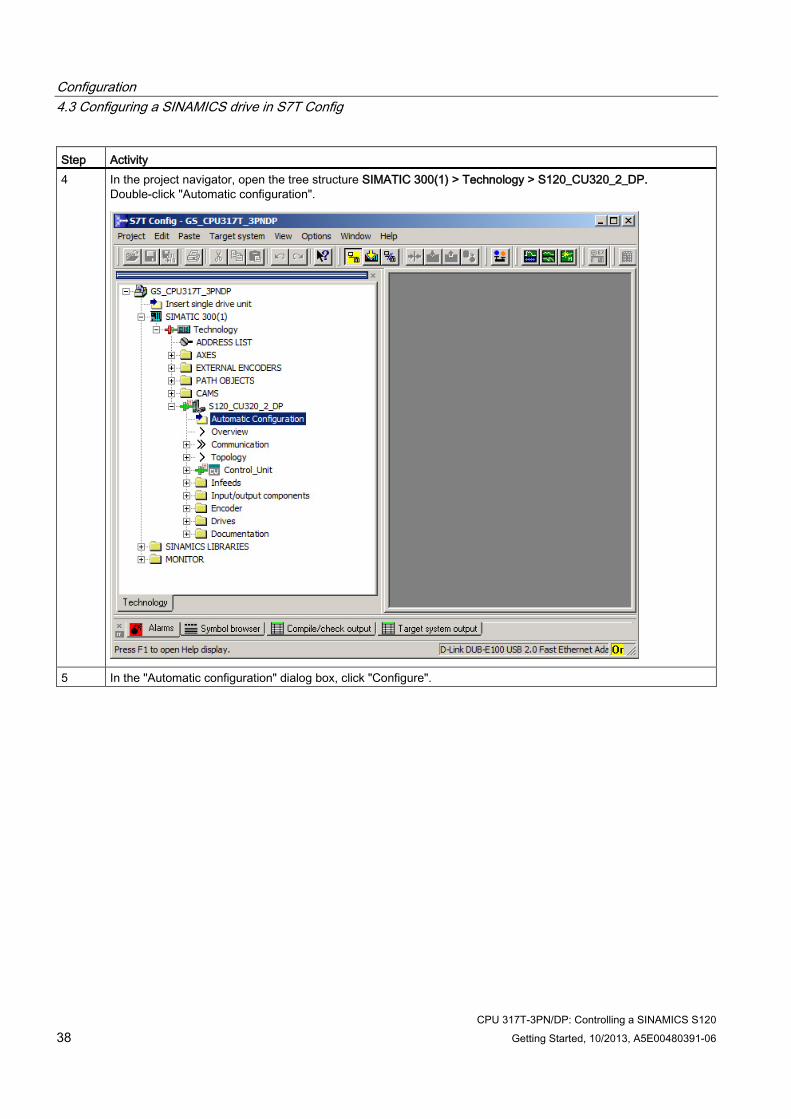
Step Activity 4 In the project navigator, open the tree structure SIMATIC 300(1) > Technology > S120_CU320_2_DP.
Double-click "Automatic configuration".
5 In the "Automatic configuration" dialog box, click "Configure".
Configuration 4.3 Configuring a SINAMICS drive in S7T Config
CPU 317T-3PN/DP: Controlling a SINAMICS S120 Getting Started, 10/2013, A5E00480391-06 39
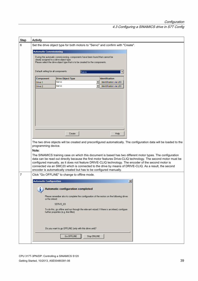
Step Activity 6 Set the drive object type for both motors to "Servo" and confirm with "Create".
The two drive objects will be created and preconfigured automatically. The configuration data will be loaded to the programming device. Note: The SINAMICS training case on which this document is based has two different motor types. The configuration data can be read out directly because the first motor features Drive-CLIQ technology. The second motor must be configured manually, as it does not feature DRIVE-CLIQ technology. The encoder of the second motor is connected via an SMC20 which is connected to the drive by means of DRIVE-CLIQ. As a result, the second encoder is automatically created but has to be configured manually.
7 Click "Go OFFLINE" to change to offline mode.
Configuration 4.3 Configuring a SINAMICS drive in S7T Config
CPU 317T-3PN/DP: Controlling a SINAMICS S120 40 Getting Started, 10/2013, A5E00480391-06
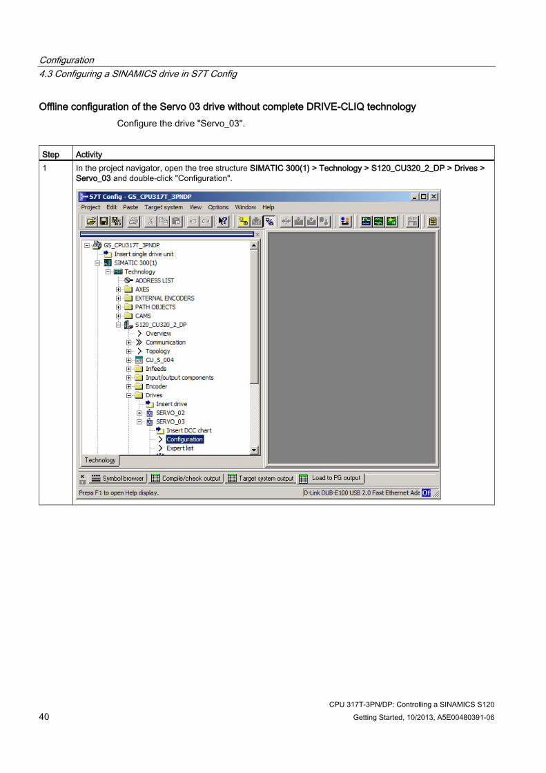
Offline configuration of the Servo 03 drive without complete DRIVE-CLIQ technology Configure the drive "Servo_03".
Step Activity 1 In the project navigator, open the tree structure SIMATIC 300(1) > Technology > S120_CU320_2_DP > Drives >
Servo_03 and double-click "Configuration".
Configuration 4.3 Configuring a SINAMICS drive in S7T Config
CPU 317T-3PN/DP: Controlling a SINAMICS S120 Getting Started, 10/2013, A5E00480391-06 41
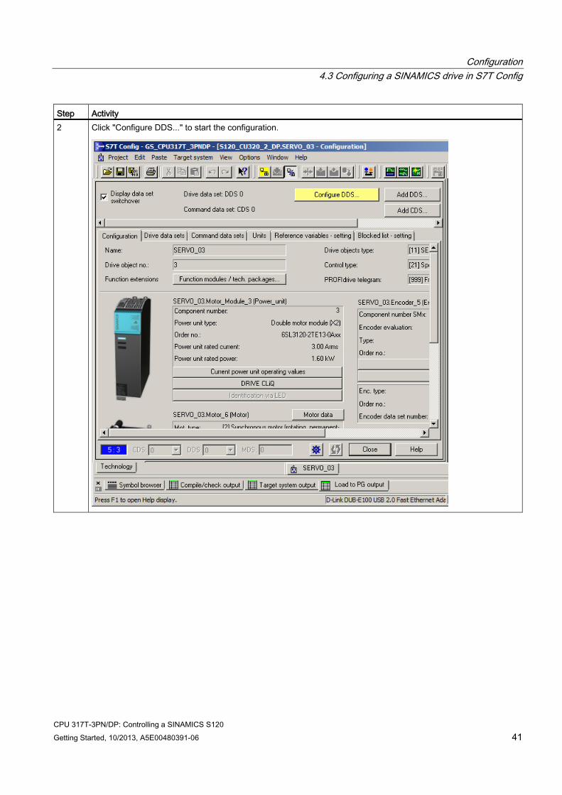
Step Activity 2 Click "Configure DDS..." to start the configuration.
Configuration 4.3 Configuring a SINAMICS drive in S7T Config
CPU 317T-3PN/DP: Controlling a SINAMICS S120 42 Getting Started, 10/2013, A5E00480391-06
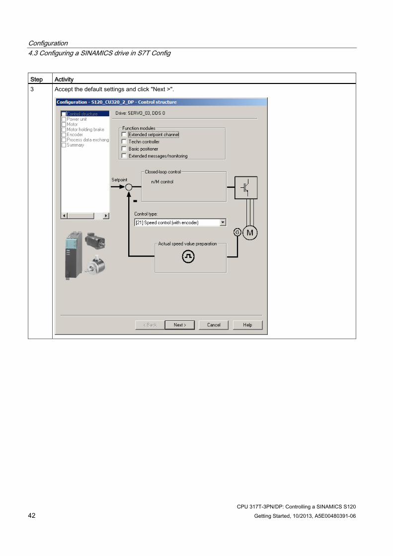
Step Activity 3 Accept the default settings and click "Next >".
Configuration 4.3 Configuring a SINAMICS drive in S7T Config
CPU 317T-3PN/DP: Controlling a SINAMICS S120 Getting Started, 10/2013, A5E00480391-06 43
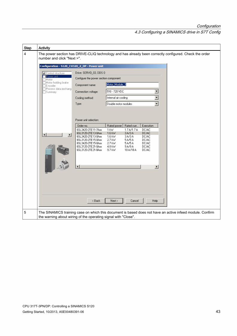
Step Activity 4 The power section has DRIVE-CLIQ technology and has already been correctly configured. Check the order
number and click "Next >".
5 The SINAMICS training case on which this document is based does not have an active infeed module. Confirm
the warning about wiring of the operating signal with "Close".
Configuration 4.3 Configuring a SINAMICS drive in S7T Config
CPU 317T-3PN/DP: Controlling a SINAMICS S120 44 Getting Started, 10/2013, A5E00480391-06
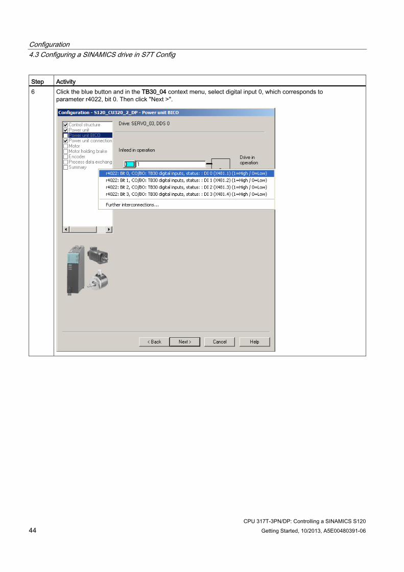
Step Activity 6 Click the blue button and in the TB30_04 context menu, select digital input 0, which corresponds to
parameter r4022, bit 0. Then click "Next >".
Configuration 4.3 Configuring a SINAMICS drive in S7T Config
CPU 317T-3PN/DP: Controlling a SINAMICS S120 Getting Started, 10/2013, A5E00480391-06 45
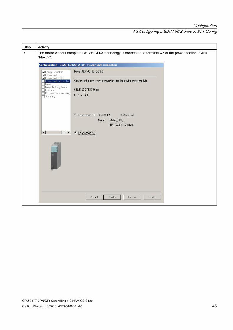
Step Activity 7 The motor without complete DRIVE-CLIQ technology is connected to terminal X2 of the power section. ‘Click
"Next >".
Configuration 4.3 Configuring a SINAMICS drive in S7T Config
CPU 317T-3PN/DP: Controlling a SINAMICS S120 46 Getting Started, 10/2013, A5E00480391-06
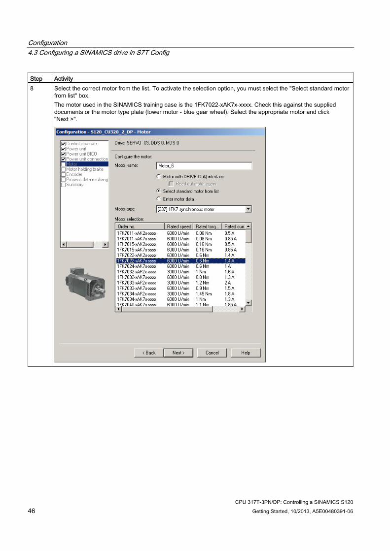
Step Activity 8 Select the correct motor from the list. To activate the selection option, you must select the "Select standard motor
from list" box. The motor used in the SINAMICS training case is the 1FK7022-xAK7x-xxxx. Check this against the supplied documents or the motor type plate (lower motor - blue gear wheel). Select the appropriate motor and click "Next >".
Configuration 4.3 Configuring a SINAMICS drive in S7T Config
CPU 317T-3PN/DP: Controlling a SINAMICS S120 Getting Started, 10/2013, A5E00480391-06 47
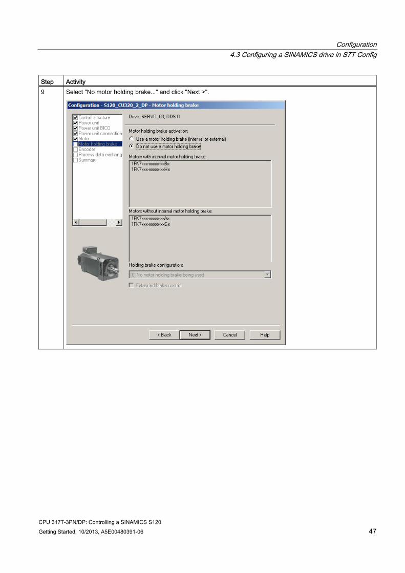
Step Activity 9 Select "No motor holding brake..." and click "Next >".
Configuration 4.3 Configuring a SINAMICS drive in S7T Config
CPU 317T-3PN/DP: Controlling a SINAMICS S120 48 Getting Started, 10/2013, A5E00480391-06
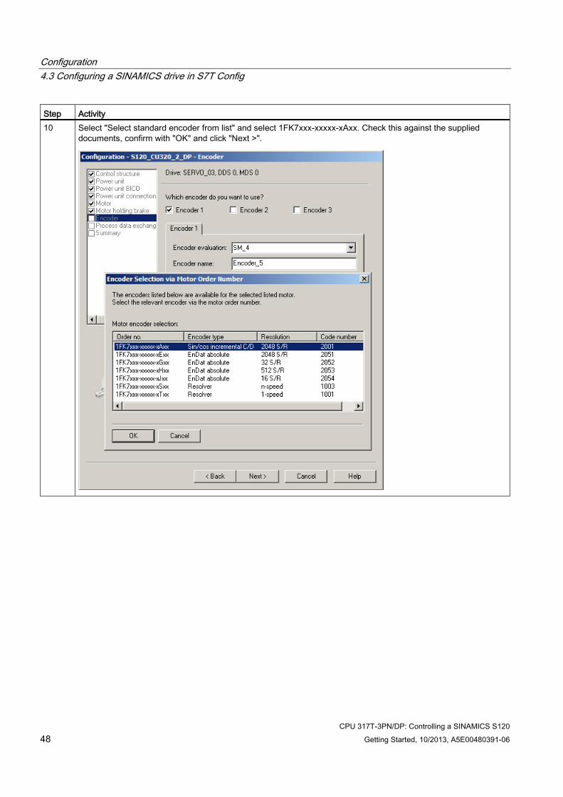
Step Activity 10 Select "Select standard encoder from list" and select 1FK7xxx-xxxxx-xAxx. Check this against the supplied
documents, confirm with "OK" and click "Next >".
Configuration 4.3 Configuring a SINAMICS drive in S7T Config
CPU 317T-3PN/DP: Controlling a SINAMICS S120 Getting Started, 10/2013, A5E00480391-06 49
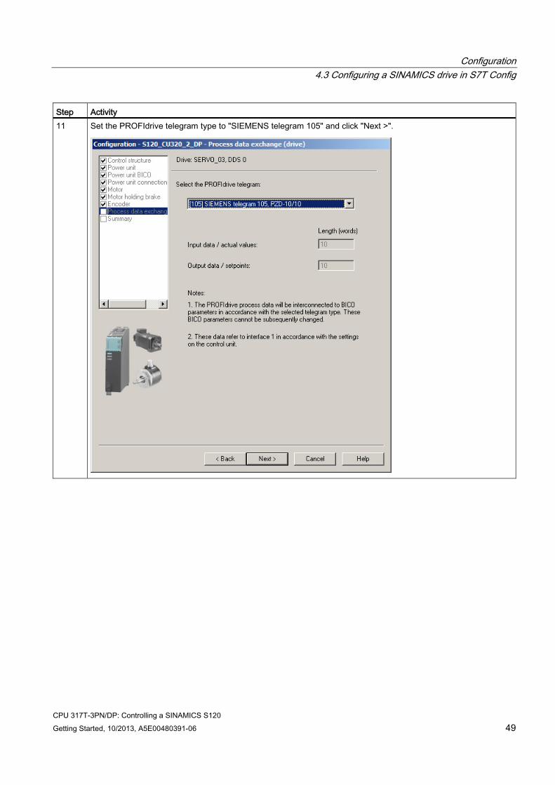
Step Activity 11 Set the PROFIdrive telegram type to "SIEMENS telegram 105" and click "Next >".
Configuration 4.3 Configuring a SINAMICS drive in S7T Config
CPU 317T-3PN/DP: Controlling a SINAMICS S120 50 Getting Started, 10/2013, A5E00480391-06
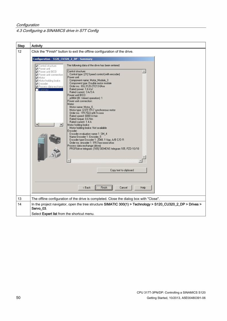
Step Activity 12 Click the "Finish" button to exit the offline configuration of the drive.
13 The offline configuration of the drive is completed. Close the dialog box with "Close". 14 In the project navigator, open the tree structure SIMATIC 300(1) > Technology > S120_CU320_2_DP > Drives >
Servo_03. Select Expert list from the shortcut menu.
Configuration 4.3 Configuring a SINAMICS drive in S7T Config
CPU 317T-3PN/DP: Controlling a SINAMICS S120 Getting Started, 10/2013, A5E00480391-06 51
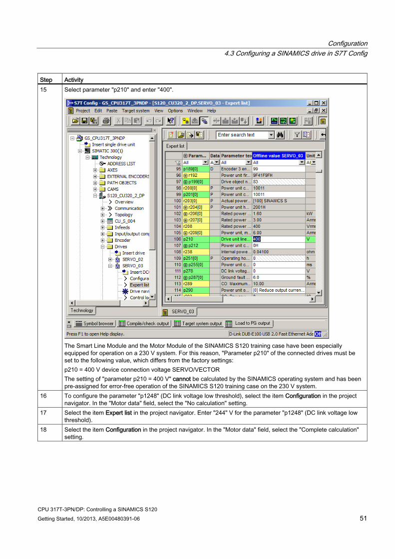
Step Activity 15 Select parameter "p210" and enter "400".
The Smart Line Module and the Motor Module of the SINAMICS S120 training case have been especially equipped for operation on a 230 V system. For this reason, "Parameter p210" of the connected drives must be set to the following value, which differs from the factory settings: p210 = 400 V device connection voltage SERVO/VECTOR The setting of "parameter p210 = 400 V" cannot be calculated by the SINAMICS operating system and has been pre-assigned for error-free operation of the SINAMICS S120 training case on the 230 V system.
16 To configure the parameter "p1248" (DC link voltage low threshold), select the item Configuration in the project navigator. In the "Motor data" field, select the "No calculation" setting.
17 Select the item Expert list in the project navigator. Enter "244" V for the parameter "p1248" (DC link voltage low threshold).
18 Select the item Configuration in the project navigator. In the "Motor data" field, select the "Complete calculation" setting.
Configuration 4.3 Configuring a SINAMICS drive in S7T Config
CPU 317T-3PN/DP: Controlling a SINAMICS S120 52 Getting Started, 10/2013, A5E00480391-06
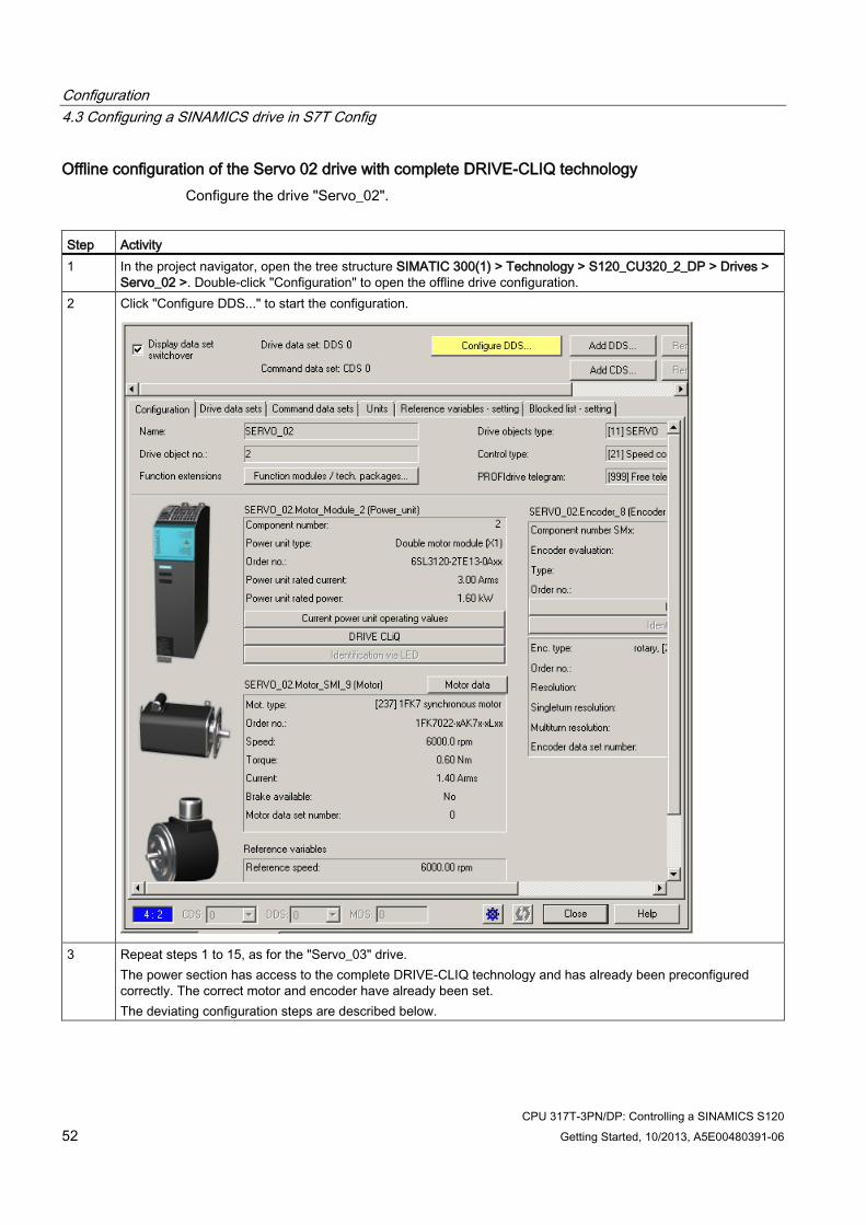
Offline configuration of the Servo 02 drive with complete DRIVE-CLIQ technology Configure the drive "Servo_02".
Step Activity 1 In the project navigator, open the tree structure SIMATIC 300(1) > Technology > S120_CU320_2_DP > Drives >
Servo_02 >. Double-click "Configuration" to open the offline drive configuration. 2 Click "Configure DDS..." to start the configuration.
3 Repeat steps 1 to 15, as for the "Servo_03" drive.
The power section has access to the complete DRIVE-CLIQ technology and has already been preconfigured correctly. The correct motor and encoder have already been set. The deviating configuration steps are described below.
Configuration 4.3 Configuring a SINAMICS drive in S7T Config
CPU 317T-3PN/DP: Controlling a SINAMICS S120 Getting Started, 10/2013, A5E00480391-06 53
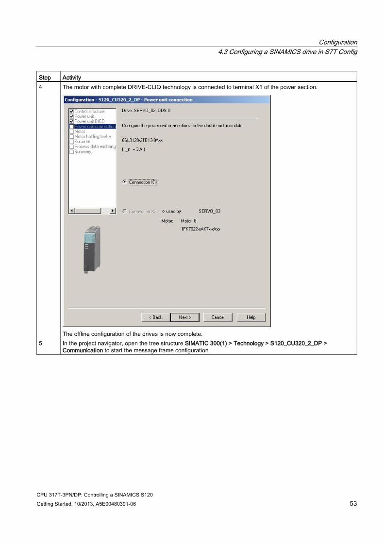
Step Activity 4
The motor with complete DRIVE-CLIQ technology is connected to terminal X1 of the power section.
The offline configuration of the drives is now complete.
5 In the project navigator, open the tree structure SIMATIC 300(1) > Technology > S120_CU320_2_DP > Communication to start the message frame configuration.
Configuration 4.3 Configuring a SINAMICS drive in S7T Config
CPU 317T-3PN/DP: Controlling a SINAMICS S120 54 Getting Started, 10/2013, A5E00480391-06
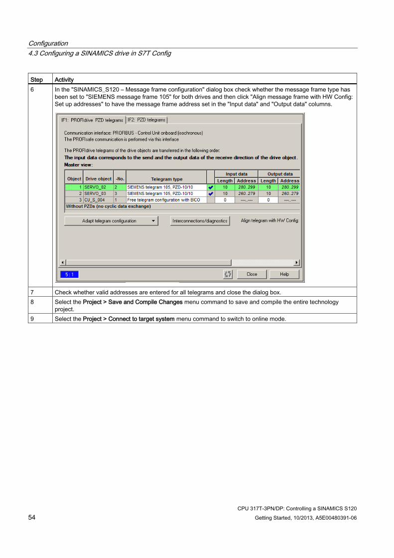
Step Activity 6 In the "SINAMICS_S120 – Message frame configuration" dialog box check whether the message frame type has
been set to "SIEMENS message frame 105" for both drives and then click "Align message frame with HW Config: Set up addresses" to have the message frame address set in the "Input data" and "Output data" columns.
7 Check whether valid addresses are entered for all telegrams and close the dialog box. 8 Select the Project > Save and Compile Changes menu command to save and compile the entire technology
project. 9 Select the Project > Connect to target system menu command to switch to online mode.
Configuration 4.3 Configuring a SINAMICS drive in S7T Config
CPU 317T-3PN/DP: Controlling a SINAMICS S120 Getting Started, 10/2013, A5E00480391-06 55
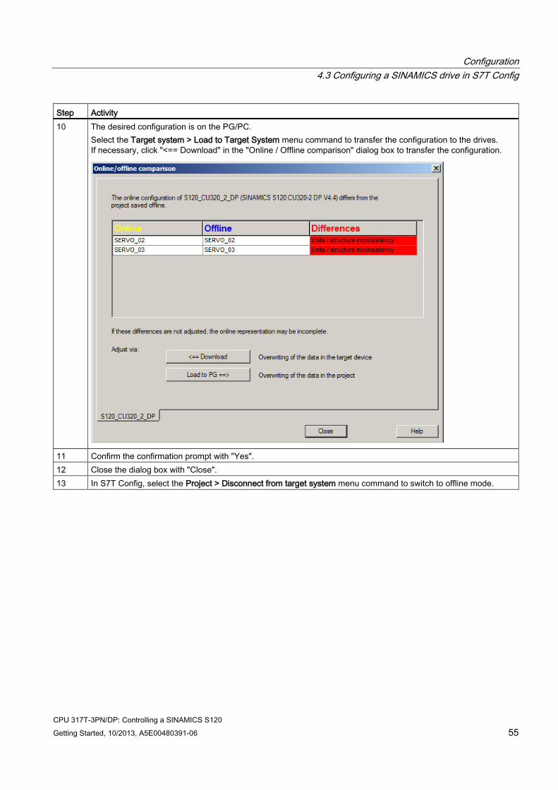
Step Activity 10 The desired configuration is on the PG/PC.
Select the Target system > Load to Target System menu command to transfer the configuration to the drives. If necessary, click "<== Download" in the "Online / Offline comparison" dialog box to transfer the configuration.
11 Confirm the confirmation prompt with "Yes". 12 Close the dialog box with "Close". 13 In S7T Config, select the Project > Disconnect from target system menu command to switch to offline mode.
Configuration 4.4 Configuring axes in S7T Config
CPU 317T-3PN/DP: Controlling a SINAMICS S120 56 Getting Started, 10/2013, A5E00480391-06
4.4 Configuring axes in S7T Config
Important information In this step, you create your technology objects (e.g., axes) with S7T Config. Use "Technology Objects Management“ to generate a technology DB for each TO. Do not copy the technology DBs in order to ensure a defined assignment between the technology DB and its TO.
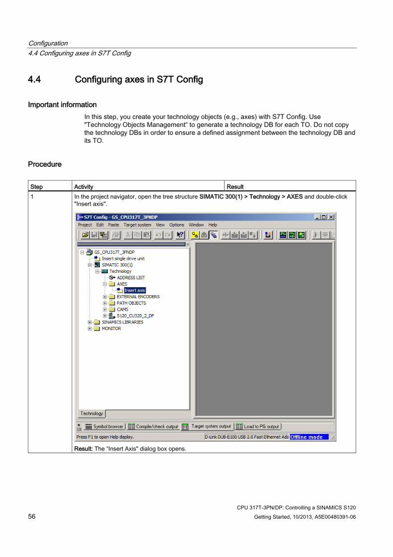
Procedure Step Activity Result 1 In the project navigator, open the tree structure SIMATIC 300(1) > Technology > AXES and double-click
"Insert axis".
Result: The “Insert Axis" dialog box opens.
Configuration 4.4 Configuring axes in S7T Config
CPU 317T-3PN/DP: Controlling a SINAMICS S120 Getting Started, 10/2013, A5E00480391-06 57
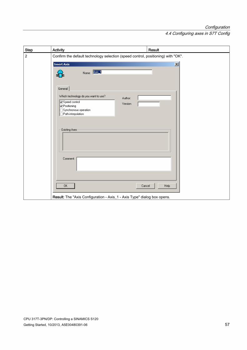
Step Activity Result 2 Confirm the default technology selection (speed control, positioning) with "OK".
Result: The "Axis Configuration - Axis_1 - Axis Type" dialog box opens.
Configuration 4.4 Configuring axes in S7T Config
CPU 317T-3PN/DP: Controlling a SINAMICS S120 58 Getting Started, 10/2013, A5E00480391-06
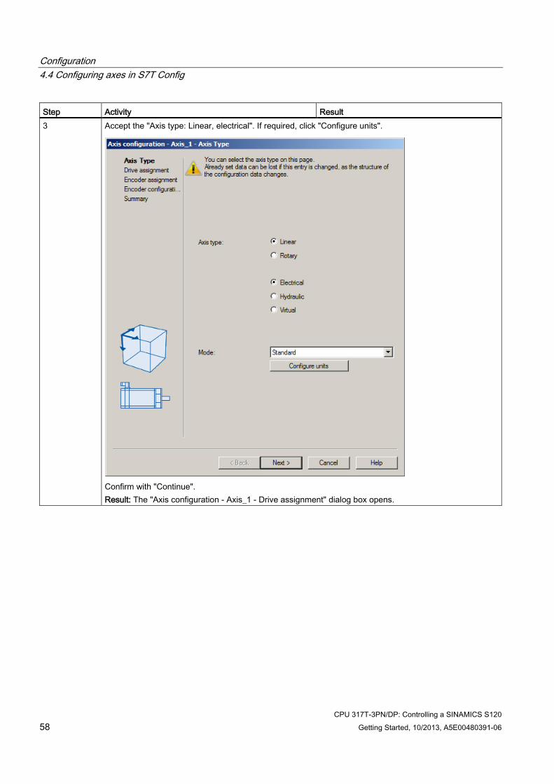
Step Activity Result 3 Accept the "Axis type: Linear, electrical". If required, click "Configure units".
Confirm with "Continue". Result: The "Axis configuration - Axis_1 - Drive assignment" dialog box opens.
Configuration 4.4 Configuring axes in S7T Config
CPU 317T-3PN/DP: Controlling a SINAMICS S120 Getting Started, 10/2013, A5E00480391-06 59
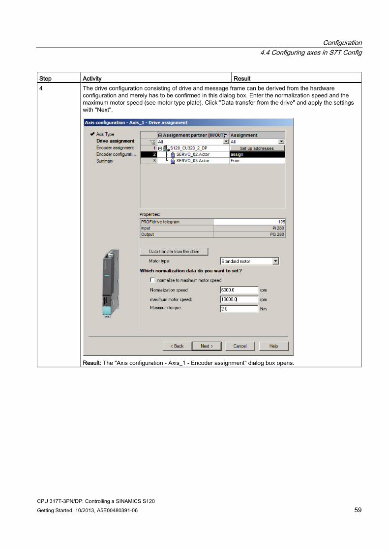
Step Activity Result 4 The drive configuration consisting of drive and message frame can be derived from the hardware
configuration and merely has to be confirmed in this dialog box. Enter the normalization speed and the maximum motor speed (see motor type plate). Click "Data transfer from the drive" and apply the settings with "Next".
Result: The "Axis configuration - Axis_1 - Encoder assignment" dialog box opens.
Configuration 4.4 Configuring axes in S7T Config
CPU 317T-3PN/DP: Controlling a SINAMICS S120 60 Getting Started, 10/2013, A5E00480391-06
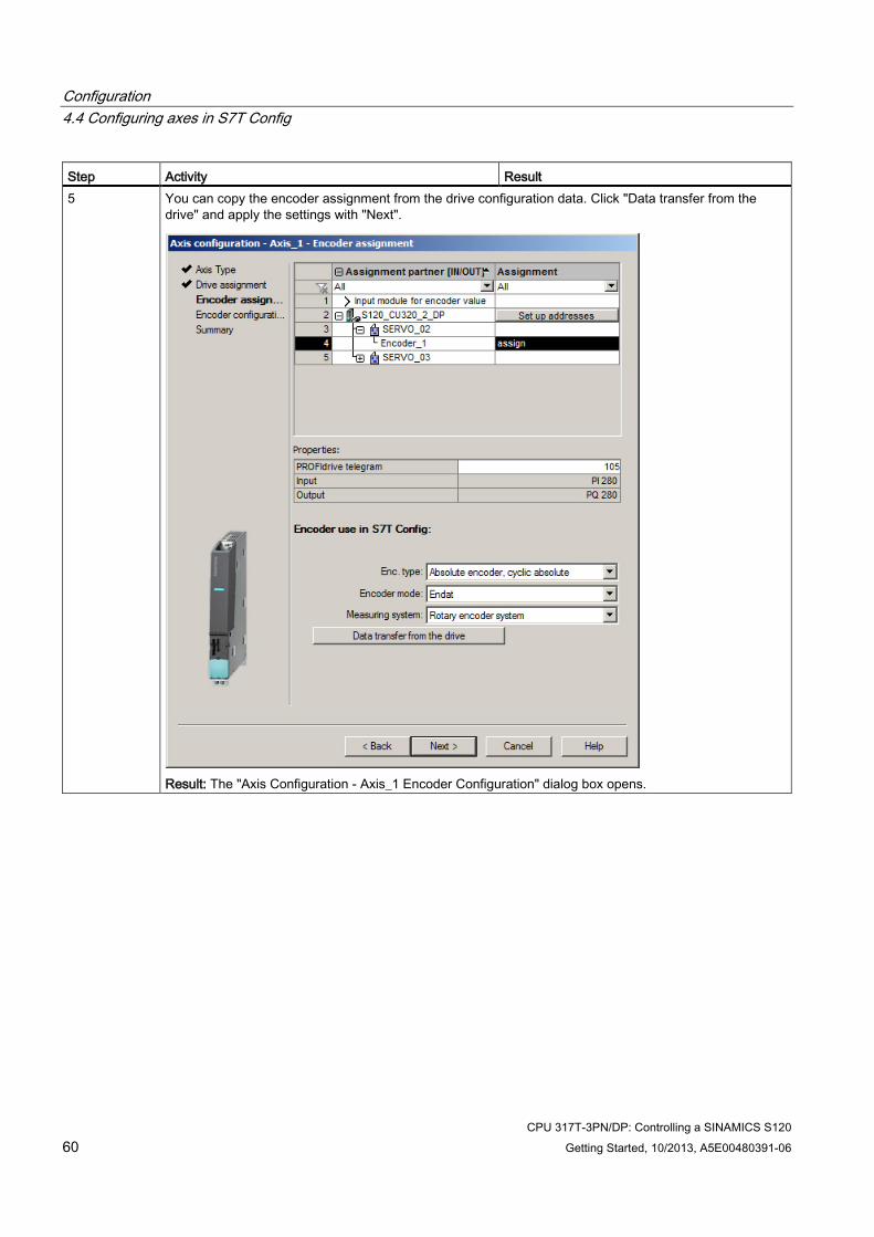
Step Activity Result 5 You can copy the encoder assignment from the drive configuration data. Click "Data transfer from the
drive" and apply the settings with "Next".
Result: The "Axis Configuration - Axis_1 Encoder Configuration" dialog box opens.
Configuration 4.4 Configuring axes in S7T Config
CPU 317T-3PN/DP: Controlling a SINAMICS S120 Getting Started, 10/2013, A5E00480391-06 61
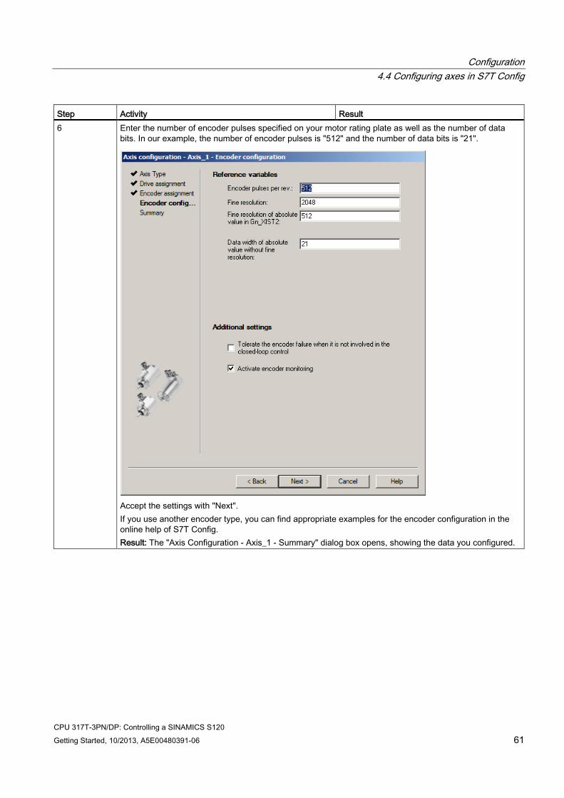
Step Activity Result 6 Enter the number of encoder pulses specified on your motor rating plate as well as the number of data
bits. In our example, the number of encoder pulses is "512" and the number of data bits is "21".
Accept the settings with "Next". If you use another encoder type, you can find appropriate examples for the encoder configuration in the online help of S7T Config. Result: The "Axis Configuration - Axis_1 - Summary" dialog box opens, showing the data you configured.
Configuration 4.4 Configuring axes in S7T Config
CPU 317T-3PN/DP: Controlling a SINAMICS S120 62 Getting Started, 10/2013, A5E00480391-06
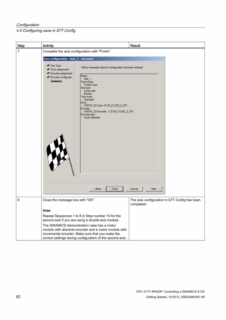
Step Activity Result 7 Complete the axis configuration with "Finish".
8
Close the message box with "OK". Note: Repeat Sequences 1 to 8 in Step number 10 for the second axis if you are using a double-axis module. The SINAMICS demonstration case has a motor module with absolute encoder and a motor module with incremental encoder. Make sure that you make the correct settings during configuration of the second axis.
The axis configuration in S7T Config has been completed.
Configuration 4.4 Configuring axes in S7T Config
CPU 317T-3PN/DP: Controlling a SINAMICS S120 Getting Started, 10/2013, A5E00480391-06 63
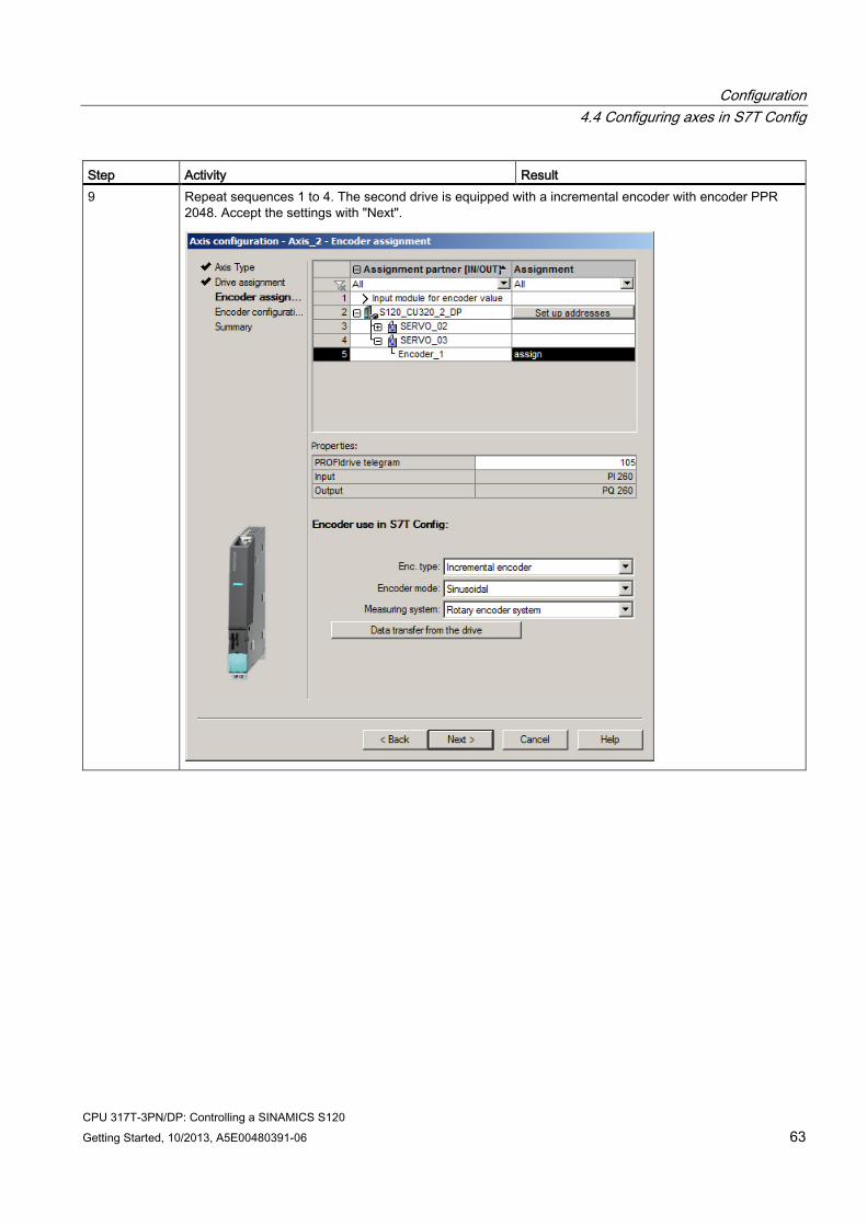
Step Activity Result 9 Repeat sequences 1 to 4. The second drive is equipped with a incremental encoder with encoder PPR
2048. Accept the settings with "Next".
Configuration 4.4 Configuring axes in S7T Config
CPU 317T-3PN/DP: Controlling a SINAMICS S120 64 Getting Started, 10/2013, A5E00480391-06
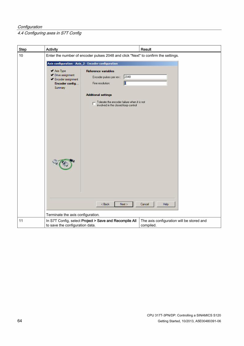
Step Activity Result 10 Enter the number of encoder pulses 2048 and click "Next" to confirm the settings.
Terminate the axis configuration.
11 In S7T Config, select Project > Save and Recompile All to save the configuration data.
The axis configuration will be stored and compiled.
Programming
CPU 317T-3PN/DP: Controlling a SINAMICS S120 Getting Started, 10/2013, A5E00480391-06 65
Programming 5 5.1 Creating technology data blocks
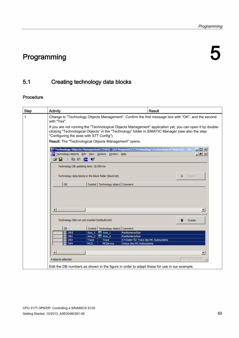
Procedure Step Activity Result 1 Change to "Technology Objects Management". Confirm the first message box with "OK", and the second
with "Yes". If you are not running the "Technological Objects Management“ application yet, you can open it by double-clicking "Technological Objects“ in the "Technology“ folder in SIMATIC Manager (see also the step: "Configuring the axes with S7T Config"). Result: The "Technological Objects Management" opens.
Edit the DB numbers as shown in the figure in order to adapt these for use in our example.
Programming 5.2 Controlling the axis with the STEP 7 user program using a sample project
CPU 317T-3PN/DP: Controlling a SINAMICS S120 66 Getting Started, 10/2013, A5E00480391-06
Step Activity Result 2 Create the technology DBs listed below by clicking "Create":
• Axis_1 • Axis_2 (if this exists) • Trace • MCDevice
The system generates the technology data blocks DB 1 to DB 3, or DB 4.
3 Close the "Technology Objects Management" by selecting the Technological objects > Exit menu command.
5.2 Controlling the axis with the STEP 7 user program using a sample project
The sample project "PROJECT-CPU317T" is used to describe the procedure. The sample project is included in the S7 Technology installation package.
Procedure Step Activity Result 1 In SIMATIC Manager, open the sample project "PROJECT-
CPU317T". Copy the blocks listed below to your project: • OB1 • FB 100 (SimplePositioning) • FB401 (MC_Power) • FB402 (MC_Power) • FB405 (MC_Halt) • FB410 (MC_MoveAbsolute) • DB 100 (IDB_SimplePositioning) • AxisData (variable table for axis control) Confirm the message "The object 'OB1' already exists. Do you want to overwrite it?” with "Yes". Also copy the inputs (I), outputs (O) and flags (F) from the example symbol table to the project, so that the symbols are displayed completely in the variable table. Important: The sample program does not contain DB 1 to DB 4! Create these technology DBs in STEP 7 (see the step "Creating the technology DBs"), in order to maintain consistency between the user program and the technology objects.
The sample program is copied to the project.
2 Double-click the FB 100 if you want to edit the program example.
The LAD/STL/FBD editor opens.
Programming 5.2 Controlling the axis with the STEP 7 user program using a sample project
CPU 317T-3PN/DP: Controlling a SINAMICS S120 Getting Started, 10/2013, A5E00480391-06 67
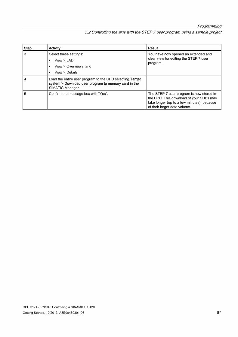
Step Activity Result 3 Select these settings:
• View > LAD, • View > Overviews, and • View > Details.
You have now opened an extended and clear view for editing the STEP 7 user program.
4 Load the entire user program to the CPU selecting Target system > Download user program to memory card in the SIMATIC Manager.
5 Confirm the message box with "Yes". The STEP 7 user program is now stored in the CPU. This download of your SDBs may take longer (up to a few minutes), because of their larger data volume.

Programming 5.2 Controlling the axis with the STEP 7 user program using a sample project
CPU 317T-3PN/DP: Controlling a SINAMICS S120 68 Getting Started, 10/2013, A5E00480391-06
CPU 317T-3PN/DP: Controlling a SINAMICS S120 Getting Started, 10/2013, A5E00480391-06 69
Trial run 6
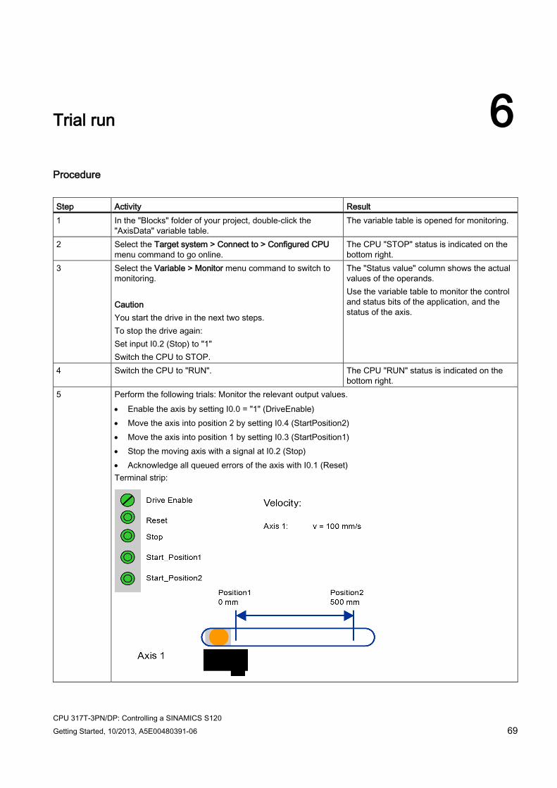
Procedure Step Activity Result 1 In the "Blocks" folder of your project, double-click the
"AxisData" variable table. The variable table is opened for monitoring.
2 Select the Target system > Connect to > Configured CPU menu command to go online.
The CPU "STOP" status is indicated on the bottom right.
3 Select the Variable > Monitor menu command to switch to monitoring. Caution You start the drive in the next two steps. To stop the drive again: Set input I0.2 (Stop) to "1" Switch the CPU to STOP.
The "Status value" column shows the actual values of the operands. Use the variable table to monitor the control and status bits of the application, and the status of the axis.
4 Switch the CPU to "RUN". The CPU "RUN" status is indicated on the bottom right.
5 Perform the following trials: Monitor the relevant output values. • Enable the axis by setting I0.0 = "1" (DriveEnable) • Move the axis into position 2 by setting I0.4 (StartPosition2) • Move the axis into position 1 by setting I0.3 (StartPosition1) • Stop the moving axis with a signal at I0.2 (Stop) • Acknowledge all queued errors of the axis with I0.1 (Reset) Terminal strip:

Trial run
CPU 317T-3PN/DP: Controlling a SINAMICS S120 70 Getting Started, 10/2013, A5E00480391-06
CPU 317T-3PN/DP: Controlling a SINAMICS S120 Getting Started, 10/2013, A5E00480391-06 71
Special case - controlling a virtual axis 7
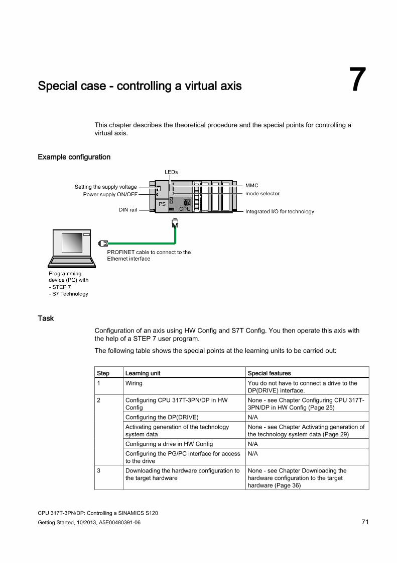
This chapter describes the theoretical procedure and the special points for controlling a virtual axis.
Example configuration
Task Configuration of an axis using HW Config and S7T Config. You then operate this axis with the help of a STEP 7 user program.
The following table shows the special points at the learning units to be carried out:
Step Learning unit Special features 1 Wiring You do not have to connect a drive to the
DP(DRIVE) interface. 2
Configuring CPU 317T-3PN/DP in HW Config
None - see Chapter Configuring CPU 317T-3PN/DP in HW Config (Page 25)
Configuring the DP(DRIVE) N/A Activating generation of the technology system data
None - see Chapter Activating generation of the technology system data (Page 29)
Configuring a drive in HW Config N/A Configuring the PG/PC interface for access to the drive
N/A
3 Downloading the hardware configuration to the target hardware
None - see Chapter Downloading the hardware configuration to the target hardware (Page 36)
Special case - controlling a virtual axis
CPU 317T-3PN/DP: Controlling a SINAMICS S120 72 Getting Started, 10/2013, A5E00480391-06
Step Learning unit Special features 4 Configuring a drive in S7T Config N/A 5 Configuring an axis / axes in S7T Config In the "Axis configuration... - Axis type":
"Linear" dialog box select "virtual" and then accept the default configuration data. See Chapter Configuring axes in S7T Config (Page 56).
6 Creating technology data blocks None - see Chapter Creating technology data blocks (Page 65)
7 Controlling the axis with the STEP 7 user program
None - see Chapter Controlling the axis with the STEP 7 user program using a sample project (Page 66)
8 Trial run Since no drive is connected, use the variable table in order to monitor the control and status bits of the application as well as the status of the axis. See Chapter Trial run (Page 69)
Diagnostics/troubleshooting Incorrect operator input, faulty wiring or inconsistent configuration data may lead to errors.
For information on how to analyze such errors and messages, refer to the S7-Technology manual.
Service and support on the Internet In addition to our documentation, we offer a comprehensive knowledge base on the Internet (http://www.siemens.com/automation/service&support). There you will find:
● The newsletter that provides you with latest information related to your products
● Your appropriate documentation, using our Service & Support search engine
● An international bulletin board where users and specialists can share their knowledge
● Your local Siemens partner for Automation & Drives in our Partner database
● Information about local service, repairs, and spare parts. Lots more is available under "Services".