Embed Size (px)
Citation preview


C =
C =
C =
C = COMPRESSOR CAPACITY IN CFM
V = RECEIVER & PIPING VOLUME IN CU. FT.
P2 = FINAL CUT OUT PRESSURE PSIA= 100 PSIG + 14.7 = 114.7 PSIA
P1 = INITIAL PRESSURE PSIA= 70 PSIG + 14.7 = 84.7 PSIA
V (P2 - P1) 60 SEC.(14.7) (TIME-SEC.)
* Assume the receiver and piping volume were 80 cu. ft.* Assume the pump-up time is 15 seconds.Then solve:
(80) (114.7 - 84.7) (60)(14.7) (15)
144,000220.5
C = 653 cubic ft./min. = actual capacity of existing air compressor
1
DETERMINING YOURAIR REQUIREMENTS
A relatively simple procedure to see if additional compressor capacity(CFM) is required can be performed in any plant or compressedair-using operation.Most general compressor air operations supply 100 PSIG at thecompressor and deliver a minimum of 90 PSIG to the using air tool. Forlowest possible power cost, this means compressor has a “cut outpressure” or unloads at 100 PSIG and “cut-in” or loads at 90 PSIGreceiver or system pressure. With these known figures (or whateverunload and load figures a particular system utilizes), we can determinethe following:If the receiver is below the normal cut-in point (90 PSIG) or does notgradually rise to the cut-out point (100 PSIG), more air is probablyneeded. Always check, of course, that there are no significant leaksand that the unloading and control system on the compressor arefunctioning correctly.NOTE: If the compressor must operate at more than 100 PSIG to get90 PSIG at the tools, check the distribution system for piping size orcheck points. The pipe may be too small or a single choke point toosmall for the system’s total demand (flow) or length.
CHECKING EXISTINGCOMPRESSOR CAPACITY
Running a timed pump-up test is a relatively accurate way to checkyour existing air compressor’s capacity or output. This will confirm thatyour shortage of compressed air is not due to a worn unit or amalfunction.Check the receiver volume in cubic feet. Check the pipe volumebetween the compressor and receiver in cubic feet. Operate thecompressor at load. Close the air valve between the receiver and plantair system. Drain the receiver down to 70 PSIG. Close the drain valvequickly. Record in seconds the required time to pump to 100 PSIG.Now work the following equation:If this is close to the rated capacity of your air compressor, then you canbe relatively sure the demand on your air system is too high and youneed additional air.
28
GENERAL TERMS CONTINUED
PISTON DISPLACEMENT:Is the volume swept by the piston, generally expressed in cubic feet perminute (CFM). For multi-stage compressors, the piston displacementof the first stage only is commonly stated as that of the entire machine.
ACTUAL CAPACITY:Is the quantity of gas actually compressed and delivered to thedischarge system by the compressor at rated speed and under ratedpressure conditions. Actual capacity is expressed in cubic feet perminute at the temperature and pressure conditions existing at the inletto the first stage.
VOLUMETRIC EFFICIENCY:Is the ratio of actual capacity to piston displacement, generally statedas percentage.
FREE AIR:Generally describes air at room or ambient temperatures and pressures,that is, normal atmospheric conditions. In other words, the term free airdescribes the air actually taken into the suction of a compressor whichtakes air from the surrounding atmosphere.
STANDARD CONDITIONS:Are not universally defined; therefore, since compressor capacities aresometimes expressed in standard cubic feet per minute (SCFM), it isnecessary to identify, before the compressor can be sized, (1) thestandard pressure condition; (2) the standard temperature condition;(3) the compressor suction pressure condition, and; (4) thecompressor suction temperature condition. The most popularidentification for standard pressure and temperature conditions is 14.5PSIA or 60❍F.
BRAKE HORSEPOWER (bhp):Is the measured horsepower input at the compressor shaft. Thehorsepower output of the driver must equal or exceed the compressorbhp plus any drive losses.
LOAD FACTOR:Is the ratio of the available demand for compressed air during a certainperiod of time to the maximum rated output capacity of the compressor.
NOTES:

326
TERMINOLOGY CONTINUED
UNLOAD (No Load):Air compressor continues to run (usually at FULL RPM), but NO air isdelivered because intake is either “closed off” or “modified”, NOT allow-ing inlet air to be trapped.
“MODULATING” UNLOAD:Air compressor continues to run and air supply is matched to demandby “partial unloading”. This is usually accomplished by a “regulatorcontrolled floating inlet”.
START-STOP CONTROL:Air supply is matched to demand by actual starting and stopping of theunit.
CUT-IN/CUT-OUT PRESSURE:The settings on a pressure switch used to either “load or unload” the aircompressor on “constant speed” application. The “cut-out” pressure isalso referred to as “maximum pressure”, the point at which there is NOAIR DELIVERED. The “cut-in” pressure is also referred as“minimum pressure” - the pressure that the system is allowed to fall tobefore additional air volume is called for. The compressor runs at fullload between cut-in and cut-out.
VARIABLE DISPLACEMENT CONTROLS:Also called “Rotor Length Adjustment” in oil cooled Rotary Screwcontrols. Particularly efficient in holding constant speed from 60% to100% capacity variable speed control. Below this usually goes to “blowdown” and idle.
VARIABLE SPEED CONTROL:Most commonly applied in oil cooled Rotary Screws. Very efficient fromabout 50% to 100% capacity. Below 50% usually defaults to modula-tion of Blow Down and idle.
RATED PRESSURE:The operating pressure at which the air compressor’s performance (CFMand BHP - Horsepower required) is measured.
SPECIFIC POWER:Used to compare air compressor efficiency unless otherwise stated.Usually in form of BHP/100 ACFM or CFM/HP.
GENERAL TERMS
COMPRESSORS:Are machines which compress air or gases from atmospheric pressureto a higher discharge pressure.
BOOSTER COMPRESSORS:Are machines which compress air or gases from a pressure higherthan atmospheric to a still higher discharge pressure.
VACUUM PUMPS:Are machines designed for compressing air or gases from an initialpressure which is below atmospheric to a pressure which is at or closeto atmospheric pressure.
RECIPROCATING COMPRESSORS:Are positive displacement machines used to increase the pressure of adefinite volume of gas by volume reduction. The compressing elementis a simple piston which reciprocates back and forth in a cylinder.
COMMON LEAK PROBLEM AREAS
COUPLINGS, HOSES, TUBES AND FITTINGS• Tubes and push-to-lock fittings are common problems.
DISCONNECTS• O-rings required to complete the seal may be missing.
FILTERS, REGULATORS AND LUBRICATORS (FRL’s)• Low first-cost improperly installed FRL’s often leak.
OPEN CONDENSATE TRAPS• Improperly operating solenoids and dirty seals are often problem
areas.
PIPE JOINTS• Missed welds are a common problem.
CONTROL AND SHUT-OFF VALVES• Worn packing through the stem can cause leaks.
POINT OF USE DEVICES• Old or poorly maintained tools can have internal leaks.
FLANGES• Missed welds are a common problem.
CYLINDER ROD PACKING• Worn packing materials can cause leaks.
THREAD SEALANTS• Incorrect and/or improperly applied thread sealants cause leaks.
HOW DO YOU FIND LEAKS?Since air leaks are almost impossible to see, other methods must beused to locate them. The best way to detect leaks is to use anultrasonic acoustic detector, which can recognize the high frequencyhissing sounds associated with air leaks. These portable units consistof directional microphones, amplifiers, and audio filters, and usuallyhave either visual indicators or earphones to detect leaks. A simplermethod is to apply soapy water with a paint brush to suspect areas.Although reliable, this method can be time consuming. Other methodsinclude: smoke sticks, candles, foam, manometers and stethoscopes.Ultrasonic detectors can find mid to large sized leaks. The advantagesof ultrasonic leak detection include: versatility, speed, ease of use, theability to perform tests while equipment is running and the ability to finda wide variety of leaks.
HOLE DIA. AIR LEAKAGE AT 100 PSI COST PER YEARIN. CFM $.06 KWH
1/32 1.62 $1581/16 6.5 $6331/8 26 $2,5321/4 104 $10,130
WHAT DO SYSTEM LEAKS COST?• Determine size of leak either through calculation or actual size of
orifice.
• 1/4 inch orifice can pass 104 CFM @ 100 PSIG.
• A typical 25 horsepower oil flooded Rotary Screw Air Compressor.
• At 6 cents a kW and 8,000 hours of operation, this can equal$9,946.00.
USEFUL FORMULAS
1. COMP. RPM =
2. MOTOR PULLEY p.d. =
3. COMP. PULLEY p.d. =
4. MOTOR RPM =
5. FREE AIR = piston displacement x volumetric eff. (%)
=
=
=
=
=
= x
=
motor pulley p.d. x motor RPMcomp. pulley p.d.
comp. pulley p.d. x comp. RPMmotor RPM
motor pulley p.d. x motor RPMcomp. RPM
comp. pulley p.d. x comp. RPMmotor pulley p.d.
6. REQUIRED PISTON free airDISPLACEMENT vol. eff.
7. PISTON DISPLACE- Cyl. bore x Cyl. bore x stroke in In. x RPMMENT IN CU.FT. MIN* 2200
8. CU. FT. COM- cu. ft. free air x atmospheric pressurePRESSED AIR (PSIG + 14.7)
9. CU. FT. cu. ft. compressed air x (PSIG + 14.7)FREE AIR atmospheric pressure
10. CU. FT. FREE AIRREQ’D TO RAISE vol. of rec. in cu. ft. x PSIGREC. FROM 0 GAUGE atmospheric pressureTO FINAL PRESSURE
11. CU. FT. FREE AIRREQ’D TO RAISE REC.FROM SOME PRESS. vol. of rec. (final PSIG – initial PSIG)GREATER THAN 0 in cu. ft. (atmospheric pressure)GAUGE TO A FINALHIGHER PRESSURE
12. PISTON SPEED IN 2 x stroke (in inches) x RPMFT. PER MIN. 12
13. GALLONS =
14. CU. FT. = gallons x .134
15. TOTAL FORCE INLBS. OF AIR = xCYLINDER
16. CFM OF FREEAIR REQUIREDTO OPERATE = x xAIR CYLINDER(SINGLE ACTING)
For Double Acting Cylinders Multiply by 2.
* Piston displacement for multi-stage compressors - only the lowpressure cylinder is considered.
cu. ft..134
Area of Cylinder PSIG of airDia. in sq. inches press. used
Vol. of Cyl. Cycles (Gauge Press. + 14.7)in cu. ft. per min. (14.7)
524
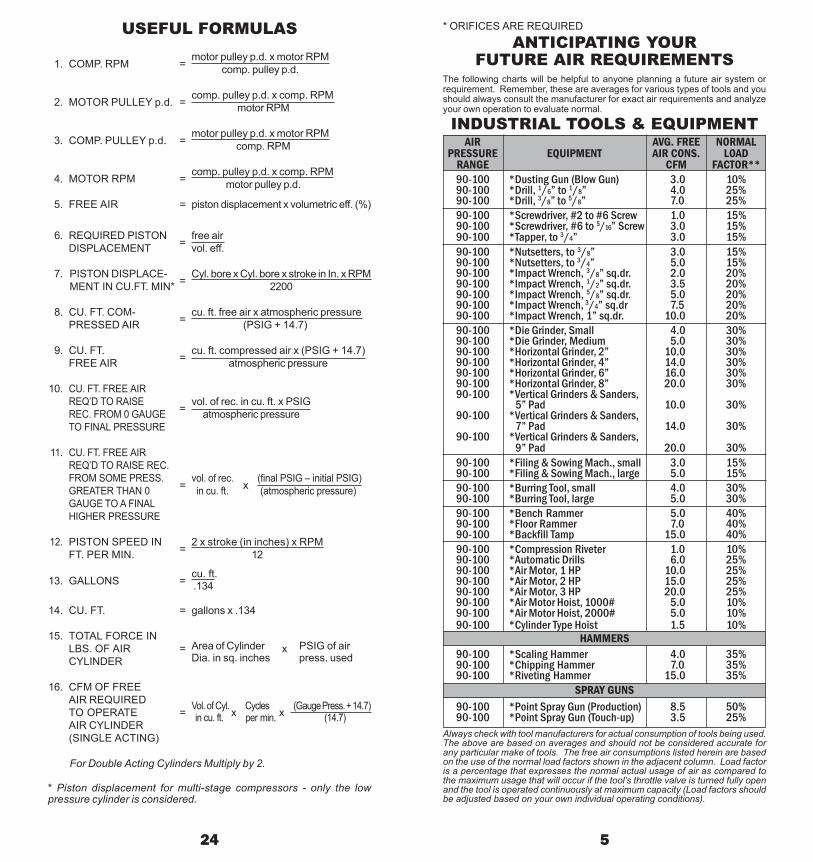
INDUSTRIAL TOOLS & EQUIPMENTAIR AVG. FREE NORMAL
PRESSURE EQUIPMENT AIR CONS. LOADRANGE CFM FACTOR**
Always check with tool manufacturers for actual consumption of tools being used.The above are based on averages and should not be considered accurate forany particular make of tools. The free air consumptions listed herein are basedon the use of the normal load factors shown in the adjacent column. Load factoris a percentage that expresses the normal actual usage of air as compared tothe maximum usage that will occur if the tool’s throttle valve is turned fully openand the tool is operated continuously at maximum capacity (Load factors shouldbe adjusted based on your own individual operating conditions).
ANTICIPATING YOURFUTURE AIR REQUIREMENTS
The following charts will be helpful to anyone planning a future air system orrequirement. Remember, these are averages for various types of tools and youshould always consult the manufacturer for exact air requirements and analyzeyour own operation to evaluate normal.
90-100 *Dusting Gun (Blow Gun) 3.0 10%90-100 *Drill, 1/6” to 1/8” 4.0 25%90-100 *Drill, 3/8” to 5/8” 7.0 25%90-100 *Screwdriver, #2 to #6 Screw 1.0 15%90-100 *Screwdriver, #6 to 5/16” Screw 3.0 15%90-100 *Tapper, to 3/4” 3.0 15%90-100 *Nutsetters, to 3/8” 3.0 15%90-100 *Nutsetters, to 3/4” 5.0 15%90-100 *Impact Wrench, 3/8” sq.dr. 2.0 20%90-100 *Impact Wrench, 1/2” sq.dr. 3.5 20%90-100 *Impact Wrench, 5/8” sq.dr. 5.0 20%90-100 *Impact Wrench, 3/4” sq.dr 7.5 20%90-100 *Impact Wrench, 1” sq.dr. 10.0 20%90-100 *Die Grinder, Small 4.0 30%90-100 *Die Grinder, Medium 5.0 30%90-100 *Horizontal Grinder, 2” 10.0 30%90-100 *Horizontal Grinder, 4” 14.0 30%90-100 *Horizontal Grinder, 6” 16.0 30%90-100 *Horizontal Grinder, 8” 20.0 30%90-100 *Vertical Grinders & Sanders,
5” Pad 10.0 30%90-100 *Vertical Grinders & Sanders,
7” Pad 14.0 30%90-100 *Vertical Grinders & Sanders,
9” Pad 20.0 30%90-100 *Filing & Sowing Mach., small 3.0 15%90-100 *Filing & Sowing Mach., large 5.0 15%90-100 *Burring Tool, small 4.0 30%90-100 *Burring Tool, large 5.0 30%90-100 *Bench Rammer 5.0 40%90-100 *Floor Rammer 7.0 40%90-100 *Backfill Tamp 15.0 40%90-100 *Compression Riveter 1.0 10%90-100 *Automatic Drills 6.0 25%90-100 *Air Motor, 1 HP 10.0 25%90-100 *Air Motor, 2 HP 15.0 25%90-100 *Air Motor, 3 HP 20.0 25%90-100 *Air Motor Hoist, 1000# 5.0 10%90-100 *Air Motor Hoist, 2000# 5.0 10%90-100 *Cylinder Type Hoist 1.5 10%
HAMMERS90-100 *Scaling Hammer 4.0 35%90-100 *Chipping Hammer 7.0 35%90-100 *Riveting Hammer 15.0 35%
SPRAY GUNS90-100 *Point Spray Gun (Production) 8.5 50%90-100 *Point Spray Gun (Touch-up) 3.5 25%
* ORIFICES ARE REQUIRED
1515
1515
1520
3045
6080
9010
011
015
020
022
525
035
045
060
080
0
45.
68
1010
1525
3040
6080
100
100
150
200
200
300
350
400
500
600
722
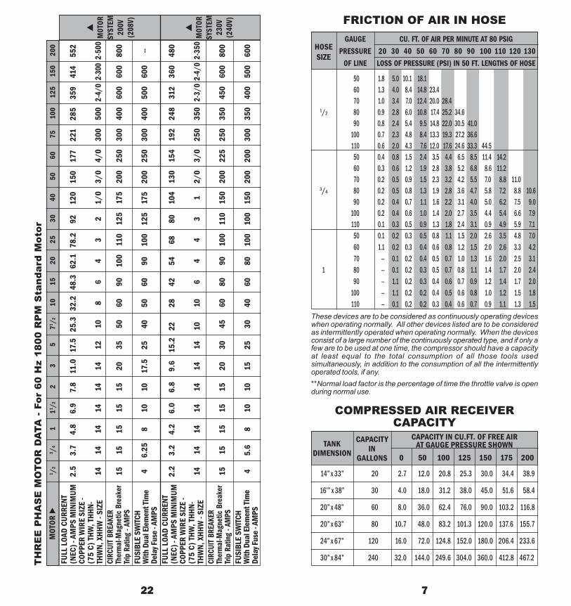
14” x 33” 20 2.7 12.0 20.8 25.3 30.0 34.4 38.9
16’” x 38” 30 4.0 18.0 31.2 38.0 45.0 51.6 58.4
20” x 48” 60 8.0 36.0 62.4 76.0 90.0 103.2 116.8
20” x 63” 80 10.7 48.0 83.2 101.3 120.0 137.6 155.7
24” x 67” 120 16.0 72.0 124.8 152.0 180.0 206.4 233.6
30” x 84” 240 32.0 144.0 249.6 304.0 360.0 412.8 467.2
50 1.8 5.0 10.1 18.160 1.3 4.0 8.4 14.8 23.470 1.0 3.4 7.0 12.4 20.0 28.4
1/2 80 0.9 2.8 6.0 10.8 17.4 25.2 34.690 0.8 2.4 5.4 9.5 14.8 22.0 30.5 41.0
100 0.7 2.3 4.8 8.4 13.3 19.3 27.2 36.6110 0.6 2.0 4.3 7.6 12.0 17.6 24.6 33.3 44.5
50 0.4 0.8 1.5 2.4 3.5 4.4 6.5 8.5 11.4 14.260 0.3 0.6 1.2 1.9 2.8 3.8 5.2 6.8 8.6 11.270 0.2 0.5 0.9 1.5 2.3 3.2 4.2 5.5 7.0 8.8 11.0
3/4 80 0.2 0.5 0.8 1.3 1.9 2.8 3.6 4.7 5.8 7.2 8.8 10.690 0.2 0.4 0.7 1.1 1.6 2.2 3.1 4.0 5.0 6.2 7.5 9.0
100 0.2 0.4 0.6 1.0 1.4 2.0 2.7 3.5 4.4 5.4 6.6 7.9110 0.1 0.3 0.5 0.9 1.3 1.8 2.4 3.1 0.9 4.9 5.9 7.1
50 0.1 0.2 0.3 0.5 0.8 1.1 1.5 2.0 2.6 3.5 4.8 7.060 1.1 0.2 0.3 0.4 0.6 0.8 1.2 1.5 2.0 2.6 3.3 4.270 -- 0.1 0.2 0.4 0.5 0.7 1.0 1.3 1.6 2.0 2.5 3.1
1 80 -- 0.1 0.2 0.3 0.5 0.7 0.8 1.1 1.4 1.7 2.0 2.490 -- 1.1 0.2 0.3 0.4 0.6 0.7 0.9 1.2 1.4 1.7 2.0
100 -- 1.1 0.2 0.2 0.4 0.5 0.6 0.8 1.0 1.2 1.5 1.8110 -- 0.1 0.2 0.2 0.3 0.4 0.6 0.7 0.9 1.1 1.3 1.5
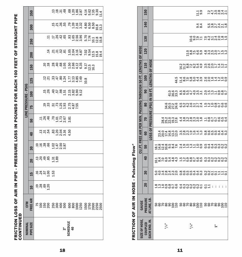
FRICTION OF AIR IN HOSE
HOSESIZE
GAUGE CU. FT. OF AIR PER MINUTE AT 80 PSIGPRESSURE 20 30 40 50 60 70 80 90 100 110 120 130
OF LINE LOSS OF PRESSURE (PSI) IN 50 FT. LENGTHS OF HOSE
These devices are to be considered as continuously operating deviceswhen operating normally. All other devices listed are to be consideredas intermittently operated when operating normally. When the devicesconsist of a large number of the continuously operated type, and if only afew are to be used at one time, the compressor should have a capacityat least equal to the total consumption of all those tools usedsimultaneously, in addition to the consumption of all the intermittentlyoperated tools, if any.**Normal load factor is the percentage of time the throttle valve is openduring normal use.
COMPRESSED AIR RECEIVERCAPACITY
CAPACITYIN
GALLONS
TANKDIMENSION
CAPACITY IN CU.FT. OF FREE AIRAT GAUGE PRESSURE SHOWN
0 50 100 125 150 175 200
TH
RE
E P
HA
SE
MO
TOR
DA
TA -
For
60
Hz
1800
RP
M S
tand
ard
Mot
orM
OTOR
1 /2
3 /41
11 /22
35
71 /210
1520
2530
4050
6075
100
125
150
200
1515
1515
1520
3550
6090
100
110
125
175
200
250
300
400
600
600
800
46.
258
1010
17.5
2540
5060
9010
012
517
520
025
030
040
050
060
0--
MOT
ORSY
STEM
200V
(208
V)
MOT
ORSY
STEM
230V
(240
V)
2.5
3.7
4.8
6.9
7.8
11.0
17.5
25.3
32.2
48.3
62.1
78.2
9212
015
017
722
128
535
941
455
2
1414
1414
1414
1210
86
43
21/
03/
04/
030
050
02-
4/0
2-30
02-
500
2.2
3.2
4.2
6.0
6.8
9.6
15.2
2228
4254
6880
104
130
154
192
248
312
360
480
1414
1414
1414
1410
106
44
31
2/0
3/0
250
350
2-3/
02-
4/0
2-35
0
FULL
LOA
D CU
RREN
T(N
EC) -
AM
PS M
INIM
UMCO
PPER
WIR
E SI
ZE -
(75❍
C) TH
W, T
HHN-
THW
N, X
HHW
- SI
ZECI
RCUI
T BRE
AKER
Ther
mal-M
agne
tic B
reak
erTri
p Ra
ting -
AM
PSFU
SIBL
E SW
ITCH
With
Dua
l Ele
men
t Tim
eDe
lay F
use -
AM
PSFU
LL L
OAD
CURR
ENT
(NEC
) - A
MPS
MIN
IMUM
COPP
ER W
IRE
SIZE
-(7
5❍
C) TH
W, T
HHN-
THW
N, X
HHW
- SI
ZECI
RCUI
T BRE
AKER
Ther
mal-M
agne
tic B
reak
erTri
p Ra
ting -
AM
PSFU
SIBL
E SW
ITCH
With
Dua
l Ele
men
t Tim
eDe
lay F
use -
AM
PS

W =
Table is based on 100% coefficient of flow. For well rounded entrance, multiply valuesby 0.97. For sharp edged orifices a multiplier of 0.61 may be used for approximateresults. Values for pressures from 1 to 15 lbs. gauge calculated by standard adiabaticformula. Values for pressures above 15 lbs. gauge calculated by approximate formulaproposed by S.A.
Moss. Where:0.5303 ACp1 W = discharge in lbs. per sec. T1 A = area of orifice in sq. in.
C = Coefficient of flowP1 = Upstream total pressure in lbs. per sq. in absoluteT1 = Upstream temperature in ❍F abs.Values used in calculating above table were:C = 1.0, p1 = gauge pressure + 14.7 lbs./sq. in.T1 = 530 ❍F abs.Weights (W) were converted to volumes using density factor of 0.07494 lbs./cu. ft. This iscorrect for dry air 14.7 lbs. per sq. in. absolute pressure and 70❍F. Formula cannot be usedwhere p1 is less than two times the downstream pressure.
20 9
DIAMETER OF ORIFICE1/64” 1/32” 1/16” 1/8” 1/4” 3/8” 1/2” 5/8” 3/4” 7/8” 1”
Discharge in cubic feet of free air per minute1 .028 .112 .450 1.80 7.18 16.2 28.7 45.0 64.7 88.1 1152 .040 .158 .633 2.53 10.1 22.8 40.5 63.3 91.2 124 1623 .048 .194 .775 3.10 12.4 27.8 49.5 77.5 111 152 1984 .056 .223 .892 3.56 14.3 32.1 57.0 89.2 128 175 2285 .062 .248 .993 3.97 15.9 35.7 63.5 99.3 143 195 2546 .068 .272 1.09 4.34 17.4 39.1 69.5 109 156 213 2787 .073 .293 1.17 4.68 18.7 42.2 75.0 117 168 230 3009 .083 .331 1.32 5.30 21.2 47.7 84.7 132 191 260 339
12 .095 .379 1.52 6.07 24.3 54.6 97.0 152 218 297 38815 .105 .420 1.68 6.72 26.9 60.5 108 168 242 329 43020 .123 .491 1.96 7.86 31.4 70.7 126 196 283 385 50325 .140 .562 2.25 8.98 35.9 80.9 144 225 323 440 57530 .158 .633 2.53 10.1 40.5 91.1 162 253 365 496 64835 .176 .703 2.81 11.3 45.0 101 180 281 405 551 72040 .194 .774 3.10 12.4 49.6 112 198 310 446 607 79345 .211 .845 3.38 13.5 54.1 122 216 338 487 662 86550 .229 .916 3.66 14.7 58.6 132 235 366 528 718 93860 .264 1.06 4.23 16.9 67.6 152 271 423 609 828 108270 .300 1.20 4.79 19.2 76.7 173 307 479 690 939 122780 .335 1.34 5.36 21.4 85.7 193 343 536 771 1050 137190 .370 1.48 5.92 23.7 94.8 213 379 592 853 1161 1516
100 .406 1.62 6.49 26.0 104 234 415 649 934 1272 1661110 .441 1.76 7.05 28.2 113 254 452 705 1016 1383 1806120 .476 1.91 7.62 30.5 122 274 488 762 1097 1494 1951125 .494 1.98 7.90 31.6 126 284 506 790 1138 1549 2023150 .582 2.37 9.45 37.5 150 338 600 910 1315 1789 2338200 .761 3.10 12.35 49.0 196 441 784 1225 1764 2401 3136250 .935 3.80 15.18 60.3 241 542 964 1508 2169 2952 3856300 .995 4.88 18.08 71.8 287 646 1148 1795 2583 3515 4592400 1.220 5.98 23.81 94.5 378 851 1512 2360 3402 4630 6048500 1.519 7.41 29.55 117.3 469 1055 1876 2930 4221 5745 7504750 2.240 10.98 43.85 174.0 696 1566 2784 4350 6264 8525 11136
1000 2.985 14.60 58.21 231.0 924 2079 3696 5790 8316 11318 14784
DISCHARGE OF AIRTHROUGH AN ORIFICE
In cubic feet of free air per minute at standard atmospheric pressure of14.7 lb. per sq. in. absolute and 70❍F
GAUGEPRESSURE
BEFOREORIFICEIN LBS.
PERSQ.IN.
FRIC
TIO
N L
OS
S O
F A
IR I
N P
IPE
- P
RE
SS
UR
E L
OS
S I
N P
OU
ND
S F
OR
EA
CH
100
FE
ET
OF
ST
RA
IGH
T P
IPE
CO
NT
INU
ED
300
.36
.30
.26
.20
.16
.13
.10
500
.94
.78
.67
.52
.43
.36
.26
.20
.17.1
4.1
175
01.
691.
441.
12.9
2.7
8.5
6.4
4.3
6.3
0.2
3.1
9.1
6.1
410
002.
501.
941.
591.
34.9
7.7
6.6
2.5
3.4
1.3
3.2
8.2
415
004.
303.
522.
982.
151.
681.
381.
17.9
0.7
3.6
1.5
320
005.
293.
812.
992.
472.
081.
601.
301.
09.9
425
005.
964.
673.
833.
262.
502.
021.
701.
4730
008.
586.
715.
514.
683.
582.
912.
452.
1135
009.
157.
506.
374.
893.
963.
342.
8840
0011
.99.
808.
316.
365.
164.
353.
7645
0012
.410
.58.
066.
555.
504.
7550
0015
.313
.09.
958.
076.
805.
8660
0014
.311
.69.
788.
4570
0019
.515
.913
.411
.5
3”SC
HEDU
LE40
NOM
INAL
CFM
PIPE
SIZ
EFR
EE A
IRLI
NE P
RESS
URE
- PSI
G10
1520
3040
5075
100
125
150
200
250
300
350
501.
85.
010
.118
.160
1.3
4.0
8.4
14.8
23.4
701.
03.
47.
012
.420
.028
.480
0.9
2.8
6.0
10.8
17.4
25.2
34.6
900.
82.
45.
49.
514
.822
.030
.541
.010
00.
72.
34.
88.
413
.319
.327
.236
.611
00.
62.
04.
37.
612
.017
.624
.633
.344
.550
0.4
0.8
1.5
2.4
3.5
4.4
6.5
8.5
11.4
14.2
600.
30.
61.
21.
92.
83.
85.
26.
88.
611
.270
0.2
0.5
0.9
1.5
2.3
3.2
4.2
5.5
7.0
8.8
11.0
800.
20.
50.
81.
31.
92.
83.
64.
75.
87.
28.
810
.690
0.2
0.4
0.7
1.1
1.6
2.3
3.1
4.0
5.0
6.2
7.5
9.0
100
0.2
0.4
0.6
1.0
1.4
2.0
2.7
3.5
4.4
5.4
6.6
7.9
9.4
11.1
110
0.1
0.3
0.5
0.9
1.3
1.8
2.4
3.1
3.9
4.9
5.9
7.18.
49.
950
0.1
0.2
0.3
0.5
0.8
1.1
1.5
2.0
2.6
3.5
4.8
7.0
601.
10.
20.
30.
40.
60.
81.
21.
52.
02.
63.
34.
25.
57.
270
--0.
10.
20.
40.
50.
71.
01.
31.
62.
02.
53.
13.
84.
780
--0.
10.
20.
30.
50.
70.
81.
11.
41.
72.
02.
42.
73.
590
--1.
10.
20.
30.
40.
60.
70.
91.
21.
41.
72.
02.
42.
810
0--
1.1
0.2
0.2
0.4
0.5
0.6
0.8
1.0
1.2
1.5
1.8
2.1
2.4
110
--0.
10.
20.
20.
30.
40.
60.
70.
91.
11.
31.
51.
82.
1
11
FRIC
TIO
N O
F A
IR I
N H
OS
E -
Pul
sati
ng F
low
*
18
1 /2”
3 /4”
1”
CU.F
T. FR
EE A
IR P
ER M
IN. P
ASSI
NG TH
ROUG
H 50
FT. L
ENGT
HS O
F HOS
E20
3040
5060
7080
9010
011
012
013
014
015
0LO
SS O
F PRE
SSUR
E (P
SI) I
N 50
FT. L
ENGT
HS O
F HOS
E
SIZE
OF H
OSE,
GAUG
ECO
UPLE
DPR
ESSU
REEA
CH E
ND, I
N.AT
LINE
, LB.
FRIC
TIO
N L
OS
S O
F A
IR I
N P
IPE
- P
RE
SS
UR
E L
OS
S I
N P
OU
ND
S F
OR
EA
CH
100
FE
ET
OF
ST
RA
IGH
T P
IPE
CO
NT
INU
ED
75.1
9.1
6.1
3.1
010
0.2
8.2
4.2
0.1
6.1
3.1
115
0.6
9.5
7.4
9.3
8.3
1.2
6.1
9.1
5.1
2.1
020
01.
201.
00.8
5.6
6.5
4.4
6.3
3.2
6.2
1.1
8.1
4.1
125
01.
531.
311.
02.8
3.7
0.5
1.4
0.3
3.2
8.2
1.17
.15
.13
300
1.89
1.47
1.20
1.01
.73
.57
.47
.40
.31
.26
.21
.18
400
2.50
2.04
1.73
1.25
.98
.80
.68
.52
.42
.36
.31
500
3.87
3.16
2.67
1.93
1.51
1.24
1.05
.81
.65
.55
.48
600
4.50
3.81
2.75
2.15
1.77
1.50
1.05
.93
.79
.68
800
4.87
3.82
3.13
2.66
2.04
1.65
1.39
1.20
1000
7.55
5.90
4.85
4.12
3.16
2.56
2.16
1.86
1250
9.12
7.49
6.35
4.87
3.96
3.32
2.87
1500
10.8
9.17
7.02
5.70
4.80
4.14
1750
12.5
9.54
7.74
6.50
5.62
2000
16.3
12.5
10.1
8.50
7.35
2250
15.8
12.8
10.8
9.30
2500
19.4
15.8
13.3
11.4
2”SC
HEDU
LE40
NOM
INAL
CFM
PIPE
SIZ
EFR
EE A
IRLI
NE P
RESS
URE
- PSI
G10
1520
3040
5075
100
125
150
200
250
300
350
1316
Inle
t tem
pera
ture
125
120
115
110
105
100
9590
Inle
t wat
er va
por -
lbs./
hr.
4.71
684.
1008
3.55
523.
0756
2.65
322.
2836
1.95
801.
6764
Lbs.
wate
r rem
oved
/hr.
4.29
003.
6740
3.12
842.
6588
2.22
641.
8565
1.53
121.
2496
Wat
er re
mov
ed, p
erce
nt90
.95
89.5
987
.99
86.1
283
.91
81.3
178
.20
74.5
4Pe
rcen
t of d
esig
n po
int
280.
223
9.9
204.
317
2.9
145.
412
1.1
100.
081
.6Se
nsib
le lo
ad -
btu.
/hr.
3181
2969
2757
2545
2333
2121
1908
1697
Late
nt lo
ad -
btu.
/hr.
4595
3935
3351
2837
2425
1989
1640
1338
Tota
l load
- btu
./hr
.76
7668
9461
0853
8247
5841
1035
4830
35Pe
rcen
t of d
esig
n21
6.3
194.
317
2.2
181.
713
4.1
115.
810
085
.5Op
erat
ion k
w./h
r..6
7.6
0.5
3.4
7.4
1.3
6.3
1.2
7
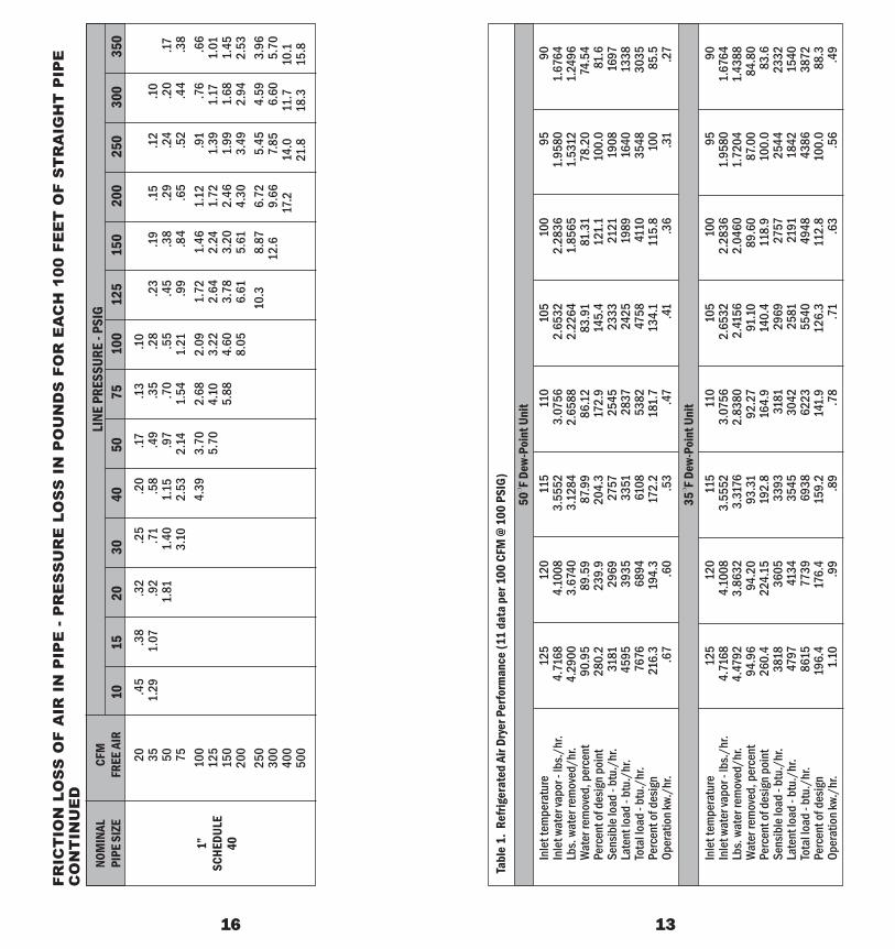
Tabl
e 1.
Ref
riger
ated
Air
Drye
r Per
form
ance
(11
data
per
100
CFM
@ 1
00 P
SIG)
50❍
F Dew
-Poi
nt U
nit
35❍
F Dew
-Poi
nt U
nit
Inle
t tem
pera
ture
125
120
115
110
105
100
9590
Inle
t wat
er va
por -
lbs./
hr.
4.71
684.
1008
3.55
523.
0756
2.65
322.
2836
1.95
801.
6764
Lbs.
wate
r rem
oved
/hr.
4.47
923.
8632
3.31
762.
8380
2.41
562.
0460
1.72
041.
4388
Wat
er re
mov
ed, p
erce
nt94
.96
94.2
093
.31
92.2
791
.10
89.6
087
.00
84.8
0Pe
rcen
t of d
esig
n po
int
260.
422
4.15
192.
816
4.9
140.
411
8.9
100.
083
.6Se
nsib
le lo
ad -
btu.
/hr.
3818
3605
3393
3181
2969
2757
2544
2332
Late
nt lo
ad -
btu.
/hr.
4797
4134
3545
3042
2581
2191
1842
1540
Tota
l load
- btu
./hr
.86
1577
3969
3862
2355
4049
4843
8638
72Pe
rcen
t of d
esig
n19
6.4
176.
415
9.2
141.
912
6.3
112.
810
0.0
88.3
Oper
atio
n kw.
/hr.
1.10
.99
.89
.78
.71
.63
.56
.49
20.4
5.3
8.3
2.2
5.2
0.17
.13
.10
351.
291.
07.9
2.7
1.5
8.4
9.3
5.2
8.2
3.1
9.1
5.1
2.1
050
1.81
1.40
1.15
.97
.70
.55
.45
.38
.29
.24
.20
.1775
3.10
2.53
2.14
1.54
1.21
.99
.84
.65
.52
.44
.38
100
4.39
3.70
2.68
2.09
1.72
1.46
1.12
.91
.76
.66
125
5.70
4.10
3.22
2.64
2.24
1.72
1.39
1.17
1.01
150
5.88
4.60
3.78
3.20
2.46
1.99
1.68
1.45
200
8.05
6.61
5.61
4.30
3.49
2.94
2.53
250
10.3
8.87
6.72
5.45
4.59
3.96
300
12.6
9.66
7.85
6.60
5.70
400
17.2
14.0
11.7
10.1
500
21.8
18.3
15.8
LINE
PRE
SSUR
E - P
SIG
1015
2030
4050
7510
012
515
020
025
030
035
0
1”SC
HEDU
LE40
FRIC
TIO
N L
OS
S O
F A
IR I
N P
IPE
- P
RE
SS
UR
E L
OS
S I
N P
OU
ND
S F
OR
EA
CH
100
FE
ET
OF
ST
RA
IGH
T P
IPE
CO
NT
INU
ED
NOM
INAL
CFM
PIPE
SIZ
EFR
EE A
IR

DETERMINING ADDITIONALCOMPRESSED AIR REQUIRED TO
BRING YOUR AIR SYSTEMBACK TO 100 PSIG
Once the actual existing compressed air capacity is known, it isrelatively easy to mathematically determine the air required to bring theair system up to 100 PSIG:
CFM P2
P1
653 (114.7) = 884 CFM84.7
Therefore, the total air capacity required to hold 100 PSIG is 884 CFMand the additional then is 884 - 653 or 231 cubic feet per minute.Additional compressed air is required to meet the current demand.
Depending on the type of system and type of air supply, a “leakage” or“unload factor” should be added to any requirement. This is generallyfrom 20% to 30% depending on the condition.
Using a 20% extra capacity factor, the total air requirement would thenbe 884 x 1.20 = 1060 CFM and an additional (1060 - 653) 408 CFMwould be recommended.
ANALYZING THE COST OFSYSTEM LEAKS
A shortage in capacity is often due to or certainly partially due to systemleakage. Air system leaks are a continuing source of lost power andshould always be minimized. A number of small leaks to that of a 1/4”orifice would at 100 PSIG pass CFM of compressed air. This is a25HP air compressor to you. A .04 per KWH operating 8,000 hoursper year, (3 shifts) this would cost you $6,600 in power cost to do nowork.
Defective tools, shut-off valves, packings, fit-ups, drain cocks, etc.,should be continually checked. Most plants can always afford themaintenance labor and parts to correct leaks. Total system leakagecan be identified by measuring time in seconds for the system (receiver)pressure to drop from 100 to 90 PSIG with no air supply or usage:
For example, assume the total receiver and piping of the system is 120cubic feet. If the plant has a 90 second bleed down rate is 90 PSIGwhen no production air is being used, this is leakage.
The calculated leakage capacity is:
(120) (114.7 - 104.7) (60) = 54 CFM(90) 14.7
TOTAL COMPRESSED AIR LEAKAGE = 54 CFM X 1.15 = 62 CFM
* Add 15% to adjust for the higher leakage rate at the 120 PSIG to 90PSIG (30 PSIG x .5)
* Any leakage rate beyond 5% of the total system should be corrected.
CFM (REQUIRED) =
CFM (REQUIRED) =
CFM (LEAKAGE) =
2 27
GENERAL TERMS CONTINUED
SINGLE-ACTING COMPRESSORS:Are machines which compress on only one side of the piston.Compression takes place on only one stroke per revolution of thecompressing element.
DOUBLE-ACTING COMPRESSORS:Are machines which compress on both sides of the piston. Therunning gear consists of a crank and crosshead mechanism with thepiston rod attached to the crosshead, and extending into thecompressor cylinder through a packing box. Compression takes placeon both strokes in each revolution.
AIR RECEIVERS:Are large tanks placed in compressed air systems. A receiver actsprimarily as a pulsation damper and warehouse for air. It also serves tocollect condensate. Consequently, it is advisable to equip receiverswith automatic moisture traps.
SINGLE STAGE COMPRESSORS:Are machines which use only one step or stage to compress from theinitial pressure to the final discharge pressure.
MULTI-STAGE COMPRESSORS:Are machines which use more than one step or stage to compress fromthe initial pressure to the final discharge pressure. For example, a twostage compressor compresses in two steps; a three stage compressorcompresses in three steps, etc.
INTERCOOLERS:Are heat exchangers used to remove the heat of compression betweenstages of compression on multi-stage compressors.
AFTERCOOLERS:Are heat exchangers designed to remove the heat of compression afterthe final stage of compression in addition to removing moisture fromthe compressed air.
MOISTURE SEPARATORS:Are used generally in conjunction with aftercoolers and intercoolers tocollect and remove the moisture which has condensed in compressedair lines.
AUTOMATIC MOISTURE TRAPS:Are devices designed to automatically eject from the system themoisture collected in the separator.
ABSOLUTE PRESSURE:Is the existing gauge pressure (as read on a gauge) plus atmosphericpressure. Atmospheric pressure at sea level is 14.7 PSIA; therefore,for 100 pounds gauge, the absolute pressure (PSIA) is 100 plus 14.7,or 114.7 PSIA.
RATIO OF COMPRESSION:Is the absolute discharge pressure divided by the absolute suctionpressure. For a compressor taking in atmospheric air at sea level andcompressing it to 100 pounds gauge, the ratio of compression is114.7/114.7 = 7.8.
(Note that in compressors, ratio of compression is a ratio of pressures.It should not be confused with the similar term used by internalcombustion engine manufacturers. In engines, ratio of compression isa ratio of volumes)
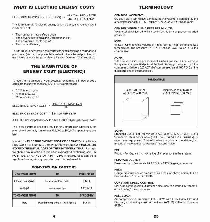
HP x .746 x HRS. x RATEMOTOR EFFICIENCY
WHAT IS ELECTRIC ENERGY COST?
ELECTRIC ENERGY COST (DOLLARS) =
This is the formula for electric energy cost in dollars, and you can see itis a function of:
• The number of hours of operation• The power used to drive the Compressor (HP)• The power rate (cents per kW)• The motor efficiency
This formula is acceptable as accurate for estimating and comparisonpurposes. (Your actual power bill can be further affected positively ornegatively by such things as Power Factor - Demand Charges, etc.).
THE MAGNITUDE OFENERGY COST (ELECTRIC)!
To see the magnitude of your potential expenditure in power cost,calculate the power cost of a 100 HP Air Compressor:
• 6,000 hours a year• Rate of $.07/kW• Motor efficiency .90
(100) (.746) (6,000) (.07).90
ELECTRIC ENERGY COST = $34,800 PER YEAR
A 100 HP Air Compressor would have a $34,800 per year power cost.
The initial purchase price of a 100 HP Air Compressor, lubricated, forplant air will probably range from $35,000 to $50,000 depending on thetype.
In short, the ELECTRIC ENERGY COST OF OPERATION in a HeavyDuty Cycle-Full Load 6,000 Hours (2 Shifts Plus)) CAN EQUAL OREXCEED THE INITIAL COST OF THE UNIT EVERY YEAR. Perhapswe should pay attention to this often overlooked continuing cost. APOSITIVE VARIANCE OF 15% - 25% in energy cost can be asignificant savings in any operation, and this is obtainable.
CONVERSION FACTORS
4 25
TERMINOLOGY
CFM DISPLACEMENT:CUBIC FEET PER MINUTE measures the volume “displaced” by theair compressor at full RPM - but not “Delivered Air” or “Usable Air”.
CFM DELIVERED CUBIC FEET PER MINUTE:Volume of air delivered to the system by the air compressor at ratedpressure.
ICFM:“INLET” CFM is rated volume of “Inlet” air (at “Inlet” conditions i.e.:temperature and pressure 14.7 PSIG at sea level) taken in to thecompressor.
ACFM:Is the actual cubic feet per minute of inlet compressed air delivered tothe system at a specified point at the final discharge pressure. i.e.: thecompressor delivers 625 ACFM of compressed air at 100 PSIG at thedischarge end of the aftercooler.
SCFM:Standard Cubic Feet Per Minute is ACFM or ICFM CONVERTED to“standard” intake conditions - (60❍F, 0% RH & 14.7 PSIG usually) forrating using equipment. To size for other than standard conditions, i.e.:altitude or hot weather “corrections” must be made.
PSI:Pounds Per Square Inch - A rating of air pressure in the system.
PSIA “ABSOLUTE”:Pressure. i.e.: Sea level - 14.7 PSIA or 0 PSIG (gauge pressure).
PSIG:Gauge pressure shows amount of air pressure above ambient; i.e.:Sea level = 0 PSIG = 14.7 PSIA.
CONSTANT SPEED CONTROL:Unit runs continuously but matches air supply to demand by “loading”or “unloading” the compressor.
FULL LOAD:Air compressor is running at FULL RPM with Fully Open Inlet andDischarge delivering maximum volume (ACFM) at Rated Pressure(PSM).
FOR EXAMPLE
Inlet = 700 ICFM Compressed to 625 ACFMat 14.7 PSIA, 0 PSIG at 114.7 PSIA, 100 PSIG
Kilowatt Hours (kW h) Horsepower Hours (hp h) 1.341 0
Watts (W) Horsepower (hp) 0.001341 0
TO CONVERT FROM TO DIVIDED BY
Bars Pounds Force per Sq. In. (lbf/in2) (PSI) 14.504
ELECTRIC ENERGY COST =
TO CONVERT FROM TO MULTIPLY BY

1515
1515
1515
1515
2035
4560
6080
9010
011
015
020
020
025
0
1.8
2.5
3.2
45
6.25
1015
2025
3040
5060
8090
100
150
175
200
300
6 23
AUTOMOTIVE SERVICEEQUIPMENT
AIR AVG. FREEPRESSURE EQUIPMENT AIR CONS.
RANGE CFM
70- 100 *Air Filter Cleaner 3.070- 100 *Body Polisher 2.070- 100 *Body Sander (Orbital) 5.070- 100 *Brake Tester 3.570- 100 *Carbon Remover 3.070- 100 *Carwasher 8.590- 100 Dusting Gun (Blow Gun) 2.5
120- 150 *Grease Gun 3.070- 100 *Panel Cutter 4.070- 90 Drill, 1/16” to 3/8” 4.0
125- 150 *Impact Wrench, 3/8” sq.dr. 2.0125- 150 *Impact Wrench, 1/2” sq.dr. 3.5125- 150 *Impact Wrench, 5/8” sq.dr. 5.0125- 150 *Impact Wrench, 3/4” sq.dr. 7.5125- 150 *Impact Wrench, 1” sq.dr. 10.0
70- 90 *Die Grinder 5.090- 100 *Vertical Disc Sanders 10.090- 100 *Filing & Sawing Machine, small 3.090- 100 *Filing & Sawing Machine, large 5.0
90- 100 *Burring Tool 5.0145- 175 Hydraulic Lift 6.0125- 150 Hydraulic Floor Jack 6.0120- 150 Pneumatic Garage Door 3.0
90- 100 Radiator Tester 1.090- 100 Spark Plug Cleaner 5.090- 100 Spark Plug Tester 0.5
HAMMERS
90- 100 *Air Hammer 4.090- 100 *Tire Hammer 12.0
125- 150 *Bead Breaker 12.0
SPRAY GUNS
90- 100 *Engine Cleaner 5.090- 100 *Paint Spray Gun (Production) 8.590- 100 *Paint Spray Gun (Touch-up) 3.590- 100 *Paint Spray Gun (Undercoating) 19.090- 100 Spring Oiler 4.0
TIRE TOOLS
125- 150 Rim Stripper 6.0125- 150 Tire Changer 1.0125- 150 Tire Inflation Line 1.5125- 150 Tire Spreader 1.0125- 150 *Vacuum Cleaner 6.5 TH
RE
E P
HA
SE
MO
TO
R D
ATA
- F
or 6
0 H
z 18
00 R
PM
Sta
ndar
d M
otor
CO
NT
INU
ED
MOT
OR
1 /23 /4
111 /2
23
571 /2
1015
2025
3040
5060
7510
012
515
020
0
1515
1515
1515
1520
2540
6070
8090
100
110
125
200
225
250
350
23.
24
5.6
6.25
815
2020
3040
5060
8010
010
015
017
520
025
035
0
MOT
ORSY
STEM
460V
(480
V)
MOT
ORSY
STEM
575V
(600
V)
1.1
1.6
2.1
3.0
3.4
4.8
7.6
1114
2127
3440
5265
7796
124
156
180
240
1414
1414
1414
1414
1410
108
86
43
12/
03/
04/
035
0
0.9
1.3
1.7
2.4
2.7
3.9
6.1
9.0
1117
2227
3241
5262
7799
125
144
192
1414
1414
1414
1414
1412
1010
86
64
31
2/0
3/0
250
FULL
LOA
D CU
RREN
T(N
EC) -
AM
PS M
INIM
UMCO
PPER
WIR
E SI
ZE -
(75❍
C) TH
W, T
HHN-
THW
N, X
HHW
- SI
ZECI
RCUI
T BRE
AKER
Ther
mal-M
agne
tic B
reak
erTri
p Ra
ting -
AM
PSFU
SIBL
E SW
ITCH
With
Dua
l Ele
men
t Tim
eDe
lay F
use -
AM
PSFU
LL L
OAD
CURR
ENT
(NEC
) - A
MPS
MIN
IMUM
COPP
ER W
IRE
SIZE
-(7
5❍
C) TH
W, T
HHN-
THW
N, X
HHW
- SI
ZECI
RCUI
T BRE
AKER
Ther
mal-M
agne
tic B
reak
erTri
p Ra
ting -
AM
PSFU
SIBL
E SW
ITCH
With
Dua
l Ele
men
t Tim
eDe
lay F
use -
AM
PS

8 21
1/8” 115 130 140 165
3/16” (*3) 260 290 320 375
1/4” (*4) 460 500 560 660
5/16” (*5) 725 825 900 1050
3/8” (*6) 1050 1155 1260 1475
7/16” (*7) 1450 1600 1750 2050
1/2” (*8) 1850 2000 2250 2650
5/8” (*10) 2900 3125 3520 4100
3/4” (*12) 4180 4500 5060 5950
1/8” 18 20 22 26
3/16” (*3) 41 45 49 58
1/4” (*4) 72 80 90 105
5/16” (*5) 113 125 140 160
3/8” (*6) 163 182 200 235
7/16” (*7) 215 240 270 315
1/2” (*8) 290 320 350 410
5/8” (*10) 454 500 550 640
3/4” (*12) 652 720 790 925
BLASTING DATA
APPROXIMATE AIR CONSUMPTION(CFM) PER BLAST NOZZLE
NOZZLESIZE
NOZZLE PRESSURE
80 PSI 90 PSI 100 PSI 120 PSI
NOZZLESIZE
NOZZLE PRESSURE
80 PSI 90 PSI 100 PSI 120 PSI
APPROXIMATE ABRASIVECONSUMPTION (LBS./HR.)
PER BLAST NOZZLE
Air volume and pressure are very important. The blasting productionrate will increase with higher blasting pressures and decrease with lowerblasting pressures. The National Association of Corrosion Engineersdata suggests that 1.5% of production is lost for each 1 PSI reduction inblast nozzle pressure. Pressure drop through the blast unit itself isnormally less than 1 PSI. Air pressure loss can be avoided by using theshortest possible hose of adequate size. S
ING
LE P
HA
SE
MO
TOR
DA
TA (
60 H
z)
MOT
ORSY
STEM
115V
(120
V)
MOT
OR
1 /61 /4
1 /31 /2
3 /41
11 /22
35
71 /210
MOT
ORSY
STEM
230V
(240
V)
1515
1520
2530
4050
7090
110
--
6.25
910
1520
2530
3050
8010
0--
FULL
LOA
D CU
RREN
T (NE
C) -
AMPS
MIN
IMUM
COP
PER
WIR
ESI
ZE -
(75❍
C) TH
W, T
HHN-
THW
N,XH
HW -
SIZE
CIRC
UIT B
REAK
ERTh
erm
al-M
agne
tic B
reak
er Tr
ipRa
ting -
AM
PSFU
SIBL
E SW
ITCH
With
Dua
l Ele
men
t Tim
e Del
ayFu
se - A
MPS
FULL
LOA
D CU
RREN
T (NE
C) -
AMPS
MIN
IMUM
COP
PER
WIR
ESI
ZE -
(75❍
C) TH
W, T
HHN-
THW
N,XH
HW -
SIZE
CIRC
UIT B
REAK
ERTh
erm
al-M
agne
tic B
reak
er Tr
ipRa
ting -
AM
PSFU
SIBL
E SW
ITCH
With
Dua
l Ele
men
t Tim
e Del
ayFu
se - A
MPS
2.2
2.9
3.6
4.9
6.9
810
1217
2840
50
1414
1414
1414
1414
1210
86
1515
1515
1515
2025
3560
8090
3.2
4.5
5.6
710
1215
2025
4060
60
4.4
5.8
7.2
9.8
13.8
1620
2434
5680
--
1414
1414
1414
1210
84
3--

10 19
LOSS OF AIR PRESSUREDUE TO FRICTION - IN PSI 100 FT.OF PIPE OR HOSE 100 PSI GAUGE
INITIAL PRESSURE
For longer or shorter lengths of pipe or hose, the friction loss isproportional to the length; i.e.: for 50 ft., one-half of the above; for 400 ft.,four times the above, etc.NOTES:1. These figures are for estimating - different types of pipe and hose
may have rougher linings and cause higher pressure drops.
2. Couplings and fittings increase the pressure drop some.
3. Lower initial pressures cause increased pressure drop.
4. Higher initial pressure causes lower pressure drop.Piping for a sample system of 3,000 CFM at 100 PSIG of central air, withfive 600 CFM uses figured according to the chart for loss of air pressuredue to friction.
CU. FT. EQUIVALENTFREE CU. FT.AIR COMPRESSED
PER MIN. AIR/MIN.
TYPICALNominal Diameter, In. (I.D.)
1/2 3/4 1 11/4 11/2 2 21/2 3 31/2 4
10 1.28 2.6 .1 .0320 2.56 6.9 .4 .11 .03 .0130 3.84 .59 .9 .25 .06 .0740 5.12 1.6 .45 .10 .0550 6.41 2.5 .69 .16 .07 .0260 7.68 3.6 1.00 .23 .10 .0370 8.96 4.9 1.40 .32 .14 .0480 10.24 6.5 1.80 .41 .18 .05 .0290 11.52 8.3 2.30 .52 .23 .06 .02
100 12.81 2.80 .65 .29 .08 .03125 15.82 4.90 1.0 .45 .12 .05150 19.23 6.30 1.5 .64 .17 .07 .02175 22.40 1.9 .87 .24 .09 .03200 25.62 2.6 1.14 .31 .12 .04 .02250 31.64 4.0 1.79 .49 .19 .06 .03300 38.44 5.8 2.58 .69 .27 .08 .04 .02350 44.80 3.51 .94 .36 .11 .05 .03400 51.24 4.58 1.21 .48 .15 .07 .04450 57.65 5.80 1.54 .59 .19 .09 .05500 63.28 7.16 1.92 .74 .23 .11 .06600 76.88 2.76 1.07 .34 .16 .08700 89.60 3.77 1.45 .46 .21 .11800 102.50 4.90 1.90 .59 .28 .14900 115.30 6.23 2.41 .76 .35 .18
1000 128.10 7.69 2.98 .93 .44 .221500 192.30 6.70 2.10 .98 .492000 256.20 3.74 1.73 .882500 316.40 5.84 2.72 1.383000 384.60 8.41 3.91 2.003500 447.80 5.82 2.724000 512.40 6.94 3.55
FRIC
TIO
N L
OS
S O
F A
IR I
N P
IPE
- P
RE
SS
UR
E L
OS
S I
N P
OU
ND
S F
OR
EA
CH
100
FE
ET
OF
ST
RA
IGH
T P
IPE
CO
NT
INU
ED
150
.29
.24
.22
.16
.13
.11
200
.50
.42
.36
.28
.23
.19
.14
.11
250
.80
.64
.55
.43
.35
.29
.21
.17.1
4.1
230
01.
08.9
0.7
7.6
0.4
9.4
1.3
0.2
3.1
9.1
6.1
3.1
040
01.
571.
341.
04.8
5.7
2.5
2.4
1.3
3.2
8.2
2.1
8.1
5.1
350
02.
071.
601.
311.
11.8
0.6
3.5
1.4
4.3
3.2
7.2
3.2
060
02.
952.
281.
871.
581.
14.8
9.7
3.6
2.4
8.3
9.3
3.2
880
04.
003.
272.
762.
001.
561.
281.
09.8
3.6
8.5
7.4
910
005.
174.
303.
102.
431.
991.
691.
301.
05.8
8.7
612
506.
784.
893.
833.
142.
662.
041.
661.
391.
2015
006.
855.
364.
403.
732.
872.
321.
951.
6820
009.
407.
826.
555.
024.
073.
422.
9625
0012
.110
.37.
866.
395.
364.
6230
0014
.711
.39.
137.
706.
6235
0015
.412
.510
.59.
0240
0020
.016
.313
.711
.8
21 /2”
SCHE
DULE
40
NOM
INAL
CFM
PIPE
SIZ
EFR
EE A
IRLI
NE P
RESS
URE
- PSI
G10
1520
3040
5075
100
125
150
200
250
300
350

12 17
LINE
PRE
SSUR
E - P
SIG
1015
2030
4050
7510
012
515
020
025
030
035
050
.31
.25
.22
.17.1
4.1
275
.65
.54
.46
.36
.29
.25
.18
.14
.12
.10
100
1.13
.94
.80
.62
.51
.43
.31
.24
.20
.17.1
3.1
112
51.
441.
24.9
6.7
8.6
6.4
8.3
7.3
1.2
6.2
0.1
6.1
4.1
215
02.
041.
751.
351.
11.9
4.6
8.5
3.4
3.3
7.2
8.2
3.1
9.17
200
3.04
2.36
1.93
1.63
1.18
.92
.76
.64
.49
.40
.34
.29
250
3.68
3.01
2.54
1.83
1.44
1.18
1.00
.77
.62
.52
.45
300
4.29
3.62
2.62
2.05
1.74
1.43
1.09
.89
.75
.64
400
6.35
4.58
3.59
2.94
2.50
1.92
1.55
1.31
1.13
500
7.12
5.59
4.59
3.89
2.98
2.42
2.03
1.76
600
8.00
6.55
5.55
4.26
3.46
2.91
2.51
700
10.8
8.89
7.55
5.78
4.70
3.95
3.40
800
11.6
9.80
7.50
6.10
5.12
4.42
1000
15.2
11.7
9.45
7.95
6.86
1200
16.4
13.3
11.2
9.61
1400
22.9
18.6
15.6
13.5
11 /2”
SCHE
DULE
40
NOM
INAL
CFM
PIPE
SIZ
EFR
EE A
IR
FRIC
TIO
N L
OS
S O
F A
IR I
N P
IPE
- P
RE
SS
UR
E L
OS
S I
N P
OU
ND
S F
OR
EA
CH
100
FE
ET
OF
ST
RA
IGH
T P
IPE
CO
NT
INU
ED
FRIC
TIO
N O
F A
IR I
N H
OS
E -
Pul
sati
ng F
low
* C
ON
TIN
UE
D
50--
--0.
10.
20.
20.
30.
40.
50.
71.
160
----
--0.
10.
20.
30.
30.
50.
60.
81.
01.
21.
570
----
--0.
10.
20.
20.
30.
40.
40.
50.
70.
81.
01.
380
----
----
0.1
0.2
0.2
0.3
0.4
0.5
0.6
0.7
0.8
1.0
90--
----
--0.
10.
20.
20.
30.
30.
40.
50.
60.
70.
810
0--
----
----
0.1
0.2
0.2
0.3
0.4
0.4
0.5
0.6
0.7
110
----
----
--0.
10.
20.
20.
30.
30.
40.
50.
50.
650
----
----
--0.
10.
20.
20.
20.
30.
30.
40.
50.
660
----
----
----
0.1
0.2
0.2
0.2
0.3
0.3
0.4
0.5
70--
----
----
----
0.1
0.2
0.2
0.2
0.3
0.3
0.4
80--
----
----
----
--0.
10.
20.
20.
20.
30.
490
----
----
----
----
--0.
10.
20.
20.
20.
310
0--
----
----
----
----
--0.
10.
20.
20.
211
0--
----
----
----
----
--0.
10.
20.
20.
2
11 /4”
11 /2”
CU.F
T. FR
EE A
IR P
ER M
IN. P
ASSI
NG TH
ROUG
H 50
FT. L
ENGT
HS O
F HOS
E20
3040
5060
7080
9010
011
012
013
014
015
0LO
SS O
F PRE
SSUR
E (P
SI) I
N 50
FT. L
ENGT
HS O
F HOS
E
SIZE
OF H
OSE,
GAUG
ECO
UPLE
DPR
ESSU
REEA
CH E
ND, I
N.AT
LINE
, LB.
*For
long
er o
r sho
rter
leng
ths
of h
ose,
the
fric
tion
loss
is p
ropo
rtio
nal t
o th
e le
ngth
, i.e
.: fo
r 25
ft. o
ne-h
alf o
f the
abo
ve; f
or 1
50 ft
., th
ree
tim
es th
e ab
ove,
etc
.

14 15
DECIMAL AND METRICEQUIVALENTS OF COMMON
FRACTIONS OF AN INCH
FRACTION DECIMAL Mm
FRIC
TIO
N L
OS
S O
F A
IR I
N P
IPE
- P
RE
SS
UR
E L
OS
S I
N P
OU
ND
S F
OR
EA
CH
100
FE
ET
OF
ST
RA
IGH
T P
IPE
LINE
PRE
SSUR
E - P
SIG
1015
2030
4050
7510
012
515
020
025
030
035
010
1.45
1.24
.96
.79
.67
.48
.38
.31
.26
.20
.16
.14
.12
152.
682.
081.
701.
431.
04.8
1.6
7.5
7.4
3.3
5.3
0.2
520
3.60
2.94
2.48
1.80
1.41
1.15
.98
.75
.61
.51
.44
305.
403.
903.
052.
502.
121.
631.
321.
11.9
640
6.80
5.31
4.37
3.70
2.84
2.30
1.94
1.67
508.
206.
755.
704.
373.
552.
992.
5860
11.7
9.61
8.16
6.25
5.08
4.27
3.68
8014
.411
.08.
957.
526.
5010
017
.113
.911
.710
.1
10.4
2.3
5.3
0.2
3.1
9.1
6.1
2.3
4.2
8.2
4.1
8.1
5.1
2.1
120
1.57
1.31
1.12
.87
.71
.60
.43
.98
.80
.68
.52
.42
.35
.31
353.
222.
502.
041.
721.
251.
931.
591.
351.
03.8
4.7
1.6
150
4.95
4.05
3.42
2.47
655.
714.
123.
232.
652.
251.
721.
401.
181.
0180
6.19
4.74
3.98
3.37
2.58
2.10
1.76
1.52
100
9.60
7.53
6.40
5.25
4.02
3.26
2.74
2.37
125
11.7
9.70
8.12
6.22
5.05
4.25
3.67
150
12.6
11.5
8.85
7.16
6.03
5.20
200
15.6
12.6
10.6
9.14
250
19.7
16.6
14.3
NOM
INAL
CFM
PIPE
SIZ
EFR
EE A
IR
1 /2”
SCHE
DULE
40 3 /4”
SCHE
DULE
40
1/64 0.01562 0.3971/32 0.03125 0.794
3/64 0.04688 1.1911/16 0.06250 1.588
5/64 0.07812 1.9843/32 0.09375 2.381
7/64 0.10938 2.7781/8 0.12500 3.175
9/64 0.14062 3.5725/32 0.15625 3.969
11/64 0.17188 4.3663/16 0.18750 4.763
13/64 0.20312 5.1597/32 0.21875 5.556
15/64 0.23438 5.9531/4 0.25000 6.350
17/64 0.26562 6.7479/32 0.28125 7.144
19/64 0.29688 7.5415/16 0.31250 7.938
21/64 0.32812 8.33411/32 0.34375 8.731
23/64 0.35938 9.1283/8 0.37500 9.525
25/64 0.39062 9.92213/32 0.40625 10.319
27/64 0.42188 10.7167/16 0.43750 11.113
29/64 0.45312 11.50915/32 0.46875 11.906
31/64 0.48438 12.3031/2 0.50000 12.700
33/64 0.51562 13.09717/32 0.53125 13.494
35/64 0.54688 13.8919/16 0.56250 14.288
37/64 0.57812 14.68419/32 0.59375 15.081
39/64 0.60938 15.4785/8 0.62500 15.875
41/64 0.64062 16.27221/32 0.65625 16.669
43/64 0.67188 17.06611/16 0.68750 17.463
45/64 0.70312 17.85923/32 0.71875 18.256
47/64 0.73438 18.6533/4 0.75000 19.050
49/64 0.76562 19.44725/32 0.78125 19.844
51/64 0.79688 20.24113/16 0.81250 20.638
53/64 0.82812 21.03427/32 0.84375 21.431
55/64 0.85938 21.8287/8 0.87500 22.225
57/64 0.89062 22.62229/32 0.90625 23.019
59/64 0.92188 23.41615/16 0.93750 23.813
61/64 0.95312 24.20931/32 0.96875 24.606
63/64 0.98438 25.0031/1 1.00000 25.400