Embed Size (px)
Citation preview


CPIPC September 2012 Meeting
UV/LED Curing in Graphic Arts Applications
Eileen Jaranilla-TranRAHN-Group
Introduction
UV/LED curing is recently-developed technology
• Offering improved process speeds, capabilities and product performance
• Enabling the use of thinner, more heat-sensitive substrates
• Reducing harmful process byproducts such as ozone and mercury
• Capable of reducing total cost of operations
395nm
Presentation• UV Energy Curing Basics – A verbal Introduction
• The Light Spectrum
• The UV/LED light source
• Measurement of UV/LED Power
• Photoinitiators for UV/LED
• Example Formulations
• Conclusion

The Light
UV radiation VIS light radiation IR radiation25-30% 5-10% 60-65%

Photochemistry – The UV SpectrumThe UV Range
UVV 700-400 nm = visible light range(dental applications)
UVA 400-315 nm = long wave lengths(through cure of thick layers)
UVB 315-280 nm = medium wave lengths(bulk cure)
UVC 280-200 nm = short wave lengths(surface cure)
VUV 200-100 nm = vacuum UV, not useful inenergy curing due to atmospheric gas absorption
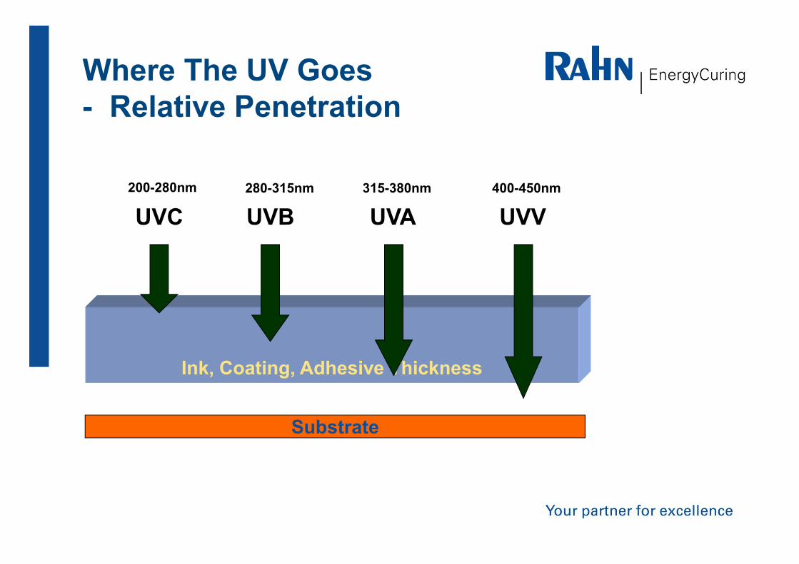
Ink, Coating, Adhesive Thickness
UVC UVB UVA UVV
Substrate
200-280nm 280-315nm 315-380nm 400-450nm
Where The UV Goes - Relative Penetration

Light-Emitting Diodes (LEDs)• LEDs are semiconductor diodes that emit light when an electric current is
applied in the forward direction of the device.
• The output is a form of electroluminescence where incoherent* and narrow-spectrum light is emitted.
• LEDs are usually a small area (less than 1mm-2mm) light source, with optics added on top of the chip to shape the radiation pattern and assist in reflection.
* Electromagnetic radiant energy not all of the same phase, and possibly also consisting of various wavelengths.22

Advantages of UV/LED Technology
Size of 1 LED

SLM Technology
Advantages of SLM (Semiconductor Light Matrix) LEDs:
• Cooler
• More intense
• Longer life
• Precise control
• The full-intensity lifetime of SLM devices is expected to be 15,000+ hours compared to less than 2,000 hours with traditional mercury arc lamps
• Power consumption is typically 30-40% less than that of equivalently-intense Hg lamps, reducing heat generation and total power consumption
• SLM arrays can be constructed to irradiate a wider area more uniformly than traditional Hg lamps, enabling new applications such as web curing of photopolymers using UV SLMs

Energy Efficiency: UV/LED vs. Mercury Lamps
• Barely over 25% of the radiant energy from a conventional arc lamp is useful UV output
• The majority of the energy is “wasted” as visible light (>10%) and heat (>50%)
UV/LED “Power”
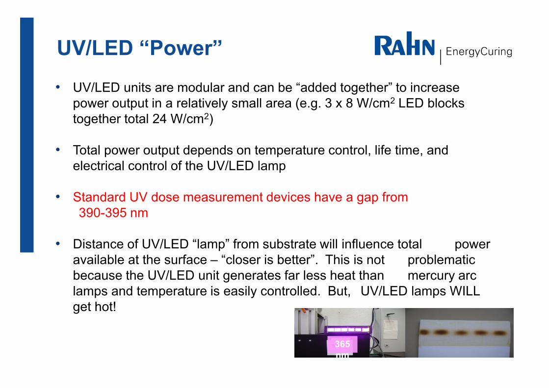
• UV/LED units are modular and can be “added together” to increase power output in a relatively small area (e.g. 3 x 8 W/cm2 LED blocks together total 24 W/cm2)
• Total power output depends on temperature control, life time, and electrical control of the UV/LED lamp
• Standard UV dose measurement devices have a gap from 390-395 nm
• Distance of UV/LED “lamp” from substrate will influence total power available at the surface – “closer is better”. This is not problematic because the UV/LED unit generates far less heat than mercury arc lamps and temperature is easily controlled. But, UV/LED lamps WILL get hot!
365nm
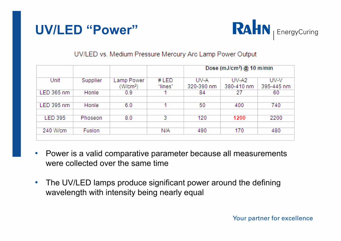
UV/LED “Power”
• Power is a valid comparative parameter because all measurements were collected over the same time
• The UV/LED lamps produce significant power around the defining wavelength with intensity being nearly equal
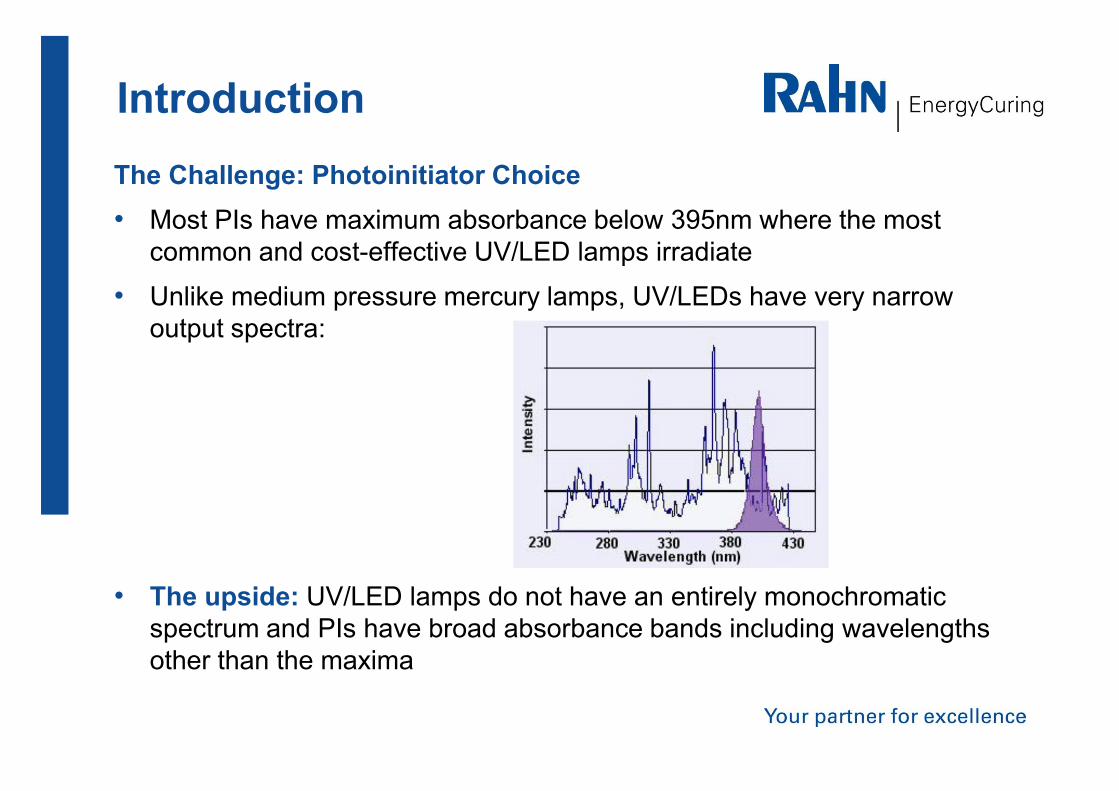
IntroductionThe Challenge: Photoinitiator Choice• Most PIs have maximum absorbance below 395nm where the most
common and cost-effective UV/LED lamps irradiate
• Unlike medium pressure mercury lamps, UV/LEDs have very narrow output spectra:
• The upside: UV/LED lamps do not have an entirely monochromatic spectrum and PIs have broad absorbance bands including wavelengths other than the maxima
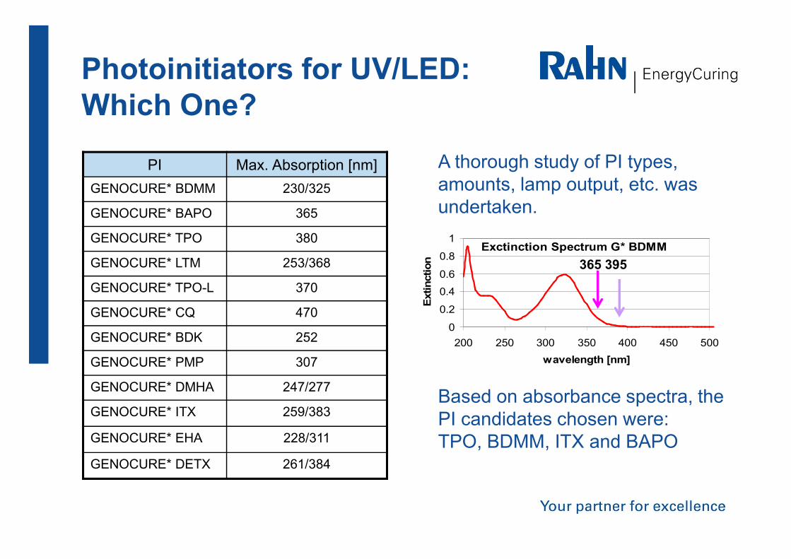
Photoinitiators for UV/LED: Which One?
PI Max. Absorption [nm]GENOCURE* BDMM 230/325
GENOCURE* BAPO 365
GENOCURE* TPO 380
GENOCURE* LTM 253/368
GENOCURE* TPO-L 370
GENOCURE* CQ 470
GENOCURE* BDK 252
GENOCURE* PMP 307
GENOCURE* DMHA 247/277
GENOCURE* ITX 259/383
GENOCURE* EHA 228/311
GENOCURE* DETX 261/384
Exctinction Spectrum G* BDMM
0
0.2
0.4
0.6
0.8
1
200 250 300 350 400 450 500wavelength [nm]
Extin
ctio
n 365 395
Based on absorbance spectra, the PI candidates chosen were:TPO, BDMM, ITX and BAPO
A thorough study of PI types, amounts, lamp output, etc. was undertaken.
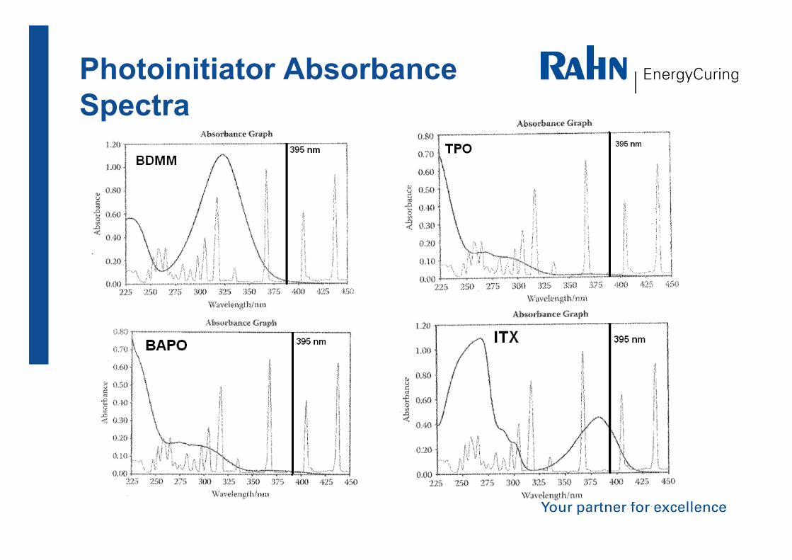
Photoinitiator Absorbance Spectra

• Based on absorbance spectra, ITX>BAPO>TPO>BDMM
• BAPO, TPO >> BDMM with much lower yellowing among Norrish Type I candidates
• ITX (Type II) is very reactive, but too yellow for OPV and whites
• Surface cure is challenging for UV/LED in air
Photoinitiators for UV/LED
The semi-quantitative study with both 365 nm and 395 nm Phoseon water-cooled 8 W/cm2 units concluded the following:

Photoinitiators for UV/LEDA detailed DOE was run in 2011 to fully quantify the results seen in theprevious study. A mixture design with center and axial points on abenchmark CLEAR formulation was tested with a Phoseon 395 nm8W/cm2 variable power, water-cooled curing unit. After all of the numberswere crunched, Type I PI was better than Type II (ITX with MEA) andBAPO was the best PI by far.

Pigment Transmission Spectra
Figures from W. Arthur Green, Industrial Photoinitiators, CRC Press, 2010.
Once pigment is introduced, trends change. Chemistry cannot trump physics: where PI competes for light with pigment, reactivity suffers.
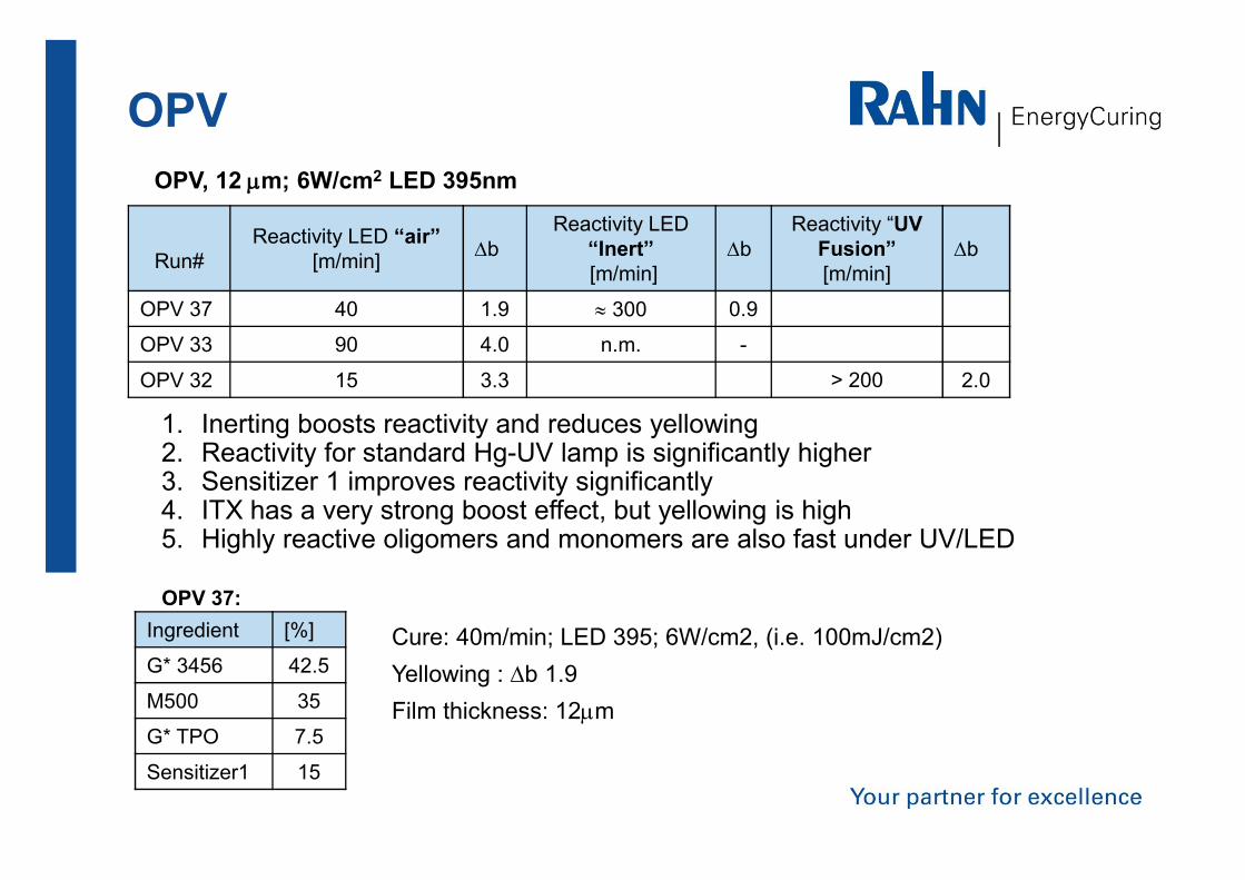
Cure: 40m/min; LED 395; 6W/cm2, (i.e. 100mJ/cm2)Yellowing : ∆b 1.9Film thickness: 12µm
OPV
Ingredient [%]
G* 3456 42.5
M500 35
G* TPO 7.5
Sensitizer1 15
OPV, 12 µm; 6W/cm2 LED 395nm
Run#Reactivity LED “air”
[m/min] ∆bReactivity LED
“Inert”[m/min]
∆bReactivity “UV
Fusion”[m/min]
∆b
OPV 37 40 1.9 ≈ 300 0.9
OPV 33 90 4.0 n.m. -
OPV 32 15 3.3 > 200 2.0
1. Inerting boosts reactivity and reduces yellowing2. Reactivity for standard Hg-UV lamp is significantly higher3. Sensitizer 1 improves reactivity significantly4. ITX has a very strong boost effect, but yellowing is high5. Highly reactive oligomers and monomers are also fast under UV/LED
OPV 37:
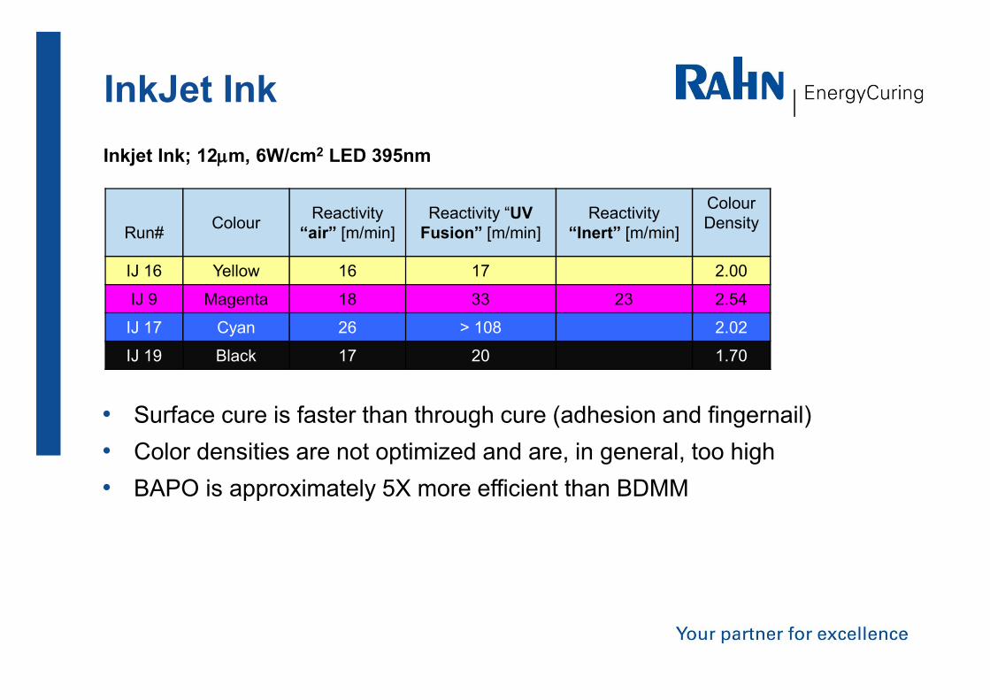
InkJet InkInkjet Ink; 12µm, 6W/cm2 LED 395nm
Run# Colour Reactivity “air” [m/min]
Reactivity “UV Fusion” [m/min]
Reactivity “Inert” [m/min]
ColourDensity
IJ 16 Yellow 16 17 2.00
IJ 9 Magenta 18 33 23 2.54
IJ 17 Cyan 26 > 108 2.02
IJ 19 Black 17 20 1.70
• Surface cure is faster than through cure (adhesion and fingernail)• Color densities are not optimized and are, in general, too high• BAPO is approximately 5X more efficient than BDMM

Flexographic InkFlexographic Ink; 6W/cm2 LED 395nm, app. 1µm,
Run# Colour Reactivity “air”[m/min]
Reactivity “UV Fusion”[m/min]
Colour Density
F27 Yellow 32 > 110 1.55
F31 Magenta 50 > 110 1.52
F29 Cyan 60 > 110 1.86
F36 Black 25 75 1.77
F35 White 35 65 b-value:5.5
• Inerting has no effect in tested black flexographic ink
• Raven Black 1060 shows a higher reactivity than Special Black 250
• Low yellow, opaque white is feasible with some photoinitiator modification
• Short Investigation of LED 395 vs. 365:o Standard photoinitiator cocktail with BDMM with UV/LED 395 6X fastero Standard photoinitiator cocktail with BAPO with UV/LED 395 10X faster

Conclusion• “Fast acrylates” under conventional UV lamps are also fast with UV/LED • Yellowing is problematic for OPV and white, but when the formulation is
optimized a reasonable cure can be realized• Black and Yellow colors are the most difficult to cure• Selection of black pigment is important• Norrish Type II Photoinitiator are effective to achieve good surface cure• Overall system cure speed is optimized by careful selection of
photoinitiators AND acrylate components!
• Starting Point Formulations with competitive cure for OPV, Flexo and Ink Jet Inks are available
Thank you for your attention!