Embed Size (px)
Citation preview

Copyright © 2004, Tjernlund Products, Inc. All rights reserved. P/N 8504125
CPC-3 CONTROLLED START-UP MANUALFOR MODULATING DRAFT & COMBUSTION AIR SYSTEMS
FOR USE WITH AUTO-DRAFT® VSAD-SERIES INDUCERS & VSUB-SERIES BLOWERS
THIS INSTALLATION GUIDE IS INTENDED AS AN AID TO QUALIFIED, LICENSEDSERVICE PERSONNEL FOR PROPER INSTALLATION, ADJUSTMENT ANDOPERATION OF THIS UNIT. READ THESE INSTRUCTIONS THOROUGHLYBEFORE ATTEMPTING INSTALLATION OR OPERATION. FAILURE TO FOLLOWTHESE INSTRUCTIONS MAY RESULT IN IMPROPER INSTALLATION, ADJUST-MENT, SERVICE OR MAINTENANCE POSSIBLY RESULTING IN FIRE, ELECTRI-CAL SHOCK, CARBON MONOXIDE POISONING, EXPLOSION, OR PERSONALINJURY OR PROPERTY DAMAGE.
TJERNLUND PRODUCTS, INC.1601 Ninth Street • White Bear Lake, MN 55110-6794PHONE (800) 255-4208 • (651) 426-2993 • FAX (651) 426-9547Visit our web site • www.tjernlund.com
Listings:The Mechanical Draft System is Listed to UL-378The Mechanical Combustion Air System is Listed to UL-1995

TABLE OF CONTENTS PAGE
DescriptionsInduced Draft / Exhaust ..............................................................................................................................................1Combustion Air............................................................................................................................................................1
Auxiliary Devices ............................................................................................................................................................2Operation Modes
Automatic ....................................................................................................................................................................2Manual.........................................................................................................................................................................2
Suggested Physical Placement of Components & Maximum Lead Lengths ..................................................................3Transducer Sensing Tube Installation .............................................................................................................................3
Induced Draft...............................................................................................................................................................3“Open” Combustion Air................................................................................................................................................3“Sealed” Combustion Air .............................................................................................................................................3
CPC-3 Keypad Layout & Display ...................................................................................................................................4CPC-3 Circuit Board Callouts .....................................................................................................................................5, 6Wiring
Low Voltage VFD Control Cable Wiring to CPC-3......................................................................................................6Low Voltage TD-Series Transducer & PSA-1 Manual Mode Fan Prover Wiring to CPC-3 ........................................7Remote Alarm / Auxiliary Device Wiring .....................................................................................................................7VFD to Inducer / C.A. Blower Wiring ......................................................................................................................8, 9CPC-3 Main Power Input & Heater Interlock Wiring.................................................................................................10Pre-start up Field Wiring Verification.........................................................................................................................10
Start Up of CPC-3Powering & Initializing CPC-3 ...................................................................................................................................10Default CPC-3 Program Settings ..............................................................................................................................11Unlocking & Locking the CPC-3 Keypad...................................................................................................................11Setting CPC-3 Time and Date...................................................................................................................................11Activating the Draft or Combustion Air ......................................................................................................................11
Testing the Operation of System componentsTest Run Set Up........................................................................................................................................................12VFD and Pressure Transducer Response ................................................................................................................12Checking for Proper Rotation....................................................................................................................................12
Draft AdjustmentDraft Set Point Adjustment..................................................................................................................................12, 13Balancing Draft..........................................................................................................................................................13
Combustion Air Adjustment“Open” & “Sealed” Combustion Air Modes of Operation ....................................................................................13, 14Combustion Air Set Point Adjustment .......................................................................................................................14“Open” Mode System Start Up..................................................................................................................................14“Sealed” Mode System Start Up ...............................................................................................................................14
Auxiliary DevicesAlarm Buzzer.............................................................................................................................................................15Aux Sensor Set Up ...................................................................................................................................................15Aux Device Set Up....................................................................................................................................................15
CPC-3 OptionsResetting VFD Drive(s) .............................................................................................................................................15Setting Pressure Units of Measure ...........................................................................................................................15Viewing & Resetting Fault History.............................................................................................................................16Set Stages & Burner Interlock Verification ................................................................................................................16Setting Pre and Post Purge ......................................................................................................................................16
Manual Mode Operation and PSA-1 Fan Prover Switch Adjustment......................................................................16, 17Maintenance & How to Obtain Service Assistance .......................................................................................................17
INDUCED DRAFT EXHAUST & COMBUSTION AIR SYSTEMS
INDUCED DRAFT / EXHAUSTThe automatic variable speed draft system consists of:1. A Draft Inducer (either VSAD-Series or VSUB-Series)2. A CPC-3 Constant Pressure Controller3. A TD-Series Pressure Transducer4. A VFD-Series Variable Frequency Drive5. A PSA-1 Fan Prover for Manual Mode Operation (Included with VSAD & VSUB Series)
COMBUSTION AIR / MAKE-UP AIRThe automatic variable speed combustion air system consists of:1. A VSUB-Series blower2. A CPC-3 Constant Pressure Controller3. A TD-Series Pressure Transducer4. A VFD-Series Variable Frequency Drive5. A PSA-1 Fan Prover for Manual Mode Operation (Included with VSAD & VSUB Series)
1

The Patented CPC-3 Controller can simultaneously control both draft and combustion air so only one is needed when both DraftInducers and Combustion Air Blowers are installed in conjunction with the same heating system. For the remainder of this guideInducer will be synonymous to Induced Draft Exhaust and C.A. Blower will be synonymous to Combustion Air Blower.
AUXILIARY DEVICES
The CPC-3 auxiliary devices include an Audible Alarm Buzzer (circuit board mounted), an Auxiliary Device relay for activating a motor-ized damper in series with the draft and/or combustion function, and a sensor input for a damper end switch. The sensor input canalso be configured to accept a signal from a CO detector and lock out all interlocked burners.
CPC-3 AUTOMATIC / MANUAL MODE SEQUENCES OF OPERATION
CPC-3 AUTOMATIC MODE SEQUENCE OF OPERATION, SEE DIAGRAM A
An aquastat, sequencing control or building management system signals a call for heat. This signal is intercepted and routedthrough the CPC-3.
The CPC-3 compares actual pressure levels in vent connector and/or mechanical room with previously entered set points.
The Inducer speeds up to achieve the vent pressure set point and/or the combustion air blower simultaneously speeds up to achieve desired pressure set point. These separate functions happen in parallel but are based on software and toler-ances unique to the respective draft or combustion air function and to the differential between actual and set point. When the set point is reached the CPC-3 completes the circuit to the heaters allowing ignition sequence to begin.
Pressures are constantly monitored by the transducer during the heating cycle. The Inducer / C.A. Blower motor speeds are independently and continuously adjusted to maintain set points entered into the CPC-3. Winds, outdoor temperatures, natural chimney draft, flue gas temperatures, modulating firing rates and building pressure changes will all be compensated for automatically.
The heaters will be disrupted for 1 minute if at any time the draft cannot be maintained within the times and tolerances of the soft-ware. After this restart delay the CPC-3 will once again try to reach the system set points. If successful, the system will sequence nor-mally. If not successful, the CPC-3 will lock out the heaters until it is manually reset. Up to 5 fault codes will be stored memory.
CPC-3 MANUAL MODE SEQUENCE OF OPERATIONManual Mode is a method of setting Draft and/or Combustion Air at a fixed speed. It was developed to be used in emergency caseswhere a transducer is not operational. In Manual mode, the heaters are allowed to operate as long as the manual mode PSA-1 FanProver Switch is closed. WARNING: Because Manual Mode is a method of setting a fixed speed for Draft and/or Combustion Air, con-sideration must be given to over-drafting and/or excessive combustion air supply, See “Manual Mode Operation and PSA-1 FanProver Switch Adjustment”, page 16. Deactivate heaters not necessary in an emergency situation to reduce the chance for these con-ditions. To shut off heater calls from being processed, refer to the “SET STAGES” option, page 16 or shut off the service switch toeach heater.
4
3
2
1
2
DIAGRAM A

SUGGESTED COMPONENT PHYSICAL PLACEMENT
Although it is not necessary to install the CPC-3 and related VFD(s) adjacent to each other it is highly recommended since both dis-plays may need to be viewed simultaneously during system startup or servicing. A faulted VFD can be reset from either the CPC-3 orthe VFD.
MAXIMUM LEAD LENGTH FROM CPC-3 CONTROLLER:Transducer: 150 feet with 18 AWG (3 leads required)Manual Mode PSA-1 Proving Switch: 325 feet with 18 AWG (2 leads required)VFD Control Signal: 220 feet with 18 AWG (10 leads required)*
*VFD comes with 10 foot set of leads terminated with a VFD quick connect
MAXIMUM LEAD LENGTH FROM VFD TO INDUCER/BLOWER:230 VAC Models: 300 feet with 14 AWG, 600 VAC Insulation460 VAC Models: 100 feet with 14 AWG, 600 VAC insulation
TRANSDUCER SENSING TUBE INSTALLATION
FOR MECHANICAL DRAFT INSTALLATIONSThe TD-2 Transducer sensing tube should be installed inthe cap of a tee or rear of a common manifold. The tee isnecessary so that only static pressure is measured. If thetransducer sensing tube is installed in the side of a ventpipe it will also measure velocity pressure, giving an incor-rect signal back to the CPC-3 Controller. If mounting on theside of the pipe is unavoidable, the sensing tube should beflush to the interior wall of the vent pipe. Typically, draftapplications should sample at a point in back of the ventconnection that is farthest from the inducer/blower, SeeDiagram B.
FOR “SEALED” COMBUSTION AIR APPLICATIONSThe TD-2 Transducer sensing tube should be installed inthe capped end of a common supply manifold. This is nec-essary so that only static pressure is measured. If thetransducer sensing tube is installed in the side of a duct itwill also measure velocity pressure, giving an incorrect sig-nal back to the CPC-3 Controller. If mounting on the side ofthe duct pipe is unavoidable, the sensing tube should beflush to the interior wall of the duct. If a filter is installed itmust be positioned between the blower inlet and intakeopening, See Diagram C.
FOR “OPEN” COMBUSTION AIR APPLICATIONSIn "Open" mode the mechanical room air is sampled and an adjacent space is referenced. Referencing an adjacent space within thebuilding typically provides a more stable reference pressure than referencing outdoor air. In both cases, the goal is to reference staticpressure. Don't sample pressures at locations that can be affected by frequently opened doors, elevator shafts, ventilation fans anddiffusers. The model IPS-1 includes a decorative cover, sampling tube and fittings and when used in conjunction with the TD-3Transducer may be used to sample indoor reference pressure. It reduces the effects of air movement on the sampling tube and pro-vides a finished look. Varying wind speeds will affect outdoor reference pressure and are difficult to neutralize. If sampling outdoor ref-erence pressure, the model WW-1 may be used in conjunction with the TD-3 Transducer to help neutralize the effects of winds. Forbest performance mount the WW-1 at least one foot away from an outside wall
3
D2D
FROM VENTERHEATER FURTHEST
8054004 12/8/04
BACK FROM THE MANIFOLD.BE 2 TIMES THE DIAMETER OF THE PIPE
IF POSSIBLE, THE SENSING TUBE SHOULD
BACK FROM THE LAST HEATER MANIFOLD.BE 2 TIMES THE DIAMETER OF THE PIPE
IF POSSIBLE, THE SENSING TUBE SHOULD2D
FIGURE 8054005 12/9/04
LAST HEATER
FIRST HEATER
COMBUSTION AIR
MANIFOLDCOMBUSTION
AIR INTAKE
INSTALLER-SUPPLIEDFILTRATION MUST BE ON
BLOWER INLET SIDE.
SENSING TUBE
DIAGRAM B
DIAGRAM C

CPC-3 KEYPAD LAYOUT
CPC-3 DISPLAY
4
AUXILIARY DEVICE Green ACTIVATED LEDindicates AUX. CONTROL Relay contacts (C & O)are closed to actuate auxiliary devices such as amotorized louver.
AUXILIARY DEVICE Green SAFETY SWITCHLED indicates Auxiliary device safety contactssuch as a damper end switch are in a closed position within 90 seconds after a call for heat.
Red ALARM LED indicates a system fault isdetected. On board audible alarm buzzer can beactivated. Alarm relay contacts (NO, C & NC) canbe interlocked with building management systemor other device.
CPC-3 Display window
Additional Programming Keys
BURNER STATUSAmber CALL LED indicates burner call for heat Green RUN LED indicates burner approved to fire
after completing CPC-3 safety circuit
POWER SUPPLIESANALOG - 24 VDC CPC-3 on board power supply for check circuits and transducerDIGITAL - 5 VDC CPC-3 on board power supply for CPC-3 microcontroller and logic
COMBUSTION AIR Setup portion of CPC-3 VFD ACTIVATED - Green LED shows VFD turnedon by CPC-3
LIMIT STATUS OK -Green LED shows all limits /safeties closed (i.e. motor or freeze limits)
VFD STATUS OK -Green LED shows VFD is notfaulted, no LED indicates VFD fault
Auto / Manual mode and Setup for Combustion AirOptions
DRAFT Setup portion of CPC-3 VFD ACTIVATED- Green LED shows VFD turnedon by CPC-3
LIMIT STATUS OK - Green LED shows all limits /safeties closed (i.e. motor limit, heat limits, tiltswitches)
VFD STATUS OK - Green LED shows VFD is notfaulted, no LED indicates VFD fault
Auto / Manual mode and Setup for Draft Options
A
B
C
D
E F G H
I
A. The 1st display line is for the Draft System. If the Draft System isnot active, the top line will read "INDUCER INACTIVE" and will not display an operation mode, set point, actual pressure or motor operating speed %.
B. The 2nd display line is for the Combustion Air System. If the Combustion Air System is not active, the second line will read"COMBUS. AIR INACTIVE" and will not display an operation mode, set point, actual pressure or motor operating speed %.
C. The 3rd display line is the "Message" line for different operating phases such as, Start Up, Pre-Purge, Post Purge, Etc. This line also displays faults that have been detected within the overall operation of the control. A fault message displayed will be specific to the fault type, the draft or combustion air system and which operation phase the control was in when the fault occur-red. If the key pad is unlocked, this line converts to a progamma-ble menu line where options are displayed.
D. The 4th and last display line is for the Date and Time. Used when the keypad is unlocked, as a programmable menu options line. In short, when the keypad is unlocked, the bottom 2 lines become menu information lines for the key functions and their options.
E. The 1st column of the display is for the OPERATION MODE and will display an "A" if the Draft or Combustion Air System is active in “Automatic” mode or an "M" if in “Manual” mode.
F. The 2nd column of the display is for the SET POINT of the Draft or Combustion Air system set by the installer. The pressure units displayed (Inches of water column or Pascals) are set under the "Options" key. The factory default set point is -0.15" WC. for Draft and 0.00" WC. for Combustion Air.
G. The 3rd column of the display is for the ACTUAL PRESSURE of the Draft or Combustion Air System, updated every second basedon the pressure sensed by the pressure transducer. If the Draft or Combustion Air System is Active, the Actual Pressure will be displayed 100% of the time. As with the set point, the units of pressure measurement will change based on Inches of WC or Pascals in "Options".
H. The 4th and last column of the display is for the %SPEED of the Draft or Combustion Air System. This speed percentage is directly rendered from the control voltage signal that is being provided by the CPC-3 controller to the VFD. The scale is 1 VDC to 10 VDC.1 VDC = 1% motor speed, 10 VDC = 100% motor speed. Any-time the control is telling the motor to run, the percentage speed is illustrated here.
I. Date and Time display when not used for programming options.

5
MB MC M1 M2 S1 S2 SC S3 D- D+ B R G P1 P2 S2 S1 S2 S1P2P1GRBD+D-S3SCS2S1M2M1MCMB BRGBRGS1S2
OC
S2
S1
12
12
NC
CN
O
NLL N L N L N A B A B A B A B 21 3 4431 2431 2431 2
POWER TERMINALMAIN AC EXP-4E
POWER TERMINALS
HEATER 1 HEATER 2 HEATER 3 HEATER 4
INDUCER PORT COMBUSTION AIR PORT
BOARDALARM
POWERDIGITAL
ANALOG AND
SUPPLIES
KEYPADCONNECTORS
CALLRETURN
JUMPERS
PORTDEVICE
AUXILIARY
PORTALARM
REMOTE
PORTSSIGNALEXP-4E
MICROCONTROLLERS
SWITCHRESET
SELECTOR
INDUCERMOTOR
ROTATION ROTATIONMOTOR
COMBUSTION AIR
SELECTOR
CONTROLLER DISPLAY
DRY1
A24V
A115V
DC
B115V
B24V
DRY2
C115V
C24V
DRY3
D115V
D24V
DRY4
D1 D1 D1 D1
A B
I
C1E
F
H1 G1
H GFUTURE USE FUTURE USE
FUTUREUSE
USEFUTURE
FIGURE 8081005
CPC-3 BOARD CALLOUTS
A) CPC-3 Main Power Switch
B) Power Supply Input Terminals: Accepts either 115 or 230 VAC, 50/60 Hz. 230V power can be suppied from VFD L & L Terminals.
C) Power Supply Output Terminals: Supply power to accessory EXP-4E Expansion boards.
C1) EXP-4E Expansion Modules: Communications connections from EXP-4E Expansion boards.
D) Heater Interlock Terminal Blocks (Four):Positions A & B are for dry contact actuation, with A outputting 5 VDC and B needing 5 VDC to activate the CPC-3. Positions 1 & 2 require either 24 or 115 VAC from a heater control circuit to activate the CPC-3. A factory installed call return jumper wire above each terminal block routes the voltage connected from position 1 to position 3. When the CPC-3 safety circuit is made it switches position 3 to position 4, where the intercepted heater control circuit is routed back to the heater. Positions 3 & 4 are used indepen-dent of positions 1 & 2. If the A & B dry contacts are used to activate the CPC-3 (Call return jumper wire must be removed).
D1) IMPORTANT: Each six position terminal block includes a RED jumper tab to select the heater interlock voltage that is connected heater terminal block. Place RED jumper tab in Dry for positions A & B, 24V or 115V for positions 1 & 2 depening upon heater interlock voltage)
E) Auxiliary Device Terminals:Used to activate a motorized damper/louver in series with the inducer/blower activation by switching power to device through ter-minal C & O. Position S1 outputs 5 VDC to be switched through a damper end switch and returned to position S2. This incorpor-ates the end switch closure into the overall CPC-3 safety circuit. Positions S1 & S2 may also be used to react to the contact clos-ure of a carbon monoxide alarm. The functions of C & O and S1 & S2 are independently activated through the Auxiliary Device key.
F) Remote Alarm Terminals:Used to activate a remote alarm through either normally open or normally closed contacts. A power source is routed to the C posi-tion and returned out of either the N/C or N/O positions if an alarm condition exists.
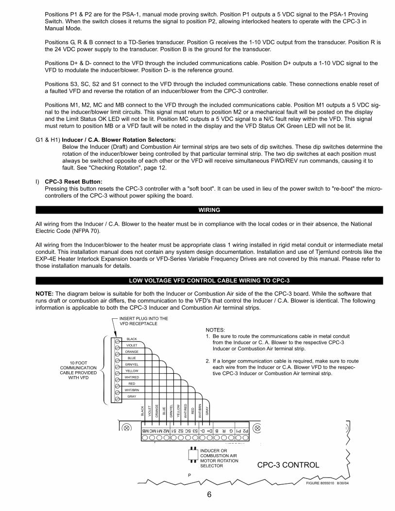
G & H) Draft and Combustion Air Terminals:The CPC-3 can independently control mechanical draft and combustion air inducers/blowers. While the software that runs these functions differs, the communications to the VFD's that control the inducer/blower is identical. The following informationis applicable to both the Inducer and Combustion Air terminal strips.
6
Positions P1 & P2 are for the PSA-1, manual mode proving switch. Position P1 outputs a 5 VDC signal to the PSA-1 Proving Switch. When the switch closes it returns the signal to position P2, allowing interlocked heaters to operate with the CPC-3 in Manual Mode.
Positions G, R & B connect to a TD-Series transducer. Position G receives the 1-10 VDC output from the transducer. Position R is the 24 VDC power supply to the transducer. Position B is the ground for the transducer.
Positions D+ & D- connect to the VFD through the included communications cable. Position D+ outputs a 1-10 VDC signal to the VFD to modulate the inducer/blower. Position D- is the reference ground.
Positions S3, SC, S2 and S1 connect to the VFD through the included communications cable. These connections enable reset of a faulted VFD and reverse the rotation of an inducer/blower from the CPC-3 controller.
Positions M1, M2, MC and MB connect to the VFD through the included communications cable. Position M1 outputs a 5 VDC sig-nal to the inducer/blower limit circuits. This signal must return to position M2 or a mechanical fault will be posted on the display and the Limit Status OK LED will not be lit. Position MC outputs a 5 VDC signal to a N/C fault relay within the VFD. This signal must return to position MB or a VFD fault will be noted in the display and the VFD Status OK Green LED will not be lit.
G1 & H1) Inducer / C.A. Blower Rotation Selectors:Below the Inducer (Draft) and Combustion Air terminal strips are two sets of dip switches. These dip switches determine therotation of the inducer/blower being controlled by that particular terminal strip. The two dip switches at each position must always be switched opposite of each other or the VFD will receive simultaneous FWD/REV run commands, causing it to fault. See "Checking Rotation", page 12.
I) CPC-3 Reset Button:Pressing this button resets the CPC-3 controller with a "soft boot". It can be used in lieu of the power switch to "re-boot" the micro-controllers of the CPC-3 without power spiking the board.
LOW VOLTAGE VFD CONTROL CABLE WIRING TO CPC-3
FIGURE 8055010 8/30/04
D+D-S3SCS2S1M2M1MCMB BRGBRGS1S2
CPC-3 CONTROL
SENSORSAUX. SENSORINDUCER
2 1B R G P1 P2
SELECTOR
INDUCERMOTOR
ROTATION
from the Inducer VFD to the CPC-3 Inducer terminal strip.Be sure to route the communications cable in metal conduit1.
NOTES:
to route each wire from the Inducer VFD to the CPC-3If a longer communication cable is required, make sure2.
Inducer terminal strip correctly. MB to MB, MC to MC, etc.
BLACK
VIOLET
ORANGE
GRN/YEL
BLUE
YELLOW
WHT/RED
RED
WHT/BRN
GRAY
WITH VFD
10 FOOTCOMMUNICATIONCABLE PROVIDED
NOT USED -FOR FUTURE
DEVELOPMENT
NOT USED -FOR FUTURE DEVELOPMENT
THE INDUCERTERMINAL STRIP
INSERT PLUG INTO THE INDUCERVFD RECEPTACLE
GR
AY
WH
T/BR
N
RED
WH
T/R
ED
YELL
OW
GR
N/Y
EL
BLU
E
OR
ANG
E
VIO
LET
BLAC
K
TOP LEFT CORNERCPC-3 CONTROL
BOARD
RS232COM.PORT
NOTE: The diagram below is suitable for both the Inducer or Combustion Air side of the the CPC-3 board. While the software thatruns draft or combustion air differs, the communication to the VFD's that control the Inducer / C.A. Blower is identical. The followinginformation is applicable to both the CPC-3 Inducer and Combustion Air terminal strips.
WIRING
All wiring from the Inducer / C.A. Blower to the heater must be in compliance with the local codes or in their absence, the NationalElectric Code (NFPA 70).
All wiring from the Inducer/blower to the heater must be appropriate class 1 wiring installed in rigid metal conduit or intermediate metalconduit. This installation manual does not contain any system design documentation. Installation and use of Tjernlund controls like theEXP-4E Heater Interlock Expansion boards or VFD-Series Variable Frequency Drives are not covered by this manual. Please refer tothose installation manuals for details.
INDUCER ORCOMBUSTION AIR MOTOR ROTATION SELECTOR
NOTES: 1. Be sure to route the communications cable in metal conduit
from the Inducer or C. A. Blower to the respective CPC-3 Inducer or Combustion Air terminal strip.
2. If a longer communication cable is required, make sure to routeeach wire from the Inducer or C.A. Blower VFD to the respec-tive CPC-3 Inducer or Combustion Air terminal strip.

7
LOW VOLTAGE TD-SERIES TRANSDUCER & PSA-1 MANUAL MODE FAN PROVER WIRING TO CPC-3
MAXIMUM WIRE LENGTH TABLEWARNING:Failure to wire the Transducer
Make sure to wire G - G, R - R
correctly will destroy the
and B - B before activating the
THE INDUCERMANUAL MODE
PRESSURE SWITCHPRESSURE TRANSDUCER
(PSA-1)
THE INDUCER
Transducer!
the CPC-3. TD-___
900' (274m)12 AWG
FIGURE 8055011 9/3/04
D+D-S3SCS2S1M2M1MCMB BRGBRGS1S2
CPC-3 CONTROL
SENSORSAUX. SENSORINDUCER
2 1B R G P1 P2
SELECTOR
INDUCERMOTOR
ROTATION
NOT USED -FOR FUTURE
DEVELOPMENT
NOT USED -FOR FUTURE DEVELOPMENT
THE INDUCERTERMINAL STRIP
TOP LEFT CORNERCPC-3 CONTROL
BOARD
RS232COM.PORT
Wire Gage Max. Distance
600' (183m)14 AWG390' (119m)220' (67m)
16 AWG18 AWG
22 AWG20 AWG
110' (34m)165' (50m)
CAUTION:These wires must be
metal conduit.routed in their own
R B G
NOTE: The diagram below is suitable for both the Inducer or Combustion Air side of the the CPC-3 board. While the software thatruns draft or combustion air differs, the wiring to the Transducer and PSA-1 manual mode fan prover is identical. The following infor-mation is applicable to both the CPC-3 Inducer and Combustion Air terminal strips.
REMOTE ALARM / AUXILIARY DEVICE WIRING
FOR FUTURESYSTEM USE
LOADSYSTEM O.K.
SIGNAL POWER IN
REMOTE ALARMTERMINAL BLOCK
AUXILIARYLOAD
AUXILIARY DEVICEPOWER IN
5 VDC SIGNAL
ALARM AND AUXILIARYRELAY SPECIFICATIONS:
40 AMPS @ 240 VAC / 30 VDC30 AMPS @ 277 VAC
2 HP @ 250 VAC1 HP @ 125 VAC
ALARM RELAY
APPLIANCE 4INTERLOCK BLOCK
USER-PROVIDEDSWITCH
TOP RIGHT CORNERCPC-3 CONTROL BOARD
FOR FUTURESYSTEM USE
OC
S2
S1
12
12
NC
CN
O
3 4
CALLRETURN
JUMPERS
P2 S2 S1 S2 S1
DIGITAL I/O
TJERNLUNDPRODUCTS,
CPC-3
CONTROLAUX.
ALARM
1 2A B4
#3 #4
FOR FUTURESYSTEM USE
SYSTEM FAULTEDLOAD
AUXILIARY SENSINGCIRCUIT
AUXILIARY DEVICETERMINAL BLOCK
NOTE:
INDUCER ORCOMBUSTION AIR MOTOR ROTATION SELECTOR

8
230 VOLT VSAD SERIES WIRING 460 VOLT VSAD SERIES WIRING
plate rating before applying power. Improper supply voltageVerify that the input power voltage matches the VFD's name-
All wiring must be in metal conduit (best) or shielded cable.
the same conduit. Undesired VFD operation could result.Do not run the VFD's input power and output power wiring in
Verify that the venter (VSAD 8/10/12-230) is rated for theoutput voltage from the VFD. If not correct, severe damage to
3.
2.
1.
3.
2.
WARNINGS:
CAUTIONS:
1.
to the VFD could damage the VFD.
the venter and/or the VFD could result.
When the system is completely installed, perform the safetyinterlock and operational test as outlined in the installation
4.
manuals. Failure to do these tests could result in an unsafeand/or incorrectly operating system.
NOTES:
"C" means "Closed Loop""3" means "CPC-3 Control"
3
3
BLACK
VIOLET
ORANGE
GRN/YEL
BLUE
YELLOW
WHT/RED
RED
GRAY
WHT/BRN
VFD COMMUNICATIONS CABLE
ADD
FOR
208-
230
VAC
3Ø
208-
230
VAC
1Ø /
60 H
Z
Route transducer wiring in metal conduit or use Belden ShieldCable #9939 or equivalent. Make sure the transducer wiring does not contain or cross line voltage wiring or undesired
Use caution to ensure that the wiring to the transducer isImproper wiring to the transducer will destroy the transducer.
correct before activating the CPC-3 controller.
transducer performance may result.
4
For vertical termination of the VSAD venter, connect the S2position to the orange wire and cap off the gray wire as shown.
For horizontal termination of the VSAD venter, connect the S2position to the gray wire and cap off the orange wire.
4.
If the provided 10-foot, 10-wire VFD control cable is not long1.enough to meet the application needs, use caution to ensurethat the connections from the VFD to the CPC-3 controllerare correctly located. MB to MB, MC to MC, etc. In addition,
Use caulking to seal the electrical box cover to the electrical2.box, and to seal the conduit holes to hole plugs.
2
reference the Wire Length Table.
If required, non-fused disconnects are to be supplied by the3.installer.
3
FIGURE 8052017 11/18/04
INCLUDED39" (1m) CABLE
BLACK
BLACK
ORANGE
BLUE
GREEN
VIOLET
RED
YELLOW
VSAD MOTOR ENCLOSURE
COOLING FAN
THERMOSTATFAN
GND
VERTICALTILT SWITCH MOTOR
LIMITHIGHLIMIT
L3
L2
L1
GRAY
BLK
BLK
BLK
BLK
BLKBLUE
BLUE
WHT/BRN
HORIZONTALTILT SWITCH
BLK
WEATHERPROOFBOX AND WHIP
MOTOR
Max. length:dedicated metal conduit.
Wiring is to be in
230 VAC SUPPLY / LOAD WIRING
LEGEND:
LOW VOLTAGE / DC CONTROL WIRING
300' (91m) @ 230 VAC
TJERNLUND DRIVE MODELVFD- _ _ _ _ _ _ _ 2C3"2" means "230 VAC"
2
VFDCONTROL
BOX
M1
M2
M3
MG
ND S1 S2 F1 F2
GND
L1 L2/N
L3 NC NC L L
MB
MC
M1
M2
S1
S2
SC
S3
D-
D+
INCLUDED39" (1m) CABLE
BLACK
BLACK
ORANGE
BLUE
GREEN
VIOLET
RED
YELLOW
VSAD MOTOR ENCLOSURE
COOLING FAN
THERMOSTATFAN
GND
VERTICALTILT SWITCH MOTOR
LIMITHIGHLIMIT
L3
L2
L1
GRAY
BLK
BLK
BLK
BLK
BLKBLUE
BLUE
WHT/BRN
HORIZONTALTILT SWITCH
BLK
WEATHERPROOFBOX AND WHIP
MOTOR
Max. length:dedicated metal conduit.
Wiring is to be in
230 VAC SUPPLY / LOAD WIRING
LEGEND:
LOW VOLTAGE / DC CONTROL WIRING
100' (30m) @ 460 VAC
TJERNLUND DRIVE MODELVFD- _ _ _ _ _ _ _ 4C3"4" means "460 VAC"
2
4
VFDCONTROL
BOX
M1
M2
M3
MG
ND S1 S2 F1 F2
GND
L1 L2/N
L3 NC NC L L
MB
MC
M1
M2
S1
S2
SC
S3
D-
D+
460 VAC SUPPLY / LOAD WIRINGplate rating before applying power. Improper supply voltageVerify that the input power voltage matches the VFD's name-
All wiring must be in metal conduit (best) or shielded cable.
Route transducer wiring in metal conduit or use Belden Shield
the same conduit. Undesired VFD operation could result.Do not run the VFD's input power and output power wiring in
Verify that the venter (VSAD 8/10/12-460A) is rated for theoutput voltage from the VFD. If not correct, severe damage to
3.
2.
1.
3.
2.
WARNINGS:
Cable #9939 or equivalent. Make sure the transducer wiring
CAUTIONS:
does not contain or cross line voltage wiring or undesired
Use caution to ensure that the wiring to the transducer isImproper wiring to the transducer will destroy the transducer.1.
correct before activating the CPC-3 controller.
to the VFD could damage the VFD.
the venter and/or the VFD could result.
When the system is completely installed, perform the safetyinterlock and operational test as outlined in the installation
4.
manuals. Failure to do these tests could result in an unsafeand/or incorrectly operating system.
For vertical termination of the VSAD venter, connect the S2position to the orange wire and cap off the gray wire as shown.
For horizontal termination of the VSAD venter, connect the S2position to the gray wire and cap off the orange wire.
4.
NOTES:
If the provided 10-foot, 10-wire VFD control cable is not long1.enough to meet the application needs, use caution to ensurethat the connections from the VFD to the CPC-3 controllerare correctly located. MB to MB, MC to MC, etc. In addition,
"C" means "Closed Loop""3" means "CPC-3 Control"
460 VAC / 3Ø / 60 HZ
3
3
BLACK
VIOLET
ORANGE
GRN/YEL
BLUE
YELLOW
WHT/RED
RED
GRAY
WHT/BRN
transducer performance may result.
Use caulking to seal the electrical box cover to the electrical2.box, and to seal the conduit holes to hole plugs.
2
VFD COMMUNICATIONS CABLE
reference the Wire Length Table.
If required, non-fused disconnects are to be supplied by the3.installer.
3
FIGURE 8052016 11/18/04
VSAD DRAFT INDUCER INTERLOCK WITH VFD
VFD & INDUCER / C.A. BLOWER WIRING
WARNINGS:1. Verify that the input power voltage matches the VFD's nameplate rating before applying power. Incorrect supply voltage can
damage VFD.
2. Verify that the Inducer/Blower is rated for the same voltage as the VFD. Incorrect voltage can damage motor and VFD.
3. Maximum wire lengths between the VFD and the inducer/blower are:230 VAC Models: 300 feet with 14 AWG, 600 VAC Insulation460 VAC Models: 100 feet with 14 AWG, 600 VAC insulation
CAUTIONS:1. All wiring must be in metal conduit.2. Do not route the VFD's input and output wiring in the same conduit. Undesired system operational effects could occur.
NOTES:1. If the provided 10-foot, 10-wire VFD control cable is not long enough, use caution to ensure that the wires from
the VFD control cable are correctly extended. Route in metal conduit. All connections between the VFD and the CPC-3 must alpha/numerically match.MB to MB, MC to MC, etc. See maximum lead length chart to right.
2. Use caulk to seal the exterior electrical box cover and to seal any conduit hole plugs.
3. If required, use only non-fused disconnects.
4. Wire proper Vertical or Horizontal Tilt Switch on VSAD-Series Inducers. For vertical termination of VSAD-Series inducers, connect the S2 position to the Orange wire and cap off the Grey wire. For horizontal terminations of VSAD-Series inducers, connect the S2 position to the Grey wire and cap off the Orange wire.
5. VSUB-Series Blowers are shipped from the factory internally wired for 460 VAC. For 230 VAC applications reconfigure the motor’s internal wiring for 230 VAC by following the diagram on motor label.
6. VSUB-Series Blowers used to provide combustion air must install the FFP-1. The FFP-1 will disable the C. A. Blower when exces-sively hot or cold temperatures are detected in the mechanical room. Refer to FFP-1 instructions for details.
Wire Gage Max. Distance
600' (183m)14 AWG390' (119m)220' (67m)
16 AWG18 AWG
22 AWG20 AWG
110' (34m)165' (50m)
900' (274m)12 AWG
Max. VFD to CPC-3Lead Length

9
VSUB INDUCER OR COMBUSTION AIR BLOWER INTERLOCK WITH VFD
VSUB DRAFT INDUCER INTERLOCK WITH VFD
230 VOLT VSUB DRAFT INDUCER WIRING 460 VOLT VSUB DRAFT INDUCER WIRING
RED
ORANGE
BLUE
GREEN
BLACK
BLACK
BLACK
VSUB BLOWER
TSTATMOTOR HEATER
GROUND
MOTOR LIMIT
MOTOR
Max. length:dedicated metal conduit.
Wiring is to be in
230 VAC SUPPLY / LOAD WIRING
LEGEND:
LOW VOLTAGE / DC CONTROL WIRING
300' (91m) @ 230 VAC
TJERNLUND DRIVE MODELVFD- _ _ _ _ _ _ _ 2C3"2" means "230 VAC"
VFDCONTROL
BOX
M1
M2
M3
MG
ND S1 S2 F1 F2
GND
L1 L2/N
L3 NC NC L L
MB
MC
M1
M2
S1
S2
SC
S3
D-
D+
plate rating before applying power. Improper supply voltageVerify that the input power voltage matches the VFD's name-
All wiring must be in metal conduit (best) or shielded cable.
the same conduit. Undesired VFD operation could result.Do not run the VFD's input power and output power wiring in
Verify that the blower (VSUB 8/12/16/20) is wired for theoutput voltage from the VFD. If not correct, severe damage to
3.
2.
1.
3.
2.
WARNINGS:
CAUTIONS:
1.
to the VFD could damage the VFD.
the blower and/or the VFD could result.
When the system is completely installed, perform the safetyinterlock and operational test as outlined in the installation
4.
manuals. Failure to do these tests could result in an unsafeand/or incorrectly operating system.
"C" means "Closed Loop""3" means "CPC-3 Control"
3
3
BLACK
VIOLET
ORANGE
GRN/YEL
BLUE
YELLOW
WHT/RED
RED
GRAY
WHT/BRN
VFD COMMUNICATIONS CABLE
& 30 WATTS FOR VSUB20)
ARCTIC-DUTYMOTOR HEATER
(15 WATTS FOR VSUB8,12,16
RED
WINDINGSMOTOR
2
ADD
FOR
208-
230
VAC
3Ø
208-
230
VAC
1Ø /
60 H
Z
4 x 4 WEATHERPROOFBOX AND WHIP
2
This blower is shipped from the factory wired for 460 VAC.4.Reconfigure the motor wiring at the motor for 230 VAC.See the Motor Label for details.
4
Route transducer wiring in metal conduit or use Belden ShieldCable #9939 or equivalent. Make sure the transducer wiring does not contain or cross line voltage wiring or undesired
Use caution to ensure that the wiring to the transducer isImproper wiring to the transducer will destroy the transducer.
correct before activating the CPC-3 controller.
transducer performance may result.
INCLUDED CABLE
NOTES:
If the provided 10-foot, 10-wire VFD control cable is not long1.enough to meet the application needs, use caution to ensurethat the connections from the VFD to the CPC-3 controllerare correctly located. MB to MB, MC to MC, etc. In addition,
Use caulking to seal the electrical box cover to the electrical2.box, and to seal the conduit holes to hole plugs.
reference the Wire Length Table.
If required, non-fused disconnects are to be supplied by the3.installer.
3
FIGURE 8052019 11/18/04 460 VAC SUPPLY / LOAD WIRINGplate rating before applying power. Improper supply voltageVerify that the input power voltage matches the VFD's name-
All wiring must be in metal conduit (best) or shielded cable.
the same conduit. Undesired VFD operation could result.Do not run the VFD's input power and output power wiring in
Verify that the blower (VSUB 8/12/16/20) is wired for theoutput voltage from the VFD. If not correct, severe damage to
3.
2.
1.
3.
2.
WARNINGS:
CAUTIONS:
1.
to the VFD could damage the VFD.
the blower and/or the VFD could result.
When the system is completely installed, perform the safetyinterlock and operational test as outlined in the installation
4.
manuals. Failure to do these tests could result in an unsafeand/or incorrectly operating system.
NOTES:
If the provided 10-foot, 10-wire VFD control cable is not long1.enough to meet the application needs, use caution to ensurethat the connections from the VFD to the CPC-3 controllerare correctly located. MB to MB, MC to MC, etc. In addition,
"C" means "Closed Loop""3" means "CPC-3 Control"
460 VAC / 3Ø / 60 HZ
3
RED
ORANGE
BLUE
GREEN
BLACK
BLACK
BLACK
VSUB BLOWER
TSTATMOTOR HEATER
GROUND
MOTOR LIMIT
4 x 4 WEATHERPROOFBOX AND WHIP
MOTOR
Max. length:dedicated metal conduit.
Wiring is to be in
230 VAC SUPPLY / LOAD WIRING
LEGEND:
LOW VOLTAGE / DC CONTROL WIRING
100' (30m) @ 460 VAC
TJERNLUND DRIVE MODELVFD- _ _ _ _ _ _ _ 4C3"4" means "460 VAC"
2
VFDCONTROL
BOX
M1
M2
M3
MG
ND S1 S2 F1 F2
GND
L1 L2/N
L3 NC NC L L
MB
MC
M1
M2
S1
S2
SC
S3
D-
D+
3
BLACK
VIOLET
ORANGE
GRN/YEL
BLUE
YELLOW
WHT/RED
RED
GRAY
WHT/BRN Use caulking to seal the electrical box cover to the electrical2.box, and to seal the conduit holes to hole plugs.
2
VFD COMMUNICATIONS CABLE
reference the Wire Length Table.
& 30 WATTS FOR VSUB20)
ARCTIC-DUTYMOTOR HEATER
(15 WATTS FOR VSUB8,12,16
RED
WINDINGSMOTOR
Route transducer wiring in metal conduit or use Belden ShieldCable #9939 or equivalent. Make sure the transducer wiring does not contain or cross line voltage wiring or undesired
Use caution to ensure that the wiring to the transducer isImproper wiring to the transducer will destroy the transducer.
correct before activating the CPC-3 controller.
transducer performance may result.
INCLUDED CABLE
If required, non-fused disconnects are to be supplied by the3.installer.
3
FIGURE 8052018 11/18/04
230 VOLT VSUB COMBUSTION AIR BLOWER WIRING 460 VOLT VSUB COMBUSTION AIR BLOWER WIRING
plate rating before applying power. Improper supply voltageVerify that the input power voltage matches the VFD's name-
All wiring must be in metal conduit (best) or shielded cable.
the same conduit. Undesired VFD operation could result.Do not run the VFD's input power and output power wiring in
Verify that the blower (VSUB 8/12/16/20) is wired for theoutput voltage from the VFD. If not correct, severe damage to
3.
2.
1.
3.
2.
WARNINGS:
CAUTIONS:
1.
to the VFD could damage the VFD.
the blower and/or the VFD could result.
When the system is completely installed, perform the safetyinterlock and operational test as outlined in the installation
4.
manuals. Failure to do these tests could result in an unsafeand/or incorrectly operating system.
NOTES:
If the provided 10-foot, 10-wire VFD control cable is not long1.enough to meet the application needs, use caution to ensurethat the connections from the VFD to the CPC-3 controllerare correctly located. MB to MB, MC to MC, etc. In addition,
"C" means "Closed Loop""3" means "CPC-3 Control"
3
3
BLACK
VIOLET
ORANGE
GRN/YEL
BLUE
YELLOW
WHT/RED
RED
GRAY
WHT/BRN
RED
ORANGE
BLUE
GREEN
BLACK
BLACK
BLACK
VSUB BLOWER
TSTATMOTOR HEATER
GROUND
MOTOR LIMIT
4 x 4 WEATHERPROOFBOX AND WHIP
FFP-1
Max. length:dedicated metal conduit.
Wiring is to be in
230 VAC SUPPLY / LOAD WIRING
LEGEND:
LOW VOLTAGE / DC CONTROL WIRING
300' (91m) @ 230 VAC
TJERNLUND DRIVE MODELVFD- _ _ _ _ _ _ _ 2C3"2" means "230 VAC"
VFDCONTROL
BOX
M1
M2
M3
MG
ND S1 S2 F1 F2
GND
L1 L2/N
L3 NC NC L L
MB
MC
M1
M2
S1
S2
SC
S3
D-
D+
Use caulking to seal the electrical box cover to the electrical2.box, and to seal the conduit holes to hole plugs.
2
VFD COMMUNICATIONS CABLE
reference the Wire Length Table.
& 30 WATTS FOR VSUB20)
ARCTIC-DUTYMOTOR HEATER
(15 WATTS FOR VSUB8,12,16
RED
WINDINGSMOTOR
Route transducer wiring in metal conduit or use Belden ShieldCable #9939 or equivalent. Make sure the transducer wiring does not contain or cross line voltage wiring or undesired
Use caution to ensure that the wiring to the transducer isImproper wiring to the transducer will destroy the transducer.
correct before activating the CPC-3 controller.
transducer performance may result.
The FFP-1 will disable the combustion air blower when5.excessively hot or cold room air is detected. Refer to theFFP-1 installation instructions for details.
REFER TO FFP-1 INSTALLATIONINSTRUCTIONS FOR DETAILS
HEAT LIMIT FREEZE LIMIT
5
This blower is shipped from the factory wired for 460 VAC.4.Reconfigure the motor wiring at the motor for 230 VAC.See the Motor Label for details.
2 ADD
FOR
208-
230
VAC
MOTOR4
INCLUDED CABLE
3
FIGURE 8052021 11/18/04
8052
021
SH
EET
2
If required, non-fused disconnects are to be supplied by the3.installer.
208-
230
VAC
3Ø
1Ø /
60 H
Z
460 VAC SUPPLY / LOAD WIRINGplate rating before applying power. Improper supply voltageVerify that the input power voltage matches the VFD's name-
All wiring must be in metal conduit (best) or shielded cable.
the same conduit. Undesired VFD operation could result.Do not run the VFD's input power and output power wiring in
Verify that the blower (VSUB 8/12/16/20) is wired for theoutput voltage from the VFD. If not correct, severe damage to
3.
2.
1.
3.
2.
WARNINGS:
CAUTIONS:
1.
to the VFD could damage the VFD.
the blower and/or the VFD could result.
When the system is completely installed, perform the safetyinterlock and operational test as outlined in the installation
4.
manuals. Failure to do these tests could result in an unsafeand/or incorrectly operating system.
NOTES:
If the provided 10-foot, 10-wire VFD control cable is not long1.enough to meet the application needs, use caution to ensurethat the connections from the VFD to the CPC-3 controllerare correctly located. MB to MB, MC to MC, etc. In addition,
"C" means "Closed Loop""3" means "CPC-3 Control"
460 VAC / 3Ø / 60 HZ
3
230 VAC SUPPLY / LOAD WIRING
LEGEND:
LOW VOLTAGE / DC CONTROL WIRING
100' (30m) @ 460 VAC
TJERNLUND DRIVE MODELVFD- _ _ _ _ _ _ _ 4C3"4" means "460 VAC"
2
VFDCONTROL
BOX
M1
M2
M3
MG
ND S1 S2 F1 F2
GND
L1 L2/N
L3 NC NC L L
MB
MC
M1
M2
S1
S2
SC
S3
D-
D+
3
BLACK
VIOLET
ORANGE
GRN/YEL
BLUE
YELLOW
WHT/RED
RED
GRAY
WHT/BRN Use caulking to seal the electrical box cover to the electrical2.box, and to seal the conduit holes to hole plugs.
2
VFD COMMUNICATIONS CABLE
reference the Wire Length Table.
& 30 WATTS FOR VSUB20)
ARCTIC-DUTYMOTOR HEATER
(15 WATTS FOR VSUB8,12,16
RED
WINDINGSMOTOR
Route transducer wiring in metal conduit or use Belden ShieldCable #9939 or equivalent. Make sure the transducer wiring does not contain or cross line voltage wiring or undesired
Use caution to ensure that the wiring to the transducer isImproper wiring to the transducer will destroy the transducer.
correct before activating the CPC-3 controller.
transducer performance may result.
The FFP-1 will disable the combustion air blower when4.excessively hot or cold room air is detected. Refer to theFFP-1 installation instructions for details.
REFER TO FFP-1 INSTALLATIONINSTRUCTIONS FOR DETAILS
HEAT LIMIT FREEZE LIMIT
4
MOTOR
INCLUDED CABLE
If required, non-fused disconnects are to be supplied by the3.installer.
3
FIGURE 8052020 11/18/04
RED
ORANGE
BLUE
GREEN
BLACK
BLACK
BLACK
VSUB BLOWER
TSTATMOTOR HEATER
GROUND
MOTOR LIMIT
4 x 4 WEATHERPROOFBOX AND WHIP
FFP-1
Max. length:dedicated metal conduit.
Wiring is to be in

PRE-START UP FIELD WIRING VERIFICATION
The CPC-3 has two sets of terminal strips across the top of its circuit board. All mechanical draft related connections are made on the"INDUCER" terminal strip located on the top left side of the circuit board. All mechanical combustion air related connections are madeon the "COMBUSTION AIR" terminal strip located on the top right side of the circuit board. IMPORTANT: It is critical that wiring con-nections below are correct.
1. Verify Transducer connections (Red terminal blocks of Inducer or Combustion Air terminal strip) G, R & B are wired to the corresponding letter on the TD-Series transducer terminal strip. Failure to maintain proper polarity may damage transducer. IMPORTANT: These wire leads must be enclosed within dedicated metal conduit. Do not run any other power leads in the same conduit or share a junction box with any other leads.
2. The inducer or combustion air manual mode proving switch, model PSA-1 should be connected to terminals P1 and P2 of the Inducer or Combustion Air terminal strip. These leads may share conduit with other circuits within the mechanical room.
3. The free end of the CPC-3/VFD communications cable should be wired to the blue, black and green terminal blocks of the CPC-3 inducer or combustion air terminal strip. It is critical that the colored leads be connected to the exact terminals as depicted on the wiring schematic. If the cable has been extended in the field wire labels should have been affixed indicating the terminal block des-ignations. IMPORTANT: These wire leads must be enclosed within dedicated metal conduit. Do not run any other power leads in the same conduit or share a junction box with any other leads.
START UP OF VSAD-SERIES AND VSUB-SERIES VARIABLE SPEED SYSTEMS WITH THE CPC-3
POWERING UP THE CPC-3Switch the Power switch on lower left of board to the left. After a brief moment, the display will come on and display will read "CPC-3CPC-3" on all 4 lines. This indicates that the CPC-3 is functioning and going through it's power-up routine.
INITIALIZING & PROGRAM SETTINGSWhen the CPC-3 is powered up, it retrieves the saved system settings from memory and loads them into the program. During the ini-tializing process, the control will display the saved system settings as well as other useful information.
10
CPC-3 MAIN POWER INPUT WIRING & HEATER INTERLOCK WIRING
FIGURE 8055017
CPC-3 POWER SUPPLY WIRING
SUPPLY POWER HERE FROM A TJERNLUND VFD,"L" AND "L" TERMINALS, OR FROM ANOTHER
GROUND LUGWITH NUT
NLL N L N L N
POWER INPUTMAIN AC EXP-4E
POWER OUTPUT TERMINALS HEATER 1
POWERDIGITAL
ANALOG AND
SUPPLIES
3 41 2A B3 41 2A B
AC POWERMAIN
ON
OF
F
#1 #2
TERMINAL INTERLOCK
CPC-3 MAIN POWER SPECIFICATIONS:
THE CPC-3 HAS BUILT-IN CIRCUIT PROTECTION.
12/10/04
ON / OFFSWITCH
DRY1
A24V
A115V B115V
B24V
DRY2
OR
24 VAC
OR
115 VAC
OR
230 VAC
OR
CALL METHOD"DRY"
CALL HOT NEUTRAL
CALL METHOD"VOLTAGE"
22
3
RELAYSAFETY
RELAYSAFETY
BLOCKWIRE ANY ADDITIONALREQUIRED INTERLOCKBLOCKS THE SAME ASTHE HEATER 1 INTER-
LOCK BLOCK.
HEATER 2INTERLOCK
BLOCK
0.50 AMP MAXIMUM @ 95-265 VAC.
120 / 208-230 VAC POWER SOURCE.
INTERLOCKEDHEATER
RUN SIGNAL
CALL VOLTAGE FROM INTERLOCKEDHEATER CONTROL CIRCUIT
USER-PROVIDEDCALL SWITCH
WIRECALL
JUMPER
WIRECALL
JUMPER
11
HEATER INTERLOCKCALL METHODS
If using the “Dry” call method,place the RED jumper tab inthe “DRY” position. Remove theWire Call Jumper that routesvoltage from terminal 1 to 3.
If using the “Voltage CallMethod”, place the RED jumpertab in either the 24V or 115Vposition depending upon heaterinterlock voltage.
The Wire Call Jumper routesthe “voltage” hot call signalform the #1 position to the #3position. When the CPC-3 safe-ty relay closes, this voltage isrouted to position #4 and theinterlocked burner.
If activating the CPC-3 with adifferent call voltage than thatof the interlocked burner runsignal, remove the Wire CallJumper and provide the con-trolled voltage to position #3.

11
The Factory Default Settings for the CPC-3 are as follows:
FACTORY DEFAULTSoftware Version: XX.XX.XXPressure Unit Variables: Inches of Water ColumnPre-Purge Time Setting: 0 Minutes, 0 SecondsPost Purge Time Units: 0 Minutes, 0 SecondsFault History: No FaultsAuxiliary Device Options:
Alarm Buzzer: OffAuxiliary Sensor Type: NoneAuxiliary Device Type: None
Induced Draft Condition: InactiveCombustion Air Condition: InactiveHeater Set Stages: All On
Once the settings have loaded, the initializing process is complete. The control is now ready to be set for operation.
UNLOCKING AND LOCKING THE KEYPADNo Settings within the CPC-3 Control can be changed until the keypad is unlocked. This safety feature keeps unauthorized personnelfrom changing settings. Any key that is pressed while the Key Pad is Locked will result in a “!! KEY PAD LOCKED !!” message.
Unlocking and Locking the Keypad To unlock the keypad, press the SAVE SETTING Key for 5 seconds. When the keypad isunlocked, the “!! KEY PAD LOCKED !!” message on the bottom line of the display will change to “….KEY PAD OPEN….” with the KeyPad Open, settings can be adjusted. If the Inducer and Combustion Air are inactive as indicated by the first 2 lines of the display, onlythe TIME / DATE, AUXILIARY DEVICE, and OPTIONS settings will be adjustable. The SET POINT, PRE-PURGE, and POSTPURGE settings are specific to the Draft Inducer and / or Combustion Blower operation and will not be available until the Inducer and/ or Combustion Air systems have been activated, See “Activating the Draft or Combustion Air” below.
To unlock the keypad, press the SAVE SETTING Key for 5 seconds.The keypad can be locked any time the "Keypad Open" message is displayed by pressing the ENTER key and then pressing SAVESETTING. The keypad stays open for 30 minutes after the last key is pressed and then automatically locks.
SETTING TIME AND DATEWith the keypad unlocked, press the TIME / DATE key. NOTE: The "month" is displayed on the right side of the 3rd line of the display.This is the time / date parameter that is ready to be adjusted. Pressing the ENTER key will toggle the adjustable time / date settings.To change any of the month, day, year, hour, minute, and am/pm settings press the ENTER key until the parameter to adjust is shownon the display and use the INCREASE and DECREASE keys to adjust. Press the ENTER key until the next desired parameter is dis-played and again use the INCREASE and DECREASE keys to adjust. Once all of the time / date settings have been adjusted, pressthe SAVE SETTING key to save. To exit the Time / Date screen, press the TIME / DATE key. NOTE: Any time power is removed fromthe control, the time / date settings will need to be reset.
ACTIVATING THE DRAFT OR COMBUSTION AIRTo activate the Draft or Combustion Air the keypad must be unlocked. Press the SET UP key under the appropriate side (Draft orCombustion Air) of the CPC-3 keypad. The display text will indicate that you are in the Set Up mode. All functions and settings can beset while the SETUP is open and the Draft or Combustion Air function is active. Pressing the SAVE SETTING key will activate theDraft or Combustion Air portion of the CPC-3 control.
The top line of the display has been assigned to the Draft information. The second line of the display has been assigned to theCombustion Air information. With either the Draft or Combustion Air portion active, and in “AUTOMATIC” mode reading from left toright an (“A” will be displayed in the first column under either the 1st line Draft or 2nd line Combustion Air). The CPC-3 will self regu-late the speed of the Inducer / C.A. Blower to equal the CPC-3 set point(s) when a call for heat is recognized.
If the AUTO / MANUAL key is pressed while setup is active, the Inducer / C.A. Blower will be in the “MANUAL” mode (“M” will be dis-played in the first column under either the 1st line Draft or 2nd line Combustion Air). The CPC-3 will run the fan at a constant speedthat is set manually by the user. WARNING: Because Manual Mode is a method of setting a fixed speed for Draft and/or CombustionAir, consideration must be given to over-drafting and/or excessive combustion air supply, See “Manual Mode of Operation and PSA-1Fan Prover Switch Adjustment”, page 16.
Next piece to the right on the display is the SET POINT. This is the pressure value that is used by the CPC-3 when in the“AUTOMATIC” mode. Further right is the ACTUAL PRESSURE. This is the vent pressure as sensed by the pressure transducer. Thelast information on the display is the % SPEED that the Inducer / C.A. Blower is operating at. To deactivate the Inducer / C.A. Blowerpress the SAVE SETTING key again. NOTE: All settings made while in setup and saved will be defaulted when the Inducer / C.A.Blower is made active.
Press the SET UP key under the Draft or the Combustion Air side of the CPC-3 keypad.Press the SAVE SETTING key to activate the Draft or the Combustion air portion of the CPC-3 control.

TESTING THE OPERATION OF THE SYSTEM COMPONENTS
TEST RUN SET UPTest run can be used to test several aspects of the Inducer / C.A. Blower. While in Test Run mode, the communication between theCPC-3 control and the VFD can be confirmed, a response from the pressure transducer can be confirmed and the Inducer / C.A.Blower rotation can be checked and reversed if necessary. Test Run can not be operational while a heater call is recognized by theCPC-3 control. To operate Test Run, make sure all interlocked heater calls have been removed or refer to the SET STAGES, page 15to lock out heater calls from being processed.
Test Run is a manually driven test where the user adjusts the speed of the Inducer / C.A. Blower. In order to perform Test Run, theKey Pad must be unlocked and the Set Up menu for Draft or Combustion Air must be open. Press the INCREASE key until "TESTRUN OFF" appears in the bottom line of the display. To activate test run, press the ENTER key. Note that the Test Run messagechanged to "TEST RUN ON". The factory default setting for test run is 0%. Using the INCREASE key, adjust the Test Run percentageto 50%.
Press the SET UP key under the Draft or Combustion Air side of the CPC-3 keypad to open SET UP menu.Press the INCREASE key until "TEST RUN OFF" appears in the bottom line of the display.Press the ENTER key to change display to "TEST RUN ON".Press the INCREASE key, adjust the Test Run percentage to 50%.
VFD RESPONSEWith the control in Test Run and operating at 50%, the VFD should be displaying an output frequency and the Inducer / C.A. Blowershould be running. If no response from the VFD or the Inducer / C.A. Blower is realized, verify that the VFD ACTIVATED LED is solidGreen, the VFD has not faulted (solid red ALARM LED if faulted) and that the VFD has supply power at the correct voltage.
PRESSURE RESPONSEWhile in Test Run, the Actual Pressure displayed on 3rd column of CPC-3 should be a negative pressure. Increasing the Test Run %should increase this negative value. Decreasing the Test Run % should decrease the negative. If the pressure does not change,check the wiring between the control and the pressure transducer, verify the transducer is pneumatically connected to the vent pipemanifold and the front fitting on the transducer, and check to make sure the pressure transducer is operating correctly.
CHECKING ROTATIONWhile in Test Run and operating at 50%, record the Actual Pressure displayed on the top line ofthe display_______. Press the ENTER key to shut off the Test Run option and wait 60 seconds.Open the door to the CPC-3 control and reference the 2 dip switches under the Inducer orCombustion Air terminal blocks at the top of the circuit board. These switches are used to reversethe rotation of the Inducer / C.A. Blower. Switch both switches on the appropriate Inducer orCombustion Air side to the opposite position they are currently in. Close the cover to the controland activate Test Run again by pressing the ENTER key. Remember that no heater can be callingfor heat while performing this test. Adjust the Inducer / C.A. Blower speed to 50% again and recordthe Actual Pressure displayed_______. The test that resulted in the greatest negative pressure isthe correct rotation. If the second half of the test resulted in a lower negative pressure the rotationwill need to be reversed to the original condition. Press ENTER to shut off the Test Run, wait 60seconds, and reverse the 2 dip switch settings.
CAUTION: Systems that use multiple VFD's and/or multiple Inducers / C.A. Blowers will need tovisually verify each fan’s rotation. Changing the rotation as described above will change the rota-tion of all connected VFD's and fans. In multiple configurations, some rotations may be correctwhile others may not. Switch any 2 of the 3 motor leads of the offending Inducer / C.A. Blower tochange the direction of its rotation. VSAD Series impellers must rotate counter-clockwise asviewed through the discharge grill. VSUB Series impellers must rotate counter-clockwise as viewedfrom the end bell/cooling fan of the motor. Failure to insure correct rotation may result in higherpower usage and significantly reduced inducer/blower performance.
Press the ENTER key to shut off the Test Run option and wait 60 seconds.
Change rotation dip switches as described above.
Press ENTER key to activate new Test Run, press Increase key to adjust Inducer / C.A. Blowerspeed to 50% and record the Actual Pressure as displayed on the top line of the display.
The test that resulted in the greatest negative pressure is the correct rotation. If the second half of the test resulted in a lower nega-tive pressure the rotation will need to be reversed to the original condition by changing the dip switches to the opposite positions.
ADJUSTING DRAFTReference the heater manufacturer's instructions for its specified draft range and for where the draft should be sampled. In generalmost heaters will operate efficiently with a draft of -0.02 to -0.05" w.c. measured in the vent riser between the flue outlet and baromet-ric draft control (if present). The CPC-3 has a default draft set point of -0.15" w.c. This vent manifold pressure may need to be adjust-ed up or down to meet the draft requirements of the interlocked heating equipment.
12
VSUB ROTATION 2/27/04
I MP
EL
LER
ROTATI
ON
VSAD-SERIES ROTATION
VSUB-SERIES ROTATION
13
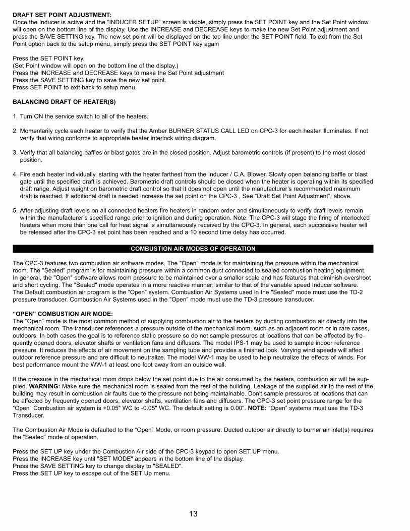
DRAFT SET POINT ADJUSTMENT:Once the Inducer is active and the “INDUCER SETUP” screen is visible, simply press the SET POINT key and the Set Point windowwill open on the bottom line of the display. Use the INCREASE and DECREASE keys to make the new Set Point adjustment andpress the SAVE SETTING key. The new set point will be displayed on the top line under the SET POINT field. To exit from the SetPoint option back to the setup menu, simply press the SET POINT key again
Press the SET POINT key.(Set Point window will open on the bottom line of the display.)Press the INCREASE and DECREASE keys to make the Set Point adjustmentPress the SAVE SETTING key to save the new set point.Press SET POINT to exit back to setup menu.
BALANCING DRAFT OF HEATER(S)
1. Turn ON the service switch to all of the heaters.
2. Momentarily cycle each heater to verify that the Amber BURNER STATUS CALL LED on CPC-3 for each heater illuminates. If not verify that wiring conforms to appropriate heater interlock wiring diagram.
3. Verify that all balancing baffles or blast gates are in the closed position. Adjust barometric controls (if present) to the most closed position.
4. Fire each heater individually, starting with the heater farthest from the Inducer / C.A. Blower. Slowly open balancing baffle or blast gate until the specified draft is achieved. Barometric draft controls should be closed when the heater is operating within its specifieddraft range. Adjust weight on barometric draft control so that it does not open until the manufacturer’s recommended maximum draft is reached. If additional draft is needed increase the set point on the CPC-3 , See “Draft Set Point Adjustment”, above.
5. After adjusting draft levels on all connected heaters fire heaters in random order and simultaneously to verify draft levels remain within the manufacturer’s specified range prior to ignition and during operation. Note: The CPC-3 will stage the firing of interlocked heaters when more than one call for heat signal is simultaneously received by the CPC-3. In general, each successive heater will be released after the CPC-3 set point has been reached and a 10 second time delay has occurred.
COMBUSTION AIR MODES OF OPERATION
The CPC-3 features two combustion air software modes. The "Open" mode is for maintaining the pressure within the mechanicalroom. The "Sealed" program is for maintaining pressure within a common duct connected to sealed combustion heating equipment.In general, the "Open" software allows room pressure to be maintained over a smaller scale and has features that diminish overshootand short cycling. The "Sealed" mode operates in a more reactive manner; similar to that of the variable speed Inducer software.The Default combustion air program is the “Open” system. Combustion Air Systems used in the "Sealed" mode must use the TD-2pressure transducer. Combustion Air Systems used in the "Open" mode must use the TD-3 pressure transducer.
“OPEN” COMBUSTION AIR MODE:The “Open” mode is the most common method of supplying combustion air to the heaters by ducting combustion air directly into themechanical room. The transducer references a pressure outside of the mechanical room, such as an adjacent room or in rare cases,outdoors. In both cases the goal is to reference static pressure so do not sample pressures at locations that can be affected by fre-quently opened doors, elevator shafts or ventilation fans and diffusers. The model IPS-1 may be used to sample indoor referencepressure. It reduces the effects of air movement on the sampling tube and provides a finished look. Varying wind speeds will affectoutdoor reference pressure and are difficult to neutralize. The model WW-1 may be used to help neutralize the effects of winds. Forbest performance mount the WW-1 at least one foot away from an outside wall.
If the pressure in the mechanical room drops below the set point due to the air consumed by the heaters, combustion air will be sup-plied. WARNING: Make sure the mechanical room is sealed from the rest of the building. Leakage of the supplied air to the rest of thebuilding may result in combustion air faults due to the pressure not being maintainable. Don't sample pressures at locations that canbe affected by frequently opened doors, elevator shafts, ventilation fans and diffusers. The CPC-3 set point pressure range for the“Open” Combustion air system is +0.05" WC to -0.05" WC. The default setting is 0.00". NOTE: “Open” systems must use the TD-3Transducer.
The Combustion Air Mode is defaulted to the “Open” Mode, or room pressure. Ducted outdoor air directly to burner air inlet(s) requiresthe “Sealed” mode of operation.
Press the SET UP key under the Combustion Air side of the CPC-3 keypad to open SET UP menu.Press the INCREASE key until "SET MODE" appears in the bottom line of the display.Press the SAVE SETTING key to change display to "SEALED".Press the SET UP key to escape out of the SET Up menu.
“SEALED” COMBUSTION AIR MODE:The “Sealed” mode supplies combustion air to a Combustion Air Manifold. Heaters with a combustion air inlet collar may be connect-ed to a Combustion Air Manifold. The pressure is measured between the manifold and the mechanical room space. As heaters con-sume combustion air from the manifold, the “Sealed” mode recognizes the negative pressure and communicates to the CombustionAir Blower to provide Combustion Air. The CPC-3 Set Point pressure range for the Sealed mode is +0.05" WC to -0.50" WC. Thedefault setting is 0.00" WC. NOTE: “Sealed” systems must use the TD-2 Transducer.
COMBUSTION AIR SET POINT: Once the Combustion Air is active and the COMBUSTION AIR SETUP screen is visible, press theSET POINT key and the Set Point window will open on the bottom line of the display. Use the INCREASE and DECREASE keys tomake the Set Point adjustment and press the SAVE SETTING key to save. The new set point will be displayed on the second lineunder the SET POINT field. To exit from the Set Point option back to the setup menu, press the SET POINT key again. WARNING:The SET POINT pressure is the reference pressure the control will maintain the system static pressure at. Make sure an acceptablestatic pressure is defined and used. Make sure to test fire each heater and all combination of heaters while monitoring the draft pres-sure at each heater. In most cases, a Combustion Air Set Point of 0.00" is acceptable. Make sure the reference side of the PressureTransducer is in a non-turbulent area and is an acceptable reference area outside of the Mechanical Room. Tjernlund Products, Inc. isnot responsible for a Set Point pressure that results in misapplied Combustion Air pressures to the heaters, mechanical room, or anyother location that could cause damage. If needed, consult Tjernlund Products, Inc. for more details.
"OPEN" COMBUSTION AIR MODE SYSTEM START-UP
Mechanical room pressure CPC-3 set points are +0.05 to -0.05” WC. If a positive pressure set point is desired extra care must betaken to insure that the mechanical room is tightly sealed to outside spaces. Based on mechanical room size and leakage factor C.A.Blower performance may not be adequate unless a positive pressure set point was factored into original computations.
1. Turn ON the service switch to all of the heaters.
2. Momentarily cycle each heater to verify that its CPC-3 Amber CALL LED illuminates. If not, verify that wiring conforms to appropri-ate heater interlock wiring diagram.
3. Close all doors and roof hatches within the mechanical room. Activate all exhaust fans and any other air consuming devices within the mechanical room. Fire all heaters. VERIFY: A) The draft for each heater is within the heater manufacturer’s specified range. If barometric draft controls are used they should be mostly closed when the heater is operating within its specified draft range. Adjust weight on barometric draft control if necessary. B) That the VFD has not reached the factory set maximum hertz output. Reference VFD installation instructions for maximum hertz output. If the VFD tops out with all heaters firing the probable cause is excessive air leakage to connected spaces.
4. Verify draft levels on all connected heaters. Fire heaters in random order and simultaneously to ensure that draft levels remain within the specified range. Note: The CPC-3 will stage the firing of interlocked heaters when more than one call for heat signal is simultaneously received. In general, each successive heater will be released after the CPC-3 set point has been reached and a 10-second time delay has occurred.
"SEALED" COMBUSTION AIR MODE SYSTEM START-UP
Duct pressure set points are +0.15 to -0.60 inches water column. The sensing tube for the TD-2 transducer should be installed afterthe outlet of the VSUB-Series blower. The set point is not critical, as long as it can produce a neutral pressure in each individualheater’s duct connection. Balancing baffles should be installed in each individual branch duct if the combustion air duct is directly con-nected to more than one heater. Care should be taken not to create a positive pressure near the heater’s supply duct connectionbecause it may cause the heater’s internal draft inducer to draw excessive amperage.
1. Turn ON the service switch to all of the heaters.
2. Momentarily cycle each heater to verify that its corresponding CPC-3 Amber LED illuminates. If not, verify that wiring conforms to appropriate heater interlock wiring diagram.
3. Verify that all balancing baffles are in the closed position. Fire each heater individually, starting with the heater farthest from the VSUB blower. Slowly open balancing baffle until a neutral pressure is measured in the branch duct serving that heater. Measure pressure on the heater’s side of the balancing baffle.
4. After adjusting the pressures on all connected heaters, fire each in random order and simultaneously to verify that pressure levels remain at or near neutral. NOTE: The CPC-3 will stage the firing of interlocked heaters when more than one call for heat signal is simultaneously received. In general, each successive heater will be released after the CPC-3 set point has been reached and a 10 second time delay has occurred.
14

15
AUXILIARY DEVICES
The CPC-3 Auxiliary Devices include an Audible Alarm Buzzer (on the board), an Auxiliary Sensor Circuit (Blue terminal S1 and S2)and Auxiliary Device Relay (Green terminal C and O). Due to the different ways a relay and a sensor can be used, auxiliary deviceoptions have been created with specific applications in mind. To set any of the auxiliary devices, the Key Pad must first be unlocked.With the key pad unlocked, press the AUXILIARY DEVICE key. Use the INCREASE and DECREASE to scroll through the availableoptions. Once at the desired option, press the ENTER key to enter the desired option. Using the INCREASE and DECREASE keyswill scroll through the available menu in each option. Press the SAVE SETTING key to change any option. To exit the Auxiliary DeviceMenu, press the AUXILIARY DEVICE key. Each programmable option is described in detail below.
ALARM BUZZERPressing the SAVE SETTING key will change whether this option is "On" or "Off". If the alarm buzzer is "On", the board-mountedbuzzer will sound anytime the CPC-3 control detects a System Fault. NOTE: The on-board Alarm relay will change state during aSystem Fault regardless of the condition of the alarm buzzer. The factory default setting for the alarm buzzer is “Off”.
AUX SENSOR SETUPThere are 3 programmable conditions for the Auxiliary Sensor. To view these 3 options, press the ENTER key to enter the AuxSensor menu. Once the Enter Key is pressed, the bottom line becomes active and will display the current setting. To change thisoption, use the INCREASE and DECREASE keys to scroll through the available options. When the desired option is visible, press theSAVE SETTING key to save the option. The available Sensor options are listed below.
NONE: With "None" selected, the Auxiliary sensor is turned off and is not used by the CPC-3 control. This is the factory default settingfor the Auxiliary Sensor.
COMB. LOUVERThis sensor option is to be used with a switch that is sensed closed after a call for heat is established to the CPC-3 control. Once acall for heat is recognized, the sensor circuit is given 90 seconds to close. This option is often used with Motorized Combustion AirLouvers that include an end switch. The end switch is wired to the AUX. CONTROL, S1 and S2 terminals. The CPC-3 control sendsout a signal on S1 and reads the signal back on S2. If the signal is not available within 75 seconds, a fault will occur. If a Sensor Faultoccurs, all heating heaters will be shut off and the control will go into a fault state. See “Viewing and Resetting Fault History” page 16.
CO DETECTORThe CO Detector sensor option is designed to be used with normally closed contacts of a CO Detector. When this option is activated,it immediately starts to operate and the Aux Control S1 to S2 circuit needs to be closed within 20 seconds or a "Sensor Fault" will beissued. This option is operational at all times and does not need to have a call for heat to be active.
AUX DEVICE SETUPThis is the Relay portion of the auxiliary options and is used to set up the relay’s operational characteristics. To view the Aux Devicemenu, press the ENTER key. Once the menu is active, the bottom line of the display will be viewable and the current setting will bestated. To view additional options, use the INCREASE and DECREASE keys. To save a menu option, press the SAVE SETTING keywhile the option is visible. To exit from the Device menu press the ENTER key. To exit from the Auxiliary options, press the AUXIL-IARY DEVICE key. A list of the Aux Device options and how they work is listed below.
NONE: With "None" selected, the Auxiliary Device is turned off and is not used by the CPC-3 control. This is the factory default set-ting for the Auxiliary Device.
COMB. LOUVERThis device option was developed with external loads in mind. A maximum of 1 HP can be routed through the Aux Control C and Oterminals. These contacts are typically used to drive a motorized louver motor. If this option is selected, when a call for heat is recog-nized by the CPC-3 control, this relay will close and will remain closed until the call for heat is removed and post purge is timed out.
CPC-3 OPTIONS
The CPC-3 contains several user Options. These Options include the capability of resetting the VFD's, Changing the Pressure Units,Reviewing the Fault History and Fault Clearing Capabilities, and Interrupting Individual Heater calls or Setting Stages. To enter intothese available options, the Key Pad must first be unlocked. Press the OPTIONS key and the options menu will be viewable. To scrollthrough the list of available options, use the INCREASE and DECREASE keys. To enter into a specific option, use the ENTER key.Pressing the SAVE SETTING key will save or activate the option that is displayed. To exit out of the options menu, simply press theOPTIONS key again. The following discusses each available option in greater detail.
RESETTING VFD DRIVESIn rare instances, a VFD may fault due to supply power fluctuations, brown outs, power losses, etc. If a drive is faulted, the GreenVFD STATUS OK LED on the CPC-3 Key Pad will be off. To Reset the VFD(s), simply press the SAVE SETTING key while the“RESET DRIVES” option is displayed.
SETTING PRESSURE UNITS The CPC-3 has been developed to operate with Inches of Water Column or Pascal pressure units. The factory default is Inches ofWater Column. If Pascal pressure units is desired, simply press the SAVE SETTING key while in the "SET at In WC" option and thepressure units will change to "SET at PASCALS”.
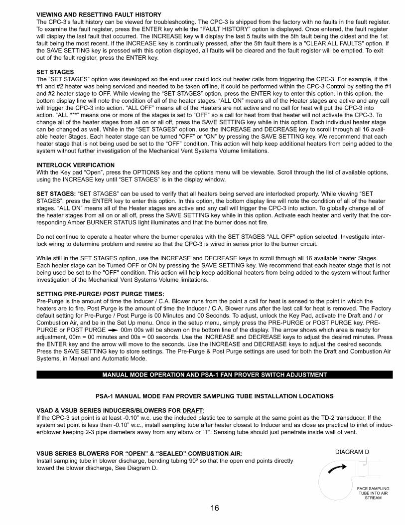
VIEWING AND RESETTING FAULT HISTORYThe CPC-3's fault history can be viewed for troubleshooting. The CPC-3 is shipped from the factory with no faults in the fault register.To examine the fault register, press the ENTER key while the “FAULT HISTORY” option is displayed. Once entered, the fault registerwill display the last fault that occurred. The INCREASE key will display the last 5 faults with the 5th fault being the oldest and the 1stfault being the most recent. If the INCREASE key is continually pressed, after the 5th fault there is a "CLEAR ALL FAULTS" option. Ifthe SAVE SETTING key is pressed with this option displayed, all faults will be cleared and the fault register will be emptied. To exitout of the fault register, press the ENTER key.
SET STAGESThe “SET STAGES” option was developed so the end user could lock out heater calls from triggering the CPC-3. For example, if the#1 and #2 heater was being serviced and needed to be taken offline, it could be performed within the CPC-3 Control by setting the #1and #2 heater stage to OFF. While viewing the “SET STAGES” option, press the ENTER key to enter this option. In this option, thebottom display line will note the condition of all of the heater stages. “ALL ON” means all of the Heater stages are active and any callwill trigger the CPC-3 into action. “ALL OFF” means all of the Heaters are not active and no call for heat will put the CPC-3 intoaction. “ALL ***” means one or more of the stages is set to “OFF” so a call for heat from that heater will not activate the CPC-3. Tochange all of the heater stages from all on or all off, press the SAVE SETTING key while in this option. Each individual heater stagecan be changed as well. While in the “SET STAGES” option, use the INCREASE and DECREASE key to scroll through all 16 avail-able heater Stages. Each heater stage can be turned “OFF” or “ON” by pressing the SAVE SETTING key. We recommend that eachheater stage that is not being used be set to the “OFF” condition. This action will help keep additional heaters from being added to thesystem without further investigation of the Mechanical Vent Systems Volume limitations.
INTERLOCK VERIFICATIONWith the Key pad “Open”, press the OPTIONS key and the options menu will be viewable. Scroll through the list of available options,using the INCREASE key until “SET STAGES” is in the display window.
SET STAGES: “SET STAGES” can be used to verify that all heaters being served are interlocked properly. While viewing “SETSTAGES”, press the ENTER key to enter this option. In this option, the bottom display line will note the condition of all of the heaterstages. “ALL ON” means all of the Heater stages are active and any call will trigger the CPC-3 into action. To globally change all ofthe heater stages from all on or all off, press the SAVE SETTING key while in this option. Activate each heater and verify that the cor-responding Amber BURNER STATUS light illuminates and that the burner does not fire.
Do not continue to operate a heater where the burner operates with the SET STAGES "ALL OFF" option selected. Investigate inter-lock wiring to determine problem and rewire so that the CPC-3 is wired in series prior to the burner circuit.
While still in the SET STAGES option, use the INCREASE and DECREASE keys to scroll through all 16 available heater Stages.Each heater stage can be Turned OFF or ON by pressing the SAVE SETTING key. We recommend that each heater stage that is notbeing used be set to the "OFF" condition. This action will help keep additional heaters from being added to the system without furtherinvestigation of the Mechanical Vent Systems Volume limitations.
SETTING PRE-PURGE/ POST PURGE TIMES:Pre-Purge is the amount of time the Inducer / C.A. Blower runs from the point a call for heat is sensed to the point in which theheaters are to fire. Post Purge is the amount of time the Inducer / C.A. Blower runs after the last call for heat is removed. The Factorydefault setting for Pre-Purge / Post Purge is 00 Minutes and 00 Seconds. To adjust, unlock the Key Pad, activate the Draft and / orCombustion Air, and be in the Set Up menu. Once in the setup menu, simply press the PRE-PURGE or POST PURGE key. PRE-PURGE or POST PURGE 00m 00s will be shown on the bottom line of the display. The arrow shows which area is ready foradjustment, 00m = 00 minutes and 00s = 00 seconds. Use the INCREASE and DECREASE keys to adjust the desired minutes. Pressthe ENTER key and the arrow will move to the seconds. Use the INCREASE and DECREASE keys to adjust the desired seconds.Press the SAVE SETTING key to store settings. The Pre-Purge & Post Purge settings are used for both the Draft and Combustion AirSystems, in Manual and Automatic Mode.
MANUAL MODE OPERATION AND PSA-1 FAN PROVER SWITCH ADJUSTMENT
PSA-1 MANUAL MODE FAN PROVER SAMPLING TUBE INSTALLATION LOCATIONS
VSAD & VSUB SERIES INDUCERS/BLOWERS FOR DRAFT:If the CPC-3 set point is at least -0.10” w.c. use the included plastic tee to sample at the same point as the TD-2 transducer. If thesystem set point is less than -0.10” w.c., install sampling tube after heater closest to Inducer and as close as practical to inlet of induc-er/blower keeping 2-3 pipe diameters away from any elbow or “T”. Sensing tube should just penetrate inside wall of vent.
VSUB SERIES BLOWERS FOR “OPEN” & “SEALED” COMBUSTION AIR:Install sampling tube in blower discharge, bending tubing 90º so that the open end points directlytoward the blower discharge, See Diagram D.
16
FACE SAMPLINGTUBE INTO AIR
STREAM
DIAGRAM D

17
PSA-1 MANUAL MODE FAN PROVER SWITCH ADJUSTMENT
The manual mode allows the Inducer / C.A. Blower to be temporarily operated at a fixed speed. This feature is incorporated into theCPC-3 in the event that the TD-series Transducer becomes inoperable. Without proper transducer operation the CPC-3 controller willgo into a hard lockout after one restart attempt. Important: Fixed speed inducer/blower operation may limit the number of heaters thatcan be operated, since adjusting the speed of the inducer/blower to accommodate all heaters may create excessive draft/combustionair when fewer heaters are operating. If excessive draft/combustion air is present when a single heater is operating the number ofheaters allowed to operate must be reduced until draft/combustion air is acceptable for all operational scenarios.
1. Determine number of heaters necessary for temporary emergency operation. Shut off individual disconnect switches to all heaters not needed.
2. Follow the heating equipment manufacturer's instructions for sampling draft. In their absence drill a draft sampling hole in the vent riser after each draft diverter or between the flue outlet and the draft hood / barometric draft control of each appliance.
3. Turn adjustment screw on the PSA-1 fan prover counter-clockwise until it stops.
4. Unlock the CPC-3 keypad. Press the appropriate (Draft or Combustion Air) SET UP key. Press the AUTO/MANUAL key to change the operation mode from A (Automatic) to M (Manual). This speed is factory set at 40%, but can be adjusted.
4A. Adjusting Manual Speed: With the control in manual mode and the Inducer Setup Menu open, use the "INCREASE" key untilthe MANUAL SPEED OFF is shown on the bottom line of the display. To change the speed, press the "ENTER" key. The OFF text will be replaced by the % Speed that is set within Manual Mode.
5. Activate heaters selected for emergency operation. When the calls for heat are sensed the control will signal the VFD to run the inducer/blower at the 40% factory default setting. Use the INCREASE and DECREASE key until acceptable draft readings are established. The system will not respond to a change until the SAVE SETTING key is pressed.
6. While the heaters and inducer/blower continue to operate, turn the PSA-1 adjustment screw ½ turn clockwise and wait 30 seconds.Repeat this procedure until the CPC-3 locks out the heaters. Adjust the PSA-1 adjustment screw ¼ turn counter clockwise.
7. To reset the CPC-3 press the OPTIONS key. Press the INCREASE key until “FAULT HISTORY” appears in the display. Press ENTER and than press the INCREASE key until “CLEAR ALL FAULTS” appears in the display. Press SAVE SETTIN" key to reset the CPC-3. Press "OPTIONS" to exit.
8. Operate heaters individually and together to verify PSA-1 fan prover setting and individual heater draft/combustion air levels.
MAINTENANCE
Disconnect the power supply when making wiring connections or when working around the fan impeller and motor. Failure to do socan result in electrical shock, personal injury, death or property damage.
The Tjernlund Auto-Draft® Inducer / C.A. Blower is designed for continuous use. The motor is equipped with permanently lubricatedsealed ball bearings, which do not require oiling.
A vent pipe inspection must be performed annually. The inspection should include checking all vent pipe and connections for block-age and leaks. A safety interlock test must also be performed.
For Induced Draft gas applications no regular maintenance is required. For Induced Draft oil applications inspect impeller after (3)months and set up a periodic inspection and cleaning routine as necessary.
For VSUB-Series Combustion Air Blowers inspect installer supplied prefilters, intake hood screen and blower wheel every 3-6 monthsto remove foreign material such as leaves, lint or other debris.
HOW TO OBTAIN SERVICE ASSISTANCE
1. If you have any questions about your Auto-Draft® Inducer / C.A. Blower or if it requires adjustment, repair or routine maintenance, we suggest that you initially contact your installer, contractor or service agency.
2. If you require technical information contact Tjernlund Products, Inc. at 1-800-255-4208 or visit www.tjernlund.com.
When contacting Tjernlund Products, Inc., please have the following information available:1. Model and Lot # of the Auto-Draft® Inducer / C.A. Blower 2. Name and address of installer and service agency3. Date of original installation and dates any service work was performed4. Details of the problem


![Cpc Rl Gauge User Manual Ajc[2]](https://img.pdfslide.us/doc/110x75/577ce4c81a28abf1038f25fc/cpc-rl-gauge-user-manual-ajc2.jpg)