Embed Size (px)
Citation preview
OL-31220-01
C H A P T E R 12
Events & AlarmsThis chapter describes how to view events and alarms in Cisco PAM. It also includes instructions to configure the event policies that define how events are captured and managed.
Events can be viewed in the following ways:
• As a list using the Events or Alarms modules.
• Using an audit trail of events initiated by a user.
• By personnel photos.
• Using graphic maps to display where events occur on a floor or building. You can also use the map to trigger actions for a device or door.
Tip To create actions that are triggered by an event, see Chapter 13, “Configuring Automated Tasks”. To view live and recorded video for events and alarms, see Chapter 15, “Video Monitoring”.
Contents• Viewing Events, Alarms and Audit Trail Records, page 12-3
– Events and Alarms in Cisco PAM 1.5.0, page 12-3
– Viewing Events, page 12-4
– Viewing Alarms, page 12-8
– Viewing Audit Trail Records, page 12-13
– Viewing Recent Events for a Device, Driver, or Location, page 12-15
• Viewing Events Using Personnel Photos, page 12-17
– Viewing Event Photos, page 12-17
– Adding a Color Border to Event Photos (Credential Watch), page 12-18
– Using Filters to Limit the Photos and Doors Events Displayed by Event Photos, page 12-21
• Recording External Events, page 12-25
• Viewing Workstation Activity, page 12-28
• Configuring Events and Alarms, page 12-29
– Modifying Default Event Policies, page 12-29
12-1CPAM 1.5 User Guide
Chapter 12 Events & AlarmsContents
– Event Policy Manager in Cisco PAM 1.5.0, page 12-30
– Automatically Open the Alarm Window, page 12-34
– Configuring Time Schedules, page 12-34
– Configuring Alert Sounds, page 12-37
– Setting Event and Alarm Priorities, page 12-38
– Defining User Privileges for Editing Events, page 12-38
• Using Graphic Maps, page 12-40
– Graphic Maps in Cisco PAM 1.5.0, page 12-40
– Graphic Map Viewer, page 12-41
– Graphic Map Editor, page 12-44
• Backing Up and Archiving Events, page 12-51
– Including Events In System Backups, page 12-51
– Pruning and Archiving Old Events, page 12-51
– Creating Reports from Pruned Events, page 12-52
12-2CPAM 1.5 User Guide
OL-31220-01
Chapter 12 Events & AlarmsViewing Events, Alarms and Audit Trail Records
Viewing Events, Alarms and Audit Trail Records Events and alarms are captured in real time, and are accessed in the Events & Alarms menu, under the Monitoring sub-menu. Alarms are critical or important events. Audit trails are events initiated by users.
This section includes the following:
• Understanding Live and Archived Events, page 12-3
• Understanding Event Timestamps, page 12-4
• Viewing Events, page 12-4
• Viewing Alarms, page 12-8
– Alarm States, page 12-9
– Alarm Detail Window, page 12-9
• Viewing Audit Trail Records, page 12-13
Tip See Configuring Events and Alarms, page 12-29 to define or modify event types. To copy or move events to a historical events archive, see Backing Up and Archiving Events, page 12-51.
Events and Alarms in Cisco PAM 1.5.0If the profile enhancement feature is set in the system configuration settings(Data Entry/Validation - Login, page 17-10), the following changes are impacted in this module:
• The events and alarms are displayed to users based on hierarchical location assigned to their user profiles. For example: if a location-restricted user “campusadmin”is assigned to a location “San Jose Campus”, the user can view events and alarms related to this location and its sub locations only.
• The location-restricted user cannot view events of the following drivers and modules:
– Driver level commands
– Cleared Alarms event
– Device commands
– Workstation
– Audit Trail
Note These points are applicable only when the Profile enhancement feature is set in the System Configuration of the Cisco PAM. Otherwise the Cisco PAM appliance retains its behavior as in the previous version(1.3.2).
Understanding Live and Archived Events• You can include or exclude events from system backups. Excluding events reduces the size of the
backup file.
12-3CPAM 1.5 User Guide
OL-31220-01
Chapter 12 Events & AlarmsViewing Events, Alarms and Audit Trail Records
• The Event Monitoring window includes all live events in the system. Live events can be pruned to remove them from the main database to improve system performance. Pruned events are not displayed in the Event Monitoring window. Old events can also be archived and backed up to a remote server.
See the “Backing Up and Archiving Events” section on page 12-51 for more information.
Understanding Event TimestampsBeginning with Release 1.3.0, events display the timestamp of the Cisco PAM PC workstation used to view the events. In previous releases, events displayed the Cisco PAM appliance timestamp.
Viewing EventsYou can view events in a list, or double-click an event to view detailed information. You can also right-click an event to select commands, change the event properties, or view associated video.
Step 1 Select Events from the Events & Alarms menu, under the Monitoring sub-menu. The Events window (Figure 12-1) shows the most recent events in the access-control system.
Figure 12-1 Events Module Main Window
Tip Beginning with Release 1.3.0, events display the timestamp of the Cisco PAM PC workstation used to view the events. In previous releases, events displayed the Cisco PAM appliance timestamp.
Step 2 Modify the list of records using the following toolbar controls:
• Scroll Lock: Disables or enables automatic scrolling of the list as new events are inserted.
• Clear List: Clears all events from the table. Only new events are displayed.
12-4CPAM 1.5 User Guide
OL-31220-01
Chapter 12 Events & AlarmsViewing Events, Alarms and Audit Trail Records
• View...: Select an event and click View to display the detail window (Figure 12-2). You can also double-click the event.
• Report...: View the selected events in a separate window, or save the information in a file. See Creating Reports, page 4-10.
• Columns...: Define the columns displayed and their order. See Revising the Column Display, page 4-14.
• Filter: Filter the events to display a sub-set of records. To change the number of viewable events, select Max rows. See Using Filters, page 4-12.
• Search: See Search, page 4-16.
Step 3 Select a record and click View... to open the detail window (Figure 12-2). You can also double-click the record.
Figure 12-2 Events Module Detail Window
Step 4 Review the properties and actions for the record. See Table 12-1 for field descriptions.
Note Event fields available vary depending on the type of event. The following example is for a door event.
12-5CPAM 1.5 User Guide
OL-31220-01
Chapter 12 Events & AlarmsViewing Events, Alarms and Audit Trail Records
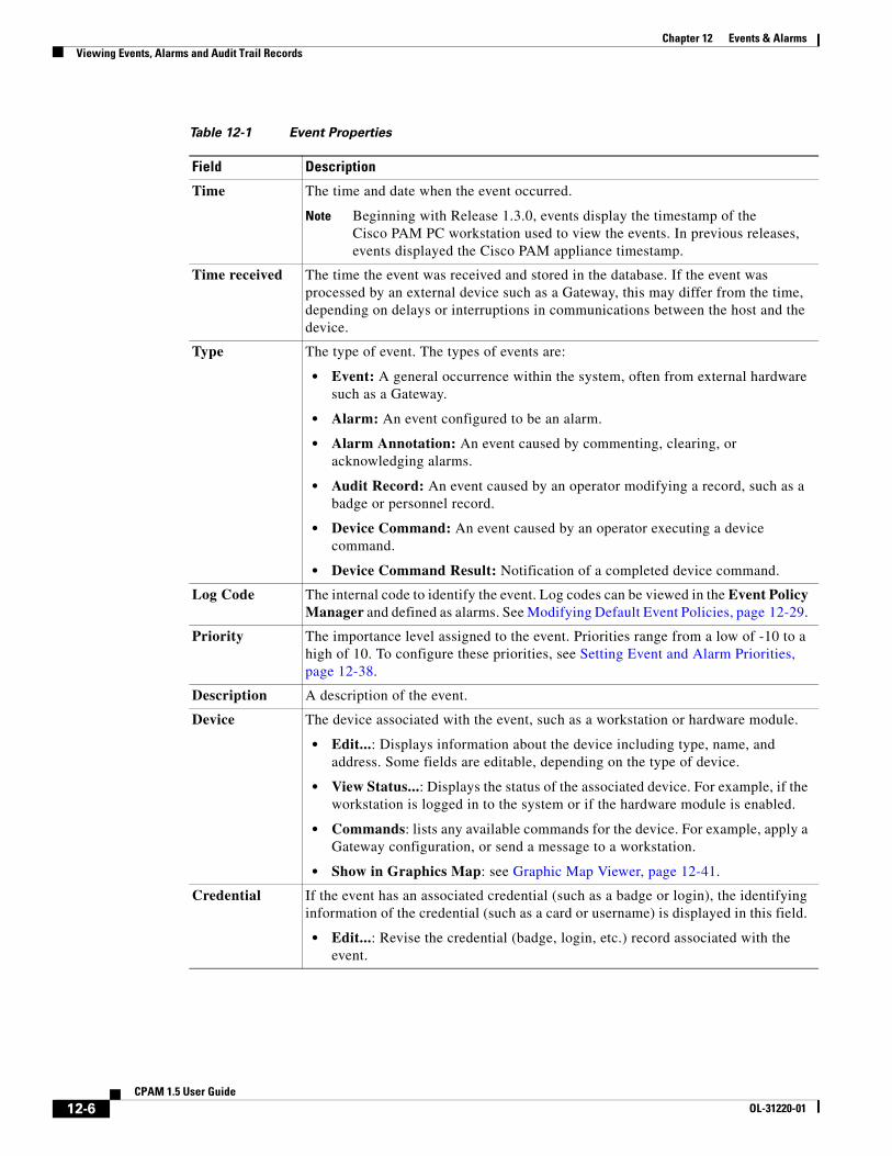
Table 12-1 Event Properties
Field Description
Time The time and date when the event occurred.
Note Beginning with Release 1.3.0, events display the timestamp of the Cisco PAM PC workstation used to view the events. In previous releases, events displayed the Cisco PAM appliance timestamp.
Time received The time the event was received and stored in the database. If the event was processed by an external device such as a Gateway, this may differ from the time, depending on delays or interruptions in communications between the host and the device.
Type The type of event. The types of events are:
• Event: A general occurrence within the system, often from external hardware such as a Gateway.
• Alarm: An event configured to be an alarm.
• Alarm Annotation: An event caused by commenting, clearing, or acknowledging alarms.
• Audit Record: An event caused by an operator modifying a record, such as a badge or personnel record.
• Device Command: An event caused by an operator executing a device command.
• Device Command Result: Notification of a completed device command.
Log Code The internal code to identify the event. Log codes can be viewed in the Event Policy Manager and defined as alarms. See Modifying Default Event Policies, page 12-29.
Priority The importance level assigned to the event. Priorities range from a low of -10 to a high of 10. To configure these priorities, see Setting Event and Alarm Priorities, page 12-38.
Description A description of the event.
Device The device associated with the event, such as a workstation or hardware module.
• Edit...: Displays information about the device including type, name, and address. Some fields are editable, depending on the type of device.
• View Status...: Displays the status of the associated device. For example, if the workstation is logged in to the system or if the hardware module is enabled.
• Commands: lists any available commands for the device. For example, apply a Gateway configuration, or send a message to a workstation.
• Show in Graphics Map: see Graphic Map Viewer, page 12-41.
Credential If the event has an associated credential (such as a badge or login), the identifying information of the credential (such as a card or username) is displayed in this field.
• Edit...: Revise the credential (badge, login, etc.) record associated with the event.
12-6CPAM 1.5 User Guide
OL-31220-01
Chapter 12 Events & AlarmsViewing Events, Alarms and Audit Trail Records
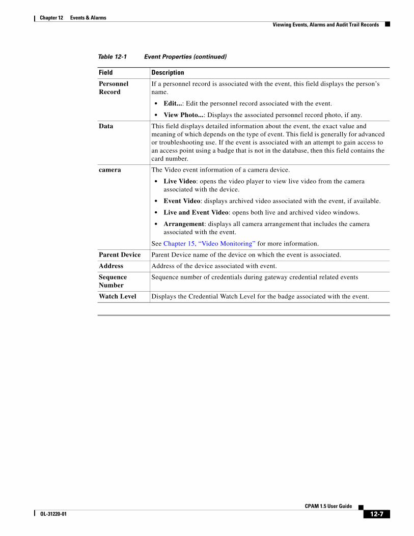
Personnel Record
If a personnel record is associated with the event, this field displays the person’s name.
• Edit...: Edit the personnel record associated with the event.
• View Photo...: Displays the associated personnel record photo, if any.
Data This field displays detailed information about the event, the exact value and meaning of which depends on the type of event. This field is generally for advanced or troubleshooting use. If the event is associated with an attempt to gain access to an access point using a badge that is not in the database, then this field contains the card number.
camera The Video event information of a camera device.
• Live Video: opens the video player to view live video from the camera associated with the device.
• Event Video: displays archived video associated with the event, if available.
• Live and Event Video: opens both live and archived video windows.
• Arrangement: displays all camera arrangement that includes the camera associated with the event.
See Chapter 15, “Video Monitoring” for more information.
Parent Device Parent Device name of the device on which the event is associated.
Address Address of the device associated with event.
Sequence Number
Sequence number of credentials during gateway credential related events
Watch Level Displays the Credential Watch Level for the badge associated with the event.
Table 12-1 Event Properties (continued)
Field Description
12-7CPAM 1.5 User Guide
OL-31220-01
Chapter 12 Events & AlarmsViewing Events, Alarms and Audit Trail Records
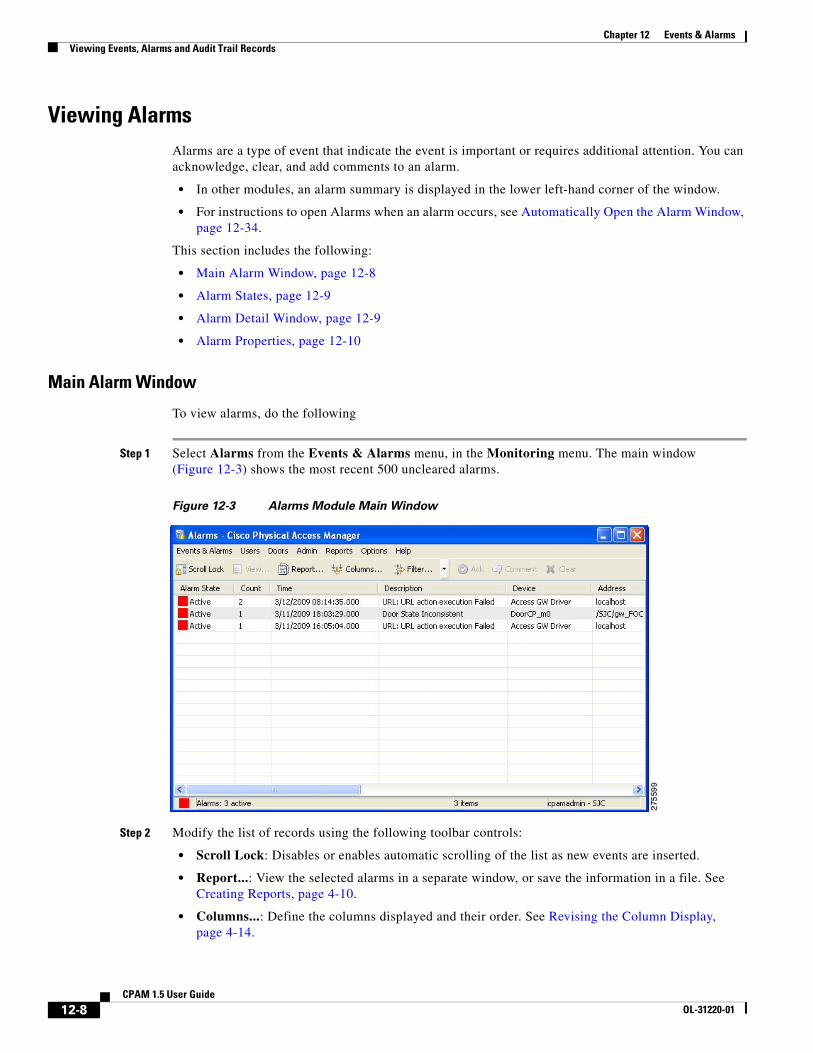
Viewing Alarms Alarms are a type of event that indicate the event is important or requires additional attention. You can acknowledge, clear, and add comments to an alarm.
• In other modules, an alarm summary is displayed in the lower left-hand corner of the window.
• For instructions to open Alarms when an alarm occurs, see Automatically Open the Alarm Window, page 12-34.
This section includes the following:
• Main Alarm Window, page 12-8
• Alarm States, page 12-9
• Alarm Detail Window, page 12-9
• Alarm Properties, page 12-10
Main Alarm Window
To view alarms, do the following
Step 1 Select Alarms from the Events & Alarms menu, in the Monitoring menu. The main window (Figure 12-3) shows the most recent 500 uncleared alarms.
Figure 12-3 Alarms Module Main Window
Step 2 Modify the list of records using the following toolbar controls:
• Scroll Lock: Disables or enables automatic scrolling of the list as new events are inserted.
• Report...: View the selected alarms in a separate window, or save the information in a file. See Creating Reports, page 4-10.
• Columns...: Define the columns displayed and their order. See Revising the Column Display, page 4-14.
12-8CPAM 1.5 User Guide
OL-31220-01
Chapter 12 Events & AlarmsViewing Events, Alarms and Audit Trail Records
• Filter: Filter the alarms to display a sub-set of records. To change the number of displayed alarms, select Max rows. See Using Filters, page 4-12.
Step 3 Change the state of an alarm, add a comment, or acknowledge the alarm.
Use the following toolbar buttons or right-click the entry and select an option from the menu.
• Ack: Acknowledges an alarm, placing it in an acknowledged state. This means that the operator is aware of the alarm, but it has not been resolved. A solid orange color indicates this state.
• Comment: Adds a comment to an alarm. Does not change the state of the alarm. A new comment may be entered, or a previously entered comment may be selected from the drop-down list.
• Clear: Places the alarm in a cleared state (resolved) and changes the icon to green.
See Alarm States for more information. The alarms state options are also available in the detail window.
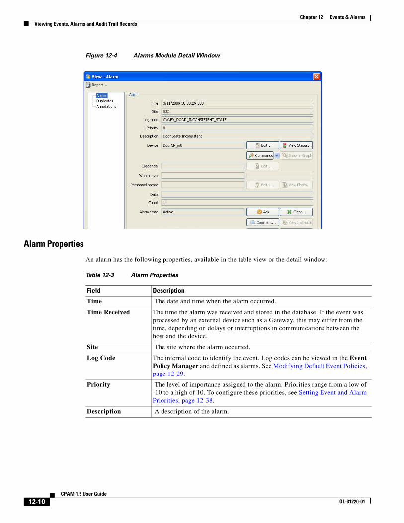
Step 4 Select an alarm and click View... to open the detail window (Figure 12-4 on page 12-10). You can also double-click the record. See Alarm Properties, page 12-10 for field descriptions.
Alarm States
An alarm may be in one of several states, and these states have an associated solid or blinking color.
Alarm Detail Window
The detail window (Figure 12-4) displays alarm properties and provides a number of actions:
• The Alarms tab displays the properties of the alarm and provides a number of actions. See Alarm Properties, page 12-10 for more information.
• The Duplicates tab displays duplicate alarms. All attributes are the same except the time.
• The Annotations tab displays any annotations made to the selected alarm. Valid alarm annotations include:
– Acknowledge Alarm
– Clear Alarm
– Comment Alarm
Table 12-2 Alarm States
State Color Description
Active Blinking red The alarm is new, unacknowledged, and unresolved.
Acknowledged Solid orange An operator is aware of the alarm, though it remains unresolved.
Cleared Solid green The alarm has been acknowledged and resolved. Note that the default filter in the Alarms module hides cleared alarms, so these are generally not seen.
12-9CPAM 1.5 User Guide
OL-31220-01
Chapter 12 Events & AlarmsViewing Events, Alarms and Audit Trail Records
Figure 12-4 Alarms Module Detail Window
Alarm Properties
An alarm has the following properties, available in the table view or the detail window:
Table 12-3 Alarm Properties
Field Description
Time The date and time when the alarm occurred.
Time Received The time the alarm was received and stored in the database. If the event was processed by an external device such as a Gateway, this may differ from the time, depending on delays or interruptions in communications between the host and the device.
Site The site where the alarm occurred.
Log Code The internal code to identify the event. Log codes can be viewed in the Event Policy Manager and defined as alarms. See Modifying Default Event Policies, page 12-29.
Priority The level of importance assigned to the alarm. Priorities range from a low of -10 to a high of 10. To configure these priorities, see Setting Event and Alarm Priorities, page 12-38.
Description A description of the alarm.
12-10CPAM 1.5 User Guide
OL-31220-01
Chapter 12 Events & AlarmsViewing Events, Alarms and Audit Trail Records
Device The device associated with the alarm, such as a workstation or hardware module.
• Edit...: Displays information about the device including type, name, and address. Some fields are editable, depending on the type of device.
• View Status...: Displays the status of the associated device. For example, if the workstation is logged in to the system or if the hardware module is enabled.
• Commands: lists any available commands for the device. For example, apply a Gateway configuration, or send a message to a workstation.
• Show in Graphics : see Graphic Map Viewer, page 12-41.
Credential If the alarm has an associated credential (such as a badge or login), the identifying information of the credential (such as a card or username) is displayed in this field.
• Edit...: Revise the credential (badge, login, etc.) record associated with the event.
Watch Level Displays the Credential Watch Level for the badge associated with the event. See Adding a Color Border to Event Photos (Credential Watch), page 12-18.
• Edit...: Revise the credential watch level associated with the badge.
Address The address of the device.
Personnel Record If a personnel record is associated with the alarm, this field displays the person’s name.
• Edit...: Edit the personnel record associated with the event.
• View Photo...: Displays the associated personnel record photo, if any.
Data This field displays detailed information about the event, the exact value and meaning of which depends on the type of event. This field is generally for advanced or troubleshooting use. If the event is associated with an attempt to gain access to an access point using a badge that is not in the database, this field contains the card number.
Count The number of times this alarm has occurred, including duplicates. Duplicate alarms have all attributes the same except time).
Alarm State The state of the alarm. See Alarm States, page 12-9.
• Ack...: Acknowledges the alarm, placing it in an acknowledged state. This means that the operator is aware of the alarm, but it has not been resolved. A solid orange color indicates this state.
• Clear...: Clears the alarm, placing it in a cleared state. This means that the alarm has been resolved. A solid green color indicates this state.
• Comment...: Adds a comment to an alarm. Does not change the state of the alarm. A new comment may be entered, or a previously entered comment may be selected from the drop-down list.
• View Instructions...: Opens a detail window with instructions for dealing with the type of alarm, if any.
Table 12-3 Alarm Properties (continued)
Field Description
12-11CPAM 1.5 User Guide
OL-31220-01
Chapter 12 Events & AlarmsViewing Events, Alarms and Audit Trail Records
Target device The device associated with the event. For example, the device where a command was executed.
• Edit: modify the device settings.
camera The camera associated with the device.
• Live Video: opens the video player to view live video from the camera associated with the device.
• Event Video: displays archived video associated with the event, if available.
See Chapter 15, “Video Monitoring” for more information.
Table 12-3 Alarm Properties (continued)
Field Description
12-12CPAM 1.5 User Guide
OL-31220-01
Chapter 12 Events & AlarmsViewing Events, Alarms and Audit Trail Records
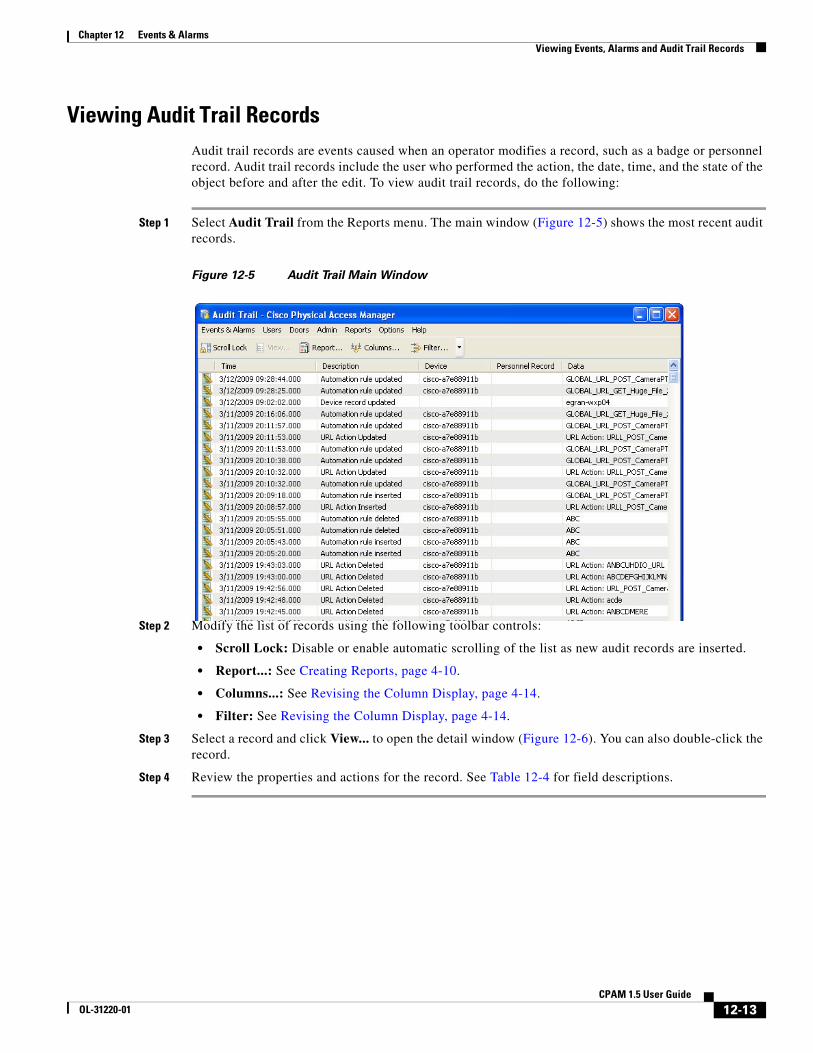
Viewing Audit Trail Records Audit trail records are events caused when an operator modifies a record, such as a badge or personnel record. Audit trail records include the user who performed the action, the date, time, and the state of the object before and after the edit. To view audit trail records, do the following:
Step 1 Select Audit Trail from the Reports menu. The main window (Figure 12-5) shows the most recent audit records.
Figure 12-5 Audit Trail Main Window
Step 2 Modify the list of records using the following toolbar controls:
• Scroll Lock: Disable or enable automatic scrolling of the list as new audit records are inserted.
• Report...: See Creating Reports, page 4-10.
• Columns...: See Revising the Column Display, page 4-14.
• Filter: See Revising the Column Display, page 4-14.
Step 3 Select a record and click View... to open the detail window (Figure 12-6). You can also double-click the record.
Step 4 Review the properties and actions for the record. See Table 12-4 for field descriptions.
12-13CPAM 1.5 User Guide
OL-31220-01
Chapter 12 Events & AlarmsViewing Events, Alarms and Audit Trail Records
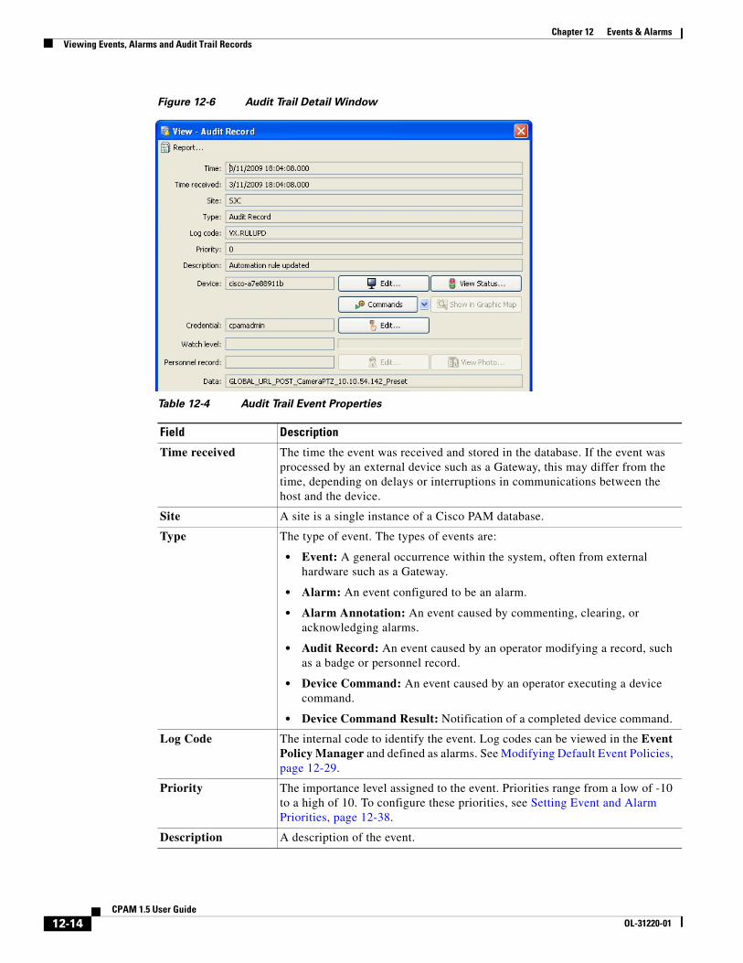
Figure 12-6 Audit Trail Detail Window
Table 12-4 Audit Trail Event Properties
Field Description
Time received The time the event was received and stored in the database. If the event was processed by an external device such as a Gateway, this may differ from the time, depending on delays or interruptions in communications between the host and the device.
Site A site is a single instance of a Cisco PAM database.
Type The type of event. The types of events are:
• Event: A general occurrence within the system, often from external hardware such as a Gateway.
• Alarm: An event configured to be an alarm.
• Alarm Annotation: An event caused by commenting, clearing, or acknowledging alarms.
• Audit Record: An event caused by an operator modifying a record, such as a badge or personnel record.
• Device Command: An event caused by an operator executing a device command.
• Device Command Result: Notification of a completed device command.
Log Code The internal code to identify the event. Log codes can be viewed in the Event Policy Manager and defined as alarms. See Modifying Default Event Policies, page 12-29.
Priority The importance level assigned to the event. Priorities range from a low of -10 to a high of 10. To configure these priorities, see Setting Event and Alarm Priorities, page 12-38.
Description A description of the event.
12-14CPAM 1.5 User Guide
OL-31220-01
Chapter 12 Events & AlarmsViewing Events, Alarms and Audit Trail Records
Viewing Recent Events for a Device, Driver, or LocationTo view a list of recent events for a device or driver, do the following:
Step 1 Select Hardware or Locations & Doors from the Doors menu.
Step 2 (Optional) Use the menu bar tools to filter or search the entries. See Toolbar Features, page 4-10.
Device The device associated with the event, such as a workstation or hardware module.
• Edit...: Displays information about the device including type, name, and address. Some fields are editable, depending on the type of device.
• View Status...: Displays the status of the associated device. For example, if the workstation is logged in to the system or if the hardware module is enabled.
• Commands: lists any available commands for the device. For example, apply a Gateway configuration, or send a message to a workstation.
• Show in Graphics Map: see Graphic Map Viewer, page 12-41.
Credential If the event has an associated credential (such as a badge or login), the identifying information of the credential (such as a card or username) is displayed in this field.
• Edit...: Revise the credential (badge, login, etc.) record associated with the event.
Watch Level Displays the Credential Watch Level for the badge associated with the event. See Adding a Color Border to Event Photos (Credential Watch), page 12-18.
• Edit...: Revise the credential watch level associated with the badge.
Personnel Record If a personnel record is associated with the event, this field displays the person’s name.
• Edit...: Edit the personnel record associated with the event.
• View Photo...: Displays the associated personnel record photo, if any.
Data This field displays detailed information about the event, the exact value and meaning of which depends on the type of event. This field is generally for advanced or troubleshooting use. If the event is associated with an attempt to gain access to an access point using a badge that is not in the database, then this field contains the card number.
Modified Record The item changed by the user.
• View Current...: Opens a detail window of the modified record, as it exists currently.
• View Before...: Opens a detail window of the modified record, as it existed before the modification.
• View After...: Opens a detail window of the modified record, as it existed after the modification.
Table 12-4 Audit Trail Event Properties (continued)
Field Description
12-15CPAM 1.5 User Guide
OL-31220-01
Chapter 12 Events & AlarmsViewing Events, Alarms and Audit Trail Records
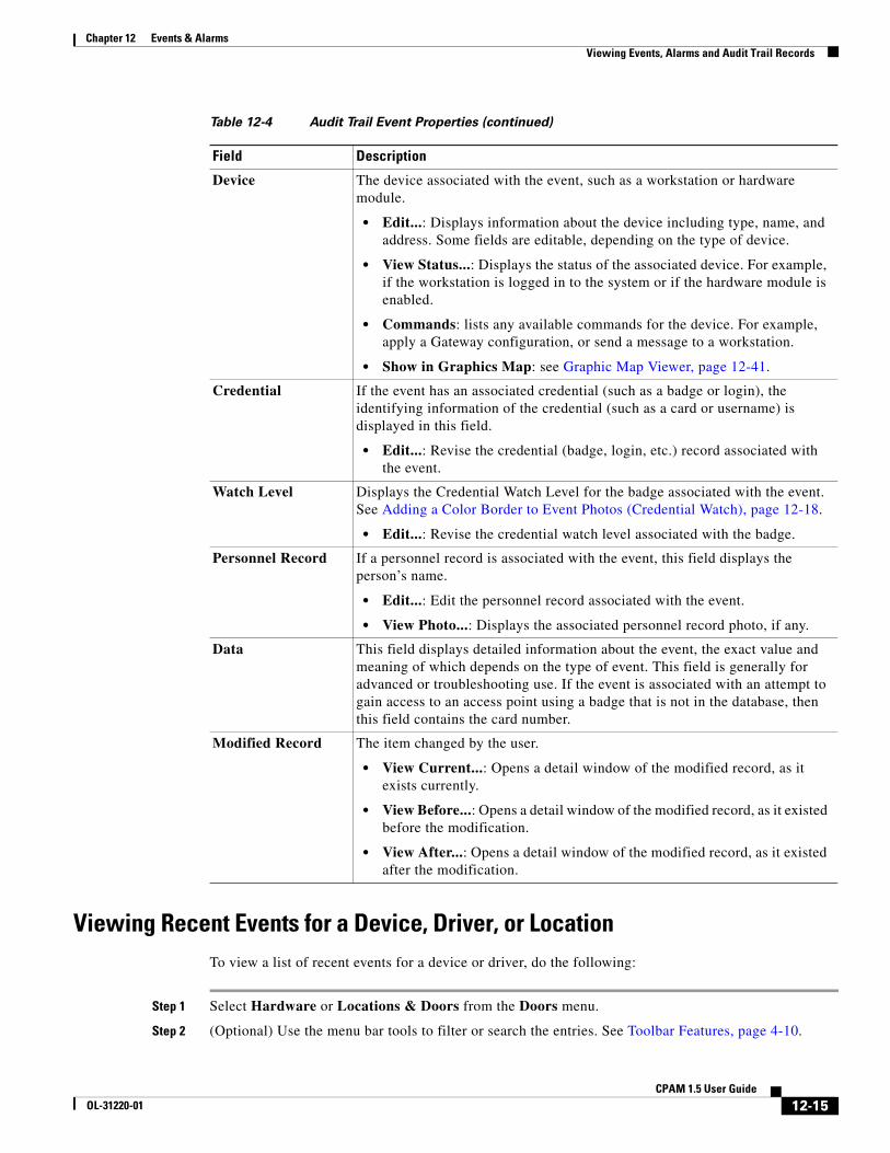
Step 3 Right-click the device or driver, and select View Recent Events from the drop-down menu, as shown in Figure 12-7.
Figure 12-7 View Recent Events Menu
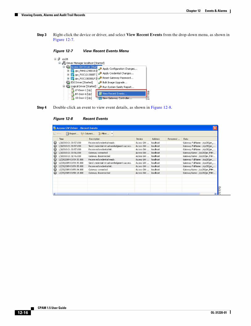
Step 4 Double-click an event to view event details, as shown in Figure 12-8.
Figure 12-8 Recent Events
12-16CPAM 1.5 User Guide
OL-31220-01
Chapter 12 Events & AlarmsViewing Events Using Personnel Photos
Viewing Events Using Personnel Photos Use the Event Photos module to display events using personnel photos.
This section includes the following:
• Viewing Event Photos, page 12-17
• Adding a Color Border to Event Photos (Credential Watch), page 12-18
• Using Filters to Limit the Photos and Doors Events Displayed by Event Photos, page 12-21
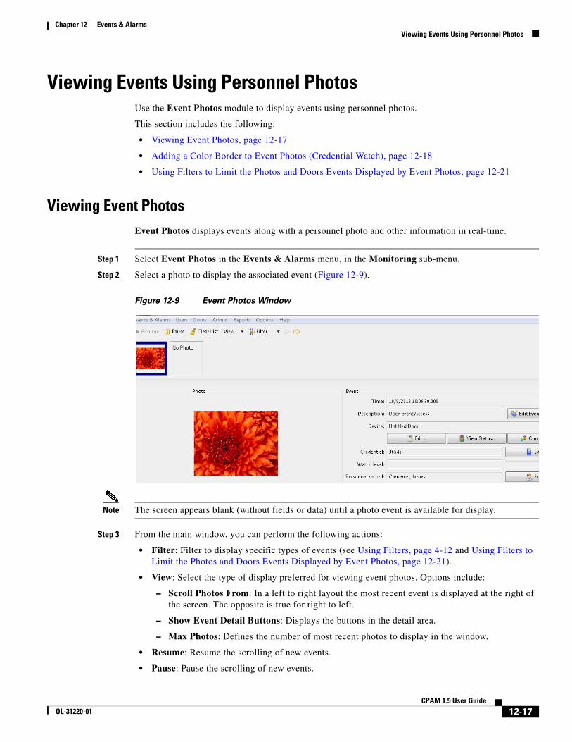
Viewing Event PhotosEvent Photos displays events along with a personnel photo and other information in real-time.
Step 1 Select Event Photos in the Events & Alarms menu, in the Monitoring sub-menu.
Step 2 Select a photo to display the associated event (Figure 12-9).
Figure 12-9 Event Photos Window
Note The screen appears blank (without fields or data) until a photo event is available for display.
Step 3 From the main window, you can perform the following actions:
• Filter: Filter to display specific types of events (see Using Filters, page 4-12 and Using Filters to Limit the Photos and Doors Events Displayed by Event Photos, page 12-21).
• View: Select the type of display preferred for viewing event photos. Options include:
– Scroll Photos From: In a left to right layout the most recent event is displayed at the right of the screen. The opposite is true for right to left.
– Show Event Detail Buttons: Displays the buttons in the detail area.
– Max Photos: Defines the number of most recent photos to display in the window.
• Resume: Resume the scrolling of new events.
• Pause: Pause the scrolling of new events.
12-17CPAM 1.5 User Guide
OL-31220-01
Chapter 12 Events & AlarmsViewing Events Using Personnel Photos
Tip See Viewing Events, Alarms and Audit Trail Records, page 12-3 for field descriptions. To make the event fields read-only, see Configuring Events and Alarms, page 12-29.
Adding a Color Border to Event Photos (Credential Watch) Credential watch allows you to display event photos with a colored border to provide additional information regarding the status of the badge holder.
For example, if a guard uses Event Photos to view photos of the people accessing a door, a colored border can visually signify if the user is a contractor, visitor, etc.
The default credential watch levels are:
• Low: a yellow border around the photo.
• Medium: an orange border around the photo.
• High: a red border around the photo.
You can modify these definitions, or create custom watch levels. For example, if the badge holder has been employed less than one year, an ORANGE border may appear around the photo. If the badge holder is a contractor, a RED border may appear around the photo.
To configure Credential Watch, do the following:
To do this
Step 1 Enable Credential Watch Levels menu:
a. Choose System Configuration from the Admin menu.
b. Choose the Miscellaneous tab.
c. Select the Enable credential watch levels check box.
d. Click Save.
e. Log out and log back in to the Cisco PAM application to activate the changes (select Logout from the Options menu)..
12-18CPAM 1.5 User Guide
OL-31220-01
Chapter 12 Events & AlarmsViewing Events Using Personnel Photos
Step 2 Add credential watch access privileges for user profiles:
a. Select Profiles from the Users menu.
b. Click Add or select an existing profile and click Edit.
c. Click the Module tab.
d. Click Quick Launch.
e. Select the options in the panel to the right.
f. Click Save and Close.
Tip For more information, see Chapter 5, “Configuring User Access for the Cisco PAM Desktop Client”.
(Optional) Assign the profile to the user login, if necessary:
a. Select Login from the Users menu.
b. Click Add or select an existing user and click Edit.
c. Select Profiles.
d. Select the profile that includes the required access privileges.
e. Click Save and Close.
To do this
12-19CPAM 1.5 User Guide
OL-31220-01
Chapter 12 Events & AlarmsViewing Events Using Personnel Photos
Step 3 (Optional) Create or edit the credential watch definitions.
Tip This defines the photo border color and description:
a. Select Credential Watch Levels from the Admin module.
b. Click Add or select an existing level and click Edit.
c. Enter the Name of the level. For example: New Employee.
d. Enter the order number of the level to define the hierarchy of the levels. For example, enter 0 to display the new level at the top of the list. This can also define the relative importance or severity of the levels.
e. Click Choose to select a border color for the photos when using Event Photos.
f. Click Save and Close.
Step 4 Add the credential watch level to a badge configuration:
a. Select Badges from the Admin module.
b. Click Add or select an existing badge and click Edit.
c. Select the General tab.
d. Select the Watch Level from the drop-down menu. For example, New Employee.
To do this
12-20CPAM 1.5 User Guide
OL-31220-01
Chapter 12 Events & AlarmsViewing Events Using Personnel Photos
Using Filters to Limit the Photos and Doors Events Displayed by Event PhotosBy default, Event Photos displays the photos and events for any badge presented to any door on the system. Use the Filter to display only events for a specific door or set of doors. For example, the guard at the front entrance should only see the event photos for badges presented at that particular door.
In addition, the photo associated with a badge is shown two times by default: one time when the credential is read, and one time for the Grant Access event. Use Filters to only display the photo once.
Complete the following instructions to limit the doors and photos displayed by Event Photos:
Step 1 To select specific doors to display event information:
a. Select Edit Filter from the Filters toolbar menu.
b. In the filter window, select the Device tab, and then select the Choose button(Figure 12-10).
c. Select the doors or devices that will display events in Event Photos.
d. Click OK to close the Choose Devices window.
e. Click OK to close the Filter window and save the changes.
Step 5 Open the Event Photos module: select Event Photos from the Events & Alarms menu, in the Monitoring sub-menu.
Step 6 Present the badge to the door card reader to display the associated badge photo in Event Photos. In this example, a dark blue border is displayed and the watch level is “New Employee”.
Note The screen appears blank (without fields or data) until a photo event is available for display.
To do this
12-21CPAM 1.5 User Guide
OL-31220-01

Chapter 12 Events & AlarmsViewing Events Using Personnel Photos
Figure 12-10 Filter Device Window
Step 2 To display the photo once for each badge presentation:
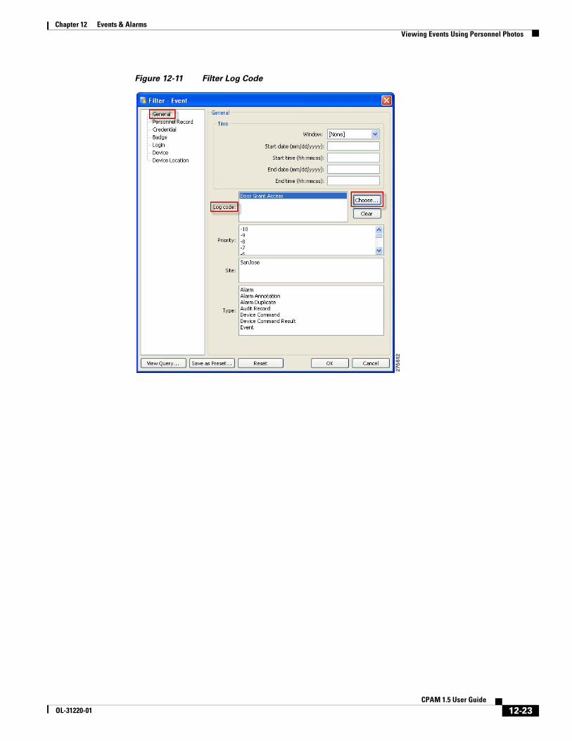
a. In the filter window, select the General tab, and then select the Choose button in the Log Code field (Figure 12-11).
12-22CPAM 1.5 User Guide
OL-31220-01
Chapter 12 Events & AlarmsViewing Events Using Personnel Photos
Figure 12-11 Filter Log Code
12-23CPAM 1.5 User Guide
OL-31220-01
Chapter 12 Events & AlarmsViewing Events Using Personnel Photos
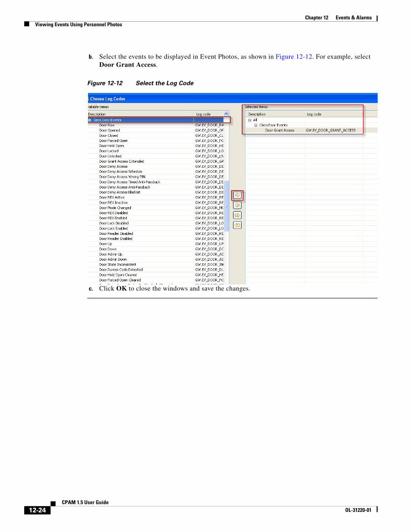
b. Select the events to be displayed in Event Photos, as shown in Figure 12-12. For example, select Door Grant Access.
Figure 12-12 Select the Log Code
c. Click OK to close the windows and save the changes.
12-24CPAM 1.5 User Guide
OL-31220-01
Chapter 12 Events & AlarmsRecording External Events
Recording External EventsExternal applications can record events in Cisco PAM using the recordExtEvent API. Once recorded, the events are displayed in the Events & Alarms Monitoring modules.
External Event Types are defined using the Event Definition Format and imported using the steps described in the following sections.
To record events from external applications, do the following:
1. Define External Event Types Using the Event Definition Format, page 12-25. This file also defines the categories for the log codes.
2. Create a Text File to Define the Event Names in Cisco PAM, page 12-26.
3. Import the Files into Cisco PAM, page 12-26.
4. Add external events and alarms to Cisco PAM using the recordExtEvent API, as described in the Cisco Physical Access Control API Reference Guide.
Define External Event Types Using the Event Definition FormatUse the Event Definition Format to create an XML file that defines the event and alarm codes used to add external events to Cisco PAM. This file also defines the category for the events and is imported into Cisco PAM to create the codes.
Example
In the following XML example:
• The concatenation rule is: AE.<logcode_prefix>_<logcode>
• Event category: AE.Cisco_VSM
• The log codes for the category are: AE.VS_VSM_Sample1 and AE.VS_VSM_Sample2
<appext_eventdefns xmlns:xsi="http://www.w3.org/2001/XMLSchema-instance"> <appext_entry appname="Cisco_VSM" logcode_prefix="VS"> <ext_event_defn logcode="VSM_Sample1" priority="10" description="VSM Sample Event-1"/> <ext_event_defn logcode="VSM_Sample2" priority="10" description="VSM Sample Event-2" isAlarm="true"/> </appext_entry></appext_eventdefns>
The file is saved with the .xml extension. For example: SampleExtEventDefns.xml.
12-25CPAM 1.5 User Guide
OL-31220-01
Chapter 12 Events & AlarmsRecording External Events
Create a Text File to Define the Event Names in Cisco PAMTo define the log code names displayed in Cisco PAM, create a text file that defines a string name for each event and the event category.
In the following example, the string name for the two events and the event category are defined:
VS_VSM_Sample1=Sample Event-1
VS_VSM_Sample2=Sample Event-2
Cisco_VSM=Cisco Video Surveillance Manager
The file is saved with the .properties extension. For example: AppExtMessages.properties.
Import the Files into Cisco PAMOnce the XML and properties files are created, import the files into the Cisco PAM External Events module.
To do this
Step 1 Select External Events from the Events & Alarms menu.
Step 2 Click Import.
12-26CPAM 1.5 User Guide
OL-31220-01
Chapter 12 Events & AlarmsRecording External Events
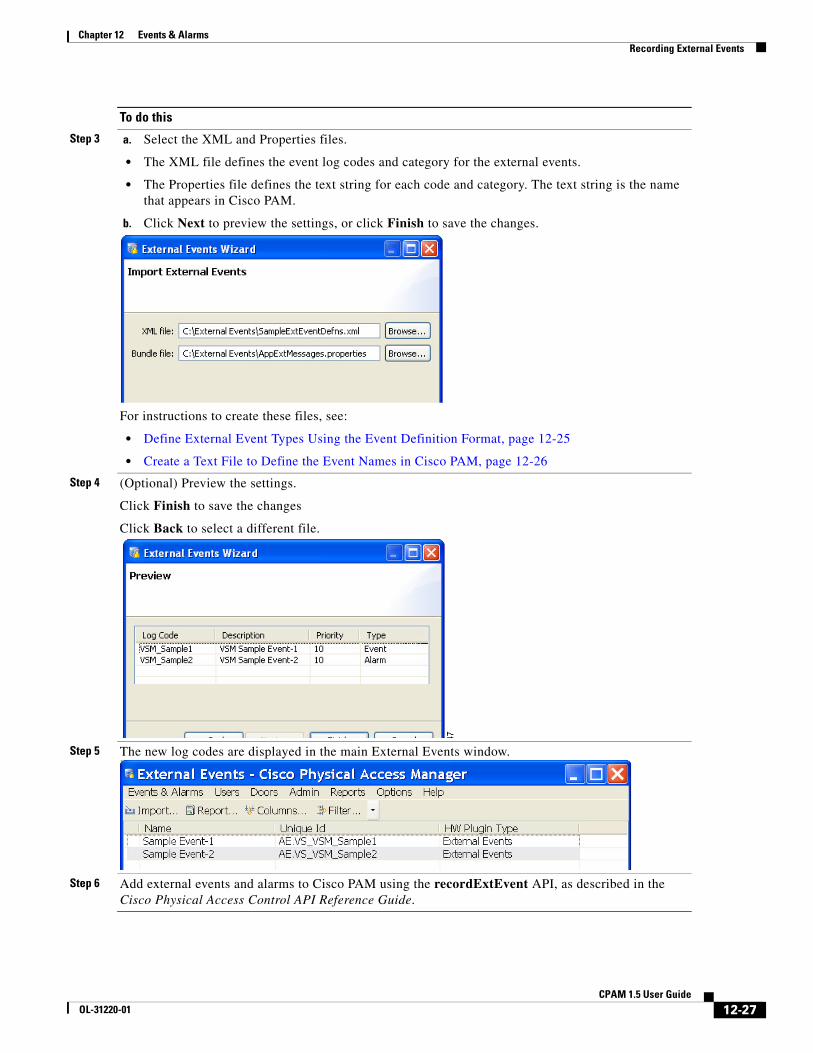
Step 3 a. Select the XML and Properties files.
• The XML file defines the event log codes and category for the external events.
• The Properties file defines the text string for each code and category. The text string is the name that appears in Cisco PAM.
b. Click Next to preview the settings, or click Finish to save the changes.
For instructions to create these files, see:
• Define External Event Types Using the Event Definition Format, page 12-25
• Create a Text File to Define the Event Names in Cisco PAM, page 12-26
Step 4 (Optional) Preview the settings.
Click Finish to save the changes
Click Back to select a different file.
Step 5 The new log codes are displayed in the main External Events window.
Step 6 Add external events and alarms to Cisco PAM using the recordExtEvent API, as described in the Cisco Physical Access Control API Reference Guide.
To do this
12-27CPAM 1.5 User Guide
OL-31220-01
Chapter 12 Events & AlarmsViewing Workstation Activity
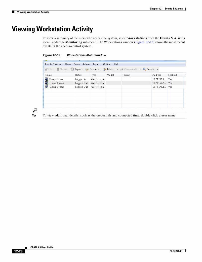
Viewing Workstation Activity To view a summary of the users who access the system, select Workstations from the Events & Alarms menu, under the Monitoring sub-menu. The Workstations window (Figure 12-13) shows the most recent events in the access-control system.
Figure 12-13 Workstations Main Window
Tip To view additional details, such as the credentials and connected time, double click a user name.
12-28CPAM 1.5 User Guide
OL-31220-01
Chapter 12 Events & AlarmsConfiguring Events and Alarms
Configuring Events and AlarmsThis section includes instructions to customize the behavior of system events. For example, you can treat an event as an alarm, suppress recording, set the event priority, define the sound played for an alarm, and other settings.
Note Event policies are executed only on the Cisco PAM server.
This section also includes instructions to limit the type of events seen by users, and configure the Alarms module to automatically open when an alarm occurs.
Contents• Modifying Default Event Policies, page 12-29
• Event Policy Manager in Cisco PAM 1.5.0, page 12-30
• Automatically Open the Alarm Window, page 12-34
• Configuring Alert Sounds, page 12-37
• Setting Event and Alarm Priorities, page 12-38
• Defining User Privileges for Editing Events, page 12-38
Tip To automatically trigger actions when an event occurs, see Chapter 13, “Configuring Automated Tasks”.
Modifying Default Event Policies Each event or alarm record includes a log code that defines the event type and actions associated with the event. The built-in event policies define inherent system behavior, such as which events are also alarms, and which events are recorded to the database (all built-in events are recorded to the database by default). These built-in policies are based on the log code only: no other criteria are used to define the event trigger.
The default event policies should be changed only if you need to change an inherent event behavior. For example:
• Whether the event is an alarm or an event.
• Whether the event is saved to the database.
• The event priority.
• The sound played when the event is triggered.
• The color shown for the event in the event modules.
When custom events are required, we recommend creating a custom event policy, as described in the following section.
12-29CPAM 1.5 User Guide
OL-31220-01
Chapter 12 Events & AlarmsConfiguring Events and Alarms
Configuring Custom Event Policies
Event policies can be configured to trigger events and alarms based on one or more conditions, such as the event type, the source device, device type, location, time of occurrence, or other factors.
• If an event policy includes more than one condition, all the conditions must match for the event to be triggered.
• If multiple events apply to an event occurrence, the most specific event policy is executed. Since only one event policy can be triggered for any event, only the most specific event is used. To determine the most specific event, the following criteria are applied in decreasing order (the criteria at the top of the list are given greater importance):
1. Log code
2. Log code category
3. Device instance
4. Device group
5. Partition
6. Hierarchical location (Building, Area, etc.)
7. Device type
8. Time schedule
9. Invert time schedule (That is, “Not in” time schedule)
Examples
• If one event policy is based on a log code (such as Door Forced Open) and a second event policy uses the same log code in combination with other criteria (such as Time schedule), then the second event policy is selected.
• If one event policy is based on a device type, and a second is based on a device instance, then the device instance event prevails since it is higher in the list of criteria.
• If two event policies are based on the same time schedule, but the first event defines During time schedule and the second event defines Not during time schedule, the first one event policy is used since During time schedule is higher in the list.
• If one event policy is based on a log code and a second policy is based on a collection of log codes and a location, all events in that location will use the second policy. Events from other locations will use the first policy.
Event Policy Manager in Cisco PAM 1.5.0If the profile enhancement feature is set in the system configuration settings(Data Entry/Validation - Login, page 17-10), you need to remember the following points while creating/editing event policies :
• A location-restricted user will not be able to edit default event policy rules.
• When a location-restricted user creates a new rule, by default the Hierarchical location field is auto-populated.
• The new rule will be applied only to devices belonging to the user’s location.
• When a location-restricted user creates an event policy it also applies to the unprivileged child locations under the location-restricted user.
12-30CPAM 1.5 User Guide
OL-31220-01
Chapter 12 Events & AlarmsConfiguring Events and Alarms
• Location-restricted users cannot filter devices of their location while creating an event policy.
Note These points are applicable only when the profile enhancement feature is set in the System Configuration of the Cisco PAM. Otherwise the Cisco PAM appliance retains its behavior as in the previous version(1.3).
To modify event policies, do the following:
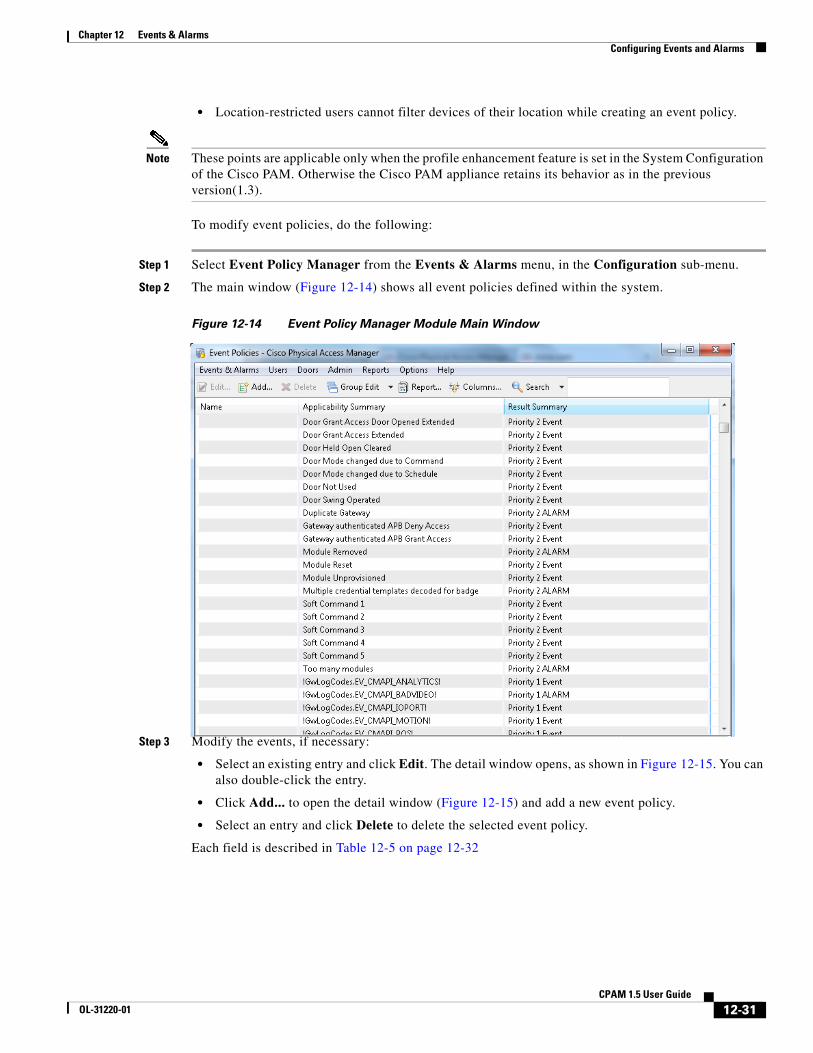
Step 1 Select Event Policy Manager from the Events & Alarms menu, in the Configuration sub-menu.
Step 2 The main window (Figure 12-14) shows all event policies defined within the system.
Figure 12-14 Event Policy Manager Module Main Window
Step 3 Modify the events, if necessary:
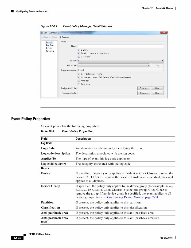
• Select an existing entry and click Edit. The detail window opens, as shown in Figure 12-15. You can also double-click the entry.
• Click Add... to open the detail window (Figure 12-15) and add a new event policy.
• Select an entry and click Delete to delete the selected event policy.
Each field is described in Table 12-5 on page 12-32
12-31CPAM 1.5 User Guide
OL-31220-01
Chapter 12 Events & AlarmsConfiguring Events and Alarms
Figure 12-15 Event Policy Manager Detail Window
Event Policy Properties
An event policy has the following properties:
Table 12-5 Event Policy Properties
Field DescriptionLog Code
Log Code An abbreviated code uniquely identifying the event.
Log code description The description associated with the log code.
Applies To The type of event this log code applies to.
Log code category The category associated with the log code.
Device
Device If specified, the policy only applies to the device. Click Choose to select the device. Click Clear to remove the device. If no device is specified, the event applies to all devices.
Device Group If specified, the policy only applies to the device group (for example: Door, Gateway, or Reader). Click Choose to select the group. Click Clear to remove the group. If no device group is specified, the event applies to all device groups. See also Configuring Device Groups, page 7-34.
Partition If present, the policy only applies to this partition.
Classification If present, the policy only applies to this classification.
Anti-passback area If present, the policy only applies to this anti-passback area.
Anti-passback area (exit)
If present, the policy only applies to this anti-passback area exit.
12-32CPAM 1.5 User Guide
OL-31220-01
Chapter 12 Events & AlarmsConfiguring Events and Alarms
Entrance If present, the policy only applies to this entrance.
Zone If present, the policy only applies to this zone.
Hierarchical location If present, the policy only applies to the doors in this location.
Device type If present, the policy only applies to devices of this type.
Time Schedule
Any time Generate events at all times and dates.
During time schedule Generate events only during the specified Time schedule.
Not during time schedule
Do not generate events during the specified Time schedule. Generate events at all times outside the specified Time schedule.
Time schedule Specifies the time schedule used for event policies. See Configuring Time Schedules, page 12-34 for more information.
Other
Is Alarm Specifies if events with this log code will be recorded as an alarm. Alarms are shown in the Alarms module.
Is Recorded Specifies if events with this log code will be recorded to the database. If unchecked, there is no record of these events occurring. This should only be unchecked by advanced users under the advice of Cisco technical support.
Priority A priority used for sorting events and alarms. Positive priorities are above normal priority, while negative priorities are below normal priority. Zero is normal.
Alert Sound The sound to be played, if Is Alarm is checked. Available alert sounds are managed in Configuring Alert Sounds, page 12-37. Click Play to preview the alarm sound.
Background color The color of the event entry. Click Choose to select a color. Click Clear to restore the default white background.
Foreground color The color of the event text. Click Choose to select a color. Click Clear to restore the default black text.
Table 12-5 Event Policy Properties (continued)
Field Description
12-33CPAM 1.5 User Guide
OL-31220-01
Chapter 12 Events & AlarmsConfiguring Events and Alarms
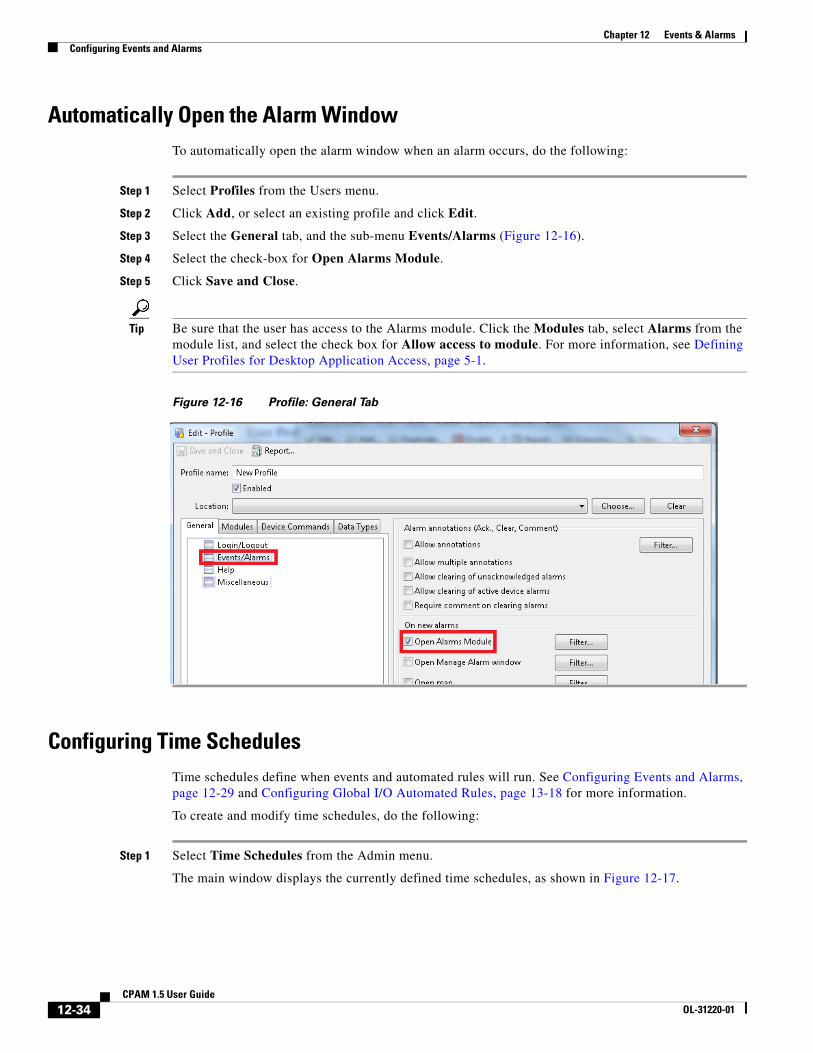
Automatically Open the Alarm WindowTo automatically open the alarm window when an alarm occurs, do the following:
Step 1 Select Profiles from the Users menu.
Step 2 Click Add, or select an existing profile and click Edit.
Step 3 Select the General tab, and the sub-menu Events/Alarms (Figure 12-16).
Step 4 Select the check-box for Open Alarms Module.
Step 5 Click Save and Close.
Tip Be sure that the user has access to the Alarms module. Click the Modules tab, select Alarms from the module list, and select the check box for Allow access to module. For more information, see Defining User Profiles for Desktop Application Access, page 5-1.
Figure 12-16 Profile: General Tab
Configuring Time SchedulesTime schedules define when events and automated rules will run. See Configuring Events and Alarms, page 12-29 and Configuring Global I/O Automated Rules, page 13-18 for more information.
To create and modify time schedules, do the following:
Step 1 Select Time Schedules from the Admin menu.
The main window displays the currently defined time schedules, as shown in Figure 12-17.
12-34CPAM 1.5 User Guide
OL-31220-01
Chapter 12 Events & AlarmsConfiguring Events and Alarms
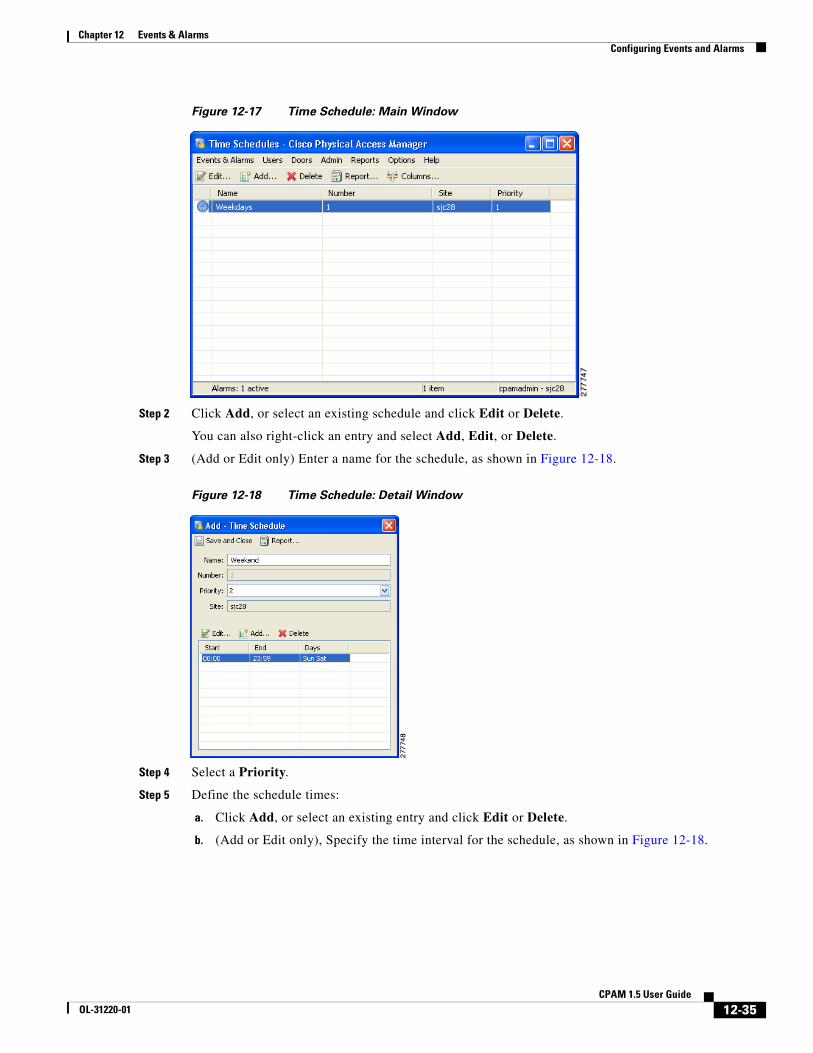
Figure 12-17 Time Schedule: Main Window
Step 2 Click Add, or select an existing schedule and click Edit or Delete.
You can also right-click an entry and select Add, Edit, or Delete.
Step 3 (Add or Edit only) Enter a name for the schedule, as shown in Figure 12-18.
Figure 12-18 Time Schedule: Detail Window
Step 4 Select a Priority.
Step 5 Define the schedule times:
a. Click Add, or select an existing entry and click Edit or Delete.
b. (Add or Edit only), Specify the time interval for the schedule, as shown in Figure 12-18.
12-35CPAM 1.5 User Guide
OL-31220-01
Chapter 12 Events & AlarmsConfiguring Events and Alarms
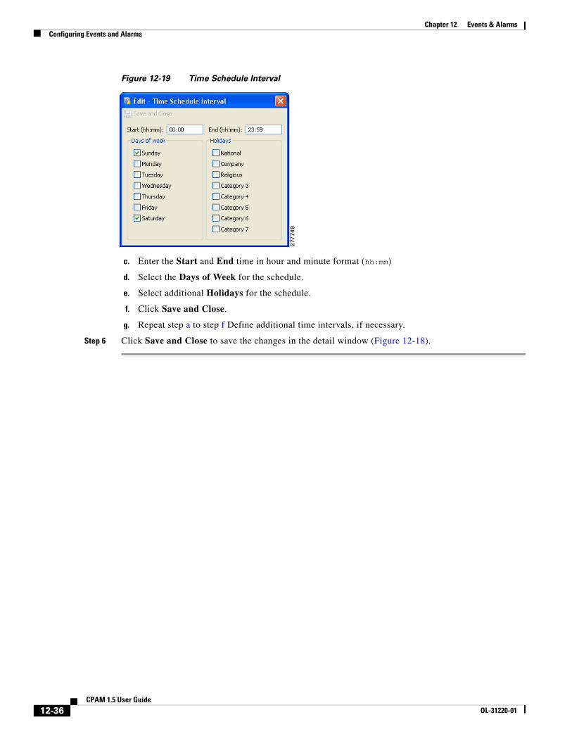
Figure 12-19 Time Schedule Interval
c. Enter the Start and End time in hour and minute format (hh:mm)
d. Select the Days of Week for the schedule.
e. Select additional Holidays for the schedule.
f. Click Save and Close.
g. Repeat step a to step f Define additional time intervals, if necessary.
Step 6 Click Save and Close to save the changes in the detail window (Figure 12-18).
12-36CPAM 1.5 User Guide
OL-31220-01
Chapter 12 Events & AlarmsConfiguring Events and Alarms
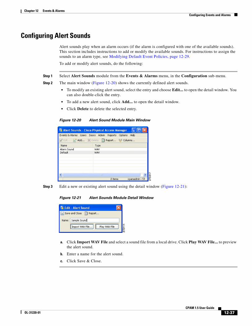
Configuring Alert Sounds Alert sounds play when an alarm occurs (if the alarm is configured with one of the available sounds). This section includes instructions to add or modify the available sounds. For instructions to assign the sounds to an alarm type, see Modifying Default Event Policies, page 12-29.
To add or modify alert sounds, do the following:
Step 1 Select Alert Sounds module from the Events & Alarms menu, in the Configuration sub-menu.
Step 2 The main window (Figure 12-20) shows the currently defined alert sounds.
• To modify an existing alert sound, select the entry and choose Edit... to open the detail window. You can also double-click the entry.
• To add a new alert sound, click Add... to open the detail window.
• Click Delete to delete the selected entry.
Figure 12-20 Alert Sound Module Main Window
Step 3 Edit a new or existing alert sound using the detail window (Figure 12-21):
Figure 12-21 Alert Sounds Module Detail Window
a. Click Import WAV File and select a sound file from a local drive. Click Play WAV File... to preview the alert sound.
b. Enter a name for the alert sound.
c. Click Save & Close.
12-37CPAM 1.5 User Guide
OL-31220-01
Chapter 12 Events & AlarmsConfiguring Events and Alarms
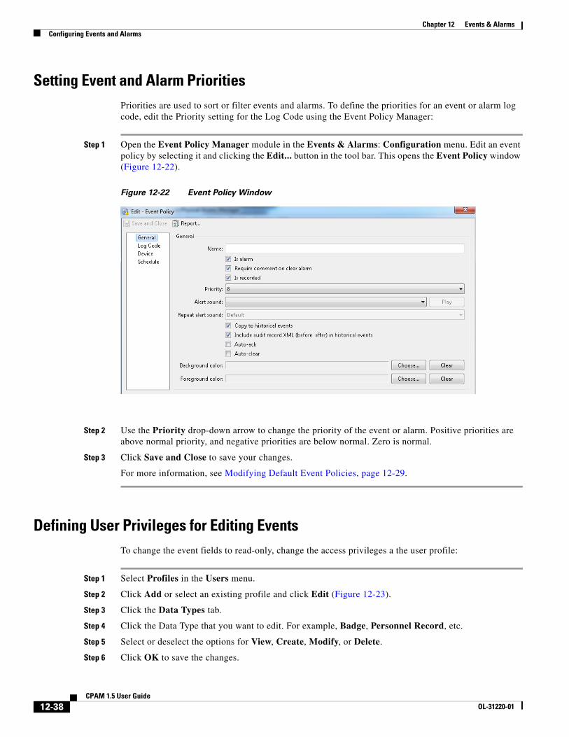
Setting Event and Alarm PrioritiesPriorities are used to sort or filter events and alarms. To define the priorities for an event or alarm log code, edit the Priority setting for the Log Code using the Event Policy Manager:
Step 1 Open the Event Policy Manager module in the Events & Alarms: Configuration menu. Edit an event policy by selecting it and clicking the Edit... button in the tool bar. This opens the Event Policy window (Figure 12-22).
Figure 12-22 Event Policy Window
Step 2 Use the Priority drop-down arrow to change the priority of the event or alarm. Positive priorities are above normal priority, and negative priorities are below normal. Zero is normal.
Step 3 Click Save and Close to save your changes.
For more information, see Modifying Default Event Policies, page 12-29.
Defining User Privileges for Editing EventsTo change the event fields to read-only, change the access privileges a the user profile:
Step 1 Select Profiles in the Users menu.
Step 2 Click Add or select an existing profile and click Edit (Figure 12-23).
Step 3 Click the Data Types tab.
Step 4 Click the Data Type that you want to edit. For example, Badge, Personnel Record, etc.
Step 5 Select or deselect the options for View, Create, Modify, or Delete.
Step 6 Click OK to save the changes.
12-38CPAM 1.5 User Guide
OL-31220-01

Chapter 12 Events & AlarmsConfiguring Events and Alarms
Figure 12-23 Selecting Editable Fields in the Profiles Module
12-39CPAM 1.5 User Guide
OL-31220-01
Chapter 12 Events & AlarmsUsing Graphic Maps
Using Graphic Maps Graphic Maps provide a visual representation of the devices available in a location. Icons representing the devices provide real-time status and alarms information, and allow the user to trigger actions such as viewing live video or denying access to a door. Automated rules can also be invoked, and icons representing a location provide status and alarm summary for all the devices assigned to that location.
Graphic Maps in Cisco PAM 1.5.0If the profile enhancement feature is set in the system configuration settings(Data Entry/Validation - Login, page 17-10), the following changes are impacted in this module:
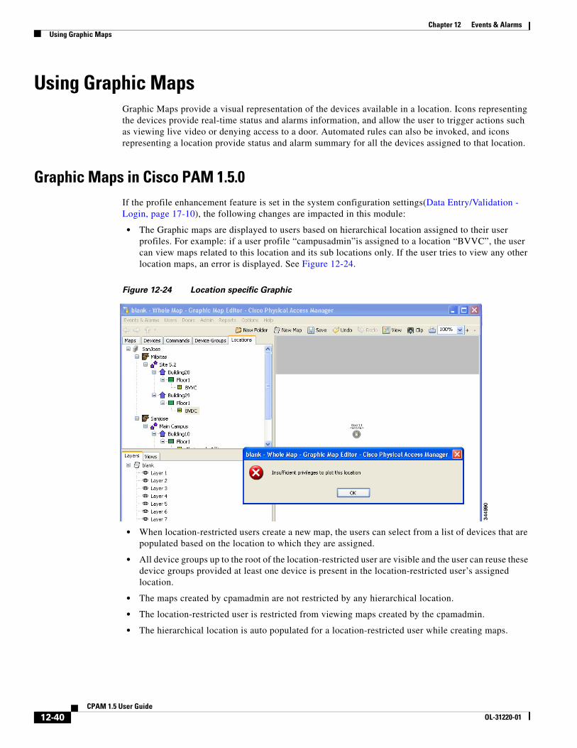
• The Graphic maps are displayed to users based on hierarchical location assigned to their user profiles. For example: if a user profile “campusadmin”is assigned to a location “BVVC”, the user can view maps related to this location and its sub locations only. If the user tries to view any other location maps, an error is displayed. See Figure 12-24.
Figure 12-24 Location specific Graphic
• When location-restricted users create a new map, the users can select from a list of devices that are populated based on the location to which they are assigned.
• All device groups up to the root of the location-restricted user are visible and the user can reuse these device groups provided at least one device is present in the location-restricted user’s assigned location.
• The maps created by cpamadmin are not restricted by any hierarchical location.
• The location-restricted user is restricted from viewing maps created by the cpamadmin.
• The hierarchical location is auto populated for a location-restricted user while creating maps.
12-40CPAM 1.5 User Guide
OL-31220-01
Chapter 12 Events & AlarmsUsing Graphic Maps
• When the cpamadmin removes a location from the location-restricted user’s hierarchy, all devices of that location is removed automatically. However if any device commands relating to these devices are present, then it requires manual removal, so the cpamadmin should ensure that they remove all associated devices/commands (manually) along with the location.
Note These points are applicable only when the Profile enhancement feature is set in the System Configuration of the Cisco PAM. Otherwise the Cisco PAM appliance retains its behavior as in the previous version(1.3)
The followings sections describes the map viewer, and the used to create the maps:
• Graphic Maps Viewer
• Graphic Map Editor
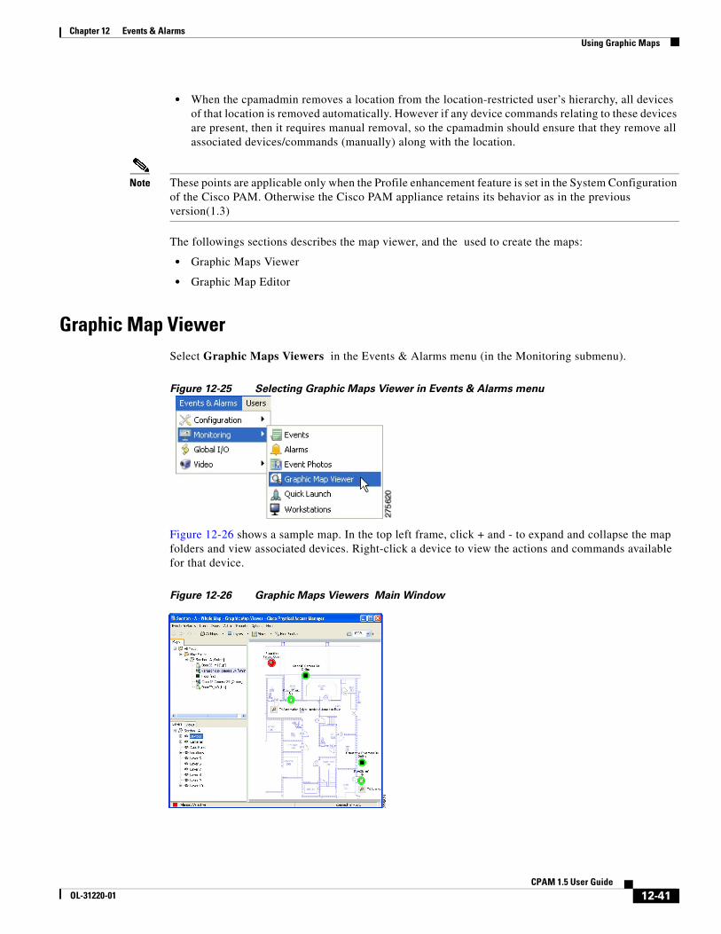
Graphic Map ViewerSelect Graphic Maps Viewers in the Events & Alarms menu (in the Monitoring submenu).
Figure 12-25 Selecting Graphic Maps Viewer in Events & Alarms menu
Figure 12-26 shows a sample map. In the top left frame, click + and - to expand and collapse the map folders and view associated devices. Right-click a device to view the actions and commands available for that device.
Figure 12-26 Graphic Maps Viewers Main Window
12-41CPAM 1.5 User Guide
OL-31220-01
Chapter 12 Events & AlarmsUsing Graphic Maps
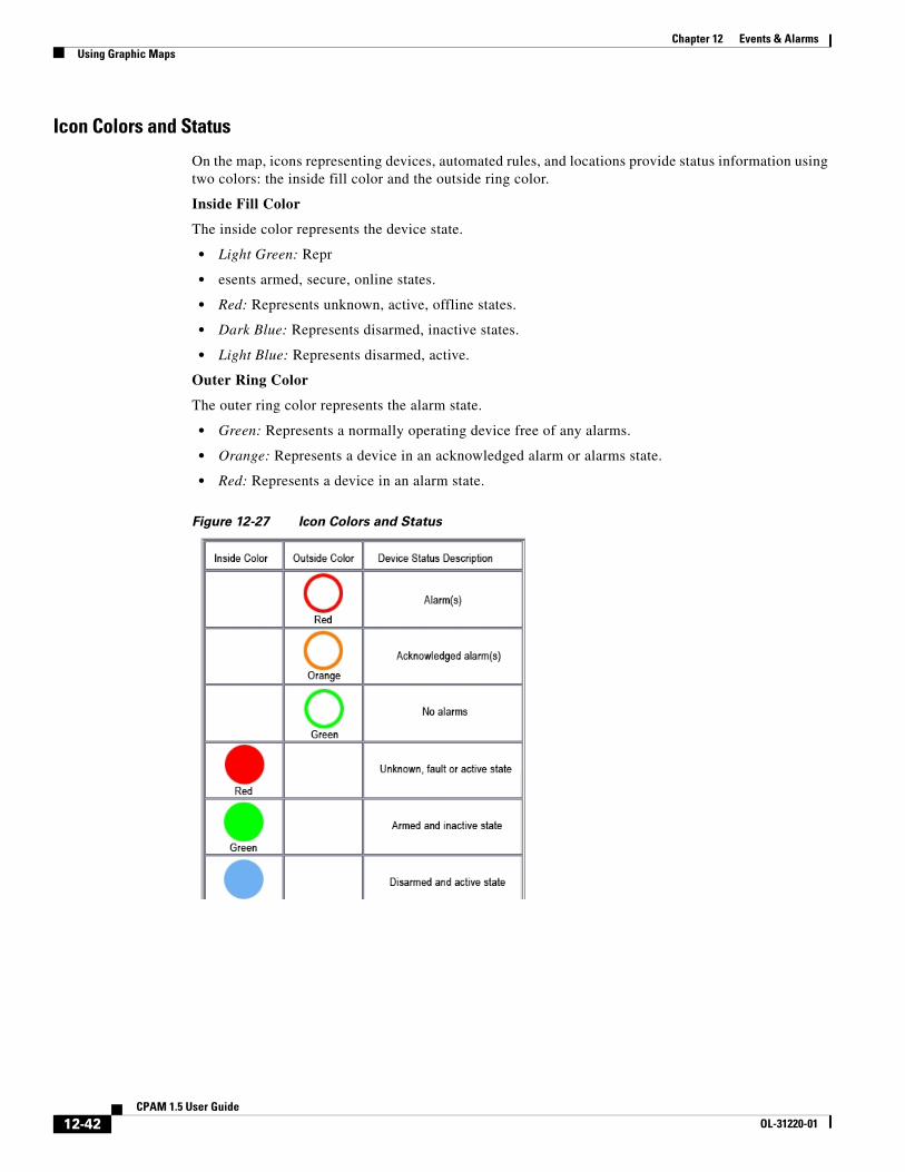
Icon Colors and Status
On the map, icons representing devices, automated rules, and locations provide status information using two colors: the inside fill color and the outside ring color.
Inside Fill Color
The inside color represents the device state.
• Light Green: Repr
• esents armed, secure, online states.
• Red: Represents unknown, active, offline states.
• Dark Blue: Represents disarmed, inactive states.
• Light Blue: Represents disarmed, active.
Outer Ring Color
The outer ring color represents the alarm state.
• Green: Represents a normally operating device free of any alarms.
• Orange: Represents a device in an acknowledged alarm or alarms state.
• Red: Represents a device in an alarm state.
Figure 12-27 Icon Colors and Status
12-42CPAM 1.5 User Guide
OL-31220-01
Chapter 12 Events & AlarmsUsing Graphic Maps
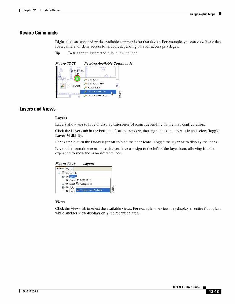
Device Commands
Right-click an icon to view the available commands for that device. For example, you can view live video for a camera, or deny access for a door, depending on your access privileges.
Tip To trigger an automated rule, click the icon.
Figure 12-28 Viewing Available Commands
Layers and Views
Layers
Layers allow you to hide or display categories of icons, depending on the map configuration.
Click the Layers tab in the bottom left of the window, then right click the layer title and select Toggle Layer Visibility.
For example, turn the Doors layer off to hide the door icons. Toggle the layer on to display the icons.
Layers that contain one or more devices have a + sign to the left of the layer icon, allowing it to be expanded to show the associated devices.
Figure 12-29 Layers
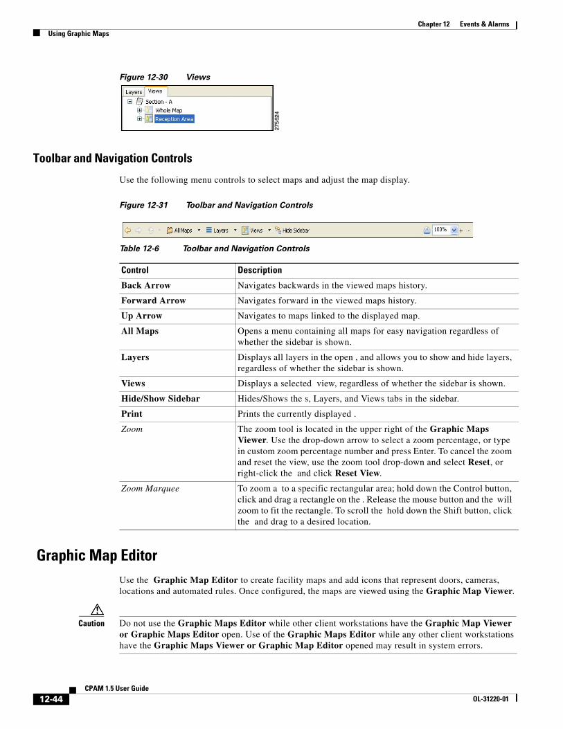
Views
Click the Views tab to select the available views. For example, one view may display an entire floor plan, while another view displays only the reception area.
12-43CPAM 1.5 User Guide
OL-31220-01
Chapter 12 Events & AlarmsUsing Graphic Maps
Figure 12-30 Views
Toolbar and Navigation Controls
Use the following menu controls to select maps and adjust the map display.
Figure 12-31 Toolbar and Navigation Controls
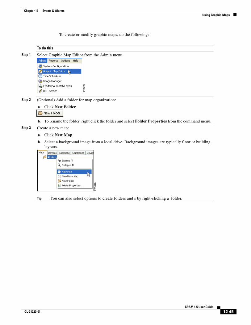
Graphic Map EditorUse the Graphic Map Editor to create facility maps and add icons that represent doors, cameras, locations and automated rules. Once configured, the maps are viewed using the Graphic Map Viewer.
Caution Do not use the Graphic Maps Editor while other client workstations have the Graphic Map Viewer or Graphic Maps Editor open. Use of the Graphic Maps Editor while any other client workstations have the Graphic Maps Viewer or Graphic Map Editor opened may result in system errors.
Table 12-6 Toolbar and Navigation Controls
Control Description
Back Arrow Navigates backwards in the viewed maps history.
Forward Arrow Navigates forward in the viewed maps history.
Up Arrow Navigates to maps linked to the displayed map.
All Maps Opens a menu containing all maps for easy navigation regardless of whether the sidebar is shown.
Layers Displays all layers in the open , and allows you to show and hide layers, regardless of whether the sidebar is shown.
Views Displays a selected view, regardless of whether the sidebar is shown.
Hide/Show Sidebar Hides/Shows the s, Layers, and Views tabs in the sidebar.
Print Prints the currently displayed .
Zoom The zoom tool is located in the upper right of the Graphic Maps Viewer. Use the drop-down arrow to select a zoom percentage, or type in custom zoom percentage number and press Enter. To cancel the zoom and reset the view, use the zoom tool drop-down and select Reset, or right-click the and click Reset View.
Zoom Marquee To zoom a to a specific rectangular area; hold down the Control button, click and drag a rectangle on the . Release the mouse button and the will zoom to fit the rectangle. To scroll the hold down the Shift button, click the and drag to a desired location.
12-44CPAM 1.5 User Guide
OL-31220-01
Chapter 12 Events & AlarmsUsing Graphic Maps
To create or modify graphic maps, do the following:
To do this
Step 1 Select Graphic Map Editor from the Admin menu.
Step 2 (Optional) Add a folder for map organization:
a. Click New Folder.
b. To rename the folder, right click the folder and select Folder Properties from the command menu.
Step 3 Create a new map:
a. Click New Map.
b. Select a background image from a local drive. Background images are typically floor or building layouts.
Tip You can also select options to create folders and s by right-clicking a folder.
12-45CPAM 1.5 User Guide
OL-31220-01
Chapter 12 Events & AlarmsUsing Graphic Maps
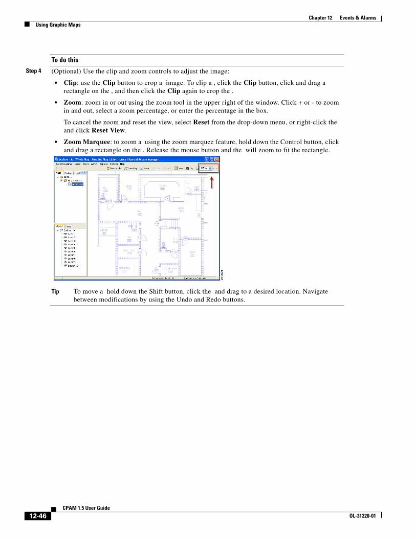
Step 4 (Optional) Use the clip and zoom controls to adjust the image:
• Clip: use the Clip button to crop a image. To clip a , click the Clip button, click and drag a rectangle on the , and then click the Clip again to crop the .
• Zoom: zoom in or out using the zoom tool in the upper right of the window. Click + or - to zoom in and out, select a zoom percentage, or enter the percentage in the box.
To cancel the zoom and reset the view, select Reset from the drop-down menu, or right-click the and click Reset View.
• Zoom Marquee: to zoom a using the zoom marquee feature, hold down the Control button, click and drag a rectangle on the . Release the mouse button and the will zoom to fit the rectangle.
Tip To move a hold down the Shift button, click the and drag to a desired location. Navigate between modifications by using the Undo and Redo buttons.
To do this
12-46CPAM 1.5 User Guide
OL-31220-01
Chapter 12 Events & AlarmsUsing Graphic Maps
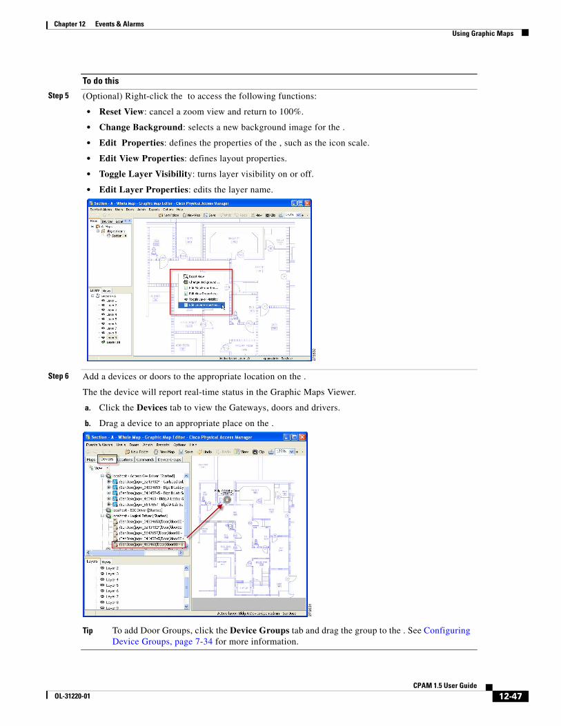
Step 5 (Optional) Right-click the to access the following functions:
• Reset View: cancel a zoom view and return to 100%.
• Change Background: selects a new background image for the .
• Edit Properties: defines the properties of the , such as the icon scale.
• Edit View Properties: defines layout properties.
• Toggle Layer Visibility: turns layer visibility on or off.
• Edit Layer Properties: edits the layer name.
Step 6 Add a devices or doors to the appropriate location on the .
The the device will report real-time status in the Graphic Maps Viewer.
a. Click the Devices tab to view the Gateways, doors and drivers.
b. Drag a device to an appropriate place on the .
Tip To add Door Groups, click the Device Groups tab and drag the group to the . See Configuring Device Groups, page 7-34 for more information.
To do this
12-47CPAM 1.5 User Guide
OL-31220-01
Chapter 12 Events & AlarmsUsing Graphic Maps
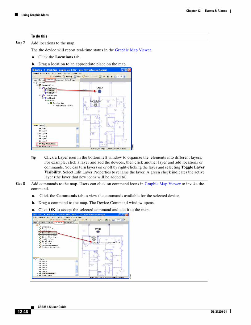
Step 7 Add locations to the map.
The the device will report real-time status in the Graphic Map Viewer.
a. Click the Locations tab.
b. Drag a location to an appropriate place on the map.
Tip Click a Layer icon in the bottom left window to organize the elements into different layers. For example, click a layer and add the devices, then click another layer and add locations or commands. You can turn layers on or off by right-clicking the layer and selecting Toggle Layer Visibility. Select Edit Layer Properties to rename the layer. A green check indicates the active layer (the layer that new icons will be added to).
Step 8 Add commands to the map. Users can click on command icons in Graphic Map Viewer to invoke the command.
a. Click the Commands tab to view the commands available for the selected device.
b. Drag a command to the map. The Device Command window opens.
c. Click OK to accept the selected command and add it to the map.
To do this
12-48CPAM 1.5 User Guide
OL-31220-01
Chapter 12 Events & AlarmsUsing Graphic Maps
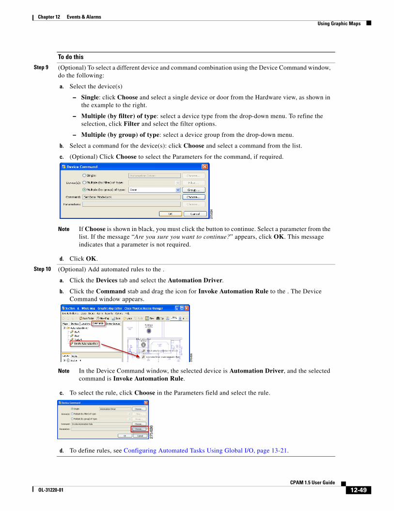
Step 9 (Optional) To select a different device and command combination using the Device Command window, do the following:
a. Select the device(s)
– Single: click Choose and select a single device or door from the Hardware view, as shown in the example to the right.
– Multiple (by filter) of type: select a device type from the drop-down menu. To refine the selection, click Filter and select the filter options.
– Multiple (by group) of type: select a device group from the drop-down menu.
b. Select a command for the device(s): click Choose and select a command from the list.
c. (Optional) Click Choose to select the Parameters for the command, if required.
Note If Choose is shown in black, you must click the button to continue. Select a parameter from the list. If the message “Are you sure you want to continue?” appears, click OK. This message indicates that a parameter is not required.
d. Click OK.
Step 10 (Optional) Add automated rules to the .
a. Click the Devices tab and select the Automation Driver.
b. Click the Command stab and drag the icon for Invoke Automation Rule to the . The Device Command window appears.
Note In the Device Command window, the selected device is Automation Driver, and the selected command is Invoke Automation Rule.
c. To select the rule, click Choose in the Parameters field and select the rule.
d. To define rules, see Configuring Automated Tasks Using Global I/O, page 13-21.
To do this
12-49CPAM 1.5 User Guide
OL-31220-01
Chapter 12 Events & AlarmsUsing Graphic Maps
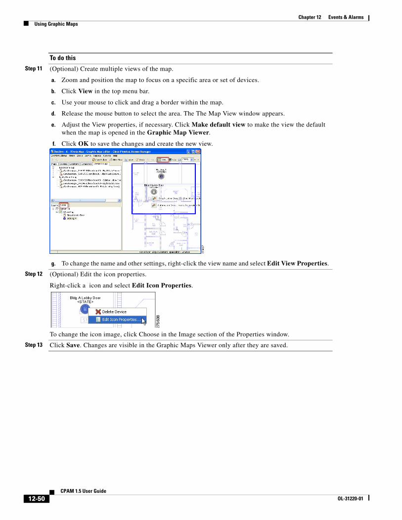
Step 11 (Optional) Create multiple views of the map.
a. Zoom and position the map to focus on a specific area or set of devices.
b. Click View in the top menu bar.
c. Use your mouse to click and drag a border within the map.
d. Release the mouse button to select the area. The The Map View window appears.
e. Adjust the View properties, if necessary. Click Make default view to make the view the default when the map is opened in the Graphic Map Viewer.
f. Click OK to save the changes and create the new view.
g. To change the name and other settings, right-click the view name and select Edit View Properties.
Step 12 (Optional) Edit the icon properties.
Right-click a icon and select Edit Icon Properties.
To change the icon image, click Choose in the Image section of the Properties window.
Step 13 Click Save. Changes are visible in the Graphic Maps Viewer only after they are saved.
To do this
12-50CPAM 1.5 User Guide
OL-31220-01
Chapter 12 Events & AlarmsBacking Up and Archiving Events
Backing Up and Archiving EventsYou can include or exclude events from system backups. You can also prune and archive old events to remove them from the main database. The following topics provide more information:
• “Including Events In System Backups” section on page 12-51
• “Pruning and Archiving Old Events” section on page 12-51
• Creating Reports from Pruned Events, page 12-52
Including Events In System BackupsEvents can either be included or excluded from system backups, as described in the “Backing up the Cisco PAM Database” section on page A-1. Including events allows you to restore those events along with other data and configurations. However, the backup process will take longer and the backup file will be larger.
Excluding events from a system backup reduces the size of the backup file, and the time required to complete the backup process.
Pruning and Archiving Old EventsAs an alternative to backing up all events, you can prune and archive old events.
• Pruned events are removed from the live database table and placed in a separate database table, allowing you to reduce the size of the main database while keeping them accessible on the Cisco PAM system. Pruned events are not visible in Events & Alarms, but are included in reports. Pruned events are also included in system backups.
• Archived events are removed from all Cisco PAM database tables and copied to a compressed file. The file includes a password-protected SQL script, and can be run on an offline database to view the purged events. Archived events are not visible in the Events & Alarms listings or Reports, and are not included in system backups.
Archiving historic events improves system performance and simplifies monitoring since only the latest, most relevant, events and alarms are displayed. System backup file sizes are also reduced. In addition, the historical event records are self-contained. Referenced objects, such as a person's name and card number, are retained even if the original record is deleted. Reports on historical events can also span a much longer time range than is normally possible for live events.
Archived event files can be restored to the Cisco PAM database, if necessary, or used by other applications to view old events or run reports. See the “Creating Reports from Pruned Events” section on page 12-52.
See the “Archiving Historical Events” section on page 3-24 for more information.
12-51CPAM 1.5 User Guide
OL-31220-01
Chapter 12 Events & AlarmsBacking Up and Archiving Events
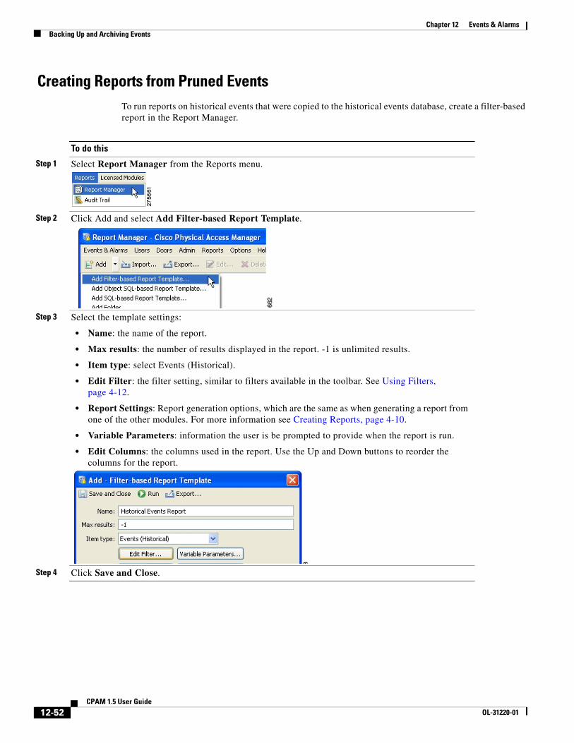
Creating Reports from Pruned EventsTo run reports on historical events that were copied to the historical events database, create a filter-based report in the Report Manager.
To do this
Step 1 Select Report Manager from the Reports menu.
Step 2 Click Add and select Add Filter-based Report Template.
Step 3 Select the template settings:
• Name: the name of the report.
• Max results: the number of results displayed in the report. -1 is unlimited results.
• Item type: select Events (Historical).
• Edit Filter: the filter setting, similar to filters available in the toolbar. See Using Filters, page 4-12.
• Report Settings: Report generation options, which are the same as when generating a report from one of the other modules. For more information see Creating Reports, page 4-10.
• Variable Parameters: information the user is be prompted to provide when the report is run.
• Edit Columns: the columns used in the report. Use the Up and Down buttons to reorder the columns for the report.
Step 4 Click Save and Close.
12-52CPAM 1.5 User Guide
OL-31220-01