Embed Size (px)
Citation preview

GUIDE TO UNDERSTANDING AS/NZS 4058:2007
CPAA DESIGN MANUAL
Concrete Pipe Associationof Australasia
Concrete Pipe Associationof Australasia
Guide to Understanding AS/NZS 4058:2007
Concrete Pipe Associationof Australasia
www.cpaa.asn.au

GUIDE TO UNDERSTANDING AS/NZS 4058:2007
1
Concrete Pipe Associationof Australasia
Concrete Pipe Associationof Australasia
Guide to
Understanding
AS/NZS 4058:2007
First edition – December 2013
GUIDE TO UNDERSTANDING AS/NZS 4058:2007
2
Contents
INTRODUCTION 3
PREFACE 4
C1 SCOPE & GENERAL 4
C2 MATERIALS 7
C3 MANUFACTURE, HANDLING AND STORAGE 8
C4 PERFORMANCE TEST 16
C5 COMPLIANCE WITH PERFORMANCE REQUIREMENTS 17
APPENDICES 19

CONCRETE PIPE ASSOCIATION OF AUSTRALASIA
3
Introduction
Concrete pipes were first manufactured in Australia and New Zealand more than 100 years ago. Following this, two unique horizontal casting processes (centrifugal wet spinning and roller
suspension) were developed in the early 1900s and these became the driving force of the concrete pipe manufacturing industry in Australasia. It is the technology employed in these processes, along with more recently introduced vertical casting methods, which has been a major propagator of efficiency and durability of concrete pipe in this region and has allowed for consistent quality and in-service performance of these pipes since over time.
Following the success of the early innovators, the first Standard for concrete pipe, AS A35 Concrete Drainage Pipes (Pre-cast), was published in 1937. Its purpose was to establish a range of process requirements and a regime of tests that would result in concrete pipes being made that were specifically fit for the purpose of sewage, industrial waste and stormwater drainage. Since this time Standards Australia and Standards New Zealand have been instrumental in setting and maintaining uniformly high standards of manufacture in the industry. This has resulted in many years of excellent performance of thin walled, high quality concrete pipe.
In Australia, AS A35 was revised in 1957 (ASA35-1957) in response to a request from the 'Confer-ence of State Road Authorities of Australia' for the extension of the specification to include two classes of pipe having capabilities in excess of the strength specified for Class X pipe. No substantial changes were made in technical requirements. Then, in 1962, a separate pressure pipe standard AS A 124 Precast Concrete Pressure Pipes was developed. Both of these Standards were revised again in 1972 (AS 1372 Precast concrete pipes (drainage)) and 1973 (AS 1392 Precast concrete pipes (pres-sure)) respectively, before being consolidated as one standard in 1992 as AS 4058 Precast concrete pipes (pressure and non-pressure).
In New Zealand, the Australian Standard was used by industry until 1965 when NZS 2238 Precast concrete drainage pipe was introduced. This was superseded in 1977 by NZS 3107 Precast concrete drainage pip.
At the next review of AS 4058 the industry agreed that both New Zealand Standard and Australian Standard for concrete pipe should be harmonised due to many similarities.
In 2007, the Standards committee signed off on what could be considered to be the most robust standard ever produced for the production of quality concrete pipe in Australia and New Zealand – AS/NZS 4058: 2007 Precast concrete pipe (pressure and non-pressure). The main purpose of AS/NZS 4058 is to provide manufacturers with a series of guidelines that allows them to manufacture an appropriate size concrete pipe to the required strength class that will comply with the service-ability requirements outlined in the Standard.
This guide has been compiled by the Concrete Pipe Association of Australasia to assist industry stakeholders in understanding the background to various requirements and expectations that are outlined in AS/NZS 4058, and why these apply specifically to precast concrete pipes.
NOTE: All sections in this guide refer to the appropriate Section, Clause or Appendix of AS/NZS 4058:2007. Each has been prefaced by the letter 'C' in a manner similar to the reference system used in Commentaries provided by Australian and New Zealand Standards.

GUIDE TO UNDERSTANDING AS/NZS 4058:2007
4
C-PrefaceThe Preface of AS/NZS 4058 states:
'The in-service life of a pipeline installation is dependent on the pipe’s manufacture, application and installation conditions. Based on past experi-ence of concrete pipe installations, a service life of 100 years could be expected when pipes are manufactured in accordance with Standard AS/NZS 4058, and installed in accordance with AS/NZS 3725 in a normal environment and marine environ-ment as defined in the Standard AS/NZS 4058.'
This was supported by the concrete pipe industry in the 2007 review which was able to draw upon a long history of field performance and investigation of buried concrete pipe along with almost 100 years’ experience of manufacturing experience1,2,3,4,5.
It indicates that the in-service life of an installed pipeline is dependent on the pipe’s manufacture, application and installation conditions. To be more specific on these variables, this includes:
a) the quality of the pipe as manufactured
b) the suitability of the pipe for its intended use, including – (i) Pipe Diameter (ii) Load class (iii) Watertightness or pressure class (iv) Joint type.
c) the quality of the installation. (i) Initially – gradient, embedment geometry, fill treatment, pipe storage, handling (ii) Ongoing – installation conditions, embedment support
d) the external and internal environment and how they change over the service life of the pipeline.
For these reasons the Preface specifically nomi-nates that an in-service life of 100 years could be expected where:
a) concrete pipes conform to the manufacturing requirements of AS/NZS 4058
b) the installed pipe is subject to either a normal environment or marine environment as defined in AS/NZS 4058
c) installation is in accordance with AS/NZS 3725.
NOTE: There are a number of definitions of service life and design life in Australian and New Zealand Standards related to concrete, and other recognised specifications and codes. In the instance of SRCP made to AS/NZS 4058 and installed in accordance to AS/NZS 3725 it is not unreasonable to suggest that service life can be defined as 'the period in which the structure (in this instance the pipeline) is intended to remain fit for its intended purpose without any major maintenance or replacement required'. History demonstrates that this has occurred over the years, and manufacturing SRCP to the more robust Standards of today enables the expectation of an in-service life of 100 years.
C1 – Scope & GeneralC1.1 Scope The main purpose of AS/NZS 4058:2007 (the Standard) is to provide manufacturers with a series of guidelines that allows them to manufacture concrete pipe to an appropriate size and to a required strength class that will allow it to last for over 100 years when designed and installed in accordance with AS/NZS 3725:2007 Design for installation of buried concrete pipes.
The Standard is recognised as a performance based document. This means that concrete pipe manufactured to this Standard is expected to meet specific performance criterion that is correlated to the environment and service conditions the mate-rial is expected to perform in throughout its life.
To achieve this the machinery and equipment used for the manufacture of steel reinforced concrete pipe in Australia and New Zealand is character-ised by an ability to handle and compact concrete that is low in water content but high in cement or binder content, to achieve the strict performance criterion. The manufacturing methods used in the two countries include:
• centrifugal roller compaction and heavy vibratory methods• centrifugal spinning in which the water/binder
ratio of concrete is further reduced by centrifugal action• vertical dry-cast methods using rollers to compact the concrete• vertical dry-cast methods using heavy vibration
to compact the concrete.
An essential requirement for each of these manufacturing processes is the use of a low water/

CONCRETE PIPE ASSOCIATION OF AUSTRALASIA
5
binder ratio mix plus intense vibration to achieve mechanical interlock of the materials to form a pipe wall that will remain supported by the pipe mould during manufacture.
As the water/binder ratio of concrete in pipes made using these processes is low it will inher-ently achieve the required durability properties expected from the product. This combination of low water/binder ratios and high levels of compac-tion commonly achieve high concrete compressive strengths. The concrete produced has very low permeability to water and has arguably the highest level of durability that can be achieved by any commercial concrete casting process. High strength concrete with a w/b < 0.4 that is low in perme- ability is widely recognised as providing a durable long life material.
The CPAA recognises the Standard as the most appropriate specification for industry to use so that the quality of concrete pipe produced will provide a consistent material capable of demon-strating a service life of 100 years. This recognition and the requirement for a specific Standard apply-ing to concrete pipe is warranted for the following reasons:
• Pipes are produced en masse in a controlled environment to achieve specific requirements. • The equipment used is engineered to high standards that allow reliable repeatability of processes.• The technology of the casting processes
dictates that a low water binder ratio material and intense vibration are used.
• Quality verification by control of materials input, machinery maintenance and setting and a regime of performance testing of representative sampling of products produced is
the most appropriate form of Quality Assurance and Control.
• The product is made for a clearly defined end use, both with respect to support conditions and loads applied as well as the environmental exposure of the installation.
Since 1937 concrete pipe has been manufactured to the specific requirements of a performance based Australian or New Zealand Standard. Each subsequent revision of the Standard has main-tained or tightened the controls on manufacturing and product testing.
This recognition is why the Scope specifically refer-ences the application of the Standard to circular precast pipes made from concrete, and is support-ed by the two main Standards used for concrete design in Australia:
AS 3600:2009 Concrete structures – Clause 4.10.3.6 'Structural members manufactured by spinning or rolling' states that: 'Where structural members are manufactured by spinning or rolling concrete, the cover for the corrosion protection shall be as specified in the appropriate Standard. NOTE – For example, refer to AS/NZS 4058 and AS/NZS 4065.'
AS 5100.5 'Bridge Design – Concrete' Supp 1:2008 – Clause 4.10.3.5 'Structural members manufactured by spinning or rolling' states that: 'Cover requirements are given for structural appli-cations of spun or rolled concrete members. Other Standards apply to concrete pipes or culverts carrying aqueous liquids.'
C1.3 Definitions The Standard has a number of definitions with specific reference to steel reinforced concrete pipe. Some of these require further explanation to pro-vide a better understanding of these specific con-crete pipe characteristics.
C1.3.2.4 Diameter
The Standard defines four examples of diameter that are applicable to concrete pipe, yet all have subtle differences that make a difference to design and manufacture. These are:
1. Design diameter – this is the internal diame-ter nominated by the manufacturer for a speci-fied nominal size, to which specified tolerances are applied. The design diameter is typically the value used for hydraulic calculations. It usually decreases as the load or pressure class increases depending on the manufacturing process and the design requirements.
2. Internal diameter – this is the measured internal diameter of a concrete pipe after manufacture.
3. External diameter – this is the measured ex-ternal diameter of a concrete pipe after man-ufacture. The external diameter (D) is used in design calculation for loads on buried concrete pipe, as per AS/NZS 3725.

6
GUIDE TO UNDERSTANDING AS/NZS 4058:2007
4. Nominal diameter – this is a convenient round number that refers to the internal diameter and is loosely related to manufacturing dimensions. Typical nominal diameters (DN) for concrete pipe made in Australia and New Zealand are found in Table 4.2 of the Standard. It also provides the industry with consistent terminology allowing for differences in wall thicknesses and actual internal/external dimensions arising from diffe-rent manufacturing processes, designs, load class, application, cover, etc. It should also be noted that the term 'size class' is used in the Standard. The size class is based on the nomi-nal diameter (i.e. a size class of 1500 is a pipe of 1500 mm nominal diameter).
Diagram 1 – Example of the various diameter types
C1.3.2.5 Deflection
The Standard defines deflection as 'the maximum angle between two adjoining pipes that is quoted by the manufacturer as being able to be obtained without loss of joint performance for an appropri-ate service condition'.
Such deflections are sometimes required when a pipeline is required to have a curve in the line. This can be achieved using different methods.
For small deflections a rubber ring jointed pipe joint can be opened up to a recommended angle (as nominated by the manufacturer and agreed upon by the designer) which is specific to the pipe
diameter and the nominated joint gap (also known as the gap width or laying gap). This is done after jointing has been completed.
For large deflections, specially made pipes, that may include a prefabricated splay end, can be manufactured to suit the design requirements.
In practice however there are some installation considerations to take into account. In particu-lar, it is important to leave room for differential settlement that may occur following installation. If a pipe is poorly installed and is at the maximum deflection in the vertical plane, and is on the limit of being watertight, then the watertightness may be compromised after the ground settles and there is further deflection. Careful supervision and evalua-tion of future ground movements is recommended in these situations.
In all instances it is important to work with the manufacturer to understand (a) joint deflection limitations and (b) availability of the most appro-priate pipe joint type.
DIAGRAM 2 – Example of typical deflection of concrete pipe (cross section)
DIAGRAM 3 – Example of typical deflection of
concrete pipe (plan)

7
CONCRETE PIPE ASSOCIATION OF AUSTRALASIA
C1.3.2.13 Test crack
The Standard defines a test crack as 'a crack de-veloped in a pipe when the appropriate proof load has been applied and maintained in accordance with Appendix C'.
The principles of reinforced concrete design are based upon the accepted concept that cracking of the concrete is necessary to permit development of the full tensile strength of the reinforcing steel. With precast steel reinforced concrete pipe it became possible to use this characteristic as a criterion for non-destructive quality control testing. This led to the adoption of a minimum crack width as a consistent measurement of conformance for when concrete pipe is tested for strength under a sustained load.
The original crack width nominated as being acceptable under a sustained test load was 0.01 inch for cover to steel of 1 inch (i.e. 0.25 mm crack for 25 mm cover to steel) by Professor W.J. Schick of Iowa State University in the 1930s. This is still the crack width accepted for concrete pipe tested under sustained load in the USA and Canada. In Australia and New Zealand this method of meas-uring acceptability under test load has existed for over 70 years, and due to the lower cover re-quirements in the region, can be significantly smaller by comparison to other countries (i.e. the Standard nominates 0.15 mm as the maximum accepted crack width for concrete pipe designed for normal environment, where concrete cover to steel is > 10 mm and < 20 mm). (For more information go to the section referring to Appendix C of the Standard.)
C1.3.2.13 Proof load (TC)
The Standard defines proof load as 'the specified load applied to and sustained by a pipe without the appearance of cracks greater than the appro-priate test crack'.
This effectively means the specified load applied to and sustained by a pipe so that the test crack width at proof load can be measured. In practice you apply the proof load and record the test crack width. If it is ≤ 0.15 mm the pipe passes (i.e. if you cannot get a 0.15 mm crack gauge into the crack at any point along its length it passes).
The supporting strength of a buried concrete pipe-line is dependent on the structural strength of the pipe, the type of foundation, and the compaction
of the fill material adjacent to the pipe. The most common and accepted method of testing the structural strength of a concrete pipe is the proof load test. This is done by a two-edge or three-edge bearing test, both of which require concrete pipe to support a load, per linear metre, under sus-tained conditions. This is the most severe test that a concrete pipe will be subjected to as it has no lateral support and the applied forces in the test are virtually point loads.
In the Standard the appropriate proof load for each pipe diameter and class made in Australia and New Zealand is provided in Table 4.2, and the test procedure is nominated in Appendix C.
C2 – MaterialsManufacturers must have an auditable system of control that provides proof that the materials used to produce concrete pipe comply with the Standard. Section 2 nominates what these controls are for the raw materials that are typically used in concrete pipe. These controls are specific to each raw material.
C2.2 Concrete materialsThe tight controls on concrete raw materials are the first part of a multi-staged system of control re-quired where concrete pipe of predictable uniform quality is to have the potential for a service life of at least 100 years.
The extent of the control of raw materials for pipe concrete exceeds the controls for many other types of pipe materials. In these instances of other pipe materials the finished product testing is often the major control with component raw materials and manufacturing processes being less subject to veri-fication of compliance.
C2.2.6 Acid soluble chloride and sul-phate ion content
The testing of materials for compliance with the maximum values for acid-soluble chloride and sul-phate ion content (as specified in Table 2.1) should be conducted in accordance with AS 1012.20.
C2.3 ReinforcementThe requirement that all steel reinforcement shall comply with AS/NZS 4671 is another of the strict raw material controls necessary to en-

8
GUIDE TO UNDERSTANDING AS/NZS 4058:2007
sure concrete pipe as required in the field. It ensures that the reinforcement component of the product is of a known and uniform accept-able quality. The quality of the material used will also be checked when the concrete pipe is load tested during routine performance testing. As indi-cated previously other performance based products are not so restricted and can be reinforced with unspecified materials or materials that are not speci- fied as conforming to an appropriate Standard.
C2.4 Joint MaterialsThe Standard requires that all elastomeric seals or joint bands shall comply with the relevant AS 1646: 2007 section, or where no such requirement exists, an appropriate current international Standard. Ad-ditionally, AS 1646:2007 specifies that elastomeric seals shall also comply with the relevant part of AS 681. The AS 681 suite is a cloned version of international Standard EN 681 Elastomeric seals – Material requirements for pipe joint seals used in water and drainage applications. AS 681 pro-vides detailed requirements for specific elastomeric products. These Standards have been specified to ensure that the quality of the seal incorporated is appropriate for the intended application and expected service life of the installed pipeline.
The service life expectancy of elastomeric seals is expected to be in excess of 100 years6,7 provided the seal is not detrimentally affected by bad work-manship during installation or by later environmen-tal factors that could not have been considered at the time of design.
To maximise the performance of the joint and the expected service life of the seal it is important that:
a) the selected elastomeric seal material is appropriate for the intended application of the pipeline
b) all seals used in the installation are packaged, stored and handled in accordance with the seal manufacturers’ requirements prior to installation
c) the pipe joint is assembled using the specified seal size and elastomeric material, in accord-ance with the pipe manufacturers specified jointing procedure.
Elastomeric seal manufacturers are able to provide guidance on the selection and specification of elas-tomeric types for specific applications.
C3 – Manufacture,Handing and StorageManufacturers must have an auditable system of control that provides proof that concrete pipe manufacturing, handling and storage comply with the Standard. Section 3 of the Standard nominates what these controls are with specific reference to design details, dimension and tolerance, workman-ship and finish, and handling, storage and trans-portation. The items below explain what some of these controls include and why they are important.
C3.2.1 Joints
This clause distinguishes between the assembled joint requirements for rigid joints and flexible joints. Figure 1.1 in the Standard provides typical examples of the various concrete pipe joint types available. The traditional classification of rigid and flexible joints is being replaced by the terms non- watertight and watertight, and these can be cate-gorised with respect to the Standard as follows:
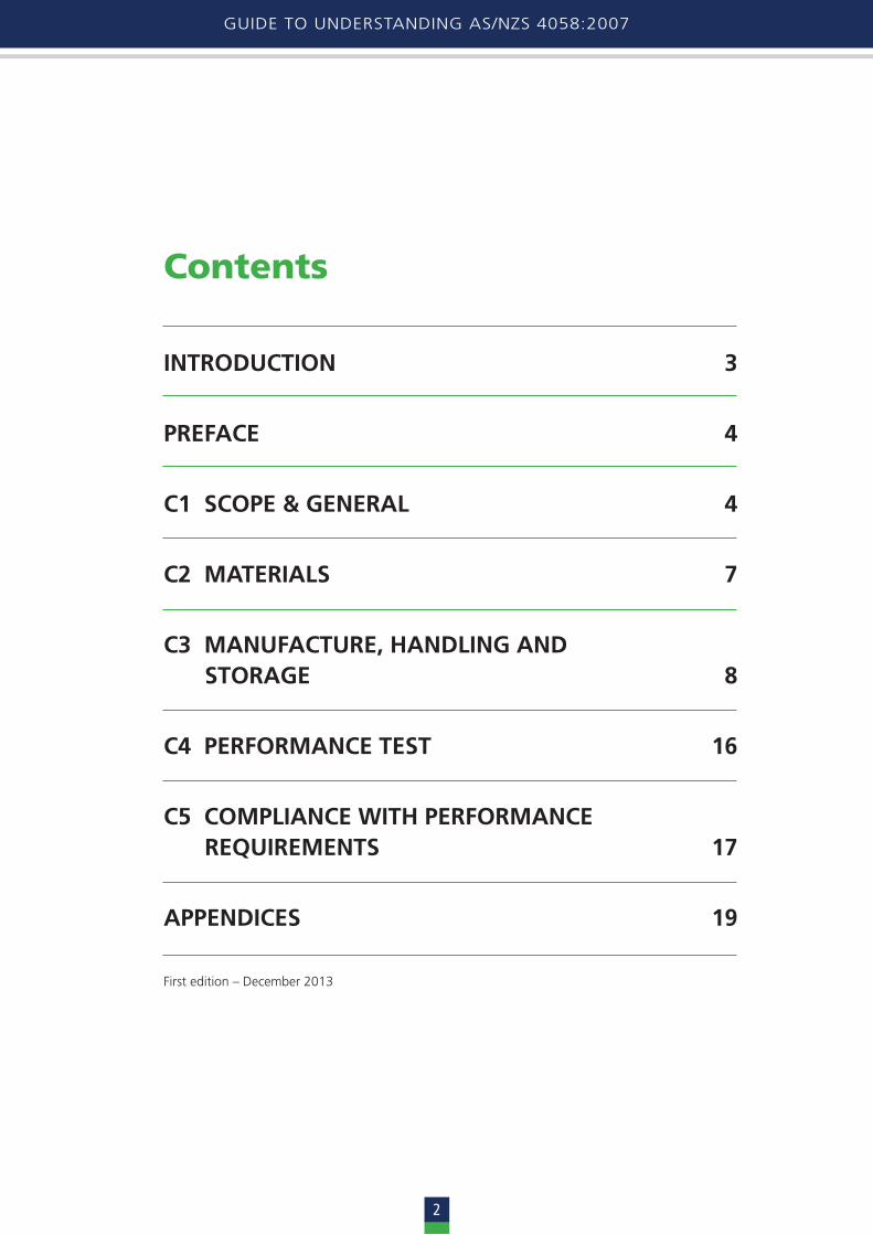
a) Non-watertight joints include: (i) External flush joint (smaller diameters) (ii) Internal flush joint (larger accessible diameters) (iii) Butt joint (iv) Spigot and socket joint (without rubber ring, suitable for mortaring).
These joints are suitable for non-watertight appli-cations such as typical stormwater drainage and the following applications where additional atten-tion is given to providing a form of seal at the joint:
• non-pressure applications with the use of suitable sealing material (i.e. service duct applications)
• flush joint alternatives provide a recess in the joint profile that can be mortared should it be considered useful. Flush and butt joints with external elastomeric sealing band (i.e. to prevent infiltration of backfill and accommodate minor deflections resulting from pipeline movement)
• butt jointed jacking pipe with 'cast in' or 'float-ing' external steel band.
To ensure that non-watertight joints are suited for their intended purpose it is important that the dimensional accuracy of the ends of each pipe conform to the requirements as specified in Clause 3.3 of the Standard (end squareness, wall thick-ness, internal diameter and external diameter).
9
CONCRETE PIPE ASSOCIATION OF AUSTRALASIA
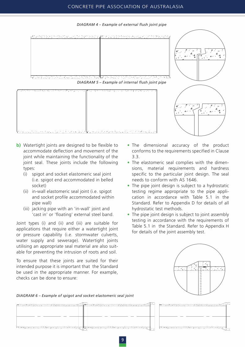
b) Watertight joints are designed to be flexible to accommodate deflection and movement of the joint while maintaining the functionality of the joint seal. These joints include the following types:
(i) spigot and socket elastomeric seal joint (i.e. spigot end accommodated in belled socket) (ii) in-wall elastomeric seal joint (i.e. spigot and socket profile accommodated within pipe wall) (iii) jacking pipe with an 'in-wall' joint and 'cast in' or 'floating' external steel band.
Joint types (i) and (ii) and (iii) are suitable for applications that require either a watertight joint or pressure capability (i.e. stormwater culverts, water supply and sewerage). Watertight joints utilising an appropriate seal material are also suit-able for preventing the intrusion of roots and soil.
To ensure that these joints are suited for their intended purpose it is important that the Standard be used in the appropriate manner. For example, checks can be done to ensure:
• The dimensional accuracy of the product conforms to the requirements specified in Clause 3.3.
• The elastomeric seal complies with the dimen-sions, material requirements and hardness specific to the particular joint design. The seal needs to conform with AS 1646.
• The pipe joint design is subject to a hydrostatic testing regime appropriate to the pipe appli- cation in accordance with Table 5.1 in the Standard. Refer to Appendix D for details of all hydrostatic test methods.
• The pipe joint design is subject to joint assembly testing in accordance with the requirements of Table 5.1 in the Standard. Refer to Appendix H for details of the joint assembly test.
DIAGRAM 4 – Example of external flush joint pipe
DIAGRAM 5 – Example of internal flush joint pipe
DIAGRAM 6 – Example of spigot and socket elastomeric seal joint

CONCRETE PIPE ASSOCIATION OF AUSTRALASIA
10
GUIDE TO UNDERSTANDING AS/NZS 4058:2007
Individual concrete pipe manufacturers should also be able to provide more detailed information on the specific joint types that they manufacture and the suitable applications for each of these joint types.
C3.2.3 ReinforcementPipe manufacturers fabricate steel reinforcement cages based on their proven designs that are specific to their concrete mix designs, manufac-turing processes, and project requirements such as:
a) the pipe application
b) size class
c) joint type
d) load class
e) watertightness or pressure class.
The configuration and number of the manu- facturing processreinforcement cages used can vary depending on the pipe size class, application and design.
Typical cage configurations include:
a) Single circular cage (used for small to medium size diameter, suitable for drainage, sewer, pressure and jacking pipe applications).
b) Single elliptical cage (used for small to large size diameter suitable for drainage and sewer pipe applications).
c) Double circular cage (used for medium to large size diameter suitable for drainage, sewer, pressure and jacking pipe applications).
d) Inner circular/outer elliptical cage (used for medium to large size diameter suitable for drainage and sewer applications).
DIAGRAM 7 – Example of in-wall elastomeric seal joint
DIAGRAM 8 – Examples of typical cage configurations
a. Single circular cage
b. Single elliptical cage
c. Double circular cage
d. Double cage – inner cir-cular, outer elliptical

11
CONCRETE PIPE ASSOCIATION OF AUSTRALASIA
Individual manufacturers are able to provide infor-mation on the cage types that they can supply and the suitable applications for each of these cage types. In addition to these typical cage configu-rations, where the joint design includes a socket the complete cage design will include a prescribed amount of socket reinforcement. Where the steel reinforcement cage is not made in one piece, struc-tural continuity between the socket reinforcement and barrel reinforcement is provided by over- lapping the cages.
As part of the manufacturer’s quality system, prior to cage fabrication the circumferential and longitu-dinal steel materials are checked to ensure:
a) they have been sourced from a steel supplier who has an accredited quality system covering the production and processing of the reinforce-ment supplied
b) the steel class supplied is as specified for the specific pipe cage design
c) the surface condition of the reinforcement is free of materials and coatings likely to impair its bond with the concrete.
The reinforcement and assembled cage(s) are further subject to checks to ensure:
a) the circumferential reinforcement diameter and pitch (spacing of spiral winding) are as specified
b) the longitudinal reinforcement diameter and numbers provided are as specified
c) the specified cage diameter and nibs or spac-ers are as specified, ensuring the assembled cage(s) will be firmly and accurately held in the required position in the pipe mould during manufacture.
Typically mild steel nibs are used to hold the cage in position however other types of spacers can be used including plastic nibs and cage positioners. Cover provisions do not apply to nibs. In some instances where concrete pipe is to be used in a more aggressive area to a typical normal or marine environment, stainless steel nibs may be used.
C3.2.3 ConcreteThe pipeline designer is reliant on manufacturing processes that produce pipe made from a consistently uniform high performance concrete.Hence the tolerances on concrete quality must be tight, necessitating tighter control over raw mate-rials and production parameters (batching, mixing, compaction and curing).
As mentioned previously, concrete pipes are mostly manufactured in Australia and New Zealand using a number of different machine-based processes, and in some instances using wet casting meth-ods. Although the pipe making equipment used to produce 'machine made' pipe varies, all processes result in concrete mixes with a low water/ bind-er ratio less than or equal to 0.4. In other words, manufacturers determine a range of 'no-slump’ dry concrete mix designs that are suitable for the machine process that they specifically utilise. When this is placed and compacted utilising the large forces imposed by that particular method, it produces dense, high strength concrete to meet a range of performance criteria.
The use of control batched and mechanically mixed concrete, in combination with high binder con-tents, with low w/b ratio, promotes the production of concrete that has:
a) a controlled concrete consistency for uniform placement
b) a uniformly controlled high strength
c) uniformly controlled levels of low permeability.
Pipe manufacturers also use controlled curing methods to provide effective hydration of the cementitious binders in the hardened concrete.
In combination with the controlled processes for cage manufacture and cage placement in the mould, the provision of a properly cured, controlled high strength durable concrete provides an assur-ance as to the routine end product performance. This means that the quality controls exercised over raw material, manufacturing processes and initial type testing provide an assurance that com-pleted pipe will meet the specified performance requirements for the intended application. This is demonstrated by load class (strength), and water absorption (durability) testing.

CONCRETE PIPE ASSOCIATION OF AUSTRALASIA
12
GUIDE TO UNDERSTANDING AS/NZS 4058:2007
It is important to note that the values for the con-crete cover to steel reinforcement specified in Table 3.1 of the Standard are minimums (i.e. this means that effectively there is a negative tolerance of 0 for the covers specified). As part of the process control of each step in the manufacture of the pipe it is a mandatory requirement of the Standard that the specified design cover is achieved in the fin-ished product when measured in accordance with the requirements of Appendix G 'Measurement for Concrete Cover to Steel Reinforcement'.
Table 3.1of the Standard also draws a distinction between the minimum covers for machine-made concrete pipe and wet cast concrete pipe. Ma-chine-made methods of manufacture are tightly controlled processes that produce densely com-pacted, high strength concrete of uniform quality on a consistent basis. The minimum covers nomi-nated for product produced this way have devel-oped from proven covers specified for machine-made concrete pipe in all previous Australian and New Zealand Standards, dating back to AS A35 – 1937 Precast Concrete Drainage Pipes. Physical evidence observed from monitoring concrete pipe installed in both marine and normal environments
across this period supports the values for concrete cover to reinforcement adopted in Table 3.1.
NOTE: Radial nibs to circumferential rein-forcement, end spacers, and longitudinal re-inforcement ends are excluded from the cover requirements of Table 3.1. In other words, there are no cover requirement for nibs and end spacers. These do not reduce the life of the pipe. The external end surface of the nib may corrode but as a result of the highly dense pipe concrete and the small diameter of the nib there is no progressive spalling along the nib to greater depths in the pipe wall. Refer to the CPAA Technical Note Durability and Steel Studs for more information.
Wet cast methods for producing concrete pipe are typically used where the diameter or mass of the product exceeds the capacity of a manufacturer’s pipe making machine. Clause 6.3(d) of the Standard requires pipe manufacturers to provide advice to clients on the method of manufacture. This is par-ticularly pertinent where the wet cast method is to be used. The minimum covers specified in Table 3.1 for pipe manufactured by a wet cast method are, necessarily, larger than for machine-made pipe. In
C3.2 Dimensions and TolerancesC3.3.2 Concrete cover to reinforcement
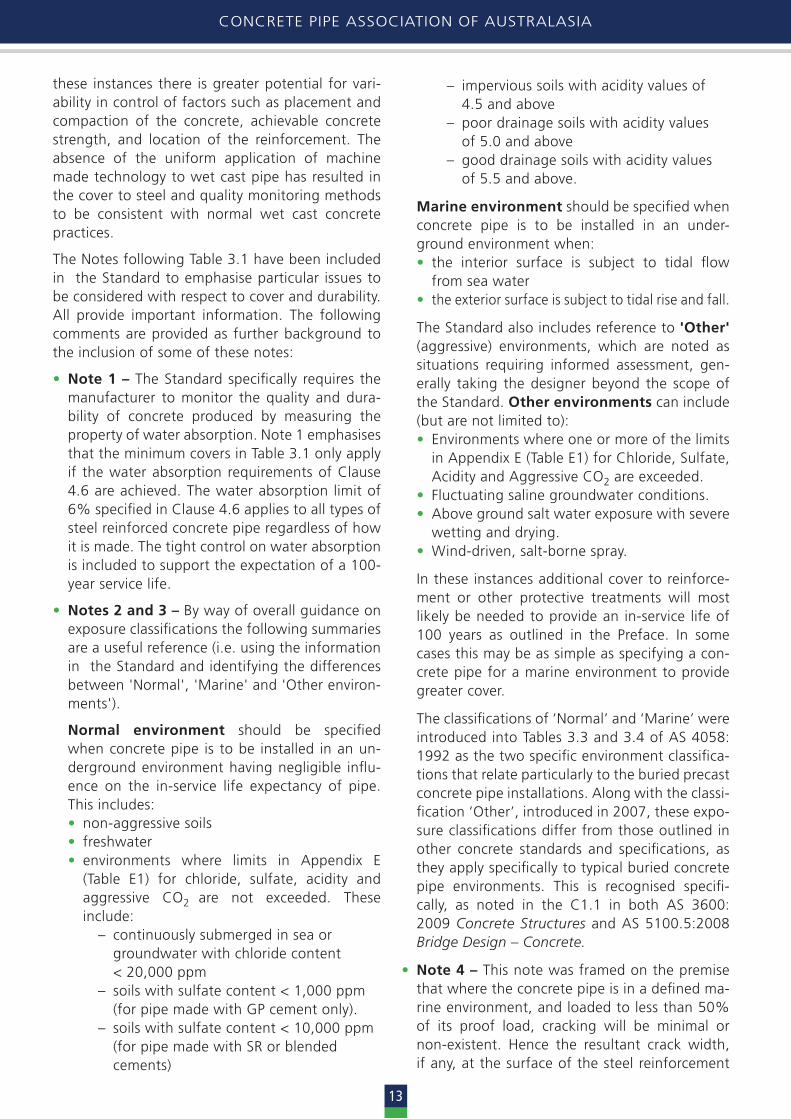
For the purposes of explanation, Table 3.1 (and its Notes) from the Standard has been reproduced below.
NOTES: 1. The minimum cover specifications apply to pipes with water absorption no greater than the values given in Clause 4.6.2. Appendix E gives information on concentration limits applicable to some constituents of the buried environment when using concrete with water absorption in accordance with Clause 4.6.3. ‘Other environment’ refers to environments that do not comply with the definitions for either Normal or Marine environments. These include environments in which one or more of the limits in Appendix E is exceeded (e.g. above ground salt water exposure
with severe wetting and drying). Specification of cover or other protective treatment for these situations requires an informed assessment drawing on information not available in this Standard.4. Where pipes are loaded to less than 50% of the proof load for a Marine environment, barrel cover for pipes with water water absorption in accordance with Clause 4.6 may be reduced to 15 mm for machine made and 20 mm for wet cast.5. Maximum 10 mm reinforcing bar or wire for nominated concrete covers to reinforcement.6. N/A = Not applicable. Pipe wall geometry does not permit a pipe wall ≤ 35 mm to be specified for a marine environment.
Minimum cover – Minimum cover – barrel & socket (mm) mating surface of spigot (mm)
Method of manufacture Environment
Normal Marine Other Normal Marine Other
Machine made pipe (Wall thickness) ≤ 25 6 N/A 4 N/A > 25, ≤ 35 8 N/A See Note 3 5 N/A See Note 3 > 35 10 20 6 10 Wet cast pipe (50 MPa) 25 35 25 35
13
CONCRETE PIPE ASSOCIATION OF AUSTRALASIA
these instances there is greater potential for vari-ability in control of factors such as placement and compaction of the concrete, achievable concrete strength, and location of the reinforcement. The absence of the uniform application of machine made technology to wet cast pipe has resulted in the cover to steel and quality monitoring methods to be consistent with normal wet cast concrete practices.
The Notes following Table 3.1 have been included in the Standard to emphasise particular issues to be considered with respect to cover and durability. All provide important information. The following comments are provided as further background to the inclusion of some of these notes:
• Note 1 – The Standard specifically requires the manufacturer to monitor the quality and dura-bility of concrete produced by measuring the property of water absorption. Note 1 emphasises that the minimum covers in Table 3.1 only apply if the water absorption requirements of Clause 4.6 are achieved. The water absorption limit of 6% specified in Clause 4.6 applies to all types of steel reinforced concrete pipe regardless of how it is made. The tight control on water absorption is included to support the expectation of a 100- year service life.
• Notes 2 and 3 – By way of overall guidance on exposure classifications the following summaries are a useful reference (i.e. using the information in the Standard and identifying the differences between 'Normal', 'Marine' and 'Other environ-ments').
Normal environment should be specified when concrete pipe is to be installed in an un-derground environment having negligible influ-ence on the in-service life expectancy of pipe. This includes:• non-aggressive soils• freshwater• environments where limits in Appendix E
(Table E1) for chloride, sulfate, acidity and aggressive CO2 are not exceeded. These include: – continuously submerged in sea or groundwater with chloride content < 20,000 ppm – soils with sulfate content < 1,000 ppm (for pipe made with GP cement only). – soils with sulfate content < 10,000 ppm (for pipe made with SR or blended cements)
– impervious soils with acidity values of 4.5 and above – poor drainage soils with acidity values of 5.0 and above – good drainage soils with acidity values of 5.5 and above.
Marine environment should be specified when concrete pipe is to be installed in an under-ground environment when:• the interior surface is subject to tidal flow
from sea water• the exterior surface is subject to tidal rise and fall.
The Standard also includes reference to 'Other' (aggressive) environments, which are noted as situations requiring informed assessment, gen-erally taking the designer beyond the scope of the Standard. Other environments can include (but are not limited to):• Environments where one or more of the limits
in Appendix E (Table E1) for Chloride, Sulfate, Acidity and Aggressive CO2 are exceeded.
• Fluctuating saline groundwater conditions.• Above ground salt water exposure with severe
wetting and drying.• Wind-driven, salt-borne spray.
In these instances additional cover to reinforce-ment or other protective treatments will most likely be needed to provide an in-service life of 100 years as outlined in the Preface. In some cases this may be as simple as specifying a con-crete pipe for a marine environment to provide greater cover.
The classifications of ‘Normal’ and ‘Marine’ were introduced into Tables 3.3 and 3.4 of AS 4058: 1992 as the two specific environment classifica-tions that relate particularly to the buried precast concrete pipe installations. Along with the classi-fication ‘Other’, introduced in 2007, these expo-sure classifications differ from those outlined in other concrete standards and specifications, as they apply specifically to typical buried concrete pipe environments. This is recognised specifi- cally, as noted in the C1.1 in both AS 3600: 2009 Concrete Structures and AS 5100.5:2008 Bridge Design – Concrete.
• Note 4 – This note was framed on the premise that where the concrete pipe is in a defined ma-rine environment, and loaded to less than 50% of its proof load, cracking will be minimal or non-existent. Hence the resultant crack width, if any, at the surface of the steel reinforcement

CONCRETE PIPE ASSOCIATION OF AUSTRALASIA
14
GUIDE TO UNDERSTANDING AS/NZS 4058:2007
will be so diminished that it will not allow the continuous passage of moisture and creation of an unstable environment. As a result, a lesser cover to steel is permissible.
However since the publishing of the Standard in 2007 it has been noted that Note 4 of Table 3.1 nominates a 20 mm cover for wet cast pipe for marine environments. This value is less than the 25 mm specified for wet cast pipe for normal environment. To address this anomaly it is suggested that 'where pipes are loaded to less than 50% of the proof load for a marine environment, barrel cover for pipes with water absorption in accordance with Clause 4.6, may be reduced to 15 mm for machine made and 30 mm for wet cast.
Further to this it is important to note that in practice the limiting and monitoring of the actual loads on an installed pipe may be difficult to control (i.e. the nominated cover reductions should only be considered where all loads on the pipe are known and accurately assessed and the pipe installation is strictly controlled).
• Note 5 – This note was included to advise against the use of reinforcement in excess of 10 mm diameter when the minimum covers of 10 mm or less are adopted. Where the use of wire diame-ters greater than 10 mm is necessary for pipes of large size class and/or load class, the pipe design shall be an engineered solution where the cov-er adopted is appropriate to the reinforcement diameter required. As a rule, cover should be typically 1 to 1.5 times the reinforcement diameter.
• Note 5 – This note, whilst largely self-expla- natory, was included to emphasise that when designing concrete pipes for marine environ-ments, the minimum design thicknesses required for the barrel, socket and spigot will be at least the sum of 2 times the specified cover, plus the combined thickness of the assembled reinforce-ment cage.
C3.2 Workmanship and FinishC3.4.2.2 Defect types
The overriding requirements for satisfactory perfor-mance of steel reinforced concrete pipe are:
a) the provision of a sound pipe wall section
b) the maintenance of a suitable chemically passive environment at the steel reinforcement interface.
The defect types identified in Clause 3.4.2.2 of the Standard have been classified by their physical ap-pearance and rated by their potential to impact on the structural soundness and durability of the product. These include cracking, dents, bulges, chips, spalls and inclusion of foreign matter.
• Cracking – It is important to note that from the outset in this section, Clause 3.4.2.1 of the Standard nominates that surface craze cracks and hairline cracks not extending through the wall are not to be classified as defects. These types of cracks have no impact on the structural cross section of the pipe wall or its durability.
Following this, Clause 3.4.2.2 of the Standard nominates seven types of defects in concrete pipe that should be inspected for. Defect Types 1, 2 and 3 classify concrete cracking on the basis of crack width and the extent of the cracking through the pipe wall. It has been established that the maximum acceptable crack widths and covers nominated in Table 3.5 of the Standard are acceptable under Type 1 defects, for pipes installed in a 'normal’ environment. In other words, for the tabulated combinations of outer surface crack width and cover to the reinforce-ment, the resultant crack width at the surface of the steel reinforcement is insufficient to allow the continuous passage of moisture and creation of an unstable environment.
A conservative maximum crack width of 0.10 mm for a Type 1 defect, regardless of cover, has been adopted for sewer pipe and marine envi-ronments because of the uncertainty as to the precise nature applicable to this broad range of more aggressive environments. Cracks in excess of the appropriate maximum acceptable crack width specified in Table 3.5 are further classified by comparing the measured crack width with the values in Table C2 in Appendix C.
For example:− A defect Type 2 classification applies where
the measured load test crack width does not exceed the appropriate maximum value speci-fied in Table C2.
− A defect Type 3 classification applies to crack widths greater than the maximums in Table C2 but is still less than or equal to 0.5 mm.
− A defect Type 3 classification also applies to cracks that extend through the pipe wall.
15
CONCRETE PIPE ASSOCIATION OF AUSTRALASIA
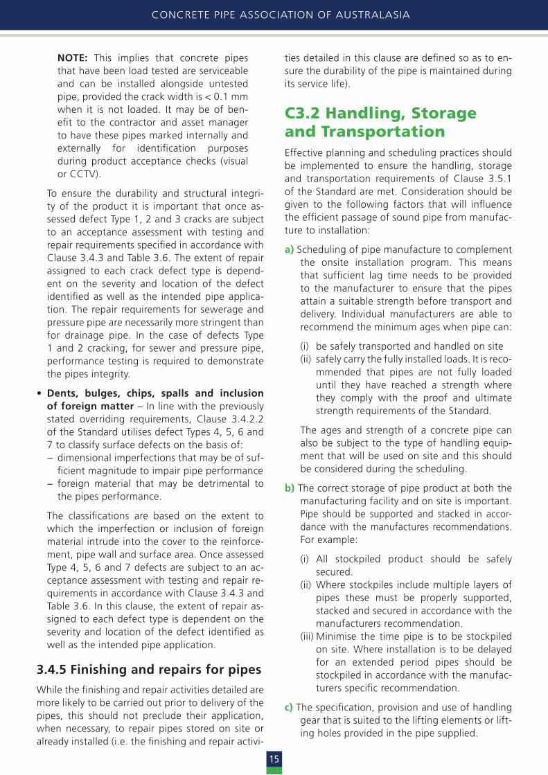
NOTE: This implies that concrete pipes that have been load tested are serviceable and can be installed alongside untested pipe, provided the crack width is < 0.1 mm when it is not loaded. It may be of ben-efit to the contractor and asset manager to have these pipes marked internally and externally for identification purposes during product acceptance checks (visual or CCTV).
To ensure the durability and structural integri-ty of the product it is important that once as-sessed defect Type 1, 2 and 3 cracks are subject to an acceptance assessment with testing and repair requirements specified in accordance with Clause 3.4.3 and Table 3.6. The extent of repair assigned to each crack defect type is depend-ent on the severity and location of the defect identified as well as the intended pipe applica-tion. The repair requirements for sewerage and pressure pipe are necessarily more stringent than for drainage pipe. In the case of defects Type 1 and 2 cracking, for sewer and pressure pipe, performance testing is required to demonstrate the pipes integrity.
• Dents, bulges, chips, spalls and inclusion of foreign matter – In line with the previously stated overriding requirements, Clause 3.4.2.2 of the Standard utilises defect Types 4, 5, 6 and 7 to classify surface defects on the basis of:− dimensional imperfections that may be of suf-
ficient magnitude to impair pipe performance− foreign material that may be detrimental to
the pipes performance.
The classifications are based on the extent to which the imperfection or inclusion of foreign material intrude into the cover to the reinforce-ment, pipe wall and surface area. Once assessed Type 4, 5, 6 and 7 defects are subject to an ac-ceptance assessment with testing and repair re-quirements in accordance with Clause 3.4.3 and Table 3.6. In this clause, the extent of repair as-signed to each defect type is dependent on the severity and location of the defect identified as well as the intended pipe application.
3.4.5 Finishing and repairs for pipes
While the finishing and repair activities detailed are more likely to be carried out prior to delivery of the pipes, this should not preclude their application, when necessary, to repair pipes stored on site or already installed (i.e. the finishing and repair activi-
ties detailed in this clause are defined so as to en-sure the durability of the pipe is maintained during its service life).
C3.2 Handling, Storage and TransportationEffective planning and scheduling practices should be implemented to ensure the handling, storage and transportation requirements of Clause 3.5.1 of the Standard are met. Consideration should be given to the following factors that will influence the efficient passage of sound pipe from manufac-ture to installation:
a) Scheduling of pipe manufacture to complement the onsite installation program. This means that sufficient lag time needs to be provided to the manufacturer to ensure that the pipes attain a suitable strength before transport and delivery. Individual manufacturers are able to recommend the minimum ages when pipe can:
(i) be safely transported and handled on site(ii) safely carry the fully installed loads. It is reco-
mmended that pipes are not fully loaded until they have reached a strength where they comply with the proof and ultimate strength requirements of the Standard.
The ages and strength of a concrete pipe can also be subject to the type of handling equip-ment that will be used on site and this should be considered during the scheduling.
b) The correct storage of pipe product at both the manufacturing facility and on site is important. Pipe should be supported and stacked in accor- dance with the manufactures recommendations. For example:
(i) All stockpiled product should be safely secured.
(ii) Where stockpiles include multiple layers of pipes these must be properly supported, stacked and secured in accordance with the manufacturers recommendation.
(iii) Minimise the time pipe is to be stockpiled on site. Where installation is to be delayed for an extended period pipes should be stockpiled in accordance with the manufac-turers specific recommendation.
c) The specification, provision and use of handling gear that is suited to the lifting elements or lift-ing holes provided in the pipe supplied.
GUIDE TO UNDERSTANDING AS/NZS 4058:2007
16
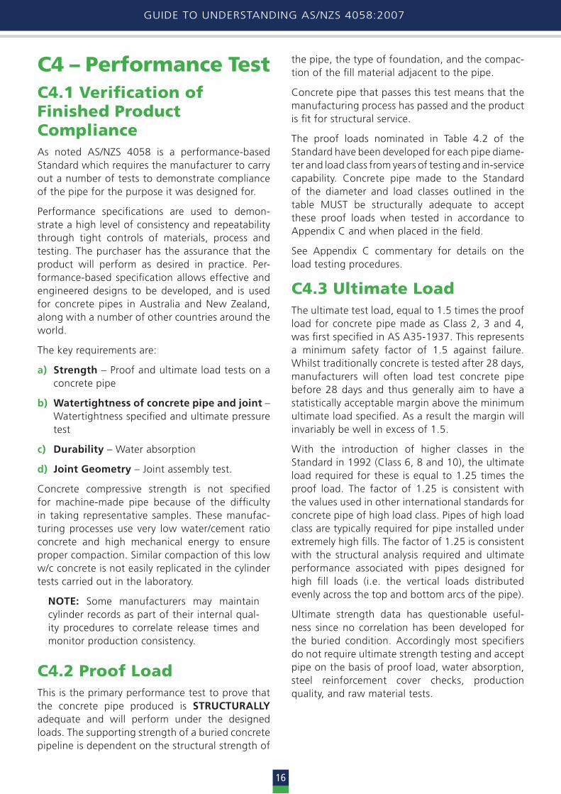
C4 – Performance TestC4.1 Verification of Finished Product Compliance As noted AS/NZS 4058 is a performance-based Standard which requires the manufacturer to carry out a number of tests to demonstrate compliance of the pipe for the purpose it was designed for.
Performance specifications are used to demon-strate a high level of consistency and repeatability through tight controls of materials, process and testing. The purchaser has the assurance that the product will perform as desired in practice. Per-formance-based specification allows effective and engineered designs to be developed, and is used for concrete pipes in Australia and New Zealand, along with a number of other countries around the world.
The key requirements are:
a) Strength – Proof and ultimate load tests on a concrete pipe
b) Watertightness of concrete pipe and joint – Watertightness specified and ultimate pressure test
c) Durability – Water absorption
d) Joint Geometry – Joint assembly test.
Concrete compressive strength is not specified for machine-made pipe because of the difficulty in taking representative samples. These manufac-turing processes use very low water/cement ratio concrete and high mechanical energy to ensure proper compaction. Similar compaction of this low w/c concrete is not easily replicated in the cylinder tests carried out in the laboratory.
NOTE: Some manufacturers may maintain cylinder records as part of their internal qual-ity procedures to correlate release times and monitor production consistency.
C4.2 Proof LoadThis is the primary performance test to prove that the concrete pipe produced is STRUCTURALLY adequate and will perform under the designed loads. The supporting strength of a buried concrete pipeline is dependent on the structural strength of
the pipe, the type of foundation, and the compac-tion of the fill material adjacent to the pipe.
Concrete pipe that passes this test means that the manufacturing process has passed and the product is fit for structural service.
The proof loads nominated in Table 4.2 of the Standard have been developed for each pipe diame-ter and load class from years of testing and in-service capability. Concrete pipe made to the Standard of the diameter and load classes outlined in the table MUST be structurally adequate to accept these proof loads when tested in accordance to Appendix C and when placed in the field.
See Appendix C commentary for details on the load testing procedures.
C4.3 Ultimate LoadThe ultimate test load, equal to 1.5 times the proof load for concrete pipe made as Class 2, 3 and 4, was first specified in AS A35-1937. This represents a minimum safety factor of 1.5 against failure. Whilst traditionally concrete is tested after 28 days, manufacturers will often load test concrete pipe before 28 days and thus generally aim to have a statistically acceptable margin above the minimum ultimate load specified. As a result the margin will invariably be well in excess of 1.5.
With the introduction of higher classes in the Standard in 1992 (Class 6, 8 and 10), the ultimate load required for these is equal to 1.25 times the proof load. The factor of 1.25 is consistent with the values used in other international standards for concrete pipe of high load class. Pipes of high load class are typically required for pipe installed under extremely high fills. The factor of 1.25 is consistent with the structural analysis required and ultimate performance associated with pipes designed for high fill loads (i.e. the vertical loads distributed evenly across the top and bottom arcs of the pipe).
Ultimate strength data has questionable useful-ness since no correlation has been developed for the buried condition. Accordingly most specifiers do not require ultimate strength testing and accept pipe on the basis of proof load, water absorption, steel reinforcement cover checks, production quality, and raw material tests.
HYDRAULICS OF PRECAST CONCRETE CONDUITS
17
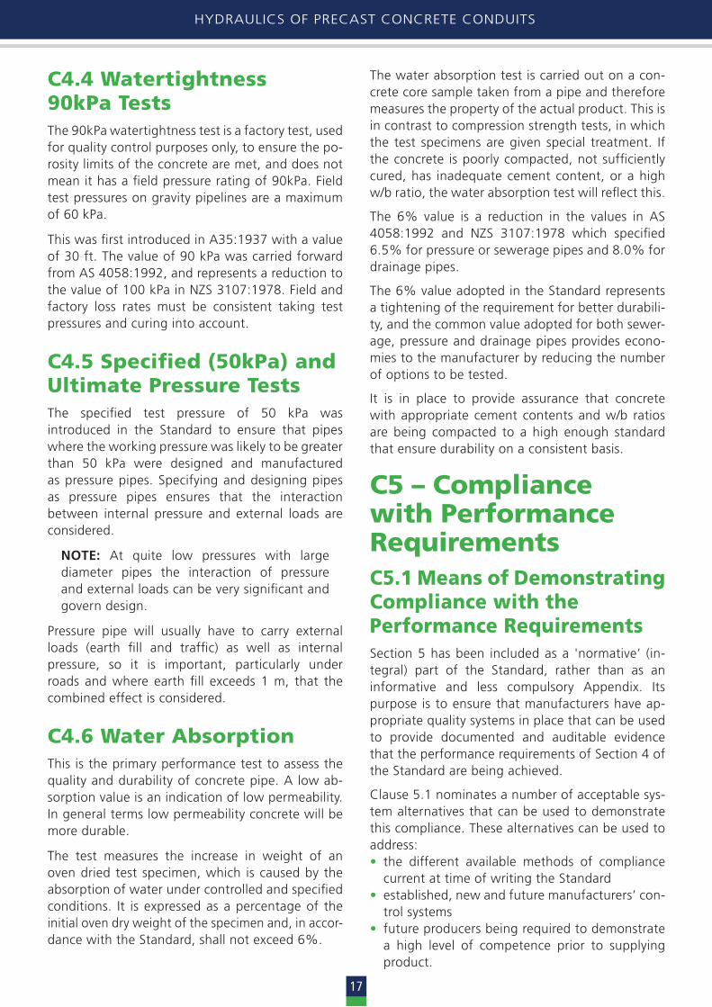
C4.4 Watertightness90kPa TestsThe 90kPa watertightness test is a factory test, used for quality control purposes only, to ensure the po-rosity limits of the concrete are met, and does not mean it has a field pressure rating of 90kPa. Field test pressures on gravity pipelines are a maximum of 60 kPa.
This was first introduced in A35:1937 with a value of 30 ft. The value of 90 kPa was carried forward from AS 4058:1992, and represents a reduction to the value of 100 kPa in NZS 3107:1978. Field and factory loss rates must be consistent taking test pressures and curing into account.
C4.5 Specified (50kPa) andUltimate Pressure TestsThe specified test pressure of 50 kPa was introduced in the Standard to ensure that pipes where the working pressure was likely to be greater than 50 kPa were designed and manufactured as pressure pipes. Specifying and designing pipes as pressure pipes ensures that the interaction between internal pressure and external loads are considered.
NOTE: At quite low pressures with large diameter pipes the interaction of pressure and external loads can be very significant and govern design.
Pressure pipe will usually have to carry external loads (earth fill and traffic) as well as internal pressure, so it is important, particularly under roads and where earth fill exceeds 1 m, that the combined effect is considered.
C4.6 Water AbsorptionThis is the primary performance test to assess the quality and durability of concrete pipe. A low ab-sorption value is an indication of low permeability. In general terms low permeability concrete will be more durable.
The test measures the increase in weight of an oven dried test specimen, which is caused by the absorption of water under controlled and specified conditions. It is expressed as a percentage of the initial oven dry weight of the specimen and, in accor- dance with the Standard, shall not exceed 6%.
The water absorption test is carried out on a con-crete core sample taken from a pipe and therefore measures the property of the actual product. This is in contrast to compression strength tests, in which the test specimens are given special treatment. If the concrete is poorly compacted, not sufficiently cured, has inadequate cement content, or a high w/b ratio, the water absorption test will reflect this.
The 6% value is a reduction in the values in AS 4058:1992 and NZS 3107:1978 which specified 6.5% for pressure or sewerage pipes and 8.0% for drainage pipes.
The 6% value adopted in the Standard represents a tightening of the requirement for better durabili-ty, and the common value adopted for both sewer-age, pressure and drainage pipes provides econo-mies to the manufacturer by reducing the number of options to be tested.
It is in place to provide assurance that concrete with appropriate cement contents and w/b ratios are being compacted to a high enough standard that ensure durability on a consistent basis.
C5 – Compliance with PerformanceRequirementsC5.1 Means of Demonstrating Compliance with thePerformance RequirementsSection 5 has been included as a 'normative’ (in-tegral) part of the Standard, rather than as an informative and less compulsory Appendix. Its purpose is to ensure that manufacturers have ap-propriate quality systems in place that can be used to provide documented and auditable evidence that the performance requirements of Section 4 of the Standard are being achieved.
Clause 5.1 nominates a number of acceptable sys-tem alternatives that can be used to demonstrate this compliance. These alternatives can be used to address:• the different available methods of compliance
current at time of writing the Standard• established, new and future manufacturers’ con-
trol systems• future producers being required to demonstrate
a high level of competence prior to supplying product.

GUIDE TO UNDERSTANDING AS/NZS 4058:2007
18
An auditable system based on AS/NZS ISO 9001 Quality management systems – Requirements provides an effective means of implementing a sampling and testing program in accordance with Clause 5.2. It is important to note that in addition to the requirements of Section 5, Sections 2 and 3 of the Standard require that the manufacturers can demonstrate adequate systems of process control.
Specifically the Standard requires pipe manufactur-ers to have an auditable system that monitors and demonstrates compliance of:
• all raw materials (refer to Section 2.1)• the manufacturing processes (refer to Section
3.1)• compliance to the performance requirements
of Section 4, including the finished product. (refer to 5.1).
NOTE: Pipe manufacturers who are members of the Concrete Pipe Association of Australasia are required to have an audited quality management system in accordance ISO 9001 to ensure the concrete pipe they make meets the requirements of the Standard.
C5.2 Sampling and Testing
C5.2.3 Test requirements
The tests described in Table 5.1 of the Standard fall into two distinct categories. These are:
a) Type testing – This testing regime applies where verification of a newly commissioned manufacturing facility, new design or a signif-icant departure from a proven design is pro-posed. Refer to Clause 5.2.2 (a) in the Standard for examples of 'significant changes'.
Clause 5.2.4 and Table 5.2 of the Standard
details the specific tests and sampling require-ments for conducting type testing. Table 5.1 specifies that type testing is 'required' for all the characteristics listed in the table. The num-bers of specimens to be tested for each of the characteristics is nominated in Table 5.2. All characteristics must be tested to effectively verify a new facility or new design.
Established pipe manufacturers have sets of proven pipe designs prepared using their own empirical pipe design rules/formulae. Typically these empirical design formulae have been de-veloped from the accumulated type testing re-cords and routine testing records available at the time for analysis of performance.
Subsequent routine testing has further con-firmed the validity of these design formulae. The requirement for new type testing does not apply where a manufacturer’s existing proven pipe design formulae are used as the basis for an individual pipe design or set of designs
b) Routine Testing – Once it is established that the new facility, new or altered design complies with the specified quality parameters, type test-ing ceases and routine testing commences, i.e. refer to Clause 5.2.2 (b) in the Standard. Rou-tine testing is the process of monitoring normal pipe production on an ongoing basis. Clause 5.2.5 and Appendix A of the Standard details the specific tests and sampling requirements for this testing. For each characteristic Table 5.1 nominates where routine testing is 'required' or will be carried out 'only if specified' in accord-ance with Section 6 'Ordering and Supplying Pipes' of the Standard i.e. the 'required' option has been nominated where:
(i) the characteristic can vary for an individual production run, e.g. cover to reinforcement
(ii) the characteristic is used to demonstrate that the finished pipe not only meets a specified performance Standard but indi-cates the overall manufacturing processes are under control, i.e. as they were when type testing verified, e.g. proof load testing, water absorption testing
(iii) further to (i) and (ii) the combination of results from 'required' monitoring of two or more these characteristics provide a confidence in the achievement of anoth-er specified characteristic, e.g. successful proof load testing in combination with con-firmation of correct cover to reinforcement are used as confirmation that the specified ultimate load capacity is unchanged.
Hence characteristics such as 'ultimate load' testing which entail the considerable additional cost of destructive testing are in a majority of cases not required to be routinely checked, e.g. in Table 5.1 these characteristics are assigned the option 'only if specified'.
The 'only if specified' option has been nomi-nated where:
(i) the characteristic is not likely to change once type testing has proved the capability of the design for that characteristic, e.g. dimensional accuracy of a pipe mould that has been established by type testing

HYDRAULICS OF PRECAST CONCRETE CONDUITS
19
(ii) the specifier/purchaser has a particular reason to request a test that for most other applications is not necessary, e.g. water-tightness (90 kPa) for drainage pipe instal-lation
(iii) further to (i) the expense of the particular and possibly destructive test is unneces-sary once the type testing has verified the pipe has that design capability, e.g. ultimate load, ultimate pressure.
Appendices
CA Sampling Scheme for Routine TestingThis Appendix outlines the sampling schemes re-quired to ensure that manufacturers are meeting the performance requirements for concrete pipe in accordance with the Standard on a consistent basis. As such it provides manufacturers with the rules they must follow when selecting a sample of pipe to routinely test for performance.
The Appendix provides three inspection modes for sampling. What mode is implemented is depend-ent on the historical performance of the manufac-turer and their ability to control their production methods to provide consistent well performed pipe. Manufacturers can change from one inspec-tion mode to another in accordance with switching rules nominated in the Standard which are based on the demonstrated control of their processes.
Typical sampling plans are outlined in the Appendix for the mandatory routine tests (proof load, water absorption and cover to reinforcement), as well as those that can be specified upon request by the specifiers.
CB Checklist of PurchasingRequirementsThe Appendix provides purchasers with a checklist to ensure that the concrete pipe required for any particular project is supplied. The flow chart below is designed to help specifiers and purchasers to use the checklist to ensure that all aspects of the pipe are considered before it is signed off.
As a guide, the following three examples are pro-vided to show how the checklist can be used for concrete pipe used for stormwater drainage in a normal environment and a marine environment, as well as pipe specified for a pressure application. Use the flow chart to see if you arrive at the same requirements.

GUIDE TO UNDERSTANDING AS/NZS 4058:2007
20
CPAA Draft – Guide to Understanding AS/NZS 4058
21
Diagram: Flow chart of checklist requirements in Appendix B
1. Pipe details & application Nominate size class/nominal diameter (from Table 4.2 of AS/NZS 4058)
Agree on the nominal length of the pipe (with manufacturer)
Nominate joint type - RIGID (i.e. flush jointed) - FLEXIBLE (i.e. rolling rubber ring, skid ring) - OTHER (details must be nominated and agreed upon)
Designer specified load class of pipe nominated (selected from Table 4.2 of AS/NZS 4058)
Pipe application/use nominated
Drainage Pressure Sewer
2. Pressure requirements
Nominate if field acceptance test required?
NO YES – nominate the test pressure required (kPa)
Nominate if 90 kPa watertightness test required?
Nominate the allowable working pressure (kPa) ensuring the value specified includes an evaluation of: 1. The dynamic or surge effects 2. The installation conditions*
Nominate the factory test pressure to be applied (kPa)
3. Special requirements Any special requirements outside the minimum specified in AS/NZS 4058
NO YES – provide detail only when a requirement differs for pipe not manufactured for NORMAL environment
4. Quantities & delivery advice
Durability - Marine environment - Minimum cover - Cement type - SCM content - Admixtures - Linings/coatings
Testing - Tests required outside
of specified routine tests.
Finishing/Repair - Materials needed
Jacking Markings
Specify quantity of pipe, delivery address and delivery program
NO YES
* Refer to AS/NZS 3725 and AS/NZS 4058 to confirm the nominated tests are appropriate to the installation conditions and pipeline application.
NOTE: Section 2 is only applicable where a pipeline is to operate at a specified working pressure or is to be field tested for acceptance or where watertightness is specified
Diagram:Flow chart of checklist requirements in Appendix B

HYDRAULICS OF PRECAST CONCRETE CONDUITS
21
Example A – Normal EnvironmentA designer has specified 1.5 km of size 450 mm diameter, Class 2 drainage pipe (flush jointed) for a single trench application in an open paddock. The excavation is entirely in material that is classified as wet clay fill, and no construction machinery or other vehicle will pass over the pipe. The depth of the trench to the pipe invert is 2.25 m, and the soil and groundwater does not contain any aggressive materials.
Use the Checklist of Purchasing Requirements, outlined in AS/NZS 4058 Appendix B.
CPAA Draft – Guide to Understanding AS/NZS 4058
22
Example A – normal environment A designer has specified 1.5 km of size 450mm diameter, Class 2 drainage pipe (flush jointed) for a single trench application in an open paddock. The excavation is entirely in material that is classified as wet clay fill, and no construction machinery or other vehicle will pass over the pipe. The depth of the trench to the pipe invert is 2.25m, and the soil and groundwater does not contain any aggressive materials. Using the Checklist of Purchasing Requirements, outlined in AS/NZS 4058 Appendix B - Section 1. Pipe details and application: 1a Pipe details ‒ Size class or nominal diameter DN: 450mm ‒ Pipe length: 2.44 m ‒ Type of joint: Rigid or
Flexible with elastomeric seal: natural rubber other (details attached)
‒ Load class: 2 1b Application or Use: ‒ Drainage Proceed to Section 3 NOTE: If a watertightness test is specified, complete Sections 2a and 2b.
‒ Sewer Proceed to Sections 2a and 2b.
‒ Pressure Proceed to Section 2c.
Section 2. Pressure requirements: NOTE: Section 2 only applicable where a pipeline is to operate at a specified working pressure or is to be field-tested for acceptance, or where watertightness
is specified.
2a Field acceptance tests: ‒ Is the installed line to be subjected to a field acceptance test: (See Note) NO YES kPa 2b ‒ Watertightness requirements for non-pressure pipe: ‒ Has the watertightness test (90 kPa) been specified? (see Note) NO YES
PROCEED TO SECTION 3 2c Pressure pipe requirements: ‒ Is allowable working pressure (including dynamic or surge effects) specified? NO YES kPa
‒ When establishing the working pressure has the specifier evaluated the installation conditions? NO YES See Note
‒ Is a factory test pressure specified NO YES kPa NOTE: Refer purchaser/specifier to AS/NZS 3725 and AS/NZS 4058 to confirm the nominated tests
are appropriate to the installation conditions and pipeline application.
PROCEED TO SECTION 3 Section 3. Special requirements:
‒ Any special requirements : NO ‒ Proceed to Section 4
YES ‒ Provide detail only when a requirement differs from normal manufacturing practice
‒ Jacking pipe YES ‒ Marine conditions: YES ‒ Minimum cover:
‒ Cement type ‒ Admixtures:
‒ Finishing and repair materials ‒ Lining/surface treatments: ‒ Markings:
‒ Other: Refer to Section 6 of AS/NZS 4058
‒ Additional tests (i.e. other than AS/NZS 4058 requirements):
PROCEED TO SECTION 4 Section 4. Quantities and delivery advice:
‒ Quantities specified? NO YES ‒ Delivery address specified? NO YES ‒ Delivery program specified? NO YES
X
X
X
X
X
X
GUIDE TO UNDERSTANDING AS/NZS 4058:2007
22
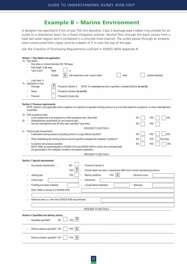
Example B – Marine Environment A designer has specified 0.5 km of size 750 mm diameter, Class 3 drainage pipe (rubber ring jointed) for an outlet to a retardation basin for a flood mitigation scheme. Normal flow through the basin comes from a tidal salt water lagoon and is contained in a concrete lined channel. The outlet passes through an embank-ment constructed from clayey sand to a depth of 5 m over the top of the pipe.
Use the Checklist of Purchasing Requirements outlined in AS/NZS 4058 Appendix B.
CPAA Draft – Guide to Understanding AS/NZS 4058
23
Example B – marine environment A designer has specified 0.5 km of size 750mm diameter, Class 3 drainage pipe (rubber ring jointed) for an outlet to a retardation basin for a flood mitigation scheme. Normal flow through the basin comes from a tidal salt water lagoon and is contained in a concrete lined channel. The outlet passes through an embankment constructed from clayey sand to a depth of 5 metres over the top of the pipe… Using the Checklist of Purchasing Requirements, outlined in AS/NZS 4058 Appendix B - Section 1. Pipe details and application: 1a Pipe details ‒ Size class or nominal diameter DN: 750 mm ‒ Pipe length: 2.44 mm ‒ Type of joint: Rigid or
Flexible with elastomeric seal: natural rubber other (details attached)
‒ Load class: 3 1b Application or Use: ‒ Drainage Proceed to Section 3 NOTE: If a watertightness test is specified, complete Sections 2a and 2b.
‒ Sewer Proceed to Sections 2a and 2b.
‒ Pressure Proceed to Section 2c.
Section 2. Pressure requirements: NOTE: Section 2 only applicable where a pipeline is to operate at a specified working pressure or is to be field-tested for acceptance, or where watertightness
is specified.
2a Field acceptance tests: ‒ Is the installed line to be subjected to a field acceptance test: (See Note) NO YES kPa 2b ‒ Watertightness requirements for non-pressure pipe: ‒ Has the watertightness test (90 kPa) been specified? (see Note) NO YES
PROCEED TO SECTION 3 2c Pressure pipe requirements: ‒ Is allowable working pressure (including dynamic or surge effects) specified? NO YES kPa
‒ When establishing the working pressure has the specifier evaluated the installation conditions? NO YES See Note
‒ Is a factory test pressure specified NO YES kPa NOTE: Refer purchaser/specifier to AS/NZS 3725 and AS/NZS 4058 to confirm the nominated tests
are appropriate to the installation conditions and pipeline application.
PROCEED TO SECTION 3 Section 3. Special requirements:
‒ Any special requirements : NO ‒ Proceed to Section 4
YES ‒ Provide detail only when a requirement differs from normal manufacturing practice
‒ Jacking pipe YES ‒ Marine conditions: YES ‒ Minimum cover:
‒ Cement type ‒ Admixtures:
‒ Finishing and repair materials ‒ Lining/surface treatments: ‒ Markings:
‒ Other: Refer to Section 6 of AS/NZS 4058
‒ Additional tests (i.e. other than AS/NZS 4058 requirements):
PROCEED TO SECTION 4 Section 4. Quantities and delivery advice:
‒ Quantities specified? NO YES ‒ Delivery address specified? NO YES ‒ Delivery program specified? NO YES
X
X
X X
X
X
X

HYDRAULICS OF PRECAST CONCRETE CONDUITS
23
Example C – Pressure PipeA designer has specified 800 metres of size 750 mm diameter, Class 4 pressure pipe for a concrete irrigation line that will pass through a sandy clay roadway embankment. The road is a dual lane highway designed for typical vehicle loads and where it crosses the pipeline its surface is 2.5 m above the pipe invert. The pipe is expected to withstand a shut-down head of 40 m plus a 25% allowance for water hammer.
Use the Checklist of Purchasing Requirements outlined in AS/NZS 4058 Appendix B.
CPAA Draft – Guide to Understanding AS/NZS 4058
24
Example C – pressure pipe A designer has specified 800 metres of size 750 mm diameter, Class 4 pressure pipe for a concrete irrigation line that will pass through a sandy clay roadway embankment. The road is a dual lane highway designed for typical vehicle loads and where it crosses the pipeline its surface is 2.5 m above the pipe invert. The pipe is expected to withstand a shut-down head of 40.0m plus a 25% allowance for water hammer. Using the Checklist of Purchasing Requirements, outlined in AS/NZS 4058 Appendix B - Section 1. Pipe details and application: 1a Pipe details ‒ Size class or nominal diameter DN: 750 mm ‒ Pipe length: 2.4 m ‒ Type of joint: Rigid or
Flexible with elastomeric seal: natural rubber other (details attached)
‒ Load class: 4 1b Application or Use: ‒ Drainage Proceed to Section 3 NOTE: If a watertightness test is specified, complete Sections 2a and 2b.
‒ Sewer Proceed to Sections 2a and 2b.
‒ Pressure Proceed to Section 2c.
Section 2. Pressure requirements: NOTE: Section 2 only applicable where a pipeline is to operate at a specified working pressure or is to be field-tested for acceptance, or where watertightness
is specified.
2a Field acceptance tests: ‒ Is the installed line to be subjected to a field acceptance test: (See Note) NO YES kPa 2b ‒ Watertightness requirements for non-pressure pipe: ‒ Has the watertightness test (90 kPa) been specified? (see Note) NO YES
PROCEED TO SECTION 3 2c Pressure pipe requirements: ‒ Is allowable working pressure (including dynamic or surge effects) specified? NO YES kPa
‒ When establishing the working pressure has the specifier evaluated the installation conditions? NO YES See Note
‒ Is a factory test pressure specified NO YES kPa NOTE: Refer purchaser/specifier to AS/NZS 3725 and AS/NZS 4058 to confirm the nominated tests
are appropriate to the installation conditions and pipeline application.
PROCEED TO SECTION 3 Section 3. Special requirements:
‒ Any special requirements : NO ‒ Proceed to Section 4
YES ‒ Provide detail only when a requirement differs from normal manufacturing practice
‒ Jacking pipe YES ‒ Marine conditions: YES ‒ Minimum cover:
‒ Cement type ‒ Admixtures:
‒ Finishing and repair materials ‒ Lining/surface treatments: ‒ Markings:
‒ Other: Refer to Section 6 of AS/NZS 4058
‒ Additional tests (i.e. other than AS/NZS 4058 requirements):
PROCEED TO SECTION 4 Section 4. Quantities and delivery advice:
‒ Quantities specified? NO YES ‒ Delivery address specified? NO YES ‒ Delivery program specified? NO YES
X
X
X 490
X X
X
X
X
X

GUIDE TO UNDERSTANDING AS/NZS 4058:2007
24
CC Load Tests for Concrete PipesLoad testing is vital for determining the load-carrying capacity of concrete pipe for which it has been de-signed. The primary performance test to prove that the concrete pipe produced is structurally adequate and will perform under the designed loads is known as the proof load test, whilst an ultimate load-carry-ing capacity can also be tested for.
This type of load testing is commonly conducted throughout the world and can be performed using the three-edge or two-edge bearing test. In both cases a machine is used which is designed to apply a force in a true vertical plane, parallel to the vertical centreline, and extending the full length of the speci-men. Using the three-edge bearing method the test specimen is supported on two parallel longitudinal strips and the load (force) applied through a top bearing beam. The two-edge bearing method uses the same methodology but the test specimen is sup-ported on one longitudinal strip.
The load is applied at a steady rate along the pipe length until the proof load is reached. Whilst this proof load is being maintained the pipe is inspected internally and externally for cracks. The maximum crack width (0.15 mm for 10 mm cover) is measured using a specialised feeler gauge, and then the proof load is removed. After the load has been completely removed any crack remaining is measured again.
Steel reinforced concrete flexural members are typically designed on the basis of cracking in the con-crete tensile zone, enabling the reinforcing steel to carry the tensile stress. With steel reinforced concrete pipe, flexural stresses are developed at the top and bottom inside surfaces and on the outside surface at the sides as a result of external vertical earth loads. In the load tests described in the Standard, the crack-ing characteristic is used as a criterion for non-de-structive quality control testing. Pipes are designed to withstand a specified proof load without devel-oping a crack wider than a specified figure, most commonly 0.15 mm for 10 mm minimum concrete cover to steel.
NOTE: Concrete pipes that have been load tested are serviceable and can be installed alongside untested pipe, provided the crack width is < 0.1 mm when it is not loaded. It may be of benefit to the contrac-tor and asset manager to have these pipes marked internally for identification purposes during product acceptance checks (visual or CCTV).
The Standard test at proof load adopts proce-dures from previous Standards for concrete pipe, which in turn follow American (ASTM) practice developed in the 1930s for a limiting crack width of 0.01 inch (0.25 mm) with 1 inch (25 mm) of concrete cover.
CE Guide to ConcentrationLimits Applicable to Some Constituents of the Buried EnvironmentAppendix E provides the designer and specifier with a guide to what other environments a concrete pipe, manufactured in accordance to the requirements of a Normal environment (10 mm cover to steel, wa-ter absorption < 6%, water/binder ratio < 0.4), can be exposed to and still achieve long term durability. The majority of this table has been developed from data collated by the concrete pipe industry initially in 1977,1 and then further defined following more research in 1982, 19882 and 1999,4
NOTES:1. The limits for acid and aggressive CO2 in Appen-
dix E were originally set from plots of examples shown in Graphs 1 and 2 of the referenced 1977 report,1 Example: For the medium soil condition, the Appendix E limit for acid is pH 5.0 and for aggressive CO2 50 ppm. The graphs show 100-year depths of attack for these concentrations of 10 mm and 6 mm respectively. There was a further analysis of test results in 1980 (report available but not cited) showing that rates slow dramatically with time, and when this was taken into account (report of 19882) it was found that the limits are far more conservative than would appear at face value. However it was evident by this stage that they are serviceable, not requiring any extra cover in nearly all natural environments, so there is no incentive to set higher values.
2. Limits for sulfate are derived from tests on spun concrete in solutions containing up to 10,000 ppm of sulfate, for 24 years,3 However, it should be noted that the 10,000 ppm limit is applicable only for concrete made from blended cement.
3. For exposure to chloride ions, the 1977 report1 does not recommend any change to the usual pipe specification for a concentration in ground-water up to that in seawater, about 20,000 ppm,
HYDRAULICS OF PRECAST CONCRETE CONDUITS
25
irrespective of whether the concrete is continu-ously submerged. Publications both before and after that date show that steel immersed in water of the pH provided by cement, and with chloride even well above 20,000 ppm remains passive, while under the same conditions of immersion at lower pH it will corrode freely. In Appendix E of the Standard the 20,000 ppm limit is applicable only if the concrete is continuously submerged.
4. Appendix E of the Standard requires that fluc-tuating saline groundwater conditions are to be treated as separate individual cases, but it is clear from the above that in most instances the limit of 20,000 ppm would still be applicable. As the concentration may be increased by evaporation close to the surface, it is important that the soil or groundwater is sampled at the least depth at which the pipes are to be installed.
For parts of a concrete structure, such as bridge supports which are partly below and partly above ground, and if the concrete is permeable, saline groundwater can wick into above-ground parts of the structure and become concentrated by evapo-ration, destroying the concrete even if only quite low levels of chloride are present in the ground-water.
GUIDE TO UNDERSTANDING AS/NZS 4058:2007
26
References
1. External Corrosion and Protection of Buried Concrete, Humes Concrete, RC 6905, 1977
This report deals with the corrosion and protection of buried concrete due to aggressive
conditions prevailing at its exterior surface.
2. Concrete Pipe Exposed to Acidic Ground Conditions or Aggressive Carbon Dioxide, Humes Concrete, RW:SB:RC.1525, dated
6 June 1988 Laboratory tests and records of field installations
have been used to estimate the 100-year lives of concrete pipes exposed to ground conditions which are acidic or contain aggressive carbon dioxide. Results confirm that the CPAA limits are appropriate though somewhat conservative.
The data and method of estimation also allow covers to be determined for pipes operating in conditions where the levels of aggressive agents are higher than the limits set in the CPAA table.
3. Sulphate Immersion Tests on Spun Pipe Concrete, Humes Concrete, RC 1664i, 1989 Samples cut from non-reinforced spun concrete
pipes made with Type A cement, Type D cement and blends of these with fly ash and ground silica, have been immersed in strong sulphate solutions for over 16 years. All samples showed high resistance to sulphate.
4. Durability & Protection of Concrete Pipe in Acid Groundwater, CSR Humes Information Series NPD9901, 1999
An experiment simulating pipe exposed on the outside in highly acidic groundwater has been completed after a test period of more than
22 years. The tests provide further confirmation that AS 4058 advisory limits of pH for concrete pipe with standard cover are appropriate, though somewhat conservative.
5. Durability of Concrete Pipe in a Marine Environment, C.A.Baker Concrete Technology, July 2000 The performance of reinforced concrete pipe exposed in the tidal zone of a marine environment has been studied, leading to the
conclusion that a 100-year life can be obtained from concrete pipe with a minimum cover to reinforcement.
6. Minerals Products Associaton – The Concrete Centre, Technical information document
The service life expectancy of modern pipe seals used in the jointing of precast concrete pipes is expected to be in excess of 120 years, pro-vided the seal is not detrimentally affected by bad workmanship during installation or by later environmental factors that could not have been considered at the time of design.
7. Plastic Industry Pipeline Association – Industry Guidelines Expected Service Life Of
Elastomeric Seals The longevity of elastomeric pipe seals is further supported by the following statement
that appeared in the preface of Australian Standard AS1646:1974 Rubber Joint Rings for
Water Supply, Sewerage And Drainage Purposes. 'Records are available which show that large numbers of rubber seals used in water supply installations have given excellent service for up
to 100 years.'

Notes
HYDRAULICS OF PRECAST CONCRETE CONDUITS
27

GUIDE TO UNDERSTANDING AS/NZS 4058:2007
28
Notes
CPAA DESIGN MANUAL
Concrete Pipe Associationof Australasia
Concrete Pipe Associationof Australasia
Guide to Understanding AS/NZS 4058:2007
Concrete Pipe Associationof Australasia
www.cpaa.asn.au


![SECTION 034500 - PRECAST ARCHITECTURAL CONCRETE · Architectural precast concrete cladding [and load-bearing] units. ... PRECAST ARCHITECTURAL CONCRETE 034500 ... Architectural Cladding](https://img.pdfslide.us/doc/110x75/5ae006067f8b9a1c248cb77e/section-034500-precast-architectural-concrete-precast-concrete-cladding-and-load-bearing.jpg)