Embed Size (px)
Citation preview
C.P. SENTINEL AUTOMATIC TYPE CATHODIC PROTECTION RECTIFIER
INSTALLATION, OPERATION, & MAINTENANCE MANUAL
REV. 3.0 NOVEMBER,2004
SINGLE PHASE INPUT
MODEL:
CP – “ON” POTENTIAL CONTROL
CI – “IR FREE” POTENTIAL CONTROL
INTEGRATED RECTIFIER TECHNOLOGIES, INC. 15360 – 116 Avenue, Edmonton, Alberta, Canada T5M 3Z6
Phone: (780) 447-1114 Fax: (780) 454-0004 Website: www.irtrectifier.com Email: [email protected]

C.P. SENTINEL AUTOMATIC TYPE CATHODIC PROTECTION RECTIFIER MANUAL INTEGRATED RECTIFIER TECHNOLOGIES, INC.
Doc #: APC0010 Rev. 3.0, November, 2004
Page 1 of 22
INDEX
PAGE INTRODUCTION 3 DELIVERY INSPECTION 4 PRE-INSTALLATION STORAGE 4 SAFETY PRACTICES 5 GENERAL INSTALLATION RECOMMENDATIONS 6 RECTIFIER CONNECTIONS AT SITE 7 RECTIFIER OPERATION MODES 8 THE SENTRY CONTROLLER 9 THE SILICON CONTROLLED RECTIFIER (SCR) 12 POTENTIAL CONTROL AND EXTERNAL IR DROP 13 GENERAL COMPONENT DESCRIPTION 14 INITIAL ENERGIZATION 16 REGULAR MAINTENANCE AND ADJUSTMENT 18 TROUBLESHOOTING 20 APPENDIX:
INCLUDES ELECTRICAL SCHEMATIC, RECTIFIER DATA SHEET, AND ANY OTHER OPTIONAL INFORMATION

C.P. SENTINEL AUTOMATIC TYPE CATHODIC PROTECTION RECTIFIER MANUAL INTEGRATED RECTIFIER TECHNOLOGIES, INC.
Doc #: APC0010 Rev. 3.0, November, 2004
Page 2 of 22
Copyright © IRT Integrated Rectifier Technologies Inc. All rights reserved. Unauthorized copying and distribution prohibited by law.
The contents of this Manual are subject to change without notice

C.P. SENTINEL AUTOMATIC TYPE CATHODIC PROTECTION RECTIFIER MANUAL INTEGRATED RECTIFIER TECHNOLOGIES, INC.
Doc #: APC0010 Rev. 3.0, November, 2004
Page 3 of 22
INTRODUCTION
Corrosion of underground structures (pipelines, well casings, etc.) is a process that occurs every minute of every day. As such, continuous protection is required to effectively prevent damage that could cost a company significantly in lost revenues, manpower, and equipment. The proper selection, installation, and operation of a suitable corrosion prevention system can be crucial to ensure that this costly damage does not occur. For well-coated structures, structures with small surface areas, or where minimal Cathodic Protection is required, a “sacrificial” type corrosion prevention system may be used. For poorly coated structures, structures with large surface areas, or where a larger amount of Cathodic Protection is required, an “impressed current” type corrosion prevention system is required. One key component of an impressed current corrosion protection system is a Cathodic Protection rectifier. A rectifier is a device that is used to convert “alternating current” (AC), as provided by the power utility, to “direct current” (DC), as is required for Cathodic Protection. The rectifier should be selected based on the type of control required for the specific application, the amount of Cathodic Protection required to provide effective protection, and the reliability of operation in the subject environment. IRT Integrated Rectifier Technologies, Inc. manufactures Cathodic Protection rectifiers that exceed industry standards for superior corrosion prevention and, as such, an IRT rectifier unit is a smart investment for any company. IRT Integrated Rectifier Technologies, Inc. Cathodic Protection rectifiers and associated products are designed by a knowledgeable engineering team with years of experience in the corrosion field and manufactured by skilled technicians with a dedication to quality. The IRT units are designed with superior components to provide a high quality, reliable rectifier with an economic cost for your application. IRT maintains a large volume of in-stock components and sub-assemblies to ensure that orders can be shipped to you in the shortest time frame possible. IRT products are sold and serviced by leading corrosion prevention engineering companies throughout North America and Internationally. These companies have superior expertise in the corrosion industry and have the personnel to meet all of your corrosion prevention system requirements including design, installation, and maintenance. IRT products are also available through leading material supply companies throughout North America. Rectifiers manufactured by IRT Integrated Rectifier Technologies, Inc. are guaranteed against defects in design, workmanship, or material for a period of one year from the time of shipment from our facility. Please refer to our warranty statement for further details.
C.P. SENTINEL AUTOMATIC TYPE CATHODIC PROTECTION RECTIFIER MANUAL INTEGRATED RECTIFIER TECHNOLOGIES, INC.
Doc #: APC0010 Rev. 3.0, November, 2004
Page 4 of 22
DELIVERY INSPECTION Although the rectifier unit may not be scheduled for immediate installation, we recommend that it be thoroughly inspected, both externally and internally, upon receipt to ensure that no damage has occurred during shipment. Please remember that although the outside of the rectifier packaging may not show any signs of damage, there may be internal damage that will not be apparent until the outer packaging is removed. Any damage, whether internal or external, must be reported to the freight carrier immediately. If any damage has occurred during shipment; an indication of this should made on the freight paperwork, the shipment should then be accepted, and a claim filed with the freight carrier. Please ensure to retain the original packaging that may indicate how the damage occurred. If damage has occurred during shipment and repairs or a return to the factory is required, please contact us, or your local IRT distributor, with the Serial Number and the Model Number of the rectifier. This information is crucial for us to determine the rectifier unit in question and to be able to provide suitable assistance. A Return Materials Authorization (RMA) number must be obtained from the factory prior to return of any damaged rectifier units. PRE-INSTALLATION STORAGE If the rectifier unit is to be stored prior to installation, it is recommended that it be stored in a dry area, preferably indoors. If the unit is to be stored outdoors for an extended period of time, it is recommended that it be placed on a raised surface (pallet or platform) and covered with a protective sheet or tarp to ensure the packaging does not deteriorate due to rain or snow. Whether stored indoors or outdoors, the unit should be placed in an area where it is protected from accidental damage from moving vehicles or equipment. Ensure that the rectifier unit is transferred to and from the storage facility using proper handling techniques.
C.P. SENTINEL AUTOMATIC TYPE CATHODIC PROTECTION RECTIFIER MANUAL INTEGRATED RECTIFIER TECHNOLOGIES, INC.
Doc #: APC0010 Rev. 3.0, November, 2004
Page 5 of 22
SAFETY PRACTICES This symbol denotes a possible shock or electrical hazard.
DO NOT INSTALL, REMOVE, or REWIRE THIS EQUIPMENT WITH POWER APPLIED!! As Cathodic Protection rectifiers are connected to the AC utility power, electrical shock hazards are present within the rectifier units. It is recommended that only qualified electronic or electrical personnel operate and maintain these units and that those personnel familiarize themselves with the areas of possible hazard within the unit. Following these practices can enhance the safety of personnel.
1.) Prior to site maintenance or inspection, familiarize yourself with the rectifier and conditions at the site.
2.) Prior to doing any maintenance or troubleshooting on a rectifier unit, familiarize
yourself with any possible hazard points within the unit by reviewing the electrical schematic and the physical layout of the rectifier.
3.) Whenever possible, set the AC disconnect from the power utility to the “OFF” position
prior to starting any work on the rectifier unit. Even with the rectifier AC input circuit breaker in the “OFF” position, hazardous voltages are still present at any terminals connected to the rectifier AC input terminals. Always tag and lock out the disconnect to ensure others do not energize it while you are completing the rectifier work.
4.) Prior to opening the rectifier enclosure door, lightly touch the back of your hand to the
enclosure latch. If you feel an electrical tingle, set the fused AC disconnect to the “OFF” position and contact an electrician for assistance.
5.) When taking readings across the rectifier terminals, it is recommended to use only
one hand, if possible.
C.P. SENTINEL AUTOMATIC TYPE CATHODIC PROTECTION RECTIFIER MANUAL INTEGRATED RECTIFIER TECHNOLOGIES, INC.
Doc #: APC0010 Rev. 3.0, November, 2004
Page 6 of 22
GENERAL INSTALLATION RECOMMENDATIONS To ensure reliable, long-term operation of the Cathodic Protection rectifier, proper installation of the unit is required. Though most installation sites differ, there are several key guidelines that should be followed.
a) Prior to installation, check the connections (especially the electrical connections) on the rectifier unit to ensure that nothing has become loose during shipment. It is also recommended that if any scratches occur to the enclosure during installation, that these points be touched-up to prevent corrosion on the enclosure.
b) Selecting the site of installation is a very important factor. The rectifier should be
installed in a location that is easily accessible by company personnel for regular adjustment, monitoring, and maintenance. However, it should not be located in areas where unauthorized personnel have easy access to the unit and may damage or vandalize it (i.e. residential areas, playgrounds, farm yards, etc.). The convenient access to AC power and the cathodic protection DC connections must also be considered when choosing the rectifier location.
c) Proper ventilation and cooling of the rectifier unit is essential and must be considered
when choosing a suitable location. Air-cooled rectifiers are cooled by the natural convection of cool air drawn into the bottom of the rectifier enclosure, passing over the internal components, and the resultant warm air expelled from the top or sides of the enclosure. Oil-cooled rectifiers are cooled by the natural circulation of oil from the bottom to the top of the rectifier tank, over the internal components, and the resultant heat is radiated from the upper walls of the rectifier tank. As such, when choosing the installation site for the rectifier, adequate spacing should be allowed for around the sides of the rectifier unit. The rectifier should not be located near sources of heat such as exhaust vents, power generators, etc. If possible, place the rectifier unit in an area where it will be shaded during the hottest part of the day. If the rectifier is to be installed in an area with a high ambient temperature and minimal natural shading, a protective sunshade is recommended.
d) The rectifier unit should be mounted on a secure surface. Ensure that the wall, pole,
frame, or mounting pad is designed to hold the full weight of the rectifier unit.
e) If the rectifier is to be installed in an area subject to frequent lightning activity, upgraded, high-energy type surge arrestors are recommended. If possible, do not locate the rectifier on a hill top where there increased chances of lightning strikes. Use of a low resistance ground rod(s) is recommended. Locate the ground rods adjacent to, but away from the rectifier, the ground bed, and incoming CP cables. Remember, most damaging voltage surges are the result of induced pickup rather than a direct strike.
f) Do not install other equipment on or inside the rectifier enclosure without prior consent
from the factory. Unauthorized equipment installation will invalidate the rectifier Warranty, as IRT has no control of the equipment added or the resultant detrimental affect to proper rectifier cooling / operation.
C.P. SENTINEL AUTOMATIC TYPE CATHODIC PROTECTION RECTIFIER MANUAL INTEGRATED RECTIFIER TECHNOLOGIES, INC.
Doc #: APC0010 Rev. 3.0, November, 2004
Page 7 of 22
RECTIFIER CONNECTIONS AT SITE DO NOT INSTALL, REMOVE, or REWIRE THIS EQUIPMENT WITH POWER APPLIED!! After the rectifier has been installed in a suitable location, have a qualified electrician connect the rectifier unit to the AC supply following local and national codes. Please note that most electrical codes require a disconnect device between the AC power supply and the rectifier. Ensure that for dual AC input rectifiers (115 / 230 or 230 / 460 VAC), that the AC input terminal jumpers are properly configured for the actual AC input voltage being supplied and that the AC input wires are connected to the correct AC input terminals. The grounding rod(s) should be connected to the ground lug terminal adjacent to the AC input terminals within the rectifier. Next, connect the cable(s) from the anode bed to the RECTIFIER POSITIVE output lug terminal(s) and the structure cable(s) to the RECTIFIER NEGATIVE output lug terminal(s). Ensure that these cables are suitably sized for the expected current and the length of the cable run. Also, it is absolutely imperative that the polarity of DC connections is correct. A reversal of the DC cables can actually cause accelerated corrosion and eventually, severe damage to the structure to be protected. C.P. SENTINEL Automatic Potential Controlled Rectifiers require two additional connections for proper operation, the Reference Electrode and the Structure Sensing leads. Connect the Reference Electrode to the rectifier terminal marked “REFERENCE” (REF) and the Structure Sensing lead to the terminal marked “STRUCTURE” (STR.). The Structure Sensing lead must be a separate non-current carrying lead connected to the protected Structure, usually adjacent the Reference Electrode.
APPLICATION NOTES:
1. Superior Potential Mode control is achieved by minimizing noise on the lead wires used for the REFERENCE Electrode & STRUCTURE sensing. It is recommended that lead lengths in excess of 25 feet or leads in noisy electrical environments be shielded in a separate conduit, or consist of shielded, twisted-pair conductors installed using recommended shielding practices.
2. C.P. SENTINEL Automatic Potential controlled rectifiers are equipped with “Loss-of-
Reference” shutdown feature. Upon degrading or failure of the Reference Electrode, internal cell resistivity increases, and the voltage “reference” decreases. The natural condition for an automatic potential rectifier is to increase to full output to counter the reduced voltage sensed. This feature is designed to prevent structure coating failure due to excessive polarization if this cell failure condition occurs. If this type of rectifier is to be used in Current or Voltage Modes without a Reference Electrode attached, it will be necessary to jumper the REFERENCE- STRUCTURE hook-up terminals of the rectifier. The rectifier REFERENCE SELECT switch must be set to sense an active and functional Reference Cell input, or no output will occur from the unit. A “Loss-of-Reference” shutdown will be evident by the analog Potential Meter reading full scale or if equipped with a digital Potential Meter reading overload; first digit a “1” followed by remaining digits blank.
C.P. SENTINEL AUTOMATIC TYPE CATHODIC PROTECTION RECTIFIER MANUAL INTEGRATED RECTIFIER TECHNOLOGIES, INC.
Doc #: APC0010 Rev. 3.0, November, 2004
Page 8 of 22
RECTIFIER OPERATION MODES Depending upon the Model and the Options supplied with the rectifier, the C.P. SENTINEL Automatic Rectifiers are available with the following modes of operation: CONSTANT VOLTAGE MODE: (SUPPLIED ON ALL MODELS) In this mode the rectifier control circuitry automatically adjusts the rectifier output to maintain the VOLTAGE at the preset level. In this mode, the Current Set potentiometer determines the current limit. When operating in this mode, the RED LED is illuminated.
CONSTANT CURRENT MODE: (SUPPLIED ON ALL MODELS) In this mode the Rectifier control circuitry automatically adjusts the rectifier output to maintain the CURRENT at the preset level. In this mode, the Voltage Set potentiometer determines the voltage limit. When operating in this mode, the GREEN LED is illuminated. IR-FREE POTENTIAL MODE: (OPTIONAL) In this mode the Rectifier control circuitry automatically adjusts the rectifier output to maintain the Reference Electrode to Structure POTENTIAL at the preset level. The Reference Electrode to Structure POTENTIAL is maintained free of the error caused by current flow in the anode-cathode circuit. IR-Free Potential mode is available on non-filtered single phase rectifiers only. In this mode, the CURRENT Set potentiometer determines the current limit and the VOLTAGE Set potentiometer determines the voltage limit. When operating in this mode, the YELLOW LED is illuminated. “ON” POTENTIAL MODE: (OPTIONAL) In this mode the Rectifier control circuitry automatically adjusts the rectifier output to maintain the Reference Cell to Structure POTENTIAL at the preset level. However, the Reference Electrode to Structure POTENTIAL is maintained while there is current flow in the anode-cathode circuit. In this mode, the Current Set potentiometer determines the current limit and the Voltage Set potentiometer determines the voltage limit. When operating in this mode, the YELLOW LED is illuminated. MANUAL MODE: (OPTIONAL) Rectifiers equipped with this option are supplied with a conventional manual tap-adjusted transformer in addition to the automatic control circuitry. This mode permits the operator to control the rectifier output by gating ‘on’ the Silicon Controlled Rectifiers to conduct as conventional diodes. Manual rectifier output control is achieved by switching the Automatic-Manual Switch to the Manual mode position and then adjusting the transformer secondary taps.
NOTE: C.P. SENTINEL Automatic Rectifiers encompass full galvanic isolation of the Reference Electrode and Structure input signals. Therefore it will be necessary to connect separate lead wires for the REFERENCE Electrode and STRUCTURE sensing.
C.P. SENTINEL AUTOMATIC TYPE CATHODIC PROTECTION RECTIFIER MANUAL INTEGRATED RECTIFIER TECHNOLOGIES, INC.
Doc #: APC0010 Rev. 3.0, November, 2004
Page 9 of 22
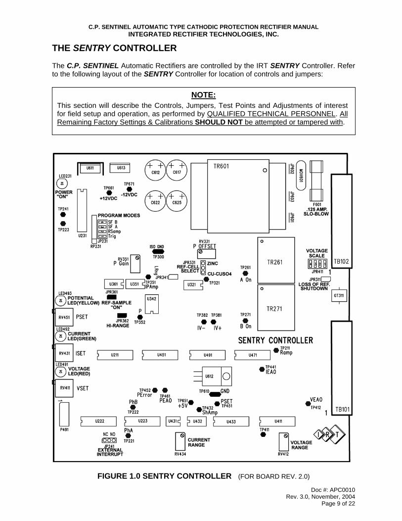
THE SENTRY CONTROLLER The C.P. SENTINEL Automatic Rectifiers are controlled by the IRT SENTRY Controller. Refer to the following layout of the SENTRY Controller for location of controls and jumpers:
FIGURE 1.0 SENTRY CONTROLLER (FOR BOARD REV. 2.0)
NOTE: This section will describe the Controls, Jumpers, Test Points and Adjustments of interest for field setup and operation, as performed by QUALIFIED TECHNICAL PERSONNEL. All Remaining Factory Settings & Calibrations SHOULD NOT be attempted or tampered with.
C.P. SENTINEL AUTOMATIC TYPE CATHODIC PROTECTION RECTIFIER MANUAL INTEGRATED RECTIFIER TECHNOLOGIES, INC.
Doc #: APC0010 Rev. 3.0, November, 2004
Page 10 of 22
CAUTION!! Do NOT attempt to alter the settings of any other trim pots on the controller board. Theseare factory calibrations and tampering with these settings could jeopardize proper operationand scaling of the SENTRY Controller.
CONTROLS: Voltage, Current, and Potential settings are adjusted via three potentiometers available on the SENTRY Controller. These potentiometers are 20-Turn trim-pots located at the end of the controller board opposite the wiring connectors. (Refer to Figure 1.0, Page 9). VOLTAGE: Rectifier output voltage (or Voltage Limit) is set by potentiometer “RV411”. Rectifier operation in Voltage Mode or Voltage Limit will be indicated by the Red LED “LED491”, adjacent the Voltage Set Potentiometer. CURRENT: Rectifier output current (or Current Limit) is set by potentiometer “RV431”. Rectifier operation in Current Mode or Current Limit will be indicated by the Green LED “LED492”, adjacent the Current Set Potentiometer. POTENTIAL: On rectifiers equipped with this option: Rectifier Structure to Reference Electrode Potential is set by potentiometer “RV451”, in conjunction with the “Press-to-Set/Actual” selector switch. Rectifier operation in the Potential Mode will be indicated by the Yellow LED “LED493”, adjacent the Potential Set Potentiometer. Both Potential Set Point and Actual Structure-Reference Electrode potential may be read on the rectifier’s potential meter via the “Press-to-Set/Actual” selector switch.
JUMPER SETTINGS: The SENTRY Controller is designed to adapt and accommodate a wide variety of field installations and control situations. To make this accommodation easier, please review the following Jumper functions and settings:
A. INPUT VOLTAGE SELECTION (JP601, JP602, & JP603)
INPUT VOLTAGE JP601 JP602 JP603 COMMENT
115 VAC INSTALLED INSTALLED OMITTED DEFAULT POSITION
230VAC OMITTED OMITTED INSTALLED OPTIONAL POSITION
NOTE: Depending upon the model and/or configuration of the rectifier ordered, one or more of these potentiometers may be mounted external of the controller board on the rectifier instrument panel. Consult your Rectifier Specification Sheet.
C.P. SENTINEL AUTOMATIC TYPE CATHODIC PROTECTION RECTIFIER MANUAL INTEGRATED RECTIFIER TECHNOLOGIES, INC.
Doc #: APC0010 Rev. 3.0, November, 2004
Page 11 of 22
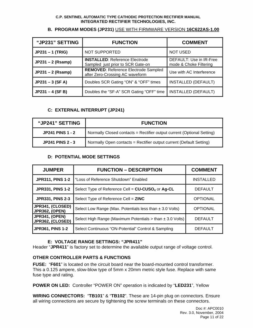
B. PROGRAM MODES (JP231) USE WITH FIRMWARE VERSION 16C622AS-1.00
C: EXTERNAL INTERRUPT (JP241)
D: POTENTIAL MODE SETTINGS
E: VOLTAGE RANGE SETTINGS: “JPR411”
Header “JPR411” is factory set to determine the available output range of voltage control. OTHER CONTROLLER PARTS & FUNCTIONS FUSE: “F601” is located on the circuit board near the board-mounted control transformer. This a 0.125 ampere, slow-blow type of 5mm x 20mm metric style fuse. Replace with same fuse type and rating. POWER ON LED: Controller “POWER ON” operation is indicated by “LED231”, Yellow WIRING CONNECTORS: “TB101” & “TB102”. These are 14-pin plug on connectors. Ensure all wiring connections are secure by tightening the screw terminals on these connectors.
“JP231” SETTING FUNCTION COMMENT
JP231 – 1 (TRIG) NOT SUPPORTED NOT USED
JP231 – 2 (Rsamp) INSTALLED: Reference Electrode Sampled just prior to SCR Gate-on
DEFAULT: Use in IR-Free mode & Choke Filtering
JP231 – 2 (Rsamp) REMOVED: Reference Electrode Sampled after Zero-Crossing AC waveform Use with AC Interference
JP231 – 3 (SF A) Doubles SCR Gating “ON” & “OFF” times INSTALLED (DEFAULT)
JP231 – 4 (SF B) Doubles the “SF-A” SCR Gating “OFF” time INSTALLED (DEFAULT)
“JP241” SETTING FUNCTION
JP241 PINS 1 - 2 Normally Closed contacts = Rectifier output current (Optional Setting)
JP241 PINS 2 - 3 Normally Open contacts = Rectifier output current (Default Setting)
JUMPER FUNCTION – DESCRIPTION COMMENT
JPR311, PINS 1-2 “Loss of Reference Shutdown” Enabled INSTALLED
JPR331, PINS 1-2 Select Type of Reference Cell = CU-CUSO4 or Ag-CL DEFAULT
JPR331, PINS 2-3 Select Type of Reference Cell = ZINC OPTIONAL
JPR341, (CLOSED) JPR362, (OPEN) Select Low Range (Max. Potentials less than ± 3.0 Volts) OPTIONAL
JPR341, (OPEN) JPR362, (CLOSED) Select High Range (Maximum Potentials > than ± 3.0 Volts) DEFAULT
JPR361, PINS 1-2 Select Continuous “ON-Potential” Control & Sampling DEFAULT
C.P. SENTINEL AUTOMATIC TYPE CATHODIC PROTECTION RECTIFIER MANUAL INTEGRATED RECTIFIER TECHNOLOGIES, INC.
Doc #: APC0010 Rev. 3.0, November, 2004
Page 12 of 22
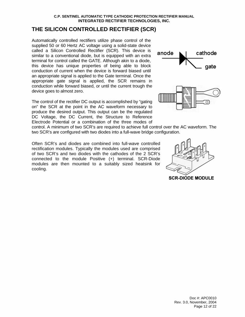
THE SILICON CONTROLLED RECTIFIER (SCR) Automatically controlled rectifiers utilize phase control of the supplied 50 or 60 Hertz AC voltage using a solid-state device called a Silicon Controlled Rectifier (SCR). This device is similar to a conventional diode, but is equipped with an extra terminal for control called the GATE. Although akin to a diode, this device has unique properties of being able to block conduction of current when the device is forward biased until an appropriate signal is applied to the Gate terminal. Once the appropriate gate signal is applied, the SCR remains in conduction while forward biased, or until the current trough the device goes to almost zero. The control of the rectifier DC output is accomplished by “gating on” the SCR at the point in the AC waveform necessary to produce the desired output. This output can be the regulated DC Voltage, the DC Current, the Structure to Reference Electrode Potential or a combination of the three modes of control. A minimum of two SCR’s are required to achieve full control over the AC waveform. The two SCR’s are configured with two diodes into a full-wave bridge configuration. Often SCR’s and diodes are combined into full-wave controlled rectification modules. Typically the modules used are comprised of two SCR’s and two diodes with the cathodes of the 2 SCR’s connected to the module Positive (+) terminal. SCR-Diode modules are then mounted to a suitably sized heatsink for cooling.
C.P. SENTINEL AUTOMATIC TYPE CATHODIC PROTECTION RECTIFIER MANUAL INTEGRATED RECTIFIER TECHNOLOGIES, INC.
Doc #: APC0010 Rev. 3.0, November, 2004
Page 13 of 22
POTENTIAL CONTROL AND EXTERNAL IR DROP In applying and operating IR-Drop Free C.P. SENTINEL Automatic Rectifiers, it is important that Cathodic Protection personnel are familiar with the methods & principles of using this type of rectifier to mitigate corrosion. Briefly described as follows: Current flowing in the measurement circuit will cause a voltage drop (referred to the Ohm’s Law equivalent of Current “I” multiplied by Resistance “R” or “IR”), which becomes incorporated into measurements as an error. In addition, any external currents flowing through the electrolyte in the area between the reference electrode and the structure will cause their own voltage drop, which also becomes part of the measurement as an additional error. Cathodic protection systems and AC & DC electrical power systems are some of the possible sources of these currents. The magnitude of errors from external IR drops can be substantial. To accurately maintain the required polarization potential on a given structure, these errors must be minimized during the design phase and then eliminated by electronic circuitry within the SENTRY Controller, which is used in the C.P. SENTINEL Automatic Rectifiers. The SENTRY Controller removes the IR drop error from the potential measurement by interrupting the cathodic protection current supplied by the rectifier momentarily. This action produces an instantaneous voltage drop, which is considered to be the external IR Drop. The potential from Reference Electrode to Structure is measured immediately after this instantaneous drop, and is considered to be the "IR Drop Free" potential of the structure. Clearly, this method only works with an impressed current cathodic protection system where all the rectifiers on that system can be interrupted simultaneously, and there are no other sources of current flowing through the electrolyte. An issue that should be considered when using current interruption for instant-off measurements is: What is meant by instantaneous? The answer is not simple since it depends upon the structure, the electrolyte and the method of interrupting the current. Putting the answer in electrical terms, it depends upon the capacitance and the inductance of the circuit. IR drop free measurements can be made microseconds after current interruption on small, uncoated specimens in a low resistance electrolyte. Large coated structures, such as pipelines, or high resistance electrolytes, such as concrete, usually require several hundred milliseconds or more for IR-drop free measurements. Interrupting current on the AC side rather than on the DC side of the rectifier will increase the time delay because the circuit inductance is higher. An oscilloscope should be used if measurement precision is necessary; it should be either battery powered or connected through an isolation transformer to eliminate ground loops.
NOTE: This section applies only to C.P. SENTINEL Automatic Rectifiers which have been ordered and manufactured to function as IR-Drop Free Reference Electrode controlled outputs. Consult your Rectifier Specification Sheet.
C.P. SENTINEL AUTOMATIC TYPE CATHODIC PROTECTION RECTIFIER MANUAL INTEGRATED RECTIFIER TECHNOLOGIES, INC.
Doc #: APC0010 Rev. 3.0, November, 2004
Page 14 of 22
GENERAL COMPONENT DESCRIPTION When operating any equipment, it is a good practice to become familiar with the key components and the general operation of that piece of equipment. The following is a summary of the key components of a rectifier and their function: The AC Input Surge Arrestor is a device that protects the rectifier components from voltage surges that may occur across the AC input of the rectifier. It does this by providing a bypass circuit for the resultant current from these high voltage surges after a specific voltage threshold has been reached. Most surge arrestors are designed to handle a certain number or energy value of surges prior to failing. The rectifier AC Input Circuit Breaker (CB1) is a fully magnetic type that serves three key functions. It is used as an “OFF-ON” switch for the rectifier, it provides “short circuit” protection, and, to a lesser degree, provides input overload protection. The rectifier Main Transformer (T1) provides full electrical isolation between the utility AC power and the Cathodic Protection DC circuit. It also steps the voltage up or down as required for the DC circuit and, for tap type units, provides a means of output adjustment. The rectifier AC Secondary Fuse is a time lag or slow-blow type that provides protection from not only short-circuits or overloads in the DC output circuit but also in the diode bridge circuit. The rectifier SCR-Diode Bridge Assembly is comprised of silicon controlled diodes (SCR’s) and diodes configured into a full-wave bridge configuration. The SCR-diodes are supplied with suitably sized heatsinks to ensure that the SCR-diodes do not exceed 100°C at full rated output. The SCR-diode bridge controls and rectifies the AC secondary voltage of the transformer into DC voltage that can be used for Cathodic Protection. This DC voltage level is then automatically maintained by the SENTRY Controller in Potential, Current or Voltage Mode, as set by the operator. A Varistor is supplied across the AC input to the diode bridge to provide additional protection from any voltage surges that may pass the main AC surge arrestor or be developed by the main transformer. A second varistor may also be supplied across the DC output of the diode bridge at special request. The Current Monitoring Shunt is a block style calibrated resistor with an accuracy of 0.25%. The DC current and voltage rating are stamped into the body of the shunt. Shunts used in rectifiers equipped with digital meters will be either 1 Millivolt or 10 Millivolts per ampere, depending upon the rectifier output current rating. The rectifier Ammeter & Voltmeter utilize an analog, taut-band type movement that provides ±2% accuracy. The DC output amperage of the rectifier is monitored by a meter connection across the calibrated test screws of the above shunt. The DC output voltage of the rectifier is monitored by a meter connection across the DC output terminals of the rectifier. On Potential Controlled rectifiers, an additional Potential Meter is supplied to monitor the Structure to Reference Cell Potential, and the desired “Set Potential”. This meter receives the potential reading from the SENTRY Controller.
C.P. SENTINEL AUTOMATIC TYPE CATHODIC PROTECTION RECTIFIER MANUAL INTEGRATED RECTIFIER TECHNOLOGIES, INC.
Doc #: APC0010 Rev. 3.0, November, 2004
Page 15 of 22
Potential Adjust Potentiometer is a front, panel-mounted multi-turn potentiometer used to set the required Structure to Reference Electrode potential required by the CP System. The setting can be read on the Potential Meter by activating the Potential Switch to the “Set” position. The “Set-Actual” Switch permits the operator to monitor, via the rectifier Potential Meter, either the “Actual“ potential or the “Set” potential of the rectifier. The “Actual” potential may be either free of IR-Drop error, as determined by the SENTRY Controller, or the “ON” potential, if the rectifier is equipped with filtering or if configured to operate in the ”ON” potential Mode. Metering Test Points (Optionally supplied) are located on the touch-safe instrument panel for purposes of verifying the digital meter readings. Metering Test Points are 0.093 diameter test jacks, with polarity and function as indicated by the silk screening on the panel. The “Potential” test points will indicate the potential voltage reading as determined by the “POTENTIAL ACTUAL/SETPOINT” toggle switch. The Reference Electrode (Cell) – Structure Input Terminal Block is used to make field connections to the CP system Reference Cell and Structure sensing leads. External Interrupt Terminal Block: (NOT Supplied on IR-Free rectifiers) Two terminals are provided on the front panel of the rectifier for purposes of interrupting the rectifier output using the SENTRY Controller. Jumper “JP241” on the controller board as required for Normally Open equals rectifier “ON” or Normally Closed contacts equals “rectifier “ON” as dictated by the interrupter being used. This is the preferred method to interrupt the rectifier by an external means. Special circuitry in the SENTRY Controller retains all of the operating parameters for resumption of control parameters after conclusion of an interrupt procedure and will not reset the slow start circuitry. The DC Output Surge Arrestor is a device that protects the rectifier components from voltage surges that may occur across the DC output of the rectifier. It’s operation and characteristics are similar to the AC input surge arrestor. As many optional features / components are available for our customers, it is not practical for this manual to describe all of the possible options in detail. As such, it is recommended that the rectifier data sheet and the electrical schematic be reviewed in detail to become familiar with any features not detailed in this manual.
APPLICATION ALERT!! IR-Free Automatic Potential controlled rectifiers typically do not utilize external interrupters when operating. For proper IR-Free potential control, the SENTRY Controller must not be impeded by external interrupter cycles as it controls the desired “Set Potential” of the CP system.
NOTE: If no reference electrode is used, a jumper should be placed across these input terminals.
C.P. SENTINEL AUTOMATIC TYPE CATHODIC PROTECTION RECTIFIER MANUAL INTEGRATED RECTIFIER TECHNOLOGIES, INC.
Doc #: APC0010 Rev. 3.0, November, 2004
Page 16 of 22
INITIAL ENERGIZATION After the rectifier has been properly connected to the AC supply and the DC output cables, (and Reference Electrode – Structure Sensing leads in the case of a potentially controlled type of rectifier) it is ready to be energized. Before energizing, always double-check both the AC and DC connections to ensure they are properly connected. Ensure that for dual input rectifiers (115 / 230 or 230 / 460 VAC), the AC input terminal jumpers are properly configured for the actual AC input voltage being supplied and that the AC input wires are connected to the proper terminals. For Current Controlled rectifiers, ensure that the rectifier is at its lowest control setting, by adjusting the “Current Adjust” potentiometer to zero. Use a multi-meter to verify static Reference Electrode – Structure potentials and record for later reference.
ENERGIZATION ALERT!!
If the rectifier is to be used on a CP system protecting the inside of a vessel ensure the vessel contains fluid sufficient to cover the anode system and the Reference Electrode.
Place the AC fused disconnect switch to the “ON” position and measure across the rectifier AC input terminals to ensure the voltage present is as expected. Next, place the rectifier AC input circuit breaker also to the “ON” position. The “POWER ON” Yellow LED on the SENTRY Controller will illuminate. The SENTRY Controller is designed with a “slow start” circuitry to minimize in-rush currents and to prevent the rectifier from starting at full output. This slow start time period will last from 3 – 10 seconds. There will be some deflection on the panel meters, especially the Potential Meter (although this deflection may be quite minimal on the Ammeter and Voltmeter). For units with a metering switch, ensure to set this switch to the “ON” position. For Automatic Current rectifiers, simply adjust the “Current Adjust” potentiometer to the required current. This current will be read on the rectifier Ammeter. The rectifier ammeter can be verified by measuring the voltage (in Millivolts) across the calibrated test screws of the rectifier shunt (not across the connection bolts). To determine the current through the shunt from the millivolt reading taken, the following formula can be used: DC Current (I) = Measured Shunt Voltage (Millivolts) X Rated Shunt Current Rated Shunt Voltage (50 Millivolts typical) Note: Rated shunt current and voltage values are stamped onto the body of the shunt
and are also shown on the rectifier data page. The ammeter can also be verified with an external DC clamp-on type meter, if available. It is recommended that all initial energization readings be recorded for future reference. Useful readings to record are structure potential levels prior to energization, AC input voltage & current, DC output voltage and current, tap or adjustment dial setting, structure potential levels after energization, as well as any observed problems or possible future concerns with the installation, in general. For Automatic Potential Rectifiers, activate the Potential Switch to the “SET” position and observe the “SET” level of potential control on the Potential Meter. Adjust the required potential control level with the Potential Adjust potentiometer to the desired level of control. Release the Potential Switch and observe the “Actual” potential on the Potential Meter. When operating in this mode, the Yellow LED will be illuminated. It is important to note that if the
C.P. SENTINEL AUTOMATIC TYPE CATHODIC PROTECTION RECTIFIER MANUAL INTEGRATED RECTIFIER TECHNOLOGIES, INC.
Doc #: APC0010 Rev. 3.0, November, 2004
Page 17 of 22
A NOTE ABOUT POTENTIAL READINGS!! The SENTRY Controller is designed to provide IR-Free potential readings for control and for display to the Potential Meter. This reading will differ from the measured Structure–Reference Electrode inputs into the rectifier by the IR-Drop error. (Refer to description on Page 13) The “Actual” potential from the SENTRY Controller will only correspond to the measured Structure–Reference Electrode inputs into the rectifier with no current flowing; i.e.: at no load. On rectifiers equipped with efficiency filters, true IR-Free operation cannot be attained. The “Actual” potential will equate to the Structure–Reference Electrode potential with minimal IR-Free error.
potential control “Set” level cannot be initially attained due to the polarization time of the Structure, the rectifier will ramp up the DC output to either the Voltage set point (Voltage Limit; Red LED illuminated) or the Current set point (Current Limit; Green LED illuminated). Once the potential control “Set” level is attained, the SENTRY Controller will automatically revert into Potential Mode and maintain the Structure to Reference Electrode potential at the preset level. The Yellow LED will then be illuminated.
Rectifiers equipped with MANUAL MODE Option: Adjustment of rectifiers equipped with this option requires the “Automatic-Manual” selector switch be switched to the “Manual” position. Start the rectifier with the Coarse & Fine taps set to their lowest level (Coarse “A” – Fine “1”). Observe and record if necessary the rectifier output currents and voltage levels, and the polarization level of the Structure being protected. Incrementally, increase the transformer tap settings until either target current or polarization levels are attained. The SENTRY Controller is NOT required for manual mode, and may be removed for repair if it is not functioning correctly. After the structure potential readings have been taken and prior to leaving the site, it is recommended that the DC output connections to the rectifier be rechecked to ensure a secure connection. It is also beneficial to recheck the rectifier to ensure that all air inlet and outlet venting on the enclosure is not obstructed in any manner. The rectifier O&M manual should be securely set in it’s holder (for small rectifiers without a manual holder, it is recommended that the manual be kept with the main operator or in the control room of the closest station). Also verify that all holes within the enclosure (other than the venting screens) are suitably plugged (such as unused conduit knockouts). For rectifier units with “OFF-ON” meter switches, ensure that the switch is in the “OFF” position prior to leaving the site.
APPLICATION NOTES:
1. Remember, the C.P. SENTINEL AQUA-LINE rectifiers are equipped with “Loss-of-Reference” shutdown feature. The rectifier “REFERENCE SELECT” switch must be set to sense an active and functional Reference Cell input or no output will occur from the unit. Alternately, jumper the “REF. CELL” inputs on the front of the rectifier panel to obtain a current output. A “Loss-of-Reference” shutdown will be evident by the digital Potential Meter reading overload; first digit a “1” followed by remaining digits blank.
2. To function in current mode up to rated current, the output of the rectifier cannot be
limited by either the “VOLTAGE SET” or the “POTENTIAL SET” potentiometers.
C.P. SENTINEL AUTOMATIC TYPE CATHODIC PROTECTION RECTIFIER MANUAL INTEGRATED RECTIFIER TECHNOLOGIES, INC.
Doc #: APC0010 Rev. 3.0, November, 2004
Page 18 of 22
REGULAR MAINTENANCE & ADJUSTMENT The basis for any effective CP system is routine documentation & maintenance. Despite the rectifier maintaining the DC output “automatically”, it is recommended that the rectifier be checked and adjusted if necessary at least twice per year. Some local regulatory bodies require a monthly or semi-monthly check to ensure proper protection levels are being maintained. These checks also allow you to ensure that the rectifier has not been damaged. When completing this maintenance and adjustment check, it is recommended that all readings and observations be recorded in the site file. With regular maintenance checks and by maintaining good records, future troubleshooting and repair costs can be reduced. Prior to arriving at the site for the rectifier maintenance check, it is recommended that the technician review the existing rectifier site file to gain familiarization with the subject rectifier and site conditions. Upon arriving at the rectifier site, a visual check should be completed to determine if any changes have occurred. Things to look for are signs of new underground construction, buildings, pipeline tie-ins, bonds, etc. Prior to adjustment of the rectifier, it is recommended that structure potential readings be taken, to determine the adjustment level required. Even if the potential levels are within the required range, the rectifier should still be checked for proper operation. When approaching the rectifier, ensure that no items have been placed near the rectifier enclosure in such a manner as to block the venting, either on the bottom or sides. As the vent openings on the rectifier enclosure are screened, there should be no refuse inside from birds or larger insects. However, after opening the door of the enclosure, ensure that there has been no significant accumulation of dirt, snow, or other small debris at the bottom of the enclosure, which may adversely affect proper venting. DO NOT INSTALL, REMOVE, or REWIRE THIS EQUIPMENT WITH POWER APPLIED!! Prior to any adjustment of the rectifier, measure and record the “As Found” readings of the rectifier (DC voltage, DC amperage, etc.). Next, set the rectifier circuit breaker and the utility disconnect to the “OFF” position to allow for a detailed rectifier inspection. At least once a year the rectifier should be inspected for loose electrical connections that could eventually cause damage to the electrical panel, wiring, or rectifier components. If an electrical connection becomes loose, the resistance of the connection increases and causes it to heat up. This additional heat will cause the connection to oxidize and become even higher resistant until a failure occurs. The best way to check for a heated connection is with a temperature probe, however, as these are not typically standard issue for Cathodic field maintenance, the visual inspection method will suffice. First, visually inspect all of the main electrical connections within the rectifier for signs of discoloration on the connection terminal, the electrical panel, or the wire attached to the terminal. Key points to check are the DC output lug terminal connections and the fuse holder connections. If you see a suspect connection, use a wrench or other suitable tools to see if the connection is indeed loose. (Note: Be careful when touching these types of connections with your hand as the temperature of loose high current connections can cause a significant burn.) If you do find a loose connection, it should be secured with suitable tools (make sure to secure both the front and rear of the double-nutted panel connections). If a loose connection has already caused damage to the electrical panel, the panel should be repaired or replaced, as re-tightening a connection on a degraded panel will most likely still lead to a future failure.

C.P. SENTINEL AUTOMATIC TYPE CATHODIC PROTECTION RECTIFIER MANUAL INTEGRATED RECTIFIER TECHNOLOGIES, INC.
Doc #: APC0010 Rev. 3.0, November, 2004
Page 19 of 22
Certain main components within the rectifier should also be inspected for signs of over-heating or other damage. The main isolation transformer (T1) within the rectifier is designed to operate at a fairly high temperature and thus is usually somewhat discoloured. However, it should not be extremely dark or black. If it is, this could indicate insufficient / blocked venting or a problem within the transformer itself. The AC primary, AC secondary, and the DC output surge arrestors should be checked to ensure that a significant voltage surge has not damaged them. Signs of damage to an arrestor device are usually visually noticeable by a blackened or cracked housing. Please note however that sometimes the operational status of an arrestor is not discernable visually and requires further checking (see Troubleshooting section). The rectifier fusing should also be checked for overheating. If the fusing is a bolt-on type (for larger rectifier units), ensure that the fastening studs or bolts are secure on both the front and rear. Many smaller rectifier units utilize the “clip-type” fuse connectors that are very convenient for fuse replacement but are also infamous for becoming loose and oxidizing over time. However, with regular checks and maintenance, problems can be avoided. For this type of connection, if oxidation is apparent, the fuse should be removed and both the fuse and the fuse contact surface of the clips cleaned up with some very fine sand paper or emery cloth (only the oxidation layer should be removed, not the protective coating on the copper). If the fuse clips have lost tension, they should be replaced. If replacements are not immediately available, the clips can be “squeezed” together and should then provide a suitable short-term connection to the fuse. A notation should be made however, in the site inspection form for replacement on the next maintenance check. The connection hardware on each fuse clip should also be checked and re-tightened if necessary. If, after completing the inspection on the rectifier unit, a problem is found other than just a loose connection, refer to the “Troubleshooting” section of this manual. If no problems have been found, the rectifier can be adjusted to a new DC output setting (if deemed required based on the “as-found” structure potential levels). As per the adjustment procedure indicated in the “Initial Energization” section, adjust the DC output of the rectifier to the level required to provide suitable protection to the structure. If the rectifier is adjusted to or near it’s maximum rated output, future replacement of the rectifier with a larger unit or the addition of anodes may need to be considered. If the required “target” DC output current from the rectifier varies significantly over the year due to load resistance changes, maintenance checks should be done frequently.
C.P. SENTINEL AUTOMATIC TYPE CATHODIC PROTECTION RECTIFIER MANUAL INTEGRATED RECTIFIER TECHNOLOGIES, INC.
Doc #: APC0010 Rev. 3.0, November, 2004
Page 20 of 22
TROUBLESHOOTING If a problem is found with the rectifier during the maintenance inspection or reported by the local operator, the following troubleshooting procedure can be followed to determine the cause. The only way to effectively determine the cause of a failure in any piece of equipment is to conduct a systematic analysis of the function and operation of the key components. For this troubleshooting procedure, we shall review the possible faults that may occur starting from the DC output and working back to the AC input. Please refer to the Rectifier Specifications Sheet, Electrical Schematic supplied with each rectifier and to the SENTRY Controller layout on Page 9 of this manual for component descriptions and test points. Common rectifier failures can be summarized and corrected as follows: A. NO RECTIFIER OUTPUT CURRENT: This fault may be caused by any one or more of the
following conditions:
No AC Present: Check incoming utility supply for the presence of voltage and that it is correct for the rating of the rectifier. Consult your electrician or electrical utility to correct this problem.
Rectifier AC Breaker Tripped: First: Do a visual inspection as described in the Maintenance & Adjustment section of this manual. Secondly, attempt to reset the breaker and observe rectifier output. If the rectifier fails to function correctly, continue with this troubleshooting procedure.
Blown Fuse: Check all rectifier fuses, including the control fuse located on the SENTRY Controller circuit board. Replace as required with the identical type, size and rating as supplied. One spare for each fuse used in the unit is supplied with each rectifier.
Check Interrupt Circuit: It is possible for field attached external interrupter to hold the output “Off”. Refer to Page 11, Section “C” and Page 15 “External Interrupt Terminal Block” and correct any possible interrupter setting errors.
Improper Settings: Review the settings on the SENTRY Controller for Voltage, Current and Potential (if applicable). Any one of these potentiometers set to “zero” will result in no rectifier output. Review “Controls” section of this manual on Page 10, and correct any setting errors.
SENTRY Controller Failure: Check for the board status LED’s. “Power ON” LED is illuminated continually when the board is powered and the on-board microprocessor is functioning. One of the Mode LED’s will function if any one of the rectifier output modes is being controlled. Due to board complexity, replace defective controller with a known working controller.
CAUTION!! Please be advised that hazardous voltages are present within the rectifier unit even with the rectifier AC input circuit breaker in the “OFF” position. Extreme care should be observed when taking measurements on the front of the instrument panel or the side AC input panel. Only qualified electronic or electrical technicians should attempt internal troubleshooting of the rectifier. The fused AC disconnect should be set to the “OFF” position prior to any internal rectifier maintenance or repair.

C.P. SENTINEL AUTOMATIC TYPE CATHODIC PROTECTION RECTIFIER MANUAL INTEGRATED RECTIFIER TECHNOLOGIES, INC.
Doc #: APC0010 Rev. 3.0, November, 2004
Page 21 of 22
Faulty Connections: Often broken or high resistance connections will lead to no rectifier output or intermittent output. Disconnect power, check and re-tighten all connections. Be especially aware of any oxidized, burnt or discoloured connections. Repair or replace as required.
DC voltage at output lugs, but no current: The principle reason for this failure is a broken CP system cables beyond the rectifier. Investigate and repair broken cables.
DC voltage at output lugs, current flowing to load, but no current reading on ammeter: This could be the result of a defective ammeter, faulty leads, or failure of a metering switch. Repair or replace defective components.
Failure of Reference Electrode: The SENTRY Controller is equipped with “Loss of Reference Electrode” shut-down circuitry to prevent coating damage due to excessive polarization upon failure Reference Electrode. Replace defective Reference Electrode and re-energize rectifier. Refer to Page 7.
B. LIMITED RECTIFIER OUTPUT CURRENT: This fault may be caused by any one or more
of the following conditions:
Improper Mode settings on the SENTRY controller resulting in insufficient current to the CP system. Re-check settings and limits for current, voltage and potential (If applicable).
Load resistivity too high for rating of the rectifier. This will usually be indicated by a “Voltage Limit” condition; where the Red LED is illuminated. Check anodes and ground bed resistance. Modify if necessary, or replace rectifier with a higher rated unit.
Low supply voltage: Check incoming AC voltage to rectifier while rectifier is under load. Consult electrical maintenance personnel for adjustment if line voltage is low.
Excessive AC interference on Reference Electrode to Structure inputs may reduce the rectifier DC output (on Potential controlled rectifiers). Although equipped with circuitry to minimize AC interference on the potential measuring circuit, excessive amounts of interference can cause the SENTRY Controller to reduce output current or voltage in response to this outside interference. Review installation practices outlined on Page 7.
Failure of SCR-Diode module: could result in “half-wave” output, which will yield only half of the rated output. Replace defective module with replacement.
Failure of the SENTRY Controller board. Remove defective board & replace with known working control board.
C. POTENTIAL SET POINT NOT MAINTAINED: This fault may be due to one or more of the
following conditions:
Rectifier output being limited by either the Voltage Limit or the Current Limit. Adjust these limits to the maximum rating of the rectifier.
Rectifier output being limited by the Manual Tap adjustment (On rectifiers equipped with this option) Sufficient voltage must be supplied from the transformer taps to maintain the set point potential.
Failure of the Reference Electrode results in limited or no output. See Page 7. Excessive AC input on Reference Cell – Structure leads. See Item “B”, above. Defective “Press-to-Set” selector switch. Oxidized contacts could result in the
“Set Potential” not being switched correctly into the SENTRY Controller.
C.P. SENTINEL AUTOMATIC TYPE CATHODIC PROTECTION RECTIFIER MANUAL INTEGRATED RECTIFIER TECHNOLOGIES, INC.
Doc #: APC0010 Rev. 3.0, November, 2004
Page 22 of 22
D. RECTIFIER FUSE BLOWS: Fuse failure may be due to the following:
Fuses may blow due to either excessive current. In an automatic rectifier, this type of failure is mainly due to failure in the SCR-Diode module. Replace failed module and fuse, and re-energize rectifier.
Fuses may blow due to excessive operating temperature. Excessive temperature on the fuse is typically caused by either corrosion or weakening of the gripping tension on the fuse clips or fuse holder. Replace defective fuse components when this occurs.
E. RECTIFIER AC BREAKER TRIPS: AC Breaker tripping may be resolved as follows:
Visually inspect the rectifier AC input surge arrestor for damage (usually located adjacent to the AC input terminals). If the housing of the arrestor is cracked or blackened, the arrestor has failed and should be replaced. Always replace the arrestor with one of the same type. If an immediate replacement cannot be obtained, the rectifier can operate without this arrestor for a limited period, however, please remember that the rectifier then has no protection against surges. In certain circumstances, the arrestor may also fail without any external signs of damage. As such, to ensure that the AC arrestor is not the problem and with the AC power “OFF”, disconnect the wires of the arrestor from the circuit breaker terminals. If the rectifier circuit breaker now remains in the “ON” position when energized, the arrestor has failed and should be replaced.
If the breaker still trips to the “OFF” position, disconnect the wires between output (bottom) terminals of the rectifier circuit breaker (CB1) and the AC primary of the main transformer (T1). If the rectifier circuit breaker now remains in the “ON” position when energized, the problem is further downstream in the rectifier.
Reconnect the wires in the step above. Remove the wires from the transformer secondary to the SCR-Diode module. Note: This may be accomplished by open-circuiting the rectifier secondary fuse; if so equipped. If the breaker still trips to the “OFF” position, the main transformer has most likely failed and should be replaced (consult the factory for a replacement).
Another possibility is that the AC configuration terminals of the main transformer (T1) (for dual input types only) are incorrectly set for the actual AC input voltage applied to the rectifier. Please confirm that these terminals are configured properly (refer to the electrical schematic) for the AC voltage being applied.
The final possibility is most likely that the rectifier AC input circuit breaker itself has failed and will require replacement.
F. RECTIFIER OUTPUT IS INTERMITTENT: Possible causes for erratic are:
Broken or loose connections. Check all rectifier connections for loose or broken connections. Include the wiring connections to the SENTRY Controller.
Check if built-in or field attached interrupters are in operation.
TROUBLESHOOTING SUMMARY: As rectifier problems in automatic units can be more easily solved by having a good working knowledge of the application and the workings of the rectifier, review this manual to ensure recommended installation practices have been followed. If a problem cannot be solved, please contact your rectifier dealer or the factory for technical assistance.