Embed Size (px)
Citation preview

CP Gun/Servo 2KDual-PCI Controllerwith Integrated
Temperature Conditioning
Manual 1062962A--02Issued 11/07
NORDSON CORPORATION AMHERST, OHIO USA
Part 1062962A--02 E 2007 Nordson Corporation
Safety 1. . . . . . . . . . . . . . . . . . . . . . . . . . . . . . . . . . . . . .Qualified Personnel 1. . . . . . . . . . . . . . . . . . . . . . . .Intended Use 1. . . . . . . . . . . . . . . . . . . . . . . . . . . . . .Regulations and Approvals 1. . . . . . . . . . . . . . . . . .Personal Safety 1. . . . . . . . . . . . . . . . . . . . . . . . . . . .
High-Pressure Fluids 1. . . . . . . . . . . . . . . . . . . .Fire Safety 2. . . . . . . . . . . . . . . . . . . . . . . . . . . . . . . .
Halogenated Hydrocarbon Solvent Hazards 2.Action in the Event of a Malfunction 2. . . . . . . . . .Disposal 2. . . . . . . . . . . . . . . . . . . . . . . . . . . . . . . . . .
Description 3. . . . . . . . . . . . . . . . . . . . . . . . . . . . . . . . . .Theory of Operation 3. . . . . . . . . . . . . . . . . . . . . . . . .
Temperature Conditioning 3. . . . . . . . . . . . . . . .Alarms 3. . . . . . . . . . . . . . . . . . . . . . . . . . . . . . . . .
Water Treatment 6. . . . . . . . . . . . . . . . . . . . . . . . . . .Water Types 6. . . . . . . . . . . . . . . . . . . . . . . . . . . .Corrosion Levels 6. . . . . . . . . . . . . . . . . . . . . . . . .Biocide Water Treatment 6. . . . . . . . . . . . . . . . . .
Installation 8. . . . . . . . . . . . . . . . . . . . . . . . . . . . . . . . . .Guidelines 8. . . . . . . . . . . . . . . . . . . . . . . . . . . . . . . . .Configure the Robot Controller 8. . . . . . . . . . . . . . .
Analog #1 8. . . . . . . . . . . . . . . . . . . . . . . . . . . . . . .Analog #2 8. . . . . . . . . . . . . . . . . . . . . . . . . . . . . . .
Set Servo 2K Timing Sequences 9. . . . . . . . . . . . . .Servo 2K RS4 Signal Sequence 9. . . . . . . . . . .Servo 2K Non-RS4 Signal Sequence 10. . . . . . .
Servo 2K Auto-Purge Feature 11. . . . . . . . . . . . . . .Servo 2K Prepressure Setpoints 11. . . . . . . . . . . . .Set CP Gun Timing Sequences 12. . . . . . . . . . . . . . .
CP Gun RS4 Signal Sequence 12. . . . . . . . . . . .CP Gun Non-RS4 Signal Sequence 13. . . . . . . .
Operator Interface and Screens 14. . . . . . . . . . . . . . .SYSTEM STATUS 14. . . . . . . . . . . . . . . . . . . . . . . . . .VIEW FAULTS 16. . . . . . . . . . . . . . . . . . . . . . . . . . . . .TEST POINTS 18. . . . . . . . . . . . . . . . . . . . . . . . . . . . .SYSTEM SET-UP 19. . . . . . . . . . . . . . . . . . . . . . . . . .
Flow Meter 20. . . . . . . . . . . . . . . . . . . . . . . . . . . . . .Flow Meter Encoder Test 21. . . . . . . . . . . . . . . . . .Purge 22. . . . . . . . . . . . . . . . . . . . . . . . . . . . . . . . . .CP Gun Delays 23. . . . . . . . . . . . . . . . . . . . . . . . . .Clock 24. . . . . . . . . . . . . . . . . . . . . . . . . . . . . . . . . . .System 25. . . . . . . . . . . . . . . . . . . . . . . . . . . . . . . . .Pump Stand 1 26. . . . . . . . . . . . . . . . . . . . . . . . . .Restore Configuration 27. . . . . . . . . . . . . . . . . . . .Simulation Mode 28. . . . . . . . . . . . . . . . . . . . . . . . .Temperature Setpoint 29. . . . . . . . . . . . . . . . . . . .Temperature Status 30. . . . . . . . . . . . . . . . . . . . . .Servo 2K SYSTEM SET-UP 31. . . . . . . . . . . . . . .
PROCESS DATA 33. . . . . . . . . . . . . . . . . . . . . . . . . . .Servo 2K PROCESS DATA Part Charts 34. . . .
ONLINE MANUALS 35. . . . . . . . . . . . . . . . . . . . . . . . .PREV. MAINT. 36. . . . . . . . . . . . . . . . . . . . . . . . . . . . .BEAD SIZE 37. . . . . . . . . . . . . . . . . . . . . . . . . . . . . . . .
Operation 38. . . . . . . . . . . . . . . . . . . . . . . . . . . . . . . . . . .Start the Temperature Conditioning Unit 39. . . . . . .
Verify Pipe and RTD Connections 39. . . . . . . . .Fill the Water Reservoir 39. . . . . . . . . . . . . . . . . . . . .Start the Controller 40. . . . . . . . . . . . . . . . . . . . . . . . .
CP Gun System 40. . . . . . . . . . . . . . . . . . . . . . . . .Servo 2K System 42. . . . . . . . . . . . . . . . . . . . . . . .
Dispense Material 42. . . . . . . . . . . . . . . . . . . . . . . . . .Fault Messages 42. . . . . . . . . . . . . . . . . . . . . . . . . . . .CP Gun Alarm Settings 44. . . . . . . . . . . . . . . . . . . . .Servo 2K Statistical Process Control Data 45. . . . .
Servo 2K SPC Error and SystemStatus Codes 45. . . . . . . . . . . . . . . . . . . . . . . . . . .
CP Gun Statistical Process Control Data 45. . . . . .Accessing SPC Data 45. . . . . . . . . . . . . . . . . . . . . . .Adjusting the Chilled Water Flow 46. . . . . . . . . . . . .Shutdown 47. . . . . . . . . . . . . . . . . . . . . . . . . . . . . . . . .
Maintenance 48. . . . . . . . . . . . . . . . . . . . . . . . . . . . . . . .Troubleshooting 49. . . . . . . . . . . . . . . . . . . . . . . . . . . . .
Servo 2K System Problems 49. . . . . . . . . . . . . . . . . .CP Gun System Problems 51. . . . . . . . . . . . . . . . . . .Temperature Conditioning System 52. . . . . . . . . . . .Cable Continuity 55. . . . . . . . . . . . . . . . . . . . . . . . . . . .
Repair 56. . . . . . . . . . . . . . . . . . . . . . . . . . . . . . . . . . . . . . .Operator Interface Panel 56. . . . . . . . . . . . . . . . . . . .Typical PCA Replacement 56. . . . . . . . . . . . . . . . . . .Restoring PCIController Programs 58. . . . . . . . . . . . . . . . . . . . . . .Saving and Loading PCI Controller Configurations . . .60
Saving Configurations 60. . . . . . . . . . . . . . . . . . . .Loading Configurations 61. . . . . . . . . . . . . . . . . . .
Parts 62. . . . . . . . . . . . . . . . . . . . . . . . . . . . . . . . . . . . . . . .Temperature Conditioning Sections 63. . . . . . . . . . .Accessories and Kits 64. . . . . . . . . . . . . . . . . . . . . . . .Cables 64. . . . . . . . . . . . . . . . . . . . . . . . . . . . . . . . . . . .CorrShield MD405 64. . . . . . . . . . . . . . . . . . . . . . . . . .
Specifications 64. . . . . . . . . . . . . . . . . . . . . . . . . . . . . . .Schematics and Wiring Diagrams 64. . . . . . . . . . . . .
Contact UsNordson Corporation welcomes requests for information, comments, andinquiries about its products. General information about Nordson can befound on the Internet using the following address:http://www.nordson.com.Address all correspondence to:
Nordson CorporationAttn: Customer Service555 Jackson StreetAmherst, OH 44001
NoticeThis is a Nordson Corporation publication which is protected by copyright.Original copyright date 2005. No part of this document may bephotocopied, reproduced, or translated to another language without theprior written consent of Nordson Corporation. The information containedin this publication is subject to change without notice.
Trademarks
Nordson and the Nordson logo are registered trademarksof Nordson Corporation.
All other trademarks are the property of their respective owners.
CP Gun/Servo 2K Dual-PCI Controller with Integrated Temperature Conditioning 1
Part 1062962A−02� 2007 Nordson Corporation
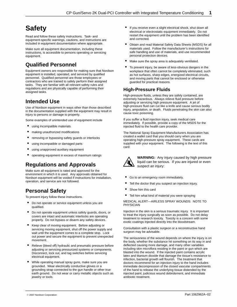
Safety Read and follow these safety instructions. Task- andequipment-specific warnings, cautions, and instructions areincluded in equipment documentation where appropriate.
Make sure all equipment documentation, including theseinstructions, is accessible to persons operating or servicingequipment.
Qualified Personnel Equipment owners are responsible for making sure that Nordsonequipment is installed, operated, and serviced by qualifiedpersonnel. Qualified personnel are those employees orcontractors who are trained to safely perform their assignedtasks. They are familiar with all relevant safety rules andregulations and are physically capable of performing theirassigned tasks.
Intended Use Use of Nordson equipment in ways other than those describedin the documentation supplied with the equipment may result ininjury to persons or damage to property.
Some examples of unintended use of equipment include
� using incompatible materials
� making unauthorized modifications
� removing or bypassing safety guards or interlocks
� using incompatible or damaged parts
� using unapproved auxiliary equipment
� operating equipment in excess of maximum ratings
Regulations and Approvals Make sure all equipment is rated and approved for theenvironment in which it is used. Any approvals obtained forNordson equipment will be voided if instructions for installation,operation, and service are not followed.
Personal Safety To prevent injury follow these instructions.
� Do not operate or service equipment unless you arequalified.
� Do not operate equipment unless safety guards, doors, orcovers are intact and automatic interlocks are operatingproperly. Do not bypass or disarm any safety devices.
� Keep clear of moving equipment. Before adjusting orservicing moving equipment, shut off the power supply andwait until the equipment comes to a complete stop. Lockout power and secure the equipment to prevent unexpectedmovement.
� Relieve (bleed off) hydraulic and pneumatic pressure beforeadjusting or servicing pressurized systems or components.Disconnect, lock out, and tag switches before servicingelectrical equipment.
� While operating manual spray guns, make sure you aregrounded. Wear electrically conductive gloves or agrounding strap connected to the gun handle or other trueearth ground. Do not wear or carry metallic objects such asjewelry or tools.
� If you receive even a slight electrical shock, shut down allelectrical or electrostatic equipment immediately. Do notrestart the equipment until the problem has been identifiedand corrected.
� Obtain and read Material Safety Data Sheets (MSDS) for allmaterials used. Follow the manufacturer’s instructions forsafe handling and use of materials, and use recommendedpersonal protection devices.
� Make sure the spray area is adequately ventilated.
� To prevent injury, be aware of less-obvious dangers in theworkplace that often cannot be completely eliminated, suchas hot surfaces, sharp edges, energized electrical circuits,and moving parts that cannot be enclosed or otherwiseguarded for practical reasons.
High-Pressure Fluids High-pressure fluids, unless they are safely contained, areextremely hazardous. Always relieve fluid pressure beforeadjusting or servicing high pressure equipment. A jet ofhigh-pressure fluid can cut like a knife and cause serious bodilyinjury, amputation, or death. Fluids penetrating the skin can alsocause toxic poisoning.
If you suffer a fluid injection injury, seek medical careimmediately. If possible, provide a copy of the MSDS for theinjected fluid to the health care provider.
The National Spray Equipment Manufacturers Association hascreated a wallet card that you should carry when you areoperating high-pressure spray equipment. These cards aresupplied with your equipment. The following is the text of thiscard:
WARNING: Any injury caused by high pressureliquid can be serious. If you are injured or evensuspect an injury:
� Go to an emergency room immediately.
� Tell the doctor that you suspect an injection injury.
� Show him this card
� Tell him what kind of material you were spraying
MEDICAL ALERT—AIRLESS SPRAY WOUNDS: NOTE TOPHYSICIAN
Injection in the skin is a serious traumatic injury. It is importantto treat the injury surgically as soon as possible. Do not delaytreatment to research toxicity. Toxicity is a concern with someexotic coatings injected directly into the bloodstream.
Consultation with a plastic surgeon or a reconstructive handsurgeon may be advisable.
The seriousness of the wound depends on where the injury is onthe body, whether the substance hit something on its way in anddeflected causing more damage, and many other variablesincluding skin microflora residing in the paint or gun which areblasted into the wound. If the injected paint contains acryliclatex and titanium dioxide that damage the tissue’s resistance toinfection, bacterial growth will flourish. The treatment thatdoctors recommend for an injection injury to the hand includesimmediate decompression of the closed vascular compartmentsof the hand to release the underlying tissue distended by theinjected paint, judicious wound debridement, and immediateantibiotic treatment.
CP Gun/Servo 2K Dual-PCI Controller with Integrated Temperature Conditioning2
Part 1062962A−02 � 2007 Nordson Corporation
Fire Safety To avoid a fire or explosion, follow these instructions.
� Ground all conductive equipment. Use only grounded airand fluid hoses. Check equipment and workpiecegrounding devices regularly. Resistance to ground must notexceed one megohm.
� Shut down all equipment immediately if you notice staticsparking or arcing. Do not restart the equipment until thecause has been identified and corrected.
� Do not smoke, weld, grind, or use open flames whereflammable materials are being used or stored.
� Do not heat materials to temperatures above thoserecommended by the manufacturer. Make sure heatmonitoring and limiting devices are working properly.
� Provide adequate ventilation to prevent dangerousconcentrations of volatile particles or vapors. Refer to localcodes or your material MSDS for guidance.
� Do not disconnect live electrical circuits when working withflammable materials. Shut off power at a disconnect switchfirst to prevent sparking.
� Know where emergency stop buttons, shutoff valves, andfire extinguishers are located. If a fire starts in a spraybooth, immediately shut off the spray system and exhaustfans.
� Shut off electrostatic power and ground the charging systembefore adjusting, cleaning, or repairing electrostaticequipment.
� Clean, maintain, test, and repair equipment according to theinstructions in your equipment documentation.
� Use only replacement parts that are designed for use withoriginal equipment. Contact your Nordson representativefor parts information and advice.
Halogenated Hydrocarbon SolventHazards Do not use halogenated hydrocarbon solvents in a pressurizedsystem that contains aluminum components. Under pressure,these solvents can react with aluminum and explode, causinginjury, death, or property damage. Halogenated hydrocarbonsolvents contain one or more of the following elements:
Element Symbol Prefix
Fluorine F “Fluoro-”
Chlorine Cl “Chloro-”
Bromine Br “Bromo-”
Iodine I “Iodo-”
Check your material MSDS or contact your material supplier formore information. If you must use halogenated hydrocarbonsolvents, contact your Nordson representative for informationabout compatible Nordson components.
Action in the Event of aMalfunction If a system or any equipment in a system malfunctions, shut offthe system immediately and perform the following steps:
� Disconnect and lock out system electrical power. Closehydraulic and pneumatic shutoff valves and relievepressures.
� Identify the reason for the malfunction and correct it beforerestarting the system.
Disposal Dispose of equipment and materials used in operation andservicing according to local codes.
CP Gun/Servo 2K Dual-PCI Controller with Integrated Temperature Conditioning 3
Part 1062962A−02� 2007 Nordson Corporation
DescriptionThe CP Gun/Servo 2K Dual-PCI controller withintegrated temperature conditioning uses signals fromthe robot controller and other sensors to control the gundispensing rate. A constant bead size is maintained byadjusting the dispensing rate for changes in robot speed.
The PCI controller also
� heats, cools, and circulates conditioned water throughthe system.
� displays recovery procedures if operation faults aregenerated by the controller or gun.
� communicates faults to the robot controller.
The PCI controller has a software program configured byNordson Corporation for your application.
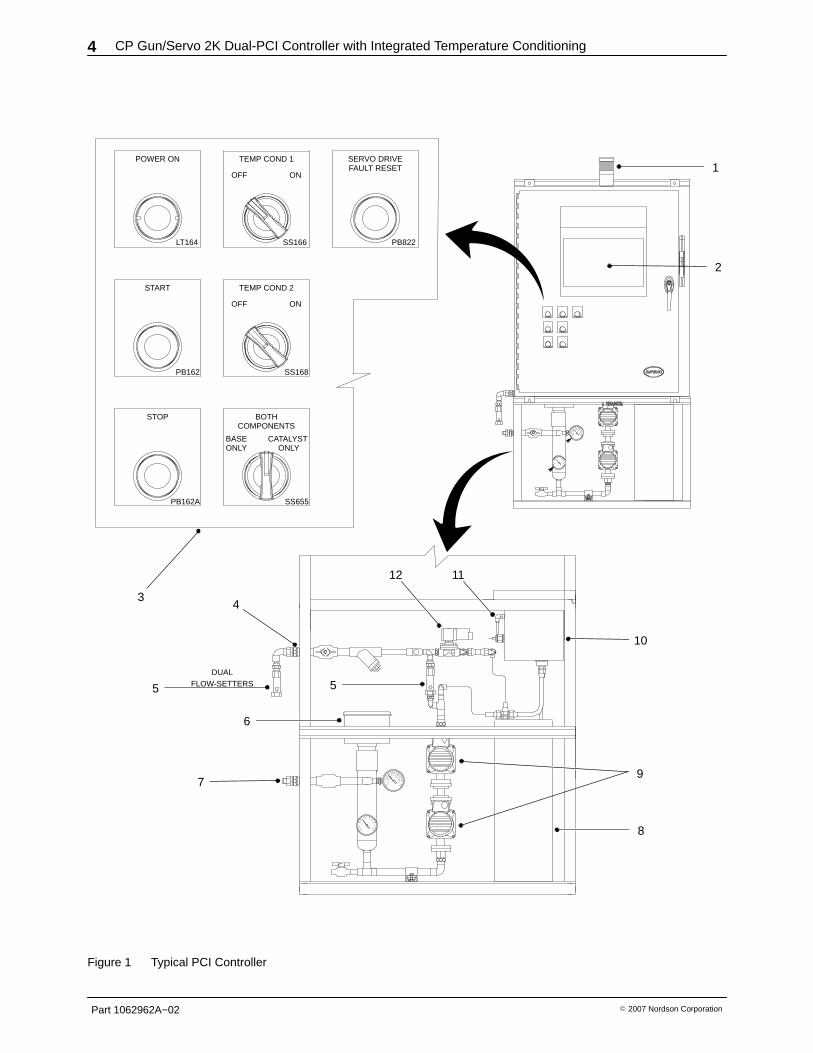
See Figure 1 and refer to Table 1 for a description of themajor components.
Theory of OperationThe robot controller sends a 0 to 10 volt DC analogsignal that is proportional to the speed of the robot. Thisvoltage can be a 12-bit word in the case of DeviceNet I/Osystems, or a single-ended voltage in a discrete I/Osystem. This voltage controls material flow rate throughthe CP Gun and Servo 2K Meter.
A bead size adjustment is provided to allow globalincrease or decrease of the amount of the robot analogsignal sent to the servomotor or CP Gun, giving theoperator the ability to increase or decrease the amount ofmaterial dispensed without the need to change the robotprogram.
If the air swirl option is used, a second analog signal fromthe robot passes through the controller to a proportioningair regulator. The proportioning air regulator controls theamount of swirl air flowing to the nozzle.
Temperature Conditioning
The temperature conditioning system in the PCIcontroller maintains temperature based on feedback froman RTD in the material stream, typically in a coaxialmaterial hose.
Temperature is maintained by heating or chilling thewater that is circulated throughout the system.Temperature setpoint and out-of-range limits are useradjustable. If the process temperature goes outside ofthis limit, a fault is posted, along with on-screen helpinformation for use in troubleshooting.
The heating element features an adjustableovertemperature thermostat that will disable power to theheater if the temperature of the water exceeds afactory-set limit.
Alarms
The PCI controller alerts the operator when a fault occursby lighting the alarm tower. The fault screen on theoperator interface provides a description of the fault, theappropriate corrective action to take, and how to contactNordson Corporation for assistance. A fault log screendisplays a list of faults.
CP Gun/Servo 2K Dual-PCI Controller with Integrated Temperature Conditioning4
Part 1062962A−02 � 2007 Nordson Corporation
2
1
3
ONLYONLYCATALYST
COMPONENTS
SS655
BASE
BOTH
SERVO DRIVEFAULT RESET
PB822
ONOFF
TEMP COND 1POWER ON
SS166
ONOFF
TEMP COND 2
LT164
START
SS168PB162
STOP
PB162A
PB162
LT161ALT161
CENTERLINEENCL DOOR
LC CENTERLINEENCL DOOR
LC
LT161A
PB162
PB162
LT161A
6
9
10
8
5
4
7
1112
5
DUALFLOW-SETTERS
Figure 1 Typical PCI Controller
CP Gun/Servo 2K Dual-PCI Controller with Integrated Temperature Conditioning 5
Part 1062962A−02� 2007 Nordson Corporation
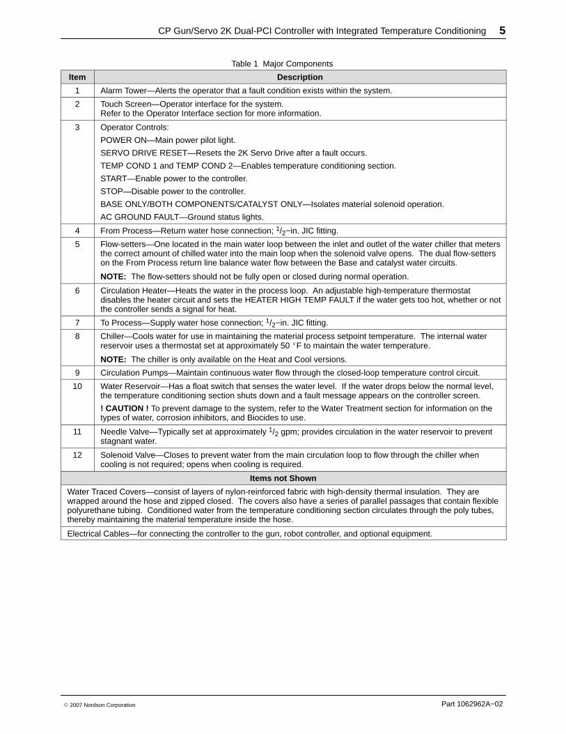
Table 1 Major Components
Item Description
1 Alarm Tower—Alerts the operator that a fault condition exists within the system.
2 Touch Screen—Operator interface for the system.Refer to the Operator Interface section for more information.
3 Operator Controls:
POWER ON—Main power pilot light.
SERVO DRIVE RESET—Resets the 2K Servo Drive after a fault occurs.
TEMP COND 1 and TEMP COND 2—Enables temperature conditioning section.
START—Enable power to the controller.
STOP—Disable power to the controller.
BASE ONLY/BOTH COMPONENTS/CATALYST ONLY—Isolates material solenoid operation.
AC GROUND FAULT—Ground status lights.
4 From Process—Return water hose connection; 1/2−in. JIC fitting.
5 Flow-setters—One located in the main water loop between the inlet and outlet of the water chiller that metersthe correct amount of chilled water into the main loop when the solenoid valve opens. The dual flow-setterson the From Process return line balance water flow between the Base and catalyst water circuits.
NOTE: The flow-setters should not be fully open or closed during normal operation.
6 Circulation Heater—Heats the water in the process loop. An adjustable high-temperature thermostatdisables the heater circuit and sets the HEATER HIGH TEMP FAULT if the water gets too hot, whether or notthe controller sends a signal for heat.
7 To Process—Supply water hose connection; 1/2−in. JIC fitting.
8 Chiller—Cools water for use in maintaining the material process setpoint temperature. The internal waterreservoir uses a thermostat set at approximately 50 �F to maintain the water temperature.
NOTE: The chiller is only available on the Heat and Cool versions.
9 Circulation Pumps—Maintain continuous water flow through the closed-loop temperature control circuit.
10 Water Reservoir—Has a float switch that senses the water level. If the water drops below the normal level,the temperature conditioning section shuts down and a fault message appears on the controller screen.
! CAUTION ! To prevent damage to the system, refer to the Water Treatment section for information on thetypes of water, corrosion inhibitors, and Biocides to use.
11 Needle Valve—Typically set at approximately 1/2 gpm; provides circulation in the water reservoir to preventstagnant water.
12 Solenoid Valve—Closes to prevent water from the main circulation loop to flow through the chiller whencooling is not required; opens when cooling is required.
Items not Shown
Water Traced Covers—consist of layers of nylon-reinforced fabric with high-density thermal insulation. They arewrapped around the hose and zipped closed. The covers also have a series of parallel passages that contain flexiblepolyurethane tubing. Conditioned water from the temperature conditioning section circulates through the poly tubes,thereby maintaining the material temperature inside the hose.
Electrical Cables—for connecting the controller to the gun, robot controller, and optional equipment.
CP Gun/Servo 2K Dual-PCI Controller with Integrated Temperature Conditioning6
Part 1062962A--02 E 2007 Nordson Corporation
Water TreatmentThe temperature conditioning section is constructed ofthe following materials. Always refer to this list if differentwater, corrosion inhibitors or biocides other than thoselisted in the following sections are used.
Black Iron Pipe Stainless steel Nylon
Brass PVC Plastic Copper
Buna Rubber Aluminum Polyurethane
Steel EPDM Rubber PTFE
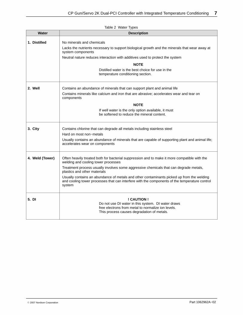
Water Types
Refer to Table 2. To minimize the introduction ofcontaminants that may degrade system components,review these guidelines before selecting the type ofwater to use.
NOTEWater types are listed in order of preference.
Corrosion Levels
To maintain proper performance, minimum levels ofcorrosion to aluminum and copper must be maintained.To maintain safe operation keep the corrosion levels of
S aluminum at or below 3 mil/year (0.003 in./yr).
S copper at or below 1 mil/year (0.001 in./yr).
When adding water to the system, corrosion inhibitormust be added. CorrShield MD405 corrosion inhibitor isshipped with the PCI controller. This is aMolybdate-based corrosion inhibitor that contains anAzole additive to protect copper and is used in theconcentration of 1.5 ounces per gallon of water tomaintain a concentration of 250--350 ppm.
The Ford Tox number for CorrShield MD 405 is 149163
The GM FID number for CorrShield MD 405 is 225484
Refer to the Parts section to order CorrShield MD 405.
Biocide Water Treatment
Do not use the following Biocides:
S oxidizers, such as chlorine, bromine, hydrogenperoxide, iodine, ozone, etc.
S cationic, or positively charged biocides.
Biocides for use with CorrShield MD405 areBetzDearborn Spectrus NX114. The recommendedconcentration of Spectrus NX114 is 150--PPM which is0.017 oz./gal (0.5 ml/gal).
The Ford Tox Number for Spectrus NX114 is 148270.
CP Gun/Servo 2K Dual-PCI Controller with Integrated Temperature Conditioning 7
Part 1062962A−02� 2007 Nordson Corporation
Table 2 Water Types
Water Description
1. Distilled No minerals and chemicals
Lacks the nutrients necessary to support biological growth and the minerals that wear away atsystem components
Neutral nature reduces interaction with additives used to protect the system
NOTEDistilled water is the best choice for use in thetemperature conditioning section.
2. Well Contains an abundance of minerals that can support plant and animal life
Contains minerals like calcium and iron that are abrasive; accelerates wear and tear oncomponents
NOTEIf well water is the only option available, it mustbe softened to reduce the mineral content.
3. City Contains chlorine that can degrade all metals including stainless steel
Hard on most non−metals
Usually contains an abundance of minerals that are capable of supporting plant and animal life;accelerates wear on components
4. Weld (Tower) Often heavily treated both for bacterial suppression and to make it more compatible with thewelding and cooling tower processes
Treatment process usually involves some aggressive chemicals that can degrade metals,plastics and other materials
Usually contains an abundance of metals and other contaminants picked up from the weldingand cooling tower processes that can interfere with the components of the temperature controlsystem
5. DI ! CAUTION !Do not use DI water in this system. DI water drawsfree electrons from metal to normalize ion levels.This process causes degradation of metals.
CP Gun/Servo 2K Dual-PCI Controller with Integrated Temperature Conditioning8
Part 1062962A−02 � 2007 Nordson Corporation
Installation
WARNING
� Allow only qualified personnel to perform thefollowing tasks. Follow the safety instructions inthis document and all other relateddocumentation.
� The robot controller contains electrical potentialsthat can be fatal. Disconnect and lock outelectrical power before making connections.
1. Unpack the PCI controller and inspect it for dents,scratches, corrosion, or other physical damage. Ifthere is any visible damage, call your NordsonCorporation representative immediately.
2. Install the controller as close to the robot controlleras possible.
GuidelinesReview the following guidelines:
� Hard-wire the controller to a dedicated power supplyto provide safe operation and reduce interferencefrom electrical noise.
� Install all electrical connections to local code.
� Install a locking disconnect switch or breaker in theservice line ahead of any electrical equipment.
� Electrical, fluid, and air connections are dependentupon application requirements. Use the SystemLayout and Interconnect drawings provided with thesystem documentation for all connections.
� Make sure that there is enough slack in all hose andcable routings to allow for proper system operation.
Configure the Robot ControllerUse the following data to configure the robot controlleranalog signals.
Analog #1
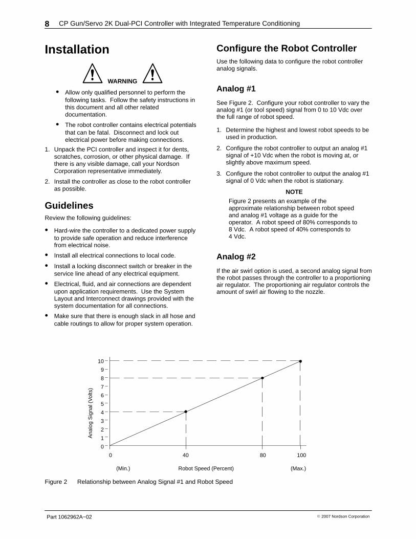
See Figure 2. Configure your robot controller to vary theanalog #1 (or tool speed) signal from 0 to 10 Vdc overthe full range of robot speed.
1. Determine the highest and lowest robot speeds to beused in production.
2. Configure the robot controller to output an analog #1signal of +10 Vdc when the robot is moving at, orslightly above maximum speed.
3. Configure the robot controller to output the analog #1signal of 0 Vdc when the robot is stationary.
NOTEFigure 2 presents an example of theapproximate relationship between robot speedand analog #1 voltage as a guide for theoperator. A robot speed of 80% corresponds to8 Vdc. A robot speed of 40% corresponds to4 Vdc.
Analog #2
If the air swirl option is used, a second analog signal fromthe robot passes through the controller to a proportioningair regulator. The proportioning air regulator controls theamount of swirl air flowing to the nozzle.
10
9
8
7
6
5
4
3
2
1
0
0 40 80 100
(Min.) (Max.)
Ana
log
Sig
nal (
Vol
ts)
Robot Speed (Percent)
Figure 2 Relationship between Analog Signal #1 and Robot Speed
CP Gun/Servo 2K Dual-PCI Controller with Integrated Temperature Conditioning 9
Part 1062962A−02� 2007 Nordson Corporation
Set Servo 2K Timing Sequences
There are two Servo 2K signal sequence configurations;RS4 and Non-RS4. Review the applicable paragraph forthe desired signal sequence.
Servo 2K RS4 Signal Sequence
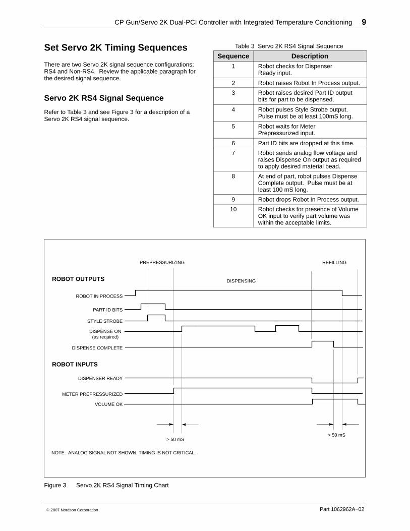
Refer to Table 3 and see Figure 3 for a description of aServo 2K RS4 signal sequence.
Table 3 Servo 2K RS4 Signal Sequence
Sequence Description1 Robot checks for Dispenser
Ready input.
2 Robot raises Robot In Process output.
3 Robot raises desired Part ID outputbits for part to be dispensed.
4 Robot pulses Style Strobe output.Pulse must be at least 100mS long.
5 Robot waits for MeterPrepressurized input.
6 Part ID bits are dropped at this time.
7 Robot sends analog flow voltage andraises Dispense On output as requiredto apply desired material bead.
8 At end of part, robot pulses DispenseComplete output. Pulse must be atleast 100 mS long.
9 Robot drops Robot In Process output.
10 Robot checks for presence of VolumeOK input to verify part volume waswithin the acceptable limits.
ROBOT IN PROCESS
ROBOT OUTPUTS
ROBOT INPUTS
NOTE: ANALOG SIGNAL NOT SHOWN; TIMING IS NOT CRITICAL.
PREPRESSURIZING
DISPENSING
REFILLING
PART ID BITS
STYLE STROBE
DISPENSE ON(as required)
DISPENSE COMPLETE
DISPENSER READY
METER PREPRESSURIZED
VOLUME OK
> 50 mS> 50 mS
Figure 3 Servo 2K RS4 Signal Timing Chart
CP Gun/Servo 2K Dual-PCI Controller with Integrated Temperature Conditioning10
Part 1062962A−02 � 2007 Nordson Corporation
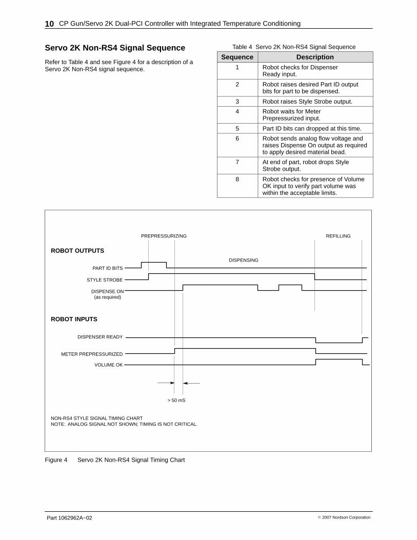
Servo 2K Non-RS4 Signal Sequence
Refer to Table 4 and see Figure 4 for a description of aServo 2K Non-RS4 signal sequence.
Table 4 Servo 2K Non-RS4 Signal Sequence
Sequence Description1 Robot checks for Dispenser
Ready input.
2 Robot raises desired Part ID outputbits for part to be dispensed.
3 Robot raises Style Strobe output.
4 Robot waits for MeterPrepressurized input.
5 Part ID bits can dropped at this time.
6 Robot sends analog flow voltage andraises Dispense On output as requiredto apply desired material bead.
7 At end of part, robot drops StyleStrobe output.
8 Robot checks for presence of VolumeOK input to verify part volume waswithin the acceptable limits.
NON-RS4 STYLE SIGNAL TIMING CHARTNOTE: ANALOG SIGNAL NOT SHOWN; TIMING IS NOT CRITICAL.
PREPRESSURIZING
DISPENSING
REFILLING
PART ID BITS
STYLE STROBE
DISPENSE ON(as required)
DISPENSER READY
METER PREPRESSURIZED
VOLUME OK
> 50 mS
ROBOT OUTPUTS
ROBOT INPUTS
Figure 4 Servo 2K Non-RS4 Signal Timing Chart
CP Gun/Servo 2K Dual-PCI Controller with Integrated Temperature Conditioning 11
Part 1062962A−02� 2007 Nordson Corporation
Servo 2K Auto-Purge Feature To prevent curing of the two−component material in themixer tube, the PCI controller features an Auto−Purgetimer.
The Time to Start Auto-Purge parameter and the durationof the purge are programmable in the hidden servicemenu. The auto-purge timer is reset by each dispensecycle. If the timer reaches the programmed value, thecontroller raises Purge Request output to the robot. Therobot responds by raising Clear to Purge input to thedispense controller. This indicates that the robot is in asafe position to perform the purge. At this point, thecontroller executes an auto-purge for the programmedduration.
If the robot does not respond with the Clear to Purgesignal, a Mixer Tube Timeout fault appears on the displaywhen the programmed time value is reached.
Servo 2K Prepressure Setpoints To optimize the start of the dispensed bead, thePrepressure Setpoint parameter is entered in the Servo2K Setup menu. This menu is hidden in the ServiceMenu to limit access.
The values entered for base and catalyst prepressureshould be close to the dynamic values seen duringdispensing of the part.
When the style strobe is received, the ball screws willbegin moving forward until the first prepressure valueentered for the current Part ID is reached. This can beeither the base or catalyst pressure depending upon thevalues entered and material characteristics. At this point,the ball screws will stop and the Meter Prepressurizedsignal is sent to the robot, indicating that dispensing canbegin.
If the dispense meter has the optional stitching refillvalves, unloader pressure raises the pressure of thecylinder that did not reach its setpoint when themotor stopped.
CP Gun/Servo 2K Dual-PCI Controller with Integrated Temperature Conditioning12
Part 1062962A−02 � 2007 Nordson Corporation
Set CP Gun Timing Sequences
There are two CP Gun signal sequence configurations;RS4 and Non-RS4. Review the applicable paragraph forthe desired signal sequence.
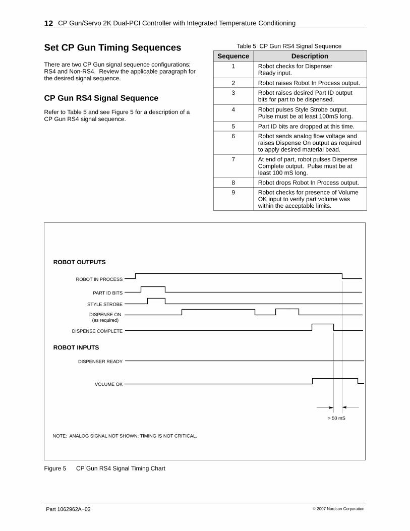
CP Gun RS4 Signal Sequence
Refer to Table 5 and see Figure 5 for a description of aCP Gun RS4 signal sequence.
Table 5 CP Gun RS4 Signal Sequence
Sequence Description1 Robot checks for Dispenser
Ready input.
2 Robot raises Robot In Process output.
3 Robot raises desired Part ID outputbits for part to be dispensed.
4 Robot pulses Style Strobe output.Pulse must be at least 100mS long.
5 Part ID bits are dropped at this time.
6 Robot sends analog flow voltage andraises Dispense On output as requiredto apply desired material bead.
7 At end of part, robot pulses DispenseComplete output. Pulse must be atleast 100 mS long.
8 Robot drops Robot In Process output.
9 Robot checks for presence of VolumeOK input to verify part volume waswithin the acceptable limits.
ROBOT IN PROCESS
ROBOT OUTPUTS
ROBOT INPUTS
NOTE: ANALOG SIGNAL NOT SHOWN; TIMING IS NOT CRITICAL.
PART ID BITS
STYLE STROBE
DISPENSE ON(as required)
DISPENSE COMPLETE
DISPENSER READY
VOLUME OK
> 50 mS
Figure 5 CP Gun RS4 Signal Timing Chart
CP Gun/Servo 2K Dual-PCI Controller with Integrated Temperature Conditioning 13
Part 1062962A−02� 2007 Nordson Corporation
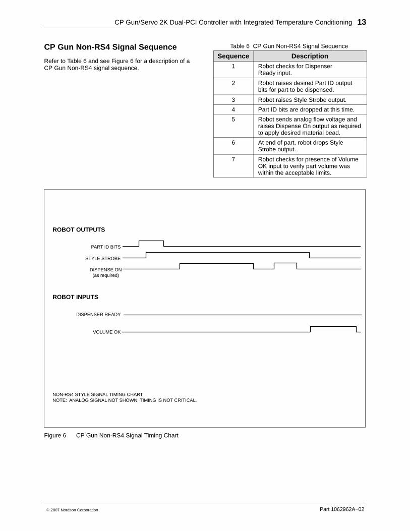
CP Gun Non-RS4 Signal Sequence
Refer to Table 6 and see Figure 6 for a description of aCP Gun Non-RS4 signal sequence.
Table 6 CP Gun Non-RS4 Signal Sequence
Sequence Description1 Robot checks for Dispenser
Ready input.
2 Robot raises desired Part ID outputbits for part to be dispensed.
3 Robot raises Style Strobe output.
4 Part ID bits are dropped at this time.
5 Robot sends analog flow voltage andraises Dispense On output as requiredto apply desired material bead.
6 At end of part, robot drops StyleStrobe output.
7 Robot checks for presence of VolumeOK input to verify part volume waswithin the acceptable limits.
NON-RS4 STYLE SIGNAL TIMING CHARTNOTE: ANALOG SIGNAL NOT SHOWN; TIMING IS NOT CRITICAL.
PART ID BITS
STYLE STROBE
DISPENSE ON(as required)
DISPENSER READY
VOLUME OK
ROBOT OUTPUTS
ROBOT INPUTS
Figure 6 CP Gun Non-RS4 Signal Timing Chart
CP Gun/Servo 2K Dual-PCI Controller with Integrated Temperature Conditioning14
Part 1062962A−02 � 2007 Nordson Corporation
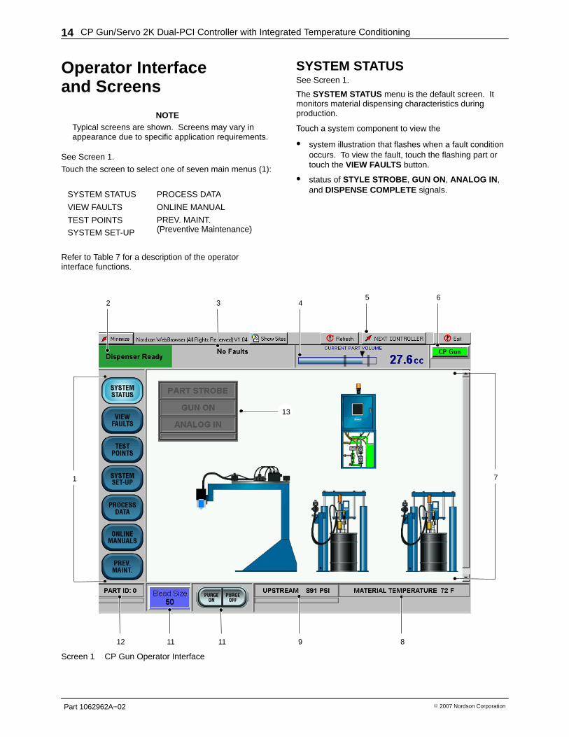
Operator Interfaceand Screens
NOTETypical screens are shown. Screens may vary inappearance due to specific application requirements.
See Screen 1.
Touch the screen to select one of seven main menus (1):
SYSTEM STATUS PROCESS DATA
VIEW FAULTS ONLINE MANUAL
TEST POINTS PREV. MAINT.(Preventive Maintenance)SYSTEM SET-UP
PREV. MAINT.(Preventive Maintenance)
Refer to Table 7 for a description of the operatorinterface functions.
SYSTEM STATUSSee Screen 1.
The SYSTEM STATUS menu is the default screen. Itmonitors material dispensing characteristics duringproduction.
Touch a system component to view the
� system illustration that flashes when a fault conditionoccurs. To view the fault, touch the flashing part ortouch the VIEW FAULTS button.
� status of STYLE STROBE , GUN ON, ANALOG IN ,and DISPENSE COMPLETE signals.
2 436
1 7
12 11 9 8
5
11
13
Screen 1 CP Gun Operator Interface
CP Gun/Servo 2K Dual-PCI Controller with Integrated Temperature Conditioning 15
Part 1062962A−02� 2007 Nordson Corporation
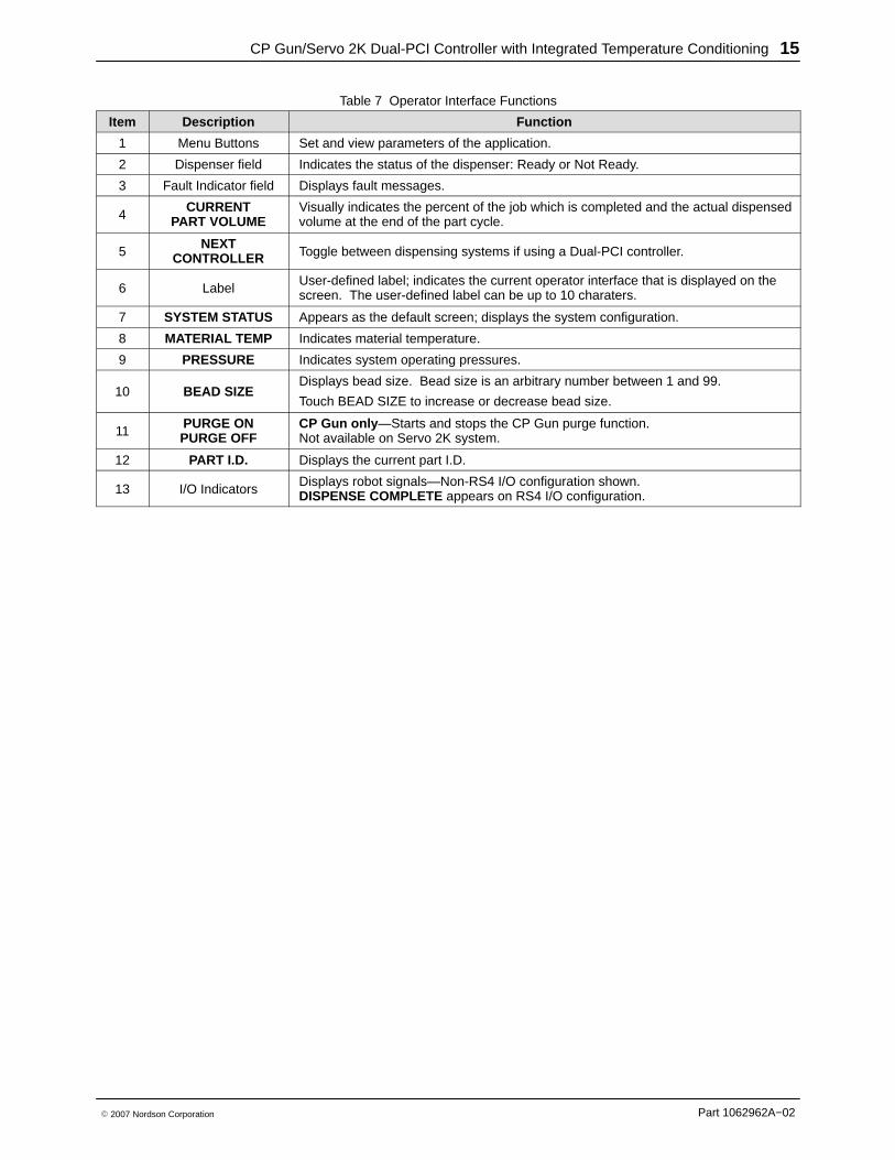
Table 7 Operator Interface Functions
Item Description Function
1 Menu Buttons Set and view parameters of the application.
2 Dispenser field Indicates the status of the dispenser: Ready or Not Ready.
3 Fault Indicator field Displays fault messages.
4CURRENT
PART VOLUMEVisually indicates the percent of the job which is completed and the actual dispensedvolume at the end of the part cycle.
5NEXT
CONTROLLER Toggle between dispensing systems if using a Dual-PCI controller.
6 LabelUser-defined label; indicates the current operator interface that is displayed on thescreen. The user-defined label can be up to 10 charaters.
7 SYSTEM STATUS Appears as the default screen; displays the system configuration.
8 MATERIAL TEMP Indicates material temperature.
9 PRESSURE Indicates system operating pressures.
10 BEAD SIZEDisplays bead size. Bead size is an arbitrary number between 1 and 99.
Touch BEAD SIZE to increase or decrease bead size.
11PURGE ONPURGE OFF
CP Gun only —Starts and stops the CP Gun purge function.Not available on Servo 2K system.
12 PART I.D. Displays the current part I.D.
13 I/O IndicatorsDisplays robot signals—Non-RS4 I/O configuration shown.DISPENSE COMPLETE appears on RS4 I/O configuration.
CP Gun/Servo 2K Dual-PCI Controller with Integrated Temperature Conditioning16
Part 1062962A−02 � 2007 Nordson Corporation
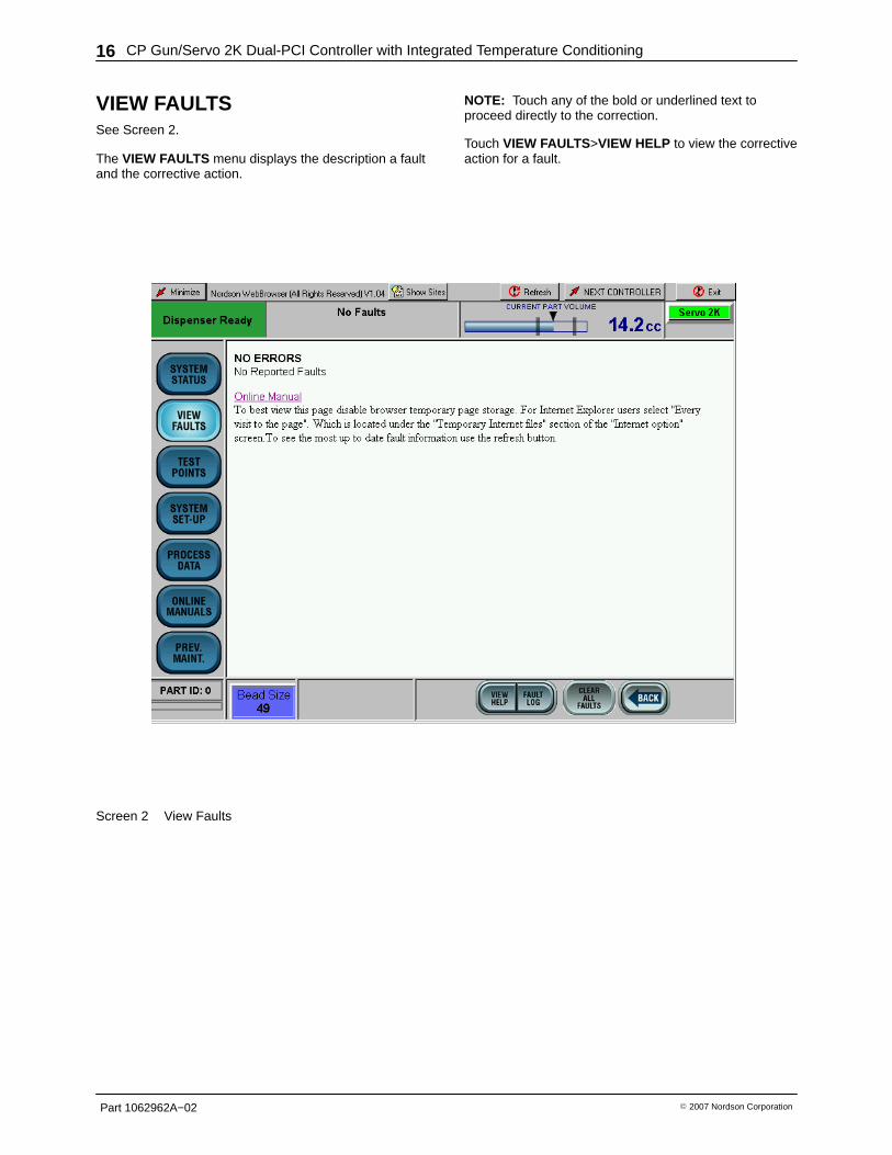
VIEW FAULTSSee Screen 2.
The VIEW FAULTS menu displays the description a faultand the corrective action.
NOTE: Touch any of the bold or underlined text toproceed directly to the correction.
Touch VIEW FAULTS>VIEW HELP to view the correctiveaction for a fault.
Screen 2 View Faults
CP Gun/Servo 2K Dual-PCI Controller with Integrated Temperature Conditioning 17
Part 1062962A−02� 2007 Nordson Corporation
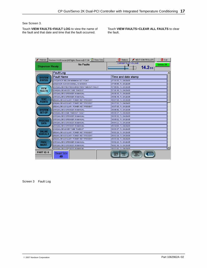
See Screen 3.
Touch VIEW FAULTS>FAULT LOG to view the name ofthe fault and that date and time that the fault occurred.
Touch VIEW FAULTS>CLEAR ALL FAULTS to clearthe fault.
Screen 3 Fault Log
CP Gun/Servo 2K Dual-PCI Controller with Integrated Temperature Conditioning18
Part 1062962A−02 � 2007 Nordson Corporation
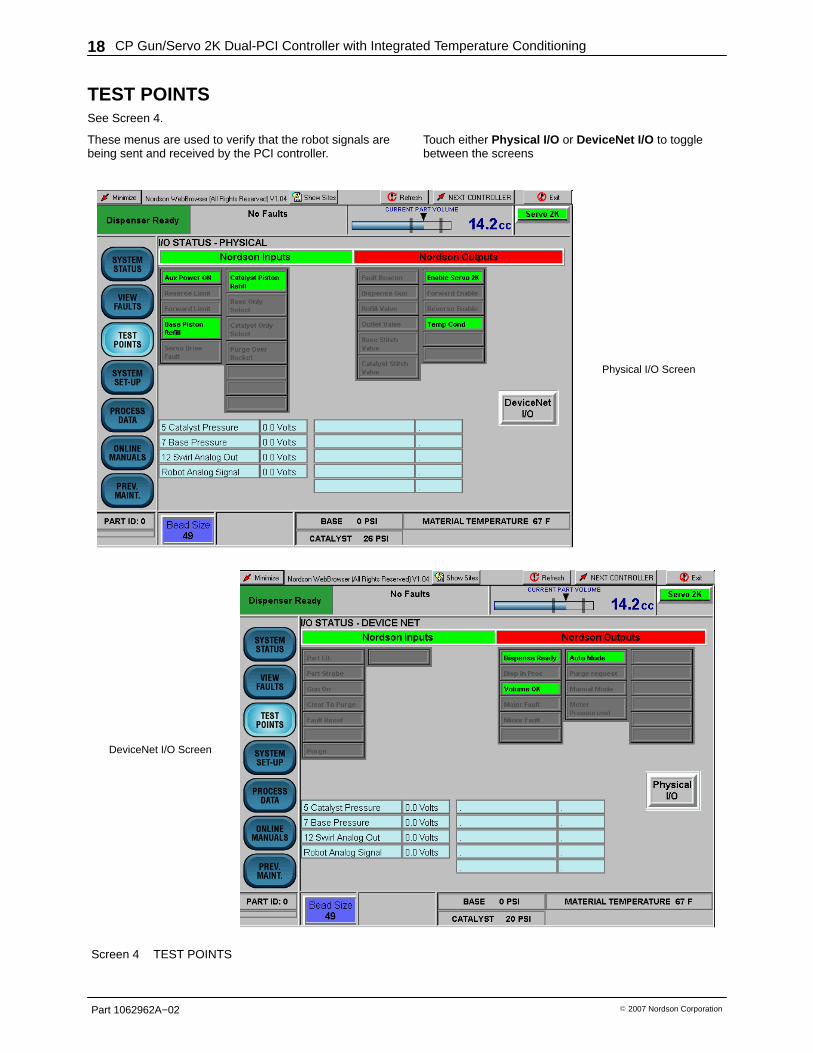
TEST POINTSSee Screen 4.
These menus are used to verify that the robot signals arebeing sent and received by the PCI controller.
Touch either Physical I/O or DeviceNet I/O to togglebetween the screens
Physical I/O Screen
DeviceNet I/O Screen
Screen 4 TEST POINTS
CP Gun/Servo 2K Dual-PCI Controller with Integrated Temperature Conditioning 19
Part 1062962A−02� 2007 Nordson Corporation
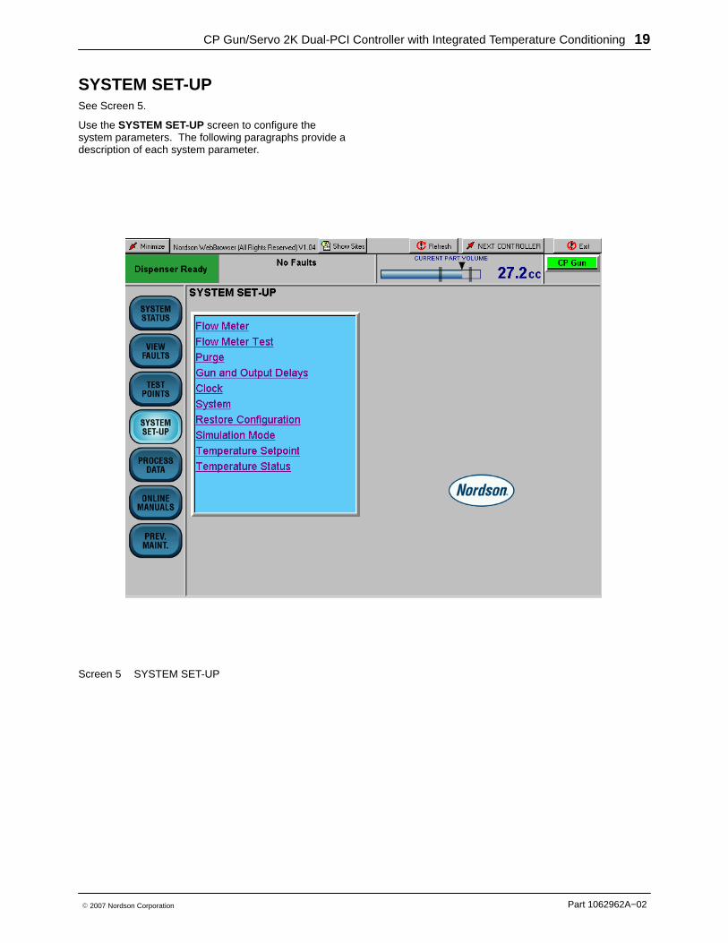
SYSTEM SET-UPSee Screen 5.
Use the SYSTEM SET-UP screen to configure thesystem parameters. The following paragraphs provide adescription of each system parameter.
Screen 5 SYSTEM SET-UP

CP Gun/Servo 2K Dual-PCI Controller with Integrated Temperature Conditioning20
Part 1062962A−02 � 2007 Nordson Corporation
Flow MeterSee Screen 6.
When a new flowmeter is installed, enter its flow rate(or K-value) in counts/liter. The K-value is stamped onthe side of the flowmeter body.
Touch the screen keyboard to enter counts/liter from1−100,000,000.
Screen 6 Flow Meter
CP Gun/Servo 2K Dual-PCI Controller with Integrated Temperature Conditioning 21
Part 1062962A−02� 2007 Nordson Corporation
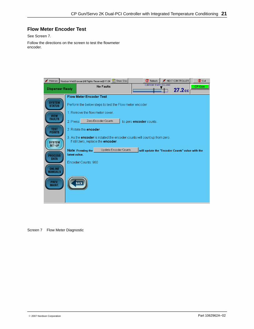
Flow Meter Encoder TestSee Screen 7.
Follow the directions on the screen to test the flowmeterencoder.
Screen 7 Flow Meter Diagnostic
CP Gun/Servo 2K Dual-PCI Controller with Integrated Temperature Conditioning22
Part 1062962A−02 � 2007 Nordson Corporation
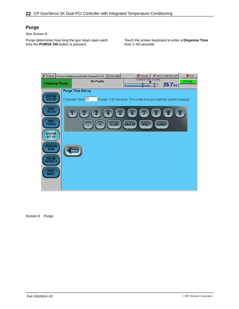
PurgeSee Screen 8.
Purge determines how long the gun stays open eachtime the PURGE ON button is pressed.
Touch the screen keyboard to enter a Dispense Timefrom 1−60 seconds.
Screen 8 Purge
CP Gun/Servo 2K Dual-PCI Controller with Integrated Temperature Conditioning 23
Part 1062962A−02� 2007 Nordson Corporation
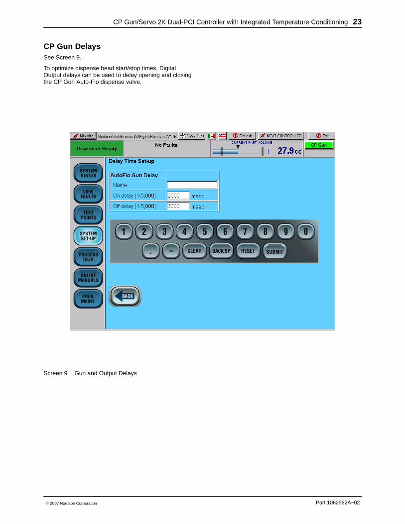
CP Gun DelaysSee Screen 9.
To optimize dispense bead start/stop times, DigitalOutput delays can be used to delay opening and closingthe CP Gun Auto-Flo dispense valve.
Screen 9 Gun and Output Delays
CP Gun/Servo 2K Dual-PCI Controller with Integrated Temperature Conditioning24
Part 1062962A−02 � 2007 Nordson Corporation
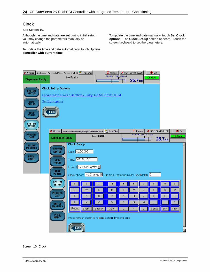
ClockSee Screen 10.
Although the time and date are set during initial setup,you may change the parameters manually orautomatically.
To update the time and date automatically, touch Updatecontroller with current time .
To update the time and date manually, touch Set Clockoptions . The Clock Set-up screen appears. Touch thescreen keyboard to set the parameters.
Screen 10 Clock

CP Gun/Servo 2K Dual-PCI Controller with Integrated Temperature Conditioning 25
Part 1062962A−02� 2007 Nordson Corporation
SystemSee Screen 11.
Touch the keyboard to select Metric or English systemunits; clock format; type of pressure unit; bead sizeglobal or by Part ID
Screen 11 System

CP Gun/Servo 2K Dual-PCI Controller with Integrated Temperature Conditioning26
Part 1062962A−02 � 2007 Nordson Corporation
Pump Stand 1
See Screen 12.
If a pump stand is used, touch Pump Stand 1 to view the status of the pump stand.
Touch Pressurize Pump Stand to pressurize the pump stand.
Touch Depressurize Pump Stand to depressurize the pump stand.
Screen 12 Pump Stand 1

CP Gun/Servo 2K Dual-PCI Controller with Integrated Temperature Conditioning 27
Part 1062962A−02� 2007 Nordson Corporation
Restore Configuration See Screen 13.
Use the drop-down menu to select a previously storedconfiguration.
Screen 13 Restore Configuration
CP Gun/Servo 2K Dual-PCI Controller with Integrated Temperature Conditioning28
Part 1062962A−02 � 2007 Nordson Corporation
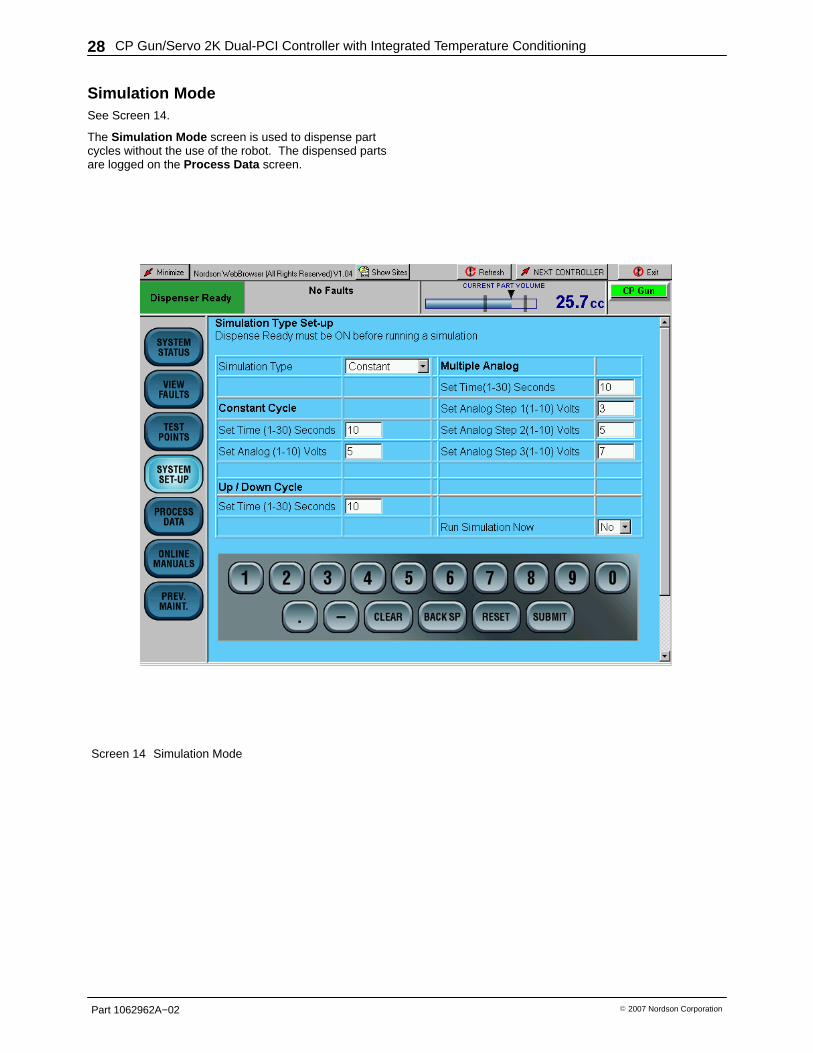
Simulation ModeSee Screen 14.
The Simulation Mode screen is used to dispense partcycles without the use of the robot. The dispensed partsare logged on the Process Data screen.
Screen 14 Simulation Mode
CP Gun/Servo 2K Dual-PCI Controller with Integrated Temperature Conditioning 29
Part 1062962A−02� 2007 Nordson Corporation
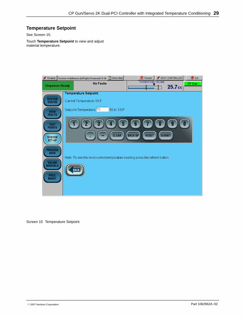
Temperature Setpoint See Screen 15.
Touch Temperature Setpoint to view and adjustmaterial temperature.
Screen 15 Temperature Setpoint
CP Gun/Servo 2K Dual-PCI Controller with Integrated Temperature Conditioning30
Part 1062962A−02 � 2007 Nordson Corporation
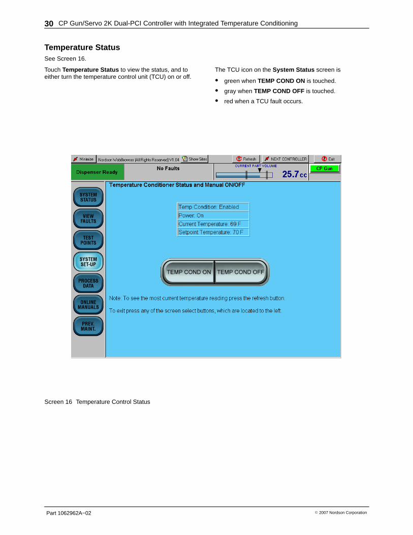
Temperature Status See Screen 16.
Touch Temperature Status to view the status, and toeither turn the temperature control unit (TCU) on or off.
The TCU icon on the System Status screen is
� green when TEMP COND ON is touched.
� gray when TEMP COND OFF is touched.
� red when a TCU fault occurs.
Screen 16 Temperature Control Status

CP Gun/Servo 2K Dual-PCI Controller with Integrated Temperature Conditioning 31
Part 1062962A−02� 2007 Nordson Corporation
Servo 2K SYSTEM SET-UP
See Screen 17.
Use the SYSTEM SET-UP screen to configure the Servo2K system parameters.
NOTE
The Servo 2K SYSTEM SET-UP screens areidentical to the CP Gun SYSTEM SET-UPscreens with the exception of the Servo 2KManual Mode screen. Refer to the followingparagraph for a description of this screen.
Screen 17 SYSTEM SET-UP
CP Gun/Servo 2K Dual-PCI Controller with Integrated Temperature Conditioning32
Part 1062962A−02 � 2007 Nordson Corporation
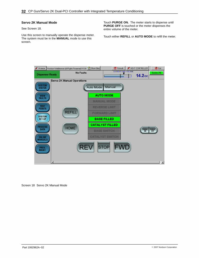
Servo 2K Manual Mode
See Screen 18.
Use this screen to manually operate the dispense meter.The system must be in the MANUAL mode to use thisscreen.
Touch PURGE ON. The meter starts to dispense untilPURGE OFF is touched or the meter dispenses theentire volume of the meter.
Touch either REFILL or AUTO MODE to refill the meter.
Screen 18 Servo 2K Manual Mode
CP Gun/Servo 2K Dual-PCI Controller with Integrated Temperature Conditioning 33
Part 1062962A−02� 2007 Nordson Corporation
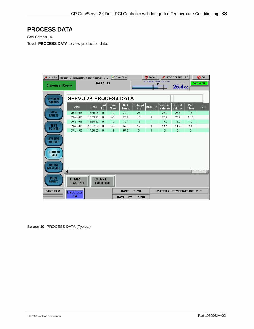
PROCESS DATASee Screen 19.
Touch PROCESS DATA to view production data.
Screen 19 PROCESS DATA (Typical)
CP Gun/Servo 2K Dual-PCI Controller with Integrated Temperature Conditioning34
Part 1062962A−02 � 2007 Nordson Corporation
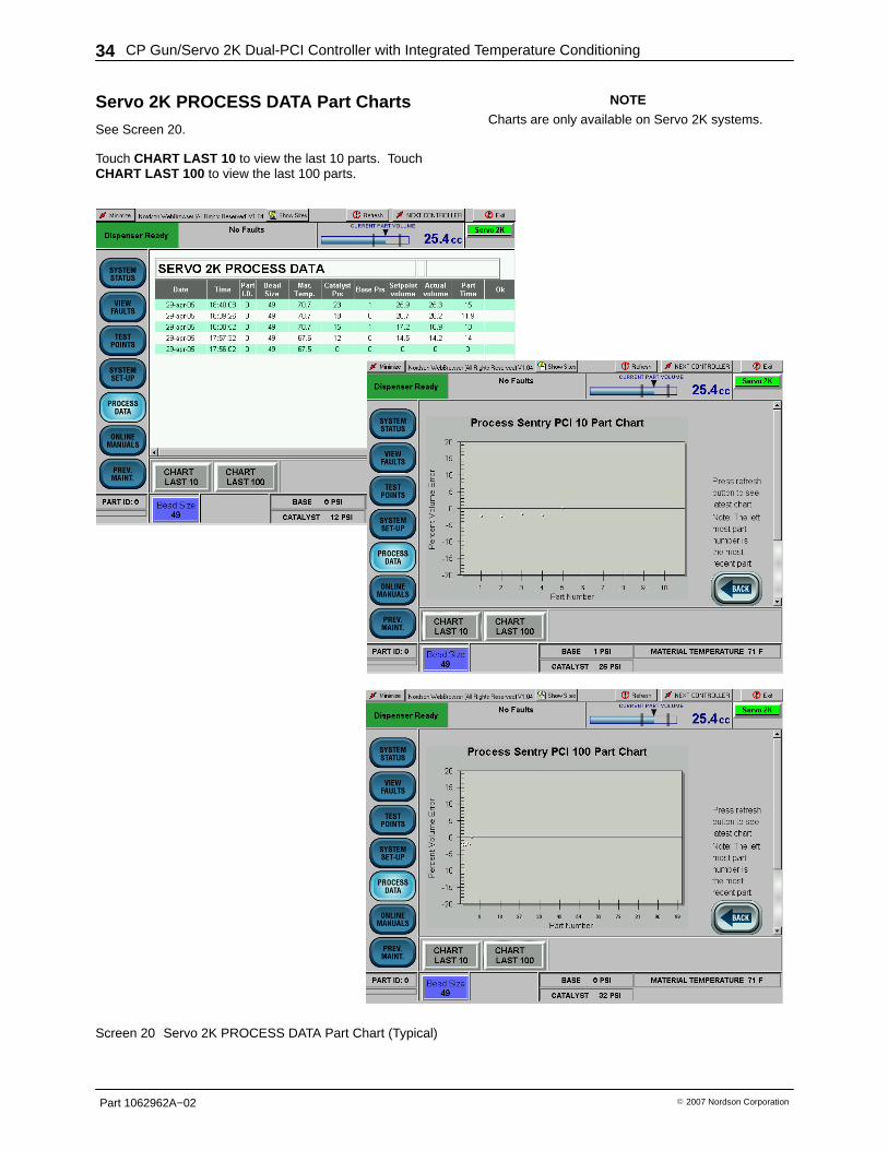
Servo 2K PROCESS DATA Part Charts
See Screen 20.
Touch CHART LAST 10 to view the last 10 parts. TouchCHART LAST 100 to view the last 100 parts.
NOTE
Charts are only available on Servo 2K systems.
Screen 20 Servo 2K PROCESS DATA Part Chart (Typical)
CP Gun/Servo 2K Dual-PCI Controller with Integrated Temperature Conditioning 35
Part 1062962A−02� 2007 Nordson Corporation
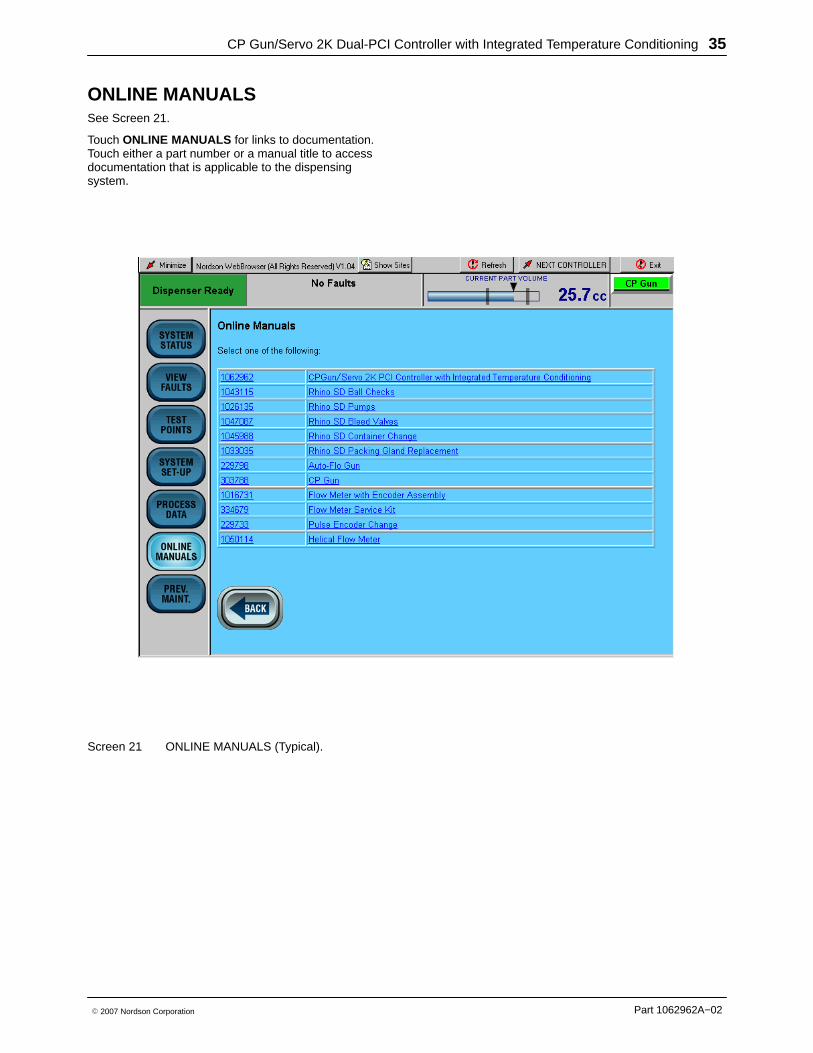
ONLINE MANUALSSee Screen 21.
Touch ONLINE MANUALS for links to documentation.Touch either a part number or a manual title to accessdocumentation that is applicable to the dispensingsystem.
Screen 21 ONLINE MANUALS (Typical).
CP Gun/Servo 2K Dual-PCI Controller with Integrated Temperature Conditioning36
Part 1062962A−02 � 2007 Nordson Corporation
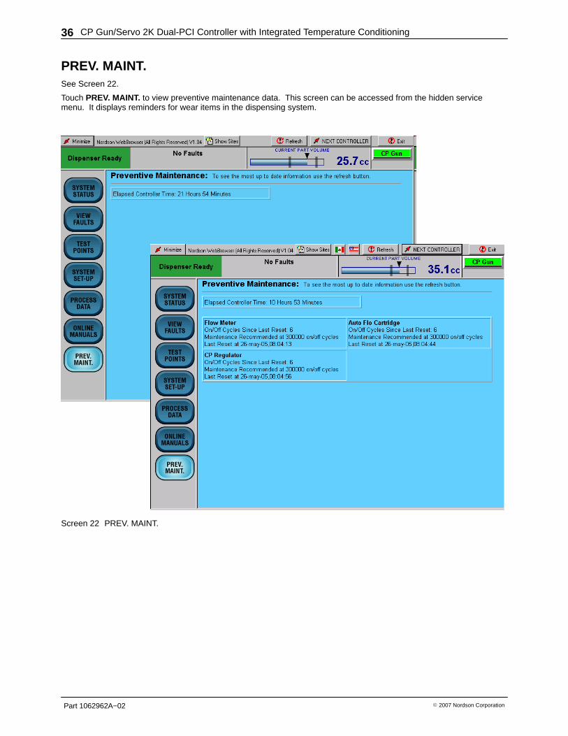
PREV. MAINT.See Screen 22.
Touch PREV. MAINT. to view preventive maintenance data. This screen can be accessed from the hidden servicemenu. It displays reminders for wear items in the dispensing system.
Screen 22 PREV. MAINT.
CP Gun/Servo 2K Dual-PCI Controller with Integrated Temperature Conditioning 37
Part 1062962A−02� 2007 Nordson Corporation
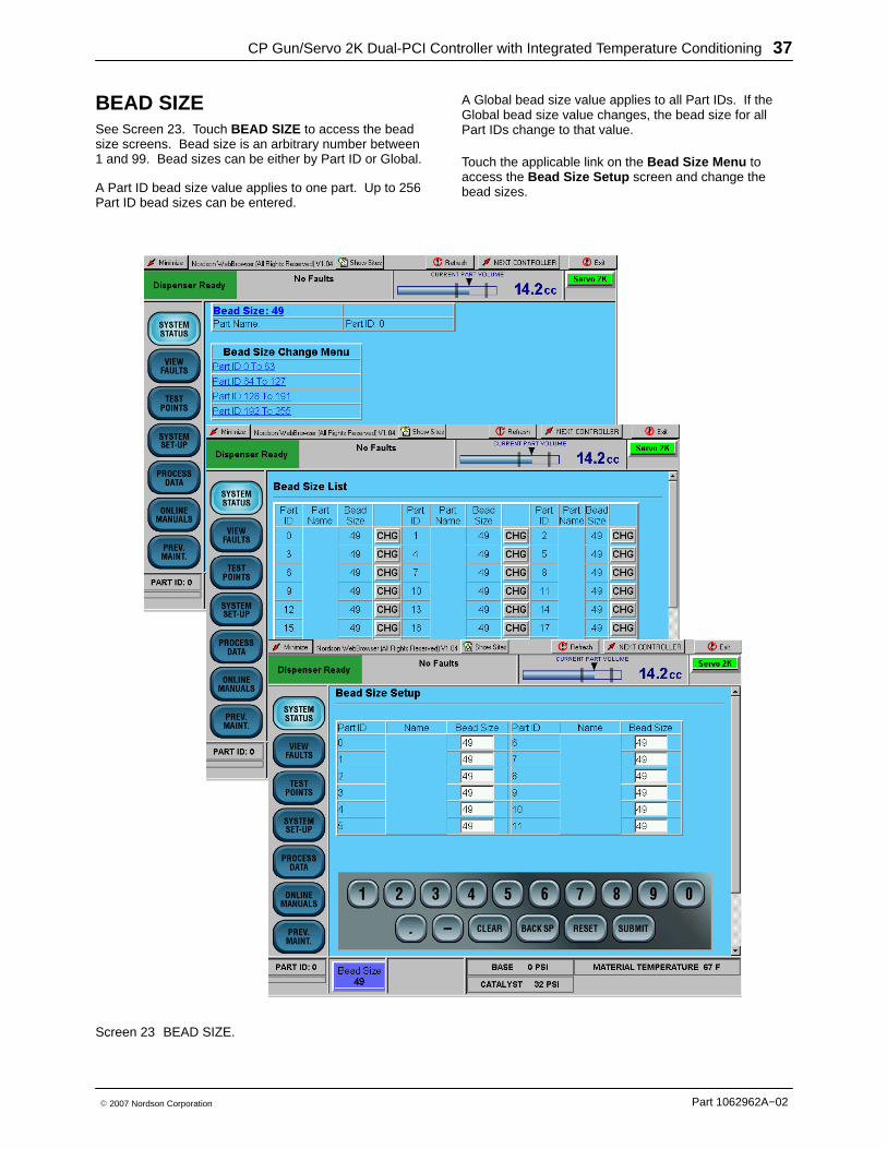
BEAD SIZESee Screen 23. Touch BEAD SIZE to access the beadsize screens. Bead size is an arbitrary number between1 and 99. Bead sizes can be either by Part ID or Global.
A Part ID bead size value applies to one part. Up to 256Part ID bead sizes can be entered.
A Global bead size value applies to all Part IDs. If theGlobal bead size value changes, the bead size for allPart IDs change to that value.
Touch the applicable link on the Bead Size Menu toaccess the Bead Size Setup screen and change thebead sizes.
Screen 23 BEAD SIZE.
CP Gun/Servo 2K Dual-PCI Controller with Integrated Temperature Conditioning38
Part 1062962A−02 � 2007 Nordson Corporation
Operation
WARNING
� Allow only qualified personnel to perform thefollowing tasks. Follow the safety instructions inthis document and all other relateddocumentation.
� Read and understand this section beforeoperating the PCI controller. The procedures inthis section assume that the PCI controller wasconfigured by a Nordson Corporationrepresentative.
NOTE
� Before operating the controller, make sure thateach robot is taught the proper tool path. Referto the robot controller manual for procedures.
� When entering data, touching the field next tothe corresponding parameter positions thecursor inside of the field.
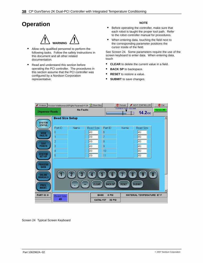
See Screen 24. Some parameters require the use of thescreen keyboard to enter data. When entering data,touch
� CLEAR to delete the current value in a field.
� BACK SP to backspace.
� RESET to restore a value.
� SUBMIT to save changes.
Screen 24 Typical Screen Keyboard
CP Gun/Servo 2K Dual-PCI Controller with Integrated Temperature Conditioning 39
Part 1062962A−02� 2007 Nordson Corporation
Start the TemperatureConditioning Unit
NOTEOnly perform this procedure for new PCIcontrollers that have not been used in production.
1. Flush the piping system with water, drain and refill.
2. Fill the water reservoir. Refer to the Fill the WaterReservoir procedure in this section.
3. Heat and Cool Versions Only —Turn off the chillerand heater circuit breakers.
4. Power up the PCI controller. Turn the TEMP CONDswitch(s) to ON.
5. From the Temperature Status screen, touchTEMP COND ON to enable the temperature controland water circulation loop. The system is nowcirculating water.
6. Check the pressure gauge for each circuit. Normaloperating pressure is between 22 to 28 psi. If thepressure is below 20 psi make sure all air is purgedfrom system and both pumps in the circuit areoperating.
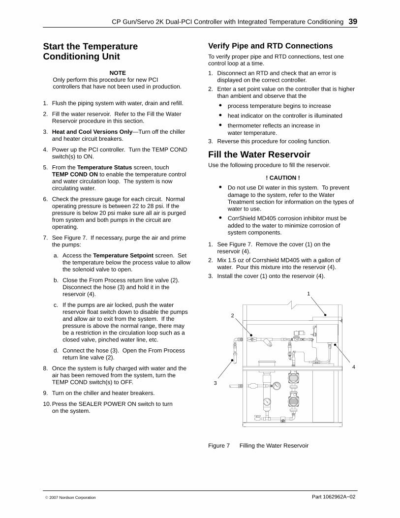
7. See Figure 7. If necessary, purge the air and primethe pumps:
a. Access the Temperature Setpoint screen. Setthe temperature below the process value to allowthe solenoid valve to open.
b. Close the From Process return line valve (2).Disconnect the hose (3) and hold it in thereservoir (4).
c. If the pumps are air locked, push the waterreservoir float switch down to disable the pumpsand allow air to exit from the system. If thepressure is above the normal range, there maybe a restriction in the circulation loop such as aclosed valve, pinched water line, etc.
d. Connect the hose (3). Open the From Processreturn line valve (2).
8. Once the system is fully charged with water and theair has been removed from the system, turn theTEMP COND switch(s) to OFF.
9. Turn on the chiller and heater breakers.
10. Press the SEALER POWER ON switch to turnon the system.
Verify Pipe and RTD Connections To verify proper pipe and RTD connections, test onecontrol loop at a time.
1. Disconnect an RTD and check that an error isdisplayed on the correct controller.
2. Enter a set point value on the controller that is higherthan ambient and observe that the
� process temperature begins to increase
� heat indicator on the controller is illuminated
� thermometer reflects an increase inwater temperature.
3. Reverse this procedure for cooling function.
Fill the Water Reservoir Use the following procedure to fill the reservoir.
! CAUTION !
� Do not use DI water in this system. To preventdamage to the system, refer to the WaterTreatment section for information on the types ofwater to use.
� CorrShield MD405 corrosion inhibitor must beadded to the water to minimize corrosion ofsystem components.
1. See Figure 7. Remove the cover (1) on thereservoir (4).
2. Mix 1.5 oz of Corrshield MD405 with a gallon ofwater. Pour this mixture into the reservoir (4).
3. Install the cover (1) onto the reservoir (4).
1
2
3
4
Figure 7 Filling the Water Reservoir
CP Gun/Servo 2K Dual-PCI Controller with Integrated Temperature Conditioning40
Part 1062962A−02 � 2007 Nordson Corporation
Start the Controller Use the following procedures to start the controller.
1. Turn on power to the controller.
2. After the system finishes the boot-up process, pressthe POWER ON button on the front of the cabinet.
3. Perform the CP Gun System and Servo 2K Systemprocedures in this section.
NOTEOperating procedures may vary due specificapplication requirements. Refer to your SystemParameter Sheet for specific operating settings.
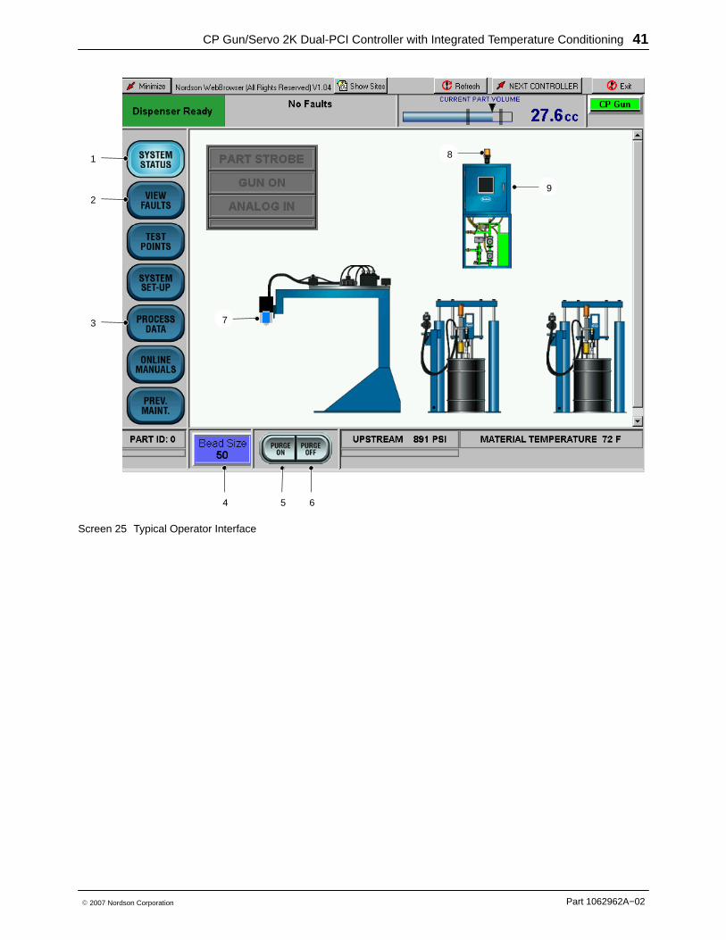
CP Gun System1. See Screen 25. Place a waste container under the
gun (7).
2. Verify that the pumps are at operating pressure.
3. Touch PURGE ON (5) to remove air from the materialsupply hose and nozzle.
4. Purging stops after the purge time has elapsed. Ifdesired, press PURGE OFF (6) to stop purgingimmediately.
5. Check the correct bead size used for the part beingrun. Touch BEAD SIZE (4) to make adjustments.
6. In the Bead Options fields, touch the keyboard tochange the values.
CP Gun/Servo 2K Dual-PCI Controller with Integrated Temperature Conditioning 41
Part 1062962A−02� 2007 Nordson Corporation
2
1
4 5 6
7
8
3
9
Screen 25 Typical Operator Interface
CP Gun/Servo 2K Dual-PCI Controller with Integrated Temperature Conditioning42
Part 1062962A−02 � 2007 Nordson Corporation
Servo 2K System
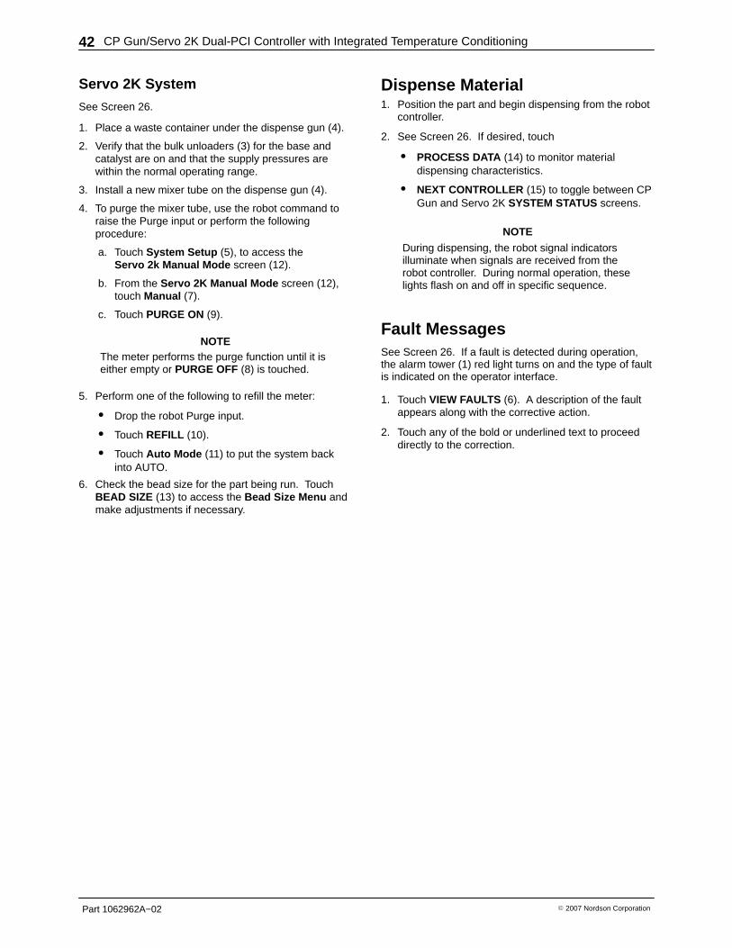
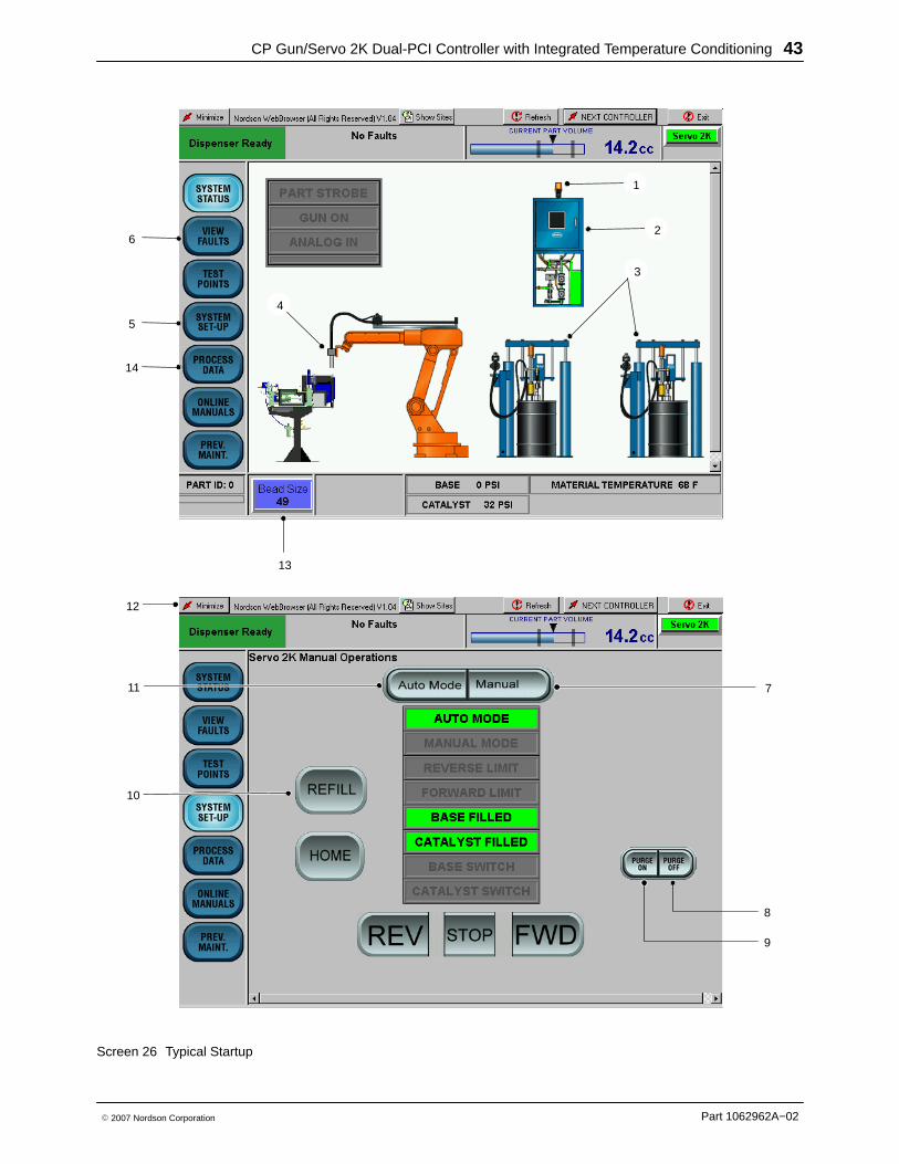
See Screen 26.
1. Place a waste container under the dispense gun (4).
2. Verify that the bulk unloaders (3) for the base andcatalyst are on and that the supply pressures arewithin the normal operating range.
3. Install a new mixer tube on the dispense gun (4).
4. To purge the mixer tube, use the robot command toraise the Purge input or perform the followingprocedure:
a. Touch System Setup (5), to access theServo 2k Manual Mode screen (12).
b. From the Servo 2K Manual Mode screen (12),touch Manual (7).
c. Touch PURGE ON (9).
NOTEThe meter performs the purge function until it iseither empty or PURGE OFF (8) is touched.
5. Perform one of the following to refill the meter:
� Drop the robot Purge input.
� Touch REFILL (10).
� Touch Auto Mode (11) to put the system backinto AUTO.
6. Check the bead size for the part being run. TouchBEAD SIZE (13) to access the Bead Size Menu andmake adjustments if necessary.
Dispense Material 1. Position the part and begin dispensing from the robot
controller.
2. See Screen 26. If desired, touch
� PROCESS DATA (14) to monitor materialdispensing characteristics.
� NEXT CONTROLLER (15) to toggle between CPGun and Servo 2K SYSTEM STATUS screens.
NOTE
During dispensing, the robot signal indicatorsilluminate when signals are received from therobot controller. During normal operation, theselights flash on and off in specific sequence.
Fault MessagesSee Screen 26. If a fault is detected during operation,the alarm tower (1) red light turns on and the type of faultis indicated on the operator interface.
1. Touch VIEW FAULTS (6). A description of the faultappears along with the corrective action.
2. Touch any of the bold or underlined text to proceeddirectly to the correction.
CP Gun/Servo 2K Dual-PCI Controller with Integrated Temperature Conditioning 43
Part 1062962A−02� 2007 Nordson Corporation
5
2
4
3
10
8
1
6
11 7
9
12
13
14
Screen 26 Typical Startup

CP Gun/Servo 2K Dual-PCI Controller with Integrated Temperature Conditioning44
Part 1062962A−02 � 2007 Nordson Corporation
CP Gun Alarm Settings See Screen 27. The Alarm setup screen can only beaccessed through the hidden Service Menu.
Alarm trip points for low and high part volume andmaterial pressure are programmable by Part ID.
When the material pressure value falls outside of theprogrammable limits, a major fault appears on theVIEW FAULTS screen along with a Help message.
When dispensed volume is outside the programmablelimits, a major fault appears at the end of the part cycle.
Screen 27 CP Gun Alarms
CP Gun/Servo 2K Dual-PCI Controller with Integrated Temperature Conditioning 45
Part 1062962A−02� 2007 Nordson Corporation
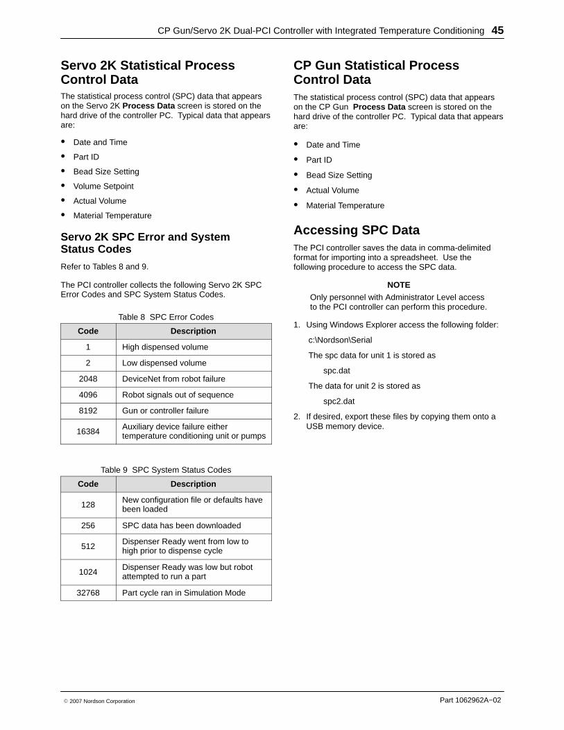
Servo 2K Statistical ProcessControl Data The statistical process control (SPC) data that appearson the Servo 2K Process Data screen is stored on thehard drive of the controller PC. Typical data that appearsare:
� Date and Time
� Part ID
� Bead Size Setting
� Volume Setpoint
� Actual Volume
� Material Temperature
Servo 2K SPC Error and SystemStatus Codes
Refer to Tables 8 and 9.
The PCI controller collects the following Servo 2K SPCError Codes and SPC System Status Codes.
Table 8 SPC Error Codes
Code Description
1 High dispensed volume
2 Low dispensed volume
2048 DeviceNet from robot failure
4096 Robot signals out of sequence
8192 Gun or controller failure
16384Auxiliary device failure eithertemperature conditioning unit or pumps
Table 9 SPC System Status Codes
Code Description
128New configuration file or defaults havebeen loaded
256 SPC data has been downloaded
512Dispenser Ready went from low tohigh prior to dispense cycle
1024Dispenser Ready was low but robotattempted to run a part
32768 Part cycle ran in Simulation Mode
CP Gun Statistical ProcessControl Data The statistical process control (SPC) data that appearson the CP Gun Process Data screen is stored on thehard drive of the controller PC. Typical data that appearsare:
� Date and Time
� Part ID
� Bead Size Setting
� Actual Volume
� Material Temperature
Accessing SPC Data The PCI controller saves the data in comma-delimitedformat for importing into a spreadsheet. Use thefollowing procedure to access the SPC data.
NOTEOnly personnel with Administrator Level accessto the PCI controller can perform this procedure.
1. Using Windows Explorer access the following folder:
c:\Nordson\Serial
The spc data for unit 1 is stored as
spc.dat
The data for unit 2 is stored as
spc2.dat
2. If desired, export these files by copying them onto aUSB memory device.
CP Gun/Servo 2K Dual-PCI Controller with Integrated Temperature Conditioning46
Part 1062962A−02 � 2007 Nordson Corporation
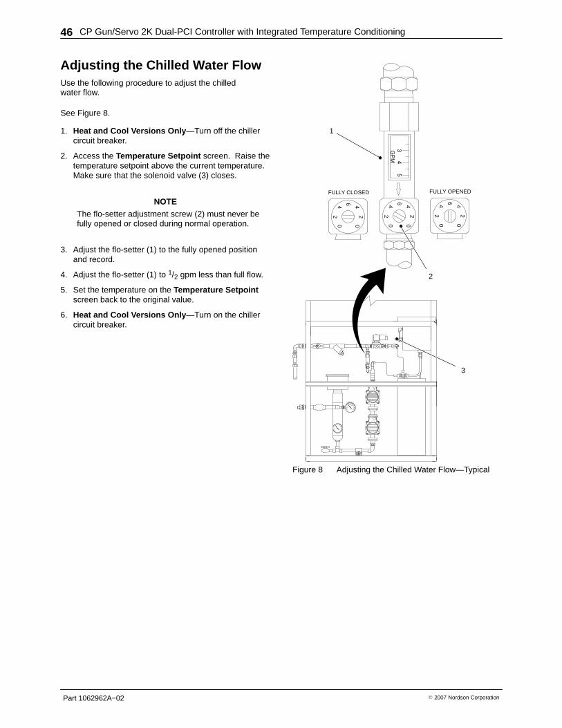
Adjusting the Chilled Water Flow Use the following procedure to adjust the chilledwater flow.
See Figure 8.
1. Heat and Cool Versions Only —Turn off the chillercircuit breaker.
2. Access the Temperature Setpoint screen. Raise thetemperature setpoint above the current temperature.Make sure that the solenoid valve (3) closes.
NOTEThe flo-setter adjustment screw (2) must never befully opened or closed during normal operation.
3. Adjust the flo-setter (1) to the fully opened positionand record.
4. Adjust the flo-setter (1) to 1/2 gpm less than full flow.
5. Set the temperature on the Temperature Setpointscreen back to the original value.
6. Heat and Cool Versions Only —Turn on the chillercircuit breaker.
54
3GP
M6
24
2
0
40
6
24
2
0
40
6
24
2
0
40
FULLY CLOSED FULLY OPENED
2
1
3
Figure 8 Adjusting the Chilled Water Flow—Typical

CP Gun/Servo 2K Dual-PCI Controller with Integrated Temperature Conditioning 47
Part 1062962A−02� 2007 Nordson Corporation
ShutdownUse the following shutdown procedure to remove powerfrom the PCI Controller:
1. See Figure 9. Touch Minimize (1) at the top of ascreen display.
2. Touch start (2) on the Windows task bar to accessthe Start Menu .
3. Touch Shut Down (3) on the Start Menu .
4. Make sure that Shut Down is displayed in theShut Down Windows field. Touch OK (4).
5. Turn the controller off and relieve all pressures.
1
3
4
2
Figure 9 PCI Controller Shutdown
CP Gun/Servo 2K Dual-PCI Controller with Integrated Temperature Conditioning48
Part 1062962A−02 � 2007 Nordson Corporation
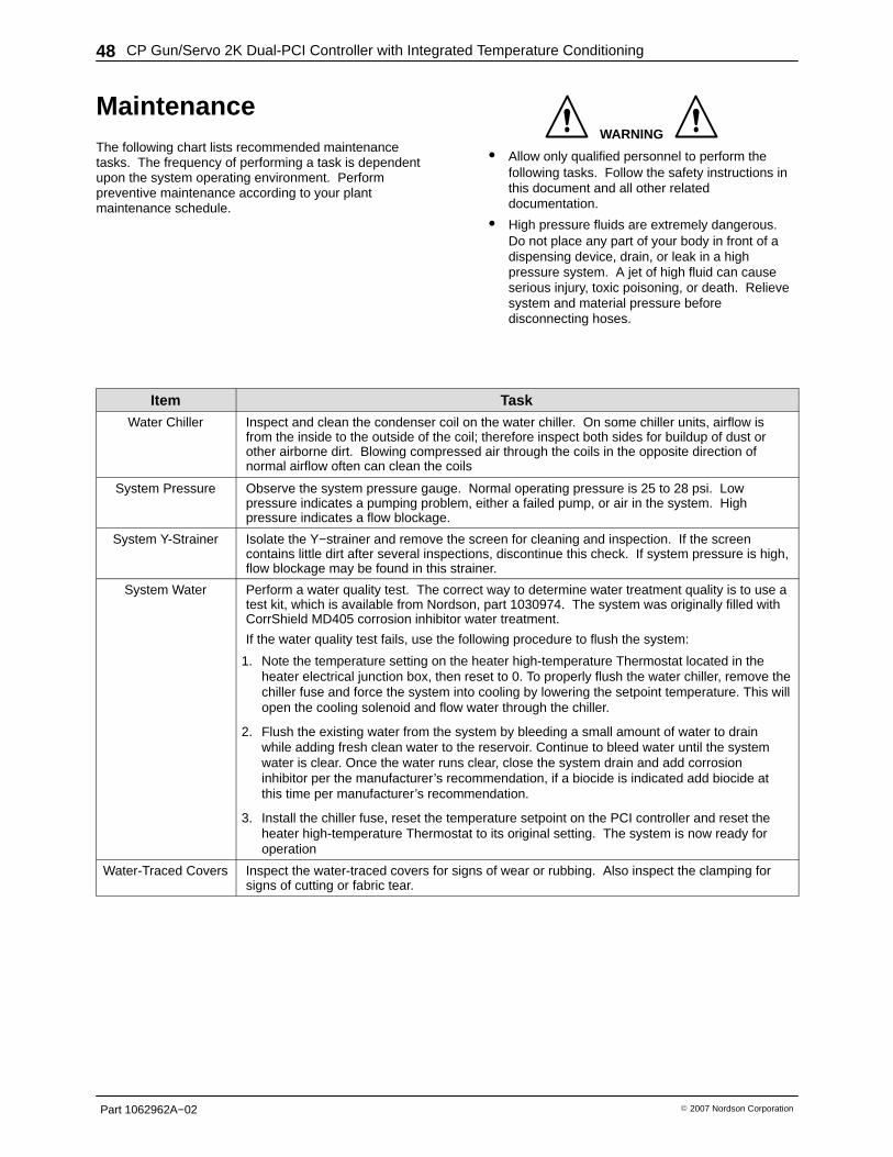
Maintenance The following chart lists recommended maintenancetasks. The frequency of performing a task is dependentupon the system operating environment. Performpreventive maintenance according to your plantmaintenance schedule.
WARNING
� Allow only qualified personnel to perform thefollowing tasks. Follow the safety instructions inthis document and all other relateddocumentation.
� High pressure fluids are extremely dangerous.Do not place any part of your body in front of adispensing device, drain, or leak in a highpressure system. A jet of high fluid can causeserious injury, toxic poisoning, or death. Relievesystem and material pressure beforedisconnecting hoses.
Item TaskWater Chiller Inspect and clean the condenser coil on the water chiller. On some chiller units, airflow is
from the inside to the outside of the coil; therefore inspect both sides for buildup of dust orother airborne dirt. Blowing compressed air through the coils in the opposite direction ofnormal airflow often can clean the coils
System Pressure Observe the system pressure gauge. Normal operating pressure is 25 to 28 psi. Lowpressure indicates a pumping problem, either a failed pump, or air in the system. Highpressure indicates a flow blockage.
System Y-Strainer Isolate the Y−strainer and remove the screen for cleaning and inspection. If the screencontains little dirt after several inspections, discontinue this check. If system pressure is high,flow blockage may be found in this strainer.
System Water Perform a water quality test. The correct way to determine water treatment quality is to use atest kit, which is available from Nordson, part 1030974. The system was originally filled withCorrShield MD405 corrosion inhibitor water treatment.
If the water quality test fails, use the following procedure to flush the system:
1. Note the temperature setting on the heater high-temperature Thermostat located in theheater electrical junction box, then reset to 0. To properly flush the water chiller, remove thechiller fuse and force the system into cooling by lowering the setpoint temperature. This willopen the cooling solenoid and flow water through the chiller.
2. Flush the existing water from the system by bleeding a small amount of water to drainwhile adding fresh clean water to the reservoir. Continue to bleed water until the systemwater is clear. Once the water runs clear, close the system drain and add corrosioninhibitor per the manufacturer’s recommendation, if a biocide is indicated add biocide atthis time per manufacturer’s recommendation.
3. Install the chiller fuse, reset the temperature setpoint on the PCI controller and reset theheater high-temperature Thermostat to its original setting. The system is now ready foroperation
Water-Traced Covers Inspect the water-traced covers for signs of wear or rubbing. Also inspect the clamping forsigns of cutting or fabric tear.
CP Gun/Servo 2K Dual-PCI Controller with Integrated Temperature Conditioning 49
Part 1062962A−02� 2007 Nordson Corporation
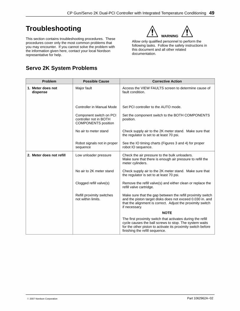
TroubleshootingThis section contains troubleshooting procedures. Theseprocedures cover only the most common problems thatyou may encounter. If you cannot solve the problem withthe information given here, contact your local Nordsonrepresentative for help.
WARNING
Allow only qualified personnel to perform thefollowing tasks. Follow the safety instructions inthis document and all other relateddocumentation.
Servo 2K System Problems
Problem Possible Cause Corrective Action
1. Meter does notdispense
Major fault Access the VIEW FAULTS screen to determine cause offault condition.
Controller in Manual Mode Set PCI controller to the AUTO mode.
Component switch on PCIcontroller not in BOTHCOMPONENTS position
Set the component switch to the BOTH COMPONENTSposition.
No air to meter stand Check supply air to the 2K meter stand. Make sure thatthe regulator is set to at least 70 psi.
Robot signals not in propersequence
See the IO timing charts (Figures 3 and 4) for properrobot IO sequence.
2. Meter does not refill Low unloader pressure Check the air pressure to the bulk unloaders.Make sure that there is enough air pressure to refill themeter cylinders.
No air to 2K meter stand Check supply air to the 2K meter stand. Make sure thatthe regulator is set to at least 70 psi.
Clogged refill valve(s) Remove the refill valve(s) and either clean or replace therefill valve cartridge.
Refill proximity switchesnot within limits.
Make sure that the gap between the refill proximity switchand the piston target disks does not exceed 0.030 in. andthat the alignment is correct. Adjust the proximity switchif necessary.
NOTE
The first proximity switch that activates during the refillcycle causes the ball screws to stop. The system waitsfor the other piston to activate its proximity switch beforefinishing the refill sequence.

CP Gun/Servo 2K Dual-PCI Controller with Integrated Temperature Conditioning50
Part 1062962A−02 � 2007 Nordson Corporation
Problem Possible Cause Corrective Action
3. Bead deposition“wiggles”
Nozzle too high abovework piece
Lower the nozzle. Refer to the robot controller manual.
Material speed throughnozzle too low
Increase the bead size. Refer to Startup in the Operationsection.
Nozzle not large enough Install a larger nozzle. Contact your Nordson Corporationrepresentative for part numbers.
4. Unexpectedbead-size change
Nozzle partially blocked Replace mixer tube.
Material exceededshelf life
Use fresh material.
CP Gun/Servo 2K Dual-PCI Controller with Integrated Temperature Conditioning 51
Part 1062962A−02� 2007 Nordson Corporation
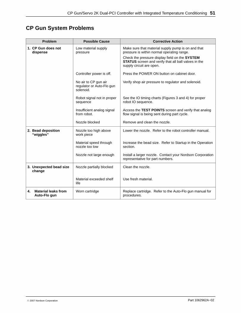
CP Gun System Problems
Problem Possible Cause Corrective Action
1. CP Gun does notdispense
Low material supplypressure
Make sure that material supply pump is on and thatpressure is within normal operating range.
Check the pressure display field on the SYSTEMSTATUS screen and verify that all ball valves in thesupply circuit are open.
Controller power is off. Press the POWER ON button on cabinet door.
No air to CP gun airregulator or Auto-Flo gunsolenoid.
Verify shop air pressure to regulator and solenoid.
Robot signal not in propersequence
See the IO timing charts (Figures 3 and 4) for properrobot IO sequence.
Insufficient analog signalfrom robot.
Access the TEST POINTS screen and verify that analogflow signal is being sent during part cycle.
Nozzle blocked Remove and clean the nozzle.
2. Bead deposition“wiggles”
Nozzle too high abovework piece
Lower the nozzle. Refer to the robot controller manual.
Material speed throughnozzle too low
Increase the bead size. Refer to Startup in the Operationsection.
Nozzle not large enough Install a larger nozzle. Contact your Nordson Corporationrepresentative for part numbers.
3. Unexpected bead sizechange
Nozzle partially blocked Clean the nozzle.
Material exceeded shelflife
Use fresh material.
4. Material leaks fromAuto-Flo gun
Worn cartridge Replace cartridge. Refer to the Auto-Flo gun manual forprocedures.
CP Gun/Servo 2K Dual-PCI Controller with Integrated Temperature Conditioning52
Part 1062962A−02 � 2007 Nordson Corporation
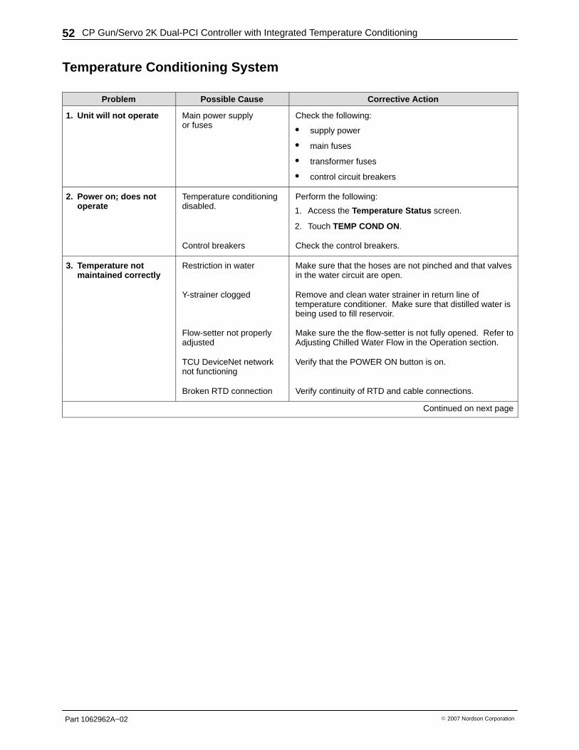
Temperature Conditioning System
Problem Possible Cause Corrective Action
1. Unit will not operate Main power supplyor fuses
Check the following:
� supply power
� main fuses
� transformer fuses
� control circuit breakers
2. Power on; does notoperate
Temperature conditioningdisabled.
Perform the following:
1. Access the Temperature Status screen.
2. Touch TEMP COND ON.
Control breakers Check the control breakers.
3. Temperature notmaintained correctly
Restriction in water Make sure that the hoses are not pinched and that valvesin the water circuit are open.
Y-strainer clogged Remove and clean water strainer in return line oftemperature conditioner. Make sure that distilled water isbeing used to fill reservoir.
Flow-setter not properlyadjusted
Make sure the the flow-setter is not fully opened. Refer toAdjusting Chilled Water Flow in the Operation section.
TCU DeviceNet networknot functioning
Verify that the POWER ON button is on.
Broken RTD connection Verify continuity of RTD and cable connections.
Continued on next page
CP Gun/Servo 2K Dual-PCI Controller with Integrated Temperature Conditioning 53
Part 1062962A−02� 2007 Nordson Corporation
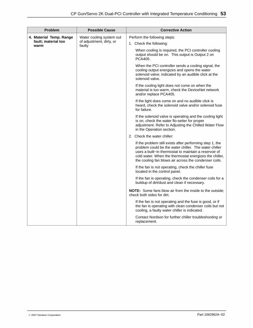
Corrective ActionPossible CauseProblem
4. Material Temp. Rangefault; material toowarm
Water cooling system outof adjustment, dirty, orfaulty
Perform the following steps:
1. Check the following:
When cooling is required, the PCI controller coolingoutput should be on. This output is Output 2 onPCA405.
When the PCI controller sends a cooling signal, thecooling output energizes and opens the watersolenoid valve; indicated by an audible click at thesolenoid valve.
If the cooling light does not come on when thematerial is too warm, check the DeviceNet networkand/or replace PCA405.
If the light does come on and no audible click isheard, check the solenoid valve and/or solenoid fusefor failure.
If the solenoid valve is operating and the cooling lightis on, check the water flo-setter for properadjustment. Refer to Adjusting the Chilled Water Flowin the Operation section.
2. Check the water chiller:
If the problem still exists after performing step 1, theproblem could be the water chiller. The water chilleruses a built−in thermostat to maintain a reservoir ofcold water. When the thermostat energizes the chiller,the cooling fan blows air across the condenser coils.
If the fan is not operating, check the chiller fuselocated in the control panel.
If the fan is operating, check the condenser coils for abuildup of dirt/dust and clean if necessary.
NOTE: Some fans blow air from the inside to the outside;check both sides for dirt.
If the fan is not operating and the fuse is good, or ifthe fan is operating with clean condenser coils but notcooling, a faulty water chiller is indicated.
Contact Nordson for further chiller troubleshooting orreplacement.
CP Gun/Servo 2K Dual-PCI Controller with Integrated Temperature Conditioning54
Part 1062962A−02 � 2007 Nordson Corporation
Corrective ActionPossible CauseProblem
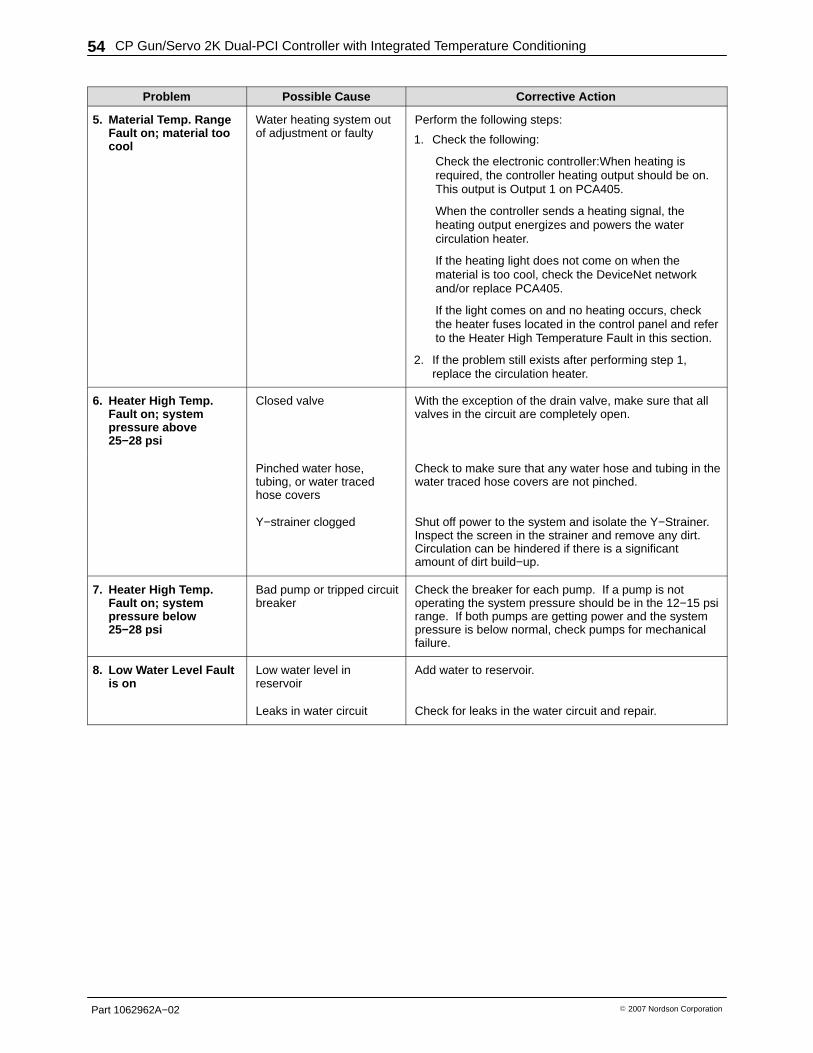
5. Material Temp. RangeFault on; material toocool
Water heating system outof adjustment or faulty
Perform the following steps:
1. Check the following:
Check the electronic controller:When heating isrequired, the controller heating output should be on.This output is Output 1 on PCA405.
When the controller sends a heating signal, theheating output energizes and powers the watercirculation heater.
If the heating light does not come on when thematerial is too cool, check the DeviceNet networkand/or replace PCA405.
If the light comes on and no heating occurs, checkthe heater fuses located in the control panel and referto the Heater High Temperature Fault in this section.
2. If the problem still exists after performing step 1,replace the circulation heater.
6. Heater High Temp.Fault on; systempressure above25−28 psi
Closed valve With the exception of the drain valve, make sure that allvalves in the circuit are completely open.
Pinched water hose,tubing, or water tracedhose covers
Check to make sure that any water hose and tubing in thewater traced hose covers are not pinched.
Y−strainer clogged Shut off power to the system and isolate the Y−Strainer.Inspect the screen in the strainer and remove any dirt.Circulation can be hindered if there is a significantamount of dirt build−up.
7. Heater High Temp.Fault on; systempressure below25−28 psi
Bad pump or tripped circuitbreaker
Check the breaker for each pump. If a pump is notoperating the system pressure should be in the 12−15 psirange. If both pumps are getting power and the systempressure is below normal, check pumps for mechanicalfailure.
8. Low Water Level Faultis on
Low water level inreservoir
Add water to reservoir.
Leaks in water circuit Check for leaks in the water circuit and repair.
CP Gun/Servo 2K Dual-PCI Controller with Integrated Temperature Conditioning 55
Part 1062962A−02� 2007 Nordson Corporation
Cable ContinuityCables should be checked periodically and replacedwhen worn or frayed. If a system malfunctions, makesure that the cable connections are tight.
! CAUTION !Disconnect power before removing cables andtesting them.
Check the cables for continuity with an ohmmeter. Seethe cable wiring diagrams included with your systemdocumentation.
CP Gun/Servo 2K Dual-PCI Controller with Integrated Temperature Conditioning56
Part 1062962A−02 � 2007 Nordson Corporation
RepairRepair consists of replacing the operator interface paneland the PCAs.
WARNING
� Allow only qualified personnel to perform thefollowing tasks. Follow the safety instructions inthis document and all other relateddocumentation.
� Disconnect equipment from the line voltage.Failure to observe this warning may result inpersonal injury, death, or equipment damage.
Operator Interface PanelPerform following procedure to replace the operatorinterface.
1. Turn off and lock out external electrical power tothe controller.
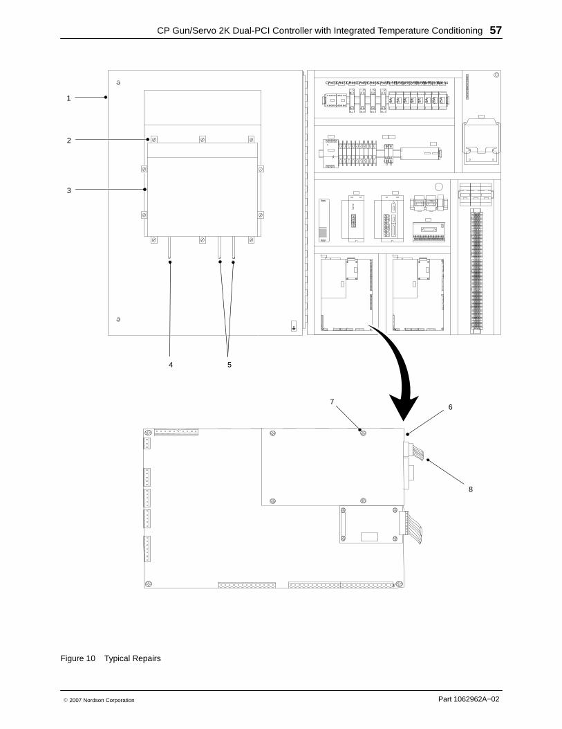
2. See Figure 10. Open the enclosure door (1).
3. Disconnect the AC (4) and Serial (5) cables from theoperator interface (3).
4. Remove the mounting clips (2) securing the operatorinterface (3) to the enclosure door (1). Remove theoperator interface from the enclosure door (1).
NOTE
Do not apply sealing compounds to the operatorinterface. The operator interface has a sealinggasket that forms a compression-type seal.
5. Make sure that the sealing gasket on the operatorinterface (3) is properly positioned.
6. Install the new operator interface (3) into theenclosure door (1).
7. Install the mounting clips (2). Using the torquesequence shown in Figure 10, tighten the mountingclips to 10 in.-lb (1.1 N•m).
8. Connect the AC (4) and Serial (5) cables to theoperator interface (3).
9. Close the enclosure door (1).
Typical PCA ReplacementThe Netburner PCA is used as an example in thefollowing procedure.
WARNING
This unit contains electrostatic sensitivedevices (ESD). Wear a grounding wrist strap toprevent damage to ESD parts.
1. Turn off and lock out external electrical power tothe controller.
2. See Figure 10. Open the enclosure door (1).
3. Disconnect the electrical connector (8) fromthe PCA (6).
4. Remove the screws (7) from the PCA (6).
5. Install the new PCA using the screws (7). Do notover tighten the screws.
6. Connect the electrical connector (8).
7. Close the enclosure door (1).
CP Gun/Servo 2K Dual-PCI Controller with Integrated Temperature Conditioning 57
Part 1062962A−02� 2007 Nordson Corporation
67
FU505FU104A
5A 5A 25A
FU508FU512FU513FU515
5A 5A5A5A
CR455CR459CR456 FU506CR460CR473CR473 FU104
25A
2
4
1
3
5
8
Figure 10 Typical Repairs
CP Gun/Servo 2K Dual-PCI Controller with Integrated Temperature Conditioning58
Part 1062962A−02 � 2007 Nordson Corporation
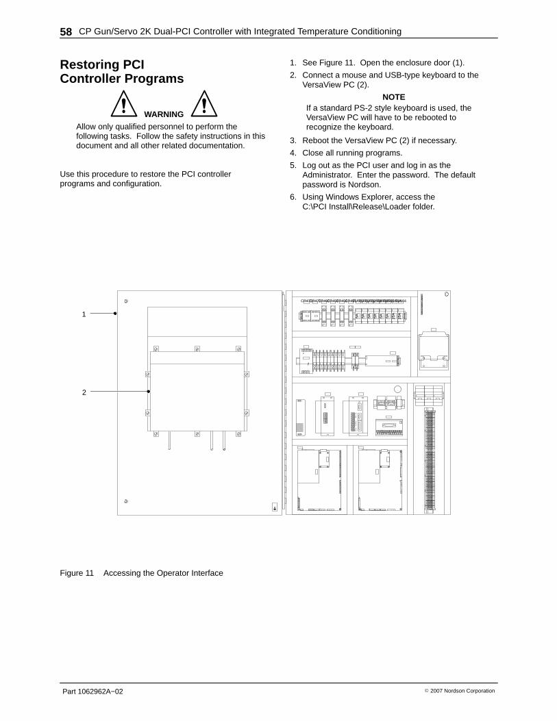
Restoring PCIController Programs
WARNING
Allow only qualified personnel to perform thefollowing tasks. Follow the safety instructions in thisdocument and all other related documentation.
Use this procedure to restore the PCI controllerprograms and configuration.
1. See Figure 11. Open the enclosure door (1).
2. Connect a mouse and USB-type keyboard to theVersaView PC (2).
NOTEIf a standard PS-2 style keyboard is used, theVersaView PC will have to be rebooted torecognize the keyboard.
3. Reboot the VersaView PC (2) if necessary.
4. Close all running programs.
5. Log out as the PCI user and log in as theAdministrator. Enter the password. The defaultpassword is Nordson.
6. Using Windows Explorer, access theC:\PCI Install\Release\Loader folder.
FU505FU104A
5A 5A 25A
FU508FU512FU513FU515
5A 5A5A5A
CR455CR459CR456 FU506CR460CR473CR473 FU104
25A1
2
Figure 11 Accessing the Operator Interface
CP Gun/Servo 2K Dual-PCI Controller with Integrated Temperature Conditioning 59
Part 1062962A−02� 2007 Nordson Corporation
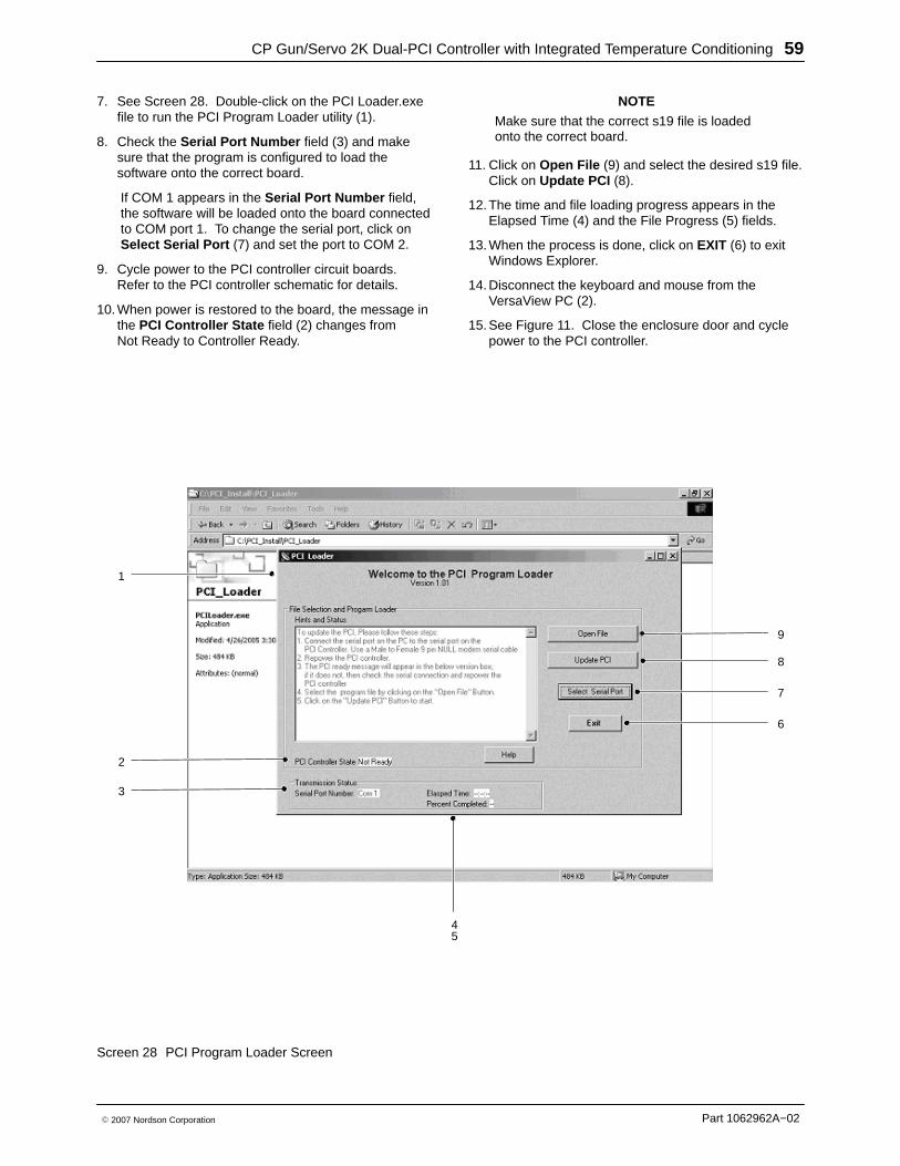
7. See Screen 28. Double-click on the PCI Loader.exefile to run the PCI Program Loader utility (1).
8. Check the Serial Port Number field (3) and makesure that the program is configured to load thesoftware onto the correct board.
If COM 1 appears in the Serial Port Number field,the software will be loaded onto the board connectedto COM port 1. To change the serial port, click onSelect Serial Port (7) and set the port to COM 2.
9. Cycle power to the PCI controller circuit boards.Refer to the PCI controller schematic for details.
10. When power is restored to the board, the message inthe PCI Controller State field (2) changes fromNot Ready to Controller Ready.
NOTE
Make sure that the correct s19 file is loadedonto the correct board.
11. Click on Open File (9) and select the desired s19 file.Click on Update PCI (8).
12. The time and file loading progress appears in theElapsed Time (4) and the File Progress (5) fields.
13. When the process is done, click on EXIT (6) to exitWindows Explorer.
14. Disconnect the keyboard and mouse from theVersaView PC (2).
15. See Figure 11. Close the enclosure door and cyclepower to the PCI controller.
1
2
3
45
6
7
8
9
Screen 28 PCI Program Loader Screen
CP Gun/Servo 2K Dual-PCI Controller with Integrated Temperature Conditioning60
Part 1062962A−02 � 2007 Nordson Corporation
Saving and Loading PCIController Configurations
WARNING Allow only qualified personnel to perform thefollowing tasks. Follow the safety instructions in thisdocument and all other related documentation.
NOTELoading a configuration file from a floppy diskdoes not require a keyboard. Proceed to theLoading Configurations procedure.
1. See Figure 11. Open the enclosure door (1).
2. Connect a USB-type keyboard to the VersaView PCto enter a file name and save configuration data ontoa floppy disk or the hard drive.
NOTEIf a standard PS-2 style keyboard is used, theVersaView PC will have to be rebooted torecognize the keyboard.
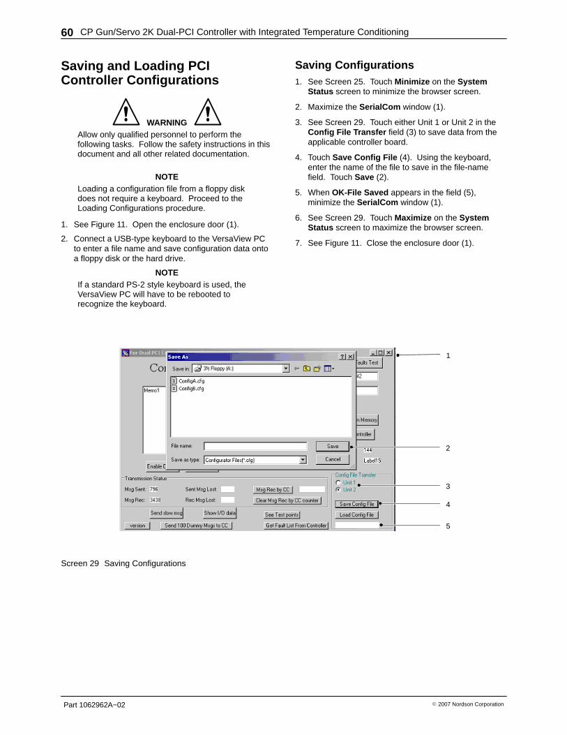
Saving Configurations 1. See Screen 25. Touch Minimize on the System
Status screen to minimize the browser screen.
2. Maximize the SerialCom window (1).
3. See Screen 29. Touch either Unit 1 or Unit 2 in theConfig File Transfer field (3) to save data from theapplicable controller board.
4. Touch Save Config File (4). Using the keyboard,enter the name of the file to save in the file-namefield. Touch Save (2).
5. When OK-File Saved appears in the field (5),minimize the SerialCom window (1).
6. See Screen 29. Touch Maximize on the SystemStatus screen to maximize the browser screen.
7. See Figure 11. Close the enclosure door (1).
1
4
5
3
2
Screen 29 Saving Configurations
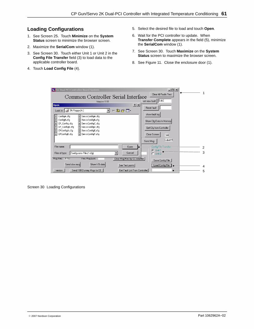
CP Gun/Servo 2K Dual-PCI Controller with Integrated Temperature Conditioning 61
Part 1062962A−02� 2007 Nordson Corporation
Loading Configurations 1. See Screen 25. Touch Minimize on the System
Status screen to minimize the browser screen.
2. Maximize the SerialCom window (1).
3. See Screen 30. Touch either Unit 1 or Unit 2 in theConfig File Transfer field (3) to load data to theapplicable controller board.
4. Touch Load Config File (4).
5. Select the desired file to load and touch Open .
6. Wait for the PCI controller to update. WhenTransfer Complete appears in the field (5), minimizethe SerialCom window (1).
7. See Screen 30. Touch Maximize on the SystemStatus screen to maximize the browser screen.
8. See Figure 11. Close the enclosure door (1).
1
3
4
2
5
Screen 30 Loading Configurations
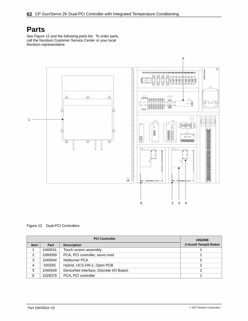
CP Gun/Servo 2K Dual-PCI Controller with Integrated Temperature Conditioning62
Part 1062962A−02 � 2007 Nordson Corporation
PartsSee Figure 12 and the following parts list. To order parts,call the Nordson Customer Service Center or your localNordson representative.
FU505FU104A
5A 5A 25A
FU508FU512FU513FU515
5A 5A5A5A
CR455CR459CR456 FU506CR460CR473CR473 FU104
25A
1
42 3
5
6
Figure 12 Dual-PCI Controllers
PCI Controller 1052008
Item Part Description
10520082-Gun/2-Temp/2-Robo t
1 1040541 Touch screen assembly 12 1060059 PCA, PCI controller, servo mod 13 1040544 Netburner PCA 24 320255 Hybrid, UCS-ON-1, Open PCB 25 1040549 DeviceNet Interface, Discrete I/O Board, 26 1028379 PCA, PCI controller 1
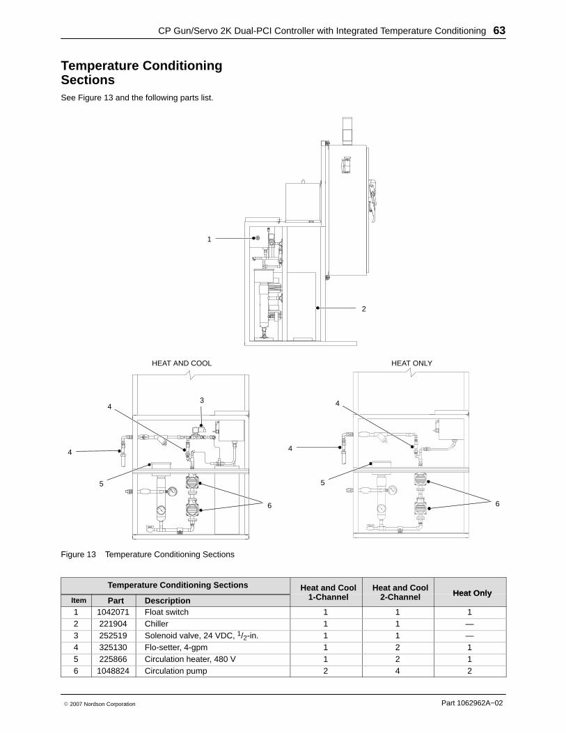
CP Gun/Servo 2K Dual-PCI Controller with Integrated Temperature Conditioning 63
Part 1062962A−02� 2007 Nordson Corporation
Temperature ConditioningSections See Figure 13 and the following parts list.
1
2
3
6
4
5
6
HEAT AND COOL HEAT ONLY
4
4
5
4
Figure 13 Temperature Conditioning Sections
Temperature Conditioning Sections Heat and Coo l1-Channel
Heat and Coo l2-Channel Heat Only
Item Part Description
Heat and Cool1-Channel
Heat and Cool2-Channel Heat Only
1 1042071 Float switch 1 1 12 221904 Chiller 1 1 —3 252519 Solenoid valve, 24 VDC, 1/2-in. 1 1 —4 325130 Flo-setter, 4-gpm 1 2 15 225866 Circulation heater, 480 V 1 2 16 1048824 Circulation pump 2 4 2

CP Gun/Servo 2K Dual-PCI Controller with Integrated Temperature Conditioning64
Part 1062962A−02 � 2007 Nordson Corporation
Accessories and KitsThese accessories may be purchased separately.
Part Description
281132 Valve, proportional assembly
CablesUse this list to order replacement cables of the correcttype and length.
Part Description
330299 Cable, 16 pin, 70 ft
1058761 Cable, 24 pin, 70 ft
CorrShield MD405
NOTESimilar products are available from other watertreatment manufacturers. Concentrations may differ,therefore it is important to follow the manufacturer’srecommendations for products other thanCorrshield MD405.
Part Description
1030974 BetzDearborn 2040 Molybdate Test Kit
1042028 1 pint (16 oz) bottle; treats 10.5gallons of water
1030973 1 quart (32 oz) bottle; treats 21 gallonsof water.
SpecificationsInput Power: TYP 480 V, 3 ∅, , 60 Hz, 25 AInterface Voltage; 24 Vdc
Schematics and WiringDiagrams See the system documentation for the schematics andwiring diagrams that are specific to your system.
Controller Schematic10520082-Gun/2-Robot/2-Temperature 1052020