Embed Size (px)
Citation preview
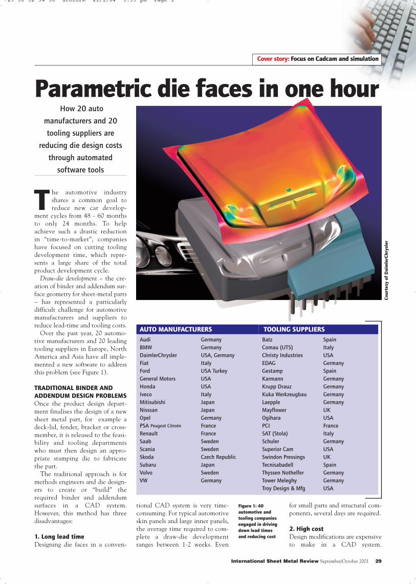
The automotive industryshares a common goal toreduce new car develop-
ment cycles from 48 - 60 monthsto only 24 months. To helpachieve such a drastic reductionin “time-to-market”, companieshave focused on cutting toolingdevelopment time, which repre-sents a large share of the totalproduct development cycle.
Draw-die development – the cre-ation of binder and addendum sur-face geometry for sheet-metal parts– has represented a particularlydifficult challenge for automotivemanufacturers and suppliers toreduce lead-time and tooling costs.
Over the past year, 20 automo-tive manufacturers and 20 leadingtooling suppliers in Europe, NorthAmerica and Asia have all imple-mented a new software to addressthis problem (see Figure 1).
TRADITIONAL BINDER AND
ADDENDUM DESIGN PROBLEMS
Once the product design depart-ment finalises the design of a newsheet metal part, for example adeck-lid, fender, bracket or cross-member, it is released to the feasi-bility and tooling departmentswho must then design an appro-priate stamping die to fabricatethe part.
The traditional approach is formethods engineers and die design-ers to create or “build” therequired binder and addendumsurfaces in a CAD system.However, this method has threedisadvantages:
1. Long lead time
Designing die faces in a conven-
Cover story: Focus on Cadcam and simulation
for small parts and structural com-ponents, several days are required.
2. High cost
Design modifications are expensiveto make in a CAD system.
Co
urt
esy o
f D
aim
lerC
hry
sle
r
International Sheet Metal Review September/October 2001 29
Parametric die faces in one hour
tional CAD system is very time-consuming. For typical automotiveskin panels and large inner panels,the average time required to com-plete a draw-die developmentranges between 1-2 weeks. Even
How 20 auto
manufacturers and 20
tooling suppliers are
reducing die design costs
through automated
software tools
Audi
BMW
DaimlerChrysler
Fiat
Ford
General Motors
Honda
Iveco
Mitisubishi
Nisssan
Opel
PSA Peugeot Citroën
Renault
Saab
Scania
Skoda
Subaru
Volvo
VW
Germany
Germany
USA, Germany
Italy
USA Turkey
USA
USA
Italy
Japan
Japan
Germany
France
France
Sweden
Sweden
Czech Republic
Japan
Sweden
Germany
Batz
Comau (UTS)
Christy Industries
EDAG
Gestamp
Karmann
Krupp Drauz
Kuka Werkzeugbau
Laepple
Mayflower
Ogihara
PCI
SAT (Stola)
Schuler
Superior Cam
Swindon Pressings
Tecnisabadell
Thyssen Nothelfer
Tower Meleghy
Troy Design & Mfg
Spain
Italy
USA
Germany
Spain
Germany
Germany
Germany
Germany
UK
USA
France
Italy
Germany
USA
UK
Spain
Germany
Germany
USA
AUTO MANUFACTURERS TOOLING SUPPLIERS
Figure 1: 40
automotive and
tooling companies
engaged in driving
down lead times
and reducing cost
29 30 32 34 36 utoform 21/1/04 3:39 pm Page 1

Successful draw-die developmentsrequire the expertise of die designersand methods engineers with manyyears of practical experience andgood CAD skills. Almost always,they make several iterations of designmodifications before finalising a goodstamping die (e.g. changing radii,adjusting drawbars). However, mak-ing such design modifications in ageneral purpose CAD system is cum-bersome and slow. Mistakes, modifi-cations, and especially the design ofdifferent “what-if” concepts for thebinder and addendum, are costly.
Furthermore, when time runs outdue to production deadlines, compa-nies are forced to carry out toolingtry-outs in the press, which is evenmore costly.
3. Low throughput
With a manual, CAD-basedapproach, the die designer must waituntil the die surfaces are completed –several days or weeks – before carry-ing out virtual try-out simulations tocheck his designs for cracks, wrinklesand other stamping criteria. It is farmore productive and cost-effective ifthe die designer immediately triesout his die concepts, discards unfeasi-ble designs early on, and concen-trates on further developing only hisbest design(s).
As a result of these drawbacks, sev-eral automotive companies partici-pated in a program to develop a faster,more efficient and less costly methodfor die face design.
PARAMETRIC AND FULLY
INTEGRATED SOFTWARE
AutoForm-DieDesigner software isthe result of a development effortled by AutoForm EngineeringGmbH (developers of sheet metalforming software) in cooperationwith tooling departments at BMWand Audi, and with technical feed-back from DaimlerChrysler andGeneral Motors.
The software reduces toolingdevelopment time through rapidparametric design of die faces, andtheir immediate verification andoptimisation with integrated stamp-ing simulation modules.
It is specialised for generatingbinder and addendum surfaces, and
for evaluating the feasibility of draw-die developments and prototypetools. Its three most important inno-vations are:• Fully parametric features,• Complete integration with virtual
try-out software modules, and• An automatic optimiser.
The software’s parametricapproach is based on analytical engi-neering principles. It also conforms tothe die engineering practice of usingsurface profiles (arcs and angles) todesign die faces and is compatiblewith various CAD data formats.
DIE FACES COMPLETE DRAW-DIE
DEVELOPMENTS IN ONE HOUR
Using the software, it takes about onehour to design the complete die facesstarting from only the CAD surfacedata of the part. This includes the fol-lowing steps:
30 September/October 2001 International Sheet Metal Review
• Determination of tip-angle• Filleting of sharp edges
(variable radii)• Filling of holes• Part modifications (morphing)• Design of the fill surface between
double-attached parts• Over-crowning• Binder design• Design of outer (and if required,
inner) addendum• Unfolding of flanges • Generation of the tools
As all the generated die surfacesare parametric, subsequent modifica-tions (die engineering changes) areimplemented in seconds. These diesurfaces and simulation results caneasily be exported using IGES,VDAFS or mesh formats to othersoftware applications, e.g. pattern-making, structural/crash analysismodules, etc.
The software reduces tooling developmenttime through rapid parametric design ofdie faces, and their immediate verificationand optimisation with integrated stampingsimulation modules.
Co
urt
esy o
f B
MW
Dr. Volker Steininger and
Dr. Vallury PrabhakarAUTHORS:
Cover story: Focus on Cadcam and simulation
29 30 32 34 36 utoform 21/1/04 3:39 pm Page 2

EASY PART DESIGN
MODIFICATIONS
As almost all part designs are sub-ject to revisions and improve-ments even after they have been“officially released” to the diedesign department, the softwareallows for this.
After the parameterised binderand addendum have been createdfor a specific part, one can thenreplace that part with another (sim-ilar) part designwith a modifieddesign and the software will auto-matically adjust the binder andaddendum accordingly.
This is an important time-sav-ing feature as it allows the originaladdendum and binder geometrythat is created, to be re-used forfuture design revisions of the part.
In addition, automatic filletingand the ability to vary fillet radiion the part geometry, saves con-siderable time and allows virtualtry-outs to be carried out earlier inthe product and tooling develop-ment cycles.
.DIRECT PARAMETRIC LINK TO
STAMPING SIMULATION
SOFTWARE
As a result of the software’s inte-grated system approach and fullparametric linking, all die facedesigns can be immediately evalu-ated with one-step or incrementalsimulation modules.
One-step simulation results areconsiderably more reliable whenbased on the complete die face – asgenerated by the software – ratherthan on the part only. An addedbenefit is that these refined resultsare made possible earlier in thedesign cycle. They are availablewithin a few minutes and includethe required blank outline and var-ious stamping feasibility criteria(see Figure 5).
The incremental module is usedfor high accuracy and virtual try-outsof the complete stamping process.Results include predictions of wrin-kles, cracks, skid and impact lines,surface quality, etc. Incremental try-out results are typically availablewithin 1 hour to 3 hours, dependingon the size and complexity of thepart and the desired accuracy.
Additional try-outs can belaunched at once because of para-metric linking. For example,based on the initial results, theuser can make modifications tothe addendum geometry, and the
various tool geometries requiredfor the next simulations are auto-matically updated. Similarly, ifthe user modifies the punch open-ing line, drawbead positions areautomatically adjusted.
32 September/October 2001 International Sheet Metal Review
Figure 2-A: The part geometry (CAD surfaces) of an Audi TT rear fender.
Figure 2-B: The initial binder surface (yellow) automatically created in a few seconds, using
only the CAD surface data in Figure 2-A as input. The user can then modify the binder
geometry with surface profiles.
DESIGN OF PARAMETRIC DIE FACES FOR AUDI TT
Figure 2-C: View of the automatically generated addendum surface (red), based on default
profiles.
Co
urt
esy o
f A
ud
i
Cover story: Focus on Cadcam and simulation
29 30 32 34 36 utoform 21/1/04 3:39 pm Page 3

34 September/October 2001 International Sheet Metal Review
Dr. Volker Steininger, General Manager, AutoForm Engineering Deutschland GmbH
Tel +49 231 9742 320
Fax +49 231 9742 322
E-mail: [email protected]
CONTACT (EUROPE):
Figure 3-A: A typical addendum profile (red line) and its defining parameters. Within a few
seconds, the user can change these “master” global profile parameters, for example to
increase the die radius.
In addition, the user can also make local surface modifications to the addendum, by
changing local profile parameters or directly manipulating contours such as the punch
opening line, bar height, etc.
Figure 3-B: A drawbar that is created by modifying the parameters
of local addendum profiles (black).
Figure 4: The complete die face for the Audi TT rear fender, created
in about 1 hour using 28 customised surface profiles.
ONE-STEP FORMABILITY
SIMULATION Figure 5: The results of a one-step
simulation taking into account the binder
and addendum from Figure 4.
The stamping feasibility results were
calculated in 2 minutes. The colour plot
shows a summary of various stamping
feasibility criteria. The circled area on the
left shows a risk of wrinkles on the
addendum, very near to the part boundary.
The circled area on the right shows a
crack.
Based on one-step results, the general
die concept can be evaluated early in the
design cycle, and if necessary,
modifications to the part geometry can be
recommended. Furthermore, the resulting
blank outline can be used to design the
initial blank outline for an incremental
virtual try-out.
Cover story: Focus on Cadcam and simulation
29 30 32 34 36 utoform 21/1/04 3:40 pm Page 4

AUTOMATIC OPTIMISATION OF
TOOLING AND STAMPING
PROCESS
To further improve the die facedesigns, the software includes anintegrated optimiser module.The user first specifies the allow-able ranges for tool geometry andstamping parameters. The opti-miser then automatically deter-mines the “best” design withinthese ranges through multipleone-step or incremental simula-tions, to achieve the target func-tion: for example, elimination ofcracks and wrinkles, uniform sur-face stretching, no excessivethinning. Tool geometry parame-ters include part, die and drawbarradii, drawbar height, wallangles, over-crown, etc.Stamping parameters includebinder forces, drawbead strength,blank outline, etc.
Benefits
Within the first year of usingAutoForm-DieDesigner, automanufacturers and tooling sup-pliers have already reported thefollowing savings:
• Reduced binder development time by 60%
• Reduction by a factor of 4-5,in the time from CAD partdesign until completed virtualtry-outs
• Reduction of die face development time from one weekdown to one day
• Almost 50% reduction inactual die try-out time andtooling costs
• Two week reduction of toolingdevelopment time, by usingthe generated die faces toorder castings for the dies.
Although it is too early toquantify all benefits, companiesalso expect improved partquality and stamping reliabilitydue to the optimisation oftheir designs. ISMR
36 September/October 2001 International Sheet Metal Review
Dr. Vallury Prabhakar, General Manager, AutoForm Engineering USA Inc.
Tel: +1 888 428-8636
Fax: +1 888 528-8636
E-mail: [email protected]
www.autoform.de
INCREMENTAL STAMPING TRY-OUT SIMULATION
Figure 6: The results of an accurate incremental try-out simulation of the complete stamping process, using the die
faces from Figure 4.
The colour plot shows the predicted thickness distribution; excessive thinning zones are in red and yellow (two
circled areas on the right). The simulation also shows wrinkles in the circled area on the left. These try-out results
were obtained in about 50 minutes.
The die designer can then make modifications to his original die concept to smooth out the wrinkles and
eliminate the cracks, for example by changing drawbar and wall heights, radii, etc. Furthermore, results such as
wrinkling, splitting, skid mark progression, etc. can be visualised at each step of the drawing process.
OPTIMISATION
Figure 7: The results of optimisation of the initial incremental try-out in Figure 6.
The two crack zones were eliminated and the wrinkling zone was minimised and moved away from the part
boundary.
Automatic optimisation can help the die designer to find the best parameters for his design. It can also help the
process engineer to determine the best stamping conditions.
Cover story: Focus on Cadcam and simulation
CONTACT (USA):
29 30 32 34 36 utoform 21/1/04 3:40 pm Page 5