Embed Size (px)
Citation preview

Cover headlineCover headline38999-Style Connectors

www.ittcannon.com
Dimensions shown in inches (mm) Specifications and dimensions subject to change
Cannon 38999-Style Series I, II, III Connectors
ITT Cannon connectors set the industry standard for performance and reliability in the most demanding conditions and harshest environments. Our 38999-Style Series I, II, III Connectors are designed to withstand the extreme shock, exposure and vibration that are commonplace in Defense and Commercial Aerospace applications.
We offer lightweight, space-saving solutions to our military customers, coupled with high bandwidth and high power for severe service application needs. More than a century of experience, coupled with unparalleled engineering and testing resources, has established ITT Cannon as one of the premier providers of interconnect solutions worldwide.
With a proven track record for engineering and manufacturing excellence, ITT Cannon continues to deliver a broad range of innovative products and solutions that enable our customers to meet their most demanding design requirements, where impeccable reliability and safety are essential.
Example Application Areas• Defense
– Military aircraft– Military communication systems– Hand held and vehicle platforms– Military ground support systems– Military computer systems– Harsh environment platforms– Blind mate applications– High density, low signal platforms– Hand held and vehicle platforms– Unmanned systems
• Aerospace– Aircraft engines– General electric testing equipment– Commercial business aviation– Aerospace launch vehicles
www.ittcannon.com
Dimensions shown in inches (mm) Specifications and dimensions subject to change
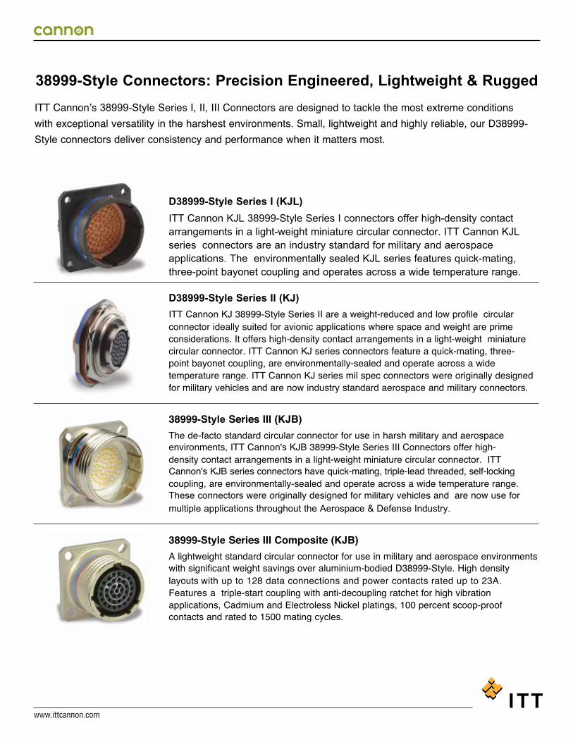
38999-Style Connectors: Precision Engineered, Lightweight & Rugged ITT Cannon’s 38999-Style Series I, II, III Connectors are designed to tackle the most extreme conditions with exceptional versatility in the harshest environments. Small, lightweight and highly reliable, our D38999-Style connectors deliver consistency and performance when it matters most.
D38999-Style Series I (KJL)ITT Cannon KJL 38999-Style Series I connectors offer high-density contact arrangements in a light-weight miniature circular connector. ITT Cannon KJL series connectors are an industry standard for military and aerospace applications. The environmentally sealed KJL series features quick-mating, three-point bayonet coupling and operates across a wide temperature range.
D38999-Style Series II (KJ)ITT Cannon KJ 38999-Style Series II are a weight-reduced and low profile circular connector ideally suited for avionic applications where space and weight are prime considerations. It offers high-density contact arrangements in a light-weight miniature circular connector. ITT Cannon KJ series connectors feature a quick-mating, three-point bayonet coupling, are environmentally-sealed and operate across a wide temperature range. ITT Cannon KJ series mil spec connectors were originally designed for military vehicles and are now industry standard aerospace and military connectors.
38999-Style Series III (KJB)The de-facto standard circular connector for use in harsh military and aerospace environments, ITT Cannon's KJB 38999-Style Series III Connectors offer high-density contact arrangements in a light-weight miniature circular connector. ITT Cannon's KJB series connectors have quick-mating, triple-lead threaded, self-locking coupling, are environmentally-sealed and operate across a wide temperature range. These connectors were originally designed for military vehicles and are now use for multiple applications throughout the Aerospace & Defense Industry.
38999-Style Series III Composite (KJB)A lightweight standard circular connector for use in military and aerospace environments with significant weight savings over aluminium-bodied D38999-Style. High density layouts with up to 128 data connections and power contacts rated up to 23A. Features a triple-start coupling with anti-decoupling ratchet for high vibration applications, Cadmium and Electroless Nickel platings, 100 percent scoop-proof contacts and rated to 1500 mating cycles.

www.ittcannon.com
Dimensions shown in inches (mm) Specifications and dimensions subject to change
2
In addition to our 38999-style series, we also offer these connectivity solutions:
Combo D-Sub Product offering includes ability to integrate signal and coax, high power, and high voltage.
CA-Bayonet – Signal and power connectors with exceptional sealing against the ingress of fluids and will withstand the effects of high vibrations.
Microminiature – High performance and reliability with exceptional versatility. Available in rectangular, circular and strip configurations, many of our connectors are designed to be comparable to the MIL-DTL-83513 specification.
Specifications and Test Data ..............................................................................................................................................3-5
38999-Style Series I ............................................................................................................................................................6-9
38999-StyleSeries II ........................................................................................................................................................10-15
38999-Style Series III ......................................................................................................................................................16-18
38999-Style Series III Composite ....................................................................................................................................19-20
Polarizing Positions ..............................................................................................................................................................21
Contact Arrangements ....................................................................................................................................................22-23
Contacts ..........................................................................................................................................................................24-27
Torque Values / Wire Dimensions........................................................................................................................................28
Backshells .......................................................................................................................................................................29-31
Tools .....................................................................................................................................................................................32
Assembly Instructions ..........................................................................................................................................................33
Specifications .......................................................................................................................................................................34
Product Safety and Warranty ...............................................................................................................................................35
About ITT Cannon ................................................................................................................................................................36
Table of Contents
www.ittcannon.com
Dimensions shown in inches (mm) Specifications and dimensions subject to change
3
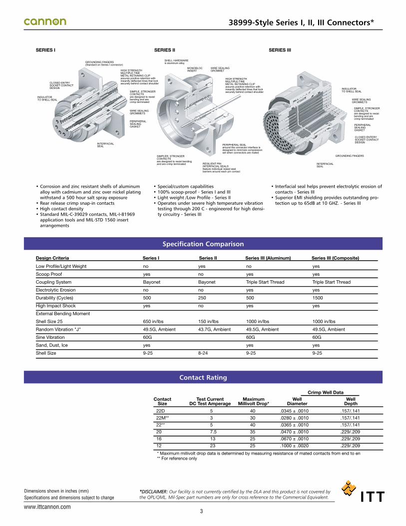
38999-Style Series I, II, III Connectors*
• Corrosion and zinc resistant shells of aluminumalloy with cadmium and zinc over nickel platingwithstand a 500 hour salt spray exposure
• Rear release crimp snap-in contacts• High contact density• Standard MIL-C-39029 contacts, MIL-I-81969
application tools and MIL-STD 1560 insertarrangements
• Special/custom capabilities• 100% scoop-proof - Series I and III• Light weight /Low Profile - Series II• Operates under severe high temperature vibration
testing through 200 C - engineered for high densi-ty circuitry - Series III
CLOSED ENTRYSOCKET CONTACTDESIGN
INSULATORTO SHELL SEAL
GROUNDING FINGERS(Standard on Series I connector)
INTERFACIALSEAL
HIGH STRENGTHMULTIPLE-TINEMETAL RETAINING CLIPassures positive retention withinwardly deflected tines that locksecurely behind contact shoulder
HIGH STRENGTHMULTIPLE-TINEMETAL RETAINING CLIPassures positive retention withinwardly deflected tines that locksecurely behind contact shoulder
HIGH STRENGTHMULTIPLE-TINEMETAL RETAINING CLIPassures positive retentin withinwardly deflected tines that locksecurely behind contact shoulder
INTERFACIALSEAL
GROUNDING FINGERS
CLOSED ENTERYSOCKET CONTACTDESIGN
PERIPHERALSEALINGGASKET
WIRE SEALINGGROMMETS
INSULATORTO SHELL SEAL
SIMPLE, STRONGERCONTACTSare designed to resistbending and arecrimp terminated
SIMPLE, STRONGERCONTACTSare designed to resistbending and arecrimp terminated
WIRE SEALINGGROMMETS
SIMPLER, STRONGERCONTACTSare designed to resist bendingand are crimp terminated RESILIENT PIN
INTERFACIAL SEALSfeature individual raised sealbarriers around each pin contact
PERIPHERAL SEALaround the connector interface isdesigned to minimize compressionset when connectors are mated
PERIPHERALSEALINGGASKET
SHELL HARDWAREis aluminum alloy
MONOBLOCINSERT
WIRE SEALINGGROMMET
SERIES I SERIES II SERIES III
• Interfacial seal helps prevent electrolytic erosion ofcontacts - Series III
• Superior EMI shielding provides outstanding pro-tection up to 65dB at 10 GHZ. - Series III
Specification Comparison
Contact Rating
Design Criteria Series I Series II
Low Profile/Light Weight
Scoop Proof
Coupling System
Electrolytic Erosion
Durability (Cycles)
High Impact Shock
External Bending Moment
Shell Size 25
Random Vibration "J"
Sine Vibration
Sand, Dust, Ice
Shell Size
no
yes
Bayonet
no
500
yes
650 in/lbs
49.5G, Ambient
60G
yes
9-25
yes
no
Bayonet
no
250
no
150 in/lbs
43.7G, Ambient
8-24
Series III (Aluminum)
no
yes
Triple Start Thread
yes
500
yes
1000 in/lbs
49.5G, Ambient
60G
yes
9-25
Series III (Composite)
yes
yes
Triple Start Thread
yes
1500
yes
1000 in/lbs
49.5G, Ambient
60G
yes
9-25
Crimp Well DataContact
Size
22D
22M**
22**
20
16
12
* Maximum millivolt drop data is determined by measuring resistance of mated contacts from end to en** For reference only
5
3
5
7.5
13
23
40
30
40
35
25
25
.0345 ± .0010
.0280 ± .0010
.0365 ± .0010
.0470 ± .0010
.0670 ± .0010
.1000 ± .0020
.157/.141
.157/.141
.157/.141
.229/.209
.229/.209
.229/.209
Test CurrentDC Test Amperage
MaximumMillivolt Drop*
WellDiameter
WellDepth
*DISCLAIMER: Our facility is not currently certified by the DLA and this product is not covered by the QPL/QML. Mil-Spec part numbers are only for cross reference to the Commercial Equivalent.

www.ittcannon.com
Dimensions shown in inches (mm) Specifications and dimensions subject to change
4
Performance and Material Specifications
Test Data
Aluminum CompositeMATERIALS AND FINISHES
ReceptacleShell
Insulator
Contacts
Grommet and Seal
Jam Nut
Grounding Spring
*Finish as noted in How To Order sections.
28
26
24
22
20
18
16
14
12
Sea Level
50,000 ft.
70,000 ft.
100,000 ft.
1300 1300
800 550
800 350
800 200
1800 1800
1000 600
1000 400
1000 200
2300 2300
1000 800
1000 500
1000 200
1.5
2.0
3.0
5.0
-
-
-
-
-
1.5
2.0
3.0
-
-
-
-
-
-
-
2.0
3.0
5.0
-
-
-
-
-
-
-
3.0
5.0
7.5
-
-
-
-
-
-
-
-
7.5
10.0
13.0
-
-
-
-
-
-
-
-
-
17.0
23.0
Aluminum alloy
High grade plastic
Copper alloy, gold plate
Silicone base elastomer
Aluminum alloy
-
Aluminum alloy*
High grade plastic
Copper alloy, gold plate
Silicone base elastomer
-
Beryllium copper
Grounded Plug ReceptacleThermoplastic
High grade plastic
Copper alloy, gold plate
Silicone base elastomer
-
-
Thermoplastic
High grade plastic
Copper alloy, gold plate
Silicone base elastomer
-
Beryllium copper
Grounded Plug
Contact Size and Test AmpsWireSize
AltitudeService Rating M
Mated UnmatedService Rating I
Mated UnmatedService Rating II
Mated Unmated
22D 22M* 22* 20 16 12
ELECTRICAL DATA
Contact Size: 22D, 22M*, 22*, 20, 16 and 12
Service Rating
Test voltage, AC (rms), work voltage to be determined by application
Contact Rating and Wire Size Accomodation
1000 1000
600 400
600 260
600 200
Service Rating NMated Unmated
*For reference only
500 cycles of mating and unmating, 250 cycles for Series II with spring fingers
Class F: EMI leakage attenuation, greater than 90dB at 100Mhz, greater than 65dB at 10 GHz. Shell to shell conductivity, 1.0 millivolt max. resistance.Class W: EMI leakage attenuation, greater than 90dB at 100 MHz, greater than 50dB at 10 GHz. Shell to shell conductivity, 2.5 millivolt max.
Class B, W, and Z will withstand 500 hours salt spray.Class A, F, N, will withstand 48 hours salt spray.
Connectors are fluid resistant to many fuels, solvents, coolants and oils.
Mated conectors terminated with MIL-C-915 cable and environmentally sealed backshells will withstand high impact shock per MIL-S-901. Applicable to Series I & III only.Designed to operate between sea level and 100,000 ft. above sea level.
Mated connectors shall withstand sand and dust per method 110 of MIL-STD-202 and be ice resistant. Applicable to Series I & III only.
NOTE: For hermetic standard or test data please consult ITT.
Mated connectors are vibrated with weights to simulate rear accessory loads to the following levels:Sine Vibration:
Random Vibration:
Up to 60 G's - Series I & III (at rated temperature - Series III)Not applicable for Series II.43.7 Grms at rated temperature - Series III49.5 Grms at Ambient Temperature - Series I & III43.7 Grms at Ambient Temperature - Series II
Test Description Parameters
Durability
Temperature Range
Vibration
EMI Shielding Effectiveness
Corrosion Resistant
Fluid Immersion
High Impact Shock
Altitude
Other Environments
Class F, N; - 65ºC (-85ºF) to + 200ºC (+392ºF) Class A; - 65ºC (-85ºF) to + 150ºC (+302ºF)Class B,W: - 65ºC (-85ºF) to + 175ºC (+347ºF)
38999-Style Series I, II, III Connectors*
*DISCLAIMER: Our facility is not currently certified by the DLA and this product is not covered by the QPL/QML. Mil-Spec part numbers are only for cross reference to the Commercial Equivalent.
*DISCLAIMER: Our facility is not currently certified by the DLA and this product is not covered by the QPL/QML. Mil-Spec part numbers are only for cross reference to the Commercial Equivalent.

www.ittcannon.com
Dimensions shown in inches (mm) Specifications and dimensions subject to change
5
Insert Availability and Identification
SeriesII
8-358-98
10-510-3510-9810-9912-312-412-812-3512-9814-514-1514-18
14-3514-9716-616-816-2616-3516-9918-1118-2818-3018-3218-35
20-1620-3520-3920-41
22-2122-3222-3522-5322-5524-4
24-2424-2924-35
24-61
9-359-9811-411-511-3511-9811-99
13-413-813-3513-9815-515-1515-1815-1915-3515-9717-617-817-2617-3517-9919-1119-2819-3019-3219-3521-1121-1621-3521-3921-4121-7523-2123-3223-3523-5323-5525-425-1925-2425-2925-3525-3725-4325-4625-825-2025-4225-6125-6425-66
MIII
MIIIIII
MIIIIII
MIIIII
MIIIIII
MIIIMII
MIII
MIIIIII
MII
I, TwinaxTwinax
N, Coax, TwinaxI, Coax
III
6345
1367348
22105
151819371268
265523112830326611167939414
2132
100535556192429
1283743468
3042616466
6
13
22
37
55
66
79
100
128
4053
345
67
8
10
141819
8
26
21
262932
3741
32
535548
2340
10386182
34
51
4
8
21121
16
2
21
8
1229
37204
13
1011
6
11
1912
4**
6
4***
2*** 8***3***4*
SeriesI & III
ServiceRating
TotalContacts 22D 20
Contact Size
16 12 8
Coax for RG-180 cablesCoax for RG-174, -179, or -316 cablesTwinax for M17/176-00002 cables(check factory for other cable applications)
***
***
38999-Style Series I, II, III Connectors*
DISCLAIMER:Our facility is not currently certified by the DLA and this product is not covered by the QPL/QML. Mil-Spec part numbers are only for cross reference to the Commercial Equivalent.
*DISCLAIMER: Our facility is not currently certified by the DLA and this product is not covered by the QPL/QML. Mil-Spec part numbers are only for cross reference to the Commercial Equivalent.

www.ittcannon.com
Dimensions shown in inches (mm) Specifications and dimensions subject to change
6
How To Order
SHELL SIZE9, 11, 13, 15, 17, 19, 21, 23, and 25
HARDWARE FINISH STANDARDA - Bright cadmium over electroless nickel plate,
-85ºF to +302ºF (-65ºC to +150ºC)B - Olive drab cadmium over electroless nickel
plate, -85ºF to +347ºF (-65ºC to +175ºC)F - Electroless nickel, -85ºF to +392ºF
(-65ºC to +200ºC)
CONTACT ARRANGEMENT See pages 22 and 23.
MS NUMBER SHELL STYLE
CLASS
SHELL SIZE
HARDWARE FINISH
CONTACT ARRANGEMENT
CONTACT STYLE
POLARIZING POSITION
MS27467-Style T 17 B 35 S
CONTACT STYLEP - PinS - Socket*A - Less Pin Contact*B - Less Socket Contact
*Used only when other than power contacts are tobe installed (i.e. shielded, thermocouple, etc.)
POLARIZING POSITION A,B,C, and D. (No letters required for normal). See page 21.
Note: To order MS connectors less standard power contacts, purchase order must state “Less Contacts”
MS NUMBER SHELL STYLEMS27466 - Wall Mounting ReceptacleMS27468 - Jam Nut ReceptacleMS27467 - Grounded PlugMS27656 - Wall Mounting Receptacle
(back panel mounting)MS27505 - Box Mounting Receptacle
(back panel) (Class E)
CLASSE - Inactive for new design.
Superseded by Class T.G - Environmental resistant Space GradeP - Environment - resistant with straight potting
cup accessoriesT - Environment - resistant with accessory threads
and teeth, except MS27505 (without rear accessory) (Class T not applicable to MS27505)
SERIES PREFIX
SHELL STYLE
CLASS
SHELL SIZE
HARDWARE FINISH
CONTACT ARRANGEMENT
CONTACT STYLE
POLARIZING POSITION
MODIFICATION CODE
KJL 6 T 17 B 35 S N
SHELL SIZE9,11,13,15,17,19,21,23 and 25
HARDWARE FINISH STANDARDA - Bright cadmium over electroless nickel plate,
-85ºF to +302ºF (-65ºC to +150ºC)B - Olive drab cadmium over electroless nickel
plate, -85ºF to +347ºF (-65ºC to + 175ºC)N - Electroless nickel, -85ºF to +392ºF (-65ºC to
+200ºC)Z - Zinc Nickel, Black- - (Dash) When using a finish modification code
CONTACT ARRANGEMENT See pages 22 and 23.
CONTACT STYLEP - PinS - Socket PS - Pin-Socket (Shell style 4 only)
POLARIZING POSITIONN (normal), A, B, C, D. See page 21.
MODIFICATION CODE L - Less contacts, not stamped on connector16 - Outgassed
NASA space graded connector17 - Clinch Nuts installed
4-40 Size 9-21, 6-32 Size 23-25)27 - Outgassed, standard connector A296 - Black Zinc Cobalt, RoHS Compliant
SERIES PREFIXKJL - Series I-Scoop proof
SHELL STYLE0 - Wall mounting receptacle3 - Wall mounting receptacle (back panel
mounting)4 - Thru bulkhead receptacle*5 - Box mounting receptacle (back panel mount-
ing)6 - Straight plug, grounded7 - Jam nut receptacle
CLASSE - Inactive for new design.
Superseded by Class T.G - Environmental resistant - Space GradeF - Environment - resistant with strain relief
accessoryP - Environment - resistant with straight potting
cup accessoryT - Environment - resistant (without rear
accessory) (Class T not applicable to KJL5)
*Consult factory for availability
Military Nomenclature
Cannon Nomenclature
38999-Style Series I Connectors*
DISCLAIMER:Our facility is not currently certified by the DLA and this product is not covered by the QPL/QML. Mil-Spec part numbers are only for cross reference to the Commercial Equivalent.
*DISCLAIMER: Our facility is not currently certified by the DLA and this product is not covered by the QPL/QML. Mil-Spec part numbers are only for cross reference to the Commercial Equivalent.

www.ittcannon.com
Dimensions shown in inches (mm) Specifications and dimensions subject to change
7
Wall Mounting Receptacle
Wall Mounting Receptacle (Back Panel)
ShellSize
ADia. Max.
EMax.
JDia. Max.
LMax.
MMax.
NT.P.
PDia. Max.
TThread
FCable Clamp
Overall Length With Backshells
PPotting Max.
HMax.
NOTE: For backshell dimensions and configurations, see pages 29 and 31.
J DIA. MAX.
POLARIZING KEYWAY
T THREAD
E MAX. PANEL THICKNESS (including mounting hardware)
BLUE BAND (INDICATES REAR RELEASE CONTACT RETENTION SYSTEM)
P DIA.
M N
H
A
L
1.247 (31.67) MAX.
9
11
13
15
17
19
21
23
25
Performance Specifications-Pages 3 and 4. Contacts, Sealing Plugs, Assembly Tools - Pages 24, 31, and 32. Contact Arrangements - Pages 22 and 23.
.573 (14.55)
.701 (17.81)
.851 (21.62)
.976 (24.79)
1.101 (27.97)
1.208 (30.68)
1.333 (33.86)
1.458 (37.03)
1.583 (40.21)
.662 (16.81)
.810 (20.57)
.960 (24.38)
1.085 (27.56)
1.210 (30.73)
1.317 (33.45)
1.442 (36.63)
1.567 (39.80)
1.692 (42.98)
.958 (24.33)
1.051 (26.70)
1.145 (29.08)
1.239 (31.47)
1.332 (33.83)
1.458 (37.03)
1.582 (40.18)
1.708 (43.38)
1.832 (46.53)
.719 (18.26)
.812 (20.62)
.906 (23.01)
.969 (24.61)
1.062 (26.97)
1.156 (29.36)
1.250 (31.75)
1.375 (34.93)
1.500 (38.10)
7/16-28UNEF-2A
9/16-24UNEF-2A
11/16-24UNEF-2A
13/16-20UNEF-2A
15/16-20UNEF-2A
1-1/16-18UNEF-2A
1-3/16-18UNEF-2A
1-5/16-18UNEF-2A
1-7/16-18UNEF-2A
.100 (2.54)
.100 (2.54)
.100 (2.54)
.100 (2.54)
.100 (2.54)
.100 (2.54)
.130 (3.30)
.130 (3.30)
.130 (3.30)
.234 (5.94)
.234 (5.94)
.234 (5.94)
.234 (5.94)
.234 (5.94)
.234 (5.94)
.204 (5.18)
.204 (5.18)
.193 (4.90)
.820 (20.83)
.820 (20.83)
.820 (20.83)
.820 (20.83)
.820 (20.83)
.820 (20.83)
.790 (20.07)
.790 (20.07)
.790 (20.07)
.138 (3.51)
138 (3.51)
.138 (3.51)
.138 (3.51)
.138 (3.51)
.138 (3.51)
.138 (3.51)
.157 (3.99)
.157 (3.99)
1.805 (45.85)
1.805 (45.85)
1.805 (45.85)
1.805 (45.85)
1.935 (48.90)
1.955 (49.66)
1.955 (49.66)
1.955 (49.66)
1.955 (49.66)
1.410 (35.81)
1.410 (35.81)
1.410 (35.81)
1.410 (35.81)
1.410 (35.81)
1.410 (35.81)
1.410 (35.81)
1.410 (35.81)
1.410 (35.81)
MS27656-Style(MS service class E, P, T)
KJL3
MS27466-Style(MS service class E, P, T)
ShellSize
ADia. Max.
HMax.
LMax.
MMax.
NT.P.
PDia. Max.
TThread
FCable Clamp
Overall Length With BackshellsP
Potting Max.J
Dia. Max.
KJL0
M N
J DIA. MAX.
POLARIZING KEYWAY
P DIA.
1.240 (31.50) MAX.
L
H
A
T THREAD
BLUE BAND (INDICATES REAR RELEASE CONTACT RETENTION SYSTEM)
NOTE: For backshell dimensions and configurations, see pages 29 and 31.
9
11
13
15
17
19
21
23
25
.573 (14.55)
.701 (17.81)
.851 (21.62)
.976 (24.79)
1.101 (27.97)
1.208 (30.68)
1.333 (33.86)
1.458 (37.03)
1.583 (40.21)
.662 (16.81)
.810 (20.57)
.960 (24.38)
1.085 (27.56)
1.210 (30.73)
1.317 (33.45)
1.442 (36.63)
1.567 (39.80)
1.692 (42.98)
.958 (24.33)
1.051 (26.70)
1.145 (29.08)
1.239 (31.47)
1.332 (33.83)
1.458 (37.03)
1.582 (40.18)
1.708 (43.38)
1.832 (46.53)
.719 (18.26)
.812 (20.62)
.906 (23.01)
.969 (24.61)
1.062 (26.97)
1.156 (29.36)
1.250 (31.75)
1.375 (34.93)
1.500 (38.10)
7/16-28UNEF-2A
9/16-24UNEF-2A
11/16-24UNEF-2A
13/16-20UNEF-2A
15/16-20UNEF-2A
1-1/16-18UNEF-2A
1-3/16-18UNEF-2A
1-5/16-18UNEF-2A
1-7/16-18UNEF-2A
.100 (2.54)
.100 (2.54)
.100 (2.54)
.100 (2.54)
.100 (2.54)
.100 (2.54)
.130 (3.30)
.130 (3.30)
.130 (3.30)
.632 (16.05)
.632 (16.05)
.632 (16.05)
.632 (16.05)
.632 (16.05)
.632 (16.05)
.602 (15.29)
.602 (15.29)
.602 (15.29)
.138 (3.51)
138 (3.51)
.138 (3.51)
.138 (3.51)
.138 (3.51)
.138 (3.51)
.138 (3.51)
.157 (3.99)
.157 (3.99)
1.846 (46.89)
1.846 (46.89)
1.846 (46.89)
1.846 (46.89)
1.966 (49.94)
1.966 (50.70)
1.966 (50.70)
1.966 (50.70)
1.966 (50.70)
1.451 (36.86)
1.451 (36.86)
1.451 (36.86)
1.451 (36.86)
1.451 (36.86)
1.451 (36.86)
1.451 (36.86)
1.451 (36.86)
1.451 (36.86)
38999-Style Series I Connectors*
*DISCLAIMER: Our facility is not currently certified by the DLA and this product is not covered by the QPL/QML. Mil-Spec part numbers are only for cross reference to the Commercial Equivalent.

www.ittcannon.com
Dimensions shown in inches (mm) Specifications and dimensions subject to change
8
38999-Style Series I Connectors*
Box Mounting Receptacle (Back Panel)
Straight Plug Grounded
ShellSize
AMax.
JDia. Max.
LMax.
(Class T)T
ThreadF
Cable Clamp
Overall Length With BackshellsP
Potting Max.
NOTE: For backshell dimensions and configurations, see pages 29 and 31.
J DIA. POLARIZING KEYWAY T THREAD
BLUE BAND (INDICATES REAR RELEASE CONTACT RETENTION SYSTEM)
G DIA. MAX.
A DIA.
L
9
11
13
15
17
19
21
23
25
Performance Specifications-Pages 3 and 4.
Contacts, Sealing Plugs, Assembly Tools - Pages 24, 31 and 32.
Contact Arrangements - Pages 22 and 23.
.585 (14.86)
.717 (18.21)
.866 (22.00)
.990 (25.15)
1.115 (28.32)
1.222 (31.04)
1.347 (34.21)
1.472 (37.39)
1.597 (40.56)
.483 (12.27)
.611 (15.52)
.760 (19.30)
.885 (22.48)
1.010 (25.65)
1.115 (28.32)
1.240 (31.50)
1.365 (34.67)
1.490 (37.85)
GDia. Max.
.859 (21.82)
.984 (24.99)
1.156 (29.36)
1.281 (32.54)
1.406 (35.71)
1.516 (38.51)
1.641 (41.68)
1.766 (44.86)
1.891 (48.03)
7/16-28UNEF-2A
9/16-24UNEF-2A
11/16-24UNEF-2A
13/16-20UNEF-2A
15/16-20UNEF-2A
1-1/16-18UNEF-2A
1-3/16-18UNEF-2A
1-5/16-18UNEF-2A
1-7/16-18UNEF-2A
1.234 (31.34)
1.234 (31.34)
1.234 (31.34)
1.234 (31.34)
1.234 (31.34)
1.234 (31.34)
1.234 (31.34)
1.234 (31.34)
1.234 (31.34)
1.793 (45.54)
1.793 (45.54)
1.793 (45.54)
1.793 (45.54)
1.913 (48.59)
1.943 (49.35)
1.943 (49.35)
1.943 (49.35)
1.943 (49.35)
1.671 (42.44)
1.671 (42.44)
1.671 (42.44)
1.671 (42.44)
1.671 (42.44)
1.671 (42.44)
1.766 (44.86)
1.766 (44.86)
1.766 (44.86)
MS2746-Style(MS service class E, P, T)
KJL6
MS27505E-Style(MS service class E)
Shell Size
A Dia. Max.
H Max.
L Max.
M Max.
N T.P.
P Dia. Max.
J Dia. Max.
KJL5E
M N
J DIA. MAX.
POLARIZING KEYWAY
P DIA.
K MAX.
L
H
A
.060 (1.52) MAX. GROMMET
E MAX. PANEL THICKNESS (INCLUDING MOUNTING HARDWARE)
BLUE BAND (INDICATES REAR RELEASE CONTACT RETENTION SYSTEM)
NOTE: This connector does not accommodate backshells.
9
11
13
15
17
19
21
23
25
.573 (14.55)
.701 (17.81)
.851 (21.62)
.976 (24.79)
1.101 (27.97)
1.208 (30.68)
1.333 (33.86)
1.458 (37.03)
1.583 (40.21)
.662 (16.81)
.810 (20.57)
.960 (24.38)
1.085 (27.56)
1.210 (30.73)
1.317 (33.45)
1.442 (36.63)
1.567 (39.80)
1.692 (42.98)
.958 (24.33)
1.051 (26.70)
1.145 (29.08)
1.239 (31.47)
1.332 (33.83)
1.458 (37.03)
1.582 (40.18)
1.708 (43.38)
1.832 (46.53)
.719 (18.26)
.812 (20.62)
.906 (23.01)
.969 (24.61)
1.062 (26.97)
1.156 (29.36)
1.250 (31.75)
1.375 (34.93)
1.500 (38.10)
.100 (2.54)
.100 (2.54)
.100 (2.54)
.100 (2.54)
.100 (2.54)
.100 (2.54)
.130 (3.30)
.130 (3.30)
.130 (3.30)
E Max.
.234 (5.94)
.234 (5.94)
.234 (5.94)
.234 (5.94)
.234 (5.94)
.234 (5.94)
.204 (5.18)
.204 (5.18)
.193 (4.90)
.820 (20.83)
.820 (20.83)
.820 (20.83)
.820 (20.83)
.820 (20.83)
.820 (20.83)
.790 (20.07)
.790 (20.07)
.790 (20.07)
K Max.
.219 (5.56)
.219 (5.56)
.219 (5.56)
.219 (5.56)
.219 (5.56)
.219 (5.56)
.250 (6.35)
.250 (6.35)
.250 (6.35)
.138 (3.51)
138 (3.51)
.138 (3.51)
.138 (3.51)
.138 (3.51)
.138 (3.51)
.138 (3.51)
.157 (3.99)
.157 (3.99)
*DISCLAIMER: Our facility is not currently certified by the DLA and this product is not covered by the QPL/QML. Mil-Spec part numbers are only for cross reference to the Commercial Equivalent.

www.ittcannon.com
Dimensions shown in inches (mm) Specifications and dimensions subject to change
9
ShellSize
ADia.
PDia. R
Mtg.Screw
(Class T)
91113151719212325
.665 (16.89)
.812 (20.62)
.965 (24.51)1.085 (27.55)1.250 (31.75)1.322 (33.57)1.447 (36.75)1.569 (39.85)1.703 (43.25)
.128 (3.25)
.128 (3.25)
.128 (3.25)
.128 (3.25)
.128 (3.25)
.128 (3.25)
.128 (3.25)
.154 (3.91)
.150 (3.81)
.719 (18.26)
.812 (20.62)
.906 (23.01)
.969 (24.61)1.062 (26.97)1.156 (29.36)1.250 (31.75)1.375 (34.93)1.500 (38.10)
#4#4#4#4#4#4#4#6#6
Flange Mounted Receptacles Jam Nut Receptacles
P ± .005 (0.13) 4 HOLES
R (T.P)
A +.010 (0.25) -.000 (0.00)
ShellSize
91113151719212325
B
B(.00)(.25)
.670 (17.02)
.771 (19.58)
.955 (24.26)1.085 (27.56)1.210 (30.73)1.335 (33.91)1.460 (37.08)1.585 (40.26)1.710 (43.43)
A(.25)(.00)
.700 (17.78)
.825 (20.96)1.010 (25.65)1.135 (28.83)1.260 (32.00)1.385 (35.18)1.510 (38.35)1.635 (41.53)1.760 (44.70)
A
+.010-.000
+.000-.010
38999-Style Series I Connectors*
Jam Nut Receptacle
Panel Cutouts
MS27468-Style(MS service class E,P,T)
ShellSize
ADia. Max.
HMax.
UMax. Hex.
VThread Class 2A
FCable Clamp
Overall Length With Backshells
PPotting Max.
JDia. Max.
TThread
KJL7
U MAX.HEX
POLARIZINGKEYWAY
J DIA.
S
DDIA.
ADIA.
V THREAD
T THREAD
PANEL THICKNESS
BLUE BAND(INDICATES REARRELEASE CONTACTRETENTION SYSTEM)
.125 (3.18) MAX.
.062 (1.57) MIN..920 (23.37) MAX.
H
91113151719212325
.573 (14.55)
.701 (17.81)
.851 (21.62)
.976 (24.79)1.101 (27.97)1.208 (30.68)1.333 (33.86)1.458 (37.03)1.583 (40.21)
.662 (16.81)
.810 (20.57)
.960 (24.38)1.085 (27.56)1.210 (30.73)1.317 (33.45)1.442 (36.63)1.567 (39.80)1.692 (42.98)
11/16-24UNEF13/16-24UNEF
1-20UNEF1-1/8-18UNEF1-1/4-18UNEF1-3/8-18UNEF1-1/2-18UNEF1-5/8-18UNEF1-3/4-18UNS
1.846 (46.89)1.846 (46.89)1.846 (46.89)1.846 (46.89)1.966 (49.94)1.996 (50.70)1.996 (50.70)1.996 (50.70)1.996 (50.70)
.120 (3.05)
.120 (3.05)
.120 (3.05)
.120 (3.05)
.120 (3.05)
.151 (3.84)
.151 (3.84)
.151 (3.84)
.151 (3.84)
DMax.
.655 (16.64)
.755 (19.18)
.942 (23.93)1.066 (27.08)1.191 (30.25)1.316 (33.43)1.441 (36.60)1.566 (39.78)1.691 (42.95)
.892 (22.66)1.017 (25.83)1.205 (30.61)1.329 (33.76)1.455 (36.96)1.579 (40.11)1.705 (43.31)1.829 (46.46)20.17 (51.23)
SDia. Max.
1.204 (30.58)1.391 (35.33)1.516 (35.51)1.641 (41.68)1.766 (44.86)1.954 (49.63)2.078 (52.78)2.204 (55.98)2.328 (59.13)
1.451 (36.86)1.451 (36.86)1.451 (36.86)1.451 (36.86)1.451 (36.86)1.451 (36.86)1.451 (36.86)1.451 (36.86)1.451 (36.86)
7/16-28UNEF-2A9/16-24UNEF-2A
11/16-24UNEF-2A13/16-20UNEF-2A15/16-20UNEF-2A
1-1/16-18UNEF-2A1-3/16-18UNEF-2A1-5/16-18UNEF-2A1-7/16-18UNEF-2A
NOTE: For backshell dimensions and configurations, see pages 29 and 31.
Performance Specifications-Pages 3 and 4.
Contacts, Sealing Plugs, Assembly Tools - Pages 24, 31, and 32.
Contact Arrangements - Pages 22, 23.
*DISCLAIMER: Our facility is not currently certified by the DLA and this product is not covered by the QPL/QML. Mil-Spec part numbers are only for cross reference to the Commercial Equivalent.

www.ittcannon.com
Dimensions shown in inches (mm) Specifications and dimensions subject to change
10
How To Order
SHELL SIZE8, 10, 12, 14, 16, 18, 20, 22, 24.
HARDWARE FINISH STANDARDA - Bright cadmium over electroless nickel plate, -
85ºF to + 302ºF (- 65ºC to + 150ºC)
B - Olive drab cadmium over electoless nickel plate, - 85ºF to + 347ºF (- 65ºC to + 175ºC)
F - Electroless nickel, - 85ºF to + 392ºF (-65ºC to + 200ºC)
MS NUMBER SHELL STYLE
CLASS
SHELL SIZE
HARDWARE FINISH
CONTACT ARRANGEMENT
CONTACT STYLE
POLARIZING POSITION
MS27473-Style T 18 F 35 S
CONTACT ARRANGEMENTSee pages 22 and 23.
CONTACT STYLEP - PinS - Socket*A - Less Pin Contact*B - Less Socket Contact
*Used only when other than power contacts are tobe installed (i.e. shielded, thermocouple, etc.)
POLARIZING POSITIONA, B, C, and D (no letter required for normal). See page 21.
Note: To order MS connectors less standard power contacts, purchase order must state “Less Contacts”.
MS NUMBER SHELL STYLEMS27472 - Wall Mounting ReceptacleMS27473 - Straight PlugMS27474 - Jam Nut ReceptacleMS27484 - Grounded PlugMS27497 - Wall Mounting Receptacle (back panel
mounting)MS27513 - Box Mounting ReceptacleMS27499 - Box Mounting Receptacle (Class E)MS27508 - Box Mounting (back panel mounting)
(Class E)
CLASSE - Environment - resistant with rear accessory (without strain relief)G - Environmental - resistant wall mount and jam
nut receptacle and plug types. Space Grade.P - Enironment - resistant with straight potting
cup accessoriesT - Environment - resistant (without rear acces-
sory). (Class T not applicable to MS27499, MS27513, and MS27508.)
Military Nomenclature
SHELL SIZE8, 10, 12, 14, 16, 18, 20, 22, and 24.
HARDWARE FINISH STANDARDA - Bright cadmium over electroless nickel plate, -
85ºF to + 302ºF (- 65ºC to + 150ºC)
B - Olive drab cadmium over electroless nickel plate, - 85ºF to + 347ºF (- 65ºC to + 175˚C)
N - Electroless nickel, - 85ºF to + 392ºF (-65ºC to + 200ºC)
Z - Zinc Nickel, Black- - (Dash) When using a finish modification code
SERIES PREFIX
SHELL STYLE
CLASS
SHELL SIZE
HARDWARE FINISH
CONTACT ARRANGEMNT
CONTACT STYLE
POLARIZING POSITION
MODIFICATION CODE
Note KJ supplied with exact complement of contacts.
KJ 6 T 18 N 35 S N
CONTACT ARRANGMENTSee pages 22 and 23.
CONTACT STYLEP - PinS - Socket
POLARIZING POSITIONN (normal), A, B, C, D, see page 21.
MODIFICATION CODE L - Less contacts, not stamped on connector16 - Outgassed
NASA space graded connector17 - Clinch Nuts installed
(4-40 Size 9-21)27 - Outgassed, standard connector A296 - Black ZInc Cobalt, RoHS Compliant
SERIES PREFIXKJ - Series II - Low Profile
SHELL STYLE0 - Wall mounting receptacle2 - Box mounting receptacle3 - Wall mounting receptacle (back panel mounting)5 - Box mounting receptacle (back panel mounting)6 - Straight plugG6 - Straight plug, grounded7 - Jam nut receptacle
CLASSE - Environment - resistant with rear accessory
(without strain relief)F - Environment - resistant with strain relief
acccessoryG - Environmental - resistant wall mount and jam
nut receptacle and plug type. Space Grade.P - Environment - resistant with straight potting
cup accessoryR - Environment - resistant with full grommet seal
without rear accessory; shell styles 2 and 5 only
T - Environment - resistant (without rear accessory). (Class T not applicable to KJ2E, KJ2R, KJ5E and KJ5R.)
ITT Nomenclature
38999-Style Series II Connectors*
DISCLAIMER: Our facility is not currently certified by the DLA and this product is not covered by the QPL/QML. Mil-Spec part numbers are only for cross reference to the Commercial Equivalent.
*DISCLAIMER: Our facility is not currently certified by the DLA and this product is not covered by the QPL/QML. Mil-Spec part numbers are only for cross reference to the Commercial Equivalent.
www.ittcannon.com
Dimensions shown in inches (mm) Specifications and dimensions subject to change
11
MS27499E-Style(MS service class E)
ShellSize
8
10
12
14
16
18
20
22
24
.474 (12.04)
.591 (15.01)
.751 (19.08)
.876 (22.25)
1.001 (25.43)
1.126 (28.60)
1.251 (31.78)
1.376 (33.95)
1.501 (38.13)
.421 (10.69)
.542 (13.77)
.667 (16.94)
.791 (20.09)
.916 (23.27)
1.034 (26.26)
1.158 (29.41)
1.283 (32.59)
1.408 (35.76)
.563 (14.30)
.680 (17.27)
.859 (21.82)
.984 (24.99)
1.108 (28.14)
1.233 (31.32)
1.358 (34.49)
1.483 (37.67)
1.610 (40.89)
NOTE: This connector does not accommodate backshells
M N
P DIA.
A DIA. G DIA.
.069 (1.74) MAX. BLUE BAND (INDICTATES REAR RELEASE CONTACT RETENTION SYSTEM)
L
J MAX.
POLARIZING KEYWAY
.322 (8.17) MAX.
.312 (7.92)
.312 (7.92)
.312 (7.92)
.312 (7.92)
.312 (7.92)
.312 (7.92)
.312 (7.92)
.312 (7.92)
.312 (7.92)
.828 (21.03)
.954 (24.23)
1.047 (26.59)
1.141 (28.98)
1.234 (31.34)
1.328 (33.73)
1.453 (36.81)
1.578 (40.08)
1.703 (43.26)
.594 (15.09)
.719 (18.26)
.812 (20.62)
.906 (23.01)
.969 (24.61)
1.062 (26.97)
1.156 (27.36)
1.250 (31.75)
1.375 (34.93)
.125 (3.18)
.125 (3.18)
.125 (3.18)
.125 (3.18)
.125 (3.18)
.125 (3.18)
.125 (3.18)
.125 (3.18)
.152 (3.86)
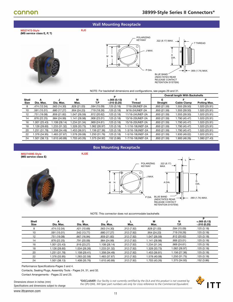
ADia. Max.
GDia. Max.
JDia. Max.
LMax.
MMax.
NT.P.
P+.005 (0.13)-.010 (0.25)
KJ2E
Performance Specifications-Pages 3 and 4.
Contacts, Sealing Plugs, Assembly Tools - Pages 24, 31, and 32.
Contact Arrangements - Pages 22 and 23.
Wall Mounting ReceptacleMS27472-Style(MS service class E, P, T)
ShellSize
ADia. Max.
JDia. Max.
MMax.
NT.P
TThread
EStraight
Overall length With BackshellsF
Cable ClampP
Potting Max.
P+.005 (0.13)-.010 (0.25)
KJ0
8
10
12
14
16
18
20
22
24
.474 (12.04)
.591 (15.01)
.751 (19.08)
.876 (22.25)
1.001 (25.43)
1.126 (28.60)
1.251 (31.78)
1.376 (34.95)
1.501 (38.13)
.563 (14.30)
.680 (17.27)
.859 (21.82)
.984 (24.99)
1.108 (28.14)
1.233 (31.32)
1.358 (34.49)
1.483 (37.67)
1.610 (40.89)
.828 (21.03)
.954 (24.23)
1.047 (26.59)
1.141 (28.98)
1.234 (31.34)
1.328 (33.73)
1.453 (36.91)
1.578 (39.08)
1.703 (43.26)
M N
P DIA.
A DIA.
T THREAD
.069 (1.74) MAX.
BLUE BAND (INDICTATES REAR RELEASE CONTACT RETENTION SYSTEM)
J MAX.
POLARIZING KEYWAY .322 (8.17) MAX.
.594 (15.09)
.719 (18.26)
.812 (20.62)
.906 (23.01)
.969 (24.61)
1.062 (26.97)
1.156 (27.36)
1.250 (31.76)
1.375 (34.92)
.125 (3.18)
.125 (3.18)
.125 (3.18)
.125 (3.18)
.125 (3.18)
.125 (3.18)
.125 (3.18)
.125 (3.18)
.152 (3.86)
7/16-28UNEF-2A
9/16-24UNEF-2A
11/16-24UNEF-2A
13/16-20UNEF-2A
15/16-20UNEF-2A
1-1/16-18UNEF-2A
1-3/16-18UNEF-2A
1-5/16-18UNEF-2A
1-7/16-18UNEF-2A
.850 (21.59)
.850 (21.59)
.850 (21.59)
.850 (21.59)
.850 (21.59)
.850 (21.59)
.850 (21.59)
.850 (21.59)
.850 (21.59)
1.555 (39.50)
1.555 (39.50)
1.555 (39.50)
1.790 (45.47)
1.790 (45.47)
1.790 (45.47)
1.790 (45.47)
1.930 (49.02)
1.900 (48.26)
1.020 (25.91)
1.020 (25.91)
1.020 (25.91)
1.020 (25.91)
1.020 (25.91)
1.020 (25.91)
1.020 (25.91)
1.020 (25.91)
1.080 (27.43)
NOTE: For backshell dimensions and configurations, see pages 29 and 31.
Box Mounting Receptacle
38999-Style Series II Connectors*
*DISCLAIMER: Our facility is not currently certified by the DLA and this product is not covered by the QPL/QML. Mil-Spec part numbers are only for cross reference to the Commercial Equivalent.*DISCLAIMER: Our facility is not currently certified by the DLA and this product is not covered by
the QPL/QML. Mil-Spec part numbers are only for cross reference to the Commercial Equivalent.
*DISCLAIMER: Our facility is not currently certified by the DLA and this product is not covered by the QPL/QML. Mil-Spec part numbers are only for cross reference to the Commercial Equivalent.

www.ittcannon.com
Dimensions shown in inches (mm) Specifications and dimensions subject to change
12
Box Mounting ReceptacleMS27513E(MS service class E)
KJ2R
Shell Size
8
10
12
14
16
18
20
22
24
.474 (12.04)
.591 (15.01)
.751 (19.08)
.876 (22.25)
1.001 (25.43)
1.126 (28.60)
1.251 (31.78)
1.376 (33.95)
1.501 (38.13)
.421 (10.69)
.542 (13.77)
.667 (16.94)
.791 (20.09)
.916 (23.27)
1.034 (26.26)
1.158 (29.41)
1.283 (32.59)
1.408 (35.76)
.563 (14.30)
.680 (17.27)
.859 (21.82)
.984 (24.99)
1.108 (28.14)
1.233 (31.32)
1.358 (34.49)
1.483 (27.67)
1.610 (40.89)
NOTE: This connector does not accommodate backshells
BLUE BAND (INDICATES REAR RELEASE CONTACT RETENTION SYSTEM)
.463 (11.76) MAX.
.322 (8.17) MAX.
L
P DIA.
POLARIZING KEYWAY
J MAX.
M N
.069 (1.74) MAX.
G DIA.
A DIA.
.312 (7.92)
.312 (7.92)
.312 (7.92)
.312 (7.92)
.312 (7.92)
.312 (7.92)
.312 (7.92)
.312 (7.92)
.312 (7.92)
.828 (21.03)
.954 (24.23)
1.047 (26.59)
1.141 (28.98)
1.234 (31.34)
1.328 (33.73)
1.453 (36.81)
1.578 (40.08)
1.703 (43.26)
.594 (15.09)
.719 (18.26)
.812 (20.62)
.906 (23.01)
.969 (24.61)
1.062 (26.97)
1.156 (27.36)
1.250 (31.75)
1.375 (34.93)
.125 (3.18)
.125 (3.18)
.125 (3.18)
.125 (3.18)
.125 (3.18)
.125 (3.18)
.125 (3.18)
.125 (3.18)
.152 (3.85)
A Dia. Max.
G Dia. Max.
J Dia. Max.
L Max.
M Max.
N T.P.
P +.005 (0.13) -.010 (0.25)
MS27513E-Style(MS service class E)
KJ2R
Shell Size
8
10
12
14
16
18
20
22
24
.474 (12.04)
.591 (15.01)
.751 (19.08)
.876 (22.25)
1.001 (25.43)
1.126 (28.60)
1.251 (31.78)
1.376 (33.95)
1.501 (38.13)
.421 (10.69)
.542 (13.77)
.667 (16.94)
.791 (20.09)
.916 (23.27)
1.034 (26.26)
1.158 (29.41)
1.283 (32.59)
1.408 (35.76)
.563 (14.30)
.680 (17.27)
.859 (21.82)
.984 (24.99)
1.108 (28.14)
1.233 (31.32)
1.358 (34.49)
1.483 (27.67)
1.610 (40.89)
NOTE: This connector does not accommodate backshells
BLUE BAND (INDICATES REAR RELEASE CONTACTRETENTION SYSTEM)
.463 (11.76) MAX.
.322 (8.17) MAX.
L
P DIA.
POLARIZING KEYWAY
J MAX.
M N
.069 (1.74) MAX.
G DIA.
A DIA.
.312 (7.92)
.312 (7.92)
.312 (7.92)
.312 (7.92)
.312 (7.92)
.312 (7.92)
.312 (7.92)
.312 (7.92)
.312 (7.92)
.828 (21.03)
.954 (24.23)
1.047 (26.59)
1.141 (28.98)
1.234 (31.34)
1.328 (33.73)
1.453 (36.81)
1.578 (40.08)
1.703 (43.26)
.594 (15.09)
.719 (18.26)
.812 (20.62)
.906 (23.01)
.969 (24.61)
1.062 (26.97)
1.156 (27.36)
1.250 (31.75)
1.375 (34.93)
.125 (3.18)
.125 (3.18)
.125 (3.18)
.125 (3.18)
.125 (3.18)
.125 (3.18)
.125 (3.18)
.125 (3.18)
.152 (3.85)
A Dia. Max.
G Dia. Max.
J Dia. Max.
L Max.
M Max.
N T.P.
P +.005 (0.13) -.010 (0.25)
Wall Mounting Receptacle
ShellSize
ADia. Max.
CDia. Max.
MMax.
NT.P
TThread
EStraight
Overall Length With Backshells
FCable Clamp
PPotting Max.
P+.005 (0.13)-.010 (0.25)
MS27497-Style(MS service class E, P, T)
8
10
12
14
16
18
20
22
24
.474 (12.04)
.591 (15.01)
.751 (19.08)
.876 (22.25)
1.001 (25.43)
1.126 (28.60)
1.251 (31.78)
1.376 (34.95)
1.501 (38.13)
.563 (14.30)
.680 (17.27)
.859 (21.82)
.984 (24.99)
1.108 (28.14)
1.233 (31.32)
1.358 (34.49)
1.483 (37.67)
1.610 (40.89)
.522 (13.26)
.639 (16.23)
.808 (20.52)
.935 (23.75)
1.058 (26.87)
1.183 (30.05)
1.308 (33.22)
1.433 (36.40)
1.568 (39.83)
.828 (21.03)
.954 (24.23)
1.047 (26.59)
1.141 (28.98)
1.234 (31.34)
1.328 (33.73)
1.453 (36.91)
1.578 (40.08)
1.703 (43.26)
BLUE BAND (INDICATES REAR RELEASE CONTACT RETENTION SYSTEM)
.477 (11.35) MAX.
.322 (8.17) MAX. T THREAD P DIA. POLARIZING KEYWAY
J DIA.
M N
.142 (3.01) MAX. PANEL THICKNESS (including mounting hardware)
.069 (1.74) MAX.
C DIA.
A DIA.
.594 (15.09)
.719 (18.26)
.812 (20.62)
.906 (23.01)
.969 (24.61)
1.062 (26.97)
1.156 (29.36)
1.250 (31.75)
1.375 (34.93)
.125 (3.18)
.125 (3.18)
.125 (3.18)
.125 (3.18)
.125 (3.18)
.125 (3.18)
.125 (3.18)
.125 (3.18)
.152 (3.86)
7/16-28UNEF-2A
9/16-24UNEF-2A
11/16-24UNEF-2A
13/16-20UNEF-2A
15/16-20UNEF-2A
1-1/16-18UNEF-2A
1-3/16-18UNEF-2A
1-5/16-18UNEF-2A
1-7/16-18UNEF-2A
.855 (21.72)
.855 (21.72)
.855 (21.72)
.855 (21.72)
.855 (21.72)
.855 (21.72)
.855 (21.72)
.855 (21.72)
.855 (21.72)
1.570 (39.88)
1.570 (39.88)
1.570 (39.88)
1.780 (45.21)
1.780 (45.21)
1.780 (45.21)
1.780 (45.21)
1.960 (49.78)
1.960 (49.78)
1.020 (25.91)
1.020 (25.91)
1.020 (25.91)
1.020 (25.91)
1.020 (25.91)
1.020 (25.91)
1.020 (25.91)
1.020 (25.91)
1.080 (27.43)
JDia. Max.
KJ3
NOTE: For backshell dimensions and configurations, see pages 29 and 31.
Performance Specifications-Pages 3 and 4.
Contacts, Sealing Plugs, Assembly Tools - Pages 24, 31, and 32.
Contact Arrangements - Pages 22 and 23.
38999-Style Series II Connectors*
*DISCLAIMER: Our facility is not currently certified by the DLA and this product is not covered by the QPL/QML. Mil-Spec part numbers are only for cross reference to the Commercial Equivalent.

www.ittcannon.com
Dimensions shown in inches (mm) Specifications and dimensions subject to change
13
Box Mounting Receptacle (Back Panel)MS27508E
Shell Size
A Dia. Max.
M Max.
N T.P
P +.005 (0.13) -.010 (0.25)
KJ5E
8
10
12
14
16
18
20
22
24
.474 (12.04)
.591 (15.01)
.751 (19.08)
.876 (22.25)
1.001 (25.42)
1.126 (28.60)
1.251 (31.77)
1.376 (34.95)
1.501 (38.13)
.563 (14.30)
.680 (17.27)
.859 (21.82)
.984 (24.99)
1.108 (28.14)
1.233 (31.32)
1.358 (34.49)
1.483 (37.67)
1.610 (40.89)
.828 (21.03)
.954 (24.23)
1.047 (26.59)
1.141 (28.98)
1.234 (31.24)
1.328 (33.73)
1.453 (36.91)
1.578 (40.08)
1.703 (43.66)
NOTE: This connector does not accommodate backshells
BLUE BAND (INDICATES REAR RELEASE CONTACT RETENTION SYSTEM)
.447 (11.35) MAX.
.322 (8.17) MAX.
L
P DIA. POLARIZING KEYWAY
J DIA.
M N
.069 (1.74) MAX.
G DIA.
K MAX. PANEL THICKNESS (including mounting hardware)
C A
.594 (15.09)
.719 (18.26)
.812 (20.62)
.906 (23.01)
.969 (24.61)
1.062 (26.97)
1.156 (29.36)
1.250 (31.75)
1.375 (34.92)
.125 (3.18)
.125 (3.18)
.125 (3.18)
.125 (3.18)
.125 (3.18)
.125 (3.18)
.125 (3.18)
.125 (3.18)
.152 (3.86)
J Dia. Max.
.147 (3.73)
.152 (3.86)
.152 (3.86)
.152 (3.86)
.152 (3.86)
.152 (3.86)
.179 (4.55)
.179 (4.55)
.169 (4.29)
K Max.
.185 (4.70)
.185 (4.70)
.185 (4.70)
.185 (4.70)
.185 (4.70)
.185 (4.70)
.185 (4.70)
.185 (4.70)
.185 (4.70)
L Max.
.421 (10.69)
.542 (13.77)
.667 (16.94)
.791 (20.09)
.916 (23.27)
1.034 (31.34)
1.158 (34.52)
1.283 (32.59)
1.408 (35.76)
G Dia. Max.
.522 (13.26)
.639 (16.23)
.808 (20.52)
.935 (23.75)
1.058 (26.87)
1.183 (30.05)
1.308 (33.22)
1.433 (36.40)
1.568 (39.83)
C Dia. Max.
(MS service class E) MS27508E-Style(MS service class E)
Shell Size
A Dia. Max.
M Max.
N T.P
P +.005 (0.13) -.010 (0.25)
KJ5E
8
10
12
14
16
18
20
22
24
.474 (12.04)
.591 (15.01)
.751 (19.08)
.876 (22.25)
1.001 (25.42)
1.126 (28.60)
1.251 (31.77)
1.376 (34.95)
1.501 (38.13)
.563 (14.30)
.680 (17.27)
.859 (21.82)
.984 (24.99)
1.108 (28.14)
1.233 (31.32)
1.358 (34.49)
1.483 (37.67)
1.610 (40.89)
.828 (21.03)
.954 (24.23)
1.047 (26.59)
1.141 (28.98)
1.234 (31.24)
1.328 (33.73)
1.453 (36.91)
1.578 (40.08)
1.703 (43.66)
NOTE: This connector does not accommodate backshells
BLUE BAND (INDICATES REAR RELEASE CONTACTRETENTION SYSTEM)
.447 (11.35) MAX.
.322 (8.17) MAX.
L
P DIA. POLARIZING KEYWAY
J DIA.
M N
.069 (1.74) MAX.
G DIA.
K MAX. PANEL THICKNESS (including mounting hardware)
C A
.594 (15.09)
.719 (18.26)
.812 (20.62)
.906 (23.01)
.969 (24.61)
1.062 (26.97)
1.156 (29.36)
1.250 (31.75)
1.375 (34.92)
.125 (3.18)
.125 (3.18)
.125 (3.18)
.125 (3.18)
.125 (3.18)
.125 (3.18)
.125 (3.18)
.125 (3.18)
.152 (3.86)
J Dia. Max.
.147 (3.73)
.152 (3.86)
.152 (3.86)
.152 (3.86)
.152 (3.86)
.152 (3.86)
.179 (4.55)
.179 (4.55)
.169 (4.29)
K Max.
.185 (4.70)
.185 (4.70)
.185 (4.70)
.185 (4.70)
.185 (4.70)
.185 (4.70)
.185 (4.70)
.185 (4.70)
.185 (4.70)
L Max.
.421 (10.69)
.542 (13.77)
.667 (16.94)
.791 (20.09)
.916 (23.27)
1.034 (31.34)
1.158 (34.52)
1.283 (32.59)
1.408 (35.76)
G Dia. Max.
.522 (13.26)
.639 (16.23)
.808 (20.52)
.935 (23.75)
1.058 (26.87)
1.183 (30.05)
1.308 (33.22)
1.433 (36.40)
1.568 (39.83)
C Dia. Max.
Box Mounting Receptacle (Back Panel)No MS part number KJ5R
NOTE: This connector does not accommodate backshells
BLUE BAND (INDICATES REAR RELEASE CONTACT RETENTION SYSTEM)
.447 (11.35) MAX.
.322 (8.17) MAX. .338 (8.58) MAX.
L
.069 (1.74) MAX.
G DIA.
C A
P DIA. POLARIZING KEYWAY
J DIA.
M N
K MAX. PANEL THICKNESS (including mounting hardware)
ShellSize
ADia. Max.
MMax.
NT.P
P+.005 (0.13)-.010 (0.25)
8
10
12
14
16
18
20
22
24
.474 (12.04)
.591 (15.01)
.751 (19.08)
.876 (22.25)
1.001 (25.42)
1.126 (28.60)
1.251 (31.77)
1.376 (34.95)
1.501 (38.13)
.563 (14.30)
.680 (17.27)
.859 (21.82)
.984 (24.99)
1.108 (28.14)
1.233 (31.32)
1.358 (34.49)
1.483 (37.67)
1.610 (40.89)
.828 (21.03)
.954 (24.23)
1.047 (26.59)
1.141 (28.98)
1.234 (31.24)
1.328 (33.73)
1.453 (36.91)
1.578 (40.08)
1.703 (43.66)
.594 (15.09)
.719 (18.26)
.812 (20.62)
.906 (23.01)
.969 (24.61)
1.062 (26.97)
1.156 (29.36)
1.250 (31.75)
1.375 (34.92)
.125 (3.18)
.125 (3.18)
.125 (3.18)
.125 (3.18)
.125 (3.18)
.125 (3.18)
.125 (3.18)
.125 (3.18)
.152 (3.86)
JDia. Max.
.147 (3.73)
.152 (3.86)
.152 (3.86)
.152 (3.86)
.152 (3.86)
.152 (3.86)
.179 (4.55)
.179 (4.55)
.169 (4.29)
KMax.
.185 (4.70)
.185 (4.70)
.185 (4.70)
.185 (4.70)
.185 (4.70)
.185 (4.70)
.185 (4.70)
.185 (4.70)
.185 (4.70)
LMax.
.421 (10.69)
.542 (13.77)
.667 (16.94)
.791 (20.09)
.916 (23.27)
1.034 (31.34)
1.158 (34.52)
1.283 (32.59)
1.408 (35.76)
GDia. Max.
.522 (13.26)
.639 (16.23)
.808 (20.52)
.935 (23.75)
1.058 (26.87)
1.183 (30.05)
1.308 (33.22)
1.433 (36.40)
1.568 (39.83)
CDia. Max.
Performance Specifications-Pages 3 and 4.
Contacts, Sealing Plugs, Assembly Tools - Pages 24, 31, and 32.
Contact Arrangements - Pages 22 and 23.
No MS part number KJ5R
NOTE: This connector does not accommodate backshells
BLUE BAND (INDICATES REAR RELEASE CONTACTRETENTION SYSTEM)
.447 (11.35) MAX.
.322 (8.17) MAX. .338 (8.58) MAX.
L
.069 (1.74) MAX.
G DIA.
C A
P DIA.POLARIZINGKEYWAY
J DIA.
M N
K MAX. PANEL THICKNESS (including mounting hardware)
ShellSize
ADia. Max.
MMax.
NT.P
P+.005 (0.13)-.010 (0.25)
8
10
12
14
16
18
20
22
24
.474 (12.04)
.591 (15.01)
.751 (19.08)
.876 (22.25)
1.001 (25.42)
1.126 (28.60)
1.251 (31.77)
1.376 (34.95)
1.501 (38.13)
.563 (14.30)
.680 (17.27)
.859 (21.82)
.984 (24.99)
1.108 (28.14)
1.233 (31.32)
1.358 (34.49)
1.483 (37.67)
1.610 (40.89)
.828 (21.03)
.954 (24.23)
1.047 (26.59)
1.141 (28.98)
1.234 (31.24)
1.328 (33.73)
1.453 (36.91)
1.578 (40.08)
1.703 (43.66)
.594 (15.09)
.719 (18.26)
.812 (20.62)
.906 (23.01)
.969 (24.61)
1.062 (26.97)
1.156 (29.36)
1.250 (31.75)
1.375 (34.92)
.125 (3.18)
.125 (3.18)
.125 (3.18)
.125 (3.18)
.125 (3.18)
.125 (3.18)
.125 (3.18)
.125 (3.18)
.152 (3.86)
JDia. Max.
.147 (3.73)
.152 (3.86)
.152 (3.86)
.152 (3.86)
.152 (3.86)
.152 (3.86)
.179 (4.55)
.179 (4.55)
.169 (4.29)
KMax.
.185 (4.70)
.185 (4.70)
.185 (4.70)
.185 (4.70)
.185 (4.70)
.185 (4.70)
.185 (4.70)
.185 (4.70)
.185 (4.70)
LMax.
.421 (10.69)
.542 (13.77)
.667 (16.94)
.791 (20.09)
.916 (23.27)
1.034 (31.34)
1.158 (34.52)
1.283 (32.59)
1.408 (35.76)
GDia. Max.
.522 (13.26)
.639 (16.23)
.808 (20.52)
.935 (23.75)
1.058 (26.87)
1.183 (30.05)
1.308 (33.22)
1.433 (36.40)
1.568 (39.83)
CDia. Max.
Performance Specifications-Pages A-7, A-8.
Contacts, Sealing Plugs, Assembly Tools - Pages A-26, A-32, A-33.
Contact Arrangements - Pages A-24, A-25.
38999-Style Series II Connectors*
*DISCLAIMER: Our facility is not currently certified by the DLA and this product is not covered by the QPL/QML. Mil-Spec part numbers are only for cross reference to the Commercial Equivalent.

www.ittcannon.com
Dimensions shown in inches (mm) Specifications and dimensions subject to change
14
Straight Plug
MS27473-Style(MS service class E, P, T)
ShellSize
ADia. Max.
KJ6
8
10
12
14
16
18
20
22
24
.485 (12.32)
.606 (15.39)
.765 (19.43)
.890 (22.61)
1.014 (25.76)
1.140 (28.96)
1.264 (32.11)
1.389 (35.28)
1.514 (38.46)
GDia. Max.
.749 (19.02)
.858 (21.79)
1.030 (26.16)
1.155 (29.34)
1.280 (32.51)
1.405 (35.69)
1.530 (38.86)
1.640 (40.66)
1.765 (44.83)
PDia. Max..630 (16.00)
.752 (19.10)
.925 (23.50)
1.050 (26.67)
1.172 (29.77)
1.304 (33.12)
1.435 (36.45)
1.560 (39.62)
1.688 (42.88)
TThread
EStraight
FCable Clamp
Overall Length With BackshellsP
Potting Max.7/16-28UNEF-2A
9/16-24UNEF-2A
11/16-24UNEF-2A
13/16-20UNEF-2A
15/16-20UNEF-2A
1-1/16-18UNEF-2A
1-3/16-18UNEF-2A
1-5/16-18UNEF-2A
1-7/16-18UNEF-2A
1.026 (26.06)
1.026 (26.06)
1.026 (26.06)
1.026 (26.06)
1.026 (26.06)
1.026 (26.06)
1.026 (26.06)
1.026 (26.06)
1.104 (28.04)
1.555 (39.50)
1.555 (39.50)
1.555 (39.50)
1.790 (45.47)
1.790 (45.47)
1.790 (45.47)
1.790 (45.47)
1.930 (49.02)
1.930 (49.02)
1.020 (25.91)
1.020 (25.91)
1.020 (25.91)
1.020 (25.91)
1.020 (25.91)
1.020 (25.91)
1.020 (25.91)
1.020 (25.91)
1.080 (27.43)
BLUE BAND (INDICATES REAR RELEASE CONTACT RETENTION SYSTEM)
POLARIZING KEYWAY
G DIA.
P DIA.
A DIA.
T THREAD
NOTE: For backshell dimensions and configurations, see pages 29 and 31.
Straight Plug GroundedMS27484(MS service class E, P, T)
KJG6
ShellSize
ADia. Max.
8
10
12
14
16
18
20
22
24
.485 (12.32)
.606 (15.39)
.765 (19.43)
.890 (22.61)
1.014 (25.76)
1.140 (28.96)
1.264 (32.11)
1.389 (35.28)
1.514 (38.46)
GDia. Max.
.749 (19.02)
.858 (21.79)
1.030 (26.16)
1.155 (29.34)
1.280 (32.51)
1.405 (35.69)
1.530 (38.86)
1.640 (40.66)
1.765 (44.83)
PDia. Max.
.630 (16.00)
.752 (19.10)
.925 (23.50)
1.050 (26.67)
1.172 (29.77)
1.304 (33.12)
1.435 (36.45)
1.560 (39.62)
1.688 (42.88)
TThread
EStraight
FCable Clamp
Overall Length With BackshellsP
Potting Max.7/16-28UNEF-2A
9/16-24UNEF-2A
11/16-24UNEF-2A
13/16-20UNEF-2A
15/16-20UNEF-2A
1-1/16-18UNEF-2A
1-3/16-18UNEF-2A
1-5/16-18UNEF-2A
1-7/16-18UNEF-2A
1.026 (26.06)
1.026 (26.06)
1.026 (26.06)
1.026 (26.06)
1.026 (26.06)
1.026 (26.06)
1.026 (26.06)
1.026 (26.06)
1.104 (28.04)
1.555 (39.50)
1.555 (39.50)
1.555 (39.50)
1.790 (45.47)
1.790 (45.47)
1.790 (45.47)
1.790 (45.47)
1.930 (49.02)
1.930 (49.02)
1.020 (25.91)
1.020 (25.91)
1.020 (25.91)
1.020 (25.91)
1.020 (25.91)
1.020 (25.91)
1.020 (25.91)
1.020 (25.91)
1.080 (27.43)
BLUE BAND (INDICATES REAR RELEASE CONTACTRETENTION SYSTEM)
POLARIZING KEYWAY
G DIA.
P DIA.
A DIA.
T THREAD
NOTE: For backshell dimensions and configurations, see pages 29 and 31.
Performance Specifications-Pages 3 and 4.
Contacts, Sealing Plugs, Assembly Tools - Pages 24, 31, and 32.
Contact Arrangements - Pages 22 and 23.
MS27484-Style(MS service class E, P, T)
KJG6
ShellSize
ADia. Max.
8
10
12
14
16
18
20
22
24
.485 (12.32)
.606 (15.39)
.765 (19.43)
.890 (22.61)
1.014 (25.76)
1.140 (28.96)
1.264 (32.11)
1.389 (35.28)
1.514 (38.46)
GDia. Max.
.749 (19.02)
.858 (21.79)
1.030 (26.16)
1.155 (29.34)
1.280 (32.51)
1.405 (35.69)
1.530 (38.86)
1.640 (40.66)
1.765 (44.83)
PDia. Max.
.630 (16.00)
.752 (19.10)
.925 (23.50)
1.050 (26.67)
1.172 (29.77)
1.304 (33.12)
1.435 (36.45)
1.560 (39.62)
1.688 (42.88)
TThread
EStraight
FCable Clamp
Overall Length With Backshells
PPotting Max.
7/16-28UNEF-2A
9/16-24UNEF-2A
11/16-24UNEF-2A
13/16-20UNEF-2A
15/16-20UNEF-2A
1-1/16-18UNEF-2A
1-3/16-18UNEF-2A
1-5/16-18UNEF-2A
1-7/16-18UNEF-2A
1.026 (26.06)
1.026 (26.06)
1.026 (26.06)
1.026 (26.06)
1.026 (26.06)
1.026 (26.06)
1.026 (26.06)
1.026 (26.06)
1.104 (28.04)
1.555 (39.50)
1.555 (39.50)
1.555 (39.50)
1.790 (45.47)
1.790 (45.47)
1.790 (45.47)
1.790 (45.47)
1.930 (49.02)
1.930 (49.02)
1.020 (25.91)
1.020 (25.91)
1.020 (25.91)
1.020 (25.91)
1.020 (25.91)
1.020 (25.91)
1.020 (25.91)
1.020 (25.91)
1.080 (27.43)
BLUE BAND (INDICATES REAR RELEASE CONTACT RETENTION SYSTEM)
POLARIZING KEYWAY
G DIA.
P DIA.
A DIA.
T THREAD
NOTE: For backshell dimensions and configurations, see pages A-30, A-32.
Performance Specifications-Pages A-7, A-8.
Contacts, Sealing Plugs, Assembly Tools - Pages A-26, A-32, A-33.
Contact Arrangements - Pages A-24, A-25.
38999-Style Series II Connectors*
*DISCLAIMER: Our facility is not currently certified by the DLA and this product is not covered by the QPL/QML. Mil-Spec part numbers are only for cross reference to the Commercial Equivalent.

www.ittcannon.com
Dimensions shown in inches (mm) Specifications and dimensions subject to change
15
Jam Nut Receptacle
MS27474-Style(MS service class E, P, T)
ShellSize
CDia. Max.
KJ7
8
10
12
14
16
18
20
22
24
.474 (12.04)
.591 (15.01)
.751 (19.08)
.876 (22.25)
1.001 (25.43)
1.126 (28.60)
1.251 (31.78)
1.376 (33.95)
1.501 (38.13)
DMax.
GMax.
JMax.
.818 (20.78)
.942 (23.93)
1.066 (27.08)
1.191 (30.25)
1.321 (33.55)
1.441 (36.60)
1.566 (39.78)
1.691 (42.95)
1.816 (46.13)
.145 (3.68)
.145 (3.68)
.145 (3.68)
.145 (3.68)
.145 (3.68)
.145 (3.68)
.171 (4.34)
.171 (4.34)
.171 (4.34)
.563 (14.30)
.680 (17.27)
.859 (21.82)
.984 (24.99)
1.108 (28.14)
1.233 (31.32)
1.358 (34.49)
1.483 (37.67)
1.610 (40.89)
PMax.
RMax. Hex.
SDia. Max.
.443 (11.25)
.443 (11.25)
.443 (11.25)
.443 (11.25)
.443 (11.25)
.443 (11.25)
.469 (11.91)
.469 (11.91)
.469 (11.91)
1.079 (27.41)
1.205 (30.61)
1.329 (33.76)
1.455 (36.96)
1.579 (40.11)
1.705 (43.31)
1.829 (46.46)
2.017 (51.23)
2.142 (54.41)
1.381 (35.08)
1.506 (38.25)
1.631 (41.43)
1.756 (44.60)
1.944 (49.38)
2.022 (51.36)
2.147 (54.53)
2.271 (57.68)
2.396 (60.86)
TThread
VThread
EStraight
FCable Clamp
Overall length With BackshellsP
Potting Max.7/16-28UNEF-2A
9/16-24UNEF-2A
11/16-24UNEF-2A
13/16-20UNEF-2A
1-15/16-20UNEF-2A
1-1/16-18UNEF-2A
1-3/16-18UNEF-2A
1-5/16-18UNEF-2A
1-7/16-18UNEF-2A
7/8-20UNEF-2A
1-20UNEF-2A
1-1/8-18UNEF-2A
1-1/4-18UNEF-2A
1-3/8-18UNEF-2A
1-1/2-18UNEF-2A
1-5/8-18UNEF-2A
1-3/4-18UNS-2A
1-7/8-18UNS-2A
.840 (21.34)
.840 (21.34)
.840 (21.34)
.840 (21.34)
.840 (21.34)
.840 (21.34)
.840 (21.34)
.840 (21.34)
.860 (21.84)
1.555 (39.50)
1.555 (39.50)
1.555 (39.50)
1.790 (45.47)
1.790 (45.47)
1.790 (45.47)
1.790 (45.47)
1.930 (49.02)
1.900(48.26)
1.020 (25.91)
1.020 (25.91)
1.020 (25.91)
1.020 (25.91)
1.020 (25.91)
1.020 (25.91)
1.020 (25.91)
1.020 (25.91)
1.080 (27.43)
V THREAD
T THREAD
BLUE BAND (INDICATES REAR RELEASE COTACT RETENTION SYSTEM)
.105 (2.66) MAX.
.109 (2.77) MAX. PANEL THICKNESS
R
S DIA.
J DIA.
D MOUNTING FLAT
POLARIZING KEYWAY
C
G
P
NOTE: For backshell dimensions and configurations, see pages 29 and 31.
Performance Specifications-Pages 3 and 4.
Contacts, Sealing Plugs, Assembly Tools - Pages 24, 31, and 32.
Contact Arrangements - Pages 22 and 23.
Panel Cutouts
Flange Mounted Receptacle Jam Nut Receptacle
ShellSize
ADia.
PDia.
Mfg.Screw
ShellSize
ADia.
BDia.R
8
10
12
14
16
18
20
22
24
.610 (15.49)
.734 (18.64)
.860 (21.84)
.985 (25.02)
1.110 (28.19)
1.234 (31.34)
1.360 (35.54)
1.484 (37.69)
1.611 (40.92)
.125 (3.18)
.125 (3.18)
.125 (3.18)
.125 (3.18)
.125 (3.18)
.125 (3.18)
.125 (3.18)
.125 (3.18)
.152 (3.86)
.594 (15.09)
.719 (18.26)
.812 (20.62)
.906 (23.01)
.969 (24.61)
1.062 (26.97)
1.156 (29.36)
1.250 (31.75)
1.375 (34.93)
#4
#4
#4
#4
#4
#4
#4
#4
#6
8
10
12
14
16
18
20
22
24
.885 (22.48)
1.010 (25.65)
1.135 (28.82)
1.260 (32.00)
1.385 (35.18)
1.510 (38.35)
1.635 (41.53)
1.760 (44.70)
1.885 (47.88)
.830 (21.08)
.955 (24.26)
1.085 (27.56)
1.210 (30.73)
1.335 (33.91)
1.460 (37.08)
1.585 (40.26)
1.710 (43.43)
1.835 (46.61)
P +_ .005 (0.13)4 HOLES
+.010 (0.25)-.000 (0.00)
+.010 (0.25)-.000 (0.00)
+.000 (0.00)-.010 (0.25)
B
A
R(T.P.)
A
38999-Style Series II Connectors*
*DISCLAIMER: Our facility is not currently certified by the DLA and this product is not covered by the QPL/QML. Mil-Spec part numbers are only for cross reference to the Commercial Equivalent.

www.ittcannon.com
Dimensions shown in inches (mm) Specifications and dimensions subject to change
16
How To Order
Military Nomenclature D38999-Style 20 F C 35 A N
CONNECTOR TYPE
SHELL STYLE
SHELL SIZE
CONTACT ARRANGEMENT
CONTACT STYLE
POLARIZING POSITION
MilitaryDesignationA
9
B
11
C
13
D
15
E
17
F
19
G
21
H
23
J
25 CannonDesignation
SHELL SIZE
SERVICE CLASS(HARDWARE FINISH)
KJB 0 T 13 F 35 P N L
MilitaryDesignation
9
A
11
B
13
C
15
D
17
E
19
F
21
G
23
H
25
J
CannonDesignation
SERIES PREFIX
SHELL STYLE
CLASS
SHELL SIZE
HARDWARE FINISH
CONTACT ARRANGEMENT
CONTACT STYLE
POLARIZING POSITION
MODIFICATION CODE
SHELL SIZE
Cannon Nomenclature
SERIES PREFIXKJA/KJB* - Series III - Scoop proof,
threaded coupling
SHELL STYLE0 - Wall mount receptacle5 - Box mount receptacle*6 - Straight plug7 - Jam nut receptacle
CLASST - Environment-resistant (without rear accessory)
* Consult factory for availability
HARDWARE FINISHF - Electroless nickel, - 85ºF to +392ºF
(-65ºC to +200ºC)G - Electroless nickel plated. Space Grade.W - Olive drab cadmium over electroless nickel
plate, -85ºF to +347ºF (-65ºC to +175ºC)Z - Zinc Nickel, Black- - (Dash) When using a finish modification code
CONTACT ARRANGEMENTS See pages 22 and 23.
CONTACT STYLEP -Pin contactsS -Socket contacts
POLARIZING POSITIONN (normal) A, B, C, D, E. See page 19.
MODIFICATION CODE L - Less contacts, not stamped on connector16 - Outgassed
NASA space graded connector17 - Clinch Nuts installed
(4-40 Size 9-21, 6-32 Size 23-25) 27 - Outgassed, standard connector A296 Black Zinc Cobalt, RoHS Compliant
See page 26 for ordering PC Standoff Contacts using modification codes.
CONNECTOR TYPED38999-Style Series III
SHELL STYLED38999/20-Style - Wall mount receptacle D38999/24-Style - Jam nut receptacle D38999/26-Style - Straight Plug, Grounded
SERVICE CLASS(Hardware Finish)F - Electroless nickel - 85ºF to +392ºF
(-65ºC to +200ºC)G - Electroless nickel plated. Space Grade.W - Olive drab cadmium over electroless nickel
plate, -85ºF to +347ºF (-65ºC to +175ºC)
CONTACT ARRANGEMENT See pages 22, 23.
CONTACT STYLEP - Pin contactsS - Socket contactA - Less Pin contacts*B - Less Socket contact*
* Used only when other than power contacts are tobe installed (i,e., shielded, thermocouple, etc.)
POLARIZING POSITIONN (normal), A, B, C, D, E. See page 19.
Note: To order MS connectors less standard power contacts, purchase order must state “Less Contacts”.
38999-Style Series III Connectors*
DISCLAIMER: Our facility is not currently certified by the DLA and this product is not covered by the QPL/QML. Mil-Spec part numbers are only for cross reference to the Commercial Equivalent.
*DISCLAIMER: Our facility is not currently certified by the DLA and this product is not covered by the QPL/QML. Mil-Spec part numbers are only for cross reference to the Commercial Equivalent.
www.ittcannon.com
Dimensions shown in inches (mm) Specifications and dimensions subject to change
17
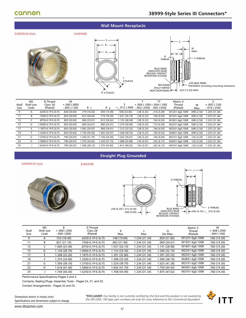
38999-Style Series III Connectors*
Wall Mount Receptacle
Straight Plug Grounded
D38999/20-Style
ShellSize
MSShell size
Code
B ThreadClass 2A(Plated)
M+.000 (.000)-.005 (.130)
T+.004 (.100)-.002 (.050)
TT+.004 (.100)-.002 (.050)
Z+.005 (.130)-.010 (.250)
Metric VThread(Plated)
WMax.
S+_.012 (.300)R 1 R 2
R 1
R 2
KJA0/KJB0
9
11
13
15
17
19
21
23
25
A
B
C
D
E
F
G
H
J
.6250-0.1P-0.3L-TS
.7500-0.1P-0.3L-TS
.8750-0.1P-0.3L-TS
1.0000-0.1P-0.3L-TS
1.1875-0.1P-0.3L-TS
1.2500-0.1P-0.3L-TS
1.3750-0.1P-0.3L-TS
1.5000-0.1P-0.3L-TS
1.6250-0.1P-0.3L-TS
.820 (20.83)
.820 (20.83)
.820 (20.83)
.820 (20.83)
.820 (20.83)
.820 (20.83)
.790 (20.07)
.790 (20.07)
.790 (20.07)
.719 (18.26)
.812 (20.62)
.906 (23.01)
.969 (24.61)
1.062 (26.97)
1.156 (29.36)
1.250 (31.75)
1.375 (34.92)
1.500 (38.10)
.594 (15.09)
.719 (18.26)
.812 (20.62)
.906 (23.01)
.969 (24.61)
1.062 (26.97)
1.156 (29.36)
1.250 (31.75)
1.375 (34.92)
.938 (23.83)
1.031 (26.19)
1.125 (28.58)
1.219 (30.96)
1.312 (33.32)
1.438 (36.53)
1.562 (39.67)
1.688 (42.88)
1.812 (46.02)
.128 (3.25)
.128 (3.25)
.128 (3.25)
.128 (3.25)
.128 (3.25)
.128 (3.25)
.128 (3.25)
.154 (3.91)
.154 (3.91)
.216 (5.49)
.194 (4.93)
.194 (4.93)
.173 (4.39)
.194 (4.93)
.194 (4.93)
.194 (4.93)
.242 (6.15)
.242 (6.15)
M12X1-6g0.100R
M15X1-6g0.100R
M18X1-6g0.100R
M22X1-6g0.100R
M25X1-6g0.100R
M28X1-6g0.100R
M31X1-6g0.100R
M34X1-6g0.100R
M37X1-6g0.100R
.098 (2.50)
.098 (2.50)
.098 (2.50)
.098 (2.50)
.098 (2.50)
.098 (2.50)
.126 (3.20)
.126 (3.20)
.126 (3.20)
1.235 (31.36)
1.235 (31.36)
1.235 (31.36)
1.235 (31.36)
1.235 (31.36)
1.235 (31.36)
1.235 (31.36)
1.235 (31.36)
1.235 (31.36)
Z
WMAX.
V THREAD
MB
THREAD
S
T4 PLACES
.520 (13.20) MAX
BLUE BAND(INDICATES REAR
RELEASE CONTACTRETENTION SYSTEM)
TT 4 PLACES
RED BAND(FULLY MATED
INDICTAOR BAND)
.230 MAX PANEL THICKNESS (including mounting hardware)
D38999/20
ShellSize
MSShell size
Code
B ThreadClass 2A(Plated)
M+.000 (.000)-.005 (.130)
T+.004 (.100)-.002 (.050)
TT+.004 (.100)-.002 (.050)
Z+.005 (.130)-.010 (.250)
Metric VThread(Plated)
WMax.
S+_.012 (.300)R 1 R 2
R 1
R 2
KJA0/KJB0
9
11
13
15
17
19
21
23
25
A
B
C
D
E
F
G
H
J
.6250-0.1P-0.3L-TS
.7500-0.1P-0.3L-TS
.8750-0.1P-0.3L-TS
1.0000-0.1P-0.3L-TS
1.1875-0.1P-0.3L-TS
1.2500-0.1P-0.3L-TS
1.3750-0.1P-0.3L-TS
1.5000-0.1P-0.3L-TS
1.6250-0.1P-0.3L-TS
.820 (20.83)
.820 (20.83)
.820 (20.83)
.820 (20.83)
.820 (20.83)
.820 (20.83)
.790 (20.07)
.790 (20.07)
.790 (20.07)
.719 (18.26)
.812 (20.62)
.906 (23.01)
.969 (24.61)
1.062 (26.97)
1.156 (29.36)
1.250 (31.75)
1.375 (34.92)
1.500 (38.10)
.594 (15.09)
.719 (18.26)
.812 (20.62)
.906 (23.01)
.969 (24.61)
1.062 (26.97)
1.156 (29.36)
1.250 (31.75)
1.375 (34.92)
.938 (23.83)
1.031 (26.19)
1.125 (28.58)
1.219 (30.96)
1.312 (33.32)
1.438 (36.53)
1.562 (39.67)
1.688 (42.88)
1.812 (46.02)
.128 (3.25)
.128 (3.25)
.128 (3.25)
.128 (3.25)
.128 (3.25)
.128 (3.25)
.128 (3.25)
.154 (3.91)
.154 (3.91)
.216 (5.49)
.194 (4.93)
.194 (4.93)
.173 (4.39)
.194 (4.93)
.194 (4.93)
.194 (4.93)
.242 (6.15)
.242 (6.15)
M12X1-6g0.100R
M15X1-6g0.100R
M18X1-6g0.100R
M22X1-6g0.100R
M25X1-6g0.100R
M28X1-6g0.100R
M31X1-6g0.100R
M34X1-6g0.100R
M37X1-6g0.100R
.098 (2.50)
.098 (2.50)
.098 (2.50)
.098 (2.50)
.098 (2.50)
.098 (2.50)
.126 (3.20)
.126 (3.20)
.126 (3.20)
1.235 (31.36)
1.235 (31.36)
1.235 (31.36)
1.235 (31.36)
1.235 (31.36)
1.235 (31.36)
1.235 (31.36)
1.235 (31.36)
1.235 (31.36)
Z
WMAX.
V THREAD
MB
THREAD
S
T4 PLACES
.520 (13.20) MAX
BLUE BAND(INDICATES REAR
RELEASE CONTACTRETENTION SYSTEM)
TT 4 PLACES
RED BAND(FULLY MATED
INDICTAOR BAND)
.230 MAX PANEL THICKNESS (including mounting hardware)
KJA6/KJB6D38999/26-Style
ShellSize
MSShell size
Code
B+.008 (.200)-.000 (.000)
W+.008 (.200)-.004 (.100)
D ThreadClass 2B(Plated)
KMax.
LMax.
QDia Max.
91113151719212325
ABCDEFGHJ
.724 (18.40)
.831 (21.10)1.000 (25.40)1.130 (28.70)1.268 (32.20)1.374 (34.90)1.500 (38.10)1.618 (41.40)1.744 (44.30)
.6250-0.1P-0.3L-TS
.7500-0.1P-0.3L-TS
.8750-0.1P-0.3L-TS1.0000-0.1P-0.3L-TS1.1875-0.1P-0.3L-TS1.2500-0.1P-0.3L-TS1.3750-0.1P-0.3L-TS1.5000-0.1P-0.3L-TS1.6250-0.1P-0.3L-TS
QD THREAD
W
L
B
V THREAD
.185 (4.70) +_ .016 (0.40)BLUE BAND
(INDICATES REARRELEASE CONTACT
RETENTION SYSTEMS
K
.244 (6.20)+.012 (0.30)-.000 (0.00)
.748 (19.00)
.862 (21.90)1.027 (26.10)1.153 (29.30)1.291 (32.80)1.398 (35.50)1.524 (38.70)1.642 (41.70)1.768 (44.90)
1.234 (31.34)1.234 (31.34)1.234 (31.34)1.234 (31.34)1.234 (31.34)1.234 (31.34)1.234 (31.34)1.234 (31.34)1.234 (31.34)
.859 (21.82)
.969 (24.61)1.141 (28.98)1.266 (32.16)1.391 (35.53)1.500 (38.10)1.625 (41.28)1.750 (44.45)1.875 (47.62)
.760 (19.30)
.760 (19.30)
.760 (19.30)
.760 (19.30)
.760 (19.30)
.760 (19.30)
.760 (19.30)
.760 (19.30)
.760 (19.30)
Metric VThread(Plated)
M12X1-6g0.100RM15X1-6g0.100RM18X1-6g0.100RM22X1-6g0.100RM25X1-6g0.100RM28X1-6g0.100RM31X1-6g0.100RM34X1-6g0.100RM37X1-6g0.100R
Performance Specifications-Pages 3 and 4.
Contacts, Sealing Plugs, Assembly Tools - Pages 24, 31, and 32.
Contact Arrangements - Pages 22 and 23.
*DISCLAIMER: Our facility is not currently certified by the DLA and this product is not covered by the QPL/QML. Mil-Spec part numbers are only for cross reference to the Commercial Equivalent.*DISCLAIMER: Our facility is not currently certified by the DLA and this product is not covered by
the QPL/QML. Mil-Spec part numbers are only for cross reference to the Commercial Equivalent.
*DISCLAIMER: Our facility is not currently certified by the DLA and this product is not covered by the QPL/QML. Mil-Spec part numbers are only for cross reference to the Commercial Equivalent.

www.ittcannon.com
Dimensions shown in inches (mm) Specifications and dimensions subject to change
18
Jam Nut Receptacle
Panel Cutouts
D38999/24-Style
ShellSize
MSShell size
Code
M+.005 (.130)-.004 (.100)
P+.016 (.410)-.004 (.100)
Metric RThread(Plated)S
Z+.005 (.130)-.040 (.100)
C+.004 (.100)-.010 (.250)
A +.010 (.250)-.005 (.130)
B ThreadClass 2A(Plated)
Metric VThread(Plated)
KJA7/KJB7
9
11
13
15
17
19
21
23
25
A
B
C
D
E
F
G
H
J
.104 (2.64)
.104 (2.64)
.104 (2.64)
.104 (2.64)
.104 (2.64)
.135 (3.43)
.135 (3.43)
.135 (3.43)
.135 (3.43)
.6250-0.1P-0.3L-TS
.7500-0.1P-0.3L-TS
.8750-0.1P-0.3L-TS
1.0000-0.1P-0.3L-TS
1.1875-0.1P-0.3L-TS
1.2500-0.1P-0.3L-TS
1.3750-0.1P-0.3L-TS
1.5000-0.1P-0.3L-TS
1.6250-0.1P-0.3L-TS
.651 (16.53)
.751 (19.07)
.938 (23.82)
1.062 (26.97)
1.187 (30.15)
1.312 (33.32)
1.437 (36.50)
1.562 (39.67)
1.687 (42.85)
1.243 (31.57)
1.243 (31.57)
1.243 (31.57)
1.243 (31.57)
1.243 (31.57)
1.243 (31.57)
1.243 (31.57)
1.243 (31.57)
1.243 (31.57)
.871 (22.12)
.871 (22.12)
.878 (22.30)
.878 (22.30)
.878 (22.30)
.878 (22.30)
.878 (22.30)
.878 (22.30)
.878 (22.30)
.555 (14.10)
.555 (14.10)
.563 (14.30)
.563 (14.30)
.563 (14.30)
.563 (14.30)
.563 (14.30)
.563 (14.30)
.563 (14.30)
1.062 (26.97)
1.250 (31.75)
1.375 (34.92)
1.500 (38.10)
1.625 (41.28)
1.812 (46.02)
1.938 (49.23)
2.062 (52.37)
2.188 (55.38)
M12X1-6g0.100R
M15X1-6g0.100R
M18X1-6g0.100R
M22X1-6g0.100R
M25X1-6g0.100R
M28X1-6g0.100R
M31X1-6g0.100R
M34X1-6g0.100R
M37X1-6g0.100R
M17X1-6g0.100R
M20X1-6g0.100R
M25X1-6g0.100R
M28X1-6g0.100R
M32X1-6g0.100R
M35X1-6g0.100R
M38X1-6g0.100R
M41X1-6g0.100R
M44X1-6g0.100R
V THREADR THREAD
.520 (13.2) MAX..062 (1.57) MIN./.125 (3.18) MAX.PANEL THICKNESS
S
Z
A
M
PB
THREAD
S CFLAT
BLUE BAND(INDICATES REARRELEASE CONTACTRETENTION SYSTEM)
RED BAND(FULLY MATED
INDICATOR BAND)
Performance Specifications-Pages A-7, A-8.
Contacts, Sealing Plugs, Assembly Tools - Pages A-26, A-32, A-33.
Contact Arrangements - Pages A-24, A-25.
D38999/24
ShellSize
MSShell size
Code
M+.005 (.130)-.004 (.100)
P+.016 (.410)-.004 (.100)
Metric RThread(Plated)S
Z+.005 (.130)-.040 (.100)
C+.004 (.100)-.010 (.250)
A +.010 (.250)-.005 (.130)
B ThreadClass 2A(Plated)
Metric VThread(Plated)
KJA7/KJB7
9
11
13
15
17
19
21
23
25
A
B
C
D
E
F
G
H
J
.104 (2.64)
.104 (2.64)
.104 (2.64)
.104 (2.64)
.104 (2.64)
.135 (3.43)
.135 (3.43)
.135 (3.43)
.135 (3.43)
.6250-0.1P-0.3L-TS
.7500-0.1P-0.3L-TS
.8750-0.1P-0.3L-TS
1.0000-0.1P-0.3L-TS
1.1875-0.1P-0.3L-TS
1.2500-0.1P-0.3L-TS
1.3750-0.1P-0.3L-TS
1.5000-0.1P-0.3L-TS
1.6250-0.1P-0.3L-TS
.651 (16.53)
.751 (19.07)
.938 (23.82)
1.062 (26.97)
1.187 (30.15)
1.312 (33.32)
1.437 (36.50)
1.562 (39.67)
1.687 (42.85)
1.243 (31.57)
1.243 (31.57)
1.243 (31.57)
1.243 (31.57)
1.243 (31.57)
1.243 (31.57)
1.243 (31.57)
1.243 (31.57)
1.243 (31.57)
.871 (22.12)
.871 (22.12)
.878 (22.30)
.878 (22.30)
.878 (22.30)
.878 (22.30)
.878 (22.30)
.878 (22.30)
.878 (22.30)
.555 (14.10)
.555 (14.10)
.563 (14.30)
.563 (14.30)
.563 (14.30)
.563 (14.30)
.563 (14.30)
.563 (14.30)
.563 (14.30)
1.062 (26.97)
1.250 (31.75)
1.375 (34.92)
1.500 (38.10)
1.625 (41.28)
1.812 (46.02)
1.938 (49.23)
2.062 (52.37)
2.188 (55.38)
M12X1-6g0.100R
M15X1-6g0.100R
M18X1-6g0.100R
M22X1-6g0.100R
M25X1-6g0.100R
M28X1-6g0.100R
M31X1-6g0.100R
M34X1-6g0.100R
M37X1-6g0.100R
M17X1-6g0.100R
M20X1-6g0.100R
M25X1-6g0.100R
M28X1-6g0.100R
M32X1-6g0.100R
M35X1-6g0.100R
M38X1-6g0.100R
M41X1-6g0.100R
M44X1-6g0.100R
V THREADR THREAD
.520 (13.2) MAX..062 (1.57) MIN./.125 (3.18) MAX.PANEL THICKNESS
S
Z
A
M
PB
THREAD
S CFLAT
BLUE BAND(INDICATES REARRELEASE CONTACTRETENTION SYSTEM)
RED BAND(FULLY MATED
INDICATOR BAND)
Performance Specifications-Pages 3 and 4.
Contacts, Sealing Plugs, Assembly Tools - Pages 24, 31, and 32.
Contact Arrangements - Pages 22 and 23.
Wall Mounted Receptacle Jam Nut Receptacle
ShellSize
R(TP)
ØT±.050 (.13)
9
11
13
15
17
19
21
23
25
.516 (13.11)
.625 (15.88)
.750 (19.05)
.906 (23.01)
1.016 (25.81)
1.141 (28.98)
1.266 (36.16)
1.375 (34.92)
1.484 (37.69)
.656 (16.66)
.796 (20.22)
.922 (23.42)
1.047 (26.59)
1.219 (30.96)
1.297 (32.94)
1.422 (36.12)
1.547 (39.29)
1.672 (42.47)
.128 (3.25)
.128 (3.25)
.128 (3.25)
.128 (3.25)
.128 (3.25)
.128 (3.25)
.128 (3.25)
.154 (391)
.150 (3.81)
.719 (18.26)
.812 (20.62)
.906 (23.01)
.969 (24.61)
1.062 (26.97)
1.156 (29.36)
1.250 (31.75)
1.375 (34.92)
1.500 (38.10)
B+.000 (.00)*-.010 (.25)
.657 (16.70)
.771 (19.58)
.955 (24.26)
1.085 (27.56)
1.210 (30.73)
1.335 (33.91)
1.460 (37.08)
1.585 (40.26)
1.710 (43.43)
A+.010 (.25)-.000 (.00).693 (17.6)
.825 (20.96)
1.010 (25.65)
1.135 (28.83)
1.260 (32.00)
1.385 (35.18)
1.510 (38.35)
1.635 (41.53)
1.760 (44.70)
* For Dimension B, Shell Size 9 only, tolerance is ±.004 (.10)
B
A
ØH1(Min.)
ØH2(Min.)
38999-Style Series III Connectors*
Wall Mounted Receptacle Jam Nut Receptacle
ShellSize
R(TP)
ØT±.050 (.13)
9
11
13
15
17
19
21
23
25
.516 (13.11)
.625 (15.88)
.750 (19.05)
.906 (23.01)
1.016 (25.81)
1.141 (28.98)
1.266 (36.16)
1.375 (34.92)
1.484 (37.69)
.656 (16.66)
.796 (20.22)
.922 (23.42)
1.047 (26.59)
1.219 (30.96)
1.297 (32.94)
1.422 (36.12)
1.547 (39.29)
1.672 (42.47)
.128 (3.25)
.128 (3.25)
.128 (3.25)
.128 (3.25)
.128 (3.25)
.128 (3.25)
.128 (3.25)
.154 (391)
.150 (3.81)
.719 (18.26)
.812 (20.62)
.906 (23.01)
.969 (24.61)
1.062 (26.97)
1.156 (29.36)
1.250 (31.75)
1.375 (34.92)
1.500 (38.10)
B+.000 (.00)*-.010 (.25)
.657 (16.70)
.771 (19.58)
.955 (24.26)
1.085 (27.56)
1.210 (30.73)
1.335 (33.91)
1.460 (37.08)
1.585 (40.26)
1.710 (43.43)
A+.010 (.25)-.000 (.00).693 (17.6)
.825 (20.96)
1.010 (25.65)
1.135 (28.83)
1.260 (32.00)
1.385 (35.18)
1.510 (38.35)
1.635 (41.53)
1.760 (44.70)
* For Dimension B, Shell Size 9 only, tolerance is ±.004 (.10)
B
A
ØH1(Min.)
ØH2(Min.)
*DISCLAIMER: Our facility is not currently certified by the DLA and this product is not covered by the QPL/QML. Mil-Spec part numbers are only for cross reference to the Commercial Equivalent.

www.ittcannon.com
Dimensions shown in inches (mm) Specifications and dimensions subject to change
Military Nomenclature D38999-Style 20 M C 35 A N
CONNECTOR TYPE
SHELL STYLE
SHELL SIZE
CONTACT ARRANGEMENT
CONTACT STYLE
POLARIZING POSITION
MilitaryDesignationA
9
B
11
C
13
D
15
E
17
F
19
G
21
H
23
J
25 CannonDesignation
SHELL SIZE
SERVICE CLASS(HARDWARE FINISH)
19
How To Order
SERIES PREFIXKJB* - Series III - Scoop proof,
threaded coupling
SHELL STYLE0 - Wall mount receptacle6 - Straight plug
CLASST - Environment-resistant (without rear accessory)
* Consult factory for availability
HARDWARE FINISHJ - Olive drab cadmium over electroless nickel
plate, -85ºF to +347ºF (-65ºC to +175ºC)M - Electroless nickel, - 85ºF to +392ºF
(-65ºC to +200ºC), RoHS Compliant
CONTACT ARRANGEMENTS See pages 22 and 23.
CONTACT STYLEH - Pin conatcts (1500 cycle)J - Socket contacts (1500 cycle)P - Pin contactsS - Socket contacts
POLARIZING POSITIONN (normal) A, B, C, D, E. See page 21.
MODIFICATION CODE L - Less contacts, not stamped on connector
CONNECTOR TYPED38999/ - 38999-Style Series III
SHELL STYLED38999/20 - Wall mount receptacleD38999/26 - Straight Plug, Grounded
SERVICE CLASS(Hardware Finish)J - Olive drab cadmium over electroless nickel
plate, -85ºF to +347ºF (-65ºC to +175ºC)M - Electroless nickel - 85ºF to +392ºF
(-65ºC to +200ºC), RoHS Compliant
CONTACT ARRANGEMENT See pages 22, 23.
CONTACT STYLEH - Pin conatcts (1500 cycle)J - Socket contacts (1500 cycle)P - Pin conatctsS - Socket contactA - Less Pin contacts*B - Less Socket contact*
* Used only when other than power contacts are tobe installed (i,e., shielded, thermocouple, etc.)
POLARIZING POSITIONN (normal), A, B, C, D, E. See page 21.
Note: To order MS connectors less standard power contacts, purchase order must state “Less Contacts”.
38999-Style Series III Composite Connectors*
KJB 0 T 13 M 35 P N L
MilitaryDesignation
9
A
11
B
13
C
15
D
17
E
19
F
21
G
23
H
25
J
CannonDesignation
SERIES PREFIX
SHELL STYLE
CLASS
SHELL SIZE
HARDWARE FINISH
CONTACT ARRANGEMENT
CONTACT STYLE
POLARIZING POSITION
MODIFICATION CODE
SHELL SIZE
Cannon Nomenclature
DISCLAIMER:Our facility is not currently certified by the DLA and this product is not covered by the QPL/QML. Mil-Spec part numbers are only for cross reference to the Commercial Equivalent.
*DISCLAIMER: Our facility is not currently certified by the DLA and this product is not covered by the QPL/QML. Mil-Spec part numbers are only for cross reference to the Commercial Equivalent.

www.ittcannon.com
Dimensions shown in inches (mm) Specifications and dimensions subject to change
20
38999-Style Series III Composite Connectors*
Wall Mount Receptacle
Straight Plug Grounded
D38999/20-Style
ShellSize
MSShell size
Code
B ThreadClass 2A(Plated)
M+.000 (.000)-.005 (.130)
T+.004 (.100)-.002 (.050)
TT+.004 (.100)-.002 (.050)
Z+.005 (.130)-.010 (.250)
Metric VThread(Plated)
WMax.
S+_.012 (.300)R 1 R 2
R 1
R 2
KJB0T
9
11
13
15
17
19
21
23
25
A
B
C
D
E
F
G
H
J
.6250-0.1P-0.3L-TS
.7500-0.1P-0.3L-TS
.8750-0.1P-0.3L-TS
1.0000-0.1P-0.3L-TS
1.1875-0.1P-0.3L-TS
1.2500-0.1P-0.3L-TS
1.3750-0.1P-0.3L-TS
1.5000-0.1P-0.3L-TS
1.6250-0.1P-0.3L-TS
.768 (19.50)
.768 (19.50)
.768 (19.50)
.768 (19.50)
.768 (19.50)
.768 (19.50)
.736 (18.70)
.736 (18.70)
.736 (18.70)
.719 (18.26)
.812 (20.62)
.906 (23.01)
.969 (24.61)
1.062 (26.97)
1.156 (29.36)
1.250 (31.75)
1.375 (34.92)
1.500 (38.10)
.594 (15.09)
.719 (18.26)
.812 (20.62)
.906 (23.01)
.969 (24.61)
1.062 (26.97)
1.156 (29.36)
1.250 (31.75)
1.375 (34.92)
.938 (23.83)
1.031 (26.19)
1.125 (28.58)
1.219 (30.96)
1.312 (33.32)
1.438 (36.53)
1.562 (39.67)
1.688 (42.88)
1.812 (46.02)
.128 (3.25)
.128 (3.25)
.128 (3.25)
.128 (3.25)
.128 (3.25)
.128 (3.25)
.128 (3.25)
.154 (3.91)
.154 (3.91)
.216 (5.49)
.194 (4.93)
.194 (4.93)
.173 (4.39)
.194 (4.93)
.194 (4.93)
.194 (4.93)
.242 (6.15)
.242 (6.15)
M12X1-6g0.100R
M15X1-6g0.100R
M18X1-6g0.100R
M22X1-6g0.100R
M25X1-6g0.100R
M28X1-6g0.100R
M31X1-6g0.100R
M34X1-6g0.100R
M37X1-6g0.100R
.143 (3.63)
.143 (3.63)
.143 (3.63)
.143 (3.63)
.143 (3.63)
.143 (3.63)
.171 (4.35)
.171 (4.35)
.171 (4.35)
1.255 (32.00)
1.255 (32.00)
1.255 (32.00)
1.255 (32.00)
1.255 (32.00)
1.255 (32.00)
1.255 (32.00)
1.255 (32.00)
1.255 (32.00)
Z
WMAX.
V THREAD
MB
THREAD
S
T4 PLACES
.520 (13.20) MAX
BLUE BAND(INDICATES REAR
RELEASE CONTACTRETENTION SYSTEM)
TT 4 PLACES
RED BAND(FULLY MATED
INDICTAOR BAND)
.230 MAX PANEL THICKNESS (including mounting hardware)
KJB6TD38999/26-Style
ShellSize
91113151719212325
MSShell size
Code
ABCDEFGHJ
B+.008 (.200)-.000 (.000)
.811 (20.6)
.929 (23.6)1.11 (28.2)1.23 (31.3)1.35 (34.5)1.46 (37.3)1.59 (40.5)1.72 (43.7)1.84 (46.8)
LMax.
1.24 (31.5)1.24 (31.5)1.24 (31.5)1.24 (31.5)1.24 (31.5)1.24 (31.5)1.24 (31.5)1.24 (31.5)1.24 (31.5)
QDia Max.
.858 (21.8)
.984 (25.0)1.157 (29.4)1.27 (32.5)1.40 (35.7)1.51 (38.5)1.64 (41.7)1.76 (44.9)1.88 (48.0)
Performance Specifications-Pages 3 and 4.
Contacts, Sealing Plugs, Assembly Tools - Pages 24, 31, and 32.
Contact Arrangements - Pages 22 and 23.
QL
BLUE BAND(INDICATES REAR
RELEASE CONTACTRETENTION SYSTEMS
D THREAD
B
V THREAD
*DISCLAIMER: Our facility is not currently certified by the DLA and this product is not covered by the QPL/QML. Mil-Spec part numbers are only for cross reference to the Commercial Equivalent.

www.ittcannon.com
Dimensions shown in inches (mm) Specifications and dimensions subject to change
21
38999-Style Series I, II, III Connectors*
C
D
N
A
C
D
NB
A
B
Polarizing Positions
Key Locations
9
N
A
B
C
D
E
N
A
B
C
D
E
N
A
B
C
D
E
N
A
B
C
D
E
105
102
80
35
64
91
95
113
90
53
119
51
80
135
49
66
62
79
80
135
49
66
62
79
140
132
118
140
155
131
141
156
145
156
146
141
142
170
169
140
145
153
142
170
169
140
145
153
215
248
230
205
234
197
208
182
195
220
176
184
196
200
200
200
180
197
196
200
200
200
180
197
265
320
312
275
304
240
236
292
252
255
298
242
293
310
244
257
280
272
293
310
244
257
280
272
11
13
and
15
17
and
19
21
23
and
25
MAINKEYWAY
MAINKEY
AR˚BSC
BR˚BSC
CR˚BSC
AP˚BSC
BP˚BSC
CP˚BSC
DP˚BSC
DR˚BSC
NOTES1. All Angles are BSC2. The insert arrangement does not rotate with
main key/keyway3. All minor keys are rotated to provide shell
polarization, the master key remains fixed attwelve o’clock position.
4. Polarization is different fromSeries I and II.
Front face of receptacle (plug opposite). Insertarrangement does not rotate with main key-keyway.The master key is rotated to provide shell polar-ization; the minor keys remain fixed.
Front face of receptacle (plug opposite). Insertarrangement does not rotate with main key-keyway.The master key is rotated to provide shell polar-ization; the minor keys remain fixed.
PLUG(Front face shown)
RECEPTACLE(Front face shown)
Series III
Series II
Series I
ShellSize
Key &Keyway
Arrangementidentifi-cationLetter
ARºor
APºBSC
BRºor
BPºBSC
CRºor
CPºBSC
DRºor
DPºBSC
ShellSize Normal A B C D
Shell Size Normal A B C D
Angle of Rotation (Degrees)
Angle of Rotation (Degrees)
10ºREF
5ºREF
91113151719212325
95º95º95º95º95º95º95º95º95º
77º81º75º74º77º77º77º80º80º
67º63º61º65º65º65º69º69º
123º127º129º125º125º125º121º121º
113º109º115º116º113º113º113º110º110º
81012141618202224
100º100º100º100º100º100º100º100º100º
82º86º80º79º82º82º82º85º85º
72º68º66º70º70º70º74º74º
128º132º134º130º130º130º126º126º
118º114º120º121º118º118º118º115º115º
*DISCLAIMER: Our facility is not currently certified by the DLA and this product is not covered by the QPL/QML. Mil-Spec part numbers are only for cross reference to the Commercial Equivalent.

www.ittcannon.com
Dimensions shown in inches (mm) Specifications and dimensions subject to change
22
Contact Arrangements (Engaging View Pin Insert)
* Socket insert only** Pin insert only (Not available in socket insert Series I and III)
Indicates layouts are available in all shell styles including MS27499, MS27508, KJ2E and KJ5E† Consult factory MS27505E/KJL5E insert availability
Series IIISeries IISeries INo. of ContactsService Ratings
9-988-98†9-983 #20
I
9-358-35†9-35
6 #22DM
--
11-44 #20
I
11-510-5†11-55 #20
I
11-9810-98†11-986 #20
I
-10-99†11-997 #20
I
11-3510-35†11-35
13 #22DM
-12-3
-3 #16
II
-12-4†13-4**4 #16
I
13-812-8†13-88 #20
I
15-3514-35†15-35
37 #22DM
15-19-
15-1919 #20
I
15-1814-18†15-1818 #20
I
15-1514-15†15-15
14 #20,1 #16I
15-514-5†15-55 #16
II
13-3512-35†13-35
22 #22DM
13-9812-98†13-9810 #20
I
15-9714-97†15-97
8 #20,4 #16I
17-616-617-66 #12
I
17-816-8†17-88 #16
II
17-2616-26†17-2626 #20
I
17-3516-35†17-35
55 #22DM
-16-99†17-99**
21 #20,2 #16I
19-3518-35†19-35
66 #22DM
19-3218-32†19-3232 #20
I
19-1118-1119-1111 #16
II
-18-30
19-30**29 #20, 1 #16
I
-18-28
19-28**26 #20,2 #16
I
21-11-
21-1111 #12
I
21-1620-16†21-1616 #16
II
21-3520-35†21-35
79 #22DM
21-3920-39†21-39
37 #20,2 #16I
21-4120-41†21-41
41- #20I
23-3522-35†23-35
100 #22DM
-22-32
23-32**32 #20
I
23-2122-2123-2121 #16
II
21-75-
21-75*•4 #8 Twinax
M
Series IIISeries IISeries INo. of ContactsService Ratings
Series IIISeries IISeries INo. of ContactsService Ratings
Series IIISeries IISeries INo. of ContactsService Ratings
Series IIISeries IISeries INo. of ContactsService Ratings
Series IIISeries IISeries INo. of ContactsService Ratings
_16-42†_42 #22
M
4231
21
38999-Style Series I, II, III Connectors*
*DISCLAIMER: Our facility is not currently certified by the DLA and this product is not covered by the QPL/QML. Mil-Spec part numbers are only for cross reference to the Commercial Equivalent.

www.ittcannon.com
Dimensions shown in inches (mm) Specifications and dimensions subject to change
23
38999-Style Series I, II, III Connectors*
Contact Arrangements (Engaging View Pin Insert)
* Socket insert only** Pin insert only (Not available in socket insert Series I and III
† Indicates layouts are available in all shell styles including MS27499, MS27508, KJ2E and KJ5E• Consult factory for MS27505E/KJL5E insert availability
II
*DISCLAIMER: Our facility is not currently certified by the DLA and this product is not covered by the QPL/QML. Mil-Spec part numbers are only for cross reference to the Commercial Equivalent.

www.ittcannon.com
Dimensions shown in inches (mm) Specifications and dimensions subject to change
24
Contacts-Pin (Series I/II/III)
ContactSize
CannonPart Number
AS39029Military
Part Number
ColorBands
21 3
MIL-C-39029/58
1st BAND (WIDE)
2nd BAND (NARROW)
3rd BAND (NARROW) 22D
20
16
12
Orange
Orange
Orange
Orange
Blue
Blue
Blue
Blue
Black
Orange
Yellow
Green
980-0008-878
980-0008-879
980-0008-880
980-0008-881
AS39029/58-360
AS39029/58-363
AS39029/58-364
AS39029/58-365
ContactSize
8 Coax
8 Twinax
12 Coax
CannonPart Number
CableAccomodations
249-2196-000
249-2196-001
249-2196-002
980-1000-012
980-1000-016
RG-180
RG-174, 179, 316
RG-142
M17/176-00002
RG-174, 179, 316
MIL-C-39029/107 H Contacts (1500 Cycle)
ContactSize
CannonPart Number
AS39029Military
Part Number
ColorBands
21 322D
20
16
12
Blue
Blue
Blue
Blue
Red
Red
Red
Red
Black
Brown
Red
Orange
980-0010-032
980-0010-033
980-0010-034
980-0010-035
AS39029/107-620
AS39029/107-621
AS39029/107-622
AS39029/107-623
Contacts-Socket (Series II)
Manufacture identification Code Area - Typical all contacts
MIL-C-39029/57 KJContact
SizeCannon
Part Number
AS39029Military
Part Number
ColorBands
21 322D
20
16
12
Orange
Orange
Orange
Orange
Green
Green
Green
Green
Yellow
Violet
Gray
White
980-0008-874
980-0008-875
980-0008-876
980-0008-877
AS39029/57-354
AS39029/57-357
AS39029/57-358
AS39029/57-359
Contacts-Socket (Series I & III)
95 Ohms
75 Ohms
1st BAND (WIDE)
2nd BAND (NARROW)
3rd BAND (NARROW)
MIL-C-39029/56
MIL-C-39029/106 J Contacts (1500 Cycle)
ContactSize
CannonPart Number
AS39029Military
Part Number
ColorBands
21 3
22D
20
16
12
Orange
Orange
Orange
Orange
Yellow
Green
Green
Green
Gray
Brown
Red
Orange
980-0008-870
980-0008-871
980-0008-872
980-0008-873
AS39029/56-348
AS39029/56-351
AS39029/56-352
AS39029/56-353
ContactSize
CannonPart Number
AS39029Military
Part Number
ColorBands
21 3
22D
20
16
12
Blue
Blue
Blue
Blue
Brown
Brown
Brown
Brown
Yellow
Green
Blue
Violet
980-0008-993
980-0008-994
980-0008-995
980-0008-996
AS39029/106-614
AS39029/106-615
AS39029/106-616
AS39029/106-617
ContactSize
8 Coax
8 Twinax
12 Coax
CannonPart Number
CableAccomodations
249-2195-000
249-2195-001
249-2195-002
980-1000-013
980-1000-015
RG-180
RG-174, 179, 316
RG-142
M17/176-00002
RG-174, 179, 316
95 Ohms
75 Ohms
38999-Style Series I, II, III Connectors*
*DISCLAIMER: Our facility is not currently certified by the DLA and this product is not covered by the QPL/QML. Mil-Spec part numbers are only for cross reference to the Commercial Equivalent.*DISCLAIMER: Our facility is not currently certified by the DLA and this product is not covered by
the QPL/QML. Mil-Spec part numbers are only for cross reference to the Commercial Equivalent.
*DISCLAIMER: Our facility is not currently certified by the DLA and this product is not covered by the QPL/QML. Mil-Spec part numbers are only for cross reference to the Commercial Equivalent.

www.ittcannon.com
Dimensions shown in inches (mm) Specifications and dimensions subject to change
25
PIN PRINTED CIRCUIT CONTACT EXTENSION FROM REAR OF CONNECTOR (MAX / MIN)
TAIL DIA.±.001
0.020
0.020
0.020
0.020
0.025
0.025
0.019
0.062
0.062
MS27466MS27467
KJL0
0.2610.1890.069N/A
0.2160.1440.2930.2210.1660.0940.2810.2090.3640.2920.2780.2060.1180.046
MS27656MS27468
KJL3 / KJL7
0.2440.1760.052N/A
0.1990.1310.2760.2080.1490.0810.2640.1960.3470.2790.2610.1930.1010.033
MS27505E
KJL5E0.4080.3760.2160.1840.3630.3310.4400.4080.3130.2810.428*0.396*0.5110.4790.4250.3930.2650.233
MS27472MS27474KJ0 / KJ7
0.2640.2260.0720.0340.2190.1810.2960.2580.1690.1310.2840.2460.3670.3290.2810.2430.1210.083
MS27499EMS27508E
KJ2E / KJ5E
0.4080.3760.2160.1840.3630.3310.4400.4080.3130.2810.428*0.396*0.5110.4790.4250.3930.2650.233
MS27513EMS27497 / NO MSKJ2R / KJ3 / KJ5R
0.2640.2260.0720.0340.2190.1810.2960.2580.1690.1310.2840.2460.3670.3290.2810.2430.1210.083
D38999/20-StyleKJB0 KJA0
0.2620.2000.0700.0080.2170.1550.2940.2320.1670.1050.2820.2200.3650.3030.2790.2170.1190.057
D38999/24-Style
KJA7 (9-17)
0.2800.2160.0880.0240.2350.1710.3120.2480.1850.1210.3000.2360.3830.3190.2970.2330.1370.073
D38999/24-Style
KJA7 (19-25)
0.2580.1980.0660.0060.2130.1530.2900.2300.1630.1030.2780.2180.3610.3010.2750.2150.1150.055
PC CONTACT EXTENSION
G (SEE NOTE 5)
(KJL5E & KJ0/2E/2R/3/5E/5R/7)(KJL0/3/7 & KJA0/7)
22D
22D
22D
22D
20
20
20
16
16
CONTACTSIZE
030-2097-002
030-2097-006
030-2097-008
030-2097-015
030-1997-006
030-1997-022
030-1997-030
030-1995-023
030-1995-024
PC CONTACTPART NUMBER
PC CONTACT EXTENSION
SOCKET (SERIES II) PRINTED CIRCUIT CONTACT EXTENSION FROM REAR OF CONNECTOR (MAX / MIN)
TAIL DIA.±.001
0.020
0.020
0.020
0.020
0.025
0.062
MS27472MS27474KJ0 / KJ7
0.1790.1410.1090.0710.2170.1790.2620.224
0.2470.2090.1010.063
MS27499EMS27508E
KJ2E / KJ5E
0.3230.2910.2530.2210.3610.3290.4060.374
0.391*0.359*0.2450.213
MS27513EMS27497 / NO MSKJ2R / KJ3 / KJ5R
0.1790.1410.1090.0710.2170.1790.2620.224
0.2470.2090.1010.063
SOCKET (SERIE I & III) PRINTED CIRCUIT CONTACT EXTENSION FROM REAR OF CONNECTOR (MAX / MIN)
TAIL DIA.±.001
0.020
0.020
0.020
0.025
0.029
MS27466MS27467
KJL00.2440.1720.1680.0960.4380.3660.4860.414
0.2720.200
MS27656MS27468
KJL3 / KJL7
0.2270.1590.1510.0830.4210.3530.4690.401
0.2550.187
MS27505E
KJL5E
0.391*0.359*0.315*0.283*0.585*0.553*0.6330.601
0.4190.387
D38999/20-StyleKJB0 KJA0
0.2450.1830.1690.1070.4390.3770.4870.425
0.2730.211
D38999/24-Style
KJA7 (9-17)
0.2630.1990.1870.1230.4570.3930.5050.441
0.2910.227
D38999/24-Style
KJA7 (19-25)
0.2410.1810.1650.1050.4350.3750.4830.423
0.2690.209
NOTES: UNLESS OTHERWISE SPECIFIED.
1. PC CONTACTS HAVE GOLD PLATING OVER SUITABLE UNDERPLATE PER MIL-C-39029 SPECIFICATION.
2. PC CONTACT EXTENSIONS APPLY TO ITT CANNON CONNECTORS ONLY FOR ALL SHELL SIZES.
3. N/A INDICATES NO EXTENSION.
22D
22D
22D
22D
20
16
CONTACTSIZE
031-1186-006
031-1186-011
031-1186-013
031-1186-021
031-1124-021
031-1123-007
PC CONTACTPART NUMBER
22D
22D
22D
20
16
CONTACTSIZE
031-1147-014
031-1147-039
031-1147-040
031-1124-040
031-1123-020
PC CONTACTPART NUMBER
4. * INDICATES PC TAIL WITH STEP EXTENDING FROM REAR OF CONNECTOR.
5. G DIM. IS .031 +/- .016 FOR KJL5E AND .120 +/- .030 (SHELL SIZES 8 THRU 22)AND .090 +/- .050 (SHELL SIZE 24) FOR KJ0/2E/2R/3/5E/5R/7.
6. FOR OTHER SPECIFIC PC CONTACT DATA, CONSULT ITT EC, SANTA ANA, CA, USA.
Contacts-Printed Circuit Board
38999-Style Series I, II, III Connectors*
*DISCLAIMER: Our facility is not currently certified by the DLA and this product is not covered by the QPL/QML. Mil-Spec part numbers are only for cross reference to the Commercial Equivalent.

www.ittcannon.com
Dimensions shown in inches (mm) Specifications and dimensions subject to change
26
KJB Wall Mount with PC Standoff Contacts installed
HOW TO ORDER
38999-Style Series III Modification Codes: PC Standoff Contacts installed
38999-Style Series III Connectors*
ModificationCode Definition100
101
102
103
104
105
Untinned PC contacts with extensions E & E1
Lead tinned PC contacts with extensions E & E1
Lead-free tinned PC contacts with extensions E & E1
Untinned PC contacts with extensions E & E2
Lead tinned PC contacts with extensions E & E2
Lead-free tinned PC contacts with extensions E & E2
ContactStyle Dimension
P
S
KJB7T (Jam Nut)9 to 25
.392 / .436 (9.96 / 11.07)
.611 / .671 (15.52 / 17.04)
.749 / .809 (19.02 / 20.54)
.392 / .436 (9.96 / 11.07)
.611 / .671 (15.52 / 17.04)
.749 / .809 (19.02 / 20.54)
KJB0T (Wall Mount)9 to 19
.459 / .503 (11.66 / 12.78)
.687 / .738 (17.22 / 18.75)
.816 / .876 (20.72 / 22.25)
.459 / .503 (11.66 / 12.78)
.687 / .738 (17.22 / 18.75)
.816 / .876 (20.72 / 22.25)
KJB0T (Wall Mount)21 to 25
.489 / .533 (12.42 / 13.54)
.708 / .768 (17.98 / 19.51)
.846 / .906 (21.48 / 23.01)
.489 / .533 (12.42 / 13.54)
.708 / .768 (17.98 / 19.51)
.846 / .906 (21.48 / 23.01
E
E1
E2
E
E1
E2
ContactSize ØA Max.22D
20
16
ØB Min..044 (1.12)
.052 (1.32)
.084 (2.13)
.028 (.71)
.036 (.91)
.068 (1.73)
E1/E2E1/E2
UNTINNED, LEAD TINNEDOR LEAD-FREE TINNEDMAXIMUM AREA
UNTINNED, LEAD TINNEDOR LEAD-FREE TINNEDMAXIMUM AREA
B
PANEL REF.
PANEL REF.
A
B
A
E
E
KJB0 WALL MOUNT KJB7 JAM NUT
*DISCLAIMER: Our facility is not currently certified by the DLA and this product is not covered by the QPL/QML. Mil-Spec part numbers are only for cross reference to the Commercial Equivalent.
*DISCLAIMER: Our facility is not currently certified by the DLA and this product is not covered by the QPL/QML. Mil-Spec part numbers are only for cross reference to the Commercial Equivalent.

www.ittcannon.com
Dimensions shown in inches (mm) Specifications and dimensions subject to change
27
38999-Style Series I, II, III Connectors*
Size 8 Twinax Sealing Bushing 321-1035-000Used with the Twinax contact in Twinax layouts for sealing cable size M17/176-00002
Size 8 Coax Sealing Bushing 321-1034-001Used with the Coax contact in Twinax layouts for sealing cable size RG-180
(Bushing only used with Twinax grommet)
Contact Sealing Bushings
Contact Sealing Bushing Sequence into Twinax Grommet
Twinax Grommet Coax Grommet
*DISCLAIMER: Our facility is not currently certified by the DLA and this product is not covered by the QPL/QML. Mil-Spec part numbers are only for cross reference to the Commercial Equivalent.

www.ittcannon.com
Dimensions shown in inches (mm) Specifications and dimensions subject to change
28
Wire Sizes and Diameters
ContactSize
Wiresize (AWG) Minimum Maximum
Finished wire outside dimensions
22D
22M*
22*
20
16
12
8 Coax
8 Twinax
12 Coax
28, 26, 24, 22
28, 26, 24
26, 24, 22
24, 22, 20
20, 18, 16
14, 12
RG-180
M17/176-00002
RG174, 179, 316
0.030
0.030
0.034
0.040
0.065
0.097
0.136
0.124
0.094
0.054
0.050
0.060
0.083
0.109
0.142
0.146
0.134
0.102
*For reference only
Recommended Jam Nut Torque Values
ShellSize
Inch-Pounds
ShellSize
Inch-Pounds
8
10
12
14
16
18
20
22
24
46/50
55/60
70/75
80/85
90/95
100/110
110/120
120/130
140/150
30/36
40/46
55/60
70/75
80/85
90/95
100/110
110/120
120/130
9
11
13
15
17
19
21
23
25
Series II Series I & III
Coupling Nut Torque Values (Series I, II and III)
ShellSize
InchPound
InchPound
8
9
10
11
12
13
14
15
16
17
18
19
20
21
22
23
24
25
Maximum engagement anddisengagement
8
8
12
12
16
16
20
20
24
24
28
28
32
32
36
36
36
40
Minimumdisengagement
2
2
2
2
2
2
4
3
4
3
5
3
6
5
7
5
7
5
38999-Style Series I, II, III Connectors
*DISCLAIMER: Our facility is not currently certified by the DLA and this product is not covered by the QPL/QML. Mil-Spec part numbers are only for cross reference to the Commercial Equivalent.
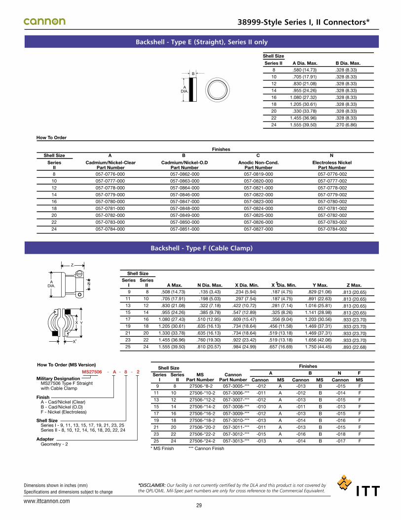
www.ittcannon.com
Dimensions shown in inches (mm) Specifications and dimensions subject to change
29
Backshell - Type E (Straight), Series II only
Backshell - Type F (Cable Clamp)
How To Order
Shell Size
Series II
Shell Size A B C N
SeriesII
Cadmium/Nickel-ClearPart Number
Cadmium/Nickel-O.DPart Number
Anodic Non-Cond.Part Number
Electroless NickelPart Number
Finishes
B
ADIA.
A Dia. Max. B Dia. Max.8
10
12
14
16
18
20
22
24
8
10
12
14
16
18
20
22
24
057-0776-000
057-0777-000
057-0778-000
057-0779-000
057-0780-000
057-0781-000
057-0782-000
057-0783-000
057-0784-000
057-0862-000
057-0863-000
057-0864-000
057-0846-000
057-0847-000
057-0848-000
057-0849-000
057-0850-000
057-0851-000
057-0819-000
057-0820-000
057-0821-000
057-0822-000
057-0823-000
057-0824-000
057-0825-000
057-0826-000
057-0827-000
057-0776-002
057-0777-002
057-0778-002
057-0779-002
057-0780-002
057-0781-002
057-0782-002
057-0783-002
057-0784-002
.580 (14.73)
.705 (17.91)
.830 (21.08)
.955 (24.26)
1.080 (27.32)
1.205 (30.61)
.330 (33.78)
1.455 (36.96)
1.555 (39.50)
.328 (8.33)
.328 (8.33)
.328 (8.33)
.328 (8.33)
.328 (8.33)
.328 (8.33)
.328 (8.33)
.328 (8.33)
.270 (6.86)
How To Order (MS Version)
MS27506Military Designation
MS27506 Type F Straight with Cable Clamp
A - Cad/Nickel (Clear) B - Cad/Nickel (O.D) F - Nickel (Electroless)
Series I - 9, 11, 13, 15, 17, 19, 21, 23, 25 Series II - 8, 10, 12, 14, 16, 18, 20, 22, 24
Geometry - 2
Finish
Shell Size
Adapter
- A 8 2- -
Shell Size Series
I Series
II
Shell Size Series
I Series
II MS
Part Number Cannon
Part Number A
Cannon Cannon Cannon MS MS MS
B N F
Finishes
A Max. N Dia. Max. X Dia. Min. Y Max. X Dia. Min. 1 A DIA. N
1 X
X Y
9
11
13
15
17
19
21
23
25
8
10
12
14
16
18
20
22
24
9
11
13
15
17
19
21
23
25
* MS Finish *** Cannon Finish
8
10
12
14
16
18
20
22
24
27506-*8-2
27506-*10-2
27506-*12-2
27506-*14-2
27506-*16-2
27506-*18-2
27506-*20-2
27506-*22-2
27506-*24-2
057-3005-***
057-3006-***
057-3007-***
057-3008-***
057-3009-***
057-3010-***
057-3011-***
057-3012-***
057-3013-***
-012
-011
-012
-010
-012
-013
-011
-015
-013
-013
-012
-013
-011
-013
-014
-013
-016
-014
-015
-014
-015
-013
-015
-016
-015
-018
-017
A
A
A
A
A
A
A
A
A
B
B
B
B
B
B
B
B
B
F
F
F
F
F
F
F
F
F
.508 (14.73)
.705 (17.91)
.830 (21.08)
.955 (24.26)
1.080 (27.43)
1.205 (30.61)
1.330 (33.78)
1.455 (36.96)
1.555 (39.50)
.135 (3.43)
.198 (5.03)
.322 (7.18)
.385 (9.78)
.510 (12.95)
.635 (16.13)
.635 (16.13)
.760 (19.30)
.810 (20.57)
.234 (5.94)
.297 (7.54)
.422 (10.72)
.547 (12.89)
.609 (15.47)
.734 (18.64)
.734 (18.64)
.922 (23.42)
.984 (24.99)
.187 (4.75)
.187 (4.75)
.281 (7.14)
.325 (8.26)
.356 (9.04)
.456 (11.58)
.519 (13.18)
.519 (13.18)
.657 (16.69)
.829 (21.06)
.891 (22.63)
1.016 (25.81)
1.141 (28.98)
1.203 (30.56)
1.469 (37.31)
1.469 (37.31)
1.656 (42.06)
1.750 (44.45)
Z.
.813 (20.65)
.813 (20.65)
.813 (20.65)
.813 (20.65)
.933 (23.70)
.933 (23.70)
.933 (23.70)
.933 (23.70)
.893 (22.68)
Z Max.
38999-Style Series I, II Connectors*
*DISCLAIMER: Our facility is not currently certified by the DLA and this product is not covered by the QPL/QML. Mil-Spec part numbers are only for cross reference to the Commercial Equivalent.

www.ittcannon.com
Dimensions shown in inches (mm) Specifications and dimensions subject to change
30
Backshell Series III
M85049/ 38 S 9 W
Military Designator
Type Straight Cable Clamp 38 90° with Cable Clamp 39
Configuration Self Locking S Nonself Locking*
*For Nonself locking, leave designator blank
Shell Size Series III 9, 11, 13, 15, 17, 19, 21, 23, 25
Finish Electroless Nickel N OD Cadmium
over electroless nickel W
38999-Style Series III Connectors*
Shell SizeSeries III
MilitaryPart Number
Nickel
MilitaryPart NumberOD Cadmium
9
11
13
15
17
19
21
23
25
M85049/38-9N
M85049/38-11N
M85049/38-13N
M85049/38-15N
M85049/38-17N
M85049/38-19N
M85049/38-21N
M85049/38-23N
M85049/38-25N
M85049/38-9W
M85049/38-11W
M85049/38-13W
M85049/38-15W
M85049/38-17W
M85049/38-19W
M85049/38-21W
M85049/38-23W
M85049/38-25W
Shell SizeSeries III
MilitaryPart Number
Nickel
MilitaryPart NumberOD Cadmium
9
11
13
15
17
19
21
23
25
M85049/38S-9N
M85049/38S-11N
M85049/38S-13N
M85049/38S-15N
M85049/38S-17N
M85049/38S-19N
M85049/38S-21N
M85049/38S-23N
M85049/38S-25N
M85049/38S-9W
M85049/38S-11W
M85049/38S-13W
M85049/38S-15W
M85049/38S-17W
M85049/38S-19W
M85049/38S-21W
M85049/38S-23W
M85049/38S-25W
Shell SizeSeries III
MilitaryPart Number
Nickel
MilitaryPart NumberOD Cadmium
9
11
13
15
17
19
21
23
25
M85049/39-9N
M85049/39-11N
M85049/39-13N
M85049/39-15N
M85049/39-17N
M85049/39-19N
M85049/39-21N
M85049/39-23N
M85049/39-25N
M85049/39-9W
M85049/39-11W
M85049/39-13W
M85049/39-15W
M85049/39-17W
M85049/39-19W
M85049/39-21W
M85049/39-23W
M85049/39-25W
Shell SizeSeries III
MilitaryPart Number
Nickel
MilitaryPart NumberOD Cadmium
9
11
13
15
17
19
21
23
25
M85049/39S-9N
M85049/39S-11N
M85049/39S-13N
M85049/39S-15N
M85049/39S-17N
M85049/39S-19N
M85049/39S-21N
M85049/39S-23N
M85049/39S-25N
M85049/39S-9W
M85049/39S-11W
M85049/39S-13W
M85049/39S-15W
M85049/39S-17W
M85049/39S-19W
M85049/39S-21W
M85049/39S-23W
M85049/39S-25W
Straight Cable Clamp - Nonself Locking Straight Cable Clamp - Self Locking
90° with Cable Clamp - Nonself Locking 90° with Cable Clamp - Self Locking
M85049/38
M85049/39
*DISCLAIMER: Our facility is not currently certified by the DLA and this product is not covered by the QPL/QML. Mil-Spec part numbers are only for cross reference to the Commercial Equivalent.*DISCLAIMER: Our facility is not currently certified by the DLA and this product is not covered by
the QPL/QML. Mil-Spec part numbers are only for cross reference to the Commercial Equivalent.*DISCLAIMER: Our facility is not currently certified by the DLA and this product is not covered by the QPL/QML. Mil-Spec part numbers are only for cross reference to the Commercial Equivalent.
*DISCLAIMER: Our facility is not currently certified by the DLA and this product is not covered bythe QPL/QML. Mil-Spec part numbers are only for cross reference to the Commercial Equivalent.

www.ittcannon.com
Dimensions shown in inches (mm) Specifications and dimensions subject to change
31
Backshell - Type P (Potting Boot)
Potting Boot Adapter Ring
Wire Sealing Plugs
How To Order (MS Version)
Shell SizeSeries II
Series IIMS27486
Part NumberCannon
Part NumberSeries IMS27486 - 10 - 1
Series I - 9, 11, 13, 15, 17, 19, 21, 23, 25Series II - 8, 10, 12, 14, 16, 18, 20 , 22 , 24
1 - Straight Cup
NOTE: When ordering the MS version you must specify both MS numbers for the Potting Boot and the Adapter Ring.
MS DesignationShell Size
Shell Size
A Dia. Max. B Dia. Max.Series I8
10
12
14
16
18
20
22
24
.598 (15.19)
.723 (18.36)
.847 (21.51)
.969 (24.61)
1.087 (27.61)
1.211 (30.76)
1.336 (33.93)
1.461 (37.11)
1.586 (40.28)
.434 (11.02)
.548 (13.92)
.673 (17.09)
.798 (20.27)
.899 (22.83)
1.024 (26.01)
1.141 (29.98)
1.274 (32.36)
1.399 (35.53)
9
11
13
15
17
19
21
23
25
A DIA.
B
8
10
12
14
16
18
20
22
24
27486-**-1
27486-**-1
27486-**-1
27486-**-1
27486-**-1
27486-**-1
27486-**-1
27486-**-1
27486-**-1
040-0185-000
040-0169-000
040-0170-000
040-0171-000
040-0172-000
040-0173-000
040-0174-000
040-0175-000
040-0176-000
9
11
13
15
17
19
21
23
25
** Only even numbered shell size is applicable.
How To Order (MS Version)
Shell SizeSeries
ISeries
IIMS27485
Part NumberCannon
Part Number Cannon Cannon CannonMS MS MS
FNickel
NElectroless
BCadmium/Nickel-O.D
ACadmium/Nickel Clear
Finishes
Series I - 9, 11, 13, 15, 17, 19, 21, 23, 25Series II - 8, 10, 12, 14, 16, 18, 20 , 22 , 24
A - Cad/Nickel (Clear)B - Cad/Nickel (O.D)F - Nickel (Electroless)
MS FinishOnly even numbered shell size is applicableCannon Finish
***
***
NOTE: When ordering the MS version you must specify both MS numbers for the Potting Boot and the Adapter Ring.
MS27485 - A - 8
Miltary DesignationFinish
Shell Size
8
10
12
14
16
18
20
22
24
27485-*-**
27485-*-**
27485-*-**
27485-*-**
27485-*-**
27485-*-**
27485-*-**
27485-*-**
27485-*-**
237-0887-***
237-0874-***
237-0875-***
237-0876-***
237-0877-***
237-0878-***
237-0879-***
237-0880-***
237-0881-***
-000
-000
-000
-000
-000
-000
-000
-000
-000
-001
-001
-001
-001
-001
-001
-001
-001
-001
-002
-002
-002
-002
-002
-002
-002
-003
-003
B
B
B
B
B
B
B
B
B
F
F
F
F
F
F
F
F
F
A
A
A
A
A
A
A
A
A
9
11
13
15
17
19
21
23
25
Series IIISize
Series I & IISize
Part NumberCannon MS27488 Color Code
Wire sealing plugs meet MS27488 standards. The plugs are color coded according to size for easy identification. Wire sealing plugs may be ordered separately.
22D
20
16
12
22D
20
16
12
225-1013-000
225-0070-000
225-0104-000
225-0105-000
MS27488-22-2
MS27488-20-2
MS27488-16-2
MS27488-12-2
Black
Red
Green
Orange
38999-Style Series I, II, III Connectors*
*DISCLAIMER: Our facility is not currently certified by the DLA and this product is not covered bythe QPL/QML. Mil-Spec part numbers are only for cross reference to the Commercial Equivalent.

www.ittcannon.com
Dimensions shown in inches (mm) Specifications and dimensions subject to change
32
38999-Style Series I, II, III Connectors*
Tools - Crimp
Tools - Plastic
Tools - Metal (MS)
ContactSize
Crimp ToolPart Number
Locator or TurretPart Number
Crimp ToolPart Number
Locator or TurretPart Number
Crimp ToolPart Number
Locator or TurretPart Number
Pin ContactSeries I/II/III
Socket ContactSeries II
Socket ContactSeries I & III
M22520/1-01 CBT-530 M22520/2-01 CBT-565
22D or 22M*
22*
20
16
12
M22520/2-01
M22520/2-01
M22520/1-01
M22520/1-01
M22520/1-01
M22520/2-01
M22520/2-01
M22520/1-01
M22520/1-01
M22520/1-01
M22520/2-09
M22520/2-09
M22520/1-04 OR TH 187
M22520/1-04 OR TH 187
M22520/1-04
M22520/2-01
M22520/2-01
M22520/1-01
M22520/1-01
M22520/1-01
M22520/2-06
M22520/2-06
M22520/1-04
M22520/1-04
M22520/1-04
M22520/2-07
M22520/2-07
M22520/1-04
M22520/1-04
M22520/1-04
Inner Conductor Crimp Tool Crimp Tool Locator
RG180 M22520/2-01 995-0002-268
RG 174, 179, 316 M22520/2-01 995-0002-268
RG 142 M22520/2-01 995-0002-268
Outer Conductor Crimp Tool Crimp Tool Locator
RG180 M22520/5-01 M22520/5-39B
RG 174, 179, 316 M22520/5-01 M22520/5-37B
RG 142 M22520/5-01 M22520/5-19B
* For reference only
8 Coax
Inner Conductor Crimp Tool Crimp Tool Locator
RG174, 179, 316 M22520/2-01 M22520/2-34
12 Coax Outer Conductor Crimp Tool Crimp Tool Locator
RG174, 179, 316 M22520/31-01 M22520/31-02
Crimp Tool Crimp Tool Locator
Center Contact M22520/2-01 K709
Intermediate Contact M22520/5-01 Y631 Die Closure B
Outer Contact M22520/5-01 Y631 Die Closure A
8 Twinax
Insertion/Extraction
ContactSize
CannonDescription
CannonPart Number
M81969Part Number
InsertionColor Tip
ExtractionColor Tip
SupersededMilitary
Part Number22D
22M*
20
16
12
8 Coax/Twinax
12 Coax
CIET-22D-01
CIET-22D-01
CIET-20-10
CIET-16-03
CIET-12-04
CET8-T
CIET-12-04
274-7048-000
274-7048-000
274-7001-000
274-7002-000
274-7003-000
323-7004-001
274-7003-000
M81969/14-01
M81969/14-01
M81969/14-10
M81969/14-03
M81969/14-04
—
M81969/14-04
MS27534-22D
MS27534-22D
MS27534-20
MS27534-16
MS27534-12
—
M527534-12
Green
Green
Red
Blue
Yellow
—
Yellow
White
White
Orange
White
White
—
White
Insertion tool not required for size 8
Insertion
Insertion
Extraction
Extraction
No.1 No.2Contact
SizeMS27495
Part NumberITT CANNONPart Number
ColorBand
MS27495Part Number
ITT CANNONPart Number
Color Band
22D OR 22M*
22*
20
16
Band No. 1 indicates tool size.Band No. 2 indicates removal tool.For reference only*
MS27495 A22M
MS27495 A22
MS27495 A20
MS27495 A16
995-0001-718
995-0001-720
995-0001-716
995-0001-732
995-0001-719
995-0001-721
995-0001-717
995-0001-731
Black
Brown
Red
Blue
White
White
White
White
MS27495 R22M
MS27495 R22
MS27495 R20
MS27495 R16
Black
Brown
Red
Blue
Insertion/Extraction
*DISCLAIMER: Our facility is not currently certified by the DLA and this product is not covered bythe QPL/QML. Mil-Spec part numbers are only for cross reference to the Commercial Equivalent.

www.ittcannon.com
Dimensions shown in inches (mm) Specifications and dimensions subject to change
Contact Insertion
Contact Extraction
3. Press tool against contact shoulder and, with
firm and even pressure, insert wired contact and
tool tip into center contact cavity. A slight click may
be heard as metal retaining tines snap into place
behind contact shoulder.
2. Using proper plastic or metal insertion tool for
corresponding contact, position wire in tip of the tool
so that the tool tip butts up against the contact
shoulder.
1. Remove hardware from plug or receptacle and
slip over wire bundle in proper order for
reassembly.
1. Remove hardware from plug or receptacle
and slide hardware back along wire bundle.
2. Using plastic or metal extraction tool with proper
color code corresponding to contact size, place wire in
tool.
3. Insert tool into contact cavity until tool tip
bottoms against the contact shoulder, expanding
clip retaining tines.
6. Reassemble plug or receptacle.5. Fill any empty wire cavities with wire sealing plugs, and4. Hold wire firmly in tool and extract wired
contact and tool. Repeat operation for all
contacts to be extracted.
5. After all contacts are inserted, fill any empty
cavities with wire sealing plugs, Ressemble plug
or receptacle hardware.
4. Remove tool and pull back lightly on wire to make
sure contact is properly seated. Repeat operation with
remainder of contacts to be inserted, beginning with
the center cavity and working outward in alternating
rows.
33
38999-Style Series I, II, III Connectors*
Wire Stripping
Wire Size A
22D or 22M*
20
16
12
* For reference only
A .125 (3.18)
.188 (4.77)
.188 (4.77)
.188 (4.77)
Strip insulation from end of wire to be crimped.(See table for proper stripping dimensions.) Do notcut or damage wire strands.
VISUAL INSPECTION HOLE
1. Insert stripped wire into contact crimp pot.Wire must be visible thru inspection hole.
3. Release crimped contact and wire from tool. Becertain the wire is visible thru inspection hole in contact.
2. Using correct crimp tool and locator, cycle the tool once to be sure the indentors are open. Insertcontact and wire into locator. Squeeze tool handles firmly and completely to insure a proper crimp. The tool will not release unless the crimp indentors in the tool head have been fully actuated.
Assembly Instructions
Contact Crimping
*DISCLAIMER: Our facility is not currently certified by the DLA and this product is not covered bythe QPL/QML. Mil-Spec part numbers are only for cross reference to the Commercial Equivalent.

www.ittcannon.com
Dimensions shown in inches (mm) Specifications and dimensions subject to change
34
38999-Style Series I, II, III Connectors*
38999-Style Specifications
After preloading to 3 pounds maximum, the force shall be applied at a rate of approximately 1 pound per second and maintained at full load for 5-10 seconds. No damage to contacts or insert shall result nor shall the contacts be dislocated from their normal position in the connector more than 0.012 inch under the given load. Failure to meet these requirements shall be cause for rejection.
The following excerpts are some of the parameter requirements of the MIL-DTL-3899 Specification.
For qualification testing, mating halves shall be coupled and uncoupled, measuring the torques necessary.The torques required to couple and uncouple mating connector halves shall fall within the limits specifications as follows:
Connector halves shall be mated and unmated 250 times for Series II with ground fingers and 500 times for Series I and III at a rate not exceeding 300 cycles per hour. The test may be performed by hand or by mechanical means, but the coupling ring shall be operated as in normal service. Failure to complete this test because of mechanical malfunction shall be cause for rejection.
An insulation resistance test shall be performed on unmated connectors in accordance with MIL-STD-202, Method 302, Test condition B. Measurement shall be made between three pairs of adjacent contacts and the shell. Failure to meet the minimum requirement of 50,000 megohms for Classes E, P, F, R, and T shall be cause for rejection.
Wired, mated connectors shall be subjected to the vibration test of MIL-STD-202, Method 214, Test Condition II, except that the duration shall be one hour in each plane. Receptacles shall be mounted on the vibration fixture by normal means. All contacts shall be wired in a series circuit and 100-500 millamperes of current shall be allowed to flow through the series circuit during vibration. Suitable means shall be employed to monitor the current flow and to indicate any discontinuity of more than 1 microsecond. The wire bundle shall be damped to the nonvibrating points at least 8 inches from the rear of the connector. Current discontinuity of 1 microsecond or more, disengagement of the mated connectors, evidence of cracking, breaking, or loosening of parts shall be cause for rejection.
Wired mated connectors shall be subjected to one shock in each direction in each of three mutually perpendicular axes. The pulse shall be approximate half sine wave of 300g ± 15% magnitude with a duration of 3 ± 1 milliseconds. Receptacles shall be mounted on a shock fixture by normal means. All contacts shall be wired in a series circuit and 100-150 ma. of current shall flow through the series circuit during shock. Suitable means shall be employed to monitor the current flow and to indicate any discontinuity of more than 1 microsecond. The wire bundle shall be clamped to fixed points at feast 8 inches from the rear of the connector, Current discontinuity of 1 microsecond or more, disengagement of the mated connectors, evidence of cracking, breaking, or loosening of parts shall be cause for rejection.
Mated connectors shall be placed in a container of water at approximately 20ºC and placed in an altitude chamber. All wire ends shall be located within the chamber and exposed to the chamber atmosphere, but not submerged. The exposed wire ends shall not be sealed. A quantity of salt, 5 percent by weight, shall be added to make the water conductive. The chamber pressure shall then be reduced to approximately one inch of mercury and maintained for thirty minutes. The chamber pressure shall then be slowly returned to atmospheric. This shall be considered one cycle. Two additional cycles shall be performed. At the end of the last cycle, while the mated connectors are still submerged, the Insulation Resistance Test (room temperature), and the High Potential Test (sea level voltages) shall be performed upon the same circuits. Failure to meet an insulation resistance minimum of 2,000 megohms or any evidence of dielectric breakdown or -flashover shall be cause for rejection.
Unmated connectors shall be immersed fully in the applicable fluid specified below for 20 hours. After removal from the fluid, each connector shall remain for one hour in free air at room temperature.a.) Jet fuel JP-4 to MIL-J-5624 b.) Aircraft lubricating oil to MIL-L-9236
Unmated connectors and individual contact samples shall be subjected to the soft spray of MIL-STD-202, Method 101, Test Condition 8 (tin plated, Class Y receptacles-24 hours). Immediately after exposure, the surfaces of the specimens shall be thoroughly washed in tap water and dried in a circulatory oven at a temperature of 38 ±3ºC (100ºF) for a period of approximately 12 hours. Any exposure of basis metal as a result of this test, shall be cause for rejection.
(Series I and 11, finish B; Series III, class W). The wired assembled plugs and receptacles shall be mated and unmated 50 cycles at a rate of 300 cycles per hour maximum. The mating and unmating shall be accomplished so that the plug and receptacle are completely separated during each cycle. The connectors shall then be subjected to the salt spray test in accordance with method 1001 of MIL-STD- 1344. The connectors shall be tested for 452 hours mated followed by 48 hours unmated. After the salt spray exposure the remaining number of durability cycles specified in 4.7.7 shall be completed.
Unmated receptacles shall be subjected to 10 cycles of thermal shock in the following manner: The receptacle shall be suspended for 10 + 1 - 0 minutes in the center of a cold water both with a volume of approximately one cubic foot. No
dimension of the bath shall be less than 10 inches. The water temperature shall not exceed 4ºC (39.20ºF) The receptacle shall be suspended for 10 1 - 0 minutes in the center of a hot water bath with a volume of approximately one cubic foot. No
dimension of the bath shall be less than 10 inches. The water temperature shall be not less than 94ºC (201ºF).The time of transfer from one bath to the other shall not exceed 5 seconds. At the end of the tenth cycle, the receptacle shall have the excess moisture shaken off and shall then be dried in a forced air oven at 66±5˚C for 15 ±1 minutes. Any evidence of damage resulting from this test shall be cause for rejection.
Contact Retention 4 5 19
TestDescription
ParagraphReference Requirements
Coupling Torque 4 5 6
Durability 4 5 7
Insulation Resistance 4 5 9
Vibration 4 5 22
Shock 4 5 23
Thermal Shock 4 5 4
Altitude Immersion 4 5 8
Solvent Immersion 4 5 29
Corrosion 4 5 12
Dynamic Salt Spray 4 5 12 2
Temperature Durability 4 5 33
Step a
Step b
Contact Size 22M* 22D 22* 20 18
Loads in Pounds ± 10% 10 10 10 15 25
TorqueShell Size Max. Min.
8/9 8 210/11 12 2
12 16 213 16 2
TorqueShell Size Max. Min.
14 20 415 20 316 24 417 24 3
TorqueShell Size Max. Min.
18 28 519 28 320 32 621 32 5
TorqueShell Size Max. Min.
22 36 723 36 524 36 725 40 5
Wired rated connectors shall be subjected to the indicated anbient temperature for a period of 1,000 hours
Series I and II (finish A) 150 (302º F) Series I and II (finish B) 175 (347º F)
Series III (class W) 175 (347º F) All other finishes 200 (392º F)
+3º
-0ºC
+3º
-0ºC
+3º
-0ºC
+3º
-0ºC
* For reference only
*DISCLAIMER: Our facility is not currently certified by the DLA and this product is not covered bythe QPL/QML. Mil-Spec part numbers are only for cross reference to the Commercial Equivalent.

www.ittcannon.com
Dimensions shown in inches (mm) Specifications and dimensions subject to change
35
Product Safety and Warranty 1. MATERIAL CONTENT AND PHYSICALFORMElectrical connectors do not usually contain hazardous materials.
Electrical connectors and individual com-ponents do not release or otherwise result in exposure to hazardous chemicals under normal conditions of use and fall under the definition of “Article,” under the Hazard Communication Standard, 29 CFR 1910.1200, and are not considered hazard-ous materials.
Solder and fluxes can be hazardous if inhaled or absorbed through the skin and should only be used as recommended by the manu-facturer. Please consult your solder and flux manufacturer for more specific application recommendations.
2. FIRE CHARACTERISTICS AND ELECTRICSHOCK HAZARDThere is no fire hazard when the connector is correctly wired and used within the specified parameters. Incorrect wiring or assembly of the connector or careless use of metal tools or conductive fluids, or transit damage to any of the component parts may cause elec-tric shock or burns. Live circuits must not be broken by separating mated connectors as this may cause arcing, ionization and burn-ing. Heat dissipation is greater at maximum resistance in a circuit. Hot spots may occur when resistance is raised locally by damage, e.g. cracked or deformed contacts, broken strands of wire. Local overheating may also result from the use of the incorrect appli-cation tools or from poor quality soldering or slack screw terminals. Overheating may occur if the ratings in the product Data Sheet/Catalog are exceeded and can cause breakdown of insulation and hence electric shock. If heating is allowed to continue it intensifies by further increasing the local resistance through loss of temper of spring contacts, formation of oxide film on contacts and wires and leakage currents through car-bonization of insulation and tracking paths. Fire can then result in the presence of com-bustible materials and this may release nox-ious fumes. Overheating may not be visually apparent. Burns may result from touching overheated components.3. HANDLINGCare must be taken to avoid damage to any component parts of electrical connec-tors during installation and use. Although there are normally no sharp edges, care must be taken when handling certain com-ponents to avoid injury to fingers. Always wear safety glasses to avoid potential injury to eyes during cleaning, soldering, fiber preparation, etc.
Electrical connectors may be damaged in transit to the customers, and damage may result in creation of hazards. Products should therefore be examined prior to instal-lation/use and rejected if found to be dam-aged. Proper lifting techniques shall be used for handling shipping cartons.
4. DISPOSALPlease recycle, reclaim or dispose of connec-tors and individual components in accor-dance with local, state and federal laws. Incineration of certain materials may release noxious or even toxic fumes..
5. APPLICATIONConnectors with exposed contacts should not be selected for use on the current sup-ply side of an electrical circuit, because an electric shock could result from touching exposed contacts on an unmated connector. Voltages in excess of 30 V ac or 42.5 V dc are potentially hazardous and care should be taken to ensure that such voltages cannot be transmitted in any way to exposed metal parts of the connector body. The connector and wiring should be checked, before mak-ing live, to have no damage to metal parts or insulators, no solder blobs, loose strands, conducting lubricants, swarf, or any other undesired conducting particles. Circuit resis-tance and continuity check should be made to make certain that there are no high resis-tance joints or spurious conducting paths. Always use the specified application tools, cleaning materials and assembly instructions documented in the Data Sheet/Catalog. Do not permit untrained personnel to wire, assemble or tamper with connectors. For operation voltage please see appropriate national regulations.
IMPORTANT GENERAL INFORMATION(i) Air and creepage paths/Operating voltage. The admissible operating voltages depend on the individual applications and the valid national and other applicable safe-ty regulations.For this reason the air and creepage path data are only reference values. Observe reduction of air and creepage paths due to PC board and/or harnessing.
(ii) TemperatureAll information given are temperature limits. The operation temperature depends on the individual application.
(iii) PressureAll pressure information given are differen-tial pressure limits. The specific differential pressure limits, across the connector inter-face, are documented in the Data Safety/catalog
(iv) Other important informationCannon continuously endeavors to improve their products. Therefore, Cannon products may deviate from the description, technical data and shape as shown in this catalog and data sheets.
Commodities in this catalog may be con-trolled for export or re-export under the Export Administration Regulations (EAR), Nuclear Regulatory Commission (NRC) Regulations, or by the International Traffic in Arms Regulations (ITAR) when specifically designed, modified or configured for mili-tary use.
ITT Cannon manufactures high quality products. However, these products are intended to be used in accordance with the specifications in this publication. Any use or application that deviates from the stated operating specifications is not recommend-ed and may be unsafe. No information and data contained in this publication shall be construed to create any liability on the part of ITT.

www.ittcannon.com
Dimensions shown in inches (mm) Specifications and dimensions subject to change
ITT Cannon ITT is a focused multi-industrial company that designs and man-ufactures highly engineered critical components and customized technology solutions. Our customers in the energy, transpor-tation and industrial markets depend on us to solve their most critical problems, and we focus on partnering with them to find solutions to their unique challenges. Founded in 1920, ITT is headquartered in White Plains, N.Y., with employees in more than 35 countries.
Our connector portfolio remains the most extensive in the industry, offering a reliable and cost effective range of inter-connect solutions with the brands of Cannon, VEAM and BIW Connector Systems. Continuous investment in technology and research & development have enabled ITT to provide new, inno-vative products and solutions to markets including:
• Automotive• Computer & Consumer Electronics• Industrial/Instrumentation• Military & Aerospace• Oil & Gas• Telecommunications/Wireless Handheld Devices• Transportation
When you specify a Cannon, VEAM or BIW Connector Systems connector, you can rely on products that are designed, devel-oped, and manufactured to the highest quality and reliability standards. This tradition of excellence is based on ITT’s corpo-rate culture of operating its businesses under the principles of Six Sigma. At ITT, Six Sigma is not just a quality philosophy but a complete corporate culture that drives the entire busi-ness. Our Value Based Management and Value Based Product Development systems are two cornerstones that allow for the development of both leadership and product engineering prin-ciples, ensuring our industry leading products are developed to the accepted market driven lead times. These principles have allowed ITT to become the market leader in all of our business portfolios.
Six Sigma ManufacturingITT Cannon operates manufacturing facilities in the United States, Germany, Italy, Mexico, China and Japan, all of which have particular product area strengths allowing ITT to offer a truly global footprint to our customers. Our facilities are world class and accommodate full vertical integration utilizing the latest manufacturing technologies including: automated and robotic machining centers, Super Market manufacturing cells,
Kanban pull systems, and automated electrical, mechanical, and optical test and inspection equipment. The combination of our manufacturing strength and our advanced manufacturing facilities allows ITT to offer products at market driven prices. Our capabilities, especially in robotics, computerized precision tooling, Kaizen Project Management, Six Sigma tools, and test-ing, give ITT the most optimized global manufacturing footprint in the interconnect industry.
The Custom DifferenceAs the industry leader in harsh environment interconnect appli-cations, ITT’s world class engineering teams will work directly with our customers to design and develop cost effective solu-tions for their applications. In many cases we may modify one of our standard designs to ensure a highly reliable solution where timing is critical. Yet, in those cases where a complete custom interconnect solution is required, ITT will work with our customer’s Engineers to design an interconnect solution which will be cost effective yet highly reliable. As professional consultants, our Engineering teams will provide a thorough systems and mechanical analysis of any proposed solution. These analyses provide our customers with sophisticated elec-trical signal and mechanical characterizations to determine the best solution for their application.
RoHS Compliance Information ITT has implemented a strict parts control plan for all ITT electronics plants worldwide that allows the Cannon, VEAM, and BIW Connector Systems product portfolios to meet the requirements of the European Union Directive 2002/95/EC bet-ter known as the Reduction of Hazardous Substances (RoHS) initiative. As appropriate, specific Cannon, VEAM, and BIW Connector Systems products may be ordered with an R prefix number which insures our customers will receive RoHS com-pliant parts for their commercial electronics applications and equipment. Since most RoHS hazardous substances center around specific metal plating and lead solder coatings, ITT’s products for RoHS compliance are available in the following plating finishes: electroless nickel, stainless steel, anodize over aluminum and gold plating. It should be noted that gold plat-ing would be recommended as the replacement for tin-lead solder when ordering board mount connectors.
36

D-Subminiature Connectors
Fiber Optic Connectors and Cable Assemblies
Rack and Panel Connectors
Microminiature Connectors
Circular/Filter/Hermetic Connectors
Pioneered by Cannon during the 1930s, our Rack & Panel Connectors offer an unmatched variety of shell configurations and insert arrangements, as well as materials, plating and contact options. Today, we are recognized as an industry leader, offering an unparalleled range of off-the-shelf and custom Rack & Panel products to align with customer needs.
As a world leader in circular, filter, and hermetic connectors, ITT can leverage its design and manufacturing expertise to fit virtually any application. Our expertise includes fast positive mating for a wide range of military applications, as well as numerous sizes and contact configurations for various harsh environments.
Cannon invented D-sub connectors in 1952. Our family of D-Subs now includes combinations of signal, power and RF, as well as severe service sealed connectors. Cannon D-Subs are available with an extensive line of backshells and accessories and are one of the most economical shielded connector solutions available.
Cannon fiber optic solutions provide an excellent performance/cost value. Performance may be tailored to the end system, with our use of superior materials and bonding agents providing highly effective solutions. Our wide variety of products include fiber optic hybrid contacts, multi-channel, rack and panel and hi-rel assemblies.
Developed first by Cannon in the 1960s, Microminiature Connectors offer high performance and reliability with exceptional versatility. Available in rectangular, circular and strip-style configurations for countless applications, many of our highly engineered Microminiature connector products meet critical customer demands in multiple applications across the Aerospace & Defense industry.
RF Connectors
ITT Cannon has been providing interconnect products to the Microwave and RF industry since 1963 (formerly The Sealectro Corporation). The RF 50 & 75 Ohm product lines cover UHF band through Ku band requirements. These connectors and cable assemblies are available with a thread type, snap type, bayonet type or slide on coupling method. The frequencies range from DC to 18+ GHz.
ITT Cannon is a leading global manufacturer of connector products serving international customers in the aerospace and defense, medical, energy, transportation and industrial end markets. Whether delivering critical specs to aircraft pilots, streaming data through communications satellites or enabling ultrasound technology that gives an expectant mother the first glimpse of her unborn child, Cannon connects the world’s most important information with the people who need it. To learn more, visit www.ittcannon.com

Connect with your ITT Cannonrepresentative today or visit us atwww.ittcannon.com
Connect with the experts.
Whether communicating with our soldiers, or with our first responders saving lives, ITT Cannon connects the world’s most important information with those who need it.
CHINA—Shenzhen City
+86.755.2726.7888
JAPAN—Kanagawa
+81.462.57.2010
USA—Watertown, CT+1.860.274.9681
GERMANY—Weinstadt
+49.7151.699.0
KOREA—Seoul
+82.2.7027111
© 2017 ITT Inc ITT Cannon 38999-Style Connectors Catalog | 20170730
The “ITT Engineered Blocks“ symbol, “Engineered for life," “ITT” and “Cannon“ are registered trademarks of ITT Inc. Specification and other data are based on information available at the time of printing, and are subject to change without notice.
Our facility is not currently certified by the DLA and this product is not covered by the QPL/QML.
HONG KONG
+852.2732.2720
TAIWAN—Taipei
+886.2.25452020
ITALY—Lainate
+39.02938721
UK—Basingstoke
+44.1256.311200
USA—Irvine, CA
+1.800.854.3028
![JOHANSSON WING DRAWING INDEX LIGHTING SCHEDULE … browser/addendum_2... · special purpose power receptacle [+ 18''] double duplex receptacle [above counter] duplex receptacle [above](https://img.pdfslide.us/doc/110x75/6038ccb23acbd8464b522a89/johansson-wing-drawing-index-lighting-schedule-browseraddendum2-special-purpose.jpg)