Embed Size (px)
Citation preview
Cover for catelog.indd 1 8/12/12 10:59 AM

Full Color Reader Spreads.indd 1 8/20/12 12:47 PM

Full Color Reader Spreads.indd 2 8/20/12 12:47 PM

Full Color Reader Spreads.indd 3 8/20/12 12:47 PM

Full Color Reader Spreads.indd 4 8/20/12 12:47 PM

Full Color Reader Spreads.indd 5 8/20/12 12:47 PM

Full Color Reader Spreads.indd 6 8/20/12 12:47 PM

Full Color Reader Spreads.indd 7 8/20/12 12:47 PM

Full Color Reader Spreads.indd 8 8/20/12 12:47 PM

Full Color Reader Spreads.indd 9 8/20/12 12:47 PM

Full Color Reader Spreads.indd 10 8/20/12 12:47 PM

Full Color Reader Spreads.indd 11 8/20/12 12:47 PM
Full Color Reader Spreads.indd 12 8/20/12 12:47 PM

Full Color Reader Spreads.indd 13 8/20/12 12:47 PM

Full Color Reader Spreads.indd 14 8/20/12 12:47 PM

Full Color Reader Spreads.indd 15 8/20/12 12:47 PM

Full Color Reader Spreads.indd 16 8/20/12 12:47 PM

®
Copyright (C) 2009-2012 All Rights ReservedMAGNUM CATALOG 2012 Rev. 8-10-12
Section 1 – Introduction 1About Magnum Piering 2Quality Manufacturing 2Quality Materials 4Technical Support 5Order Processing 5Manufacturer Warrantee 6
Section 2 – Helical Piles 7Helical Pile Product Number Legend 8Helical Pile Consolidated Specifications Table 10Helical Pile Sizing Guides 11Corrosion and Life Expectancy 23Lateral Shaft Capacity 241.5" SQR Helical Piles 251.75" SQR Helical Piles 262.8˝ O.D. Helical Piles 273.0˝ O.D. Helical Piles 283.5˝ O.D. Helical Piles 324.5˝ O.D. Helical Piles 345.5˝ O.D. Helical Piles 385.72˝ O.D. Helical Piles 408.63˝ O.D. Helical Piles 46Helical Soil Nails 48
TABLE OF CONTENTS

®
Copyright (C) 2009-2012 All Rights ReservedMAGNUM CATALOG 2012 Rev. 8-10-12
Section 3 – Steel Pile Caps 49Bearing Plate Cap Product Number Legend 50Bearing Plate Application Guide 51Tie-Back Cap Product Number Legend 53Helical Pile Cap Consolidated Specifications Table 54Helical Anchor Clevis Cap Specifications Table 58Grade Beam Caps 59Bond Bar Caps 63Tie Back Caps 68Slab Lifting Cap 75Wood Beam Caps 77Wood and Steel Post Base Caps 83Plate Caps 90Gusseted Plate Caps 108Tilted Plate Caps 110Tilt-Up Brace Caps 112
Section 4 – Drive Tools & Hole Templates 115Helical Drive Tool Consolidated Specifications Table 116Bolt Hole Template Consolidated Specifications Table 119Foot Operated Hydraulic Control 121
Section 5 – Foundation Brackets 123Bracket Product Number Legend 124Bracket Consolidated Specifications Table 125Plate Brackets 129Angle Brackets 132Gusseted Angle Brackets 134Reverse Angle Brackets 135Pivot Brackets 136Lifting Brackets 137Lifting Assembly 140Tie Back Brackets 142Concentric Brackets 143

®
Copyright (C) 2009-2012 All Rights ReservedMAGNUM CATALOG 2012 Rev. 8-10-12
Section 6 – Push Piers & Jacked Piles 147Push Pier Product Number Legend 148Push Pier Consolidated Specifications Table 149Push Pier Friction Lead Specifications Table 150Corrosion and Life Expectancy 1511.75˝ Push Piers 1523.00˝ Push Piers 1534.50˝ Push Piers 1555.5˝ Jacked Piles 1597.0˝ Jacked Piles 1608.63˝ Jacked Piles 16110.75˝ Jacked Piles 1625.5˝ - 7˝ Transition 163
Section 7 – Push Pier Rams & Accessories 1653.25˝ Bore Diam. Hydraulic Ram Kits 1662.0˝ Bore Diam. Hydraulic Ram Kits 168
Section 8 – Slabjack Piering System 171Slabjack Consolidated Specifications Table 1721.31˝ Slabjack Pier 1732.0˝ Bore Diam. Slabjack Hydraulic Ram Kit 1741.75˝ Slabjack Pier 1752.0˝ Bore Diam. High Pressure Ram Kit 176
Section 9 – Micropile Brackets & Threadbar 177Micropile Bracket Consolidated Specifications Table 178Micropile Angle Bracket 179Micropile Plate Bracket 180Micropile Sleeve Bracket 181Threadbar Product Number Legend 182Threadbar Specification Table 183Threadbar Accessory Product Number Legend 184Threadbar Accessories 185

®
Copyright (C) 2009-2012 All Rights ReservedMAGNUM CATALOG 2012 Rev. 8-10-12
Section 10 – Solar Panel Foundations 187Solar Pile Part Number Legend 188Solar Pile Consolidated Specifications Table 189
Section 11 – Earth Anchor Systems 191Deadman Anchor Part Number Legend 192Deadman Plate Anchor Consolidated Specifications Table 19312˝ Deadman Plate Anchors 194
Section 12 – Helical Post Bases 195Helical Post Base Part Number Legend 196Helical Post Base Consolidated Specifications Table 197Helical Post Base Introduction 198Standard Capacity Post Base 199High Capacity Post Base 200
Section 13 – Other Foundation Products 201Other Foundation Products Consolidated Specifications Table 2023.0˝ Crawl Space Support Post 203Basement Reinforcing Beams 204Boardwalk K-Brace System 205Boardwalk H-Brace System 206
Section 14 – Piering Hardware 207Bearing Plate Product Number Legend 208Miscellaneous Hardware Consolidated Specification Table 209
Magnum Customer Credit Application 211
Helical Book Order Form 216

®
Copyright (C) 2009-2012 All Rights ReservedMAGNUM CATALOG 2012 Rev. 8-10-12, Page 1
MA
GN
UM
PIERIN
G, IN
C.INTRODUCTION
s e c t i o n 1
®
Copyright (C) 2009-2012 All Rights ReservedMAGNUM CATALOG 2012 Rev. 8-10-12, Page 2
ABOUT MAGNUM PIERING
Magnum Piering was founded in 1981 as one of the very first foundation repair systems manufacturers in the United States. The Magnum Hydraulic Push Piering System was the company’s flagship product line. Now, after 30 years of unparalleled performance and tens of thousands of successful projects, this system is recognized by contractors across the country as the most efficient and reliable foundation underpinning system on the market.
Building on this success, the Magnum product development team designed and introduced the Magnum Helical Pile product line in 2001. The initial 3 inch diameter round shaft product line has now been expanded to include 4.5 and 5.5 inch products with bearing capacities as high as 100 tons. Magnum Helical Piles are now specified by engineers for a multitude of different applications including pedestrian boardwalks, houses, solar panels, wind turbines, gas compressors, and multi-story buildings.
The Magnum success story reached a new and important threshold in 2008 with the opening of its new manufacturing plant and world headquarters located in West Chester, Ohio. This facility provides the company with the ability to produce more foundation products, larger and longer pile sections, and expand to meet the rapidly increasing demands for Magnum Helical Pile and Magnum Push Pier products for years to come.
In addition, Magnum has made significant investments in product testing and quality assurance programs designed to improve and extend the company’s commitment to supplying the very finest products in the industry. Two of the most notable programs are:
o ISO 9001:2008 Certificationo ICC-ES Evaluation Report
These important accreditations position Magnum Piering as one of the leading companies in our industry and insure continued growth and success for our customers and employees for many years to come.
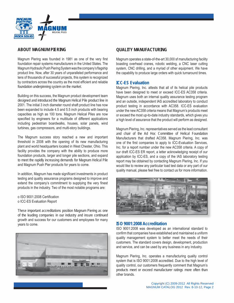
QUALITY MANUFACTURING
Magnum operates a state-of-the-art 30,000 sf manufacturing facility boasting overhead cranes, robotic welding, a CNC laser cutting system, CNC drilling, and a myriad of other equipment. We have the capability to produce large orders with quick turnaround times.
ICC-ES EvaluationMagnum Piering, Inc. attests that all of its helical pile products have been designed to meet or exceed ICC-ES AC358 criteria. Magnum uses both an internal quality assurance testing program and an outside, independent IAS accredited laboratory to conduct product testing in accordance with AC358. ICC-ES evaluation under the new AC358 criteria means that Magnum’s products meet or exceed the most up-to-date industry standards, which gives you a high level of assurance that the product will perform as designed.
Magnum Piering, Inc. representatives served as the lead consultant and chair of the Ad Hoc Committee of Helical Foundation Manufacturers that drafted AC358. Magnum Piering, Inc. was one of the first companies to apply to ICC-Evaluation Services, Inc. for a report number under the new AC358 criteria. A copy of our draft ICC-ES ER report, a letter acknowledging receipt of our application by ICC-ES, and a copy of the IAS laboratory testing report may be obtained by contacting Magnum Piering, Inc. If you would like to review any particular load test data or any part of our quality manual, please feel free to contact us for more information.
ISO 9001:2008 AccreditationISO 9001:2008 was developed as an international standard to confirm that companies have established and maintained a uniform quality management system to better meet the needs of their customers. The standard covers design, development, production and service, and can be used by any business in any industry.
Magnum Piering, Inc. operates a manufacturing quality control system that is ISO 9001:2008 accredited. Due to the high level of quality control, our customers frequently comment that Magnum’s products meet or exceed manufacturer ratings more often than other brands.

®
Copyright (C) 2009-2012 All Rights ReservedMAGNUM CATALOG 2012 Rev. 8-10-12 Page 3
ISO 9001:2008 – The Global Standard for Quality AssuranceBenefits & Assurance for Magnum Piering, Inc. Customers
• Continual improvement and striving for complete customer satisfaction
• Efficiency and productivity (minimizing defect costs and optimizing process sequences)
• Minimization of risks in product liability
• Reduced inspection and testing costs
• Reduced costs through the minimization of communication and manufacturing errors
• Consistency of service or product performance
• Increased motivation due to fewer errors and complaints
• Transparency through clearly defined processes
• Continuous process and structural improvements
• Identification and minimization of weaknesses
• The securing of a competitive edge with an internationally recognized certificate
Quality PolicyMagnum Piering, Inc. is the recognized leader in providing high quality, competitively priced foundation systems and services. We are committed to exceeding our customers’ needs through focused efforts on continuous improvement and customer service.

®
Copyright (C) 2009-2012 All Rights ReservedMAGNUM CATALOG 2012 Rev. 8-10-12, Page 4
QUALITY MATERIALS
Magnum Piering, Inc. manufactures its helical pile and steel push pier products from new, high quality steel. Mill certificates are available for shaft and plate materials.
Better Steel - Better PilesAll Magnum 3.00˝ diameter helical pile and push pier products and many of our other products are manufactured from ASTM A513 steel tubing. This premium steel tubing has higher carbon and alloy content, which means greater strength. ASTM A513 is the common designation for mechanical tubing, which is used in applications that require closer tolerances and when strength to weight ratios are important. This type of tubing is used in applications where dimensions and quality are critical for products like hydraulic cylinders and shock absorbers. Statistical process control is used to reduce variations in tube dimensions and the welding process. Other helical and resistance pile manufacturers produce products made from uncertified, used, or rejected materials.
At Magnum - Better Steel Equals Better Piles.
Patented Dual Cutting Edge HelixMagnum’s patented dual-cutting-edge (DCE) helix out performs standard circular helical bearing plates in difficult soil and bedrock conditions. The DCE helix offers a truer installation, tracks better, cuts through difficult soils such as gravel, construction debris, or trash, and will penetrate medium hard bedrock formations with an SPT blow count up to 100 to 150 blows per foot, or 50/6 to 50/4. The DCE helix gives you a better chance of getting through tough soil and bedrock situations without the need for pre-drilling. Here is what some customers are saying about Magnum’s DCE.
Mr. Joe LoudermilkPartner – Extreme Technology’s, Atlanta, GA“Magnum’s Helical Piles with the DCE Blade are the best helical piles I’ve ever installed. The blade design virtually eliminates any side-to-side (wobble) motion and the piers advance in our dense clay soils just like a screw into wood.”
Mr. Ross KirkOwner – Marco Concrete Lifting, Charleston, WV“Hands down the best blade design for penetrating our dense WestVirginia clay soils. The Magnum DCE blade even allows us to penetrate our shale formations without deflection or failure. The DCE blades are great!”
Mr. Jerry LipeOwner – Lipe Brothers Construction, Duluth, MN“Our crews specify the Magnum DCE blades for our helical piles because the blade is able to penetrate the Laurentian Shield formations in our region. Often times we encounter these layers at very shallow depths, and the DCE blades will cut through it so we can get below frost depths and into good tight clays.”
High Strength Round ShaftsMagnum offers round high-strength, structural steel tube shafts with rigid couplings because round shafts generally have greater torsional capacity, greater buckling capacity, and greater lateral capacity than square or rectangular shafts. This means that helical piles and push piers can be used in new construction for structures with lateral wind and seismic loads. It also means that you can compute buckling conventionally and you can use Magnum helical piles and push piers in soft soils without the need for grout around the shaft.
®
Copyright (C) 2009-2012 All Rights ReservedMAGNUM CATALOG 2012 Rev. 8-10-12 Page 5
TECHNICAL SUPPORTMagnum Piering, Inc. understands the importance of providing excellent technical support. Magnum strives to provide the best, most accessible, most responsive, and most knowledgeable technical support and engineering team in the industry.
ExperienceSince its founding in 1981, Magnum Piering, Inc. has gained the expertise that newer companies just don’t have. We have provided engineering support, foundation products, installation observation and load testing for a variety of diverse projects. Our projects range from residential tract homes to high-rise commercial developments, industrial gas compressors, deep excavation shoring, membrane tension structures and NASA launch pads. Our experience has resulted in an extensive and encompassing product line to meet the diverse needs of our clients.
ExpertiseOur director of engineering, Dr. Howard Perko, authored the only book currently available on helical pile installation and design, issued by a world-renowned publisher, John Wiley & Sons. Dr. Perko also authored helical pile additions to the 2009 IBC, and he was an expert consultant on writing of the NYC DOB code on helical piles. Having Magnum’s experts on your team will give you piece of mind.
Engineering ServicesMagnum Piering has partnered with Magnum Geo-Solutions, LLC to provide assistance in engineering projects involving Magnum Piering, Inc. products. Magnum Geo-Solutions, LLC currently operates an engineering office in Fort Collins, Colorado. Here a team of engineers is standing by ready and willing to help with project submittals and design-build support for foundation, shoring, underpinning, repair, and earth retention projects. Magnum Geo-Solutions, LLC’s engineers are licensed in 25 states within the U.S. and frequently provide support and advice under a peer review system throughout the World. Customers receive a separate contract and are charged by Magnum Geo-Solutions, LLC for engineering services provided.
CAD Design ServicesOur in-house CAD design department and engineers have the talent to design specialty foundation products to suit specific project requirements and the needs of our customers. Simply put in a request for quote for a specific foundation product, custom cap, or drive tool, and Magnum’s CAD department in conjunction with manufacturing and sales will turn-around a drawing and quote for your approval in typically 24 to 48 hrs.
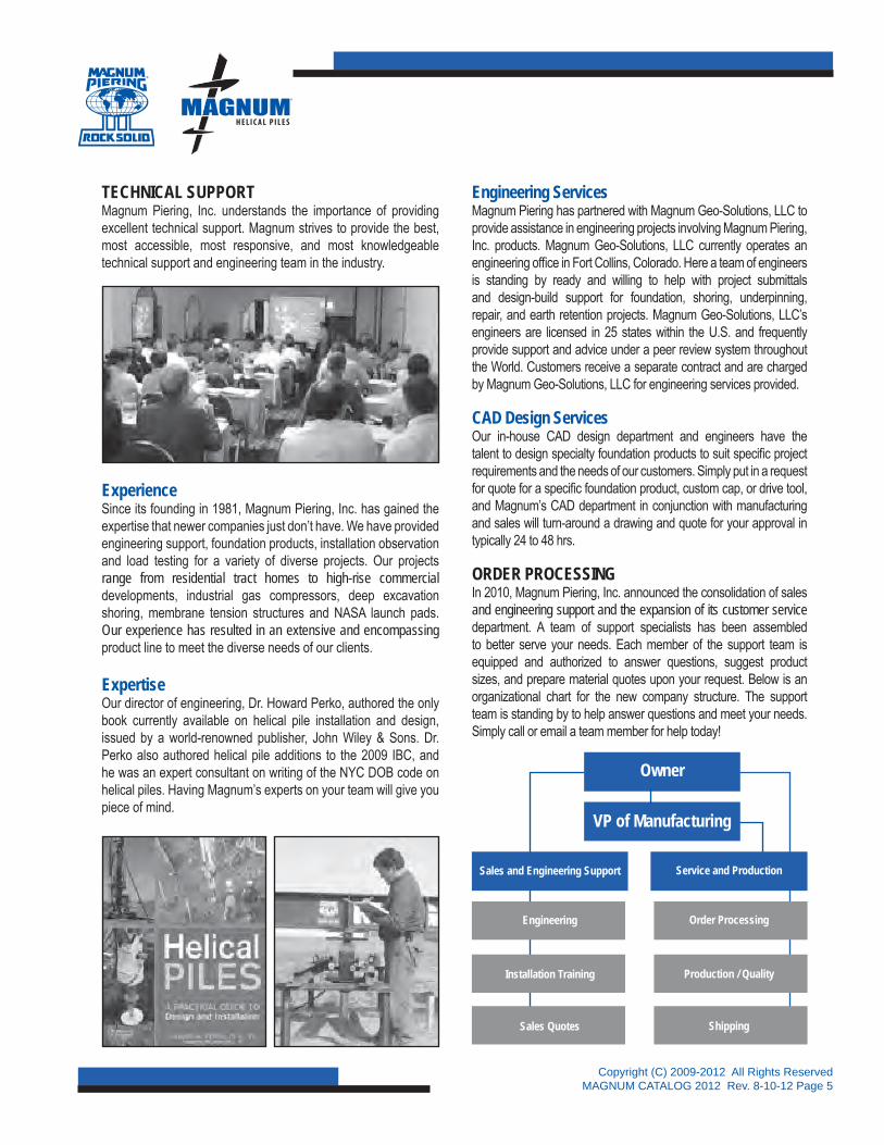
ORDER PROCESSINGIn 2010, Magnum Piering, Inc. announced the consolidation of sales and engineering support and the expansion of its customer service department. A team of support specialists has been assembled to better serve your needs. Each member of the support team is equipped and authorized to answer questions, suggest product sizes, and prepare material quotes upon your request. Below is an organizational chart for the new company structure. The support team is standing by to help answer questions and meet your needs. Simply call or email a team member for help today!
Owner
VP of Manufacturing
Sales and Engineering Support
Engineering
Installation Training
Sales Quotes
Service and Production
Order Processing
Production / Quality
Shipping
®
Copyright (C) 2009-2012 All Rights ReservedMAGNUM CATALOG 2012 Rev. 8-10-12, Page 6
Company Contact Information
MAGNUM PIERING, INC.6082 SCHUMACHER PARK DRIVE
WEST CHESTER, OH 45069800.822.PIER (7437)
WWW.MAGNUMPIERING.COM
Limitations and Conditions of Sale
A downpayment is typically required with all orders; invoice balances are due upon receipt of material shipments and are past due thirty (30) days from invoice date. A finance charge of two percent (2%) per month is assessed on all past due accounts. Delinquent accounts are subject to liens and may be sent to collections. Customers are responsible for all fees associated with collection of past due accounts. The availability of products may change with time; Magnum reserves the right to substitute different products of equal or better capacity. Quotes are typically valid for 30 days from the issue date. The law of the State of Ohio shall govern all customer and purchase agreements, their interpretation and performance.
Product sizes, if provided by Magnum Piering, Inc. or its agents and affiliates, are conceptual for bid purposed only. Customer should verify quantity, required design loads, product sizing and other project details themselves. Magnum Piering, Inc. warrants that its materials are free of defects only. Product performance is a function of installation, which Magnum cannot control, and ground conditions, which can vary with location and depth; as such, no warrantee is made, express or implied, regarding product capacity in ground. Magnum recommends bidders include provisions for additional pile length and/or obstructions in their bid documents. Magnum’s complimentary technical support is limited to standard stock drawings of Magnum products, example calculations, and assistance with preliminary pile sizing. Engineering fees will apply for stamped drawings, project specific calculations, and final designs. All engineering services are provided by Magnum Geo-Solutions, LLC.
Customers are advised to perform test installations whenever possible to verify pile depths, pressure, and torque at various locations around project sites prior to ordering material. When test piles are not possible due to schedule, cost, site access, or other reasons, customers are advised to maintain an inventory of helical pile extensions in case pile lengths are greater than anticipated from project boring logs. In order to provide the best price advantage, Magnum custom manufactures piles to specific project requirements when ordered. This allows us the ability to offer a wide variety of lengths, sizes, and configurations. Customers are encouraged to check with Magnum’s support representatives regarding specific product lead times and plan accordingly.
MANUFACTURER WARRANTEE
533201v1MAGNUM PIERING, INC.WARRANTY PROVISIONSLIMITATION ON DAMAGES
Magnum Piering, Inc. warrants its products and their parts and components to be free from defects in materials and workmanship for a period of thirty (30) years from the date of sale. Purchaser’s exclusive remedy under this warranty shall be the correction of any verified defect in workmanship and materials or the replacement of any nonconforming goods, components, or parts, and this warranty shall expire thirty (30) years after the date of sale. EXCEPT AS SPECIFICALLY SET FORTH HEREIN, MAGNUM PIERING, INC., MAKES NO OTHER WARRANTIES, EXPRESS OR IMPLIED, WITH RESPECT TO ITS PRODUCTS AND THEIR PARTS AND COMPONENTS, INCLUDING, BUT NOT LIMITED TO, ANY WARRANTIES OF MERCHANTABILITY OR FITNESS FOR A PARTICULAR PURPOSE OR USE. NOTWITHSTANDING THE FOREGOING WARRANTY, MAGNUM PIERING, INC., SHALL NOT IN ANY EVENT BE LIABLE TO PURCHASER FOR ANY INDIRECT, SPECIAL, INCIDENTAL, OR CONSEQUENTIAL DAMAGES OR LOST PROFITS ARISING OUT OF OR RELATED IN ANY WAY TO THE PURCHASE, INSTALLATION, OR USE OF THE PRODUCTS OF MAGNUM PIERING, INC., AND THE PARTS AND COMPONENTS OF THOSE PRODUCTS. THERE ARE NO WARRANTIES WHICH EXTEND BEYOND THE DESCRIPTION ON THE FACE HEREOF.
This warranty shall be interpreted and enforced in accordance with the laws of the State of Ohio without regard to the conflicts of law rules of such state, and, further, the laws of the State of Ohio shall exclusively govern any claims, demands, or controversies arising from the sale of the products of Magnum Piering, Inc.
®
Copyright (C) 2009-2012 All Rights ReservedMAGNUM CATALOG 2012 Rev. 8-10-12, Page 7
MA
GN
UM
PIERIN
G, IN
C.HELICAL PILES
s e c t i o n 2

Copyright (C) 2009-2012 All Rights ReservedMAGNUM CATALOG 2012 Rev. 8-10-12, Page 8
Mag
num
® H
elic
al P
ileP
rodu
ct N
umbe
r S
peci
ficat
ion
Lege
nd
®
Mag
num
Pie
ring,
Inc.
ISO
900
1:20
08C
ertifi
ed
Magnum Round-Shaft Helical (M
H) or
Magnum Square-Shaft Helical (M
S)
Design Wall Thickness ( 0.13˝, 0
.2˝, 0.25˝, 0
.30˝, 0.31˝, 0
.32˝,
0.36˝, 0.37˝, 0
.46˝, 0.50˝ ),
Not Used for Square Shaft
Connection Type (B)olted, (BR) Bolted Reinforced, (W
)elded, or
(WR) W
elded Reinforced
Length ( 3´, 5
´, 6´, 1
0´, 15´, 2
0´, 30´) -
Custom Sizes Available
Helix Thickness (J) - .
250˝, (K) - .
375˝, (M) - .
625˝, (O) - .
875˝
Helix Diameter (8˝, 1
0˝, 12˝, 1
4˝, 16˝, 2
0˝, 24˝ )
& Cutting Edge (Single or Dual)
Helix Diameter (8˝, 1
0˝, 12˝, 1
4˝, 16˝, 2
0˝, 24˝ )
& Cutting Edge (Single or Dual)
Helix Diameter (8˝, 1
0˝, 12˝, 1
4˝, 16˝, 2
0˝, 24˝ )
& Cutting Edge (Single or Dual)
(G) Galvanized, (NG) Non-Galvanized, or (E
P) Epoxy Powder Coated
(L)ead or (E)xtension
Shaft Diameter (2
)=2.88˝, (3)=3.0˝, (3
5)=3.5˝, (4)=4.5˝, (5
)=5.5˝,
(6)=5.72˝, (8
)=8.63˝, or Shaft D
imension (150)=1.50˝ SQR,
(175)=1.75˝ SQR
Part
No.
MH
L4
25B
10M
12S
14S
16S
G
Expl
anat
ion:
The
Mag
num
Hel
ical
Pile
pro
duct
num
ber a
bove
MH
L425
B10
M12
S14S
16SG
is fo
r a L
ead
with
4.5
˝ dia
met
er s
haft,
a .2
5˝ w
all t
hick
ness
, a B
olte
d co
nnec
tion,
10
ft. lo
ngw
ith (3
) .62
5˝ S
ingl
e Ed
ge H
elic
es 1
2,14
,16
inch
es in
dia
met
er, a
nd th
e su
rface
pre
para
tion
is G
alva
nize
d.
Not
e: S
ee “M
agnu
m P
ierin
g H
elic
al P
ile S
peci
ficat
ions
” tab
le o
n ne
xt p
age
for d
etai
led
info
rmat
ion.
Spe
cific
atio
n in
form
atio
n is
als
o av
aila
ble
at w
ww
.mag
num
pier
ing.
com
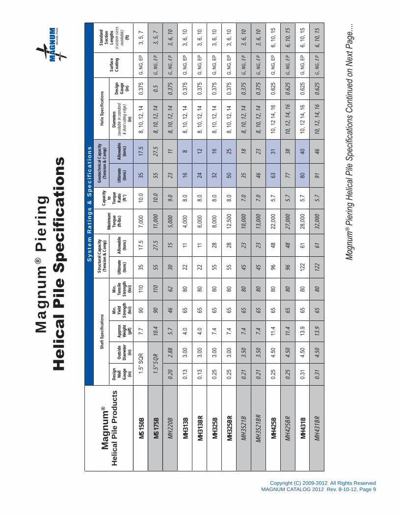
Copyright (C) 2009-2012 All Rights ReservedMAGNUM CATALOG 2012 Rev. 8-10-12, Page 9
Mag
num
®
Hel
ical
Pile
Pro
duct
s
Sy
ste
m R
ati
ng
s &
Sp
ec
ific
ati
on
s
Shaf
t Spe
cific
atio
nsSt
ruct
ural
Cap
acity
(Ten
sion
& C
omp)
Max
imum
Torq
ue(ft
-lbs)
Cap
acity
toTo
rque
Rat
io(ft
-1)
Geo
tech
nica
l Cap
acity
(Ten
sion
& C
omp)
Hel
ix S
peci
ficat
ions
Surf
ace
Coa
ting
Stan
dard
Sect
ion
Leng
ths
(cus
tom
siz
esav
aila
ble)
(ft)
Des
ign
Wal
lG
auge
(in)
Out
side
Dia
met
er(in
)
App
rox
Wei
ght
(plf)
Min
.Yi
eld
Stre
ngth
(ksi
)
Min
.Te
nsile
Stre
ngth
(ksi
)
Ulti
mat
e(to
ns)
Allo
wab
le(to
ns)
Ulti
mat
e(to
ns)
Allo
wab
le(to
ns)
Diam
eter
s(a
vaila
ble
in s
tand
ard
& du
al c
uttin
g ed
ge)
(in)
Des
ign
Gau
ge(in
)
MS1
50B
1.5”
SQ
R7.
790
110
3517
.57,
000
10.0
3517
.58,
10,
12,
14
0.37
5G
, NG
, EP
3, 5
, 7
MS1
75B
1.5”
SQ
R10
.490
110
5527
.511
,000
10.0
5527
.58,
10,
12,
14
0.5
G, N
G, E
P3,
5, 7
MH
220B
0.20
2.88
5.7
4662
3015
5,00
09.
023
118,
10,
12,
14
0.37
5G
, NG
, EP
3, 6
, 10
MH
313B
0.13
3.00
4.0
6580
2211
4,00
08.
016
88,
10,
12,
14
0.37
5G
, NG
, EP
3, 6
, 10
MH
313B
R0.
133.
004.
065
8022
116,
000
8.0
2412
8, 1
0, 1
2, 1
40.
375
G, N
G, E
P3,
6, 1
0
MH
325B
0.25
3.00
7.4
6580
5528
8,00
08.
032
168,
10,
12,
14
0.37
5G
, NG
, EP
3, 6
, 10
MH
325B
R0.
253.
007.
465
8055
2812
,500
8.0
5025
8, 1
0, 1
2, 1
40.
375
G, N
G, E
P3,
6, 1
0
MH
3521
B0.
213.
507.
465
8045
2310
,000
7.0
3518
8, 1
0, 1
2, 1
40.
375
G, N
G, E
P3,
6, 1
0
MH
3521
BR
0.21
3.50
7.4
6580
4523
13,0
007.
046
238,
10,
12,
14
0.37
5G
, NG
, EP
3, 6
, 10
MH
425B
0.25
4.50
11.4
6580
9648
22,0
005.
763
3110
, 12
14, 1
60.
625
G, N
G, E
P6,
10,
15
MH
425B
R0.
254.
5011
.465
8096
4827
,000
5.7
7738
10, 1
2, 1
4, 1
60.
625
G, N
G, E
P6,
10,
15
MH
431B
0.31
4.50
13.9
6580
122
6128
,000
5.7
8040
10, 1
2 14
, 16
0.62
5G
, NG
, EP
6, 1
0, 1
5
MH
431B
R0.
314.
5013
.965
8012
261
32,0
005.
791
4610
, 12,
14,
16
0.62
5G
, NG
, EP
6, 1
0, 1
5
Mag
num
® P
ieri
ngH
elic
al P
ile S
peci
ficat
ions
Mag
num
® P
ierin
g H
elic
al P
ile S
peci
ficat
ions
Con
tinue
d on
Nex
t Pag
e....®
Copyright (C) 2009-2012 All Rights ReservedMAGNUM CATALOG 2012 Rev. 8-10-12, Page 10
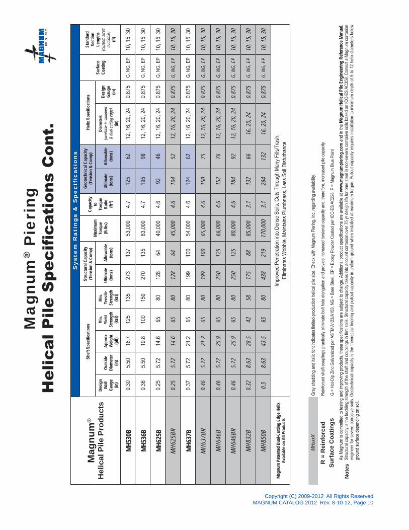
As M
agnu
m is
com
mitt
ed to
test
ing
and
impr
ovin
g pr
oduc
ts, t
hese
spe
cific
atio
ns a
re s
ubje
ct to
cha
nge.
Add
ition
al p
rodu
ct s
peci
ficat
ions
are
ava
ilabl
e at
ww
w.m
agnu
mpi
erin
g.co
m a
nd in
the
Mag
num
Hel
ical
Pile
Eng
inee
ring
Ref
eren
ce M
anua
l. St
ruct
ural
cap
acity
is th
e bu
cklin
g st
reng
th o
f the
sha
ft an
d co
uplin
gs in
firm
soi
ls. S
truct
ural
cap
acity
take
s in
to a
ccou
nt c
orro
sion
ove
r 75
yr d
esig
n lif
e fo
r bar
e st
eel i
n no
n-se
vere
cor
rosi
ve s
oils
bas
ed o
n IC
C-E
S AC
358.
Con
sult
a M
agnu
m c
orro
sion
en
gine
er fo
r sev
ere
corro
sive
soi
ls. G
eote
chni
cal c
apac
ity is
the
theo
retic
al b
earin
g an
d pu
llout
cap
acity
in u
nifo
rm g
roun
d w
hen
inst
alle
d at
max
imum
torq
ue. P
ullo
ut c
apac
ity re
quire
s in
stal
latio
n to
min
imum
dep
th o
f 5 to
12
helix
dia
met
ers
belo
w
grou
nd s
urfa
ce d
epen
ding
on
soil.
Not
es
R =
Rei
nfor
ced
Surf
ace
Coa
tings
MH
xxxX
Gra
y sh
addi
ng a
nd it
alic
font
indi
cate
s lim
ited-
prod
uctio
n he
lical
pile
siz
e. C
heck
with
Mag
num
Pie
ring,
Inc.
rega
rdin
g av
aila
bilit
y.
Rei
nfor
ced
shaf
t cou
plin
gs p
ract
ical
ly e
limin
ate
bolt
hole
elo
ngat
ion
and
prov
ide
incr
ease
d to
rsio
nal c
apac
ity a
nd, t
here
fore
, inc
reas
ed p
ile c
apac
ity.
G =
Hot
-Dip
Zin
c G
alva
nize
d pe
r AST
M A
123/
A153
, NG
= B
are
Stee
l, EP
= E
poxy
Pow
der C
oate
d pe
r IC
C-E
S AC
228,
P =
Mag
num
Blu
e Pa
int
Mag
num
® P
ieri
ngH
elic
al P
ile S
peci
ficat
ions
Con
t.
Mag
num
®
Hel
ical
Pile
Pro
duct
s
Sy
ste
m R
ati
ng
s &
Sp
ec
ific
ati
on
s
Shaf
t Spe
cific
atio
nsSt
ruct
ural
Cap
acity
(Ten
sion
& C
omp)
Max
imum
Torq
ue(ft
-lbs)
Cap
acity
toTo
rque
Rat
io(ft
-1)
Geo
tech
nica
l Cap
acity
(Ten
sion
& C
omp)
Hel
ix S
peci
ficat
ions
Surf
ace
Coa
ting
Stan
dard
Sect
ion
Leng
ths
(cus
tom
siz
esav
aila
ble)
(ft)
Des
ign
Wal
lG
auge
(in)
Out
side
Dia
met
er(in
)
App
rox
Wei
ght
(plf)
Min
.Yi
eld
Stre
ngth
(ksi
)
Min
.Te
nsile
Stre
ngth
(ksi
)
Ulti
mat
e(to
ns)
Allo
wab
le(to
ns)
Ulti
mat
e(to
ns)
Allo
wab
le(to
ns)
Diam
eter
s(a
vaila
ble
in s
tand
ard
& du
al c
uttin
g ed
ge)
(in)
Des
ign
Gau
ge(in
)
MH
530B
0.30
5.50
16.7
125
135
273
137
53,0
004.
712
562
12, 1
6, 2
0, 2
40.
875
G, N
G, E
P10
, 15,
30
MH
536B
0.36
5.50
19.8
100
150
270
135
83,0
004.
719
598
12, 1
6, 2
0, 2
40.
875
G, N
G, E
P10
, 15,
30
MH
625B
0.25
5.72
14.6
6580
128
6440
,000
4.6
9246
12, 1
6, 2
0, 2
40.
875
G, N
G, E
P10
, 15,
30
MH
625B
R0.
255.
7214
.665
8012
864
45,0
004.
610
452
12, 1
6, 2
0, 2
40.
875
G, N
G, E
P10
, 15,
30
MH
637B
0.37
5.72
21.2
6580
199
100
54,0
004.
612
462
12, 1
6, 2
0, 2
40.
875
G, N
G, E
P10
, 15,
30
MH
637B
R0.
465.
7221
.265
8019
910
065
,000
4.6
150
7512
, 16,
20,
24
0.87
5G
, NG
, EP
10, 1
5, 3
0
MH
646B
0.46
5.72
25.9
6580
250
125
66,0
004.
615
276
12, 1
6, 2
0, 2
40.
875
G, N
G, E
P10
, 15,
30
MH
646B
R0.
465.
7225
.965
8025
012
580
,000
4.6
184
9212
, 16,
20,
24
0.87
5G
, NG
, EP
10, 1
5, 3
0
MH
832B
0.32
8.63
28.5
4258
175
8885
,000
3.1
132
6616
, 20,
24
0.87
5G
, NG
, EP
10, 1
5, 3
0
MH
850B
0.5
8.63
43.5
6580
438
219
170,
000
3.1
264
132
16, 2
0, 2
40.
875
G, N
G, E
P10
, 15,
30
Mag
num
Pat
ente
d D
ual-C
uttin
g Ed
ge H
elix
Ava
ilabl
e on
All
Prod
ucts
Impr
oved
Pen
etra
tion
into
Den
se S
oils
, Cut
s Th
roug
h M
any
Fills
/Tra
sh,
Elim
inat
es W
obbl
e, M
aint
ains
Plu
mbn
ess,
Les
s S
oil D
istu
rban
ce
®

Copyright (C) 2009-2012 All Rights ReservedMAGNUM CATALOG 2012 Rev. 8-10-12, Page 11
Legend:Single Cutting Edge Dual Cutting Edge
Req
uire
d U
ltim
ate
Hel
ical
Pile
Cap
acity
(ton
s)
0
5
10
15
20
25
30
35
40
45
50
55
0 5 10 15 20 25 30 35 40 45 50
Magnum® Helical Pile Sizing Guide MS150, MS175, MH220, MH313, MH325, & MH3521 Series Helical Pilesin Cohesive Soils
Cohesive Soil Consistencyvery soft
soft mediumstiff
stiff very stiff medium hard
Standard Penetration Resistance Blow Count(blows/12 inches)
Helix Diameters =
Mechanical Limit of MH325BR Piles
Mechanical Limit of MH3521BR Piles
Mechanical Limit of MH3521B and MS150B Piles
Mechanical Limit of MH325B Pile
Mechanical Limit of MH220 and MH313BR Piles
Mechanical Limit of MH313B Pile
5-14S
5-12S
12S14S14S
10S12S14S
10D12D14D
8D10D12D
10D12D
8D10D12D
Limitations: Helical pile sizing charts represent an estimate of the theoretical ultimate capacity of helical piles in ground. Installation torque and load tests, where applicable, should be used to verify capacity. Helical pile performance is a function of installation, which Magnum cannot control, and ground conditions, which can vary with location and depth; as such, no warrantee is made, express or implied, regarding foundation product capacity in ground. Magnum recommends bidders include provisions for additional pile length and/or obstructions in their bid documents.
Mechanical Limit of MS175B Piles
®

Copyright (C) 2009-2012 All Rights ReservedMAGNUM CATALOG 2012 Rev. 8-10-12, Page 12
Legend:Single Cutting Edge Dual Cutting Edge
Req
uire
d U
ltim
ate
Hel
ical
Pile
Cap
acity
(ton
s)
0
5
10
15
20
25
30
35
40
45
50
55
0 5 10 15 20 25 30 35 40 45 50
Magnum® Helical Pile Sizing Guide MS150, MS175, MH220, MH313, MH325, & MH3521 Series Helical Pilesin Non-Cohesive Soils
Non-Cohesive Soil Density
Standard Penetration Resistance Blow Count(blows/12 inches)
Helix Diameters =
Mechanical Limit of MH325BR
Mechanical Limit of MH3521BR
Mechanical Limit of MH325B Pile
Mechanical Limit of MH220 and MH313BR Piles
Mechanical Limit of MH313B Pile
5-14S
5-12S12S14S14S
10S12S14S
10D12D14D
8D10D12D
10D12D
8D10D
12D
very loose
loose medium dense dense
Limitations: Helical pile sizing charts represent an estimate of the theoretical ultimate capacity of helical piles in ground. Installation torque and load tests, where applicable, should be used to verify capacity. Helical pile performance is a function of installation, which Magnum cannot control, and ground conditions, which can vary with location and depth; as such, no warrantee is made, express or implied, regarding foundation product capacity in ground. Magnum recommends bidders include provisions for additional pile length and/or obstructions in their bid documents.
Mechanical Limit of MS175B Piles
Mechanical Limit of MH3521B and MS150B Piles
®

Copyright (C) 2009-2012 All Rights ReservedMAGNUM CATALOG 2012 Rev. 8-10-12, Page 13
Legend:Dual Cutting Edge
Req
uire
d U
ltim
ate
Hel
ical
Pile
Cap
acity
(ton
s)
0
5
10
15
20
25
30
35
40
45
50
55
30 35 40 45 50 55 60 65 70 75 80 85 90 95 100 105
Magnum® Helical Pile Sizing Guide MS150, MS175, MH220, MH313, MH325, & MH3521 Series Helical Piles in Sedimentary Rock
Bedrock Hardness
Standard Penetration Resistance Blow Count(blows/12 inches)
Helix Diameters =
Mechanical Limit of MH325BR
Mechanical Limit of MH3521BR
Mechanical Limit of MH325B Pile
Mechanical Limit of MH220 and MH313BR Piles
Mechanical Limit of MH313B Pile
8D10D12D
10D12D
8D10D
12D
10D
Possible Refusalof Helical Pile
beyond This Point(SPT>50/6˝)
Limitations: Helical pile sizing charts represent an estimate of the theoretical ultimate capacity of helical piles in ground. Installation torque and load tests, where applicable, should be used to verify capacity. Helical pile performance is a function of installation, which Magnum cannot control, and ground conditions, which can vary with location and depth; as such, no warrantee is made, express or implied, regarding foundation product capacity in ground. Magnum recommends bidders include provisions for additional pile length and/or obstructions in their bid documents.
medium hard hard very hard
Mechanical Limit of MH3521B and MS150B Piles
Mechanical Limit of MS175B Piles
®

Copyright (C) 2009-2012 All Rights ReservedMAGNUM CATALOG 2012 Rev. 8-10-12, Page 14
Req
uire
d U
ltim
ate
Hel
ical
Pile
Cap
acity
(ton
s)
0
10
20
30
40
50
60
70
80
90
100
0 5 10 15 20 25 30 35 40 45 50
Legend:Single Cutting Edge Dual Cutting Edge
Helix Diameters =
Mechanical Limit of MH431BR Pile
5-14S
5-16S
12S14S16S
14S16S16S
12D14D16D
14D16D
12D14D
14D
Mechanical Limit of MH431B Pile
Mechanical Limit of MH425BR Pile
Mechanical Limit of MH425B Pile
Limitations: Helical pile sizing charts represent an estimate of the theoretical ultimate capacity of helical piles in ground. Installation torque and load tests, where applicable, should be used to verify capacity. Helical pile performance is a function of installation, which Magnum cannot control, and ground conditions, which can vary with location and depth; as such, no warrantee is made, express or implied, regarding foundation product capacity in ground. Magnum recommends bidders include provisions for additional pile length and/or obstructions in their bid documents.
Magnum® Helical Pile Sizing Guide MH425 & MH431 Series Helical Piles in Cohesive Soils
Standard Penetration Resistance Blow Count(blows/12 inches)
very soft
soft mediumstiff
stiff very stiff medium hard
Cohesive Soil Consistency
®

Copyright (C) 2009-2012 All Rights ReservedMAGNUM CATALOG 2012 Rev. 8-10-12, Page 15
Req
uire
d U
ltim
ate
Hel
ical
Pile
Cap
acity
(ton
s)
Standard Penetration Resistance Blow Count(blows/12 inches)
0
10
20
30
40
50
60
70
80
90
100
0 5 10 15 20 25 30 35 40 45 50
Legend:Single Cutting Edge Dual Cutting Edge
Helix Diameters =
Mechanical Limit of MH431BR Pile
5-14S5-16S
12S14S16S
14S16S16S
12D14D16D
14D16D
12D14D
14D
Mechanical Limit of MH431B Pile
Mechanical Limit of MH425BR Pile
Mechanical Limit of MH425B Pile
Non-Cohesive Soil Densityvery loose loose medium dense dense
Magnum® Helical Pile Sizing Guide MH425 & MH431 Series Helical Piles in Non-Cohesive Soils
Limitations: Helical pile sizing charts represent an estimate of the theoretical ultimate capacity of helical piles in ground. Installation torque and load tests, where applicable, should be used to verify capacity. Helical pile performance is a function of installation, which Magnum cannot control, and ground conditions, which can vary with location and depth; as such, no warrantee is made, express or implied, regarding foundation product capacity in ground. Magnum recommends bidders include provisions for additional pile length and/or obstructions in their bid documents.
®

Copyright (C) 2009-2012 All Rights ReservedMAGNUM CATALOG 2012 Rev. 8-10-12, Page 16
Req
uire
d U
ltim
ate
Hel
ical
Pile
Cap
acity
(ton
s)
Standard Penetration Resistance Blow Count(blows/12 inches)
0
10
20
30
40
50
60
70
80
90
100Legend:Dual Cutting Edge
Helix Diameters =
Mechanical Limit of MH431BR Pile
12D
14D
Mechanical Limit of MH431B Pile
16D
12D16D
14D16D
30 35 40 45 50 55 60 65 70 75 80 85 90 95 100 105
Possible Refusalof Helical Pile
beyond This Point(SPT>50/6˝)
Mechanical Limit of MH425BR Pile
Mechanical Limit of MH425B Pile
Magnum® Helical Pile Sizing Guide MH425 & MH431 Series Helical Piles in Sedimentary Rock
Bedrock Hardness
Limitations: Helical pile sizing charts represent an estimate of the theoretical ultimate capacity of helical piles in ground. Installation torque and loadtests, where applicable, should be used to verify capacity. Helical pile performance is a function of installation, which Magnum cannot control, andground conditions, which can vary with location and depth; as such, no warrantee is made, express or implied, regarding foundation product capacityin ground. Magnum recommends bidders include provisions for additional pile length and/or obstructions in their bid documents.
medium hard hard very hard
®

Copyright (C) 2009-2012 All Rights ReservedMAGNUM CATALOG 2012 Rev. 8-10-12, Page 17
Req
uire
d U
ltim
ate
Hel
ical
Pile
Cap
acity
(ton
s)
Standard Penetration Resistance Blow Count(blows/12 inches)
Helix Diameters =5-24S
5-20S
20S24S24S
16S20S24S
16D20D24D
20D24D
16D20D
20D
16S20S24S
Mechanical Limit of MH536B Pile
Mechanical Limit of MH646BR Pile
Mechanical Limit of MH646B and MH637BR Piles
Mechanical Limit of MH530B and MH637B Piles
Mechanical Limit of MH625BR Pile
Mechanical Limit of MH625B Pile
0
20
40
60
80
100
120
140
160
180
200
0 5 10 15 20 25 30 35 40 45 50
Legend:Single Cutting Edge Dual Cutting Edge
Magnum® Helical Pile Sizing Guide MH530, MH536, MH625, MH637 & MH646 Helical Piles in Cohesive Soils
Limitations: Helical pile sizing charts represent an estimate of the theoretical ultimate capacity of helical piles in ground. Installation torque and load tests, where applicable, should be used to verify capacity. Helical pile performance is a function of installation, which Magnum cannot control, and ground conditions, which can vary with location and depth; as such, no warrantee is made, express or implied, regarding foundation product capacity in ground. Magnum recommends bidders include provisions for additional pile length and/or obstructions in their bid documents.
Cohesive Soil Consistencyvery soft
soft mediumstiff
stiff very stiff medium hard
®

Copyright (C) 2009-2012 All Rights ReservedMAGNUM CATALOG 2012 Rev. 8-10-12, Page 18
Standard Penetration Resistance Blow Count(blows/12 inches)
Req
uire
d U
ltim
ate
Hel
ical
Pile
Cap
acity
(ton
s)
Helix Diameters = 5-24S
5-20S
20S24S24S
16S20S24S
16D20D24D
20D24D
16D20D
20D
Mechanical Limit of MH536B Pile
Mechanical Limit of MH646BR Pile
Mechanical Limit of MH646B and MH637BR Piles
Mechanical Limit of MH530B and MH637B Piles
Mechanical Limit of MH625BR Pile
Mechanical Limit of MH625B Pile
0
20
40
60
80
100
120
140
160
180
200
0 5 10 15 20 25 30 35 40 45 50
Legend:Single Cutting Edge Dual Cutting Edge
Magnum® Helical Pile Sizing Guide MH530, MH536, MH625, MH637 & MH646 Helical Piles in Non-Cohesive Soils
Limitations: Helical pile sizing charts represent an estimate of the theoretical ultimate capacity of helical piles in ground. Installation torque and load tests, where applicable, should be used to verify capacity. Helical pile performance is a function of installation, which Magnum cannot control, and ground conditions, which can vary with location and depth; as such, no warrantee is made, express or implied, regarding foundation product capacity in ground. Magnum recommends bidders include provisions for additional pile length and/or obstructions in their bid documents.
very loose
loose medium dense dense
Non-Cohesive Soil Density
®

Copyright (C) 2009-2012 All Rights ReservedMAGNUM CATALOG 2012 Rev. 8-10-12, Page 19
Req
uire
d U
ltim
ate
Hel
ical
Pile
Cap
acity
(ton
s)
Standard Penetration Resistance Blow Count(blows/12 inches)
30 35 40 45 50 55 60 65 70 75 80 85 90 95 100 105
Mechanical Limit of MH536B Pile
Mechanical Limit of MH646BR Pile
Mechanical Limit of MH646B and MH637BR Piles
Mechanical Limit of MH530B and MH637B Piles
Mechanical Limit of MH625BR Pile
Mechanical Limit of MH625B Pile
20
40
60
80
100
120
140
160
180
200
0
Possible Refusalof Helical Pile
beyond This Point(SPT>50/6˝)
Legend: Dual Cutting Edge
Magnum® Helical Pile Sizing Guide MH530, MH536, MH625, MH637 & MH646 Helical Piles in Sedimentary Rock
20D24D
20D
16D
24D
16D20D
Helix Diameters =
Limitations: Helical pile sizing charts represent an estimate of the theoretical ultimate capacity of helical piles in ground. Installation torque and load tests, where applicable, should be used to verify capacity. Helical pile performance is a function of installation, which Magnum cannot control, and ground conditions, which can vary with location and depth; as such, no warrantee is made, express or implied, regarding foundation product capacity in ground. Magnum recommends bidders include provisions for additional pile length and/or obstructions in their bid documents.
medium hard hard very hard
Bedrock Hardness
®
Copyright (C) 2009-2012 All Rights ReservedMAGNUM CATALOG 2012 Rev. 8-10-12, Page 20
Standard Penetration Resistance Blow Count(blows/12 inches)
Req
uire
d U
ltim
ate
Hel
ical
Pile
Cap
acity
(ton
s)
20
40
60
80
100
120
140
160
180
200
0
220
240
260
280
0 5 10 15 20 25 30 35 40 45 50
Legend:Single Cutting Edge Dual Cutting Edge
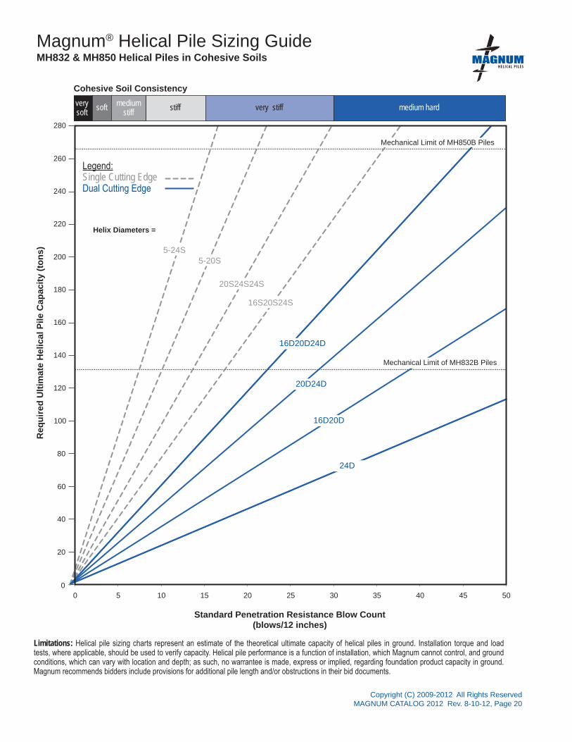
Magnum® Helical Pile Sizing Guide MH832 & MH850 Helical Piles in Cohesive Soils
Cohesive Soil Consistencyvery soft
soft mediumstiff
stiff very stiff medium hard
Limitations: Helical pile sizing charts represent an estimate of the theoretical ultimate capacity of helical piles in ground. Installation torque and load tests, where applicable, should be used to verify capacity. Helical pile performance is a function of installation, which Magnum cannot control, and ground conditions, which can vary with location and depth; as such, no warrantee is made, express or implied, regarding foundation product capacity in ground. Magnum recommends bidders include provisions for additional pile length and/or obstructions in their bid documents.
16S20S24S
16D20D24D
Mechanical Limit of MH850B Piles
Mechanical Limit of MH832B Piles
Helix Diameters =
20S24S24S
5-20S5-24S
20D24D
16D20D
24D
®

Copyright (C) 2009-2012 All Rights ReservedMAGNUM CATALOG 2012 Rev. 8-10-12, Page 21
Req
uire
d U
ltim
ate
Hel
ical
Pile
Cap
acity
(ton
s)
Standard Penetration Resistance Blow Count(blows/12 inches)
20
40
60
80
100
120
140
160
180
200
0
220
240
260
280
0 5 10 15 20 25 30 35 40 45 50
Legend:Single Cutting Edge Dual Cutting Edge
Magnum® Helical Pile Sizing Guide MH832, MH850 Helical Piles in Non-Cohesive Soils
Non-Cohesive Soil Densityvery loose
loose medium dense dense
Limitations: Helical pile sizing charts represent an estimate of the theoretical ultimate capacity of helical piles in ground. Installation torque and load tests, where applicable, should be used to verify capacity. Helical pile performance is a function of installation, which Magnum cannot control, and ground conditions, which can vary with location and depth; as such, no warrantee is made, express or implied, regarding foundation product capacity in ground. Magnum recommends bidders include provisions for additional pile length and/or obstructions in their bid documents.
Helix Diameters = Mechanical Limit of MH850B Piles
Mechanical Limit of MH832 Piles
16S20S24S
16D20D24D
20S24S24S
5-20S
5-24S
20D24D
16D20D
24D
®

Copyright (C) 2009-2012 All Rights ReservedMAGNUM CATALOG 2012 Rev. 8-10-12, Page 22
Standard Penetration Resistance Blow Count(blows/12 inches)
30 35 40 45 50 55 60 65 70 75 80 85 90 95 100 105
Req
uire
d U
ltim
ate
Hel
ical
Pile
Cap
acity
(ton
s)
20
40
60
80
100
120
140
160
180
200
0
220
240
260
280
Legend: Dual Cutting Edge
Magnum® Helical Pile Sizing Guide MH832 & MH850 Helical Piles in Sedementary Rock
Bedrock Hardness
medium hard hard very hard
Limitations: Helical pile sizing charts represent an estimate of the theoretical ultimate capacity of helical piles in ground. Installation torque and load tests, where applicable, should be used to verify capacity. Helical pile performance is a function of installation, which Magnum cannot control, and ground conditions, which can vary with location and depth; as such, no warrantee is made, express or implied, regarding foundation product capacity in ground. Magnum recommends bidders include provisions for additional pile length and/or obstructions in their bid documents.
Helix Diameters =
Possible Refusalof Helical Pile
beyond This Point(SPT>50/6˝
Mechanical Limit of MH850B Piles
Mechanical Limit of MH832B Piles
20D24D
16D20D
24D
20D
16D
®

Copyright (C) 2009-2012 All Rights ReservedMAGNUM CATALOG 2012 Rev. 8-10-12, Page 23
0 25 50 75 100 125 150
Galvanized
Epoxy Powder Coated
Bare Steel/Painted
Design Lifespan (yrs)*
Structural capacities and section properties shown in this catalog are based on a design lifespan of 75 years in most soil conditions for bare steel or painted surfaces unless noted otherwise. Design lifespan can be extended 16 years by epoxy powder coating or more than doubled by hot-dip zinc galvanizing to ASTM A123/A153.
*Design lifespan is determined by backcalculating the time required for a corrosion loss thickness of 50 mils using the rates of corrosion per ICC-ES Document AC358 Guidelines for Design of Helical Foundation Systems and Devices for moderate to highly corrosive soil conditions. Design lifespan is considerably shorter in conditions indicative of severe pile corrosion. Severe pile corrosion conditions are defined by soil resistivity less than 1,000 ohm-cm, soil pH less than 5.5, soils with high organic content, soil sulfate concentrations greater than 1,000 ppm, soils located in landfills, or soil containing mine waste. Design life also may be shortened for piles, anchors, caps and brackets exposed to atmosphere or in direct electrical contact with reinforcing steel or structural steel.
Alternative methods of corrosion loss calculation are available for varying soil conditions and with different building code authorities as shown in the table below from Perko (2009) Helical Piles: A Practical Guide to Design and Installation. Florida DOT and Canadian Building Codes provide other useful references.
MAGNUM technical support personnel can provide assistance with regard to alternative corrosion loss calculation methods. MAGNUM corrosion engineers should be consulted for severe corrosion conditions, for products exposed to atmosphere, and when product applications require direct contact with reinforcing bars or structural steel.
Magnum® Foundation Products Corrosion and Life Expectancy
®
Copyright (C) 2009-2012 All Rights ReservedMAGNUM CATALOG 2012 Rev. 8-10-12, Page 24
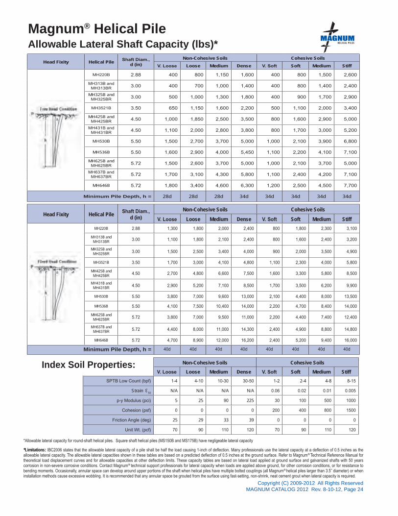
Head Fixity Helical PileShaft Diam.,
d (in)
Non-Cohesive Soils Cohesive Soils
V. Loose Loose Medium Dense V. Soft Soft Medium Stiff
MH220B 2.88 400 800 1,150 1,600 400 800 1,500 2,600
MH313B andMH313BR 3.00 400 700 1,000 1,400 400 800 1,400 2,400
MH325B and MH325BR 3.00 500 1,000 1,300 1,800 400 900 1,700 2,900
MH3521B 3.50 650 1,150 1,600 2,200 500 1,100 2,000 3,400
MH425B and MH425BR 4.50 1,000 1,850 2,500 3,500 800 1,600 2,900 5,000
MH431B andMH431BR 4.50 1,100 2,000 2,800 3,800 800 1,700 3,000 5,200
MH530B 5.50 1,500 2,700 3,700 5,000 1,000 2,100 3,900 6,800
MH536B 5.50 1,600 2,900 4,000 5,450 1,100 2,200 4,100 7,100
MH625B andMH625BR 5.72 1,500 2,600 3,700 5,000 1,000 2,100 3,700 5,000
MH637B and MH637BR 5.72 1,700 3,100 4,300 5,800 1,100 2,400 4,200 7,100
MH646B 5.72 1,800 3,400 4,600 6,300 1,200 2,500 4,500 7,700
Minimum Pile Depth, h = 28d 28d 28d 34d 34d 34d 34d 34d
Head Fixity Helical PileShaft Diam.,
d (in)
Non-Cohesive Soils Cohesive Soils
V. Loose Loose Medium Dense V. Soft Soft Medium Stiff
MH220B 2.88 1,300 1,800 2,000 2,400 800 1,800 2,300 3,100
MH313B andMH313BR 3.00 1,100 1,800 2,100 2,400 800 1,600 2,400 3,200
MH325B andMH325BR 3.00 1,500 2,500 3,400 4,000 900 2,000 3,500 4,900
MH3521B 3.50 1,700 3,000 4,100 4,800 1,100 2,300 4,000 5,800
MH425B and MH425BR 4.50 2,700 4,800 6,600 7,500 1,600 3,300 5,800 8,500
MH431B andMH431BR 4.50 2,900 5,200 7,100 8,500 1,700 3,500 6,200 9,900
MH530B 5.50 3,800 7,000 9,600 13,000 2,100 4,400 8,000 13,500
MH536B 5.50 4,100 7,500 10,400 14,000 2,200 4,700 8,400 14,000
MH625B andMH625BR 5.72 3,800 7,000 9,500 11,000 2,200 4,400 7,400 12,400
MH637B andMH637BR 5.72 4,400 8,000 11,000 14,300 2,400 4,900 8,800 14,800
MH646B 5.72 4,700 8,900 12,000 16,200 2,400 5,200 9,400 16,000
Minimum Pile Depth, h = 40d 40d 40d 40d 40d 40d 40d 40d
Non-Cohesive Soils Cohesive Soils
V. Loose Loose Medium Dense V. Soft Soft Medium Stiff
SPTB Low Count (bpf) 1-4 4-10 10-30 30-50 1-2 2-4 4-8 8-15
Strain 50
N/A N/A N/A N/A 0.06 0.02 0.01 0.005
p-y Modulus (pci) 5 25 90 225 30 100 500 1000
Cohesion (psf) 0 0 0 0 200 400 800 1500
Friction Angle (deg) 25 29 33 39 0 0 0 0
Unit Wt. (pcf) 70 90 110 120 70 90 110 120
3
Magnum® Helical Pile Allowable Lateral Shaft Capacity (lbs)*
*Limitations: IBC2006 states that the allowable lateral capacity of a pile shall be half the load causing 1-inch of deflection. Many professionals use the lateral capacity at a deflection of 0.5 inches as the allowable lateral capacity. The allowable lateral capacities shown in these tables are based on a predicted deflection of 0.5 inches at the ground surface. Refer to Magnum® Technical Reference Manual for theoretical load displacement curves and for allowable capacities at other deflection limits. These capacity tables are based on lateral load applied at ground surface and galvanized shafts with 50 years corrosion in non-severe corrosive conditions. Contact Magnum® technical support professionals for lateral capacity when loads are applied above ground, for other corrosion conditions, or for resistance to bending moments. Occasionally, annular space can develop around upper portions of the shaft when helical piles have multiple bolted couplings (all Magnum® helical piles larger than 3.5˝ diameter) or when installation methods cause excessive wobbling. It is recommended that any annular space be grouted from the surface using fast-setting, non-shrink, neat cement grout when lateral capacity is required.
*Allowable lateral capacity for round-shaft helical piles. Square shaft helical piles (MS150B and MS175B) have negligeable lateral capacity
Index Soil Properties:
®

All Magnum Products Made in U.S.A.U.S. Patents 6,058,662 and 5,234,287; Other Patents Pending.
Magnum Piering, Inc.6082 Schumacher Park Dr.
West Chester, OH 45069800-822-7437
www.magnumpiering.com
STEEL SPECIFICATIONS
PROPERTIES
STRUCTURAL CAPACITY
CAPACITY BY TORQUE
Copyright (C) 2009-2012 All Rights ReservedMAGNUM CATALOG 2012 Rev. 8-10-12, Page 25
®
GEOTECHNICAL CAPACITY BY TORQUE
MAGNUM® MS150B Helical Piles35 Ton Ultimate - 17.5 Ton Allowable CapacityHigh Strength 1.5˝ X 1.5˝, Round-Corner Square Shaft withForged upset Coupler & (1) 7/8˝ Bolt
Drawing above shows an example pile lead and extension section. Section lengths and number of helices vary with project requirements and soil conditions.
Magnum MS150B Helical Piles have 35 tons ultimate capacity and 17.5 tons working capacity in tension and compression (fully-braced conditions only). Square shaft helical piles are ideally suited for anchoring/tension applications. Lead sections and extensions couple together to extend helical bearing plates to the desired bearing stratum. Structural capacity calculations are based on average life expectancy of over 75 years for most soil conditions. Patented Magnum Dual-Cutting Edge helical bearing plates (DCE) enhance penetration through dense soils with occasional cobbles and debris. Custom lengths and helix configurations are available upon request. See Magnum Technical Reference Manual for additional information including design tools, prescriptive specifications and example plans.
Description
1.5˝ Square-Shaft Product Line Helical BearingPlate Specifications & Available Configurations
0.375˝ Thick; ASTM A36, Grade 50 ksi or Higher3.00˝ Blade Pitch8˝, 10˝, 12˝, & 14˝ DiameterStandard Circular Helix, orPatented Dual Cutting Edge HelixSharpened Edges - All Helix*3 ft. Lead or Extension - up to 2 helical bearing plates*5 ft. Lead or Extension - up to 2 helical bearing plates*7 ft. Lead or Extension - up to 3 helical bearing plates* Standard Stocking Length
SHAFT
I
Ag
S
COUPLING
BOLTS
BLADES
COATINGOPTIONS
10 ft-1
7,000 ft-lbs
35 Tons
17.5 Tons
35 Tons
17.5 Tons
New= 0.42 in4, Corroded= 0.37 in4
New= 2.25 in2, Corroded= 2.10 in2
New= 0.56 in3, Corroded= 0.51 in3
0.35˝ Min. Wall Forged Upset Collar(1) 7/8˝ Diameter SAE J429 Grade 8Zinc Coated to ASTM B695/F1941
Galvanized (G), Bare Steel (NG),Epoxy Powder Coated (EP)
Ultimate Capacity-to-Torque Ratio
Maximum Installation Torque
Ultimate Capacity
Allowable Capacity
Ultimate Compression & Tension
Allowable Compression & Tension
0.375˝ Thick, Helix Die-PressedASTM A36 Grade 50 ksi or Better
RCSS 1.5˝ x 1.5˝ASTM A29 Grade 90 KSI, or Equivalent
*Structural capacity of square-shaft helical piles equals gross area times steel strength. For compression applications, pile shafts must be fully-braced to prevent buckling in order to achieve this capacity.
Note: Helical piles shall be installed to appropriate depth into suitable bearing stratum as determined by geotechnical engineer or local practice. Capacity by torque is based on advancing pile to maximum installation torque. Deflections of 0.5˝ are common at allowable capacity. A higher factor of safety may be required for smaller deflections. For tension capacity, helical bearing plates must be deeply embedded. Load tests are recommended when practical.

®
All Magnum Products Made in U.S.A.U.S. Patents 6,058,662 and 5,234,287; Other Patents Pending.
Magnum Piering, Inc.6082 Schumacher Park Dr.
West Chester, OH 45069800-822-7437
www.magnumpiering.com
Copyright (C) 2009-2012 All Rights ReservedMAGNUM CATALOG 2012 Rev. 8-10-12, Page 26
STEEL SPECIFICATIONS
PROPERTIES
STRUCTURAL CAPACITY
CAPACITY BY TORQUEGEOTECHNICAL CAPACITY BY TORQUE
MAGNUM® MS175B Helical Piles55 Ton Ultimate - 27.5 Ton Allowable CapacityHigh Strength 1.75˝ X 1.75˝, Round-Corner Square Shaft withForged upset Coupler & (1) 1˝ Bolt
Drawing above shows an example pile lead and extension section. Section lengths and number of helices vary with project requirements and soil conditions.
Magnum MS175B Helical Piles have 55 tons ultimate capacity and 27.5 tons working capacity in compression (fully braced conditions only) and in tension. Square shaft helical piles are ideally suited for anchoring/tension applications. Lead sections and extensions couple together to extend helical bearing plates to the desired bearing stratum. Structural capacity calculations are based on average life expectancy of over 75 years for most soil conditions. Patented Magnum Dual-Cutting Edge helical bearing plates (DCE) enhance penetration through dense soils with occasional cobbles and debris. Custom lengths and helix configurations are available upon request. See Magnum Technical Reference Manual for additional information including design tools, prescriptive specifications and example plans.
Description
1.75˝ Square-Shaft Product Line Helical BearingPlate Specifications & Available Configurations
0.375˝ Thick; ASTM A36, Grade 50 ksi or Higher3.00˝ Blade Pitch8˝, 10˝, 12˝, & 14˝ DiameterStandard Circular Helix, orPatented Dual Cutting Edge HelixSharpened Edges - All Helix*3 ft. Lead or Extension - up to 2 helical bearing plates*5 ft. Lead or Extension - up to 2 helical bearing plates*7 ft. Lead or Extension - up to 3 helical bearing plates* Standard Stocking Length
SHAFT
I
Ag
S
COUPLING
BOLTS
BLADES
COATINGOPTIONS
10 ft-1
11,000 ft-lbs
55 Tons
27.5 Tons
55 Tons
27.5 Tons
New= 0.78 in4, Corroded= 0.70 in4
New= 3.06 in2, Corroded= 2.89 in2
New= 0.89 in3, Corroded= 0.82 in3
0.25˝ Min. Wall Forged Upset Collar(1) 1˝ Diameter SAE J429 Grade 8Zinc Coated to ASTM B695/F1941
Galvanized (G), Bare Steel (NG),Epoxy Powder Coated (EP)
Ultimate Capacity-to-Torque Ratio
Maximum Installation Torque
Ultimate Capacity
Allowable Capacity
Ultimate Compression & Tension
Allowable Compression & Tension
0.5˝ Thick, Helix Die-PressedASTM A36 Grade 50 ksi or Better
RCSS 1.75˝ x 1.75˝ASTM A29 Grade 90 KSI, or Equivalent
*Structural capacity of square-shaft helical piles equals gross area times steel strength. For compression applications, pile shafts must be fully-braced to prevent buckling in order to achieve this capacity.
Note: Helical piles shall be installed to appropriate depth into suitable bearing stratum as determined by geotechnical engineer or local practice. Capacity by torque is based on advancing pile to maximum installation torque. Deflections of 0.5˝ are common at allowable capacity. A higher factor of safety may be required for smaller deflections. For tension capacity, helical bearing plates must be deeply embedded. Load tests are recommended when practical.

All Magnum Products Made in U.S.A.U.S. Patents 6,058,662 and 5,234,287; Other Patents Pending.
Magnum Piering, Inc.6082 Schumacher Park Dr.
West Chester, OH 45069800-822-7437
www.magnumpiering.com
STEEL SPECIFICATIONS
PROPERTIES
STRUCTURAL CAPACITY
CAPACITY BY TORQUE
Copyright (C) 2009-2012 All Rights ReservedMAGNUM CATALOG 2012 Rev. 8-10-12, Page 27
®
2 7/8˝ Product Line Helical Bearing PlateSpecifications & Available Configurations
0.375˝ Thick; ASTM A36 or Higher3.00˝ Helix Pitch8˝, 10˝, 12˝, 14˝ DiameterStandard Circular Helix, orPatented Dual Cutting Edge HelixSharpened Edges - All Helix*3 ft. Lead or Extension - up to 2 helical bearing plates*6 ft. Lead or Extension - up to 3 helical bearing plates*10 ft. Lead or Extension - up to 6 helical bearing plates*15 ft. Lead or Extension - up to 10 helical bearing plates* Standard Stocking Length
MAGNUM® MH220B Helical Piles23 Ton Ultimate - 11 Ton Allowable CapacityStandard 2.875˝ Diameter, 0.20˝ Wall, Round-Shaft withRigid Coupler & (1) 7/8˝ Bolt
Magnum MH220B Helical Piles have 23 tons ultimate capacity and 11 tons working capacity in compression and tension. Lead sections and extensions couple together to extend helical bearing plates to the desired bearing stratum. Round shafts offer increased lateral and buckling resistance compared to solid square shafts. Capacity calculations are based on average life expectancy of over 75 years for most soil conditions. Patented Magnum Dual-Cutting Edge helical bearing plates (DCE) enhance penetration through dense soils with occasional cobbles and debris. Custom lengths and helix configurations are available upon request. See Magnum Technical Reference Manual for additional information including design tools, prescriptive specifications and example plans.
SHAFT
I
Ag
S
COUPLING
BOLTS
BLADES
COATINGOPTIONS
9 ft-1
5,000 ft-lbs
30 Tons
15 Tons
23 Tons
11 Tons
New= 1.51 in4, Corroded= 1.13 in4
New= 1.68 in2, Corroded= 1.26 in2
New= 1.05 in3, Corroded= 0.80 in3
Outer 1/4˝ Sleeve(1) 7/8˝ Diam. SAE J429 Grade 5Zinc Coated to ASTM B695/F1941
Galvanized (G), Bare Steel (NG),Epoxy Powder Coated (EP)
Ultimate Capacity-to-Torque Ratio
Maximum Installation Torque
Ultimate Capacity
Allowable Capacity
Ultimate Compression & Tension
Allowable Compression & Tension
3/8˝ Thick, Helix Die-PressedASTM A36, or Better
2.5” Nominal Sched. 40 PipeASTM A500 Grade C, or Equivalent
Note: Helical piles shall be installed to appropriate depth into suitable bearing stratum as determined by geotechnical engineer or local practice. Capacity by torque is based on advancing pile to maximum installation torque. A minimum factor of safety of 2.0 is recommended for determining allowable capacity from correlations with final installation torque. Deflections of 0.5˝ are typical at allowable capacity. A higher factor of safety may be required for smaller deflections. For tension capacity, helical bearing plates must be deeply embedded. Load tests are recommended when practical.
Description
Drawing above shows an example pile lead and extension section. Section lengths and number of helices vary with project requirements and soil conditions.

®
All Magnum Products Made in U.S.A.U.S. Patents 6,058,662 and 5,234,287; Other Patents Pending.
Magnum Piering, Inc.6082 Schumacher Park Dr.
West Chester, OH 45069800-822-7437
www.magnumpiering.com
Copyright (C) 2009-2012 All Rights ReservedMAGNUM CATALOG 2012 Rev. 8-10-12, Page 28
STEEL SPECIFICATIONS
PROPERTIES
STRUCTURAL CAPACITY
CAPACITY BY TORQUE
3.0˝ Product Line Helical Bearing PlateSpecifications & Available Configurations
0.375˝ Thick; ASTM A36 or Higher3.00˝ Helix Pitch8˝, 10˝, 12˝, 14˝ DiameterStandard Circular Helix, orPatented Dual Cutting Edge HelixSharpened Edges - All Helix*3 ft. Lead or Extension - up to 2 helical bearing plates*6 ft. Lead or Extension - up to 3 helical bearing plates*10 ft. Lead or Extension - up to 6 helical bearing plates*15 ft. Lead or Extension - up to 10 helical bearing plates* Standard Stocking Length
MAGNUM® MH313B Helical Piles16 Ton Ultimate - 8 Ton Allowable CapacityHigh-Strength 3.00˝ Diameter, 0.125˝ Wall, Round-Shaft withRigid Coupler & (1) 7/8˝ Bolt
Magnum MH313B Helical Piles have 16 tons ultimate capacity and 8 tons working capacity in compression and tension. Lead sections and extensions couple together to extend helical bearing plates to the desired bearing stratum. Round shafts offer increased lateral and buckling resistance compared to solid square shafts. Capacity calculations are based on average life expectancy of over 75 years for most soil conditions. Patented Magnum Dual-Cutting Edge helical bearing plates (DCE) enhance penetration through dense soils with occasional cobbles and debris. Custom lengths and helix configurations are available upon request. See Magnum Technical Reference Manual for additional information including design tools, prescriptive specifications and example plans.
SHAFT
I
AgS
COUPLING
BOLTS
BLADES
COATINGOPTIONS
8 ft-1
4,000 ft-lbs
22 Tons
11 Tons
16 Tons
8 Tons
New= 1.17 in4, Corroded= 0.70 in4
New= 1.13 in2, Corroded= 0.68 in2
New= 0.78 in3, Corroded= 0.48 in3
Outer 0.25˝ Sleeve(1) 7/8˝ Diam. SAE J429 Grade 5Zinc Coated to ASTM B695/F1941
Galvanized (G), Bare Steel (NG),Epoxy Powder Coated (EP)
Ultimate Capacity-to-Torque Ratio
Maximum Installation Torque
Ultimate Capacity
Allowable Capacity
Ultimate Compression & Tension
Allowable Compression & Tension
0.375˝ Thick, Helix Die-PressedASTM A36, or Better
HSS 3.00˝ x 0.125˝ WallASTM A513 65 KSI, or Equivalent
Note: Helical piles shall be installed to appropriate depth into suitable bearing stratum as determined by geotechnical engineer or local practice. Capacity by torque is based on advancing pile to maximum installation torque. A minimum factor of safety of 2.0 is recommended for determining allowable capacity from correlations with final installation torque. Deflections of 0.5˝ are typical at allowable capacity. A higher factor of safety may be required for smaller deflections. For tension capacity, helical bearing plates must be deeply embedded. Load tests are recommended when practical.
Description
Drawing above shows an example pile lead and extension section. Section lengths and number of helices vary with project requirements and soil conditions.

All Magnum Products Made in U.S.A.U.S. Patents 6,058,662 and 5,234,287; Other Patents Pending.
Magnum Piering, Inc.6082 Schumacher Park Dr.
West Chester, OH 45069800-822-7437
www.magnumpiering.com
STEEL SPECIFICATIONS
PROPERTIES
STRUCTURAL CAPACITY
CAPACITY BY TORQUE
Copyright (C) 2009-2012 All Rights ReservedMAGNUM CATALOG 2012 Rev. 8-10-12, Page 29
®
3.0˝ Product Line Helical Bearing PlateSpecifications & Available Configurations
0.375˝ Thick; ASTM A36 or Higher3.00˝ Helix Pitch8˝, 10˝, 12˝, 14˝ DiameterStandard Circular Helix, orPatented Dual Cutting Edge HelixSharpened Edges - All Helix*3 ft. Lead or Extension - up to 2 helical bearing plates*6 ft. Lead or Extension - up to 3 helical bearing plates*10 ft. Lead or Extension - up to 6 helical bearing plates*15 ft. Lead or Extension - up to 10 helical bearing plates* Standard Stocking Length
MAGNUM® MH313BR Helical Piles24 Ton Ultimate - 12 Ton Allowable CapacityHigh-Strength 3.0˝ Diameter, 0.125˝ Wall, Round-Shaft withReinforced (R) Dual Sleeve Rigid Coupler & (1) 7/8˝ Bolt
Magnum MH313BR Helical Piles have 24 tons ultimate capacity and 12 tons working capacity in compression and tension. Lead sections and extensions couple together to extend helical bearing plates to the desired bearing stratum. Round shafts offer increased lateral and buckling resistance compared to solid square shafts. Capacity calculations are based on average life expectancy of over 75 years for most soil conditions. Patented Magnum Dual-Cutting Edge helical bearing plates (DCE) enhance penetration through dense soils with occasional cobbles and debris. Custom lengths and helix configurations are available upon request. See Magnum Technical Reference Manual for additional information including design tools, prescriptive specifications and example plans.
SHAFT
I
Ag
S
COUPLING
BOLTS
BLADES
COATINGOPTIONS
8 ft-1
6,000 ft-lbs
22 Tons
11 Tons
24 Tons
12 Tons
New= 1.17 in4, Corroded= 0.70 in4
New= 1.13 in2, Corroded= 0.68 in2
New= 0.78 in3, Corroded= 0.48 in3
Outer 0.25˝ Sleeve with 0.125˝ Insert(1) 7/8˝ Diam. SAE J429 Grade 5Zinc Coated to ASTM B695/F1941
Galvanized (G), Bare Steel (NG),Epoxy Powder Coated (EP)
Ultimate Capacity-to-Torque Ratio
Maximum Installation Torque
Ultimate Capacity
Allowable Capacity
Ultimate Compression & Tension
Allowable Compression & Tension
0.375˝ Thick, Helix Die-PressedASTM A36, or Better
HSS 3.00˝ x 0.125˝ WallASTM A513 65 KSI, or Equivalent
Note: Helical piles shall be installed to appropriate depth into suitable bearing stratum as determined by geotechnical engineer or local practice. Capacity by torque is based on advancing pile to maximum installation torque. A minimum factor of safety of 2.0 is recommended for determining allowable capacity from correlations with final installation torque. Deflections of 0.5˝ are typical at allowable capacity. A higher factor of safety may be required for smaller deflections. For tension capacity, helical bearing plates must be deeply embedded. Load tests are recommended when practical.
Description
Drawing above shows an example pile lead and extension section. Section lengths and number of helices vary with project requirements and soil conditions.

®
All Magnum Products Made in U.S.A.U.S. Patents 6,058,662 and 5,234,287; Other Patents Pending.
Magnum Piering, Inc.6082 Schumacher Park Dr.
West Chester, OH 45069800-822-7437
www.magnumpiering.com
Copyright (C) 2009-2012 All Rights ReservedMAGNUM CATALOG 2012 Rev. 8-10-12, Page 30
STEEL SPECIFICATIONS
PROPERTIES
STRUCTURAL CAPACITY
CAPACITY BY TORQUE
3.0˝ Product Line Helical Bearing PlateSpecifications & Available Configurations
0.375˝ Thick; ASTM A36 or Higher3.00˝ Helix Pitch8˝, 10˝, 12˝, 14˝ DiameterStandard Circular Helix, orPatented Dual Cutting Edge HelixSharpened Edges - All Helix*3 ft. Lead or Extension - up to 2 helical bearing plates*6 ft. Lead or Extension - up to 3 helical bearing plates*10 ft. Lead or Extension - up to 6 helical bearing plates*15 ft. Lead or Extension - up to 8 helical bearing plates* Standard Stocking Length
MAGNUM® MH325B Helical Piles32 Ton Ultimate - 16 Ton Allowable CapacityHigh-Strength 3.0˝ Diameter, 0.25˝ Wall, Round-Shaft withRigid Coupler & (1) 7/8˝ Bolt
Magnum MH325B Helical Piles have 32 tons ultimate capacity and 16 tons working capacity in compression and tension. Lead sections and extensions couple together to extend helical bearing plates to the desired bearing stratum. Round shafts offer increased lateral and buckling resistance compared to solid square shafts. Capacity calculations are based on average life expectancy of over 75 years for most soil conditions. Patented Magnum Dual-Cutting Edge helical bearing plates (DCE) enhance penetration through dense soils with occasional cobbles and debris. Custom lengths and helix configurations are available upon request. See Magnum Technical Reference Manual for additional information including design tools, prescriptive specifications and example plans.
SHAFT
I
AgS
COUPLING
BOLTS
BLADES
COATINGOPTIONS
8 ft-1
8,000 ft-lbs
40 Tons
20 Tons
32 Tons
16 Tons
New= 2.06 in4, Corroded= 1.64 in4
New= 2.16 in2, Corroded= 1.73 in2
New= 1.37 in3, Corroded= 1.11 in3
Outer 0.25˝ Sleeve(1) 7/8˝ Diam. SAE J429 Grade 5 Zinc Coated to ASTM B695/F1941
Galvanized (G), Bare Steel (NG),Epoxy Powder Coated (EP)
Ultimate Capacity-to-Torque Ratio
Maximum Installation Torque
Ultimate Capacity
Allowable Capacity
Ultimate Compression & Tension
Allowable Compression & Tension
0.375˝ Thick, Helix Die-PressedASTM A36, or Better
HSS 3.00˝ x 0.25˝ WallASTM A513 65 KSI, or Equivalent
Note: Helical piles shall be installed to appropriate depth into suitable bearing stratum as determined by geotechnical engineer or local practice. Capacity by torque is based on advancing pile to maximum installation torque. A minimum factor of safety of 2.0 is recommended for determining allowable capacity from correlations with final installation torque. Deflections of 0.5˝ are typical at allowable capacity. A higher factor of safety may be required for smaller deflections. For tension capacity, helical bearing plates must be deeply embedded. Load tests are recommended when practical.
Description
Drawing above shows an example pile lead and extension section. Section lengths and number of helices vary with project requirements and soil conditions.

All Magnum Products Made in U.S.A.U.S. Patents 6,058,662 and 5,234,287; Other Patents Pending.
Magnum Piering, Inc.6082 Schumacher Park Dr.
West Chester, OH 45069800-822-7437
www.magnumpiering.com
STEEL SPECIFICATIONS
PROPERTIES
STRUCTURAL CAPACITY
CAPACITY BY TORQUE
Copyright (C) 2009-2012 All Rights ReservedMAGNUM CATALOG 2012 Rev. 8-10-12, Page 31
®
3.0˝ Product Line Helical Bearing PlateSpecifications & Available Configurations
0.375˝ Thick; ASTM A36 or Higher3.00˝ Helix Pitch8˝, 10˝, 12˝, 14˝ DiameterStandard Circular Helix, orPatented Dual Cutting Edge HelixSharpened Edges - All Helix*3 ft. Lead or Extension - up to 2 helical bearing plates*6 ft. Lead or Extension - up to 3 helical bearing plates*10 ft. Lead or Extension - up to 6 helical bearing plates*15 ft. Lead or Extension - up to 8 helical bearing plates* Standard Stocking Length
MAGNUM® MH325BR Helical Piles50 Ton Ultimate - 25 Ton Allowable CapacityHigh-Strength 3.0˝ Diameter, 0.25˝ Wall, Round-Shaft withReinforced (R) Dual Sleeve Coupler & (1) 1˝ Bolt
Magnum MH325BR Helical Piles have 50 tons ultimate capacity and 25 tons working capacity in compression and tension. Lead sections and extensions couple together to extend helical bearing plates to the desired bearing stratum. Round shafts offer increased lateral and buckling resistance compared to solid square shafts. Capacity calculations are based on average life expectancy of over 75 years for most soil conditions. Patented Magnum Dual-Cutting Edge helical bearing plates (DCE) enhance penetration through dense soils with occasional cobbles and debris. Custom lengths and helix configurations are available upon request. See Magnum Technical Reference Manual for additional information including design tools, prescriptive specifications and example plans.
SHAFT
I
Ag
S
COUPLING
BOLTS
BLADES
COATINGOPTIONS
8 ft-1
12,500 ft-lbs
55 Tons
28 Tons
50 Tons
25 Tons
New= 2.06 in4, Corroded= 1.64 in4
New= 2.16 in2, Corroded= 1.73 in2
New= 1.37 in3, Corroded= 1.11 in3
Outer 0.31˝ Sleeve with 0.25˝ Insert(1) 1˝ Diam. SAE J429 Grade 8
Zinc Coated to ASTM B695/F1941
Galvanized (G), Bare Steel (NG),Epoxy Powder Coated (EP)
Ultimate Capacity-to-Torque Ratio
Maximum Installation Torque
Ultimate Capacity
Allowable Capacity
Ultimate Compression & Tension
Allowable Compression & Tension
0.375˝ Thick, Helix Die-PressedASTM A36, or Better
HSS 3.00˝ x 0.25˝ WallASTM A513 65 KSI, or Equivalent
Note: Helical piles shall be installed to appropriate depth into suitable bearing stratum as determined by geotechnical engineer or local practice. Capacity by torque is based on advancing pile to maximum installation torque. A minimum factor of safety of 2.0 is recommended for determining allowable capacity from correlations with final installation torque. Deflections of 0.5˝ are typical at allowable capacity. A higher factor of safety may be required for smaller deflections. For tension capacity, helical bearing plates must be deeply embedded. Load tests are recommended when practical.
Description
Drawing above shows an example pile lead and extension section. Section lengths and number of helices vary with project requirements and soil conditions.

®
All Magnum Products Made in U.S.A.U.S. Patents 6,058,662 and 5,234,287; Other Patents Pending.
Magnum Piering, Inc.6082 Schumacher Park Dr.
West Chester, OH 45069800-822-7437
www.magnumpiering.com
Copyright (C) 2009-2012 All Rights ReservedMAGNUM CATALOG 2012 Rev. 8-10-12, Page 32
STEEL SPECIFICATIONS
PROPERTIES
STRUCTURAL CAPACITY
CAPACITY BY TORQUE
3.5˝ Product Line Helical Bearing PlateSpecifications & Available Configurations
0.375˝ Thick; ASTM A36 or Higher3.00˝ Helix Pitch8˝, 10˝, 12˝, 14˝ DiameterStandard Circular Helix, orPatented Dual Cutting Edge HelixSharpened Edges - All Helix*3 ft. Lead or Extension - up to 2 helical bearing plates*6 ft. Lead or Extension - up to 3 helical bearing plates*10 ft. Lead or Extension - up to 6 helical bearing plates*15 ft. Lead or Extension - up to 8 helical bearing plates* Standard Stocking Length
MAGNUM® MH3521B Helical Piles35 Ton Ultimate - 18 Ton Allowable CapacityHigh-Strength 3.5˝ Diameter, 0.21˝ Wall, Round-Shaft withStandard Coupler & (1) 1˝ Bolt
Magnum MH3521B Helical Piles have 35 tons ultimate capacity and 18 tons working capacity in compression and tension. Lead sections and extensions couple together to extend helical bearing plates to the desired bearing stratum. Round shafts offer increased lateral and buckling resistance compared to solid square shafts. Capacity calculations are based on average life expectancy of over 75 years for most soil conditions. Patented Magnum Dual-Cutting Edge helical bearing plates (DCE) enhance penetration through dense soils with occasional cobbles and debris. Custom lengths and helix configurations are available upon request. See Magnum Technical Reference Manual for additional information including design tools, prescriptive specifications and example plans.
SHAFT
I
AgS
COUPLING
BOLTS
BLADES
COATINGOPTIONS
7 ft-1
10,000 ft-lbs
45 Tons
23 Tons
35 Tons
18 Tons
New= 2.95 in4, Corroded= 2.25 in4
New= 2.17 in2, Corroded= 1.66 in2
New= 1.68 in3, Corroded= 1.30 in3
Outer 0.31˝ Sleeve(1) 1˝ Diam. Diam. SAE J429 Grade 8
Zinc Coated to ASTM B695/F1941
Galvanized (G), Bare Steel (NG),Epoxy Powder Coated (EP)
Ultimate Capacity-to-Torque Ratio
Maximum Installation Torque
Ultimate Capacity
Allowable Capacity
Ultimate Compression & Tension
Allowable Compression & Tension
0.375˝ Thick, Helix Die-PressedASTM A36, or Better
HSS 3.50˝ x 0.21˝ WallASTM A513 65 KSI, or Equivalent
Note: Helical piles shall be installed to appropriate depth into suitable bearing stratum as determined by geotechnical engineer or local practice. Capacity by torque is based on advancing pile to maximum installation torque. A minimum factor of safety of 2.0 is recommended for determining allowable capacity from correlations with final installation torque. Deflections of 0.5˝ are typical at allowable capacity. A higher factor of safety may be required for smaller deflections. For tension capacity, helical bearing plates must be deeply embedded. Load tests are recommended when practical.
Description
Drawing above shows an example pile lead and extension section. Section lengths and number of helices vary with project requirements and soil conditions.

All Magnum Products Made in U.S.A.U.S. Patents 6,058,662 and 5,234,287; Other Patents Pending.
Magnum Piering, Inc.6082 Schumacher Park Dr.
West Chester, OH 45069800-822-7437
www.magnumpiering.com
STEEL SPECIFICATIONS
PROPERTIES
STRUCTURAL CAPACITY
CAPACITY BY TORQUE
Copyright (C) 2009-2012 All Rights ReservedMAGNUM CATALOG 2012 Rev. 8-10-12, Page 33
®
3.5˝ Product Line Helical Bearing PlateSpecifications & Available Configurations
0.375˝ Thick; ASTM A36 or Higher3.00˝ Helix Pitch8˝, 10˝, 12˝, 14˝ DiameterStandard Circular Helix, orPatented Dual Cutting Edge HelixSharpened Edges - All Helix*3 ft. Lead or Extension - up to 2 helical bearing plates*6 ft. Lead or Extension - up to 3 helical bearing plates*10 ft. Lead or Extension - up to 6 helical bearing plates*15 ft. Lead or Extension - up to 8 helical bearing plates* Standard Stocking Length
MAGNUM® MH3521BR Helical Piles46 Ton Ultimate - 23 Ton Allowable CapacityHigh-Strength 3.5˝ Diameter, 0.21˝ Wall, Round-Shaft withReinforced(R) Coupler & (1) 1˝ Bolt
Magnum MH3521BR Helical Piles have 46 tons ultimate capacity and 23 tons working capacity in compression and tension. Lead sections and extensions couple together to extend helical bearing plates to the desired bearing stratum. Round shafts offer increased lateral and buckling resistance compared to solid square shafts. Capacity calculations are based on average life expectancy of over 75 years for most soil conditions. Patented Magnum Dual-Cutting Edge helical bearing plates (DCE) enhance penetration through dense soils with occasional cobbles and debris. Custom lengths and helix configurations are available upon request. See Magnum Technical Reference Manual for additional information including design tools, prescriptive specifications and example plans.
SHAFT
I
AgS
COUPLING
BOLTS
BLADES
COATINGOPTIONS
7 ft-1
13,000 ft-lbs
45 Tons
23 Tons
46 Tons
23 Tons
New= 2.95 in4, Corroded= 2.25 in4
New= 2.17 in2, Corroded= 1.66 in2
New= 1.68 in3, Corroded= 1.30 in3
Outer 0.31˝ Sleeve with 0.25˝ Insert(1) 1˝ Diam. SAE J429 Grade 8
Zinc Coated to ASTM B695/F1941
Galvanized (G), Bare Steel (NG),Epoxy Powder Coated (EP)
Ultimate Capacity-to-Torque Ratio
Maximum Installation Torque
Ultimate Capacity
Allowable Capacity
Ultimate Compression & Tension
Allowable Compression & Tension
0.375˝ Thick, Helix Die-PressedASTM A36, or Better
HSS 3.50˝ x 0.21˝ WallASTM A513 65 KSI, or Equivalent
Note: Helical piles shall be installed to appropriate depth into suitable bearing stratum as determined by geotechnical engineer or local practice. Capacity by torque is based on advancing pile to maximum installation torque. A minimum factor of safety of 2.0 is recommended for determining allowable capacity from correlations with final installation torque. Deflections of 0.5˝ are typical at allowable capacity. A higher factor of safety may be required for smaller deflections. For tension capacity, helical bearing plates must be deeply embedded. Load tests are recommended when practical.
Description
Drawing above shows an example pile lead and extension section. Section lengths and number of helices vary with project requirements and soil conditions.

®
All Magnum Products Made in U.S.A.U.S. Patents 6,058,662 and 5,234,287; Other Patents Pending.
Magnum Piering, Inc.6082 Schumacher Park Dr.
West Chester, OH 45069800-822-7437
www.magnumpiering.com
Copyright (C) 2009-2012 All Rights ReservedMAGNUM CATALOG 2012 Rev. 8-10-12, Page 34
STEEL SPECIFICATIONS
PROPERTIES
STRUCTURAL CAPACITY
CAPACITY BY TORQUEBY TORQUE - COMPRESSION & TENSION
4.5˝ Product Line Helical Bearing PlateSpecifications & Available Configurations
0.625˝ Thick; ASTM A36 or Higher3.63˝ Helix Pitch10˝, 12˝, 14˝, 16˝ DiameterStandard Circular Helix, orPatented Dual Cutting Edge HelixSharpened Edges - All Helix*5 ft. Lead or Extension - up to 2 helical bearing plates*7 ft. Lead or Extension - up to 3 helical bearing plates*10 ft. Lead or Extension - up to 4 helical bearing plates*15 ft. Lead or Extension - up to 6 helical bearing plates* Standard Stocking Length
MAGNUM® MH425B Helical Piles63 Ton Ultimate - 31 Ton Allowable CapacityHigh-Strength 4.5˝ Diameter, 0.25˝ Wall, Round-Shaft withRigid Coupler & (2) 1-1/4˝ Bolts
Magnum MH425B Helical Piles have 63 tons ultimate capacity and 31 tons working capacity in compression and tension. Lead sections and extensions couple together to extend helical bearing plates to the desired bearing stratum. Round shafts offer increased lateral and buckling resistance compared to solid square shafts. Capacity calculations are based on average life expectancy of over 75 years for most soil conditions. Patented Magnum Dual-Cutting Edge helical bearing plates (DCE) enhance penetration through dense soils with occasional cobbles and debris. Custom lengths and helix configurations are available upon request. See Magnum Technical Reference Manual for additional information including design tools, prescriptive specifications and example plans.
SHAFT
I
AgS
COUPLING
BOLTS
BLADES
COATINGOPTIONS
5.7 ft-1
22,000 ft-lbs
96 Tons
48 Tons
63 Tons
31 Tons
New= 7.56 in4, Corroded= 6.05 in4
New= 3.34 in2, Corroded= 2.67 in2
New= 3.36 in3, Corroded= 2.72 in3
0.31˝ Wall Collar(2) 1 1/4˝ Diam. Diam. SAE J429 Grade 5
Zinc Coated to ASTM B695/F1941
Galvanized (G), Bare Steel (NG),Epoxy Powder Coated (EP)
Ultimate Capacity-to-Torque Ratio
Maximum Installation Torque
Ultimate Capacity
Allowable Capacity
Ultimate Compression & Tension
Allowable Compression & Tension
0.625˝ Thick, Helix Die-PressedASTM A36, or Better
HSS 4.50˝ x 0.25˝ WallASTM A513 65 KSI, or Equivalent
Note: Helical piles shall be installed to appropriate depth into suitable bearing stratum as determined by geotechnical engineer or local practice. Capacity by torque is based on advancing pile to maximum installation torque. A minimum factor of safety of 2.0 is recommended for determining allowable capacity from correlations with final installation torque. Deflections of 0.5˝ are typical at allowable capacity. A higher factor of safety may be required for smaller deflections. For tension capacity, helical bearing plates must be deeply embedded. Load tests are recommended when practical.
Description
Drawing above shows an example pile lead and extension section. Section lengths and number of helices vary with project requirements and soil conditions.

All Magnum Products Made in U.S.A.U.S. Patents 6,058,662 and 5,234,287; Other Patents Pending.
Magnum Piering, Inc.6082 Schumacher Park Dr.
West Chester, OH 45069800-822-7437
www.magnumpiering.com
STEEL SPECIFICATIONS
PROPERTIES
STRUCTURAL CAPACITY
CAPACITY BY TORQUE
Copyright (C) 2009-2012 All Rights ReservedMAGNUM CATALOG 2012 Rev. 8-10-12, Page 35
®
BY TORQUE - COMPRESSION & TENSION
4.5˝ Product Line Helical Bearing PlateSpecifications & Available Configurations
0.625˝ Thick; ASTM A36 or Higher3.63˝ Helix Pitch10˝, 12˝, 14˝, 16˝ DiameterStandard Circular Helix, orPatented Dual Cutting Edge HelixSharpened Edges - All Helix*5 ft. Lead or Extension - up to 2 helical bearing plates*7 ft. Lead or Extension - up to 3 helical bearing plates*10 ft. Lead or Extension - up to 4 helical bearing plates*15 ft. Lead or Extension - up to 6 helical bearing plates* Standard Stocking Length
MAGNUM® MH425BR Helical Piles77 Ton Ultimate - 38 Ton Allowable CapacityHigh-Strength 4.50˝ Diameter, 0.25˝ Wall, Round-Shaft withReinforced (R) Dual Sleeve Coupler & (2) 1-1/4˝ Bolts
Magnum MH425BR Helical Piles have 77 tons ultimate capacity and 38 tons working capacity in compression and tension. Lead sections and extensions couple together to extend helical bearing plates to the desired bearing stratum. Round shafts offer increased lateral and buckling resistance compared to solid square shafts. Capacity calculations are based on average life expectancy of over 75 years for most soil conditions. Patented Magnum Dual-Cutting Edge helical bearing plates (DCE) enhance penetration through dense soils with occasional cobbles and debris.Custom lengths and helix configurations are available upon request. See Magnum Technical Reference Manual for additional information including design tools, prescriptive specifications and example plans.
SHAFT
I
Ag
S
COUPLING
BOLTS
BLADES
COATINGOPTIONS
5.7 ft-1
27,000 ft-lbs
96 Tons
48 Tons
77 Tons
38 Tons
New= 7.56 in4, Corroded= 6.05 in4
New= 3.34 in2, Corroded= 2.67 in2
New= 3.36 in3, Corroded= 2.72 in3
Outer 0.31˝ Sleeve with 0.375˝ Insert(2) 1-1/4˝ Diam. Diam. SAE J429 Grade 5
Zinc Coated to ASTM B695/F1941
Galvanized (G), Bare Steel (NG),Epoxy Powder Coated (EP)
Ultimate Capacity-to-Torque Ratio
Maximum Installation Torque
Ultimate Capacity
Allowable Capacity
Ultimate Compression & Tension
Allowable Compression & Tension
0.625˝ Thick, Helix Die-PressedASTM A36, or Better
HSS 4.50˝ x 0.25˝ WallASTM A513 65 KSI, or Equivalent
Note: Helical piles shall be installed to appropriate depth into suitable bearing stratum as determined by geotechnical engineer or local practice. Capacity by torque is based on advancing pile to maximum installation torque. A minimum factor of safety of 2.0 is recommended for determining allowable capacity from correlations with final installation torque. Deflections of 0.5˝ are typical at allowable capacity. A higher factor of safety may be required for smaller deflections. For tension capacity, helical bearing plates must be deeply embedded. Load tests are recommended when practical.
Description
Drawing above shows an example pile lead and extension section. Section lengths and number of helices vary with project requirements and soil conditions.

®
All Magnum Products Made in U.S.A.U.S. Patents 6,058,662 and 5,234,287; Other Patents Pending.
Magnum Piering, Inc.6082 Schumacher Park Dr.
West Chester, OH 45069800-822-7437
www.magnumpiering.com
Copyright (C) 2009-2012 All Rights ReservedMAGNUM CATALOG 2012 Rev. 8-10-12, Page 36
STEEL SPECIFICATIONS
PROPERTIES
STRUCTURAL CAPACITY
CAPACITY BY TORQUEBY TORQUE - COMPRESSION & TENSION
4.5˝ Product Line Helical Bearing PlateSpecifications & Available Configurations
0.625˝ Thick; ASTM A36 or Higher3.63˝ Helix Pitch10˝, 12˝, 14˝, 16˝ DiameterStandard Circular Helix, orPatented Dual Cutting Edge HelixSharpened Edges - All Helix*5 ft. Lead or Extension - up to 2 helical bearing plates*7 ft. Lead or Extension - up to 3 helical bearing plates*10 ft. Lead or Extension - up to 4 helical bearing plates*15 ft. Lead or Extension - up to 6 helical bearing plates* Standard Stocking Length
MAGNUM® MH431B Helical Piles80 Ton Ultimate - 40 Ton Allowable CapacityHigh-Strength 4.50˝ Diameter, 0.31˝ Wall, Round-Shaft withRigid Coupler & (2) 1-1/4˝ Bolts
Magnum MH431B Helical Piles have 80 tons ultimate capacity and 40 tons working capacity in compression and tension. Lead sections and extensions couple together to extend helical bearing plates to the desired bearing stratum. Round shafts offer increased lateral and buckling resistance compared to solid square shafts. Capacity calculations are based on average life expectancy of over 75 years for most soil conditions. Patented Magnum Dual-Cutting Edge helical bearing plates (DCE) enhance penetration through dense soils with occasional cobbles and debris. Custom lengths and helix configurations are available upon request. See Magnum Technical Reference Manual for additional information including design tools, prescriptive specifications and example plans.
SHAFT
I
AgS
COUPLING
BOLTS
BLADES
COATINGOPTIONS
5.7 ft-1
28,000 ft-lbs
122 Tons
61 Tons
80 Tons
40 Tons
New= 9.00 in4, Corroded= 8.69 in4
New= 4.08 in2, Corroded= 4.03 in2
New= 4.00 in3, Corroded= 3.90 in3
0.31˝ Wall Collar(2) 1-1/4˝ Diam. SAE J429 Grade 5Zinc Coated to ASTM B695/F1941
Galvanized (G), Bare Steel (NG),Epoxy Powder Coated (EP)
Ultimate Capacity-to-Torque Ratio
Maximum Installation Torque
Ultimate Capacity
Allowable Capacity
Ultimate Compression & Tension
Allowable Compression & Tension
0.625˝ Thick, Helix Die-PressedASTM A36, or Better
HSS 4.50˝ x 0.31˝ WallASTM A513 65 KSI, or Equivalent
Note: Helical piles shall be installed to appropriate depth into suitable bearing stratum as determined by geotechnical engineer or local practice. Capacity by torque is based on advancing pile to maximum installation torque. A minimum factor of safety of 2.0 is recommended for determining allowable capacity from correlations with final installation torque. Deflections of 0.5˝ are typical at allowable capacity. A higher factor of safety may be required for smaller deflections. For tension capacity, helical bearing plates must be deeply embedded. Load tests are recommended when practical.
Description
Drawing above shows an example pile lead and extension section. Section lengths and number of helices vary with project requirements and soil conditions.
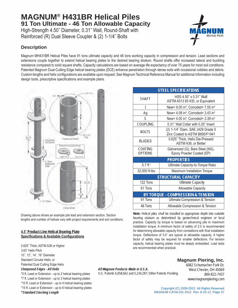
All Magnum Products Made in U.S.A.U.S. Patents 6,058,662 and 5,234,287; Other Patents Pending.
Magnum Piering, Inc.6082 Schumacher Park Dr.
West Chester, OH 45069800-822-7437
www.magnumpiering.com
STEEL SPECIFICATIONS
PROPERTIES
STRUCTURAL CAPACITY
CAPACITY BY TORQUE
Copyright (C) 2009-2012 All Rights ReservedMAGNUM CATALOG 2012 Rev. 8-10-12, Page 37
®
BY TORQUE - COMPRESSION & TENSION
4.5˝ Product Line Helical Bearing PlateSpecifications & Available Configurations
0.625˝ Thick; ASTM A36 or Higher3.63˝ Helix Pitch10˝, 12˝, 14˝, 16˝ DiameterStandard Circular Helix, orPatented Dual Cutting Edge HelixSharpened Edges - All Helix*5 ft. Lead or Extension - up to 2 helical bearing plates*7 ft. Lead or Extension - up to 3 helical bearing plates*10 ft. Lead or Extension - up to 4 helical bearing plates*15 ft. Lead or Extension - up to 6 helical bearing plates* Standard Stocking Length
MAGNUM® H431BR Helical Piles91 Ton Ultimate - 46 Ton Allowable CapacityHigh-Strength 4.50˝ Diameter, 0.31˝ Wall, Round-Shaft withReinforced (R) Dual Sleeve Coupler & (2) 1-1/4˝ Bolts
Magnum MH431BR Helical Piles have 91 tons ultimate capacity and 46 tons working capacity in compression and tension. Lead sections and extensions couple together to extend helical bearing plates to the desired bearing stratum. Round shafts offer increased lateral and buckling resistance compared to solid square shafts. Capacity calculations are based on average life expectancy of over 75 years for most soil conditions. Patented Magnum Dual-Cutting Edge helical bearing plates (DCE) enhance penetration through dense soils with occasional cobbles and debris. Custom lengths and helix configurations are available upon request. See Magnum Technical Reference Manual for additional information including design tools, prescriptive specifications and example plans.
SHAFT
I
Ag
S
COUPLING
BOLTS
BLADES
COATINGOPTIONS
5.7 ft-1
32,000 ft-lbs
122 Tons
61 Tons
91 Tons
46 Tons
New= 9.00 in4, Corroded= 7.55 in4
New= 4.08 in2, Corroded= 3.43 in2
New= 4.00 in3, Corroded= 3.39 in3
0.31˝ Wall Collar with 0.25˝ Insert(2) 1-1/4˝ Diam. SAE J429 Grade 5 Zinc Coated to ASTM B695/F1941
Galvanized (G), Bare Steel (NG),Epoxy Powder Coated (EP)
Ultimate Capacity-to-Torque Ratio
Maximum Installation Torque
Ultimate Capacity
Allowable Capacity
Ultimate Compression & Tension
Allowable Compression & Tension
0.625˝ Thick, Helix Die-PressedASTM A36, or Better
HSS 4.50˝ x 0.31˝ WallASTM A513 65 KSI, or Equivalent
Note: Helical piles shall be installed to appropriate depth into suitable bearing stratum as determined by geotechnical engineer or local practice. Capacity by torque is based on advancing pile to maximum installation torque. A minimum factor of safety of 2.0 is recommended for determining allowable capacity from correlations with final installation torque. Deflections of 0.5˝ are typical at allowable capacity. A higher factor of safety may be required for smaller deflections. For tension capacity, helical bearing plates must be deeply embedded. Load tests are recommended when practical.
Description
Drawing above shows an example pile lead and extension section. Section lengths and number of helices vary with project requirements and soil conditions.

®
All Magnum Products Made in U.S.A.U.S. Patents 6,058,662 and 5,234,287; Other Patents Pending.
Magnum Piering, Inc.6082 Schumacher Park Dr.
West Chester, OH 45069800-822-7437
www.magnumpiering.com
Copyright (C) 2009-2012 All Rights ReservedMAGNUM CATALOG 2012 Rev. 8-10-12, Page 38
STEEL SPECIFICATIONS
PROPERTIES
STRUCTURAL CAPACITY
CAPACITY BY TORQUEBY TORQUE - COMPRESSION & TENSION
5.5˝ Product Line Helical Bearing PlateSpecifications & Available Configurations
0.875˝ Thick; ASTM A36 or Higher3.88˝ Helix Pitch12˝, 16˝, 20˝, 24˝ DiameterStandard Circular Helix, orPatented Dual Cutting Edge HelixSharpened Edges - All Helix*6 ft. Lead or Extension - up to 2 helical bearing plates*10 ft. Lead or Extension - up to 3 helical bearing plates*15 ft. Lead or Extension - up to 5 helical bearing plates* Standard Stocking Length
MAGNUM® MH530B Helical Piles125 Ton Ultimate - 62 Ton AllowableHigh-Strength 5.50˝ Diameter, 0.30˝ Wall, Round-Shaft withRigid Coupler & (3)1-1/2˝ Bolts
Magnum MH530B Helical Piles have 125 tons ultimate capacity and 62 tons working capacity in compression and tension. Lead sections and extensions couple together to extend helical bearing plates to the desired bearing stratum. Round shafts offer increased lateral and buckling resistance compared to solid square shafts. Capacity calculations are based on average life expectancy of over 75 years for most soil conditions. Patented Magnum Dual-Cutting Edge helical bearing plates (DCE) enhance penetration through dense soils with occasional cobbles and debris. Custom lengths and helix configurations are available upon request. See Magnum Technical Reference Manual for additional information including design tools, prescriptive specifications and example plans.
SHAFT
I
AgS
COUPLING
BOLTS
BLADES
COATINGOPTIONS
4.7 ft-1
53,000 ft-lbs
273 Tons
137 Tons
125 Tons
62 Tons
New= 16.62 in4, Corroded= 13.85 in4
New= 4.90 in2, Corroded= 4.09 in2
New= 6.04 in3, Corroded= 5.08 in3
0.325˝ Wall Collar(3) 1-1/2˝ Diam. SAE J429 Grade 5 Zinc Coated to ASTM B695/F1941
Galvanized (G), Bare Steel (NG),Epoxy Powder Coated (EP)
Ultimate Capacity-to-Torque Ratio
Maximum Installation Torque
Ultimate Capacity
Allowable Capacity
Ultimate Compression & Tension
Allowable Compression & Tension
0.875˝ Thick, Helix Die-Pressed True HelixASTM A36, or Better
HSS 5.50” x 0.30” wallAPI Grade P-110, 125 KSI Yield or Equivalent
Note: Helical piles shall be installed to appropriate depth into suitable bearing stratum as determined by geotechnical engineer or local practice. Capacity by torque is based on advancing pile to maximum installation torque. A minimum factor of safety of 2.0 is recommended for determining allowable capacity from correlations with final installation torque. Deflections of 0.50˝ are typical at allowable capacity. A higher factor of safety may be required for smaller deflections. For tension capacity, helical bearing plates must be deeply embedded. Load tests are recommended when practical.
Description
Drawing above shows an example pile lead and extension section. Section lengths and number of helices vary with project requirements and soil conditions.

All Magnum Products Made in U.S.A.U.S. Patents 6,058,662 and 5,234,287; Other Patents Pending.
Magnum Piering, Inc.6082 Schumacher Park Dr.
West Chester, OH 45069800-822-7437
www.magnumpiering.com
STEEL SPECIFICATIONS
PROPERTIES
STRUCTURAL CAPACITY
CAPACITY BY TORQUE
Copyright (C) 2009-2012 All Rights ReservedMAGNUM CATALOG 2012 Rev. 8-10-12, Page 39
®
BY TORQUE - COMPRESSION & TENSION
5.5˝ Product Line Helical Bearing PlateSpecifications & Available Configurations
0.875˝ Thick; ASTM A36 or Higher3.88˝ Helix Pitch12˝, 16˝, 20˝, 24˝ DiameterStandard Circular Helix, orPatented Dual Cutting Edge HelixSharpened Edges - All Helix*6 ft. Lead or Extension - up to 2 helical bearing plates*10 ft. Lead or Extension - up to 3 helical bearing plates*15 ft. Lead or Extension - up to 5 helical bearing plates* Standard Stocking Length
MAGNUM® MH536B Helical Piles195 Ton Ultimate - 98 Ton AllowableHigh-Strength 5.50˝ Diameter, 0.36˝ Wall, Round-Shaft withRigid Coupler & (3)1-1/2˝ Bolts
Magnum MH536B Helical Piles have 195 tons ultimate capacity and 98 tons working capacity in compression and tension. Lead sections and extensions couple together to extend helical bearing plates to the desired bearing stratum. Round shafts offer increased lateral and buckling resistance compared to solid square shafts. Capacity calculations are based on average life expectancy of over 75 years for most soil conditions. Patented Magnum Dual-Cutting Edge helical bearing plates (DCE) enhance penetration through dense soils with occasional cobbles and debris. Custom lengths and helix configurations are available upon request. See Magnum Technical Reference Manual for additional information including design tools, prescriptive specifications and example plans.
SHAFT
I
Ag
S
COUPLING
BOLTS
BLADES
COATINGOPTIONS
4.7 ft-1
83,000 ft-lbs
270 Tons
135 Tons
195 Tons
98 Tons
New= 19.29 in4, Corroded= 16.60 in4
New= 5.81 in2, Corroded= 5.01 in2
New= 7.02 in3, Corroded= 6.09 in3
0.36˝ Wall Collar(3) 1-1/2˝ Diam. SAE J429 Grade 5Zinc Coated to ASTM B695/F1941
Galvanized (G), Bare Steel (NG),Epoxy Powder Coated (EP)
Ultimate Capacity-to-Torque Ratio
Maximum Installation Torque
Ultimate Capacity
Allowable Capacity
Ultimate Compression & Tension
Allowable Compression & Tension
0.875˝ Thick, Helix Die-Pressed True HelixASTM A36, or Better
HSS 5.50˝ x 0.36˝ wallAPI Grade C-95, 100 KSI Min. Yield, or Equivalent
Note: Helical piles shall be installed to appropriate depth into suitable bearing stratum as determined by geotechnical engineer or local practice. Capacity by torque is based on advancing pile to maximum installation torque. A minimum factor of safety of 2.0 is recommended for determining allowable capacity from correlations with final installation torque. Deflections of 0.50˝ are typical at allowable capacity. A higher factor of safety may be required for smaller deflections. For tension capacity, helical bearing plates must be deeply embedded. Load tests are recommended when practical.
Description
Drawing above shows an example pile lead and extension section. Section lengths and number of helices vary with project requirements and soil conditions.

®
All Magnum Products Made in U.S.A.U.S. Patents 6,058,662 and 5,234,287; Other Patents Pending.
Magnum Piering, Inc.6082 Schumacher Park Dr.
West Chester, OH 45069800-822-7437
www.magnumpiering.com
Copyright (C) 2009-2012 All Rights ReservedMAGNUM CATALOG 2012 Rev. 8-10-12, Page 40
STEEL SPECIFICATIONS
PROPERTIES
STRUCTURAL CAPACITY
CAPACITY BY TORQUEBY TORQUE - COMPRESSION & TENSIONBY TORQUE - COMPRESSION & TENSION
6˝ Product Line Helical Bearing PlateSpecifications & Available Configurations
0.875˝ Thick; ASTM A36 or Higher3.88˝ Blade Pitch12˝, 16˝, 20˝, 24˝ DiameterStandard Circular Helix, orPatented Dual Cutting Edge HelixSharpened Edges - All Helix*6 ft. Lead or Extension - up to 2 helical bearing plates*10 ft. Lead or Extension - up to 3 helical bearing plates*15 ft. Lead or Extension - up to 5 helical bearing plates* Standard Stocking Length
MAGNUM® MH625B Helical Piles92 Ton Ultimate - 46 Ton AllowableHigh-Strength 5.72˝ Diameter, 0.25˝ Wall, Round-Shaft withRigid Coupler & (3)1-1/2˝ Bolts
Magnum MH625B Helical Piles have 92 tons ultimate capacity and 46 tons working capacity in compression and tension. Lead sections and extensions couple together to extend helical bearing plates to the desired bearing stratum. Round shafts offer increased lateral and buckling resistance compared to solid square shafts. Capacity calculations are based on average life expectancy of over 75 years for most soil conditions. Patented Magnum Dual-Cutting Edge helical bearing plates (DCE) enhance penetration through dense soils with occasional cobbles and debris. Custom lengths and helix configurations are available upon request. See Magnum Technical Reference Manual for additional information including design tools, prescriptive specifications and example plans.
SHAFT
I
AgS
COUPLING
BOLTS
BLADES
COATINGOPTIONS
4.6 ft-1
40,000 ft-lbs
128 Tons
64 Tons
92 Tons
46 Tons
New= 16.12 in4, Corroded= 12.90 in4
New= 4.30 in2, Corroded= 3.44 in2
New= 5.63 in3, Corroded= 4.55 in3
0.46˝ Wall Collar(3) 1-1/2˝ Diam. SAE J429 Grade 5Zinc Coated to ASTM B695/F1941
Galvanized (G), Bare Steel (NG),Epoxy Powder Coated (EP)
Ultimate Capacity-to-Torque Ratio
Maximum Installation Torque
Ultimate Capacity
Allowable Capacity
Ultimate Compression & Tension
Allowable Compression & Tension
0.875” Thick, Helix Die-PressedASTM A36, or Better
HSS 5.72˝ x 0.25˝ wallASTM A513 65 KSI, or Equivalent
Note: Helical piles shall be installed to appropriate depth into suitable bearing stratum as determined by geotechnical engineer or local practice. Capacity by torque is based on advancing pile to maximum installation torque. A minimum factor of safety of 2.0 is recommended for determining allowable capacity from correlations with final installation torque. Deflections of 0.5˝ are typical at allowable capacity. A higher factor of safety may be required for smaller deflections. For tension capacity, helical bearing plates must be deeply embedded. Load tests are recommended when practical.
Description
Drawing above shows an example pile lead and extension section. Section lengths and number of helices vary with project requirements and soil conditions.

All Magnum Products Made in U.S.A.U.S. Patents 6,058,662 and 5,234,287; Other Patents Pending.
Magnum Piering, Inc.6082 Schumacher Park Dr.
West Chester, OH 45069800-822-7437
www.magnumpiering.com
STEEL SPECIFICATIONS
PROPERTIES
STRUCTURAL CAPACITY
CAPACITY BY TORQUE
Copyright (C) 2009-2012 All Rights ReservedMAGNUM CATALOG 2012 Rev. 8-10-12, Page 41
®
BY TORQUE - COMPRESSION & TENSION
6˝ Product Line Helical Bearing Plate Specifications & Available Configurations
0.875˝ Thick; ASTM A36 or Higher3.88˝ Blade Pitch12˝, 16˝, 20˝, 24˝ DiameterStandard Circular Helix, orPatented Dual Cutting Edge HelixSharpened Edges - All Helix*6 ft. Lead or Extension - up to 2 helical bearing plates*10 ft. Lead or Extension - up to 3 helical bearing plates*15 ft. Lead or Extension - up to 5 helical bearing plates* Standard Stocking Length
MAGNUM® MH625BR Helical Piles104 Ultimate - 52 Ton Allowable CapacityHigh-Strength 5.72˝ Diameter, 0.25˝ Wall, Round-Shaft withReinforced (R) Dual Sleeve Coupler & (3) 1-1/2˝ Bolts
Magnum MH625BR Helical Piles have 104 tons ultimate capacity and 52 tons working capacity in compression and tension. Lead sections and extensions couple together to extend helical bearing plates to the desired bearing stratum. Round shafts offer increased lateral and buckling resistance compared to solid square shafts. Capacity calculations are based on average life expectancy of over 75 years for most soil conditions. Patented Magnum Dual-Cutting Edge helical bearing plates (DCE) enhance penetration through dense soils with occasional cobbles and debris. Custom lengths and helix configurations are available upon request. See Magnum Technical Reference Manual for additional information including design tools, prescriptive specifications and example plans.
SHAFT
I
Ag
S
COUPLING
BOLTS
BLADES
COATINGOPTIONS
4.6 ft-1
45,000 ft-lbs
128 Tons
64 Tons
104 Tons
52 Tons
New= 16.12 in4, Corroded= 12.90 in4
New= 4.30 in2, Corroded= 3.44 in2
New= 5.63 in3, Corroded= 4.55 in3
0.46˝ Wall Collar with 0.25˝ Wall Insert
(3) 1-1/2˝ Diam. SAE J429 Grade 5Zinc Coated to ASTM B695/F1941
Galvanized (G), Bare Steel (NG),Epoxy Powder Coated (EP)
Ultimate Capacity-to-Torque Ratio
Maximum Installation Torque
Ultimate Capacity
Allowable Capacity
Ultimate Compression & Tension
Allowable Compression & Tension
0.875˝ Thick, Helix Die-PressedASTM A36, or Better
HSS 5.72˝ x 0.25˝ wallASTM A513 65 KSI, or Equivalent
Note: Helical piles shall be installed to appropriate depth into suitable bearing stratum as determined by geotechnical engineer or local practice. Capacity by torque is based on advancing pile to maximum installation torque. A minimum factor of safety of 2.0 is recommended for determining allowable capacity from correlations with final installation torque. Deflections of 0.5˝ are typical at allowable capacity. A higher factor of safety may be required for smaller deflections. For tension capacity, helical bearing plates must be deeply embedded. Load tests are recommended when practical.
Description
Drawing above shows an example pile lead and extension section. Section lengths and number of helices vary with project requirements and soil conditions.

®
All Magnum Products Made in U.S.A.U.S. Patents 6,058,662 and 5,234,287; Other Patents Pending.
Magnum Piering, Inc.6082 Schumacher Park Dr.
West Chester, OH 45069800-822-7437
www.magnumpiering.com
Copyright (C) 2009-2012 All Rights ReservedMAGNUM CATALOG 2012 Rev. 8-10-12, Page 42
STEEL SPECIFICATIONS
PROPERTIES
STRUCTURAL CAPACITY
CAPACITY BY TORQUEBY TORQUE - COMPRESSION & TENSION
6˝ Product Line Helical Bearing PlateSpecifications & Available Configurations
0.875˝ Thick; ASTM A36 or Higher3.00˝ Blade Pitch12˝, 16˝, 20˝, 24˝ DiameterStandard Circular Helix, orPatented Dual Cutting Edge HelixSharpened Edges - All Helix*6 ft. Lead or Extension - up to 2 helical bearing plates*10 ft. Lead or Extension - up to 3 helical bearing plates*15 ft. Lead or Extension - up to 5 helical bearing plates* Standard Stocking Length
MAGNUM® MH637B Helical Piles124 Ton Ultimate - 62 Ton Allowable CapacityHigh-Strength 5.72˝ Diameter, 0.37˝ Wall, Round-Shaft withRigid Coupler & (3) 1-1/2˝ Bolts
Magnum MH637B Helical Piles have 124 tons ultimate capacity and 62 tons working capacity in compression and tension. Lead sections and extensions couple together to extend helical bearing plates to the desired bearing stratum. Round shafts offer increased lateral and buckling resistance compared to solid square shafts. Capacity calculations are based on average life expectancy of over 75 years for most soil conditions. Patented Magnum Dual-Cutting Edge helical bearing plates (DCE) enhance penetration through dense soils with occasional cobbles and debris. Custom lengths and helix configurations are available upon request. See Magnum Technical Reference Manual for additional information including design tools, prescriptive specifications and example plans.
SHAFT
I
AgS
COUPLING
BOLTS
BLADES
COATINGOPTIONS
4.6 ft-1
54,000 ft-lbs
199 Tons
100 Tons
124 Tons
62 Tons
New= 22.38 in4, Corroded= 19.35 in4
New= 6.22 in2, Corroded= 5.38 in2
New= 7.82 in3, Corroded= 6.82 in3
0.46˝ Wall Collar(3) 1-1/2˝ Diam. SAE J429 Grade 5Zinc Coated to ASTM B695/F1941
Galvanized (G), Bare Steel (NG),Epoxy Powder Coated (EP)
Ultimate Capacity-to-Torque Ratio
Maximum Installation Torque
Ultimate Capacity
Allowable Capacity
Ultimate Compression & Tension
Allowable Compression & Tension
0.875˝ Thick, Helix Die-PressedASTM A36, or Better
HSS 5.72˝ x 0.37˝ wallASTM A513 65 KSI, or Equivalent
Note: Helical piles shall be installed to appropriate depth into suitable bearing stratum as determined by geotechnical engineer or local practice. Capacity by torque is based on advancing pile to maximum installation torque. A minimum factor of safety of 2.0 is recommended for determining allowable capacity from correlations with final installation torque. Deflections of 0.5˝ are typical at allowable capacity. A higher factor of safety may be required for tolerable deflections. For tension capacity, helical bearing plates must be deeply embedded. Loadtests are recommended when practical.
Description
Drawing above shows an example pile lead and extension section. Section lengths and number of helices vary with project requirements and soil conditions.

All Magnum Products Made in U.S.A.U.S. Patents 6,058,662 and 5,234,287; Other Patents Pending.
Magnum Piering, Inc.6082 Schumacher Park Dr.
West Chester, OH 45069800-822-7437
www.magnumpiering.com
STEEL SPECIFICATIONS
PROPERTIES
STRUCTURAL CAPACITY
CAPACITY BY TORQUE
Copyright (C) 2009-2012 All Rights ReservedMAGNUM CATALOG 2012 Rev. 8-10-12, Page 43
®
BY TORQUE - COMPRESSION & TENSION
6˝ Product Line Helical Bearing Plate Specifications & Available Configurations
0.875˝ Thick; ASTM A36 or Higher3.00˝ Blade Pitch12˝, 16˝, 20˝, 24˝ DiameterStandard Circular Helix, orPatented Dual Cutting Edge HelixSharpened Edges - All Helix*6 ft. Lead or Extension - up to 2 helical bearing plates*10 ft. Lead or Extension - up to 3 helical bearing plates*15 ft. Lead or Extension - up to 5 helical bearing plates* Standard Stocking Length
MAGNUM® MH637BR Helical Piles150 Ton Ultimate - 75 Ton AllowableHigh-Strength 5.72˝ Diameter, 0.37˝ Wall, Round-Shaft withDual-Sleeve Reinforced (R) Coupler & (3) 1-1/2˝ Bolts
Magnum MH637BR Helical Piles have 150 tons ultimate capacity and 75 tons working capacity in compression and tension. Lead sections and extensions couple together to extend helical bearing plates to the desired bearing stratum. Round shafts offer increased lateral and buckling resistance compared to solid square shafts. Capacity calculations are based on average life expectancy of over 75 years for most soil conditions. Patented Magnum Dual-Cutting Edge helical bearing plates (DCE) enhance penetration through dense soils with occasional cobbles and debris. Custom lengths and helix configurations are available upon request. See Magnum Technical Reference Manual for additional information including design tools, prescriptive specifications and example plans.
SHAFT
I
Ag
S
COUPLING
BOLTS
BLADES
COATINGOPTIONS
4.6 ft-1
65,000 ft-lbs
199 Tons
100 Tons
150 Tons
75 Tons
New= 22.38 in4, Corroded= 19.35 in4
New= 6.22 in2, Corroded= 5.38 in2
New= 7.82 in3, Corroded= 6.82 in3
0.46˝ Wall Collar
(3) 1-1/2˝ Diam. SAE J429 Grade 5Zinc Coated to ASTM B695/F1941
Galvanized (G), Bare Steel (NG),Epoxy Powder Coated (EP)
Ultimate Capacity-to-Torque Ratio
Maximum Installation Torque
Ultimate Capacity
Allowable Capacity
Ultimate Compression & Tension
Allowable Compression & Tension
0.875˝ Thick, Helix Die-PressedASTM A36, or Better
HSS 5.72˝ x 0.37˝ wallASTM A513 65 KSI, or Equivalent
Note: Helical piles shall be installed to appropriate depth into suitable bearing stratum as determined by geotechnical engineer or local practice. Capacity by torque is based on advancing pile to maximum installation torque. A minimum factor of safety of 2.0 is recommended for determining allowable capacity from correlations with final installation torque. Deflections of 0.5˝ are typical at allowable capacity. A higher factor of safety may be required for smaller deflections. For tension capacity, helical bearing plates must be deeply embedded. Load tests are recommended when practical.
Description
Drawing above shows an example pile lead and extension section. Section lengths and number of helices vary with project requirements and soil conditions.

®
All Magnum Products Made in U.S.A.U.S. Patents 6,058,662 and 5,234,287; Other Patents Pending.
Magnum Piering, Inc.6082 Schumacher Park Dr.
West Chester, OH 45069800-822-7437
www.magnumpiering.com
Copyright (C) 2009-2012 All Rights ReservedMAGNUM CATALOG 2012 Rev. 8-10-12, Page 44
STEEL SPECIFICATIONS
PROPERTIES
STRUCTURAL CAPACITY
CAPACITY BY TORQUEBY TORQUE - COMPRESSION & TENSION
6˝ Product Line Helical Bearing PlateSpecifications & Available Configurations
0.875˝ Thick; ASTM A36 or Higher3.00˝ Blade Pitch12˝, 16˝, 20˝, 24˝ DiameterStandard Circular Helix, orPatented Dual Cutting Edge HelixSharpened Edges - All Helix*6 ft. Lead or Extension - up to 2 helical bearing plates*10 ft. Lead or Extension - up to 3 helical bearing plates*15 ft. Lead or Extension - up to 5 helical bearing plates* Standard Stocking Length
MAGNUM® MH646B Helical Piles152 Ton Ultimate - 76 Ton Allowable CapacityHigh-Strength 5.72˝ Diameter, 0.46˝ Wall, Round-Shaft withRigid Coupler & (3) 1-1/2˝ Bolts
Magnum MH646B Helical Piles have 152 tons ultimate capacity and 76 tons working capacity in compression and tension. Lead sections and extensions couple together to extend helical bearing plates to the desired bearing stratum. Round shafts offer increased lateral and buckling resistance compared to solid square shafts. Capacity calculations are based on average life expectancy of over 75 years for most soil conditions. Patented Magnum Dual-Cutting Edge helical bearing plates (DCE) enhance penetration through dense soils with occasional cobbles and debris. Custom lengths and helix configurations are available upon request. See Magnum Technical Reference Manual for additional information including design tools, prescriptive specifications and example plans.
SHAFT
I
AgS
COUPLING
BOLTS
BLADES
COATINGOPTIONS
4.6 ft-1
66,000 ft-lbs
250 Tons
125 Tons
152 Tons
76 Tons
New= 26.52 in4, Corroded= 23.61 in4
New= 7.60 in2, Corroded= 6.78 in2
New= 9.27 in3, Corroded= 8.33 in3
0.46˝ Wall Collar(3) 1-1/2˝ Diam. SAE J429 Grade 5Zinc Coated to ASTM B695/F1941
Galvanized (G), Bare Steel (NG),Epoxy Powder Coated (EP)
Ultimate Capacity-to-Torque Ratio
Maximum Installation Torque
Ultimate Capacity
Allowable Capacity
Ultimate Compression & Tension
Allowable Compression & Tension
0.875” Thick, Helix Die-PressedASTM A36, or Better
HSS 5.72˝ x 0.46˝ wallASTM A513 65 KSI, or Equivalent
Note: Helical piles shall be installed to appropriate depth into suitable bearing stratum as determined by geotechnical engineer or local practice. Capacity by torque is based on advancing pile to maximum installation torque. A minimum factor of safety of 2.0 is recommended for determining allowable capacity from correlations with final installation torque. Deflections of 0.5˝ are typical at allowable capacity. A higher factor of safety may be required for smaller deflections. For tension capacity, helical bearing plates must be deeply embedded. Load tests are recommended when practical.
Description
Drawing above shows an example pile lead and extension section. Section lengths and number of helices vary with project requirements and soil conditions.

All Magnum Products Made in U.S.A.U.S. Patents 6,058,662 and 5,234,287; Other Patents Pending.
Magnum Piering, Inc.6082 Schumacher Park Dr.
West Chester, OH 45069800-822-7437
www.magnumpiering.com
STEEL SPECIFICATIONS
PROPERTIES
STRUCTURAL CAPACITY
CAPACITY BY TORQUE
Copyright (C) 2009-2012 All Rights ReservedMAGNUM CATALOG 2012 Rev. 8-10-12, Page 45
®
BY TORQUE - COMPRESSION & TENSION
6˝ Product Line Helical Bearing Plate Specifications & Available Configurations
0.875˝ Thick; ASTM A36 or Higher3.00˝ Blade Pitch12˝, 16˝, 20˝, 24˝ DiameterStandard Circular Helix, orPatented Dual Cutting Edge HelixSharpened Edges - All Helix*6 ft. Lead or Extension - up to 2 helical bearing plates*10 ft. Lead or Extension - up to 3 helical bearing plates*15 ft. Lead or Extension - up to 5 helical bearing plates* Standard Stocking Length
MAGNUM® MH646BR Helical Piles184 Ton Ultimate - 92 Ton Allowable CapacityHigh-Strength 5.72˝ Diameter, 0.46˝ Wall, Round-Shaft withDual-Sleeve Reinforced (R) Coupler & (3) 1-1/2˝ Bolts
Magnum MH646BR Helical Piles have 184 tons ultimate capacity and 92 tons working capacity in compression and tension. Lead sections and extensions couple together to extend helical bearing plates to the desired bearing stratum. Round shafts offer increased lateral and buckling resistance compared to solid square shafts. Capacity calculations are based on average life expectancy of over 75 years for most soil conditions. Patented Magnum Dual-Cutting Edge helical bearing plates (DCE) enhance penetration through dense soils with occasional cobbles and debris. Custom lengths and helix configurations are available upon request. See Magnum Technical Reference Manual for additional information including design tools, prescriptive specifications and example plans.
SHAFT
I
Ag
S
COUPLING
BOLTS
BLADES
COATINGOPTIONS
4.6 ft-1
80,000 ft-lbs
250 Tons
125 Tons
184 Tons
92 Tons
New= 26.52 in4, Corroded= 23.61 in4
New= 7.60 in2, Corroded= 6.78 in2
New= 9.27 in3, Corroded= 8.33 in3
0.46˝ Wall Collar with 0.46˝ Insert(3) 1-1/2˝ Diam. SAE J429 Grade 5Zinc Coated to ASTM B695/F1941
Galvanized (G), Bare Steel (NG),Epoxy Powder Coated (EP)
Ultimate Capacity-to-Torque Ratio
Maximum Installation Torque
Ultimate Capacity
Allowable Capacity
Ultimate Compression & Tension
Allowable Compression & Tension
0.875˝ Thick, Helix Die-PressedASTM A36, or Better
HSS 5.72˝ x 0.46˝ wallASTM A513 65 KSI, or Equivalent
Note: Helical piles shall be installed to appropriate depth into suitable bearing stratum as determined by geotechnical engineer or local practice. Capacity by torque is based on advancing pile to maximum installation torque. A minimum factor of safety of 2.0 is recommended for determining allowable capacity from correlations with final installation torque. Deflections of 0.5˝ are typical at allowable capacity. A higher factor of safety may be required for smaller deflections. For tension capacity, helical bearing plates must be deeply embedded. Load tests are recommended when practical.
Description
Drawing above shows an example pile lead and extension section. Section lengths and number of helices vary with project requirements and soil conditions.

®
All Magnum Products Made in U.S.A.U.S. Patents 6,058,662 and 5,234,287; Other Patents Pending.
Magnum Piering, Inc.6082 Schumacher Park Dr.
West Chester, OH 45069800-822-7437
www.magnumpiering.com
Copyright (C) 2009-2012 All Rights ReservedMAGNUM CATALOG 2012 Rev. 8-10-12, Page 46
STEEL SPECIFICATIONS
PROPERTIES
STRUCTURAL CAPACITY
CAPACITY BY TORQUEGEOTECHNICAL CAPACITY BY TORQUE
8˝ Product Line Helical Bearing PlateSpecifications & Available Configurations
0.875˝ Thick; ASTM A36 or Higher3.00˝ Blade Pitch16˝, 20˝, 24˝ DiameterStandard Circular Helix, orPatented Dual Cutting Edge HelixSharpened Edges - All Helix*6 ft. Lead or Extension - up to 1 helical bearing plates*10 ft. Lead or Extension - up to 2 helical bearing plates*15 ft. Lead or Extension - up to 3 helical bearing plates* Standard Stocking Length
MAGNUM® MH832B Helical Piles132 Ton Ultimate - 66 Ton AllowableHigh-Strength 8.63˝ Diameter, 0.32˝ Wall, Round-Shaft withRigid Coupler & (3)1-1/2˝ Bolts
Magnum MH832B Helical Piles have 132 tons ultimate capacity and 66 tons working capacity in compression and tension. Lead sections and extensions couple together to extend helical bearing plates to the desired bearing stratum. Round shafts offer increased lateral and buckling resistance compared to solid square shafts. Capacity calculations are based on average life expectancy of over 75 years for most soil conditions. Patented Magnum Dual-Cutting Edge helical bearing plates (DCE) enhance penetration through dense soils with occasional cobbles and debris. Custom lengths and helix configurations are available upon request. See Magnum Technical Reference Manual for additional information including design tools, prescriptive specifications and example plans.
SHAFT
I
AgS
COUPLING
BOLTS
BLADES
COATINGOPTIONS
3.1 ft-1
85,000 ft-lbs
175 Tons
88 Tons
132 Tons
66 Tons
New= 72.09 in4, Corroded= 60.84 in4
New= 8.35 in2, Corroded= 7.05 in2
New= 16.72 in3, Corroded= 14.19 in3
0.375˝ Wall Collar(3) 1-1/2˝ Diam. SAE J429 Grade 5Zinc Coated to ASTM B695/F1941
Galvanized (G), Bare Steel (NG),Epoxy Powder Coated (EP)
Ultimate Capacity-to-Torque Ratio
Maximum Installation Torque
Ultimate Capacity
Allowable Capacity
Ultimate Compression & Tension
Allowable Compression & Tension
0.875” Thick, Helix Die-PressedASTM A36, or Better
HSS 8.63˝ x 0.32˝ wallASTM A513 65 KSI, or Equivalent
Note: Helical piles shall be installed to appropriate depth into suitable bearing stratum as determined by geotechnical engineer or local practice. Capacity by torque is based on advancing pile to maximum installation torque. A minimum factor of safety of 2.0 is recommended for determining allowable capacity from correlations with final installation torque. Deflections of 0.5˝ are typical at allowable capacity. A higher factor of safety may be required for smaller deflections. For tension capacity, helical bearing plates must be deeply embedded. Load tests are recommended when practical.
Description
Drawing above shows an example pile lead and extension section. Section lengths and number of helices vary with project requirements and soil conditions.
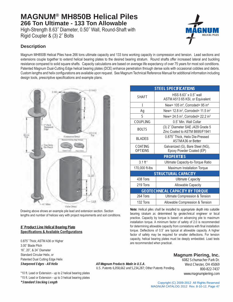
All Magnum Products Made in U.S.A.U.S. Patents 6,058,662 and 5,234,287; Other Patents Pending.
Magnum Piering, Inc.6082 Schumacher Park Dr.
West Chester, OH 45069800-822-7437
www.magnumpiering.com
STEEL SPECIFICATIONS
PROPERTIES
STRUCTURAL CAPACITY
CAPACITY BY TORQUE
Copyright (C) 2009-2012 All Rights ReservedMAGNUM CATALOG 2012 Rev. 8-10-12, Page 47
®
GEOTECHNICAL CAPACITY BY TORQUE
MAGNUM® MH850B Helical Piles266 Ton Ultimate - 133 Ton AllowableHigh-Strength 8.63˝ Diameter, 0.50˝ Wall, Round-Shaft withRigid Coupler & (3) 2˝ Bolts
Description
SHAFT
I
Ag
S
COUPLING
BOLTS
BLADES
COATINGOPTIONS
3.1 ft-1
170,000 ft-lbs
438 Tons
219 Tons
264 Tons
132 Tons
New= 105 in4, Corroded= 95 in4
New= 12.8 in2, Corroded= 11.5 in2
New= 24.5 in3, Corroded= 22.2 in3
0.5˝ Min. Wall Collar(3) 2˝ Diameter SAE J429 Grade 5Zinc Coated to ASTM B695/F1941
Galvanized (G), Bare Steel (NG),Epoxy Powder Coated (EP)
Ultimate Capacity-to-Torque Ratio
Maximum Installation Torque
Ultimate Capacity
Allowable Capacity
Ultimate Compression & Tension
Allowable Compression & Tension
0.875˝ Thick, Helix Die-PressedASTM A36 or Better
HSS 8.63˝ x 0.5˝ wallASTM A513 65 KSI, or Equivalent
Drawing above shows an example pile lead and extension section. Section lengths and number of helices vary with project requirements and soil conditions.
Magnum MH850B Helical Piles have 266 tons ultimate capacity and 133 tons working capacity in compression and tension. Lead sections and extensions couple together to extend helical bearing plates to the desired bearing stratum. Round shafts offer increased lateral and buckling resistance compared to solid square shafts. Capacity calculations are based on average life expectancy of over 75 years for most soil conditions. Patented Magnum Dual-Cutting Edge helical bearing plates (DCE) enhance penetration through dense soils with occasional cobbles and debris. Custom lengths and helix configurations are available upon request. See Magnum Technical Reference Manual for additional information including design tools, prescriptive specifications and example plans.
8˝ Product Line Helical Bearing PlateSpecifications & Available Configurations
0.875˝ Thick; ASTM A36 or Higher3.00˝ Blade Pitch16˝, 20˝, & 24˝ DiameterStandard Circular Helix, orPatented Dual Cutting Edge HelixSharpened Edges - All Helix
*10 ft. Lead or Extension - up to 2 helical bearing plates*15 ft. Lead or Extension - up to 3 helical bearing plates* Standard Stocking Length
Note: Helical piles shall be installed to appropriate depth into suitable bearing stratum as determined by geotechnical engineer or local practice. Capacity by torque is based on advancing pile to maximum installation torque. A minimum factor of safety of 2.0 is recommended for determining allowable capacity from correlations with final installation torque. Deflections of 0.5˝ are typical at allowable capacity. A higher factor of safety may be required for smaller deflections. For tension capacity, helical bearing plates must be deeply embedded. Load tests are recommended when practical.

Magnum Piering, Inc.6082 Schumacher Park Dr.
West Chester, OH 45069800-822-7437
www.magnumpiering.comAll Magnum Products Made in U.S.A.
U.S. Patents 6,058,662 and 5,234,287; Other Patents Pending.Copyright (C) 2009-2012 All Rights Reserved
MAGNUM CATALOG 2012 Rev. 8-10-12, Page 48
MAGNUM PIERING® Helical Soil NailsContinuous Bonded Helical Anchors for Soil ReinforcementUsed in Earth Retention and Slope Stabilization
Description
As can be seen in the figure to the right, soil nailing is the process of using helical shafts to reinforce slopes and blocks of soil for earth retention and stabilization. Helical soil nails have helical bearing plates spaced along the entire length of the shaft for continuous bonding with the soil. As opposed to grouted anchors which are generally 4 to 6 inches in diameter, helical soil nails mobilize a bonded diameter that is 8 or 10 inches in diameter for a greater reinforcing effect. Soil nailing permits the use of relatively thin shotcrete facing or steel mesh to prevent raveling between nails as opposed to the heavy reinforced facing required for soil anchor walls. Since helical soil nails are intended for earth reinforcement, the termination criteria for the anchors is based on length as opposed to minimum installation torque. Soil nail lengths then are fixed length (typically 0.7 to 0.8 times the slope/wall height). Fixed length allows for the shafts to be manufactured with an integrated thread bar adapter. There is no need to cut-off and re-drill the shaft. Helical soil nails have many advantages over traditional grouted soil nails. Installation is very rapid. There are no issues with caving soils and/or ground water, and there is no waiting for grout to set.
SPECIFICATIONS
DESIGNATIONSHAFT
DIAMETERHELIX
DIAMETER
CORRODEDGROSS AREA
OF SHAFT
MAX.ALLOWABLE
TENSILE STRENGTH
MAX.ALLOWABLE
SHEAR STRENGTH
MHL313BN12K8D8D8D8D8DG 3˝ 8˝ 1.1 IN2 11 TONS 5 TONS
MHL313BN12K10D10D10D10D10DG 3˝ 10˝ 1.1 IN2 11 TONS 5 TONS
Note: Specification table provides two examples of helical soil nail sizes. Other lengths and sizes available.
from Perko (2009)Helical Piles: A Practical Guide to Design and Installation

®
Copyright (C) 2009-2012 All Rights ReservedMAGNUM CATALOG 2012 Rev. 8-10-12, Page 49
MA
GN
UM
PIERIN
G, IN
C.
s e c t i o n 3
STEEL PILE CAPS

Copyright (C) 2009-2012 All Rights ReservedMAGNUM CATALOG 2012 Rev. 8-10-12, Page 50
Mag
num
® B
eari
ng P
late
Cap
Pro
duct
Num
ber
Spe
cific
atio
n Le
gend
®
Expl
anat
ion:
The
Mag
num
Bea
ring
Plat
e C
ap p
rodu
ct n
umbe
r abo
ve M
HC
1300
-4L9
9B1G
is fo
r a C
ap w
ith 4
.6˝ i
nsid
e di
amet
er c
olla
r tub
e w
ith a
9˝ l
ong
by 9
˝ wid
e pl
ate
with
0.5
˝ thi
ckne
ss,
a Bo
lted
conn
ectio
n, a
nd th
e su
rface
pre
para
tion
is G
alva
nize
d.
Not
e: S
ee “M
agnu
m P
ierin
g Be
arin
g Pl
ate
Cap
Spe
cific
atio
ns” t
able
on
next
pag
e fo
r det
aile
d in
form
atio
n. S
peci
ficat
ion
info
rmat
ion
is a
lso
avai
labl
e at
ww
w.m
agnu
mpi
erin
g.co
m
Mag
num
Pie
ring,
Inc.
ISO
900
1:20
08C
ertifi
ed
Cap for Round-Shaft Helical Piles (M
HC) or
Cap for Square-Shaft H
elical Piles (MSC)
Unique Numeric Designation for Bearing Plate Caps
Fits Shaft Diameter (2
)=2.88˝, (3)=3.0˝, (3
5)=3.5˝ , (4)=4.5˝
(5)=5.5˝, (6
)=5.72˝, (8)=8.63˝, o
r
Shaft D
imension (150)=1.50˝ SQR, (175)=1.75˝ SQR
Plate Length (5˝, 6˝, 8
˝, 9˝, 1
0˝, 11˝) -
Custom Sizes Available
Plate Width (5˝, 6˝, 8
˝, 9˝, 1
0˝, 11˝) -
Custom Sizes Available
(G) Galvanized, (NG) Non-Galvanized, or (E
P) Epoxy Powder Coated
Pile Shaft Connection Type (B or B1)=Single Bolt,
(BR2 or B2)=Double Bolt, (
B3)=Triple Bolt
Plate Thickness (J)=1/4˝, (K)=3/8˝, (L
)=1/2˝, (M)=5/8˝, (N
)=3/4˝
(O)=7/8˝, (P
)=1˝
Part
No.
MH
C13
00-
4L
99
B1
G

Copyright (C) 2009-2012 All Rights ReservedMAGNUM CATALOG 2012 Rev. 8-10-12, Page 51
Minimum Concrete Cover to Obtain Rated Capacitiesfor MAGNUM® Bearing Plate Caps2
Notes:1 Code minimum per IBC chapter 18.2 Design all concrete pile caps in accordance to ACI 318 Chapter 22 and IBC Chapter 18. Punching shear area is based upon dimensions (dc and dt) on all four sides of the steel cap edges. Assumes uncracked concrete per ACI Chapter 22.
Bearing Plate Cap2500 psi Conc. 4000 psi Conc.
dc (in) dt (in) dc (in) dt (in)
MHC1300-2J55B 16 16 12 12
MHC1300-3J55B 26 22 19 16
MHC1300-3K66BR1 36 26 28 17
MHC1300-3L6565BR2 32 32 24 24
MHC1300-35K66BR 36 26 28 17
MHC1300-4L88B1 49 18 37 12
MHC1300-4L88B2 49 36 37 27
MHC1300-6N99B1 78 15 60 13
MHC1300-5N99B3 78 45 60 40
MAGNUM® Bearing Plate CapApplication Guide for Punching ShearStructural Plain Concrete
®
dc
dt
5'-6" MINIMUMPER CRSI
DESIGN HANDBOOK 2008
5'-6
" MIN
IMU
MP
ER
CR
SI
HA
ND
BO
OK
200
8
TYPICAL PILE CAP4-PILE ARRANGEMENT SHOWN
dt
de
TENSION COMPRESSION
SHEARPERIMETER
PUNCHING
de
COL.
TYPICAL SECTION4-PILE ARRANGEMENT SHOWN
VAR
IES
COLUMN REACTION
Smin = 3ftor 2 x (dt or dc)
or 3 x Ave Helix Dia.
CONDITION CONDITION
dc
dt
5'-6" MINIMUMPER CRSI
DESIGN HANDBOOK 2008
5'-6
" MIN
IMU
MP
ER
CR
SI
HA
ND
BO
OK
200
8
TYPICAL PILE CAP4-PILE ARRANGEMENT SHOWN
dt
de
TENSION COMPRESSION
SHEARPERIMETER
PUNCHING
COL.
TYPICAL SECTION4-PILE ARRANGEMENT SHOWN
VAR
IES
COLUMN REACTION
Smin = 3ftor 2 x (dt or dc)
or 3 x Ave Helix Dia.
CONDITION CONDITION
dc
de
2" P
ER
AC
I
dc
dt
dt
PILE TENSION PILE COMPRESSION
SHEARPERIMETER
PUNCHING
COL.
VAR
IES
COLUMN REACTION
CONDITION CONDITION
de
2" P
ER
AC
I
w w
dc
dt
dt
TENSION COMPRESSION
SHEARPERIMETER
PUNCHING
COL.
VAR
IES
COLUMN REACTION
CONDITION CONDITION
w w dc

Copyright (C) 2009-2012 All Rights ReservedMAGNUM CATALOG 2012 Rev. 8-10-12, Page 52
Minimum Concrete Cover to Obtain Rated Capacitiesfor MAGNUM® Bearing Plate Caps2
Notes:1 Code minimum per IBC chapter 18.2 Design all concrete pile caps and reinforcing in accordance to the CRSI Design Handbook, 2008. Per CRSI, minimum edge distance (de) is 15 inches up to 60 ton piles and 21 inches up to 120 ton piles. Punching shear area is based upon dimensions (dc and dt) on all four sides of pile caps.
Bearing Plate Cap2500 psi Conc. 4000 psi Conc.
dc (in) dt (in) dc (in) dt (in)
MHC1300-2J55B 8 8 41 41
MHC1300-3J55B 13 11 8 6
MHC1300-3K66BR1 16 9 12 6
MHC1300-3L6565BR2 14 14 10 10
MHC1300-35K66BR 16 9 12 6
MHC1300-4L88B1 22 6 16 41
MHC1300-4L88B2 22 16 16 11
MHC1300-6N99B1 32 41 23 41
MHC1300-5N99B3 32 20 23 14
MAGNUM® Bearing Plate CapApplication Guide for Punching ShearReinforced Concrete
®
dc
dt
5'-6" MINIMUMPER CRSI
DESIGN HANDBOOK 2008
5'-6
" MIN
IMU
MP
ER
CR
SI
HA
ND
BO
OK
200
8
TYPICAL PILE CAP4-PILE ARRANGEMENT SHOWN
dt
de
TENSION COMPRESSION
SHEARPERIMETER
PUNCHING
de
COL.
TYPICAL SECTION4-PILE ARRANGEMENT SHOWN
VAR
IES
COLUMN REACTION
Smin = 3ftor 2 x (dt or dc)
or 3 x Ave Helix Dia.
CONDITION CONDITION
dc
dt
5'-6" MINIMUMPER CRSI
DESIGN HANDBOOK 2008
5'-6
" MIN
IMU
MP
ER
CR
SI
HA
ND
BO
OK
200
8
TYPICAL PILE CAP4-PILE ARRANGEMENT SHOWN
dt
de
TENSION COMPRESSION
SHEARPERIMETER
PUNCHING
COL.
TYPICAL SECTION4-PILE ARRANGEMENT SHOWN
VAR
IES
COLUMN REACTION
Smin = 3ftor 2 x (dt or dc)
or 3 x Ave Helix Dia.
CONDITION CONDITION
dc
de
2" P
ER
AC
I
dc
dt
dt
PILE TENSION PILE COMPRESSION
SHEARPERIMETER
PUNCHING
COL.
VAR
IES
COLUMN REACTION
CONDITION CONDITION
de
2" P
ER
AC
I
w w
dc
dt
dt
TENSION COMPRESSION
SHEARPERIMETER
PUNCHING
COL.
VAR
IES
COLUMN REACTION
CONDITION CONDITION
w w dc

Copyright (C) 2009-2012 All Rights ReservedMAGNUM CATALOG 2012 Rev. 8-10-12, Page 53
Mag
num
® T
ie-B
ack
Cap
Pro
duct
Num
ber
Spe
cific
atio
n Le
gend
®
Expl
anat
ion:
The
Mag
num
Pie
ring
Tie-
Back
Cap
pro
duct
num
ber a
bove
MH
C10
80-3
1024
BR
2G is
for a
thre
aded
tie-
back
cap
with
24˝
long
, #10
GR
75 th
read
bar
. Th
e co
llar t
ube
fits
a 3.
0˝ d
iam
eter
sha
ft w
ith re
info
rced
dou
ble
bolte
d co
nnec
tion.
The
sur
face
pre
para
tion
is G
alva
nize
d.
Not
e: S
ee “M
agnu
m T
ie-B
ack
Spec
ifica
tions
” tab
le o
n ne
xt p
age
for d
etai
led
info
rmat
ion.
Spe
cific
atio
n in
form
atio
n is
als
o av
aila
ble
at w
ww
.mag
num
pier
ing.
com
Mag
num
Pie
ring,
Inc.
ISO
900
1:20
08C
ertifi
edUnique Numeric Designation for Tie-Back Caps
Threadbar Length (18˝, 24˝, 3
6˝) - Custom Sizes Available
Collar - (B)=Single Bolt, (
BR2)=Double Bolt
(G) Galvanized, (NG) Non-Galvanized, or (E
P) Epoxy Powder Coated
Threadbar Designation (#10, #14, #20) Grade 75
Cap for Round-Shaft Helical Piles (M
HC) or
Cap for Square-Shaft H
elical Piles (MSC) Fits Shaft D
iameter (2)=2.88˝, (3
)=3.0˝, (35)=3.5˝ , (
4)=4.5˝
(5)=5.5˝, (6
)=5.72˝, (8)=8.63˝, o
r
Shaft D
imension (150)=1.50˝ SQR, (175)=1.75˝ SQR
Part
No.
MH
C10
80
-3
1024
BR
2G

Copyright (C) 2009-2012 All Rights ReservedMAGNUM CATALOG 2012 Rev. 8-10-12, Page 54
Mag
num
®
Hel
ical
Pile
Cap
sN
ame
Fits
Hel
ical
Pile
Dia
m.
(in)
No.
Bol
ts /
Thru
Hol
es
Bol
t H
ole
Dia
m.
(In)
Str
uctu
ral C
apac
ity*
Des
crip
tion
Sur
face
Coa
ting*
*S
chem
atic
Ulti
mat
e(t
ons)
Com
p / T
ens
Allo
wab
le
(ton
s)C
omp
/ Ten
s
MH
C10
00-3
BG
rade
Bea
m C
ap3.
001
7/8
50 /
3225
/ 16
4˝x6
˝x1˝
Pla
te a
nd 2
#7 B
ars
Hor
iz.
G, N
G, E
P
MH
C10
00-3
BR
2G
rade
Bea
m C
ap3.
002
150
/ 50
25 /
254˝
x6˝x
1˝ P
late
w/ 2
#7 B
ars
Hor
iz.
G, N
G, E
P
MS
C10
40-1
50B
Bon
d B
ar C
ap1.
50x1
.50
17/
833
/ 33
16 /
16S
quar
e S
ocke
t Tub
e w
ith (2
) #7
Bar
s Ve
rtica
lG
, NG
, EP
MS
C10
40-1
75B
Bon
d B
ar C
ap1.
75x1
.75
11
55 /
5528
/ 28
Squ
are
Soc
ket T
ube
with
(3) #
7 B
ars
Verti
cal
G, N
G, E
P
MH
C10
40-3
BB
ond
Bar
Cap
3.00
17/
832
/ 32
16 /
16S
tand
ard
Col
lar T
ube
with
(2) #
7 B
ars
Verti
cal
G, N
G, E
P
MH
C10
40-3
BR
2B
ond
Bar
Cap
3.00
21
50 /
5025
/ 25
Sta
ndar
d C
olla
r Tub
e w
ith (
3) #
7 B
ars
Verti
cal
G, N
G, E
P
MH
C10
40-4
BB
ond
Bar
Cap
4.50
21.
2572
/ 72
36 /
36S
tand
ard
Col
lar T
ube
with
(4) #
7 B
ars
Verti
cal
G, N
G, E
P
MS
C10
80-1
5082
4BTi
e-B
ack
Cap
1.50
x1.5
01
7/8
33 /
3316
/ 16
Thre
aded
Cap
w/ 0
.875
” Thr
u B
olt,
#8 T
hrea
d B
ar x
24.
00” w
ith (1
) #8
Nut
G, N
G, E
P
MSC
1080
-175
1024
BTi
e-B
ack
Cap
1.75
x1.7
51
7/8
55 /
5528
/ 28
Thre
aded
Cap
w/ 1
.00”
Thr
u B
olt,
#10
Thre
ad B
ar x
24.
00” w
ith (1
) #10
Nut
G, N
G, E
P
MH
C10
80-3
824B
Tie-
Bac
k C
ap3.
001
132
/ 32
16 /
16Th
read
ed C
ap w
/ 0.8
75” T
hru
Bol
t, #8
Thr
ead
Bar
x 2
4.00
” with
(1) #
8 N
utG
, NG
, EP
MH
C10
80-3
1024
BR
2Ti
e-B
ack
Cap
3.00
17/
850
/ 50
25 /
25Th
read
ed C
ap w
/ 1.0
0” T
hru
Bol
t, #1
0 Th
read
Bar
x 2
4.00
” with
(1) #
10 N
utG
, NG
, EP
MH
C10
80-3
5824
BTi
e-B
ack
Cap
3.50
21
32 /
3216
/ 16
Thre
aded
Cap
w/ 1
.00”
Thr
u B
olt,
#8 T
hrea
d B
ar x
24.
00” w
ith (1
) #8
Nut
G, N
G, E
P
MH
C10
80-4
1024
BTi
e-B
ack
Cap
4.50
11
63 /
6331
/ 31
Thre
aded
Cap
w/ (
2) 1
.25”
Thr
u B
olts
, #1
0 Th
read
Bar
x 2
4.00
” with
(1) #
10 N
utG
, NG
, EP
MH
C10
80-4
1424
BTi
e-B
ack
Cap
4.50
21.
2597
/ 97
48 /
48Th
read
ed C
ap w
/ (2)
1.2
5” T
hru
Bol
ts,
#14
Thre
ad B
ar x
24.
00” w
ith (1
) #14
Nut
G, N
G, E
P
MH
C10
80-5
2024
BTi
e-B
ack
Cap
5.50
21.
2519
6 / 1
9698
/ 98
Thre
aded
Cap
w/ (
3) 1
.50”
Thr
u B
olts
,#2
0 Th
read
Bar
x 2
4.00
” with
(1) #
20 N
utG
, NG
, EP
MH
C10
80-6
2024
BTi
e-B
ack
Cap
5.72
31.
519
1 / 1
9195
/ 95
Thre
aded
Cap
w/ (
3) 1
.50”
Thr
u B
olts
,#2
0 Th
read
Bar
x 2
4.00
” with
(1) #
20 N
utG
, NG
, EP
Mag
num
® P
ieri
ngH
elic
al P
ile C
ap S
peci
ficat
ions
®
Sys
tem
Rat
ings
& S
peci
ficat
ions

Copyright (C) 2009-2012 All Rights ReservedMAGNUM CATALOG 2012 Rev. 8-10-12, Page 55
Mag
num
®
Hel
ical
Pile
Cap
sN
ame
Fits
Hel
ical
Pile
Dia
m.
(in)
No.
Bol
ts /
Thru
Hol
es
Bol
t H
ole
Dia
m.
(In)
Stru
ctur
al C
apac
ity*
Des
crip
tion
Surf
ace
Coa
ting*
*Sc
hem
atic
Ulti
mat
e(to
ns)
Com
p / T
ens
Allo
wab
le
(tons
)C
omp
/ Ten
s
MH
C11
00-3
16S
lab
Lift
Cap
3.00
0n/
a28
/ 0
14 /
06.
00˝
x 3.
50˝
x .3
75˝
x 16
.00˝
Lon
g C
hann
elw
ith (
1) 1
.125
˝ Li
fting
Bol
tG
, NG
, EP
MH
C11
00-3
36S
lab
Lift
Cap
3.00
0n/
a28
/ 0
14 /
06.
00˝
x 3.
50˝
x .3
75˝
x 36
.00˝
Lon
g C
hann
elw
ith (
1) 1
.125
˝ Li
fting
Bol
tG
, NG
, EP
MH
C11
20-3
BW
ood
Bea
m C
ap3.
001
7/8
16 /
168
/ 8L3
.5"x
3.5"
x0.2
5" x
11"
Lon
g A
ngle
G, N
G, E
P
MH
C11
21-3
BW
ood
Bea
m C
ap3.
001
7/8
32 /
3216
/ 16
L4"x
4"x3
/8"
x 21
" Lo
ng A
ngle
G, N
G, E
P
MH
C11
22-3
BB
oard
wal
k C
ap3.
00(4
)Hilt
i ED
S P
AF
12 /
126
/ 6L8
"x4"
x1/8
" x
8" L
ong
For
med
Ang
le w
/ 4-1
/2"
Lags
G, N
G, E
P
MH
C11
23-3
BB
oard
wal
k C
ap3.
001
7/8
16 /
168
/ 8L8
"x3.
75"x
1/8"
x 6
" Lo
ng F
orm
ed A
ngle
G, N
G, E
P
MH
C11
30-3
BW
ood
Cor
ner
Cap
3.00
17/
816
/ 16
8 / 8
(2) L
3.5˝
x3.5
˝x0.
25˝ -
7.2
5˝ L
ong
Angl
esO
rient
ed 9
0 de
gG
, NG
, EP
MH
C11
30-3
5BW
ood
Cor
ner
Cap
3.50
17/
816
/ 16
8 / 8
(2) L
3.5˝
x3.5
˝x0.
25˝ -
7.2
5˝ L
ong
Angl
esO
rient
ed 9
0 de
gG
, NG
, EP
MH
C11
60-3
B4x
4 Po
st C
ap3.
001
7/8
17 /
178
/ 82"
tall
3.62
5 x
3.62
5 x
3/16
" Pos
t Bas
eG
, NG
, EP
MH
C11
60-3
5B4x
4 Po
st C
ap3.
501
117
/ 17
8 / 8
2" ta
ll 3.
625
x 3.
625
x 3/
16" P
ost B
ase
G, N
G, E
P
MH
C11
61-3
B6x
6 Po
st C
ap3.
001
7/8
32 /
3216
/ 16
3" ta
ll 5.
625
x 5.
625
x 3/
16" P
ost B
ase
G, N
G, E
P
MH
C12
06-3
BID
Pla
te C
ap3.
001
7/8
32 /
3216
/ 16
6"x6
"x3/
8" P
late
w/ 1
/2" T
hrea
ded
Hol
eG
, NG
, EP
MH
C12
07-3
BO
D P
late
Cap
3.00
17/
832
/ 32
16 /
166"
x6"x
3/8"
Pla
te w
/ 1/2
" Thr
eade
d H
ole
G, N
G, E
P
MSC
1300
-150
L55B
Bear
ing
Plat
e C
ap1.
50x1
.50
17/
835
/ 25
17.5
/ 12
.55"
x5"x
1/2"
Pla
teG
, NG
, EP
MSC
1300
-175
M65
65B
Bear
ing
Plat
e C
ap1.
75x1
.75
11
55 /
4027
.5 /
206.
5"x6
.5"x
5/8"
Pla
teG
, NG
, EP
MH
C13
00-2
J55B
Bear
ing
Plat
e C
ap2.
881
7/8
23 /
1612
/ 8
5"x5
"x1/
4" P
late
G, N
G, E
P
Mag
num
® P
ieri
ngH
elic
al P
ile C
ap S
peci
ficat
ions
(C
ont.
)®
Sys
tem
Rat
ings
& S
peci
ficat
ions

Copyright (C) 2009-2012 All Rights ReservedMAGNUM CATALOG 2012 Rev. 8-10-12, Page 56
Mag
num
®
Helic
al P
ile C
aps
Nam
e
Fits
Helic
alPi
leDi
am.
(in)
No.
Bolts
/Th
ruHo
les
Bolt
Hole
Diam
.(In
)
Stru
ctur
al C
apac
ity*
Desc
riptio
nSu
rface
Coat
ing*
*Sc
hem
atic
Ultim
ate
(tons
)C
omp
/ Ten
s
Allo
wab
le
(tons
)C
omp
/ Ten
s
MHC
1300
-3J5
5BBe
arin
g Pl
ate
Cap
3.00
17/
835
/ 25
17 /
125"
x5"x
1/4"
Plat
eG
, NG
, EP
MHC
1300
-3K6
6BR1
Bear
ing
Plat
e Ca
p3.
001
150
/ 35
25 /
176"
x6"x
3/8"
Plat
eG
, NG
, EP
MHC
1300
-3L6
565B
R2Be
arin
g Pl
ate
Cap
3.00
21
50 /
5025
/ 25
6.5"
x6.5
"x1/
2" P
late
G, N
G, E
P
MHC
1300
-35K
66BR
1Be
arin
g Pl
ate
Cap
3.00
11
50 /
3525
/ 17
6"x6
"x3/
8" P
late
G, N
G, E
P
MHC
1300
-4L8
8B1
Bear
ing
Plat
e Ca
p4.
501
1.25
90 /
4045
/ 20
8"x8
"x1/
2" P
late
G, N
G, E
P
MHC
1300
-4L8
8B2
Bear
ing
Plat
e Ca
p4.
502
1.25
90 /
6645
/ 33
8"x8
"x1/
2" P
late
G, N
G, E
P
MHC
1300
-5N9
9B1
Bear
ing
Plat
e Ca
p5.
501
1.5
137
/ 42
68 /
219"
x9"x
3/4"
Pla
teG
, NG
, EP
MHC
1300
-5N9
9B3
Bear
ing
Plat
e Ca
p5.
503
1.5
137
/ 88
68 /
449"
x9"x
3/4"
Pla
teG
, NG
, EP
MHC
1300
-5O
1111
B1Be
arin
g Pl
ate
Cap
5.50
11.
519
5 / 6
598
/ 33
11"x
11"x
7/8"
Pla
teG
, NG
, EP
MHC
1300
-5O
1111
B3Be
arin
g Pl
ate
Cap
5.50
31.
519
5 / 1
4898
/ 74
11"x
11"x
7/8"
Pla
teG
, NG
, EP
MHC
1300
-6L8
585B
1Be
arin
g Pl
ate
Cap
5.72
11.
510
4 / 3
552
/ 17
8.5"
x8.5
"x1/
2" P
late
G, N
G, E
P
MHC
1300
-6L8
585B
3Be
arin
g Pl
ate
Cap
5.72
31.
510
4 / 6
452
/ 32
8.5"
x8.5
"x1/
2" P
late
G, N
G, E
P
MHC
1300
-6M
1010
B1Be
arin
g Pl
ate
Cap
5.72
11.
515
0 / 5
075
/ 25
10"x
10"x
5/8"
Plat
eG
, NG
, EP
MHC
1300
-6M
1010
B3Be
arin
g Pl
ate
Cap
5.72
31.
515
0 / 1
0675
/ 53
10"x
10"x
5/8"
Plat
eG
, NG
, EP
MHC
1300
-6N1
111B
1Be
arin
g Pl
ate
Cap
5.72
11.
519
1 / 6
495
/ 32
11"x
11"x
3/4"
Plat
eG
, NG
, EP
Mag
num
® P
ieri
ngH
elic
al P
ile C
ap S
peci
ficat
ions
(C
ont.
)®
Sys
tem
Rat
ings
& S
peci
ficat
ions

Copyright (C) 2009-2012 All Rights ReservedMAGNUM CATALOG 2012 Rev. 8-10-12, Page 57
Mag
num
®
Helic
al P
ile C
aps
Nam
e
Fits
Helic
alPi
leDi
am.
(in)
No.
Bolts
/Th
ruHo
les
Bolt
Hole
Diam
.(In
)
Stru
ctur
al C
apac
ity*
Desc
riptio
nSu
rface
Coat
ing*
*Sc
hem
atic
Ultim
ate
(tons
)Co
mp
/ Ten
s
Allo
wab
le
(tons
)Co
mp
/ Ten
s
MHC
1300
-6N1
111B
3Be
arin
g Pl
ate
Cap
5.72
31.
519
1 / 1
4495
/ 72
11"x
11"x
3/4"
Plat
eG
, NG
, EP
MH
C13
00-8
N12
12B
1Be
arin
g Pl
ate
Cap
8.63
12
266
/ 88
133
/ 44
12"x
12"x
3/4"
Pla
teG
, NG
, EP
MHC
1350
-5N6
135B
1G
usse
t Pla
te C
ap5.
501
1.5
195
/ 65
98 /
336"
x13.
5"x3
/4" G
usse
ted
Plat
eG
, NG
, EP
MHC
1350
-5N6
135B
3G
usse
t Pla
te C
ap5.
503
1.5
195
/ 165
98 /
836"
x13.
5"x3
/4" G
usse
ted
Plat
eG
, NG
, EP
MH
C14
15-3
O10
10B
Title
d Pl
ate
Cap
3.00
17/
832
/ 32
16 /
1610
"x10
"x7/
8" P
late
Tilt
ed 2
0 D
egre
esG
, NG
, EP
MHC
1420
-3N1
212R
Title
d Pl
ate
Cap
3.00
21
50 /
5025
/ 25
12"x
12"x
3/4"
Pla
te T
ilted
20 D
egre
esG
, NG
, EP
MHC
1420
-6N1
616
Tilte
d Pl
ate
Cap
5.72
31.
519
1 / 1
4695
/ 73
16"x
16"x
7/8"
Pla
te T
ilted
20 D
egre
esG
, NG
, EP
MHC
1530
-3N6
8Pa
nel B
race
Cap
3.00
17/
832
/ 32
16 /
166"
x8" P
late
with
3/4
" Stu
d Ti
tled
30 d
eg to
Rec
eive
Bra
ceG
, NG
, EP
MHC
1545
-3N6
8Pa
nel B
race
Cap
3.00
17/
832
/ 32
16 /
166"
x8" P
late
with
3/4
" Stu
d Ti
tled
45 d
eg to
Rec
eive
Bra
ceG
, NG
, EP
Mag
num
® P
ieri
ngH
elic
al P
ile C
ap S
peci
ficat
ions
(C
ont.
)®
Sys
tem
Rat
ings
& S
peci
ficat
ions

Copyright (C) 2009-2012 All Rights ReservedMAGNUM CATALOG 2012 Rev. 8-10-12, Page 58
Mag
num
®
Hel
ical
Pile
Cap
sN
ame
Fits
Hel
ical
Pile
Dia
m.
(in)
Thre
adba
rD
iam
.
Stru
ctur
al C
apac
ity*
Des
crip
tion
Surf
ace
Coa
ting*
*Sc
hem
atic
Ulti
mat
e(to
ns)
Com
p / T
ens
Allo
wab
le
(tons
)C
omp
/ Ten
s
MH
C30
01-1
50C
levi
s C
ap1.
50x1
.50
#850
/ 50
25 /
25U
-Sha
ped
Plat
e w
ith 2
.5" D
iam
. H
ole
for C
able
Atta
chm
ent
G, N
G, E
P
MH
C30
01-1
75C
levi
s C
ap1.
75x1
.75
#10
55 /
5527
.5 /
27.5
U-S
hape
d Pl
ate
with
2.5
" Dia
m.
Hol
e fo
r Cab
le A
ttach
men
tG
, NG
, EP
MH
C30
01-3
Cle
vis
Cap
3.00
or 4
.50
#10
50 /
5025
/ 25
U-S
hape
d Pl
ate
with
2.5
" Dia
m.
Hol
e fo
r Cab
le A
ttach
men
tG
, NG
, EP
MH
C30
01-4
Cle
vis
Cap
4.50
#14
97 /
9748
/ 48
U-S
hape
d Pl
ate
with
2.9
" Dia
m.
Hol
e fo
r Cab
le A
ttach
men
tG
, NG
, EP
Sys
tem
Rat
ings
& S
peci
ficat
ions
NO
TES:
*Stru
ctur
al c
apac
ity o
f cap
and
pile
sys
tem
may
be
limite
d by
the
capa
city
of t
he p
ile a
nd th
e st
ruct
ure
to w
hich
the
cap
is c
onne
cted
. See
Mag
num
® H
elic
al P
ile S
peci
ficat
ions
for m
ore
info
rmat
ion.
Cap
acity
of t
he s
truct
ure
shal
l be
det
erm
ined
by
an e
ngin
eer.
**G
= H
ot-D
ip Z
inc
Gal
vani
zed
per A
STM
A12
3/A1
53, N
G =
Bar
e St
eel,
EP =
Epo
xy P
owde
r Coa
ted
per I
CC
-ES
AC22
8, P
= M
agnu
m B
lue
Pain
t. As
Mag
num
is c
omm
itted
to te
stin
g an
d im
prov
ing
prod
ucts
, th
ese
spec
ifica
tions
are
sub
ject
to c
hang
e. A
dditi
onal
pro
duct
spe
cific
atio
ns a
vaila
ble
at w
ww
.mag
num
pier
ing.
com
and
in th
e M
agnu
m H
elic
al P
ile E
ngin
eerin
g M
anua
l ava
ilabl
e up
on re
ques
t.
Mag
num
® P
ieri
ngH
elic
al A
ncho
r C
levi
s C
aps
Cus
tom
cle
vis
can
be d
esig
ned
and
man
ufac
ture
d to
sui
t par
ticul
ar a
pplic
atio
ns u
pon
requ
est.
®

All Magnum Products Made in U.S.A.U.S. Patents 6,058,662 and 5,234,287; Other Patents Pending.
Magnum Piering, Inc.6082 Schumacher Park Dr.
West Chester, OH 45069800-822-7437
www.magnumpiering.com
Copyright (C) 2009-2012 All Rights ReservedMAGNUM CATALOG 2012 Rev. 8-10-12, Page 59
®
SPECIFICATIONS
CAP CAPACITY
MAGNUM® MHC1000-3 Grade Beam CapAllowable Capacity - 25 Tons Compression / 16 Tons Tension (2) No. 7, Gr. A706 Reinforcing Steel Bars Horizontal & 3.13-Inch I.D. Collar Fits MH313, MH313R, MH325 Magnum® Helical Piles
Magnum MHC1000-3 grade beam cap has 50 tons ultimate capacity, 25 tons working capacity in compression and 32 tons ultimate capacity, 16 tons working capacity in tension. The grade beam cap consists of a collar tube with bolt hole for connection to Magnum helical piles and horizontal reinforcing steel bars for attachment to cast-in-place concrete for new construction and foundation augmentation. The grade beam cap is designed in accordance with ICC-ES document AC358 as well as IBC, ACI, and AISC codes. Design and detailing of the structure to which the helical pile cap is attached varies by project and is the responsibility of registered design professional including minimum concrete cover for one-way shear, two-way punching shear, and bearing.
Collar Tube 0.25 in. x 3.13 in. I.D. ASTM A513 GR65+
Installation Notes:
After installation of a Magnum Helical Pile to the correct depth, torque, and capacity, begin by cutting-off the pile shaft at the proper elevation. For Bolted “B” applications, drill connection holes thru the pile shaft using a Magnum drill template. Install the pile cap, pile connection bolt, and snug-tighten nut. For Welded “W” applications, plug weld cap in-place using the manufactured holes in the cap collar tube. Remove coatings from surfaces prior to welding. In either application, ensure direct bearing of plate cap on pile shaft.
Note: Cap capacity takes into account strength of collar, end effecter, and pile connection. Capacity may be limited by the helical pile itself, bearing/pullout capacity of soil, or strength of the structure to which the cap is attached, whichever is less.
End Effecter (2) #7 GR-A706 Bars Horizontal
Pile Connection (1) 7/8˝ SAE J429 Grade 5 Zinc Coated to ASTM B695/F1941
SurfaceCoating
Galvanized per ASTM A153/A123 (G), Bare Steel(NG), or Epoxy Coated per ICC-ES AC228 (EP)
Compatibility MH313, MH313R, MH325
Ultimate Compression / Tension 50 Tons / 32 Tons
Allowable Compression / Tension 25 Tons / 16 Tons
Description

All Magnum Products Made in U.S.A.U.S. Patents 6,058,662 and 5,234,287; Other Patents Pending.
Magnum Piering, Inc.6082 Schumacher Park Dr.
West Chester, OH 45069800-822-7437
www.magnumpiering.com
Copyright (C) 2009-2012 All Rights ReservedMAGNUM CATALOG 2012 Rev. 8-10-12, Page 60
®
SPECIFICATIONS
CAP CAPACITY
MAGNUM® MHC1000-3R Grade Beam Cap Allowable Capacity - 25 Tons Compression / 25 Tons Tension (2) No. 7, Gr. A706 Reinforcing Steel Bars Horizontal & 3.13-Inch I.D. Collar Fits MH325R Magnum® Helical Piles
Magnum MHC1000-3R grade beam cap has 50 tons ultimate capacity, 25 tons working capacity in compression and tension. The grade beam cap consists of a collar tube with bolt hole for connection to Magnum helical piles and horizontal reinforcing steel bars for attachment to cast-in-place concrete for new construction and foundation augmentation. The grade beam cap is designed in accordance with ICC-ES document AC358 as well as IBC, ACI, and AISC codes. Design and detailing of the structure to which the helical pile cap is attached varies by project and is the responsibility of registered design professional including minimum concrete cover for one-way shear, two-way punching shear, and bearing.
Collar Tube 0.31 in. x 3.13 in. I.D. ASTM A513 GR65+
Installation Notes:
After installation of a Magnum Helical Pile to the correct depth, torque, and capacity, begin by cutting-off the pile shaft at the proper elevation. For Bolted “B” applications, drill connection holes thru the pile shaft using a Magnum drill template. Install the pile cap, pile connection bolts, and snug-tighten nuts. For Welded “W” applications, plug weld cap in-place using the manufactured holes in the cap collar tube. Remove coatings from surfaces prior to welding.
Note: Cap capacity takes into account strength of collar, end effecter, and pile connection. Capacity may be limited by the helical pile itself, bearing/pullout capacity of soil, or strength of the structure to which the cap is attached, whichever is less.
End Effecter (2) #7 GR-A706 Bars Horizontal
Pile Connection (2) 1˝ SAE J429 Grade 5 Zinc Coated to ASTM B695/F1941
SurfaceCoating
Galvanized per ASTM A153/A123 (G), Bare Steel(NG), or Epoxy Coated per ICC-ES AC228 (EP)
Compatibility MH325R
Ultimate Compression / Tension 50 Tons / 50 Tons
Allowable Compression / Tension 25 Tons / 25 Tons
Description

All Magnum Products Made in U.S.A.U.S. Patents 6,058,662 and 5,234,287; Other Patents Pending.
Magnum Piering, Inc.6082 Schumacher Park Dr.
West Chester, OH 45069800-822-7437
www.magnumpiering.com
Copyright (C) 2009-2012 All Rights ReservedMAGNUM CATALOG 2012 Rev. 8-10-12, Page 61
®
SPECIFICATIONS
CAP CAPACITY
MAGNUM® MSC1040-150B Bond Bar CapAllowable Capacity - 17.5 Tons Compression & Tension (2) No. 7, Gr. A706 Reinforcing Steel Bars Vertical & 1.6-Inch Square Socket Fits MS150B Magnum® Helical Piles
Installation Notes:
After installation of a Magnum Helical Pile to the correct depth, torque, and capacity, begin by cutting-off the pile shaft at the proper elevation. For Bolted “B” applications, drill connection holes thru the pile shaft using a Magnum drill template. Install the pile cap, pile connection bolts, and snug-tighten nuts. For Welded “W” applications, plug weld cap in-place using the manufactured holes in the cap collar tube. Remove coatings from surfaces prior to welding.
Note: Cap capacity takes into account strength of collar, end effecter, and pile connection. Capacity may be limited by the helical pile itself, bearing/pullout capacity of soil, or strength of the structure to which the cap is attached, whichever is less.
Magnum MSC1040-150B bond bar cap has 35 tons ultimate capacity, 17.5 tons working capacity in compression and tension. The bond bar cap consists of a square socket tube with bolt hole for connection to Magnum helical piles and vertical reinforcing steel bars for attachment to cast-in-place concrete for new construction and foundation augmentation. The bond bar cap is designed in accordance with ICC-ES document AC358 as well as IBC, ACI, and AISC codes. Design and detailing of the structure to which the helical pile cap is attached varies by project and is the responsibility of registered design professional including minimum concrete cover for one-way shear, two-way punching shear, and bearing.
Description
Collar Tube 0.31˝ x 2.25˝ x 2.25˝ Square ASTM A513 GR65+
End Effecter (2) #7 GR-A706 Bars Vertical
Pile Connection (1) 7/8˝ SAE J429 Grade 8 Zinc Coated to ASTM B695/F1941
SurfaceCoating
Galvanized per ASTM A153/A123 (G), Bare Steel(NG), or Epoxy Coated per ICC-ES AC228 (EP)
Compatibility MS150B
Ultimate Compression / Tension 35 Tons / 35 Tons
Allowable Compression / Tension 17.5 Tons / 17.5 Tons

All Magnum Products Made in U.S.A.U.S. Patents 6,058,662 and 5,234,287; Other Patents Pending.
Magnum Piering, Inc.6082 Schumacher Park Dr.
West Chester, OH 45069800-822-7437
www.magnumpiering.com
Copyright (C) 2009-2012 All Rights ReservedMAGNUM CATALOG 2012 Rev. 8-10-12, Page 62
®
SPECIFICATIONS
CAP CAPACITY
MAGNUM® MSC1040-175B Bond Bar CapAllowable Capacity - 27.5 Tons Compression & Tension (3) No. 7, Gr. A706 Reinforcing Steel Bars Vertical & 1.9-Inch Square Socket Fits MS175B Magnum® Helical Piles
Installation Notes:
After installation of a Magnum Helical Pile to the correct depth, torque, and capacity, begin by cutting-off the pile shaft at the proper elevation. For Bolted “B” applications, drill connection holes thru the pile shaft using a Magnum drill template. Install the pile cap, pile connection bolts, and snug-tighten nuts. For Welded “W” applications, plug weld cap in-place using the manufactured holes in the cap collar tube.Remove coatings from surfaces prior to welding.
Note: Cap capacity takes into account strength of collar, end effecter, and pile connection. Capacity may be limited by the helical pile itself, bearing/pullout capacity of soil, or strength of the structure to which the cap is attached, whichever is less.
Magnum MSC1040-175B bond bar cap has 55 tons ultimate capacity, 27.5 tons working capacity in compression and tension. The bond bar cap consists of a square socket tube with bolt hole for connection to Magnum helical piles and vertical reinforcing steel bars for attachment to cast-in-place concrete for new construction and foundation augmentation. The bond bar cap is designed in accordance with ICC-ES document AC358 as well as IBC, ACI, and AISC codes. Design and detailing of the structure to which the helical pile cap is attached varies by project and is the responsibility of registered design professional including minimum concrete cover for one-way shear, two-way punching shear, and bearing.
Description
Collar Tube 0.31˝ x 2.5˝ x 2.5˝ Square ASTM A513 GR65+
End Effecter (3) #7 GR-A706 Bars Vertical
Pile Connection (1) 1˝ SAE J429 Grade 5 Zinc Coated to ASTM B695/F1941
SurfaceCoating
Galvanized per ASTM A153/A123 (G), Bare Steel(NG), or Epoxy Coated per ICC-ES AC228 (EP)
Compatibility MS175B
Ultimate Compression / Tension 55 Tons / 55 Tons
Allowable Compression / Tension 27.5 Tons / 27.5 Tons

All Magnum Products Made in U.S.A.U.S. Patents 6,058,662 and 5,234,287; Other Patents Pending.
Magnum Piering, Inc.6082 Schumacher Park Dr.
West Chester, OH 45069800-822-7437
www.magnumpiering.com
Copyright (C) 2009-2012 All Rights ReservedMAGNUM CATALOG 2012 Rev. 8-10-12, Page 63
®
SPECIFICATIONS
CAP CAPACITY
MAGNUM® MHC1040-3 Bond Bar CapAllowable Capacity - 16 Tons Compression / 16 Tons Tension (2) No. 7, Gr. A706 Reinforcing Steel Bars Vertical & 3.13-Inch I.D. Collar Fits MH313, MH313R, MH325 Magnum® Helical Piles
Magnum MHC1040-3 bond bar cap has 32 tons ultimate capacity, 16 tons working capacity in compression and tension. The bond bar cap consists of a collar tube with bolt hole for connection to Magnum helical piles and vertical reinforcing steel bars for attachment to cast-in-place concrete for new construction and foundation augmentation. The bond bar cap is designed in accordance with ICC-ES document AC358 as well as IBC, ACI,and AISC codes. Design and detailing of the structure to which the helical pile cap is attached varies by project and is the responsibility of registered design professional including minimum concrete cover for one-way shear, two-way punching shear, and bearing.
Collar Tube 0.25 in. x 3.13 in. I.D. ASTM A513 GR65+
Installation Notes:
After installation of a Magnum Helical Pile to the correct depth, torque, and capacity, begin by cutting-off the pile shaft at the proper elevation. For Bolted “B” applications, drill connection holes thru the pile shaft using a Magnum drill template. Install the pile cap, pile connection bolts, and snug-tighten nuts. For Welded “W” applications, plug weld cap in-place using the manufactured holes in the cap collar tube. Remove coatings from surfaces prior to welding.
Note: Cap capacity takes into account strength of collar, end effecter, and pile connection. Capacity may be limited by the helical pile itself, bearing/pullout capacity of soil, or strength of the structure to which the cap is attached, whichever is less.
End Effecter (2) #7 GR-A706 Bars Vertical
Pile Connection (1) 7/8˝ SAE J429 Grade 5Zinc Coated to ASTM B695/F1941
SurfaceCoating
Galvanized per ASTM A153/A123 (G), Bare Steel(NG), or Epoxy Coated per ICC-ES AC228 (EP)
Compatibility MH313, MH313R, MH325
Ultimate Compression / Tension 32 Tons / 32 Tons
Allowable Compression / Tension 16 Tons / 16 Tons
Description

All Magnum Products Made in U.S.A.U.S. Patents 6,058,662 and 5,234,287; Other Patents Pending.
Magnum Piering, Inc.6082 Schumacher Park Dr.
West Chester, OH 45069800-822-7437
www.magnumpiering.com
Copyright (C) 2009-2012 All Rights ReservedMAGNUM CATALOG 2012 Rev. 8-10-12, Page 64
®
SPECIFICATIONS
CAP CAPACITY
MAGNUM® MHC1040-3R Bond Bar Cap Allowable Capacity - 25 Tons Compression / 25 Tons Tension (3) No. 7, Gr. A706 Reinforcing Steel Bars Vertical & 3.13-Inch I.D. Collar Fits MH325R Magnum® Helical Piles
Magnum MHC1040-3R bond bar cap has 50 tons ultimate capacity, 25 tons working capacity in compression and tension. The bond bar cap consists of a collar tube with bolt hole for connection to Magnum helical piles and vertical reinforcing steel bars for attachment to cast-in-place concrete for new construction and foundation augmentation. The bond bar cap is designed in accordance with ICC-ES document AC358 as well as IBC, ACI, and AISC codes. Design and detailing of the structure to which the helical pile cap is attached varies by project and is the responsibility of registered design professional including minimum concrete cover for one-way shear, two-way punching shear, and bearing.
Collar Tube 0.31 in. x 3.13 in. I.D. ASTM A513 GR65+
Installation Notes:
After installation of a Magnum Helical Pile to the correct depth, torque, and capacity, begin by cutting-off the pile shaft at the proper elevation. For Bolted “B” applications, drill connection holes thru the pile shaft using a Magnum drill template. Install the pile cap, pile connection bolts, and snug-tighten nuts. For Welded “W” applications, plug weld cap in-place using the manufactured holes in the cap collar tube.Remove coatings from surfaces prior to welding.
Note: Cap capacity takes into account strength of collar, end effecter, and pile connection. Capacity may be limited by the helical pile itself, bearing/pullout capacity of soil, or strength of the structure to which the cap is attached, whichever is less.
End Effecter (3) #7 GR-A706 Bars Vertical
Pile Connection (2) 1˝ SAE J429 Grade 5Zinc Coated to ASTM B695/F1941
SurfaceCoating
Galvanized per ASTM A153/A123 (G), Bare Steel(NG), or Epoxy Coated per ICC-ES AC228 (EP)
Compatibility MH325R
Ultimate Compression / Tension 50 Tons / 50 Tons
Allowable Compression / Tension 25 Tons / 25 Tons
Description

All Magnum Products Made in U.S.A.U.S. Patents 6,058,662 and 5,234,287; Other Patents Pending.
Magnum Piering, Inc.6082 Schumacher Park Dr.
West Chester, OH 45069800-822-7437
www.magnumpiering.com
Copyright (C) 2009-2012 All Rights ReservedMAGNUM CATALOG 2012 Rev. 8-10-12, Page 65
®
SPECIFICATIONS
CAP CAPACITY
MAGNUM® MHC1040-4 Bond Bar CapAllowable Capacity - 36 Tons Compression / 36 Tons Tension (4) No. 7, Gr. A706 Reinforcing Steel Bars Vertical & 4.63-Inch I.D. Collar Fits MH425, MH425R, MH431, MH431R Magnum® Helical Piles
Magnum MHC1040-4 bond bar cap has 72 tons ultimate capacity, 36 tons working capacity in compression and tension. The bond bar cap consists of a collar tube with bolt hole for connection to Magnum helical piles and vertical reinforcing steel bars for attachment to cast-in-place concrete for new construction and foundation augmentation. The bond bar cap is designed in accordance with ICC-ES document AC358 as well as IBC, ACI, and AISC codes. Design and detailing of the structure to which the helical pile cap is attached varies by project and is the responsibility of registered design professional including minimum concrete cover for one-way shear, two-way punching shear, and bearing.
Collar Tube 0.31 in. x 4.63 in. I.D. ASTM A513 GR65+
Installation Notes:
After installation of a Magnum Helical Pile to the correct depth, torque, and capacity, begin by cutting-off the pile shaft at the proper elevation. For Bolted “B” applications, drill connection holes thru the pile shaft using a Magnum drill template. Install the pile cap, pile connection bolts, and snug-tighten nuts. For Welded “W” applications, plug weld cap in-place using the manufactured holes in the cap collar tube. Remove coatings from surfaces prior to welding.
End Effecter (4) #7 GR A-706 Bars Vertical
Pile Connection (2) 1-1/4˝ SAE J429 Grade 5Zinc Coated to ASTM B695/F1941
SurfaceCoating
Galvanized per ASTM A153/A123 (G), Bare Steel(NG), or Epoxy Coated per ICC-ES AC228 (EP)
Compatibility MH425, MH425R, MH431, MH431R
Ultimate Compression / Tension 72 Tons / 72 Tons
Allowable Compression / Tension 36 Tons / 36 Tons
Description

All Magnum Products Made in U.S.A.U.S. Patents 6,058,662 and 5,234,287; Other Patents Pending.
Magnum Piering, Inc.6082 Schumacher Park Dr.
West Chester, OH 45069800-822-7437
www.magnumpiering.com
Copyright (C) 2009-2012 All Rights ReservedMAGNUM CATALOG 2012 Rev. 8-10-12, Page 66
®
SPECIFICATIONS
CAP CAPACITY
MAGNUM® MSC1080-150824B Tie-Back Cap Allowable Capacity - 17.5 Tons Compression* / 17.5 Tons Tension 1.6-Inch Square Socket with (1) 24” #8, Gr. 75 Thread Bar & (1) #8 Nut Fits MS150B Magnum® Helical Piles
Magnum MSC1080-150824B tie-back cap has 35 tons ultimate capacity, 17.5 tons working capacity in compression* and tension. The tie-back cap consists of a square socket tube with bolt hole for connection to Magnum helical piles and a 24.00" #8 thread bar & nut for attachment to various earth retention structures. The tie-back cap is designed in accordance with ICC-ES document AC358 as well as IBC, ACI, and AISC codes. Design and detailing of the structure to which the helical pile cap is attached varies by project and is the responsibility of registered design professional including waler size (if any), bearing plate, wall facing (if any), and concrete cover as applicable.
Installation Notes:
After installation of a Magnum Helical Anchor or Pile to the correct depth, torque, and capacity, begin by cutting-off the pile shaft at the proper elevation. For Bolted "B" applications, drill connection holes thru the pile shaft using a Magnum drill template. Install the pile cap, pile connection bolts, and snug-tighten nuts. For Welded "W" applications, plug weld cap in-place using the manufactured holes in the cap collar tube. Remove coatings from surfaces prior to welding. Snug tighten or post-tension thread bar nut against bearing plate as required for the project.
Note: Cap capacity takes into account strength of collar, end effector, and pile connection. Capacity may be limited by the helical pile itself, bearing/pullout capacity of soil, or strength of the structure to which the cap is attached, whichever is less.
Description
Bearing Plate & Washers Sold Separately
*Compression application requires appropriate sized bearing plate be secured with double hex nut similar to a micropile connection.
Collar Tube 0.31˝ x 2.25˝ x 2.25˝ Sqr. ASTM A513 GR65+
End Effecter
Pile Connection (1) 7/8˝ SAE J429 Grade 5 Zinc Coated to ASTM B695/F1941
SurfaceCoating
Galvanized per ASTM A153/A123 (G), Bare Steel(NG), or Epoxy Coated per ICC-ES AC228 (EP)
Compatibility MS150B
Ultimate Compression / Tension 35 Tons / 35 Tons
Allowable Compression / Tension 17.5 Tons / 17.5 Tons
(1) #8 x 24˝ GR75 Thread Bar & (1) #8 Nut - Plates & Washers Sold Separately

All Magnum Products Made in U.S.A.U.S. Patents 6,058,662 and 5,234,287; Other Patents Pending.
Magnum Piering, Inc.6082 Schumacher Park Dr.
West Chester, OH 45069800-822-7437
www.magnumpiering.com
Copyright (C) 2009-2012 All Rights ReservedMAGNUM CATALOG 2012 Rev. 8-10-12, Page 67
®
SPECIFICATIONS
CAP CAPACITY
MAGNUM® MSC1080-1751024B Tie-Back Cap Allowable Capacity - 27.5 Tons Compression* / 27.5 Tons Tension1.6-Inch Square Socket with (1) 24” #8, Gr. 75 Thread Bar & (1) #8 Nut Fits MS175B Magnum® Helical Piles
The Magnum MSC1080-1751024B tie-back cap has 55 tons ultimate capacity, 27.5 tons working capacity in compression* and tension. The tie-back cap consists of a square socket tube with bolt hole for connection to Magnum helical piles and a 24" #10 thread bar & nut for attachment to various earth retention structures. The tie-back cap is designed in accordance with ICC-ES document AC358 as well as IBC, ACI, and AISC codes. Design and detailing of the structure to which the helical pile cap is attached varies by project and is the responsibility of registered design professional including waler size (if any), bearing plate, wall facing (if any), and concrete cover as applicable.
Installation Notes:
After installation of a Magnum Helical Anchor or Pile to the correct depth, torque, and capacity, begin by cutting-off the pile shaft at the proper elevation. For Bolted "B" applications, drill connection holes thru the pile shaft using a Magnum drill template. Install the pile cap, pile connection bolts, and snug-tighten nuts. For Welded "W" applications, plug weld cap in-place using the manufactured holes in the cap collar tube. Remove coatings from surfaces prior to welding. Snug tighten or post-tension thread bar nut against bearing plate as required for the project.
Note: Cap capacity takes into account strength of collar, end effector, and pile connection. Capacity may be limited by the helical pile itself, bearing/pullout capacity of soil, or strength of the structure to which the cap is attached, whichever is less.
Description
Bearing Plate & Washers Sold Separately
*Compression application requires appropriate sized bearing plate be secured with double hex nut similar to a micropile connection.
Collar Tube 0.31˝ x 2.5˝ x 2.5˝ Sqr. ASTM A513 GR65+
End Effecter
Pile Connection (1) 1˝ SAE J429 Grade 8 Zinc Coated to ASTM B695/F1941
SurfaceCoating
Galvanized per ASTM A153/A123 (G), Bare Steel(NG), or Epoxy Coated per ICC-ES AC228 (EP)
Compatibility MS175B
Ultimate Compression / Tension 55 Tons / 55 Tons
Allowable Compression / Tension 27.5 Tons / 27.5 Tons
(1) #10 x 24˝ GR75 Thread Bar & (1) #10 Nut [Bearing Plate & Washers Sold Separately]

All Magnum Products Made in U.S.A.U.S. Patents 6,058,662 and 5,234,287; Other Patents Pending.
Magnum Piering, Inc.6082 Schumacher Park Dr.
West Chester, OH 45069800-822-7437
www.magnumpiering.com
Copyright (C) 2009-2012 All Rights ReservedMAGNUM CATALOG 2012 Rev. 8-10-12, Page 68
®
SPECIFICATIONS
CAP CAPACITY
MAGNUM® MHC1080-3824 Tie-Back Cap Allowable Capacity - 16 Tons Compression / 16 Tons Tension 3.13-Inch I.D. Collar with (1) 24” #8, Gr. 75 Thread Bar & (1) #10 Nut Fits MH313, MH313R, MH325 Magnum® Helical Piles
Magnum MHC1080-3824 tie-back cap has 32 tons ultimate capacity, 16 tons working capacity in compression and tension. The tie-back cap consists of a collar tube with bolt hole for connection to Magnum helical piles and a 24.00˝ #8 thread bar & nut for attachment to various earth retention structures. The tie-back cap is designed in accordance with ICC-ES document AC358 as well as IBC, ACI, and AISC codes. Design and detailing of the structure to which the helical pile cap is attached varies by project and is the responsibility of registered design professional including waler size (if any), bearing plate, wall facing (if any), and concrete cover as applicable.
Installation Notes:
After installation of a Magnum Helical Anchor or Pile to the correct depth, torque, and capacity, begin by cutting-off the pile shaft at the proper elevation. For Bolted “B” applications, drill connection holes thru the pile shaft using a Magnum drill template. Install the pile cap, pile connection bolts, and snug-tighten nuts. For Welded “W” applications, plug weld cap in-place using the manufactured holes in the cap collar tube. Remove coatings from surfaces prior to welding. Snug tighten or post-tension thread bar nut against bearing plate as required for the project.
Note: Cap capacity takes into account strength of collar, end effecter, and pile connection. Capacity may be limited by the helical pile itself, bearing/pullout capacity of soil, or strength of the structure to which the cap is attached, whichever is less.
Bearing Plate & Washers Sold Separately
Collar Tube 0.25˝ x 3.13˝ I.D. ASTM A513 GR65+
End Effecter
Pile Connection (1) 7/8˝ SAE J429 Grade 5 Zinc Coated to ASTM B695/F1941
SurfaceCoating
Galvanized per ASTM A153/A123 (G), Bare Steel(NG), or Epoxy Coated per ICC-ES AC228 (EP)
Compatibility MH313, MH313R, MH325
Ultimate Compression / Tension 32 Tons / 32 Tons
Allowable Compression / Tension 16 Tons / 16 Tons
(1) #8 x 24˝ GR75 Thread Bar & (1) #8 Nut - Plates & Washers Sold Separately
Description

All Magnum Products Made in U.S.A.U.S. Patents 6,058,662 and 5,234,287; Other Patents Pending.
Magnum Piering, Inc.6082 Schumacher Park Dr.
West Chester, OH 45069800-822-7437
www.magnumpiering.com
Copyright (C) 2009-2012 All Rights ReservedMAGNUM CATALOG 2012 Rev. 8-10-12, Page 69
®
SPECIFICATIONS
CAP CAPACITY
MAGNUM® MHC1080-31024BR2 Tie-Back CapAllowable Capacity - 25 Tons Compression / 25 Tons Tension 3.13-Inch I.D. Collar with (1) 24˝ #10, Gr. 75 Thread Bar & (1) #10 NutFits MH325R Magnum® Helical Piles
Magnum MHC1080-31024BR2 tie-back cap has 50 tons ultimate capacity, 25 tons working capacity in compression and tension. The tie-back cap consists of a collar tube with bolt holes for connection to Magnum helical piles and a 24.00” #10 thread bar and nut for attachment to various earth retention structures. The tie-back cap is designed in accordance with ICC-ES document AC358 as well as IBC, ACI, and AISC codes. Design and detailing of the structure to which the helical pile cap is attached varies by project and is the responsibility of registered design professional including waler size (if any), bearing plate, wall facing (if any), and concrete cover as applicable.
Installation Notes:
After installation of a Magnum Helical Anchor or Pile to the correct depth, torque, and capacity, begin by cutting-off the pile shaft at the proper elevation. For Bolted “B” applications, drill connection holes thru the pile shaft using a Magnum drill template. Install the pile cap, pile connection bolts, and snug-tighten nuts. For Welded “W” applications, plug weld cap in-place using the manufactured holes in the cap collar tube. Remove coatings from surfaces prior to welding. Snug tighten or post- tension thread bar nut against bearing plate as required for the project.
Note: Cap capacity takes into account strength of collar, end effecter, and pile connection. Capacity may be limited by the helical pile itself, bearing/pullout capacity of soil, or strength of the structure to which the cap is attached, whichever is less.
Collar Tube 0.31 in. x 3.13 in. I.D. ASTM A513 GR65+
End Effecter
Pile Connection (2) 1˝ SAE J429 Grade 5 Zinc Coated to ASTM B695/F1941
SurfaceCoating
Galvanized per ASTM A153/A123 (G), Bare Steel(NG), or Epoxy Coated per ICC-ES AC228 (EP)
Compatibility MH325R
Ultimate Compression / Tension 50 Tons / 50 Tons
Allowable Compression / Tension 25 Tons / 25 Tons
(1) #10 GR75 x 24˝ Thread Bar & (1) #10 Nut - Plate & Washer Sold Separately
Bearing Plate & Washer Sold Separately
Description

All Magnum Products Made in U.S.A.U.S. Patents 6,058,662 and 5,234,287; Other Patents Pending.
Magnum Piering, Inc.6082 Schumacher Park Dr.
West Chester, OH 45069800-822-7437
www.magnumpiering.com
Copyright (C) 2009-2012 All Rights ReservedMAGNUM CATALOG 2012 Rev. 8-10-12, Page 70
®
SPECIFICATIONS
CAP CAPACITY
MAGNUM® MHC1080-35824 Tie-Back Cap Allowable Capacity - 17 Tons Compression / 17 Tons Tension 3.63-Inch I.D. Collar with (1) 24˝ #8, Gr. 75 Thread Bar & (1) #8 NutFits MH3521 and MH3521R Magnum® Helical Piles
Magnum MHC1080-35824 tie-back cap has 34 tons ultimate capacity, 17 tons working capacity in compression and tension. The tie-back cap consists of a collar tube with bolt hole for connection to Magnum helical piles and a 24” #8 thread bar & nut for attachment to various earth retention structures. The tie-back cap is designed in accordance with ICC-ES document AC358 as well as IBC, ACI, and AISC codes. Design and detailing of the structure to which the helical pile cap is attached varies by project and is the responsibility of registered design professional including waler size (if any), bearing plate, wall facing (if any), and concrete cover as applicable.
Collar Tube 0.31˝ x 3.63” I.D. ASTM A513 GR65+
End Effecter
Pile Connection (1) 1˝ SAE J429 Grade 8 Zinc Coated to ASTM B695/F1941
SurfaceCoating
Galvanized per ASTM A153/A123 (G), Bare Steel(NG), or Epoxy Coated per ICC-ES AC228 (EP)
Compatibility MH3521, MH3521R
Ultimate Compression / Tension 34 Tons / 34 Tons
Allowable Compression / Tension 17 Tons / 17 Tons
(1) #8 x 24˝ GR75 Thread Bar & (1) #8 Nut - Plates & Washers Sold Separately
Installation Notes:
After installation of a Magnum Helical Anchor or Pile to the correct depth, torque, and capacity, begin by cutting-off the pile shaft at the proper elevation. For Bolted “B” applications, drill connection holes thru the pile shaft using a Magnum drill template. Install the pile cap, pile connection bolts, and snug-tighten nuts. For Welded “W” applications, plug weld cap in-place using the manufactured holes in the cap collar tube. Remove coatings from surfaces prior to welding. Snug tighten or post- tension thread bar nut against bearing plate as required for the project.
Note: Cap capacity takes into account strength of collar, end effecter, and pile connection. Capacity may be limited by the helical pile itself, bearing/pullout capacity of soil, or strength of the structure to which the cap is attached, whichever is less.
Bearing Plate & Washer Sold Separately
Description

All Magnum Products Made in U.S.A.U.S. Patents 6,058,662 and 5,234,287; Other Patents Pending.
Magnum Piering, Inc.6082 Schumacher Park Dr.
West Chester, OH 45069800-822-7437
www.magnumpiering.com
Copyright (C) 2009-2012 All Rights ReservedMAGNUM CATALOG 2012 Rev. 8-10-12, Page 71
®
SPECIFICATIONS
CAP CAPACITY
MAGNUM® MHC1080-41024B Tie-Back Cap Allowable Capacity 31 Tons Compression* / 31 Tons Tension 4.63-Inch I.D. Collar with (1) 24˝ No. 10, Gr. 75 Thread Bar & (1) #10 NutFits MH425B and MH425BR Magnum® Helical Piles
Magnum MHC1080-41024B tie-back cap has 63 tons ultimate capacity, 31 tons working capacity in compression* and tension. The tie-back cap consists of a collar tube with bolt holes for connection to Magnum helical piles and a 24.00" #10 thread bar and nut for attachment to various earth retention structures. The tie-back cap is designed in accordance with ICC-ES document AC358 as well as IBC, ACI, and AISC codes. Design and detailing of the structure to which the helical pile cap is attached varies by project and is the responsibility of registered design professional including waler size (if any), bearing plate, wall facing (if any), and concrete cover as applicable.
Installation Notes:
After installation of a Magnum Helical Anchor or Pile to the correct depth, torque, and capacity, begin by cutting-off the pile shaft at the proper elevation. For Bolted “B” applications, drill connection holes thru the pile shaft using a Magnum drill template. Install the pile cap, pile connection bolts, and snug-tighten nuts. For Welded “W” applications, plug weld cap in-place using the manufactured holes in the cap collar tube. Remove coatings from surfaces prior to welding. Snug tighten or post- tension thread bar nut against bearing plate as required for the project.
Note: Cap capacity takes into account strength of collar, end effecter, and pile connection. Capacity may be limited by the helical pile itself, bearing/pullout capacity of soil, or strength of the structure to which the cap is attached, whichever is less.
Bearing Plate & Washer Sold Separately
*Compression application requires appropriate sized bearing plate be secured with double hex nut similar to a micropile connection.
Description
Collar Tube 0.31 in. x 4.63 in. I.D. ASTM A513 GR65+
End Effecter
Pile Connection (2) 1-1/4˝ SAE J429 Grade 5Zinc Coated to ASTM B695/F1941
SurfaceCoating
Galvanized per ASTM A153/A123 (G), Bare Steel(NG), or Epoxy Coated per ICC-ES AC228 (EP)
Compatibility MH425B and MH425BR
Ultimate Compression / Tension 63 Tons / 63 Tons
Allowable Compression / Tension 31 Tons / 31 Tons
1) #10 x 24˝ GR75 Thread Bar & (1) #10 Nut - Plate & Washer Sold Separately
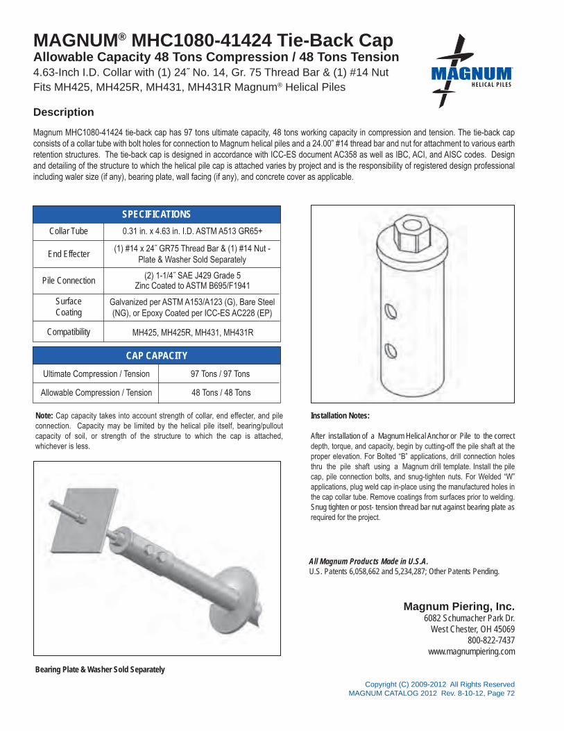
All Magnum Products Made in U.S.A.U.S. Patents 6,058,662 and 5,234,287; Other Patents Pending.
Magnum Piering, Inc.6082 Schumacher Park Dr.
West Chester, OH 45069800-822-7437
www.magnumpiering.com
Copyright (C) 2009-2012 All Rights ReservedMAGNUM CATALOG 2012 Rev. 8-10-12, Page 72
®
SPECIFICATIONS
CAP CAPACITY
MAGNUM® MHC1080-41424 Tie-Back Cap Allowable Capacity 48 Tons Compression / 48 Tons Tension 4.63-Inch I.D. Collar with (1) 24˝ No. 14, Gr. 75 Thread Bar & (1) #14 NutFits MH425, MH425R, MH431, MH431R Magnum® Helical Piles
Magnum MHC1080-41424 tie-back cap has 97 tons ultimate capacity, 48 tons working capacity in compression and tension. The tie-back cap consists of a collar tube with bolt holes for connection to Magnum helical piles and a 24.00” #14 thread bar and nut for attachment to various earth retention structures. The tie-back cap is designed in accordance with ICC-ES document AC358 as well as IBC, ACI, and AISC codes. Design and detailing of the structure to which the helical pile cap is attached varies by project and is the responsibility of registered design professional including waler size (if any), bearing plate, wall facing (if any), and concrete cover as applicable.
Collar Tube 0.31 in. x 4.63 in. I.D. ASTM A513 GR65+
End Effecter
Pile Connection (2) 1-1/4˝ SAE J429 Grade 5 Zinc Coated to ASTM B695/F1941
SurfaceCoating
Galvanized per ASTM A153/A123 (G), Bare Steel(NG), or Epoxy Coated per ICC-ES AC228 (EP)
Compatibility MH425, MH425R, MH431, MH431R
Ultimate Compression / Tension 97 Tons / 97 Tons
Allowable Compression / Tension 48 Tons / 48 Tons
(1) #14 x 24˝ GR75 Thread Bar & (1) #14 Nut - Plate & Washer Sold Separately
Installation Notes:
After installation of a Magnum Helical Anchor or Pile to the correct depth, torque, and capacity, begin by cutting-off the pile shaft at the proper elevation. For Bolted “B” applications, drill connection holes thru the pile shaft using a Magnum drill template. Install the pile cap, pile connection bolts, and snug-tighten nuts. For Welded “W” applications, plug weld cap in-place using the manufactured holes in the cap collar tube. Remove coatings from surfaces prior to welding. Snug tighten or post- tension thread bar nut against bearing plate as required for the project.
Note: Cap capacity takes into account strength of collar, end effecter, and pile connection. Capacity may be limited by the helical pile itself, bearing/pullout capacity of soil, or strength of the structure to which the cap is attached, whichever is less.
Bearing Plate & Washer Sold Separately
Description

All Magnum Products Made in U.S.A.U.S. Patents 6,058,662 and 5,234,287; Other Patents Pending.
Magnum Piering, Inc.6082 Schumacher Park Dr.
West Chester, OH 45069800-822-7437
www.magnumpiering.com
Copyright (C) 2009-2012 All Rights ReservedMAGNUM CATALOG 2012 Rev. 8-10-12, Page 73
®
SPECIFICATIONS
CAP CAPACITY
MAGNUM® MHC1080-52024B Tie-Back CapAllowable Capacity 98 Tons Compression* / 98 Tons Tension 5.62-Inch I.D. Collar with (1) 24˝ #20, Gr. 75 Thread Bar & #20 NutFits MH530B, and MH536B Magnum® Helical Piles
Magnum MHC1080-52024B tie-back cap has 196 tons ultimate capacity, 98 tons working capacity in compression* and tension. The tie-back cap consists of a collar tube with bolt holes for connection to Magnum helical piles and thread bar for attachment to various earth retention structures. The tie-back cap is designed in accordance with ICC-ES document AC358 as well as IBC, ACI, and AISC codes. Design and detailing of the structure to which the helical pile cap is attached varies by project and is the responsibility of registered design professional including waler size (if any), bearing plate, wall facing (if any), and concrete cover as applicable.
Installation Notes:
After installation of a Magnum Helical Anchor or Pile to the correct depth, torque, and capacity, begin by cutting-off the pile shaft at the proper elevation. For Bolted “B” applications, drill connection holes thru the pile shaft using a Magnum drill template. Install the pile cap, pile connection bolts, and snug-tighten nuts. For Welded “W” applications, plug weld cap in-place using the manufactured holes in the cap collar tube. Remove coatings from surfaces prior to welding. Snug tighten or post- tension thread bar nut against bearing plate as required for the project.
Collar Tube 0.38 in. x 5.62 in. I.D. ASTM A513 GR65+
End Effecter
Pile Connection (3) 1-1/2˝ SAE J429 Grade 5Zinc Coated to ASTM B695/F1941
SurfaceCoating
Galvanized per ASTM A153/A123 (G), Bare Steel(NG), or Epoxy Coated per ICC-ES AC228 (EP)
Compatibility MH530B and MH536B
Ultimate Compression / Tension 196 Tons / 196 Tons
Allowable Compression / Tension 98 Tons / 98 Tons
(1) #20 x 24˝ GR75 Thread Bar & #20 Nut -Plate & Washer Sold Separately
Description
Bearing Plate & Washer Sold Separately
*Compression application requires appropriate sized bearing plate be secured with double hex nut similar to a micropile connection.

All Magnum Products Made in U.S.A.U.S. Patents 6,058,662 and 5,234,287; Other Patents Pending.
Magnum Piering, Inc.6082 Schumacher Park Dr.
West Chester, OH 45069800-822-7437
www.magnumpiering.com
Copyright (C) 2009-2012 All Rights ReservedMAGNUM CATALOG 2012 Rev. 8-10-12, Page 74
®
SPECIFICATIONS
CAP CAPACITY
MAGNUM® MHC1080-62024 Tie-Back CapAllowable Capacity 95 Tons Compression / 95 Tons Tension 5.85-Inch I.D. Collar with (1) 24˝ #20, Gr. 75 Thread Bar & #20 NutFits MH625, MH625R, MH637, MH637R, MH646, MH646R Magnum® Helical Piles
Magnum MHC108-62024 tie-back cap has 191 tons ultimate capacity, 95 tons working capacity in compression and tension. The tie-back cap consists of a collar tube with bolt holes for connection to Magnum helical piles and thread bar for attachment to various earth retention structures. The tie-back cap is designed in accordance with ICC-ES document AC358 as well as IBC, ACI, and AISC codes. Design and detailing of the structure to which the helical pile cap is attached varies by project and is the responsibility of registered design professional including waler size (if any), bearing plate, wall facing (if any), and concrete cover as applicable.
Installation Notes:
After installation of a Magnum Helical Anchor or Pile to the correct depth, torque, and capacity, begin by cutting-off the pile shaft at the proper elevation. For Bolted “B” applications, drill connection holes thru the pile shaft using a Magnum drill template. Install the pile cap, pile connection bolts, and snug-tighten nuts. For Welded “W” applications, plug weld cap in-place using the manufactured holes in the cap collar tube. Remove coatings from surfaces prior to welding. Snug tighten or post- tension thread bar nut against bearing plate as required for the project.
Collar Tube 0.38 in. x 5.85 in. I.D. ASTM A513 GR65+
End Effecter
Pile Connection (3) 1-1/2˝ SAE J429 Grade 5Zinc Coated to ASTM B695/F1941
SurfaceCoating
Galvanized per ASTM A153/A123 (G), Bare Steel(NG), or Epoxy Coated per ICC-ES AC228 (EP)
Compatibility MH625, MH625R, MH637, MH637R, MH646, MH646R
Ultimate Compression / Tension 191 Tons / 191 Tons
Allowable Compression / Tension 95 Tons / 95 Tons
(1) #20 x 24˝ GR75 Thread Bar & #20 Nut - Plate & Washer Sold Separately
Bearing Plate & Washer Sold Separately
Description

All Magnum Products Made in U.S.A.U.S. Patents 6,058,662 and 5,234,287; Other Patents Pending.
Magnum Piering, Inc.6082 Schumacher Park Dr.
West Chester, OH 45069800-822-7437
www.magnumpiering.com
Copyright (C) 2009-2012 All Rights ReservedMAGNUM CATALOG 2012 Rev. 8-10-12, Page 75
®
SPECIFICATIONS
CAP CAPACITY
MAGNUM® MHC1100-316 Slab Lift CapAllowable Capacity - 14 Tons Compression 3.13-Inch I.D. Collar with 16˝ Channel and Lifting Bolt AssemblyFits MH313, MH313R, MH325, MH325R Magnum® Helical Piles
Magnum MHC1100-3 slab lift cap as 28 tons ultimate capacity, 14 tons working capacity in compression. The slab lift cap consists of a collar tube with bolt hole for connection to Magnum helical piles and a channel and lifting bolt for insertion under existing slabs. The slab lift cap is designed in accordance with ICC-ES document AC358 as well as IBC, ACI, and AISC codes. Spacing and placement of the lifting caps under the existing slab varies by project and is the responsibility of registered design professional including maximum span of slab.
Installation Notes:
Core a hole through the slab slightly larger than the largest helix. Excavate a void large enough to facilitate channel installation. Install a Magnum Helical Pile to the correct depth, torque, and capacity. Cut-off the pile shaft at the proper elevation. Place the pile cap over the shaft. Place the channel under the slab with lifting bolt in place. Tighten the lifting bolt to raise the slab elevation as needed. Fill the void under the slab and core hole with fast-setting, high-strength, non-shrink grout.
Direct Bearing on Pile ShaftZinc Coated to ASTM B695/F1941
Ultimate Compression 28 Tons
Allowable Compression 14 Tons
Collar Tube 0.25 in. x 3.13 in. I.D. ASTM A513 GR65+
End Effecter
Pile Connection
SurfaceCoating
Galvanized per ASTM A153/A123 (G), Bare Steel(NG), or Epoxy Coated per ICC-ES AC228 (EP)
Compatibility MH313, MH313R, MH325, and MH325R
6˝ x 3.5˝ x 3/8˝ – 16˝ Long Channel and a 1.13˝ Lifting Bolt
Description

All Magnum Products Made in U.S.A.U.S. Patents 6,058,662 and 5,234,287; Other Patents Pending.
Magnum Piering, Inc.6082 Schumacher Park Dr.
West Chester, OH 45069800-822-7437
www.magnumpiering.com
Copyright (C) 2009-2012 All Rights ReservedMAGNUM CATALOG 2012 Rev. 8-10-12, Page 76
®
SPECIFICATIONS
CAP CAPACITY
MAGNUM® MHC1100-336 Slab Lift CapAllowable Capacity - 14 Tons Compression 3.13-Inch I.D. Collar with 36˝ Channel and Lifting Bolt AssemblyFits MH313, MH313R, MH325, MH325R Magnum® Helical Piles
Magnum MHC1100-336 slab lift cap has 28 tons ultimate capacity, 14 tons working capacity in compression. The slab lift cap consists of a collar tube with bolt hole for connection to Magnum helical piles and a channel and lifting bolt for insertion under existing slabs. The slab lift cap is designed in accordance with ICC-ES document AC358 as well as IBC, ACI, and AISC codes. Spacing and placement of the lifting caps under the existing slab varies by project and is the responsibility of registered design professional including maximum span of slab.
Collar Tube 0.25 in. x 3.13 in. I.D. ASTM A513 GR65+
End Effecter
Pile ConnectionDirect Bearing on Pile Shaft
Zinc Coated to ASTM B695/F1941
SurfaceCoating
Galvanized per ASTM A153/A123 (G), Bare Steel(NG), or Epoxy Coated per ICC-ES AC228 (EP)
Compatibility MH313, MH313R, MH325, and MH325R
Ultimate Compression 28 Tons
Allowable Compression 14 Tons
6˝ x 3.5˝ x 3/8˝ – 36˝ Long Channel and a 1.13˝ Lifting Bolt
Installation Notes:
Core a hole through the slab slightly larger than the largest helix. Excavate a void large enough to facilitate channel installation. Install a Magnum Helical Pile to the correct depth, torque, and capacity. Cut-off the pile shaft at the proper elevation. Place the pile cap over the shaft. Place the channel under the slab with lifting bolt in place. Tighten the lifting bolt to raise the slab elevation as needed. Fill the void under the slab and core hole with fast-setting, high-strength, non-shrink grout.
Description

All Magnum Products Made in U.S.A.U.S. Patents 6,058,662 and 5,234,287; Other Patents Pending.
Magnum Piering, Inc.6082 Schumacher Park Dr.
West Chester, OH 45069800-822-7437
www.magnumpiering.com
Copyright (C) 2009-2012 All Rights ReservedMAGNUM CATALOG 2012 Rev. 8-10-12, Page 77
®
SPECIFICATIONS
CAP CAPACITY
MAGNUM® MHC1120-3 Wood Beam CapAllowable Capacity - 8 Tons Compression / 8 Tons Tension 3.13-Inch I.D. Collar with 11˝ Long 3.5˝ x 3.5˝ x 0.25˝ AngleFits MH313, MH313R, MH325 Magnum® Helical Piles
Magnum MHC1120-3 wood beam cap has 16 tons ultimate capacity, 8 tons working capacity in compression and tension. The wood beam cap consists of a collar tube with bolt hole for connection to Magnum helical piles and an angle for attachment to a wood beam. The wood beam cap is designed in accordance with ICC-ES document AC358 as well as IBC, ACI, and AISC codes. Application of the cap varies by project and is the responsibility of registered design professional including crushing strength and span of wood beam.
Installation Notes:
After installation of a Magnum Helical Pile to the correct depth, torque, and capacity, cut-off the pile shaft at the proper elevation. Drill .938˝ diameter hole through the shaft using a Magnum drill template. Place the pile cap over the shaft and secure with 0.88˝ bolt. Snug tighten nut. Place wood beam on cap angle and secure with 0.50˝ lag bolts as required for the project.
(1) 7/8˝ Diam. SAE J429 Grade 5Zinc Coated to ASTM B695/F1941
Ultimate Compression / Tension 16 Tons / 16 Tons
Allowable Compression / Tension 8 Tons / 8 Tons
Collar Tube 0.25 in. x 3.13 in. I.D. ASTM A513 GR65+
End Effecter
Pile Connection
SurfaceCoating
Galvanized per ASTM A153/A123 (G), Bare Steel(NG), or Epoxy Coated per ICC-ES AC228 (EP)
Compatibility MH313, MH313R, MH325
3.5˝ x 3.5˝ x 0.25˝ – 11˝ Long Angle with holes for (5) 1/2˝ Lag Bolts
Description
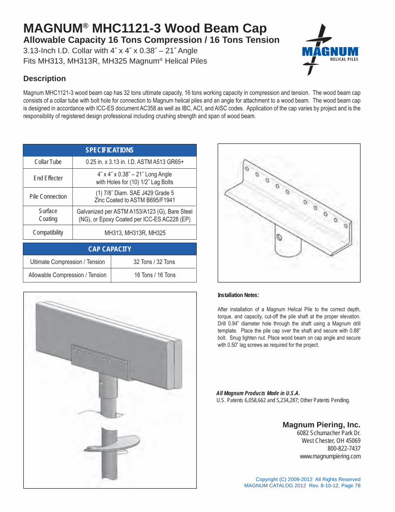
All Magnum Products Made in U.S.A.U.S. Patents 6,058,662 and 5,234,287; Other Patents Pending.
Magnum Piering, Inc.6082 Schumacher Park Dr.
West Chester, OH 45069800-822-7437
www.magnumpiering.com
Copyright (C) 2009-2012 All Rights ReservedMAGNUM CATALOG 2012 Rev. 8-10-12, Page 78
®
SPECIFICATIONS
CAP CAPACITY
MAGNUM® MHC1121-3 Wood Beam CapAllowable Capacity 16 Tons Compression / 16 Tons Tension 3.13-Inch I.D. Collar with 4˝ x 4˝ x 0.38˝ – 21˝ AngleFits MH313, MH313R, MH325 Magnum® Helical Piles
Magnum MHC1121-3 wood beam cap has 32 tons ultimate capacity, 16 tons working capacity in compression and tension. The wood beam cap consists of a collar tube with bolt hole for connection to Magnum helical piles and an angle for attachment to a wood beam. The wood beam cap is designed in accordance with ICC-ES document AC358 as well as IBC, ACI, and AISC codes. Application of the cap varies by project and is the responsibility of registered design professional including crushing strength and span of wood beam.
Collar Tube 0.25 in. x 3.13 in. I.D. ASTM A513 GR65+
End Effecter
Pile Connection (1) 7/8˝ Diam. SAE J429 Grade 5Zinc Coated to ASTM B695/F1941
SurfaceCoating
Galvanized per ASTM A153/A123 (G), Bare Steel(NG), or Epoxy Coated per ICC-ES AC228 (EP)
Compatibility MH313, MH313R, MH325
Ultimate Compression / Tension 32 Tons / 32 Tons
Allowable Compression / Tension 16 Tons / 16 Tons
4˝ x 4˝ x 0.38˝ – 21˝ Long Angle with Holes for (10) 1/2˝ Lag Bolts
Installation Notes:
After installation of a Magnum Helical Pile to the correct depth, torque, and capacity, cut-off the pile shaft at the proper elevation. Drill 0.94” diameter hole through the shaft using a Magnum drill template. Place the pile cap over the shaft and secure with 0.88” bolt. Snug tighten nut. Place wood beam on cap angle and secure with 0.50” lag screws as required for the project.
Description

All Magnum Products Made in U.S.A.U.S. Patents 6,058,662 and 5,234,287; Other Patents Pending.
Magnum Piering, Inc.6082 Schumacher Park Dr.
West Chester, OH 45069800-822-7437
www.magnumpiering.com
Copyright (C) 2009-2012 All Rights ReservedMAGNUM CATALOG 2012 Rev. 8-10-12, Page 79
®
SPECIFICATIONS
CAP CAPACITY
MAGNUM® MHC1122-3 Wood Beam CapAllowable Capacity 6 Tons Compression / 6 Tons Tension 3.13-Inch I.D. Collar with 8˝ x 4˝ x 0.13˝ – 8˝ Long AngleFits MH313, MH313R, MH325, MH325R Magnum® Helical Piles
Magnum MHC1122-3 wood beam cap has 12 tons ultimate capacity, 6 tons working capacity in compression and tension. The wood beam cap consists of a collar tube with bolt hole for connection to Magnum helical piles and an angle for attachment to a wood beam. This cap was designed to be used with the Magnum K-brace system for boardwalks but can be used with other wood structures. The wood beam cap is designed in accordance with ICC-ES document AC358 as well as IBC, ACI, and AISC codes. Application of the cap varies by project and is the responsibility of registered design professional including crushing strength, lateral bracing, and span of wood beam.
Installation Notes:
After installation of a Magnum Helical Pile to the correct depth, torque, and capacity, cut-off the pile shaft at the proper elevation. Place the pile cap over the shaft and secure with 4 Hilti EDS PAF. Place wood beam on cap angle and secure with ½˝ lag screws as required for the project. If required, install Magnum K-brace system in accordance with installation instructions for that product.
(4) Hilti EDS PAFZinc Coated to ASTM B695/F1941
Ultimate Compression / Tension 12 Tons / 12 Tons
Allowable Compression / Tension 6 Tons / 6 Tons
Collar Tube 0.25 in. x 3.13 in. I.D. ASTM A513 GR65+
End Effecter
Pile Connection
SurfaceCoating
Galvanized per ASTM A153/A123 (G), Bare Steel(NG), or Epoxy Coated per ICC-ES AC228 (EP)
Compatibility MH313, MH313R, MH325, and MH325R
8˝ x 4˝ x 0.13˝ – 8˝ Long Angle with holes for (4) 1/2˝ Lag Bolts
Description
K-Brace Assembly Sold Separately

All Magnum Products Made in U.S.A.U.S. Patents 6,058,662 and 5,234,287; Other Patents Pending.
Magnum Piering, Inc.6082 Schumacher Park Dr.
West Chester, OH 45069800-822-7437
www.magnumpiering.com
Copyright (C) 2009-2012 All Rights ReservedMAGNUM CATALOG 2012 Rev. 8-10-12, Page 80
®
SPECIFICATIONS
CAP CAPACITY
MAGNUM® MHC1123-3 Wood Beam CapAllowable Capacity 8 Tons Compression / 8 Tons Tension 3.13-Inch I.D. Collar with 8˝ x 3.75˝ x 0.13˝ – 6˝ Long AngleFits MH313, MH313R, MH325 Magnum® Helical Piles
Magnum MHC1123-3 wood beam cap has 16 tons ultimate capacity, 8 tons working capacity in compression and tension. The wood beam cap consists of a collar tube with bolt hole for connection to Magnum helical piles and an angle for attachment to a wood beam. The wood beam cap is designed in accordance with ICC-ES document AC358 as well as IBC, ACI, and AISC codes. Application of the cap varies by project and is the responsibility of registered design professional including crushing strength, lateral bracing, and span of wood beam.
Collar Tube 0.25 in. x 3.13 in. I.D. ASTM A513 GR65+
End Effecter
Pile Connection (1) 7/8˝ Diam. SAE J429 Grade 5Zinc Coated to ASTM B695/F1941
SurfaceCoating
Galvanized per ASTM A153/A123 (G), Bare Steel(NG), or Epoxy Coated per ICC-ES AC228 (EP)
Compatibility MH313, MH313R, MH325
Ultimate Compression / Tension 16 Tons / 16 Tons
Allowable Compression / Tension 8 Tons / 8 Tons
8˝ x 3.75˝ x 0.13˝ – 6˝ Long Angle with Holes for (3) 1/2˝ Lag Bolts
Installation Notes:
After installation of a Magnum Helical Pile to the correct depth, torque, and capacity, cut-off the pile shaft at the proper elevation. Drill 0.94˝ diameter hole through the shaft using a Magnum drill template. Place the pile cap over the shaft and secure with 0.88˝ bolt. Snug tighten nut. Place wood beam on cap angle and secure with 0.50˝ lag screws as required for the project.
Description

All Magnum Products Made in U.S.A.U.S. Patents 6,058,662 and 5,234,287; Other Patents Pending.
Magnum Piering, Inc.6082 Schumacher Park Dr.
West Chester, OH 45069800-822-7437
www.magnumpiering.com
Copyright (C) 2009-2012 All Rights ReservedMAGNUM CATALOG 2012 Rev. 8-10-12, Page 81
®
SPECIFICATIONS
CAP CAPACITY
MAGNUM® MHC1130-3 Wood Corner CapAllowable Capacity 8 Tons Compression / 8 Tons Tension 3.13-Inch I.D. Collar w/ (2) Intersecting 3.5˝ x 3.5˝ x 0.25˝ – 7.25˝ Long AnglesFits MH313, MH313R, MH325 Magnum® Helical Piles
Magnum MHC1130-3 wood corner cap has 16 tons ultimate capacity, 8 tons working capacity in compression and tension. The wood corner cap consists of a collar tube with bolt hole for connection to Magnum helical piles and two angles oriented at 90 deg for attachment to two intersecting wood beams. The wood corner cap is designed in accordance with ICC-ES document AC358 as well as IBC, ACI, and AISC codes. Application of the cap varies by project and is the responsibility of registered design professional including crushing strength, lateral bracing, and span of wood beams.
Installation Notes:
After installation of a Magnum Helical Pile to the correct depth, torque, and capacity, cut-off the pile shaft at the proper elevation. Drill 0.94˝ hole using Magnum drill template. Place the pile cap over the shaft and secure with 0.88” bolt. Snug tighten nut. Place wood beams on cap angle and secure with 0.50˝ lag screws as required for the project.
(1) 7/8˝ SAE J429 Grade 5Zinc Coated to ASTM B695/F1941
Ultimate Compression / Tension 16 Tons / 16 Tons
Allowable Compression / Tension 8 Tons / 8 Tons
Collar Tube 0.25 in. x 3.13 in. I.D. ASTM A513 GR65+
End Effecter
Pile Connection
SurfaceCoating
Galvanized per ASTM A153/A123 (G), Bare Steel(NG), or Epoxy Coated per ICC-ES AC228 (EP)
Compatibility MH313, MH313R, MH325
3.50˝ x 3.50˝ x 0.25˝ – 7.25˝ Long Angle at 90 deg with holes for (4) 1/2˝ Lag Bolts
Description

All Magnum Products Made in U.S.A.U.S. Patents 6,058,662 and 5,234,287; Other Patents Pending.
Magnum Piering, Inc.6082 Schumacher Park Dr.
West Chester, OH 45069800-822-7437
www.magnumpiering.com
Copyright (C) 2009-2012 All Rights ReservedMAGNUM CATALOG 2012 Rev. 8-10-12, Page 82
®
SPECIFICATIONS
CAP CAPACITY
MAGNUM® MHC1130-35 Wood Corner CapAllowable Capacity 8 Tons Compression / 8 Tons Tension 3.63-Inch I.D. Collar w/ (2) Intersecting L3.5˝ x 3.5˝ x 1/4” – 7.25˝ Long AnglesFits MH3521 and MH3521R Magnum® Helical Piles
Magnum MHC1130-35 wood corner cap has 16 tons ultimate capacity, 8 tons working capacity in compression and tension. The wood corner cap consists of a collar tube with bolt hole for connection to Magnum helical piles and two angles oriented at 90 deg for attachment to two intersecting wood beams. The wood corner cap is designed in accordance with ICC-ES document AC358 as well as IBC, ACI, and AISC codes. Application of the cap varies by project and is the responsibility of registered design professional including crushing strength, lateral bracing, and span of wood beams.
Collar Tube 0.25 in. x 3.63 in. I.D. ASTM A513 GR65+
End Effecter
Pile Connection (1) 1˝ SAE J429 Grade 8Zinc Coated to ASTM B695/F1941
SurfaceCoating
Galvanized per ASTM A153/A123 (G), Bare Steel(NG), or Epoxy Coated per ICC-ES AC228 (EP)
Compatibility MH3521 and MH3521R
Ultimate Compression / Tension 16 Tons / 16 Tons
Allowable Compression / Tension 8 Tons / 8 Tons
3.5˝ x 3.5˝ x 1/4˝ – 7.25˝ Long Angles at 90 deg with holes for (4) 1/2˝ Lag Bolts
Installation Notes:
After installation of a Magnum Helical Pile to the correct depth, torque, and capacity, cut-off the pile shaft at the proper elevation. Drill 17/16˝ holes using Magnum drill template. Place the pile cap over the shaft and secure with 1˝ bolt. Snug tighten nut. Place wood beams on cap angle and secure with 1/2˝ lag screws as required for the project.
Description

All Magnum Products Made in U.S.A.U.S. Patents 6,058,662 and 5,234,287; Other Patents Pending.
Magnum Piering, Inc.6082 Schumacher Park Dr.
West Chester, OH 45069800-822-7437
www.magnumpiering.com
Copyright (C) 2009-2012 All Rights ReservedMAGNUM CATALOG 2012 Rev. 8-10-12, Page 83
®
SPECIFICATIONS
CAP CAPACITY
MAGNUM® MHC1160-3 4x4 Post CapAllowable Capacity 8 Tons Compression / 8 Tons Tension 3.13-Inch I.D. Collar with 2˝ Tall 3.625˝ x 3.625˝ x 0.188˝ Post BaseFits MH313, MH313R, MH325 Magnum® Helical Piles
Magnum MHC1160-3 4x4 post cap has 17 tons ultimate capacity, 8 tons working capacity in compression and tension. The 4x4 post cap consists of a collar tube with bolt hole for connection to Magnum helical piles and 3.625˝ x 3.625˝ post base for attachment to a 4.00˝ x 4.00˝ dimensioned wood post. The 4x4 post cap is designed in accordance with ICC-ES document AC358 as well as IBC, ACI, and AISC codes. Application of the cap varies by project and is the responsibility of registered design professional including crushing strength, lateral bracing, and buckling of wood post.
Installation Notes:
After installation of a Magnum Helical Pile to the correct depth, torque, and capacity, cut-off the pile shaft at the proper elevation. Drill .94˝ hole using Magnum drill template. Place the pile cap over the shaft and secure with 7/8˝ bolt. Snug tighten nut. Place wood post on post base and secure with 1/4˝ lag screws as required for the project.
(1) 7/8˝ SAE J429 Grade 5Zinc Coated to ASTM B695/F1941
Ultimate Compression / Tension 17 Tons / 17 Tons
Allowable Compression / Tension 8 Tons / 8 Tons
Collar Tube 0.25 in. x 3.13 in. I.D. ASTM A513 GR65+
End Effecter
Pile Connection
SurfaceCoating
Galvanized per ASTM A153/A123 (G), Bare Steel(NG), or Epoxy Coated per ICC-ES AC228 (EP)
Compatibility MH313, MH313R, MH325
2˝ tall 3.625˝ x 3.625˝ x 0.188˝ Post Base with Holes for (6) 1/4˝ Lag Bolts
Description

All Magnum Products Made in U.S.A.U.S. Patents 6,058,662 and 5,234,287; Other Patents Pending.
Magnum Piering, Inc.6082 Schumacher Park Dr.
West Chester, OH 45069800-822-7437
www.magnumpiering.com
Copyright (C) 2009-2012 All Rights ReservedMAGNUM CATALOG 2012 Rev. 8-10-12, Page 84
®
SPECIFICATIONS
CAP CAPACITY
MAGNUM® MHC1160-35 4x4 Post CapAllowable Capacity 8 Tons Compression / 8 Tons Tension3.63-Inch I.D. Collar with 2˝ Tall 3.625˝ x 3.625˝ x 0.188˝ Post BaseFits MH3521 and MH3521R Magnum® Helical Piles
Magnum MHC1160-3R 4x4 post cap has 17 tons ultimate capacity, 8 tons working capacity in compression and tension. The 4x4 post cap consists of a collar tube with bolt hole for connection to Magnum helical piles and 3.625˝ x 3.625˝ post base for attachment to a 4x4 dimensioned wood post. The 4x4 post cap is designed in accordance with ICC-ES document AC358 as well as IBC, ACI, and AISC codes. Application of the cap varies by project and is the responsibility of registered design professional including crushing strength, lateral bracing, and buckling of wood post.
Collar Tube 0.25 in. x 3.63 in. I.D. ASTM A513 GR65+
End Effecter
Pile Connection (1) 1˝ SAE J429 Grade 8Zinc Coated to ASTM B695/F1941
SurfaceCoating
Galvanized per ASTM A153/A123 (G), Bare Steel(NG), or Epoxy Coated per ICC-ES AC228 (EP)
Compatibility MH3521 and MH3521R
Ultimate Compression / Tension 17 Tons / 17 Tons
Allowable Compression / Tension 8 Tons / 8 Tons
2˝ tall 3.625˝ x 3.625˝ x 0.188˝ Post Base with Holes for (6) 1/4˝ Lag Bolts
Installation Notes:
After installation of a Magnum Helical Pile to the correct depth, torque, and capacity, cut-off the pile shaft at the proper elevation. Drill 17/16˝ hole using Magnum drill template. Place the pile cap over the shaft and secure with 1˝ bolt. Snug tighten nut. Place wood post on post base and secure with 1/4˝ lag screws as required for the project.
Description

All Magnum Products Made in U.S.A.U.S. Patents 6,058,662 and 5,234,287; Other Patents Pending.
Magnum Piering, Inc.6082 Schumacher Park Dr.
West Chester, OH 45069800-822-7437
www.magnumpiering.com
Copyright (C) 2009-2012 All Rights ReservedMAGNUM CATALOG 2012 Rev. 8-10-12, Page 85
®
SPECIFICATIONS
CAP CAPACITY
MAGNUM® MHC1161-3 6x6 Post CapAllowable Capacity 16 Tons Compression / 16 Tons Tension 3.13-Inch I.D. Collar with 3˝ Tall 5.625˝ x 5.625˝ x 0.25˝ Post BaseFits MH313, MH313R, MH325 Magnum® Helical Piles
Magnum MHC1161-3 6x6 post cap has 32 tons ultimate capacity, 16 tons working capacity in compression and tension. The 6x6 post cap consists of a collar tube with bolt hole for connection to Magnum helical piles and 5.625˝ x 5.625˝ post base for attachment to a 6x6 dimensioned wood post. The 6x6 post cap is designed in accordance with ICC-ES document AC358 as well as IBC, ACI, and AISC codes. Application of the cap varies by project and is the responsibility of registered design professional including crushing strength, lateral bracing, and buckling of wood post.
Installation Notes:
After installation of a Magnum Helical Pile to the correct depth, torque, and capacity, cut-off the pile shaft at the proper elevation. Drill 0.94˝ hole using Magnum drill template. Place the pile cap over the shaft and secure with 7/8˝ bolt. Snug tighten nut. Place wood post on post base and secure with 1/2˝ lag screws as required for the project.
(1) 7/8˝ SAE J429 Grade 5 Zinc Coated to ASTM B695/F1941
Ultimate Compression / Tension 32 Tons / 32 Tons
Allowable Compression / Tension 16 Tons / 16 Tons
Collar Tube 0.25 in. x 3.13 in. I.D. ASTM A513 GR65+
End Effecter
Pile Connection
SurfaceCoating
Galvanized per ASTM A153/A123 (G), Bare Steel(NG), or Epoxy Coated per ICC-ES AC228 (EP)
Compatibility MH313, MH313R, MH325
3˝ tall 5.625˝ x 5.625˝ x 0.25˝ Post Base with Holes for (6) 1/2˝ Lag Bolts
Description

All Magnum Products Made in U.S.A.U.S. Patents 6,058,662 and 5,234,287; Other Patents Pending.
Magnum Piering, Inc.6082 Schumacher Park Dr.
West Chester, OH 45069800-822-7437
www.magnumpiering.com
Copyright (C) 2009-2012 All Rights ReservedMAGNUM CATALOG 2012 Rev. 8-10-12, Page 86
®
SPECIFICATIONS
CAP CAPACITY
MAGNUM® MHC1206-3 ID Plate CapAllowable Capacity 16 Tons Compression / 16 Tons Tension2.5-Inch O.D. Collar with 6˝ x 6˝ x 0.375˝ Plate w/ 1/2˝ Threaded HoleFits MH313, MH313R, MH325 Magnum® Helical Piles
Magnum MHC1206-3 ID plate cap has 32 tons ultimate capacity, 16 tons working capacity in compression and tension. The ID plate cap consists of a collar tube with bolt hole for connection to Magnum helical piles and 6˝ x 6˝ x 0.375˝ plate with 1/2˝ hole for attachment to various wood and steel beams and posts. The ID plate cap is designed in accordance with ICC-ES document AC358 as well as IBC, ACI, and AISC codes. Application of the cap varies by project and is the responsibility of registered design professional including beam bearing, beam span, beam attachment, post attachment, and buckling of post.
Collar Tube 0.25 in. x 2.5 in. O.D. ASTM A513 GR65+
End Effecter
Pile Connection (1) 7/8˝ SAE J429 Grade 5 Zinc Coated to ASTM B695/F1941
SurfaceCoating
Galvanized per ASTM A153/A123 (G), Bare Steel(NG), or Epoxy Coated per ICC-ES AC228 (EP)
Compatibility MH313, MH313R, MH325
Ultimate Compression / Tension 32 Tons / 32 Tons
Allowable Compression / Tension 16 Tons / 16 Tons
6˝ x 6˝ x 0.375˝ Steel Plate with 1/2˝ Threaded Hole
Installation Notes:
After installation of a Magnum Helical Pile to the correct depth, torque, and capacity, cut-off the pile shaft at the proper elevation. Drill 0.94˝ hole using Magnum drill template. Place the pile cap inside the shaft and secure with 7/8˝ bolt. Snug tighten nut. Place wood or steel beam/post on cap and secure as required for the project.
Description

All Magnum Products Made in U.S.A.U.S. Patents 6,058,662 and 5,234,287; Other Patents Pending.
Magnum Piering, Inc.6082 Schumacher Park Dr.
West Chester, OH 45069800-822-7437
www.magnumpiering.com
Copyright (C) 2009-2012 All Rights ReservedMAGNUM CATALOG 2012 Rev. 8-10-12, Page 87
®
SPECIFICATIONS
CAP CAPACITY
MAGNUM® MHC1207-3 OD Plate CapAllowable Capacity 16 Tons Compression / 16 Tons Tension 3.13-Inch I.D. Collar with 6˝ x 6˝ x 0.375˝ Plate w/ 1/2˝ Threaded HoleFits MH313, MH313R, MH325 Magnum® Helical Piles
Magnum MHC1207-3 OD plate cap has 32 tons ultimate capacity, 16 tons working capacity in compression and tension. The OD plate cap consists of a collar tube with bolt hole for connection to Magnum helical piles and 6˝ x 6˝ x 0.38˝ plate with 1/2˝ hole for attachment to various wood and steel beams and posts. The OD plate cap is designed in accordance with ICC-ES document AC358 as well as IBC, ACI, and AISC codes. Application of the cap varies by project and is the responsibility of registered design professional including beam bearing, beam span, beam attachment, post attachment, and buckling of post.
Installation Notes:
After installation of a Magnum Helical Pile to the correct depth, orque, and capacity, cut-off the pile shaft at the proper elevation. Drill 0.94˝ hole using Magnum drill template. Place the pile cap over the shaft and secure with 7/8˝ bolt. Snug tighten nut. Place wood or steel beam/post on cap and secure as required for the project.
(1) 7/8˝ SAE J429 Grade 5Zinc Coated to ASTM B695/F1941
Ultimate Compression / Tension 32 Tons / 32 Tons
Allowable Compression / Tension 16 Tons / 16 Tons
Collar Tube 0.25 in. x 3.13 in. I.D. ASTM A513 GR65+
End Effecter
Pile Connection
SurfaceCoating
Galvanized per ASTM A153/A123 (G), Bare Steel(NG), or Epoxy Coated per ICC-ES AC228 (EP)
Compatibility MH313, MH313R, MH325
6˝ x 6˝ x 0.38˝ Steel Plate with 1/2” Threaded Hole
Description

All Magnum Products Made in U.S.A.U.S. Patents 6,058,662 and 5,234,287; Other Patents Pending.
Magnum Piering, Inc.6082 Schumacher Park Dr.
West Chester, OH 45069800-822-7437
www.magnumpiering.com
Copyright (C) 2009-2012 All Rights ReservedMAGNUM CATALOG 2012 Rev. 8-10-12, Page 88
®
SPECIFICATIONS
CAP CAPACITY
MAGNUM® MSC1300-150L55B Bearing Plate CapAllowable Capacity 17.5 Tons Compression / 12.5 Tons Tension 1.6-Inch Square Socket with 5˝ x 5˝ x 1/2˝ Bearing PlateFits MS150B Magnum® Helical Piles
The Magnum MSC1300-150L55B bearing plate cap has 35 tons ultimate capacity, 17.5 tons working capacity in compression and 25 tons ultimate capacity, 12.5 tons working capacity in tension. The bearing plate cap consists of a square socket tube with bolt hole for connection to Magnum helical piles and 5˝ x 5˝ x 1/2˝ plate for embedment in cast-in-place reinforced concrete. The bearing plate cap is designed in accordance with ICC-ES document AC358 as well as IBC, ACI, and AISC codes. Application of the cap varies by project and is the responsibility of registered design professional including minimum embedment for two-way and one-way punching shear, reinforcement of concrete, and pile spacing.
Installation Notes:
After installation of a Magnum Helical Pile to the correct depth, torque, and capacity, cut-off the pile shaft at the proper elevation. Drill 15/16˝ hole using Magnum drill template. Place the pile cap over the shaft and secure with 7/8˝ bolt. Ensure direct bearing of cap on shaft. Snug tighten nut. Place reinforcing steel as required for the project and cast concrete over and around the pile cap. Cap capacity is based on embedment in concrete pile cap at least 4x larger than plate size and minimum 2,500 psi concrete.
(1) 7/8˝ SAE J429 Grade 5Zinc Coated to ASTM B695/F1941
Ultimate Compression / Tension 35 Tons / 25 Tons
Allowable Compression / Tension 17.5 Tons / 12.5 Tons
Collar Tube 0.31˝ x 2.25˝ x 2.25˝ Sqr. ASTM A513 GR-65+
End Effecter
Pile Connection
SurfaceCoating
Galvanized per ASTM A153/A123 (G), Bare Steel(NG), or Epoxy Coated per ICC-ES AC228 (EP)
Compatibility MS150B
5˝ x 5˝ x 0.25˝ Steel Bearing Plate
Description
Note: Cap capacity takes into account strength of collar, end effecter, and pile connection. Capacity may be limited by the helical pile itself, bearing/pullout capacity of soil, or strength of the structure to which the cap is attached, whichever is less.

All Magnum Products Made in U.S.A.U.S. Patents 6,058,662 and 5,234,287; Other Patents Pending.
Magnum Piering, Inc.6082 Schumacher Park Dr.
West Chester, OH 45069800-822-7437
www.magnumpiering.com
Copyright (C) 2009-2012 All Rights ReservedMAGNUM CATALOG 2012 Rev. 8-10-12, Page 89
®
SPECIFICATIONS
CAP CAPACITY
MAGNUM® MSC1300-175M6565B Bearing Plate CapAllowable Capacity 27.5 Tons Compression / 20 Tons Tension1.9-Inch Square Socket with 6.5˝ x 6.5˝ x 5/8˝ Bearing PlateFits MS175B Magnum® Helical Piles
The Magnum MHC1300-175M6565S bearing plate cap has 55 tons ultimate capacity, 27.5 tons working capacity in compression and 40 tons ultimate capacity, 20 tons working capacity in tension. The bearing plate cap consists of a square socket tube with bolt hole for connection to Magnum helical piles and 6.5” x 6.5” x 5/8” plate for embedment in cast-in-place reinforced concrete. The bearing plate cap is designed in accordance with ICC-ES document AC358 as well as IBC, ACI, and AISC codes. Application of the cap varies by project and is the responsibility of registered design professional including minimum embedment for two-way and one-way punching shear, reinforcement of concrete, and pile spacing.
Collar Tube 0.31˝ x 2.5˝ x 2.5˝ Sqr. ASTM A513 GR-65+
End Effecter
Pile Connection (1) 1˝ SAE J429 Grade 8 Zinc Coated to ASTM B695/F1941
SurfaceCoating
Galvanized per ASTM A153/A123 (G), Bare Steel(NG), or Epoxy Coated per ICC-ES AC228 (EP)
Compatibility MS175B
Ultimate Compression / Tension 55 Tons / 40 Tons
Allowable Compression / Tension 27.5 Tons / 20 Tons
5˝ x 5˝ x 0.25˝ Steel Bearing Plate
Installation Notes:
After installation of a Magnum Helical Pile to the correct depth, torque, and capacity, cut-off the pile shaft at the proper elevation. Drill 17/16˝ hole using Magnum drill template. Place the pile cap over the shaft and secure with 1˝ bolt. Ensure direct bearing of cap on shaft. Snug tighten nut. Place reinforcing steel as required for the project and cast concrete over and around the pile cap. Cap capacity is based on embedment in concrete pile cap at least 4x larger than plate size and minimum 2,500 psi concrete.
Note: Cap capacity takes into account strength of collar, end effecter, and pile connection. Capacity may be limited by the helical pile itself, bearing/pullout capacity of soil, or strength of the structure to which the cap is attached, whichever is less.
Description
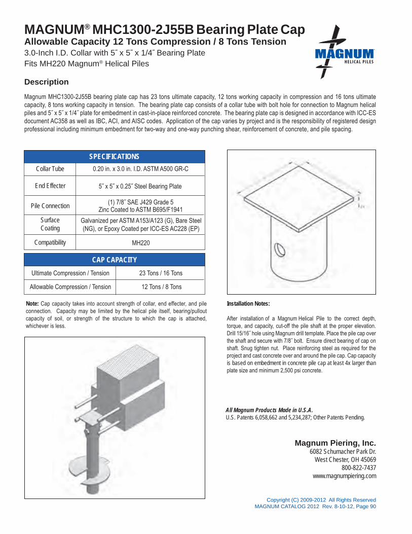
All Magnum Products Made in U.S.A.U.S. Patents 6,058,662 and 5,234,287; Other Patents Pending.
Magnum Piering, Inc.6082 Schumacher Park Dr.
West Chester, OH 45069800-822-7437
www.magnumpiering.com
Copyright (C) 2009-2012 All Rights ReservedMAGNUM CATALOG 2012 Rev. 8-10-12, Page 90
®
SPECIFICATIONS
CAP CAPACITY
MAGNUM® MHC1300-2J55B Bearing Plate CapAllowable Capacity 12 Tons Compression / 8 Tons Tension3.0-Inch I.D. Collar with 5˝ x 5˝ x 1/4˝ Bearing PlateFits MH220 Magnum® Helical Piles
Magnum MHC1300-2J55B bearing plate cap has 23 tons ultimate capacity, 12 tons working capacity in compression and 16 tons ultimate capacity, 8 tons working capacity in tension. The bearing plate cap consists of a collar tube with bolt hole for connection to Magnum helical piles and 5˝ x 5˝ x 1/4˝ plate for embedment in cast-in-place reinforced concrete. The bearing plate cap is designed in accordance with ICC-ES document AC358 as well as IBC, ACI, and AISC codes. Application of the cap varies by project and is the responsibility of registered design professional including minimum embedment for two-way and one-way punching shear, reinforcement of concrete, and pile spacing.
Collar Tube 0.20 in. x 3.0 in. I.D. ASTM A500 GR-C
End Effecter
Pile Connection (1) 7/8˝ SAE J429 Grade 5Zinc Coated to ASTM B695/F1941
SurfaceCoating
Galvanized per ASTM A153/A123 (G), Bare Steel(NG), or Epoxy Coated per ICC-ES AC228 (EP)
Compatibility MH220
Ultimate Compression / Tension 23 Tons / 16 Tons
Allowable Compression / Tension 12 Tons / 8 Tons
5˝ x 5˝ x 0.25˝ Steel Bearing Plate
Installation Notes:
After installation of a Magnum Helical Pile to the correct depth, torque, and capacity, cut-off the pile shaft at the proper elevation. Drill 15/16˝ hole using Magnum drill template. Place the pile cap over the shaft and secure with 7/8˝ bolt. Ensure direct bearing of cap on shaft. Snug tighten nut. Place reinforcing steel as required for the project and cast concrete over and around the pile cap. Cap capacity is based on embedment in concrete pile cap at least 4x larger than plate size and minimum 2,500 psi concrete.
Note: Cap capacity takes into account strength of collar, end effecter, and pile connection. Capacity may be limited by the helical pile itself, bearing/pullout capacity of soil, or strength of the structure to which the cap is attached, whichever is less.
Description

All Magnum Products Made in U.S.A.U.S. Patents 6,058,662 and 5,234,287; Other Patents Pending.
Magnum Piering, Inc.6082 Schumacher Park Dr.
West Chester, OH 45069800-822-7437
www.magnumpiering.com
Copyright (C) 2009-2012 All Rights ReservedMAGNUM CATALOG 2012 Rev. 8-10-12, Page 91
®
SPECIFICATIONS
CAP CAPACITY
MAGNUM® MHC1300-3J55B Bearing Plate CapAllowable Capacity 17 Tons Compression / 12 Tons Tension 3.13-Inch I.D. Collar with 5˝ x 5˝ x 0.25˝ Bearing PlateFits MH313, MH313R, MH325 Magnum® Helical Piles
Magnum MHC1300-3J55B bearing plate cap has 35 tons ultimate capacity, 17 tons working capacity in compression and 25 tons ultimate capacity, 12 tons working capacity in tension. The bearing plate cap consists of a collar tube with bolt hole for connection to Magnum helical piles and 5˝ x 5˝ x 1/4˝ plate for embedment in cast-in-place reinforced concrete. The bearing plate cap is designed in accordance with ICC-ES document AC358 as well as IBC, ACI, and AISC codes. Application of the cap varies by project and is the responsibility of registered design professional including minimum embedment for two-way and one-way punching shear, reinforcement of concrete, and pile spacing.
Installation Notes:
After installation of a Magnum Helical Pile to the correct depth, torque, and capacity, cut-off the pile shaft at the proper elevation Drill 15/16˝ hole using Magnum drill template. Place the pile cap over the shaft and secure with 7/8˝ bolt. Ensure direct bearing of plate on shaft. Snug tighten nut. Place reinforcing steel as required for the project and cast concrete over and around the pile cap. Cap capacity is based on embedment in concrete pile cap at least 4x larger than plate size and minimum 2,500 psi concrete.
(1) 7/8˝ SAE J429 Grade 5Zinc Coated to ASTM B695/F1941
Ultimate Compression / Tension 35 Tons / 25 Tons
Allowable Compression / Tension 17 Tons / 12 Tons
Collar Tube 0.25 in. x 3.13 in. I.D. ASTM A513 GR65+
End Effecter
Pile Connection
SurfaceCoating
Galvanized per ASTM A153/A123 (G), Bare Steel(NG), or Epoxy Coated per ICC-ES AC228 (EP)
Compatibility MH313, MH313R, MH325
5˝ x 5˝ x 0.25˝ Steel Bearing Plate
Note: Cap capacity takes into account strength of collar, end effecter, and pile connection. Capacity may be limited by the helical pile itself, bearing/pullout capacity of soil, or strength of the structure to which the cap is attached, whichever is less.
Description
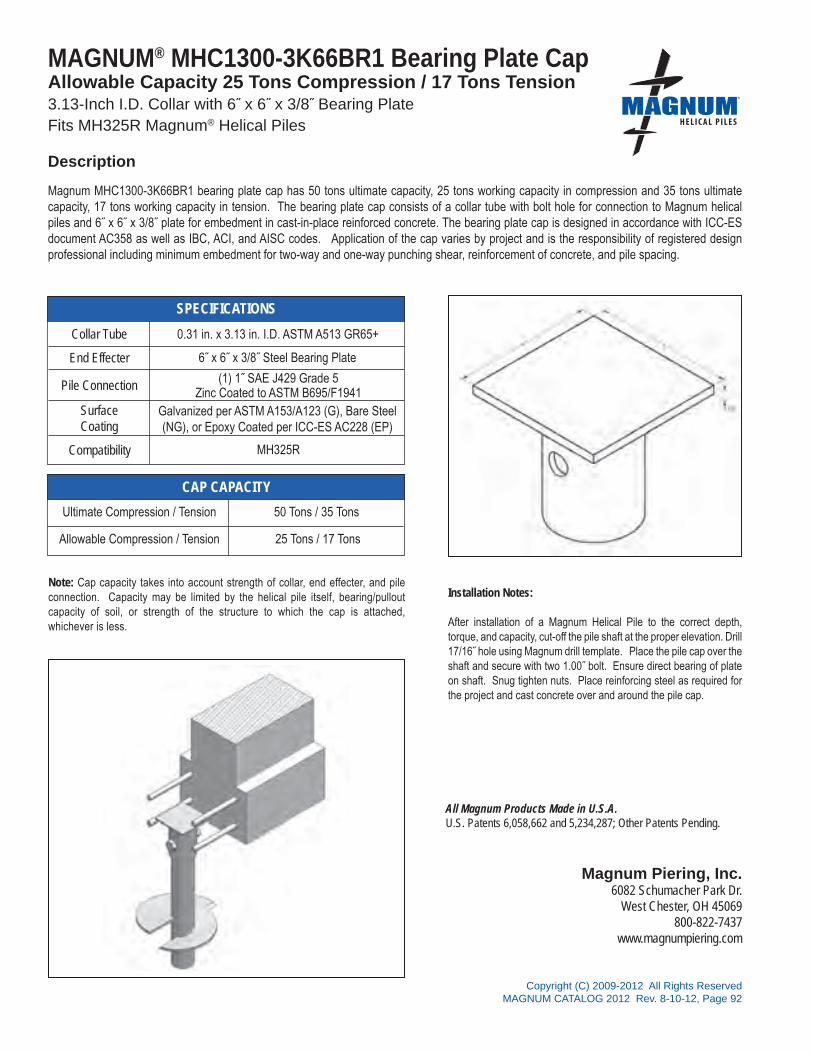
All Magnum Products Made in U.S.A.U.S. Patents 6,058,662 and 5,234,287; Other Patents Pending.
Magnum Piering, Inc.6082 Schumacher Park Dr.
West Chester, OH 45069800-822-7437
www.magnumpiering.com
Copyright (C) 2009-2012 All Rights ReservedMAGNUM CATALOG 2012 Rev. 8-10-12, Page 92
®
SPECIFICATIONS
CAP CAPACITY
MAGNUM® MHC1300-3K66BR1 Bearing Plate CapAllowable Capacity 25 Tons Compression / 17 Tons Tension3.13-Inch I.D. Collar with 6˝ x 6˝ x 3/8˝ Bearing PlateFits MH325R Magnum® Helical Piles
Magnum MHC1300-3K66BR1 bearing plate cap has 50 tons ultimate capacity, 25 tons working capacity in compression and 35 tons ultimate capacity, 17 tons working capacity in tension. The bearing plate cap consists of a collar tube with bolt hole for connection to Magnum helical piles and 6˝ x 6˝ x 3/8˝ plate for embedment in cast-in-place reinforced concrete. The bearing plate cap is designed in accordance with ICC-ES document AC358 as well as IBC, ACI, and AISC codes. Application of the cap varies by project and is the responsibility of registered design professional including minimum embedment for two-way and one-way punching shear, reinforcement of concrete, and pile spacing.
Installation Notes:
After installation of a Magnum Helical Pile to the correct depth, torque, and capacity, cut-off the pile shaft at the proper elevation. Drill 17/16˝ hole using Magnum drill template. Place the pile cap over the shaft and secure with two 1.00˝ bolt. Ensure direct bearing of plate on shaft. Snug tighten nuts. Place reinforcing steel as required for the project and cast concrete over and around the pile cap.
Note: Cap capacity takes into account strength of collar, end effecter, and pile connection. Capacity may be limited by the helical pile itself, bearing/pullout capacity of soil, or strength of the structure to which the cap is attached, whichever is less.
(1) 1˝ SAE J429 Grade 5Zinc Coated to ASTM B695/F1941
Ultimate Compression / Tension 50 Tons / 35 Tons
Allowable Compression / Tension 25 Tons / 17 Tons
Collar Tube 0.31 in. x 3.13 in. I.D. ASTM A513 GR65+
End Effecter
Pile Connection
SurfaceCoating
Galvanized per ASTM A153/A123 (G), Bare Steel(NG), or Epoxy Coated per ICC-ES AC228 (EP)
Compatibility MH325R
6˝ x 6˝ x 3/8˝ Steel Bearing Plate
Description

All Magnum Products Made in U.S.A.U.S. Patents 6,058,662 and 5,234,287; Other Patents Pending.
Magnum Piering, Inc.6082 Schumacher Park Dr.
West Chester, OH 45069800-822-7437
www.magnumpiering.com
Copyright (C) 2009-2012 All Rights ReservedMAGNUM CATALOG 2012 Rev. 8-10-12, Page 93
®
SPECIFICATIONS
CAP CAPACITY
MAGNUM® MHC1300-3L6565BR2 Bearing Plate Cap Allowable Capacity 25 Tons Compression / 25 Tons Tension 3.13-Inch I.D. Collar with 6.5˝ x 6.5˝ x 1/2˝ Bearing PlateFits MH325R Magnum® Helical Piles
Magnum MHC1300-3L6565BR2 bearing plate cap has 50 tons ultimate capacity, 25 tons working capacity in compression and 50 tons ultimate capacity, 25 tons working capacity in tension. The bearing plate cap consists of a collar tube with bolt hole for connection to Magnum helical piles and 6.50˝ x 6.50˝ x 0.50˝ plate for embedment in cast-in-place reinforced concrete. The bearing plate cap is designed in accordance with ICC-ES document AC358 as well as IBC, ACI, and AISC codes. Application of the cap varies by project and is the responsibility of registered design professional including minimum embedment for two-way and one-way punching shear, reinforcement of concrete, and pile spacing.
Installation Notes:
After installation of a Magnum Helical Pile to the correct depth, torque, and capacity, cut-off the pile shaft at the proper elevation. Drill 17/16˝ holes using Magnum drill template. Place the pile cap over the shaft and secure with two 1˝ bolts. Snug tighten nuts. Place reinforcing steel as required for the project and cast concrete over and around the pile cap. Cap capacity is based on embedment in concrete pile cap at least 4x larger than plate size and minimum 2,500 psi concrete.
(2) 1˝ SAE J429 Grade 5Zinc Coated to ASTM B695/F1941
Ultimate Compression / Tension 50 Tons
Allowable Compression / Tension 25 Tons
Collar Tube 0.31 in. x 3.13 in. I.D. ASTM A513 GR65+
End Effecter
Pile Connection
SurfaceCoating
Galvanized per ASTM A153/A123 (G), Bare Steel(NG), or Epoxy Coated per ICC-ES AC228 (EP)
Compatibility MH325R
6.5˝ x 6.5˝ x 1/2˝ Steel Bearing Plate
Note: Cap capacity takes into account strength of collar, end effecter, and pile connection. Capacity may be limited by the helical pile itself, bearing/pullout capacity of soil, or strength of the structure to which the cap is attached, whichever is less.
Description

All Magnum Products Made in U.S.A.U.S. Patents 6,058,662 and 5,234,287; Other Patents Pending.
Magnum Piering, Inc.6082 Schumacher Park Dr.
West Chester, OH 45069800-822-7437
www.magnumpiering.com
Copyright (C) 2009-2012 All Rights ReservedMAGNUM CATALOG 2012 Rev. 8-10-12, Page 94
®
SPECIFICATIONS
CAP CAPACITY
MAGNUM® MHC1300-35K66BR Bearing Plate CapAllowable Capacity 25 Tons Compression / 17 Tons Tension3.63-Inch I.D. Collar with 6˝ x 6˝ x 3/8˝ Bearing PlateFits MH3521B and MH3521BR Magnum® Helical Piles
Magnum MHC1300-35K66BR bearing plate cap has 50 tons ultimate capacity, 25 tons working capacity in compression and 35 tons ultimate capacity, 17 tons working capacity in tension. The bearing plate cap consists of a collar tube with bolt hole for connection to Magnum helical piles and 6˝ x 6˝ x 3/8˝ plate for embedment in cast-in-place reinforced concrete. The bearing plate cap is designed in accordance with ICC-ES document AC358 as well as IBC, ACI, and AISC codes. Application of the cap varies by project and is the responsibility of registered design professional including minimum embedment for two-way and one-way punching shear, reinforcement of concrete, and pile spacing.
Installation Notes:
After installation of a Magnum Helical Pile to the correct depth, torque, and capacity, cut-off the pile shaft at the proper elevation Drill 17/16˝ hole using Magnum drill template. Place the pile cap over the shaft and secure with 1.00˝ bolt. Ensure direct bearing of plate on shaft. Snug tighten nuts. Place reinforcing steel as required for the project and cast concrete over and around the pile cap. Cap capacity is based on embedment in concrete pile cap at least 4x larger than plate size and minimum 2,500 psi concrete.
Note: Cap capacity takes into account strength of collar, end effecter, and pile connection. Capacity may be limited by the helical pile itself, bearing/pullout capacity of soil, or strength of the structure to which the cap is attached, whichever is less.
(1) 1˝ SAE J429 Grade 8Zinc Coated to ASTM B695/F1941
Ultimate Compression / Tension 50 Tons / 35 Tons
Allowable Compression / Tension 25 Tons / 17 Tons
Collar Tube 0.31 in. x 3.63 in. I.D. ASTM A513 GR65+
End Effecter
Pile Connection
SurfaceCoating
Galvanized per ASTM A153/A123 (G), Bare Steel(NG), or Epoxy Coated per ICC-ES AC228 (EP)
Compatibility MH3521 and MH3521R
6˝ x 6˝ x 3/8˝ Steel Bearing Plate
Description

All Magnum Products Made in U.S.A.U.S. Patents 6,058,662 and 5,234,287; Other Patents Pending.
Magnum Piering, Inc.6082 Schumacher Park Dr.
West Chester, OH 45069800-822-7437
www.magnumpiering.com
Copyright (C) 2009-2012 All Rights ReservedMAGNUM CATALOG 2012 Rev. 8-10-12, Page 95
®
SPECIFICATIONS
CAP CAPACITY
MAGNUM® MHC1300-4L88B1 Bearing Plate Cap Allowable Capacity 45 Tons Compression / 20 Tons Tension 4.63-Inch I.D. Collar with 8˝ x 8˝ x 1/2˝ Bearing PlateFits MH425, MH425R, MH431, MH431R Magnum® Helical Piles
Magnum MHC1300-4L88B1 bearing plate cap has 90 tons ultimate capacity, 45 tons working capacity in compression and 40 tons ultimate capacity, 20 tons working capacity in tension. The bearing plate cap consists of a collar tube with bolt hole for connection to Magnum helical piles and 8˝ x 8˝ x 1/2˝ plate for embedment in cast-in-place reinforced concrete. The bearing plate cap is designed in accordance with ICC-ES document AC358 as well as IBC, ACI, and AISC codes. Application of the cap varies by project and is the responsibility of registered design professional including minimum embedment for two-way and one-way punching shear, reinforcement of concrete, and pile spacing.
Installation Notes:
After installation of a Magnum Helical Pile to the correct depth, torque, and capacity, cut-off the pile shaft at the proper elevation. Drill 1-5/16˝ hole using Magnum drill template. Place the pile cap over the shaft and secure with one 1-1/4˝ bolt. Ensure direct bearing of plate on pile shaft. Snug tighten nut. Place reinforcing steel as required for the project and cast concrete over and around the pile cap. Cap capacity is based on embedment in concrete pile cap at least 4x larger than plate size and minimum 2,500 psi concrete.
(1) 1-1/4˝ SAE J429 Grade 5 Zinc Coated to ASTM B695/F1941
Ultimate Compression / Tension 90 Tons / 40 Tons
Allowable Compression / Tension 45 Tons / 20 Tons
Collar Tube 0.31 in. x 4.63 in. I.D. ASTM A513 GR65+
End Effecter
Pile Connection
SurfaceCoating
Galvanized per ASTM A153/A123 (G), Bare Steel(NG), or Epoxy Coated per ICC-ES AC228 (EP)
Compatibility MH425, MH425R, MH431, and MH431R
8˝ x 8˝ x 1/2˝ Steel Bearing Plate
Description

All Magnum Products Made in U.S.A.U.S. Patents 6,058,662 and 5,234,287; Other Patents Pending.
Magnum Piering, Inc.6082 Schumacher Park Dr.
West Chester, OH 45069800-822-7437
www.magnumpiering.com
Copyright (C) 2009-2012 All Rights ReservedMAGNUM CATALOG 2012 Rev. 8-10-12, Page 96
®
SPECIFICATIONS
CAP CAPACITY
MAGNUM® MHC1300-4L88B2 Bearing Plate CapAllowable Capacity 45 Tons Compression / 33 Tons Tension4.63-Inch I.D. Collar with 8˝ x 8˝ x 1/2˝ Bearing PlateFits MH425, MH425R, MH431, MH431R Magnum® Helical Piles
Magnum MHC1300-4L88B2 bearing plate cap has 90 tons ultimate capacity, 45 tons working capacity in compression and 66 tons ultimate capacity, 33 tons working capacity in tension. The bearing plate cap consists of a collar tube with bolt hole for connection to Magnum helical piles and 8˝ x 8˝ x 1/2˝ plate for embedment in cast-in-place reinforced concrete. The bearing plate cap is designed in accordance with ICC-ES document AC358 as well as IBC, ACI, and AISC codes. Application of the cap varies by project and is the responsibility of registered design professional including minimum embedment for two-way and one-way punching shear, reinforcement of concrete, and pile spacing.
Installation Notes:
After installation of a Magnum Helical Pile to the correct depth, torque, and capacity, cut-off the pile shaft at the proper elevation. Drill 1-5/16˝ holes using Magnum drill template. Place the pile cap over the shaft and secure with two 1-1/4˝ bolts. Snug tighten nuts. Place reinforcing steel as required for the project and cast concrete over and around the pile cap. Cap capacity is based on embedment in concrete pile cap at least 4x larger than plate size and minimum 2,500 psi concrete.
(2) 1-1/4˝ SAE J429 Grade 5 Zinc Coated to ASTM B695/F1941
Ultimate Compression / Tension 90 Tons / 66 Tons
Allowable Compression / Tension 45 Tons / 33 Tons
Collar Tube 0.31 in. x 4.63 in. I.D. ASTM A513 GR65+
End Effecter
Pile Connection
SurfaceCoating
Galvanized per ASTM A153/A123 (G), Bare Steel(NG), or Epoxy Coated per ICC-ES AC228 (EP)
Compatibility MH425, MH425R, MH431, and MH431R
8˝ x 8˝ x 1/2˝ Steel Bearing Plate
Description

All Magnum Products Made in U.S.A.U.S. Patents 6,058,662 and 5,234,287; Other Patents Pending.
Magnum Piering, Inc.6082 Schumacher Park Dr.
West Chester, OH 45069800-822-7437
www.magnumpiering.com
Copyright (C) 2009-2012 All Rights ReservedMAGNUM CATALOG 2012 Rev. 8-10-12, Page 97
®
SPECIFICATIONS
CAP CAPACITY
MAGNUM® MHC1300-5N99B1 Bearing Plate CapAllowable Capacity 68 Tons Compression / 21 Tons Tension 5.63-Inch I.D. Collar with 9˝ x 9˝ x 3/4˝ Bearing PlateFits MH530 and MH536 Magnum® Helical Piles
Magnum MHC1300-5N99B1 bearing plate cap has 137 tons ultimate capacity, 68 tons working capacity in compression and 42 tons ultimate capacity, 21 tons working capacity in tension. The bearing plate cap consists of a collar tube with bolt holes for connection to Magnum helical piles and 9˝ x 9˝ x 3/4˝ plate for embedment in cast-in-place reinforced concrete. The bearing plate cap is designed in accordance with ICC-ES document AC358 as well as IBC, ACI, and AISC codes. Application of the cap varies by project and is the responsibility of registered design professional including minimum embedment for two-way and one-way punching shear, reinforcement of concrete, and pile spacing.
Installation Notes:
After installation of a Magnum Helical Pile to the correct depth, torque, and capacity, cut-off the pile shaft at the proper elevation. Drill 1-9/16˝ holes using Magnum drill template. Place the pile cap over the shaft and secure with one 1-1/2˝ bolt. Snug tighten nut. Alternatively, drilling through pile may be omitted and (2) 1-1/2˝ diameter E70 plug welds may be used to secure cap to pile in place of bolt. Ensure direct bearing of plate on pile shaft. Place reinforcing steel as required for the project and cast concrete over and around the pile cap. Cap capacity is based on embedment in concrete pile cap at least 4x larger than plate size and minimum 2,500 psi concrete.
(1) 1-1/2˝ SAE J429 Grade 5Zinc Coated to ASTM B695/F1941
Ultimate Compression / Tension 137 Tons / 42 Tons
Allowable Compression / Tension 68 Tons / 21 Tons
Collar Tube 0.30 in. x 5.63 in. I.D. ASTM A370-08 100KSI
End Effecter
Pile Connection
SurfaceCoating
Galvanized per ASTM A153/A123 (G), Bare Steel(NG), or Epoxy Coated per ICC-ES AC228 (EP)
Compatibility MH530 and MH536
9˝ x 9˝ x 3/4˝ Steel Bearing Plate
Description

All Magnum Products Made in U.S.A.U.S. Patents 6,058,662 and 5,234,287; Other Patents Pending.
Magnum Piering, Inc.6082 Schumacher Park Dr.
West Chester, OH 45069800-822-7437
www.magnumpiering.com
Copyright (C) 2009-2012 All Rights ReservedMAGNUM CATALOG 2012 Rev. 8-10-12, Page 98
®
SPECIFICATIONS
CAP CAPACITY
MAGNUM® MHC1300-5N99B3 Bearing Plate CapAllowable Capacity 68 Tons Compression / 44 Tons Tension5.63-Inch I.D. Collar with 9˝ x 9˝ x 3/4˝ Bearing PlateFits MH530 and MH536 Magnum® Helical Piles
Description
Magnum MHC1300-5N99B3 bearing plate cap has 137 tons ultimate capacity, 68 tons working capacity in compression and 88 tons ultimate capacity, 44 tons working capacity in tension. The bearing plate cap consists of a collar tube with bolt holes for connection to Magnum helical piles and 9˝ x 9˝ x 3/4˝ plate for embedment in cast-in-place reinforced concrete. The bearing plate cap is designed in accordance with ICC-ES document AC358 as well as IBC, ACI, and AISC codes. Application of the cap varies by project and is the responsibility of registered design professional including minimum embedment for two-way and one-way punching shear, reinforcement of concrete, and pile spacing.
Installation Notes:
After installation of a Magnum Helical Pile to the correct depth, torque, and capacity, cut-off the pile shaft at the proper elevation. Drill 1-9/16˝ holes using Magnum drill template. Place the pile cap over the shaft and secure with three 1-1/2˝ bolts. Snug tighten nuts. Alternatively, drilling through pile may be omitted and (6) 1-1/2˝ diameter E70 plug welds may be used to secure cap to pile in place of bolts. Place reinforcing steel as required for the project and cast concrete over and around the pile cap. Cap capacity is based on embedment in concrete pile cap at least 4x larger than plate size and minimum 2,500 psi concrete.
(3) 1-1/2˝ SAE J429 Grade 5Zinc Coated to ASTM B695/F1941
Ultimate Compression / Tension 137 Tons / 88 Tons
Allowable Compression / Tension 68 Tons / 44 Tons
Collar Tube 0.30 in. x 5.63 in. I.D. ASTM A370-08 100KSI
End Effecter
Pile Connection
SurfaceCoating
Galvanized per ASTM A153/A123 (G), Bare Steel(NG), or Epoxy Coated per ICC-ES AC228 (EP)
Compatibility MH530 and MH536
9˝ x 9˝ x 3/4˝ Steel Bearing Plate
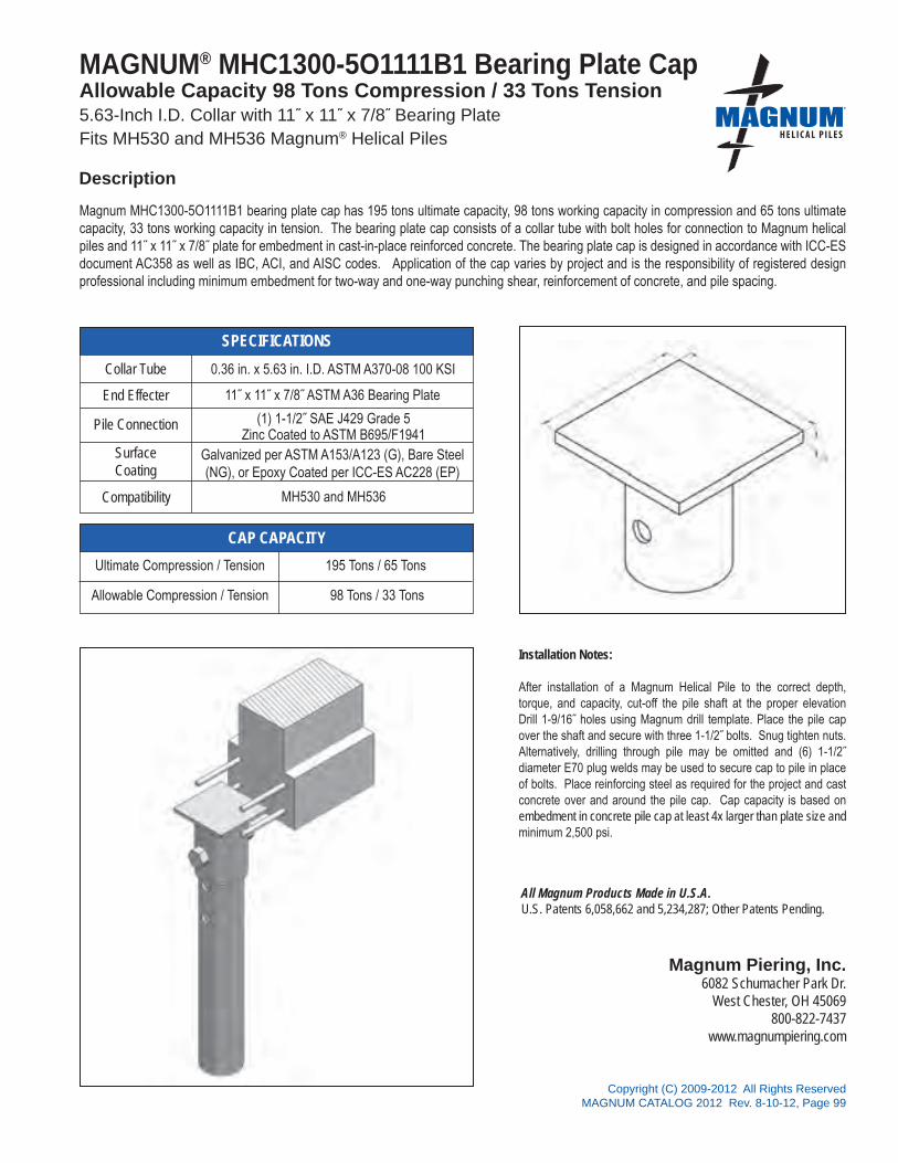
All Magnum Products Made in U.S.A.U.S. Patents 6,058,662 and 5,234,287; Other Patents Pending.
Magnum Piering, Inc.6082 Schumacher Park Dr.
West Chester, OH 45069800-822-7437
www.magnumpiering.com
Copyright (C) 2009-2012 All Rights ReservedMAGNUM CATALOG 2012 Rev. 8-10-12, Page 99
®
SPECIFICATIONS
CAP CAPACITY
MAGNUM® MHC1300-5O1111B1 Bearing Plate CapAllowable Capacity 98 Tons Compression / 33 Tons Tension 5.63-Inch I.D. Collar with 11˝ x 11˝ x 7/8˝ Bearing PlateFits MH530 and MH536 Magnum® Helical Piles
Magnum MHC1300-5O1111B1 bearing plate cap has 195 tons ultimate capacity, 98 tons working capacity in compression and 65 tons ultimate capacity, 33 tons working capacity in tension. The bearing plate cap consists of a collar tube with bolt holes for connection to Magnum helical piles and 11˝ x 11˝ x 7/8˝ plate for embedment in cast-in-place reinforced concrete. The bearing plate cap is designed in accordance with ICC-ES document AC358 as well as IBC, ACI, and AISC codes. Application of the cap varies by project and is the responsibility of registered design professional including minimum embedment for two-way and one-way punching shear, reinforcement of concrete, and pile spacing.
Installation Notes:
After installation of a Magnum Helical Pile to the correct depth, torque, and capacity, cut-off the pile shaft at the proper elevation Drill 1-9/16˝ holes using Magnum drill template. Place the pile cap over the shaft and secure with three 1-1/2˝ bolts. Snug tighten nuts.Alternatively, drilling through pile may be omitted and (6) 1-1/2˝ diameter E70 plug welds may be used to secure cap to pile in place of bolts. Place reinforcing steel as required for the project and cast concrete over and around the pile cap. Cap capacity is based on embedment in concrete pile cap at least 4x larger than plate size and minimum 2,500 psi.
(1) 1-1/2˝ SAE J429 Grade 5Zinc Coated to ASTM B695/F1941
Ultimate Compression / Tension 195 Tons / 65 Tons
Allowable Compression / Tension 98 Tons / 33 Tons
Collar Tube 0.36 in. x 5.63 in. I.D. ASTM A370-08 100 KSI
End Effecter
Pile Connection
SurfaceCoating
Galvanized per ASTM A153/A123 (G), Bare Steel(NG), or Epoxy Coated per ICC-ES AC228 (EP)
Compatibility MH530 and MH536
11˝ x 11˝ x 7/8˝ ASTM A36 Bearing Plate
Description

All Magnum Products Made in U.S.A.U.S. Patents 6,058,662 and 5,234,287; Other Patents Pending.
Magnum Piering, Inc.6082 Schumacher Park Dr.
West Chester, OH 45069800-822-7437
www.magnumpiering.com
Copyright (C) 2009-2012 All Rights ReservedMAGNUM CATALOG 2012 Rev. 8-10-12, Page 100
®
SPECIFICATIONS
CAP CAPACITY
MAGNUM® MHC1300-5O1111B3 Bearing Plate CapAllowable Capacity 98 Tons Compression / 74 Tons Tension5.63-Inch I.D. Collar with 11˝ x 11˝ x 7/8˝ Bearing PlateFits MH530 and MH536 Magnum® Helical Piles
Description
Magnum MHC1300-5O1111B3 bearing plate cap has 195 tons ultimate capacity, 98 tons working capacity in compression and 148 tons ultimate capacity, 74 tons working capacity in tension. The bearing plate cap consists of a collar tube with bolt holes for connection to Magnum helical piles and 11˝ x 11˝ x 7/8˝ plate for embedment in cast-in-place reinforced concrete. The bearing plate cap is designed in accordance with ICC-ES document AC358 as well as IBC, ACI, and AISC codes. Application of the cap varies by project and is the responsibility of registered design professional including minimum embedment for two-way and one-way punching shear, reinforcement of concrete, and pile spacing.
Installation Notes:
After installation of a Magnum Helical Pile to the correct depth, torque, and capacity, cut-off the pile shaft at the proper elevation Drill 1-9/16˝ holes using Magnum drill template. Place the pile cap over the shaft and secure with three 1-1/2˝ bolts. Snug tighten nuts Alternatively, drilling through pile may be omitted and (6) 1-1/2˝ diameter E70 plug welds may be used to secure cap to pile in place of bolts. Place reinforcing steel as required for the project and cast concrete over and around the pile cap. Cap capacity is based on embedment in concrete pile cap at least 4x larger than plate size and minimum 2,500 psi.
(3) 1-1/2˝ SAE J429 Grade 5Zinc Coated to ASTM B695/F1941
Ultimate Compression / Tension 195 Tons / 148 Tons
Allowable Compression / Tension 98 Tons / 74 Tons
Collar Tube 0.36 in. x 5.63 in. I.D. ASTM A370-08 100 KSI
End Effecter
Pile Connection
SurfaceCoating
Galvanized per ASTM A153/A123 (G), Bare Steel(NG), or Epoxy Coated per ICC-ES AC228 (EP)
Compatibility MH530 and MH536
11˝ x 11˝ x 7/8˝ ASTM A36 Bearing Plate

All Magnum Products Made in U.S.A.U.S. Patents 6,058,662 and 5,234,287; Other Patents Pending.
Magnum Piering, Inc.6082 Schumacher Park Dr.
West Chester, OH 45069800-822-7437
www.magnumpiering.com
Copyright (C) 2009-2012 All Rights ReservedMAGNUM CATALOG 2012 Rev. 8-10-12, Page 101
®
SPECIFICATIONS
CAP CAPACITY
MAGNUM® MHC1300-6L8585B1 Bearing Plate CapAllowable Capacity 52 Tons Compression / 17 Tons Tension 5.85-Inch I.D. Collar with 8.5˝ x 8.5˝ x 1/2˝ Bearing PlateFits MH625 Through MH646R Magnum® Helical Piles
Magnum MHC1300-6L8585B1 bearing plate cap has 104 tons ultimate capacity, 52 tons working capacity in compression and 35 tons ultimate capacity, 17 tons working capacity in tension. The bearing plate cap consists of a collar tube with bolt hole for connection to Magnum helical piles and 8.50˝ x 8.5˝ x 1/2˝ plate for embedment in cast-in-place reinforced concrete. The bearing plate cap is designed in accordance with ICC-ES document AC358 as well as IBC, ACI, and AISC codes. Application of the cap varies by project and is the responsibility of registered design professional including minimum embedment for two-way and one-way punching shear, reinforcement of concrete, and pile spacing.
Installation Notes:
After installation of a Magnum Helical Pile to the correct depth, torque, and capacity, cut-off the pile shaft at the proper elevation. Drill 1-9/16˝ hole using Magnum drill template. Place the pile cap over the shaft and secure with one 1-1/2˝ bolt. Snug tighten nut. Alternatively, drilling through pile may be omitted and (2) 1-1/2˝ diameter E70 plug welds may be used to secure cap to pile in place of bolts. Ensure direct bearing of plate on pile shaft. Place reinforcing steel as required for the project and cast concrete over and around the pile cap. Cap capacity is based on embedment in concrete pile cap at least 4x larger than plate size and minimum 2,500 psi.
(1) 1-1/2˝ SAE J429 Grade 5 Zinc Coated to ASTM B695/F1941
Ultimate Compression / Tension 104 Tons / 63 Tons
Allowable Compression / Tension 52 Tons / 32 Tons
Collar Tube 0.38 in. x 5.85 in. I.D. ASTM A513 GR65+
End Effecter
Pile Connection
SurfaceCoating
Galvanized per ASTM A153/A123 (G), Bare Steel(NG), or Epoxy Coated per ICC-ES AC228 (EP)
Compatibility MH625, MH625R, MH637, MH637R, MH646, andMH646R
8.5˝ x 8.5˝ x 1/2˝ Steel Bearing Plate
Description

All Magnum Products Made in U.S.A.U.S. Patents 6,058,662 and 5,234,287; Other Patents Pending.
Magnum Piering, Inc.6082 Schumacher Park Dr.
West Chester, OH 45069800-822-7437
www.magnumpiering.com
Copyright (C) 2009-2012 All Rights ReservedMAGNUM CATALOG 2012 Rev. 8-10-12, Page 102
®
SPECIFICATIONS
CAP CAPACITY
MAGNUM® MHC1300-6L8585B3 Bearing Plate CapAllowable Capacity 52 Tons Compression / 32 Tons Tension5.85-Inch I.D. Collar with 8.5˝ x 8.5˝ x 1/2˝ Bearing PlateFits MH625 Through MH646R Magnum® Helical Piles
Description
Magnum MHC1300-6L8585B3 bearing plate cap has 104 tons ultimate capacity, 52 tons working capacity in compression and 64 tons ultimate capacity, 32 tons working capacity in tension. The bearing plate cap consists of a collar tube with bolt hole for connection to Magnum helical piles and 8.5˝ x 8.5˝ x 1/2˝ plate for embedment in cast-in-place reinforced concrete. The bearing plate cap is designed in accordance with ICC-ES document AC358 as well as IBC, ACI, and AISC codes. Application of the cap varies by project and is the responsibility of registered design professional including minimum embedment for two-way and one-way punching shear, reinforcement of concrete, and pile spacing.
Installation Notes:
After installation of a Magnum Helical Pile to the correct depth, torque, and capacity, cut-off the pile shaft at the proper elevation. Drill 1-9/16” holes using Magnum drill template. Place the pile cap over the shaft and secure with three 1-1/2˝ bolts. Snug tighten nuts. Alternatively, drilling through pile may be omitted and (6) 1-1/2˝ diameter E70 plug welds may be used to secure cap to pile in place of bolts. Place reinforcing steel as required for the project and cast concrete over and around the pile cap. Cap capacity is based on embedment in concrete pile cap at least 4x larger than plate size and minimum 2,500 psi.
(3) 1-1/2˝ SAE J429 Grade 5Zinc Coated to ASTM B695/F1941
Ultimate Compression / Tension 104 Tons / 63 Tons
Allowable Compression / Tension 52 Tons / 32 Tons
Collar Tube 0.38 in. x 5.85 in. I.D. ASTM A513 GR65+
End Effecter
Pile Connection
SurfaceCoating
Galvanized per ASTM A153/A123 (G), Bare Steel(NG), or Epoxy Coated per ICC-ES AC228 (EP)
Compatibility MH625, MH625R, MH637, MH637R, MH646, andMH646R
8.5˝ x 8.5˝ x 1/2˝ Steel Bearing Plate

All Magnum Products Made in U.S.A.U.S. Patents 6,058,662 and 5,234,287; Other Patents Pending.
Magnum Piering, Inc.6082 Schumacher Park Dr.
West Chester, OH 45069800-822-7437
www.magnumpiering.com
Copyright (C) 2009-2012 All Rights ReservedMAGNUM CATALOG 2012 Rev. 8-10-12, Page 103
®
SPECIFICATIONS
CAP CAPACITY
MAGNUM® MHC1300-6M1010B1 Bearing Plate CapAllowable Capacity 75 Tons Compression / 25 Tons Tension 5.85-Inch I.D. Collar with 10˝ x 10˝ x 5/8˝ Bearing PlateFits MH625 Through MH646R Magnum® Helical Piles
Magnum MHC1300-6M1010B1 bearing plate cap has 150 tons ultimate capacity, 75 tons working capacity in compression and 50 tons ultimate capacity, 25 tons working capacity in tension. The bearing plate cap consists of a collar tube with bolt hole for connection to Magnum helical piles and 10˝ x 10˝ x 5/8˝ plate for embedment in cast-in-place reinforced concrete. The bearing plate cap is designed in accordance with ICC-ES document AC358 as well as IBC, ACI, and AISC codes. Application of the cap varies by project and is the responsibility of registered design professional including minimum embedment for two-way and one-way punching shear, reinforcement of concrete, and pile spacing.
Installation Notes:
After installation of a Magnum Helical Pile to the correct depth, torque, and capacity, cut-off the pile shaft at the proper elevation. Drill 1-9/16” hole using Magnum drill template. Place the pile cap over the shaft and secure with one 1-1/2” bolt. Snug tighten nut. Alternatively, drilling through pile may be omitted and (2) 1-1/2” diameter E70 plug welds may be used to secure cap to pile in place of bolts. Ensure direct bearing of plate on pile shaft. Place reinforcing steel as required for the project and cast concrete over and around the pile cap. Cap capacity is based on embedment in concrete pile cap at least 4x larger than plate size and minimum 2,500 psi.
(1) 1-1/2˝ SAE J429 Grade 5 Zinc Coated to ASTM B695/F1941
Ultimate Compression / Tension 150 Tons / 108 Tons
Allowable Compression / Tension 75 Tons / 54 Tons
Collar Tube 0.38 in. x 5.85 in. I.D. ASTM A513 GR65+
End Effecter
Pile Connection
SurfaceCoating
Galvanized per ASTM A153/A123 (G), Bare Steel(NG), or Epoxy Coated per ICC-ES AC228 (EP)
Compatibility MH625, MH625R, MH637, MH637R, MH646, andMH646R
10˝ x 10˝ x 5/8˝ Steel Bearing Plate
Description

All Magnum Products Made in U.S.A.U.S. Patents 6,058,662 and 5,234,287; Other Patents Pending.
Magnum Piering, Inc.6082 Schumacher Park Dr.
West Chester, OH 45069800-822-7437
www.magnumpiering.com
Copyright (C) 2009-2012 All Rights ReservedMAGNUM CATALOG 2012 Rev. 8-10-12, Page 104
®
SPECIFICATIONS
CAP CAPACITY
MAGNUM® MHC1300-6M1010B3 Bearing Plate CapAllowable Capacity 75 Tons Compression / 53 Tons Tension5.85-Inch I.D. Collar with 10˝ x 10˝ x 5/8˝ Bearing PlateFits MH625 Through MH646R Magnum® Helical Piles
Description
Magnum MHC1300-6M1010B3 bearing plate cap has 150 tons ultimate capacity, 75 tons working capacity in compression and 106 tons ultimate capacity, 53 tons working capacity in tension. The bearing plate cap consists of a collar tube with bolt hole for connection to Magnum helical piles and 10˝ x 10˝ x 5/8˝ plate for embedment in cast-in-place reinforced concrete. The bearing plate cap is designed in accordance with ICC-ES document AC358 as well as IBC, ACI, and AISC codes. Application of the cap varies by project and is the responsibility of registered design professional including minimum embedment for two-way and one-way punching shear, reinforcement of concrete, and pile spacing.
Installation Notes:
After installation of a Magnum Helical Pile to the correct depth, torque, and capacity, cut-off the pile shaft at the proper elevation. Drill 1-9/16˝ holes using Magnum drill template. Place the pile cap over the shaft and secure with three 1-1/2˝ bolts. Snug tighten nuts. Alternatively, drilling through pile may be omitted and (6) 1-1/2˝ diameter E70 plug welds may be used to secure cap to pile in place of bolts. Place reinforcing steel as required for the project and cast concrete over and around the pile cap. Cap capacity is based on embedment in concrete pile cap at least 4x larger than plate size and minimum 2,500 psi.
(3) 1-1/2˝ SAE J429 Grade 5 Zinc Coated to ASTM B695/F1941
Ultimate Compression / Tension 150 Tons / 106 Tons
Allowable Compression / Tension 75 Tons / 53 Tons
Collar Tube 0.38 in. x 5.85 in. I.D. ASTM A513 GR65+
End Effecter
Pile Connection
SurfaceCoating
Galvanized per ASTM A153/A123 (G), Bare Steel(NG), or Epoxy Coated per ICC-ES AC228 (EP)
Compatibility MH625, MH625R, MH637, MH637R, MH646, andMH646R
10˝ x 10˝ x 5/8˝ Steel Bearing Plate

All Magnum Products Made in U.S.A.U.S. Patents 6,058,662 and 5,234,287; Other Patents Pending.
Magnum Piering, Inc.6082 Schumacher Park Dr.
West Chester, OH 45069800-822-7437
www.magnumpiering.com
Copyright (C) 2009-2012 All Rights ReservedMAGNUM CATALOG 2012 Rev. 8-10-12, Page 105
®
SPECIFICATIONS
CAP CAPACITY
MAGNUM® MHC1300-6N1111B1 Bearing Plate CapAllowable Capacity 95 Tons Compression / 32 Tons Tension 5.85-Inch I.D. Collar with 11˝ x 11˝ x 3/4˝ Bearing PlateFits MH625 Through MH646R Magnum® Helical Piles
Magnum MHC1300-NE1111B1 bearing plate cap has 191 tons ultimate capacity, 95 tons working capacity in compression and 64 tons ultimate capacity, 32 tons working capacity in tension. The bearing plate cap consists of a collar tube with bolt hole for connection to Magnum helical piles and 11˝ x 11˝ x 3/4˝ plate for embedment in cast-in-place reinforced concrete. The bearing plate cap is designed in accordance with ICC-ES document AC358 as well as IBC, ACI, and AISC codes. Application of the cap varies by project and is the responsibility of registered design professional including minimum embedment for two-way and one-way punching shear, reinforcement of concrete, and pile spacing.
Installation Notes:
After installation of a Magnum Helical Pile to the correct depth, torque, and capacity, cut-off the pile shaft at the proper elevation. Drill 1-9/16˝ hole using Magnum drill template. Place the pile cap over the shaft and secure with one 1-1/2˝ bolt. Snug tighten nut. Alternatively, drilling through pile may be omitted and (2) 1-1/2˝ diameter E70 plug welds may be used to secure cap to pile in place of bolts. Ensure direct bearing of plate on pile shaft. Place reinforcing steel as required for the project and cast concrete over and around the pile cap. Cap capacity is based on embedment in concrete pile cap at least 4x larger than plate size and minimum 2,500 psi.
(1) 1-1/2˝ SAE J429 Grade 5 Zinc Coated to ASTM B695/F1941
Ultimate Compression / Tension 191 Tons / 146 Tons
Allowable Compression / Tension 95 Tons / 73 Tons
Collar Tube 0.38 in. x 5.85 in. I.D. ASTM A513 GR65+
End Effecter
Pile Connection
SurfaceCoating
Galvanized per ASTM A153/A123 (G), Bare Steel(NG), or Epoxy Coated per ICC-ES AC228 (EP)
Compatibility MH625, MH625R, MH637, MH637R, MH646, andMH646R
11˝ x 11˝ x 3/4˝ Steel Bearing Plate
Description
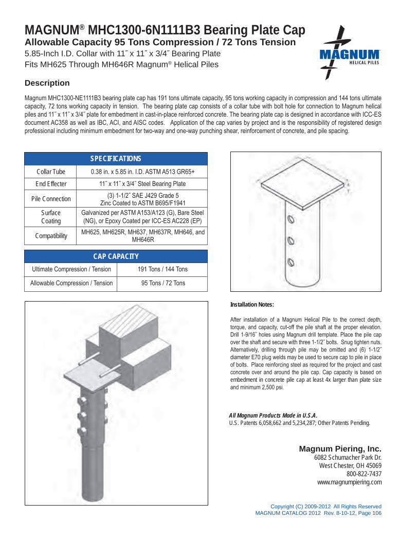
All Magnum Products Made in U.S.A.U.S. Patents 6,058,662 and 5,234,287; Other Patents Pending.
Magnum Piering, Inc.6082 Schumacher Park Dr.
West Chester, OH 45069800-822-7437
www.magnumpiering.com
Copyright (C) 2009-2012 All Rights ReservedMAGNUM CATALOG 2012 Rev. 8-10-12, Page 106
®
SPECIFICATIONS
CAP CAPACITY
MAGNUM® MHC1300-6N1111B3 Bearing Plate CapAllowable Capacity 95 Tons Compression / 72 Tons Tension5.85-Inch I.D. Collar with 11˝ x 11˝ x 3/4˝ Bearing PlateFits MH625 Through MH646R Magnum® Helical Piles
Description
Magnum MHC1300-NE1111B3 bearing plate cap has 191 tons ultimate capacity, 95 tons working capacity in compression and 144 tons ultimate capacity, 72 tons working capacity in tension. The bearing plate cap consists of a collar tube with bolt hole for connection to Magnum helical piles and 11˝ x 11˝ x 3/4˝ plate for embedment in cast-in-place reinforced concrete. The bearing plate cap is designed in accordance with ICC-ES document AC358 as well as IBC, ACI, and AISC codes. Application of the cap varies by project and is the responsibility of registered design professional including minimum embedment for two-way and one-way punching shear, reinforcement of concrete, and pile spacing.
Installation Notes:
After installation of a Magnum Helical Pile to the correct depth, torque, and capacity, cut-off the pile shaft at the proper elevation. Drill 1-9/16˝ holes using Magnum drill template. Place the pile cap over the shaft and secure with three 1-1/2˝ bolts. Snug tighten nuts. Alternatively, drilling through pile may be omitted and (6) 1-1/2˝ diameter E70 plug welds may be used to secure cap to pile in place of bolts. Place reinforcing steel as required for the project and cast concrete over and around the pile cap. Cap capacity is based on embedment in concrete pile cap at least 4x larger than plate size and minimum 2,500 psi.
(3) 1-1/2˝ SAE J429 Grade 5Zinc Coated to ASTM B695/F1941
Ultimate Compression / Tension 191 Tons / 144 Tons
Allowable Compression / Tension 95 Tons / 72 Tons
Collar Tube 0.38 in. x 5.85 in. I.D. ASTM A513 GR65+
End Effecter
Pile Connection
SurfaceCoating
Galvanized per ASTM A153/A123 (G), Bare Steel(NG), or Epoxy Coated per ICC-ES AC228 (EP)
Compatibility MH625, MH625R, MH637, MH637R, MH646, andMH646R
11˝ x 11˝ x 3/4˝ Steel Bearing Plate

All Magnum Products Made in U.S.A.U.S. Patents 6,058,662 and 5,234,287; Other Patents Pending.
Magnum Piering, Inc.6082 Schumacher Park Dr.
West Chester, OH 45069800-822-7437
www.magnumpiering.com
Copyright (C) 2009-2012 All Rights ReservedMAGNUM CATALOG 2012 Rev. 8-10-12, Page 107
®
SPECIFICATIONS
CAP CAPACITY
MAGNUM® MHC1300-8N1212B1 Bearing Plate CapAllowable Capacity 133 Tons Compression / 44 Tons Tension8.75-Inch I.D. Collar with 12˝ x 12˝ x 3/4˝ Bearing Plate Fits MH832B and MH850B Magnum® Helical Piles
Description
Magnum MHC1300-8N1212B1 bearing plate cap has 266 tons ultimate capacity, 133 tons working capacity in compression and 88 tons ultimate capacity, 44 tons working capacity in tension. The bearing plate cap consists of a collar tube with bolt hole for connection to Magnum helical piles and 12˝ x 12˝ x 3/4˝ plate for embedment in cast-in-place reinforced concrete. The bearing plate cap is designed in accordance with ICC-ES document AC358 as well as IBC, ACI, and AISC codes. Application of the cap varies by project and is the responsibility of registered design professional including minimum embedment for two-way and one-way punching shear, reinforcement of concrete, and pile spacing.
Installation Notes:
After installation of a Magnum Helical Pile to the correct depth, torque, and capacity, cut-off the pile shaft at the proper elevation. Drill 1-9/16˝ holes using Magnum drill template. Place the pile cap over the shaft and secure with three 1-1/2˝ bolts. Snug tighten nuts. Alternatively, drilling through pile may be omitted and (6) 1-1/2˝ diameter E70 plug welds may be used to secure cap to pile in place of bolts. Place reinforcing steel as required for the project and cast concrete over and around the pile cap. Cap capacity is based on embedment in concrete pile cap at least 4x larger than plate size and minimum 2,500 psi. .
(1) 2˝ SAE J429 Grade 5 Zinc Coated to ASTM B695/F194
Ultimate Compression / Tension 266 Tons / 88 Tons
Allowable Compression / Tension 133 Tons / 44 Tons
Collar Tube 0.5 in. x 8.75 in. I.D. ASTM A513 GR65+
End Effecter
Pile Connection
SurfaceCoating
Galvanized per ASTM A153/A123 (G), Bare Steel(NG), or Epoxy Coated per ICC-ES AC228 (EP)
Compatibility MH832B and MH850B
12˝ x 12˝ x 3/4˝ Steel Bearing Plate

All Magnum Products Made in U.S.A.U.S. Patents 6,058,662 and 5,234,287; Other Patents Pending.
Magnum Piering, Inc.6082 Schumacher Park Dr.
West Chester, OH 45069800-822-7437
www.magnumpiering.com
Copyright (C) 2009-2012 All Rights ReservedMAGNUM CATALOG 2012 Rev. 8-10-12, Page 108
®
SPECIFICATIONS
CAP CAPACITY
MAGNUM® MHC1350-5N6135B1 Gusseted CapAllowable Capacity 98 Tons Compression / 33 Tons Tension 5.63-Inch I.D. Collar with 6˝ x 13.5˝ x 3/4˝ Bearing PlateFits MH530 and MH536 Magnum® Helical Piles
Magnum MHC1350-5N6135B1 gusseted cap has 195 tons ultimate capacity, 98 tons working capacity in compression and 65 tons ultimate capacity, 33 tons working capacity in tension. The gusseted cap consists of a collar tube with bolt holes for connection to Magnum helical piles and 6˝ x 13.5˝ x 3/4˝ plate for embedment in cast-in-place reinforced concrete. The gusseted cap is designed in accordance with ICC-ES document AC358 as well as IBC, ACI, and AISC codes. Application of the cap varies by project and is the responsibility of registered design professional including minimum embedment for two-way and one-way punching shear, reinforcement of concrete, and pile spacing.
Installation Notes:
After installation of a Magnum Helical Pile to the correct depth, torque, and capacity, cut-off the pile shaft at the proper elevation. Drill 1-9/16˝ holes using Magnum drill template. Place the pile cap over the shaft and secure with one 1-1/2˝ bolt. Snug tighten nut. Alternatively, drilling through pile may be omitted and (2) 1-1/2˝ diameter E70 plug welds may be used to secure cap to pile in place of bolts. Ensure direct bearing of plate on pile shaft. Place reinforcing steel as required for the project and cast concrete over and around the pile cap. Cap capacity is based on embedment in concrete pile cap at least 4x larger than plate size and minimum 2,500 psi concrete.
(1) 1-1/2˝ SAE J429 Grade 5Zinc Coated to ASTM B695/F1941
Ultimate Compression / Tension 195 Tons / 65 Tons
Allowable Compression / Tension 98 Tons / 33 Tons
Collar Tube 0.30 in. x 5.63 in. I.D. ASTM A370-08 100KSI
End Effecter
Pile Connection
SurfaceCoating
Galvanized per ASTM A153/A123 (G), Bare Steel(NG), or Epoxy Coated per ICC-ES AC228 (EP)
Compatibility MH530 and MH536
6˝ x 13.5˝ x 3/4˝ Steel Bearing Plate with Support Gussets
Description
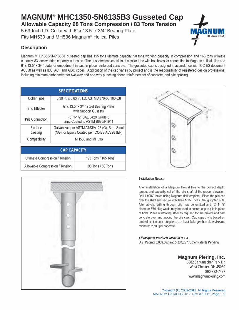
All Magnum Products Made in U.S.A.U.S. Patents 6,058,662 and 5,234,287; Other Patents Pending.
Magnum Piering, Inc.6082 Schumacher Park Dr.
West Chester, OH 45069800-822-7437
www.magnumpiering.com
Copyright (C) 2009-2012 All Rights ReservedMAGNUM CATALOG 2012 Rev. 8-10-12, Page 109
®
SPECIFICATIONS
CAP CAPACITY
MAGNUM® MHC1350-5N6135B3 Gusseted CapAllowable Capacity 98 Tons Compression / 83 Tons Tension5.63-Inch I.D. Collar with 6˝ x 13.5˝ x 3/4˝ Bearing PlateFits MH530 and MH536 Magnum® Helical Piles
Description
Magnum MHC1350-5N6135B1 gusseted cap has 195 tons ultimate capacity, 98 tons working capacity in compression and 165 tons ultimate capacity, 83 tons working capacity in tension. The gusseted cap consists of a collar tube with bolt holes for connection to Magnum helical piles and 6˝ x 13.5˝ x 3/4˝ plate for embedment in cast-in-place reinforced concrete. The gusseted cap is designed in accordance with ICC-ES document AC358 as well as IBC, ACI, and AISC codes. Application of the cap varies by project and is the responsibility of registered design professional including minimum embedment for two-way and one-way punching shear, reinforcement of concrete, and pile spacing.
Installation Notes:
After installation of a Magnum Helical Pile to the correct depth, torque, and capacity, cut-off the pile shaft at the proper elevation. Drill 1-9/16˝ holes using Magnum drill template. Place the pile cap over the shaft and secure with three 1-1/2˝ bolts. Snug tighten nuts. Alternatively, drilling through pile may be omitted and (6) 1-1/2˝ diameter E70 plug welds may be used to secure cap to pile in place of bolts. Place reinforcing steel as required for the project and cast concrete over and around the pile cap. Cap capacity is based on embedment in concrete pile cap at least 4x larger than plate size and minimum 2,500 psi concrete.
(3) 1-1/2˝ SAE J429 Grade 5Zinc Coated to ASTM B695/F1941
Ultimate Compression / Tension 195 Tons / 165 Tons
Allowable Compression / Tension 98 Tons / 83 Tons
Collar Tube 0.30 in. x 5.63 in. I.D. ASTM A370-08 100KSI
End Effecter
Pile Connection
SurfaceCoating
Galvanized per ASTM A153/A123 (G), Bare Steel(NG), or Epoxy Coated per ICC-ES AC228 (EP)
Compatibility MH530 and MH536
6˝ x 13.5˝ x 3/4˝ Steel Bearing Plate with Support Gussets

All Magnum Products Made in U.S.A.U.S. Patents 6,058,662 and 5,234,287; Other Patents Pending.
Magnum Piering, Inc.6082 Schumacher Park Dr.
West Chester, OH 45069800-822-7437
www.magnumpiering.com
Copyright (C) 2009-2012 All Rights ReservedMAGNUM CATALOG 2012 Rev. 8-10-12, Page 110
®
SPECIFICATIONS
CAP CAPACITY
MAGNUM® MHC1420-3N1212BR Tilted Plate CapAllowable Capacity 25 Tons Compression / 25 Tons Tension 3.13-Inch I.D. Collar with 12˝ x 12˝ x 3/4˝ Bearing Plate Tilted 20 DegreesFits MH325R Magnum® Helical Piles
Magnum MHC1420-3N1212BR bearing plate cap has 50 tons ultimate capacity, 25 tons working capacity in compression and tension. The bearing plate cap consists of a collar tube with bolt holes for connection to Magnum helical piles and 12˝ x 12˝ x 3/4˝ plate battered 20 degrees for attachment to a steel beam. The bearing plate cap is designed in accordance with ICC-ES document AC358 as well as IBC, ACI, and AISC codes. Application of the cap varies by project and is the responsibility of registered design professional including beam attachment, beam shear, beam span, web stiffening, bracing, and pile spacing as applicable.
Installation Notes:
After installation of a Magnum Helical Pile to the correct depth, torque, and capacity, cut-off the pile shaft at the proper elevation. For Bolted “B” application, drill two 1.06˝ holes using Magnum drill template. Place the pile cap over the shaft and secure with two 1˝ bolts. Snug tighten nuts. For Welded “W” application, plug weld cap in place through manufactured drill holes. Remove surface coating from plug weld areas. Place steel beam on cap and weld per project specifications.
(2) 1˝ SAE J429 Grade 5Zinc Coated to ASTM B695/F1941
Ultimate Compression / Tension 50 Tons / 50 Tons
Allowable Compression / Tension 25 Tons / 25 Tons
Collar Tube 0.31 in. x 3.13 in. I.D. ASTM A513 GR65+
End Effecter
Pile Connection
SurfaceCoating
Galvanized per ASTM A153/A123 (G), Bare Steel(NG), or Epoxy Coated per ICC-ES AC228 (EP)
Compatibility MH325R
12˝ x 12˝ x 3/4˝ Steel Bearing PlateTilted 20 Degrees
Description
Note: Cap capacity takes into account strength of collar, end effecter, and pile connection. Capacity may be limited by the helical pile itself, bearing/pullout capacity of soil, or strength of the structure to which the cap is attached, whichever is less.
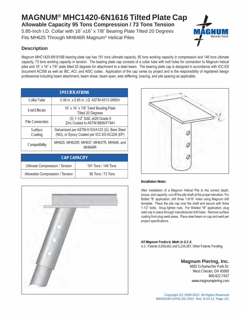
All Magnum Products Made in U.S.A.U.S. Patents 6,058,662 and 5,234,287; Other Patents Pending.
Magnum Piering, Inc.6082 Schumacher Park Dr.
West Chester, OH 45069800-822-7437
www.magnumpiering.com
Copyright (C) 2009-2012 All Rights ReservedMAGNUM CATALOG 2012 Rev. 8-10-12, Page 111
®
SPECIFICATIONS
CAP CAPACITY
MAGNUM® MHC1420-6N1616 Tilted Plate Cap Allowable Capacity 95 Tons Compression / 73 Tons Tension5.85-Inch I.D. Collar with 16˝ x16˝ x 7/8˝ Bearing Plate Tilted 20 DegreesFits MH625 Through MH646R Magnum® Helical Piles
Description
Magnum MHC1420-6N1616B bearing plate cap has 191 tons ultimate capacity, 95 tons working capacity in compression and 146 tons ultimate capacity, 73 tons working capacity in tension. The bearing plate cap consists of a collar tube with bolt holes for connection to Magnum helical piles and 16˝ x 16˝ x 7/8˝ plate tilted 20 degrees for attachment to a steel beam. The bearing plate cap is designed in accordance with ICC-ES document AC358 as well as IBC, ACI, and AISC codes. Application of the cap varies by project and is the responsibility of registered design professional including beam attachment, beam shear, beam span, web stiffening, bracing, and pile spacing as applicable.
Installation Notes:
After installation of a Magnum Helical Pile to the correct depth, torque, and capacity, cut-off the pile shaft at the proper elevation. For Bolted “B” application, drill three 1-9/16˝ holes using Magnum drill template. Place the pile cap over the shaft and secure with three 1-1/2˝ bolts. Snug tighten nuts. For Welded “W” application, plug weld cap in place through manufactured drill holes. Remove surface coating from plug weld areas. Place steel beam on cap and weld per project specifications.
(3) 1-1/2˝ SAE J429 Grade 5Zinc Coated to ASTM B695/F1941
Ultimate Compression / Tension 191 Tons / 146 Tons
Allowable Compression / Tension 95 Tons / 73 Tons
Collar Tube 0.38 in. x 5.85 in. I.D. ASTM A513 GR65+
End Effecter
Pile Connection
SurfaceCoating
Galvanized per ASTM A153/A123 (G), Bare Steel(NG), or Epoxy Coated per ICC-ES AC228 (EP)
Compatibility
16˝ x 16˝ x 7/8˝ Steel Bearing PlateTilted 20 Degrees
MH625, MH625R, MH637, MH637R, MH646, andMH646R

All Magnum Products Made in U.S.A.U.S. Patents 6,058,662 and 5,234,287; Other Patents Pending.
Magnum Piering, Inc.6082 Schumacher Park Dr.
West Chester, OH 45069800-822-7437
www.magnumpiering.com
Copyright (C) 2009-2012 All Rights ReservedMAGNUM CATALOG 2012 Rev. 8-10-12, Page 112
®
Total Horizontal Thrust Resistance = 8 Tons
SPECIFICATIONS
CAP CAPACITY
MAGNUM® MHC1530-3N68 Panel Brace CapAllowable Capacity 16 Tons Compression / 16 Tons Tension 3.13-Inch I.D. Collar with 6˝ x 8˝ x 3/4˝ Plate Tilted 30 Degrees with ¾˝ StudFits MH313B, MH313BR, and MH325B Magnum® Helical Piles
Magnum MHC1530-3N68 panel brace cap has 32 tons ultimate capacity, 16 tons working capacity in compression and tension. The bearing plate cap consists of a collar tube with bolt holes for connection to Magnum helical piles and 6˝ x 8˝ x 3/4˝ plate tilted 30 degrees with a ¾˝ stud for attachment to common pre-cast concrete or tilt-up panel braces. The bearing plate cap is designed in accordance with ICC-ES document AC358 as well as IBC, ACI, and AISC codes. Application of the cap varies by project and is the responsibility of registered design professional including brace attachment, brace spacing, and brace height on the wall, as applicable.
Installation Notes:
After installation of a Magnum Helical Pile to the correct depth, torque, and capacity, stop the shaft at the correct elevation or cut-off the pile shaft at the proper elevation. If necessary, drill one 15/16˝ hole using Magnum drill template. Place the pile cap over the shaft and secure with one 7/8˝ bolt. Snug tighten nut. Connect wall brace per brace manufacturer specifications.
(1) 7/8˝ SAE J429 Grade 5 Zinc Coated to ASTM B695/F1941
Ultimate Compression / Tension 32 Tons / 32 Tons
Allowable Compression / Tension 16 Tons / 16 Tons
Collar Tube 0.25 in. x 3.13 in. I.D. ASTM A513 GR65+
End Effecter
Pile Connection
SurfaceCoating
Galvanized per ASTM A153/A123 (G), Bare Steel(NG), or Epoxy Coated per ICC-ES AC228 (EP)
Compatibility MH325B
6˝ x 8˝ x 3/4˝ Steel Bearing Plate Tilted 30 Degrees with Threaded Attachment Stud
Description
Note: Cap capacity takes into account strength of collar, end effecter, and pile connection. Capacity may be limited by the helical pile itself, bearing/pullout capacity of soil, or strength of the structure to which the cap is attached, whichever is less.

All Magnum Products Made in U.S.A.U.S. Patents 6,058,662 and 5,234,287; Other Patents Pending.
Magnum Piering, Inc.6082 Schumacher Park Dr.
West Chester, OH 45069800-822-7437
www.magnumpiering.com
Copyright (C) 2009-2012 All Rights ReservedMAGNUM CATALOG 2012 Rev. 8-10-12, Page 113
®
Total Horizontal Thrust Resistance = 11 Tons
SPECIFICATIONS
CAP CAPACITY
MAGNUM® MHC1545-3N68 Panel Brace CapAllowable Capacity 16 Tons Compression / 16 Tons Tension 3.13-Inch I.D. Collar with 6˝ x 8˝ x 3/4˝ Plate Tilted 45 Degrees with ¾˝ StudFits MH313B, MH313BR, and MH325B Magnum® Helical Piles
Magnum MHC1545-3N68 panel brace cap has 32 tons ultimate capacity, 16 tons working capacity in compression and tension. The bearing plate cap consists of a collar tube with bolt holes for connection to Magnum helical piles and 6˝ x 8˝ x 3/4˝ plate tilted 45 degrees with a ¾˝ stud for attachment to common pre-cast concrete or tilt-up panel braces. The bearing plate cap is designed in accordance with ICC-ES document AC358 as well as IBC, ACI, and AISC codes. Application of the cap varies by project and is the responsibility of registered design professional including brace attachment, brace spacing, and brace height on the wall, as applicable.
Installation Notes:
After installation of a Magnum Helical Pile to the correct depth, torque, and capacity, stop the shaft at the correct elevation or cut-off the pile shaft at the proper elevation. If necessary, drill one 15/16˝hole using Magnum drill template. Place the pile cap over the shaft and secure with one 7/8˝ bolt. Snug tighten nut. Connect wall brace per brace manufacturer specifications.
(1) 7/8˝ SAE J429 Grade 5Zinc Coated to ASTM B695/F1941
Ultimate Compression / Tension 32 Tons / 32 Tons
Allowable Compression / Tension 16 Tons / 16 Tons
Collar Tube 0.25 in. x 3.13 in. I.D. ASTM A513 GR65+
End Effecter
Pile Connection
SurfaceCoating
Galvanized per ASTM A153/A123 (G), Bare Steel(NG), or Epoxy Coated per ICC-ES AC228 (EP)
Compatibility MH325B
6˝ x 8˝ x 3/4˝ Steel Bearing Plate Tilted 45 Degrees with Threaded Attachment Stud
Description
Note: Cap capacity takes into account strength of collar, end effecter, and pile connection. Capacity may be limited by the helical pile itself, bearing/pullout capacity of soil, or strength of the structure to which the cap is attached, whichever is less.

®
Copyright (C) 2009-2012 All Rights ReservedMAGNUM CATALOG 2012 Rev. 8-10-12, Page 115
MA
GN
UM
PIERIN
G, IN
C.s e c t i o n 4
DRIVE TOOLS & HOLE TEMPLATES

Copyright (C) 2009-2012 All Rights ReservedMAGNUM CATALOG 2012 Rev. 8-10-12, Page 116
Mag
num
®
Driv
e To
ols
Des
crip
tion
Fits
Hel
ical
Pile
Dia
m.
(in)
Fits
D
rive
Shaf
tSi
ze*
(in)
Driv
e Pi
nsC
onne
ctio
nB
olts
Max
imum
To
rque
(ft-lb
s)
Surf
ace
Coa
ting*
*Sc
hem
atic
MSA
150-
2000
Driv
e To
ol fo
r 1.5
" Sq
uare
-Sha
ftM
S150
B2"
Hex
(1)
7/8"
or
(1
) 1"
(1)
9,00
0P
MSA
175-
2000
Driv
e To
ol fo
r 1.
75" S
quar
e Sh
aft
MS1
75B
2" H
ex(1
) 7/
8" o
r
(1) 1
"(1
)9,
000
P
MH
A20
00Lo
w-T
orqu
e
D
rive
Tool
MH
313B
, MH
-31
3BR
, MH
325B
, M
H32
5BR
2" H
ex(1
) 7/8
" or
(1
) 1"
(1)
9,00
0P
MH
A21
00H
igh-
Torq
ueD
rive
Tool
MH
313,
MH
313R
,M
H32
5 M
H32
5R2.
5˝ H
ex(1
) 7/8
˝ or
(1) 1
˝(1
)13
,000
P
MH
A21
35H
igh-
Torq
ueD
rive
Tool
MH
3521
, MH
3521
R2.
5˝ H
ex(1
) 1˝
(1)
13,0
00P
MH
A22
00H
igh-
Torq
ueD
rive
Tool
MH
313,
MH
313R
,M
H32
5 M
H32
5R2-
5/8˝
Hex
(1) 7
/8˝ o
r(1
) 1˝
(1)
13,0
00P
MH
A23
00H
igh-
Torq
ueD
rive
Tool
MH
313,
MH
313R
,M
H32
5 M
H32
5R3˝
Hex
(1) 7
/8˝ o
r(1
) 1˝
(1)
13,0
00P
Sys
tem
Rat
ings
& S
peci
ficat
ions
Mag
num
® P
ieri
ngD
rive
Too
ls®

Copyright (C) 2009-2012 All Rights ReservedMAGNUM CATALOG 2012 Rev. 8-10-12, Page 117
Mag
num
®
Driv
e To
ols
Des
crip
tion
Fits
Hel
ical
Pile
Dia
m.
(in)
Fits
D
rive
Shaf
tSi
ze*
(in)
Driv
e Pi
nsC
onne
ctio
nB
olts
Max
imum
To
rque
(ft-lb
s)
Surf
ace
Coa
ting*
*Sc
hem
atic
MH
A22
42Lo
w-T
orqu
eD
rive
Tool
MH
425,
MH
425R
,M
H43
1, M
H43
1R2-
5/8˝
Hex
(2) 1
.25˝
(1)
13,0
00P
MH
A21
45M
ediu
m-T
orqu
eD
rive
Tool
MH
425,
MH
425R
,M
H43
1, M
H43
1R3˝
Hex
(2) 1
.25˝
(1) 1
˝25
,000
P
MH
A22
70To
rque
Tra
nsdu
cer
Adap
ters
Vario
us3˝
to 4
˝Sq
uare
Varie
s(1
) 1-1
/8˝
up to
83,0
00P
MH
A22
45H
igh-
Torq
ueD
rive
Tool
MH
425,
MH
425R
,M
H43
1, M
H43
1R4˝
Squ
are
(2) 1
.25˝
(1) 1
-1/8
˝35
,000
P
Sys
tem
Rat
ings
& S
peci
ficat
ions
Mag
num
® P
ieri
ngD
rive
Too
ls (
Con
t.)
®

Copyright (C) 2009-2012 All Rights ReservedMAGNUM CATALOG 2012 Rev. 8-10-12, Page 118
Mag
num
®
Driv
e To
ols
Des
crip
tion
Fits
Hel
ical
Pile
Dia
m.
(in)
Fits
D
rive
Shaf
tSi
ze*
(in)
Driv
e Pi
nsC
onne
ctio
nB
olts
Max
imum
To
rque
(ft-lb
s)
Surf
ace
Coa
ting*
*Sc
hem
atic
MH
A24
60D
rive
Tool
for
MH
530/
MH
536
MH
530,
MH
536
5˝ S
quar
e(3
) 1.5
˝(1
) 1-1
/8˝
83,0
00P
MH
A23
45D
rive
Tool
for
MH
6 / M
H6R
MH
625,
MH
625R
,M
H63
7, M
H63
7R,
MH
646,
MH
646R
5˝ S
quar
e(3
) 1.5
˝(1
) 1-1
/8˝
83,0
00P
Sys
tem
Rat
ings
& S
peci
ficat
ions
Mag
num
® P
ieri
ngD
rive
Too
ls (
Con
t.)
*N
ote
1 H
ex d
rive
size
is m
easu
red
acro
ss fl
ats.
All
Mag
num
driv
e to
ols
are
case
har
dene
d fo
r max
imum
dur
abilit
y af
ter f
abric
atio
n.
**N
ote
2 P=
Mag
num
blu
e pa
int
Not
es a
nd S
peci
ficat
ions
As
Mag
num
is c
omm
itted
to te
stin
g an
d im
prov
ing
prod
ucts
, the
se s
peci
ficat
ions
are
sub
ject
to c
hang
e. A
dditi
onal
pro
duct
spe
cific
atio
ns a
vaila
ble
at
ww
wm
agnu
mpi
erin
g.co
m, i
n th
e M
agnu
m P
rodu
ct C
atal
og, a
nd in
the
Mag
num
Hel
ical
Pile
Eng
inee
ring
Man
ual.
®

Copyright (C) 2009-2012 All Rights ReservedMAGNUM CATALOG 2012 Rev. 8-10-12, Page 119
Mag
num
®
Dril
l Tem
plat
esD
escr
iptio
nFi
ts H
elic
alPi
le D
iam
.(in
)
Bol
t Hol
e Pa
ttern
Surf
ace
Coa
ting*
*Sc
hem
atic
MH
A50
10M
H3
Bolt
Hol
e Te
mpl
ate
3.00
(1) 7
/8˝
NG
, P
MH
A50
20M
H3R
Bol
t Hol
e Te
mpl
ate
3.00
(2) 1
˝N
G, P
MH
A50
40M
H35
21R
Bol
t Hol
e Te
mpl
ate
3.50
(2) 1
˝N
G, P
MH
A50
00M
H4
Bolt
Hol
e Te
mpl
ate
4.50
(2) 1
.25˝
NG
, P
Sys
tem
Rat
ings
& S
peci
ficat
ions
Mag
num
® P
ieri
ngD
rill
Tem
plat
es®

Copyright (C) 2009-2012 All Rights ReservedMAGNUM CATALOG 2012 Rev. 8-10-12, Page 120
Mag
num
®
Dril
l Tem
plat
esD
escr
iptio
nFi
ts H
elic
alPi
le D
iam
.(in
)
Bol
t Hol
e Pa
ttern
Surf
ace
Coa
ting*
*Sc
hem
atic
MH
A50
50M
H6
Bolt
Hol
e Te
mpl
ate
5.72
(3) 1
.5˝
NG
, P
MH
A50
30M
H6
Bolt
Hol
e Te
mpl
ate
5.72
(3) 1
.5˝
NG
, P
Sys
tem
Rat
ings
& S
peci
ficat
ions
Mag
num
® P
ieri
ngD
rill
Tem
plat
es (
Con
t.)
**
Not
e N
G=b
are
stee
l, P=
Mag
num
blu
e pa
int
Not
es a
nd S
peci
ficat
ions
As
Mag
num
is c
omm
itted
to te
stin
g an
d im
prov
ing
prod
ucts
, the
se s
peci
ficat
ions
are
sub
ject
to c
hang
e. A
dditi
onal
pro
duct
spe
cific
atio
ns a
vaila
ble
at w
ww
.mag
num
pier
ing.
com
, in
the
Mag
num
Pro
duct
Cat
alog
, an
d in
the
Mag
num
Hel
ical
Pile
Eng
inee
ring
Man
ual a
vaila
ble
upon
requ
est.
®

Copyright (C) 2009-2012 All Rights ReservedMAGNUM CATALOG 2012 Rev. 8-10-12, Page 121
®
Magnum Piering, Inc.6082 Schumacher Park Dr.
West Chester, OH 45069800-822-7437
www.magnumpiering.com
MAGNUM® MHA4010-2Foot Operated Hydraulic Control 3,500 psi Maximum PressureControl Assembly for Torque Motors
The MAGNUM MHA4010-2 is a foot operated hydraulic control for operation of a variety of torque motors. The device enables hands free operation and has applications for foundation repair and augmentation using helical piles. It is beneficial in the operation of torque motors inside existing structures using an external hydraulic power pack and portable torque motors without heavy equipment. The pedal is bi-directional for control of forward and reverse rotation. Twin hydraulic gauges measure input pressure and back pressure for determination of motor torque.
Description
Note: Torque motors have differing hydraulic pressure and flow requirements. Consult a MAGNUM technical support representative for assistance in determining compatibility of the MHA4010-2 with specific torque motors.
All Magnum Steel & Products Made in U.S.A.U.S. Patents 6,058,662 and 5,234,287; Other Patents Pending.
Pedal Guard
Hydraulic Gauges
Hydraulic Valve Assy
Roll Bar/Handle
Base Plate
Pedal Sub Assembly

®
Copyright (C) 2009-2012 All Rights ReservedMAGNUM CATALOG 2012 Rev. 8-10-12, Page 123
MA
GN
UM
PIERIN
G, IN
C.
s e c t i o n 5
FOUNDATION BRACKETS

Copyright (C) 2009-2012 All Rights ReservedMAGNUM CATALOG 2012 Rev. 8-10-12, Page 124
Part
No.
MP
1001
3-
G
Expl
anat
ion:
The
Mag
num
Pie
ring
Foun
datio
n Br
acke
t pro
duct
num
ber a
bove
MP1
001-
3G is
for a
Pla
te B
rack
et w
ith 3
.00˝
insi
de d
iam
eter
col
lar t
ube,
and
the
surfa
ce p
repa
ratio
n is
Gal
vani
zed.
Not
e: S
ee “M
agnu
m P
ierin
g Fo
unda
tion
Brac
ket S
peci
ficat
ions
” tab
le o
n ne
xt p
age
for d
etai
led
info
rmat
ion.
Spe
cific
atio
n in
form
atio
n is
als
o av
aila
ble
at w
ww
.mag
num
pier
ing.
com
Mag
num
Pie
ring,
Inc.
ISO
900
1:20
08C
ertifi
ed
Mag
num
® F
ound
atio
n B
rack
etP
rodu
ct N
umbe
r S
peci
ficat
ion
Lege
nd
Unique Numeric Designation for Bracket Style
Magnum Piering Foundation Bracket (MP)
Collar Inside Diameter fits Helical Pile and Push Pier Shafts with
Outside Diameters of (2
)=1.75˝, (3)=3.0˝, (4
)=4.5˝
(G) Galvanized, (NG) Non-Galvanized, or (E
P) Epoxy Powder Coated
®

Copyright (C) 2009-2012 All Rights ReservedMAGNUM CATALOG 2012 Rev. 8-10-12, Page 125
Mag
num
®
Bra
cket
sN
ame
Fits
Pile
Dia
m.
(in)
No.
Bol
ts /
Thru
Hol
es
Bol
t ho
leD
iam
.(in
)
Stru
ctur
al C
apac
ity*
Des
crip
tion
Surf
ace
Coa
ting*
*Sc
hem
atic
Ulti
mat
e(to
ns)
Com
p / T
ens
Allo
wab
le(to
ns)
Com
p / T
ens
MP1
001-
2Li
ght D
uty
Plat
e1.
753
3/4
16 /
168
/ 86"
x 1
2" P
late
w/ 8
bol
t hol
esG
, P
MP1
001-
3Pl
ate
Brac
ket
3.00
33/
450
/ 50
25 /
258"
x 2
1" P
late
w/ 1
8 bo
lt ho
les
G, P
MP1
001-
4Pl
ate
Brac
ket
4.50
33/
450
/ 50
25 /
258"
x 2
2.4"
Pla
te w
/ 18
bolt
hole
sG
, P
MP1
002-
2Li
ght D
uty
Angl
e1.
753
3/4
16 /
168
/ 86"
x 4
" x 1
2" A
ngle
w/ 6
bol
t hol
esG
, P
MP1
002-
3An
gle
Brac
ket
3.00
33/
450
/ 16
25 /
88"
x 8
" x 2
4" A
ngle
w/ 6
bol
t hol
esG
, P
MP1
005-
3G
usse
ted
Angl
e3.
003
3/4
50 /
1625
/ 8
8" x
8" x
12"
Ang
le w
/ 6 b
olt h
oles
and
1 g
usse
tG
, P
MP1
006-
3R
ever
se A
ngle
3.00
33/
450
/ 50
25 /
258"
x 8
" x 2
4" A
ngle
w/ 1
6 bo
lt ho
les
and
2 gu
sset
sG
, P
Sys
tem
Rat
ings
& S
peci
ficat
ions
Mag
num
® P
ieri
ngB
rack
et S
peci
ficat
ions
®

Copyright (C) 2009-2012 All Rights ReservedMAGNUM CATALOG 2012 Rev. 8-10-12, Page 126
Mag
num
®
Bra
cket
sN
ame
Fits
Pile
Dia
m.
(in)
No.
Bol
ts /
Thru
Hol
es
Bol
t ho
leD
iam
.(in
)
Stru
ctur
al C
apac
ity*
Des
crip
tion
Surf
ace
Coa
ting*
*Sc
hem
atic
Ulti
mat
e(to
ns)
Com
p / T
ens
Allo
wab
le(to
ns)
Com
p / T
ens
MP1
007-
3Pi
vot B
rack
et3.
003
3/4
50 /
3225
/ 16
8" x
4" x
21"
Ang
le w
/ 18
bolt
hole
s an
d pi
vot c
olla
rG
, P
MP1
013-
3Pi
n Br
acke
t3.
003
4-M
ar50
/ 50
25 /
25br
acke
t tub
e w
ith w
eld
flang
e fo
r atta
chm
ent t
o st
ruct
ural
ste
elP
MP1
017
Angl
ed T
ie-B
ack
3.00
11.
250
/ 32
0 / 1
68"
x 2
1" P
late
w/ 1
8 bo
lt ho
les,
2 g
usse
ts, a
nd p
late
G, P
MP1
015-
3Li
ght A
ngle
3.00
23/
424
/ 24
12 /
124"
x 4
" x 9
" Ang
le w
/ 2 b
olts
G, P
MP1
016-
3An
gle
Brac
ket
with
Tie
-Bac
k3.
003
3/4
50 /
5025
/ 25
8" x
8" x
24"
Ang
le w
/ 18
bolt
hole
sG
, P
MP1
008-
3-6
Lifti
ng K
it3.
00na
na40
/ 35
20 /
18#6
Thr
ead
Bars
w/ T
ube
Stee
l Cro
ss M
embe
rsG
, P
MP1
008-
3-7
Lifti
ng K
it3.
00na
na50
/ 35
25 /
18#7
Thr
ead
Bars
w/ T
ube
Stee
l Cro
ss M
embe
rsG
, P
Sys
tem
Rat
ings
& S
peci
ficat
ions
Mag
num
® P
ieri
ngB
rack
et S
peci
ficat
ions
(C
ont.
)®

Copyright (C) 2009-2012 All Rights ReservedMAGNUM CATALOG 2012 Rev. 8-10-12, Page 127
Mag
num
®
Bra
cket
sN
ame
Fits
Pile
Dia
m.
(in)
or
Dim (in
)
Pile
Con
nect
ion
Stru
ctur
al C
apac
ity*
Des
crip
tion
Surf
ace
Coa
ting*
*Sc
hem
atic
Ulti
mat
e(to
ns)
Com
p / T
ens
Allo
wab
le(to
ns)
Com
p / T
ens
MP1
027-
3Li
fting
Bra
cket
3.00
3.5"
x 3
.5" x
3/8
" C
ross
Bea
m50
/ 10
25 /
58"
x 8
" x 1
5" A
ngle
w/ 6
Bol
t Hol
es a
nd A
ll-Th
read
Bar
s fo
r Lift
ing
and
Lock
-Off
G, P
MP1
030-
150
Stan
dard
Dut
y Li
fting
Bra
cket
1.50
x1.5
03.
5" x
3.5
" x 3
/8"
Cro
ss B
eam
20 /
010
/ 0
8" x
8" x
14"
Ang
le w
/ 4 B
olt H
oles
and
All-
Thre
ad B
ars
for L
iftin
g an
d Lo
ck-O
ffG
, P
MP1
030-
175
Stan
dard
Dut
y Li
fting
Bra
cket
1.75
x1.7
53.
5" x
3.5
" x 3
/8"
Cro
ss B
eam
40 /
020
/ 0
8" x
8" x
14"
Ang
le w
/ 4 B
olt H
oles
and
All-
Thre
ad B
ars
for L
iftin
g an
d Lo
ck-O
ffG
, P
MP1
032-
175
Hea
vy D
uty
Lifti
ng B
rack
et1.
75x1
.75
3.5"
x 3
.5" x
3/8
" C
ross
Bea
m44
/ 0
22 /
08"
x 8
" x 1
8" A
ngle
w/ 8
Bol
t Hol
es a
nd A
ll-Th
read
Bar
s fo
r Lift
ing
and
Lock
-Off
G, P
Sys
tem
Rat
ings
& S
peci
ficat
ions
Mag
num
® P
ieri
ngB
rack
et S
peci
ficat
ions
(C
ont.
)®

Copyright (C) 2009-2012 All Rights ReservedMAGNUM CATALOG 2012 Rev. 8-10-12, Page 128
Mag
num
®
Bra
cket
sN
ame
Fits
Pile
Dia
m.
(in)
No.
Bol
ts /
Thru
Hol
es
Bol
t ho
leD
iam
.(in
)
Stru
ctur
al C
apac
ity*
Des
crip
tion
Surf
ace
Coa
ting*
*Sc
hem
atic
Ulti
mat
e(to
ns)
Com
p / T
ens
Allo
wab
le(to
ns)
Com
p / T
ens
MP1
600-
3C
once
ntric
Lift
Br
acke
t3.
003
3/4
50 /
025
/ 0
8" x
8" x
15"
Ang
le w
/ 6 B
olt H
oles
and
All-
Thre
ad
Bars
for L
iftin
g an
d Lo
ck-O
ffG
, P
Sys
tem
Rat
ings
& S
peci
ficat
ions
*Not
e 1
All M
agnu
m p
rodu
cts
are
man
ufac
ture
d us
ing
min
imum
65
ksi m
inim
um y
ield
stre
ngth
stru
ctur
al tu
bing
, or b
ette
r, fo
r the
col
lar a
nd A
STM
A36
pla
te s
teel
, or b
ette
r, fo
r the
pla
tes.
As
Mag
num
is c
omm
itted
to te
stin
g an
d im
prov
ing
prod
ucts
, the
se s
peci
ficat
ions
are
sub
ject
to c
hang
e. A
dditi
onal
pro
duct
spe
cific
atio
ns a
vaila
ble
at
ww
w.m
agnu
mpi
erin
g.co
m a
nd in
the
Mag
num
Hel
ical
Pile
Eng
inee
ring
Man
ual a
vaila
ble
upon
requ
est.
Stru
ctur
al c
apac
ity o
f cap
and
pile
sys
tem
may
be
limite
d by
the
capa
city
of t
he p
ile a
nd th
e st
ruct
ure
to w
hich
the
cap
is c
onne
cted
. See
Mag
num
® H
elic
al P
ile S
peci
ficat
ions
for m
ore
info
rmat
ion.
Cap
acity
of t
he s
truct
ure
shal
l be
dete
rmin
ed b
y an
eng
inee
r.
**N
ote
2 G
=hot
dip
gal
vani
zed
per A
STM
A15
3/A1
23 a
s ap
prop
riate
, P=M
agnu
m b
lue
pain
t
Mag
num
® P
ieri
ngB
rack
et S
peci
ficat
ions
(C
ont.
)®

®
All Magnum Products Made in U.S.A.U.S. Patents 6,058,662 and 5,234,287; Other Patents Pending.
Magnum Piering, Inc.6082 Schumacher Park Dr.
West Chester, OH 45069800-822-7437
www.magnumpiering.com
Copyright (C) 2009-2012 All Rights ReservedMAGNUM CATALOG 2012 Rev. 8-10-12, Page 129
CONNECTIONTYPE
SPECIFICATIONS
ULTIMATECAPACITY*
ALLOWABLE CAPACITY*
MAGNUM® MP1001-2 Plate BracketAllowable Capacity 3.5 Tons 6˝ x 12˝ x 3/8˝ Plate with (8) 9/16˝ Thru Holes & 1.88˝ I.D. CollarFits MP212 Magnum® Steel Push Piers
The Magnum MP1001-2 plate bracket has 7 tons maximum ultimate capacity, 3.5 tons working capacity in compression and tension. The bracket consists of a collar tube with three 3/4˝ threaded bolt holes for connection to Magnum push piers and (8) thru holes for attachment to existing concrete using expansion anchors. The bracket is designed in accordance with ICC-ES document AC358 as well as IBC, ACI, and AISC codes. Design and detailing of the connection to the structure varies by project and is the responsibility of registered design professional including maximum concrete span, pier spacing, concrete shear, and concrete bearing.
Installation Notes:Prepare the existing foundation. Attach the bracket and Magnum ram. Install the push pier to the required pressure and load test. Lift the structure as needed using either a Magnum ram or lifting fixture. Drill holes and bolt the bracket to the pile.
Description
*Bracket connection to pile consists of field threaded blind bolts as described in Section 7-13 of AISC Code. Capacities shown are based on IAS accredited laboratory testing of Magnum products.
(1, 2 or 3) 3/4˝ SAE J429 GR 8Zinc Coated to ASTM B695/F1941
5 Tons 2.5 Tons
7 Tons 3.5 Tons
Collar Tube 0.37 in. x 1.88 in. I.D. ASTM A513 GR65+
Configuration
Pile Connection
SurfaceCoating
Galvanized per ASTM A153/A123 (G) orBare Metal (B)
Compatibility MP212
6˝ x 12˝ x 3/8˝ Plate with (8) 9/16˝ Thru Holesfor 1/2˝ Expansion Anchors
7 Tons 3.5 Tons
SINGLE BOLTED
DOUBLE BOLTED
TRIPLE BOLTED

®
All Magnum Products Made in U.S.A.U.S. Patents 6,058,662 and 5,234,287; Other Patents Pending.
Magnum Piering, Inc.6082 Schumacher Park Dr.
West Chester, OH 45069800-822-7437
www.magnumpiering.com
Copyright (C) 2009-2012 All Rights ReservedMAGNUM CATALOG 2012 Rev. 8-10-12, Page 130
CONNECTIONTYPE
SPECIFICATIONS
ULTIMATECAPACITY*
0.13 / 0.25 Wall Pile
ALLOWABLE CAPACITY*
0.13 / 0.25 Wall Pile
MAGNUM® MP1001-3 Plate BracketAllowable Capacity 25 Tons 8˝ x 21˝ x 3/8˝ Plate with 18 – 9/16˝ Thru Holes & 3.13˝ I.D. CollarFits MH313, MH313R, MH325, and MH325R Magnum® Helical Pilesand MP313 and MP325 Magnum® Steel Push Piers
The Magnum MP1001-3 plate bracket has 50 tons maximum ultimate capacity, 25 tons working capacity in compression and tension. The bracket consists of a collar tube with (3) 3/4˝ threaded bolt holes for connection to Magnum helical piles and Magnum push piers and 18 thru holes for attachment to existing concrete using concrete expansion anchors. The bracket is designed in accordance with ICC-ES document AC358 as well as IBC, ACI, and AISC codes. Design and detailing of the connection to the structure varies by project and is the responsibility of registered design professional including maximum concrete span, pier spacing, concrete shear, and concrete bearing.
Installation Notes:Prepare the existing foundation. For steel push pier applications, attach the bracket and Magnum ram. Install the push pier to the required pressure and load test. For helical pile applications, excavate the pier location so the helix bearing plates fit below the existing foundation and the shaft is as close as possible to the face of the foundation. Install the helical pile to the correct depth and torque. Mount the bracket by sliding down the shaft rotating into position. In both cases, lift the structure as needed using either a Magnum ram or lifting fixture. Drill holes and bolt the bracket to the pile.
Description
*Bracket connection to pile consists of field threaded blind bolts as described in Section 7-13 of AISC Code. Capacities shown are based on IAS accredited laboratory testing of Magnum products.
(1, 2, or 3) 3/4˝ SAE J429 GR 8Zinc Coated to ASTM B695/F1941
10 Tons /18 Tons
5 Tons /9 Tons
17 Tons /35 Tons
8 Tons /18 Tons
Collar Tube 0.37 in. x 3.13 in. I.D. ASTM A513 GR65+
Configuration
Pile Connection
SurfaceCoating
Galvanized per ASTM A153/A123 (G) orStandard Magnum Blue Paint (P)
Compatibility MH313, MH313R, MH325, MH325R,MP313, and MP325
8˝ x 21˝ x 3/8˝ Plate with 18 – 9/16˝ Thru Holesfor 1/2” Expansion Anchors
28 Tons /50 Tons
14 Tons /25 Tons
SINGLE BOLTED
DOUBLE BOLTED
TRIPLE BOLTED

®
All Magnum Products Made in U.S.A.U.S. Patents 6,058,662 and 5,234,287; Other Patents Pending.
Magnum Piering, Inc.6082 Schumacher Park Dr.
West Chester, OH 45069800-822-7437
www.magnumpiering.com
Copyright (C) 2009-2012 All Rights ReservedMAGNUM CATALOG 2012 Rev. 8-10-12, Page 131
CONNECTIONTYPE
SPECIFICATIONS
ULTIMATECAPACITY*
0.13 / 0.25 Wall Pile
ALLOWABLE CAPACITY*
0.13 / 0.25 Wall Pile
MAGNUM® MP1001-4 Plate BracketAllowable Capacity 25 Tons 8˝ x 22.4˝ x 3/8˝ Plate with 18 – 9/16˝ Thru Holes & 4.63˝ I.D. CollarFits MH425B, MH425BR, MH431B, and MH431BR Magnum® Helical Pilesand MP413, MP419, MP425, and MP431 Magnum® Steel Push Piers
The Magnum MP1001-4 plate bracket has 50 tons maximum ultimate capacity, 25 tons working capacity in compression and tension. The bracket consists of a collar tube with (3) 3/4” threaded bolt holes for connection to Magnum helical piles and Magnum push piers and 18 thru holes for attachment to existing concrete using concrete expansion anchors. The bracket is designed in accordance with ICC-ES document AC358 as well as IBC, ACI, and AISC codes. Design and detailing of the connection to the structure varies by project and is the responsibility of registered design professional including maximum concrete span, pier spacing, concrete shear, and concrete bearing.
Installation Notes:Prepare the existing foundation. For steel push pier applications, attach the bracket and Magnum ram. Install the push pier to the required pressure and load test. For helical pile applications, excavate the pier location so the helix bearing plates fit below the existing foundation and the shaft is as close as possible to the face of the foundation. Install the helical pile to the correct depth and torque. Mount the bracket by sliding down the shaft rotating into position. In both cases, lift the structure as needed using either a Magnum ram or lifting fixture. Drill holes and bolt the bracket to the pile.
Description
*Bracket connection to pile consists of field threaded blind bolts as described in Section 7-13 of AISC Code. Capacities shown are based on IAS accredited laboratory testing of Magnum products.
(1, 2, or 3) 3/4˝ SAE J429 GR 8Zinc Coated to ASTM B695/F1941
10 Tons /18 Tons
5 Tons /9 Tons
17 Tons /35 Tons
8 Tons /18 Tons
Collar Tube 0.37 in. x 4.63 in. I.D. ASTM A513 GR65+
Configuration
Pile Connection
SurfaceCoating
Galvanized per ASTM A153/A123 (G) orStandard Magnum Blue Paint (P)
Compatibility MH425B, MH425BR, MH431B, MH431BR, MP413, MP419, MP425, and MP431
8˝ x 22.4˝ x 3/8˝ Plate with 18 – 9/16˝ Thru Holes for 1/2˝ Expansion Anchors
28 Tons /50 Tons
14 Tons /25 Tons
SINGLE BOLTED
DOUBLE BOLTED
TRIPLE BOLTED

®
All Magnum Products Made in U.S.A.U.S. Patents 6,058,662 and 5,234,287; Other Patents Pending.
Magnum Piering, Inc.6082 Schumacher Park Dr.
West Chester, OH 45069800-822-7437
www.magnumpiering.com
Copyright (C) 2009-2012 All Rights ReservedMAGNUM CATALOG 2012 Rev. 8-10-12, Page 132
CONNECTIONTYPE
SPECIFICATIONS
ULTIMATECAPACITY*
ALLOWABLE CAPACITY*
MAGNUM® MP1002-2 Angle BracketAllowable Capacity 3.5 Tons6˝ x 4˝ x 12˝ x 3/8˝ Angle with 8 – 9/16˝ Thru Holes & 1.83˝ I.D. CollarFits MP212 Magnum® Steel Push Piers
The Magnum MP1002-2 angle bracket has 7 tons maximum ultimate capacity, 3.5 tons working capacity in compression and tension. The bracket consists of a collar tube with (3) 3/4˝ threaded bolt holes for connection to Magnum push piers and (8) thru holes for attachment to existing concrete using expansion anchors. The bracket is designed in accordance with ICC-ES document AC358 as well as IBC, ACI, and AISC codes. Design and detailing of the connection to the structure varies by project and is the responsibility of registered design professional including maximum concrete span, pier spacing, concrete shear, and concrete bearing.
Installation Notes:Prepare the existing foundation. Attach the bracket and Magnum ram. Install the push pier to the required pressure and load test. Lift the structure as needed using either a Magnum ram or lifting fixture. Drill holes and bolt the bracket to the pile.
Description
*Bracket connection to pile consists of field threaded blind bolts as described in Section 7-13 of AISC Code. Capacities shown are based on IAS accredited laboratory testing of Magnum products.
(1 or 2) 3/4˝ SAE J429 GR 8Zinc Coated to ASTM B695/F1941
5 Tons 2.5 Tons
7 Tons 3.5 Tons
Collar Tube 0.37 in. x 1.83 in. I.D. ASTM A513 GR65+
Configuration
Pile Connection
SurfaceCoating
Galvanized per ASTM A153/A123 (G) orStandard Magnum Blue Paint (P)
Compatibility MP212
6˝ x 4˝ x 12˝ x 3/8˝ Angle with (8) 9/16˝ ThruHoles for 1/2˝ Expansion Anchors
7 Tons 3.5 Tons
SINGLE BOLTED
DOUBLE BOLTED
TRIPLE BOLTED

®
All Magnum Products Made in U.S.A.U.S. Patents 6,058,662 and 5,234,287; Other Patents Pending.
Magnum Piering, Inc.6082 Schumacher Park Dr.
West Chester, OH 45069800-822-7437
www.magnumpiering.com
Copyright (C) 2009-2012 All Rights ReservedMAGNUM CATALOG 2012 Rev. 8-10-12, Page 133
CONNECTIONTYPE
SPECIFICATIONS
ULTIMATECAPACITY*
0.13 / 0.25 Wall Pile
ALLOWABLE CAPACITY*
0.13 / 0.25 Wall Pile
MAGNUM® MP1002-3 Angle BracketAllowable Capacity 25 Tons8˝ x 8˝ x 24˝ x 1/2˝ Angle with (6) 9/16˝ Thru Holes & 3.13˝ I.D. CollarFits MH313, MH313R, MH325, & MH325R Magnum® Helical Piles & MP313 & MP325 Magnum® Steel Push Piers
The Magnum MP1002-3 angle bracket has 50 tons maximum ultimate capacity, 25 tons working capacity in compression and 16 tons maximum capacity, 8 tons working capacity in tension. The bracket consists of a collar tube with (3) 3/4˝ threaded bolt holes for connection to Magnum helical piles and Magnum push piers and (6) thru holes for attachment to existing concrete using expansion anchors. The bracket is designed in accordance with ICC-ES document AC358 as well as IBC, ACI, and AISC codes. Design and detailing of the connection to the structure varies by project and is the responsibility of registered design professional including maximum concrete span, pier spacing, concrete shear, and concrete bearing.
Installation Notes::Prepare the existing foundation. For steel push pier applications, attach the bracket and Magnum ram. Install the push pier to the required pressure and load test. For helical pile applications, excavate the pier location so the helix bearing plates fit below the existing foundation and the shaft is as close as possible to the face of the foundation. Install the helical pile to the correct depth and torque. Mount the bracket by sliding down the shaft rotating intoposition. In both cases, lift the structure as needed using either a Magnum ram or lifting fixture. Drill holes and bolt the bracket to the pile.
Description
*Bracket connection to pile consists of field threaded blind bolts as described in Section 7-13 of AISC Code. Capacities shown are based on IAS accredited laboratory testing of Magnum products.
(1, 2, or 3) 3/4˝ SAE J429 GR 8Zinc Coated to ASTM B695/F1941
Collar Tube 0.37 in. x 3.13 in. I.D. ASTM A513 GR65+
Configuration
Pile Connection
SurfaceCoating
Galvanized per ASTM A153/A123 (G) orStandard Magnum Blue Paint (P)
Compatibility MH313, MH313R, MH325, MH325R,MP313, & MP325
8˝ x 8˝ x 24˝ x 1/2˝ Angle with (6) 9/16˝ ThruHoles for 1/2˝ Expansion Anchors
10 Tons /18 Tons
5 Tons /9 Tons
17 Tons /35 Tons
8 Tons /18 Tons
28 Tons /50 Tons
14 Tons /25 Tons
SINGLE BOLTED
DOUBLE BOLTED
TRIPLE BOLTED

®
All Magnum Products Made in U.S.A.U.S. Patents 6,058,662 and 5,234,287; Other Patents Pending.
Magnum Piering, Inc.6082 Schumacher Park Dr.
West Chester, OH 45069800-822-7437
www.magnumpiering.com
Copyright (C) 2009-2012 All Rights ReservedMAGNUM CATALOG 2012 Rev. 8-10-12, Page 134
CONNECTIONTYPE
SPECIFICATIONS
ULTIMATECAPACITY*
0.13 / 0.25 Wall Pile
ALLOWABLE CAPACITY*
0.13 / 0.25 Wall Pile
MAGNUM® MP1005-3 Gusseted AngleAllowable Capacity 25 Tons 8˝ x 8˝ x 12˝ x 1/2˝ Angle with (6) 9/16˝ Thru Holes & 3.13˝ I.D. CollarFits MH313, MH313R, MH325, & MH325R Magnum® Helical PilesMP313 and MP325 Magnum® Steel Push Piers
The Magnum MP1005-3 plate bracket has 50 tons maximum ultimate capacity, 25 tons working capacity in compression and 16 tons maximum capacity, 8 tons working capacity in tension. The bracket consists of a collar tube with (3) 3/4˝ threaded bolt holes for connection to Magnum helical piles and Magnum push piers and (6) thru holes for attachment to existing concrete using expansion anchors. The bracket is designed in accordance with ICC-ES document AC358 as well as IBC, ACI, and AISC codes. Design and detailing of the connection to the structure varies by project and is the responsibility of registered design professional including maximum concrete span, pier spacing, concrete shear, and concrete bearing.
Installation Notes:Prepare the existing foundation. For steel push pier applications, attach the bracket and Magnum ram. Install the push pier to the required pressure and load test. For helical pile applications, excavate the pier location so the helix bearing plates fit below the existing foundation and the shaft is as close as possible to the face of the foundation. Install the helical pile to the correct depth and torque. Mount the bracket by sliding down the shaft rotating into position. In both cases, lift the structure as needed using either a Magnum ram or lifting fixture. Drill holes and bolt the bracket to the pile.
Description
*Bracket connection to pile consists of field threaded blind bolts as described in Section 7-13 of AISC Code. Capacities shown are based on IAS accredited laboratory testing of Magnum products.
(1, 2, or 3) 3/4˝ SAE J429 GR8Zinc Coated to ASTM B695/F1941
10 Tons /18 Tons
5 Tons /9 Tons
17 Tons /35 Tons
8 Tons /18 Tons
Collar Tube 0.37 in. x 3.13 in. I.D. ASTM A513 GR65+
Configuration
Pile Connection
SurfaceCoating
Galvanized per ASTM A153/A123 (G) orStandard Magnum Blue Paint (P)
Compatibility MH313, MH313R, MH325, MH325R,MP313 & MP325
8˝ x 8˝ x 12˝ x 1/2˝ Angle with (6) 9/16” ThruHoles for 1/2˝ Expansion Anchors
28 Tons /50 Tons
14 Tons /25 Tons
SINGLE BOLTED
DOUBLE BOLTED
TRIPLE BOLTED

®
All Magnum Products Made in U.S.A.U.S. Patents 6,058,662 and 5,234,287; Other Patents Pending.
Magnum Piering, Inc.6082 Schumacher Park Dr.
West Chester, OH 45069800-822-7437
www.magnumpiering.com
Copyright (C) 2009-2012 All Rights ReservedMAGNUM CATALOG 2012 Rev. 8-10-12, Page 135
CONNECTIONTYPE
SPECIFICATIONS
ULTIMATECAPACITY*
0.13 / 0.25 Wall Pile
ALLOWABLE CAPACITY*
0.13 / 0.25 Wall Pile
MAGNUM® MP1006-3 Reverse AngleAllowable Capacity 25 Tons8˝ x 8˝ x 24˝ x 1/2˝ Angle with (16) 11/16˝ Thru Holes & 3.13˝ I.D. CollarFits MP313 & MP325 Magnum® Steel Push Piers
The Magnum MP1006-3 reverse angle bracket has 50 tons maximum ultimate capacity, 25 tons working capacity in compression and tension. The bracket consists of a collar tube with (3) 3/4˝ threaded bolt holes for connection to Magnum push piers and (16) thru holes for attachment to existing concrete using expansion anchors. The bracket is designed in accordance with IBC, ACI, and AISC codes. Design and detailing of the connection to the structure varies by project and is the responsibility of registered design professional including maximum concrete span, pier spacing, concrete shear, and concrete bearing.
Installation Notes:Prepare the existing foundation. Core a 3.50˝ diameter or larger hole throughthe footing or slab where the push pier is located. Attach the bracket and Magnum ram. Install the push pier through the core hole to the required pressure and load test. Lift the structure as needed using either a Magnum ram or lifting fixture. Drill holes and bolt the bracket to the pile.
Description
*Bracket connection to pile consists of field threaded blind bolts as described in Section 7-13 of AISC Code. Capacities shown are based on IAS accredited laboratory testing of Magnum products.
(1, 2, or 3) 3/4˝ SAE J429 GR8Zinc Coated to ASTM B695/F1941
Collar Tube 0.37 in. x 3.13 in. I.D. ASTM A513 GR65+
Configuration
Pile Connection
SurfaceCoating
Galvanized per ASTM A153/A123 (G) orStandard Magnum Blue Paint (P)
Compatibility MP313 & MP325
8˝ x 8˝ x 24˝ x 1/2˝ Angle with (16) 11/16˝ ThruHoles for 5/8˝ Expansion Anchors
10 Tons /18 Tons
5 Tons /9 Tons
17 Tons /35 Tons
8 Tons /18 Tons
28 Tons /50 Tons
14 Tons /25 Tons
SINGLE BOLTED
DOUBLE BOLTED
TRIPLE BOLTED

®
All Magnum Products Made in U.S.A.U.S. Patents 6,058,662 and 5,234,287; Other Patents Pending.
Magnum Piering, Inc.6082 Schumacher Park Dr.
West Chester, OH 45069800-822-7437
www.magnumpiering.com
Copyright (C) 2009-2012 All Rights ReservedMAGNUM CATALOG 2012 Rev. 8-10-12, Page 136
CONNECTIONTYPE
SPECIFICATIONS
ULTIMATECAPACITY*
0.13 / 0.25 Wall Pile
ALLOWABLE CAPACITY*
0.13 / 0.25 Wall Pile
MAGNUM® MP1007-3 Pivot AngleAllowable Capacity 25 Tons 8˝ x 4˝ x 21˝ x 1/2˝ Angle with (12) 9/16˝ Thru Holes & 3.13˝ I.D. CollarFits MH313, MH313R, MH325, & MH325R Magnum® Helical Piles &MP313 & MP325 Magnum® Steel Push Piers
The Magnum MP1007-3 pivot angle bracket has 50 tons maximum ultimate capacity, 25 tons working capacity in compression and 32 tons maximum capacity, 16 tons working capacity in tension. The bracket consists of a collar tube with (3) 3/4˝ threaded bolt holes for connection to Magnum helical piles and Magnum push piers and (12) holes for attachment to existing concrete using expansion anchors. The bracket is designed in accordance with ICC-ES document AC358 as well as IBC, ACI, and AISC codes. Design and detailing of the connection to the structure varies by project and is the responsibility of registered design professional including maximum concrete span, pier spacing, concrete shear, and concrete bearing.
Installation Notes:Prepare the existing foundation. For steel push pier applications, attach thebracket and Magnum ram. Install the push pier to the required pressure and load test. For helical pile applications, excavate the pier location so the helix bearing plates fit below the existing foundation and the shaft is as close as possible to the face of the foundation. Install the helical pile to the correct depth and torque. Mount the bracket and install the sleeve. In both cases, lift the structure as needed using either a Magnum ram or lifting fixture. Drill holes and bolt the bracket to the pile.
Description
*Bracket connection to pile consists of field threaded blind bolts as described in Section 7-13 of AISC Code. Capacities shown are based on IAS accredited laboratory testing of Magnum products.
(1, 2, or 3) 3/4˝ SAE J429 GR8Zinc Coated to ASTM B695/F1941
10 Tons /18 Tons
5 Tons /9 Tons
17 Tons /35 Tons
8 Tons /18 Tons
Collar Tube 0.37 in. x 3.13 in. I.D. ASTM A513 GR65+
Configuration
Pile Connection
SurfaceCoating
Galvanized per ASTM A153/A123 (G) orStandard Magnum Blue Paint (P)
Compatibility MH313, MH313R, MH325, MH325R,MP313 & MP325
8˝ x 4˝ x 21˝ x 1/2˝ Angle with (12) 9/16” ThruHoles for 1/2˝ Expansion Anchors
28 Tons /50 Tons
14 Tons /25 Tons
SINGLE BOLTED
DOUBLE BOLTED
TRIPLE BOLTED

®
All Magnum Products Made in U.S.A.U.S. Patents 6,058,662 and 5,234,287; Other Patents Pending.
Magnum Piering, Inc.6082 Schumacher Park Dr.
West Chester, OH 45069800-822-7437
www.magnumpiering.com
Copyright (C) 2009-2012 All Rights ReservedMAGNUM CATALOG 2012 Rev. 8-10-12, Page 137
SPECIFICATIONS
MAGNUM® MP1027-3 Lifting BracketAllowable Capacity 25 Tons8˝ x 8˝ x 15˝ x 1/2˝ Plate with 4 – 9/16˝ Thru Holes & 3.13˝ I.D. CollarFits MH313, MH313R, MH325, and MH325RMagnum® Helical Pilesand MP313, MP322 and MP325 Magnum® Steel Push Piers
The Magnum MP1027-3 lifting bracket has 50 tons maximum ultimate capacity, 25 tons working capacity in compression and 10 tons maximum ultimate capacity, 5 tons working capacity in tension. For tension applications, one 3/4" bolt must be tapped and blind threaded into pile shaft. The bracket consists of a collar tube with (1) 3/4” threaded bolt holes for connection to Magnum hydraulic rams and 6 thru holes for attachment to existing concrete using concrete expansion anchors. The bracket is designed in accordance with ICC-ES document AC358 as well as IBC, ACI, and AISC codes. Design and detailing of the connection to the structure varies by project and is the responsibility of registered design professional including maximum concrete span, pier spacing, concrete shear, and concrete bearing.
Description
Installation Notes:Prepare the existing foundation. For steel push pier applications, attach the bracket and Magnum ram. Install the push pier to the required pressure and load test. For helical pile applications, excavate the pier location so the helix bearing plates fit below the existing foundation and the shaft is as close as possible to the face of the foundation. Install the helical pile to the correct depth and torque. Mount the bracket by sliding down the shaft rotating into position. In both cases, lift the structure as needed using either a "wide" Magnum ram or hydraulic jack with top lifting fixture. After lift, tighten hex nuts against cross beam. Release pressure and remove ram or jack. If desired, trim thread bars flush with top of nuts.
3.5˝ x 3.5˝ x 3/8˝ Cross Beam,Plus Optional 3/4˝ Thru Bolt (for Tension)
Collar Tube 0.37 in. x 3.13 in. I.D. ASTM A513 GR65+
Configuration
Pile Connection
SurfaceCoating
Galvanized per ASTM A153/A123 (G) orStandard Magnum Blue Paint (P)
Compatibility MH313, MH313R, MH325, MH325R, MP313, MP322, and MP325
8˝ x 8˝ x 15˝ x 1/2˝ Plate with 6 – 9/16˝ Thru Holes for 1/2˝ Expansion Anchors

®
All Magnum Products Made in U.S.A.U.S. Patents 6,058,662 and 5,234,287; Other Patents Pending.
Magnum Piering, Inc.6082 Schumacher Park Dr.
West Chester, OH 45069800-822-7437
www.magnumpiering.com
Copyright (C) 2009-2012 All Rights ReservedMAGNUM CATALOG 2012 Rev. 8-10-12, Page 138
SPECIFICATIONS
MAGNUM® MP1030-150 Lifting BracketAllowable Capacity 10 Tons8˝ x 8˝ x 14˝ x 3/8˝ Plate with 4 – 11/16˝ Thru Holes & 3" O.D. T-PipeSpecifically Manufactured for MS150B Magnum® Helical Piles
The Magnum MP1030-150 lifting bracket has 20 tons maximum ultimate capacity, 10 tons working capacity in compression. The bracket consists of a 14˝ wide gusseted angle with 4 thru holes for attachment to existing concrete using 5/8˝ concrete expansion anchors. The bracket is designed in accordance with ICC-ES document AC358 as well as IBC, ACI, and AISC codes. Pile layout and connection to concrete varies by project and is the responsibility of registered design professional including maximum concrete span between piles, concrete shear, concrete punching, and concrete bearing. Note that square-shaft helical piles offer little to no bending resistance; thus, structure to which bracket is attached must be laterally and rotationally stable.
Description
Installation Notes:Prepare the existing foundation by chipping the footing (if applicable) flush with the foundation wall. Attach the bracket with four 5/8˝ Hilti Kwik Bolt 3's (or equivalent). Excavate under the bracket at the pier location so the helix bearing plates fit below the existing foundation and the shaft is as close as possible to the face of the bracket. Install the helical pile at 3 deg from vertical to the correct depth and torque. Cut-off the helical pile shaft at 1” to 6" above the bracket gusset plates (as required for lifting). Connect the helical pile to the bracket by sliding the T-Pipe down the shaft; force the T-Pipe toward the bracket face and lock into position with the 5/8˝ hex bolt and nut provided. To lock-off the pile, simply tighten the two hex nuts located above the T-Pipe. Otherwise, use Magnum® MP1031 Lifting Accessory to pre-load the pile to specific pressure and/or to lift the foundation.
3.5˝ x 3.5˝ x 3/8˝ Cross Beam,Plus 5/8˝ Diam. Cross Bolt
Collar Tube 0.25˝ x 3˝ O.D. x 20.25˝ ASTM A513 GR65+
Configuration
Pile Connection
SurfaceCoating
Galvanized per ASTM A153/A123 (G) orStandard Magnum Blue Paint (P)
Compatibility MS150B
8˝ x 8˝ x 14˝ x 3/8˝ Plate with 4 – 11/16˝ Thru Holes for 5/8˝ Expansion Anchors

®
All Magnum Products Made in U.S.A.U.S. Patents 6,058,662 and 5,234,287; Other Patents Pending.
Magnum Piering, Inc.6082 Schumacher Park Dr.
West Chester, OH 45069800-822-7437
www.magnumpiering.com
Copyright (C) 2009-2012 All Rights ReservedMAGNUM CATALOG 2012 Rev. 8-10-12, Page 139
SPECIFICATIONSThe Magnum MP1030-175 lifting bracket has 40 tons maximum ultimate capacity, 20 tons working capacity in compression. The bracket consists of a 14˝ wide gusseted angle with 4 thru holes for attachment to existing concrete using 5/8˝ concrete expansion anchors. The bracket is designed in accordance with ICC-ES document AC358 as well as IBC, ACI, and AISC codes. Pile layout and connection to concrete varies by project and is the responsibility of registered design professional including maximum concrete span between piles, concrete shear, concrete punching, and concrete bearing. Note that square-shaft helical piles offer little to no bending resistance; thus, structure to which bracket is attached must be laterally and rotationally stable.
Description
Installation Notes:Prepare the existing foundation by chipping the footing (if applicable) flush with the foundation wall. Attach the bracket with four 5/8" Hilti Kwik Bolt 3's (or equivalent). Excavate under the bracket at the pier location so the helix bearing plates fit below the existing foundation and the shaft is as close as possible to the face of the bracket. Install the helical pile at 3 deg from vertical to the correct depth and torque. Cut-off the helical pile shaft at 1˝ to 6˝ above the bracket gusset plates (as required for lifting). Connect the helical pile to the bracket by sliding the T-Pipe down the shaft; force the T-Pipe toward the bracket face and lock into position with the 5/8˝ hex bolt and nut provided. To lock-off the pile, simply tighten the two hex nuts located above the T-Pipe. Otherwise, use Magnum® MP1031 Lifting Accessory to pre-load the pile to specific pressure and/or to lift the foundation.
3.5˝ x 3.5˝ x 3/8˝ Cross Beam,Plus 7/8˝ Diam. Cross Bolt
Collar Tube 0.313˝ x 3˝ O.D. x 24˝ ASTM A513 GR65+
Configuration
Pile Connection
SurfaceCoating
Galvanized per ASTM A153/A123 (G) orStandard Magnum Blue Paint (P)
Compatibility MS175B
8˝ x 8˝ x 14˝ x 3/8˝ Plate with 4 – 11/16˝ Thru Holes for 5/8˝ Expansion Anchors
MAGNUM® MP1030-175 Lifting BracketAllowable Capacity 20 Tons8˝ x 8˝ x 14˝ x 3/8˝ Plate with 4 – 11/16˝ Thru Holes & 3˝ O.D. T-PipeSpecifically Manufactured for MS175B Magnum® Helical Piles

®
All Magnum Products Made in U.S.A.U.S. Patents 6,058,662 and 5,234,287; Other Patents Pending.
Magnum Piering, Inc.6082 Schumacher Park Dr.
West Chester, OH 45069800-822-7437
www.magnumpiering.com
Copyright (C) 2009-2012 All Rights ReservedMAGNUM CATALOG 2012 Rev. 8-10-12, Page 140
SPECIFICATIONS
MAGNUM® MP1008-3-6 Lifting AssemblyAllowable Capacity 20 Tons(2) #6 GR75 Thread Bars with Top Fixture and Base FixtureFits Magnum® MP1001-3, MP1002-3, MP1005-3, MP1006-3, MP1007-3& MP1017-3 Brackets
The Magnum MP1008-3-6 lifting assembly has 40 tons ultimate capacity, 20 tons working capacity in compression and 35 tons ultimate capacity, 18 tons working capacity in tension (with 0.25˝ wall pile shafts) or 17 tons ultimate capacity, 8 tons working capacity in tension (with 0.125˝ wall pile shafts). (2) 3/4˝ bolts must be placed through the bracket collar to secure in tension. The assembly consists of two thread bars, a top fixture, and base fixture for connection to most Magnum MPxxxx-3 brackets. The bracket is designed in accordance with ICC-ES document AC358 as well as IBC, ACI, and AISC codes.
Installation Notes:
After installation of pier and bracket, attach lifting assembly (MP1008A-3) to the bracket underside using the bolt provided. Snug tighten nuts on top fixture. Attach second top fixture (MP1008B-3). Place a hydraulic power pack or bottle jack between the top fixtures and lift as required. Re-tighten nuts to secure pile and bracket position. Remove upper fixture (MP1008B-3) and re-use on other piles.
Description
Direct Bearing
Top Fixture 3.5˝ x 3.5˝ Tube Steel
Configuration
Pile Connection
SurfaceCoating
Galvanized per ASTM A153/A123 (G) orBare Steel (NG)
Compatibility MP1001-3, MP1002-3, MP1005-3, MP1006-3,MP1007-3 & MP1016-3
(2) #6 GR75 Thread Bars with Top Fixture andBase Fixture

®
All Magnum Products Made in U.S.A.U.S. Patents 6,058,662 and 5,234,287; Other Patents Pending.
Magnum Piering, Inc.6082 Schumacher Park Dr.
West Chester, OH 45069800-822-7437
www.magnumpiering.com
Copyright (C) 2009-2012 All Rights ReservedMAGNUM CATALOG 2012 Rev. 8-10-12, Page 141
SPECIFICATIONS
MAGNUM® MP1008-3-7 Lifting AssemblyAllowable Capacity 25 Tons(2) #7 GR75 Thread Bars with Top Fixture and Base FixtureFits Magnum® MP1001-3, MP1002-3, MP1005-3, MP1006-3, MP1007-3& MP1017-3 Brackets
The Magnum MP1008-3-7 lifting assembly has 50 tons ultimate capacity, 25 tons working capacity in compression and 35 tons ultimate capacity, 18 tons working capacity in tension (with 0.25˝ wall pile shafts) or 17 tons ultimate capacity, 8 tons working capacity in tension (with 0.125˝ wall pile shafts). (2) 3/4˝ bolts must be placed through the bracket collar to secure in tension. The assembly consists of two thread bars, a top fixture, and base fixture for connection to most Magnum MPxxxx-3 brackets. The bracket is designed in accordance with ICC-ES document AC358 as well as IBC, ACI, and AISC codes.
Installation Notes:
After installation of pier and bracket, attach lifting assembly (MP1008A-3) to the bracket underside using the bolt provided. Snug tighten nuts on top fixture. Attach second top fixture (MP1008B-3). Place a hydraulic power pack or bottle jack between the top fixtures and lift as required. Re-tighten nuts to secure pile and bracket position. Remove upper fixture (MP1008B-3) and re-use on other piles
Description
Direct Bearing
Top Fixture 3.5˝ x 3.5˝ Tube Steel
Configuration
Pile Connection
SurfaceCoating
Galvanized per ASTM A153/A123 (G) orBare Steel (NG)
Compatibility MP1001-3, MP1002-3, MP1005-3, MP1006-3,MP1007-3 & MP1016-3
(2) #7 GR75 Thread Bars with Top Fixture andBase Fixture

®
All Magnum Products Made in U.S.A.U.S. Patents 6,058,662 and 5,234,287; Other Patents Pending.
Magnum Piering, Inc.6082 Schumacher Park Dr.
West Chester, OH 45069800-822-7437
www.magnumpiering.com
Copyright (C) 2009-2012 All Rights ReservedMAGNUM CATALOG 2012 Rev. 8-10-12, Page 142
SPECIFICATIONS
BRACKET CAPACITY IN TENSION
Ultimate 32 Tons
Allowable 16 Tons
MAGNUM® MP1017-3 Tie-Back BracketAllowable Capacity 16 Tons Tension8˝ x 21˝ x 3/8˝ Plate with (18) 9/16˝ Thru Holes & Gusseted Bearing PlateFits MH313, MH313R, MH325, MH3521, MH3521R and MH325RMagnum® Helical Anchors
The Magnum MP1017-3 tie-back bracket has 32 tons maximum ultimate capacity, 16 tons working capacity in tension. The bracket consists of a plate and two gussets for connection to Magnum helical piles and (18) thru holes for attachment to existing concrete using expansion anchors. The bracket is designed in accordance with ICC-ES document AC358 as well as IBC, ACI, and AISC codes. Design and detailing of the connection to the structure varies by project and is the responsibility of registered design professional including maximum concrete span, anchor spacing, concrete shear, and concrete bearing.
Installation Notes:Prepare the existing foundation. Install the helical anchor to the correct depth and torque. Install a Magnum MHC1080-3 pile cap on the anchor. Mount the bracket by sliding down over the thread bar into position. Secure to the anchor and post-tension as required for the project. Use spherical or wedge washer if anchor is not exactly perpendicular to bearing plate.
Description
Bearing Plate ASTM A36 w/ 1-1/2˝ Slotted Hole
Configuration
Pile Connection
SurfaceCoating
Galvanized per ASTM A153/A123 (G) orStandard Magnum Blue Paint (P)
Compatibility MH313, MH313R, MH3521, MH3521R, MH325 &MH325R
8˝ x 21˝ x 3/8˝ Plate with (18) 9/16˝ Thru Holes for1/2˝ Expansion Anchors
MHC1080-3B, MHC1080-3BR or MHC1080-35BAnchor Caps (not shown)
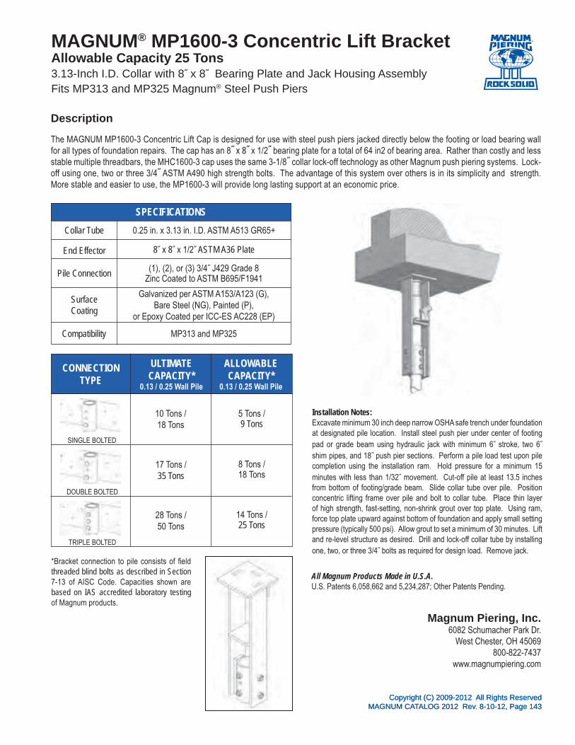
Copyright (C) 2009-2012 All Rights ReservedMAGNUM CATALOG 2012 Rev. 8-10-12, Page 143
All Magnum Products Made in U.S.A.U.S. Patents 6,058,662 and 5,234,287; Other Patents Pending.
Magnum Piering, Inc.6082 Schumacher Park Dr.
West Chester, OH 45069800-822-7437
www.magnumpiering.com
Copyright (C) 2009-2012 All Rights ReservedMAGNUM CATALOG 2012 Rev. 8-10-12, Page 143
CONNECTIONTYPE
SPECIFICATIONS
ULTIMATECAPACITY*
0.13 / 0.25 Wall Pile
ALLOWABLE CAPACITY*
0.13 / 0.25 Wall Pile
MAGNUM® MP1600-3 Concentric Lift BracketAllowable Capacity 25 Tons3.13-Inch I.D. Collar with 8˝ x 8˝ Bearing Plate and Jack Housing AssemblyFits MP313 and MP325 Magnum® Steel Push Piers
The MAGNUM MP1600-3 Concentric Lift Cap is designed for use with steel push piers jacked directly below the footing or load bearing wall for all types of foundation repairs. The cap has an 8˝ x 8˝ x 1/2˝ bearing plate for a total of 64 in2 of bearing area. Rather than costly and less stable multiple threadbars, the MHC1600-3 cap uses the same 3-1/8˝ collar lock-off technology as other Magnum push piering systems. Lock-off using one, two or three 3/4˝ ASTM A490 high strength bolts. The advantage of this system over others is in its simplicity and strength. More stable and easier to use, the MP1600-3 will provide long lasting support at an economic price.
Installation Notes:Excavate minimum 30 inch deep narrow OSHA safe trench under foundation at designated pile location. Install steel push pier under center of footing pad or grade beam using hydraulic jack with minimum 6˝ stroke, two 6˝ shim pipes, and 18˝ push pier sections. Perform a pile load test upon pile completion using the installation ram. Hold pressure for a minimum 15 minutes with less than 1/32˝ movement. Cut-off pile at least 13.5 inches from bottom of footing/grade beam. Slide collar tube over pile. Position concentric lifting frame over pile and bolt to collar tube. Place thin layer of high strength, fast-setting, non-shrink grout over top plate. Using ram, force top plate upward against bottom of foundation and apply small setting pressure (typically 500 psi). Allow grout to set a minimum of 30 minutes. Lift and re-level structure as desired. Drill and lock-off collar tube by installing one, two, or three 3/4˝ bolts as required for design load. Remove jack.
Description
(1), (2), or (3) 3/4˝ J429 Grade 8Zinc Coated to ASTM B695/F1941
Collar Tube 0.25 in. x 3.13 in. I.D. ASTM A513 GR65+
End Effector
Pile Connection
SurfaceCoating
Galvanized per ASTM A153/A123 (G), Bare Steel (NG), Painted (P),
or Epoxy Coated per ICC-ES AC228 (EP)
Compatibility MP313 and MP325
8˝ x 8˝ x 1/2˝ ASTM A36 Plate
10 Tons /18 Tons
5 Tons /9 Tons
17 Tons /35 Tons
8 Tons /18 Tons
28 Tons /50 Tons
14 Tons /25 Tons
SINGLE BOLTED
DOUBLE BOLTED
*Bracket connection to pile consists of field threaded blind bolts as described in Section 7-13 of AISC Code. Capacities shown are based on IAS accredited laboratory testing of Magnum products.
TRIPLE BOLTED

®
All Magnum Products Made in U.S.A.U.S. Patents 6,058,662 and 5,234,287; Other Patents Pending.
Magnum Piering, Inc.6082 Schumacher Park Dr.
West Chester, OH 45069800-822-7437
www.magnumpiering.com
Copyright (C) 2009-2012 All Rights ReservedMAGNUM CATALOG 2012 Rev. 8-10-12, Page 144
SPECIFICATIONS
MAGNUM® MSA50-MP325 AdapterAllowable Capacity 17.5 Tons3˝ x 1/4˝ Wall Adapter Collar Converts Square Shaft to RoundFits MS150 Magnum® Helical Pilesand Converts to MP325 Magnum® Steel Push Piers
The Magnum MSA150-MP325 Adapter slides over the MS150B helical pile shaft and adapts to the MP325 push pier. The adapter allows MS150B helical piles to be used with Magnum's line of standard 3" collar tube brackets such as the MP1001-3, MP1002-3, MP1005-3, and MP1027-3. Use of this adapter with these brackets also enables the use of Magnum push pier rams for lifting, pre-loading, and lock-off. The bracket is designed in accordance with ICC-ES document AC358 as well as IBC, ACI, and AISC codes.
Installation Notes:Install the MS150B helical pile to the correct depth and torque. If necessary, cut-off the pile to an elevation several inches above the planned bracket location as needed for lifting. Slide the MSA150-MP325 Adapter over the MS150B shaft until it rests firmly on the internal welded block. Mount the appropriate Magnum foundation bracket. If necessary add additional push pier extensions for large lifts.
Description
Collar Tube 0.25 in. x 3.00 in. O.D. ASTM A513 GR65+
Pile Connection
Capacity
Surface Coating
Galvanized per ASTM A153/A123 (G) or Standard Magnum Blue Paint (P)
Compatibility MS150B and MP325
Slip Connection with Internal Welded Block
35 kips Ultimate, 17.5 kips Allowable (Compression Only)
Example with MP1002 Example with MP1001
Example with MP1005 Example with MP1027

®
All Magnum Products Made in U.S.A.U.S. Patents 6,058,662 and 5,234,287; Other Patents Pending.
Magnum Piering, Inc.6082 Schumacher Park Dr.
West Chester, OH 45069800-822-7437
www.magnumpiering.com
Copyright (C) 2009-2012 All Rights ReservedMAGNUM CATALOG 2012 Rev. 8-10-12, Page 145
SPECIFICATIONS
MAGNUM® MSA175-MP325 AdapterAllowable Capacity 27.5 Tons 3˝ x 1/4˝ Wall Adapter Collar Converts Square Shaft to RoundFits MS175B Magnum® Helical Pilesand Converts to MP325 Magnum® Steel Push Piers
The Magnum MSA175-MP325 Adapter slides over the MS175B helical pile shaft and adapts to the MP325 push pier. The adapter allows MS175B helical piles to be used with Magnum's line of standard 3" collar tube brackets such as the MP1001-3, MP1002-3, MP1005-3, and MP1027-3. Use of this adapter with these brackets also enables the use of Magnum push pier rams for lifting, pre-loading, and lock-off. The bracket is designed in accordance with ICC-ES document AC358 as well as IBC, ACI, and AISC codes.
Installation Notes:Install the MS175B helical pile to the correct depth and torque. If necessary, cut-off the pile to an elevation several inches above the planned bracket location as needed for lifting. Slide the MSA175-MP325 Adapter over the MS175B shaft until it rests firmly on the internal welded block. Mount the appropriate Magnum foundation bracket. If necessary add additional push pier extensions for large lifts.
Description
Collar Tube 0.25 in. x 3.00 in. O.D. ASTM A513 GR65+
Pile Connection
Capacity
Surface Coating
Galvanized per ASTM A153/A123 (G) or Standard Magnum Blue Paint (P)
Compatibility MS175B and MP325
Slip Connection with Internal Welded Block
55 kips Ultimate, 27.5 kips Allowable (Compression Only)
Example with MP1002 Example with MP1001
Example with MP1005 Example with MP1027

®
Copyright (C) 2009-2012 All Rights ReservedMAGNUM CATALOG 2012 Rev. 8-10-12, Page 147
MA
GN
UM
PIERIN
G, IN
C.s e c t i o n 6
PUSH PIERS & JACKED PILES

Copyright (C) 2009-2012 All Rights ReservedMAGNUM CATALOG 2012 Rev. 8-10-12, Page 148
Shaft Diameter (2
)=1.75˝, (3)=3.0˝, (4
)=4.5˝
Magnum Push Pier (MP)
(G) Galvanized, (NG) Non-Galvanized, or (E
P) Epoxy Powder Coated
Design Wall Thickness (.13˝, .2
˝, .25˝, .3
0˝, .31˝, .3
6˝, .37˝, .4
6˝)
Length (10˝, 18˝, 3
6˝)Ex
plan
atio
n:
The
Mag
num
Pus
h Pi
er p
rodu
ct n
umbe
r abo
ve M
P313
-36G
is fo
r a P
ush
Pier
sec
tion
with
3.0
0˝ d
iam
eter
sha
ft by
36˝
long
, and
the
surfa
ce p
repa
ratio
n is
Gal
vani
zed.
Not
e: S
ee “M
agnu
m P
ierin
g Pu
sh P
ier S
peci
ficat
ions
” tab
le o
n ne
xt p
age
for d
etai
led
info
rmat
ion.
Spe
cific
atio
n in
form
atio
n is
als
o av
aila
ble
at w
ww
.mag
num
pier
ing.
com
Mag
num
Pie
ring,
Inc.
ISO
900
1:20
08C
ertifi
ed
Mag
num
® S
teel
Pus
h P
ier
Pro
duct
Num
ber
Spe
cific
atio
n Le
gend
G36
-13
3M
PPA
RT N
O.
®

Copyright (C) 2009-2012 All Rights ReservedMAGNUM CATALOG 2012 Rev. 8-10-12, Page 149
Mag
num
®
Pus
h P
iers
Sys
tem
Rat
ings
& S
peci
ficat
ions
Des
crip
tion
Sha
ftD
esig
nW
all
Gau
ge(in
)
Sha
ftO
.D.
(in)
Str
uctu
ral C
apac
ity*
(Com
pres
sion
)R
am S
peci
ficat
ions
Max
imum
Test
Load
**(t
ons)
Max
imum
Allo
wab
le
Load
from
Tes
tw
/ F.S
. = 1
.5(t
ons)
Sur
face
Coa
ting
Sta
ndar
dS
ectio
nLe
ngth
s(in
.)U
ltim
ate
(ton
s)A
llow
able
(ton
s)
Pist
onA
rea
(in2 )
Max
imum
Test
Pre
ssur
e(p
si)
MP
212
1.75
˝ Dia
m. x
0.1
2˝ W
all P
ush
Pie
r0.
121.
758
43.
144,
000
64
G, N
G, E
P18
, 36
MP
313
3.00
˝ Dia
m. x
0.1
3˝ W
all P
ush
Pie
r0.
125
3.00
2211
8.30
4,00
017
11G
, NG
, EP
18, 3
6
MP
325
3.00
˝ Dia
m. x
0.2
5˝ W
all P
ush
Pie
r0.
253.
0055
288.
307,
500
3121
G, N
G, E
P18
, 36
MP
413
4.50
˝ Dia
m. x
0.1
3˝ W
all P
ush
Pie
r0.
134.
5040
208.
307,
500
3121
G, N
G, E
P18
, 36
MP
419
4.50
˝ Dia
m. x
0.1
9˝ W
all P
ush
Pie
r0.
188
4.50
6834
8.30
7,50
031
21G
, NG
, EP
18, 3
6
MP
425
4.50
˝ Dia
m. x
0.2
5˝ W
all P
ush
Pie
r0.
254.
5096
4815
.90
7,50
060
40G
, NG
, EP
18, 3
6
MP
431
4.50
˝ Dia
m. x
0.3
1˝ W
all P
ush
Pie
r0.
314.
5012
261
15.9
07,
500
6040
G, N
G, E
P18
, 36
MP
213-
S1.
75˝ D
iam
. x 0
.12˝
Wal
l Sta
rter
0.12
1.75
84
3.00
4,00
06
7G
, NG
, EP
9, 1
8
MP
313-
S3.
00˝ D
iam
. x 0
.13˝
Wal
l Sta
rter
0.12
53.
0022
118.
304,
000
1711
G, N
G, E
P10
, 18
MP
325-
S3.
00˝ D
iam
. x 0
.25˝
Wal
l Sta
rter
0.25
3.00
5528
8.30
7,50
031
21G
, NG
, EP
10, 1
8
MP
413-
S4.
50˝ D
iam
. x 0
.13˝
Wal
l Sta
rter
0.13
4.50
4020
8.30
7,50
031
21G
, NG
, EP
10, 1
8
MP
419-
S4.
50˝ D
iam
. x 0
.19˝
Wal
l Sta
rter
0.18
84.
5068
348.
307,
500
3121
G, N
G, E
P10
, 18
MP
425-
S4.
50˝ D
iam
. x 0
.25˝
Wal
l Sta
rter
0.31
4.50
9648
15.9
07,
500
6040
G, N
G, E
P10
, 18
MP
431-
S4.
50˝ D
iam
. x 0
.31˝
Wal
l Sta
rter
0.31
4.50
122
6115
.90
7,50
060
40G
, NG
, EP
10, 1
8
*Not
e 1
Stru
ctur
al c
apac
ity is
the
theo
retic
al b
uckl
ing
stre
ngth
of t
he s
haft
in fi
rm s
oils
with
fixe
d he
ad c
ondi
tions
(60
in u
nbra
ced
leng
th, K
=0.6
5). T
he c
alcu
latio
n ta
kes
into
acc
ount
cor
rosi
on p
er
ICC
-ES
AC35
8 an
d re
pres
ents
the
capa
city
afte
r cor
rosi
on h
as o
ccur
red.
Buc
klin
g ca
paci
ty w
ill be
less
in s
oft s
oils
, whe
n an
y pa
rt of
the
shaf
t is
stan
ding
uns
uppo
rted
in a
ir, w
ater
or fl
uid
soils
, or i
f hea
d co
nditi
ons
diffe
r.
**N
ote
2 M
axim
um te
st lo
ad is
bas
ed o
n m
axim
um ra
m p
ress
ure
times
pis
ton
area
. Ram
pre
ssur
e is
lim
ited
to th
at w
hich
wou
ld b
uckl
e th
e pi
le o
r the
max
imum
saf
e op
erat
ing
pres
sure
of t
he s
yste
m,
whi
chev
er is
less
. The
stre
ngth
of t
he p
ush
pier
sys
tem
may
be
gove
rned
by
the
brac
ket,
conn
ectio
n of
the
brac
ket t
o th
e pi
er, o
r con
nect
ion
of th
e br
acke
t to
the
stru
ctur
e. A
ll pu
sh p
iers
sho
uld
be lo
ad te
sted
to 1
.5 ti
mes
the
desi
red
desi
gn/w
orki
ng lo
ad.
Surf
ace
Coa
tings
G
= H
ot-D
ip Z
inc
Gal
vani
zed
per A
STM
A12
3/A1
53, N
G =
Bar
e St
eel,
EP =
Epo
xy P
owde
r Coa
ted
per I
CC
-ES
AC22
8
Not
es a
nd S
peci
ficat
ions
Al
l Mag
num
pro
duct
s ar
e m
anuf
actu
red
usin
g AS
TM A
513
Gra
de 6
5 ks
i min
imum
yie
ld s
treng
th s
truct
ural
tubi
ng. A
s M
agnu
m is
com
mitt
ed to
test
ing
and
impr
ovin
g pr
oduc
ts,
thes
e sp
ecifi
catio
ns a
re s
ubje
ct to
cha
nge.
Add
ition
al p
rodu
ct s
peci
ficat
ions
are
ava
ilabl
e at
ww
w.m
agnu
mpi
erin
g.co
m a
nd u
pon
requ
est.
Mag
num
® P
ieri
ngP
ush
Pie
r S
peci
ficat
ions

Copyright (C) 2009-2012 All Rights ReservedMAGNUM CATALOG 2012 Rev. 8-10-12, Page 150
Mag
num
®
Fric
tion
Lead
s
Syst
em R
atin
gs &
Spe
cific
atio
ns
Des
crip
tion
Shaf
tD
esig
nW
all G
auge
(in)
Bea
ring
Rin
gO
.D.
(in)
Max
imum
Allo
wab
le L
oad
from
Tes
tw
/ F.
S. =
1.5
(tons
)
Surf
ace
Coa
ting
Leng
th(in
)Sc
hem
atic
MP2
12-F
L2˝
Fric
tion
Lead
for M
P212
Pus
h Pi
er0.
122.
004
G, N
G, E
P3
MP3
13-F
L3.
5˝ F
rictio
n Le
ad fo
r MP3
13 P
ush
Pier
0.12
53.
5011
G, N
G, E
P3
MP3
25-F
L3.
5˝ F
rictio
n Le
ad fo
r MP3
25 P
ush
Pier
0.25
3.50
21G
, NG
, EP
3
MP3
13-F
L55˝
Fric
tion
Lead
for M
P313
Pus
h Pi
er0.
125
5.00
11G
, NG
, EP
3
MP3
25-F
L55˝
Fric
tion
Lead
for M
P325
Pus
h Pi
er0.
255.
0021
G, N
G, E
P3
MP4
19-F
L5˝
Fric
tion
Lead
for M
P419
Pus
h Pi
er0.
188
5.00
21G
, NG
, EP
3
MP4
25-F
L5˝
Fric
tion
Lead
for M
P425
Pus
h Pi
er0.
255.
0040
G, N
G, E
P3
MP4
31-F
L5˝
Fric
tion
Lead
for M
P431
Pus
h Pi
er0.
315.
0040
G, N
G, E
P3
Surf
ace
Coa
tings
G
= H
ot-D
ip Z
inc
Gal
vani
zed
per A
STM
A12
3/A1
53, N
G =
Bar
e St
eel,
EP =
Epo
xy P
owde
r Coa
ted
per I
CC
-ES
AC22
8
Not
es a
nd S
peci
ficat
ions
Al
l Mag
num
pro
duct
s ar
e m
anuf
actu
red
usin
g AS
TM A
513
Gra
de 6
5 ks
i min
imum
yie
ld s
treng
th s
truct
ural
tubi
ng. A
s M
agnu
m is
com
mitt
ed to
test
ing
and
impr
ovin
g pr
oduc
ts, t
hese
spe
cific
atio
ns a
re s
ubje
ct to
cha
nge.
Add
ition
al p
rodu
ct s
peci
ficat
ions
are
ava
ilabl
e at
ww
w.m
agnu
mpi
erin
g.co
m
and
upon
requ
est.
Mag
num
® P
ieri
ngP
ush
Pie
r Fr
icti
on L
ead
Spe
cific
atio
ns

Copyright (C) 2009-2012 All Rights ReservedMAGNUM CATALOG 2012 Rev. 8-10-12, Page 151
0 25 50 75 100 125 150
Galvanized
Epoxy Powder Coated
Bare Steel/Painted
Design Lifespan (yrs)*
Structural capacities and section properties shown in this catalog are based on a design lifespan of 75 years in most soil conditions for bare steel or painted surfaces unless noted otherwise. Design lifespan can be extended 16 years by epoxy powder coating or more than doubled by hot-dip zinc galvanizing to ASTM A123/A153.
*Design lifespan is determined by backcalculating the time required for a corrosion loss thickness of 50 mils using the rates of corrosion per ICC-ES Document AC358 Guidelines for Design of Helical Foundation Systems and Devices for moderate to highly corrosive soil conditions. Design lifespan is considerably shorter in conditions indicative of severe pile corrosion. Severe pile corrosion conditions are defined by soil resistivity less than 1,000 ohm-cm, soil pH less than 5.5, soils with high organic content, soil sulfate concentrations greater than 1,000 ppm, soils located in landfills, or soil containing mine waste. Design life also may be shortened for piles, anchors, caps and brackets exposed to atmosphere or in direct electrical contact with reinforcing steel or structural steel.
Alternative methods of corrosion loss calculation are available for varying soil conditions and with different building code authorities as shown in the table below from Perko (2009) Helical Piles: A Practical Guide to Design and Installation. Florida DOT and Canadian Building Codes provide other useful references.
MAGNUM technical support personnel can provide assistance with regard to alternative corrosion loss calculation methods. MAGNUM corrosion engineers should be consulted for severe corrosion conditions, for products exposed to atmosphere, and when product applications require direct contact with reinforcing bars or structural steel.
Magnum® Foundation Products Corrosion and Life Expectancy
®

Magnum Piering, Inc.6082 Schumacher Park Dr.
West Chester, OH 45069800-822-7437
www.magnumpiering.comAll Magnum Products Made in U.S.A.
U.S. Patents 6,058,662 and 5,234,287; Other Patents Pending.Copyright (C) 2009-2012 All Rights Reserved
MAGNUM CATALOG 2012 Rev. 8-10-12, Page 152
SPECIFICATIONS
STRUCTURAL CAPACITY IN COMPRESSION*
CAPACITY FROM LOAD TEST**
MAGNUM® MP212 Push Pier4 Tons Allowable Capacity in CompressionHigh-Strength 1.75˝ Diameter, 0.12˝ Wall, Round-ShaftPush Piers with Male-Female Slip Connectors
Magnum® MP212 push piers have a structural capacity in compression of 8 tons ultimate and 4 tons working. Push piers do not have tensile capacity unless the sections are welded together or a reinforcing steel bar and grout is placed in the pile casing. Sections couple together with male-female slip connectors. High strength steel offers increased buckling resistance compared to others. A friction reduction collar can be added to the pile to increase penetration depth. Sections are available in bare steel, epoxy powder coated, and galvanized. Galvanized coating extends average life expectancy to over 100 years even in highly corrosive environments. Custom lengths are available upon request. See Magnum® Technical Manual for additional information.
*Note 1: Structural capacity is based on buckling strength of shaft in firm soils with pinned head conditions after 75 years corrosion for bare steel per ICC-ES AC358. Push piers shall be installed to appropriate depth into suitable bearing stratum as determined by geotechnical engineer or local practice. For tension capacity, push pier sections must be welded together or a reinforcing steel bar and grout must be placed in the pile.
**Note 2: Push pier capacity is determined by load test using Magnum installation rams or lifting kit. All push piers shall be load tested to 1.5 times the desired working load. Test load is limited by maximum safe operating ram pressure or buckling capacity of shaft, whichever is less.
Description
SHAFT HSS 1.75˝ x 0.12˝ wallASTM A513 Grade 65 KSI, or Equiv.
I
Ag
COATINGHot-Dip Galvanized (G),
Bare Steel (NG),or Epoxy Powder Coated (EP)
STANDARDRAM
3.14 in2 Piston Area, 7,500 Maximum P.S.I.(4,000 Max. P.S.I. Installation Pressure)
SCOUPLING
New= 0.21 in4, Corroded= 0.12 in4
New= 0.61 in2, Corroded= 0.36 in2
New= 0.23 in3, Corroded= 0.14 in3
Inner 0.12˝ Sleeve
8 Tons Ultimate
4 Tons Allowable
6 Tons Maximum Test Load
4 Tons Allowable from Test (F.S.=1.5)

Magnum Piering, Inc.6082 Schumacher Park Dr.
West Chester, OH 45069800-822-7437
www.magnumpiering.comAll Magnum Products Made in U.S.A.
U.S. Patents 6,058,662 and 5,234,287; Other Patents Pending.Copyright (C) 2009-2012 All Rights Reserved
MAGNUM CATALOG 2012 Rev. 8-10-12, Page 153
SPECIFICATIONS
STRUCTURAL CAPACITY IN COMPRESSION*
CAPACITY FROM LOAD TEST**
MAGNUM® MP313 Push Pier11 Tons Allowable Capacity in CompressionHigh-Strength 3.00˝ Diameter, 0.13˝ Wall, Round-ShaftPush Piers with Male-Female Slip Connectors
Magnum® MP313 push piers have a structural capacity in compression of 22 tons ultimate and 11 tons working. Push piers do not have tensile capacity unless the sections are welded together or a reinforcing steel bar and grout is placed in the pile casing. Sections couple together with male-female slip connectors. High strength steel offers increased buckling resistance compared to others. A friction reduction collar can be added to the pile to increase penetration depth. Sections are available in bare steel, epoxy powder coated, and galvanized. Galvanized coating extends average life expectancy to over 100 years even in highly corrosive environments. Custom lengths are available upon request. See Magnum® Technical Manual for additional information.
*Note 1: Structural capacity is based on buckling strength of shaft in firm soils with pinned head conditions after 75 years corrosion for bare steel per ICC-ES AC358. Push piers shall be installed to appropriate depth into suitable bearing stratum as determined by geotechnical engineer or local practice. For tension capacity, push pier sections must be welded together or a reinforcing steel bar and grout must be placed in the pile.
**Note 2: Push pier capacity is determined by load test using Magnum installation rams or lifting kit. All push piers shall be load tested to 1.5 times the desired working load. Test load is limited by maximum safe operating ram pressure or buckling capacity of shaft, whichever is less.
Description
SHAFT HSS 3.00˝ x 0.13˝ WallASTM A513 Grade 65 KSI, or Equiv.
I
Ag
COATINGHot-Dip Galvanized (G),
Bare Steel (NG),or Epoxy Powder Coated (EP)
STANDARDRAM
8.30 in2 Piston Area, 7,500 Maximum P.S.I.(4,000 Max. P.S.I. Installation Pressure)
SCOUPLING
New= 1.17 in4, Corroded= 0.70 in4
New= 1.13 in2, Corroded= 0.68 in2
New= 0.78 in3, Corroded= 0.48 in3
Inner 0.125˝ Sleeve
22 Tons Ultimate
11 Tons Allowable
17 Tons Maximum Test Load
11 Tons Allowable from Test (F.S.=1.5)

Magnum Piering, Inc.6082 Schumacher Park Dr.
West Chester, OH 45069800-822-7437
www.magnumpiering.comAll Magnum Products Made in U.S.A.
U.S. Patents 6,058,662 and 5,234,287; Other Patents Pending.Copyright (C) 2009-2012 All Rights Reserved
MAGNUM CATALOG 2012 Rev. 8-10-12, Page 154
SPECIFICATIONS
STRUCTURAL CAPACITY IN COMPRESSION*
CAPACITY FROM LOAD TEST**
MAGNUM® MP325 Push Pier21 Tons Allowable Capacity in CompressionHigh-Strength 3.00˝ Diameter, 0.25˝ Wall, Round-ShaftPush Piers with Male-Female Slip Connectors
Magnum® MP325 push piers have a structural capacity in compression of 55 tons ultimate and 28 tons working. Push piers do not have tensile capacity unless the sections are welded together or a reinforcing steel bar and grout is placed in the pile casing. Sections couple together with male-female slip connectors. High strength steel offers increased buckling resistance compared to others. A friction reduction collar can be added to the pile to increase penetration depth. Sections are available in bare steel, epoxy powder coated, and galvanized. Galvanized coating extends average life expectancy to over 100 years even in highly corrosive environments. Custom lengths are available upon request. See Magnum® Technical Manual for additional information.
*Note 1: Structural capacity is based on buckling strength of shaft in firm soils with pinned head conditions after 75 years corrosion for bare steel per ICC-ES AC358. Push piers shall be installed to appropriate depth into suitable bearing stratum as determined by geotechnical engineer or local practice. For tension capacity, push pier sections must be welded together or a reinforcing steel bar and grout must be placed in the pile.
**Note 2: Push pier capacity is determined by load test using Magnum installation rams or lifting kit. All push piers shall be load tested to 1.5 times the desired working load. Test load is limited by maximum safe operating ram pressure or buckling capacity of shaft, whichever is less.
Description
SHAFT HSS 3.00˝ x 0.25˝ WallASTM A513 Grade 65 KSI, or Equiv.
I
Ag
COATINGHot-Dip Galvanized (G),
Bare Steel (NG),or Epoxy Powder Coated (EP)
STANDARDRAM
8.30 in2 Piston Area, 7,500 Maximum P.S.I.
SCOUPLING
New= 2.06 in4, Corroded= 1.64 in4
New= 2.16 in2, Corroded= 1.73 in2
New= 1.37 in3, Corroded= 1.11 in3
Inner 0.25˝ Sleeve
55 Tons Ultimate
28 Tons Allowable
31 Tons Maximum Test Load
21 Tons Allowable from Test (F.S.=1.5)

Magnum Piering, Inc.6082 Schumacher Park Dr.
West Chester, OH 45069800-822-7437
www.magnumpiering.comAll Magnum Products Made in U.S.A.
U.S. Patents 6,058,662 and 5,234,287; Other Patents Pending.Copyright (C) 2009-2012 All Rights Reserved
MAGNUM CATALOG 2012 Rev. 8-10-12, Page 155
SPECIFICATIONS
STRUCTURAL CAPACITY IN COMPRESSION*
CAPACITY FROM LOAD TEST**
MAGNUM® MP413 Push Pier21 Ton Allowable Capacity in CompressionHigh-Strength 4.50˝ Diameter, 0.13˝ Wall, Round-ShaftPush Piers with Male-Female Slip Connectors
Magnum® MP413 push piers have 40 tons ultimate capacity and 20 tons working capacity in compression. Push piers do not have tensile capacity unless the sections are welded together or a reinforcing steel bar and grout is placed in the pile casing. Sections couple together with male-female slip connectors. Round shafts offer increased lateral and buckling resistance compared to solid square shafts. Galvanized coating extends average life expectancy to over 100 years for most soil conditions. Custom lengths and blade configurations are available upon request. See Magnum® Technical Manual for additional information.
*Note 1: Structural capacity is based on buckling strength of shaft in firm soils with pinned head conditions after 75 years corrosion for bare steel per ICC-ES AC358. Push piers shall be installed to appropriate depth into suitable bearing stratum as determined by geotechnical engineer or local practice. For tension capacity, push pier sections must be welded together or a reinforcing steel bar and grout must be placed in the pile.
**Note 2: Push pier capacity is determined by load test using Magnum installation rams or lifting kit. All push piers shall be load tested to 1.5 times the desired working load. Test load is limited by maximum safe operating ram pressure or buckling capacity of shaft, whichever is less.
Description
SHAFT HSS 4.50˝ x 0.13˝ WallASTM A450 65 KSI, or Equiv.
I
Ag
COATINGHot-Dip Galvanized (G),
Bare Steel (NG),or Epoxy Powder Coated (EP)
STANDARDRAM
8.30 in2 Piston Area, 7,500 MaximumP.S.I.
SCOUPLING
New= 4.26 in4, Corroded= 2.63 in4
New= 1.78 in2, Corroded= 1.10 in2
New= 1.90 in3, Corroded= 1.18 in3
Inner 0.125˝ Sleeve
40 Tons Ultimate Capacity
20 Tons Allowable Capacity
31 Tons Maximum Test Load
21 Tons Allowable from Test (F.S.=1.5)

Magnum Piering, Inc.6082 Schumacher Park Dr.
West Chester, OH 45069800-822-7437
www.magnumpiering.comAll Magnum Products Made in U.S.A.
U.S. Patents 6,058,662 and 5,234,287; Other Patents Pending.Copyright (C) 2009-2012 All Rights Reserved
MAGNUM CATALOG 2012 Rev. 8-10-12, Page 156
SPECIFICATIONS
STRUCTURAL CAPACITY IN COMPRESSION*
CAPACITY FROM LOAD TEST**
MAGNUM® MP419 Push Pier21 Tons Allowable Capacity in CompressionHigh-Strength 4.50˝ Diameter, 0.19˝ Wall, Round-ShaftPush Piers with Male-Female Slip Connectors
Magnum® MP419 push piers have a structural capacity in compression of 68 tons ultimate and 34 tons working. Push piers do not have tensile capacity unless the sections are welded together or a reinforcing steel bar and grout is placed in the pile casing. Sections couple together with male-female slip connectors. High strength steel offers increased buckling resistance compared to others. A friction reduction collar can be added to the pile to increase penetration depth. Sections are available in bare steel, epoxy powder coated, and galvanized. Galvanized coating extends average life expectancy to over 100 years even in highly corrosive environments. Custom lengths are available upon request. See Magnum® Technical Manual for additional information.
*Note 1: Structural capacity is based on buckling strength of shaft in firm soils with pinned head conditions after 75 years corrosion for bare steel per ICC-ES AC358. Push piers shall be installed to appropriate depth into suitable bearing stratum as determined by geotechnical engineer or local practice. For tension capacity, push pier sections must be welded together or a reinforcing steel bar and grout must be placed in the pile.
**Note 2: Push pier capacity is determined by load test using Magnum installation rams or lifting kit. All push piers shall be load tested to 1.5 times the desired working load. Test load is limited by maximum safe operating ram pressure or buckling capacity of shaft, whichever is less.
Description
SHAFT HSS 4.50˝ x 0.19˝ WallASTM A513 Grade 65 KSI, or Equiv.
I
Ag
COATINGHot-Dip Galvanized (G),
Bare Steel (NG),or Epoxy Powder Coated (EP)
STANDARDRAM
8.30 in2 Piston Area, 7,500 Maximum P.S.I.
SCOUPLING
New= 5.99 in4, Corroded= 4.41 in4
New= 2.57 in4, Corroded= 1.90 in2
New= 2.66 in3, Corroded= 1.98 in3
Inner 0.19˝ Sleeve
68 Tons Ultimate
34 Tons Allowable
31 Tons Maximum Test Load
21 Tons Allowable from Test (F.S.=1.5)

Magnum Piering, Inc.6082 Schumacher Park Dr.
West Chester, OH 45069800-822-7437
www.magnumpiering.comAll Magnum Products Made in U.S.A.
U.S. Patents 6,058,662 and 5,234,287; Other Patents Pending.Copyright (C) 2009-2012 All Rights Reserved
MAGNUM CATALOG 2012 Rev. 8-10-12, Page 157
SPECIFICATIONS
STRUCTURAL CAPACITY IN COMPRESSION*
CAPACITY FROM LOAD TEST**
MAGNUM® MP425 Push Pier40 Tons Allowable Capacity in CompressionHigh-Strength 4.50˝ Diameter, 0.25˝ Wall, Round-ShaftPush Piers with Male-Female Slip Connectors
Magnum® MP425 push piers have a structural capacity in compression of 96 tons ultimate and 48 tons working. Push piers do not have tensile capacity unless the sections are welded together or a reinforcing steel bar and grout is placed in the pile casing. Sections couple together with male-female slip connectors. High strength steel offers increased buckling resistance compared to others. A friction reduction collar can be added to the pile to increase penetration depth. Sections are available in bare steel, epoxy powder coated, and galvanized. Galvanized coating extends average life expectancy to over 100 years even in highly corrosive environments. Custom lengths are available upon request. See Magnum® Technical Manual for additional information.
*Note 1: Structural capacity is based on buckling strength of shaft in firm soils with pinned head conditions after 75 years corrosion for bare steel per ICC-ES AC358. Structural capacity is based on buckling strength of shaft in firm soils with fixed head conditions. Push piers shall be installed to appropriate depth into suitable bearing stratum as determined by geotechnical engineer or local practice. For tension capacity, push pier sections must be welded together or a reinforcing steel bar and grout must be placed in the pile.
**Note 2: Push pier capacity is determined by load test using Magnum installation rams or lifting kit. All push piers shall be load tested to 1.5 times the desired working load. Test load is limited by maximum safe operating ram pressure or buckling capacity of shaft, whichever is less.
Description
SHAFT HSS 4.50˝ x 0.25˝ WallASTM A513 Grade 65 KSI, or Equiv.
I
Ag
COATINGHot-Dip Galvanized (G),
Bare Steel (NG),or Epoxy Powder Coated (EP)
STANDARDRAM
15.9 in2 Piston Area,7,500 Maximum P.S.I.
SCOUPLING
New= 7.56 in4, Corroded= 6.05 in4
New= 3.34 in2, Corroded= 2.67 in2
New= 3.36 in3, Corroded= 2.72 in3
Inner 0.25˝ Sleeve
96 Tons Ultimate
48 Tons Allowable
60 Tons Maximum Test Load
40 Tons Allowable from Test (F.S.=1.5)

Magnum Piering, Inc.6082 Schumacher Park Dr.
West Chester, OH 45069800-822-7437
www.magnumpiering.comAll Magnum Steel & Products Made in U.S.A.
U.S. Patents 6,058,662 and 5,234,287; Other Patents Pending.Copyright (C) 2009-2012 All Rights Reserved
MAGNUM CATALOG 2012 Rev. 3-15-12, Page 158
SPECIFICATIONS
STRUCTURAL CAPACITY IN COMPRESSION*
CAPACITY FROM LOAD TEST**
MAGNUM® MP431 Push Pier40 Tons Allowable Capacity in CompressionHigh-Strength 4.50˝ Diameter, 0.31˝ Wall, Round-ShaftPush Piers with Male-Female Slip Connectors
Magnum® MP431 push piers have a structural capacity in compression of 122 tons ultimate and 61 tons working. Push piers do not have tensile capacity unless the sections are welded together or a reinforcing steel bar and grout is placed in the pile casing. Sections couple together with male-female slip connectors. High strength steel offers increased buckling resistance compared to others. A friction reduction collar can be added to the pile to increase penetration depth. Sections are available in bare steel, epoxy powder coated, and galvanized. Galvanized coating extends average life expectancy to over 100 years even in highly corrosive environments. Custom lengths are available upon request. See Magnum® Technical Manual for additional information.
*Note 1: Structural capacity is based on buckling strength of shaft in firm soils with pinned head conditions after 75 years corrosion for bare steel per ICC-ES AC358. Push piers shall be installed to appropriate depth into suitable bearing stratum as determined by geotechnical engineer or local practice. For tension capacity, push pier sections must be welded together or a reinforcing steel bar and grout must be placed in the pile.
**Note 2: Push pier capacity is determined by load test using Magnum installation rams or lifting kit. All push piers shall be load tested to 1.5 times the desired working load. Test load is limited by maximum safe operating ram pressure or buckling capacity of shaft, whichever is less.
Description
SHAFT HSS 4.50˝ x 0.31˝ WallASTM A513 Grade 65 KSI, or Equiv.
I
Ag
COATINGHot-Dip Galvanized (G),
Bare Steel (NG),or Epoxy Powder Coated (EP)
STANDARDRAM
15.9 in2 Piston Area7,500 Maximum P.S.I.
SCOUPLING
New= 9.00 in4, Corroded= 7.55 in4
New= 4.08 in2, Corroded= 3.43 in2
New= 4.00 in3, Corroded= 3.39 in3
Inner 0.25˝ Sleeve
122 Tons Ultimate
61 Tons Allowable
60 Tons Maximum Test Load
40 Tons Allowable from Test (F.S.=1.5)

Magnum Piering, Inc.6082 Schumacher Park Dr.
West Chester, OH 45069800-822-7437
www.magnumpiering.comAll Magnum Products Made in U.S.A.
U.S. Patents 6,058,662 and 5,234,287; Other Patents Pending.Copyright (C) 2009-2012 All Rights Reserved
MAGNUM CATALOG 2012 Rev. 8-10-12, Page 159
SPECIFICATIONS
STRUCTURAL CAPACITY IN COMPRESSION*
SHAFT HSS 4.98˝ x 11˝ Long ASTM A513 Grade 65 KSI, or Equiv.
I
Ag
COATINGHot-Dip Galvanized (G),
Bare Steel (NG),or Epoxy Powder Coated (EP)
5.5˝ O.D. x 0.25˝ Wall (Sold Separately)
S
JACKED PILESHAFT
New= 10.42 in4, Corroded= 8.33 in4
New= 3.71 in2, Corroded= 2.97 in2
New= 4.18 in3, Corroded= 3.38 in3
100 Tons Ultimate
50 Tons Allowable
MAGNUM® MJP55C Jacked Pile Coupling50 Tons Allowable Capacity in CompressionHigh-Strength Inner-Sleeve CouplingFits 5.50˝ Diameter x 0.25˝ Wall Steel Jacked Piles
Push piers and jacked piles are essentially the same type of foundation. In this catalog, the term push piers is used for more slender piles that are generally installed from the side of an existing foundation. Whereas, the term jacked piles is used for larger diameter piles that are installed from jacking pits excavated directly below the center of an existing foundation. Push piers generally do not require special excavation shoring; they promote improved worker safety, and the installation is generally faster. Jacked piles do require special excavation shoring and are slower to install. However, jacked piles exert less rotational stresses on an existing foundation and sometimes can be installed to higher capacity. Special precautions are required for excavation shoring and worker safety.
*Note 1: Structural capacity is based on capacity of welded center ring after 75 years corrosion for bare steel. Jacked piles shall be installed to appropriate depth into suitable bearing stratum as determined by geotechnical engineer or local practice. For tension capacity, push pier sections must be welded together or a reinforcing steel bar and grout must be placed in the pile.
Note 2: Jacked pile capacity is determined by load test using a hydraulic ram centered on the foundation. All jacked piles shall be load tested to 1.5 times the desired working load. Test load is limited by maximum safe operating ram pressure of the ram, available dead load of the existing foundation, or structural capacity of the foundation, whichever is less.
Description

Magnum Piering, Inc.6082 Schumacher Park Dr.
West Chester, OH 45069800-822-7437
www.magnumpiering.comAll Magnum Products Made in U.S.A.
U.S. Patents 6,058,662 and 5,234,287; Other Patents Pending.Copyright (C) 2009-2012 All Rights Reserved
MAGNUM CATALOG 2012 Rev. 8-10-12, Page 160
SPECIFICATIONS
STRUCTURAL CAPACITY IN COMPRESSION*
SHAFT HSS 6.5˝ O.D. x 13˝ LongASTM A513 Grade 65 KSI, or Equiv.
I
Ag
COATINGHot-Dip Galvanized (G),
Bare Steel (NG),or Epoxy Powder Coated (EP)
7.0˝ O.D. x 0.23˝ Wall (Sold Separately)
S
JACKED PILESHAFT
New= 24.01 in4, Corroded= 19.21 in4
New= 4.91 in2, Corroded= 3.93 in2
New= 7.39 in3, Corroded= 5.96 in3
100 Tons Ultimate
50 Tons Allowable
MAGNUM® MJP70C Jacked Pile Coupling50 Tons Allowable Capacity in CompressionHigh-Strength Inner-Sleeve CouplingFits 7.0˝ Diameter x 0.23˝ Wall Steel Jacked Piles
Description
*Note 1: Structural capacity is based on capacity of welded center ring after 75 years corrosion for bare steel. Jacked piles shall be installed to appropriate depth into suitable bearing stratum as determined by geotechnical engineer or local practice. For tension capacity, push pier sections must be welded together or a reinforcing steel bar and grout must be placed in the pile.
Note 2: Jacked pile capacity is determined by load test using a hydraulic ram centered on the foundation. All jacked piles shall be load tested to 1.5 times the desired working load. Test load is limited by maximum safe operating ram pressure of the ram, available dead load of the existing foundation, or structural capacity of the foundation, whichever is less.
Push piers and jacked piles are essentially the same type of foundation. In this catalog, the term push piers is used for more slender piles that are generally installed from the side of an existing foundation. Whereas, the term jacked piles is used for larger diameter piles that are installed from jacking pits excavated directly below the center of an existing foundation. Push piers generally do not require special excavation shoring; they promote improved worker safety, and the installation is generally faster. Jacked piles do require special excavation shoring and are slower to install. However, jacked piles exert less rotational stresses on an existing foundation and sometimes can be installed to higher capacity. Special precautions are required for excavation shoring and worker safety.

Magnum Piering, Inc.6082 Schumacher Park Dr.
West Chester, OH 45069800-822-7437
www.magnumpiering.comAll Magnum Products Made in U.S.A.
U.S. Patents 6,058,662 and 5,234,287; Other Patents Pending.Copyright (C) 2009-2012 All Rights Reserved
MAGNUM CATALOG 2012 Rev. 8-10-12, Page 161
SPECIFICATIONS
STRUCTURAL CAPACITY IN COMPRESSION*
SHAFT HSS 8.0˝ O.D. x 19.25˝ LongASTM A513 Grade 65 KSI, or Equiv.
I
Ag
COATINGHot-Dip Galvanized (G),
Bare Steel (NG),or Epoxy Powder Coated (EP)
8.63˝ O.D. x 0.22˝ Wall (Sold Separately)
S
JACKED PILESHAFT
New= 45.75 in4, Corroded= 36.62 in4
New= 6.09 in2, Corroded= 4.87 in2
New= 11.44 in3, Corroded= 9.21 in3
100 Tons Ultimate
75 Tons Allowable
MAGNUM® MJP86C Jacked Pile Coupling 75 Tons Allowable Capacity in CompressionHigh-Strength Inner-Sleeve CouplingFits 8.63˝ Diameter x 0.22˝ Wall Steel Jacked Piles
Description
*Note 1: Structural capacity is based on capacity of welded center ring after 75 years corrosion for bare steel. Jacked piles shall be installed to appropriate depth into suitable bearing stratum as determined by geotechnical engineer or local practice. For tension capacity, push pier sections must be welded together or a reinforcing steel bar and grout must be placed in the pile.
Note 2: Jacked pile capacity is determined by load test using a hydraulic ram centered on the foundation. All jacked piles shall be load tested to 1.5 times the desired working load. Test load is limited by maximum safe operating ram pressure of the ram, available dead load of the existing foundation, or structural capacity of the foundation, whichever is less.
Push piers and jacked piles are essentially the same type of foundation. In this catalog, the term push piers is used for more slender piles that are generally installed from the side of an existing foundation. Whereas, the term jacked piles is used for larger diameter piles that are installed from jacking pits excavated directly below the center of an existing foundation. Push piers generally do not require special excavation shoring; they promote improved worker safety, and the installation is generally faster. Jacked piles do require special excavation shoring and are slower to install. However, jacked piles exert less rotational stresses on an existing foundation and sometimes can be installed to higher capacity. Special precautions are required for excavation shoring and worker safety.

Magnum Piering, Inc.6082 Schumacher Park Dr.
West Chester, OH 45069800-822-7437
www.magnumpiering.comAll Magnum Products Made in U.S.A.
U.S. Patents 6,058,662 and 5,234,287; Other Patents Pending.Copyright (C) 2009-2012 All Rights Reserved
MAGNUM CATALOG 2012 Rev. 8-10-12, Page 162
SPECIFICATIONS
STRUCTURAL CAPACITY IN COMPRESSION*
SHAFT HSS 10.0˝ O.D. x 23.5˝ Long ASTM A513 Grade 65 KSI, or Equiv.
I
Ag
COATINGHot-Dip Galvanized (G),
Bare Steel (NG),or Epoxy Powder Coated (EP)
10.75˝ O.D. x 0.31˝ Wall (Sold Separately)
S
JACKED PILESHAFT
New= 91.05 in4, Corroded= 72.90 in4
New= 7.66 in2, Corroded= 6.13 in2
New= 18.21 in3, Corroded= 14.65 in3
150 Tons Ultimate
75 Tons Allowable
MAGNUM® MJP100C Jacked Pile Coupling75 Tons Allowable Capacity in CompressionHigh-Strength Inner-Sleeve CouplingFits 10.75˝ Diameter x 0.31˝ Wall Steel Jacked Piles
Description
*Note 1: Structural capacity is based on capacity of welded center ring after 75 years corrosion for bare steel. Jacked piles shall be installed to appropriate depth into suitable bearing stratum as determined by geotechnical engineer or local practice. For tension capacity, push pier sections must be welded together or a reinforcing steel bar and grout must be placed in the pile.
Note 2: Jacked pile capacity is determined by load test using a hydraulic ram centered on the foundation. All jacked piles shall be load tested to 1.5 times the desired working load. Test load is limited by maximum safe operating ram pressure of the ram, available dead load of the existing foundation, or structural capacity of the foundation, whichever is less.
Push piers and jacked piles are essentially the same type of foundation. In this catalog, the term push piers is used for more slender piles that are generally installed from the side of an existing foundation. Whereas, the term jacked piles is used for larger diameter piles that are installed from jacking pits excavated directly below the center of an existing foundation. Push piers generally do not require special excavation shoring; they promote improved worker safety, and the installation is generally faster. Jacked piles do require special excavation shoring and are slower to install. However, jacked piles exert less rotational stresses on an existing foundation and sometimes can be installed to higher capacity. Special precautions are required for excavation shoring and worker safety.

Magnum Piering, Inc.6082 Schumacher Park Dr.
West Chester, OH 45069800-822-7437
www.magnumpiering.comAll Magnum Products Made in U.S.A.
U.S. Patents 6,058,662 and 5,234,287; Other Patents Pending.Copyright (C) 2009-2012 All Rights Reserved
MAGNUM CATALOG 2012 Rev. 8-10-12, Page 163
SPECIFICATIONS
STRUCTURAL CAPACITY IN COMPRESSION*
SHAFT HSS 6.5˝ O.D. x 11.1˝ LongASTM A513 Grade 65 KSI, or Equiv.
I
Ag
COATINGHot-Dip Galvanized (G),
Bare Steel (NG),or Epoxy Powder Coated (EP)
7.0˝ O.D. x 0.23˝ Wall to 5.5˝ O.D. x 0.26˝ Wall
(Sold Separately)
S
JACKED PILESHAFT
New= 24.01 in4, Corroded= 19.21 in4
New= 4.91 in2, Corroded= 3.93 in2
New= 7.39 in3, Corroded= 5.96 in3
100 Tons Ultimate
50 Tons Allowable
MAGNUM® MJP55C Jacked Pile Coupling50 Tons Allowable Capacity in CompressionHigh-Strength Transition Coupling Transitions 7˝ Diam. x 0.23˝ Wall and 5.5˝ Diam. x 0.26˝ Wall Steel Jacked Piles
Description
*Note 1: Structural capacity is based on capacity of welded center ring after 75 years corrosion for bare steel. Jacked piles shall be installed to appropriate depth into suitable bearing stratum as determined by geotechnical engineer or local practice. For tension capacity, push pier sections must be welded together or a reinforcing steel bar and grout must be placed in the pile.
Note 2: Jacked pile capacity is determined by load test using a hydraulic ram centered on the foundation. All jacked piles shall be load tested to 1.5 times the desired working load. Test load is limited by maximum safe operating ram pressure of the ram, available dead load of the existing foundation, or structural capacity of the foundation, whichever is less.
Push piers and jacked piles are essentially the same type of foundation. In this catalog, the term push piers is used for more slender piles that are generally installed from the side of an existing foundation. Whereas, the term jacked piles is used for larger diameter piles that are installed from jacking pits excavated directly below the center of an existing foundation. Push piers generally do not require special excavation shoring; they promote improved worker safety, and the installation is generally faster. Jacked piles do require special excavation shoring and are slower to install. However, jacked piles exert less rotational stresses on an existing foundation and sometimes can be installed to higher capacity. Special precautions are required for excavation shoring and worker safety.

®
Copyright (C) 2009-2012 All Rights ReservedMAGNUM CATALOG 2012 Rev. 8-10-12, Page 165
MA
GN
UM
PIERIN
G, IN
C.
MA
GN
UM
PIERIN
G, IN
C.
s e c t i o n 7
PUSH PIERS RAMS & ACCESSORIES

Magnum Piering, Inc.6082 Schumacher Park Dr.
West Chester, OH 45069800-822-7437
www.magnumpiering.com
All Magnum Products Made in U.S.A.U.S. Patents 6,058,662 and 5,234,287; Other Patents Pending. Copyright (C) 2009-2012 All Rights Reserved
MAGNUM CATALOG 2012 Rev. 8-10-12, Page 166
SPECIFICATIONS
35
30
25
20
15
10
5
0
0 1,000 2,000 3,000 4,000 5,000 6,000 7,000 8,000
Ram Area = 8.30 in2
Max
. Pre
ssur
e
Forc
e (T
ons)
Pressure (psi)
Ram Force Calibration
3.25˝ Diam.
2.0˝ Diam.
22˝
7,500 psi
15,00 psi
(1) 3/4˝
2.5˝ Diam. (Fits MP313 & MP325 Shafts)
3/8˝ Diam.
Bore
Piston Rod
Stroke
Max. Pressure
Burst Pressure
Bolts
Nose Adapter
Hydraulic Hose
Note: Magnum’s push piering system is used for stabilization and lifting. Bracket connection to structure, required pier capacity, and pier spacing should be designed by a professional engineer taking into account the thickness, weight, live loads, and punching shear strength of the existing foundation.
MAGNUM® MP6000K Ram Kit31 Ton Maximum Capacity3.25˝ Bore, 22˝ Stroke, 7,500 psi Maximum PressureHydraulic Ram Assembly for MP313 and MP325 Push Pier Shafts
Magnum MP6000 Push Pier Rams are used for installation and load testing Magnum MP313 and MP325 push piers. The ram has an ultimate capacity of 31 tons at maximum pressure. It is used for repair, lifting, and permanent support of existing foundations. Ram height with channels is82.5 inches. The assembly can accommodate push pier columns up to 36˝ long that are coupled together by male-female slip connections. Additional push pier column sections can be added until the pier reaches adequate bearing material and a successful load test is achieved. Ram shoe fits various Magnum foundation brackets. Permanent pier to bracket connection is made with up to three (3) ¾˝ Grade 8 bolts.
Description
Hydraulic Ram
Quick Connectors
Nose Adapter
Aluminum Channels
Ram Shoe

Magnum Piering, Inc.6082 Schumacher Park Dr.
West Chester, OH 45069800-822-7437
www.magnumpiering.com
All Magnum Products Made in U.S.A.U.S. Patents 6,058,662 and 5,234,287; Other Patents Pending. Copyright (C) 2009-2012 All Rights Reserved
MAGNUM CATALOG 2012 Rev. 8-10-12, Page 167
SPECIFICATIONS
35
30
25
20
15
10
5
0
0 1,000 2,000 3,000 4,000 5,000 6,000 7,000 8,000
Ram Area = 8.30 in2
Max
. Pre
ssur
e
Forc
e (T
ons)
Pressure (psi)
Ram Force Calibration
3.25˝ Diam.
2.0˝ Diam.
12˝
7,500 psi
15,00 psi
(1) 3/4˝
2.5˝ Diam. (Fits MP313 & MP325 Shafts)
3/8˝ Diam.
Bore
Piston Rod
Stroke
Max. Pressure
Burst Pressure
Bolts
Nose Adapter
Hydraulic Hose
Note: Magnum’s push piering system is used for stabilization and lifting. Bracket connection to structure, required pier capacity, and pier spacing should be designed by a professional engineer taking into account the thickness, weight, live loads, and punching shear strength of the existing foundation.
MAGNUM® MP6100K Ram Kit31 Ton Maximum Capacity3.25˝ Bore, 12˝ Stroke, 7,500 psi Maximum PressureHydraulic Ram Assembly for MP313 and MP325 Push Pier Shafts
Magnum MP6100 Push Pier Rams are used for installation and load testing Magnum MP313 and MP325 push piers. The ram has an ultimate capacity of 31 tons at maximum pressure. It is used for repair, lifting, and permanent support of existing foundations. Ram height with channels is 52-7/8 inches. The assembly can accommodate push pier columns up to 18˝ long that are coupled together by male-female slip connections. A ditional push pier column sections can be added until the pier reaches adequate bearing material and a successful load test is achieved. Ram shoe fits various Magnum foundation brackets. Permanent pier to bracket connection is made with up to three (3) ¾˝ Grade 8 bolts.
Description
Hydraulic Ram
Quick Connectors
Nose Adapter
Aluminum Channels
Ram Shoe

Magnum Piering, Inc.6082 Schumacher Park Dr.
West Chester, OH 45069800-822-7437
www.magnumpiering.com
All Magnum Products Made in U.S.A.U.S. Patents 6,058,662 and 5,234,287; Other Patents Pending. Copyright (C) 2009-2012 All Rights Reserved
MAGNUM CATALOG 2012 Rev. 8-10-12, Page 168
SPECIFICATIONS
14
12
10
8
6
4
2
0
0 1,000 2,000 3,000 4,000 5,000 6,000 7,000 8,000
Ram Area = 3.14 in2
Max
. Pre
ssur
e
Forc
e (T
ons)
Pressure (psi)
Ram Force Calibration
2.00˝ Diam.
1.25˝ Diam.
22˝
7,500 psi
15,00 psi
(1) 3/4˝
1.75˝ Diam. (Fits MP212 Push Pier Shaft)
3/8˝ Diam.
Bore
Piston Rod
Stroke
Max. Pressure
Burst Pressure
Bolts
Nose Adapter
Hydraulic Hose
Note: Magnum’s push piering system is used for stabilization and lifting. Bracket connection to structure, required pier capacity, and pier spacing should be designed by a professional engineer taking into account the thickness, weight, live loads, and punching shear strength of the existing foundation.
MAGNUM® MP7000K Ram Kit12 Ton Maximum Capacity2.00˝ Bore, 22˝ Stroke, 7,500 psi Maximum PressureHydraulic Ram Assembly for MP212 Push Pier Shaft
Magnum MP7000 Push Pier Rams are used for installation and load testing Magnum MP212 push piers. The ram has an ultimate capacity of 12 tons at maximum pressure. It is used for repair, lifting, and permanent support of existing foundations. Ram height with channels is 76-9/16 inches. The assembly can accommodate push pier columns up to 36˝ long that are coupled together by male-female slip connections. Additional push pier column sections can be added until the pier reaches adequate bearing material and a successful load test is achieved. Ram shoe fits various Magnum foundation brackets. Permanent pier to bracket connection is made with up to three (3) ¾˝ Grade 8 bolts.
Description
Hydraulic Ram
Quick Connectors
Nose Adapter
Aluminum Channels
Ram Shoe

Magnum Piering, Inc.6082 Schumacher Park Dr.
West Chester, OH 45069800-822-7437
www.magnumpiering.com
All Magnum Products Made in U.S.A.U.S. Patents 6,058,662 and 5,234,287; Other Patents Pending. Copyright (C) 2009-2012 All Rights Reserved
MAGNUM CATALOG 2012 Rev. 8-10-12, Page 169
SPECIFICATIONS
14
12
10
8
6
4
2
0
0 1,000 2,000 3,000 4,000 5,000 6,000 7,000 8,000
Ram Area = 3.14 in2
Max
. Pre
ssur
e
Forc
e (T
ons)
Pressure (psi)
Ram Force Calibration
Bore
Piston Rod
Stroke
Max. Pressure
Burst Pressure
Bolts
Nose Adapter
Hydraulic Hose
Note: Magnum’s push piering system is used for stabilization and lifting. Bracket connection to structure, required pier capacity, and pier spacing should be designed by a professional engineer taking into account the thickness, weight, live loads, and punching shear strength of the existing foundation.
MAGNUM® MP7100K Ram Kit12 Ton Maximum Capacity2.00˝ Bore, 12˝ Stroke, 7,500 psi Maximum PressureHydraulic Ram Assembly for MP212 Push Pier Shaft
Magnum MP7100 Push Pier Rams are used for installation and load testing Magnum MP212 push piers. The ram has an ultimate capacity of 12 tons at maximum pressure. It is used for repair, lifting, and permanent support of existing foundations. Ram height with channels is 52-7/8 inches. The assembly can accommodate push pier columns up to 18˝ long that are coupled together by male-female slip connections. Additional push pier column sections can be added until the pier reaches adequate bearing material and a successful load test is achieved. Ram shoe fits variousMagnum foundation brackets. Permanent pier to bracket connection is made with up to three (3) ¾˝ Grade 8 bolts.
Description
2.00˝ Diam.
1.25˝ Diam.
12˝
7,500 psi
15,00 psi
(1) 3/4˝
1.75˝ Diam. (Fits MP212 Push Pier Shaft)
3/8˝ Diam.
Hydraulic Ram
Quick Connectors
Nose Adapter
Aluminum Channels
Ram Shoe

®
Copyright (C) 2009-2012 All Rights ReservedMAGNUM CATALOG 2012 Rev. 8-10-12, Page 171
MA
GN
UM
PIERIN
G, IN
C.
s e c t i o n 8
SLABJACK PIERING SYSTEM

Copyright (C) 2009-2012 All Rights ReservedMAGNUM CATALOG 2012 Rev. 8-10-12, Page 172
Mag
num
®
Slab
jack
Pie
r
Syst
em R
atin
gs &
Spe
cific
atio
ns
Des
crip
tion
Shaf
tD
esig
nW
all
Gau
ge(in
)
Shaf
tO
.D.
(in)
Stru
ctur
al C
apac
ity*
(Com
pres
sion
)R
am S
peci
ficat
ions
Max
imum
Test
Load
**(to
ns)
Max
imum
Allo
wab
le
Load
from
Tes
tw
/ F.S
. = 1
.5(to
ns)
Surf
ace
Coa
ting
Stan
dard
Sect
ion
Leng
ths
(in.)
Ulti
mat
e(to
ns)
Allo
wab
le(to
ns)
Pist
onA
rea
(in2 )
Max
imum
Test
Pres
sure
(psi
)
MP1
131.
31˝ D
iam
. x 0
.12˝
Wal
l Sla
bjac
k Pi
er0.
121.
315.
12.
63.
142,
500
3.9
2.6
G, N
G, E
P18
, 36
MP1
13-S
1.31
˝ Dia
m. x
0.1
2˝ W
all S
tarte
r0.
121.
315.
12.
63.
142,
500
3.9
2.6
G, N
G, E
P18
MP1
13-F
LFr
ictio
n Le
ad fo
r MP1
13 S
labj
ack
Pier
0.2
1.75
5.1
2.6
3.14
2,50
03.
92.
6G
, NG
, EP
2
MP2
121.
75˝ D
iam
. x 0
.12˝
Wal
l Sla
bjac
k Pi
er0.
121.
758
4.0
3.14
3,82
26.
04.
0G
, NG
, EP
18, 3
6
MP2
12-S
1.75
˝ Dia
m. x
0.1
2˝ W
all S
tarte
r0.
121.
758
4.0
3.14
3,82
26.
04.
0G
, NG
, EP
18
MP2
12-F
LFr
ictio
n Le
ad fo
r MP2
12 S
labj
ack
Pier
0.2
2.00
84.
03.
143,
822
6.0
4.0
G, N
G, E
P2
*Not
e 1
Stru
ctur
al c
apac
ity is
the
theo
retic
al b
uckl
ing
stre
ngth
of t
he s
haft
in fi
rm s
oils
with
pin
ned
head
con
ditio
ns w
ithou
t acc
ount
ing
for c
orro
sion
(tem
pora
ry s
hort-
term
app
licat
ions
).
Buck
ling
capa
city
will
be le
ss in
sof
t soi
ls, w
hen
any
part
of th
e sh
aft i
s st
andi
ng u
nsup
porte
d in
air,
wat
er o
r flui
d so
ils, o
r if h
ead
cond
ition
s di
ffer.
**N
ote
2 M
axim
um te
st lo
ad is
bas
ed o
n m
axim
um ra
m p
ress
ure
times
pis
ton
area
. Ram
pre
ssur
e is
lim
ited
to th
at w
hich
wou
ld b
uckl
e th
e pi
le o
r the
max
imum
saf
e op
erat
ing
pres
sure
of t
he s
yste
m,
whi
chev
er is
less
. The
stre
ngth
of t
he p
ush
pier
sys
tem
may
be
gove
rned
by
the
brac
ket,
conn
ectio
n of
the
brac
ket t
o th
e pi
er, o
r con
nect
ion
of th
e br
acke
t to
the
stru
ctur
e. A
ll sl
abja
ck p
iers
sh
ould
be
load
test
ed to
1.5
tim
es th
e de
sire
d de
sign
/wor
king
load
. Sla
bjac
k pi
ers
are
for t
empo
rary
sup
port
only
unl
ess
conn
ectio
n to
sla
b is
des
igne
d by
a re
gist
ered
pro
fess
iona
l.
Surf
ace
Coa
tings
G
= H
ot-D
ip Z
inc
Gal
vani
zed
per A
STM
A12
3/A1
53, N
G =
Bar
e St
eel,
EP =
Epo
xy P
owde
r Coa
ted
per I
CC
-ES
AC22
8
Not
es a
nd S
peci
ficat
ions
Al
l Mag
num
pro
duct
s ar
e m
anuf
actu
red
usin
g AS
TM A
513
Gra
de 6
5 ks
i min
imum
yie
ld s
treng
th s
truct
ural
tubi
ng. A
s M
agnu
m is
com
mitt
ed to
test
ing
and
impr
ovin
g pr
oduc
ts,
thes
e sp
ecifi
catio
ns a
re s
ubje
ct to
cha
nge.
Add
ition
al p
rodu
ct s
peci
ficat
ions
are
ava
ilabl
e at
ww
w.m
agnu
mpi
erin
g.co
m a
nd u
pon
requ
est.
Mag
num
® P
ieri
ngS
labj
ack
Pie
r S
peci
ficat
ions

Magnum Piering, Inc.6082 Schumacher Park Dr.
West Chester, OH 45069800-822-7437
www.magnumpiering.comAll Magnum Products Made in U.S.A.
U.S. Patents 6,058,662 and 5,234,287; Other Patents Pending.Copyright (C) 2009-2012 All Rights Reserved
MAGNUM CATALOG 2012 Rev. 8-10-12, Page 173
SPECIFICATIONS
STRUCTURAL CAPACITY IN COMPRESSION*
CAPACITY FROM LOAD TEST**
MAGNUM® MP113 Slabjack Pier2.6 Tons Allowable Capacity in Compression High-Strength 1.31˝ Diameter, 0.12˝ Wall, Round-Shaft Slabjack Pier with Male-Female Slip Connectors
Magnum® MP113 slabjack piers have a structural capacity in compression of 5.1 tons ultimate and 2.6 tons working. Slabjack piers do not have tensile capacity unless the sections are welded together or a reinforcing steel bar and grout is placed in the pile casing. Sections couple together with male-female slip connectors. High strength steel offers increased buckling resistance compared to others. A friction reduction collar can be added to the pile to increase penetration depth. Sections are available in bare steel, epoxy powder coated, and galvanized. Galvanized coating extends average life expectancy to over 100 years even in highly corrosive environments. Custom lengths are available upon request. See Magnum® Technical Manual for additional information.
*Note 1: Structural capacity is based on buckling strength of shaft in firm soils with pinned head conditions without corrosion (temporary short- term applications). Push piers shall be installed to appropriate depth into suitable bearing stratum as determined by geotechnical engineer or local practice. For tension capacity, push pier sections must be welded together or a reinforcing steel bar and grout must be placed in the pile.
**Note 2: Push pier capacity is determined by load test using Magnum installation rams or lifting kit. All push piers shall be load tested to 1.5 times the desired working load. Test load is limited by maximum safe operating ram pressure or buckling capacity of shaft, whichever is less.
Description
SHAFT HSS 1.31˝ x 0.12˝ wallASTM A513 Grade 65 KSI, or Equiv.
I
Ag
COATINGHot-Dip Galvanized (G),
Bare Steel (NG),or Epoxy Powder Coated (EP)
STANDARDRAM
3.14 in2 Piston Area, 5,000 Maximum P.S.I. (2,500 Max. P.S.I. Installation Pressure)
SCOUPLING
New= 0.08 in4
New= 0.45 in2
New= 0.12 in3
Inner 0.12˝ Sleeve
5.1 Tons Ultimate
2.6 Tons Allowable
3.9 Tons Maximum Test Load
2.6 Tons Allowable from Test (F.S.=1.5)

Magnum Piering, Inc.6082 Schumacher Park Dr.
West Chester, OH 45069800-822-7437
www.magnumpiering.com
All Magnum Products Made in U.S.A.U.S. Patents 6,058,662 and 5,234,287; Other Patents Pending. Copyright (C) 2009-2012 All Rights Reserved
MAGNUM CATALOG 2012 Rev. 8-10-12, Page 174
SPECIFICATIONS
10
9
8
7
6
5
4
3
2
00 1,000
Ram Area = 3.14 in2
Max
. Pre
ssur
e
Forc
e (T
ons)
Pressure (psi)
Ram Force Calibration
1
2,000 3,000 4,000 5,000 6,000
Bore
Piston Rod
Stroke
Max. Pressure
Burst Pressure
Bolts
Nose Adapter
Hydraulic Hose
Note: Magnum’s slabjack piering system is rated for temporary lifting only. Permanent slab support, pier to slab connection, required pier capacity, and pier spacing should be designed by a professional engineer taking into account the thickness, weight, live loads, and punching shear strength of the slab.
MAGNUM® MP6500K Slabjack Ram Kit8 Ton Maximum Capacity2.00˝ Bore, 20˝ Stroke, 5,000 psi Maximum PressureHydraulic Ram Assembly for MP113 Slabjack Pier Shaft
Magnum MP6500 Slabjack Rams are used for lifting and temporary support of slabs-on-grade and other light structures. The ram has an ultimate lifting capacity of 8 tons at maximum pressure. It is used for precision lifting applications in combination with grout injection for longer term support. Ram and tripod height is 66.16˝. The assembly can accommodate push pier columns up to 36˝ long that are coupled together by male female slip connections. Additional push pier column sections can be added until the pier reaches adequate bearing material and a successful load test is achieved. Base plate is 15˝ equilateral triangle with (9) bolt hole pattern. Temporary pier to slab connection is made with roll pin.
Description
2.00˝ Diam.
1.25˝ Diam.
20˝
5,000 psi
12,00 psi
(9) ½˝ x 4.5˝ Titen HD or Equiv.
1.0˝ Diam. (Fits MP113 Push Pier Shaft)
3/8˝ Diam.
Hydraulic Ram
Quick Connectors
Nose Adapter
Tripod Stand
Base Plate

Magnum Piering, Inc.6082 Schumacher Park Dr.
West Chester, OH 45069800-822-7437
www.magnumpiering.comAll Magnum Products Made in U.S.A.
U.S. Patents 6,058,662 and 5,234,287; Other Patents Pending.Copyright (C) 2009-2012 All Rights Reserved
MAGNUM CATALOG 2012 Rev. 8-10-12, Page 175
SPECIFICATIONS
STRUCTURAL CAPACITY IN COMPRESSION*
CAPACITY FROM LOAD TEST**
MAGNUM® MP212 Slabjack Pier 4 Tons Allowable Capacity in Compression High-Strength 1.75˝ Diameter, 0.12˝ Wall, Round-Shaft Slabjack Pier with Male-Female Slip Connectors
Magnum® MP212 slabjack piers have a structural capacity in compression of 8 tons ultimate and 4 tons working. Slabjack piers do not have tensile capacity unless the sections are welded together or a reinforcing steel bar and grout is placed in the pile casing. Sections couple together with male-female slip connectors. High strength steel offers increased buckling resistance compared to others. A friction reduction collar can be added to the pile to increase penetration depth. Sections are available in bare steel, epoxy powder coated, and galvanized. Galvanized coating extends average life expectancy to over 100 years even in highly corrosive environments. Custom lengths are available upon request. See Magnum® Technical Manual for additional information.
*Note 1: Structural capacity is based on buckling strength of shaft in firm soils with pinned head conditions without corrosion (temporary short- term applications). Push piers shall be installed to appropriate depth into suitable bearing stratum as determined by geotechnical engineer or local practice. For tension capacity, push pier sections must be welded together or a reinforcing steel bar and grout must be placed in the pile.
**Note 2: Push pier capacity is determined by load test using Magnum installation rams or lifting kit. All push piers shall be load tested to 1.5 times the desired working load. Test load is limited by maximum safe operating ram pressure or buckling capacity of shaft, whichever is less.
Description
SHAFT HSS 1.75˝ x 0.12˝ wallASTM A513 Grade 65 KSI, or Equiv.
I
Ag
COATINGHot-Dip Galvanized (G),
Bare Steel (NG),or Epoxy Powder Coated (EP)
STANDARDRAM
RAM 3.14 in2 Piston Area, 7,500 Maximum P.S.I. (4,000 Max. P.S.I. Installation Pressure)
SCOUPLING
New= 0.21 in4
New= 0.61 in2
New= 0.23 in3
Inner 0.12˝ Sleeve
8 Tons Ultimate
4 Tons Allowable
6 Tons Maximum Test Load
4 Tons Allowable from Test (F.S.=1.5)

Magnum Piering, Inc.6082 Schumacher Park Dr.
West Chester, OH 45069800-822-7437
www.magnumpiering.comAll Magnum Products Made in U.S.A.
U.S. Patents 6,058,662 and 5,234,287; Other Patents Pending.Copyright (C) 2009-2012 All Rights Reserved
MAGNUM CATALOG 2012 Rev. 8-10-12, Page 176
SPECIFICATIONS
14
12
10
8
6
4
2
0
0 1,000 2,000 3,000 4,000 5,000 6,000 7,000 8,000
Ram Area = 3.14 in2
Max
. Pre
ssur
e
Forc
e (T
ons)
Pressure (psi)
Ram Force Calibration
Bore
Piston Rod
Stroke
Max. Pressure
Burst Pressure
Bolts
Nose Adapter
Hydraulic Hose
Note: Magnum’s slabjack piering system is rated for temporary lifting only. Permanent slab support, pier to slab connection, required pier capacity, and pier spacing should be designed by a professional engineer taking into account the thickness, weight, live loads, and punching shear strength of the slab.
MAGNUM® MP7500K Slabjack Ram Kit8 Ton Maximum Capacity2.00˝ Bore, 20˝ Stroke, 5,000 psi Maximum PressureHydraulic Ram Assembly for MP212 Slabjack Pier Shaft
Magnum MP7500 Slabjack Rams are used for lifting and temporary support of slabs-on-grade and other light structures. The ram has an ultimate lifting capacity of 8 tons at maximum pressure. It is used for precision lifting applications in combination with grout injection for longer term support. Ram and stand height is 66.16˝. The assembly can accommodate push pier columns up to 36˝ long that are coupled together by male-female slip connections. Additional push pier column sections can be added until the pier reaches adequate bearing material and a successful load test is achieved. Base plate consists of two 6˝ x 12˝ rectangles with (10) bolt hole pattern. Pier to slab connection, if needed, is by non-shrink grout.
Description
2.00˝ Diam.
1.25˝ Diam.
22˝
7,500 psi
15,000 psi
(10) ½˝ x 4.5˝ Titen HD or Equiv.
1.75˝ Diam. (Fits MP212 Push Pier Shaft)
3/8˝ Diam.
Hydraulic Ram
Carrying Handle
Nose Adapter
Aluminum Stand
Base Plate
®
Copyright (C) 2009-2012 All Rights ReservedMAGNUM CATALOG 2012 Rev. 8-10-12, Page 177
MA
GN
UM
PIERIN
G, IN
C.s e c t i o n 9
MICROPILE & THREADBAR BRACKETS

Copyright (C) 2009-2012 All Rights ReservedMAGNUM CATALOG 2012 Rev. 8-10-12, Page 178
Mag
num
®
Mic
ropi
leB
rack
ets
Nam
e
Fits
Pile
Dia
m.
(in)
No.
Bol
ts /
Thru
Hol
es
Bol
t H
ole
Dia
m.
(in)
Stru
ctur
al C
apac
ity*
Des
crip
tion
Surf
ace
Coa
ting*
*Sc
hem
atic
Ulti
mat
e(to
ns)
Com
p / T
ens
Allo
wab
le(to
ns)
Com
p / T
ens
MP1
009-
30M
icro
pile
Ang
leBr
acke
t3.
003
3/4
50 /
2225
/ 11
8˝ x
6˝ x
21˝
Gus
sete
d An
gle
w/ 8
bol
t hol
esG
, P
MP1
009-
35M
icro
pile
Ang
leBr
acke
t3.
503
3/4
50 /
2225
/ 11
8˝ x
6˝ x
21˝
Gus
sete
d An
gle
w/ 8
bol
t hol
esG
, P
MP1
009-
40M
icro
pile
Ang
leBr
acke
t4.
003
3/4
50 /
2225
/ 11
8˝ x
6˝ x
21˝
Gus
sete
d An
gle
w/ 8
bol
t hol
esG
, P
MP1
009-
45M
icro
pile
Ang
leBr
acke
t4.
503
3/4
50 /
2225
/ 11
8˝ x
6˝ x
21˝
Gus
sete
d An
gle
w/ 8
bol
t hol
esG
, P
MP1
018-
30M
icro
pile
Pla
teBr
acke
t3.
003
3/4
50 /
5025
/ 25
8˝ x
27˝
x 3
/8˝ P
late
w/ 1
8 bo
lt ho
les
G, P
MP1
018-
35M
icro
pile
Pla
teBr
acke
t3.
503
3/4
50 /
5025
/ 25
8˝ x
27˝
x 3
/8˝ P
late
w/ 1
8 bo
lt ho
les
G, P
MP1
018-
40M
icro
pile
Pla
teBr
acke
t4.
003
3/4
50 /
5025
/ 25
8˝ x
27˝
x 3
/8˝ P
late
w/ 1
8 bo
lt ho
les
G, P
MP1
018-
45M
icro
pile
Pla
teBr
acke
t4.
503
3/4
50 /
5025
/ 25
8˝ x
27˝
x 3
/8˝ P
late
w/ 1
8 bo
lt ho
les
G, P
Sys
tem
Rat
ings
& S
peci
ficat
ions
Show
n he
re w
ith M
P101
0dr
ill a
rms
(sol
d se
para
tely
)
Avai
labl
e w
ith M
P102
0 dr
illar
ms
(sol
d se
para
tely
)
*Not
e 1
All M
agnu
m p
rodu
cts
are
man
ufac
ture
d us
ing
min
imum
A51
3 65
ksi
min
imum
yie
ld s
treng
th s
truct
ural
tubi
ng, o
r bet
ter,
for t
he c
olla
r and
AST
M A
36 p
late
ste
el, o
r bet
ter,
for t
he b
earin
g pl
ates
. As
Mag
num
is c
omm
itted
to te
stin
g an
d im
prov
ing
prod
ucts
, the
se s
peci
ficat
ions
are
sub
ject
to c
hang
e. A
dditi
onal
pro
duct
spe
cific
atio
ns m
ay b
e av
aila
ble
at w
ww
.mag
num
pier
ing.
com
from
Mag
num
’s te
chni
cal s
uppo
rt pr
ofes
sion
als
upon
requ
est.
Stru
ctur
al c
apac
ity o
f bra
cket
and
mic
ropi
le s
yste
m m
ay b
e lim
ited
by th
e ca
paci
ty o
f the
mic
ropi
le a
nd th
e st
ruct
ure
to w
hich
the
brac
ket i
s co
nnec
ted.
Cap
acity
of t
he m
icro
pile
and
stru
ctur
e sh
all b
e de
term
ined
by
an e
ngin
eer.
**N
ote
2 G
=hot
dip
gal
vani
zed
per A
STM
A15
3/A1
23 a
s ap
prop
riate
, P=M
agnu
m b
lue
pain
t
Mag
num
® P
ieri
ngM
icro
pile
Bra
cket
Spe
cific
atio
ns

Magnum Piering, Inc.6082 Schumacher Park Dr.
West Chester, OH 45069800-822-7437
www.magnumpiering.com
All Magnum Products Made in U.S.A.U.S. Patents 6,058,662 and 5,234,287; Other Patents Pending.
Copyright (C) 2009-2012 All Rights ReservedMAGNUM CATALOG 2012 Rev. 8-10-12, Page 179
SPECIFICATIONS
CONNECTIONTYPE
ULTIMATECAPACITY
0.13 / 0.25 CasingWall Thickness
ALLOWABLE CAPACITY
0.13 / 0.25 CasingWall Thickness
Magnum Piering® MP1009Micropile Bracket26 Tons Maximum Allowable Capacity8˝ x 6˝ x 21˝ x 3/8˝ Angle with 8 – 9/16˝ Bolt HolesFits 3˝, 3.5˝, 4˝, & 4.5˝ O.D. Steel Micropile Casings
The Magnum MP1009 micropile bracket has 54 tons maximum ultimate capacity, 26 tons working capacity in compression and tension. The bracket consists of any one of 4 different sized collar tube with three ¾˝ threaded bolt holes for connection to steel micropile casings. The bracket has 8 holes for attachment to existing concrete using concrete anchors. The bracket is designed in accordance with IBC, ACI, and AISC codes. Design and detailing of the connection to the structure varies by project and is the responsibility of registered design professional including maximum concrete span, pier spacing, concrete shear, and concrete bearing.
Installation Note:Apply a layer of quick-set chemical grout to the angle and attach to the foundation using (8) 1/2˝ concrete anchors. After grout sets, attach drill support arms and mount drill. Drill the micropile to the specified depth. Install desired reinforcing steel bar, grout, and a 6’ minimum section of casing at the top of the pile. Slip appropriate collar tube over micropile casing and secure to bracket with 1-1/4˝ bolt supplied. Remove the drill and the drill arms for use on the next micropile. Once the micropile grout has cured, a Magnum ram, or Magnum lifting kit, with the appropriate size drive shoe can be used to lift and re-level the structure if necessary. Lock-off the pile to the bracket with one, two, or three 3/4˝ Grade 8 bolts, or weld.
Description
*Bracket connection to pile consists of field threaded blind bolts as described in Section 7-13 of AISC Code. Capacities shown are based on IAS accredited laboratory testing of Magnum products.
10 Tons /18 Tons
5 Tons /9 Tons
17 Tons /35 Tons
8 Tons /18 Tons
28 Tons /53 Tons
14 Tons /26 Tons
SINGLE BOLTED
DOUBLE BOLTED
TRIPLE BOLTED
(1, 2, or 3) 3/4˝ SAE GR8 / ASTM A480
Collar Tube 0.37 in. x 3˝, 3.5˝, 4˝, or 4.5˝ I.D.ASTM A513 GR65+
Configuration
Pile Connection
SurfaceCoating
Galvanized per ASTM A153/A123 (G),Standard Magnum Blue Paint (P),
or Epoxy Coated per ICC-ES AC228 (EP)
Compatibility 3˝, 3.5˝, 4˝, and 4.5˝ O.D. Steel MicropileCasings
8˝x6˝x21˝x3/8˝ Angle with 8 – 9/16˝ Bolt Holes

Magnum Piering, Inc.6082 Schumacher Park Dr.
West Chester, OH 45069800-822-7437
www.magnumpiering.com
All Magnum Products Made in U.S.A.U.S. Patents 6,058,662 and 5,234,287; Other Patents Pending.
Copyright (C) 2009-2012 All Rights ReservedMAGNUM CATALOG 2012 Rev. 8-10-12, Page 180
SPECIFICATIONS
CONNECTIONTYPE
ULTIMATECAPACITY
0.13 / 0.25 CasingWall Thickness
ALLOWABLE CAPACITY
0.13 / 0.25 CasingWall Thickness
Magnum Piering® MP1018Micropile Bracket26 Tons Maximum Allowable Capacity8˝ x 27˝ x 3/8˝ Plate with 18 – 1/2˝ Bolt HolesFits 3˝, 3.5˝, 4˝, & 4.5˝ O.D. Steel Micropile Casings
The Magnum MP1018 micropile bracket has 54 tons maximum ultimate capacity, 26 tons working capacity in compression and tension. The bracket consists of any one of 4 different sized collar tube with three ¾˝ threaded bolt holes for connection to steel micropile casings. The bracket has 16 holes for attachment to existing concrete using concrete anchors. The bracket is designed in accordance with IBC, ACI, and AISC codes. Design and detailing of the connection to the structure varies by project and is the responsibility of registered design professional including maximum concrete span, pier spacing, concrete shear, and concrete bearing.
Installation Note:Attach bracket plate to the side of foundation using up to (18) 1/2˝ concrete anchors. Red Head, Strong Bolt, or Titan anchors may be used as well as epoxy dowels. Most concrete anchors typically offer 3 kips working load each (see anchor manufacturer for strength information, specific bolt patterns should be checked by an engineer or load tested to at least F.S. = 1.5). Attach drill support arms and mount drill. Drill the micropile to the specified depth. Install desired reinforcing steel bar, grout, and a 6´ minimum section of casing at the top of the pile. Remove drill support arms and slip appropriate collar tube over micropile casing and secure to bracket with pins supplied. Once the micropile grout has cured, a Magnum ram, or Magnum lifting kit, with the appropriate size drive shoe can be used to lift and re-level the structure if necessary. Lock-off the pile to the bracket with one, two, or three 3/4˝ Grade 8 bolts, or weld.
Description
*Bracket connection to pile consists of field threaded blind bolts as described in Section 7-13 of AISC Code. Capacities shown are based on IAS accredited laboratory testing of Magnum products.
10 Tons /18 Tons
5 Tons /9 Tons
17 Tons /35 Tons
8 Tons /18 Tons
28 Tons /53 Tons
14 Tons /26 Tons
SINGLE BOLTED
DOUBLE BOLTED
TRIPLE BOLTED
(1, 2, or 3) 3/4˝ SAE GR8 / ASTM A480
Collar Tube 0.37 in. x 3˝, 3.5˝, 4˝, or 4.5˝ I.D.ASTM A513 GR65+
Configuration
Pile Connection
SurfaceCoating
Galvanized per ASTM A153/A123 (G),Standard Magnum Blue Paint (P),
or Epoxy Coated per ICC-ES AC228 (EP)
Compatibility 3˝, 3.5˝, 4˝, and 4.5˝ O.D. Steel MicropileCasings
8˝x27˝x3/8˝ Plate with 16 – 1/2˝ Bolt Holes

All Magnum Products Made in U.S.A.U.S. Patents 6,058,662 and 5,234,287; Other Patents Pending.
Magnum Piering, Inc.6082 Schumacher Park Dr.
West Chester, OH 45069800-822-7437
www.magnumpiering.com
Copyright (C) 2009-2012 All Rights ReservedMAGNUM CATALOG 2012 Rev. 8-10-12, Page 181
SPECIFICATIONS
Magnum Piering® MP1029 Grout-Guide Micropile Bracket 38 Tons Maximum Allowable Capacity8˝ x 12 ˝ x 24˝ x 1/2˝ Angle with 12 – 11/16˝ Bolt Holes Fits 6˝, 6.5˝, 7˝, & 8.6˝ O.D. Steel Micropile Casings
The Magnum MP1029 micropile bracket has 76 tons maximum ultimate capacity, 38 tons working capacity in compression and 3 tons maximum ultimate capacity, 1.5 tons working capacity in tension. Tension capacity is governed by concrete break-out, the amount of reinforcing in the existing foundation, and the strength of the concrete. The bracket consists of a 12.75˝ diameter guide tube for connection to steel micropile casings. The bracket has 16 holes for attachment to existing concrete using concrete anchors. The bracket is designed in accordance with IBC, ACI, and AISC codes. Design and detailing of the connection to the structure varies by project and is the responsibility of registered design professional including maximum concrete span, pier spacing, concrete shear, and concrete bearing.
Installation Note:Excavate soil in area of bracket. Notch footing (if any) flush with foundation wall. Apply a thin layer of quick-set non-shrink grout to the angle and attach to the foundation using a minimum of (6) 5/8˝ concrete anchors. After grout sets, drill micropile through the center of the guide sleeve. Install desired reinforcing steel bar, grout, and a 6’ minimum section of casing at the top of the micropile. Fill annular space between guide sleeve and micropile casing with high-strength, non-shrink grout.
Fill Annular Space with High-Strength, Non-Shrink Grout
Grout-Guide 12.75˝ Diam. x 0.13˝ Wall (or better) x 36˝ Long ASTM A513 GR65+
Configuration
Pile Connection
SurfaceCoating
Galvanized per ASTM A153/A123 (G),Standard Magnum Blue Paint (P),
or Epoxy Coated per ICC-ES AC228 (EP)
Compatibility 6˝, 6.5˝, 7˝, and 8.6˝ O.D. Steel Micropile Casings
8˝ x 12˝ x 24˝ x 1/2˝ Angle with 12 – 11/16˝ Bolt Holes

Copyright (C) 2009-2012 All Rights ReservedMAGNUM CATALOG 2012 Rev. 8-10-12, Page 182
Expl
anat
ion:
The
Mag
num
All-
Thre
ad B
ar A
cces
sory
pro
duct
num
ber a
bove
MTB
075-
06L2
4LH
G is
for a
gra
de 7
5, a
ll-th
read
bar
with
nom
inal
dia
met
er o
f 3/4
˝. Th
e ba
r is
24˝ l
ong
with
left-
hand
thre
ad. T
he s
urfa
ce re
para
tion
is G
alva
nize
d.
Not
e: S
ee “M
agnu
m A
ll-Th
read
Bar
Acc
esso
ry S
peci
ficat
ions
” tab
le o
n ne
xt p
age
for d
etai
led
info
rmat
ion.
Spe
cific
atio
n in
form
atio
n is
als
o av
aila
ble
at w
ww
.mag
num
pier
ing.
com
Mag
num
Pie
ring,
Inc.
ISO
900
1:20
08C
ertifi
ed
Mag
num
® A
ll-T
hrea
d B
arP
rodu
ct N
umbe
r S
peci
ficat
ion
Lege
nd
Steel Grade, 60 ksi, 75 ksi, 90 ksi, 150 ksi,
Magnum All-Thread Bar
Threadbar Length in Inches (24˝, 60˝, 120˝)
Other Custom Lengths Available
Bar Nominal Diameter Designation, 06=3/4˝, 0
7=7/8˝, 08=1˝,
09=1-1/8˝, 1
0=1-1/4˝, 11=1-3/8˝, 1
4=1-3/4˝, 18=2-1/4˝,
20=2-1/2˝, 2
4=3˝, 28=3-1/2˝
Bar Length
GLH
06-
075
MTB
PART
NO
.L
24
(G) Galvanized, (NG) Non-Galvanized, or (E
P) Epoxy Powder Coated
Thread Direction (Right Hand, Left Hand)
®

Magnum Piering, Inc.6082 Schumacher Park Dr.
West Chester, OH 45069800-822-7437
www.magnumpiering.comAll Magnum Products Made in U.S.A.
U.S. Patents 6,058,662 and 5,234,287; Other Patents Pending.Copyright (C) 2009-2012 All Rights Reserved
MAGNUM CATALOG 2012 Rev. 8-10-12, Page 183
SPECIFICATIONS
DESIGNATIONNOMINAL
DIAMETERGROSS AREA
ULTIMATE STRENGTH
YIELD STRENGTH
NOMINAL WEIGHT
PART NUMBER
06 3/4˝ 0.44 IN2 22 TONS 17 TONS 1.5 PLF MTB075-06LH
07 7/8˝ 0.60 IN2 30 TONS 23 TONS 2.0 PLF MTB075-07LH
08 1˝ 0.79 IN2 40 TONS 30 TONS 2.7 PLF MTB075-08LH
09 1-1/8˝ 1.00 IN2 50 TONS 38 TONS 3.4 PLF MTB075-09LH
10 1-1/4˝ 1.27 IN2 64 TONS 48 TONS 4.3 PLF MTB075-10LH
11 1-3/8˝ 1.56 IN2 78 TONS 59 TONS 5.3 PLF MTB075-11LH
14 1-3/4˝ 2.25 IN2 113 TONS 84 TONS 7.7 PLF MTB075-14RH
18 2-1/4˝ 4.00 IN2 200 TONS 150 TONS 13.6 PLF MTB075-18RH
20 2-1/2˝ 4.91 IN2 246 TONS 184 TONS 16.7 PLF MTB075-20RH
28 3-1/2˝ 9.61 IN2 480 TONS 360 TONS 32.7 PLF MTB075-28RH
Magnum Piering® MTB075 Grade 75 All-Threadbar22 ton to 480 ton Ultimate Capacity75 ksi Yield, 100 ksi Ultimate Strength Continuous Threaded Bar
Grade 75 All-Thread bars have an ultimate capacity from 22 to 480 tons in tension and compression (fully braced conditions only). All-Thread bars can be used in a variety of applications including micropiles, rock anchors, soil nails, and soil anchors for permanent and temporary structures. All-threadbars are typically installed in ground using a fixed or articulated mast microdrill with down-hole or top vibratory hammer. These systems can have advantages over helical piles and push piers in soils with excessive rock, cobble, or debris. They also are useful when penetration into hard to very hard bedrock is required. Ultimate and yield strength shown in specifications below is indicative of the steel structural strength without corrosion. The strength of micropiles, rock anchors, soil nails, and soil anchors in ground may be limited by the soil-grout bond or grout-steel bond. Magnum recommends that all threadbar applications be designed by a licensed professional engineer or architect experienced in the design of these systems. Magnum technical support representatives are available to assist with design of grouted threadbar systems for a multitude of applications.
Description
LH = Left Hand ThreadRH = Right Hand Thread

Copyright (C) 2009-2012 All Rights ReservedMAGNUM CATALOG 2012 Rev. 8-10-12, Page 184
Mag
num
Pie
ring,
Inc.
ISO
900
1:20
08C
ertifi
ed
Mag
num
® A
ll-T
hrea
d B
ar A
cces
sory
Pro
duct
Num
ber
Spe
cific
atio
n Le
gend
®
GLH
06-
075
MTB
PART
NO
.-
HN
Steel Grade, 60 ksi, 75 ksi, 90 ksi, 150 ksi,
Magnum All-Thread Bar
Part Type (HN=Hex Nut, JN=Jam Nut, JN=Hex Nut, SN=Spherical Nut,
HW=Hardened Washer, BW=Bevel Washer, SC=Stop Coupler)
Bar Nominal Diameter Designation, 06=3/4˝, 0
7=7/8˝, 08=1˝,
09=1-1/8˝, 1
0=1-1/4˝, 11=1-3/8˝, 1
4=1-3/4˝, 18=2-1/4˝,
20=2-1/2˝, 2
4=3˝, 28=3-1/2˝
(G) Galvanized, (NG) Non-Galvanized, or (E
P) Epoxy Powder Coated
Thread Direction (Right Hand, Left Hand)
Expl
anat
ion:
The
Mag
num
All-
Thre
ad B
ar A
cces
sory
pro
duct
num
ber a
bove
MTB
075-
06-H
NLH
G is
for a
gra
de 7
5, h
ex n
ut th
at fi
ts a
n al
l-thr
ead
bar w
ith n
omin
al d
iam
eter
of 3
/4˝.
The
nut h
as le
ft-ha
nd th
read
. The
sur
face
repa
ratio
n is
Gal
vani
zed.
Not
e: S
ee “M
agnu
m P
ierin
g Al
l-Thr
ead
Bar A
cces
sory
” tab
le o
n ne
xt p
age
for d
etai
led
info
rmat
ion.
Spe
cific
atio
n in
form
atio
n is
als
o av
aila
ble
at w
ww
.mag
num
pier
ing.
com

Copyright (C) 2009-2012 All Rights ReservedMAGNUM CATALOG 2012 Rev. 8-10-12, Page 185
Mag
num
®
Acc
esso
ries
Des
crip
tion
Fits
Pro
duct
Des
igna
tion
Not
esSu
rfac
e C
oatin
g**
Sche
mat
ic
MTB
075-
06H
NLH
#6 G
R75
Hex
Nut
MD
M6I
S122
4G
Hex
nut
s ar
e ty
pica
lly s
old
with
MH
C10
80 C
aps.
N
uts
show
n he
re a
re
for s
urpl
us o
r re
plac
emen
t par
ts.
G, N
G, E
P
MTB
075-
08H
NLH
#8 G
R75
Hex
Nut
MSC
1080
-150
824,
M
HC
1080
-382
4,
MH
C10
80-3
5824
G, N
G, E
P
MTB
075-
10H
NLH
#10
GR
75 H
ex N
utM
SC10
80-1
7510
24,
MH
C10
80-3
1024
, M
HC
1080
-410
24G
, NG
, EP
MTB
075-
14H
NR
H#1
4 G
R75
Hex
Nut
MH
C10
80-4
1424
G, N
G, E
P
MTB
075-
20H
NR
H#2
0 G
R75
Hex
Nut
MH
C10
80-5
2024
, M
HC
1080
-620
24G
, NG
, EP
MTB
075-
06JN
LH#6
GR
75 J
am N
utM
DM
6IS1
224G
Hex
nut
s ar
e ty
pica
lly s
old
with
MH
C10
80 C
aps.
N
uts
show
n he
re a
re
for s
urpl
us o
r rep
lace
men
t par
ts.
G, N
G, E
P
MTB
075-
08JN
LH#8
GR
75 J
am N
utM
SC10
80-1
5082
4,
MH
C10
80-3
824,
MH
C10
80-3
5824
G, N
G, E
P
MTB
075-
10JN
LH#1
0 G
R75
Jam
Nut
MSC
1080
-175
1024
, M
HC
1080
-310
24,
MH
C10
80-4
1024
G, N
G, E
P
MTB
075-
14JN
RH
#14
GR
75 J
am N
utM
HC
1080
-414
24G
, NG
, EP
MTB
075-
20JN
RH
#20
GR
75 J
am N
utM
HC
1080
-520
24,
MH
C10
80-6
2024
G, N
G, E
P
MTB
075-
06EN
LH#6
Eye
Nut
MD
M6I
S122
4G
Eye
nuts
can
be
used
w
ith M
HC
1080
C
ap to
cre
ate
an
effe
ctiv
e gu
y an
chor
.
G, N
G
MTB
075-
08EN
LH#8
Eye
Nut
MSC
1080
-150
824,
M
HC
1080
-382
4,
MH
C10
80-3
5824
G, N
G
MTB
075-
10EN
LH#1
0 Ey
e N
utM
SC10
80-1
7510
24,
MH
C10
80-3
1024
, M
HC
1080
-410
24G
, NG
MTB
075-
20EN
RH
#20
Eye
Nut
MH
C10
80-5
2024
, M
HC
1080
-620
24G
, NG
Sys
tem
Rat
ings
& S
peci
ficat
ions
Mag
num
® P
ieri
ngT
hrea
dbar
Acc
esso
ries
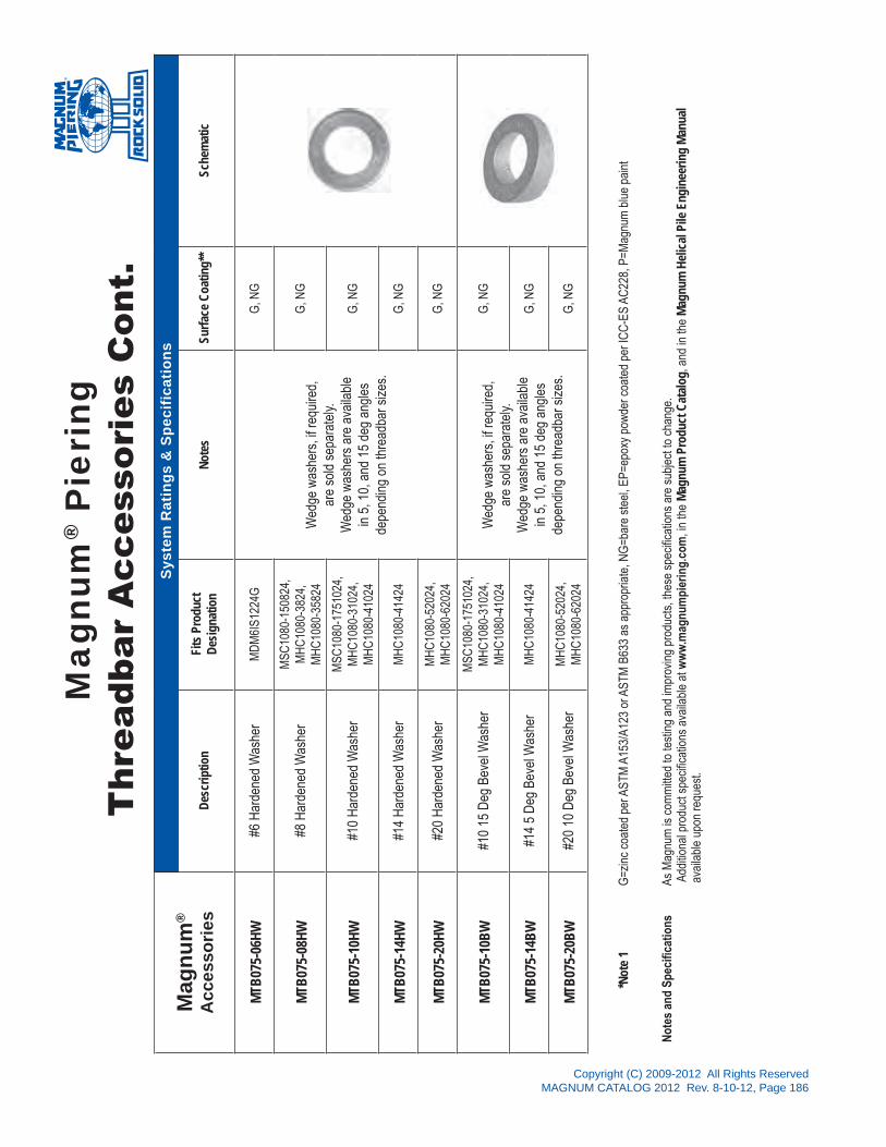
Copyright (C) 2009-2012 All Rights ReservedMAGNUM CATALOG 2012 Rev. 8-10-12, Page 186
Mag
num
®
Acc
esso
ries
Des
crip
tion
Fits
Pro
duct
Des
igna
tion
Not
esSu
rfac
e C
oatin
g**
Sche
mat
ic
MTB
075-
06H
W#6
Har
dene
d W
ashe
rM
DM
6IS1
224G
Wed
ge w
ashe
rs, i
f req
uire
d,
are
sold
sep
arat
ely.
W
edge
was
hers
are
ava
ilabl
e in
5, 1
0, a
nd 1
5 de
g an
gles
de
pend
ing
on th
read
bar s
izes
.
G, N
G
MTB
075-
08H
W#8
Har
dene
d W
ashe
rM
SC10
80-1
5082
4,
MH
C10
80-3
824,
M
HC
1080
-358
24G
, NG
MTB
075-
10H
W#1
0 H
arde
ned
Was
her
MSC
1080
-175
1024
, M
HC
1080
-310
24,
MH
C10
80-4
1024
G, N
G
MTB
075-
14H
W#1
4 H
arde
ned
Was
her
MH
C10
80-4
1424
G, N
G
MTB
075-
20H
W#2
0 H
arde
ned
Was
her
MH
C10
80-5
2024
, M
HC
1080
-620
24G
, NG
MTB
075-
10B
W#1
0 15
Deg
Bev
el W
ashe
rM
SC10
80-1
7510
24,
MH
C10
80-3
1024
, M
HC
1080
-410
24W
edge
was
hers
, if r
equi
red,
ar
e so
ld s
epar
atel
y.
Wed
ge w
ashe
rs a
re a
vaila
ble
in 5
, 10,
and
15
deg
angl
es
depe
ndin
g on
thre
adba
r siz
es.
G, N
G
MTB
075-
14B
W#1
4 5
Deg
Bev
el W
ashe
rM
HC
1080
-414
24G
, NG
MTB
075-
20B
W#2
0 10
Deg
Bev
el W
ashe
rM
HC
1080
-520
24,
MH
C10
80-6
2024
G, N
G
Sys
tem
Rat
ings
& S
peci
ficat
ions
Mag
num
® P
ieri
ngT
hrea
dbar
Acc
esso
ries
Con
t.
*Not
e 1
G
=zin
c co
ated
per
AST
M A
153/
A123
or A
STM
B63
3 as
app
ropr
iate
, NG
=bar
e st
eel,
EP=e
poxy
pow
der c
oate
d pe
r IC
C-E
S AC
228,
P=M
agnu
m b
lue
pain
t
Not
es a
nd S
peci
ficat
ions
As
Mag
num
is c
omm
itted
to te
stin
g an
d im
prov
ing
prod
ucts
, the
se s
peci
ficat
ions
are
sub
ject
to c
hang
e.
Add
ition
al p
rodu
ct s
peci
ficat
ions
ava
ilabl
e at
ww
w.m
agnu
mpi
erin
g.co
m, i
n th
e M
agnu
m P
rodu
ct C
atal
og, a
nd in
the
Mag
num
Hel
ical
Pile
Eng
inee
ring
Man
ual
a
vaila
ble
upon
requ
est.

®
Copyright (C) 2009-2012 All Rights ReservedMAGNUM CATALOG 2012 Rev. 8-10-12, Page 187
MA
GN
UM
PIERIN
G, IN
C.s e c t i o n 1 0
SOLAR PANEL FOUNDATIONS

Copyright (C) 2009-2012 All Rights ReservedMAGNUM CATALOG 2012 Rev. 8-10-12, Page 188
Ex
plan
atio
n:
The
Mag
num
Hel
ical
Sol
ar P
ile p
rodu
ct n
umbe
r abo
ve M
HS4
13P1
0K12
D14
DG
is fo
r a P
ile w
ith 4
.5˝ d
iam
eter
sha
ft, a
0.1
3˝ w
all t
hick
ness
, an
inte
gral
pla
te c
ap, 1
0 ft.
long
with
(2
) 0.3
75˝ D
uall
Cut
ting
Edge
Hel
ices
, 12
and
14 in
ches
in d
iam
eter
, and
the
surfa
ce re
para
tion
is G
alva
nize
d.
Not
e: S
ee “M
agnu
m P
ierin
g H
elic
al S
olar
Pile
Spe
cific
atio
ns” t
able
on
next
pag
e fo
r det
aile
d in
form
atio
n. S
peci
ficat
ion
info
rmat
ion
is a
lso
avai
labl
e at
ww
w.m
agnu
mpi
erin
g.co
m
Mag
num
® H
elic
al S
olar
Pile
Pro
duct
Num
ber
Spe
cific
atio
n Le
gend
Mag
num
Pie
ring,
Inc.
ISO
900
1:20
08C
ertifi
edSolar Pile
Magnum Helical (MH)
12D
K13
4S
MH
PART
NO
.P
10G
14D
Shaft Diameter in Inches (3)=3.0˝, (4
)=4.5˝, (6)=5.72˝, (6
5)=6.63˝
Integral Plate Cap (may include additional text to describe style)
Design Wall Thickness (0.13˝, 0.18˝)
Length (6', 9', 10', 11', 16') - Custom Sizes Available
Helix Thickness (K) - .375”, (M
) - .625, (O
) - .875”
Helix Diameter (8˝, 1
0˝, 12˝, 1
4˝, 16˝, 2
0˝') & Cutting Edge (Dual)
Helix Diameter (8˝, 1
0˝, 12˝, 1
4˝, 16˝, 2
0˝) & Cutting Edge (Dual)
(G) Galvanized, (NG) Non-Galvanized, or (E
P) Epoxy Powder Coated
®

Copyright (C) 2009-2012 All Rights ReservedMAGNUM CATALOG 2012 Rev. 8-10-12, Page 189
Mag
num
®
Sola
r Pile
Pro
duct
s
Sys
tem
Ra
tin
gs
& S
pe
cif
ica
tio
ns
Shaf
t Spe
cific
atio
ns
Max
imum
Inst
alla
tion
Torq
ue(ft
-lbs)
Cap
acity
toTo
rque
Rat
io(ft
-1)
Max
imum
Cap
acity
(Ten
sion
& C
omp)
Late
ral C
apac
ity*
(lbs)
Hel
ix S
izes
(dua
l cut
ting
edge
)(in
)
Hel
ix
Gau
geSu
rfac
eC
oatin
g
Stan
dard
Leng
ths
(cus
tom
siz
es a
vaila
ble)
(ft)
Sche
mat
ic
Des
ign
Wal
lG
auge
(in)
Out
side
Dia
met
er(in
)
App
rox
Wei
ght
(plf)
Ulti
mat
e(to
ns)
Allo
wab
le(to
ns)
@18
˝a.
g.s.
@60
˝a.
g.s.
MH
S313
0.12
53.
004.
06,
000
8.0
2412
1600
550
8, 1
0, 1
2, 1
40.
375
G, N
G, E
P6,
8
MH
S352
10.
213.
507.
912
,000
7.0
4221
3000
1300
8, 1
0, 1
2, 1
40.
375
G, N
G, E
P6,
8
MH
S413
0.12
54.
506.
014
,000
5.7
4020
3300
1400
10, 1
2, 1
40.
375
G, N
G, E
P6,
8, 1
0
MH
S419
0.18
84.
509.
121
,000
5.7
6030
4500
1850
10, 1
2, 1
4, 1
60.
375
G, N
G, E
P6,
8, 1
0
MH
S425
0.25
4.50
12.0
28,0
005.
780
4052
0023
0010
, 12,
14,
16
0.37
5G
, NG
, EP
6, 8
, 10
MH
S613
0.12
55.
727.
723
,000
4.6
5326
5000
2250
12, 1
60.
375
G, N
G, E
P8,
11,
16
MH
S619
0.18
85.
7211
.534
,000
4.6
7839
6800
3100
12, 1
6, 2
00.
375
G, N
G, E
P8,
11,
16
MH
S651
30.
125
6.63
8.9
25,0
004.
050
2562
0032
0012
, 16,
20
0.37
5G
, NG
, EP
8, 1
1, 1
6
MH
S651
90.
188
6.63
13.3
35,0
004.
070
3575
0040
0012
, 16,
20
0.37
5G
, NG
, EP
8, 1
1, 1
6
Mag
num
Pat
ente
d D
ual-C
uttin
g Ed
ge B
lade
sR
ecom
men
ded
on A
ll So
lar P
rodu
cts
Impr
oved
Pen
etra
tion
into
Den
se &
Cob
ble
Soils
, Cut
s Th
roug
h M
any
Fills
/Tra
sh,
Elim
inat
es W
obbl
e, M
aint
ains
Plu
mbn
ess,
Les
s So
il D
istu
rban
ce
Mag
num
® P
ieri
ngS
olar
Pile
Spe
cific
atio
ns
*Not
e 1
Late
ral c
apac
ity is
app
roxi
mat
e an
d ba
sed
on s
tiff c
lay
(SPT
N>1
0) o
r bet
ter s
oils
with
dee
p em
bedm
ent (
flexi
ble
pile
des
ign)
. The
oret
ical
defl
etio
n is
lim
ited
to 3
˝ or l
ess
at th
e pi
le h
ead.
La
tera
l loa
d is
app
lied
at d
ista
nce
show
n ab
ove
grou
nd s
urfa
ce (a
.g.s
.). C
onta
ct M
agnu
m’s
tech
nica
l sup
port
and
engi
neer
ing
team
for s
ite s
peci
fic s
olar
pile
des
igns
.
Surf
ace
Coa
tings
G
= H
ot-D
ip Z
inc
Gal
vani
zed
per A
STM
A12
3/A1
53, N
G =
Bar
e St
eel,
EP =
Epo
xy P
owde
r Coa
ted
per I
CC
-ES
AC22
8, P
= M
agnu
m B
lue
Pain
t
Gen
eral
Not
es
All M
agnu
m h
elic
al p
ile p
rodu
cts
are
man
ufac
ture
d us
ing
min
imum
65
ksi m
inim
um y
ield
stre
ngth
stru
ctur
al tu
bing
, or b
ette
r, fo
r the
sha
ft an
d AS
TM A
36 p
late
ste
el, o
r bet
ter,
for t
he h
elic
al
bear
ing
plat
es. A
s M
agnu
m is
com
mitt
ed to
test
ing
and
impr
ovin
g pr
oduc
ts, t
hese
spe
cific
atio
ns a
re s
ubje
ct to
cha
nge.
Add
ition
al p
rodu
ct s
peci
ficat
ions
ava
ilabl
e at
ww
w.m
agnu
mpi
erin
g.co
m
and
in th
e M
agnu
m H
elic
al P
ile E
ngin
eerin
g R
efer
ence
Man
ual a
vaila
ble
upon
requ
est.
Stru
ctur
al c
apac
ity is
for p
iles
in fi
rm s
oil w
ith fu
lly b
race
d pi
le c
ap. S
truct
ural
cap
acity
take
s in
to a
ccou
nt
corro
sion
ove
r IBC
des
ign
life
in m
oder
ate
to h
igh
corro
sive
soi
ls b
ased
on
ICC
-ES
AC35
8. C
onsu
lt a
Mag
num
cor
rosi
on e
ngin
eer f
or s
ever
e co
rrosi
ve s
oils
.
®

®
Copyright (C) 2009-2012 All Rights ReservedMAGNUM CATALOG 2012 Rev. 8-10-12, Page 191
MA
GN
UM
PIERIN
G, IN
C.
s e c t i o n 1 1
EARTH ANCHOR SYSTEMS

Copyright (C) 2009-2012 All Rights ReservedMAGNUM CATALOG 2012 Rev. 8-10-12, Page 192
Mag
num
® D
eadm
an P
late
Anc
hor
Pro
duct
Num
ber
Spe
cific
atio
n Le
gend
Mag
num
Pie
ring,
Inc.
ISO
900
1:20
08C
ertifi
ed
GR75 Threadbar Diameter
Plate Length (12˝) - Custom Sizes Available
(G) Galvanized, (NG) Non-Galvanized, or (E
P) Epoxy Powder Coated
Hole Shape (Std. Circular (H) Hole or (S
) Slotted)
Magnum DeadMan Plate Anchor (MDM)
Plate Thickness (I)=1/8˝, (J
)=1/4˝
Part
No.
MD
M6
IH
1224
G
Plate Width (24˝) - Custom Sizes Available
Expl
anat
ion:
The
Mag
num
Dea
dman
Pla
te p
rodu
ct n
umbe
r abo
ve M
DM
6IS1
224G
is fo
r a 1
2˝ b
y 24
˝ by
1/8˝
thic
k St
eel P
late
with
sta
ndar
d ci
rcul
ar h
ole
size
d fo
r a #
6 G
R75
thre
ad b
ar, a
nd
the
surfa
ce re
para
tion
is G
alva
nize
d.
Not
e: S
peci
ficat
ion
info
rmat
ion
avai
labl
e fro
m y
our M
agnu
m te
chni
cal s
uppo
rt re
pres
enta
tive.
Mor
e in
form
atio
n m
ay b
e av
aila
ble
at w
ww
.mag
num
pier
ing.
com
®

Copyright (C) 2009-2012 All Rights ReservedMAGNUM CATALOG 2012 Rev. 8-10-12, Page 193
Mag
num
®
Eart
h A
ncho
rPr
oduc
tsN
ame
G
R75
Thre
adba
rD
iam
.(in
)
Stru
ctur
al C
apac
ity*
Des
crip
tion
Surf
ace
Coa
ting*
*Sc
hem
atic
Ulti
mat
e(to
ns)
Allo
wab
le(to
ns)
MD
M6I
S122
4GD
eadm
anPl
ate
Anch
or3/
416
812
˝ x 2
4˝ x
1/8
˝ Rei
nfor
ced
Plat
eG
, NG
, P, E
P
Sys
tem
Rat
ings
& S
peci
ficat
ions
Mag
num
® P
ieri
ngE
arth
Anc
hor
Spe
cific
atio
ns
Not
es:
*Cap
acity
of p
rodu
ct in
gro
und
may
be
limite
d by
ava
ilabl
e pa
ssiv
e so
il pr
essu
re. A
pplic
atio
n sh
ould
be
desi
gned
by
a re
gist
ered
pro
fess
iona
l.
**
G =
Hot
-Dip
Zin
c G
alva
nize
d pe
r AST
M A
123/
A153
, NG
= B
are
Stee
l, EP
= E
poxy
Pow
der C
oate
d pe
r IC
C-E
S AC
228,
P =
Mag
num
Blu
e Pa
int.
As
Mag
num
is c
omm
itted
to
test
ing
and
impr
ovin
g pr
oduc
ts,
thes
e sp
ecifi
catio
ns a
re s
ubje
ct t
o ch
ange
. Add
ition
al p
rodu
ct s
peci
ficat
ions
av
aila
ble
may
be
foun
d at
ww
w.m
agnu
mpi
erin
g.co
m o
r con
tact
a M
agnu
m te
chni
cal s
uppo
rt re
pres
enta
tive
for a
ssis
tanc
e.

Magnum Piering, Inc.6082 Schumacher Park Dr.
West Chester, OH 45069800-822-7437
www.magnumpiering.com
All Magnum Products Made in U.S.A.U.S. Patents 6,058,662 and 5,234,287; Other Patents Pending.
Copyright (C) 2009-2012 All Rights ReservedMAGNUM CATALOG 2012 Rev. 8-10-12, Page 194
SPECIFICATIONS
Magnum Piering® MDM6IS1224Deadman Plate Anchor16 Tons Ultimate, 8 Tons Allowable Capacity12˝ x 24˝ x 0.125˝ Galvanized Plate Anchorw/ #6 GR75 Threadbar Anchor Rod
The Magnum MDM6IS1224 Deadman Plate Anchor consists of a 12˝ x 24˝ by 0.125˝ thick formed and reinforced steel plate with #6 GR75 threadbar and can support working loads up to 8 tons in tension. The post is designed in accordance with IBC, ACI, and AISC codes. Design and detailing of the anchor varies by project and is the responsibility of registered design professional including minimum length of threadbar, anchor spacing, and working load in ground.
Installation Note:Layout required anchor locations. Excavate pit on exterior of basement to accommodate plate anchor. Drill 1 inch diameter hole through basement wall or other retaining wall. Drive #6 thread bar horizontally through wall until it daylights in excavated pit. Driving can be done by hand using sledge hammer in soft or loose soils or using a small jackhammer in more dense materials. Attach deadman plate anchor to threadbar using appropriate hex nut. Backfill excavated pit using soil, structural fill, or lean concrete (flow fill) as specified by design professional. Post-tension plate anchor and load test, if required. Lock off to basement wall using Magnum bearing plate and hex nut.
Description
Deadman Plate 12˝ x 24˝ x 1/8˝ Steel PlateASTM A36 GR36+
Threadbar
SurfaceCoating
Galvanized per ASTM A153/A123 (G),Standard Magnum Blue Paint (P),
or Epoxy Coated per ICC-ES AC228 (EP)
#6 Grade 75

®
Copyright (C) 2009-2012 All Rights ReservedMAGNUM CATALOG 2012 Rev. 8-10-12, Page 195
MA
GN
UM
PIERIN
G, IN
C.s e c t i o n 1 2
HELICAL POST BASES

Copyright (C) 2009-2012 All Rights ReservedMAGNUM CATALOG 2012 Rev. 8-10-12, Page 196
Mag
num
® H
elic
al P
ost
Bas
eP
rodu
ct N
umbe
r S
peci
ficat
ion
Lege
nd
Mag
num
Pie
ring,
Inc.
ISO
900
1:20
08C
ertifi
ed
Expl
anat
ion:
The
Mag
num
Hel
ical
Pos
t Bas
e pr
oduc
t num
ber
abov
e M
BSS
8-6K
6S8S
G is
for
a H
elic
al P
ost B
ase,
Sta
ndar
d C
apac
ity, 6
feet
Lon
g, w
ith 6
˝ di
amet
er b
otto
m h
elix
and
8˝
diam
eter
top
helix
, Sin
gle
Cut
ting
Edge
, with
inte
gral
top
mou
ntin
g pl
ate,
and
the
surfa
ce re
para
tion
is G
alva
nize
d.
Not
e: S
ee "M
agnu
m P
ierin
g H
elic
al P
ost B
ase
Spec
ifica
tions
" tab
le o
n ne
xt p
age
for d
etai
led
info
rmat
ion.
Spe
cific
info
rmat
ion
is a
lso
avai
labl
e at
ww
w.m
agnu
mpi
erin
g.co
m
Standard or Reinforced
Helix Thickness (K) - .375˝, (M
) - .625˝,
(G) Galvanized, (NG) Non-Galvanized
Length in Feet (3'-30') -
Custom Sizes Available
Magnum Base Support Casing Diameter in Inches (8)=8.63˝, (12)=12.75˝, (1
6)=16.00˝
Bottom Helix Diameter (6˝, 8
˝, 12˝) -
Single Cutting Edge
Part
No.
MB
SS
8-
6K
G6S
8S
Top Helix Diameter (8˝, 1
2˝, 16˝) -
Single Cutting Edge
®

Copyright (C) 2009-2012 All Rights ReservedMAGNUM CATALOG 2012 Rev. 8-10-12, Page 197
Mag
num
®
Post
Bas
e Pr
oduc
ts
Sy
ste
m R
ati
ng
s &
Sp
ec
ific
ati
on
s
Shaf
tDe
sign
Wal
lG
auge
(in)
Shaf
tO
.D.
(in)
Casi
ngDe
sign
Wal
lG
auge
(in)
Cas
ing
O.D
.(in
)
Allo
wab
leTo
rque
(ft-lb
s)
Flex
ural
Str
engt
h
Hel
ix S
izes
(s
ingl
e ed
ge h
elix
)
(in)
Helix
Gau
ge(in
)
Surf
ace
Coa
ting
Stan
dard
Leng
ths
(cus
tom
siz
es
avai
labl
e)
(ft)
Sche
mat
ic
Stan
dard
With
Slo
t
Ulti
mat
e(k
ip-ft
)Al
low
able
(kip
-ft)
Ulti
mat
e(k
ip-ft
)Al
low
able
(kip
-ft)
MB
SS8
0.12
53.
000.
109
8.63
14,0
0027
1622
138S
, 6S
0.37
5G
, NG
3-10
MB
SS12
0.25
3.00
0.10
912
.75
30,0
0057
3450
3012
S, 8
S0.
375
G, N
G6-
20
MB
SS16
0.25
4.50
0.10
916
.00
53,0
0087
5278
4716
S, 1
2S0.
625
G, N
G10
-30
MB
SR8
0.12
53.
000.
250
8.63
16,0
0070
4257
348S
, 6S
0.37
5G
, NG
3-10
MB
SR12
0.25
3.00
0.25
012
.75
30,0
0013
883
130
7812
S, 8
S0.
375
G, N
G6-
20
MB
SR16
0.25
4.50
0.25
016
.00
68,0
0022
713
620
512
316
S, 1
2S0.
625
G, N
G10
-30
Mag
num
® P
ieri
ngH
elic
al P
ost
Bas
e S
peci
ficat
ions
®
*Not
e 1
Late
ral c
apac
ity is
app
roxi
mat
e an
d ba
sed
on s
tiff c
lay
or m
ediu
m s
and
(SPT
N>1
0) o
r bet
ter s
oils
. The
oret
ical
defl
etio
n is
lim
ited
to 3
” or l
ess
at th
e pi
le h
ead.
Late
ral l
oad
is a
pplie
d at
dis
tanc
e sh
own
abov
e gr
ound
sur
face
(a.g
.s.).
Con
tact
Mag
num
’s te
chni
cal s
uppo
rt an
d en
gine
erin
g te
am fo
r site
spe
cific
sol
ar p
ile d
esig
ns.
Surf
ace
Coa
tings
G
= H
ot-D
ip Z
inc
Gal
vani
zed
per A
STM
A12
3/A1
53, N
G =
Bar
e St
eel
Gen
eral
Not
es
All M
agnu
m h
elic
al p
ile p
rodu
cts
are
man
ufac
ture
d us
ing
min
imum
65
ksi m
inim
um y
ield
stre
ngth
stru
ctur
al tu
bing
, or b
ette
r, fo
r the
sha
ft an
d AS
TM A
36 p
late
ste
el, o
r bet
ter,
for
the
helic
al b
earin
g pl
ates
. As
Mag
num
is c
omm
itted
to te
stin
g an
d im
prov
ing
prod
ucts
, the
se s
peci
ficat
ions
are
sub
ject
to c
hang
e. A
dditi
onal
pro
duct
spe
cific
atio
ns a
vaila
ble
at
ww
w.m
agnu
mpi
erin
g co
m a
nd in
the
Mag
num
Hel
ical
Pile
Eng
inee
ring
Ref
eren
ce M
anua
l ava
ilabl
e up
on re
ques
t. St
ruct
ural
cap
acity
is fo
r pile
s in
firm
soi
l with
fully
bra
ced
pile
cap
. Stru
ctur
al c
apac
ity ta
kes
into
acc
ount
cor
rosi
on o
ver I
BC d
esig
n lif
e in
mod
erat
e to
hig
h co
rrosi
ve s
oils
bas
ed o
n IC
C-E
S AC
358.
Con
sult
a M
agnu
m c
orro
sion
eng
inee
r fo
r sev
ere
corro
sive
soi
ls.

®
All Magnum Products Made in U.S.A.U.S. Patents 6,722,821; Other Patents Pending.
Magnum Piering, Inc.6082 Schumacher Park Dr.
West Chester, OH 45069800-822-7437
www.magnumpiering.com
Copyright (C) 2009-2012 All Rights ReservedMAGNUM CATALOG 2012 Rev. 8-10-12, Page 198
MAGNUM® MBS Helical Post BasesIntroduction8˝ to 16˝ Diam. x 3 to 30 ft Long Steel Casingfor Support of Soundwalls, Luminaries, Signs, and Wind Towers
The Magnum MBS Helical Post Base foundation consists of a variable length, large diameter steel casing encircling a smaller diameter tube shaft with two helical bearing plates. The central shaft extends beyond the bottom of the casing a distance of several feet as a guide to maintain plumbness during installation. The casing is welded to a top plate with slotted bolt-hole pattern. The entire foundation is screwed into the ground to a depth at which the top plate is positioned slightly below the ground surface. The tp plate accommodates attachment of various structures.
Helical foundations can significantly reduce construction cost and schedule time, because they can be installed in a fraction of the time required for drilled shafts. The use of helical foundations also improves traffic safety, because they eliminate the need for concrete curing and redundant traffic control. Helical foundations can be installed in areas with limited access, install easily through ground water, and do not produce drill spoil. These features make them particularly attractive alternatives for congested metropolitan areas and environmentally contaminated sites. Helical post foundations are installed using a hydraulic torque motor mounted to an excavator or derrick truck. Installation can generally be completed in minutes. The helices displace the soil with minimal disturbance much like a screw. The casing fills with soil during installation so as to resist crushing under external earth pressures. Several sizes are offered at 1 foot increments. Custom sizes are available for special cases.
The MBS Helical Post Base is capable of penetrating very stiff clays, dense sands and gravels, and even medium hard, highly weathered, sedimentary bedrock formations. MBS foundations are not applicable in soils characterized by a SPT blow count of more than 50 for 6 inches, hard bedrock, or soils with cobble and boulders. The size of helical post bases are typically governed by the overturning moment. Below is a table with preliminary sizing. Magnum’s technical support professionals can assist with sizing recommendations and for a small fee can provide a complete engineering report for specific job sites. Bearing and pullout capacity can be checked using helical sizing charts or by traditional geotechnical calculations.
Description
Cohesive Soils Non-Cohesive Soils
SOFT MED STIFF V STIFF LOOSE MED DENSE V DENS
Standard Penetration Test Blow Count (bpf)
2 - 4 4 - 8 8 - 15 >15 4 - 10 10 - 30 30 - 50 >50
Cohesive (psf) Angle of Internal Friction (deg)
400 800 1500 3000 29 33 39 45
PRELIMINARY MBS SIZING
5 MBSS8-7 MBSS8-5 MBSS8-3 MBSS8-3 MBSS8-7 MBSS8-7 MBSS8-5 MBSS8-4
10 MBSS12-10 MBSS12-6 MBSS8-5 MBSS8-4 MBSR8-10 MBSR8-9 MBSR8-7 MBSR8-6
15 MBSS12-13 MBSS12-8 MBSR8-7 MBSR8-4 MBSR12-11 MBSR12-9 MBSS12-8 MBSR8-7
20 MBSR12-16 MBSR12-10 MBSS12-7 MBSR8-5 MBSR12-12 MBSR12-10 MBSR12-9 MBSR12-7
25 MBSR12-19 MBSR12-12 MBSR12-8 MBSR12-5 MBSR12-13 MBSR12-11 MBSR12-9 MBSR12-8
30 MBSR16-19 MBSR12-13 MBSR12-9 MBSR12-6 MBSR16-13 MBSR16-11 MBSR12-10 MBSR12-8
35 MBSR16-21 MBSR16-13 MBSR12-10 MBSR12-6 MBSR16-14 MBSR16-12 MBSR16-10 MBSR12-9
40 N/A MBSR16-14 MBSR12-11 MBSR12-7 N/A MBSR16-13 MBSR16-10 MBSR16-9
45 MBSR16-16 MBSR16-10 MBSR12-7 N/A MBSR16-11 MBSR16-9
50 N/A MBSR16-11 MBSR16-7 N/A MBSR16-9
55 MBSR16-12 MBSR16-7 N/A
60 N/A MBSR16-8
65 MBSR16-8
70 MBSR16-9
75 N/A
Ove
rtur
ning
Mom
ent
(kip
-ft)
Magnum Piering, Inc.6082 Schumacher Park Dr.
West Chester, OH 45069800-822-7437
www.magnumpiering.com

®
All Magnum Products Made in U.S.A.U.S. Patents 6,722,821; Other Patents Pending.
Magnum Piering, Inc.6082 Schumacher Park Dr.
West Chester, OH 45069800-822-7437
www.magnumpiering.com
Copyright (C) 2009-2012 All Rights ReservedMAGNUM CATALOG 2012 Rev. 8-10-12, Page 199
ALLOWABLE CAPACITY
FLEXURE SHEAR ALLOW. TORQ.STD STD
kip-ft kip-ft kips kips ft-lbs
16 13 24 20 14,000
34 30 35 31 30,000
52 47 44 40 53,000
w/ SLOT
w/ SLOT
MAGNUM® MBSR Helical Post BaseStandard Capacity8˝ to 16˝ Diam. x 3 to 30 ft Long Steel Casingfor Support of Soundwalls, Luminaries, Signs, and Wind Towers
Note: All plate steel is ASTM A36, central steel shaft is ASTM A513, and outer steel casing is ASTM A500C. Available hot-dip galvanized (G) or bare steel (NG). Capacities shown are based on 75 yr corrosion with galvanization.
Magnum MBSS Helical Post Base is a full displacement deep foundation for support of sound barriers, luminaries, signs, wind towers and other structures where the primary loading condition is overturning or lateral shear. The standard capacity offers greater economy for many applications.
Helical Post Bases offer all the advantages of a helical foundation in that they do not produce drill spoil or cause vibrations during installation. They do not require concrete and the sign, luminary, or other structure can be mounted to the foundation immediately after installation. They are ideal for rail corridors, rural areas, along highways, and near bridge/overpass approaches.
Slotted top plate and four bolt moment connection allows adjustment in position and inclination. Patented design with novel geometry and side cutting teeth reduces installation torque and improves penetration into tough ground conditions. See accompanying sizing chart or contact aMagnum Technical Support representative for help with sizing and specification.
Description
SPECIFICATIONS
POSTBASESIZE
STEEL CASING HELIXGUAGE
SHAFT TOPPLATE
BOLTDIAM.LGTH. O.D. GAUGE DIAM. GUAGE
L D t T d w tp db
MBSS8 3´-10´ 8.625˝ 0.109˝ 3/8˝ 3.00˝ 0.13˝ 5/8˝ 5/8˝
MBSS12 6´-20´ 12.75˝ 0.109˝ 3/8˝ 3.00˝ 0.25˝ 3/4˝ 3/4˝
MBSS16 10´-30´ 16.00˝ 0.109˝ 5/8˝ 4.50˝ 0.25˝ 7/8˝ 1˝

®
All Magnum Products Made in U.S.A.U.S. Patents 6,722,821; Other Patents Pending.
Magnum Piering, Inc.6082 Schumacher Park Dr.
West Chester, OH 45069800-822-7437
www.magnumpiering.com
Copyright (C) 2009-2012 All Rights ReservedMAGNUM CATALOG 2012 Rev. 8-10-12, Page 200
SPECIFICATIONS
POSTBASESIZE
STEEL CASING HELIXGUAGE
SHAFT TOPPLATE
BOLTDIAM.LGTH. O.D. GAUGE DIAM. GUAGE
L D t T d w tp db
MBSR8 3´-10´ 8.625˝ 0.250˝ 3/8˝ 3.00˝ 0.13˝ 5/8˝ 5/8˝
MBSR12 6´-20´ 12.75˝ 0.250˝ 3/8˝ 3.00˝ 0.25˝ 3/4˝ 3/4˝
MBSR16 10´-30´ 16.00˝ 0.250˝ 5/8˝ 4.50˝ 0.25˝ 7/8˝ 1˝
ALLOWABLE CAPACITY
FLEXURE SHEAR ALLOW. TORQ.STD STD
kip-ft kip-ft kips kips ft-lbs
42 34 43 43 16,000
83 78 63 63 30,000
136 123 106 96 68,000
w/ SLOT
w/ SLOT
MAGNUM® MBSR Helical Post BaseHigh Capacity8˝ to 16˝ Diam. x 3 to 30 ft Long Steel Casingfor Support of Soundwalls, Luminaries, Signs, and Wind Towers
Note: All plate steel is ASTM A36, central steel shaft is ASTM A513, and outer steel casing is ASTM A500C. Available hot-dip galvanized (G) or bare steel (NG). Capacities shown are based on 75 yr corrosion with galvanization.
Magnum MBSR Helical Post Base is a full displacement deep foundation for support of sound barriers, luminaries, signs, wind towers and other structures where the primary loading condition is overturning or lateral shear. The standard capacity offers greater economy for many applications.
Helical Post Bases offer all the advantages of a helical foundation in that they do not produce drill spoil or cause vibrations during installation. They do not require concrete and the sign, luminary, or other structure can be mounted to the foundation immediately after installation. They are ideal for rail corridors, rural areas, along highways, and near bridge/overpass approaches.
Slotted top plate and four bolt moment connection allows adjustment in position and inclination. Patented design with novel geometry and side cutting teeth reduces installation torque and improves penetration into tough ground conditions. See accompanying sizing chart or contact aMagnum Technical Support representative for help with sizing and specification.
Description

®
Copyright (C) 2009-2012 All Rights ReservedMAGNUM CATALOG 2012 Rev. 8-10-12, Page 201
MA
GN
UM
PIERIN
G, IN
C.s e c t i o n 1 3
OTHER FOUNDATION PRODUCTS

Copyright (C) 2009-2012 All Rights ReservedMAGNUM CATALOG 2012 Rev. 8-10-12, Page 202
Mag
num
®
Foun
datio
nP
rodu
cts
Sy
ste
m R
ati
ng
s &
Sp
ec
ific
ati
on
s
Nam
eFi
tsP
ile/P
ier
Con
nect
ion
Str
uctu
ral C
apac
ity*
Des
crip
tion
Sur
face
Coa
ting*
*S
chem
atic
MC
P31
2C
raw
l S
pace
Jack
N/A
(4) 1
/8˝ x
1˝
Tabs
4 to
ns U
ltim
ate,
2 to
nsA
llow
able
in
Com
pres
sion
3.00
˝ dia
met
er x
1/8
˝ wal
l pai
nted
st
ruct
ural
ste
el tu
be w
ith a
djus
tabl
e th
read
ed c
ap a
nd12
” dia
met
er g
alva
nize
d fo
otin
g pl
ate
P/G
BW
R41
3-88
Bas
emen
tW
all
Rei
nfor
cing
Bea
m
N/A
(2) 1
/2˝
Con
cret
eA
ncho
rs /
Exp
ansi
onB
olts
To B
e D
eter
min
ed b
yD
esig
n E
ngin
eer
(Var
ies
with
Wal
l Hei
ght
and
Bac
kfill
Pre
ssur
e)
88˝ L
ong
W4-
13 B
eam
w/ B
ase
Pla
teP
BW
R41
3-96
96˝ L
ong
W4-
13 B
eam
w/ B
ase
Pla
teP
BW
R41
3-12
012
0˝ L
ong
W4-
13 B
eam
w/ B
ase
Pla
teP
BW
R41
3-14
414
4˝ L
ong
W4-
13 B
eam
w/ B
ase
Pla
teP
MH
LS-1
005
Boa
rdw
alk
H-B
race
Sys
tem
MH
3521
(2) 1
˝ Thr
uB
olts
, (8)
1/2
˝La
gs
2 to
ns U
ltim
ate,
1 to
nA
llow
able
Lat
eral
Cap
acity
whe
n us
ed
with
two
MH
3521
Hel
ical
P
iles
in F
irm G
roun
d
3.5˝
I.D
. col
lar t
ubes
with
3.0
˝ O.D
. cro
sstu
be a
nd 4
˝x 8
˝ ang
le b
rack
ets
G, N
G
MH
LS-1
000
Boa
rdw
alk
K-B
race
Sys
tem
MH
313
and
MH
325
(2) P
AF,
(2
) Lag
s
2 to
ns U
ltim
ate,
1 to
nA
llow
able
Lat
eral
Cap
acity
whe
n us
ed w
ith
two
MH
313
or M
H32
5H
elic
al P
iles
in F
irmG
roun
d
angl
e iro
n K
-bra
ce s
yste
m w
ith 3
˝ x 3
˝ ang
le c
onne
ctor
sG
, NG
Mag
num
® P
ieri
ngFo
unda
tion
Pro
duct
s
* St
ruct
ural
cap
acity
is m
echa
nica
l cap
acity
of p
rodu
ct u
nder
idea
l con
ditio
ns. C
apac
ity o
f pro
duct
may
be
limite
d by
app
licat
ion,
loca
l gro
und
cond
ition
s an
d se
rvic
e/de
flect
ion
limits
for a
spe
cific
pr
ojec
t. Fi
nal c
apac
ity s
houl
d be
det
erm
ined
by
a re
gist
ered
des
ign
prof
essi
onal
.
**
NG
=bar
e st
eel,
G=H
ot D
ip G
alva
nize
d pe
r AST
M A
123/
A153
, P=M
agnu
m b
lue
pain
t
Not
es
All M
agnu
m h
elic
al p
ile p
rodu
cts
are
man
ufac
ture
d us
ing
min
imum
65
ksi m
inim
um y
ield
stre
ngth
stru
ctur
al tu
bing
and
AST
M A
36 p
late
ste
el, o
r bet
ter.
As M
agnu
m is
com
mitt
ed to
test
ing
and
impr
ovin
g pr
oduc
ts, t
hese
spe
cific
atio
ns a
re s
ubje
ct to
cha
nge.
Add
ition
al p
rodu
ct s
peci
ficat
ions
ava
ilabl
e at
ww
w.m
agnu
mpi
erin
g.co
m a
nd fr
om M
agnu
m te
chni
cal s
uppo
rt pe
rson
nel u
pon
requ
est.
®

Magnum Piering, Inc.6082 Schumacher Park Dr.
West Chester, OH 45069800-822-7437
www.magnumpiering.comAll Magnum Products Made in U.S.A.
U.S. Patents 6,058,662 and 5,234,287; Other Patents Pending.Copyright (C) 2009-2012 All Rights Reserved
MAGNUM CATALOG 2012 Rev. 8-10-12, Page 203
SPECIFICATIONS
Post 3.00˝ Diam. x 0.13˝ Wall x 3.00´ TallASTM A513 GR65+
Footing Plate12.00˝ x 0.50˝ Octagonal Plate with 3.75˝ x
1.00” Collar
Beam S4 x 7.7 Formed Steel Beam
BeamConnection
4.50˝ x 2.75˝ x 0.13˝ Steel Plate with Tabs
SurfaceCoating
Galvanized per ASTM A153/A123 (G),Standard Magnum Blue Paint (P),
or Epoxy Coated per ICC-ES AC228 (EP)
Magnum Piering® MCP312Crawl Space Support Post2 Tons Allowable Capacity3.00˝ O.D. x 0.125˝ Wall High Strength Tube Post with Galvanized Footing PlateAdaptable to Crawl Spaces from 1 ft. to 3.5 ft Tall
The Magnum MCP312 Crawl Space Support Post consists of a 3.00˝ O.D. by 0.125˝ thick wall tube with threaded adjustment and can support working loads up to 2 tons. The support post attaches to a 12.00˝ octagonal galvanized steel plate footing which when placed on 6˝ of gravel will support 2 tons on soils with IBC code minimum bearing pressure. The post has thin steel plate cap with bendable tabs for attachment to a new under floor steel drop beam. The post is designed in accordance with IBC, ACI, and AISC codes. Design and detailing of the floor joist support varies by project and is the responsibility of registered design professional including maximum joist span, support post spacing, and soil bearing capacity.
Description
Installation Note:
Layout required support post locations. Hand tamp required thickness of 0.75˝ angular gravel to provide support and good drainage for galvanized steel footings. Gravel should extend at least 6.00 inches beyond footing perimeter. Place footing plates. Measure and cut support post steel tube to fit crawl space height taking into account depth of new steel beam. Place beam over posts and tighten jack screws to seat beam firmly against floor joists. Bend tabs up to lock top of post to bottom flange of beam.

Magnum Piering, Inc.6082 Schumacher Park Dr.
West Chester, OH 45069800-822-7437
www.magnumpiering.comAll Magnum Products Made in U.S.A.
U.S. Patents 6,058,662 and 5,234,287; Other Patents Pending.Copyright (C) 2009-2012 All Rights Reserved
MAGNUM CATALOG 2012 Rev. 8-10-12, Page 204
SPECIFICATIONS
BeamW4x13
ASTM A572 GR50+
Lengths88˝, 96˝, 100˝, and 108˝ Standard
(Custom Lengths Available)
Base Plate 4˝ x 6˝ Rectangular Plate with (2) Holes
PlateConnection
(2) ½˝ Expansion Anchors
SurfaceCoating
Standard Magnum Paint (P)
Magnum Piering® BWR413Basement Wall Reinforcing BeamW4x13 – Available 88˝, 96˝, 100˝, and 108˝ Tall with Base PlateAdaptable to Block and Cast-in-Place Basement Walls
The Magnum BWR413 Basement Wall Reinforcing Beam consists of a W4x13 steel beam with steel base plate for attachment to basement floorslabs. Top of the reinforcing beam is blocked, braced, or otherwise fixed to the wood flooring system supported on the basement wall. Spacingand detailing of the reinforcing beams varies by project and is the responsibility of registered design professional including lateral earth pressures,support beam spacing, and connection to floor slab and floor framing system.
Description
Installation Note:
Layout required reinforcing beam locations. Attach beams to footing or floor slab using (2) ½˝ expansion anchors. If attaching to footing, grout opening through slab after attachment of base plate.
Attach top of beam to wood floor system above by cross bracing as required for shear force. Block wood floor system as required to transfer lateral loads. Grout between beam and wall if necessary for firm contact.

Magnum Piering, Inc.6082 Schumacher Park Dr.
West Chester, OH 45069800-822-7437
www.magnumpiering.comAll Magnum Products Made in U.S.A.
U.S. Patents 6,058,662 and 5,234,287; Other Patents Pending.Copyright (C) 2009-2012 All Rights Reserved
MAGNUM CATALOG 2012 Rev. 8-10-12, Page 205
Magnum Piering® MHLS1000Boardwalk K-Bracing System4 ton Ultimate, 2 ton Allowable Lateral Capacity*2˝ x 2˝ x 1/16˝ Angles with Plate Steel Bracket Connections
The Magnum MHLS1000 Boardwalk K-Bracing System consists of 2˝ x 2˝ x 1/16˝ steel angles with 3˝ x 3˝ steel angle brackets for connection to Magnum MH313 and MH325 helical pile shafts. Sold separately are MHC1122 and MHC1123 steel angle caps that attach top of helical piles to dimension lumber, engineered wood, or rough timber cross beam. The K-brace system is easier to install, more economical, and generally performs better than the H-brace system. It can accommodate 4 ft to 12 ft wide boardwalks with clear heights above ground from 12˝ to 48˝. K-Braces can be used for boardwalks above this height, but Magnum generally recommends adding Magnum helical anchors as tie-backs at a 45 deg angle at 16 to 24 ft on-center along the length of the boardwalk for improved lateral performance. Custom K-brace sizes are available for wider or narrower boardwalks. K-braces provide lateral resistance and sidesway stabilization. Each brace is fastened to wooden cross beam with (2) lag bolts. Opposite end of angle braces are affixed to pile shafts using Hilti PAF fasteners. The entire assembly can be hot-dip galvanized for increased corrosion resistance.
Description
Installation Note:
Layout and install boardwalk pile foundations. Cut-off pile shafts at required elevation. Mount wood beam support brackets to tops of piles (sold separately). Place wood cross beam. Install angle K-braces. Overlap K-braces by placing them on opposite sides of cross beam for shorter spans. Adjust K-brace location so bottom bracket is approximately 6 to 12 inches above grade.
*Lateral capacity is based on maximum structural resistance. Lateral capacity of brace/pile system depends on ground conditions and should be determined by a design professional for the specific job site and subsurface conditions. Contact Magnum technical support for design assistance.
Features:
*Easier to Install, More Economical, and More Rigid than MHLS1005 H-Brace and Similar Competitors Systems
U.S. Patent Pending

Magnum Piering, Inc.6082 Schumacher Park Dr.
West Chester, OH 45069800-822-7437
www.magnumpiering.comAll Magnum Products Made in U.S.A.
U.S. Patents 6,058,662 and 5,234,287; Other Patents Pending.Copyright (C) 2009-2012 All Rights Reserved
MAGNUM CATALOG 2012 Rev. 8-10-12, Page 206
Magnum Piering® MHLS1005Boardwalk K-Bracing System4 ton Ultimate, 2 ton Allowable Lateral Capacity*3˝ Diameter Cross Tube with 3.5˝ I.D. Collars and Angle Bracket Connections
The Magnum MHLS1005 Boardwalk H-Bracing System consists of a 3.0” O.D. cross tube with 3.5” I.D. collar tubes for connection to Magnum MH3521 helical pile shafts and steel angle brackets got connection to a dimension lumber, engineered wood, or rough timber cross beam. The Hbrace system can accommodate 6 ft and 8 ft wide boardwalks with clear heights above ground from 24˝ to 48˝. H-Braces can be used for boardwalks above this height, but Magnum generally recommends adding Magnum helical anchors as tie-backs at a 45 deg angle at 16 to 24 ft on center along the length of the boardwalk for improved lateral performance. Custom H-brace sizes are available for narrower or wider boardwalks. H-braces provide lateral resistance and sideway stabilization. Each plate steel bracket is fastened to wooden cross beam with (4) ½˝ lag bolts. Collar tubes are fastened to helical pile shaft using (1) 1˝ diameter through bolt on each side. The entire assembly can be hot-dip galvanized for increased corrosion resistance.
Description
Installation Note:
Layout and install MH3521 helical pile foundations for boardwalk bents. Cut-off helical pile shafts at required elevation. Drill holes in pile shaft to facilitate attachment to H-brace. Mount H-brace to tops of piles and secure with through bolts. Place wood cross beam and attach with lag bolts.
*Lateral capacity is based on maximum structural resistance. Lateral capacity of brace/pile system depends on ground conditions and should be determined by a design professional for the specific job site and subsurface conditions. Contact Magnum technical support for design assistance..

®
Copyright (C) 2009-2012 All Rights ReservedMAGNUM CATALOG 2012 Rev. 8-10-12, Page 207
MA
GN
UM
PIERIN
G, IN
C.s e c t i o n 1 4
PIERING HARDWARE

Copyright (C) 2009-2012 All Rights ReservedMAGNUM CATALOG 2012 Rev. 8-10-12, Page 208
Expl
anat
ion:
The
Mag
num
Pie
ring
Bear
ing
Plat
e pr
oduc
t num
ber a
bove
MBP
3KS1
212G
is fo
r a 1
2˝ b
y 12
˝ by
3/8˝
thic
k St
eel P
late
with
slo
tted
hole
siz
ed fo
r the
thre
ad b
ar u
sed
with
the
3.00
˝ di
amet
er h
elic
al p
ile p
rodu
ct lin
e tie
-bac
k ca
ps, a
nd th
e su
rface
pre
para
tion
is G
alva
nize
d. S
lotte
d ho
les
are
used
whe
n th
e tie
-bac
k ca
p th
read
bar
will
be a
t an
angl
e to
the
bear
ing
plat
e. In
this
inst
ance
, a w
edge
was
her i
s re
quire
d to
pre
vent
bea
ring
on o
nly
one
side
of t
he n
ut a
nd c
ombi
ned
bend
ing/
tens
ion.
Not
e: S
ee “M
agnu
m P
ierin
g Pu
sh P
ier S
peci
ficat
ions
” tab
le o
n ne
xt p
age
for d
etai
led
info
rmat
ion.
Spe
cific
atio
n in
form
atio
n is
als
o av
aila
ble
at w
ww
.mag
num
pier
ing.
com
Mag
num
Pie
ring,
Inc.
ISO
900
1:20
08C
ertifi
ed
Mag
num
® S
teel
Bea
ring
Pla
teP
rodu
ct N
umbe
r S
peci
ficat
ion
Lege
nd
1212
SK
3M
BPPA
RT N
O.
Product Line Shaft Diameter Designation (2)=2.88˝, (3
)=3.0˝,
(35)=3.5˝, (4
)=4.5˝, (5)= 5.5˝, (6
) = 5.7˝
Magnum Bearing Plate (MBP)
Plate Length (5˝, 6˝, 8
˝, 9˝, 1
0˝, 11˝ ) -
Custom Sizes Available
Plate Thickness (J)=1/4 ˝, (K)=3/8˝, (L
)=1/2˝, (M)=5/8˝, (N
)=3/4˝,
(O)=7/8˝, (P
)=1˝ Hole Shape (Std. Circular (H) Hole or (S
) Slotted)
G(G) Galvanized, (NG) Non-Galvanized, (P
) Painted, or
(EP) Epoxy Powder Coated
Plate Width (5˝, 6˝, 8
˝, 9˝, 1
0˝, 11˝ ) -
Custom Sizes Available
®

Copyright (C) 2009-2012 All Rights ReservedMAGNUM CATALOG 2012 Rev. 8-10-12, Page 209
Mag
num
®
Mis
c. H
ardw
are
Sy
ste
m R
ati
ng
s &
Sp
ec
ific
ati
on
s
Des
crip
tion
Fits
Pro
duct
Des
igna
tion
Not
esS
urfa
ceC
oatin
g**
Sch
emat
ic
MB
P3K
H77
Bear
ing
Plat
e, 3
/8˝ x
7˝ x
7˝ w
/ #10
Hol
eM
H31
3B, M
H31
3BR
,M
H32
5B, M
H32
5BR
Size
s sh
own
are
exam
ples
on
ly. B
earin
g pl
ate
size
s an
d th
ickn
esse
s va
ry fr
om p
roje
ct to
pr
ojec
t. C
usto
m s
izes
ava
ilabl
e to
fit a
ll he
lical
pile
and
ear
th
anch
or p
rodu
cts.
G, N
G, E
P
MBP
35KH
7575
Bear
ing
Plat
e, 3
.8˝ x
7.5
˝ x 7
.5˝ w
/ #10
Hol
eM
H32
521B
RG
, NG
, EP
MBP
3LH8
8Be
arin
g Pl
ate,
1/2
˝ x 8
˝ x 8
˝ w/ #
10 H
ole
MH
313B
, MH
313B
R,
MH
325B
, MH
325B
RG
, NG
, EP
MBP
4MH8
8Be
arin
g Pl
ate,
5/8
˝ x 8
˝ x 8
˝ w/ #
14 H
ole
MH
425,
MH
431
G, N
G, E
P
MBP
5NH9
9Be
arin
g Pl
ate,
3/4
˝ x 9
˝ x 9
˝ w/ #
20 H
ole
MH
530,
MH
536
G, N
G, E
P
MBP
6NH9
595
Bear
ing
Plat
e, 3
/4˝ x
9.5
˝ x 9
.5˝ w
/ #20
Hol
eM
H62
5, M
H63
7, M
H64
6G
, NG
, EP
MH1
601
Hex
Bol
t, 7/
8˝ -9
x 4
.5˝ S
AE G
rade
5/A
STM
A32
5M
H31
3B, M
H31
3BR
,M
H32
5B
Hex
bol
ts a
re ty
pica
lly s
old
with
he
lical
pile
ext
ensi
ons.
Bol
ts
show
n he
re a
re fo
r sur
plus
or
repl
acem
ent p
arts
.
G, N
G
MH1
605
Hex
Bol
t, 1˝
-8 x
5˝ S
AE G
rade
8/A
STM
A49
0M
H32
5BR
G, N
G
MH1
625
Hex
Bol
t, 1˝
-8 x
5.5
˝ SAE
Gra
de 8
/AST
M A
490
MH
3521
BRG
, NG
MH1
609
Hex
Bol
t, 1.
25˝ -
7 x
7˝ S
AE G
rade
5/A
STM
A32
5M
H42
5, M
H43
1G
, NG
MH1
615
Hex
Bol
t, 1.
5˝ -6
x 8
˝ SAE
Gra
de 5
/AST
M A
325
MH
530,
MH
536,
MH
625,
MH
637,
MH
646
G, N
G
MH1
602
Hex
Nut
, 7/8
˝ -9
SAE
Gra
de 5
/AST
M A
325
MH
313B
, MH
313B
R,
MH
325B
Hex
nut
s ar
e ty
pica
lly s
old
with
he
lical
pile
ext
ensi
ons.
Nut
s sh
own
here
are
for s
urpl
us o
r re
plac
emen
t par
ts.
G, N
G
MH1
606
Hex
Nut
, 1˝ -
8 SA
E G
rade
8/A
STM
A49
0M
H32
5BR
, MH
3521
BRG
, NG
MH1
610
Hex
Nut
, 1.2
5˝ -7
SAE
Gra
de 5
/AST
M A
325
MH
425,
MH
431
G, N
G
MH1
616
Hex
Nut
, 1.5
˝ -6
SAE
Gra
de 5
/AST
M A
325
MH
530,
MH
536,
MH
625,
MH
637,
MH
646
G, N
G
Mag
num
® P
ieri
ngM
isce
llane
ous
Har
dwar
e

Copyright (C) 2009-2012 All Rights ReservedMAGNUM CATALOG 2012 Rev. 8-10-12, Page 210
Mag
num
®
Mis
c. H
ardw
are
Sy
ste
m R
ati
ng
s &
Sp
ec
ific
ati
on
s
Des
crip
tion
Fits
Pro
duct
Des
igna
tion
Not
esS
urfa
ceC
oatin
g**
Sch
emat
ic
MH1
608
7/8˝
x 6
.5˝ G
rade
8 D
rive
Pin
MH
313B
, MH
313B
R,
MH
325B
Reu
seab
le d
rive
pins
con
nect
he
lical
pile
sha
ft to
driv
e to
ol fo
r in
stal
latio
n. R
epla
ce w
hen
wor
n or
dam
aged
.
G
MH1
613
1˝ x
6˝ G
rade
8 D
rive
Pin
MH
325B
RG
MH1
614
1-1/
4˝ x
7˝ G
rade
8 D
rive
Pin
MH
425,
MH
431
G
MH1
617
1-1/
2˝ x
8.5
˝ Gra
de 8
Driv
e Pi
nM
H53
0, M
H53
6, M
H62
5,M
H63
7, M
H64
6G
MHA
400
Hyd
raul
ic P
ress
ure
Gag
e, 0
-3,0
00 p
siVa
rious
Tor
que
Mot
ors
Hyd
raul
ic p
ress
ure
gage
s ar
e us
ed to
mea
sure
pre
ssur
e to
and
from
torq
ue m
otor
for
dete
rmin
ing
pres
sure
dro
p an
d co
rrela
tion
with
torq
ue.
n/a
MHA
4006
Hyd
raul
ic P
ress
ure
Gag
e, 0
-1,0
00 p
siVa
rious
Tor
que
Mot
ors
n/a
MHA
4007
Hyd
raul
ic P
ress
ure
Gag
e, 0
-4,0
00 p
siVa
rious
Tor
que
Mot
ors
n/a
MHA
4150
Dia
l Ind
icat
or, 0
-3˝
Vario
us
Dia
l ind
icat
ors
are
used
to
mea
sure
pile
defl
ectio
n du
ring
load
test
ing.
A m
inim
um o
f tw
o in
dica
tors
are
requ
ired
for A
STM
te
st.
n/a
MHA
4151
Mag
netic
Bas
e (fo
r Dia
l Ind
icat
or)
Vario
usn/
a
Mag
num
® P
ieri
ngM
isce
llane
ous
Har
dwar
e (C
ont.
)
** N
ote
G=z
inc
coat
ed p
er A
STM
A15
3/A1
23 o
r AST
M B
633
as a
ppro
pria
te, N
G=b
are
stee
l, EP
=epo
xy p
owde
r coa
ted
per I
CC
-ES
AC22
8, P
=Mag
num
blu
e pa
int
Not
es a
nd S
peci
ficat
ions
As
Mag
num
is c
omm
itted
to te
stin
g an
d im
prov
ing
prod
ucts
, the
se s
peci
ficat
ions
are
sub
ject
to c
hang
e. A
dditi
onal
pro
duct
spe
cific
atio
ns a
vaila
ble
at w
ww
.mag
num
pier
ing.
com
, in
the
Mag
num
Pro
duct
Cat
alog
, and
in th
e M
agnu
m H
elic
al P
ile E
ngin
eerin
g M
anua
l ava
ilabl
e up
on re
ques
t.

®
Copyright (C) 2009-2012 All Rights ReservedMAGNUM CATALOG 2012 Rev. 8-10-12 Page 211
** N
ote
G=z
inc
coat
ed p
er A
STM
A15
3/A1
23 o
r AST
M B
633
as a
ppro
pria
te, N
G=b
are
stee
l, EP
=epo
xy p
owde
r coa
ted
per I
CC
-ES
AC22
8, P
=Mag
num
blu
e pa
int
Not
es a
nd S
peci
ficat
ions
As
Mag
num
is c
omm
itted
to te
stin
g an
d im
prov
ing
prod
ucts
, the
se s
peci
ficat
ions
are
sub
ject
to c
hang
e. A
dditi
onal
pro
duct
spe
cific
atio
ns a
vaila
ble
at w
ww
.mag
num
pier
ing.
com
, in
the
Mag
num
Pro
duct
Cat
alog
, and
in th
e M
agnu
m H
elic
al P
ile E
ngin
eerin
g M
anua
l ava
ilabl
e up
on re
ques
t.
MAGNUM CUSTOMER CREDIT APPLICATION, PAGE 1
Full Name of Company: __________________________________________________________________________
Entity Type: _ Corporation _ LLC _ Partnership _ Sole Proprietor Fed. ID# ________________________________
Services Offered: _______________________________________________________________________________
Years in Business: ____________ DUNS#: ________________________ Contractor License: ___________________
Shipping Address: _______________________________________________________________________________
City, State, Zip: _________________________________________________________________________________
Website: _____________________________________ Phone: ____________________ Fax: ___________________
Procurement Manager: ____________________________________ Office Phone: ___________________________
E-mail Address: __________________________________________ Cell Phone: ____________________________
Billing Address (if different): ________________________________________________________________________
City, State, Zip: _________________________________________________________________________________
Accounts Manager: _______________________________________ Office Phone: ___________________________
E-mail Address: __________________________________________ Cell Phone: ____________________________
Principal Officers / Directors / Proprietors / Managers
Name Title SSN (if proprietor/partner)
___________________________________ _________________________ _______________________________
___________________________________ _________________________ _______________________________
___________________________________ _________________________ _______________________________
Bank References:
(1) Bank Name: _____________________ Account Type: _______________________ Account# ________________
Contact Name: _______________________________________ Phone #: __________________________________
(2) Bank Name: _____________________ Account Type: _______________________ Account# ________________
Contact Name: _______________________________________ Phone #: __________________________________
Trade References:
(1) Name: __________________________ Address: ___________________________________________________
Contact Name: _______________________________________ Phone #: __________________________________
(2) Name: __________________________ Address: ___________________________________________________
Contact Name: _______________________________________ Phone #: __________________________________
(3) Name: __________________________ Address: ___________________________________________________
Contact Name: _______________________________________ Phone #: __________________________________

®
Copyright (C) 2009-2012 All Rights ReservedMAGNUM CATALOG 2012 Rev. 8-10-12, Page 212
In this Application for Credit, “MAGNUM” means Magnum Piering, Inc.
1. Consumer credit information (Section 18K(1)(b), Privacy Act 1988)If MAGNUM considers it relevant to assessing your application for commercial credit, you agree to MAGNUM obtaining a credit report containing personal credit information from a credit reporting agency.
2. Exchanging information with other credit providers (Section 18N(1)(b), Privacy Act 1988)You agree to MAGNUM obtaining personal information about your company from other credit providers, whose names are provided in this application or that may be named in a credit report, for the purpose of assessing your application for commercial credit.
3. Agreement to a credit provider being given a consumer credit report to collect overdue paymentson commercial credit (Section 18K 1(h) Privacy Act 1988)You agree that MAGNUM may obtain a consumer credit report about your company from a credit reporting agency for the purpose of collecting overdue payments relating to commercial credit owed by your company.
4. Paymenta) Payment shall be made by the Customer immediately upon receipt of material shipment and is considered
overdue if payment is not received within 30 days from the Invoice date unless otherwise agreed in writing.b) Interest may be charged on overdue amounts at the rate of 2% per monthc) Legal costs for recovery of any overdue amounts will be recoverable as a debt due by the Customer
5. Freight & Taxesa) Customer is responsible for paying for all shipping and applicable sales or use tax.b) Products will be shipped FOB from MAGNUM warehouse in West Chester, OHc) Insurance of goods will be the responsibility of the Customer and as such MAGNUM holds no responsibility for
goods damaged in transitd) Goods will be deemed to have been delivered at the time they are loaded for transport
6. ReturnsThe return of goods for credit will not be accepted. All sales are final.
The undersigned represent agree to the terms and conditions set forth in this application. We hereby certify that all statements in this application are true and complete and are made for the purpose of obtaining credit. If our account is not paid as agreed according to invoice terms, we promise to pay a late payment charge of 2% per month on the unpaid balance, and to reimburse MAGNUM all costs of collections, including legal fees.
Name (please print) _____________________________________ Title _____________________________
Signature ________________________________________________ Date __________________________
Magnum Piering, Inc. is the recognized leader in providing high quality, competitively priced foundation systems and services. We are committed to exceeding our customers’ needs through focused efforts on continuous improvement and customer service.
MAGNUM CUSTOMER CREDIT APPLICATION, PAGE 2

®
Copyright (C) 2009-2012 All Rights ReservedMAGNUM CATALOG 2012 Rev. 8-10-12 Page 213
NOTESDATE

®
Copyright (C) 2009-2012 All Rights ReservedMAGNUM CATALOG 2012 Rev. 8-10-12, Page 214
NOTESDATE
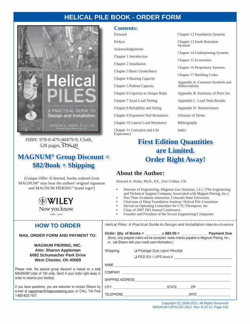
Copyright (C) 2009-2012 All Rights ReservedMAGNUM CATALOG 2012 Rev. 8-10-12, Page 216
HELICAL PILE BOOK - ORDER FORMContents:Forward
Preface
Acknowledgements
Chapter 1 Introduction
Chapter 2 Installation
Chapter 3 Basic Geotechnics
Chapter 4 Bearing Capacity
Chapter 5 Pullout Capacity
Chapter 6 Capacity-to-Torque Ratio
Chapter 7 Axial Load Testing
Chapter 8 Reliability and Sizing
Chapter 9 Expansive Soil Resistance
Chapter 10 Lateral Load Resistance
Chapter 11 Corrosion and Life Expectancy
Chapter 12 Foundation Systems
Chapter 13 Earth Retention Systems
Chapter 14 Underpinning Systems
Chapter 15 Economics
Chapter 16 Proprietary Systems
Chapter 17 Building Codes
Appendix A. Common Symbols and Abbreviations
Appendix B. Summary of Prior Art
Appendix C. Load Tests Results
Appendix D. Nomenclature
Glossary of Terms
Bibliography
Index
MAGNUM® Group Discount =$82/Book + Shipping
(Unique Offer: If desired, books ordered fromMAGNUM® may bear the authors' original signature
and MAGNUM PIERING® brand logo!)
First Edition Quantitiesare Limited.
Order Right Away!
About the Author:Howard A. Perko, Ph.D., P.E., Fort Collins, CD
• Director of Engineering, Magnum Geo Soutions, LLC (The Engineering and Technical Support Company Associated with Magum Piering, Inc.)
• Part-Time Academic Instructor, Colorado State University• Chairman of Deep Foundation Institute: Helical Pile Committee• Served on Operating Committee for CTL/Thompson, Inc• Chair of 2007 DFI Annual Conference• Founder and President of the Secure Engineering Companies
HOW TO ORDERMAIL ORDER FORM AND PAYMENT TO:
MAGNUM PIERING, INC.Attn: Sharon Appleman
6082 Schumacher Park DriveWest Chester, Oh 45069
Please note, the special group discount is based on a total MAGNUM® order of 100 units. Send in your order right away in order to reserve your book(s).
If you have questions, you are welcome to contact Sharon by e-mail at [email protected]; or CALL Toll Free 1-800-822-7437.
ISBN: 978-0-470-40479-9, Cloth,528 pages, $125.00
Helical Piles: A Practical Guide to Design and Installation (ISBN 978-0-470-40479-9)
Order: Qty. of Books = ________x $82.00 = ____________ Payment Due(Sorry, only prepaid orders will be accepted. make checks payable to Magnum Piering, Inc.; or , call Sharon with your credit card information.)
Shipping: q Postage Due Upon Receipt q FED EX / UPS Acct.# ____________________________ NAME _____________________________________________________________________
COMPANY _________________________________________________________________
SHIPPING ADDRESS _________________________________________________________
CITY ________________________________STATE ________ ZIP ____________________
TELEPHONE _______________________________________DATE ____________________

Cover for catelog.indd 1 8/12/12 10:59 AM