Embed Size (px)
Citation preview
1
Module 10: Circular Motion Dynamics 10.1 Newton’s Second Law and Circular Motion We have already shown that when an object moves in a circular orbit of radius R with angular velocity ! , it is most convenient to choose polar coordinates to describe the position, velocity and acceleration vectors. In particular, the acceleration vector is given by
!a = !R d"dt
#
$%&
'(
2
r + R d 2"
dt2 " = !R) 2!r + R* " . (10.1.1)
Then Newton’s Second Law
!F = m!a . (10.1.2)
can be decomposed into radial and tangential components Fr = !mR" 2 (circular motion) . (10.1.3) F! = mR" (circular motion) . (10.1.4) For the special case of uniform circular motion, ! = 0 and so the sum of the tangential components of the force acting on the object is must therefore be zero, F! = 0 (uniform circular motion) . (10.1.5)
10.2 Universal Law of Gravitation and the Circular Orbit of the Moon An important example of (approximate) circular motion is the orbit of the Moon around the Earth. We can approximately calculate the time T the Moon takes to complete one circle around the earth (a calculation of great importance to early lunar calendar systems, which became the basis for our current model.) Denote the distance from the moon to the center of the earth by e, mR . Since the Moon moves in a circle, it is accelerating towards the Earth. The radial acceleration has magnitude
2
e, m2
4r
Ra
T!
= . (10.2.1)
2
According to Newton’s Second Law, there must be a centripetal force acting on the Moon directed towards the center of the Earth that accounts for this inward acceleration. Universal Law of Gravitation Newton’s Universal Law of Gravitation (see Section 3.3) describes the gravitational force between two bodies 1 and 2 with masses 1m and 2m respectively. This force is a radial force (always pointing along the radial line connecting the masses) and the magnitude is proportional to the inverse square of the distance that separates the bodies. Then the force on body 1 due to the gravitational interaction between the bodies is given by Equation 3.3.11,
1 21, 1,22
1,2
ˆm mGr
= !F r!
, (10.2.2)
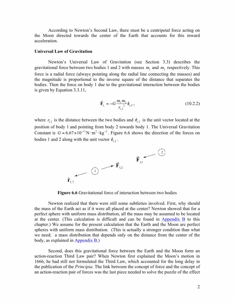
where 1,2r is the distance between the two bodies and 1,2r is the unit vector located at the position of body 1 and pointing from body 2 towards body 1. The Universal Gravitation Constant is 11 2 26.67 10 N m kgG ! != " # # . Figure 6.6 shows the direction of the forces on bodies 1 and 2 along with the unit vector 1,2r .
Figure 6.6 Gravitational force of interaction between two bodies Newton realized that there were still some subtleties involved. First, why should the mass of the Earth act as if it were all placed at the center? Newton showed that for a perfect sphere with uniform mass distribution, all the mass may be assumed to be located at the center. (This calculation is difficult and can be found in Appendix B to this chapter.) We assume for the present calculation that the Earth and the Moon are perfect spheres with uniform mass distribution. (This is actually a stronger condition than what we need; a mass distribution that depends only on the distance from the center of the body, as explained in Appendix B.) Second, does this gravitational force between the Earth and the Moon form an action-reaction Third Law pair? When Newton first explained the Moon’s motion in 1666, he had still not formulated the Third Law, which accounted for the long delay in the publication of the Principia. The link between the concept of force and the concept of an action-reaction pair of forces was the last piece needed to solve the puzzle of the effect
3
of gravity on planetary orbits. Once Newton realized that the gravitational force between any two bodies forms an action-reaction pair, and satisfies both the Universal Law of Gravitation and his newly formulated Third Law, he was able to solve the oldest and most important physics problem of his time, the motion of the planets. The test for the Universal Law of Gravitation was performed through experimental observation of the motion of planets, which turned out to be resoundingly successful. For almost 200 years, Newton’s Universal Law was in excellent agreement with observation. A sign of more complicated physics ahead, the first discrepancy only occurred when a slight deviation of the motion of Mercury was experimentally confirmed in 1882. The prediction of this deviation was the first success of Einstein’s Theory of General Relativity (formulated in 1915). We can apply this Universal Law of Gravitation to calculate the period of the Moon’s orbit around the Earth. The mass of the Moon is 22
1 7.36 10 kgm = ! and the mass of the Earth is 24
2 5.98 10 kgm = ! . The distance from the Earth to the Moon is 8
e, m 3.82 10 mR = ! . Newton’s Second Law of motion for the radial direction becomes
2
e,m1 212 2
e,m
4 Rm mG mR T
!= . (10.2.3)
We can solve this equation for the period of the orbit,
2 3
e,m
2
4 RT
Gm!
= . (10.2.4)
Substitute the given values for the radius of the orbit, the mass of the earth, and the universal gravitational constant. The period of the orbit is
( )
( )
32 86
11 2 2 24
4 3.82 10 m2.35 10 s
6.67 10 N m kg (5.98 10 kg)T
!" "
#= = #
# $ $ #. (10.2.5)
This period is given in days by
T = 2.35!106 s( ) 1 day
8.64 !104 s"
#$%
&'= 27.2 days. (10.2.6)
This period is called the sidereal month because it is the time that it takes for the Moon to return to a given position with respect to the stars.
4
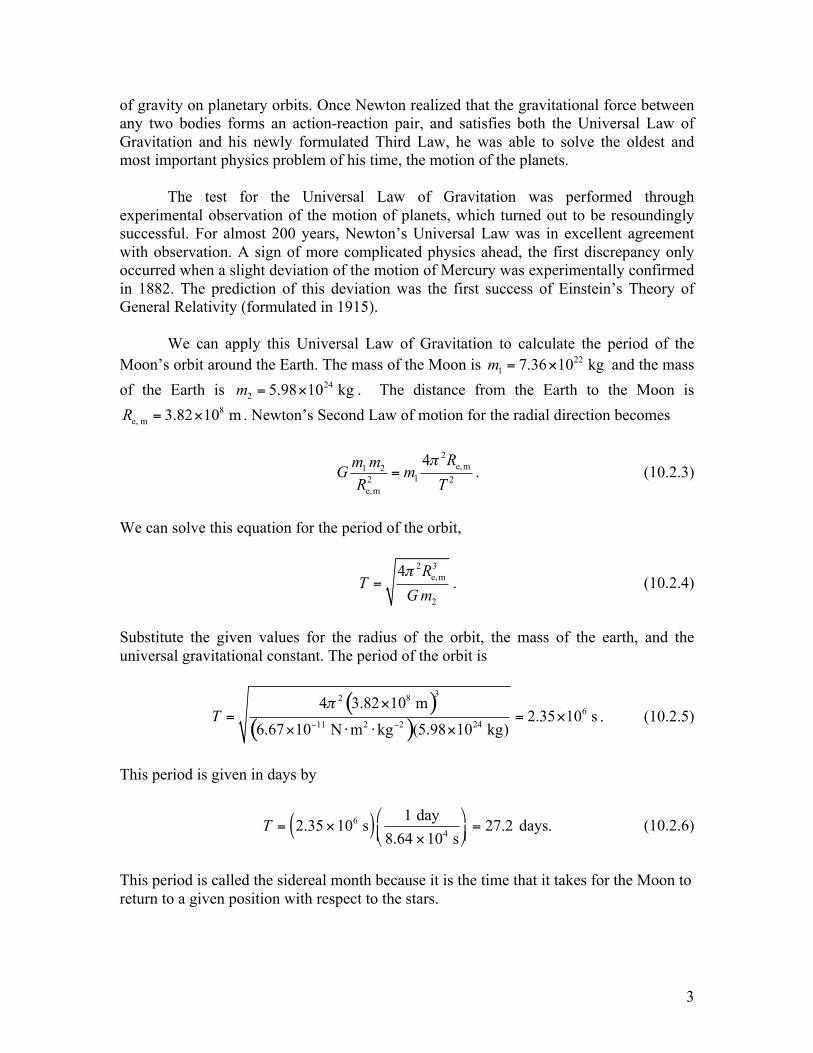
The actual time T1 between full moons, called the synodic month (the average period of the Moon’s revolution with respect to the sun and is 29.53 days, it may range between 29.27 days and 29.83 days), is longer than the sidereal month because the Earth is traveling around the Sun. So for the next full moon the Moon must travel a little farther than one full circle around the Earth in order to be on the other side of the Earth from the Sun.
Therefore the time T1 between consecutive full moons is approximately T1 ! T + !T where !T ! T / 12 = 2.3 days . So T1 ! 29.5 days . Kepler’s Third Law and Circular Motion The first thing that we notice from the above solution is that the period does not depend on the mass of the Moon. We also notice that the square of the period is proportional to the cube of the distance between the Earth and the Moon,
2 3
e,m2
2
4 RT
Gm!
= . (10.2.7)
This is an example of Kepler’s Third Law, of which Newton was aware. This
confirmation was convincing evidence to Newton that his Universal Law of Gravitation was the correct mathematical description of the gravitational force law, even though he still could not explain what “caused” gravity. Worked Examples Circular Motion Example 1: A geostationary satellite goes around the earth once every 23 hours 56 minutes and 4 seconds, (a sidereal day, shorter than the noon-to-noon solar day of 24 hours) so that its position appears stationary with respect to a ground station. The mass of the earth is me = 5.98 !1024 kg . The mean radius of the earth is 6
e 6.37 10 mR = ! . The
universal constant of gravitation is G = 6.67 !10"11 N #m2 #kg"2 . Your goal is to find the radius of the orbit of a geostationary satellite. Describe what motion models this problem. What is the radius of the orbit of a geostationary satellite? Approximately how many earth radii is this distance?
5
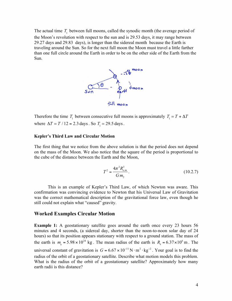
Solution: The satellite’s motion can be modeled as uniform circular motion. The gravitational force between the earth and the satellite keeps the satellite moving in a circle. The acceleration of the satellite is directed towards the center of the circle, that is, along the radially inward direction. The figure below is close to a scale drawing.
Choose the origin at the center of the earth, and the unit vector r along the radial direction. This choice of coordinates makes sense in this problem since the direction of acceleration is along the radial direction. Let r! be the position vector of the satellite. The magnitude of r! (we denote it as sr ) is the distance of the satellite from the center of the earth, and hence the radius of its circular orbit. Let ! be the angular velocity of the satellite, and the period is T = 2! / " . The acceleration is directed inward, with magnitude 2
sr! ; in vector form, 2
s ˆr!= "a r! . (2.8) Apply Newton’s Second Law to the satellite for the radial component. The only force in this direction is the gravitational force due to the Earth, 2
grav s s ˆF m r!= " r!
. (2.9) The inward radial force on the satellite is the gravitational attraction of the earth,
2s es s2
s
ˆ ˆm mG m rr
!" = "r r . (2.10)
Equating the r components,
6
2s es s2
s
m mG m rr
!= . (2.11)
Solving for the radius of orbit of the satellite rs ,
1/3
es 2
Gmr!
" #= $ %& '
. (2.12)
The period T of the satellite’s orbit in seconds is 86164 s and so the angular speed is
5 12 2 7.2921 10 s86164 sT
! !" # #= = = $ . (2.13)
Using the values of e, andG m! in Equation (2.12), we determine sr ; 7
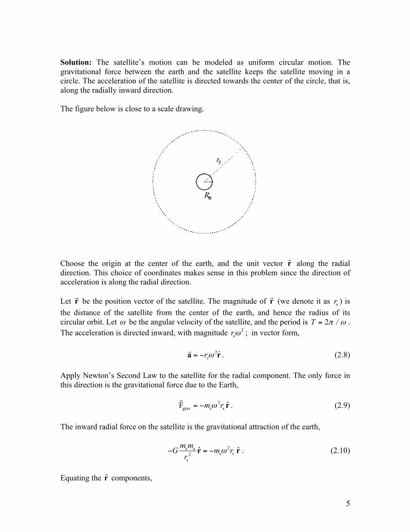
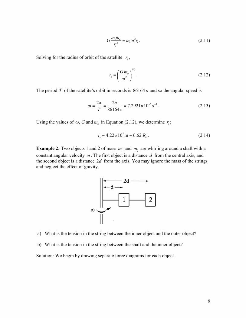
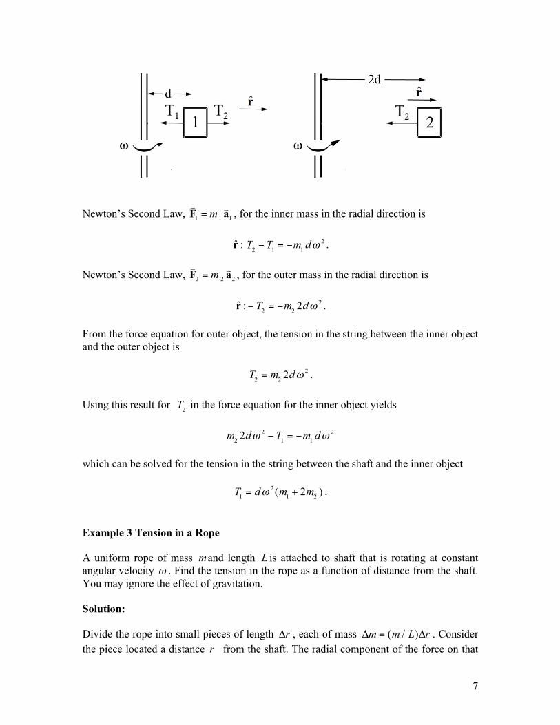
s e4.22 10 m 6.62r R= ! = . (2.14) Example 2: Two objects 1 and 2 of mass m1 and m2 are whirling around a shaft with a constant angular velocity ! . The first object is a distance d from the central axis, and the second object is a distance 2d from the axis. You may ignore the mass of the strings and neglect the effect of gravity.
a) What is the tension in the string between the inner object and the outer object? b) What is the tension in the string between the shaft and the inner object? Solution: We begin by drawing separate force diagrams for each object.
7
Newton’s Second Law, 1 1 1m=F a
! ! , for the inner mass in the radial direction is
r : T2 ! T1 = !m1 d" 2 . Newton’s Second Law, 2 2 2m=F a
! ! , for the outer mass in the radial direction is
r :! T2 = !m2 2d" 2 . From the force equation for outer object, the tension in the string between the inner object and the outer object is
T2 = m2 2d! 2 .
Using this result for T2 in the force equation for the inner object yields
m2 2d! 2 " T1 = "m1 d! 2 which can be solved for the tension in the string between the shaft and the inner object
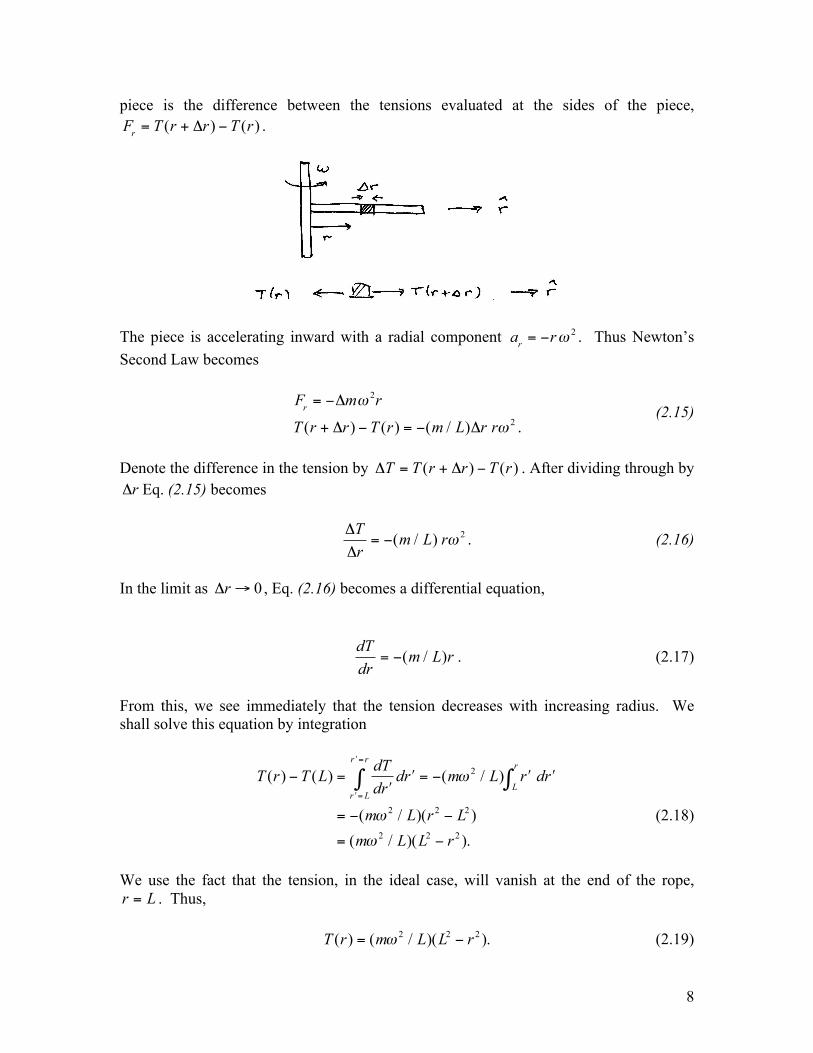
T1 = d! 2 (m1 + 2m2 ) . Example 3 Tension in a Rope A uniform rope of mass mand length L is attached to shaft that is rotating at constant angular velocity ! . Find the tension in the rope as a function of distance from the shaft. You may ignore the effect of gravitation. Solution: Divide the rope into small pieces of length !r , each of mass !m = (m / L)!r . Consider the piece located a distance r from the shaft. The radial component of the force on that
8
piece is the difference between the tensions evaluated at the sides of the piece,
Fr = T (r + !r) " T (r) .
The piece is accelerating inward with a radial component ar = !r" 2 . Thus Newton’s Second Law becomes
Fr = !"m# 2r
T (r + "r) ! T (r) = !(m / L)"r r# 2 . (2.15)
Denote the difference in the tension by !T = T (r + !r) " T (r) . After dividing through by !r Eq. (2.15) becomes
!T!r
= "(m / L) r# 2 . (2.16)
In the limit as !r " 0 , Eq. (2.16) becomes a differential equation,
dTdr
= !(m / L)r . (2.17)
From this, we see immediately that the tension decreases with increasing radius. We shall solve this equation by integration
T (r) ! T (L) =dTd "r"r = L
"r = r
# d "r = !(m$ 2 / L) "rL
r
# d "r
= !(m$ 2 / L)(r 2 ! L2 )= (m$ 2 / L)(L2 ! r 2 ).
(2.18)
We use the fact that the tension, in the ideal case, will vanish at the end of the rope, r = L . Thus, T (r) = (m! 2 / L)(L2 " r 2 ). (2.19)
9
This last expression shows the expected functional form, in that the tension is largest closest to the shaft, and vanishes at the end of the rope.
10
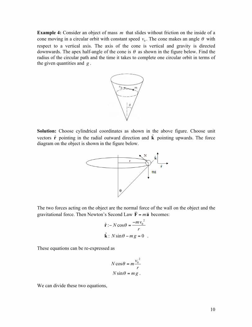
Example 4: Consider an object of mass m that slides without friction on the inside of a cone moving in a circular orbit with constant speed 0v . The cone makes an angle ! with respect to a vertical axis. The axis of the cone is vertical and gravity is directed downwards. The apex half-angle of the cone is ! as shown in the figure below. Find the radius of the circular path and the time it takes to complete one circular orbit in terms of the given quantities and g .
Solution: Choose cylindrical coordinates as shown in the above figure. Choose unit vectors r pointing in the radial outward direction and k pointing upwards. The force diagram on the object is shown in the figure below.
The two forces acting on the object are the normal force of the wall on the object and the gravitational force. Then Newton’s Second Law m=F a
! ! becomes: 20ˆ : cos
mvNr
!"
" =r
ˆ : sin 0N mg! " =k . These equations can be re-expressed as
20cosvN mr
! =
sinN mg! = . We can divide these two equations,
11
20
sincos
N mgvN mr
!!=
yielding
20
tan r gv
! = .
This can be solved for the radius,
20 tanvrg
!= .
The centripetal force in this problem is the vector component of the contact force that is pointing radially inwards,
cent cos cotF N mg! != = ,
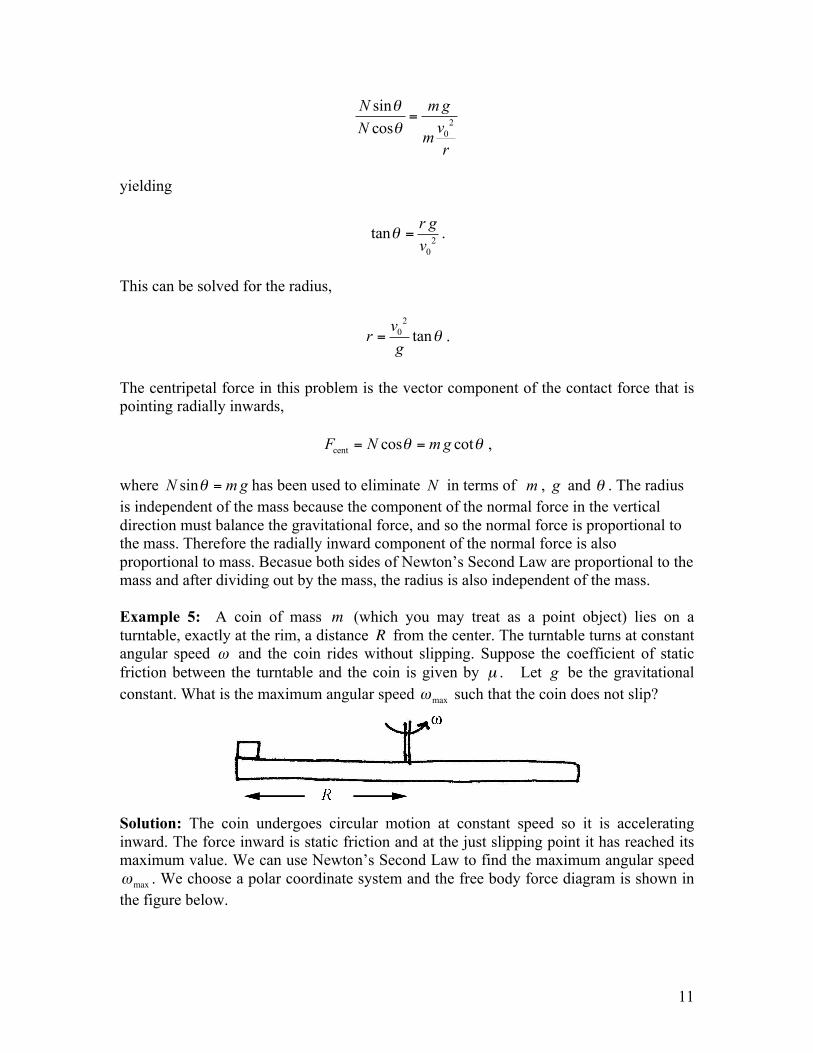
where sinN mg! = has been used to eliminate N in terms of m , g and ! . The radius is independent of the mass because the component of the normal force in the vertical direction must balance the gravitational force, and so the normal force is proportional to the mass. Therefore the radially inward component of the normal force is also proportional to mass. Becasue both sides of Newton’s Second Law are proportional to the mass and after dividing out by the mass, the radius is also independent of the mass. Example 5: A coin of mass m (which you may treat as a point object) lies on a turntable, exactly at the rim, a distance R from the center. The turntable turns at constant angular speed ! and the coin rides without slipping. Suppose the coefficient of static friction between the turntable and the coin is given by µ . Let g be the gravitational constant. What is the maximum angular speed !max such that the coin does not slip?
Solution: The coin undergoes circular motion at constant speed so it is accelerating inward. The force inward is static friction and at the just slipping point it has reached its maximum value. We can use Newton’s Second Law to find the maximum angular speed !max . We choose a polar coordinate system and the free body force diagram is shown in the figure below.
12
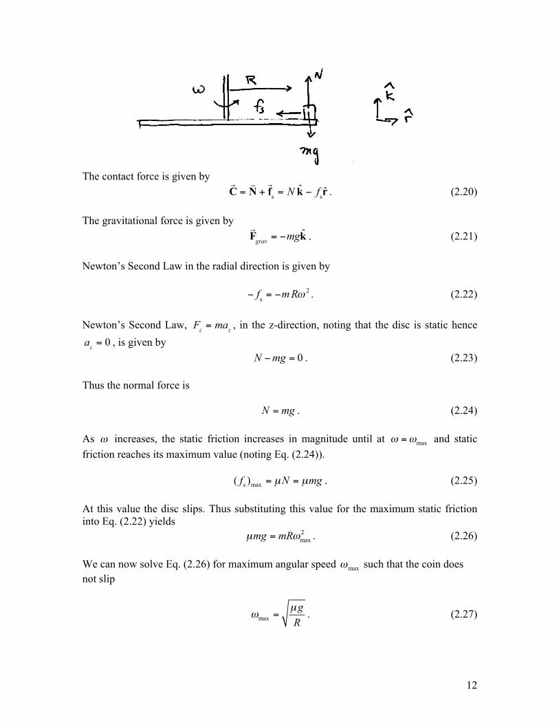
The contact force is given by
!C =!N +!fs = N k ! fsr . (2.20)
The gravitational force is given by
!Fgrav = !mgk . (2.21)
Newton’s Second Law in the radial direction is given by ! fs = !m R" 2 . (2.22) Newton’s Second Law, Fz = maz , in the z-direction, noting that the disc is static hence
az = 0 , is given by 0N mg! = . (2.23) Thus the normal force is N mg= . (2.24) As ! increases, the static friction increases in magnitude until at max! != and static friction reaches its maximum value (noting Eq. (2.24)). s max( )f N mgµ µ= = . (2.25) At this value the disc slips. Thus substituting this value for the maximum static friction into Eq. (2.22) yields 2
maxmg mRµ != . (2.26) We can now solve Eq. (2.26) for maximum angular speed !max such that the coin does not slip
maxgRµ
! = . (2.27)
13
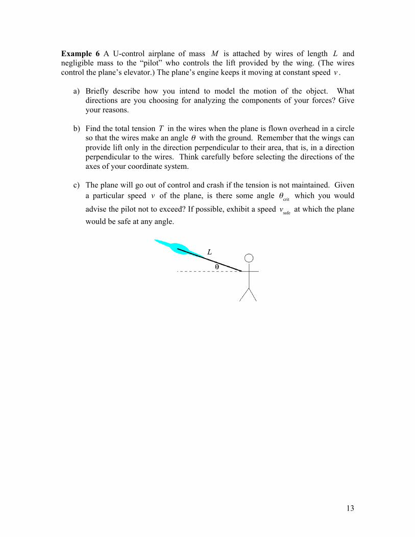
Example 6 A U-control airplane of mass M is attached by wires of length L and negligible mass to the “pilot” who controls the lift provided by the wing. (The wires control the plane’s elevator.) The plane’s engine keeps it moving at constant speed v .
a) Briefly describe how you intend to model the motion of the object. What directions are you choosing for analyzing the components of your forces? Give your reasons.
b) Find the total tension T in the wires when the plane is flown overhead in a circle
so that the wires make an angle ! with the ground. Remember that the wings can provide lift only in the direction perpendicular to their area, that is, in a direction perpendicular to the wires. Think carefully before selecting the directions of the axes of your coordinate system.
c) The plane will go out of control and crash if the tension is not maintained. Given
a particular speed v of the plane, is there some angle !crit which you would
advise the pilot not to exceed? If possible, exhibit a speed vsafe at which the plane would be safe at any angle.
14
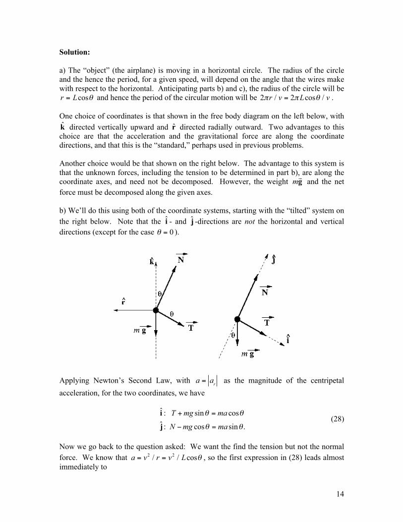
Solution: a) The “object” (the airplane) is moving in a horizontal circle. The radius of the circle and the hence the period, for a given speed, will depend on the angle that the wires make with respect to the horizontal. Anticipating parts b) and c), the radius of the circle will be r = Lcos! and hence the period of the circular motion will be 2!r / v = 2!Lcos" / v . One choice of coordinates is that shown in the free body diagram on the left below, with k directed vertically upward and r directed radially outward. Two advantages to this choice are that the acceleration and the gravitational force are along the coordinate directions, and that this is the “standard,” perhaps used in previous problems. Another choice would be that shown on the right below. The advantage to this system is that the unknown forces, including the tension to be determined in part b), are along the coordinate axes, and need not be decomposed. However, the weight mg! and the net force must be decomposed along the given axes. b) We’ll do this using both of the coordinate systems, starting with the “tilted” system on the right below. Note that the i - and j -directions are not the horizontal and vertical directions (except for the case ! = 0 ).
Applying Newton’s Second Law, with
a = ar as the magnitude of the centripetal acceleration, for the two coordinates, we have
ˆ : sin cosˆ : cos sin .
T mg ma
N mg ma
! !
! !
+ =
" =
i
j (28)
Now we go back to the question asked: We want the find the tension but not the normal force. We know that a = v2 / r = v2 / Lcos! , so the first expression in (28) leads almost immediately to
15
T = m v2 / L ! g sin"( ) , (29) a very tidy result. If we used the coordinate system on the left above, Newton’s Second Law becomes
ˆ : cos sinˆ : sin cos .N T mgN T ma
! !
! !
" =
+ =
kr
(30)
The expressions in (30) are two equations in the two unknowns N and T and may be solved by standard methods. For our immediate purpose, however, eliminate N by multiplying the first by sin! and the second by cos! and then subtract the first from the second, leading to Equation (29). Decide for yourself which coordinate system is “better” or “easier,” but keep in mind that either will work. c) Either way, we are now set to find the critical angle crit! at which the tension as found in Equation (29) would go to zero,
!crit = sin"1 v2
gL#
$%&
'(. (31)
We see that if v
2 > gL , the critical angle is never reached, and all angles would be safe, so we have vsafe = gL . (32) Notice that if ! = 0 the rope lies in the plane of the airplane’s circular orbit, sin! = 0 , and the tension T = mv2 / L > 0 for all velocities (assuming the normal force N
!, acting
vertically upward, is sufficient to keep the plane flying). The other extreme value occurs when ! " # / 2 . This corresponds to the radius of the orbit r ! 0 , cos! " 1 and the tension
T ! mv2 / L( ) " mg . In order for the tension to stay positive, v > gL (which is
consistent with !crit "# / 2 ). Extra: This problem did not ask for the normal force N
! (often called the “lift”), but it’s
not hard to find
N = mg v2 / L( ) tan! + cos!( ) . (33)
From this we see that as ! " # / 2 , N !" and r ! 0 , an unphysical result.
16
17
Appendix 6.B: The Gravitational Field of a Spherical Shell of Matter Consider a spherical shell of radius R with mass Sm that is uniformly distributed
over the shell with mass per unit area S24
mR
!"
= .
In this appendix we will show the following two properties of the gravitational force that such a shell produces:
1) The gravitational force on a point-like object of mass m placed outside a spherical shell of matter of uniform surface mass density ! is the same force that would arise if all the mass of the shell were located at the center of the sphere.
2) The gravitational force on an object of mass m placed inside a spherical shell of
matter is zero. In summary,
( )S
2object ,S
ˆ,
,
mmG r Rr r
r R
!" >#= $# <%
rF
0
!! (6.C.1)
where r is the unit vector located at the position of the object and pointing radially away from the center of the shell. We will use these properties to extend the results to the gravitational interaction between any two spherically symmetric bodies. Any rigorous derivation of the above result will require use of spherical coordinates. This appendix will not go into the details of spherical coordinates, but rely on the geometry suggested by Figure 6.B.1 below. For a point on the surface of a sphere of radius r R= , the Cartesian coordinates are related to the spherical coordinates by
sin cossin sincos
x Ry Rz R
! "
! "
!
=
=
=
(6.C.2)
where 0 θ π≤ ≤ and 0 2φ π≤ ≤ . You should be able to show quite easily that 2 2 2 2x y z R+ + = . You might also note that the angle θ in Figure 6.B.1 and Equations (6.C.2) is not the same as that in plane polar coordinates or cylindrical coordinates as shown in Figure 6.1 of the text. The relations in
18
Figure 6.B.1 and Equations (6.C.2) are “Physics Notation,” as opposed to what is done in most math subjects and textbooks. The age-old arguments for and against each system will not be presented here. However, keep in mind two good reasons for using physics notation:
• In most problems and derivations involving spherical symmetry, including this appendix, the angle θ will have a more prominent role than the angle φ and hence is given the more customary symbol for an angle.
• As shown in Figure 6.B.1, we still have at any point on the sphere a right-handed
coordinate system, with ˆˆ ˆ× =r θ φ , directed counterclockwise when viewed from above (from the positive z -direction). (The symbol “φ ” is the bold form of “φ ”, and hence is used for the unit vector is the φ -direction.) Compare to ˆ ˆˆ× =r θ k in cylindrical coordinates.
The angle θ is known as the colatititude, the complement of the latitude. We can and will choose our z -axis to be directed from the center of the sphere to the position of the object, at position 0
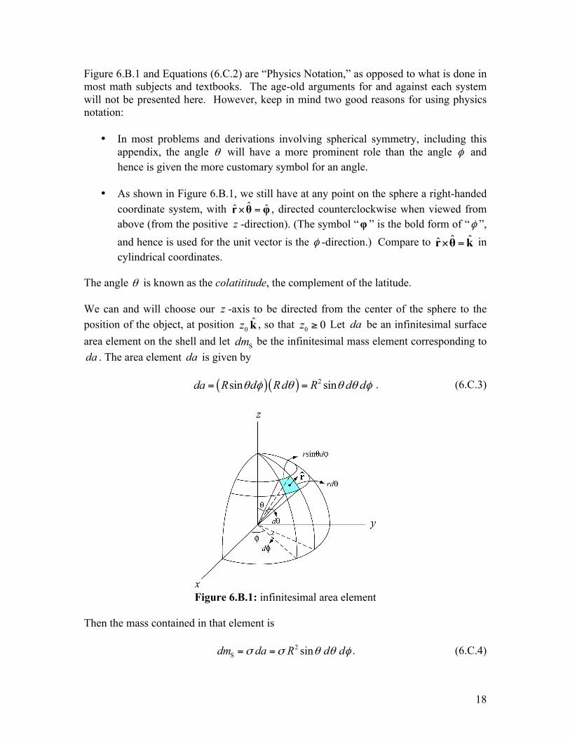
ˆz k , so that 0 0z ≥ Let da be an infinitesimal surface area element on the shell and let Sdm be the infinitesimal mass element corresponding to da . The area element da is given by ( )( ) 2sin sinda R d Rd R d dθ φ θ θ θ φ= = . (6.C.3)
Figure 6.B.1: infinitesimal area element
Then the mass contained in that element is 2
S sindm da R d dσ σ θ θ φ= = . (6.C.4)
19
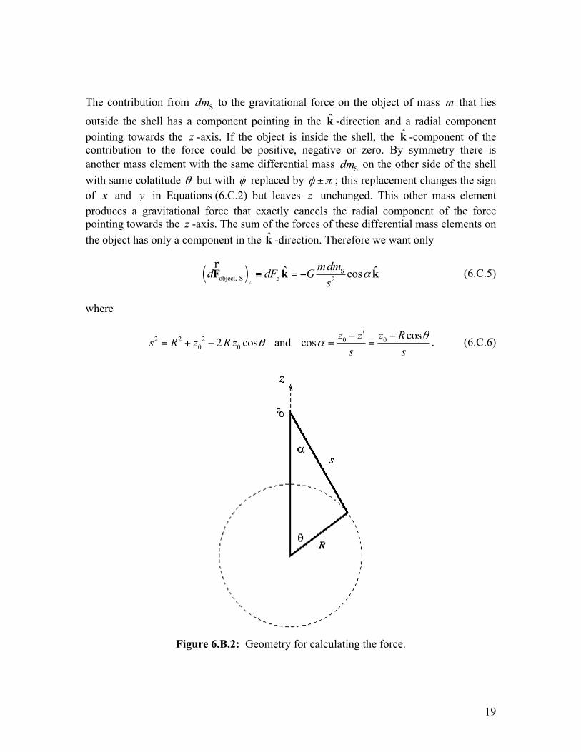
The contribution from Sdm to the gravitational force on the object of mass m that lies
outside the shell has a component pointing in the k -direction and a radial component pointing towards the z -axis. If the object is inside the shell, the k -component of the contribution to the force could be positive, negative or zero. By symmetry there is another mass element with the same differential mass Sdm on the other side of the shell with same colatitude θ but with φ replaced by φ π± ; this replacement changes the sign of x and y in Equations (6.C.2) but leaves z unchanged. This other mass element produces a gravitational force that exactly cancels the radial component of the force pointing towards the z -axis. The sum of the forces of these differential mass elements on the object has only a component in the k -direction. Therefore we want only
( ) Sobject, S 2
ˆ ˆcoszz
mdmd dF Gs
α≡ = −F k kr
(6.C.5)
where
2 2 2 0 00 0
cos2 cos and cos z z z Rs R z R zs s
θθ α
ʹ′− −= + − = = . (6.C.6)
Figure 6.B.2: Geometry for calculating the force.
20
In Equation (6.C.6), s is the distance from any point on the ring to the position of the object, zʹ′ is the distance along the z -axis from the center of the shell to the plane of the differential ring and α is the angle that the vector of magnitude s from any point on the ring to the object makes with respect to the z -axis. The geometry is shown in Figure 6.B.2 above. The circle in the figure is a cross-section of the spherical shell. Combining Equations (6.C.4), (6.C.5) and both expressions in (6.C.6),
( )( )
20S S
3 22 2 2 20 0
sin coscos
4 2 cosz
R d d z Rmdm mmdF G Gs R R z R z
θ θ φ θα
π θ
−= − = −
+ −. (6.C.7)
The expression in Equation (6.C.7) can be simplified in preparation for integration. Make a change of variables by letting 0 cosu z R θ= − . Then sindu R dθ θ= and 2 2 2 2 2
0 0 0 02 cos 2s R z R z R u z zθ= + − = + − . (6.C.8) Substitution of Equation (6.C.8) and the expression for u and du gives
( )
s3 22 2 2
0 04 2
zmm RududdF GR R u z z
φπ
= −+ −
. (6.C.9)
When ! = 0 , 0u z R= − ; when ! = " , 0u z R= + . Thus the double integral becomes
( )
2 2s
3 22 20 0 0 0
4 2
u z R u z R
z zu z R u z R
m m u du dF dF GR R u z z
φ π φ π
φ φ
φπ
= == + = +
= − = = − =
= = −+ −
∫ ∫ ∫ ∫ (6.C.10)
We first integrate with respect to the ! -coordinate, contributing a multiplicative factor of 2! because the integrand is independent of ! . The double integral is then
( )
S3 22 2
0 0
24 2
u z R
zu z R
mm u duF GR R u z z
ππ
= +
= −
= −+ −
∫ . (6.C.11)
The above indefinite integral is not in everyone’s toolkit, and not in many standard integral tables. (For those so inclined, a MAPLE worksheet that does the integral is given in the link at the end of this subsection.) One successful approach is to rewrite the numerator of the integrand as
( ) ( )2 2 2 2
2 2 2 20 0 00 0 0
0 0
2 1 22 2
R u z z R zu R u z z z Rz z
+ − − + ⎡ ⎤= = + − + −⎣ ⎦ . (6.C.12)
21
The indefinite integral, apart from the leading constants, is then
( )( )
2 20 3/ 22 2 2 2
0 0 0 0 0
12 2 2
du duz Rz R u z z R u z z
⎡ ⎤⎢ ⎥+ −⎢ ⎥+ − + −⎣ ⎦∫ . (6.C.13)
These integrals are certainly in recognizable forms, leading to
( )
( )
0
0
2 202 2S
0 02 2 20 0 0
2 22 202 2S 0
0 0 02 2 20 0 0 0
1 22 2 2
1 22 2 2
u z R
z
u z R
z RmmF G R u z zR z R u z z
z Rmm z RG z R R z R zR z z R R z R z
= +
= −
⎛ ⎞−⎜ ⎟= − + − −⎜ ⎟+ −⎝ ⎠
⎛ ⎞⎛ ⎞−⎛ ⎞−⎜ ⎟⎜ ⎟= − + − − − + −⎜ ⎟ ⎜ ⎟⎜ ⎟+ − +⎝ ⎠ ⎝ ⎠⎝ ⎠
(6.C.14)
Now there is a subtlety. Since 2 2
0 02R z R z− + is always positive, we have two special cases:
0 02 20 0
0 0
,2
, .z R z R
R z R zR z z R− >⎧
− + = ⎨− <⎩
(6.C.15)
Then for 0z R> ,
( )( ) ( )( )0 0 0 0S0 02
0 0 0
S S2 20 0
12 2
1 4 .2 2
zz R z R z R z RmmF G z R z R
R z z R z R
mm mmG R GR z z
⎛ ⎞⎛ ⎞ ⎛ ⎞+ − + −= − + − − − −⎜ ⎟⎜ ⎟ ⎜ ⎟⎜ ⎟+ −⎝ ⎠ ⎝ ⎠⎝ ⎠
= − = −
(6.C.16)
For 0z R< ,
( )( ) ( )( )0 0 0 0S
0 020 0 0
12 2
0
zz R z R z R z RmmF G z R R z
R z z R R z⎛ ⎞⎛ ⎞ ⎛ ⎞+ − + −
= − + − − − −⎜ ⎟⎜ ⎟ ⎜ ⎟⎜ ⎟+ −⎝ ⎠ ⎝ ⎠⎝ ⎠=
(6.C.17)
Collecting the results in Equations (6.C.16) and (6.C.17),

22
020
0
,
0 , ,
S
z
mmG z RzF
z R
⎧− >⎪= ⎨⎪ <⎩
(6.C.18)
consistent with the stated goal as in (6.C.1). A MAPLE worksheet that will perform the integral in Equation (6.C.11) (crude, but it works) may be downloaded here. Note that in this worksheet, the two cases must be considered separately, with the conditions entered in separate command lines. This proves the result that the gravitational force inside the shell is zero and the gravitational force outside the shell is equivalent to locating all the mass of the object at the center of the shell. For some other spherically symmetric distribution, the attracting mass could be divided into concentric spherical shells and the above result applied to each shell. In general, this would involve an integral, and the limits of the integral would depend on whether or not the object is outside all of the layers or outside some and inside others. If the object were itself a spherically symmetric body, not necessarily point-like, it can be seen that the same result holds, with 0z replaced with the center of mass of the body, by considering that we have shown that the original attracting body behaves gravitationally like a point mass. From Newton’s Third Law we could reverse the argument and say that the object behaves like a point mass. If the bodies overlap, as might be expected with gaseous spheres, this argument will not hold, but such bodies are not likely to be spherical. Exercise Left to the Reader: What if 0z R= ? For gravity, this is not likely these days (but some folks are thinking about it), but for E&M purposes it might be of concern. Hint: Use 0z R= in both equations in (6.C.6), simplify as much as you can, and substitute into the integral in (6.C.5). Use the half-angle formulas
21 cos 2sin2
sin 2sin cos2 2
θθ
θ θθ
⎛ ⎞− = ⎜ ⎟⎝ ⎠
⎛ ⎞ ⎛ ⎞= ⎜ ⎟ ⎜ ⎟⎝ ⎠ ⎝ ⎠
(6.C.19)
and you’re essentially done.
23
Alternate Method of Integration: The integral in Equation (6.C.5), apart from multiplicative constants and the subsequent φ -integral, can be expressed
2
cos sin dsα θ
θ∫ , (6.C.20)
where the θ -dependence of Sdm is given explicitly. What we will do is change the integration variable to s , and so we’ll need relations between the angles α and θ , and the lengths s , 0z and R . Consider a triangle with sides of lengths s , 0z and R , with α between the sides of lengths 0z and s , and θ between the sides of lengths 0z and R . (This is the triangle shown in Figure 6.A.2 above.) Using the law of cosines twice,
2 2 2
0 0
2 2 20 0
2 cos
2 cos .
s R z R z
R z s s z
θ
α
= + −
= + − (6.C.21)
Differentiating the first expression in (6.C.21), with R and 0z constant, 02 2 sinsds R z dθ θ= , (6.C.22) and from the second expression in (6.C.21),
( )2 20
0
1 1cos2
z R sz s
α ⎡ ⎤= − +⎢ ⎥⎣ ⎦. (6.C.23)
We now have everything we need in terms of s . Substituting Equations (6.C.23), (6.C.22) and the first expression in (6.C.21) into (6.C.20), and using the limits for the definite integral for 0z R> ,
( )
( )
0
0
0 0
0 0
2 202 2
0 00
2 202 2
0
cos sin 1 1 12
1 .2
z R
z R
z R z R
z R z R
s dsd z R ss z s s R z
dsz R dsR z s
θ π
θ
α θθ
=+
−=
+ +
− −
⎡ ⎤= − +⎢ ⎥⎣ ⎦
⎡ ⎤= − +⎢ ⎥⎣ ⎦
∫ ∫
∫ ∫ (6.C.24)
No tables should be needed for these; the result is
24
( )( ) ( )
0
0
2 20
0 02 20 0
20
1 1 22 2
2 ,
z R
z R
R zs R z R z R
R z s R z
z
+
−
⎡ ⎤−+ = − + + +⎡ ⎤⎢ ⎥ ⎣ ⎦
⎢ ⎥⎣ ⎦
=
(6.C.25)
the expected result when the multiplicative constants are included. For 0z R< , the lower limit is 0R z− , and the integral is
( )
( ) ( )0
0
2 20
0 0 02 20 0
1 1 22 2
0,
z R
R z
R zs R z R z z
R z s R z
+
!
" #!+ = ! ! + +" #$ % & '
$ %& '
=
(6.C.26)
again the expected result.
25
MIT OpenCourseWare http://ocw.mit.edu 8.01SC Physics I: Classical Mechanics For information about citing these materials or our Terms of Use, visit: http://ocw.mit.edu/terms.