Embed Size (px)
Citation preview

HVAC – Space Heating Systems Course No: M06-025
Credit: 6 PDH
A. Bhatia
Continuing Education and Development, Inc. 9 Greyridge Farm Court Stony Point, NY 10980 P: (877) 322-5800 F: (877) 322-4774 [email protected]
HVAC - SPACE HEATING SYSTEMS
Maintaining comfort is not a matter of supplying heat to the body. Instead, it’s a matter of
controlling how the body loses heat. "Thermal comfort" is a measure of a person's satisfaction
with his or her surroundings, and is achieved when a desirable heat balance between the body
and surroundings are met. Since there is no single ideal comfort point for any group of people, a
range of values are described as the ideal thermal zone. These conditions are:
1. Air temperatures between 60-72°F, dependant upon the type of activity being carried out,
age of occupants and the level and quality of clothing;
2. Air temperature at feet level, not greater than 5.4°F below that at head level;
3. Airflow past the body is horizontal and at velocity ranging between 40 and 50 feet per
minute. A variable air velocity is preferable to a constant one;
4. Room surface temperatures not above the air temperatures;
5. Relative humidity between 40%- 60%.
The heating system design can have lot of options; the three main considerations in the selection
of a heating system are: 1) low installation cost, 2) low operating and maintenance cost, and 3)
adequate control of space conditions.
In this course, we will categorize heating systems in several ways. First we will consider where
the primary energy comes from. Then we will compare the various options and discuss the variety
of ways used to deliver heat within the space and finally, some general guidelines on the energy
conservation and application strategies for various buildings. The course is divided in six
sections:
Section # 1 The Basics of Heat Loss
Section # 2 Application Considerations – Fuel Choices
Section # 3 Types of Heating Systems
Section # 4 Gas & Oil Fired Space Heating Systems
Section # 5 Hot Water Heating Systems
Section # 6 Electrical Heating Systems
Annexure # 1 Industry Standards & Codes
Annexure # 2 Heating Equipment Characteristics
Annexure # 3 Application Considerations for various systems
Annexure # 4 Energy Conservation & Load Reduction Strategies
This course reviews the above criteria in detail and is followed by a course summary and multiple-
choice quiz at the end.
SECTION 1 THE BASICS OF HEAT LOSS
In this section, we will examine
1. How heat loss occurs?
2. How to size the heating system?
3. How to extrapolate your heat loss results into an annual energy usage rate?
4. How to estimate the annual cost of heating?
5. Basis of selecting appropriate heating source.
How Heat Loss Occurs?
Heat loss occurs from a building envelope whenever the interior temperature exceeds
the exterior temperature. The rate at which it occurs is affected primarily by the efficiency
of the covering materials (glazing, roof, side walls, doors, window frames and end walls).
Heat loss is typically expressed in terms of total British Thermal Units per Hour (BTU/h)
and is given by:
Q = A x U x ∆T
Where:
• Q = heat loss, BTUH or BTU/hr
• A = area of the surface, square feet
• U = heat transfer coefficient, BTUH per sq ft per °F
• ∆T = temperature difference between inside and outside, °F
For example: 10 sq. ft. of single glass with U value of 1.13, an inside temperature of 70°F
and an outside temperature of 0° would have 791 BTU/h heat loss: A (10) x U (1.13) x
∆T (70 - 0) = 791 BTU/h.
The most commonly discussed parameters and the factors affecting heat loss are
conduction, temperature and infiltration.
1. Conduction is heat flow through a material from hot to cold. The materials used
in the construction of a building determine the level of conductivity. Insulating the
building structure slows the flow of heat. R-value is a measure of insulation; the
larger the R-value, the lesser is the heat loss. “U” factor is the inverse of “R”
factor, (“U” = 1 / “R”); the lower the “U” factor, the less ability of the material to
transfer heat; therefore, the lower the heat loss.

2. Temperature difference between the inside and outside of the building is the
primary cause of heat loss in the winter months. The greater this difference, the
higher the rate of heat loss. Since most buildings are controlled to a constant
inside temperature by the occupants, higher heat loss occurs when it is colder
outside.
3. Wind and infiltration – Heat loss from a building can also occur through
infiltration: the leakage of air into a building through cracks, poorly fitted windows
and doors, chimneys and other breaks in the continuity of the enclosure. High
winds can occur on cold nights, and when they do, heat loss can be higher
because of air scrubbing the outside of the space covering. Winds can also force
their way through cracks in the structure, causing infiltration and drafts. In fact,
the studies indicate that up to one-third of the annual heating energy goes to heat
this moving infiltration air. Shrubs and windbreaks to keep the high winds from
impacting the walls will help reduce this energy loss.
Heating System Sizing
The first step in designing heating system is finding out how much heat is needed. The
heating load of a space depend on climate, size, and style of building; insulation levels;
air tightness; amount of useful solar energy through windows; amount of heat given off
by lights and appliances; thermostat setting; and other operational factors. Together,
these factors determine how much heat must be put into the space by the heating
system over the annual heating season. This number, usually expressed as BTU per
year, can be estimated by a heat loss calculation. The overall heat loss from buildings is
divided into three groups:
1. The heat transmission losses through the confining walls, floor, ceiling, glass, or
other surfaces,
2. Perimetric heat loss through floor slab, and
3. The infiltration losses through cracks and openings, or heat required to warm
outdoor air used for ventilation.
Heat loss estimation shall be made on the worst scenario. The important points to note
are:
a. The heat loss calculations are made on most unfavorable but economical
combination of temperature and wind speed.
b. Credit for the heat of people present in the building is normally not taken since
the building could be unoccupied.
c. Internal heat gain from lighting and appliances is usually neglected.
d. Inside design temperature for most commercial and residential spaces is 65°F.
Heat Loss from Building Envelope (wall, roof, glazing etc)
The hourly rate of heat loss from the building envelope is given by equation:
Q = U x A x (Ti - Ta)
Where
• Q = total hourly rate of heat loss in BTUH
• A = area of the surface, square feet; the value measured from building plan and
elevation drawings
• U = heat transfer coefficient, BTUH per sq ft per °F; the value dependent on the
thickness and materials of construction
• Ti = inside design temperature in °F; the recommended value is 65°F
• To = outside design temperature in °F; look up by geographical location and refer
to ASHRAE handbook
Let's examine each one of these terms, starting from the bottom.
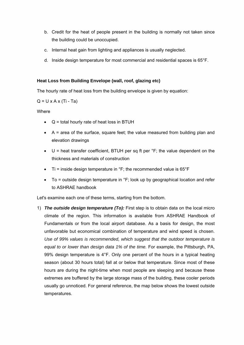
1) The outside design temperature (To): First step is to obtain data on the local micro
climate of the region. This information is available from ASHRAE Handbook of
Fundamentals or from the local airport database. As a basis for design, the most
unfavorable but economical combination of temperature and wind speed is chosen.
Use of 99% values is recommended, which suggest that the outdoor temperature is
equal to or lower than design data 1% of the time. For example, the Pittsburgh, PA,
99% design temperature is 4°F. Only one percent of the hours in a typical heating
season (about 30 hours total) fall at or below that temperature. Since most of these
hours are during the night-time when most people are sleeping and because these
extremes are buffered by the large storage mass of the building, these cooler periods
usually go unnoticed. For general reference, the map below shows the lowest outside
temperatures.

2) The inside design temperature (Ti) is traditionally taken as 65°F, because most
buildings have people, lights, and equipment that will reduce the occupied heating
requirement in comparison to the unoccupied winter night loads. But there are
numerous exceptions such as warehouses and hospitals.
3) The net area (A) of each building section is determined from the drawings (in new
construction) or from field measurements (in retrofit situations). In addition to the
areas of the four walls, floor, and ceiling, we must also consider heat loss from doors
and windows. Finally, we will need to determine the volume of the building as an
easy way to estimate the rate of infiltration into the building measured in air changes
per hour.
4) The heat transfer coefficient (U-factor) is a measure of the rate of heat loss or gain
through construction materials and depends on the thickness and the nature of the
material. This rate is the U-Factor (heat transmission coefficient) of a material. It
indicates how many BTUs will flow through a material having a one-square-foot
surface in one hour for each degree of temperature difference between inside and
outside. The lower the U-factor, the greater the material's resistance to heat flow and
the better is the insulating value. U-value is the inverse of R-value (hr sq-ft °F /BTU).
Mathematically, the U-value of a construction consisting of several layers can be
expressed as:
U = 1 / ∑ R
Where,
• ∑R is the sum of the thermal resistances for each component used in the
construction of the wall or roof section. The R-value of the single layer can be
expressed as:
R = 1 / C = 1 / K lt
Where,
• C = layer conductance (BTU/hr sq-ft °F)
• K = layer conductivity (BTU in/hr sq-ft °F)
• lt = thickness of layer (inches)
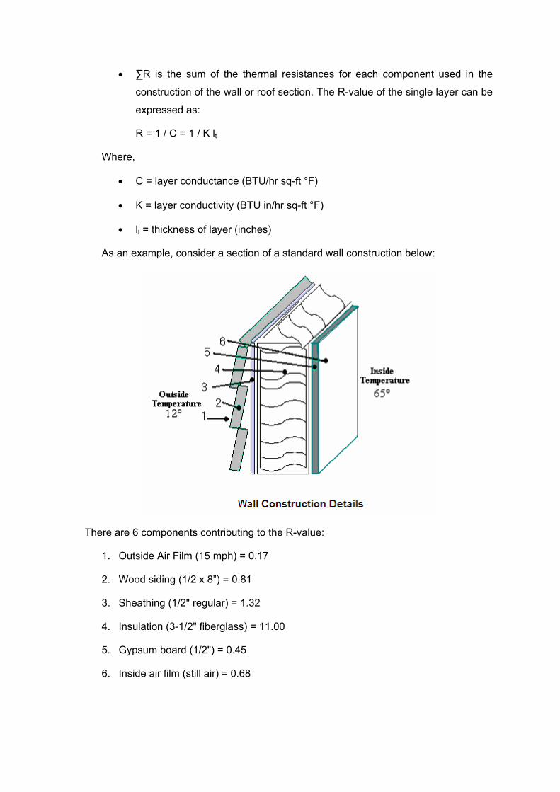
As an example, consider a section of a standard wall construction below:
There are 6 components contributing to the R-value:
1. Outside Air Film (15 mph) = 0.17
2. Wood siding (1/2 x 8”) = 0.81
3. Sheathing (1/2" regular) = 1.32
4. Insulation (3-1/2" fiberglass) = 11.00
5. Gypsum board (1/2") = 0.45
6. Inside air film (still air) = 0.68

Adding the values gives a total resistance, ∑ R = 14.43 (hr-ft2-°F / BTU) and therefore.
U-factor is determined by taking the reciprocal of the R-value, i.e. U = 1/∑ R = 1 / 14.43 =
0.07 BTU / hr-ft2-°F.
The table below lists common construction materials and components with their average
U-Factors.
Material “U” Value
(BTU / hr-ft2-°F)
Glass, single 1.13
Glass, double glazing .70
Single film plastic 1.20
Double film plastic .70
Corrugated FRP panels 1.20
Corrugated polycarbonate 1.20
Plastic structured sheet;
16 mm thick
8 mm thick
6 mm thick
.58
.65
.72
Roof w/o ceiling
With ceiling
Concrete 2 inch thick without insulation
Concrete 2 inch thick with 1” insulation
Concrete 2 inch thick with 2” insulation
0.82
0.25
0.15
0.43
0.20
0.13
Concrete 4 inch thick without insulation
Concrete 4 inch thick with 1” insulation
Concrete 4 inch thick with 2” insulation
0.74
0.23
0.14
0.41
0.19
0.13
Metal deck without insulation
Metal deck with 1” insulation
Metal deck with 2” insulation
0.95
0.24
0.15
0.47
0.20
0.13
Wood 1” thick without insulation 0.50 0.32

Walls No interior finish
Plaster surface
Corrugated iron on wood or metal frame 1.60 0.75
Transite, 3/8” thick on wood or metal frame 1.18 0.35
8 inch solid brick 0.48 0.45
12” solid brick 0.35 0.34
Note - Many insulating materials are rated based on “R” factors. To determine “U” factor
from “R” factor simply divide 1 by R (1/R=U). Conversely, to convert U to R divide 1 by U
(1/U=R).
Heat loss from floors on slab
A substantial amount of heat energy is lost out of the perimeter of a space through the
ground below the perimeter walls and ends. The slab heat loss is calculated by:
Q = F x P x (Ti -Tg)
Where,
• Q = total hourly rate of heat loss in BTUH
• F is the heat loss coefficient for the particular construction and is a function of the
degree days of heating; (unit - BTU/hr-ft2-°F)
• P is the perimeter of slab in ft
• Ti is the inside temperature in °F
• Tg is the ground temperature in °F
Note that the heat loss from slab-on-grade foundations is a function of the slab perimeter
rather than the floor area. For a concrete slab-on-grade floor, the thermal resistance to
heat loss into the ground is close to an R-value of 10 hr-ft2-°F/BTU (or F = 1 / 10 = 0.1
BTU/hr-ft2-°F), and the ground temperature is fairly constant at about 45°F in the winter
(65 - 45 = 20°F).
Perimetric heat loss is conductive heat loss that can be minimized by insulation below
the frost line.

Infiltration Load
Wind pressure outside of a building continually forces a certain amount of air to infiltrate
through openings around doors and windows. Additional air rushes in each time a
window or door opens. This cold air must be included as part of the heat load and extra
equipment capacity must be added to accommodate this extra load. The formula to be
used is:
Q = mass flow (lb/hr) x specific heat (BTU/lb/deg F) x ∆T (F)
To convert from mass flow to CFM, you need to multiply by density and by 60 mins/hr.
Q = volumetric flow (cubic feet/min) x 60 mins/hr x 0.075 lb/cubic foot x 0.24 BTU/lb/F x
∆T (F)
Q = CFM X 1 .08 X ∆T
Where,
• Q = total hourly rate of heat loss in BTUH
• CFM = outside air that enters, in cubic feet per minute
• 1.08 = a constant
• ∆T = temperature difference between inside and outside, °F
The rate of air infiltration is difficult to determine. For calculation purposes it can be
estimated by using what is known as the “air change” method:
R = V x C x 1/60
Where,
• R = infiltration rate in cubic feet per minute
• V = room volume in cubic feet
• C = air changes per hour
Air changes are based on judgment, previous experience, and empirical data. A very
tight building will lose about 0.5 air changes per hour; an average building is about 1.0
air change per hour; and a leaky older space can lose well over 2.0 air changes per
hour.
When specific data and information are not available, infiltration may be assumed to
average one air change per hour.
Ventilation Load
To expel smoke and odors, and to provide general ventilation, it is sometimes desirable
to introduce outside air with a fan or blower rather than rely on air to “leak in”. Often this
forced air ventilation is required by local codes; especially in spaces that are used for
public purposes. It is also necessary to provide for the amount of air that is deliberately
exhausted from spaces like washrooms, kitchens, spray booths, laundry rooms, etc.
When ducts bring outside air in directly to the intake side of a heater, this additional heat
load must be figured into the overall determination of total heat capacity required.
Recommended summer ventilation rates vary but a common accepted rate is 8 cubic
feet per minute (CFM) per square foot of floor space. Winter recommended ventilation
rates are 1.5 CFM per sq-ft of floor space.
The formula for calculating ventilation load is:
Q = CFM X 1 .085 X ∆T
Where,
• Q = total hourly rate of heat loss in BTUH
• CFM = outside air brought in through the system, cubic feet per minute
• ∆T = temperature difference between inside and outside air, °F
• 1,085 = a constant
Note: Both the ventilation load and the infiltration load should be calculated but only the
greater of the two should be included in the total heat-load estimate. In applying unit
heaters for general applications, many contractors allow about 10% of total air quantity
from outside air.
Heating Degree Days & Annual Heat Loss
When you use fuel or electricity for space heating, demand will tend to vary according to
how cold the weather is. The heating degree-day (HDD) concept is used to determine
the coldness of a climate and reflects the demand for energy needed to heat a building.
When the outside air is above a certain temperature your building won't need heating.
This is what is called the 'base temperature' and in the US it's common to assume a
value of 65°F. If the average outside air temperature on a given day is below this base
temperature, you will need heat; and your heat requirement that day will be in proportion
to the temperature deficit in degrees. For example, if the day's average temperature is

50°F, its HDD is 15 (65 – 50). If every day in a 30-day month had an average
temperature of 50°F, the month's HDD value would be 450 (15 x 30).
Degree-day values are available from the U. S. Weather Bureau and the Canadian
Meteorological Division, Department of Transport.
The yearly total of degree-day values for a given locality can be used to calculate a
building’s heat loss for an entire season with the following formula:
H = 24 x Q x D ÷ ∆T
Where,
• H = heat loss in BTUs per heating season
• D = total number of degree days in season
• ∆T = the design temperature difference between indoor and outdoor
temperatures
• Q = design heat loss in BTU/hr
The degree day method is probably the best way to estimate the annual heat loss and
the building’s fuel requirements. For example, Pittsburgh, PA, Columbus, Ohio, and
Denver, Colorado have comparable annual degree days (about 6000 DD/year). It can be
expected that the same structure in all three locations would have about the same
heating bill. Move the building to Great Falls, MT (7800 DD/year), it would have a higher
heating bill; but in Albuquerque, NM, (4400 DD/year), it would have a relatively lower
heating cost.
From the above data, we can make an educated guess about the annual heat loss.
How?
To determine the annual heat loss, divide the energy loss rate by the design temperature
difference and then multiply it by 24 hours per day and the number of annual degree
days (from the weather files for a particular location). For example, a house with a design
heating load of 30,000 BTU/hr in Pittsburgh (outdoor design temperature of 4°F) will use:
[30,000 BTU/hr x 24 hr/day / (65-4) (°F)] x 6000 DD/yr = 71 million BTU/yr.
SECTION - 2 APPLICATION CONSIDERATIONS – FUEL CHOICES
In this section, we will examine:
1. The common heating fuels
2. Factors influencing the choice of heating fuel
3. Heat value of various fuels
4. Heating systems ranking
Common Heating Fuels
The most common fuels used for space heating are natural gas, propane, fuel oil and
electricity.
The most frequently used unit of measurement for the energy content of the fuel is
British Thermal Unit (BTU). One BTU is equal to the amount of energy it takes to raise
the temperature of one pound of water by 1 degree Fahrenheit.
1. Natural Gas: Natural gas is the most prevalent fuel medium of space heating
today in the United States. Natural gas delivered for heating purposes typically
has a heating value between 800 and 1150 BTUs per cubic foot. The heating
value is an important piece of information for:
• Sizing a heater or furnace and the gas-supply piping for it;
• Estimating gas consumption and the cost of operation.
Most gas heating appliances have heating capacities of between 40,000 and
150,000 BTUH.
1. Propane: Propane, or liquefied petroleum gas (LPG), can be used in many of the
same types of equipment as natural gas. It is stored as a liquid in a tank, so it can
be used anywhere, even in areas where natural gas hook-ups are not available.
Consumption of propane is usually measured in gallons; propane has an energy
content of about 92,700 BTU per gallon.
2. Fuel Oil: Several grades of fuel oil are produced having heating capacities
varying between 56,000 and 150,000 BTU/hr. One gallon of gasoline contains
about 124,000 BTU.
3. Electricity: The heating capacity of electric systems is usually expressed in
kilowatts (kW). A kilowatt-hour (kWh) is the amount of electrical energy supplied
by 1 kW of power over a 1-hour period. 1 kW of electric heating produces 3,413
BTU’s of heat per hour.

Each of the heating options have pluses and minuses. Depending on the level of comfort
and the operating costs, it’s simply a matter of applying the best judgment to provide a
safe and reliable system that will maintain a constant, comfortable indoor environment
under all outdoor conditions.
Factors Influencing the Choice of Heating Fuel
Selecting the fuel and heating system best suited for your needs depends on many
factors. These include: the cost and availability of the fuel or energy source; the type of
appliance used to convert that fuel to heat and how the heat is distributed in your space;
the cost to purchase, install, and maintain the heating appliance; the heating appliance's
and heat delivery system's efficiency; and the environmental impacts associated with the
heating fuel. Heating system design is often compromised by the first cost of equipment
and the recurring fuel costs needed for operation. This should not be the sole measure
for selecting a heating system. The broad comparisons on the choice should be based
on various other system characteristics such as equipment efficiency, fuel source
availability, required system capacity, fuel energy content in millions BTU per unit,
environmental impact and heat response or recovery.
A brief description of fuel and heating system selection factors is discussed below:
1) Fuel Availability - The first step in the process of selecting space heating equipment
involves determining the fuel to be used. Obviously, if only one fuel is available, no
decision is necessary. If several fuels are available and one is natural gas, the choice
is made simpler because natural gas offers the best combination of ready availability,
reliability, continuity of supply, low cost, non-polluting combustion, and good control
for accurate uniform heating. Where pipeline natural gas is not available, propane
makes a sound alternative choice; it is a clean-burning, nonpolluting and controllable
as natural gas. Although its cost may be higher on a per cubic-foot basis, propane
has a higher heating value and is competitive on a per-BTU basis.
2) Equipment costs not only vary between heating systems, but can also vary
significantly within the same class of equipment depending on the size and efficiency.
In many cases, the extra cost of more efficient models can be recovered in three to
five years due to energy savings. Most experts agree that higher first costs are
justified if the energy efficiency investments yield payback within five years. This
means if you pay an extra $500 for a more efficient model, you should save $500 in
energy costs within five years to make it worthwhile. This means approximately 20%
simple return on your investment. As utility costs increase, so will the return on your
investment.

3) Price of fuel: This is not always easy to do without some help. You will need to know
what your heating costs were for the last several years for the fuel you were using
and compare that with the cost of the alternative fuel over the same period. Local
consumer agencies should be able to help here.
4) Comfort: Comfort is defined by uniformity, heat response control and noise levels. A
comfortable heating system may incorporate some radiant heating as well as
convective. It may be difficult to obtain comfort levels if a purely radiant system is
used (such as radiant panels) so a mixture of convective and radiant heating is
desirable.
• To maintain adequate comfort conditions, a controllable heating system is
necessary (e.g. automatic thermostatic controls on oil or gas-fired system or
electrical heating system). Note that a solid fuel system cannot be easily
controlled.
• Heat Response factor means how quickly the system will supply heat to the
space. A heating system with a good "heat response" time brings a room up
to the human comfort zone more quickly. A convective heater has a quicker
heat response when compared to the radiant heaters.
• If noise levels in a room such as a library are to be at a minimum, then fan
convectors are not a good option. Quieter form of heating options includes
radiators, under-floor heating, natural convectors or a radiant ceiling.
5) Occupancy – A number of questions need to be answered about how the space to
be heated is occupied and used. How many hours per day and how many days per
week do people regularly use the space? Do the people usually sit (e.g. office) or do
they engage in heavy physical work (factory)? Does the space store materials that
are perishable? Does the space to be heated include sleeping quarters? (Equipment
certified to ANSI Z83 must not be used to heat any space where people sleep.)
Answers to these questions will determine what equipment to use, what temperature
should be maintained and how much temperature variation is tolerable.
6) Application and Type of Building: There are many types of buildings each having
a different application. Here are few notes that require the attention of architect,
engineer or heating system designer:
• In some applications (e.g., theaters and churches), noise and vibration control
are primary considerations.

• In other buildings (refineries, chemicals or spray paint booths), explosion
prevention may be the primary consideration.
• In textile facilities fire is the major concern and in food facilities, the need for
hygiene conditions can eliminate several options.
• Hospitals require clean environment; thus, filtered air heating may be necessary,
usually in a full air conditioning system.
• For warehouses, radiant heating may be a suitable option since the air
temperature need not be high.
• Museums and Archive Stores require constant control of room temperature and
humidity - air-conditioning may be necessary.
• In some buildings it is difficult to run services through (e.g. stone walls, solid
concrete slabs); therefore, electrical heating may be used.
• In some buildings like nursery schools and nursing spaces, if radiators are
utilized, it is advisable that low surface temperature radiators are used.
• In wet areas like shower rooms and bathrooms, under-floor heating has an
advantage in that it keeps the floor dry.
• Some buildings (like churches) may be intermittently used so electrical heating
may not be completely ruled out. High temperature roof mounted quartz electric
heaters have been used in this type of building.
• Schools have limited wall space so under-floor heating or low temperature ceiling
heating is sometimes used.
• In general, large areas benefit from the quick warm-up of air heating. In buildings
with large occupancy, a ventilation system may be necessary to provide
adequate fresh air for occupants, e.g. concert hall, auditoria. Ventilation systems
with ductwork require ceiling void space.
7) Plant Space: Room for plant and equipment, storage space for fuel, etc. are some of
the considerations for selection of heating systems. While natural gas may be piped
and electricity lines are fixed, space is required for storing the fuel oil and solid fuels.
A decision needs to be made on putting the central heating unit in the basement if
the unit is not prone to flooding or rooftop unit (RTU) if the noise level below is not an
issue. A factory assembled RTU is the cheaper option, which provides better quality
control, does not require valuable building floor space, and provides direct access to
interior spaces via the ceiling plenum.
In very large facilities, all utility equipment such as an air-conditioning plant, heating
and cooling equipment, emergency electrical generator, fire safety systems, and
often electrical supply transformers, Motor Control Centers (MCC) and Lighting
Control Centers (LCC) can be located in a remote mechanical room. This allows for a
better central management of the system operation, but is more expensive to build.
8) Let Buildings: Most landlords prefer the tenant to look after payment of their own
heating bills. Individual meters for gas or electricity in a block of flats means that the
tenants are responsible for the payment of bills. In a large office building with several
tenants, electrical or natural gas heating is easy to measure in zones. Hot water
heating system is cumbersome to divide. In let buildings, some form of a billing
arrangement needs to be in place to charge tenants. This essentially requires a study
on the quality of available instrumentation, ease of measurement and reliability of
readings.
9) Appearances: In some buildings, the designer may require the heating system to be
totally hidden, e.g. under-floor heating, heated ceiling or air heating. In some
buildings the designer may wish to make a feature of the heating system or heat
emitters, e.g. a warm air ductwork system painted in a bright color or concealed in a
reflected ceiling plan. In some areas, like parametric lengths of building, cast iron
radiators may be the choice. For Rooftop units (RTUs) the designer needs to
integrate the unit into the architectural theme of the building so that it looks like it is
supposed to be there, not just added as an after-thought.
10) Efficiencies of heating equipment are rated by different methods such as the
Heating System Performance Factor (HSPF), Annual Fuel Utilization Efficiency
(AFUE) or Thermal Efficiency/Combustion Efficiency Factor (Et/Ec). In all cases, the
higher the rating number, the more efficient is the unit.
The Federal Energy Agency requires all gas and oil fired furnaces be given operating
efficiency ratings, such as the annual fuel utilization efficiency (AFUE). For
combustion furnaces such as gas or oil, an AFUE rating of 8.1 or higher is
considered good.
For electric resistance heating, although heat is generated almost at 100 percent
efficiency, it is very costly on $ per BTU heat release compared to other options. This
is because first we generate electricity by thermal energy at 35 to 50% efficiency and
than using it again for heating. The high operating cost of electricity must be
considered to get an accurate picture of the system economics.

An efficient method of using electric energy asa heating source is the use of heat
pumps. For air-to-air heat pumps (the heat exchanger is cooled or heated by air), a
rating of 3.2 is considered satisfactory. For water-source heat pumps where the heat
exchanger is heated or cooled by water, a rating of 3.8 is considered good. If rated
by the HSPF method, 6.8 or better is considered satisfactory for heat pumps.
11) Transport Media: Another way of grouping heating systems is by the transport
media used to get the heating energy to the distribution point. Heating fuels are
normally handled in one of the following ways: Some fuels (such as fuel oil in a tank
or coal in a bunker) are stored or warehoused, while other fuels (such as natural gas
or electricity) are point-of-use fuels. Point-of-use fuels are delivered through utility
piping or wiring networks, and are metered and billed after consumption. Stored fuels
are paid for when purchased. Stored fuel suppliers are not regulated as closely or
carefully compared to point of-use fuel suppliers. As a result, prices for stored fuels
tend to fluctuate more widely with market conditions. Point-of-use suppliers are
normally regulated by state agencies and are restricted to rate schedules that tend to
lag the market response of stored fuels. Electricity can be transported directly via
wires.
12) Environmental impact: This factor considers air pollution and the best use of
resources. The products of combustion of oil, coal and gas pollute the atmosphere.
• Coal is probably the worst offender since carbon dioxide contributes to the
greenhouse effect and sulphur dioxide causes acid rain. Smoke causes urban
smog and soot and ash adds to the problem. Oil produces contaminants to a
lesser extent and gas is probably the best of the three.
• Using electricity is of little benefit because power stations burn fuel to produce
electricity. For example, to generate one kilowatt hour of electricity in a coal-fired
plant will require burning one pound of coal. This produces about three pounds of
carbon dioxide (a greenhouse gas) and four ounces of sulfur dioxide (which
contributes to acid rain).
• A totally 'green' source of heat may be solar energy if you live in an area with
plenty of sunshine.
13) Safety: Ensure all apparatus is approved and meets standards and regulations. You
should be aware of the following hazards when considering a heating system:
• Fires and burns caused by contact with or close proximity to the flame, heating
element, or hot surface area.
• Poor safety record of some open gas and coal fires as well as paraffin heaters.
• Fires and explosions caused by flammable fuels or defective wiring.
• Indoor air pollution caused by improper venting or incomplete combustion of fuel-
burning equipment.
• Carbon monoxide poisoning caused by improper venting of fuel-burning
equipment
14) Security of Supply of Heat Source: Some fuels at certain times may be liable to
unsecured supply, e.g. oil prices can fluctuate. It may be advisable to have a dual
fuel system so that burners can easily be changed over to burn the cheaper or more
readily available fuel.
Alternative sources of energy are not always secure, e.g. the wind doesn't always
blow on a wind farm. The sun doesn’t always shine if the system relies on solar
panels. A hybrid system is more secure, otherwise back-up boilers can be used.
15) Fluctuating Heat Demand: In some buildings the demand for heat fluctuates widely
throughout the day. To meet this demand economically, a modular system such as
multiple unit heaters or electrical units may be a good option. This means that the
required number of boilers is automatically switched on to meet the demand.
16) Industrial Waste Heat: In some industrial units, heat is available from the process,
e.g. condensate, a by-product of steam or high temperature exhaust flue gases.
Waste heat recovery equipment could be utilized to generate hot water or steam,
which can be used to warm air in a heat exchanger. There are many ways in which
waste heat can be utilized to pre-heat water or upgrade in heat pumps for further use
in space heating.
17) Maintenance: Maintenance is very important with the heating systems because
there are many pieces of equipment that can cause problems. With fuel fired
equipment, the heat exchanger surfaces have to be cleaned and the burner has to be
maintained and adjusted. In case of a hot water system, the water quality needs to
be assured to prevent scaling. The electrical system does not have such problems
other than routine switchgear maintenance.
18) Financial Rebates/Subsidies: Some gas and electric utilities offer rebates or low
interest loans if certain systems are installed. Electric utilities prefer high efficiency
heat pumps using heat recovery units to improve water heating. Gas utilities prefer
efficient combinations of gas space and water heating systems. If rebates or low
interest loans are offered, it could make the "equipment cost" factor more favorable.

Heating Values
The term “heating value” refers to the amount of heat generated by burning fuel
completely. Heating value is expressed in energy per unit of the substance, usually
mass, such as: BTU/lb, BTU/gallon, BTU/ton or BTU/kWh.
The table below provides a list of typical heating fuels and the BTU content in the units
that they are typically sold in the United States. The figures below are for guidance only;
commercial and industrial users should obtain more precise values from their fuel
vendors. The exact heating value for a specific gas can be obtained from the supplying
utility.
Average BTU Content of Fuels
Fuel Type No. of BTU/Unit
#2 Fuel Oil 140,000/gallon
#6 Fuel Oil 150,500 /gallon
Diesel 137,750/gallon
Kerosene 134,000/gallon
Electricity 3,412 per kWh
Natural Gas* 850,000 - 1,150,000/thousand cubic feet
Propane 91,330/gallon
Wood (air dried) * 20,000,000/cord or 8,000/pound
Pellets (for pellet stoves; premium) 16,500,000/ton
Kerosene 135,000/gallon
Coal 28,000,000/ton
Note that the energy content values may vary drastically, especially for wood and coal.
As an energy system designer, you must learn the purchasing units associated with each
energy source. Rounding things off can make it a little bit easier. For example, natural
gas contains about 1000 BTU per cubic foot. So, one hundred cubic feet (CCF) contains
about 100,000 BTU. A gallon of fuel oil delivers almost 100,000 BTU per gallon. Knowing
the unit efficiency allows you to calculate the original content.
Heating Values - A More Detailed Discussion
The heating values provided in the table above are the "higher" or "gross" heating values
of the fuels as estimated by the Energy Information Administration in the Annual Energy
Review 2001.
“Higher (or gross)” heating values are commonly used in energy calculations in the
United States. "Net" or "lower" heating values may also be used. The difference between
the two values is the amount of energy that is necessary to vaporize water that is
contained in the fuel or created in the combustion process when hydrogen in the fuel is
combined with oxygen to form water vapor. In general, this difference can range from as
little as 2 percent to as much as 60 percent, depending on the hydrogen or moisture
content of specific fuels. The heat energy contained in the water vapor is generally lost
as the combustion gases leave the appliance vent or chimney. Some types of
combustion appliances, however, such as high efficiency "condensing" forced-air
furnaces, are able to capture much of the heat contained in the water vapor before it
leaves the furnace vent (thus the term "condensing"). Since electricity is not burned in a
heating appliance, the two values are equal.
*Natural gas is the most common space heating fuel and typically has a heating value
somewhere between 800 and 1150 BTUs per cubic foot. The heating values show
considerable variation for several reasons. First, natural gas from different sources can
contain different proportions of methane, ethane, propane, and butane. The more carbon
and hydrogen atoms there are in a molecule of gas, the greater its heating value. This
means that, as the percentage of ethane, propane, and butane increases, the heating
value increases. Second, natural gas may contain varying amounts of nitrogen; an inert
gas that does not burn at all. The greater the amount of nitrogen present, the lower the
heating value will be.
*Wood heating values can vary significantly. The most important factor affecting useful
BTU content is the moisture content of the wood. Well-seasoned, air-dried wood will
typically have a moisture content of around 20 percent (when compared to a "bone dry"
sample of the wood). A very rough approximation of the effect of moisture content on the
heating value is for every percent increase in moisture content (relative to a bone-dry
sample), there is a one percent decrease in the heating value.

How to equate the heaters to the heating values?
For heating equipment to do its job, it must receive the necessary number of BTUs per
hour. This required BTUH input rate usually appears on the nameplate of the device. It
can be converted to fuel input rate (say gas flow rate) by using the heating value
(obtainable form the supplying utility) and the following formula:
R = I ÷ H
Where:
• R = gas flow rate in cubic feet per hour;
• I = input rate in BTUs per hour;
• H = heating value of gas in BTUs per cubic foot.
Example calculation:
A heater with an input rating of 150,000 BTUs per hour is to be supplied with gas having
a heat value of 1000 BTUs per cubic foot. The heater will use approximately 150 cubic
feet of natural gas per hour (150,000÷1000 = 150).
How to equate the fuels based on heating values?
The average BTU content of fuel values make comparisons of fuel types possible. For
example:
The heat content of one gallon of fuel oil #2 having a heat value of 140000 BTU’s
roughly equals that of 41 kWh of electricity, 137 cubic feet of natural gas, 1.5 gallons of
propane, 17.5 pounds of air-dried wood, 17 pounds of pellets, a gallon of kerosene, or 10
pounds of coal.
One million BTU is the heat equivalent of approximately 7 gallons of No. 2 heating oil or
kerosene, 293 kWh of electricity, 976 cubic feet of natural gas, 11 gallons of propane,
125 pounds of air-dried wood, 121 pounds of pellets, or 71 pounds of coal.
The efficiency of the heating appliance is an important factor when determining the cost
of a given amount of heat. In general, the efficiency is determined by measuring how well
an appliance turns fuel into useful heat. (The condition of the heat distribution or delivery
system also affects the overall system efficiency.) Many types of space heating
appliances must meet minimum standards for efficiency developed by the U.S.
Department of Energy. The table below provides average efficiencies for common
heating appliances.

Estimated Average Fuel Conversion Efficiency of Common Heating Appliances
Fuel Type - Heating Equipment Efficiency (%) Coal (bituminous) Central heating, hand-fired 45.0 Central heating, stoker-fired 60.0 Water heating, pot stove (50 gal.) 14.5 Oil Cast iron head burner 60.0 Flame retention head burner 70 - 78 High static replacement burner 75 - 82 New standard furnace 78 - 86 Mid efficiency furnace 83 -89 High efficiency condensing furnace 85 - 95 Typical central heating 80 -85 Water heater (50 gal.) 60 Gas Conventional furnace 60.0 Vent damper with non-continuous pilot light 62 - 67 Mid efficiency furnace 78 -84 High efficiency condensing furnace 89 - 97 Typical central boiler 85.0 Minimum efficiency central furnace 78.0 Room heater, unvented note 1 99.0 Room heater, vented note 1 65.0 Water heater (50 gal.) 62.0 Electricity Baseboard, resistance 100 Central heating, electric furnace-forced air 100 Central heating, air source heat pump note 2 200+ Central heating, ground source heat pump note 2 300+ Wood & Pellets Franklin stoves 30.0 - 40.0 Stoves with circulating fans 40.0 - 70.0 Catalytic stoves 65.0 - 75.0 Pellet stoves 85.0 - 90.0
Note 1*: Most of the appliance efficiencies given in the table above roughly account for
the net heating value of fuels used in a vented appliance (i.e. one that has a chimney).
An un-vented space heater, such as a kerosene heater or a natural gas fireplace insert,
delivers nearly all of the heating value of a fuel to the space in which it is located. It also
puts all the products of combustion including carbon dioxide, water vapor, and small
amounts of carbon monoxide, sulfur dioxide, and nitrous oxides into the room. These
types of heating units generally require that a window be opened (slightly) for safe
operation, which reduces their overall heating capability.
Note 2*: Heat pumps are measured by coefficient of performance (COP). A COP of 1.5
means that the equipment has an efficiency of 150%. It can be over 100% because heat
pumps move heat from outside to inside, instead of creating it.
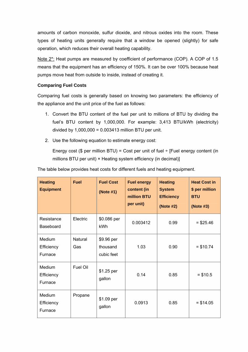
Comparing Fuel Costs
Comparing fuel costs is generally based on knowing two parameters: the efficiency of
the appliance and the unit price of the fuel as follows:
1. Convert the BTU content of the fuel per unit to millions of BTU by dividing the
fuel’s BTU content by 1,000,000. For example: 3,413 BTU/kWh (electricity)
divided by 1,000,000 = 0.003413 million BTU per unit.
2. Use the following equation to estimate energy cost:
Energy cost ($ per million BTU) = Cost per unit of fuel ÷ [Fuel energy content (in
millions BTU per unit) × Heating system efficiency (in decimal)]
The table below provides heat costs for different fuels and heating equipment.
Heating Equipment
Fuel Fuel Cost
(Note #1)
Fuel energy content (in million BTU per unit)
Heating System Efficiency
(Note #2)
Heat Cost in $ per million BTU
(Note #3)
Resistance
Baseboard
Electric $0.086 per
kWh 0.003412 0.99 = $25.46
Medium
Efficiency
Furnace
Natural
Gas
$9.96 per
thousand
cubic feet
1.03 0.90 = $10.74
Medium
Efficiency
Furnace
Fuel Oil $1.25 per
gallon 0.14 0.85 = $10.5
Medium
Efficiency
Furnace
Propane $1.09 per
gallon 0.0913 0.85 = $14.05

Note #1: The fuel costs used are the national annual average residential fuel prices in
2007 according to the Energy Information Administration (EIA), U.S. Department of
Energy. Prices will vary by location and season.
Note #2: The system efficiencies used are assumed examples only.
Note #3: Energy cost ($ per million BTU) = Cost per unit of fuel ÷ [Fuel energy content (in
millions BTU per unit) × Heating system efficiency (in decimal)]
Rule of Thumb Estimation of Annual Heating Cost
To convert BTU/yr values into dollars per year for the annual heating cost, we have to
check how much energy costs. Again these values vary widely, depending on the
season, geographic location and type of fuel. This assumption is too general to use for
making large economic decisions, but it is certainly easier than trying to keep up with
these constantly changing values.
For simplicity, consider all energy will cost exactly $10 per million BTU. At today's energy
prices, this average value is high for gas heat (by about a factor of 2), about right for fuel
oil, and low for electric resistance heat (by about a factor of 2). The reason for this is
that natural gas, for all practical purposes, is a raw commodity, while electricity is a
value-added commodity. In other words, electricity is generated by raw commodities,
including natural gas.
Even these prices vary substantially across the nation. Natural gas in New York sells for
almost three times the price in Colorado and Louisiana. Electricity on Long Island costs
almost ten times more than the price that Bonneville Power Administration gets for their
hydroelectric power in Montana.
So in the Pittsburgh example we have discussed earlier (refer to Part 1, heating degree
days) using 71 million BTU/yr, we would calculate the heating cost to be 71 x $10 = $710
per year. But in reality the heating cost might range from under $350 for gas heat to over
$1400 for electric resistance heat.
Heating Fuels Ranking
The heating systems are ranked based on survey ratings from a group of design
professionals, facility managers and contractors. In determining the overall rank of
various systems, more weight is given to the "efficiency and fuel cost" factor.

The table below may serve as a decision-making guide.
Heating System Equipment Cost
Efficiency & Fuel Cost
Environment Impact
Heat Response
Overall Rank
Natural Gas 4 1-3 2 1 1
Heat Pump (Air to
Air) 7 2-4 4 9 2
Heat Pump (Water
Source,
Geothermal)
10 1-3 4 6 3
Heating Oil 5 2-5 5 1 4
LPG
(Propane/Butane) 4 8 4 1 5
Wood Stoves 4-8 2-6 2-4 4 6
Wood Fireplaces 7 5-10 6-10 5-8 7
Electric Resistance
(Strip) 3 10 10 3 8
# Rating Scale: 1 = best value or condition; 10 = poorest value or condition
1) Ranked first are the natural gas heating systems:
The natural gas heating systems are the most effective systems where they are
available. The natural gas systems have high efficiencies, low fuel costs, low
environmental impacts, quick heat response, and moderate equipment costs and are
relatively safe. They are clean burning, easy to use, and often the lowest cost per
delivered energy. More efficient models have electronic ignitions as opposed to pilot
lights. Natural gas is the most popular heating source for locations where it is
available.

2) Ranked second are the air to air heat pump systems:
Air to air heat pump systems are generally efficient to operate, but initial equipment
cost is usually higher and heat response is slow. A heat recovery unit can be added
to improve the performance of the water heater. Where resistance costs more than
fuel fired systems on a BTU-for-BTU basis, heat pumps may be a more cost-effective
alternative, especially where heat pumps can also provide space cooling,
dehumidification, or recover building or waste-water waste heat. The drawback is that
the heat pump units are least efficient when outdoor is coldest and sometimes a
standby electric resistance heating is added for such periods.
3) Ranked third are the geothermal heat pump systems:
Water source or geothermal heat pump systems use heat exchangers to recover
heat from or release heat to ground water or earth. Systems using pumped well
water may not be allowed in some water districts and may have scaling problems.
The cost of these systems is generally highest, but comparable to natural gas in
terms of efficiency and cost effectiveness to operate. Environmental impact is
moderate; heat response is usually better than air to air heat pumps.
4) Ranked fourth are the fuel oil systems:
Fuel oil heating systems have moderately high efficiencies, moderate initial costs,
relatively high environmental impact, and high heat recovery response. Fuel oil
shares many of the same characteristics as gas, but requires on-site storage of fuel
and a fuel unloading site. These deliver warm comfortable heat to spaces and are
available in up-flow, down-flow and horizontal configurations.
5) Ranked fifth are the liquefied petroleum gas systems:
Liquid petroleum gas systems, such as propane and butane, have a moderately low
initial cost, relatively high fuel cost, moderate environmental impact and high heat
response. In general, the same technologies and comments apply to propane as to
natural gas, with slight differences in the efficiencies. Propane has a lower hydrogen
level than natural gas. About 3% less energy is tied up in the form of latent heat with
propane systems than with natural gas. This means that conventional and mid-
efficiency propane furnaces can be expected to be slightly more efficient than
comparable natural gas units. On the other hand, propane's lower hydrogen content
makes it more difficult to condense the combustion products, so that propane-fired
condensing furnaces will be 2-3% less efficient than the same unit fired with natural
gas. While all current heating equipment has built-in safety features and are installed
to rigid code requirements, LPG systems are less safe than others as this gas is
heavier than air.
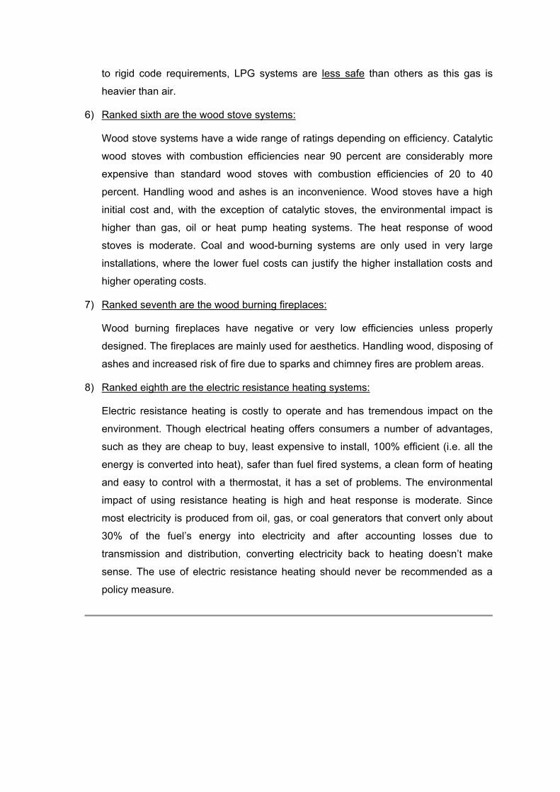
6) Ranked sixth are the wood stove systems:
Wood stove systems have a wide range of ratings depending on efficiency. Catalytic
wood stoves with combustion efficiencies near 90 percent are considerably more
expensive than standard wood stoves with combustion efficiencies of 20 to 40
percent. Handling wood and ashes is an inconvenience. Wood stoves have a high
initial cost and, with the exception of catalytic stoves, the environmental impact is
higher than gas, oil or heat pump heating systems. The heat response of wood
stoves is moderate. Coal and wood-burning systems are only used in very large
installations, where the lower fuel costs can justify the higher installation costs and
higher operating costs.
7) Ranked seventh are the wood burning fireplaces:
Wood burning fireplaces have negative or very low efficiencies unless properly
designed. The fireplaces are mainly used for aesthetics. Handling wood, disposing of
ashes and increased risk of fire due to sparks and chimney fires are problem areas.
8) Ranked eighth are the electric resistance heating systems:
Electric resistance heating is costly to operate and has tremendous impact on the
environment. Though electrical heating offers consumers a number of advantages,
such as they are cheap to buy, least expensive to install, 100% efficient (i.e. all the
energy is converted into heat), safer than fuel fired systems, a clean form of heating
and easy to control with a thermostat, it has a set of problems. The environmental
impact of using resistance heating is high and heat response is moderate. Since
most electricity is produced from oil, gas, or coal generators that convert only about
30% of the fuel’s energy into electricity and after accounting losses due to
transmission and distribution, converting electricity back to heating doesn’t make
sense. The use of electric resistance heating should never be recommended as a
policy measure.
SECTION - 3 TYPES OF HEATING SYSTEMS
There are almost endless variations and combinations of equipment that can be utilized
to create the best system. Every type of heating equipment has its strength and
limitations. Depending on the level of comfort and the operating costs, you’ll need to
choose the style of system that integrates best with your facility requirements. It’s simply
a matter of determining your requirements and researching the best options with expert
design professionals.
In this section, we will examine:
1. The heating methods
2. Types of heating systems
3. Types of heat distribution systems
4. System design decisions - central or zoned systems
THE HEATING METHODS
Space heating engineers are usually interested in distributing heat throughout the space
of a building or enclosure. Most forms of space heating fall into either Radiant or
Convective heating. Both these methods are effective in space heating and; therefore, it
is important to understand the basic fundamentals.
Radiant Heating
Radiant heating systems utilize infra red radiation to heat objects, people and surfaces.
Anyone who has warmed themselves by a hot wood stove or warmed their hands at a
camp fire has experienced radiant heat. It is also demonstrated by standing in the sun on
a winter’s day; or walking near a brick wall that has been exposed to the sun during the
day. In both examples, although the air may not be warm, you are able to feel the heat
energy radiating from these surfaces.
Radiant heat directly heats objects in the room, but does not directly warm the room air.
These are appropriate, if your rooms have large open spaces or high ceilings, or are
particularly draughty.
Advantages of Radiant Heating
• Heat can be applied only to the area required.
• No air movement is caused by the system itself, therefore unwelcome draughts
are minimized and dust movement is reduced.
• Because of radiant heat transfer, vertical temperature stratification is reduced.

• Lower operating costs should be achieved because of the localization of heating
compared to convection systems.
Disadvantages
• An unobstructed space above floor level is necessary for an effective installation.
The presence of ductwork, pipes, overheard conveyors and other equipment may
sometimes limit full utilization of radiant heating.
• In certain applications where minimum ventilation rates is critical, a combination
of convection heating (or the ventilation of intake air) and radiant heating is
required.
Convective Heating
Convective utilizes air circulation to transfer heat and involves two basic principles: a)
cold air displaces warm air; and b) warm air rises in the presence of cold air. These are
either free or forced type.
• Natural Convection systems rely on the buoyancy of heated air to provide
circulation throughout the space. The most common examples are the steam
radiator and the baseboard unit.
• Forced Convection systems have a fan to force the air to circulate. Unit heaters
and other fan/coil units are the common examples. These units allow the
introduction of outside air and provide air filtration.
To maximize efficient use of the heat energy, it is important to force the mixing and
circulation of these warm air layers.
The Advantages of Convective Heating:
• Convectors are used to heat up spaces more quickly than radiators.
• The convective units ensure that warm air is evenly distributed throughout the
structure.
Disadvantages:
• The air heaters attempt to heat the entire space including people, hardware and
all of the air within the space.
• The high discharge air volumes can cause unwelcome draughts which may
reduce the perceived heating effect.

• Because of their usual overhead location severe vertical temperature stratification
can occur with ceiling temperatures as much as 30°C above floor temperature.
• High volume air movement can also cause dust problems which could affect
product quality particularly in product coating operations.
Convection heaters are appropriate if your space is insulated, well sealed against
draughts and have average ceiling heights. They should be avoided in draughty rooms,
rooms with high ceilings or areas with open stairwells. Convective heating is typically the
most common form of heating in majority of facilities.
TYPES OF HEATING EQUIPMENT
There are two broad classification of heating equipment:
1. Combustion equipment, where heat is generated by the combustion of fuel in a
furnace under careful air/fuel control. The heat of combustion is recovered in some
form of integral heat exchanger and is distributed via a supply air ductwork. Another
form of combustion equipment is the boiler, which provides heat through a hydronic
distribution system (hydronic systems are also referred to as hot water systems).
2. Electric equipment, where the space heaters supply heat through an electric
resistance element that convert electricity to heat with almost 100 percent efficiency.
Another form is a heat pump, which extracts heat from the air, ground or water and
usually delivers it through a forced air distribution system.
Efficiency Terminology
When shopping for heating equipment, it is important that you understand the common
terminology used to describe different types of equipment. There are several types of
efficiency terms used when describing heating equipment. The most common terms
used to describe heating equipment are as follows:
1. Combustion Efficiency: This term is the most basic description of efficiency. It
denotes the percentage of fuel burned and turned into heating energy.
2. Thermal Efficiency: This term is a measurement of the actual amount of
available energy that transfers into the heating medium. It is derived by operating
a piece of equipment at a steady state and measuring how much fuel is used vs.
how much useable heat comes out. It is most typically used in reference to
boilers.
3. Distribution Efficiency: This is the measure of efficiency of how well the heating
equipment actually delivers the heat energy (BTUs) to your space and structure.
This expression addresses how energy is distributed and transferred to the
objects requiring heat.
Distribution efficiency is greatly affected by the system(s) you select, and how
you utilize your equipment. Some examples:
a. Forced hot air systems’ distribution efficiency is largely dependent upon the
means of air circulation used in the space.
b. Infrared systems, properly installed, can transfer heating energy very well to
crops without the necessity of air circulation.
c. With hot water, distribution efficiency is affected tremendously if the supply
and return lines are poorly installed or are not insulated.
d. Some hot water systems deliver heat much more efficiently than others.
Finned pipes heat faster than bare pipes.
e. With hot water, a high efficiency distribution system coupled to a poor
efficiency boiler may be better than a high efficiency boiler with poor efficiency
distribution.
Look at all facets of heating system efficiency when making heating equipment
purchases along with other selection factors.
DISTRIBUTION SYSTEMS
There are three types of distribution systems.
1. A forced air system circulates warmed or cooled air around the house through a
network of ducts. It also provides a means of distributing ventilation air.
2. Space heaters, though not technically a distribution system, provide direct heat to
the room in which they are located.
3. A hot water (hydronic) system distributes heat through hot water pipes and
radiators.
Forced Air Systems
Forced-air (convective) systems also referred to as “a central heating system” in
commercial terminology utilize a series of ducts to distribute the conditioned heated or
cooled air throughout the whole space. The heat source is either a furnace, which burns
a gas, oil or an electric heat pump. Some forced heating systems utilize hot water or
steam as heating source. A blower, located in a unit called an air handler, forces the
conditioned air through the ducts. Unless fresh air is piped in from outside, the system
will re-circulate 100% of the air.
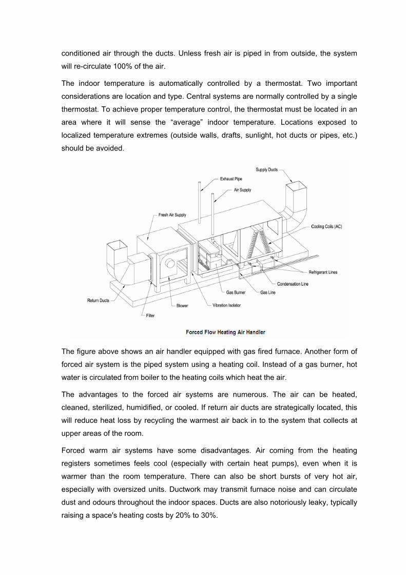
The indoor temperature is automatically controlled by a thermostat. Two important
considerations are location and type. Central systems are normally controlled by a single
thermostat. To achieve proper temperature control, the thermostat must be located in an
area where it will sense the “average” indoor temperature. Locations exposed to
localized temperature extremes (outside walls, drafts, sunlight, hot ducts or pipes, etc.)
should be avoided.
The figure above shows an air handler equipped with gas fired furnace. Another form of
forced air system is the piped system using a heating coil. Instead of a gas burner, hot
water is circulated from boiler to the heating coils which heat the air.
The advantages to the forced air systems are numerous. The air can be heated,
cleaned, sterilized, humidified, or cooled. If return air ducts are strategically located, this
will reduce heat loss by recycling the warmest air back in to the system that collects at
upper areas of the room.
Forced warm air systems have some disadvantages. Air coming from the heating
registers sometimes feels cool (especially with certain heat pumps), even when it is
warmer than the room temperature. There can also be short bursts of very hot air,
especially with oversized units. Ductwork may transmit furnace noise and can circulate
dust and odours throughout the indoor spaces. Ducts are also notoriously leaky, typically
raising a space's heating costs by 20% to 30%.

Types of Forced Air Systems
The most economical and energy efficient central heating systems are either:
1. High efficiency, natural gas ducted heaters;
2. Natural gas hydronic systems;
3. Reversible-cycle heat pump air-conditioning system; or
4. Off-peak electric in-slab heating
When choosing gas systems, look for the energy rating label - the more stars you see,
the better the performance, and the more money you'll save on your energy bill.
The table below compares various central heating systems per 1500 sq-ft space.
Central Heating System (1500 ft2)
Description Approx. purchase/install price
Annual Heating Costs (note 1)*
Ducted natural gas Circulates warm air around the space. $4,000 - $6,000
4-5 star rating: $110-$270
1-2 star rating: $160-$360
Reverse-cycle air conditioner
Circulates warm or cool air around the space.
$8,000 - $12,000 $120-$220
Hydronic Heating
Water is heated in a boiler (fuelled by natural gas, LPG, wood or off-peak tariff electricity) and circulated to radiator panels that heat the room.
$5,000+ $100-$350 (natural gas)
Electric in-slab
A concrete slab is heated by internal electric cables (or hot water pipes).
$3 per ft2 $100-$1352
Electric thin-film
Thin films installed in the ceiling wall panels or under floor coverings to give radiant heat.
$3.5 per ft2 $150-$2203
Note 1: Heater use for the winter quarter (90 days), for 8 hours per day, in an average
temperature of 8 - 18°C
Zoned Systems
Zoned systems are small space heaters designed to heat a zone, rather than a whole
space. The space heaters are placed throughout the space, allowing you to adjust the
temperatures in different area. These tend to be more economical than central forced air
heating simply because the units are smaller with lower running costs and these allow
greater flexibility and individual control.
Where space heaters are used, each unit will likely be individually controlled by its own
thermostat, which is usually the basic type. This allows you to keep unused areas at a
lower temperature than those areas you do use.
Electric baseboard heaters and radiant heating panels are examples of zoned heating.
Types of Zoned Space Heaters
The most economical space heaters in terms of running costs are either:
1. High efficiency (5-6 star rated) natural gas heaters;
2. High efficiency (3-6 star rated) reverse cycle air conditioners; or
3. Off-peak electric storage fan heaters
When choosing gas systems or reverse cycle zone air conditioners, look for the energy
rating label - the more stars you see, the better the performance, and the more money
you'll save on your energy bill.
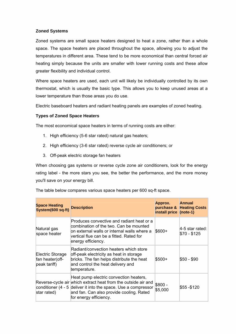
The table below compares various space heaters per 600 sq-ft space.
Space Heating System(600 sq-ft) Description
Approx. purchase & install price
Annual Heating Costs (note-1)
Natural gas space heater
Produces convective and radiant heat or a combination of the two. Can be mounted on external walls or internal walls where a vertical flue can be a fitted. Rated for energy efficiency.
$600+ 4-5 star rated: $70 - $125
Electric Storage fan heater(off-peak tariff)
Radiant/convection heaters which store off-peak electricity as heat in storage bricks. The fan helps distribute the heat and control the heat delivery and temperature.
$500+ $50 - $90
Reverse-cycle air conditioner (4 - 5 star rated)
Heat pump electric convection heaters, which extract heat from the outside air and deliver it into the space. Use a compressor and fan. Can also provide cooling. Rated for energy efficiency.
$800 - $5,000 $55 -$120

Electric space heater (continuous tariff)
Convection or radiant heaters which use 'general rate' electricity. Can be expensive to run, so should be limited to heating for short periods only (e.g. bedrooms)
$20+ $160 - $200
LPG space heater
Run on LPG. Produce convective and radiant heat or a combination of the two. $600+ $100 - $300
Slow combustion wood heater
Convection or radiant heaters burning wood. Efficiency and performance depends on quality of wood and method of operation.
$800+ $85 - $110
Note 1: Heater use for the winter quarter (90 days), for 8 hours per day, in an average
temperature of 8 to - 18°C
Central or Zoned System
The type that's best for you depends on the size of your facility, as well as the lifestyle. A
central heating system heats all spaces served to the level required by those in use and
is preferred for large facilities. In these cases, redundancy and backup capability is
generally considered in the design. The overall efficiency of a central system at peak
loading is generally high compared to multiple zone space heaters.
Zoned heating is a plus, if majority of areas remain unoccupied and if the people
preferences require different temperatures or they disagree about the most comfortable
temperature. Smaller commercial buildings typically use packaged split or roof top
equipment sized with this capability in mind. Redundancy is not factored into the design.
If a unit fails, the presumption is that it will be repaired or replaced in short order. Most
zone space heating systems permit room by room control and during off-load periods;
they afford significant energy and cost savings, particularly when spaces are used only
on occasional basis. Time controls, personnel detection controls and other devices are
normally integral to the unit.
As a general guideline, refer to the table below for a residential space:
If you need to heat…. Then…..
Only living zones Use one or more high efficiency space heaters
Living areas for long periods, sleeping areas for short periods
Use high efficiency space heaters for living zones and electric 'spot' heaters for sleeping areas, or a zoned central heating system
Living and sleeping areas for long periods but at different times of the day
Use a zoned central heating system
Living and sleeping areas both for long periods at the same time
Use a zoned central heating system
Bathrooms/ensuites Use radiant heaters, e.g. strip heaters, infra-red lamps
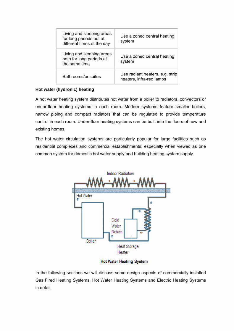
Hot water (hydronic) heating
A hot water heating system distributes hot water from a boiler to radiators, convectors or
under-floor heating systems in each room. Modern systems feature smaller boilers,
narrow piping and compact radiators that can be regulated to provide temperature
control in each room. Under-floor heating systems can be built into the floors of new and
existing homes.
The hot water circulation systems are particularly popular for large facilities such as
residential complexes and commercial establishments, especially when viewed as one
common system for domestic hot water supply and building heating system supply.
In the following sections we will discuss some design aspects of commercially installed
Gas Fired Heating Systems, Hot Water Heating Systems and Electric Heating Systems
in detail.

SECTION - 4 GAS & OIL FIRED SPACE HEATING SYSTEMS
Gas fired heating systems normally offer the most cost effective way to heat large
buildings. Gas or oil furnaces work on the same basic principle - the fuel is burned inside
an enclosed metal container, generally referred to as a fire box, and the exhaust gases
are vented to the exterior of the building. The combustion of the fuel warms the heat
exchanger, which radiates the heat into the air in the living area. This heated air is
circulated by gravity or pumped through the living area with a fan. Electric and oil fired
heaters are sometimes useful for very specific space heating applications when gas is
not available.
In this section, we will examine:
1. Codes & Standards
2. Classification of furnaces
3. Application considerations – forced air furnaces, unit heaters and radiant heaters
4. Combustion requirements and the factors affecting combustion efficiency
5. Combustion – air intake configurations
6. Venting – gravity vs. power venting
7. Gas heating furnace controls
8. Installations – Do’s and Don’ts
9. Safety precautions
10. Installation, Operation and Maintenance guidelines
Codes & Standards
In US, installation of gas furnaces must conform to local building codes. In the absence
of local codes, units must be installed according to the current National Fuel Gas Code
(ANSI-Z223.1/NFPA 54). In Canada, installation must conform to current National
Standard of Canada CSA-B149 Natural Gas and Propane Installation Codes, local
plumbing or waste water codes and other applicable local codes. (Refer to annexure 1
for details).
Classification of Furnaces
The furnaces are classified by the way they transfer heat to the space. There are three
ways in which gas fired heaters transfer their heat: direct fired heaters, indirect fired
heaters and radiant heaters.
Direct-fired Heating Systems
Direct-fired air heating systems push air past an open flame and the products of
combustion are delivered inside the building. There is no separation between the air to
be heated and the combustion chamber and the space air is heated directly.
Because the heated air contains the combustion gases, this style of heater can only be
used in well ventilated space and/or where large volumes of fresh outside air are
admitted to the heated space as a normal part of the building’s function. These have
application in many places, such as such as paint booths, distribution centers,
warehouses etc.
The efficiency of direct-fired systems tends to be higher than that for indirect fired
systems because there are no duct loses and generally do not have casing losses. They
also minimize flue losses because they are not vented to the outdoors. However,
efficiency is limited to about 90% because buildings heated in this manner must be
ventilated at the rate of 3.5 to 4.5 CFM for each 1000 BTUH input.
There are two types of direct fired air heating systems.
1. Blow-thru Heaters are essentially high temperature rise heaters, where the
burner is located downstream of the blower. These heaters allow for the very high
temperature rise to the tune of 160°F and therefore achieve the highest
BTU/CFM ratio, which means lower horsepower motors, less outside air and
reduced energy costs. These are well suited for large facilities such as
warehouse or industrial facilities.
2. Draw-thru heaters are essentially low temperature rise heaters which use a
draw-thru blower downstream from the burner. They move a large volume of
warm air through a low temperature rise and provide constant air output.
Generally these heaters are used as makeup air heaters for the facilities, which
exhaust large volumes of air during the heating season.
As a rule of thumb, high temperature rise blow-thru designs are best suited for space
heating, while low temperature rise draw-thru designs are best suited for heating makeup
air.
Codes and Standards
It is important to perform a detailed codes and standards search when considering a
design utilizing direct gas-fired heaters. There are two primary equipment standards and
two primary codes that provide specific operating and application guidelines for direct
gas-fired heaters:

1. ANSI Standard Z83.4, Non-Recirculating Direct Gas-Fired Industrial Air Heaters
for 100-percent outside-air application includes limitations on combustion
byproducts (CO less than 5.0 ppm, NO2 less than 0.5 ppm, and CO2 less than
4,000 ppm), gas-ignition control, combustion-air control, and flame safety.
2. ANSI Standard Z83.18, Recirculating Direct Gas-Fired Industrial Air Heaters for
recirculating direct gas-fired heaters includes limitations on combustion
byproducts (CO less than 25 ppm, NO2 less than 3 ppm, and CO2 less than 5,000
ppm), gas-ignition control, combustion-air control, and flame safety. The standard
prescribes a limit on air-temperature rise based on the percentage of recirculated
air.
3. International Fuel Gas Code. The International Fuel Gas Code has separate
sections to address non-recirculating direct-fired AHUs (Section 611) and
recirculating direct-fired AHUs (Section 612). Both sections note that direct-fired
heaters cannot supply any area with sleeping quarters, makeup air must come
from outside, motorized outside-air dampers/louvers must be proven open prior
to burner activation, systems must be controlled properly to prevent building over-
pressurization, and burner controls need to have a burner purge cycle.
4. NFPA Standard 54, National Fuel Gas Code. NFPA Standard 54 has similar
requirements as sections 611 and 612 of the International Fuel Gas Code. Its
requirements differ depending on whether a direct-fired heater is listed (Edison,
UL) or unlisted. Unlisted direct-fired AHU discharge-air temperature is limited to
150˚F.
Note that the codes are the mandatory requirements while standard are voluntary.
Indirect-fired Heating System
An indirect fired space heater is a very different machine than direct fired system. An
indirect gas-fired heater has a sealed combustion chamber in which all products of
combustion are discharged through a flue to the outside environment and no products of
combustion are discharged within the makeup air supplied to the building. This
arrangement is called indirect because there is no direct contact between the flame and
the heated inside room air.
These styles of heaters are frequently utilized for recirculating air applications and are
very effective in spaces which need to be heated quickly and which contain a strong
presence of people. Most heating systems in occupied areas are indirect fired and the
two systems are shown in the schematic below:

Indirect-fired duct-furnace system efficiencies are lower due to duct heat losses (heat
lost from warm-air ducts to the unheated spaces through which the ducts may be
directed), casing losses (heat lost from the heater to the space surrounding the heater),
flue loss (heat lost through walls and ceilings due to movement of heated air).
Indirect fired heaters are available in two configurations: 1) Up-flow arrangement and 2)
Down-flow arrangement.
When a furnace is installed in a basement it is considered an "Up flow" furnace, meaning
the cooler air is drawn at the base of the furnace, and the warm air exits out the top of
the furnace.
If a furnace is installed on the main floor of a space and the heat comes from floor
registers, it is a "Down flow" furnace. In a down flow furnace, the cool air enters the
furnace at the top and the warmed air exits at the bottom.
Radiant Fired Heaters
In a radiant gas-fired heater, the flame is used to heat a surface which in turn emits heat
in the form of rays. The materials used in this process can withstand extremely high
temperatures. Radiant heaters have very good system efficiencies for the following
reasons:
1. Radiant heaters do not heat the air; they heat the objects in the space by
radiation. Occupants can be comfortable at a lower air temperature; where a
lower air temperature means lower losses through the building’s walls;

2. Radiant heaters require no forced air circulation, minimizing convection losses
through the building’s walls;
3. Radiant heaters normally are unvented but buildings must be ventilated at the
rate of 3.5 to 4.5 CFM for each 1000 BTUH input. Such ventilation is usually
accomplished with powered exhausters installed at the highest point of the roof.
Radiant gas-fired heaters are fast and efficient and can be used conveniently in industrial
processes like the drying of paper, paint, and textiles as well as space heating.
Application and Equipment Considerations
In addition to being categorized by their method of heat transfer (indirect-fired, direct-
fired and radiant), heaters are categorized according to their construction features.
Forced-air heaters fall into two broad category: 1) Duct furnaces and 2) Unit heaters.
Forced Air Ducted Furnaces
1. Conventional natural gas-fired furnaces - This system consists of a furnace
with a naturally aspirating gas burner, which means that air for combustion is
drawn in from the surrounding area by the natural forces of hot air rising. The
combustion gases pass through the furnace where they give up heat across a
heat exchanger and are exhausted to the outside through a flue pipe and vent. A
dilution device, known as draft hood serves to isolate the burner from outside
pressure fluctuations at the vent exit by pulling varying quantities of heated space
air into the exhaust as required. A circulating fan passes cooled space air from
the return ducts over the furnace heat exchanger, where the air is warmed up
and passed into the ductwork for distribution around the indoor space.
Note that there are two entirely separate air movement paths: first, the
combustion path supplies air to the burner and to the draft hood and carries hot
combustion gases through the burner, heat exchanger and flue pipe to the vent
outdoors and second, the heat distribution and cold air return path circulates and
heats the air indoors.
These systems usually have seasonal efficiencies of about 60%. A minor
improvement in efficiency comes with adding a vent damper in the flue exhaust.
By closing off the vent during the off cycle, the damper prevents some of the
warm air from being drawn up the flue and lost to the outdoors.
These furnaces usually have an electric or electronic ignition. Older units were
equipped with a standing (continuously lit) pilot light; the newer ones feature
electric ignition. Fuel savings are generally in the 3-9% range, relative to a
conventional furnace.
2. Conventional oil furnaces – This is similar to a natural gas furnace, but the
dilution device is a barometric damper; a plate that acts as a valve on the side of
the flue pipe. The damper isolates the burner from changes in pressure at the
chimney exit by pulling varying quantities of heated room air into the exhaust.
The quantity of air drawn through the barometric damper is much greater than the
quantity required for combustion and can represent 10% to 15% of the total heat
loss. The burner is a high-pressure gun type, with a blower fan to help mix the oil
and air for good combustion. A conventional oil furnace with a cast-iron head
burner has a seasonal efficiency about 60%. Replacing the conventional burner
with a flame retention head burner will save 10-15% on the fuel bill.
3. Mid-efficiency gas furnaces - Mid-efficiency gas furnaces mainly use a naturally
aspirating burner and do not have a continuously lit pilot light. They are equipped
with a powered exhaust, usually with a built-in induced draft fan, and they do not
have a draft hood. With more heat exchange, no dilution air, and high resistance
to flow during the off cycle, seasonal efficiency is much higher for mid-efficiency
gas furnaces than for conventional furnaces, offering energy savings of 15 to 25
percent over conventional gas furnaces. These systems can be vented through a
properly sized chimney or out the side wall of the house using high-grade
stainless steel.
One word of caution: do not buy a mid-efficiency furnace that is more than 82%
efficient. These systems often have condensation problems in the furnace or
venting system. There is also some concern about the longevity of the high

temperature plastic pipe used to vent many of these mid-efficiency units. For
higher efficiency, get a condensing furnace.
4. Mid-efficiency oil furnaces use a more efficient high-static retention burner.
This type of furnace also features an improved low-mass combustion chamber
(usually ceramic fiber) and passes the hot combustion gases through a superior
heat exchanger that enables the circulating space air to extract more heat. The
barometric damper, with its large requirement for air to dilute the combustion
gases, has been eliminated in the most efficient of these designs. Benefits of a
good mid-efficiency furnace are much lower combustion and dilution air
requirements as well as more power to exhaust the combustion products (both
advantages in new, tighter housing); a safety shutoff in case of draft problems;
and a more effective venting system. Mid-efficiency oil furnaces can have
seasonal efficiencies of 85-89% and use 25-30% less fuel than a conventional oil
furnace producing the same amount of heat.
5. High Efficiency Condensing Gas Furnaces – These are the most efficient
furnaces available, with seasonal efficiencies between 89 and 97 percent. Most
have burners similar to conventional furnaces, with draft supplied by an induced
draft fan. There are additional (or enlarged) heat exchange surfaces made of
corrosion-resistant materials (usually stainless steel) that extract most of the heat
remaining in the combustion byproducts before they are exhausted. Because of
increased heat transfer, the exhaust gases temperature drops to the dew point of
the water vapor, causing the vapor to condense and give up 970 BTU for every
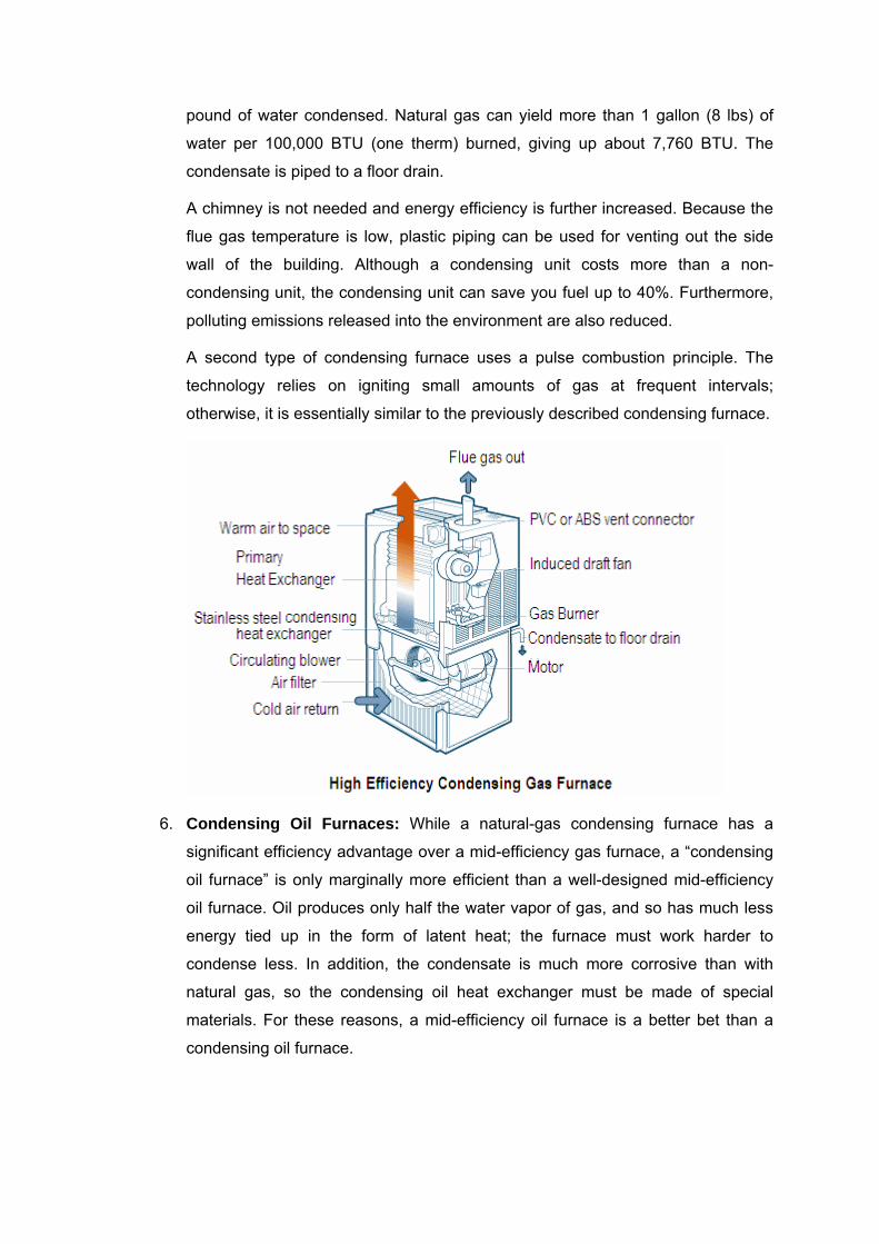
pound of water condensed. Natural gas can yield more than 1 gallon (8 lbs) of
water per 100,000 BTU (one therm) burned, giving up about 7,760 BTU. The
condensate is piped to a floor drain.
A chimney is not needed and energy efficiency is further increased. Because the
flue gas temperature is low, plastic piping can be used for venting out the side
wall of the building. Although a condensing unit costs more than a non-
condensing unit, the condensing unit can save you fuel up to 40%. Furthermore,
polluting emissions released into the environment are also reduced.
A second type of condensing furnace uses a pulse combustion principle. The
technology relies on igniting small amounts of gas at frequent intervals;
otherwise, it is essentially similar to the previously described condensing furnace.
6. Condensing Oil Furnaces: While a natural-gas condensing furnace has a
significant efficiency advantage over a mid-efficiency gas furnace, a “condensing
oil furnace” is only marginally more efficient than a well-designed mid-efficiency
oil furnace. Oil produces only half the water vapor of gas, and so has much less
energy tied up in the form of latent heat; the furnace must work harder to
condense less. In addition, the condensate is much more corrosive than with
natural gas, so the condensing oil heat exchanger must be made of special
materials. For these reasons, a mid-efficiency oil furnace is a better bet than a
condensing oil furnace.

UNIT HEATERS
Unit heaters are compact, completely self-contained, normally non-duct indirect-fired
systems, which eliminate duct and casing losses and therefore, their system efficiency is
somewhat higher. Some unit heaters can also be suitable for ducted air circulation.
Unit heaters are excellent for areas where a concentrated heat source is desired and are
generally mounted near the ceiling. Multiple heaters can be placed in larger space,
allowing you to adjust the temperatures in different areas. These are often installed
around the perimeter of a building.
Advantages include:
• Tend to be more economical than central forced air heating simply because the
units are smaller with lower running costs;
• Allow for greater flexibility and individual control;
• Redundancy in case one unit fails and intermittent fan operation that reduces
electrical costs;
• Can be installed near the ceiling to get more floor space but due to limited air
throw, their efficiency decreases with increasing height above the floor.
Unit heaters are available with either fan-powered or blower-powered recirculated air
movers. Fans deliver air at large flow rates against low resistance. Blowers are used in
high static systems to distribute air through ductwork where resistance is high and lower
volumes are required or to “throw” heated air a considerable distance in a ductless
system. Most unit heaters employ a propeller fan, which is cycled on and off in a
sequence related to the on-and-off cycling of the burner.
A wide range of facilities, such as factories, garages, storerooms, supermarkets,
gymnasiums, swimming-pool enclosures and auto showrooms, can be heated for
occupant comfort with unit heaters.
Measure of Efficiency for Furnaces
The efficiency of a gas furnace is measured by the Annual Fuel Utilization Efficiency
(AFUE), a rating that takes into consideration losses from pilot lights, start-up and
stopping. The minimum AFUE for most furnaces is now 78%, with efficiencies ranging up
to 97% for furnaces with condensing heat exchangers. The AFUE does not consider the
unit’s electricity use for fans and blowers, which can easily exceed $50 annually. An
AFUE rating of 78% means that for every $1.00 worth of fuel used by the unit,
approximately $.78 worth of usable heat is produced. The remaining $.22 worth of
energy is lost as waste heat and exhausted up the flue. Efficiency is highest, if the
furnace operates for longer periods. Oversized units run intermittently and have reduced
operating efficiencies.
Furnaces with AFUEs of 78% to 87% include components such as electronic ignitions,
efficient heat exchangers, better intake air controls, and induced draft blowers to exhaust
combustion products.
Furnaces are often classified as standard, mid and high efficient units. A standard
furnace is one whose efficiency is below 70%, a mid efficient furnace is one whose
efficiency is between 71% and 82%, and a high efficient condensing furnace is one with
efficiency above 90%.
Combustion Efficiency
In order to understand the basics of combustion efficiency, the combustion process must
be understood. Stable combustion conditions require three inputs: fuel, oxygen and a
source of ignition. If the combustibles themselves can provide this third element as they
burn, the source of ignition can be turned off. The products of complete combustion are
heat energy, carbon dioxide, water vapor, nitrogen and other gases (excluding oxygen).

Complete combustion takes place when there are enough oxygen atoms to match up
with all the carbon and hydrogen atoms present. Three important facts need to be
remembered for ensuring complete combustion:
1. Burning fuel gas completely produces only harmless carbon dioxide, water vapor;
nitrogen and other gases (excluding oxygen);
2. A definite amount of fuel requires a definite amount of oxygen for complete
combustion; and
3. Definite amounts of combustion products are formed in burning a fuel gas
completely.
When an insufficient amount of air is supplied to the burners, the result is dangerous and
costly incomplete combustion. Incomplete combustion will result in formation of carbon
monoxide; a poisonous gas that can cause death when breathed. Carbon monoxide can
be particularly dangerous because it has no odor, color or taste and has increasingly
serious effects at increasing concentrations and exposure times. Incomplete combustion
is also costly because not all the heat available in the fuel is released when carbon
monoxide is formed, so there is a waste of fuel resulting in inefficiency and the potential
for an explosion.
To avoid these costly and unsafe conditions, furnaces are normally operated at an
“excess air”; the amount of air over and above the theoretical requirement. This excess
air level also provides operating protection from an insufficient oxygen condition caused
by variations in fuel composition and "operating slop" in the fuel-air control system.
Typical optimum values of excess air levels (and equivalent percentage of oxygen by
volume) are shown in the table below:
Typical Optimum Excess Air Levels
Fuel Type Firing Method
Optimum Excess Air
Equivalent Percent O2
(by Volume)
Natural Gas - 5%- 10% 1% - 2%
Propane - 5%- 10% 1% - 2%
Coke Oven Gas - 5%- 10% 1% - 2%

No #2 Oil Steam
atomized
10%- 15% 2% - 3%
No #6 Oil Steam
atomized
10%- 15% 2% - 3.5%
It is important to understand that "excess air" and "excess oxygen" is not the same.
Because air is roughly 21% oxygen by volume, 50% excess air is approximately equal to
10.5% oxygen remaining in the exhaust stack.
While insufficient air to the burners can be dangerous, airflows in excess of those
needed for stable flame propagation needlessly increase flue gas heat losses and
consequently lower efficiency. Minimizing these losses requires monitoring for two
variables: the percentage of O2 (or CO2), and the stack temperature. Very high percent
of O2 in the flue stack means lower efficiency. The percentage of O2 (or CO2) can be
measured by using simple devices containing gas-absorbing analyzers.
These figures show the relationship between proper tune-up, proper heat transfer and
efficiency.
As fuel is such a dominant cost factor, the boiler efficiency needs to be kept high to keep
operating costs low. Decreases in efficiency over time can indicate the need for minor
adjustments or repairs. In some cases, only control linkages, a fuel valve, or an air
damper may need to be adjusted. In other cases, a worn burner tip or control cam may
need replacing. High stack temperatures may also indicate the need for cleaning. In any
situation, decreases in efficiency indicate the need for professional maintenance.
Controlled and Explosive Combustion
Since complete combustion is necessary for both safety and economy in space heating,
it is important to supply air and fuel gas to heating devices in the proper amounts and at
proper rates to ensure complete burning of the gas in a steady controlled flame.
Explosive combustion can result when an air-gas mixture does not ignite the instant it
leaves the burner. The air-gas mixture may then collect in the combustion chamber and
burn almost instantaneously (explode). The gas burners of heaters and furnaces are
designed and equipped for safe and economical controlled combustion, when they are
correctly adjusted and operated.
Combustion and Vent Techniques
Most furnaces use the surrounding air for combustion and others bring combustion air
directly into the combustion chamber through sealed plastic piping that extends to
outside air. Typical commercial terminology on the way furnaces take combustion air and
exhaust flue gases are:
1. Direct Vent or Sealed installations - Combustion air is taken from outdoors and
flue gases are discharged outdoors. Direct vent furnaces can be installed within
the conditioned area of a living space since they do not rely on inside air for safe
operation.
2. Non-Direct Vent installations - Combustion air is taken from indoors and flue
gases are discharged outdoors. Non-direct vent furnaces must receive adequate
outside air for combustion and exhaust venting. The primary concern with non-
direct vent units is that a malfunctioning heater may allow flue gases inside.
3. Un-vented installations - Combustion air is taken from indoors and the flue
products are discharged into the space. In unvented installations, the products of
combustion: carbon dioxide (CO2), water (H2O), and carbon monoxide (CO) are
discharged into the space. These heaters should be used only in areas where
adequate ventilation is available. All unvented gas-fired space heaters should be
equipped with an oxygen depletion sensor (ODS). An ODS detects a reduced
level of oxygen in the area where the heater is operating and shuts off the heater
before a hazardous level of carbon monoxide accumulates. These heaters also
have labels that warn users about the hazards of carbon monoxide. Always have

your gas heater and venting system professionally installed and inspected
according to local codes.
Ventilation Air Configurations
Unless outside air is brought into the space for combustion, negative pressure will build
to the point that a downdraft can occur in the furnace vent pipe or chimney. As a result,
combustion gases enter the living space creating a potentially dangerous situation. The
requirements for providing air for combustion and ventilation depend largely on whether
the furnace is installed in an unconfined or a confined space.
Confined Spaces:
A confined space is a space having volume less than 50 cubic feet per 1,000 BTUH of
the combined input rating of all appliances installed in that space. This definition includes
furnace closets or small equipment rooms. The confined space must have two
permanent openings to permit outside air. Two air intake configurations are as follows:
1) Air from Inside: If the confined space that houses the furnace adjoins a space
categorized as unconfined, the air can be brought in by providing two permanent
openings between the two spaces. Each opening must have a minimum free area of
1 square inch per 1,000 BTUH of total input rating of all gas-fired equipment but not
less than 100 square inches for each opening. One opening shall be within 12 inches
of the top of the enclosure and the other within 12 inches of the bottom.
2) Air from Outside: If air from outside is brought in for combustion and ventilation, the
confined space shall be provided with two permanent openings. One opening shall
be within 12 inches of the top of the enclosure and one within 12 inches of the
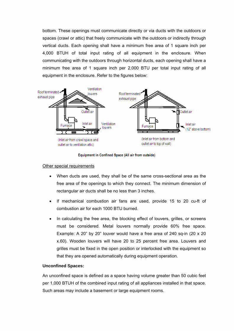
bottom. These openings must communicate directly or via ducts with the outdoors or
spaces (crawl or attic) that freely communicate with the outdoors or indirectly through
vertical ducts. Each opening shall have a minimum free area of 1 square inch per
4,000 BTUH of total input rating of all equipment in the enclosure. When
communicating with the outdoors through horizontal ducts, each opening shall have a
minimum free area of 1 square inch per 2,000 BTU per total input rating of all
equipment in the enclosure. Refer to the figures below:
Other special requirements
• When ducts are used, they shall be of the same cross-sectional area as the
free area of the openings to which they connect. The minimum dimension of
rectangular air ducts shall be no less than 3 inches.
• If mechanical combustion air fans are used, provide 15 to 20 cu-ft of
combustion air for each 1000 BTU burned.
• In calculating the free area, the blocking effect of louvers, grilles, or screens
must be considered. Metal louvers normally provide 60% free space.
Example: A 20” by 20” louver would have a free area of 240 sq-in (20 x 20
x.60). Wooden louvers will have 20 to 25 percent free area. Louvers and
grilles must be fixed in the open position or interlocked with the equipment so
that they are opened automatically during equipment operation.
Unconfined Spaces:
An unconfined space is defined as a space having volume greater than 50 cubic feet
per 1,000 BTUH of the combined input rating of all appliances installed in that space.
Such areas may include a basement or large equipment rooms.
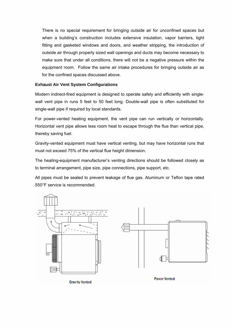
There is no special requirement for bringing outside air for unconfined spaces but
when a building’s construction includes extensive insulation, vapor barriers, tight
fitting and gasketed windows and doors, and weather stripping, the introduction of
outside air through properly sized wall openings and ducts may become necessary to
make sure that under all conditions, there will not be a negative pressure within the
equipment room. Follow the same air intake procedures for bringing outside air as
for the confined spaces discussed above.
Exhaust Air Vent System Configurations
Modern indirect-fired equipment is designed to operate safely and efficiently with single-
wall vent pipe in runs 5 feet to 50 feet long. Double-wall pipe is often substituted for
single-wall pipe if required by local standards.
For power-vented heating equipment, the vent pipe can run vertically or horizontally.
Horizontal vent pipe allows less room heat to escape through the flue than vertical pipe,
thereby saving fuel.
Gravity-vented equipment must have vertical venting, but may have horizontal runs that
must not exceed 75% of the vertical flue height dimension.
The heating-equipment manufacturer’s venting directions should be followed closely as
to terminal arrangement, pipe size, pipe connections, pipe support, etc.
All pipes must be sealed to prevent leakage of flue gas. Aluminum or Teflon tape rated
550°F service is recommended.

Rules for Gravity Vents
There are several rules to follow to assure proper venting of gravity vented equipment:
1. Keep vent runs as straight as possible with few turns or bends.
2. Never use a vent size smaller than the size recommended by the equipment
manufacturer.
3. All vents must terminate with a proper wind proof vent cap.
4. Limit horizontal vent runs to a maximum of 75% of the vertical run. Example, if
the vertical run is 10 ft, the horizontal run must not exceed 7.5 ft.
5. Horizontal runs must be pitched with a minimum upward slope of .25 inch per foot
of run.
6. Vents must terminate a minimum of 2.5 ft above any obstructions within a 10 ft
radius of the vent pipe.
7. Always provide a drip leg as near to the equipment as possible. This to prevent
condensation of flue gases in the vent pipe from entering the equipment.
8. Keep combustible material 6 inches away from single wall vent pipe
9. When venting into a common vent, the area of the common vent should be equal
to or greater than the area of the largest vent plus 50% of the area of all
additional vents.
10. When venting into a common vent, the individual vents should enter at different
levels.
Rules for Power Vents
The rules for power vented equipment generally are the same as gravity vented
equipment with the following exceptions:
1. Approved power exhausted equipment may have its vent system terminate
horizontally out of a wall. A proper vent cap must still be installed.
2. Horizontal run lengths may exceed vertical run lengths. The combined total run
length must not exceed the manufacturer’s recommendations.
3. If elbows are used in the vent system, you must attribute 6 ft. of equivalent length
of run for each 90 degree elbow.
4. If a vent terminates horizontally out of a wall, make sure it does not terminate
near an air inlet opening. A minimum of 3 ft. is recommended.

5. Make sure the horizontal vents are sufficiently high enough, or guarded so as to
prevent accidental contact by people or equipment.
6. No common venting should be utilized.
Gas Heating Furnace Controls
Duct furnaces may be equipped with any of several gas-control systems:
1. Single-stage control: A single stage control is simply on or off, i.e. the gas valve
provides full fire on a call for heat.
2. Two-stage control for heating applications: A two-stage control was
developed with comfort in mind. Here is how it functions: When the thermostat
activates the furnace, it comes on at 2/3rd the strength (burning gas at 65% of
maximum). If, after 10 minutes of operation, the thermostat is still calling for heat,
the furnace will switch to 100%. What that accomplishes is a uniform heating of
the entire space. If a furnace kicks on at full power and dumps hot air into the
space to satisfy the thermostat, it will shut off leaving cool air still circulating the
space, i.e. the furnace will have to kick in again. Two-stage furnaces are more
efficient and more effective at heating the space. Furnaces are like light bulbs;
they operate better if they are turned on and left on. If you flick a light switch on
and off, and over and over, that bulb is toast. The same goes for furnaces.
Running at 65% for 9 minutes is better than 100% for 3 minutes several times an
hour. A two-stage furnace uses less gas and is easier on the machine.
3. Two-Stage Variable: Two-stage variable control was developed with the
knowledge that subtle circulation of heated air is the most effective way to heat a
space. The furnace part is the same as a two-stage; the difference is in the
blower motor. In a single-stage, if you want your fan on for circulation, that fan is
on high. It is the only option it has. Not only is that hard on the utility bill, but a fan
on high means the warm air is moving fast as a cool breeze. In a variable mode,
the fan turns over slowly to maintain air circulation while being easy on the utility
bill. By the way, most air cleaners and filtration devices are only active when the
furnace blower is on. So the best way to utilize these accessories is to have a
variable speed blower. By switching its blower fan from AC current to DC current,
it only draws 1/10th the electricity.
4. Electronically Modulated Control – Uses solid-state circuitry that smoothly
varies the gas input between 50% and 100% of the unit’s rated capacity, as
required by a call for heat from a wall-mounted room sensor. Such systems may
or may not be certified for use with propane gas.
NOTE: Electronic modulation is available for both direct-fired and indirect fired
equipment. Check the manufacturer’s specifications for availability with certain
gaseous fuels.
5. Mechanically Modulated Control – Uses a nonelectric, capillary-actuated
system which smoothly varies the gas manifold pressure between 50% and
100% firing as required on a call from a thermostatic sensor. This system cannot
be used on power-vented equipment unless the air mover is operated
continuously.
Unit Heater Controls
In unit heater applications, individual room thermostats for ON-OFF operation provide an
adequate and simple means of control. Unit heaters are available with summer/winter
switches to permit fan operation without burner operation during warm weather when
only air circulation is desired.
Pilot-ignition control systems - Unit heaters contain one of the following types of
ignition systems:
• Manual match-lit gas pilot with 100% shut off;
• Spark-ignited intermittent gas pilot;
• Spark-ignited gas pilot with timed lockout;
• Direct spark whereby an electrical spark ignites the main burner;
• Hot surface ignited gas pilot; and
• Hot surface ignited main burner.
Gas-control Systems - Unit heater gas-control systems may contain a single-stage gas
valve (which provides full fire on a call for heat) or a two-stage valve (which fires at either
100% or approximately 50% as required by a remote two-stage thermostat).
Installation – Do’s and Don’ts
1. The furnace may be installed in alcoves, closets, attics, basements, garages, and
utility rooms in the up-flow position. When a furnace is installed in an attic, the
passageway to and service area surrounding the equipment shall be floored.
2. When the furnaces are installed in an attic or other insulated space, keep
insulation away from the furnace.

3. For installation in a residential garage, the furnace must be installed so that the
burner(s) and the ignition source are located no less than 18 inches above the
floor. The furnace must be located or protected to avoid physical damage by
vehicles.
4. The furnace shall not be installed directly on carpeting, tile, or other combustible
material other than wood flooring.
5. Place the furnace as close to the center of the air distribution system as possible.
The furnace should also be located close to the chimney or vent termination
point.
6. When the furnace is installed in non-direct vent applications, do not block the
furnace combustion air opening with clothing, boxes, doors, etc. Air is needed for
proper combustion and safe unit operation.
7. When the furnace is installed in an unconditioned space, consider provisions
required to prevent freezing of condensate drain system.
8. When this furnace is used with cooling units, it shall be installed in parallel with,
or on the upstream side of cooling units to avoid condensation in the heating
compartment.
9. The furnace must be installed so that its electrical components are protected from
water. The furnace must be electrically grounded according to the current
National Electric Code, ANSI/NFPA No. 70.
Always refer to local codes and guidelines of authorities having jurisdiction before
installation.
SAFETY PRECAUTIONS
1. Gas-fired appliances are not designed for use in hazardous atmospheres
containing flammable vapors, combustible dust or chlorinated or halogenated
hydrocarbons.
2. All components of a gas supply system must be leak tested prior to placing
equipment in service.
3. For best operation, gravity vented outdoor heaters should be located on the roof
or slab with at least a 20-foot radius between the center of the vent cap and the
obstructions such as walls, parapets or cupolas.
4. Failure to provide proper venting could result in death, serious injury, and/or
property damage. The unit must be installed with a flue connection and proper
vent to the outside of the building. Follow installation codes and venting
recommendations in the installation manual for this heater. Safe operation of any
gravity-vented gas equipment requires a properly operating vent system, correct
provision for combustion air and regular maintenance and inspection.
5. The use and storage of gasoline or other flammable vapors and liquids in open
containers in the vicinity of this appliance is hazardous.
6. Joints where flue ducts attach to the furnace must be sealed securely to prevent
air leakage into the draft hood or burner rack area. Leakage can cause poor
combustion, pilot problems, shortened heat exchanger life, and can cause poor
performance.
7. Make sure the thermostat has an adequate volt-ampere rating for the total load to
be placed on it. Add up the amperage ratings of all relay coils, valve-solenoid
coils or valve hot-wire coils, etc., and match the thermostat rating to the total.
8. The appliance is equipped for a maximum gas supply pressure of 1/2 pound, 8
ounces or 14 inches water column. NOTE: supply pressure higher than 1/2
pound require installation of an additional service regulator external to the unit.
9. The appliance must be isolated from the gas supply piping system by closing its
individual shutoff valve during any pressure testing of the gas supply piping
system at a test pressure equal to or more than 1/2 PSIG (3.45 KPa).
10. Due to the high voltage on the pilot spark wire and pilot electrode, do not touch
when energized.
11. The operating valve is the prime safety shutoff. All gas supply lines must be free
of dirt or scale before connecting the unit to ensure positive closure.
Operation and Maintenance Guidelines
During the later part of the summer it is time to start up the heating system. This is the
time to make some routine checks which are necessary to ensure that your heating
equipment will be ready to function properly in the fall and winter.
1. Check equipment for physical damage. Check the sheet metal, fans and air
movers, wiring, fuel piping and vent system.
2. Check for the cleanliness of the equipment’s heat exchanger and burner.
3. Check the vent system; sometimes birds will make nests in the vent system.
4. Check to make sure no obstructions block the air intake or air discharge of the
equipment.

5. Check lubrication of the motors on fans and pumps. With the power off check to
see that the motor shafts turns freely.
6. Check the belt tension on the equipment that utilizes a centrifugal blower system.
7. Check the heat exchanger of the equipment for any signs of cracks or corrosion.
A flash light can be useful to check the inside and outside of the heat exchanger.
8. Check the heat exchanger of the equipment for signs of overheating. Metal that
has been overheated will have a dark discoloring of the overheated area.
Overheating could be the result of over-firing, improper venting, or inadequate
combustion air.
9. Inspect the burner for general cleanliness. It is not uncommon to find that spiders
or mice have nested in the control or burner area.
10. Check the control wiring to make sure the connections are tight.
11. Check to make sure the manual valves are opened.
12. If your space has an alarm system, make sure it is operational.
It is recommended that a record be kept of the date the heating equipment service was
performed. It is also recommended that these same service checks be performed on a
periodic basis throughout the heating season. By keeping a service record and updating
it, it is less likely that this important maintenance will be overlooked.
SECTION - 5 HOT WATER HEATING SYSTEMS
Hot water heating (sometimes called hydronic heating) systems use water or a water-
based solution as a medium to transport heat from a heat source to one or several heat
emitters. The hot water then radiates heat and warms the air within the space. As the
water circulates it begins to cool and is then circulated back to a boiler for reheating.
These systems are useful as centralized heating systems in large building complexes
and can be designed as forced air or radiant heating systems.
• In a forced air application the heated water is passed through a coil (much like an
automobile radiator) and a blower pushes (or pulls) the cool air across the coil. At
the coil, the air picks up the heat energy and the warm air is directed to the living
area.
• In radiant systems the heated water is run through pipes in the floor (or walls)
and the floor gets warm and the heat radiates into the living area.
In this section we will examine:
1. What is hydronic heating?
2. Why hydronic heating?
3. Gravity circulation vs. forced circulation
4. Heat transfer to space – terminal units
5. Hot water system design – primary elements:
• Sizing distribution system
• Estimating water flow rate
• Sizing supply piping
• Piping configuration – direct vs. reverse return system
• Sizing the circulator
6. Secondary components such as expansion tanks, safety devices, instrumentation
controls
7. Radiant floor heating system design
What is Hydronic heating?
Hydronic heating systems use hot water to move heat from where it is produced to
where it is needed. Heat is absorbed by the water at a heat source, conveyed by the
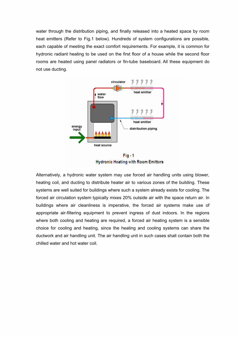
water through the distribution piping, and finally released into a heated space by room
heat emitters (Refer to Fig.1 below). Hundreds of system configurations are possible,
each capable of meeting the exact comfort requirements. For example, it is common for
hydronic radiant heating to be used on the first floor of a house while the second floor
rooms are heated using panel radiators or fin-tube baseboard. All these equipment do
not use ducting.
Alternatively, a hydronic water system may use forced air handling units using blower,
heating coil, and ducting to distribute heater air to various zones of the building. These
systems are well suited for buildings where such a system already exists for cooling. The
forced air circulation system typically mixes 20% outside air with the space return air. In
buildings where air cleanliness is imperative, the forced air systems make use of
appropriate air-filtering equipment to prevent ingress of dust indoors. In the regions
where both cooling and heating are required, a forced air heating system is a sensible
choice for cooling and heating, since the heating and cooling systems can share the
ductwork and air handling unit. The air handling unit in such cases shall contain both the
chilled water and hot water coil.
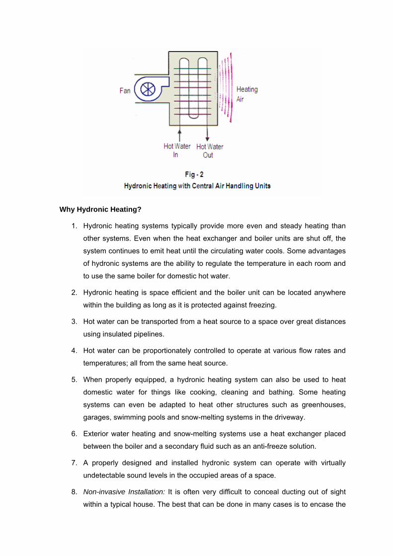
Why Hydronic Heating?
1. Hydronic heating systems typically provide more even and steady heating than
other systems. Even when the heat exchanger and boiler units are shut off, the
system continues to emit heat until the circulating water cools. Some advantages
of hydronic systems are the ability to regulate the temperature in each room and
to use the same boiler for domestic hot water.
2. Hydronic heating is space efficient and the boiler unit can be located anywhere
within the building as long as it is protected against freezing.
3. Hot water can be transported from a heat source to a space over great distances
using insulated pipelines.
4. Hot water can be proportionately controlled to operate at various flow rates and
temperatures; all from the same heat source.
5. When properly equipped, a hydronic heating system can also be used to heat
domestic water for things like cooking, cleaning and bathing. Some heating
systems can even be adapted to heat other structures such as greenhouses,
garages, swimming pools and snow-melting systems in the driveway.
6. Exterior water heating and snow-melting systems use a heat exchanger placed
between the boiler and a secondary fluid such as an anti-freeze solution.
7. A properly designed and installed hydronic system can operate with virtually
undetectable sound levels in the occupied areas of a space.
8. Non-invasive Installation: It is often very difficult to conceal ducting out of sight
within a typical house. The best that can be done in many cases is to encase the

ducting in exposed soffits. Such situations often lead to compromises in duct
sizing and/or placement. By comparison, hydronic heating systems are easily
integrated into the structure of most small buildings without compromising their
structure or the aesthetic character of the space. The underlying reason for this is
the high heat capacity of water. A given volume of water can absorb almost 3500
times more heat as the same volume of air for the same temperature change.
The volume of water that must be moved through a building to deliver a certain
amount of heat is only about 0.03 percent that of air. This greatly reduces the
size of the distribution “conduit”. Here’s an example of what that means: A ¾
inch diameter tube can carry the same amount of heat as a 14” x 8” duct.
Hydronic systems using small flexible tubing are much easier to retrofit into
existing buildings than is ducting. The tubing can be routed through closed
framing spaces much like electrical cable. Another benefit is that not only a ¾
inch diameter tube shall require considerably less material for insulation; the heat
loss of the 14” x 8” inch duct is almost ten times greater than that of the ¾ inch
tube when insulated with the same material. For buildings where utility space is
minimal, small wall-hung boilers can often be mounted in a closet. In many
cases, these compact boilers supply the building’s domestic hot water as well as
its heat. The entire system might occupy less than ten square feet of floor area.
Disadvantages
The installed cost of hydronic systems is higher than that of direct fired forced-air
systems, they can be slow to warm up, and there is no capability for central air
conditioning, air filtering, or ventilation.
Unless your hydronic heating system also has a fan installed, it cannot provide the
cooling, humidification, air filtration or forced air circulation that alternative heating
systems can. In addition, excessive heat gains from sources such as sunlight can’t be
easily transferred to other areas within the home.
Another factor to consider when installing a hydronic heating system is its vulnerability to
damaging impacts and leaks. The system will only function correctly if all piping is in full
working order. If the piping becomes damaged, water leaks can rot the flooring and
structure of the building.
Design Alternatives
Hot water heating system design can be either a gravity heating system or a forced
heating system.

1) Gravity Circulation: In a gravity heating system, the circulation of water is a result of
the difference in density between the hot water in the supply line and the cold water
in the return line. The hot water tends to flow upwards and cold water tends to flow
downwards. The elevation of the supply and return lines are therefore important for
proper functionality. Gravity systems have many disadvantages:
• The low differential pressure in the system demands increased pipes and valves
dimensions. They require very large diameter piping for supply and return mains.
• The gravity system will also have a relative low heating capacity because of low
medium temperatures in the heating elements. The low temperature water
provided a heat emission rate of only around 150 BTU’s per square foot of
radiation per hour. Consequently, radiators had to be large.
The gravity system is simple but limited to smaller systems.
2) Forced Circulation: In a forced circulation system, a circulating booster pump is
used to overcome the objections of the gravity system while retaining all the
advantages of heating with hot water. Water is circulated regardless of the
temperature forces between hot and cold water. Forced circulation systems allow
design using higher water temperatures resulting in higher emission rates. A radiator
of 60 square feet with an average water temperature of 170°F will emit heat at a rate
of 150 BTU’s per square foot per hour, or 9000 BTU’s per hour. A radiator of 45
square feet with 197°F water will emit 200 BTU’s per square foot per hour; producing
the same 9000 BTU’s per hour. It is not necessary to be careful with the piping
elevations. The pipes, valves and heating elements, radiators and air heaters can be
downsized because of higher flow and higher mean temperatures.
HYDRONIC HEATING TERMINAL UNITS
The design of hydronic heating systems is more complex than that of other heating
systems and can be more expensive to install. Operating costs can be higher than for
simpler systems unless good design, proper operation and maintenance of the system
and all of its components are carried out regularly. A variety of heat distribution methods
and equipment are available when choosing a hydronic heating system including:
RADIATORS:
Radiators are heat emitters (made up of elements, panels, tubes or blades) which give
out heat by natural convection and radiation. Radiators can be classified according to
type, i.e. cast iron, radiators, steel radiators and aluminum radiators.
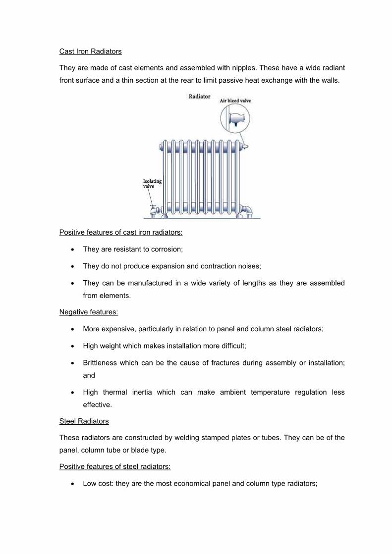
Cast Iron Radiators
They are made of cast elements and assembled with nipples. These have a wide radiant
front surface and a thin section at the rear to limit passive heat exchange with the walls.
Positive features of cast iron radiators:
• They are resistant to corrosion;
• They do not produce expansion and contraction noises;
• They can be manufactured in a wide variety of lengths as they are assembled
from elements.
Negative features:
• More expensive, particularly in relation to panel and column steel radiators;
• High weight which makes installation more difficult;
• Brittleness which can be the cause of fractures during assembly or installation;
and
• High thermal inertia which can make ambient temperature regulation less
effective.
Steel Radiators
These radiators are constructed by welding stamped plates or tubes. They can be of the
panel, column tube or blade type.
Positive features of steel radiators:
• Low cost: they are the most economical panel and column type radiators;

• Low weight: they weigh approximately 65 to 70% less than cast iron radiators
with the same heat output;
• They blend in easily with their surroundings: the wide range of range of types and
geometrical shapes available can easily be integrated into their environment; and
• Low thermal inertia on the panel types.
Negative features:
• High thermal inertia of the column and tube types (i.e. on high water content
types). This characteristic can make ambient temperature regulation less
effective;
• The welded panel, blade and column types not assembled from sections; and
• Possible corrosion: these radiators are easily affected by external corrosion
unless they have suitable surface coatings.
Aluminum Radiators
These radiators are assembled from components made by extrusion or pressure die
casting using nipples.
Positive features:
• Relatively low cost: they cost considerably less than cast iron radiators;
• Lightweight construction: they weight 70 to 75% less than cast iron radiators with
the same heat output;
• They are always assembled from sections; and
• They are characterized by limited thermal inertia.
Negative features:
Possible internal corrosion: the presence of alkalis in the water promotes aluminum
corrosion. For this reason it is advisable to avoid excessive water softening and the use
of chemical inhibitors.
Installing Radiators
It is advisable to install the radiators under a window or along the external walls for the
following reasons:
• The cold air currents which form in relation to these surfaces can be overcome
more effectively;

• The physiological comfort conditions are improved by limiting the radiation of the
human body towards the cold zones;
• The formation of condensation on internal surfaces is prevented or reduced in the
area surrounding the heat emitter.
The following distances must be available in order that the radiators can be correctly
installed:
• distance from the floor = 10 to 12 cm;
• distance from the walls = 4 to 5 cm;
• It is advisable to stipulate “appropriate distances” of not less than 10 cm for
projections above or at the side the radiator (brackets, recesses, shelves etc.).
CONVECTORS:
Convectors are heat emitters which give off heat mainly by convection. They are
constructed with finned heat exchangers and operate under natural “draught” conditions.
These heat emitters have the following advantages over radiators:
• They are lighter and less expensive for the same output;
• They have a lower thermal inertia; and
• They provide solutions to the specific installation problems.
On the other hand they have the following disadvantages:

• They are difficult to clean so that they should not be used in dusty locations or
where satisfactory cleaning is not possible;
• They are not assembled from elements; and
• They cannot be used for automatic air temperature control as their heat output
curve has a “bend” (i.e. a significant variation in gradient) for fluid temperatures
between 113 and 122°F.
Convectors can be classified on the basis of their structural characteristics, i.e. those with
single finned tube, those with finned channels, cabinet convectors and baseboard
convectors.
Convectors with Single Fins
They are constructed from tubes with flat fins mounted in a casing to form a chimney
draught.
Cabinet Convectors
These convectors are constructed from a battery of finned tubes mounted within a cabinet
which is used to create the “chimney” effect. The heat emission of these convectors can be
controlled by adjusting the dampers which vary the quantity of air passing through the
battery.
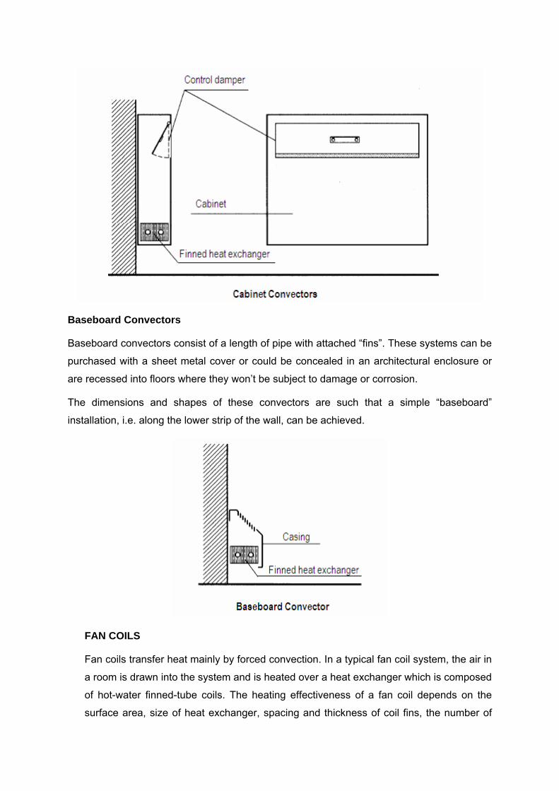
Baseboard Convectors
Baseboard convectors consist of a length of pipe with attached “fins”. These systems can be
purchased with a sheet metal cover or could be concealed in an architectural enclosure or
are recessed into floors where they won’t be subject to damage or corrosion.
The dimensions and shapes of these convectors are such that a simple “baseboard”
installation, i.e. along the lower strip of the wall, can be achieved.
FAN COILS
Fan coils transfer heat mainly by forced convection. In a typical fan coil system, the air in
a room is drawn into the system and is heated over a heat exchanger which is composed
of hot-water finned-tube coils. The heating effectiveness of a fan coil depends on the
surface area, size of heat exchanger, spacing and thickness of coil fins, the number of

tubes and the performance of the fan. The temperature of the entering water as well as
the temperature of the entering air will also influence the heat capacity of the fan-coil.
• The heat output of the fan coil is approximately proportional to the difference
between the entering water temperature and the entering air temperature;
• Increasing the rate of water flowing through the coil will increase the heating
capacity of the fan coil;
• The increase of the air flow rate flowing through the coil will also increase the
heating capacity of the fan coil; and
• A fan coil unit running with lower water temperatures will have the same heat
capacity of another similar heat coil with smaller coil surfaces and/or less tubes.
Fan coil units are constructed with:
• one or two finned coils,
• one or two centrifugal or tangential fans,
• an air filter,
• a condensate collection tray,
• a casing.
They are used for heating and cooling homes, offices, meeting rooms, hotels, hospitals,
laboratories, etc.

Classification
Fan coil units may be classified according to the following criteria:
On the basis of position:
• the floor
• the wall
• the false ceiling
• the ceiling;
According to the type of enclosure:
• cabinet
• recessed into structure
On the basis of the position of the fan:
• on the intake (the fan blows air into the coil)
• on suction (the fan sucks air from the coil)
In relation to the characteristics of the air flow:
• with free flow
• within channels
On the basis of the number of coils:
• with a single coil (in 2 tube systems)
• with a double coil (in 4 tube systems, i.e. in systems in which both the hot fluid
and the cold fluid circulate at the same time)
Installing Fan Coil Units
It is advisable to install fan coil units under a window or along external walls for the
following reasons:
• It is possible to counteract the currents of cold air which form in relation to these
surfaces; and
• The formation of internal surface condensate around the appliance is prevented or
reduced.
UNIT HEATERS
Unit heaters are heat emitters which give off heat by means of forced convection.
Basically they consist of:
• a hot water finned heat exchanger;
• a fan; and
• a casing
Unit heaters are the most commonly used form of heating due to the following reasons:
1. they provide the air circulation needed;
2. they can be used in conjunction with ventilation systems;
3. they are comparably the least expensive;
4. they provide quick response to temperature changes;
5. they are easy to install;
6. they offer inexpensive expansion for additions;
7. they can be used in conjunction with waste heat applications; and
8. they provide snow load protection which facilitates solar gain
Unit heaters can be divided into two categories based on the direction of their air flow,
i.e. horizontal or vertical.
Horizontal Unit Heaters: These are also called “wall” heaters and are used for heating
areas which are not very high. They are provided with horizontal or vertical adjustable
louvers to control the air flow.
Vertical Unit Heaters: These are also called “suspended” heaters and are used to heat
areas with heights of about 20 to 25 meters.
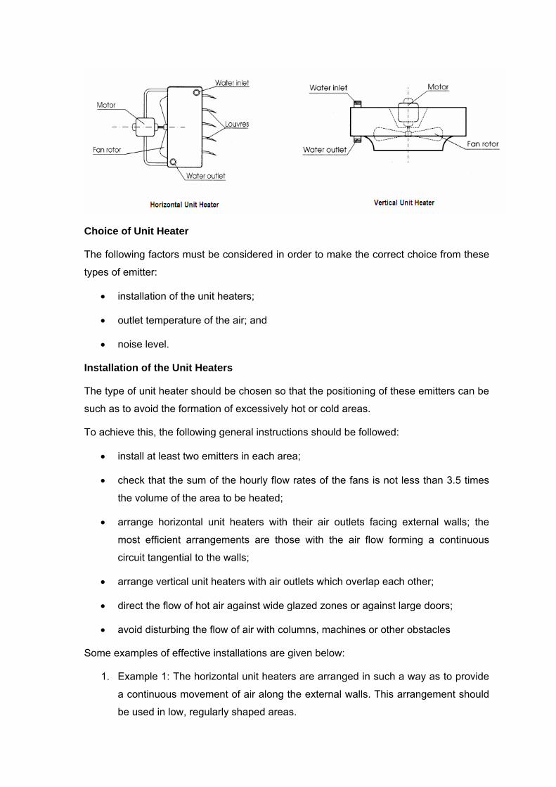
Choice of Unit Heater
The following factors must be considered in order to make the correct choice from these
types of emitter:
• installation of the unit heaters;
• outlet temperature of the air; and
• noise level.
Installation of the Unit Heaters
The type of unit heater should be chosen so that the positioning of these emitters can be
such as to avoid the formation of excessively hot or cold areas.
To achieve this, the following general instructions should be followed:
• install at least two emitters in each area;
• check that the sum of the hourly flow rates of the fans is not less than 3.5 times
the volume of the area to be heated;
• arrange horizontal unit heaters with their air outlets facing external walls; the
most efficient arrangements are those with the air flow forming a continuous
circuit tangential to the walls;
• arrange vertical unit heaters with air outlets which overlap each other;
• direct the flow of hot air against wide glazed zones or against large doors;
• avoid disturbing the flow of air with columns, machines or other obstacles
Some examples of effective installations are given below:
1. Example 1: The horizontal unit heaters are arranged in such a way as to provide
a continuous movement of air along the external walls. This arrangement should
be used in low, regularly shaped areas.

2. Example 2: The horizontal unit heaters are installed along the main axis of
symmetry of the area and their air outlets are directed towards the external walls.
This arrangement should be used to heat particularly wide premises.
3. Example 3: The horizontal unit heaters are installed on the external walls and
their air outlets are directed towards the adjacent or opposite walls. This
arrangement should be used in premises which are not very wide.
4. Example 4: The vertical unit heaters are arranged with their air flows overlapping
each other. This arrangement should be used on premises with heights of more
than 15 ft.
HYDRONIC HEATING – PRIMARY ELEMENTS
The basic hot water heating system consists of the following components:
Hot water heater or boiler; circulating pump; expansion tank; distribution piping; radiators
in the space to be heated (black iron or steel pipes); finned-tube convectors; unit heaters
or under-floor pipes; controls, valves and temperature and pressure gauges (air bleeding
valves, pressure relief valves, and pressure regulators).
1) Boilers, or hot water generators, don’t actually boil the water but simply re-heat it
(typically 140 - 180°F) prior to releasing it to the heat exchangers. Boilers are
generally rated on input and/or output in British thermal units per hour (BTU/h) or in
kilowatts. Boiler output should be adequate to offset building design heat loss, piping

losses from exposure to unheated space and any additional heating needs such as
swimming pools or hot tubs. These systems are often "closed" with virtually no fresh
water makeup. Hot water boilers are often preferred because they normally do not
need an operator or special water chemistry, and they run at higher fuel conversion
efficiencies than steam generators.
There are two basic boiler control strategies, variable temperature and constant
temperature. Variable temperature control is used for systems that heat the living
space. Constant temperature control is used when the system also heats domestic
water, swimming pools or hot tubs.
There are three different boiler types: gas-fired, oil-fired and electricity powered.
Electricity powered boilers are difficult to find and, at this time, are more expensive to
operate than either the gas-fired or oil-fired types. Gas and oil-fired boilers are rated
through the Energy Star program. Boilers that meet or exceed an 85 percent
efficiency rating are labelled as Energy Star compliant. For maximum energy
efficiency, look for boilers displaying the Energy Star logo.
2) Commercial Water Boilers: Commercial water boilers for larger systems come in
many shapes, sizes and construction methods and materials. The two basic boiler
designs for buildings are fire-tube and water-tube.
In fire tube boilers, hot combustion gases pass through tubes submerged in water.
These systems are simple and easy to construct and are generally used in low-
pressure applications. The main components that make fire tube boilers energy
efficient is the four-pass design, the forced-draft design, the heating surface area and
updraft construction.
Four-pass design: The number of passes indicates the amount of time the flue
gases pass through the tubes. It has been proven that the efficiency of the boiler
is directly proportional to the number of passes. The four-pass design is based on
the velocity of the gases being directly proportional to the ratio of the volume of
the gases and the flow area. The flue gas has to maintain high flow velocity. The
temperature of the exhaust gas is lower; leading to an increase of the overall
efficiency of the boiler.
Forced-draft design: The forced-draft design uses a fan to pressurize the
combustion air before it is mixed with the fuel, which improves combustion. This
design provides air in the required quantities and at the proper pressure, thus
reducing excess air.

Heating surface area: Heat transfer is fundamental for efficient and long lasting
equipment. Packaged units can offer a heating surface area of 0.047 m2/kW
which increases the life of the boiler, reduces maintenance requirements and
increases the efficiency of the boiler.
Updraft construction: Updraft construction involves placing the furnace at the
lower end of the boiler and running the gases towards the higher end of the
boiler. The furnace contains the hottest combustion gases and is designed with a
significant clearance from the bottom shell to enable full fluid circulation in the
system. Such a construction offers a safer operation and better combustion.
In water tube boilers, the water is contained in tubes located inside a furnace where hot
flue gases pass over the tubes, heat the water, and then exit out the stack. Small water
tube boilers are usually available in packaged units while larger tubes are assembled in
the field. Packaged water tube boilers, using oil or natural gas, have various designs and
can have any capacity. They are usually categorized according to their burner type: an
atmospheric burner (standing pilot of spark ignition) or a forced convection burner (which
has a higher efficiency and better overall combustion).
For boilers to run at peak efficiency, operators must attend to boiler staging, water
chemistry, pumping and boiler controls, boiler and pipe insulation, fuel-air mixtures, burn-
to-load ratio, and stack temperatures.
3) Circulator, or the circulating pump, is an electrically driven pump that forces water
through the boiler and/or the piping system. Some heating systems have more than
one circulator in order to serve separate areas of the building. The circulator pump is
selected for the flow rate and the head requirements. A pump must develop enough
pressure to overcome the resistance (friction) created in the boiler, piping, fittings,
heat distributing units and other parts of the system. When making your selection, do
not add the static head pressure (due to the height of the system) to the head
pressure rating of the circulator. The following facts may be noted:
• Centrifugal pumps, in the form of wet rotor circulators or three-piece circulators,
are most commonly used in hydronic heating systems.
• There are four possible pump selections: a large and small pump, either of which
can run in high or low speed. Obviously the large pump in high speed offers the
maximum performance, but it would be both the most expensive to buy and the
most expensive to run. The small pump in low speed is at the other extreme.
Again we see the trade-off between initial cost and operating cost ("pay me now
or pay me later").

Pumps can also be placed in parallel or in series. It is a good idea to use two pumps
connected in parallel in case one should fail, or to have a spare on hand.
4) Isolation Valves at all Zones or Flow Circuits are often used as an alternative to
having separate circulating pumps for each different zone in the building. Individual
zone valves are electric and are controlled by their own thermostat so each zone or
room in the home can be individually controlled for comfort and energy savings.
Manually operated valves are sometimes needed to balance the system in multi-
zoned installations, for system shut down, or if a thermostat fails. Valves can usually
be one or two sizes smaller than the line they serve. If the pipe is larger than the flow
requires (as is often the case for bare pipe systems), know the flow rate and select a
valve of the required capacity.
5) Automatic Temperature Control and Zone Control: These are desirable, using
thermostatically controlled flow regulators. Automatic valves regulate the hot water
circuit in each room or zone and are actuated by the thermostat for that room. The
circulating pump usually runs continually and the valves open or close as required.
Alternatively, the pump can be started by a thermostat or aquastat, as one or more
zones calls for heat. Three-speed pumps or pumps equipped with variable speed
drives are also available, which increase or decrease the flow as needed.
6) Relief Valve: Every hot water boiler must have a safety relief valve that will keep the
pressure at or below the boiler’s working pressure. The ASME (American Society of
Mechanical Engineers) code states: “Every hot water heating boiler shall have at
least one officially rated pressure relief valve set to relieve at or below the maximum
allowable working pressure of the boiler. Relief valves shall be connected to the top
of boilers with the spindle vertical if possible. No shutoff of any description shall be
placed between the relief valve and the boiler, or on the discharge pipe between
such valve and the atmosphere.”
The discharge of steam through a relief valve is an emergency condition and places
a critical demand on the valve. Whenever the temperature of the water in the boiler
is about 212°F or above, and the relief valve discharges, the sudden pressure drop
causes the water to flash and to steam. The capacity of the relief valve must handle
this. There is a vast difference between discharging water and discharging steam. A
pound of water occupies 27.7 cubic inches of space. A pound of steam, at
atmospheric pressure, occupies 26.8 cubic feet; over 1600 times more space than
water. Thus, an ASME relief valve is tested and rated on steam, even though it is a

valve for a hot water boiler. The smallest pressure relief valve available is probably
rated at 15,000 BTU/hr, which is also more than adequate.
7) Low Water Cut-Off: Most boiler manufacturers recommend putting low water cut-
offs on hot water boilers. Many local codes will require this. Even though a boiler
may be protected from exploding because it has an ASME relief valve, dry firing can
still ruin it. Most hot water boiler damage can be traced to low water conditions.
There is a misconception that the pressure reducing fill valve will keep a system full
under all circumstances. This is not true. To illustrate the problem, a typical system
will have a pressure reducing fill valve set around 12 to 18 lbs and a relief valve set
to open at 30 lbs and close at 26 lbs. Should the relief valve open to discharge water
due to excess pressure, it is obvious the fill valve won’t make up the water lost.
Without make-up water replacing the loss through the relief valve, a low water
condition can result. There are many other reasons a system can lose water so that
a low water condition will result such as leaks in the boiler, piping, or through the
pump seals. Carelessness, such as draining a boiler for repair and forgetting to refill
the system is yet another common reason for a low water condition. A low water cut-
off will save the boiler by not allowing the burner to come on until the low water
condition is corrected.
Under certain circumstances, a low water cut-off may not be enough protection. A
fuel valve could stick open; contacts could weld closed due to an overload or short
circuit making the low-water cut-off ineffective. The best recommendation to cover all
installations is to use a combination water feeder and low water cut-off. The feeder
portion is usually capable of feeding water into the boiler as fast as it can be
discharged through the relief valve. While the feeder cut-off combination will add to
the cost of an installation, when compared to the cost of replacing a boiler, it is
“cheap” insurance. Remember, codes are minimum requirements that must be
complied with. It is always good practice to exceed the code requirements, especially
where safety is a concern.
8) Expansion tanks are used as a reservoir or overflow tank. Water expands about 4%
as it heats from room temperature to near boiling. The expansion tank is an essential
component of the hydronic heating system used to accommodate an increased
volume of water in order to avoid damage and accidents due to high pressure. The
expansion tank contains a quantity of air that is compressed as the volume of water
rises in the system. In essence, the expansion tank performs two key functions: 1)
accept the extra water produced by heating the water in a sealed system and 2)
prevent the circulator from changing the static pressure in the sealed system. The
three parameters to take into consideration when designing an expansion tank are its
location, its height and its volume. As a general rule, the expansion tank should also
be located near the inlet port of the circulator and the volume of the tank should not
be larger than the calculated volume value.
Expansion tanks are sized from the volume of water in the loop and the difference
between the maximum and minimum operating temperatures. Generally the required
volume is less than 10% of the system volume. System water volume and
temperature determine tank size. The compression tank acts like a spring on the
system, keeping pressure on it at all times.
• If the tank is too small, or becomes waterlogged, the relief valve will open when
the boiler is heating and will discharge water. When the heating cycle is over, the
water will cool, system pressure will drop, and the feed valve will open and feed
water until system pressure is back to “normal”. On the next call for heat, the
water will again expand, causing the relief valve to open. The cycle will repeat
over and over until the small tank is replaced, another expansion tank is added,
or the waterlogged tank drained and properly refilled with the correct air and
water charge.
• If the tank is too large, the system pressure increase may not be enough as the
system heats up and approaches boiling, especially at the high point of the
system where low static head exists. Proper compression tank sizing is very
important for trouble-free system operation, whether it is a pre-charged tank with
a bladder separating the water and air, or a standard expansion tank.
9) Air elimination devices should be installed at each high point in the hydronic
system where air can gather. Trapped air must be expelled from the heating system
to ensure optimum heating performance and to prevent noisy operation, blockage or
even complete damage to the system.
Manual air vents at high points, automatic air vents, float-type air vents, air purgers
and micro-bubble absorbers are used to solve the problem. There are two basic
types of air vents: automatic and manual. Automatic air vents come in two styles:
float type and fiber disc type.
• Float vents have a float attached to a valve, all contained in a shell. When
the shell is full of water, the float keeps the valve closed. When enough air
accumulates in the shell, the float drops causing the valve to open and the air
to pass out, until water again fills the shell causing the valve to close.
• Fiber disk type automatic vents are physically very small; the same size as
manual “loose key” or “coin” vents. They use special discs that swell when
water touches them. As air accumulates and replaces the water around the
discs, the discs dry out, shrink, and open a small vent port.
• The best air vents are the manual vents which require a small key to open or
close them. These are just a small needle valve, metal to metal seat, and are
virtually indestructible and cheap. Their only drawback is that they must be
manually opened and closed. Air vents for residential heating systems
typically have a 1/8" NPT (National Pipe Thread) connection and require no
further sizing.
10) Heat transfer devices such as radiators, convectors, fan-coil units and radiant floors
transfer the heat from piped water to the living space.
11) Heat exchangers are the elements in the hydronic system that transfer heat to the
piped water, or in the case of snow melting systems, the heat is transferred to an
anti-freeze solution.
12) Mixing valves blend cooler return water with hot boiler water to obtain the desired
thermostat temperature.
13) Controls: Standard low-voltage or newer programmable electronic thermostats can
be used to provide temperature control for the hydronic system. Thermostats are
usually connected to - and control the zone valves. When the valve is fully open, an
end switch on the zone valve turns the boiler and circulator on. Thermometers and
pressure gauges are handy for balancing the system and also to monitor the
efficiency of the system. Pressure gauge cocks and thermometer wells shall be
installed at appropriate locations to make the routing checks.
14) Pressure regulator: The pressure regulator which is actually a pressure reducing
valve must be provided on the cold water supply connection. It is used to fill the
system initially and will add water when system pressure falls below the valve setting.
The standard factory setting is usually 12 lbs. This setting is the correct setting for a
static height up to about 18 feet; appropriate for most two-story buildings. For higher
static heads, the valve can be adjusted up to 25 lbs. Most systems work best under
a moderate pressure of about 15 PSI (100 kPa) for better circulation and to avoid
vapor locks (just like automobile systems).
A 0-100 PSI pressure gage would be specified if the water tank is connected to the
domestic water supply, since most city water systems operate in that range. If it is a
stand-alone loop, specify a 0-30 PSI pressure gage, since residential heating
equipment is generally required by ASME Pressure Vessel Code to operate in that
range.
15) Piping materials for the hydronic system will vary depending on how the system is
used and installed. Copper piping is typically used to distribute the hot water
throughout the system; however, if the piping is embedded in concrete it may be
made of iron, steel, synthetic rubber or plastic. Take changes in pipe size into
account when choosing supports and planning layout. Provide sleeves or adequate
clearance where pipes pass through walls or floors. Pipe supports should allow
movement. Allow for expansion at the end of and along pipe line, or loop by stopping
short of the end wall. For a 100°C change in temperature, steel expands 0.12% in
length; various plastics expand 5 to 15 times as much.
16) Draining and Venting: Both are facilitated if heating lines slope uniformly to one end
(or one point). Install drain cocks at the low points and air vents at the high points.
One of each may be all that is required for simple systems; others may require
several.
17) Pipe insulation is used to prevent heat loss and to ensure heat is delivered to the
living space where it is required. Pipes running through unheated areas, such as
crawlspaces, should be insulated with moulded fibreglass pipe insulation.
18) Antifreeze and Corrosion Protection: This protection is important. Antifreeze
should be used if there is any danger of freezing. Use an ethylene glycol solution
specially formulated for hot water heating systems. This contains corrosion inhibitors
to maintain long-term performance of systems and components. Check the antifreeze
solution every year and add inhibitor if needed.
SIZING HYDRONIC SYSTEMS
Hot water heating systems have been traditionally designed for a supply temperature of
180 to 200°F with a 20°F temperature drop (delta T). Equipment manufacturer's
selection data are normally indexed to these temperatures as are the practices of many
design professionals.
Flow Rate: The required flow rate (in gallons per minute or GPM) is based on the
quantity of energy that must be delivered. The volumetric flow rate in a heating system
can be expressed by the basic equation:
q = h / (cp * ρ * ∆T)

Where,
• q = volumetric flow rate, (gal/min)
• h = heat flow rate, (BTU/h)
• cp = specific heat capacity, (BTU/lb F)
• ρ = density, (lb/ft3)
• ∆T = temperature difference (°F)
The basic equation can be modified for the actual units (SI or imperial) and the liquids in
use.
For water with a temperature of 60°F, the flow rate can be expressed as:
q = h (7.48 gal/ft3) / ((1 BTU/lb F) (62.34 lb/ft3) (60 min/h) ∆T) or
q = h / (500 * ∆T)
Fluid Velocity: The acceptable range for water velocity in most applications is between
three and seven feet per second (3-7 fps). Velocities lower than 3 fps represent large
diameter pipes that are uneconomical to install, and velocities higher than 7 fps
represent too small pipes that will cause large pressure drops and uneconomical sizing
of circulator pumps. Going outside of this acceptable design range can also cause
problems with air entrapment in the water (if too slow) and pipe erosion and noise (if too
fast).
Pipe Size: The pipe size is determined from the standard selection charts based on the
equation q = A * V, where A = area of the pipe, π * d2/4, and V is the velocity of flow in
fps. When the two parameters (GPM and velocity range) are fixed, the optimum pipe
diameter can be selected. For example, if a system requires 90 GPM, we can select
either 2-½" diameter pipe at 6 fps or 3" diameter pipe at 4 fps, both within the acceptable
velocity range. Most flow rates will offer a choice between a couple of pipe diameters
within the acceptable velocity range.
Distributing the hot water
There are four basic piping systems used in hydronic heating systems to distribute
heated water:
1) One-pipe series loop systems are the simplest version and use a single pipe that
runs through a series of rooms. Heating devices are connected to the pipe wherever
they are needed but no individual room control is possible within the loop. It is

possible to divide this single loop into a series of zones using zone valves to control
temperature within specific areas of the home. Each loop in a zone valve controlled
loop should have shut-off and drain valves in the boiler room for isolation in the event
of a system leak.
2) One-pipe systems with diverting tees are similar to the series loop systems in that a
single pipe is used but the heating units are installed in side circuits off the main pipe.
In this system, a special pipe fitting is installed to force the heated water out of the
main pipe to a heating device prior to returning the water back to the main pipe. In
this system a thermostat control can be installed in each room; however, individual
rooms may not reach the desired temperature setting due to water cooling along the
way.
3) Two-pipe direct return has the fluid returned directly to the boiler by the shortest
path. The hot water delivered to the first radiator is also the first to return to the boiler.
This progresses through the circuit so that the last radiator is the last to return its
cooler water to the boiler. With the direct return, units closest to the boiler tend to get
too much flow and those on the end of the line get too little. There is a tendency for
the radiators closest to the boiler to short-circuit the water so the units farther away
do not get proper circulation. This system should be installed using balancing valves
and carefully balanced.
4) Two-pipe reverse return: In a reverse return loop, the water in the return runs
parallel with the supply pipe until the last coil has been supplied. In this system, the
first radiator to be fed hot water has the longest return, and the last radiator to be fed
has the shortest return. It is more expensive to install because more piping is
required than the two-pipe direct return system, but it functions much better because
it results in more uniform or balanced flow as long as the supply and return drops
have the same size and length.
The concept of direct return vs. reverse return is further described below.
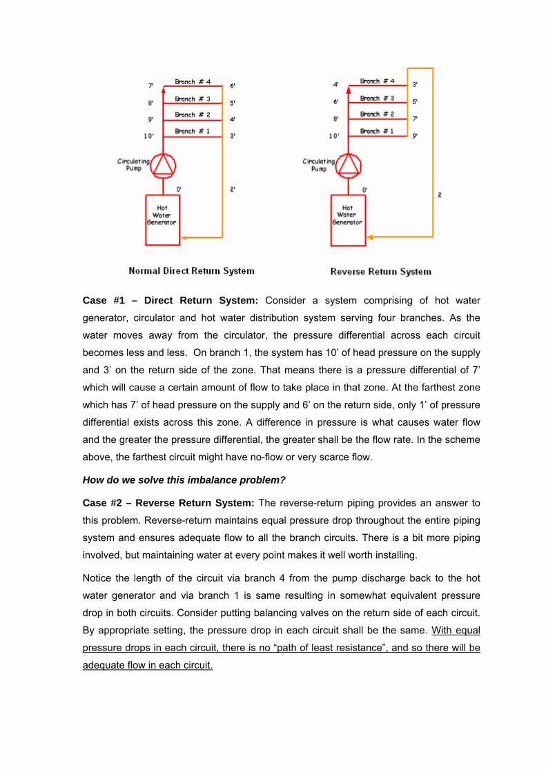
Case #1 – Direct Return System: Consider a system comprising of hot water
generator, circulator and hot water distribution system serving four branches. As the
water moves away from the circulator, the pressure differential across each circuit
becomes less and less. On branch 1, the system has 10’ of head pressure on the supply
and 3’ on the return side of the zone. That means there is a pressure differential of 7’
which will cause a certain amount of flow to take place in that zone. At the farthest zone
which has 7’ of head pressure on the supply and 6’ on the return side, only 1’ of pressure
differential exists across this zone. A difference in pressure is what causes water flow
and the greater the pressure differential, the greater shall be the flow rate. In the scheme
above, the farthest circuit might have no-flow or very scarce flow.
How do we solve this imbalance problem?
Case #2 – Reverse Return System: The reverse-return piping provides an answer to
this problem. Reverse-return maintains equal pressure drop throughout the entire piping
system and ensures adequate flow to all the branch circuits. There is a bit more piping
involved, but maintaining water at every point makes it well worth installing.
Notice the length of the circuit via branch 4 from the pump discharge back to the hot
water generator and via branch 1 is same resulting in somewhat equivalent pressure
drop in both circuits. Consider putting balancing valves on the return side of each circuit.
By appropriate setting, the pressure drop in each circuit shall be the same. With equal
pressure drops in each circuit, there is no “path of least resistance”, and so there will be
adequate flow in each circuit.

Note that the two-pipe systems are more expensive than either of the one-pipe systems
but water in each of the pipes travels shorter distances, returns to the boiler more quickly
and allows greater heat control in individual rooms or zones.
Control Strategies
When a boiler is used for space heating, the simplest control strategy is to have the
thermostat control the burner and circulator together. This easily adjusts the heat to your
needs and provides the lowest operating costs. Programmable thermostats can be
purchased and set up with the boiler and circulator to allow you to control the time and
temperature settings of your heating system. A programmable thermostat is one of the
most energy efficient items you can add to your heating system.
A second control strategy is to always keep the boiler hot and have the thermostat turn
the circulator on and off. Operating costs for this strategy will be higher due to continual
heat losses.
A third method of space heating is to adjust the boiler temperature to compensate for the
temperature outside on the north side of the house. In this system, an externally
mounted thermostat records outdoor temperatures and an internal thermostat adjusts
interior zone valves to comfortable heating levels. This method is more energy efficient
than the other temperature control strategies.
If your boiler is also used to heat domestic water it must be maintained at full
temperature, even when living space heating isn’t needed. This leads to increased
operating costs from high stand-by heat losses. Separate water heating is recommended
for energy efficiency.
Installation hints
1. Install a programmable thermostat with the heating system. Set it to turn heat
down when your home is empty and to turn the heat up before you return home.
2. Install extra heating capacity in the bathroom, most people prefer a warmer
bathroom.
3. Install a floor heater or recessed tube piping in front of glass patio doors to offset
the chill caused by the large glass area. Allow at least 20 cm between the heater
and the window.
4. Install a return air grille in the floor at the opposite side of the room from the
heating device to improve cold air removal.
5. Clean heating devices regularly to remove dust and keep air circulating properly.
6. Install hot water to anti-freeze heat exchangers and piping systems under steps,
sidewalks and driveways to melt snow and ice, improving safety outside your
home during winter.
7. As a minimum, bedrooms should be zoned separately from living and dining
areas.
8. Rooms with southern exposure should be zoned separately from those with other
exposures.
9. Radiant floors have lower water temperature requirements than convection units
and these must be on separate zones.
System Startup
Most air problems can be eliminated by careful design, good maintenance, and proper
initial startup of the system. The most often overlooked part of a forced hot water system
is proper startup. Once a system has been installed, flushed, and filled to the proper
static head, the boiler should be fired and slowly heated to at least 225°F water
temperature and held there for about one-half hour. This will liberate the entrained air in
the water and send it to the expansion tank. The hotter the water, the more air it will
liberate. The circulating pump(s) should be off during this initial heating. Now, allow the
boiler to cool to normal operating temperature and start all circulators and open all the
zone valves, if used. Again, run the water temperature back up to at least 225°F and
circulate all the water for 15 to 30 minutes. This will drive most of the air out of the fresh
water, and as long as there are no leaks in the system, air problems will be prevented.
Anytime the system is drained, say for some repairs, and then re-filled, the startup
procedure should be repeated.
HOT WATER RADIANT FLOOR HEATING
Radiant floor heating is accomplished by circulating hot water through lines of plastic
pipe, either placed in sand below the floor, or right in the concrete itself. Most typically, a
thermoplastic or synthetic rubber tube is used on 6-12” centers, cast in the center or
placed under the slab. Warm water is pumped through these tubes from manifolds
placed at an accessible location, usually at one end of the space.
Radiant floors transfer heat through direct conduction, direct radiation and gentle
convection. The combination of the three modes of heat transfer makes this one of the
most comfortable systems. A hydronically heated slab floor provides very even
temperatures and is the most popular and cost-effective system for heating-dominated
climates. An advantage to using this type of system is that it is very energy efficient.
Radiant heat floors evenly heat rooms using lower water temperatures than other
hydronic systems, thus reducing energy consumption. They offer benefits such as
thermal comfort, energy efficiency, quietness, cleanliness, versatility, durability and
minimized stratification effect. The main disadvantage is their slow response time
compared to other hydronic systems.
Radiant floor systems can be installed in one of three ways:
• Slab-on-grade system
• Thin-slab system (lightweight concrete, gypsum under layment)
• Dry System (above deck system, below deck system)
Radiant Heating Design Principles
Systems are designed using the same principles outlined for hot water space heating.
Unlike systems that heat air, a heated concrete floor slab should be controlled by
monitoring the slab temperature directly. A heated concrete floor slab can usually
provide 30-50% of the total conductive heat loss of a space. Most often, another type of
a hot water system (bare pipes, finned pipes, unit heaters or other system) is installed to
supplement the floor system on cold nights.
Most of the equipment is the same: heater or boiler, circulating pump, expansion tank,
valves and controls. The following comments are specific to floor heating:
Water temperature
For floor heat, hot water temperature can be much lower than for space heating; 100 -
140°F rather than 190°F. The floor temperature of a large area is best controlled by
regulating the water temperature, rather than by starting or stopping the flow. Control of
small sections may be more precise and adjustable if line thermostats regulate flow to
each section. Water temperature will be 50-60°F warmer than the floor when pipes are
placed in the concrete and about 75°F warmer when they are in the sand below.
It is often useful to know the floor temperature. One way to do this is to make
thermometer wells in the concrete. An ordinary thermometer (or electronic temperature
probe) in contact with the floor can measure temperature directly. It works best if covered
with small slab of foam insulation so it is kept at floor temperature. Cut a small groove in
the insulation if it is over the thermometer.

Piping
Usually, this is plastic. Polybutylene pipe made for hot water service is recommended.
Higher strength 125 PSI (850 kPa) polyethylene can also be used, as well as soft copper
tubing. Connections should be made outside the floor using double stainless steel
clamps. Floor heat may require long runs of smaller pipe, thus pipe size must be
adequate for the flow. For complete situations, get expert advice for checking flow and
pressure loss, otherwise, the following is a safe guide for a minimum pipe size, although
larger pipes can be used:
Pipe Loop
Lengths
Pipe
Diameter
Up to100 ft 0.5”
Up to 200 ft 0.75”
Up to 325 ft 1.0”
Up to 500 ft 1.25”
Water flow should be higher than for space heat to keep the temperature more uniform.
Use a temperature drop of 10-15°F for calculating flow rates.
Radiant floor heating has a number of advantages:
1. Warm floor dries quickly
2. Snow and ice melt faster
3. Heating is very uniform
4. Floor has high thermal mass, thus retains heat for a long time
It also has some disadvantages:
1. Relatively high cost compared to other methods
2. System can be damaged if the floor cracks
3. Slow to react to sudden changes in demand (large door opened, large cold
machine brought in)
4. Not suitable for occasional use
5. By itself, may not maintain temperature during the coldest weather
6. The most serious drawback to floor heat is slow reaction time. You may find it
necessary to have a supplementary space heater (separate unit heater or
furnace) for quick response when cold-weather servicing is critical.
System Design
The best floor temperature is 77 - 86°F; warmer floors are uncomfortable and cooler
ones are less effective. The amount of heat transferred from the concrete floor depends
on both floor and air temperatures. Heat input to the floor will depend on the inlet water
temperature, pipe spacing and water flow, provided that the heating unit has enough
capacity to keep up to the floor heat loss.
Heat output from floor to air is given by the following equation:
h = 2.11 * (Tf - Ta)
where,
• h = heat output from the floor, BTU/sq-ft
• Tf = floor slab temperature, °F
• Ta = room air temperature, °F
For a floor at 86°F and air temperature of 58°F, heat output would be 2.11 x 28°F = 59
BTU/sq-ft. As the building cools below 58°F, the heat output will increase. Design for 60
BTU/sq-ft and size the heating unit slightly larger to account for system losses.
It is possible to get by with a smaller heating unit, down to about 50 BTU/sq-ft, if cooler
floors are acceptable. This heat output will keep a reasonably well-insulated shop at 50 -
58°F but does not have extra capacity for reserve heat. It is not feasible, however, to
obtain greater capacity from the floor system, since this would require a floor
temperature too high for comfort. The system will have to be larger if auxiliary unit
heaters are supplied from the same boiler system.
Water flow and pump capacity are calculated as outlined earlier; using equation:
q = h / (500 * ∆T)
where,
• q = water flow rate (gal/min)
• h = heat flow rate (BTU/h)
• ∆T = temperature difference (°F)

The ∆T is usually taken as 9-16°F to maintain uniform conditions. Floor heating pipe is
usually placed in loops running from a supply and back to a return header. Flow through
each loop, for the purpose of checking pressure drop and sizing valves, is thus the total
flow divided by the number of loops. Pipe may also be laid out in a continuous spiral
around the building but this will require larger pipe owing to the longer loop length. The
header system is normally of steel pipe, with T-fittings or nipples welded on for attaching
the floor lines. The header should be sized for the total water flow in the system. Valves
are recommended on each floor line to balance or control flow; one on the supply and
another on the return are best in case one loop springs a leak.
Example:
Design a floor heating system for a 32’ x 50’ room. Floor area inside the foundation is
about 30’ x 48’ = 1440 sq-ft. Calculate system size based on 70 BTU/sq-ft heat input.
Solution
Room floor area = 1440 sq-ft
1) Calculate system size based on 70 BTU/sq-ft heat input.
Total Heat input = 70 BTU/sq-ft x 1440 sq-ft = 100800 BTU (or ~ 30 kW capacity)
2) Determine flow rate for an inlet-outlet hot water temperature change of 10°F across
the system
q = h / (500 * ∆T)
q = 96600 / (500 * 10)
q = ~ 20 GPM
3) Determine number of loops and water quantity per loop
Each loop is about 100 ft ( ~2 x 48’) long, thus ¾” pipe will be adequate (Note: double
loops of 184 ft length could be run to reduce valves and connections).
Room width = 30 ft
Pipe spacing = 1.5 ft
Number of lines = 30 / 1.5 = 20
Therefore, use 20 lines or 10 loops
Water flow in each loop = 20 / 10 GPM = 2 GPM
4) Size the header system:
For a flow of 20 GPM, 2” (50 mm) pipe is more than adequate.

5) Estimate the volume of the system
1000 ft of ¾” floor pipe x 0.025 gallons per ft = 25 gallons (i.e. at a 100 ft loop x 10 loops;
the ¾” pipe has a holding capacity of 0.0.25 gallons per ft of pipe).
60 ft of 2” mm header x 0.16 gallons per ft = 9.6 gallons (i.e. at 2 x 30 ft of supply &
return header; the 2” pipe has a holding capacity of 0.16 gallons per ft of pipe).
Boiler unit volume (estimated) = 5 gallons
Total = 39.6 gallon
Minimum expansion capacity required is 5% of 39.6 gallon = 1.98 gallon; obtain an
expansion tank with at least 2 gallon net expansion capacity.
Heated Concrete Slab Floors Installation
Floor heating pipe may be laid either in sand layer below the concrete or directly in the
concrete. The former is easier to do and safer from leaks caused by floor cracks. The
latter is slightly more efficient. When concrete cures it shrinks, causing natural cracks to
occur. Where pipe is placed in the floor, reinforcing is required to reduce cracking to
small hairline cracks. This reinforcing can benefit any floor, but less is needed if control
joints are part of the floor design (which cannot be done with in-floor pipes). To control
cracking, the recommended cross-section area of reinforcing steel is 0.16% of the cross-
section area of the floor slab. When selecting a heated concrete slab floor, it is important
to consider many factors:
1. The tubing you use must last as long as the concrete itself, so make sure it has
been developed for your specific purpose.
2. The type of concrete, and the way it is mixed will have a long term effect on the
durability and usefulness of your floor.
3. For floor reinforcement, there are three basic methods used: re-bar, re-mesh and
“fiber-mesh”. The latter is an additive to the wet concrete and reportedly can offer
the most integrity and longevity. Spend some time researching the best means of
reinforcement for your project. Remember that you will need to secure your
heating tubing to something and a reinforcement mesh might be the best choice.
4. Insulation: It cannot be stressed enough that a heated concrete slab floor should
be insulated around the perimeter and as deep as the frost line in your area.
Some reports indicate that up to 50% of your heat can be lost out the perimeter of

a heated slab if no below grade insulation is installed. The best type of insulation
to use is one of the extruded styrene boards, usually 1.5 - 2” inches thick.
5. Engineering: A good design and plumbing plan are the keys to a well designed
heated concrete slab floor. A well designed system will include an appropriate
boiler and pump sized to handle the load. Also important is a means of balancing
the flow of hot water to achieve even floor temperatures.
The factors to take into consideration during the design of a radiant floor system are:
a. dimensions of the space
b. space heating loads
c. ease of tube installation
d. location of manifold stations
e. position of control joints
f. zoning of the spaces
g. type of floor covering
h. length of pipe circuits
i. horizontal spacing between the tubes
j. position of exterior walls
k. possibility of driving fasteners in the floor
The following guidelines should be considered as well:
a. route the hottest fluid first along the exterior walls of a room
b. maximize straight runs and minimize bends and corners
c. limit the length of the circuits with respect to the tubes
d. design the circuit for room-by-room zoning
e. limit the passage of pipes through control joints
f. place the tubes according to the grid (slab-on-grade)
g. avoid tube crossover
h. avoid tube perforation

SECTION- 6 ELECTRIC HEATING
Electric furnace using resistance heating converts nearly 100% of the energy in the
electricity to heat. From energy management and environment conservation point of
view, electric heating is not a recommended choice for heating. Since most electricity is
produced from oil, gas or coal generators that convert only about 30% of the fuel’s
energy into electricity and after accounting losses due to transmission and distribution,
converting electricity back to heating doesn’t make sense.
Electrical Resistance Space Heating Equipment
Electric resistance heat can be supplied by centralized forced-air furnaces, zone unit
heaters and heat pumps.
Central Electric Furnace
In a central electric furnace, air is blown over electric heating coils and then distributed
through the ductwork. This type of furnace is much simpler than a fuel-fired one,
because no combustion air or exhaust is needed. Therefore, these units have an
efficiency rating of 100%, meaning that all of the heat created goes into heating.
However, this figure can be misleading. A lot of energy is lost producing and transporting
electricity to the house, and it shows up on the energy bill. As with all forced-air systems,
leaky ducts in a poor distribution system can lead to hefty additional heat losses.
Electricity rates vary, but in most places a central electric furnace is the most expensive
type of heating system to run.
Zone heaters distribute electric resistance heat more efficiently than electric furnaces
because you set room temperatures according to occupancy. In addition, zone heaters
have no ducts that can lose heat before it reaches the room. However, electric furnaces
can accommodate central cooling easier than zone electric heating, because the air
conditioner can share the furnace's ducts.
Typical zone electrical space heating equipment include baseboard units, wall units, unit
heaters, portables, ceiling units, and insulated conductors embedded in the ceiling or
floor. Here are several options for electric resistance space heaters.
1) Baseboard Heaters: Sometimes called electric strip heaters, baseboard radiation is
a fairly common heat source and heating system. Compact heating elements
enclosed in protective and decorative linear housings are permanently installed along
the lower part of one or more room walls; typically near the intersection with the floor.
Room air heated by the resistance element rises and is replaced by cooler room air,
thereby establishing a continuous convective flow of warm air while in operation.
Although various control schemes are possible, baseboards are individually
controlled. Electric baseboards are cheap to install but expensive to run, although if
used to heat only occupied rooms, they can be less costly than a central electric
furnace.
2) Wall Units: These heaters may be flush-mounted or recessed, and use a radiant or
ceramic panel, heating coils, or other form of heating element. They come with or
without a built-in fan and thermostat. These units are often used for spot heating in
areas such as building entrances and where higher temperatures are needed.
3) Ceiling Units: These are similar to the wall units in type, but designed for ceiling
installation. Units may include lighting devices (e.g., restrooms).
4) Deep Heat Systems: These systems are used in northern climates where it may be
effective to bury electric heaters in a sand bed beneath the concrete floor of the
warehouse, commercial space, or garage. These large thermal masses can often be
heated during the off-peak period to provide economical space heat during occupied
hours. Since most people are more comfortable when their feet are warm, these
systems have also been reported to provide very pleasant work environments even
in the most extreme of weather conditions.
5) Duct Insert Heaters: Heating elements are inserted in the ducts of forced air heating
systems, either at the fan location or near supply air outlets. Heaters may be step-
controlled in accordance with the amount of heat needed. Automatic safety cut-offs
interrupt current on either over-temperature of unit or fan failure.
6) Heating Cables: These are insulated resistance heating elements manufactured in
various lengths and wattage's and are suitable for installation in the ceiling plaster or
in/under concrete slabs. This method of heating evenly distributes the heat source
and produces a low temperature radiant heat surface. This method has been used in
large open buildings such as warehouses, garages, hangars, etc.
7) Unit Heaters: These heating elements are used with a fan or blower to force air into
the conditioned space. Certain types are classified as heater-ventilators and perform
the function of both controlled heating and ventilating. These units have been used
primarily in schoolroom heating, but can be used for many commercial or industrial
applications where ventilation is required.
8) Electrical Tubular Heaters: These are steel or aluminum tubes usually round or
oval in section. They consist of an electrical heating element which extends from end
to end and is surrounded by air. The surface temperature is about 80°C. A single
tube at 50mm diameter has an output of about 180 Watts per meter length and tubes
may be mounted in banks, one above the other, for higher outputs. An electrical
skirting heater with an output of 400 Watts per meter run is typical of some
installations requiring background or low level heating. Tubular heaters are used in
churches, under pews, in greenhouses, conservatories and foyers. They can be
placed at the bottom of high windows to prevent downdraughts of cold air or be set to
prevent frost in greenhouses or conservatories.
9) Radiant Heating: Instead of circulating heat by moving the air in the room, a radiant
system heats objects and people. There are several types of electrical radiant
heaters:
• Infrared Radiant Heaters: These heaters generate infrared radiation, heating all
objects in their "line of sight," or radiation path. The electrical elements used are
similar to those fitted to luminous fires but, for a given rating, are commonly
longer as shown below, and arranged to operate at about 900°C. Equipment is
available with either metal sheath enclosed element, quartz tubes and reflector
lamps. They are all used with a directional reflector. Wall or ceiling models of
these are suitable for kitchens and bathrooms with ratings up to 3 kW. Infrared
heating is used in areas where heating the entire space through convection
would be difficult or expensive in comparison to keeping people comfortable such
as warehouses, garages, etc.
• Quartz Lamp Heaters: The elements of this type of heater operate at about
2000°C and consist of a tungsten wire coil sealed within a quartz tube containing
gas and a suitable halide rating of elements about 1.5 kW. These are used in
large spaces either where the requirement is intermittent or where only local
areas require spot heating.
• High Temperature Panels: These consist of either a vitreous enamelled metal
plate or a ceramic tile behind which a resistance element is mounted within a
casing. Panels of this type operate at a temperature of about 250°C, have ratings
in the range 750 W to 2 kW, and are normally used in washrooms in industrial
settings. These low-density radiant heaters can be mounted on walls or ceilings
to provide spot heating.
Heat Pumps
Heat pumps are designed to move heat from one fluid to another. The fluid inside the
home is air and the fluid outside is either air (air-source) or water (geothermal). In the
summer, heat from the inside air is moved to the outside fluid. In the winter, heat is taken
from the outside fluid and moved to the inside air.
A heat pump is an electrical device that functions by moving (or pumping) heat from one
place to another. Like a standard air-conditioner, a heat pump takes heat from inside a
building and dumps it outside. The difference is that a heat pump can be reversed to
take heat from a heat source outside and pump it inside. Thus a heat pump can be used
for both summer cooling and winter heating cycles. Note the following facts:
1. In the heating mode, heat pumps are far more "efficient" at converting electricity
into usable heat because the electricity is used to move heat, not to generate it.
2. Because they move heat rather than generating heat, heat pumps can provide up
to 4 times the amount of the energy they consume.
3. If you heat with electricity, a heat pump can trim the amount of electricity you use
for heating by as much as 30 to 40%.
4. High-efficiency heat pumps also dehumidify better than standard central air
conditioners, resulting in less energy usage and more cooling comfort in the
summer months.
The heat pumps are divided into two major groups: air source (air-to-air) systems which
draw heat from the air, and ground source (earth energy) systems which draw heat from
the ground or underground water.
Air Source Heat Pump
The most common type of heat pumps is the “air-source heat pump” which uses outside
air as the heat source during the heating season and the heat sink during the air-
conditioning season.
Most heat pumps operate at least twice as efficiently as conventional electric resistance
heating systems. They have typical lifetimes of 15 years compared to 20 years for most
furnaces.
Heat pumps use the vapor compression cycle to move heat. A reversing valve allows the
heat pump to work automatically in either heating or cooling mode. The heating process
is as follows:
1. The compressor (in the outside unit) pressurizes the refrigerant which is piped
inside.
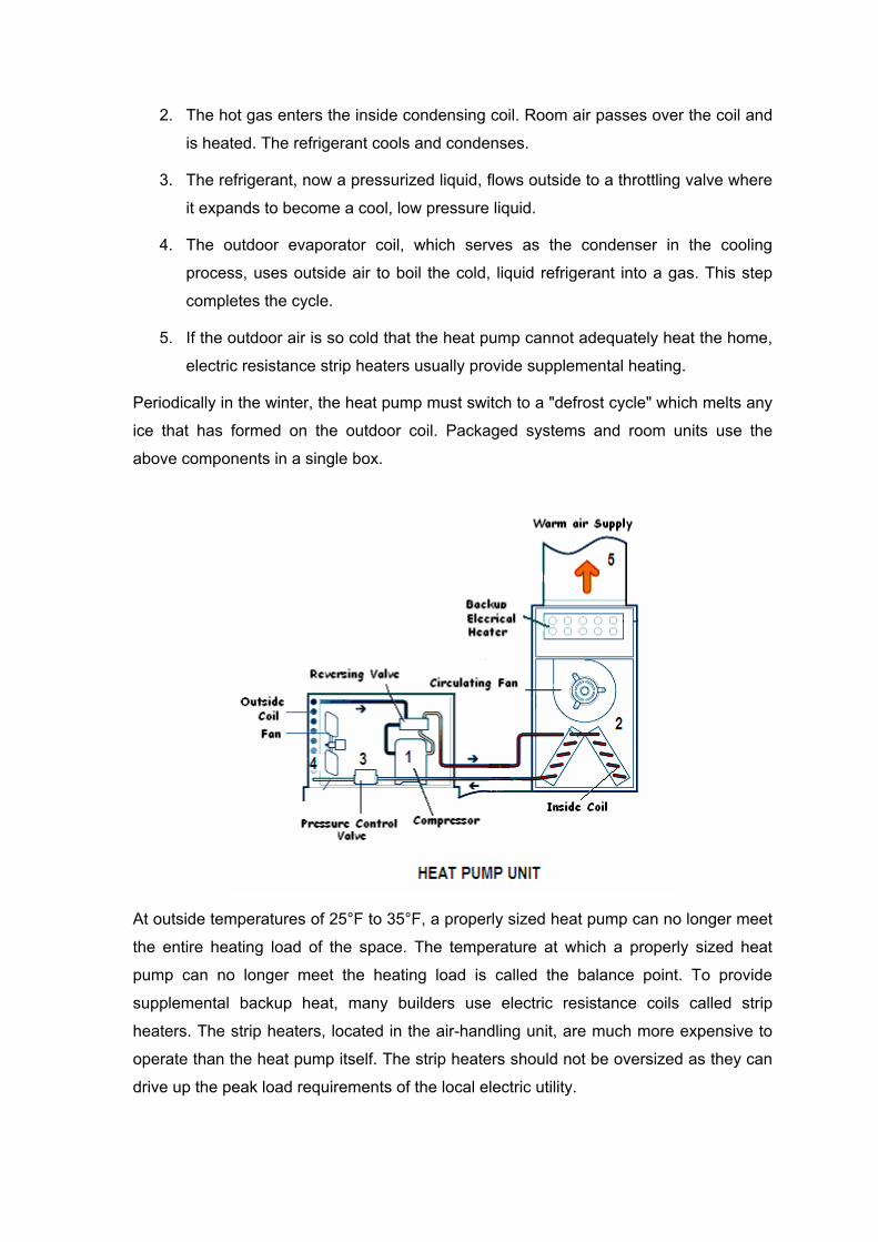
2. The hot gas enters the inside condensing coil. Room air passes over the coil and
is heated. The refrigerant cools and condenses.
3. The refrigerant, now a pressurized liquid, flows outside to a throttling valve where
it expands to become a cool, low pressure liquid.
4. The outdoor evaporator coil, which serves as the condenser in the cooling
process, uses outside air to boil the cold, liquid refrigerant into a gas. This step
completes the cycle.
5. If the outdoor air is so cold that the heat pump cannot adequately heat the home,
electric resistance strip heaters usually provide supplemental heating.
Periodically in the winter, the heat pump must switch to a "defrost cycle" which melts any
ice that has formed on the outdoor coil. Packaged systems and room units use the
above components in a single box.
At outside temperatures of 25°F to 35°F, a properly sized heat pump can no longer meet
the entire heating load of the space. The temperature at which a properly sized heat
pump can no longer meet the heating load is called the balance point. To provide
supplemental backup heat, many builders use electric resistance coils called strip
heaters. The strip heaters, located in the air-handling unit, are much more expensive to
operate than the heat pump itself. The strip heaters should not be oversized as they can
drive up the peak load requirements of the local electric utility.

A staged, heat pump thermostat can be used in concert with multistage strip heaters to
minimize strip heat operation. To overcome this problem, some houses use a dual-fuel
system that heats the home with natural gas or propane when temperatures drop below
the balance point.
Air-source heat pumps should have outdoor thermostats which prevent operation of the
strip heaters at temperatures above 35°F or 40°F. Many mechanical and energy codes
require controls to prevent strip heater operation during weather when the heat pump
alone can provide adequate heating.
The proper airflow across the coil is essential for the efficient operation of a heat pump.
During installation, the airflow rate must be checked to ensure that it meets the
manufacturer’s recommendations.
Air Source Heat Pump Efficiency
The heating efficiency of a heat pump is measured by its Heating Season Performance
Factor (HSPF), which is the ratio of heat provided in BTU per hour to watts of energy
used. This factor considers the losses when the equipment starts up and stops, as well
as the energy lost during the defrost cycle.
New heat pumps manufactured after 2005 are required to have an HSPF of at least 7.7.
Typical values for the HSPF are 7.7 for minimum efficiency, 8.0 for medium efficiency,
and 8.2 for high efficiency.
Variable speed heat pumps have HSPF ratings as high as 9.0, and geothermal heat
pumps have HSPFs over 10.0. The HSPF averages the performance of heating
equipment for a typical winter in the United States, so the actual efficiency will vary in
different climates.
To modify the HSPF for a specific climate, a modeling study was conducted and an
equation was developed that modifies the HSPF, based on the local design winter
temperature. In colder climates, the HSPF declines and in warmer climates, it increases.
In Climate Zone 4, the predicted HSPF is approximately 15% less than the reported
HSPF.
Ground Source Heat Pump
Also known as a geothermal system, this type of heat pump uses underground loops to
absorb heat from the earth or, in other words, it transfers heat between your facility and

the ground. Ground-source and water-source heat pumps work the same way, except
that the heat source/sink is the groundwater or a body of surface water, such as a lake.
Ground-source heat pumps are complex. Basically, water or a non-toxic antifreeze-water
mix is circulated through buried polyethylene or polybutylene piping, which then pumped
through one of two heat exchangers in the heat pump. When used in the heating mode,
this circulating water is pumped through the cold heat exchanger, where its heat is
absorbed by evaporation of the refrigerant. The refrigerant is then pumped to the warm
heat exchanger where the refrigerant is condensed, thereby releasing heat in the
process. This sequence is reversed for operation in the cooling mode.
Although these pumps cost more to install, they have low operating costs because they
take advantage of relatively constant ground temperatures. However, the installation
depends on the size of your lot, the subsoil and landscape. Ground-source or water-
source heat pumps can be used in more extreme climatic conditions than air-source heat
pumps, and customer satisfaction with the systems is very high.
The efficiency or coefficient of performance (COP) of ground-source heat pumps is
significantly higher than that of air-source heat pumps because the heat source is
warmer during the heating season and the heat sink is cooler during the cooling season.
Ground-source heat pumps are environmentally attractive because they deliver so much
heat or cooling energy per unit of electricity consumed. The COP is usually 3 or higher.
Geothermal Heat Pump Efficiency
The heating efficiency of a geothermal heat pump is measured by the Coefficient of
Performance (COP), which measures the number of units of heating or cooling produced
by a unit of electricity. The COP is a more direct measure of efficiency than the HSPF
and is used for geothermal heat pumps because the water temperature is more constant.
Manufacturers of geothermal units provide COPs for different supply water temperatures.
If a unit was installed with a COP of 3.0, the system would be operating at about 300%
efficiency.
Annexure -1
INDUSTRY STANDARDS & CODES
Industry standards are voluntarily followed rules and regulations governing the design,
manufacture, installation, operation, and use of manufactured products.
American National Standards Institute (ANSI) - ANSI committee Z83 works with the
various standards for industrial gas equipment and ANSI committee Z223 oversees
compliance with the National Fuel Gas Code.
CODES
Codes are industry standards given the force of law by legislative action of federal, state
or local government.
National Fire Protection Association (NFPA) - NFPA 54 code is solely concerned with
fire safety and prescribes “reasonable provisions based on minimum requirements for
safety to life and property from fire”. Everyone engaged in installation, maintenance,
servicing, operation, and care of heating equipment of all types should be thoroughly
familiar with the NFPA code.
National Fuel Gas Code (Z223) - The installation, maintenance, operation and safety of
gas-burning devices is covered by the National Fuel Gas Code Z223.
Insurance Codes - Insurers of buildings may have certain requirements or limitations on
heating equipment installed in buildings which they insure. Two such insurers are
• FM - Factory Mutual
• IRI - Industrial Risk Insurers (Formerly FIA)
If a building will be insured by either of these two agencies, it is essential to contact the
agency’s local inspector to obtain a clear definition of what is required to meet its
standards for any heating, makeup air or infrared application that is planned.
CERTIFICATION TESTING
All test agencies observe ANSI standards when involved in investigating individual
appliances.
Canadian Standards Association (CSA) - Manufacturers of gas-fired space heating
equipment submit their products to CSA for detailed examination and testing to
determine compliance with ANSI (United States), CSA (Canada) and other national and
international standards.

Underwriters’ Laboratories, Inc. (UL) - Underwriters’ Laboratories tests to ANSI
standards for safeguarding people and property from fire and accidents in the use of
electrical equipment of all kinds. The electrical components of space heating equipment
must be installed to comply with the National Electrical Code for the UL seal to be
meaningful.
Local Code Requirements - Most major cities have their own codes covering fire
prevention, plumbing and heating, and related matters. These codes are applicable in
addition to national and industrial codes and may have special requirements not covered
in the more broadly applicable codes.
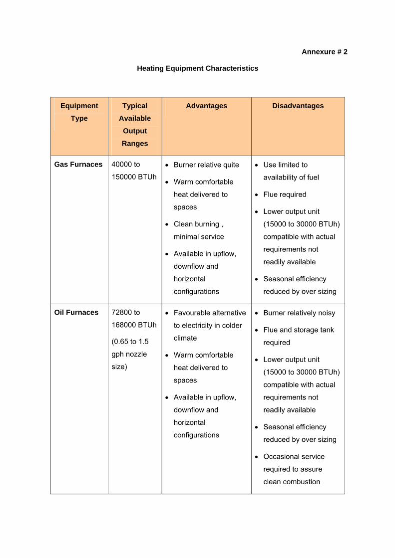
Annexure # 2
Heating Equipment Characteristics
Equipment Type
Typical Available
Output Ranges
Advantages Disadvantages
Gas Furnaces 40000 to
150000 BTUh • Burner relative quite
• Warm comfortable
heat delivered to
spaces
• Clean burning ,
minimal service
• Available in upflow,
downflow and
horizontal
configurations
• Use limited to
availability of fuel
• Flue required
• Lower output unit
(15000 to 30000 BTUh)
compatible with actual
requirements not
readily available
• Seasonal efficiency
reduced by over sizing
Oil Furnaces 72800 to
168000 BTUh
(0.65 to 1.5
gph nozzle
size)
• Favourable alternative
to electricity in colder
climate
• Warm comfortable
heat delivered to
spaces
• Available in upflow,
downflow and
horizontal
configurations
• Burner relatively noisy
• Flue and storage tank
required
• Lower output unit
(15000 to 30000 BTUh)
compatible with actual
requirements not
readily available
• Seasonal efficiency
reduced by over sizing
• Occasional service
required to assure
clean combustion
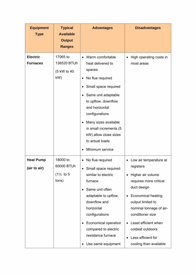
Equipment Type
Typical Available
Output Ranges
Advantages Disadvantages
Electric Furnaces
17065 to
136520 BTUh
(5 kW to 40
kW)
• Warm comfortable
heat delivered to
spaces
• No flue required
• Small space required
• Same unit adaptable
to upflow, downflow
and horizontal
configurations
• Many sizes available
in small increments (5
kW) allow close sizes
to actual loads
• Minimum service
• High operating costs in
most areas
Heat Pump
(air to air)
18000 to
60000 BTUh
(1½ to 5
tons)
• No flue required
• Small space required
similar to electric
furnace
• Same unit often
adaptable to upflow,
downflow and
horizontal
configurations
• Economical operation
compared to electric
resistance furnace
• Use same equipment
• Low air temperature at
registers
• Higher air volume
requires more critical
duct design
• Economical heating
output limited to
nominal tonnage of air-
conditioner size
• Least efficient when
coldest outdoors
• Less efficient for
cooling than available
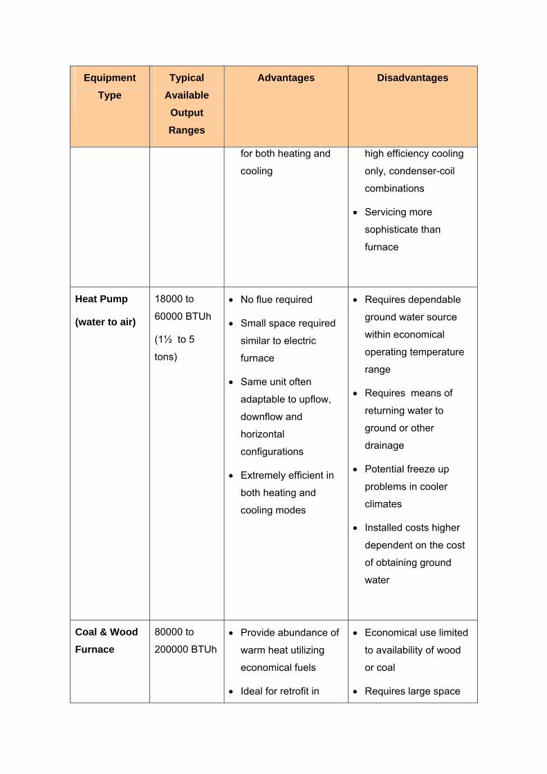
Equipment Type
Typical Available
Output Ranges
Advantages Disadvantages
for both heating and
cooling
high efficiency cooling
only, condenser-coil
combinations
• Servicing more
sophisticate than
furnace
Heat Pump
(water to air)
18000 to
60000 BTUh
(1½ to 5
tons)
• No flue required
• Small space required
similar to electric
furnace
• Same unit often
adaptable to upflow,
downflow and
horizontal
configurations
• Extremely efficient in
both heating and
cooling modes
• Requires dependable
ground water source
within economical
operating temperature
range
• Requires means of
returning water to
ground or other
drainage
• Potential freeze up
problems in cooler
climates
• Installed costs higher
dependent on the cost
of obtaining ground
water
Coal & Wood Furnace
80000 to
200000 BTUh
• Provide abundance of
warm heat utilizing
economical fuels
• Ideal for retrofit in
• Economical use limited
to availability of wood
or coal
• Requires large space

Equipment Type
Typical Available
Output Ranges
Advantages Disadvantages
poorly insulated older
homes
• Coal furnace can burn
coal, wood and even
trash
• Operation not
dependent on electric
supply, hence not
affected by outages
for coal, wood storage
and larger furnace
• Requires frequent daily
firing, coal handling and
ash removal is messy
and inconvenient
• Difficult to accurately
control temperature
• Tends to overheat
space during moderate
weather
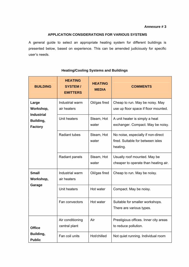
Annexure # 3
APPLICATION CONSIDERATIONS FOR VARIOUS SYSTEMS
A general guide to select an appropriate heating system for different buildings is
presented below, based on experience. This can be amended judiciously for specific
user’s needs.
Heating/Cooling Systems and Buildings
BUILDING HEATING SYSTEM / EMITTERS
HEATING MEDIA
COMMENTS
Industrial warm
air heaters
Oil/gas fired Cheap to run. May be noisy. May
use up floor space if floor mounted.
Unit heaters Steam, Hot
water
A unit heater is simply a heat
exchanger. Compact. May be noisy.
Radiant tubes Steam, Hot
water
No noise, especially if non-direct
fired. Suitable for between isles
heating.
Large Workshop, Industrial Building, Factory
Radiant panels Steam, Hot
water
Usually roof mounted. May be
cheaper to operate than heating air.
Industrial warm
air heaters
Oil/gas fired Cheap to run. May be noisy.
Unit heaters Hot water Compact. May be noisy.
Small Workshop, Garage
Fan convectors
Hot water Suitable for smaller workshops.
There are various types.
Air conditioning
central plant
Air Prestigious offices. Inner city areas
to reduce pollution.
Office Building, Public
Fan coil units Hot/chilled Not quiet running. Individual room

BUILDING HEATING SYSTEM / EMITTERS
HEATING MEDIA
COMMENTS
water control.
Room air
conditioners/
cassette units
Hot/chilled
water
Individual room control. May be
ceiling mounted.
Plenum heating Air Used in low heat gain areas.
Cheaper than air conditioning.
Radiators Hot water Require wall space. Easy to control.
Natural
convectors
Hot water Require wall space. Quite bulky.
Fan convectors Hot water May be noisy.
Underfloor
heating
Hot water No floor space required. Heat output
may not be sufficient
Building
Storage heaters Electric Easy to charge occupier. Can be
expensive to run.
Air conditioning
central plant
Air Calculate fresh air requirement. Air
distribution is important.
Large Public Hall, Auditoria
Plenum heating Air Cheaper than air conditioning.
Radiators Hot water High output usually required for
large buildings.
Underfloor
heating
Hot water If no wall space is available.
Church, Library
Quartz lamp
heaters
Electric
quartz tube
Electric heating may be economical
for occasional use.

BUILDING HEATING SYSTEM / EMITTERS
HEATING MEDIA
COMMENTS
High temperature
panels
Electric
metal plate
Small heat emitters. Can be roof
mounted.
Low temperature
panels
Electric
elements in
plate
Can be roof mounted.
Skirting heating Electric
element
Low output. May be used with other
systems.
Tubular heaters Electric
element
Mounted at low level.
Pipe coils Hot water Heaters under pews.
Air conditioning
central plant
Air Large Prestigious store. Use in
areas of high heat gain.
Room air
conditioners/
cassette units
Hot/chilled
water
Good control possibility. Compact.
Plenum heating Air Used if heat gains are minimal.
Radiators Hot water Use in small store.
Department Store, Supermarket
Fan convectors Hot water Use in small store. May be noisy.
Radiators Hot water Can be easily controlled with
thermostatic valves.
School, College, University
Radiators LST
(Low Surface
Temperature)
Warm water In Nursery schools limit water
temperature for safety.
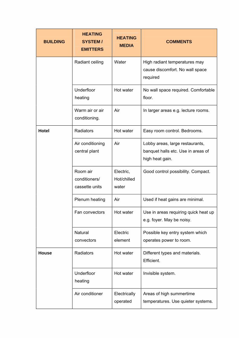
BUILDING HEATING SYSTEM / EMITTERS
HEATING MEDIA
COMMENTS
Radiant ceiling Water High radiant temperatures may
cause discomfort. No wall space
required
Underfloor
heating
Hot water No wall space required. Comfortable
floor.
Warm air or air
conditioning.
Air In larger areas e.g. lecture rooms.
Radiators Hot water Easy room control. Bedrooms.
Air conditioning
central plant
Air Lobby areas, large restaurants,
banquet halls etc. Use in areas of
high heat gain.
Room air
conditioners/
cassette units
Electric,
Hot/chilled
water
Good control possibility. Compact.
Plenum heating Air Used if heat gains are minimal.
Fan convectors Hot water Use in areas requiring quick heat up
e.g. foyer. May be noisy.
Hotel
Natural
convectors
Electric
element
Possible key entry system which
operates power to room.
Radiators Hot water Different types and materials.
Efficient.
Underfloor
heating
Hot water Invisible system.
House
Air conditioner Electrically
operated
Areas of high summertime
temperatures. Use quieter systems.
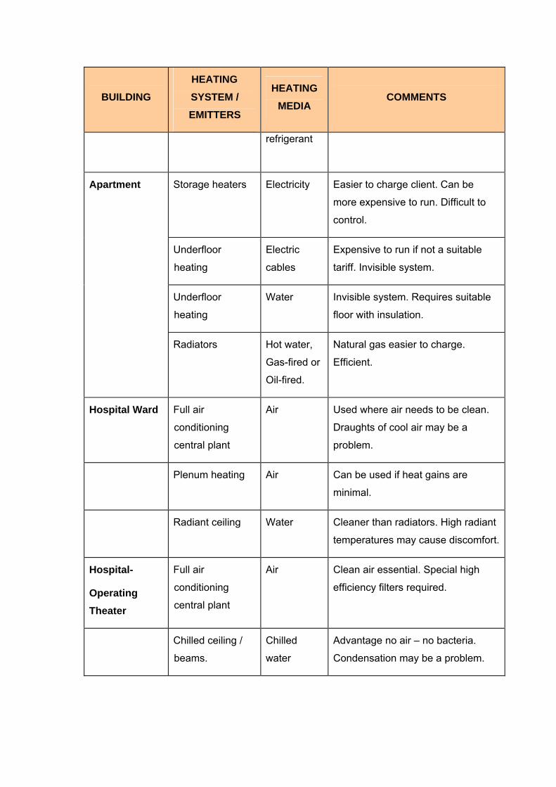
BUILDING HEATING SYSTEM / EMITTERS
HEATING MEDIA
COMMENTS
refrigerant
Storage heaters Electricity Easier to charge client. Can be
more expensive to run. Difficult to
control.
Underfloor
heating
Electric
cables
Expensive to run if not a suitable
tariff. Invisible system.
Underfloor
heating
Water Invisible system. Requires suitable
floor with insulation.
Apartment
Radiators Hot water,
Gas-fired or
Oil-fired.
Natural gas easier to charge.
Efficient.
Hospital Ward Full air
conditioning
central plant
Air Used where air needs to be clean.
Draughts of cool air may be a
problem.
Plenum heating Air Can be used if heat gains are
minimal.
Radiant ceiling Water Cleaner than radiators. High radiant
temperatures may cause discomfort.
Hospital-
Operating Theater
Full air
conditioning
central plant
Air Clean air essential. Special high
efficiency filters required.
Chilled ceiling /
beams.
Chilled
water
Advantage no air – no bacteria.
Condensation may be a problem.

Annexure # 4
ENERGY CONSERVATION & LOAD REDUCTION STRATEGIES
Heating requirements can be reduced through passive solar design and attention to
tightening the building envelope. The following tips may be useful for energy
conservation:
General Tips on Energy Conservation
1. Use a correctly sized heater for the space you are heating.
2. Heat only those areas in use at any one time.
3. The temperature of a heated room in the winter should be between 64-68°F.
4. Don't overheat. Every one-degree increase in temperature is a 10% increase in
heating bills and emissions.
5. Minimize heat loss through poor insulation by repairing faulty door seals, hanging
curtains that sit close to the window frames and laying rugs on bare floors.
6. Frequent changes in thermostat settings will increase operating costs.
7. Always light gas heaters in accordance with manufacturer instructions, turning
the setting down to a comfortable level after the burners are lit.
8. Keep all doors closed so that the warm air is restricted to the area requiring
heating.
9. Ensure ceiling space above all heated areas is adequately insulated.
10. Install draught seals and weather stripping around doors and windows. Air leaks
can account for 15-25% of heat loss from an uninsulated space and create
uncomfortable draughts.
11. Protect your windows - up to 40% of total heat loss from a space occurs through
uncovered windows. Close-fitting, heavy drapes or blinds, or double-glazed
windows reduce heat loss.
12. Zone your space: being able to close off different areas of your space allows you
to heat only those areas in use at any one time.
13. Open up curtains to north-facing windows on sunny winter days to let in the
natural warmth.
14. Wear warmer clothing - it's free, easy and will let you turn down your heater just a
few degrees more.
15. A wall-mounted heater is the safest to use in the bathroom. It should be mounted
at least 1.4 meters above the floor, well away from water taps and shower
outlets.
16. Don't leave the heater running on low overnight or while you are out.
17. Use a programmable thermostat. This simple, inexpensive device may provide
better savings than any other efficiency measure.
18. Turn off pilot lights (if fitted) over summer.
19. Maintain your heating system according to the manufacturer's instructions.
20. On dark winter days, cover windows with close fitting, floor length heavy curtains.
Up to 30% of total heat loss from a home occurs through uncovered windows.
Leaving curtains open can increase your heating bill by up to $80 per quarter for
the average home.
21. On sunny winter days, open up the curtains to north-facing windows for free
natural solar energy to warm your home.
22. Lower your thermostat setting at night and when there will be no one home for at
least 4 hours; a 10° setback can give you significant savings. Setback
thermostats save energy by automatically turning the thermostat down and up on
a preset schedule.
23. Registers - Look for and correct the following conditions:
• closed supply dampers
• drapes, furniture or carpet obstructing the supply and/or return registers or
grilles
• leaks in warm air ducts and cold air returns
• dust plugging the supply and/or return registers or grilles
• high pile carpet blocking baseboard radiators at the bottom
Load Reduction Strategies
1. Weatherize your home: Insulation and air-sealing improvements to the shell of
your building will always improve your comfort, regardless of the size and type of
heating system installed. Weatherization may also allow the installation of a
smaller, more economical heating system.
2. Doors and windows: Doors and windows should fit well and/or be draught-
proofed. Keep doors and windows closed when the heating is on, but don't block
ventilators or airbricks.
3. Curtains: Heavy curtains and/or thermal linings also help prevent heat loss.
Open windows on the sunny side when the sun is up so that the sun can warm
the rooms. Close all curtains when it gets dark. Do not have furniture close to or
in front of radiators. If you have deep windowsills, curtains should sit neatly on
top of them and not cover the radiator.
4. Filling in gaps between skirting boards and floor: Fill in any gaps between
skirting boards and the floor. This can be done with wood molding or with one of
the fillers.
5. Heat reflective foil behind radiators: Fit heat reflective foil behind radiators on
the outside walls to keep the heat inside your space, with the shiny side facing
into the room.
6. Draught proofing: Draughts are one of the main reasons why spaces feel cold
and cost a lot to heat. Draught strip windows, outside doors and the loft hatch,
and fill gaps in the ground floor floorboards and below the skirting board. Do not
cover vents/air bricks
7. Roof insulation: As much as 20% of your energy bill can be saved by effective
loft insulation. If you have a loft, it should have insulation at least 150 mm (6 in)
thick to keep the heat in. If your insulation is 50 mm (2 in) thick or less, you may
be eligible for a grant. Don't forget to insulate the loft hatch and pipes/tank in loft.
8. Cavity wall insulation: More heat is lost through the walls of an average
uninsulated building than by any other route. Most spaces built since the early
1930's have cavity walls (two walls with a gap in between) which can be filled
with insulating material. To install cavity wall insulation, most people will need to
employ a builder.
9. Solid wall insulation: Solid walls can be insulated but can be a problem to do. It
may be worth doing a north facing wall or one that is exposed.
10. Internal insulation: Timber battens can be fixed to the wall in order that
plasterboard, tongued and grooved boarding or a decorative wallboard can be
attached. The timber bates are in-filled with insulation such as mineral wool.
Make sure a vapor barrier is installed to reduce the risk of interstitial
condensation. Remember that internal solid wall insulation will reduce the room
size by approximately 50 mm (2 in) along the side of the wall. Light switches,
plugs and skirting boards will have to be removed and replaced. This measure is
very disruptive if occupants are living in the property at the time of the work.
11. External insulation: It is a job for a specialist contractor, and you can obtain
from the External Wall Insulation Association a list of their members and
descriptions of the systems they offer.
12. Floor insulation: As much as 10% can be lost through floorboards. If there is
easy access to the joists under the floorboards, you can insulate from below by
filling the spaces between the joists with mineral wool mat or expanded
polystyrene boards.
13. Double glazing: Large windows cause heat loss; double-glazing could be an
option. Even draught-proofed, single glazed windows allow a lot of heat to be lost
(around 20% of the total heat). Heat loss through windows can be halved with
double-glazing. Professionally fitted double-glazing can be expensive, but if you
need new windows, having double-glazing fitted is the sensible thing to do as it
makes rooms more comfortable. Put double-glazing in the rooms you use the
most and on large windows first. Where double-glazing can halve the heat loss
through windows, double-glazing with low emissivity glass can further reduce it
by 30%.
********************