Embed Size (px)
Citation preview
Course in ANSYS
Example0702
Computational Mechanics, AAU, EsbjergAutoDesk Inventor
Syllabus 2Computational Mechanics, AAU, EsbjergAutoDesk Inventor
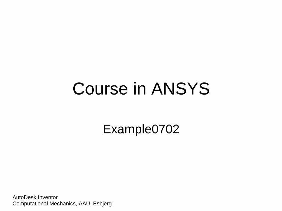
Example – Plate with a hole
E = 210000N/mm2
n = 0.3a = 200mmb = 100mmt = 10mmr = 10mms = 100N/mm2
Objective:Determine the maximum stress in the x-direction for point A and display the deformation figureTasks:Create a submodel to increase the accuracy of the FEA without increasing the computational effort significantly?Topics:Element type, Real constants, modeling, mapped mesh, plot results, output graphics, path operations, submodeling
A
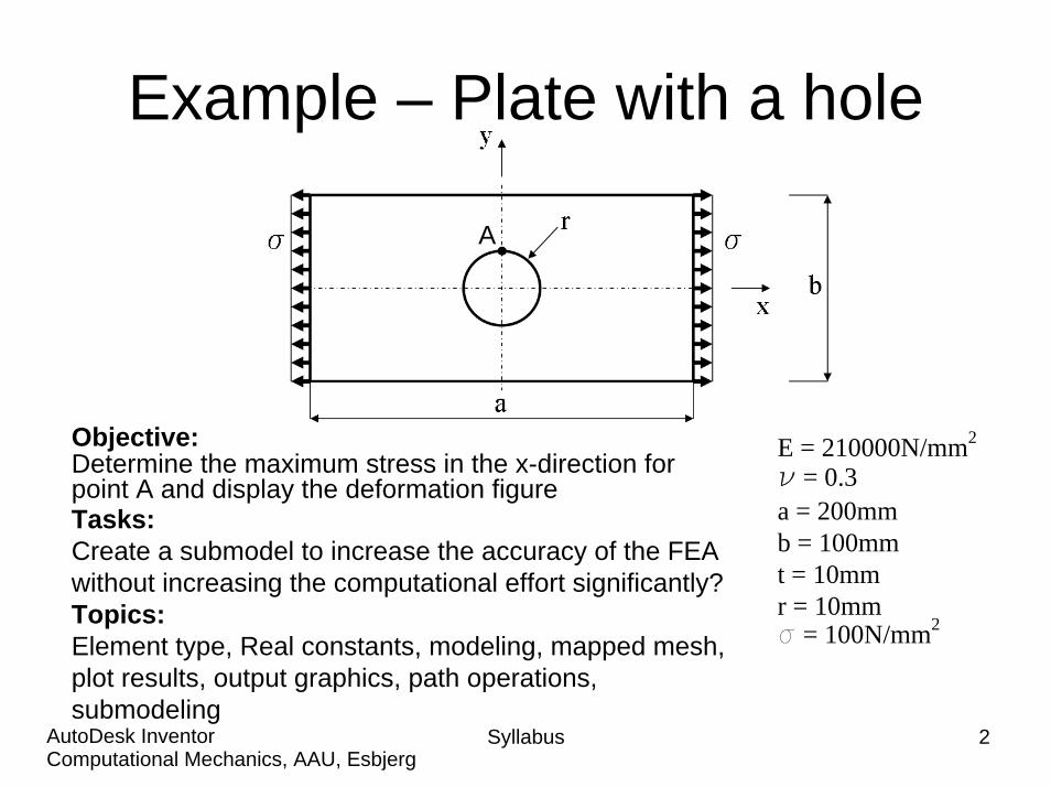
Steps in Submodeling
• The process for using submodeling is as follows: –– Create and analyze the coarse model.Create and analyze the coarse model.– Create the submodel.– Perform cut boundary interpolation (CBI).– Analyze the submodel.– Verify that the distance between the cut
boundaries and the stress concentration is adequate.
Syllabus 3Computational Mechanics, AAU, EsbjergAutoDesk Inventor
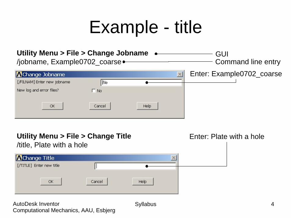
Example - titleUtility Menu > File > Change Jobname/jobname, Example0702_coarse Command line entry
GUI
Enter: Example0702_coarse
Utility Menu > File > Change Title/title, Plate with a hole
Enter: Plate with a hole
Syllabus 4Computational Mechanics, AAU, EsbjergAutoDesk Inventor
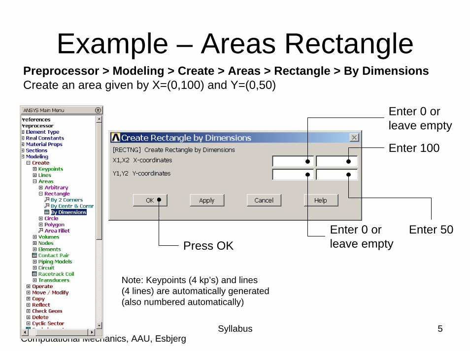
Example – Areas RectanglePreprocessor > Modeling > Create > Areas > Rectangle > By DimensionsCreate an area given by X=(0,100) and Y=(0,50)
Enter 0 orleave empty
Syllabus 5Computational Mechanics, AAU, EsbjergAutoDesk Inventor
Enter 100
Enter 50Enter 0 orleave emptyPress OK
Note: Keypoints (4 kp’s) and lines(4 lines) are automatically generated(also numbered automatically)
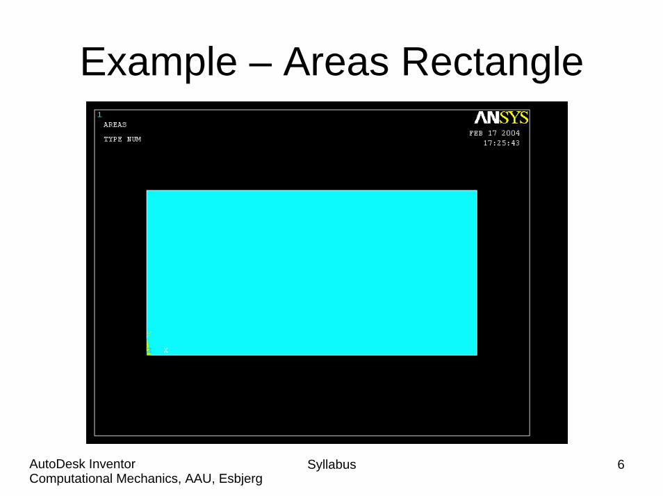
Example – Areas Rectangle
Syllabus 6Computational Mechanics, AAU, EsbjergAutoDesk Inventor
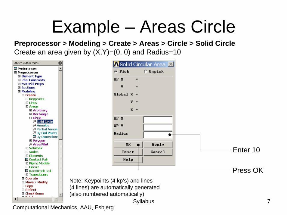
Example – Areas CirclePreprocessor > Modeling > Create > Areas > Circle > Solid CircleCreate an area given by (X,Y)=(0, 0) and Radius=10
Syllabus 7Computational Mechanics, AAU, EsbjergAutoDesk Inventor
Enter 10
Press OKNote: Keypoints (4 kp’s) and lines(4 lines) are automatically generated(also numbered automatically)
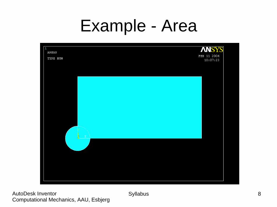
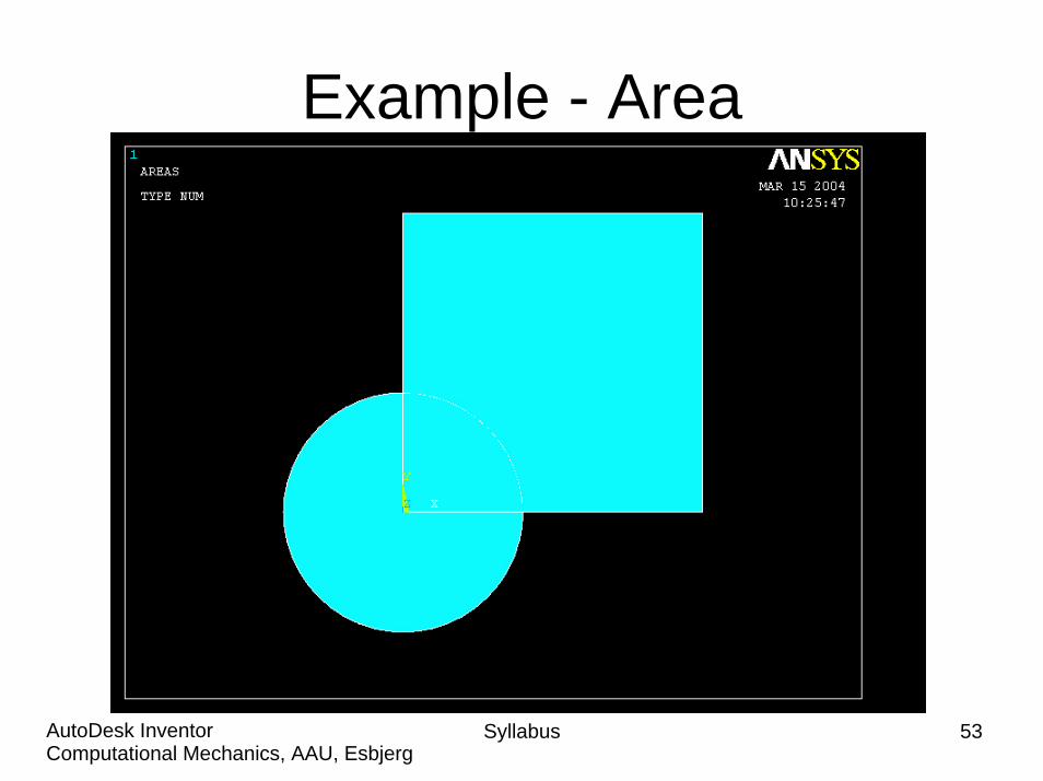
Example - Area
Syllabus 8Computational Mechanics, AAU, EsbjergAutoDesk Inventor
Syllabus 9Computational Mechanics, AAU, EsbjergAutoDesk Inventor
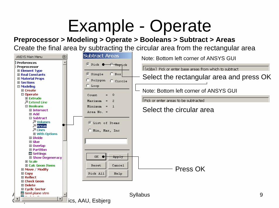
Example - OperatePreprocessor > Modeling > Operate > Booleans > Subtract > AreasCreate the final area by subtracting the circular area from the rectangular area
Note: Bottom left corner of ANSYS GUI
Press OK
Select the rectangular area and press OK
Note: Bottom left corner of ANSYS GUI
Select the circular area
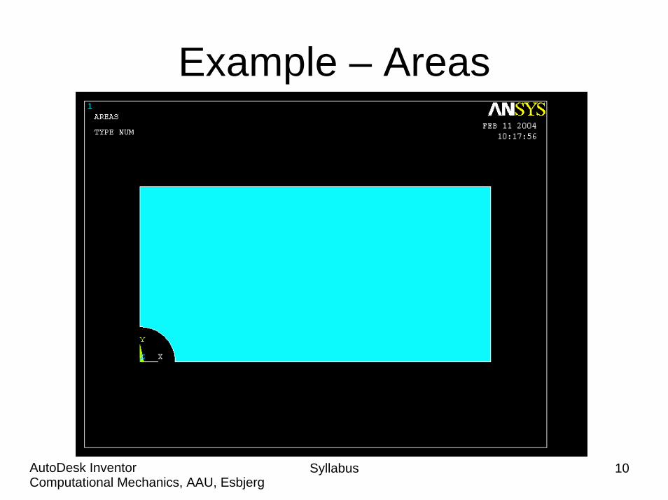
Example – Areas
Syllabus 10Computational Mechanics, AAU, EsbjergAutoDesk Inventor
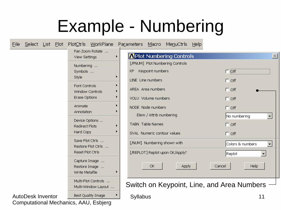
Example - Numbering
Syllabus 11Computational Mechanics, AAU, EsbjergAutoDesk Inventor
Switch on Keypoint, Line, and Area Numbers
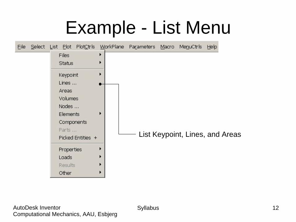
Example - List Menu
List Keypoint, Lines, and Areas
Syllabus 12Computational Mechanics, AAU, EsbjergAutoDesk Inventor
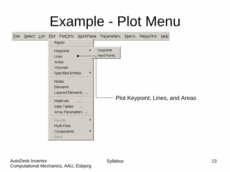
Example - Plot Menu
Plot Keypoint, Lines, and Areas
Syllabus 13Computational Mechanics, AAU, EsbjergAutoDesk Inventor
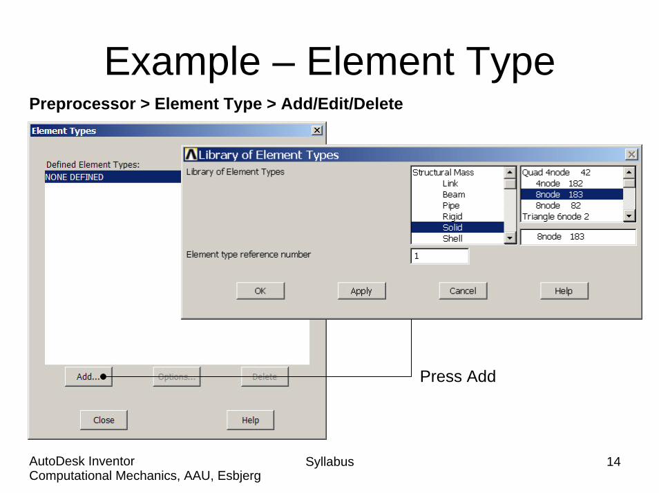
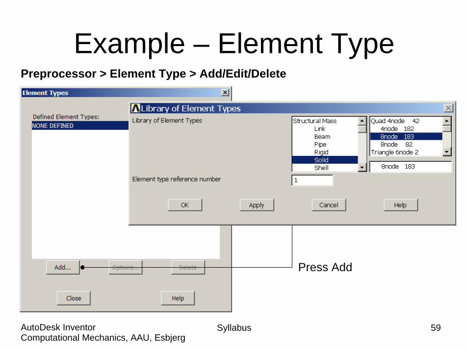
Example – Element TypePreprocessor > Element Type > Add/Edit/Delete
Press Add
Syllabus 14Computational Mechanics, AAU, EsbjergAutoDesk Inventor
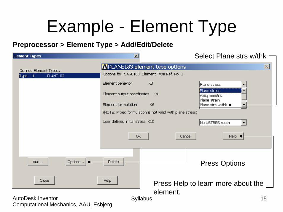
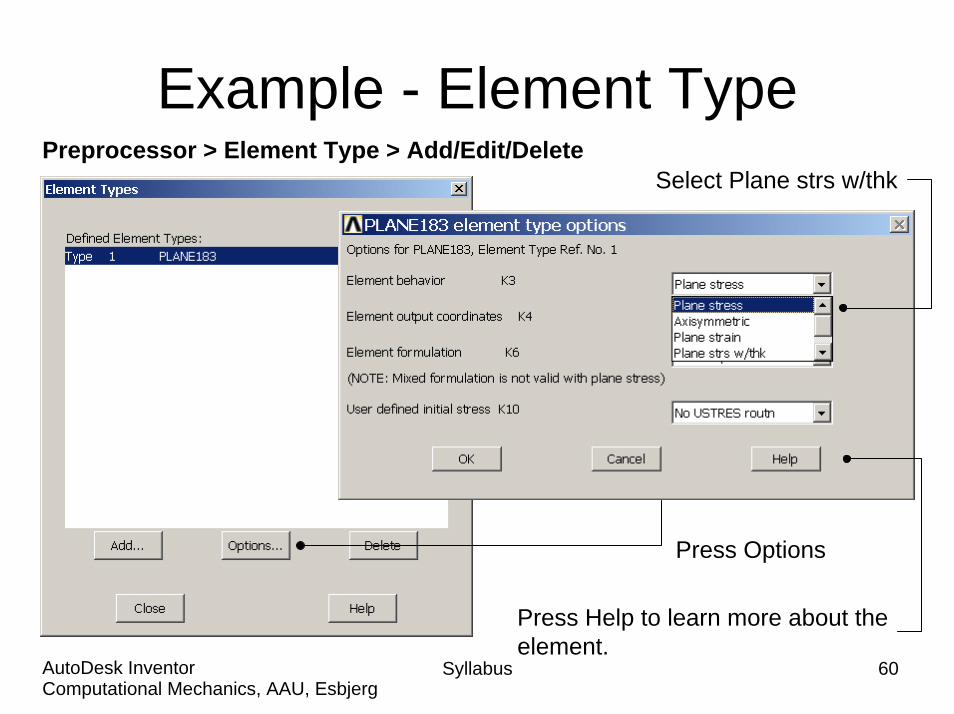
Example - Element TypePreprocessor > Element Type > Add/Edit/Delete
Syllabus 15Computational Mechanics, AAU, EsbjergAutoDesk Inventor
Press Options
Press Help to learn more about theelement.
Select Plane strs w/thk

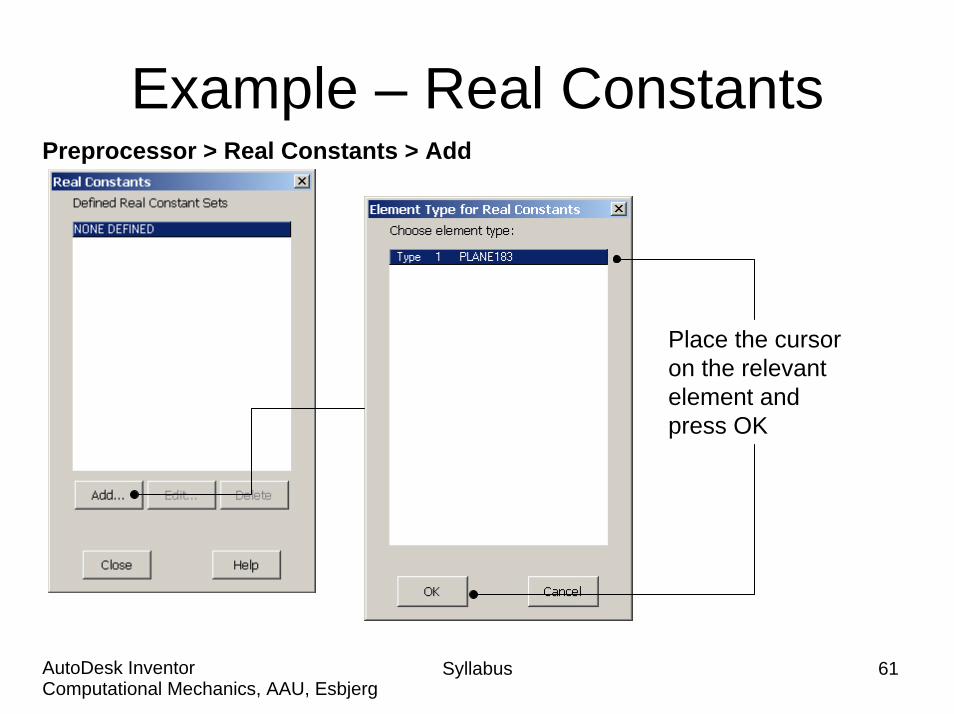
Example – Real ConstantsPreprocessor > Real Constants > Add
Place the cursoron the relevantelement andpress OK
Syllabus 16Computational Mechanics, AAU, EsbjergAutoDesk Inventor
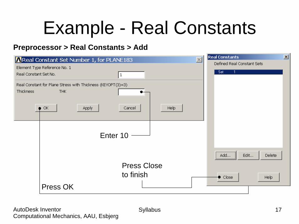
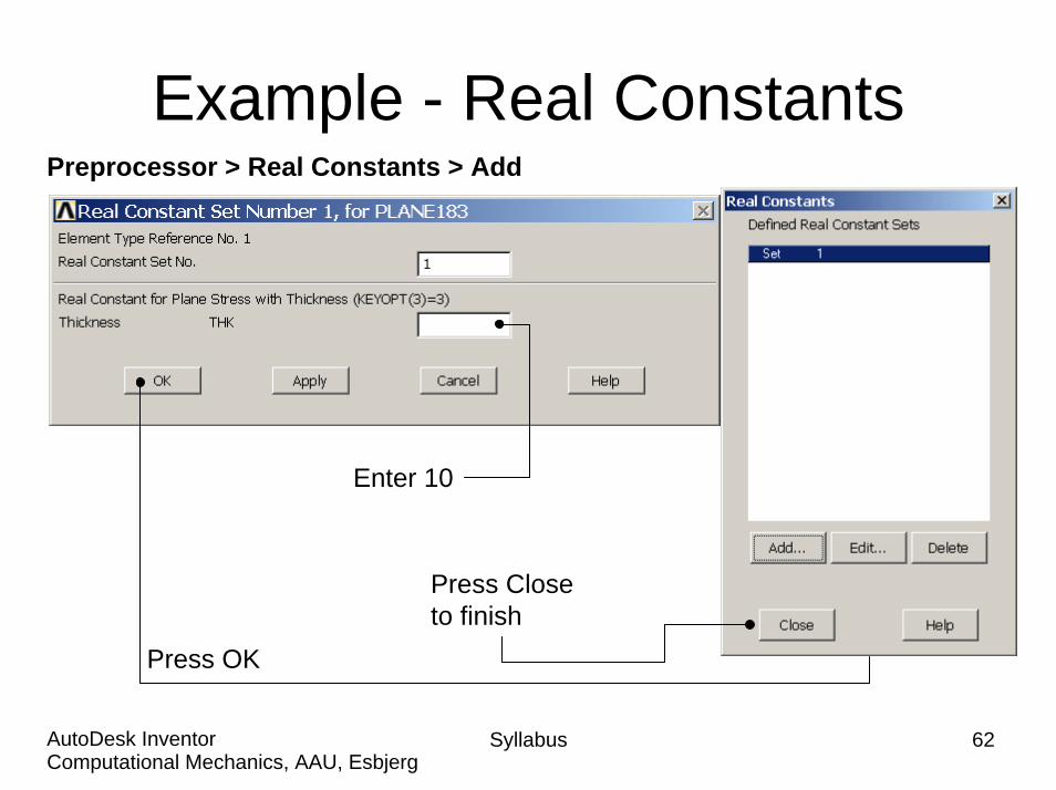
Example - Real ConstantsPreprocessor > Real Constants > Add
Press OK
Press Closeto finish
Enter 10
Syllabus 17Computational Mechanics, AAU, EsbjergAutoDesk Inventor

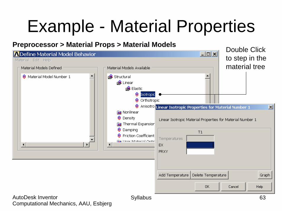
Example - Material PropertiesPreprocessor > Material Props > Material Models
Double Clickto step in thematerial tree
Syllabus 18Computational Mechanics, AAU, EsbjergAutoDesk Inventor
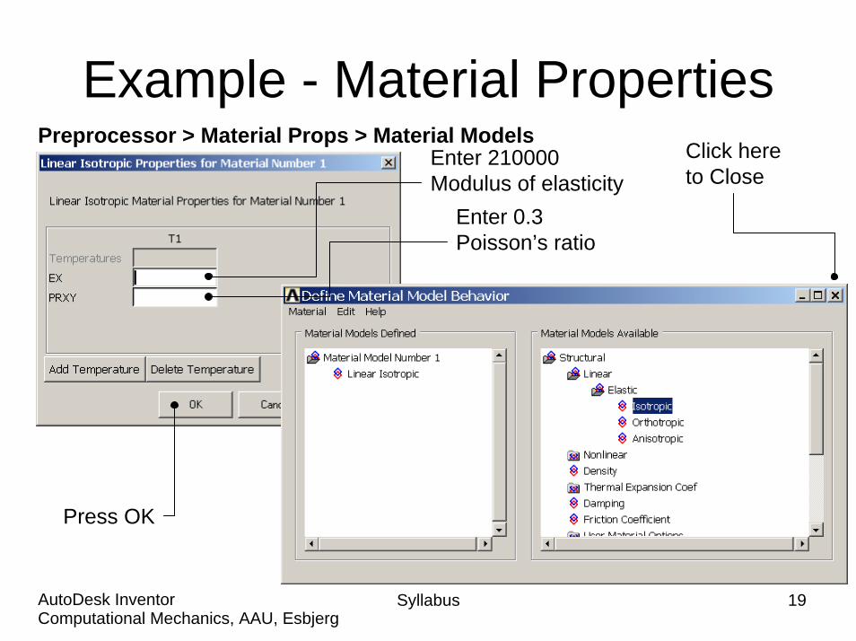
Example - Material Properties
Syllabus 19Computational Mechanics, AAU, EsbjergAutoDesk Inventor
Preprocessor > Material Props > Material ModelsEnter 210000Modulus of elasticity
Enter 0.3Poisson’s ratio
Click hereto Close
Press OK
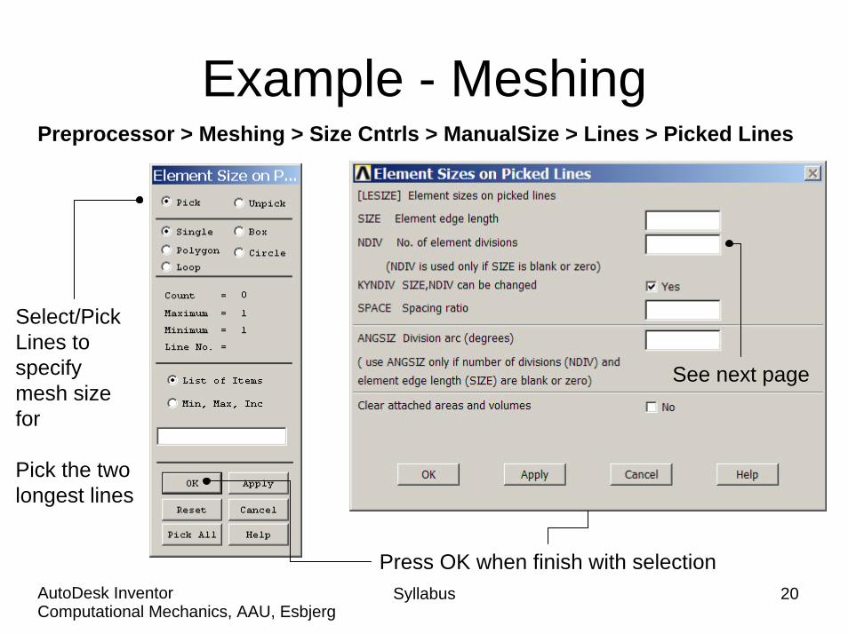
Example - MeshingPreprocessor > Meshing > Size Cntrls > ManualSize > Lines > Picked Lines
Syllabus 20Computational Mechanics, AAU, EsbjergAutoDesk Inventor
Select/PickLines tospecifymesh sizefor
Pick the twolongest lines
Press OK when finish with selection
See next page

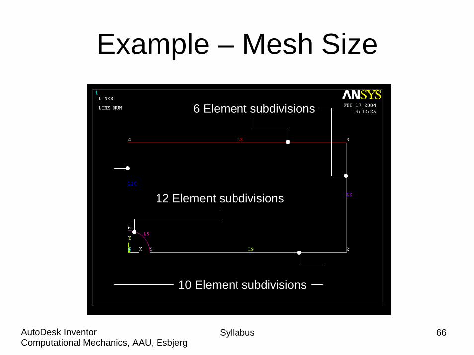
Example – Mesh Size
3 Element subdivisions
5 Element subdivisions
6 Element subdivisions
Syllabus 21Computational Mechanics, AAU, EsbjergAutoDesk Inventor
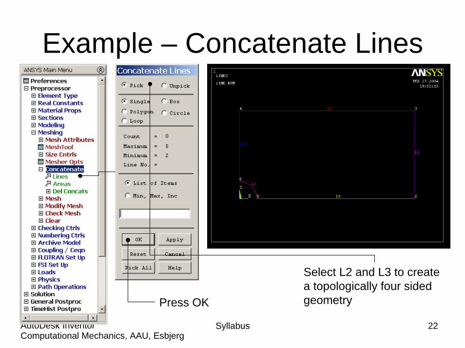
Example – Concatenate Lines
Syllabus 22Computational Mechanics, AAU, EsbjergAutoDesk Inventor
Select L2 and L3 to create a topologically four sided geometryPress OK
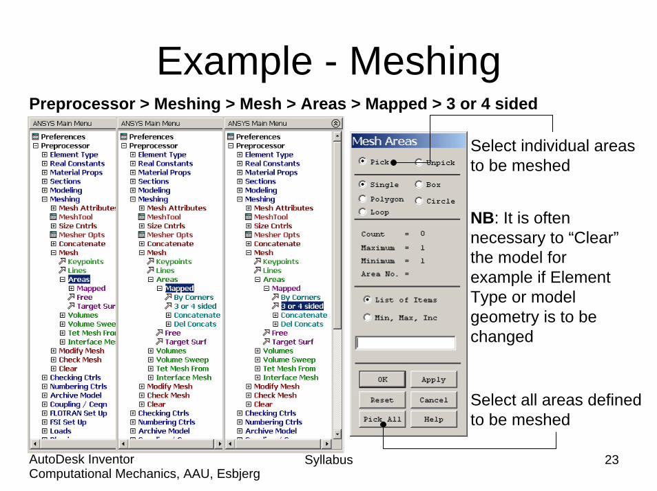
Example - MeshingPreprocessor > Meshing > Mesh > Areas > Mapped > 3 or 4 sided
Syllabus 23Computational Mechanics, AAU, EsbjergAutoDesk Inventor
Select individual areasto be meshed
Select all areas definedto be meshed
NB: It is often necessary to “Clear” the model forexample if Element Type or model geometry is to be changed
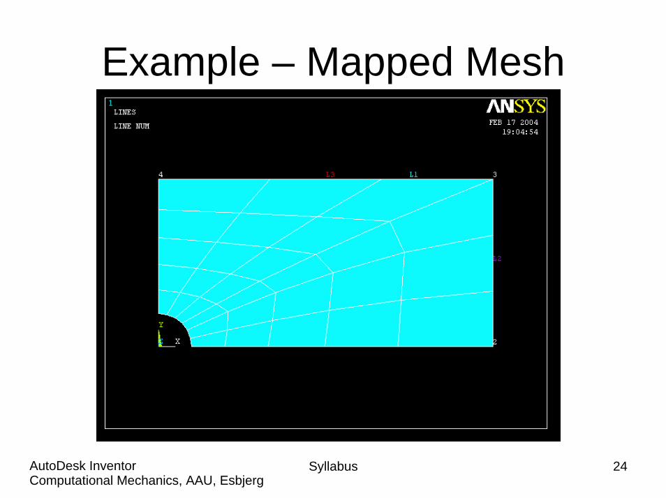
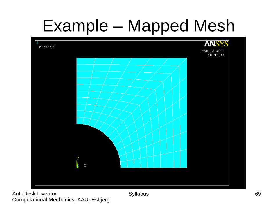
Example – Mapped Mesh
Syllabus 24Computational Mechanics, AAU, EsbjergAutoDesk Inventor
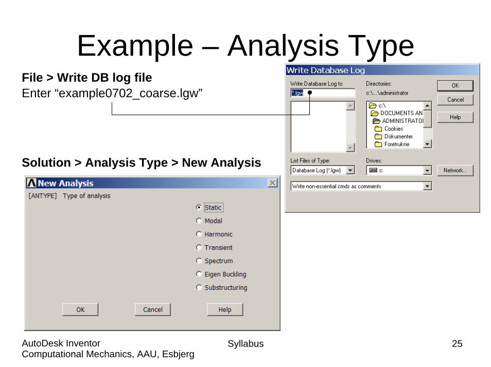
Example – Analysis Type
Solution > Analysis Type > New Analysis
File > Write DB log fileEnter “example0702_coarse.lgw”
Syllabus 25Computational Mechanics, AAU, EsbjergAutoDesk Inventor

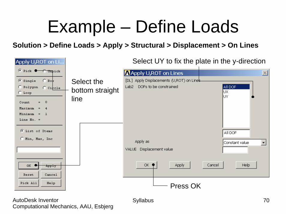
Example – Define LoadsSolution > Define Loads > Apply > Structural > Displacement > On Lines
Select UY to fix the plate in the y-direction
Select the bottom straight line
Press OK
Syllabus 26Computational Mechanics, AAU, EsbjergAutoDesk Inventor

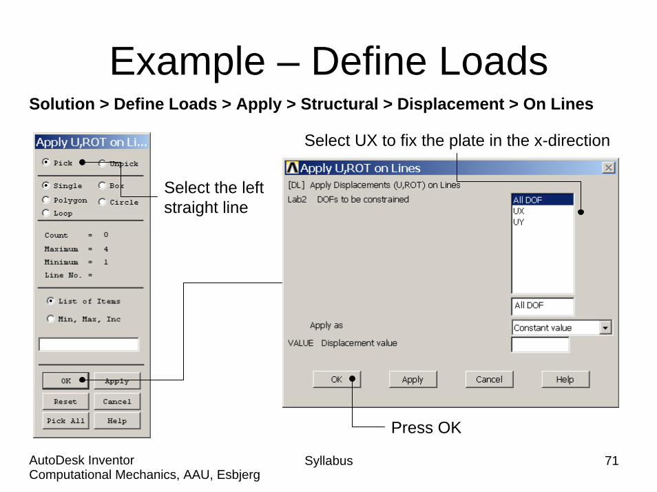
Example – Define LoadsSolution > Define Loads > Apply > Structural > Displacement > On Lines
Select UX to fix the plate in the x-direction
Select the left straight line
Press OK
Syllabus 27Computational Mechanics, AAU, EsbjergAutoDesk Inventor
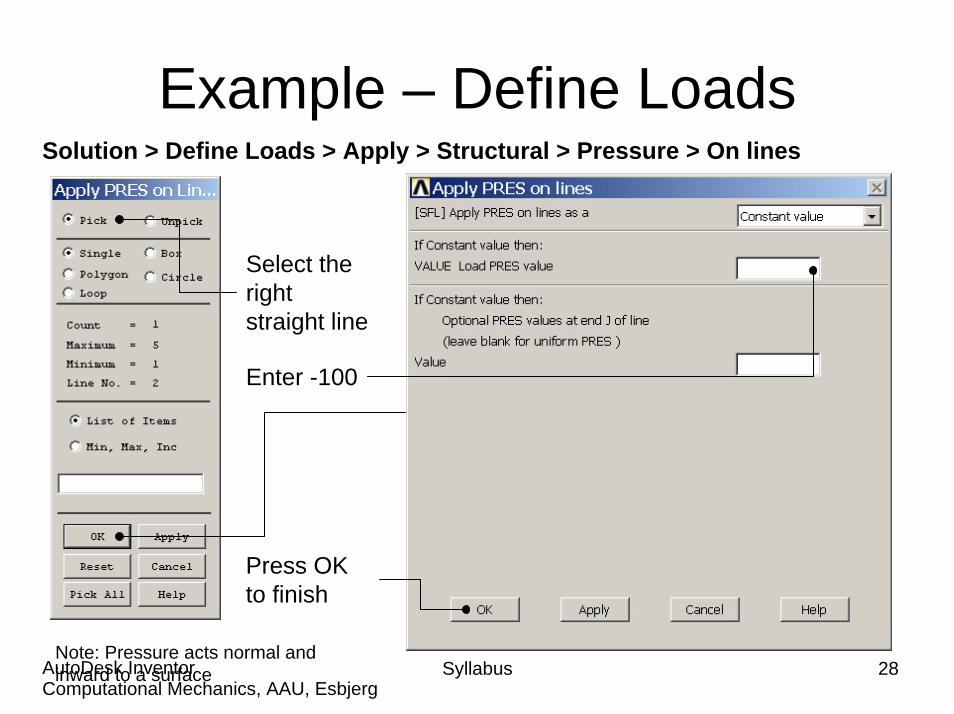
Example – Define LoadsSolution > Define Loads > Apply > Structural > Pressure > On lines
Select the right straight line
Enter -100
Press OK to finish
Syllabus 28Computational Mechanics, AAU, EsbjergAutoDesk Inventor
Note: Pressure acts normal and inward to a surface
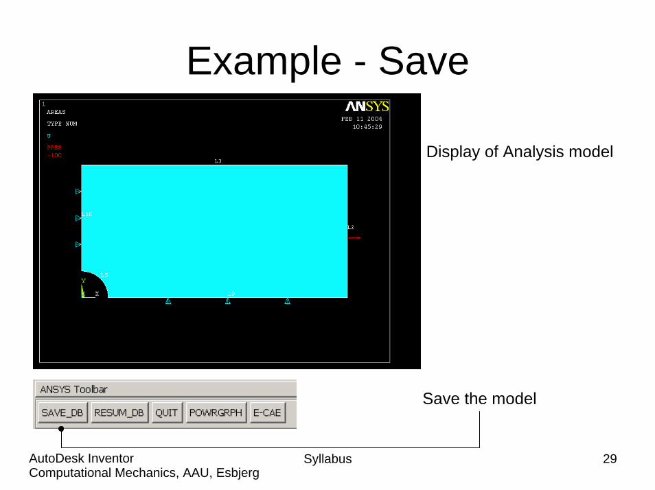
Example - Save
Display of Analysis model
Save the model
Syllabus 29Computational Mechanics, AAU, EsbjergAutoDesk Inventor
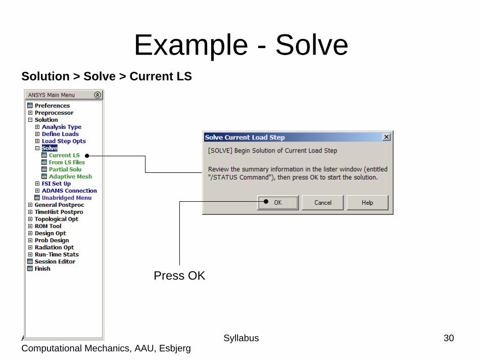
Example - SolveSolution > Solve > Current LS
Syllabus 30Computational Mechanics, AAU, EsbjergAutoDesk Inventor
Press OK

Example - SolvePress Close
Press hereto Close
Syllabus 31Computational Mechanics, AAU, EsbjergAutoDesk Inventor

Example – Contour PlotGeneral Postproc > Plot Results > Contour Plot > Nodal Sol
Select Stress
Select SX for stresses in x-direction
Syllabus 32Computational Mechanics, AAU, EsbjergAutoDesk Inventor
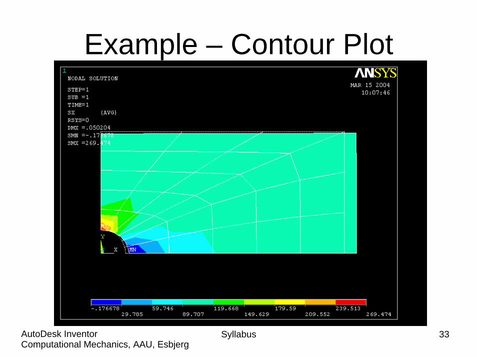
Example – Contour Plot
Syllabus 33Computational Mechanics, AAU, EsbjergAutoDesk Inventor
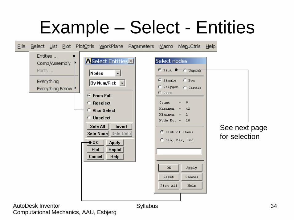
Example – Select - Entities
See next page for selection
Syllabus 34Computational Mechanics, AAU, EsbjergAutoDesk Inventor

Syllabus 35Computational Mechanics, AAU, EsbjergAutoDesk Inventor
Example – Select Nodes
Select the indicated nodes
Enter OK when finished
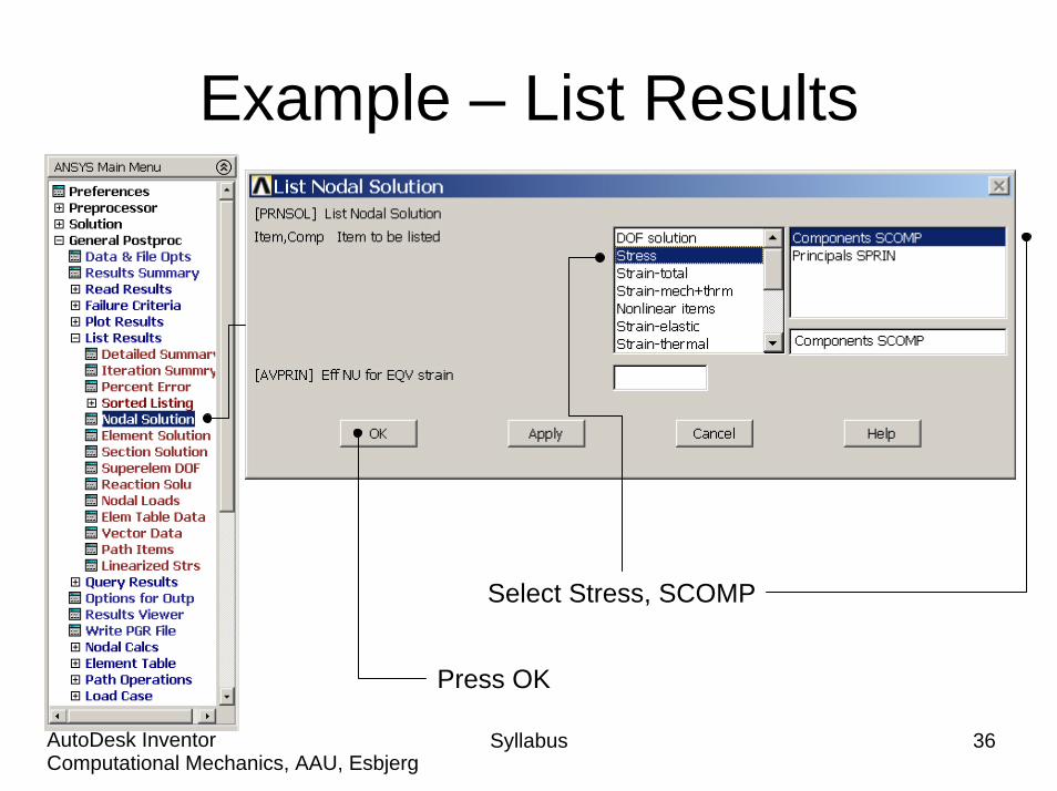
Example – List Results
Syllabus 36Computational Mechanics, AAU, EsbjergAutoDesk Inventor
Select Stress, SCOMP
Press OK
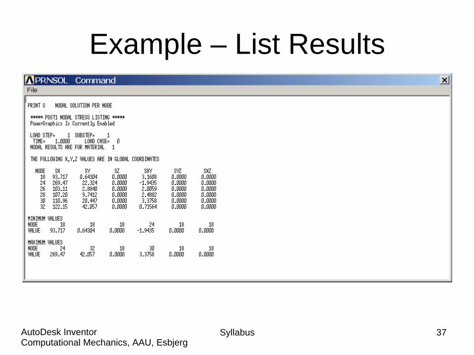
Example – List Results
Syllabus 37Computational Mechanics, AAU, EsbjergAutoDesk Inventor

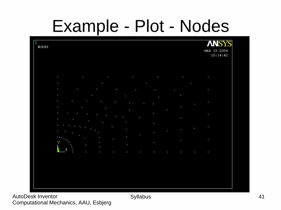
Example - Plot - Nodes
Plot Nodes
Only 11 FE nodes are displayed – the same nodes as selected previously
Syllabus 38Computational Mechanics, AAU, EsbjergAutoDesk Inventor
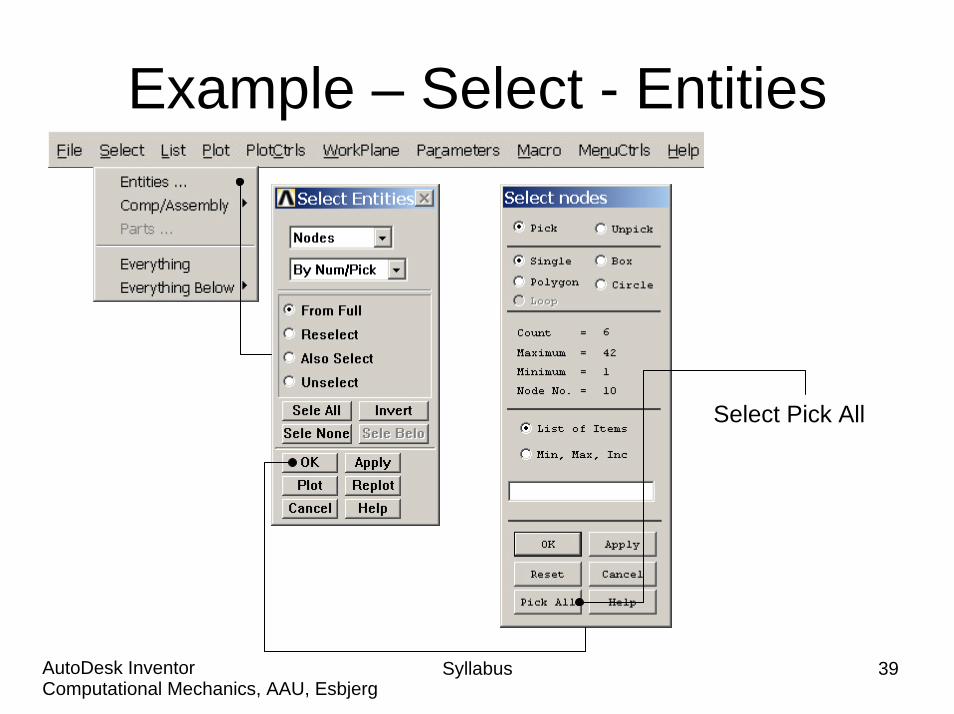
Example – Select - Entities
Select Pick All
Syllabus 39Computational Mechanics, AAU, EsbjergAutoDesk Inventor

Example - Plot - Nodes
Plot Nodes
Syllabus 40Computational Mechanics, AAU, EsbjergAutoDesk Inventor
Example - Plot - Nodes
Syllabus 41Computational Mechanics, AAU, EsbjergAutoDesk Inventor
Syllabus 42Computational Mechanics, AAU, EsbjergAutoDesk Inventor
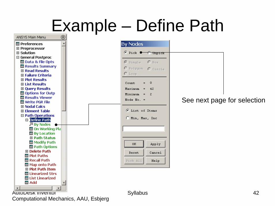
Example – Define Path
See next page for selection
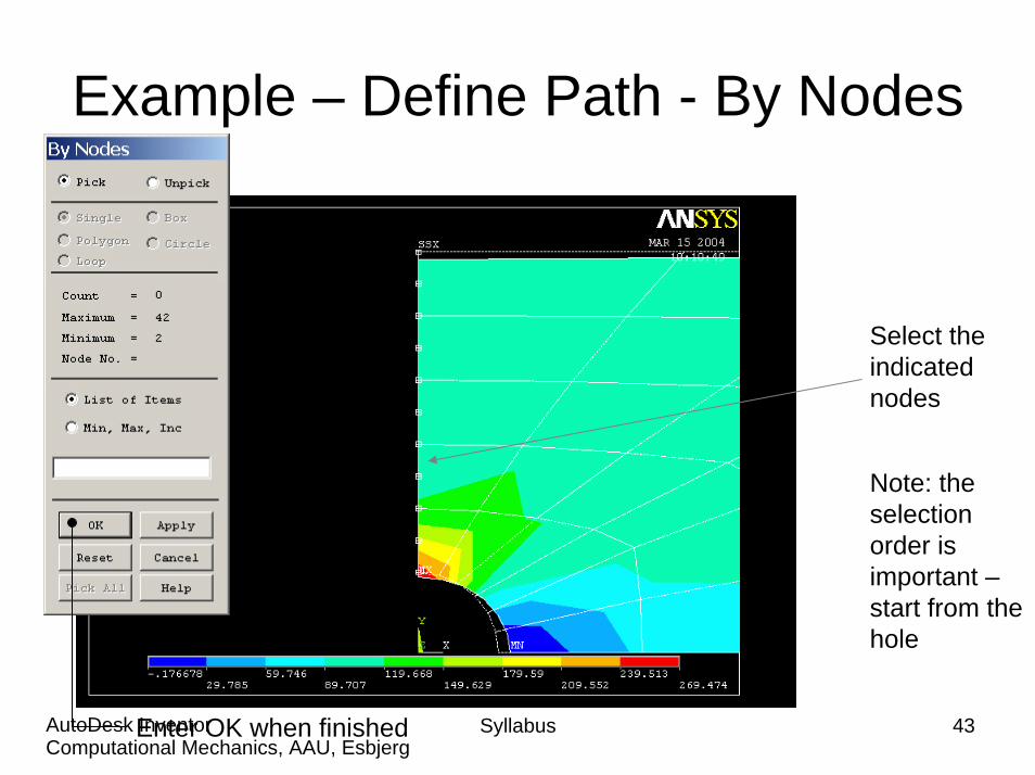
Example – Define Path - By Nodes
Syllabus 43Computational Mechanics, AAU, EsbjergAutoDesk InventorEnter OK when finished
Select the indicated nodes
Note: the selection order is important –start from the hole
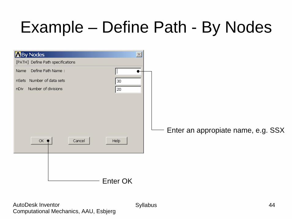
Example – Define Path - By Nodes
Enter an appropiate name, e.g. SSX
Enter OK
Syllabus 44Computational Mechanics, AAU, EsbjergAutoDesk Inventor

Syllabus 45Computational Mechanics, AAU, EsbjergAutoDesk Inventor
Example – Map onto Path
Select Stress, SX
Press OK

Syllabus 46Computational Mechanics, AAU, EsbjergAutoDesk Inventor
Example – Plot Path on Graph
Select SX
Press OK
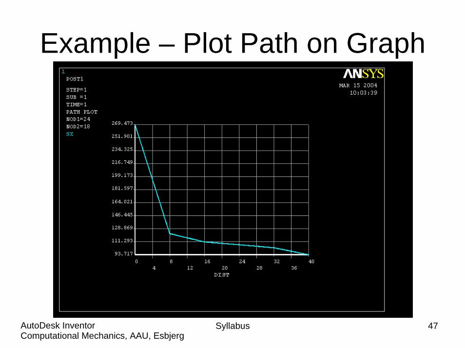
Example – Plot Path on Graph
Syllabus 47Computational Mechanics, AAU, EsbjergAutoDesk Inventor
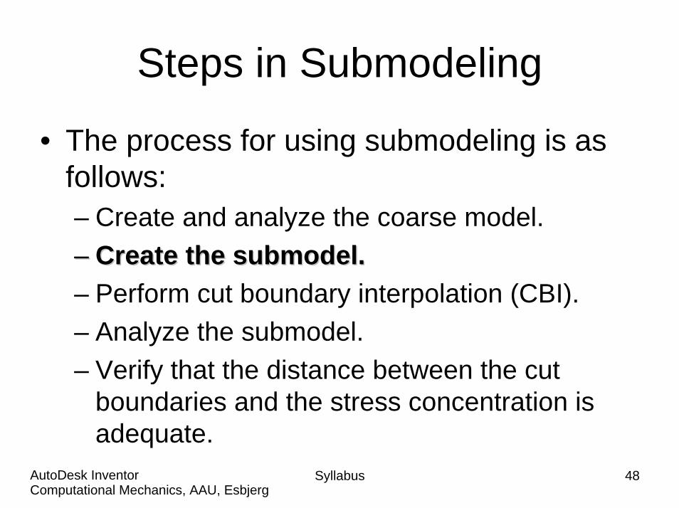
Steps in Submodeling
• The process for using submodeling is as follows: – Create and analyze the coarse model.–– Create the Create the submodelsubmodel..– Perform cut boundary interpolation (CBI).– Analyze the submodel.– Verify that the distance between the cut
boundaries and the stress concentration is adequate.
Syllabus 48Computational Mechanics, AAU, EsbjergAutoDesk Inventor
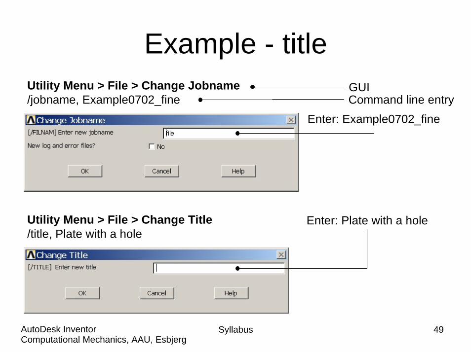
Example - titleUtility Menu > File > Change Jobname/jobname, Example0702_fine Command line entry
GUI
Enter: Example0702_fine
Utility Menu > File > Change Title/title, Plate with a hole
Enter: Plate with a hole
Syllabus 49Computational Mechanics, AAU, EsbjergAutoDesk Inventor
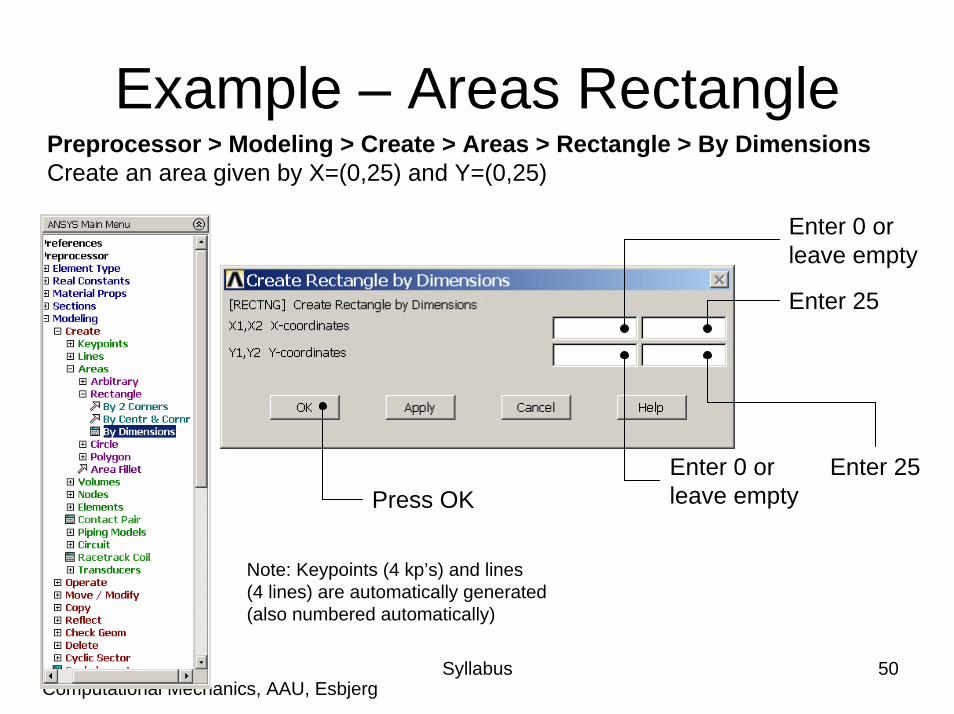
Example – Areas RectanglePreprocessor > Modeling > Create > Areas > Rectangle > By DimensionsCreate an area given by X=(0,25) and Y=(0,25)
Enter 0 orleave empty
Syllabus 50Computational Mechanics, AAU, EsbjergAutoDesk Inventor
Enter 25
Enter 25Enter 0 orleave emptyPress OK
Note: Keypoints (4 kp’s) and lines(4 lines) are automatically generated(also numbered automatically)
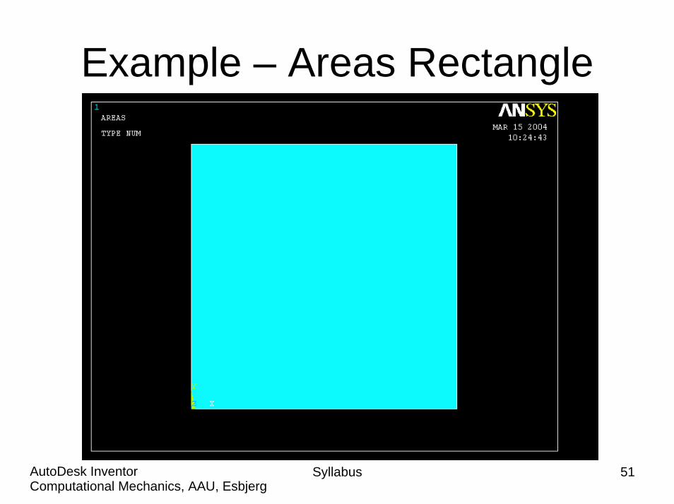
Example – Areas Rectangle
Syllabus 51Computational Mechanics, AAU, EsbjergAutoDesk Inventor

Example – Areas CirclePreprocessor > Modeling > Create > Areas > Circle > Solid CircleCreate an area given by (X,Y)=(0, 0) and Radius=10
Syllabus 52Computational Mechanics, AAU, EsbjergAutoDesk Inventor
Enter 10
Press OKNote: Keypoints (4 kp’s) and lines(4 lines) are automatically generated(also numbered automatically)
Example - Area
Syllabus 53Computational Mechanics, AAU, EsbjergAutoDesk Inventor

Syllabus 54Computational Mechanics, AAU, EsbjergAutoDesk Inventor
Example - OperatePreprocessor > Modeling > Operate > Booleans > Subtract > AreasCreate the final area by subtracting the circular area from the rectangular area
Note: Bottom left corner of ANSYS GUI
Press OK
Select the rectangular area and press OK
Note: Bottom left corner of ANSYS GUI
Select the circular area
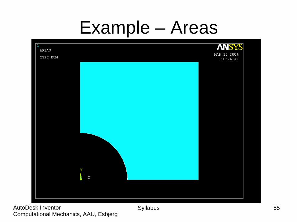
Example – Areas
Syllabus 55Computational Mechanics, AAU, EsbjergAutoDesk Inventor

Example - Numbering
Syllabus 56Computational Mechanics, AAU, EsbjergAutoDesk Inventor
Switch on Keypoint, Line, and Area Numbers

Example - List Menu
List Keypoint, Lines, and Areas
Syllabus 57Computational Mechanics, AAU, EsbjergAutoDesk Inventor

Example - Plot Menu
Plot Keypoint, Lines, and Areas
Syllabus 58Computational Mechanics, AAU, EsbjergAutoDesk Inventor
Example – Element TypePreprocessor > Element Type > Add/Edit/Delete
Press Add
Syllabus 59Computational Mechanics, AAU, EsbjergAutoDesk Inventor
Example - Element TypePreprocessor > Element Type > Add/Edit/Delete
Press Options
Syllabus 60Computational Mechanics, AAU, EsbjergAutoDesk Inventor
Press Help to learn more about theelement.
Select Plane strs w/thk
Example – Real ConstantsPreprocessor > Real Constants > Add
Place the cursoron the relevantelement andpress OK
Syllabus 61Computational Mechanics, AAU, EsbjergAutoDesk Inventor
Example - Real ConstantsPreprocessor > Real Constants > Add
Press OK
Press Closeto finish
Enter 10
Syllabus 62Computational Mechanics, AAU, EsbjergAutoDesk Inventor
Example - Material PropertiesPreprocessor > Material Props > Material Models
Double Clickto step in thematerial tree
Syllabus 63Computational Mechanics, AAU, EsbjergAutoDesk Inventor

Example - Material Properties
Syllabus 64Computational Mechanics, AAU, EsbjergAutoDesk Inventor
Preprocessor > Material Props > Material ModelsEnter 210000Modulus of elasticity
Enter 0.3Poisson’s ratio
Click hereto Close
Press OK

Example - MeshingPreprocessor > Meshing > Size Cntrls > ManualSize > Lines > Picked Lines
Syllabus 65Computational Mechanics, AAU, EsbjergAutoDesk Inventor
Select/PickLines tospecifymesh sizefor
Pick the twolongest lines
Press OK when finish with selection
See next page
Example – Mesh Size
6 Element subdivisions
10 Element subdivisions
12 Element subdivisions
Syllabus 66Computational Mechanics, AAU, EsbjergAutoDesk Inventor

Example – Concatenate Lines
Syllabus 67Computational Mechanics, AAU, EsbjergAutoDesk Inventor
Select L2 and L3 to create a topologically four sided geometryPress OK

Example - MeshingPreprocessor > Meshing > Mesh > Areas > Mapped > 3 or 4 sided
Syllabus 68Computational Mechanics, AAU, EsbjergAutoDesk Inventor
Select individual areasto be meshed
Select all areas definedto be meshed
NB: It is often necessary to “Clear” the model forexample if Element Type or model geometry is to be changed
Example – Mapped Mesh
Syllabus 69Computational Mechanics, AAU, EsbjergAutoDesk Inventor
Example – Define LoadsSolution > Define Loads > Apply > Structural > Displacement > On Lines
Select UY to fix the plate in the y-direction
Select the bottom straight line
Press OK
Syllabus 70Computational Mechanics, AAU, EsbjergAutoDesk Inventor
Example – Define LoadsSolution > Define Loads > Apply > Structural > Displacement > On Lines
Select UX to fix the plate in the x-direction
Select the left straight line
Press OK
Syllabus 71Computational Mechanics, AAU, EsbjergAutoDesk Inventor
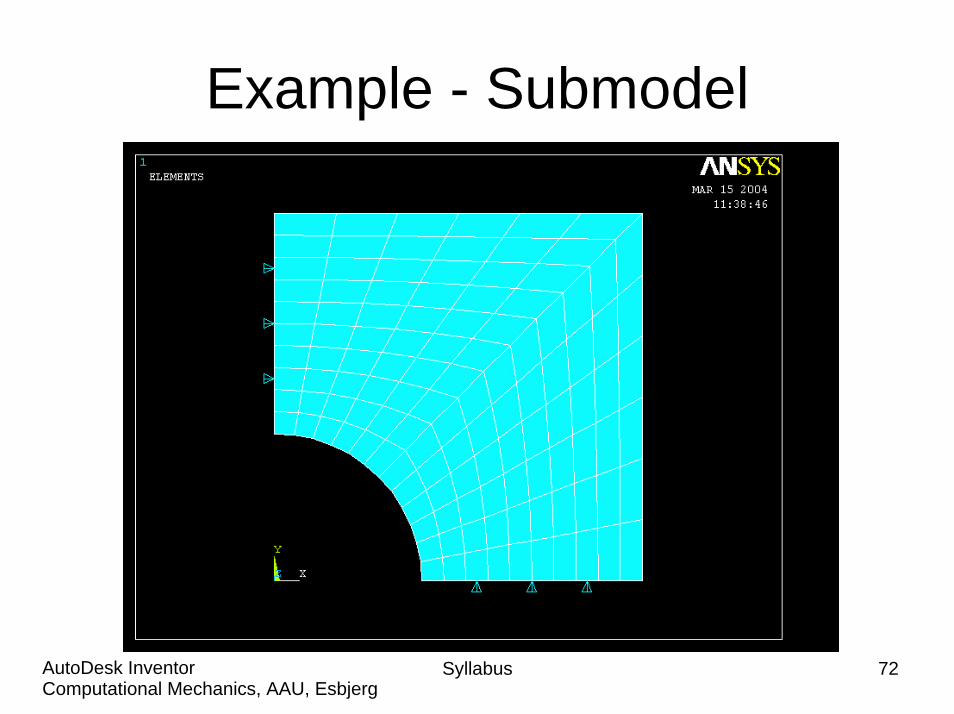
Example - Submodel
Syllabus 72Computational Mechanics, AAU, EsbjergAutoDesk Inventor
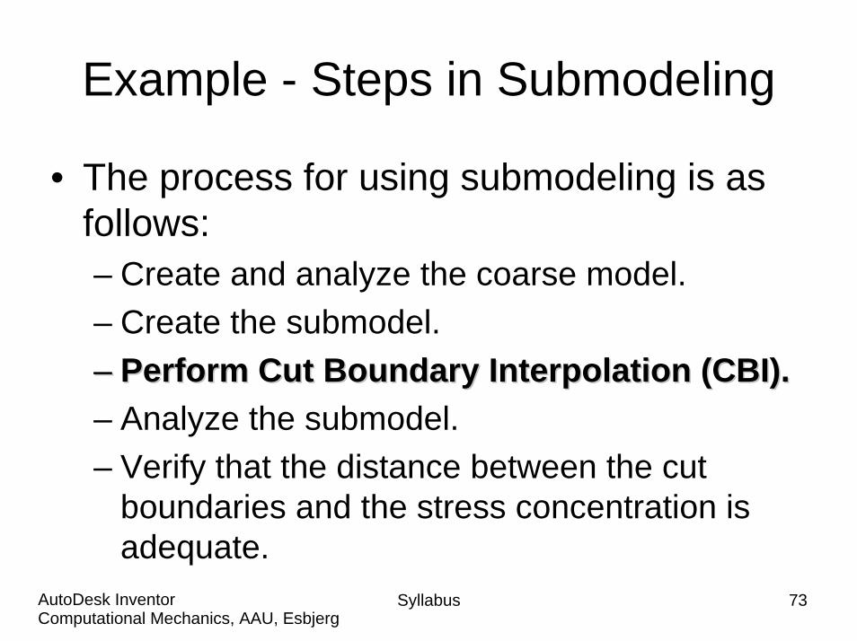
Example - Steps in Submodeling
• The process for using submodeling is as follows: – Create and analyze the coarse model.– Create the submodel.–– Perform Cut Boundary Interpolation (CBI).Perform Cut Boundary Interpolation (CBI).– Analyze the submodel.– Verify that the distance between the cut
boundaries and the stress concentration is adequate.
Syllabus 73Computational Mechanics, AAU, EsbjergAutoDesk Inventor
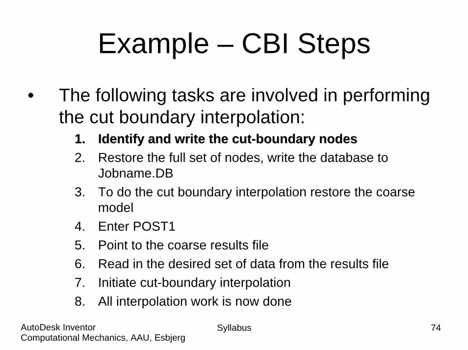
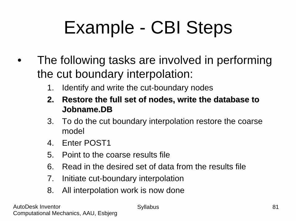
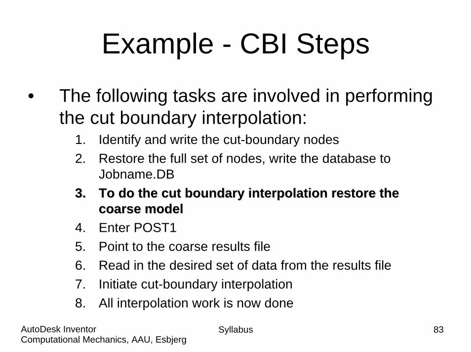
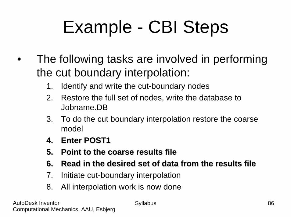
Example – CBI Steps
• The following tasks are involved in performing the cut boundary interpolation:
1.1. Identify and write the cutIdentify and write the cut--boundary nodesboundary nodes2. Restore the full set of nodes, write the database to
Jobname.DB3. To do the cut boundary interpolation restore the coarse
model4. Enter POST15. Point to the coarse results file6. Read in the desired set of data from the results file7. Initiate cut-boundary interpolation8. All interpolation work is now done
Syllabus 74Computational Mechanics, AAU, EsbjergAutoDesk Inventor

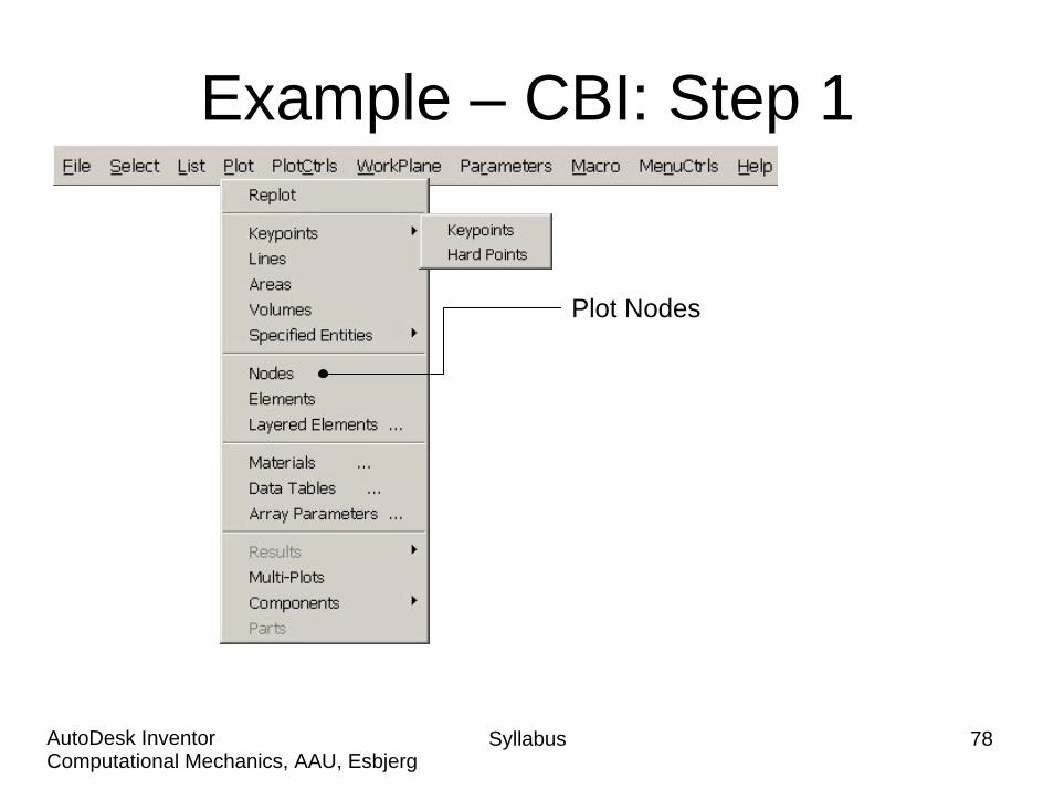
Example – CBI: Step 1
Plot Nodes
Syllabus 75Computational Mechanics, AAU, EsbjergAutoDesk Inventor
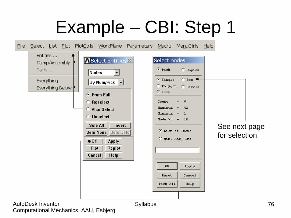
Example – CBI: Step 1
See next page for selection
Syllabus 76Computational Mechanics, AAU, EsbjergAutoDesk Inventor
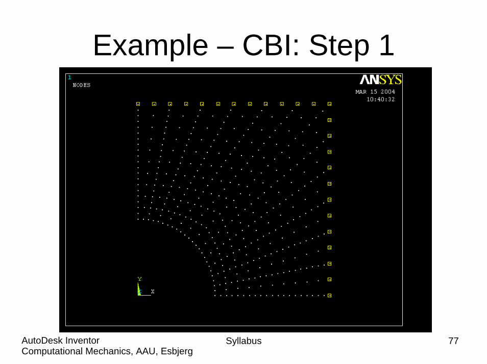
Example – CBI: Step 1
Syllabus 77Computational Mechanics, AAU, EsbjergAutoDesk Inventor
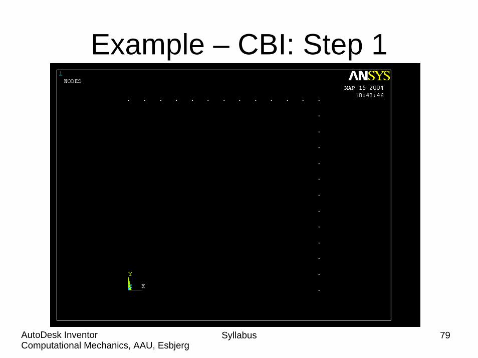
Example – CBI: Step 1
Plot Nodes
Syllabus 78Computational Mechanics, AAU, EsbjergAutoDesk Inventor
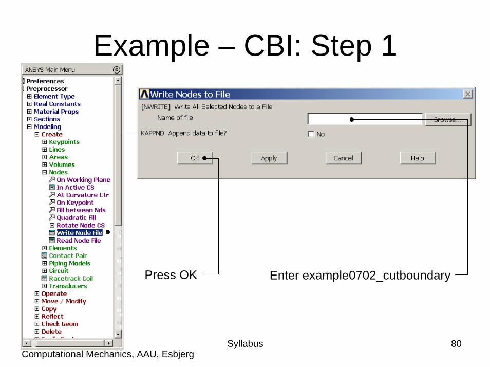
Example – CBI: Step 1
Syllabus 79Computational Mechanics, AAU, EsbjergAutoDesk Inventor
Syllabus 80Computational Mechanics, AAU, EsbjergAutoDesk Inventor
Example – CBI: Step 1
Enter example0702_cutboundaryPress OK
Example - CBI Steps
• The following tasks are involved in performing the cut boundary interpolation:
1. Identify and write the cut-boundary nodes2.2. Restore the full set of nodes, write the database to Restore the full set of nodes, write the database to
Jobname.DBJobname.DB3. To do the cut boundary interpolation restore the coarse
model4. Enter POST15. Point to the coarse results file6. Read in the desired set of data from the results file7. Initiate cut-boundary interpolation8. All interpolation work is now done
Syllabus 81Computational Mechanics, AAU, EsbjergAutoDesk Inventor
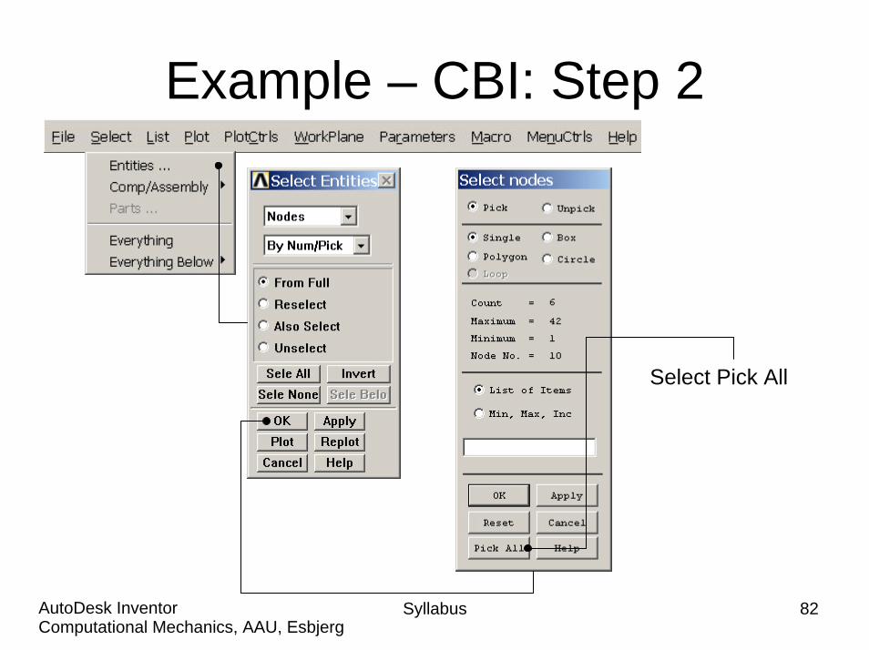
Example – CBI: Step 2
Select Pick All
Syllabus 82Computational Mechanics, AAU, EsbjergAutoDesk Inventor
Example - CBI Steps
• The following tasks are involved in performing the cut boundary interpolation:
1. Identify and write the cut-boundary nodes2. Restore the full set of nodes, write the database to
Jobname.DB3.3. To do the cut boundary interpolation restore the To do the cut boundary interpolation restore the
coarse modelcoarse model4. Enter POST15. Point to the coarse results file6. Read in the desired set of data from the results file7. Initiate cut-boundary interpolation8. All interpolation work is now done
Syllabus 83Computational Mechanics, AAU, EsbjergAutoDesk Inventor
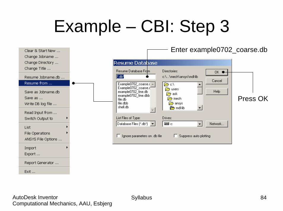
Example – CBI: Step 3Enter example0702_coarse.db
Press OK
Syllabus 84Computational Mechanics, AAU, EsbjergAutoDesk Inventor
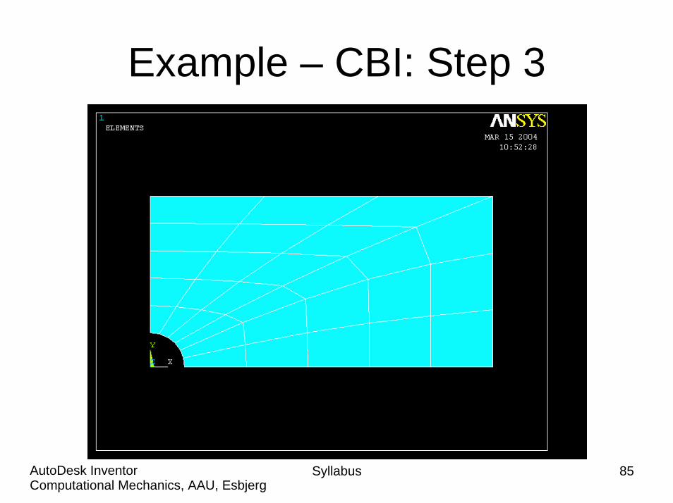
Example – CBI: Step 3
Syllabus 85Computational Mechanics, AAU, EsbjergAutoDesk Inventor
Example - CBI Steps
• The following tasks are involved in performing the cut boundary interpolation:
1. Identify and write the cut-boundary nodes2. Restore the full set of nodes, write the database to
Jobname.DB3. To do the cut boundary interpolation restore the coarse
model4.4. Enter POST1Enter POST15.5. Point to the coarse results filePoint to the coarse results file6.6. Read in the desired set of data from the results fileRead in the desired set of data from the results file7. Initiate cut-boundary interpolation8. All interpolation work is now done
Syllabus 86Computational Mechanics, AAU, EsbjergAutoDesk Inventor
Syllabus 87Computational Mechanics, AAU, EsbjergAutoDesk Inventor
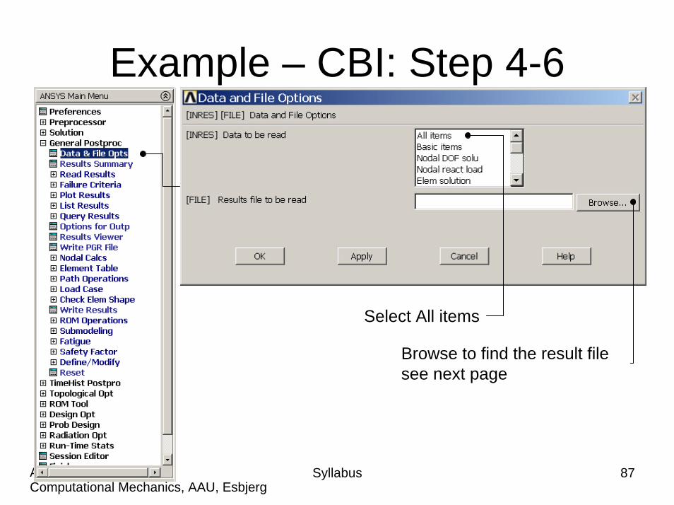
Example – CBI: Step 4-6
Browse to find the result file see next page
Select All items
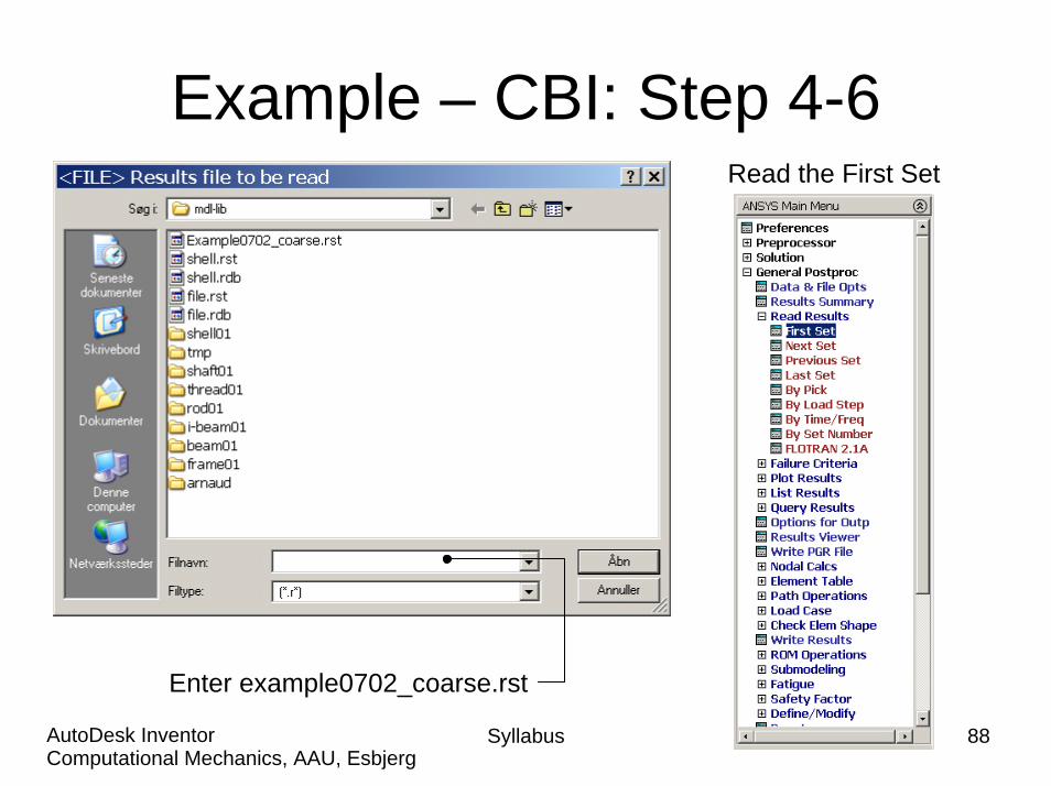
Example – CBI: Step 4-6Read the First Set
Enter example0702_coarse.rst
Syllabus 88Computational Mechanics, AAU, EsbjergAutoDesk Inventor
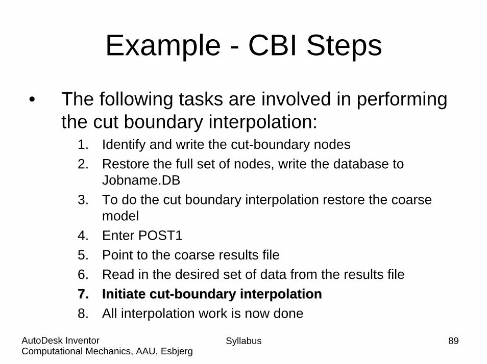
Example - CBI Steps
• The following tasks are involved in performing the cut boundary interpolation:
1. Identify and write the cut-boundary nodes2. Restore the full set of nodes, write the database to
Jobname.DB3. To do the cut boundary interpolation restore the coarse
model4. Enter POST15. Point to the coarse results file6. Read in the desired set of data from the results file7.7. Initiate cutInitiate cut--boundary interpolationboundary interpolation8. All interpolation work is now done
Syllabus 89Computational Mechanics, AAU, EsbjergAutoDesk Inventor
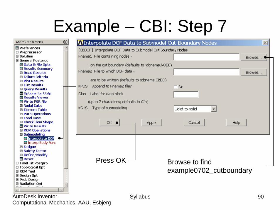
Example – CBI: Step 7
Syllabus 90Computational Mechanics, AAU, EsbjergAutoDesk Inventor
Press OK Browse to find example0702_cutboundary
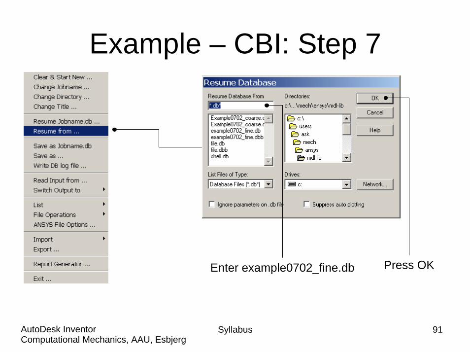
Example – CBI: Step 7
Press OKEnter example0702_fine.db
Syllabus 91Computational Mechanics, AAU, EsbjergAutoDesk Inventor
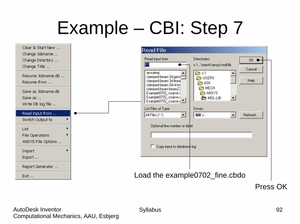
Example – CBI: Step 7
Load the example0702_fine.cbdoPress OK
Syllabus 92Computational Mechanics, AAU, EsbjergAutoDesk Inventor
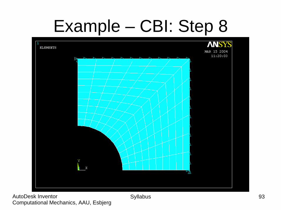
Example – CBI: Step 8
Syllabus 93Computational Mechanics, AAU, EsbjergAutoDesk Inventor
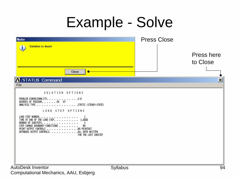
Example - SolvePress Close
Press hereto Close
Syllabus 94Computational Mechanics, AAU, EsbjergAutoDesk Inventor
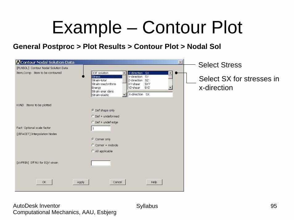
Example – Contour PlotGeneral Postproc > Plot Results > Contour Plot > Nodal Sol
Select Stress
Select SX for stresses in x-direction
Syllabus 95Computational Mechanics, AAU, EsbjergAutoDesk Inventor
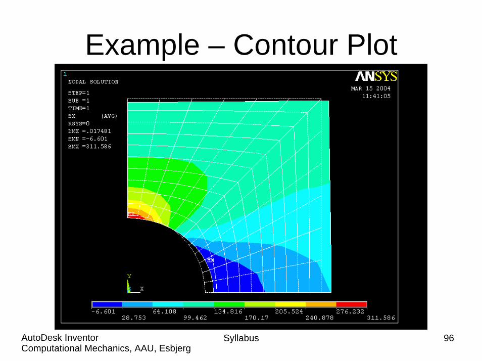
Example – Contour Plot
Syllabus 96Computational Mechanics, AAU, EsbjergAutoDesk Inventor

Example – Select - Entities
See next page for selection
Syllabus 97Computational Mechanics, AAU, EsbjergAutoDesk Inventor
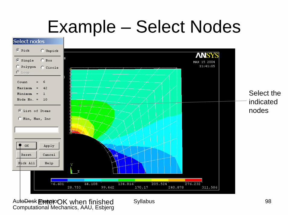
Example – Select Nodes
Select the indicated nodes
Syllabus 98Computational Mechanics, AAU, EsbjergAutoDesk InventorEnter OK when finished

Example – List Results
Syllabus 99Computational Mechanics, AAU, EsbjergAutoDesk Inventor
Select Stress, SCOMP
Press OK
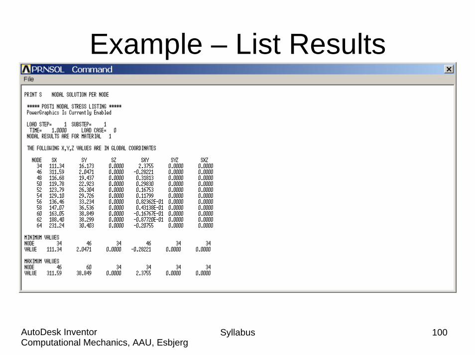
Example – List Results
Syllabus 100Computational Mechanics, AAU, EsbjergAutoDesk Inventor
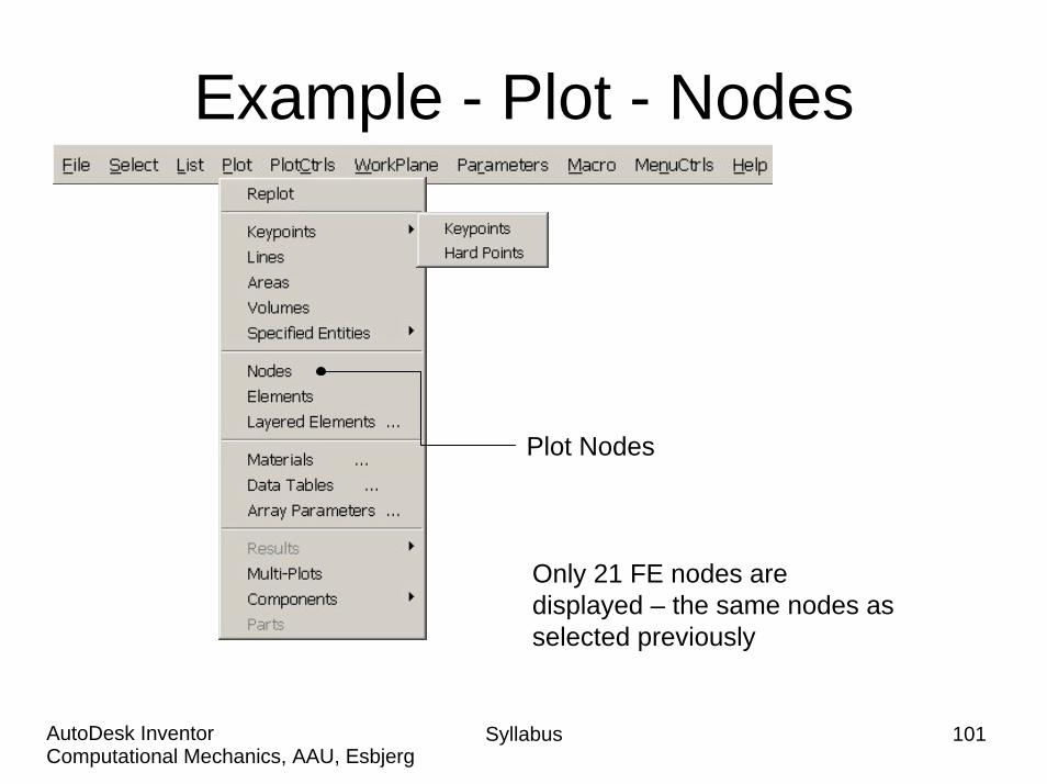
Example - Plot - Nodes
Plot Nodes
Only 21 FE nodes are displayed – the same nodes as selected previously
Syllabus 101Computational Mechanics, AAU, EsbjergAutoDesk Inventor

Example – Select - Entities
Select Pick All
Syllabus 102Computational Mechanics, AAU, EsbjergAutoDesk Inventor
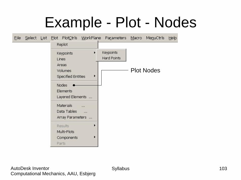
Example - Plot - Nodes
Plot Nodes
Syllabus 103Computational Mechanics, AAU, EsbjergAutoDesk Inventor
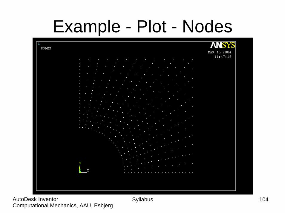
Example - Plot - Nodes
Syllabus 104Computational Mechanics, AAU, EsbjergAutoDesk Inventor

Syllabus 105Computational Mechanics, AAU, EsbjergAutoDesk Inventor
Example – Define Path
See next page for selection
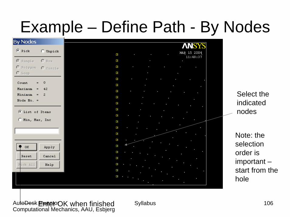
Example – Define Path - By Nodes
Select the indicated nodes
Note: the selection order is important –start from the hole
Syllabus 106Computational Mechanics, AAU, EsbjergAutoDesk InventorEnter OK when finished

Example – Define Path - By Nodes
Enter an appropiate name, e.g. SSX
Enter OK
Syllabus 107Computational Mechanics, AAU, EsbjergAutoDesk Inventor
Syllabus 108Computational Mechanics, AAU, EsbjergAutoDesk Inventor
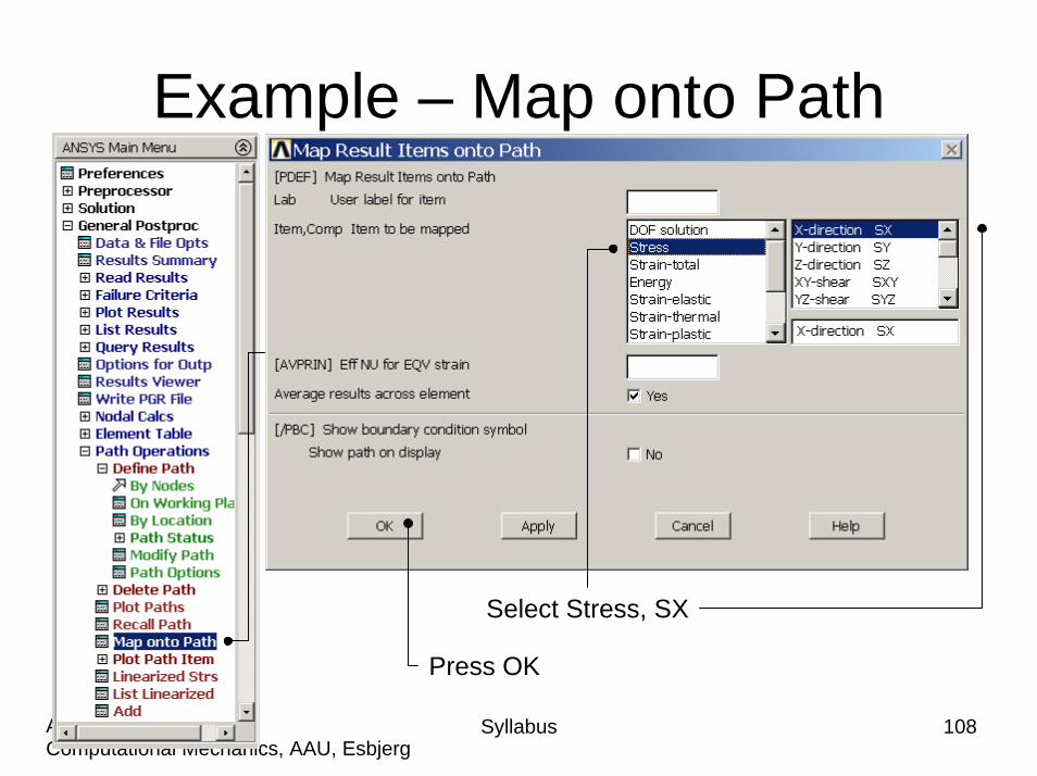
Example – Map onto Path
Select Stress, SX
Press OK
Syllabus 109Computational Mechanics, AAU, EsbjergAutoDesk Inventor
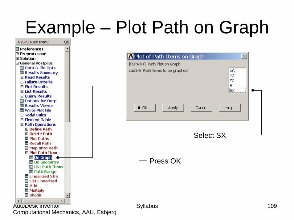
Example – Plot Path on Graph
Select SX
Press OK
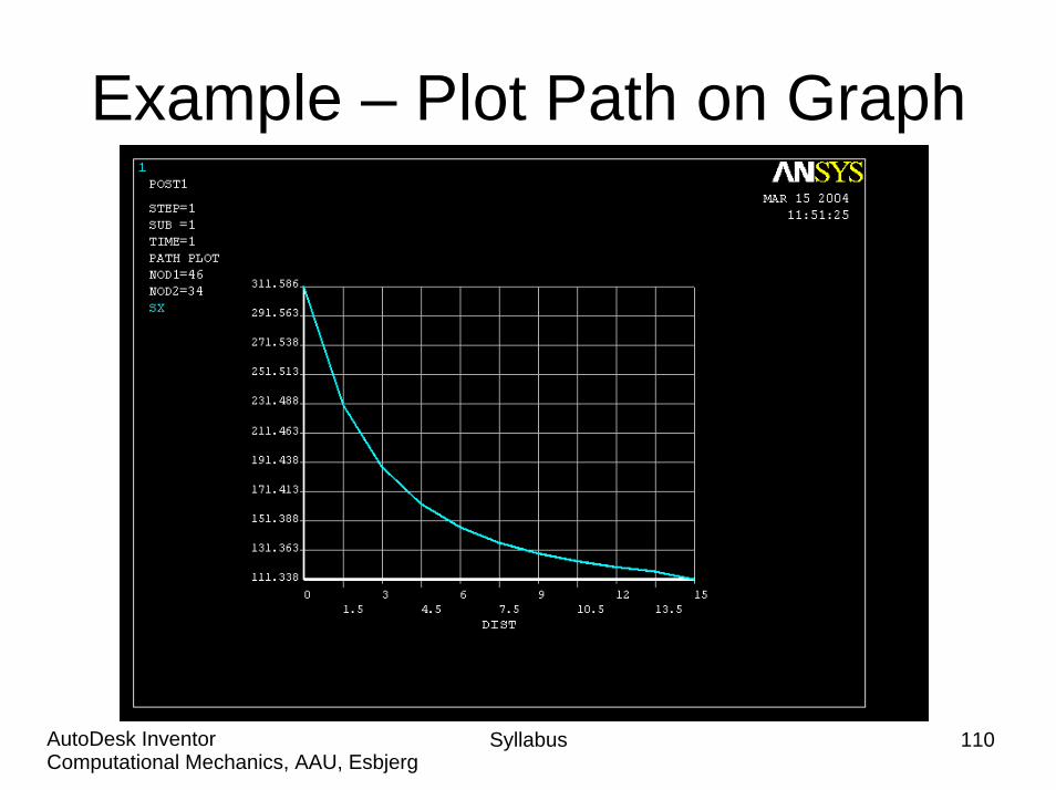
Example – Plot Path on Graph
Syllabus 110Computational Mechanics, AAU, EsbjergAutoDesk Inventor
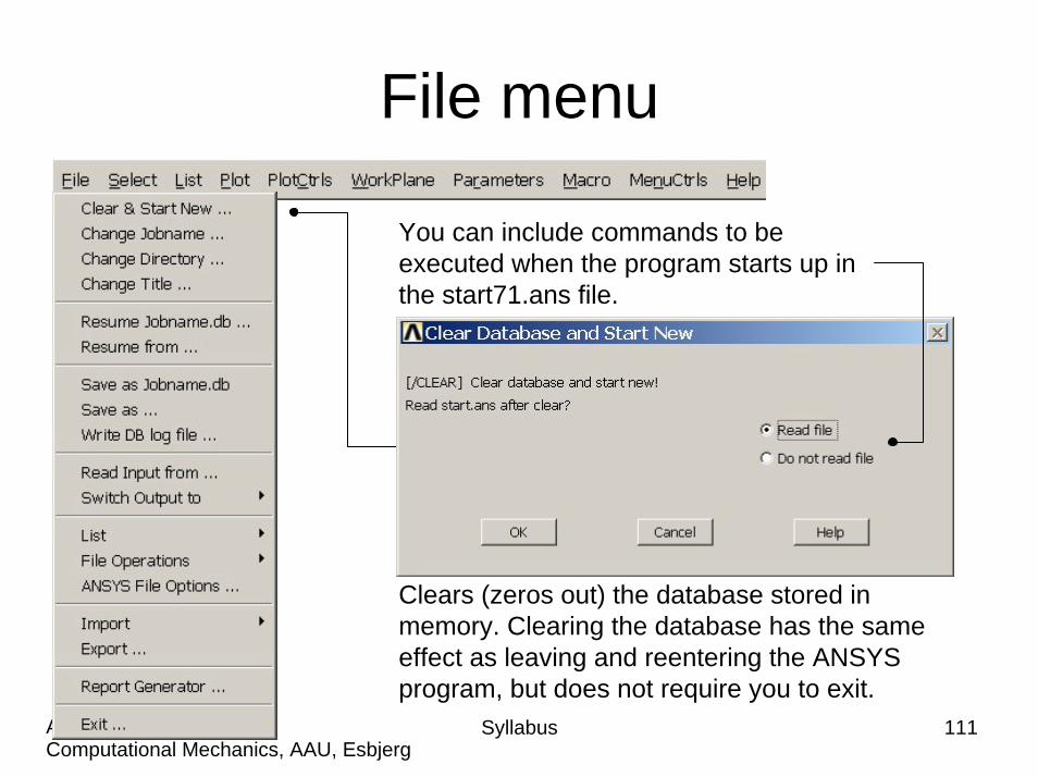
File menu
Syllabus 111Computational Mechanics, AAU, EsbjergAutoDesk Inventor
Clears (zeros out) the database stored in memory. Clearing the database has the same effect as leaving and reentering the ANSYS program, but does not require you to exit.
You can include commands to be executed when the program starts up in the start71.ans file.