Embed Size (px)
Citation preview

Course 1-Day 1
High-Tech Operator Certificate Program Course 1: Treatment and Distribution
Copyright © 2009 AWWA 2
● This course is the first course in a series of three that leads to a High-Tech Operator Certificate.
● This course addresses the devices used to monitor and control processes and equipment in water treatment and distribution systems.● Course 2: Application and Tools reviews the high-tech tools
available for capturing, creating, finding, and using information about facilities, assets, and customers.
● Course 3: Data Management provides an overview of the technologies available for managing information about assets and process performance.
High-Tech Operator Certificate Program
Copyright © 2009 AWWA 3
● Welcome
● Measurement and control symbols, nomenclature, and drawing conventions
● Sensing devices
● On-line analyzers
● Control devices
● Logic circuits, symbols, and conventions
● Closing and sneak peek at day 2
Agenda Day 1 – Welcome
Copyright © 2009 AWWA 4
This course covers the basics of process monitoring and control of water treatment and distribution.
By the end of today, you will be able to:● Describe the differences and similarities between the three key
diagrams used by high-tech operators● Discuss the use of analog and discrete sensing devises from a high-
tech operator perspective● Communicate the function and value of using on-line analyzers● Describe at least two control devices used in high-tech operations● Add new functionality to a loop diagram and explain your perspective
Goals
Copyright © 2009 AWWA 5
● How much experience do we have in this room?
● Introduce yourself ● Your name● Where you work● Current position● Number of years working in the water industry
Getting Acquainted
Copyright © 2009 AWWA 6
● Begin and end on time
● All questions are valid. If you think it, ask
● Respect the opinions of others
● Actively participate
● Today this course is your work; therefore, your full attention is required – Cell phones on silent
● Break times are scheduled; however, if you need to stand or take a break before then please do so
● Have fun!
● What other ground rules should we establish?
Ground Rules
Copyright © 2009 AWWA 7
● Welcome
● Measurement and control symbols, nomenclature, and drawing conventions
● Sensing devices
● On-line analyzers
● Control devices
● Logic circuits, symbols, and conventions
● Closing and sneak peek at day 2
Agenda Day 1 – Measurement…
Copyright © 2009 AWWA 8
Measurement and Control Symbols
● Piping and Instrumentation Diagrams (P&ID)● Shows the interconnection of process equipment and the
instrumentation used to control the process
● Loop Diagrams● Schematic representation of a complete circuit
● Ladder Logic● Symbolic representation of a control scheme● Graphical language for programming Programmable Logic
Controllers (PLC)
Copyright © 2009 AWWA 9
● Symbols are simple geometric shapes with text
● Control symbols and process equipment are arranged conceptually
● Controls and equipment are connected by process and signal lines
Reading Piping and Instrumentation Diagrams (P&ID)
Copyright © 2009 AWWA 10
P&ID – Include
● Instrumentation and designations
● Mechanical equipment with names and numbers
● All valves and their identifications
● Process piping, sizes, and identification
● Miscellaneous - vents, drains, special fittings, sampling lines, reducers, increasers, and swagers
● Permanent start-up and flush lines
● Flow directions
● Interconnections references
● Control inputs and outputs, interlocks
● Interfaces for class changes
● Seismic category
● Quality level
● Annunciation inputs
● Computer control system input
● Vendor and contractor interfaces
● Identification of components and subsystems delivered by others
● Intended physical sequence of the equipment
Copyright © 2009 AWWA 11
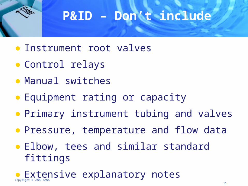
P&ID – Don’t include
● Instrument root valves
● Control relays
● Manual switches
● Equipment rating or capacity
● Primary instrument tubing and valves
● Pressure, temperature and flow data
● Elbow, tees and similar standard fittings
● Extensive explanatory notes
Copyright © 2009 AWWA 12
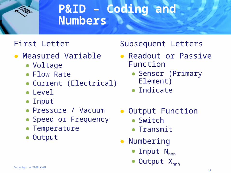
P&ID – Coding and Numbers
First Letter
● Measured Variable ● Voltage● Flow Rate● Current (Electrical)● Level● Input● Pressure / Vacuum● Speed or Frequency● Temperature● Output
Subsequent Letters
● Readout or Passive Function● Sensor (Primary Element)● Indicate
● Output Function● Switch● Transmit
● Numbering● Input Nnnn
● Output Xnnn
Copyright © 2009 AWWA 13
P&ID – Decoding Practice
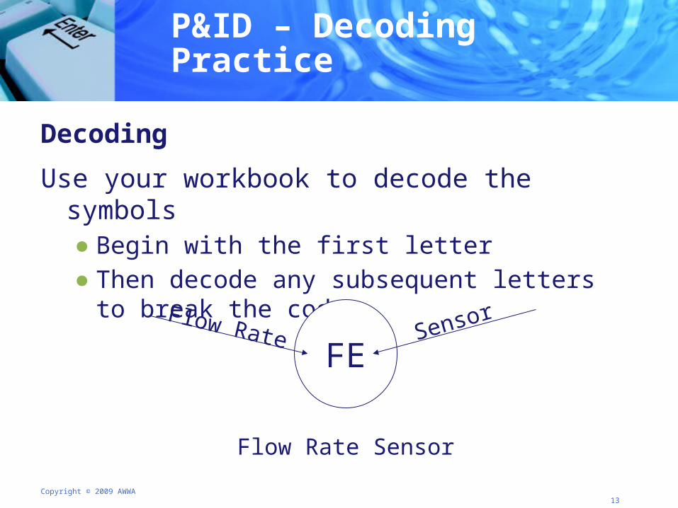
Decoding
Use your workbook to decode the symbols● Begin with the first letter● Then decode any subsequent letters to break the code
FEFlow Rate Sensor
Flow Rate Sensor
Copyright © 2009 AWWA 14
P&ID – Lines
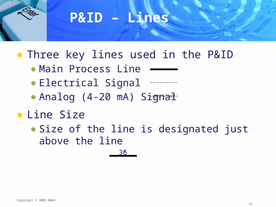
● Three key lines used in the P&ID ● Main Process Line● Electrical Signal● Analog (4-20 mA) Signal
● Line Size● Size of the line is designated just above the line
36”
Copyright © 2009 AWWA 15
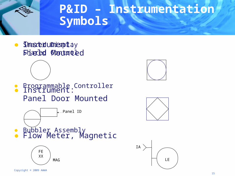
P&ID – Instrumentation Symbols
● Instrument: Field Mounted
● Instrument: Panel Door Mounted
● Flow Meter, Magnetic
● Shared DisplayShared Control
● Programmable Controller
● Bubbler Assembly
Panel ID
FEXX
MAG LE
IA
Copyright © 2009 AWWA 16
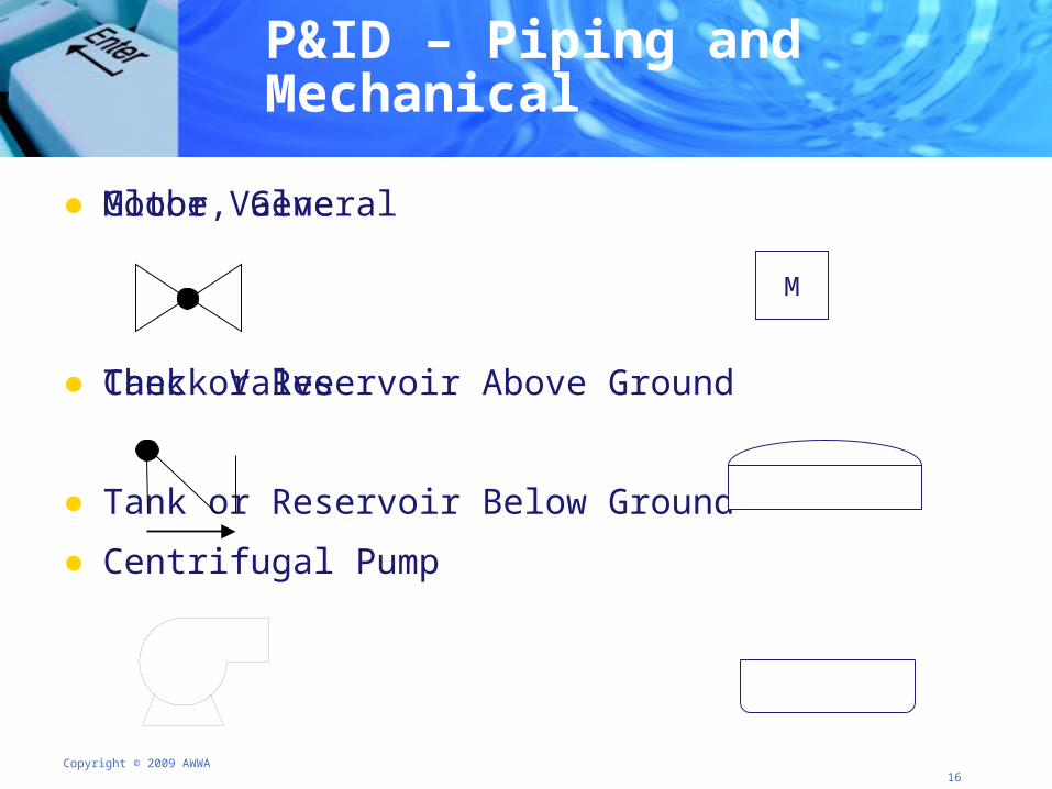
P&ID – Piping and Mechanical
● Globe Valve
● Check Valve
● Centrifugal Pump
● Motor, General
● Tank or Reservoir Above Ground
● Tank or Reservoir Below Ground
M
Copyright © 2009 AWWA 17
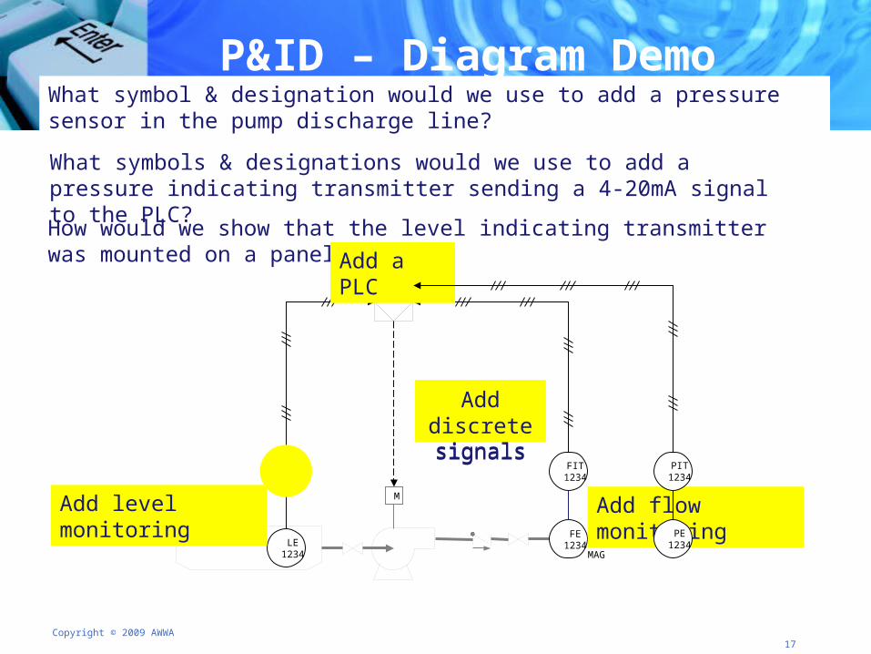
What symbols & designations would we use to add a pressure indicating transmitter sending a 4-20mA signal to the PLC?
What symbol & designation would we use to add a pressure sensor in the pump discharge line?
How would we show that the level indicating transmitter was mounted on a panel door?
P&ID – Diagram Demo
M
LE1234
LIT1234
FE1234
MAG
FIT1234
Add level monitoring Add flow monitoring
Add a PLC
Add analog signals
Add discrete signals
PE1234
PIT1234
Copyright © 2009 AWWA 18
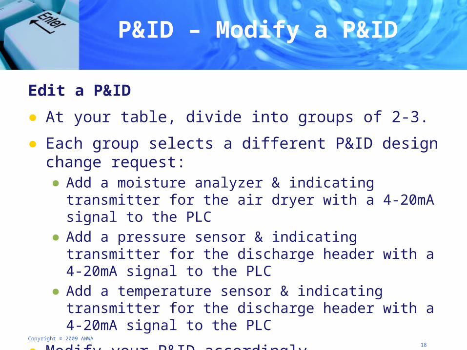
P&ID – Modify a P&ID
Edit a P&ID
● At your table, divide into groups of 2-3.
● Each group selects a different P&ID design change request:● Add a moisture analyzer & indicating transmitter for the air dryer with a
4-20mA signal to the PLC● Add a pressure sensor & indicating transmitter for the discharge header
with a 4-20mA signal to the PLC● Add a temperature sensor & indicating transmitter for the discharge
header with a 4-20mA signal to the PLC
● Modify your P&ID accordingly.
● Be prepared to share your completed P&ID.
Copyright © 2009 AWWA 19
Loop Diagrams – Defined
● P&ID applies to the whole process loop.
● Loop diagrams give further information on the control loop of an individual parameter – an extension of the P&ID.● Symbolically represents a single control loop identifying
control components and interconnections● May need a combination of loops on one drawing● May document electrical or pneumatic instruments or a
combination of both
Copyright © 2009 AWWA 20
Loop Diagrams – Symbols
● Created after the P&ID is completed
● Symbols used for P&ID are suitable for loop diagrams but are expanded to include ● Connection points● Power sources● Instrument actions and ranges● Safety features
● Balloons connect to P&ID
Copyright © 2009 AWWA 21
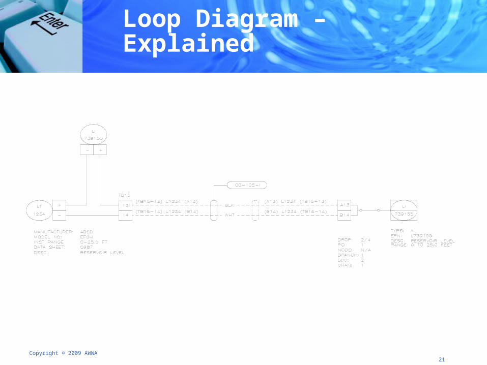
Loop Diagram – Explained
Copyright © 2009 AWWA 22
Measurement & Control Symbols Summary
● What is the difference between a P&ID and Loop diagram?
● At your table list as many distinctions between the two as you can in five minutes.
Copyright © 2009 AWWA 23
● Welcome
● Measurement and control symbols, nomenclature, and drawing conventions
● Sensing devices
● On-line analyzers
● Control devices
● Logic circuits, symbols, and conventions
● Closing and sneak peek at day 2
Agenda Day 1: Sensing Devices
Copyright © 2009 AWWA 24
Sensing Devices – Analog & Discrete
● Analog Output Devices● Continuous detection of flow, level, or pressure● Meters display measured value● Varying current between 4 and 20 mA
● Discrete● Detection of current threshold● Switches generate a discrete (on/off) signal that recognizes
a high/low process condition
● Combine analog and discrete
Copyright © 2009 AWWA 25
Analog Sensing Devices – Flow
● Control the delivery (both volume and flow)
● Provide control signals ● For automatic or manual adjustment● For mechanical processes
● Provide flow signals to control flow● Control valves● Variable-speed pumps● Variable unit processes or multiple process units
Copyright © 2009 AWWA 26
Analog Sensing Devices – Flow
● Displacement Meters● Measure the velocity of flow ● Convert into volume of flow for usage
● Velocity Meters● Residential and small commercial applications ● Positive Displacement or "PD" meters
● Electromagnetic Meters● Technically a velocity type water meter ● Uses electromagnetic properties to determine flow velocity
Copyright © 2009 AWWA 27
Analog Sensing Devices – Pressure
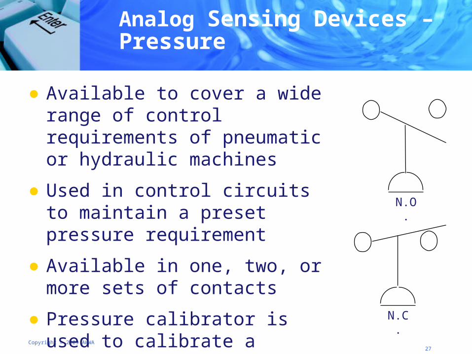
● Available to cover a wide range of control requirements of pneumatic or hydraulic machines
● Used in control circuits to maintain a preset pressure requirement
● Available in one, two, or more sets of contacts
● Pressure calibrator is used to calibrate a pressure switch
N.O.
N.C.
Copyright © 2009 AWWA 28
Analog Sensing Devices – Level
● A variety of materials and alloys are used today to combat harsh environments such as oils, acids, and extremes of temperature and pressure
● Numerous level sensing devices incorporating numerous technologies are available
● Used to detect liquid level inside a container or in its natural form
● Can be either continuous or point values
Copyright © 2009 AWWA 29
Analog Sensing Devices – Level Types
● Point level detection devices● Floats
● Continuous or point level detection devices● Capacitance ● Hydrostatic and load cells
● Continuous level detection devices● Bubbler ● Ultrasound● Microwave and Radar
Copyright © 2009 AWWA 30
Sensing Devices – Floats
Float Level Monitors
● Floats are mechanical level monitors● Data can be manually transmitted (line & pulley)● Data can be electronically transmitted
● Works well for buried tanks
● Upper and lower limits can be measured
Copyright © 2009 AWWA 31
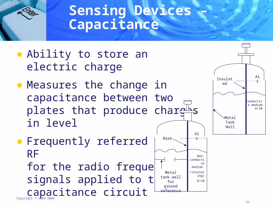
Sensing Devices – Capacitance
● Ability to store an electric charge
● Measures the change in capacitance between two plates that produce charges in level
● Frequently referred to as RF for the radio frequency signals applied to the capacitance circuit
Non- conductive
medium
(insulating)
K<10
AirBare
Metal tank wall for ground
reference
Conductive medium
K>10
AirInsulated
Metal Tank Wall
Copyright © 2009 AWWA 32
Sensing Devices – Hydrostatic
Hydrostatic Level Monitors and Load Cells
● Indicates water levels and volume, especially when primary access to the tanks is at the same level as the tank bottom.
● Load cells are electronic devices (transducer) that are used to convert a force into an electrical signal.
● Properly calibrate for depth, gravity of liquid, temperature, and/or barometric pressure.
Copyright © 2009 AWWA 33
Sensing Devices – Bubblers
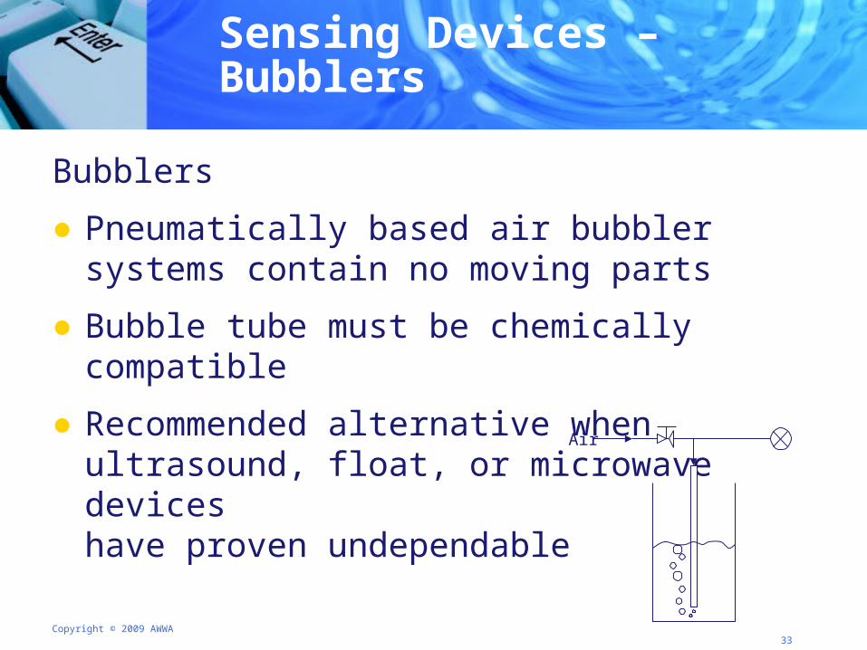
Bubblers
● Pneumatically based air bubbler systems contain no moving parts
● Bubble tube must be chemically compatible
● Recommended alternative when ultrasound, float, or microwave devices have proven undependable
Air
Copyright © 2009 AWWA 34
Sensing Devices – Ultrasound
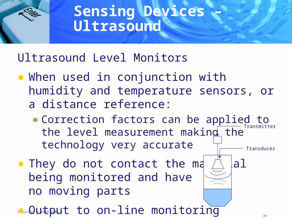
Ultrasound Level Monitors
● When used in conjunction with humidity and temperature sensors, or a distance reference:● Correction factors can be applied to the level measurement
making the technology very accurate
● They do not contact the material being monitored and haveno moving parts
● Output to on-line monitoring
Transmitter
Transducer
Copyright © 2009 AWWA 35
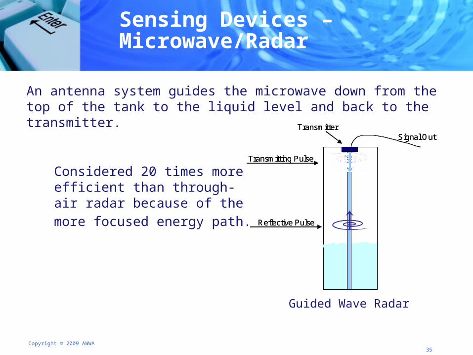
Sensing Devices – Microwave/Radar
Considered 20 times more efficient than through-air radar because of the more focused energy path.
Transmitting Pulse
Reflective Pulse
Signal OutTransmitter
Transmitting Pulse
Reflective Pulse
Signal OutTransmitter
Guided Wave Radar
An antenna system guides the microwave down from the top of the tank to the liquid level and back to the transmitter.
Copyright © 2009 AWWA 36
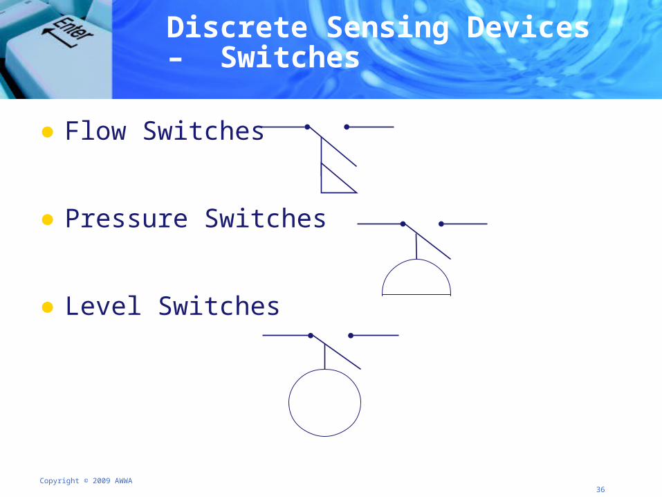
Discrete Sensing Devices – Switches
● Flow Switches
● Pressure Switches
● Level Switches
Copyright © 2009 AWWA 37
Sensing Devices – Your Turn
In groups of 3-4 discuss the following
● Which types of level devices do you currently use?
● What problems (if any) have you had with level sensors?
● How were they solved? Were different types of sensors installed?
Copyright © 2009 AWWA 38
● Welcome
● Measurement and control symbols, nomenclature, and drawing conventions
● Sensing devices
● On-line analyzers
● Control devices
● Logic circuits, symbols, and conventions
● Closing and sneak peek at day 2
Agenda Day 1 – On-line Analyzers
Copyright © 2009 AWWA 39
On-line Analyzers
● Measures physical, chemical, and biological water-quality parameters
● Measures different variables either simultaneously or sequentially
● Monitors material content at various stages in flotation or other mineral-processing flow sheets
● Allows for material balance accounting on a continuous basis
Copyright © 2009 AWWA 40
On-line Analyzers – Conductivity & Turbidity
● Conductivity Meters● Indicate the amount of electrolyte present● Monitor salt increases and quality changes in river water and
tap water
● Turbidimeters ● Measure the amount of impurities in relatively broad terms● Used to check the raw, treated, and distributed water● Used to determine coagulant and coagulant aid automatic
injection rates
Copyright © 2009 AWWA 41
On-line Analyzers - pH & ORP
● pH Analyzers● Electronically measures electrode potential of a water solution and
directly converts the reading to a pH level● Determines coagulant aid injection rates and water treatment
process monitoring
● ORP (Oxidation Reduction Potential) Analyzers● Similar to pH analyzers – some contain a pH electrode as a
reference● Output signal from the probe is processed by an external
transmitter and sent to the SCADA system or remote display
Copyright © 2009 AWWA 42
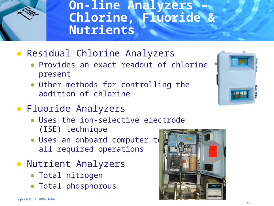
On-line Analyzers – Chlorine, Fluoride & Nutrients
● Residual Chlorine Analyzers● Provides an exact readout of chlorine present● Other methods for controlling the addition of chlorine
● Fluoride Analyzers● Uses the ion-selective electrode (ISE) technique● Uses an onboard computer to perform all required operations
● Nutrient Analyzers● Total nitrogen● Total phosphorous
Copyright © 2009 AWWA 43
On-line Analyzers – Your Turn
Why invest in an on-line analyzer?
Directions: 1. At your table discuss the above question in relationship to your
work environment.
2. Define 2-3 reasons why upper management should consider investing in an on-line analyzer of your choice.
3. Be prepared to share your suggestions with the class.
Copyright © 2009 AWWA 44
● Welcome
● Measurement and control symbols, nomenclature, and drawing conventions
● Sensing devices
● On-line analyzers
● Control devices
● Logic circuits, symbols, and conventions
● Closing and sneak peek at day 2
Agenda Day 1- Control Devices
Copyright © 2009 AWWA 45
Control Devices –Motor Starter
● Starter characteristics● Heavy duty relay contains overload protection● 110 VAC energizes coil that closes the 208, 220, 440, etc.
VAC contacts supplying power to motor ● Energized through push button, relay, or discrete output
(from PLC)
● Two types of starters● Autotransformer starters ● Solid-state starters
Copyright © 2009 AWWA 46
Control Devices – Speed Control
● Hydraulic Drives● Pumps, motors, and drives
● Variable Speed Drives (VSD)● Benefits
● Energy savings
● Improved process control
● Improved reliability ● Drawbacks
● Structural resonance
● Rotor dynamics
Copyright © 2009 AWWA 47
Control Devices - Actuators
● Introduce motion or clamp an object so as to prevent motion
● Subdivision of transducers
● Transform an input signal (mainly an electrical signal) into motion
Copyright © 2009 AWWA 48
● Hard-wired, relay-based controllers
● Computer-based controllers● Single loop● Multi-loop ● Supervisory set-point● Distributed network
Control Devices – Controllers and Loops
Copyright © 2009 AWWA 49
● Welcome
● Measurement and control symbols, nomenclature, and drawing conventions
● Sensing devices
● On-line analyzers
● Control devices
● Logic circuits, symbols, and conventions
● Closing and sneak peek at day 2
Agenda Day 1 – Logic Circuits
Copyright © 2009 AWWA 50
Logic Circuits – Ladder Logic
● Method of drawing electrical logic schematics
● Graphical language for programming Programmable Logic Controllers (PLC)
● Useful for ● Simple but critical control systems● Reworking old hardwired relay circuits● Very complex automated systems
● Rule-based language not procedural language● Each rung on the ladder represents a rule
Copyright © 2009 AWWA 51
Ladder Logic - Pros and Cons
● Best suited for control problems requiring binary variables
● Complex rungs are best broken into simpler steps
● Manufacturers vary in ladder logic languages and may not be completely compatible
Copyright © 2009 AWWA 52
Ladder Logic - Symbols
● Manual Switches
● Automatic Level Switches
● Indicating Device Symbols
● Relay Symbols
● Timer Relay Symbols
Copyright © 2009 AWWA 53
Ladder Logic - Manual Switches
● Used to make, break, or change connections in a circuit
● Voltage rating required
● Push-button and selector switches most common● Push-button momentary contact switches make or break
sets of contacts only while pressed ● Selector switches are rotated to different positions to make,
break, or change connections
Copyright © 2009 AWWA 54
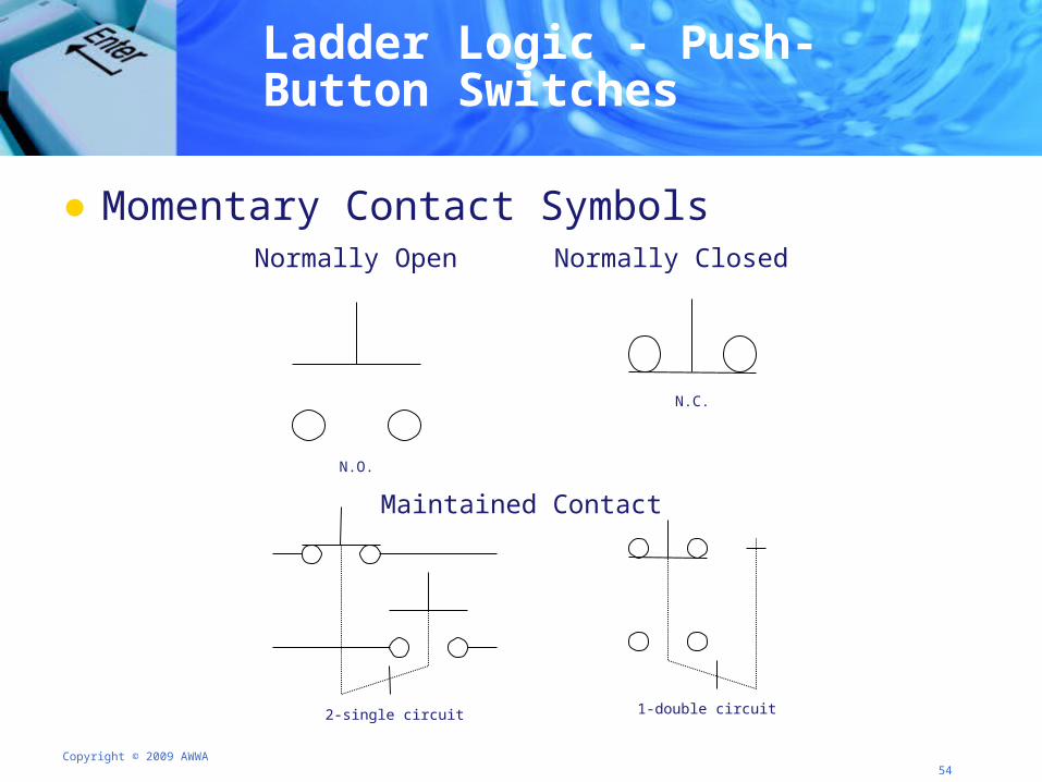
Ladder Logic - Push-Button Switches
● Momentary Contact SymbolsNormally Open Normally Closed
Maintained Contact
N.O.
N.C.
2-single circuit 1-double circuit
Copyright © 2009 AWWA 55
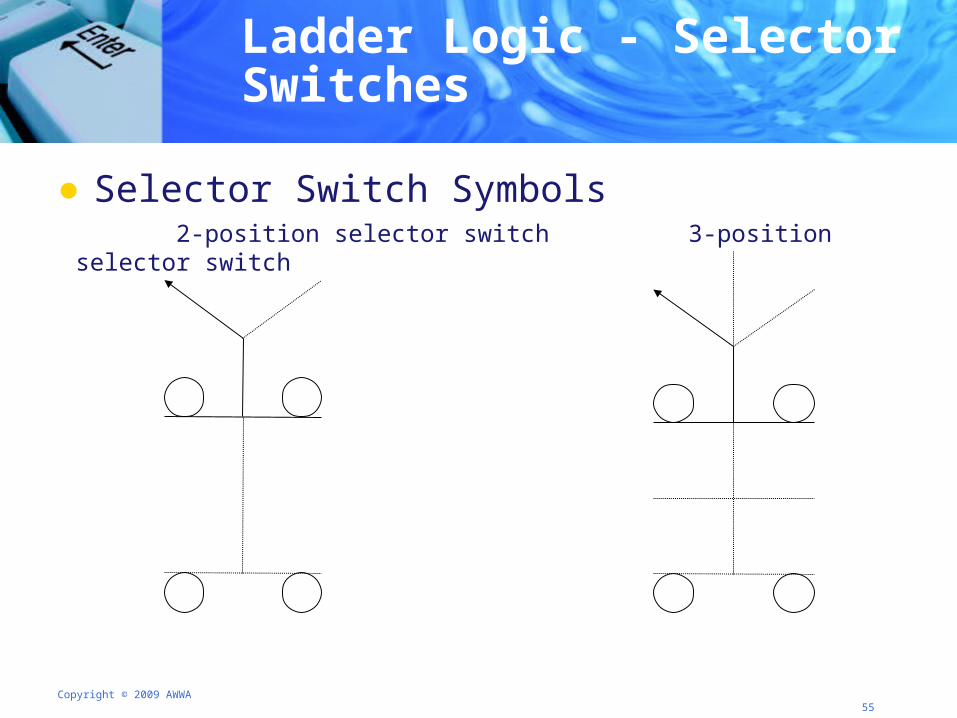
Ladder Logic - Selector Switches
● Selector Switch Symbols 2-position selector switch 3-position selector switch
Copyright © 2009 AWWA 56
● Level switches are automatic switches used to● Control fluid levels in processes ● Make or break a circuit when the fluid rises above (or drops
below) a preset level
● Level switches are used in the control circuits of ● Pumps● Valves ● Alarm indicators
Ladder Logic - Level Switches
Copyright © 2009 AWWA 57
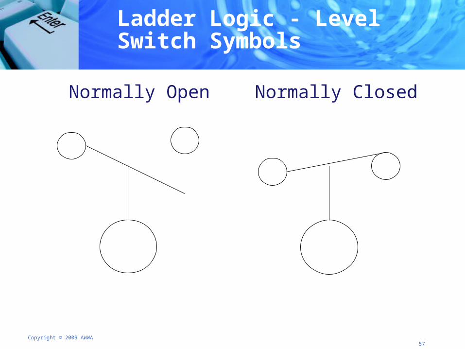
Ladder Logic - Level Switch Symbols
Normally Open Normally Closed
Copyright © 2009 AWWA 58
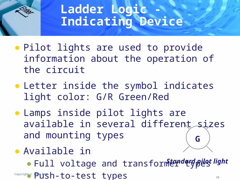
● Pilot lights are used to provide information about the operation of the circuit
● Letter inside the symbol indicates light color: G/R Green/Red
● Lamps inside pilot lights are available in several different sizes and mounting types
● Available in ● Full voltage and transformer types ● Push-to-test types
Ladder Logic - Indicating Device
G
Standard pilot light
Copyright © 2009 AWWA 59
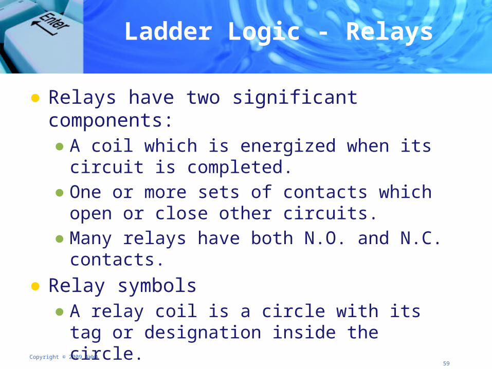
● Relays have two significant components: ● A coil which is energized when its circuit is completed.● One or more sets of contacts which open or close other
circuits.● Many relays have both N.O. and N.C. contacts.
● Relay symbols● A relay coil is a circle with its tag or designation inside the
circle. ● The contacts have the same tag or designation as the coil.
Ladder Logic - Relays
Copyright © 2009 AWWA 60
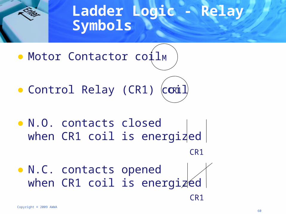
Ladder Logic - Relay Symbols
● Motor Contactor coil
● Control Relay (CR1) coil
● N.O. contacts closed when CR1 coil is energized
● N.C. contacts opened when CR1 coil is energized
CR1
CR1
CR1
M
Copyright © 2009 AWWA 61
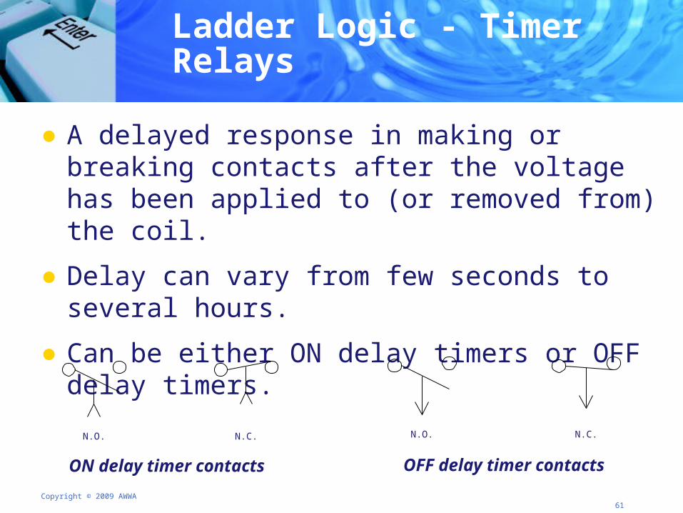
Ladder Logic - Timer Relays
● A delayed response in making or breaking contacts after the voltage has been applied to (or removed from) the coil.
● Delay can vary from few seconds to several hours.
● Can be either ON delay timers or OFF delay timers.
N.O. N.C.
ON delay timer contacts
N.O. N.C.
OFF delay timer contacts
Copyright © 2009 AWWA 62
Ladder Logic - Summary
● Ladder diagrams are a common method for describing control circuits
● A ladder diagram contains information, expressed by component symbols, about the way the control circuit functions and in what sequence different events take place
● Ladder diagrams describe the sequence of operation of circuit, system, or a whole process
Copyright © 2009 AWWA 63
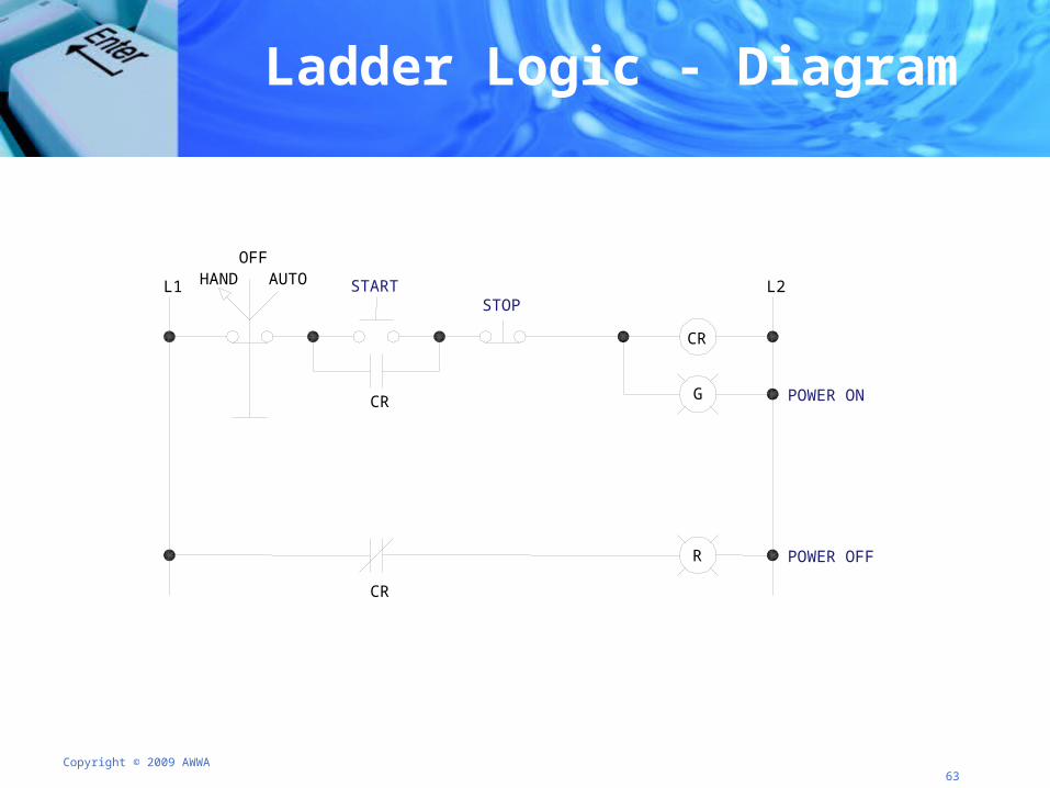
Ladder Logic - Diagram
POWER ON
POWER OFF
STOPSTART
CR
CR
CR
R
G
HANDOFF
AUTOL1 L2
Copyright © 2009 AWWA 64
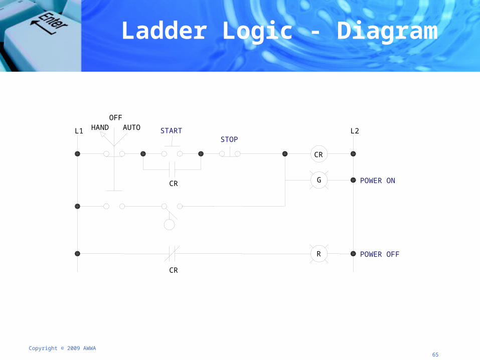
Ladder Logic – Add a Rung
● Using the diagram in your workbooks, add a rung to the ladder diagram● Draw a rung automatically starting on high ● Add an N.O. float switch to energize CR
● Be prepared to discuss what your next addition to this ladder logic would be
Copyright © 2009 AWWA 65
Ladder Logic - Diagram
POWER ON
POWER OFF
STOPSTART
CR
CR
CR
R
G
HANDOFF
AUTOL1 L2
Copyright © 2009 AWWA 66
● Welcome
● Measurement and control symbols, nomenclature, and drawing conventions
● Sensing devices
● On-line analyzers
● Control devices
● Logic circuits, symbols, and conventions
● Closing and sneak peek at day 2
Agenda Day 1 – Closing
Copyright © 2009 AWWA 67
● Review
● Tomorrow● SCADA systems● Control modes● Tracking process performance● Alarm management● Standards ● Control rooms, environments, enclosures
● Evaluations
Closing and Sneak Peek at Day 2