Embed Size (px)
Citation preview
www.renold.com
CouplingsResilient and Soft Start Couplings
www.renold.com
Contents
Page 01
Page No
Renold Gears 02
Renold Couplings 03
Typical Applications 04
The Renold Collection 06
Coupling Comparison Chart 08
Coupling Selection Guide 10
Load Classification by Application 12
Service Factors and Selection 13
Keyway and Keyway Dimensions 14
Taper Bushes 15
Spiderflex 16
Spider 19
Pinflex 20
Crownpin 25
Tyreflex 28
Discflex 31
Chainflex 34
Rigid 36
Gearflex 37
Renoldflex 51
Hydrastart 56
Terms and Conditions 68
Renold Chain inside back cover

www.renold.com
Superior Gear & Coupling Technology
InterchangeabilityMany of the products fromRenold Gears are dimensionallyinterchangeable with othermanufacturers gear units,allowing a trouble freereplacement of gearboxes,in most cases upgrading thecapacity through state of theart technology and materials.
Custom MadeRenold Gears is unique in it’sability to offer custom madeproducts designed to meetcustomers exactingrequirements withoutcompromise on availability andcost. From complete packagesolutions to individual precisionreplacement gears, all can betailor made to meet specificapplicational requirements.
AvailableThe most popular ranges ofgearboxes are available fromlocal distribution stock, backedup by extensive stocks from ourmanufacturing plant in the UK.
Strength through ServiceRenold Gears has been manufacturing high quality, high specification gear units for over100 years and has always been at the leading edge of gear technology with innovativeproducts and power transmission solutions.
Page 03
Renold Couplings
www.renold.com
Service Excellence and CareRenold offers a unique level of service excellence and customer care. Our experienced applications engineers will select the optimum solution, with the aid of the latest computer and design technology.
Specialist Solutions and InnovationsRenold is recognised throughout the industry for its capability to create specific solutions to customers unique requirements. International companies and industries, from steel to food processing to escalators to textile machinery, have chosen Renold to solve their problems.
Leading edge technologyRenold provides practical cost effective solutions with a commitment to value through quality. This is achieved by the continuous investment in people, process technology and manufacturing.
Consistent ReliabilityRenold’s 100 years of experience in the design and manufacturing of power
transmission products to the highest specifications, with proven performance in diverse industries world-wide, underwrites the guaranteed quality and the assurance of reliability.
Renold Clutches & Couplings is BS EN ISO 9001:2000 approved. All products are designed and manufactured to this Quality Assurance System.
TestingAlthough each of our factories manufacturing and testing demandsvary, the following capabilities are available if the application demands it:
• Full scale radial and axial stiffness measurement.
• Torsional vibration analysis.
• Misalignment testing of couplings up to 2 metres diameter.
• Measurements of torsional stiffness up to 220 KNM.
• Static and dynamic balancing capabilities.
• Noise attenuation testing.
• Transient and finite element analysis.
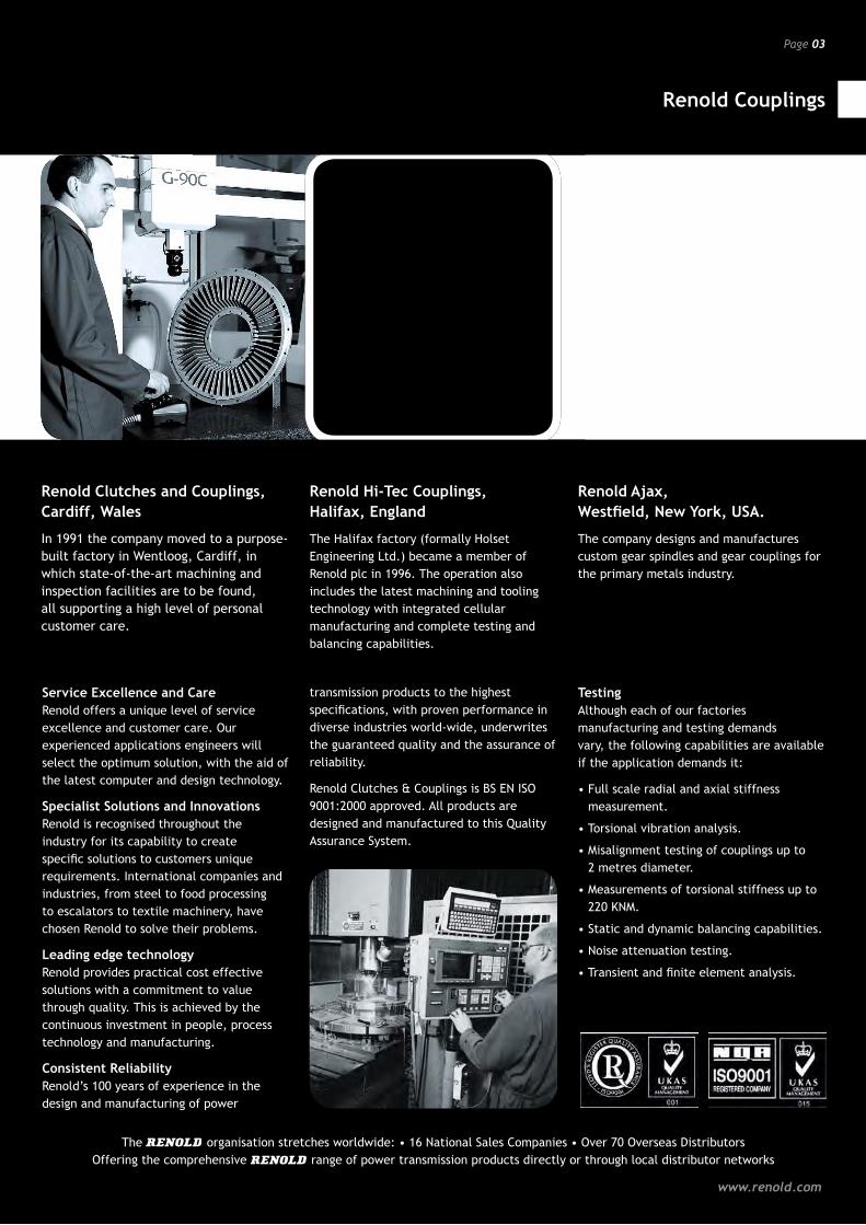
Renold have been manufacturing flexible and rigid couplings, sprag and air clutches for over 50 years. The Renold Couplings factories are based in three global locations - Cardiff, Wales; Halifax, England and Westfield, New York, USA.
Renold Clutches and Couplings, Cardiff, Wales
In 1991 the company moved to a purpose-built factory in Wentloog, Cardiff, in which state-of-the-art machining and inspection facilities are to be found, all supporting a high level of personal customer care.
Renold Hi-Tec Couplings, Halifax, England
The Halifax factory (formally Holset Engineering Ltd.) became a member of Renold plc in 1996. The operation also includes the latest machining and tooling technology with integrated cellular manufacturing and complete testing and balancing capabilities.
Renold Ajax, Westfield, New York, USA.
The company designs and manufactures custom gear spindles and gear couplings for the primary metals industry.
The organisation stretches worldwide: • 16 National Sales Companies • Over 70 Overseas Distributors Offering the comprehensive range of power transmission products directly or through local distributor networks
Typical Applications
Resilient and Soft Start Couplings
Page 04
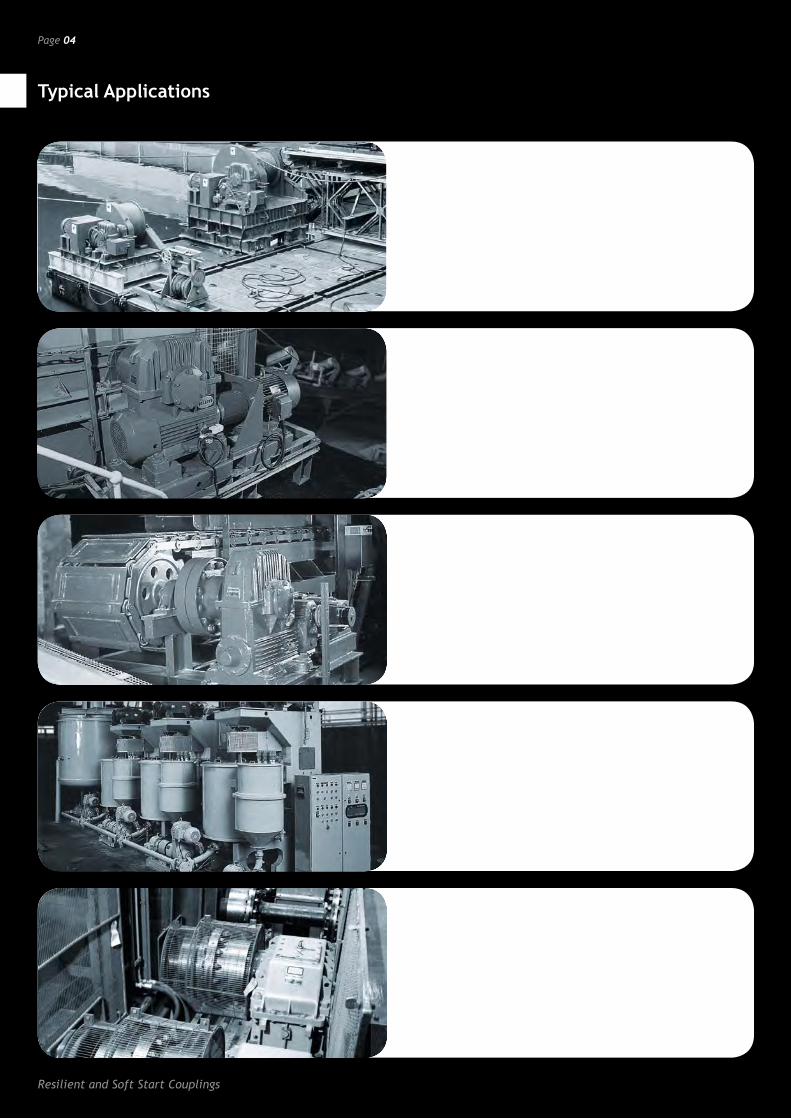
HydrastartA fluid coupling suitable for soft starting high inertia machinery with reduced current demand, controlled acceleration and torque with drive overload protection.
• Conveyors • Rotary Kilns
• Ball Mills • Fans
• Centrifuges
PinflexA robust general purpose pin/buffer coupling, providing reliable fail safe transmission of torque and misalignment capability.
• Pumps
• Compressors
• Conveyors
Crown PinAn established pin/buffer coupling offering extended power capacity where the demand for long life and simplicity of construction make it suitable for working in arduous conditions.
• Conveyors • Washers
• Pumps • Screens
• Cranes • General Industrial Applications
Spider CouplingsRelatively low power but highly flexible coupling with halfbodies in either cast iron or bronze, making suitable for use in the food or chemical/pharmaceutical industries.
• Pumps
• Mixers
• Lube Systems
GearflexHeavy duty all metal couplings giving maximum power capacity within minimum space envelope and excellent misalignment capacity.
• Steelworks
• Quarries
• Mining
Page 05
Typical Applications
www.renold.com
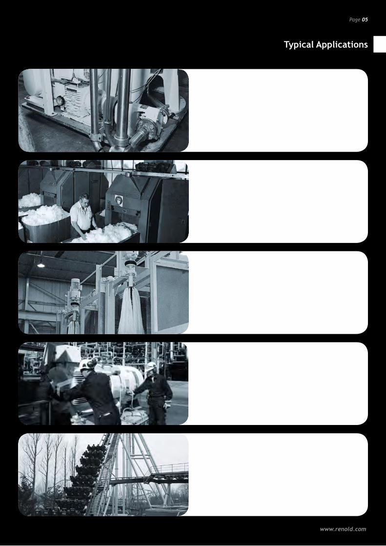
DiscflexA general purpose, fail safe, torsionally flexible coupling offering the option of either urethane or reinforced rubber disc.
• Pumps • Compressors
• Conveyors • Mixers
SpiderflexA medium powered, torsionally flexible coupling, combining shock absorbing and misalignment. Used in the widest range of industries and applications.
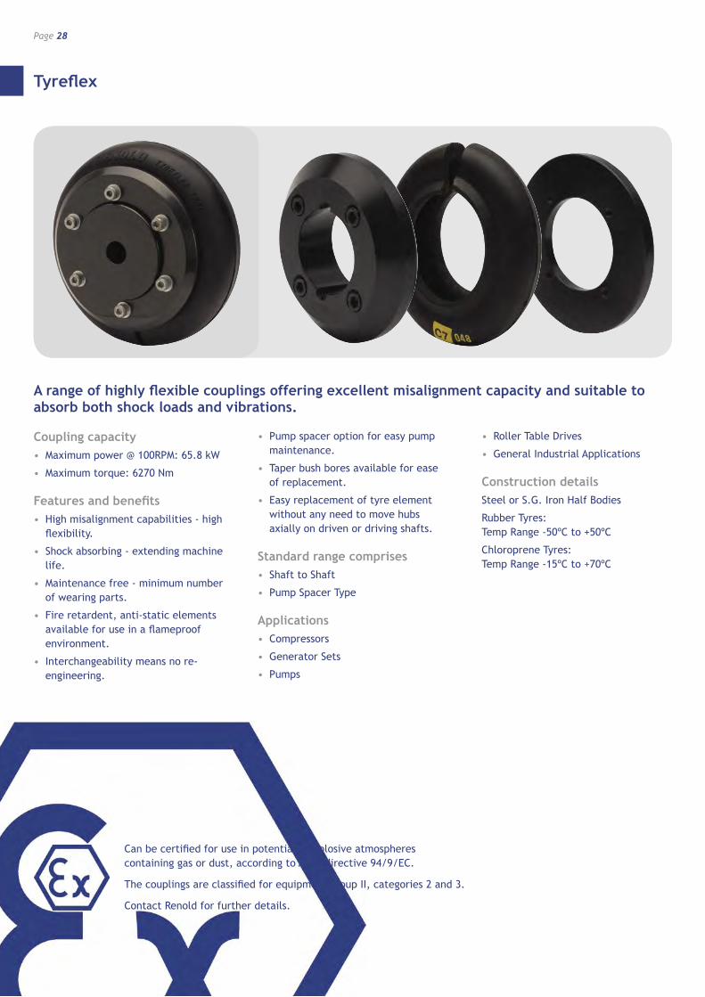
TyreflexA range of highly flexible couplings offering excellent misalignment capacity and suitable to absorb both shock loads and vibrations.
• Pumps • Compressors
• Diesel engines • Roller tables
RenoldflexRenoldflex is a torsionally rigid coupling (TRC) that utilises a stainless steel spring disc pack to provide a positive “backlash free” drive.
• Pumps • Compressors • Packaging machines • High temp boiler feeds • Wind Turbines • Petrochemical pump installations • High speed general installations
Coupling customisationRenold is able to offer a full customisation service across its complete range of coupling and clutch products.
Page 06
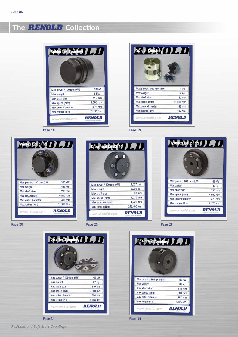
Max power / 100 rpm (kW) 33 kW
Max weight 63 kg
Max shaft size 115 mm
Max speed (rpm) 7,700 rpm
Max outer diameter 275 mm
Max torque (Nm) 3,150 Nm
Spiderflex Coupling
www.renold.com
The Collection
Max power / 100 rpm (kW) 1 kW
Max weight 4 kg
Max shaft size 42 mm
Max speed (rpm) 11,000 rpm
Max outer diameter 95 mm
Max torque (Nm) 107 Nm
Spider Coupling
www.renold.com
Max power / 100 rpm (kW) 340 kW
Max weight 423 kg
Max shaft size 260 mm
Max speed (rpm) 6,800 rpm
Max outer diameter 490 mm
Max torque (Nm) 32,500 Nm
Pinflex Coupling
www.renold.com
Max power / 100 rpm (kW) 2,607 kW
Max weight 2,250 kg
Max shaft size 300 mm
Max speed (rpm) 6,210 rpm
Max outer diameter 1,220 mm
Max torque (Nm) 249,400 Nm
Crownpin Coupling
www.renold.com
Max power / 100 rpm (kW) 66 kWMax weight 49 kgMax shaft size 150 mmMax speed (rpm) 4,500 rpm Max outer diameter 470 mmMax torque (Nm) 6,270 Nm
Tyreflex Coupling
www.renold.com
Max power / 100 rpm (kW) 45 kW
Max weight 67 kg
Max shaft size 110 mm
Max speed (rpm) 2,900 rpm
Max outer diameter 324 mm
Max torque (Nm) 4,298 Nm
Discflex Coupling
www.renold.com
Max power / 100 rpm (kW) 90 kWMax weight 85 kgMax shaft size 140 mmMax speed (rpm) 3,500 rpm Max outer diameter 357 mmMax torque (Nm) 8,595 Nm
Chainflex Coupling
www.renold.com
Page 16 Page 19
Page 20 Page 25 Page 28
Page 31 Page 34
Resilient and Soft Start Couplings
www.renold.com
Page 07
The Collection
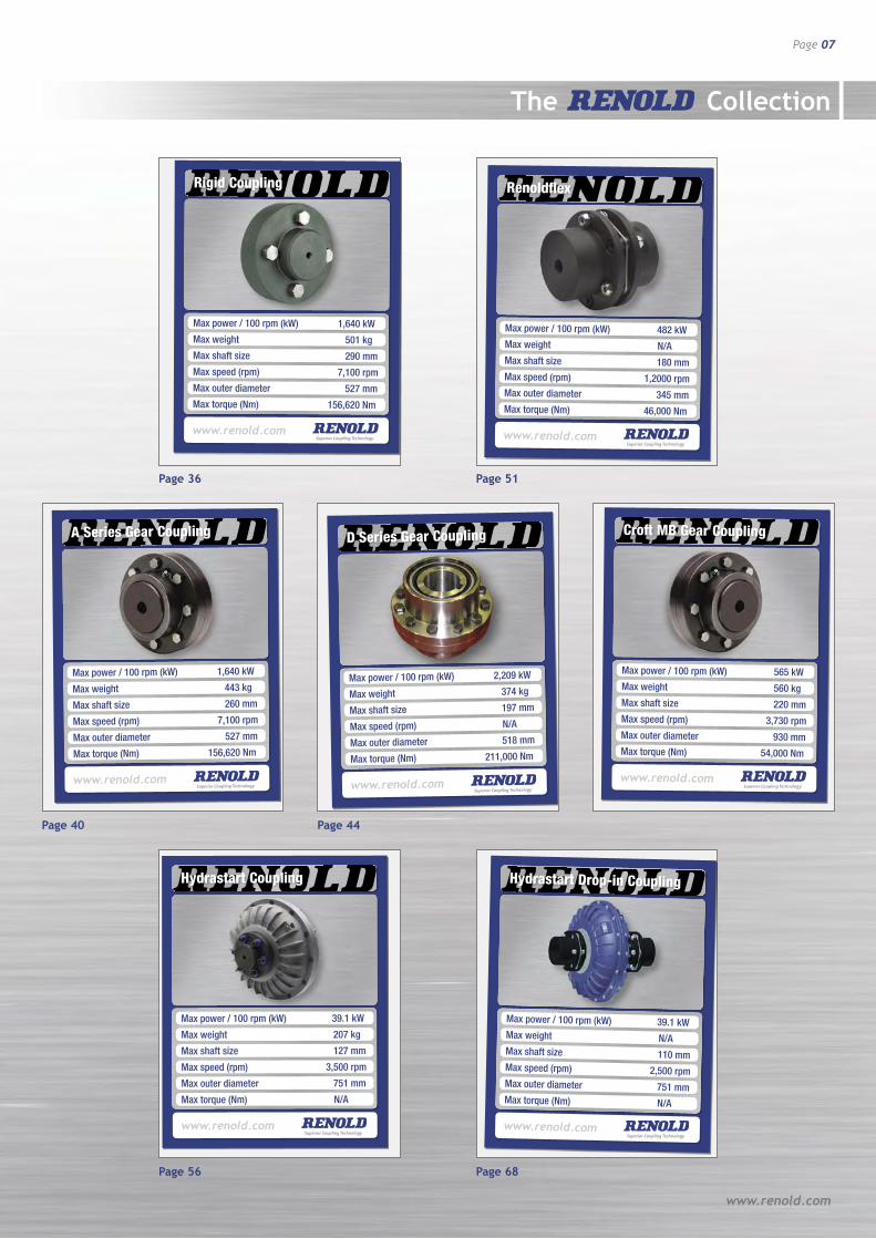
Max power / 100 rpm (kW) 1,640 kW
Max weight 443 kg
Max shaft size 260 mm
Max speed (rpm) 7,100 rpm
Max outer diameter 527 mm
Max torque (Nm) 156,620 Nm
A Series Gear Coupling
www.renold.com
Max power / 100 rpm (kW) 39.1 kW
Max weight 207 kg
Max shaft size 127 mm
Max speed (rpm) 3,500 rpm
Max outer diameter 751 mm
Max torque (Nm) N/A
Hydrastart Coupling
www.renold.com
Max power / 100 rpm (kW) 482 kWMax weight N/AMax shaft size 180 mmMax speed (rpm) 1,2000 rpm Max outer diameter 345 mmMax torque (Nm) 46,000 Nm
Renoldflex
www.renold.com
Max power / 100 rpm (kW) 39.1 kWMax weight N/AMax shaft size 110 mmMax speed (rpm) 2,500 rpm Max outer diameter 751 mmMax torque (Nm) N/A
Hydrastart Drop-in Coupling
www.renold.com
Page 36 Page 51
Page 40 Page 44
Page 56 Page 68
Max power / 100 rpm (kW) 1,640 kW
Max weight 501 kg
Max shaft size 290 mm
Max speed (rpm) 7,100 rpm
Max outer diameter 527 mm
Max torque (Nm) 156,620 Nm
Rigid Coupling
www.renold.com
Max power / 100 rpm (kW) 2,209 kW
Max weight 374 kg
Max shaft size 197 mm
Max speed (rpm) N/A
Max outer diameter 518 mm
Max torque (Nm) 211,000 Nm
D Series Gear Coupling
www.renold.com
Max power / 100 rpm (kW) 565 kWMax weight 560 kgMax shaft size 220 mmMax speed (rpm) 3,730 rpm Max outer diameter 930 mmMax torque (Nm) 54,000 Nm
Croft MB Gear Coupling
www.renold.com
Coupling Comparison Chart
Page 08
Resilient and Soft Start Couplings
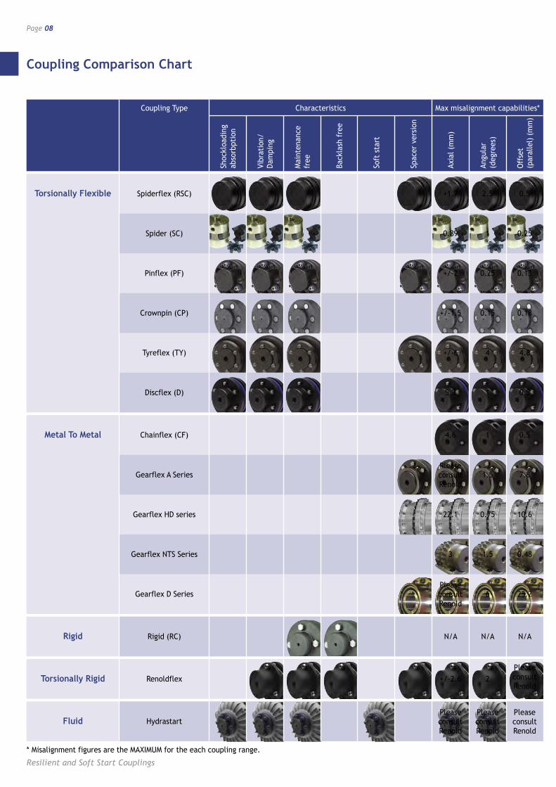
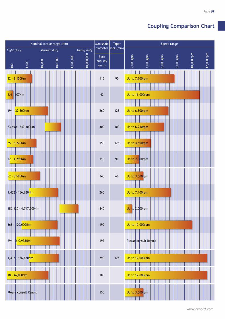
Coupling Type Characteristics Max misalignment capabilities* Nominal torque range (Nm) Max shaft Taper Speed range
Light duty Medium duty Heavy duty diameter lock (mm)
Bore
and key
(mm)
Torsionally Flexible Spiderflex (RSC) +1.7 2.5 0.5 32 – 3,150Nm 115 90 Up to 7,700rpm
Spider (SC) 0.89 1 0.25 2.4 – 107Nm 42 Up to 11,000rpm
Pinflex (PF) +/-2 0.25 0.13 194 – 32,500Nm 260 125 Up to 6,800rpm
Crownpin (CP) +/-1.5 0.15 0.18 23,490 – 249,400Nm 300 100 Up to 6,210rpm
Tyreflex (TY) +/-6 4 4.8 25 – 6,270Nm 150 125 Up to 4,500rpm
Discflex (D) 5.3 1 0.5 72 – 4,298Nm 110 90 Up to 2,900rpm
Metal To Metal Chainflex (CF) 4.6 1 0.5 52 – 8,595Nm 140 60 Up to 3,500rpm
Gearflex A Series 1.5 7.8 1,432 – 156,620Nm 260 Up to 7,100rpm
Gearflex HD series 22.1 0.75 10.6 185,120 – 4,747,000Nm 840 Up to 2,000rpm
Gearflex NTS Series 3 1.5 0.48 668 – 120,000Nm 190 Up to 10,000rpm
Gearflex D Series 6 25.2 294 – 210,938Nm 197 Please consult Renold
Rigid Rigid (RC) N/A N/A N/A 1,432 – 156,620Nm 290 125 Up to 12,000rpm
Torsionally Rigid Renoldflex +/-2.6 2 18 – 46,000Nm 180 Up to 12,000rpm
Fluid Hydrastart Please consult Renold 150 Up to 3,500rpm
Shoc
kloa
ding
ab
sorb
ptio
n
Vibr
atio
n/
Dam
ping
Mai
nten
ance
fr
ee
Back
lash
fre
e
Soft
sta
rt
Spac
er v
ersi
on
Axia
l (m
m)
Angu
lar
(d
egre
es)
Off
set
(par
alle
l) (
mm
)
* Misalignment figures are the MAXIMUM for the each coupling range.
Please consult Renold
Please consult Renold
Please consult Renold
Please consult Renold
Please consult Renold
Please consult Renold
Coupling Comparison Chart
www.renold.com
Page 09
Coupling Type Characteristics Max misalignment capabilities* Nominal torque range (Nm) Max shaft Taper Speed range
Light duty Medium duty Heavy duty diameter lock (mm)
Bore
and key
(mm)
Torsionally Flexible Spiderflex (RSC) +1.7 2.5 0.5 32 – 3,150Nm 115 90 Up to 7,700rpm
Spider (SC) 0.89 1 0.25 2.4 – 107Nm 42 Up to 11,000rpm
Pinflex (PF) +/-2 0.25 0.13 194 – 32,500Nm 260 125 Up to 6,800rpm
Crownpin (CP) +/-1.5 0.15 0.18 23,490 – 249,400Nm 300 100 Up to 6,210rpm
Tyreflex (TY) +/-6 4 4.8 25 – 6,270Nm 150 125 Up to 4,500rpm
Discflex (D) 5.3 1 0.5 72 – 4,298Nm 110 90 Up to 2,900rpm
Metal To Metal Chainflex (CF) 4.6 1 0.5 52 – 8,595Nm 140 60 Up to 3,500rpm
Gearflex A Series 1.5 7.8 1,432 – 156,620Nm 260 Up to 7,100rpm
Gearflex HD series 22.1 0.75 10.6 185,120 – 4,747,000Nm 840 Up to 2,000rpm
Gearflex NTS Series 3 1.5 0.48 668 – 120,000Nm 190 Up to 10,000rpm
Gearflex D Series 6 25.2 294 – 210,938Nm 197 Please consult Renold
Rigid Rigid (RC) N/A N/A N/A 1,432 – 156,620Nm 290 125 Up to 12,000rpm
Torsionally Rigid Renoldflex +/-2.6 2 18 – 46,000Nm 180 Up to 12,000rpm
Fluid Hydrastart Please consult Renold 150 Up to 3,500rpm
100
1,00
0
10,0
00
100,
000
1,00
0,00
0
10,0
00,0
00
2,00
0 rp
m
4,00
0 rp
m
6,00
0 rp
m
8,00
0 rp
m
10,0
00 r
pm
12,0
00 r
pm
Coupling Selection Guide
Page 10
Resilient and Soft Start Couplings
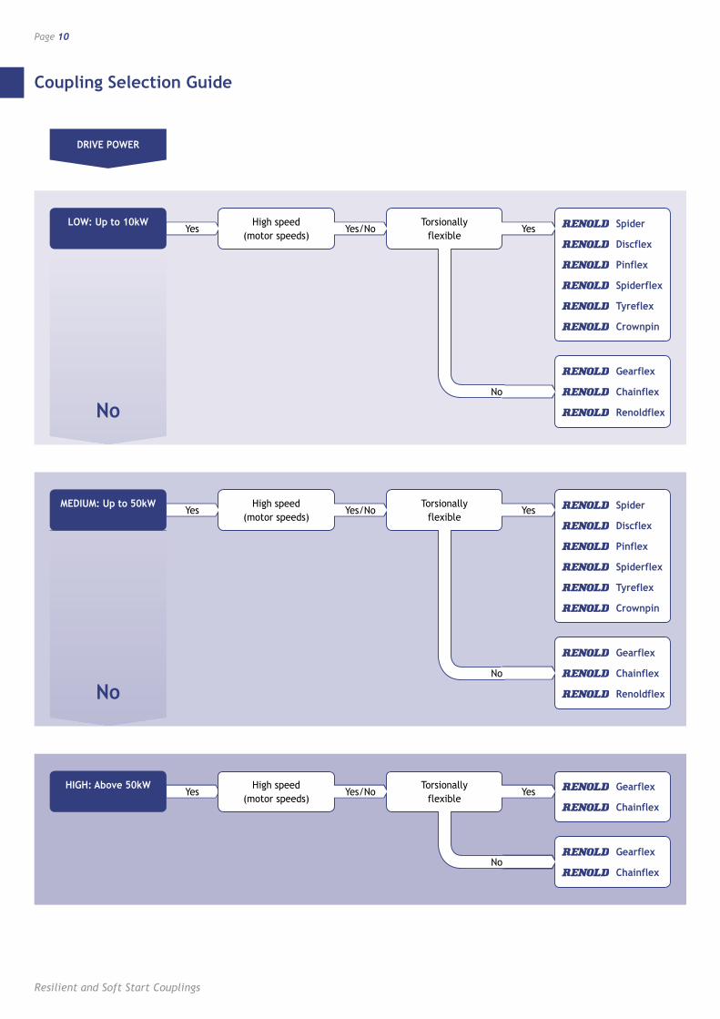
DRIVE POWER
High speed (motor speeds)
Torsionally flexible
Spider
Discflex
Pinflex
Spiderflex
Tyreflex
Crownpin
Gearflex
Chainflex
Renoldflex
Gearflex
Chainflex
Renoldflex
Gearflex
Chainflex
No
No
LOW: Up to 10kW
High speed (motor speeds)
Torsionally flexible
Spider
Discflex
Pinflex
Spiderflex
Tyreflex
Crownpin
MEDIUM: Up to 50kW
High speed (motor speeds)
Torsionally flexible
Chainflex
HIGH: Above 50kW Gearflex
Yes YesYes/No
No
Yes YesYes/No
No
Yes Yes/No
No
Yes
Coupling Selection Guide
www.renold.com
Page 11
At installation all couplings should be aligned as near to perfect as possible.
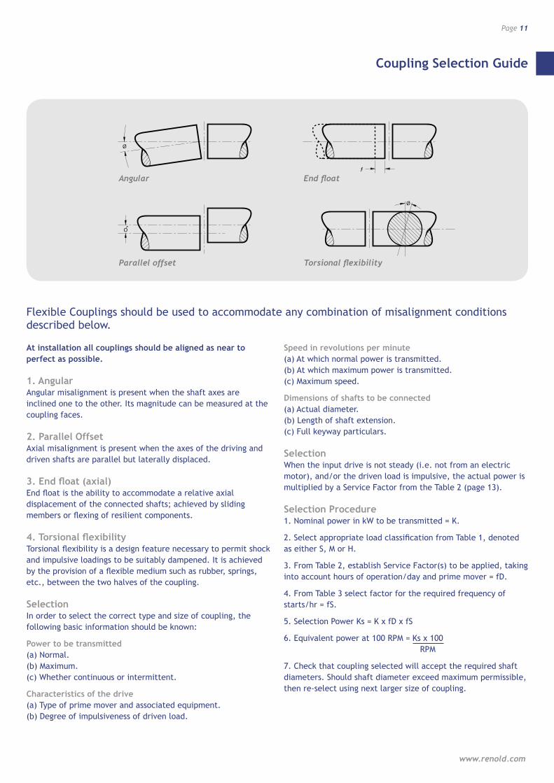
1. Angular Angular misalignment is present when the shaft axes are inclined one to the other. Its magnitude can be measured at the coupling faces.
2. Parallel Offset Axial misalignment is present when the axes of the driving and driven shafts are parallel but laterally displaced.
3. End float (axial) End float is the ability to accommodate a relative axial displacement of the connected shafts; achieved by sliding members or flexing of resilient components.
4. Torsional flexibility Torsional flexibility is a design feature necessary to permit shock and impulsive loadings to be suitably dampened. It is achieved by the provision of a flexible medium such as rubber, springs, etc., between the two halves of the coupling.
Selection In order to select the correct type and size of coupling, the following basic information should be known:
Power to be transmitted (a) Normal. (b) Maximum. (c) Whether continuous or intermittent.
Characteristics of the drive (a) Type of prime mover and associated equipment. (b) Degree of impulsiveness of driven load.
Speed in revolutions per minute (a) At which normal power is transmitted. (b) At which maximum power is transmitted. (c) Maximum speed.
Dimensions of shafts to be connected (a) Actual diameter. (b) Length of shaft extension. (c) Full keyway particulars.
Selection When the input drive is not steady (i.e. not from an electric motor), and/or the driven load is impulsive, the actual power is multiplied by a Service Factor from the Table 2 (page 13).
Selection Procedure 1. Nominal power in kW to be transmitted = K.
2. Select appropriate load classification from Table 1, denoted as either S, M or H.
3. From Table 2, establish Service Factor(s) to be applied, taking into account hours of operation/day and prime mover = fD.
4. From Table 3 select factor for the required frequency of starts/hr = fS.
5. Selection Power Ks = K x fD x fS
6. Equivalent power at 100 RPM = Ks x 100 RPM
7. Check that coupling selected will accept the required shaft diameters. Should shaft diameter exceed maximum permissible, then re-select using next larger size of coupling.
Flexible Couplings should be used to accommodate any combination of misalignment conditions described below.
Ø
ƒ
Ø
O
Angular
Ø
ƒ
Ø
O
Parallel offset
Ø
ƒ
Ø
O
End float
Ø
ƒ
Ø
O
Torsional flexibility
Load Classification by Application
Page 12
Resilient and Soft Start Couplings
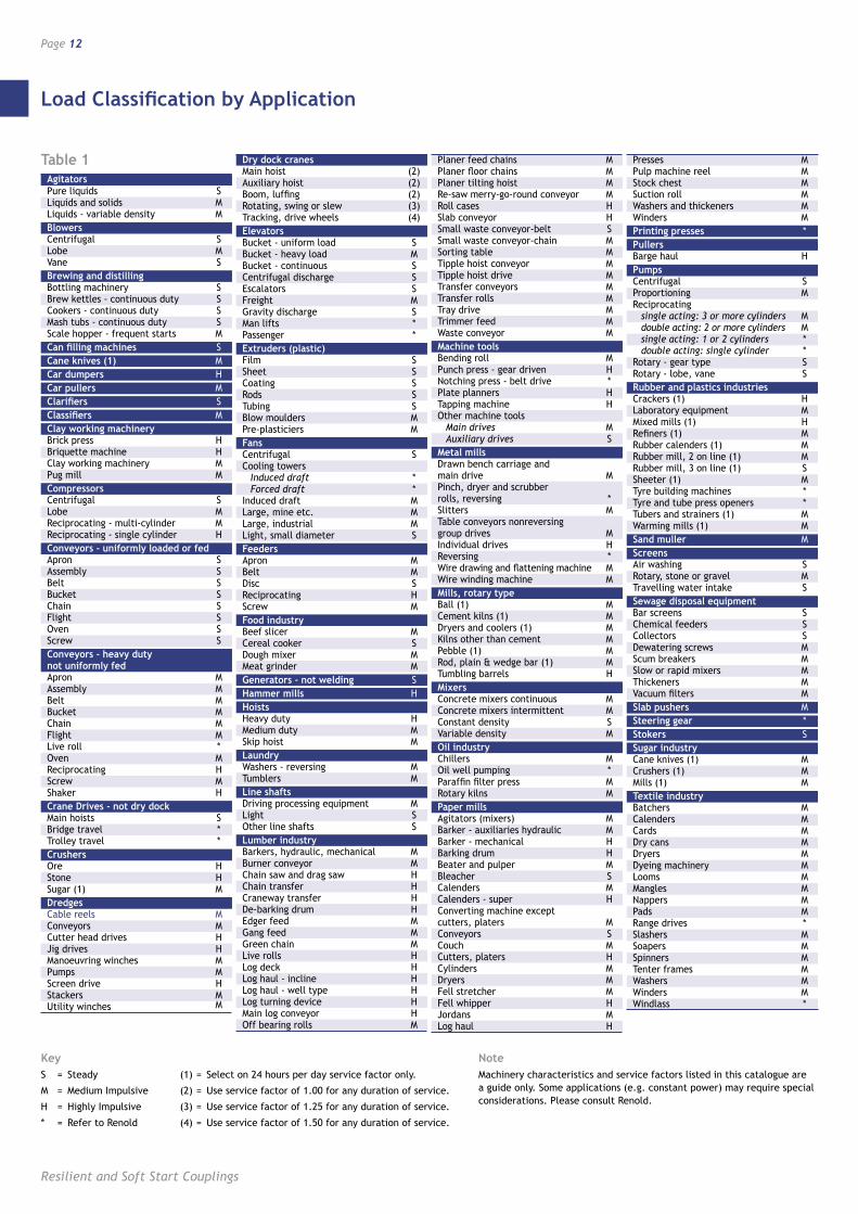
Agitators Pure liquids S Liquids and solids M Liquids - variable density MBlowers Centrifugal S Lobe M Vane SBrewing and distilling Bottling machinery S Brew kettles - continuous duty S Cookers - continuous duty S Mash tubs - continuous duty S Scale hopper - frequent starts MCan filling machines SCane knives (1) MCar dumpers HCar pullers MClarifiers SClassifiers MClay working machinery Brick press H Briquette machine H Clay working machinery M Pug mill MCompressors Centrifugal S Lobe M Reciprocating - multi-cylinder M Reciprocating - single cylinder HConveyors - uniformly loaded or fed Apron S Assembly S Belt S Bucket S Chain S Flight S Oven S Screw SConveyors - heavy duty not uniformly fed Apron M Assembly M Belt M Bucket M Chain M Flight M Live roll * Oven M Reciprocating H Screw M Shaker HCrane Drives - not dry dock Main hoists S Bridge travel * Trolley travel *Crushers Ore H Stone H Sugar (1) MDredges Cable reels M Conveyors M Cutter head drives H Jig drives H Manoeuvring winches M Pumps M Screen drive H Stackers M Utility winches M
Dry dock cranes Main hoist (2) Auxiliary hoist (2) Boom, luffing (2) Rotating, swing or slew (3) Tracking, drive wheels (4)Elevators Bucket - uniform load S Bucket - heavy load M Bucket - continuous S Centrifugal discharge S Escalators S Freight M Gravity discharge S Man lifts * Passenger *Extruders (plastic) Film S Sheet S Coating S Rods S Tubing S Blow moulders M Pre-plasticiers MFans Centrifugal S Cooling towers Induced draft * Forced draft * Induced draft M Large, mine etc. M Large, industrial M Light, small diameter SFeeders Apron M Belt M Disc S Reciprocating H Screw MFood industry Beef slicer M Cereal cooker S Dough mixer M Meat grinder MGenerators - not welding SHammer mills HHoists Heavy duty H Medium duty M Skip hoist MLaundry Washers - reversing M Tumblers MLine shafts Driving processing equipment M Light S Other line shafts SLumber industry Barkers, hydraulic, mechanical M Burner conveyor M Chain saw and drag saw H Chain transfer H Craneway transfer H De-barking drum H Edger feed M Gang feed M Green chain M Live rolls H Log deck H Log haul - incline H Log haul - well type H Log turning device H Main log conveyor H Off bearing rolls M
Planer feed chains M Planer floor chains M Planer tilting hoist M Re-saw merry-go-round conveyor M Roll cases H Slab conveyor H Small waste conveyor-belt S Small waste conveyor-chain M Sorting table M Tipple hoist conveyor M Tipple hoist drive M Transfer conveyors M Transfer rolls M Tray drive M Trimmer feed M Waste conveyor MMachine tools Bending roll M Punch press - gear driven H Notching press - belt drive * Plate planners H Tapping machine H Other machine tools Main drives M Auxiliary drives SMetal mills Drawn bench carriage and main drive M Pinch, dryer and scrubber rolls, reversing * Slitters M Table conveyors nonreversing group drives M Individual drives H Reversing * Wire drawing and flattening machine M Wire winding machine MMills, rotary type Ball (1) M Cement kilns (1) M Dryers and coolers (1) M Kilns other than cement M Pebble (1) M Rod, plain & wedge bar (1) M Tumbling barrels HMixers Concrete mixers continuous M Concrete mixers intermittent M Constant density S Variable density MOil industry Chillers M Oil well pumping * Paraffin filter press M Rotary kilns MPaper mills Agitators (mixers) M Barker - auxiliaries hydraulic M Barker - mechanical H Barking drum H Beater and pulper M Bleacher S Calenders M Calenders - super H Converting machine except cutters, platers M Conveyors S Couch M Cutters, platers H Cylinders M Dryers M Fell stretcher M Fell whipper H Jordans M Log haul H
Presses M Pulp machine reel M Stock chest M Suction roll M Washers and thickeners M Winders MPrinting presses *Pullers Barge haul HPumps Centrifugal S Proportioning M Reciprocating single acting: 3 or more cylinders M double acting: 2 or more cylinders M single acting: 1 or 2 cylinders * double acting: single cylinder * Rotary - gear type S Rotary - lobe, vane SRubber and plastics industries Crackers (1) H Laboratory equipment M Mixed mills (1) H Refiners (1) M Rubber calenders (1) M Rubber mill, 2 on line (1) M Rubber mill, 3 on line (1) S Sheeter (1) M Tyre building machines * Tyre and tube press openers * Tubers and strainers (1) M Warming mills (1) MSand muller MScreens Air washing S Rotary, stone or gravel M Travelling water intake SSewage disposal equipment Bar screens S Chemical feeders S Collectors S Dewatering screws M Scum breakers M Slow or rapid mixers M Thickeners M Vacuum filters MSlab pushers MSteering gear *Stokers SSugar industry Cane knives (1) M Crushers (1) M Mills (1) MTextile industry Batchers M Calenders M Cards M Dry cans M Dryers M Dyeing machinery M Looms M Mangles M Nappers M Pads M Range drives * Slashers M Soapers M Spinners M Tenter frames M Washers M Winders M Windlass *
Table 1
KeyS = Steady
M = Medium Impulsive
H = Highly Impulsive
* = Refer to Renold
(1) = Select on 24 hours per day service factor only.
(2) = Use service factor of 1.00 for any duration of service.
(3) = Use service factor of 1.25 for any duration of service.
(4) = Use service factor of 1.50 for any duration of service.
NoteMachinery characteristics and service factors listed in this catalogue are a guide only. Some applications (e.g. constant power) may require special considerations. Please consult Renold.
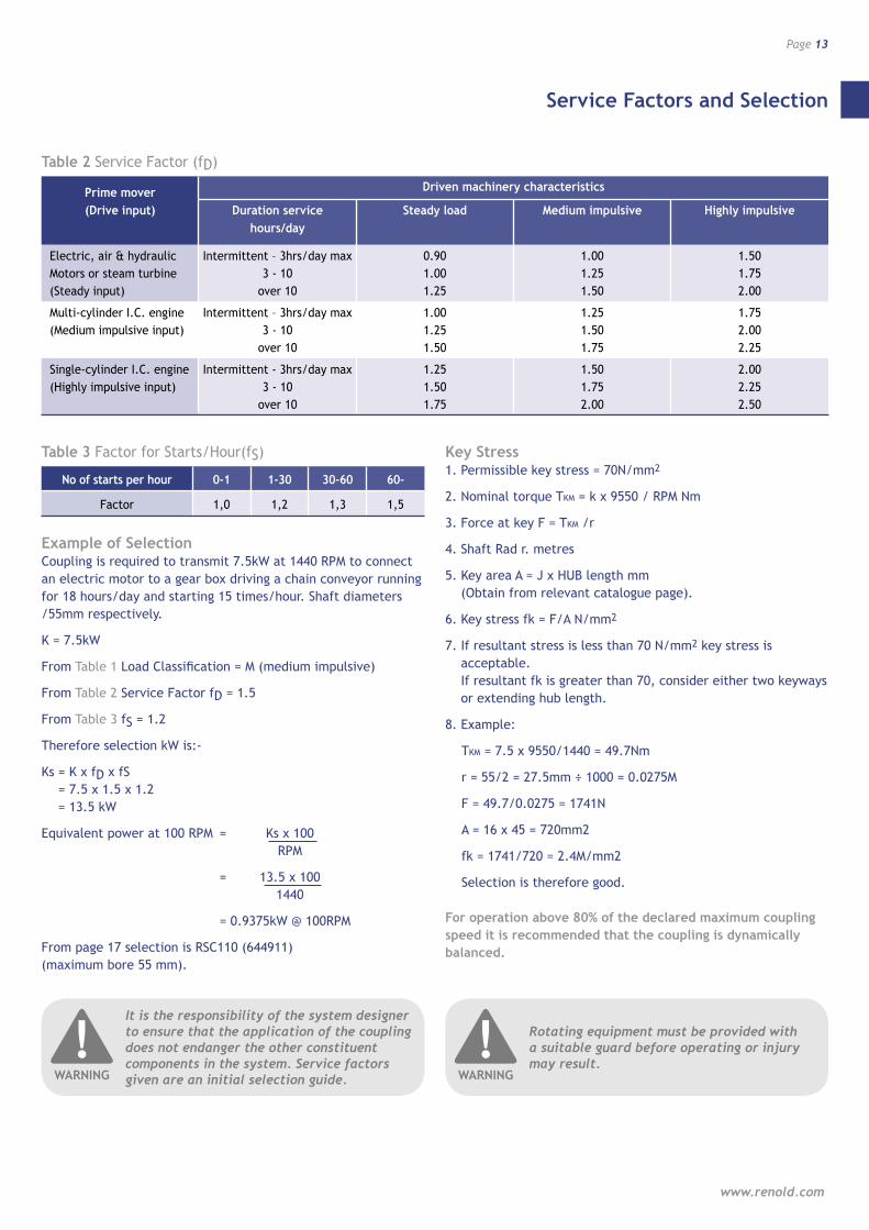
Example of Selection Coupling is required to transmit 7.5kW at 1440 RPM to connect an electric motor to a gear box driving a chain conveyor running for 18 hours/day and starting 15 times/hour. Shaft diameters /55mm respectively.
K = 7.5kW
From Table 1 Load Classification = M (medium impulsive)
From Table 2 Service Factor fD = 1.5
From Table 3 fS = 1.2
Therefore selection kW is:-
Ks = K x fD x fS = 7.5 x 1.5 x 1.2 = 13.5 kW
Equivalent power at 100 RPM = Ks x 100 RPM
= 13.5 x 100 1440
= 0.9375kW @ 100RPM
From page 17 selection is RSC110 (644911) (maximum bore 55 mm).
Key Stress 1. Permissible key stress = 70N/mm2
2. Nominal torque TKM = k x 9550 / RPM Nm
3. Force at key F = TKM /r
4. Shaft Rad r. metres
5. Key area A = J x HUB length mm (Obtain from relevant catalogue page).
6. Key stress fk = F/A N/mm2
7. If resultant stress is less than 70 N/mm2 key stress is acceptable. If resultant fk is greater than 70, consider either two keyways or extending hub length.
8. Example:
TKM = 7.5 x 9550/1440 = 49.7Nm
r = 55/2 = 27.5mm ÷ 1000 = 0.0275M
F = 49.7/0.0275 = 1741N
A = 16 x 45 = 720mm2
fk = 1741/720 = 2.4M/mm2
Selection is therefore good.
For operation above 80% of the declared maximum coupling speed it is recommended that the coupling is dynamically balanced.
Service Factors and Selection
www.renold.com
Page 13
Prime mover Driven machinery characteristics
(Drive input) Duration service Steady load Medium impulsive Highly impulsive hours/day
Electric, air & hydraulic Intermittent – 3hrs/day max 0.90 1.00 1.50 Motors or steam turbine 3 - 10 1.00 1.25 1.75 (Steady input) over 10 1.25 1.50 2.00
Multi-cylinder I.C. engine Intermittent – 3hrs/day max 1.00 1.25 1.75 (Medium impulsive input) 3 - 10 1.25 1.50 2.00 over 10 1.50 1.75 2.25
Single-cylinder I.C. engine Intermittent - 3hrs/day max 1.25 1.50 2.00 (Highly impulsive input) 3 - 10 1.50 1.75 2.25 over 10 1.75 2.00 2.50
Table 2 Service Factor (fD)
No of starts per hour 0-1 1-30 30-60 60-
Factor 1,0 1,2 1,3 1,5
Table 3 Factor for Starts/Hour(fS)
It is the responsibility of the system designer to ensure that the application of the coupling does not endanger the other constituent components in the system. Service factors given are an initial selection guide.
!WARNING
Rotating equipment must be provided with a suitable guard before operating or injury may result.
!WARNING
Key and Keyway Dimensions
Page 14
Resilient and Soft Start Couplings
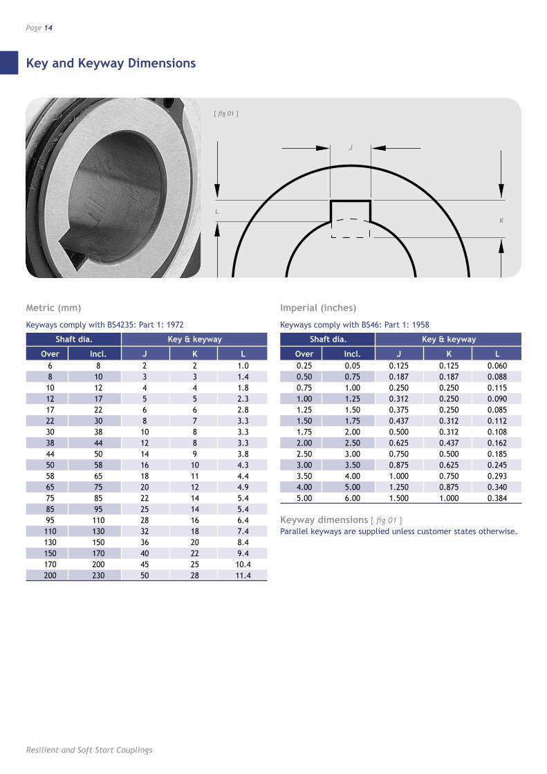
Metric (mm)
Keyways comply with BS4235: Part 1: 1972
Shaft dia. Key & keyway
Over Incl. J K L 6 8 2 2 1.0 8 10 3 3 1.4 10 12 4 4 1.8 12 17 5 5 2.3 17 22 6 6 2.8 22 30 8 7 3.3 30 38 10 8 3.3 38 44 12 8 3.3 44 50 14 9 3.8 50 58 16 10 4.3 58 65 18 11 4.4 65 75 20 12 4.9 75 85 22 14 5.4 85 95 25 14 5.4 95 110 28 16 6.4 110 130 32 18 7.4 130 150 36 20 8.4 150 170 40 22 9.4 170 200 45 25 10.4 200 230 50 28 11.4
Imperial (inches)
Keyways comply with BS46: Part 1: 1958
Shaft dia. Key & keyway
Over Incl. J K L 0.25 0.05 0.125 0.125 0.060 0.50 0.75 0.187 0.187 0.088 0.75 1.00 0.250 0.250 0.115 1.00 1.25 0.312 0.250 0.090 1.25 1.50 0.375 0.250 0.085 1.50 1.75 0.437 0.312 0.112 1.75 2.00 0.500 0.312 0.108 2.00 2.50 0.625 0.437 0.162 2.50 3.00 0.750 0.500 0.185 3.00 3.50 0.875 0.625 0.245 3.50 4.00 1.000 0.750 0.293 4.00 5.00 1.250 0.875 0.340 5.00 6.00 1.500 1.000 0.384
Keyway dimensions [ fig 01 ] Parallel keyways are supplied unless customer states otherwise.
L
J
[ fig 01 ]
K
L
J
pag
e 8
A/W
’s
K
Taper Bushes
www.renold.com
Page 15
K
L
J
page 8 A/W’s
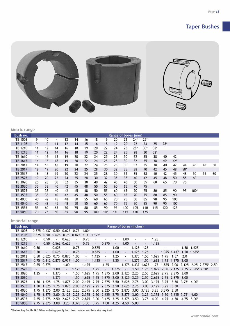
Metric range Bush no. Range of bores (mm) TB 1008 9 10 - 12 14 16 18 19 20 22 24* 25* TB 1108 9 10 11 12 14 15 16 18 19 20 22 24 25 28* TB 1210 11 12 14 16 18 19 20 22 24 25 28* 30* 32* TB 1215 11 12 14 16 18 19 20 22 24 25 28 30 32* TB 1610 14 16 18 19 20 22 24 25 28 30 32 35 38 40 42 TB 1615 14 16 18 19 20 22 24 25 28 30 32 35 38 40* 42* TB 2012 14 16 18 19 20 22 24 25 28 30 32 35 38 40 42 44 45 48 50 TB 2017 18 19 20 22 24 25 28 30 32 35 38 40 42 45 48 50* TB 2517 16 18 19 20 22 24 25 28 30 32 35 38 40 42 45 48 50 55 60 TB 2525 19 20 22 24 25 28 30 32 35 38 40 42 45 48 50 55 60 TB 3020 25 28 30 32 35 38 40 42 45 48 50 55 60 65 70 75 TB 3030 35 38 40 42 45 48 50 55 60 65 70 75 TB 3525 35 38 40 42 45 48 50 55 60 65 70 75 80 85 90 95 100* TB 3535 35 38 40 42 45 48 50 55 60 65 70 75 80 85 90 TB 4030 40 42 45 48 50 55 60 65 70 75 80 85 90 95 100 TB 4040 40 42 45 48 50 55 60 65 70 75 80 85 90 95 100 TB 4535 55 60 65 70 75 80 85 90 95 100 105 110 115 120 125 TB 5050 70 75 80 85 90 95 100 105 110 115 120 125
Imperial range Bush no. Range of bores (inches) TB 1008 0.375 0.437 0.50 0.625 0.75 1.00* TB 1108 0.375 0.50 0.625 0.75 0.875 1.00 1.125* TB 1210 - 0.50 - 0.625 - 0.75 - - - 1.00 - - 1.25 TB 1215 - 0.50 0.562 0.625 - 0.75 - 0.875 - 1.00 - - 1.125 TB 1610 0.50 - 0.625 - 0.75 - 0.875 - 1.00 - 1.125 1.25 - - - 1.50 1.625 TB 1615 0.50 - 0.625 - 0.75 - 0.875 - 1.00 - 1.125 1.25 - 1.375 1.437 1.50 1.625* TB 2012 0.50 0.625 0.75 0.875 1.00 - 1.125 - 1.25 - 1.375 1.50 1.625 1.75 1.87 2.0 TB 2017 0.75 0.812 0.875 0.937 1.00 - 1.125 - 1.25 - 1.375 1.50 1.625 1.75 1.875 2.00 TB 2517 0.75 0.875 - 1.00 - 1.125 - 1.25 - 1.375 1.437 1.625 1.75 1.875 2.00 2.125 2.25 2.375* 2.50 TB 2525 - - 1.00 - 1.125 - 1.25 - 1.375 - 1.50 1.75 1.875 2.00 2.125 2.25 2.375* 2.50* TB 3020 1.25 - 1.375 - 1.50 1.625 1.75 1.875 2.00 2.125 2.25 2.50 2.625 2.75 2.875 3.00 TB 3030 - - 1.375 - 1.50 1.625 1.75 1.875 2.00 2.125 2.25 2.50 2.625 2.75 2.875 3.00 TB 3525 1.50 1.625 1.75 1.875 2.00 2.125 2.25 2.375 2.50 2.625 2.75 3.00 3.125 3.25 3.50 3.75* 4.00* TB 3535 1.50 1.625 1.75 1.875 2.00 2.125 2.25 2.375 2.50 2.625 2.75 3.00 3.125 3.25 3.50 TB 4030 1.75 1.875 2.00 2.125 2.25 2.375 2.50 2.625 2.75 2.875 3.00 3.125 3.25 3.375 3.50 TB 4040 1.75 1.875 2.00 2.125 2.25 2.375 2.50 2.625 2.75 2.875 3.00 3.25 3.375 3.50 3.625 3.75* 4.00 TB 4535 2.25 2.375 2.50 2.625 2.75 2.875 3.00 3.125 3.25 3.375 3.50 3.75 4.00 4.25 4.50 4.75 5.00* TB 5050 2.75 2.875 3.00 3.25 3.375 3.50 3.75 4.00 4.25 4.50 5.00
*Shallow key Depth. N.B.When ordering specify both bush number and bore size required.
Spiderflex
Page 16
Resilient and Soft Start Couplings
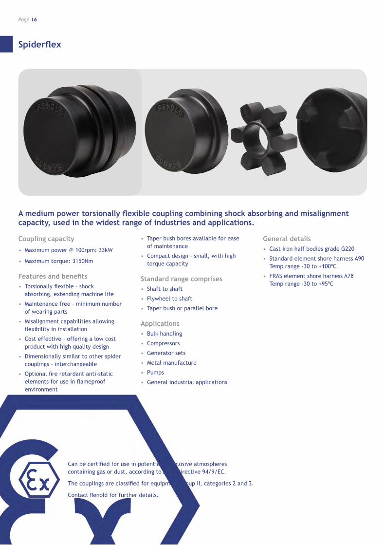
A medium power torsionally flexible coupling combining shock absorbing and misalignment capacity, used in the widest range of industries and applications.
Coupling capacity
• Maximum power @ 100rpm: 33kW
• Maximum torque: 3150Nm
Features and benefits• Torsionally flexible – shock
absorbing, extending machine life
• Maintenance free – minimum number of wearing parts
• Misalignment capabilities allowing flexibility in installation
• Cost effective – offering a low cost product with high quality design
• Dimensionally similar to other spider couplings – interchangeable
• Optional fire retardant anti-static elements for use in flameproof environment
• Taper bush bores available for ease of maintenance
• Compact design – small, with high torque capacity
Standard range comprises• Shaft to shaft
• Flywheel to shaft
• Taper bush or parallel bore
Applications• Bulk handling
• Compressors
• Generator sets
• Metal manufacture
• Pumps
• General industrial applications
General details• Cast iron half bodies grade G220
• Standard element shore harness A90 Temp range -30 to +100ºC
• FRAS element shore harness A78 Temp range -30 to +95ºC
Can be certified for use in potentially explosive atmospheres containing gas or dust, according to ATEX directive 94/9/EC.
The couplings are classified for equipment group II, categories 2 and 3.
Contact Renold for further details.
Spiderflex
www.renold.com
Page 17
L
G
H1
C1
BD BD E
H2
C2
BD
H2
C2F
H1
C1
BD BD
C2
H1
BD
C2
H1
F
L
G
E
Assembled length
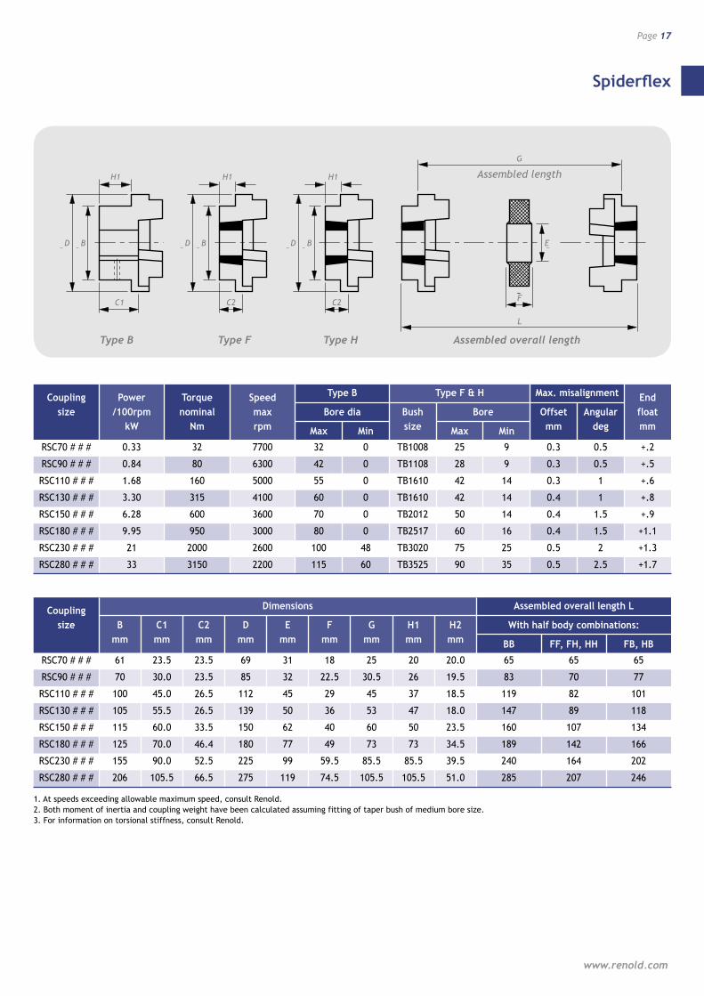
Coupling Dimensions Assembled overall length L
size B C1 C2 D E F G H1 H2 With half body combinations: mm mm mm mm mm mm mm mm mm BB FF, FH, HH FB, HB
RSC70 # # # 61 23.5 23.5 69 31 18 25 20 20.0 65 65 65
RSC90 # # # 70 30.0 23.5 85 32 22.5 30.5 26 19.5 83 70 77
RSC110 # # # 100 45.0 26.5 112 45 29 45 37 18.5 119 82 101
RSC130 # # # 105 55.5 26.5 139 50 36 53 47 18.0 147 89 118
RSC150 # # # 115 60.0 33.5 150 62 40 60 50 23.5 160 107 134
RSC180 # # # 125 70.0 46.4 180 77 49 73 73 34.5 189 142 166
RSC230 # # # 155 90.0 52.5 225 99 59.5 85.5 85.5 39.5 240 164 202
RSC280 # # # 206 105.5 66.5 275 119 74.5 105.5 105.5 51.0 285 207 246
1. At speeds exceeding allowable maximum speed, consult Renold.2. Both moment of inertia and coupling weight have been calculated assuming fitting of taper bush of medium bore size.3. For information on torsional stiffness, consult Renold.
Coupling Power Torque Speed Type B Type F & H Max. misalignment End size /100rpm nominal max Bore dia Bush Bore Offset Angular float kW Nm rpm Max Min size Max Min mm deg mm
RSC70 # # # 0.33 32 7700 32 0 TB1008 25 9 0.3 0.5 +.2
RSC90 # # # 0.84 80 6300 42 0 TB1108 28 9 0.3 0.5 +.5
RSC110 # # # 1.68 160 5000 55 0 TB1610 42 14 0.3 1 +.6
RSC130 # # # 3.30 315 4100 60 0 TB1610 42 14 0.4 1 +.8
RSC150 # # # 6.28 600 3600 70 0 TB2012 50 14 0.4 1.5 +.9
RSC180 # # # 9.95 950 3000 80 0 TB2517 60 16 0.4 1.5 +1.1
RSC230 # # # 21 2000 2600 100 48 TB3020 75 25 0.5 2 +1.3
RSC280 # # # 33 3150 2200 115 60 TB3525 90 35 0.5 2.5 +1.7
Type B Type HType F Assembled overall length
Spiderflex
Page 18
Resilient and Soft Start Couplings
Coupling Coupling Coupling Inertia WR2
size Mass Type B Type F&H
Kg KG m2 KG m2
RSC70 1.00 0.00078 0.00085
RSC90 1.17 0.00108 0.00115
RSC110 5.00 0.00344 0.00400
RSC130 5.46 0.00850 0.00780
RSC150 7.11 0.02112 0.01810
RSC180 16.60 0.04820 0.04340
RSC230 26.00 0.14052 0.12068
RSC280 50.00 0.54790 0.44653
Spider Product Half body Product Half body Product Half body Product flexible number unbored number taper bored number taper bored number element Type B Type F Type H
RSC70 EL 644907/2 RSC70 B 644907/1 RSC70 F 644907/177 RSC70 H 644907/188
RSC90 EL 644909/2 RSC90 B 644909/1 RSC90 F 644909/177 RSC90 H 644909/188
RSC110 EL 644911/2 RSC110 B 644911/1 RSC110 F 644911/177 RSC110 H 644911/188
RSC130 EL 644913/2 RSC130 B 644913/1 RSC130 F 644913/177 RSC130 H 644913/188
RSC150 EL 644915/2 RSC150 B 644915/1 RSC150 F 644915/177 RSC150 H 644915/188
RSC180 EL 644918/2 RSC180 B 644918/1 RSC180 F 644918/177 RSC180 H 644918/188
RSC230 EL 644923/2 RSC230 B 644923/1 RSC230 F 644923/177 RSC230 H 644923/188
RSC280 EL 644928/2 RSC280 B 644928/1 RSC280 F 644928/177 RSC280 H 644928/188
Component Spares
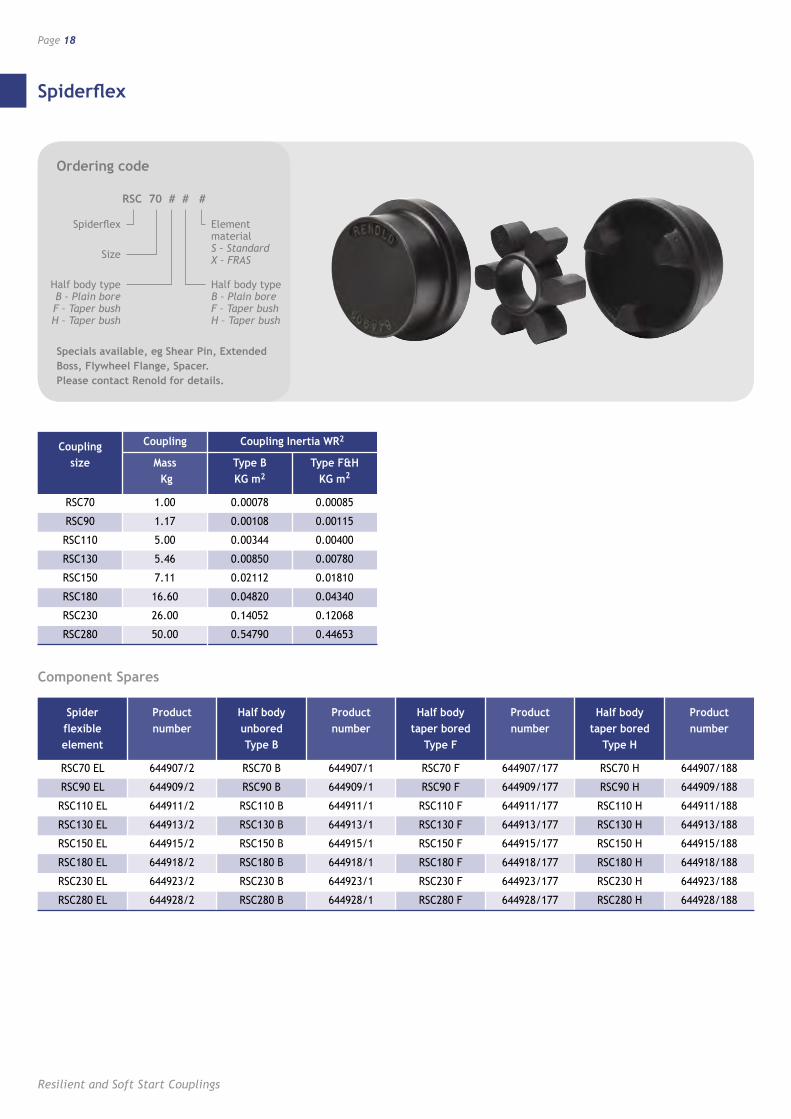
Ordering code
RSC 70 # # #
Spiderflex
Size
Element material S – Standard X – FRAS
Half body type B – Plain bore F – Taper bush
H – Taper bush
Half body type B – Plain bore F – Taper bush H – Taper bush
Specials available, eg Shear Pin, Extended Boss, Flywheel Flange, Spacer. Please contact Renold for details.
Spider
www.renold.com
Page 19
C C
AD B
FF
C C
AD B
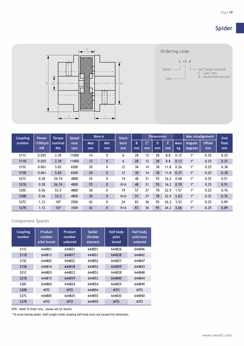
Coupling Power Torque Speed Bore A Stock Dimensions Max misalignment End number /100rpm nominal max Max Min bore B C* D F Mass Angular Offset float kW Nm rpm mm mm mm mm mm mm mm kg degrees mm mm
S11C 0.025 2.39 11000 14 0 6 28 12 28 8.8 0.12 1º 0.25 0.25
S11B 0.025 2.39 11000 12 0 6 28 12 28 8.8 0.13 1º 0.25 0.25
S15C 0.061 5.83 6500 20 0 12 38 14 38 11.8 0.26 1º 0.25 0.38
S15B 0.061 5.83 6500 20 0 12 38 14 38 11.8 0.27 1º 0.25 0.38
S21C 0.28 26.74 4800 25 0 14 48 21 55 16.2 0.68 1º 0.25 0.51
S21B 0.28 26.74 4800 25 0 N/A 48 21 55 16.2 0.70 1º 0.25 0.51
S30C 0.56 53.5 4800 30 0 19 57 27 78 22.9 1.57 1º 0.25 0.76
S30B 0.56 53.5 4800 30 0 N/A 57 27 78 22.9 1.63 1º 0.25 0.76
S37C 1.12 107 3500 42 0 24 83 36 95 26.2 3.53 1º 0.25 0.89
S37B 1.12 107 3500 42 0 N/A 83 36 95 26.2 3.66 1º 0.25 0.89
Coupling Product Product Spider Half body Half body number number number flexible pilot solid boss pilot bored unbored element bored unbored
S11C 644801 644821 644851 644826 644846
S11B 644813 644817 644851 644838 644842
S15C 644802 644822 644852 644827 644847
S15B 644814 644818 644852 644839 644843
S21C 644803 644823 644853 644828 644848
S21B 644815 644819 644853 644840 644844
S30C 644804 644824 644854 644829 644849
S30B MTO MTO 644854 MTO MTO
S37C 644805 644825 644855 644830 644850
S37B MTO MTO 644855 MTO MTO
MTO - Made To Order only - please ask for details.
* To avoid fouling spider, shaft length inside coupling half-body must not exceed this dimension.
Component Spares
Ordering code
S 15 #
Spider
Size
Half body material C – Cast ironB – Aluminium bronze
Pinflex
Page 20
Resilient and Soft Start Couplings
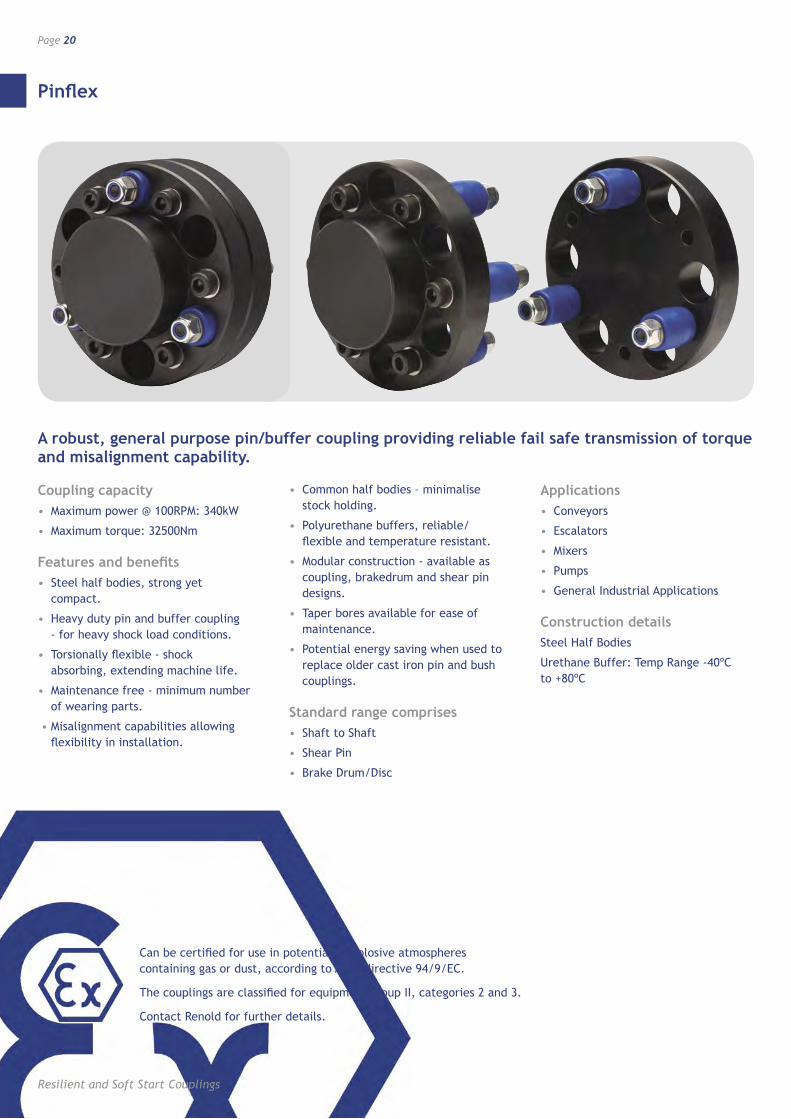
A robust, general purpose pin/buffer coupling providing reliable fail safe transmission of torque and misalignment capability.
Coupling capacity• Maximum power @ 100RPM: 340kW
• Maximum torque: 32500Nm
Features and benefits• Steel half bodies, strong yet
compact.
• Heavy duty pin and buffer coupling - for heavy shock load conditions.
• Torsionally flexible - shock absorbing, extending machine life.
• Maintenance free - minimum number of wearing parts.
• Misalignment capabilities allowing flexibility in installation.
• Common half bodies – minimalise stock holding.
• Polyurethane buffers, reliable/flexible and temperature resistant.
• Modular construction - available as coupling, brakedrum and shear pin designs.
• Taper bores available for ease of maintenance.
• Potential energy saving when used to replace older cast iron pin and bush couplings.
Standard range comprises• Shaft to Shaft
• Shear Pin
• Brake Drum/Disc
Applications• Conveyors
• Escalators
• Mixers
• Pumps
• General Industrial Applications
Construction detailsSteel Half Bodies
Urethane Buffer: Temp Range -40ºC to +80ºC
Can be certified for use in potentially explosive atmospheres containing gas or dust, according to ATEX directive 94/9/EC.
The couplings are classified for equipment group II, categories 2 and 3.
Contact Renold for further details.
Pinflex
www.renold.com
Page 21
D
E
B
C2
F
C1 C2C1
BD
C2
FE
C2
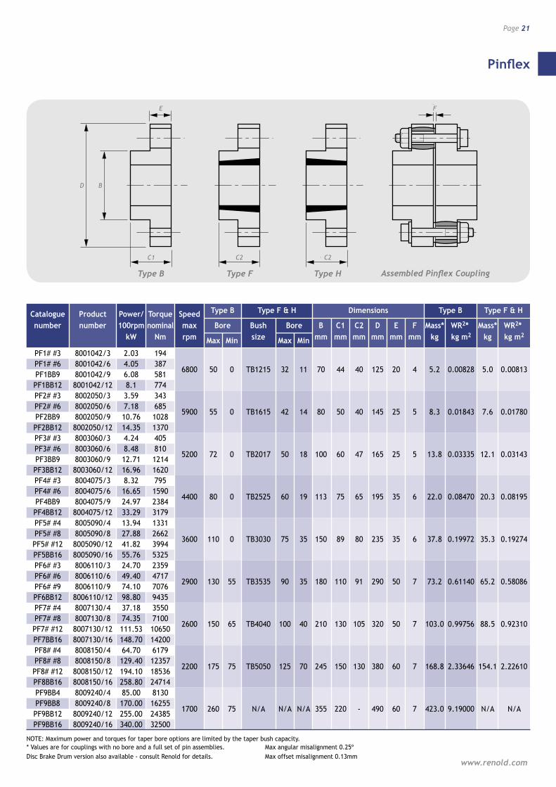
Catalogue Product Power/ Torque Speed Type B Type F & H Dimensions Type B Type F & H
number number 100rpm nominal max Bore Bush Bore B C1 C2 D E F Mass* WR2* Mass* WR2* kW Nm rpm Max Min size Max Min mm mm mm mm mm mm kg kg m2 kg kg m2
PF1# #3 8001042/3 2.03 194 PF1# #6 8001042/6 4.05 387
6800 50 0 TB1215 32 11 70 44 40 125 20 4 5.2 0.00828 5.0 0.00813 PF1BB9 8001042/9 6.08 581 PF1BB12 8001042/12 8.1 774 PF2# #3 8002050/3 3.59 343 PF2# #6 8002050/6 7.18 685
5900 55 0 TB1615 42 14 80 50 40 145 25 5 8.3 0.01843 7.6 0.01780 PF2BB9 8002050/9 10.76 1028 PF2BB12 8002050/12 14.35 1370 PF3# #3 8003060/3 4.24 405 PF3# #6 8003060/6 8.48 810
5200 72 0 TB2017 50 18 100 60 47 165 25 5 13.8 0.03335 12.1 0.03143 PF3BB9 8003060/9 12.71 1214 PF3BB12 8003060/12 16.96 1620 PF4# #3 8004075/3 8.32 795 PF4# #6 8004075/6 16.65 1590
4400 80 0 TB2525 60 19 113 75 65 195 35 6 22.0 0.08470 20.3 0.08195 PF4BB9 8004075/9 24.97 2384 PF4BB12 8004075/12 33.29 3179 PF5# #4 8005090/4 13.94 1331 PF5# #8 8005090/8 27.88 2662
3600 110 0 TB3030 75 35 150 89 80 235 35 6 37.8 0.19972 35.3 0.19274 PF5# #12 8005090/12 41.82 3994 PF5BB16 8005090/16 55.76 5325 PF6# #3 8006110/3 24.70 2359 PF6# #6 8006110/6 49.40 4717
2900 130 55 TB3535 90 35 180 110 91 290 50 7 73.2 0.61140 65.2 0.58086 PF6# #9 8006110/9 74.10 7076 PF6BB12 8006110/12 98.80 9435 PF7# #4 8007130/4 37.18 3550 PF7# #8 8007130/8 74.35 7100
2600 150 65 TB4040 100 40 210 130 105 320 50 7 103.0 0.99756 88.5 0.92310 PF7# #12 8007130/12 111.53 10650 PF7BB16 8007130/16 148.70 14200 PF8# #4 8008150/4 64.70 6179 PF8# #8 8008150/8 129.40 12357
2200 175 75 TB5050 125 70 245 150 130 380 60 7 168.8 2.33646 154.1 2.22610 PF8# #12 8008150/12 194.10 18536 PF8BB16 8008150/16 258.80 24714 PF9BB4 8009240/4 85.00 8130 PF9BB8 8009240/8 170.00 16255
1700 260 75 N/A N/A N/A 355 220 - 490 60 7 423.0 9.19000 N/A N/A PF9BB12 8009240/12 255.00 24385 PF9BB16 8009240/16 340.00 32500
NOTE: Maximum power and torques for taper bore options are limited by the taper bush capacity. * Values are for couplings with no bore and a full set of pin assemblies. Max angular misalignment 0.25º Disc Brake Drum version also available - consult Renold for details. Max offset misalignment 0.13mm
Assembled Pinflex CouplingType HType FType B
Component Spares
Pinflex
Page 22
Resilient and Soft Start Couplings
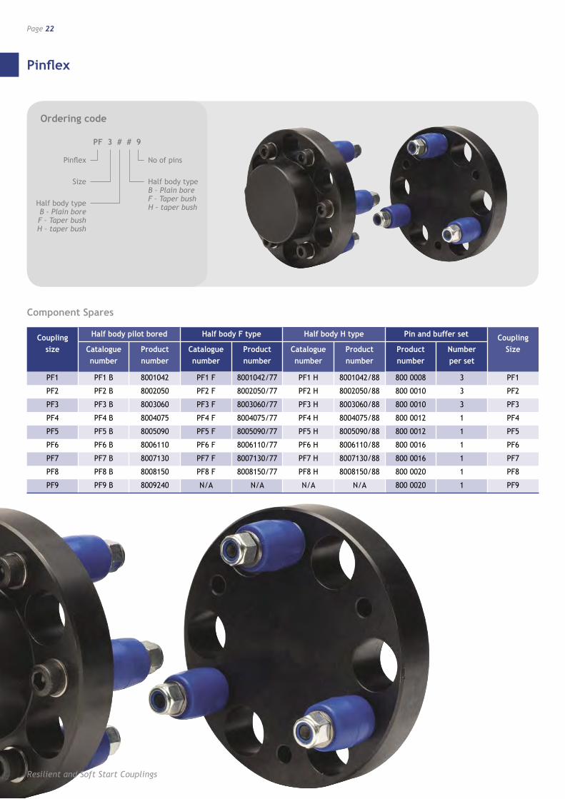
Coupling Half body pilot bored Half body F type Half body H type Pin and buffer set Coupling size Catalogue Product Catalogue Product Catalogue Product Product Number Size
number number number number number number number per set PF1 PF1 B 8001042 PF1 F 8001042/77 PF1 H 8001042/88 800 0008 3 PF1
PF2 PF2 B 8002050 PF2 F 8002050/77 PF2 H 8002050/88 800 0010 3 PF2
PF3 PF3 B 8003060 PF3 F 8003060/77 PF3 H 8003060/88 800 0010 3 PF3
PF4 PF4 B 8004075 PF4 F 8004075/77 PF4 H 8004075/88 800 0012 1 PF4
PF5 PF5 B 8005090 PF5 F 8005090/77 PF5 H 8005090/88 800 0012 1 PF5
PF6 PF6 B 8006110 PF6 F 8006110/77 PF6 H 8006110/88 800 0016 1 PF6
PF7 PF7 B 8007130 PF7 F 8007130/77 PF7 H 8007130/88 800 0016 1 PF7
PF8 PF8 B 8008150 PF8 F 8008150/77 PF8 H 8008150/88 800 0020 1 PF8
PF9 PF9 B 8009240 N/A N/A N/A N/A 800 0020 1 PF9
Ordering code
PF 3 # # 9
Pinflex
Size
No of pins
Half body type B – Plain bore F – Taper bush H – taper bush
Half body type B – Plain bore F – Taper bush H – taper bush
Pinflex Brakedrum Coupling
www.renold.com
Page 23
A1D B1 E
G H
F
C1 C2
A2 B2B1D
C2
F
G
C2
H
A1 B2 EA2
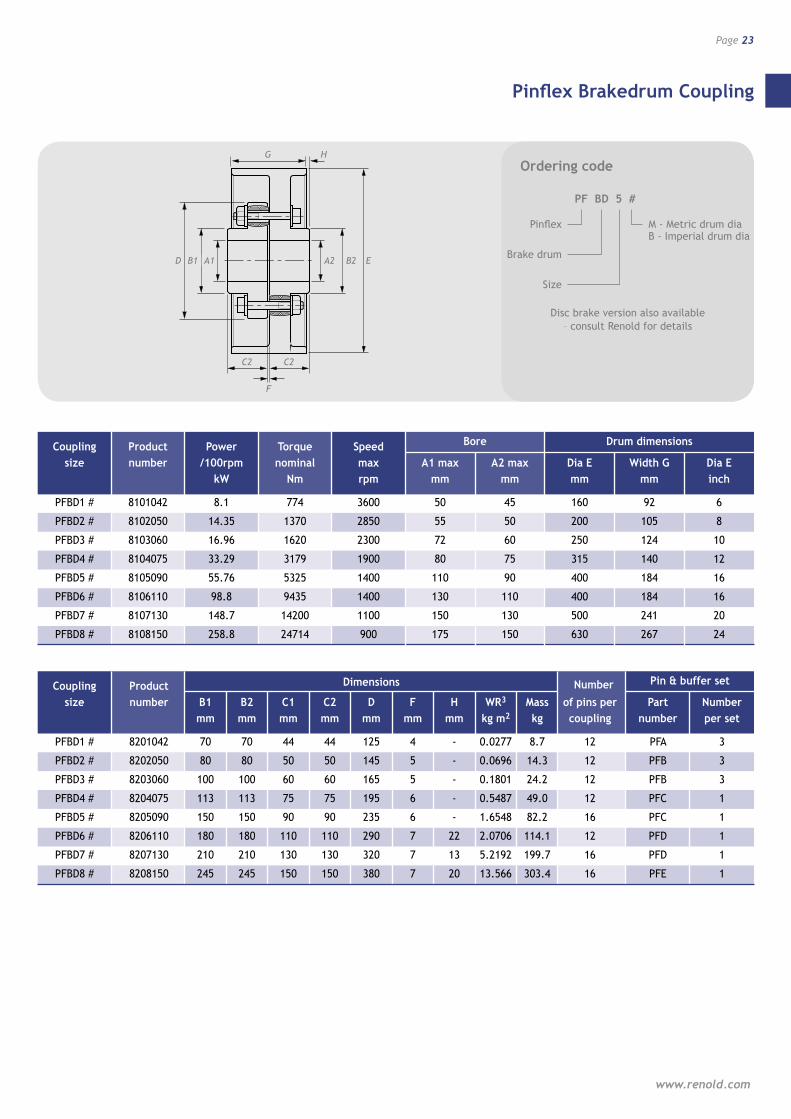
Coupling Product Power Torque Speed Bore Drum dimensions
size number /100rpm nominal max A1 max A2 max Dia E Width G Dia E kW Nm rpm mm mm mm mm inch
PFBD1 # 8101042 8.1 774 3600 50 45 160 92 6
PFBD2 # 8102050 14.35 1370 2850 55 50 200 105 8
PFBD3 # 8103060 16.96 1620 2300 72 60 250 124 10
PFBD4 # 8104075 33.29 3179 1900 80 75 315 140 12
PFBD5 # 8105090 55.76 5325 1400 110 90 400 184 16
PFBD6 # 8106110 98.8 9435 1400 130 110 400 184 16
PFBD7 # 8107130 148.7 14200 1100 150 130 500 241 20
PFBD8 # 8108150 258.8 24714 900 175 150 630 267 24
Coupling Product Dimensions Number Pin & buffer set
size number B1 B2 C1 C2 D F H WR3 Mass of pins per Part Number mm mm mm mm mm mm mm kg m2 kg coupling number per set
PFBD1 # 8201042 70 70 44 44 125 4 - 0.0277 8.7 12 PFA 3
PFBD2 # 8202050 80 80 50 50 145 5 - 0.0696 14.3 12 PFB 3
PFBD3 # 8203060 100 100 60 60 165 5 - 0.1801 24.2 12 PFB 3
PFBD4 # 8204075 113 113 75 75 195 6 - 0.5487 49.0 12 PFC 1
PFBD5 # 8205090 150 150 90 90 235 6 - 1.6548 82.2 16 PFC 1
PFBD6 # 8206110 180 180 110 110 290 7 22 2.0706 114.1 12 PFD 1
PFBD7 # 8207130 210 210 130 130 320 7 13 5.2192 199.7 16 PFD 1
PFBD8 # 8208150 245 245 150 150 380 7 20 13.566 303.4 16 PFE 1
Ordering code
PF BD 5 #
Pinflex
Brake drum
M - Metric drum dia B - Imperial drum dia
Size
Disc brake version also available – consult Renold for details
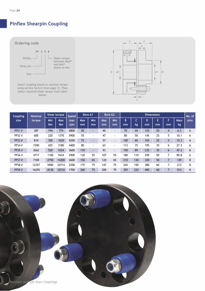
Pinflex Shearpin Coupling
Page 24
Resilient and Soft Start Couplings
Ordering code
PF S 5 #
Pinflex
Shear pin
Shear torque between MaxM and MinM
shown in Nm
Size
Coupling Nominal Shear torque Speed Bore A1 Bore A2 Dimensions No. of size torque Min Max max Max Min Max Min B C D E F Mass pins Nm Nm rpm mm mm mm mm mm kg mm mm mm kg
PFS1 # 387 194 774 6800 50 - 40 - 70 44 125 20 4 6.3 6
PFS2 # 685 220 1370 5900 55 - 47 - 80 50 145 25 5 10.1 6
PFS3 # 810 350 1620 5200 72 - 57 - 100 60 165 25 5 15.3 6
PFS4 # 1590 425 3180 4400 80 - 63 - 113 75 195 35 6 27.3 6
PFS5 # 2662 520 5324 3600 110 - 93 - 150 89 235 35 6 47.3 8
PFS6 # 4717 1100 9434 2900 130 55 107 55 180 110 290 50 7 89.8 6
PFS7 # 7100 2750 14200 2600 150 65 120 65 210 130 320 50 7 129 8
PFS8 # 12357 5900 24714 2200 175 75 147 75 245 150 380 60 7 212 8
PFS9 # 16255 8130 32510 1700 260 75 200 75 355 220 490 60 7 513 8
D
F
C C
A2 BA1
E
Select coupling based on nominal torque using service factors from page 13. Then select required shear torque from table
below.
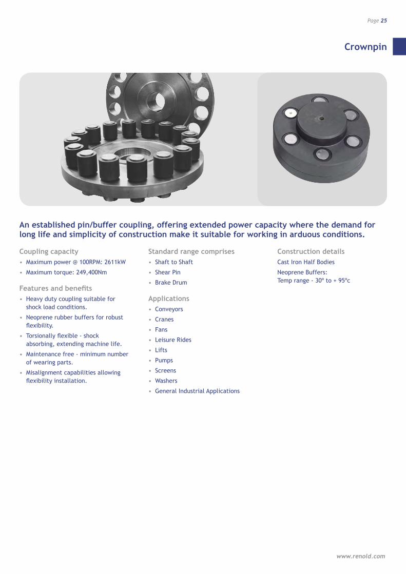
Crownpin
www.renold.com
Page 25
An established pin/buffer coupling, offering extended power capacity where the demand for long life and simplicity of construction make it suitable for working in arduous conditions.
Coupling capacity• Maximum power @ 100RPM: 2611kW
• Maximum torque: 249,400Nm
Features and benefits• Heavy duty coupling suitable for
shock load conditions.
• Neoprene rubber buffers for robust flexibility.
• Torsionally flexible - shock absorbing, extending machine life.
• Maintenance free - minimum number of wearing parts.
• Misalignment capabilities allowing flexibility installation.
Standard range comprises• Shaft to Shaft
• Shear Pin
• Brake Drum
Applications• Conveyors
• Cranes
• Fans
• Leisure Rides
• Lifts
• Pumps
• Screens
• Washers
• General Industrial Applications
Construction detailsCast Iron Half Bodies
Neoprene Buffers: Temp range - 30º to + 95ºc
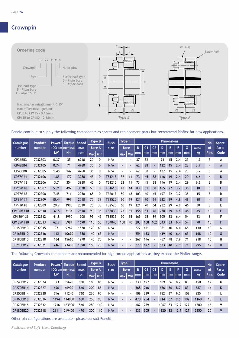
Crownpin
Page 26
Resilient and Soft Start Couplings
Ordering code
CP 77 # # 8
Crownpin
Size
No of pins
Pin half type B – Plain bore F – Taper bush
AD B
C1C1
E
F
GPIN HALF
BUFFER HALF
C2C2
BD
C1
G
C1
A
E
F
C2 C2
Pin half
Buffer half
Buffer half type B – Plain bore F – Taper bush
Max angular misalignment 0.15º Max offset misalignment:- CP36 to CP135 - 0.13mm CP150 to CP480 - 0.18mm
Other pin configurations are available - please consult Renold.
Catalogue Product Power/ Torque Speed Type B Bush Type F Dimensions No Spare number number 100rpm nominal max Bore A size Bore B C1 C2 D E F G Mass of Parts kW Nm rpm Max Min Max Min mm mm mm mm mm mm mm kg Pins Code
CP36BB3 7032303 0.37 35 6210 20 0 N/A - - 37 32 - 94 15 2.4 23 1.9 3 A
CP48BB4 7032105 0.74 71 4760 35 0 N/A - - 62 38 - 122 15 2.4 23 3.7 4 A
CP48BB8 7032305 1.48 142 4760 35 0 N/A - - 62 38 - 122 15 2.4 23 3.7 8 A
CP57# #4 7032106 1.85 177 3980 45 0 TB1215 32 11 73 45 38 146 19 2.4 29 6.6 4 B
CP57# #8 7032306 3.7 354 3980 45 0 TB1215 32 11 73 45 38 146 19 2.4 29 6.6 8 B
CP65# #8 7032307 5.21 497 3520 50 0 TB1615 42 14 83 51 38 165 22 3.2 35 10 8 C
CP77# #8 7032308 7.45 711 2950 65 0 TB2017 50 18 103 60 45 197 22 3.2 35 15 8 D
CP91# #4 7032309 10.44 997 2510 75 38 TB2525 60 19 121 70 64 232 29 4.8 46 30 4 E
CP91# #8 7032309 20.9 1995 2510 75 38 TB2525 60 19 121 70 64 232 29 4.8 46 30 8 E
CP106# #10 7032310 32.8 3134 2510 90 38 TB3030 75 35 156 83 76 270 29 4.8 46 45 10 E
CP120# #8 7032312 41.8 3990 1900 95 45 TB3535 90 35 165 95 89 305 33 6.4 54 63 8 F
CP135# #10 7032313 62.7 5984 1690 115 50 TB4040 100 40 203 108 102 343 33 6.4 54 90 10 F
CP150BB10 7032315 97 9262 1520 120 60 N/A - - 222 121 - 381 40 6.4 65 130 10 G
CP165BB10 7032316 112 10690 1380 140 65 N/A - - 254 133 - 419 40 6.4 65 168 10 G
CP180BB10 7032318 164 15660 1270 145 70 N/A - - 267 146 - 457 48 7.9 71 218 10 H
CP210BB12 7032321 246 23490 1090 150 70 N/A - - 279 172 - 533 48 7.9 71 295 12 H
Type FType B
Catalogue Product Power/ Torque Speed Type B Bush Type F Dimensions No Spare number number 100rpm nominal max Bore A size Bore B C1 C2 D E F G Mass of Parts kW Nm rpm Max Min Max Min mm mm mm mm mm mm mm kg Pins Code
CP240BB12 7032324 373 35620 950 180 85 N/A - - 330 197 - 609 56 8.7 83 450 12 K
CP270BB14 7032327 496 46990 840 200 85 N/A - - 368 216 - 686 56 8.7 83 587 14 K
CP300BB14 7032330 746 71240 760 230 95 N/A - - 406 229 - 762 67 9.5 102 825 14 L
CP360BB18 7032336 1194 114000 630 250 95 N/A - - 470 254 - 914 67 9.5 102 1160 18 L
CP420BB16 7032342 1716 163900 540 280 110 N/A - - 482 279 - 1067 83 12.7 127 1700 16 M
CP480BB20 7032348 2611 249400 470 300 110 N/A - - 533 305 - 1220 83 12.7 127 2250 20 M
Renold continue to supply the following components as spares and replacement parts but recommend Pinflex for new applications.
The following Crownpin components are recommended for high torque applications as they exceed the Pinflex range.
Crownpin
www.renold.com
Page 27
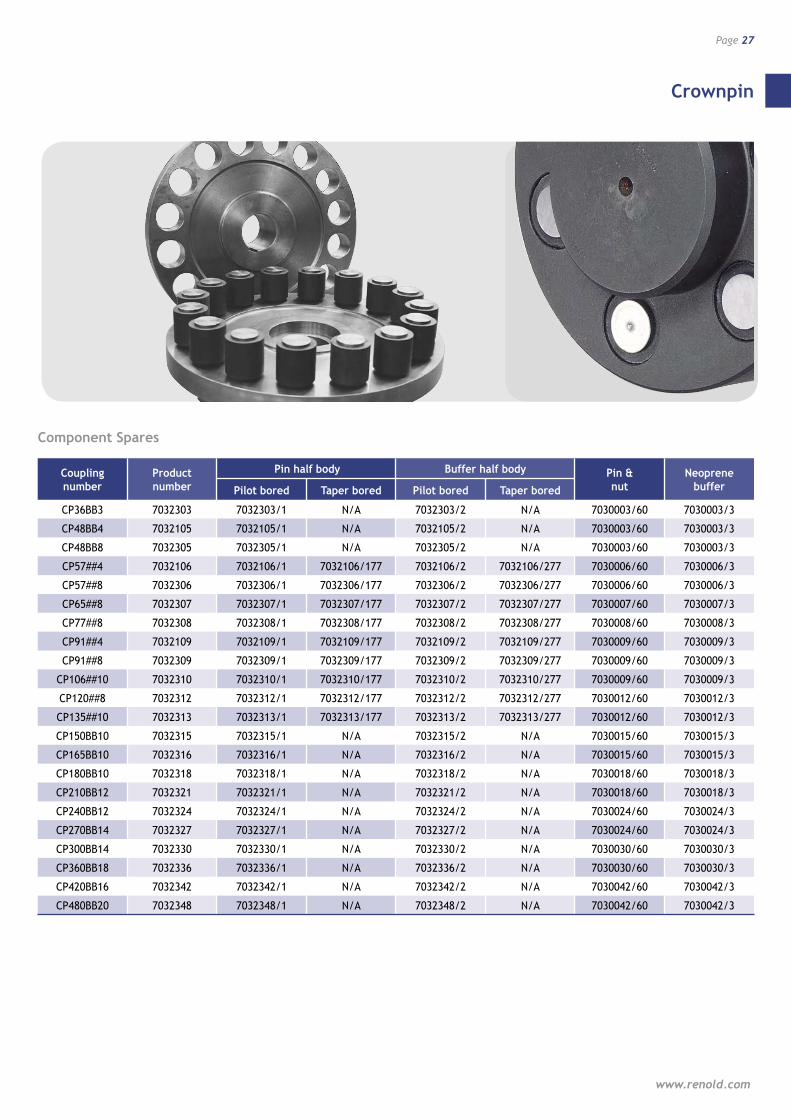
Component Spares
Coupling Product Pin half body Buffer half body Pin & Neoprene number number Pilot bored Taper bored Pilot bored Taper bored nut buffer
CP36BB3 7032303 7032303/1 N/A 7032303/2 N/A 7030003/60 7030003/3
CP48BB4 7032105 7032105/1 N/A 7032105/2 N/A 7030003/60 7030003/3
CP48BB8 7032305 7032305/1 N/A 7032305/2 N/A 7030003/60 7030003/3
CP57##4 7032106 7032106/1 7032106/177 7032106/2 7032106/277 7030006/60 7030006/3
CP57##8 7032306 7032306/1 7032306/177 7032306/2 7032306/277 7030006/60 7030006/3
CP65##8 7032307 7032307/1 7032307/177 7032307/2 7032307/277 7030007/60 7030007/3
CP77##8 7032308 7032308/1 7032308/177 7032308/2 7032308/277 7030008/60 7030008/3
CP91##4 7032109 7032109/1 7032109/177 7032109/2 7032109/277 7030009/60 7030009/3
CP91##8 7032309 7032309/1 7032309/177 7032309/2 7032309/277 7030009/60 7030009/3
CP106##10 7032310 7032310/1 7032310/177 7032310/2 7032310/277 7030009/60 7030009/3
CP120##8 7032312 7032312/1 7032312/177 7032312/2 7032312/277 7030012/60 7030012/3
CP135##10 7032313 7032313/1 7032313/177 7032313/2 7032313/277 7030012/60 7030012/3
CP150BB10 7032315 7032315/1 N/A 7032315/2 N/A 7030015/60 7030015/3
CP165BB10 7032316 7032316/1 N/A 7032316/2 N/A 7030015/60 7030015/3
CP180BB10 7032318 7032318/1 N/A 7032318/2 N/A 7030018/60 7030018/3
CP210BB12 7032321 7032321/1 N/A 7032321/2 N/A 7030018/60 7030018/3
CP240BB12 7032324 7032324/1 N/A 7032324/2 N/A 7030024/60 7030024/3
CP270BB14 7032327 7032327/1 N/A 7032327/2 N/A 7030024/60 7030024/3
CP300BB14 7032330 7032330/1 N/A 7032330/2 N/A 7030030/60 7030030/3
CP360BB18 7032336 7032336/1 N/A 7032336/2 N/A 7030030/60 7030030/3
CP420BB16 7032342 7032342/1 N/A 7032342/2 N/A 7030042/60 7030042/3
CP480BB20 7032348 7032348/1 N/A 7032348/2 N/A 7030042/60 7030042/3
Tyreflex
Page 28
Resilient and Soft Start Couplings
A range of highly flexible couplings offering excellent misalignment capacity and suitable to absorb both shock loads and vibrations.
Coupling capacity• Maximum power @ 100RPM: 65.8 kW
• Maximum torque: 6270 Nm
Features and benefits• High misalignment capabilities - high
flexibility.
• Shock absorbing - extending machine life.
• Maintenance free - minimum number of wearing parts.
• Fire retardent, anti-static elements available for use in a flameproof environment.
• Interchangeability means no re-engineering.
• Pump spacer option for easy pump maintenance.
• Taper bush bores available for ease of replacement.
• Easy replacement of tyre element without any need to move hubs axially on driven or driving shafts.
Standard range comprises• Shaft to Shaft
• Pump Spacer Type
Applications• Compressors
• Generator Sets
• Pumps
• Roller Table Drives
• General Industrial Applications
Construction detailsSteel or S.G. Iron Half Bodies
Rubber Tyres: Temp Range -50ºC to +50ºC
Chloroprene Tyres: Temp Range -15ºC to +70ºC
Can be certified for use in potentially explosive atmospheres containing gas or dust, according to ATEX directive 94/9/EC.
The couplings are classified for equipment group II, categories 2 and 3.
Contact Renold for further details.
Tyreflex
www.renold.com
Page 29
D
L1
FC1
D
L2
FC2
D
L3 P
FC3
D
L1F
MC1
D
L2F
MC2
D
L3 F P
MC3
F
L1
C1
D D D
F
L2
C2F
L3
C3
P
DD
F
L1
C1M
F
L2
C2M
D
F
L3
C3M
P
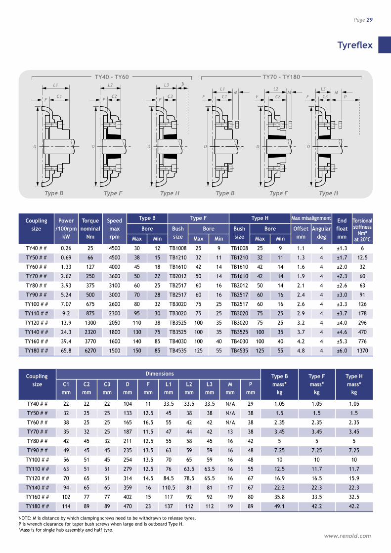
Coupling Power Torque Speed Type B Type F Type H Max misalignment End size /100rpm nominal max Bore Bush Bore Bush Bore Offset Angular float kW Nm rpm Max Min size Max Min size Max Min mm deg mm
TY40 # # 0.26 25 4500 30 12 TB1008 25 9 TB1008 25 9 1.1 4 ±1.3 6
TY50 # # 0.69 66 4500 38 15 TB1210 32 11 TB1210 32 11 1.3 4 ±1.7 12.5
TY60 # # 1.33 127 4000 45 18 TB1610 42 14 TB1610 42 14 1.6 4 ±2.0 32
TY70 # # 2.62 250 3600 50 22 TB2012 50 14 TB1610 42 14 1.9 4 ±2.3 60
TY80 # # 3.93 375 3100 60 25 TB2517 60 16 TB2012 50 14 2.1 4 ±2.6 63
TY90 # # 5.24 500 3000 70 28 TB2517 60 16 TB2517 60 16 2.4 4 ±3.0 91
TY100 # # 7.07 675 2600 80 32 TB3020 75 25 TB2517 60 16 2.6 4 ±3.3 126
TY110 # # 9.2 875 2300 95 30 TB3020 75 25 TB3020 75 25 2.9 4 ±3.7 178
TY120 # # 13.9 1300 2050 110 38 TB3525 100 35 TB3020 75 25 3.2 4 ±4.0 296
TY140 # # 24.3 2320 1800 130 75 TB3525 100 35 TB3525 100 35 3.7 4 ±4.6 470
TY160 # # 39.4 3770 1600 140 85 TB4030 100 40 TB4030 100 40 4.2 4 ±5.3 776
TY180 # # 65.8 6270 1500 150 85 TB4535 125 55 TB4535 125 55 4.8 4 ±6.0 1370
Coupling Dimensions Type B Type F Type H size C1 C2 C3 D F L1 L2 L3 M P mass* mass* mass* mm mm mm mm mm mm mm mm mm mm kg kg kg
TY40 # # 22 22 22 104 11 33.5 33.5 33.5 N/A 29 1.05 1.05 1.05
TY50 # # 32 25 25 133 12.5 45 38 38 N/A 38 1.5 1.5 1.5
TY60 # # 38 25 25 165 16.5 55 42 42 N/A 38 2.35 2.35 2.35
TY70 # # 35 32 25 187 11.5 47 44 42 13 38 3.45 3.45 3.45
TY80 # # 42 45 32 211 12.5 55 58 45 16 42 5 5 5
TY90 # # 49 45 45 235 13.5 63 59 59 16 48 7.25 7.25 7.25
TY100 # # 56 51 45 254 13.5 70 65 59 16 48 10 10 10
TY110 # # 63 51 51 279 12.5 76 63.5 63.5 16 55 12.5 11.7 11.7
TY120 # # 70 65 51 314 14.5 84.5 78.5 65.5 16 67 16.9 16.5 15.9
TY140 # # 94 65 65 359 16 110.5 81 81 17 67 22.2 22.3 22.3
TY160 # # 102 77 77 402 15 117 92 92 19 80 35.8 33.5 32.5
TY180 # # 114 89 89 470 23 137 112 112 19 89 49.1 42.2 42.2
NOTE: M is distance by which clamping screws need to be withdrawn to release tyres. P is wrench clearance for taper bush screws when large end is outboard Type H. *Mass is for single hub assembly and half tyre.
Type B Type B Type F Type HType HType F
TY40 - TY60 TY70 - TY180
Torsional stiffness
Nmº at 20ºC
Tyreflex
Page 30
Resilient and Soft Start Couplings
Component Spares
Ordering code
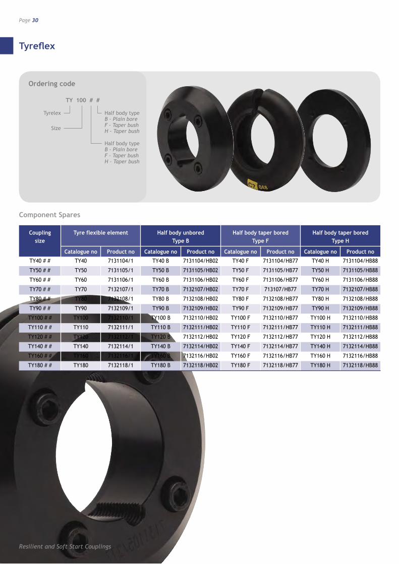
TY 100 # #
Tyrelex
Size
Half body type B – Plain bore F – Taper bush H – Taper bush
Half body type B – Plain bore F – Taper bush H – Taper bush
Coupling Tyre flexible element Half body unbored Half body taper bored Half body taper bored size Type B Type F Type H
Catalogue no Product no Catalogue no Product no Catalogue no Product no Catalogue no Product no
TY40 # # TY40 7131104/1 TY40 B 7131104/HB02 TY40 F 7131104/HB77 TY40 H 7131104/HB88
TY50 # # TY50 7131105/1 TY50 B 7131105/HB02 TY50 F 7131105/HB77 TY50 H 7131105/HB88
TY60 # # TY60 7131106/1 TY60 B 7131106/HB02 TY60 F 7131106/HB77 TY60 H 7131106/HB88
TY70 # # TY70 7132107/1 TY70 B 7132107/HB02 TY70 F 713107/HB77 TY70 H 7132107/HB88
TY80 # # TY80 7132108/1 TY80 B 7132108/HB02 TY80 F 7132108/HB77 TY80 H 7132108/HB88
TY90 # # TY90 7132109/1 TY90 B 7132109/HB02 TY90 F 7132109/HB77 TY90 H 7132109/HB88
TY100 # # TY100 7132110/1 TY100 B 7132110/HB02 TY100 F 7132110/HB77 TY100 H 7132110/HB88
TY110 # # TY110 7132111/1 TY110 B 7132111/HB02 TY110 F 7132111/HB77 TY110 H 7132111/HB88
TY120 # # TY120 7132112/1 TY120 B 7132112/HB02 TY120 F 7132112/HB77 TY120 H 7132112/HB88
TY140 # # TY140 7132114/1 TY140 B 7132114/HB02 TY140 F 7132114/HB77 TY140 H 7132114/HB88
TY160 # # TY160 7132116/1 TY160 B 7132116/HB02 TY160 F 7132116/HB77 TY160 H 7132116/HB88
TY180 # # TY180 7132118/1 TY180 B 7132118/HB02 TY180 F 7132118/HB77 TY180 H 7132118/HB88
Discflex
www.renold.com
Page 31
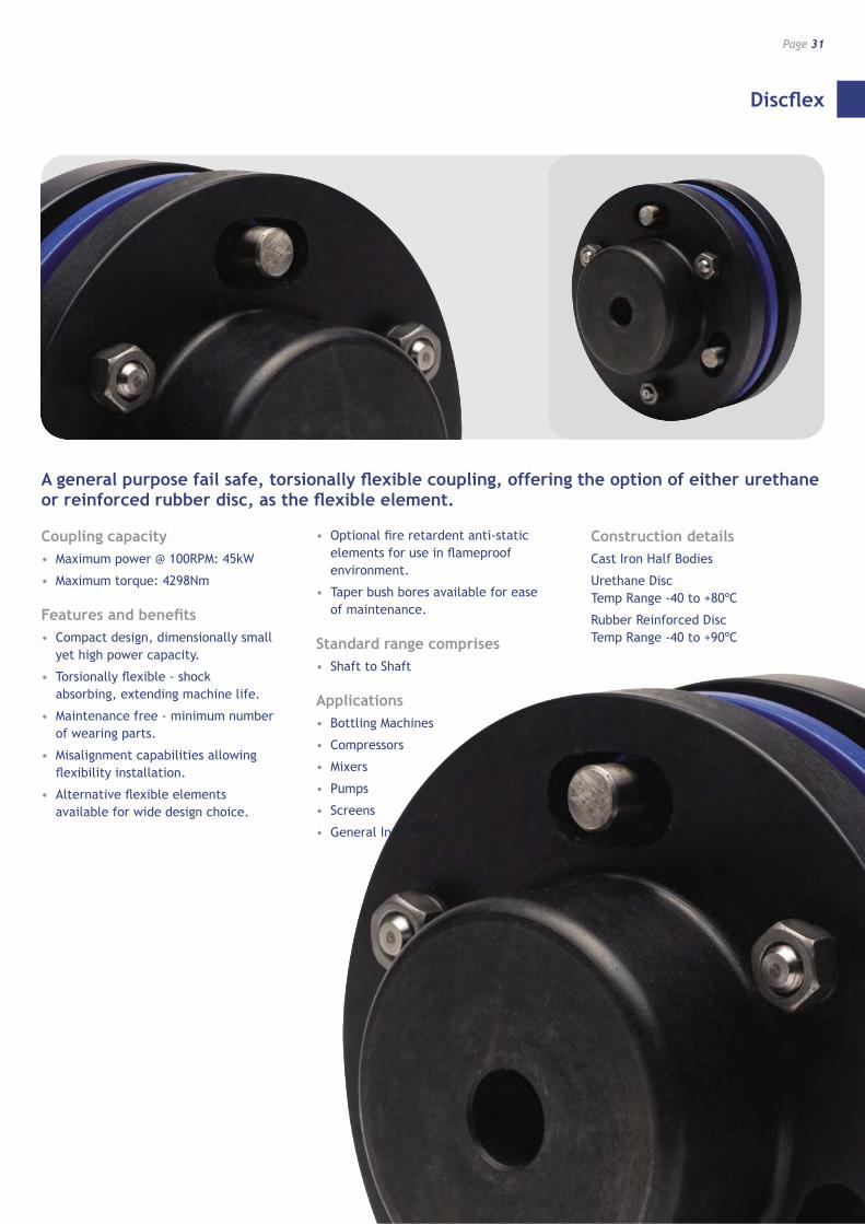
A general purpose fail safe, torsionally flexible coupling, offering the option of either urethane or reinforced rubber disc, as the flexible element.
Coupling capacity• Maximum power @ 100RPM: 45kW
• Maximum torque: 4298Nm
Features and benefits• Compact design, dimensionally small
yet high power capacity.
• Torsionally flexible - shock absorbing, extending machine life.
• Maintenance free - minimum number of wearing parts.
• Misalignment capabilities allowing flexibility installation.
• Alternative flexible elements available for wide design choice.
• Optional fire retardent anti-static elements for use in flameproof environment.
• Taper bush bores available for ease of maintenance.
Standard range comprises• Shaft to Shaft
Applications• Bottling Machines
• Compressors
• Mixers
• Pumps
• Screens
• General Industrial Applications
Construction detailsCast Iron Half Bodies
Urethane Disc Temp Range -40 to +80ºC
Rubber Reinforced Disc Temp Range -40 to +90ºC
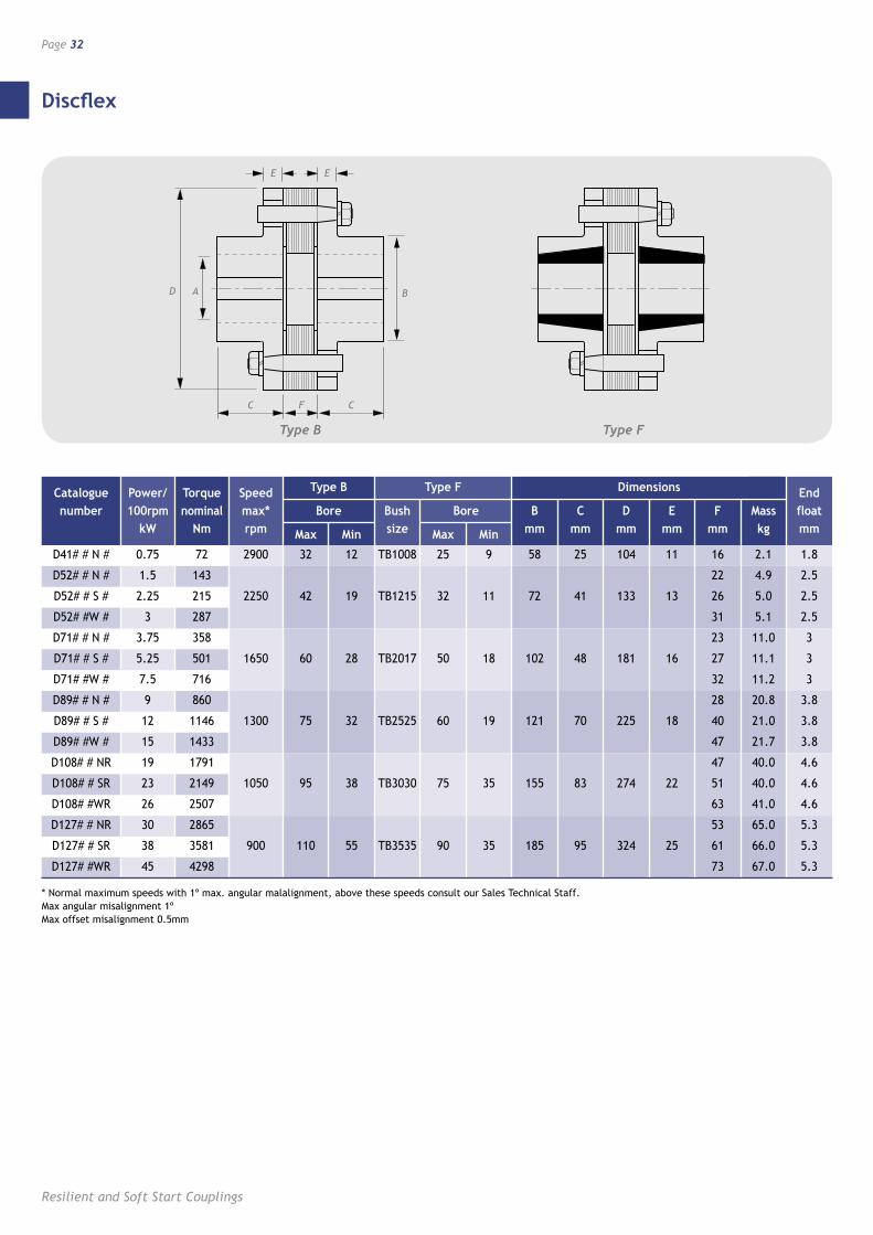
Discflex
Page 32
Resilient and Soft Start Couplings
E E
C F C
AD BBD
C
E
C
A
E
F
Catalogue Power/ Torque Speed Type B Type F Dimensions End number 100rpm nominal max* Bore Bush Bore B C D E F Mass float kW Nm rpm Max Min size Max Min mm mm mm mm mm kg mm
D41# # N # 0.75 72 2900 32 12 TB1008 25 9 58 25 104 11 16 2.1 1.8
D52# # N # 1.5 143 22 4.9 2.5
D52# # S # 2.25 215 2250 42 19 TB1215 32 11 72 41 133 13 26 5.0 2.5
D52# #W # 3 287 31 5.1 2.5
D71# # N # 3.75 358 23 11.0 3
D71# # S # 5.25 501 1650 60 28 TB2017 50 18 102 48 181 16 27 11.1 3
D71# #W # 7.5 716 32 11.2 3
D89# # N # 9 860 28 20.8 3.8
D89# # S # 12 1146 1300 75 32 TB2525 60 19 121 70 225 18 40 21.0 3.8
D89# #W # 15 1433 47 21.7 3.8
D108# # NR 19 1791 47 40.0 4.6
D108# # SR 23 2149 1050 95 38 TB3030 75 35 155 83 274 22 51 40.0 4.6
D108# #WR 26 2507 63 41.0 4.6
D127# # NR 30 2865 53 65.0 5.3
D127# # SR 38 3581 900 110 55 TB3535 90 35 185 95 324 25 61 66.0 5.3
D127# #WR 45 4298 73 67.0 5.3
* Normal maximum speeds with 1º max. angular malalignment, above these speeds consult our Sales Technical Staff. Max angular misalignment 1º Max offset misalignment 0.5mm
Type B Type F
Discflex
www.renold.com
Page 33
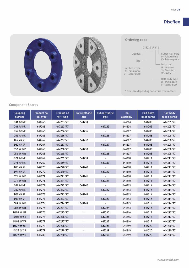
Component Spares
Coupling Product no Product no Polyurethane Rubber/fabric Pin Half body Half body number ‘BB’ type ‘FF’ type disc disc assembly pilot bored taped bored
D41 ## NP 644763 644763/77 644733 - 644204 644205 644205/77
D41 ## NR 647263 647263/77 - 647233 644204 644205 644205/77
D52 ## NP 644766 644766/77 644736 - 644207 644208 644208/77
D52 ## NR 647266 647266/77 - 647236 644207 644208 644208/77
D52 ## SP 644767 644767/77 644737 - 644207 644208 644208/77
D52 ## SR 647267 647267/77 - 647237 644207 644208 644208/77
D52 ## WP 644768 644768/77 644738 - 644207 644208 644208/77
D52 ## WR 647268 647268/77 - 647238 644207 644208 644208/77
D71 ## NP 644769 644769/77 644739 - 644210 644211 644211/77
D71 ## NR 647269 647269/77 - 647239 644210 644211 644211/77
D71 ## SP 644770 644770/77 644740 - 644210 644211 644211/77
D71 ## SR 647270 647270/77 - 647240 644210 644211 644211/77
D71 ## WP 644771 644771/77 644741 - 644210 644211 644211/77
D71 ## WR 647271 647271/77 - 647241 644210 644211 644211/77
D89 ## NP 644772 644772/77 644742 - 644213 644214 644214/77
D89 ## NR 647272 647272/77 - 647242 644213 644214 644214/77
D89 ## SP 644773 644773/77 644743 - 644213 644214 644214/77
D89 ## SR 647273 647273/77 - 647243 644213 644214 644214/77
D89 ## WP 644774 644774/77 644744 - 644213 644214 644214/77
D89 ## WR 647274 647274/77 - 647244 644213 644214 644214/77
D108 ## NR 647275 647275/77 - 647245 644216 644217 644217/77
D108 ## SR 647276 647276/77 - 647246 644216 644217 644217/77
D108 ##WR 647277 647277/77 - 647247 644216 644217 644217/77
D127 ## NR 647278 647278/77 - 647248 644219 644220 644220/77
D127 ## SR 647279 647279/77 - 647249 644219 644220 644220/77
D127 ##WR 647280 647280/77 - 647250 644219 644220 644220/77
Ordering code
D 52 # # # #
Discflex
Size
Buffer half type P – Polyurethane R – Rubber/fabric
Half body type B – Plain bore F – Taper bush
Disc size* N – Narrow S – Standard W - Wide
* Disc size depending on torque transmitted.
Half body type B – Plain bore F – Taper bush
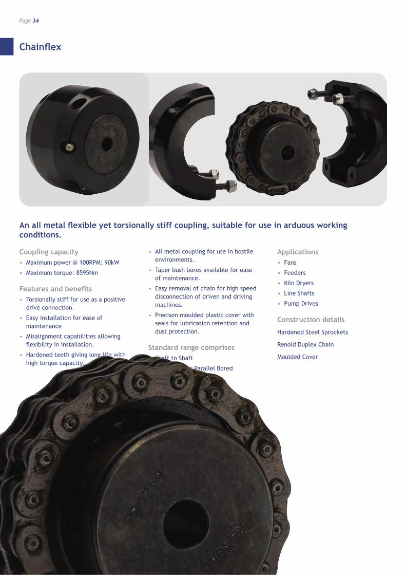
Chainflex
Page 34
Resilient and Soft Start Couplings
An all metal flexible yet torsionally stiff coupling, suitable for use in arduous working conditions.
Coupling capacity• Maximum power @ 100RPM: 90kW
• Maximum torque: 8595Nm
Features and benefits• Torsionally stiff for use as a positive
drive connection.
• Easy installation for ease of maintenance
• Misalignment capabilities allowing flexibility in installation.
• Hardened teeth giving long life with high torque capacity.
• All metal coupling for use in hostile environments.
• Taper bush bores available for ease of maintenance.
• Easy removal of chain for high speed disconnection of driven and driving machines.
• Precison moulded plastic cover with seals for lubrication retention and dust protection.
Standard range comprises• Shaft to Shaft
• Taper Bush or Parallel Bored
Applications• Fans
• Feeders
• Kiln Dryers
• Line Shafts
• Pump Drives
Construction details
Hardened Steel Sprockets
Renold Duplex Chain
Moulded Cover
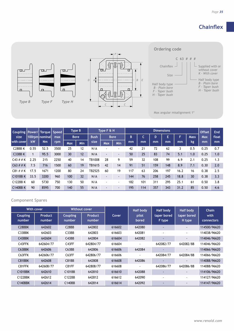
Chainflex
www.renold.com
Page 35
C
F
C
AD
TYPE H
B E
TYPE FTYPE B
D
F
C
B
Coupling Power/ Torque Speed Type B Type F & H Dimensions Offset End size 100rpm nominal max Bore Bush Bore B C D E F Mass Max float with cover kW Nm rpm Max Min size Max Min mm mm mm mm mm kg mm mm
C28BB K 0.55 52.5 3500 25 12 N/A - - 42 21 72 62 3 0.5 0.25 0.7
C33BB K 1 95.5 3000 30 12 N/A - - 50 25 83 74 5.1 1.0 0.25 1.0
C43 # # K 2.25 215 2250 40 14 TB1008 28 9 59 32 108 99 6.9 2.1 0.25 1.3
C63 # # K 7.5 716 1500 60 19 TB1615 42 14 91 51 159 148 8.9 7.1 0.30 2.0
C81 # # K 17.5 1671 1200 80 24 TB2525 60 19 117 63 206 197 16.2 16 0.38 2.5
C101BB K 33.5 3200 960 100 32 N/A - - 144 76 258 245 18.8 30 0.38 3.3
C122BB K 60 5730 750 130 50 N/A - - 182 101 311 295 25.1 61 0.50 3.8
C140BB K 90 8595 700 140 55 N/A - - 195 114 357 343 31.2 85 0.50 4.6
Ordering code
C 63 # # #
Chainflex
Size
Supplied with or without cover K – With cover
Half body type B – Plain bore F – Taper bush H – Taper bush
Half body type B – Plain bore F – Taper bush H – Taper bush
Max angular misalignment 1º
Type B Type HType F
A
C
E
Component Spares
With cover Without cover Half body Half body Half body Chain Coupling Product Coupling Product Cover pilot taper bored taper bored with number number number number bored F type H type connectors
C28BBK 642602 C28BB 642802 616602 642080 - - 114500/96620
C33BBK 642603 C33BB 642803 616603 642081 - - 114038/96620
C43BBK 642604 C43BB 642804 616604 642082 - - 114046/96620
C43FFK 642604/77 C43FF 642804/77 616604 - 642082/77 642082/88 114046/96620
C63BBK 642606 C63BB 642806 616606 642084 - - 114066/96620
C63FFK 642606/77 C63FF 642806/77 616606 - 642084/77 642084/88 114066/96620
C81BBK 642608 C81BB 642808 616608 642086 - - 114088/96620
C81FFK 642608/77 C81FF 642808/77 616608 - 642086/77 642086/88 114088/96620
C101BBK 642610 C101BB 642810 616610 642088 - - 114106/96620
C122BBK 642612 C122BB 642812 616612 642090 - - 114127/96620
C140BBK 642614 C140BB 642814 616614 642092 - - 114147/96620
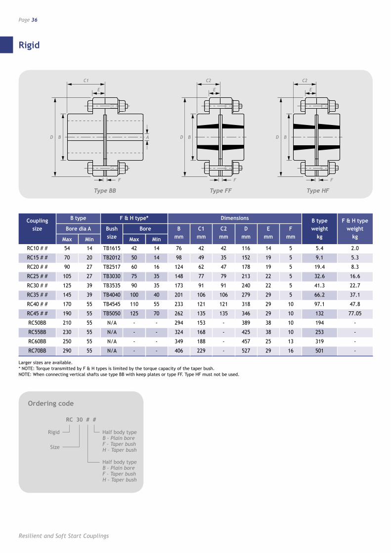
Rigid
Page 36
Resilient and Soft Start Couplings
Ordering code
RC 30 # #
Rigid
Size
Half body type B – Plain bore F – Taper bush H – Taper bush
Half body type B – Plain bore F – Taper bush H – Taper bush
B AD
E
F
C1
F F
BD BD
E
C2
E
C2
D B A
E
C1
F
D B
E
C2
F
D
E
C2
F
Coupling B type F & H type* Dimensions B type F & H type size Bore dia A Bush Bore B C1 C2 D E F weight weight Max Min size Max Min mm mm mm mm mm mm kg kg
RC10 # # 54 14 TB1615 42 14 76 42 42 116 14 5 5.4 2.0
RC15 # # 70 20 TB2012 50 14 98 49 35 152 19 5 9.1 5.3
RC20 # # 90 27 TB2517 60 16 124 62 47 178 19 5 19.4 8.3
RC25 # # 105 27 TB3030 75 35 148 77 79 213 22 5 32.6 16.6
RC30 # # 125 39 TB3535 90 35 173 91 91 240 22 5 41.3 22.7
RC35 # # 145 39 TB4040 100 40 201 106 106 279 29 5 66.2 37.1
RC40 # # 170 55 TB4545 110 55 233 121 121 318 29 10 97.1 47.8
RC45 # # 190 55 TB5050 125 70 262 135 135 346 29 10 132 77.05
RC50BB 210 55 N/A - - 294 153 - 389 38 10 194 -
RC55BB 230 55 N/A - - 324 168 - 425 38 10 253 -
RC60BB 250 55 N/A - - 349 188 - 457 25 13 319 -
RC70BB 290 55 N/A - - 406 229 - 527 29 16 501 -
Larger sizes are available. * NOTE: Torque transmitted by F & H types is limited by the torque capacity of the taper bush. NOTE: When connecting vertical shafts use type BB with keep plates or type FF. Type HF must not be used.
Type HFType FFType BB
B
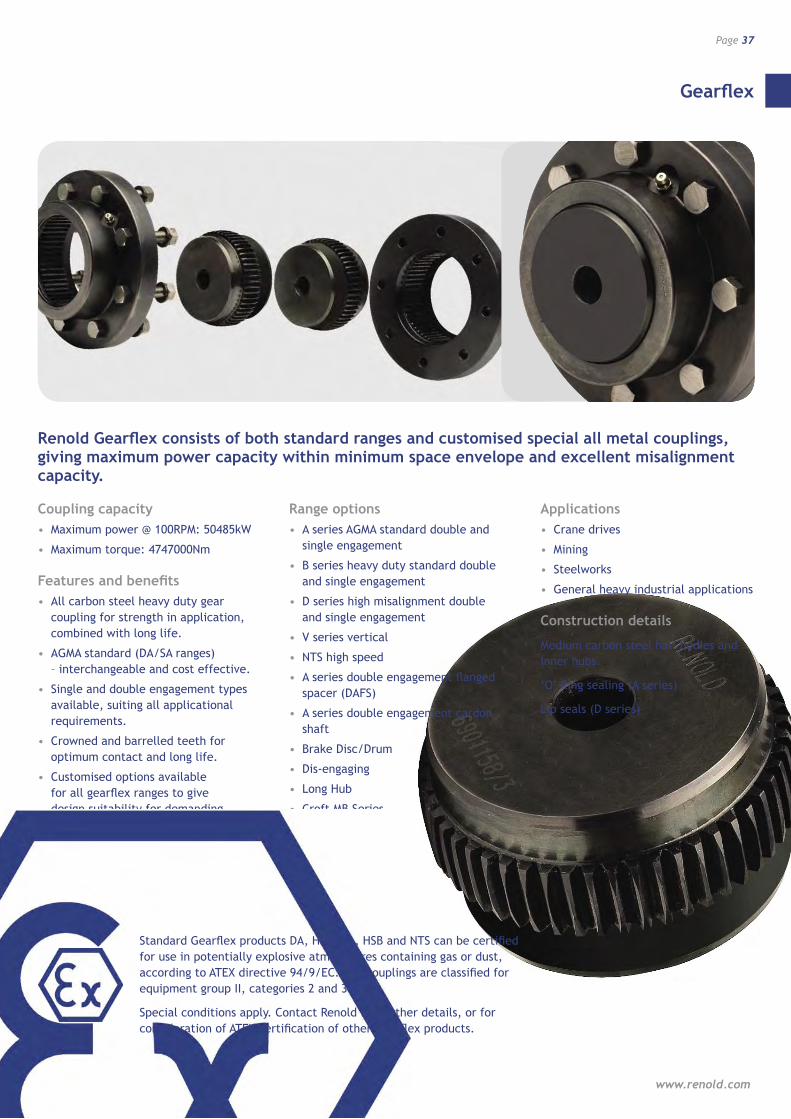
Gearflex
www.renold.com
Page 37
Renold Gearflex consists of both standard ranges and customised special all metal couplings, giving maximum power capacity within minimum space envelope and excellent misalignment capacity.
Coupling capacity• Maximum power @ 100RPM: 50485kW
• Maximum torque: 4747000Nm
Features and benefits• All carbon steel heavy duty gear
coupling for strength in application, combined with long life.
• AGMA standard (DA/SA ranges) – interchangeable and cost effective.
• Single and double engagement types available, suiting all applicational requirements.
• Crowned and barrelled teeth for optimum contact and long life.
• Customised options available for all gearflex ranges to give design suitability for demanding applications.
• High misalignment up to 6o
Range options• A series AGMA standard double and
single engagement
• B series heavy duty standard double and single engagement
• D series high misalignment double and single engagement
• V series vertical
• NTS high speed
• A series double engagement flanged spacer (DAFS)
• A series double engagement cardon shaft
• Brake Disc/Drum
• Dis-engaging
• Long Hub
• Croft MB Series
• Mill Motor
• Shear Pin
• Telescopic
Applications• Crane drives
• Mining
• Steelworks
• General heavy industrial applications
Construction details
Medium carbon steel half bodies and inner hubs.
‘O’ Ring sealing (A series)
Lip seals (D series)
Standard Gearflex products DA, HDB, SA, HSB and NTS can be certified for use in potentially explosive atmospheres containing gas or dust, according to ATEX directive 94/9/EC. The couplings are classified for equipment group II, categories 2 and 3.
Special conditions apply. Contact Renold for further details, or for consideration of ATEX certification of other Gearflex products.
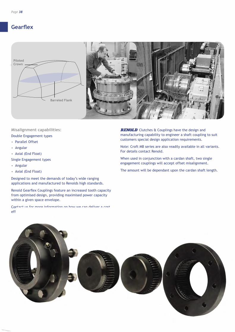
Gearflex
Page 38
Resilient and Soft Start Couplings
Barreled Flank
Piloted Crown
Misalignment capabilities:Double Engagement types
• Parallel Offset
• Angular
• Axial (End Float)
Single Engagement types
• Angular
• Axial (End Float)
Designed to meet the demands of today’s wide ranging applications and manufactured to Renolds high standards.
Renold Gearflex Couplings feature an increased tooth capacity from optimised design, providing maximised power capacity within a given space envelope.
Contact us for more information on how we can deliver a cost effective solution to your application.
Clutches & Couplings have the design and manufacturing capability to engineer a shaft coupling to suit customers special design application requirements.
Note: Croft MB series are also readily available in all variants. For details contact Renold.
When used in conjunction with a cardan shaft, two single engagement couplings will accept offset misalignment.
The amount will be dependant upon the cardan shaft length.
Piloted Crown
Barreled Flank
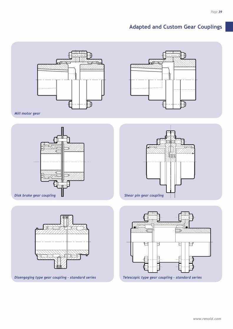
Adapted and Custom Gear Couplings
www.renold.com
Page 39
PAGE 33 A/W
THE ILLUSTRATION�IN THIS SPOT IS�
ALSO DUPLICATED�ON PAGE 32
PAGE 33 A/W
THE ILLUSTRATION�IN THIS SPOT IS�
ALSO DUPLICATED�ON PAGE 32
PAGE 32 A/W
PAGE 32 A/W
Mill motor gear
Disengaging type gear coupling – standard series Telescopic type gear coupling – standard series
Disk brake gear coupling Shear pin gear coupling
F3
L3
F2
L2
REVERSED
REVERSED REVERSED
NORMAL
STOP PLATE
B DA
C C
F1
L1
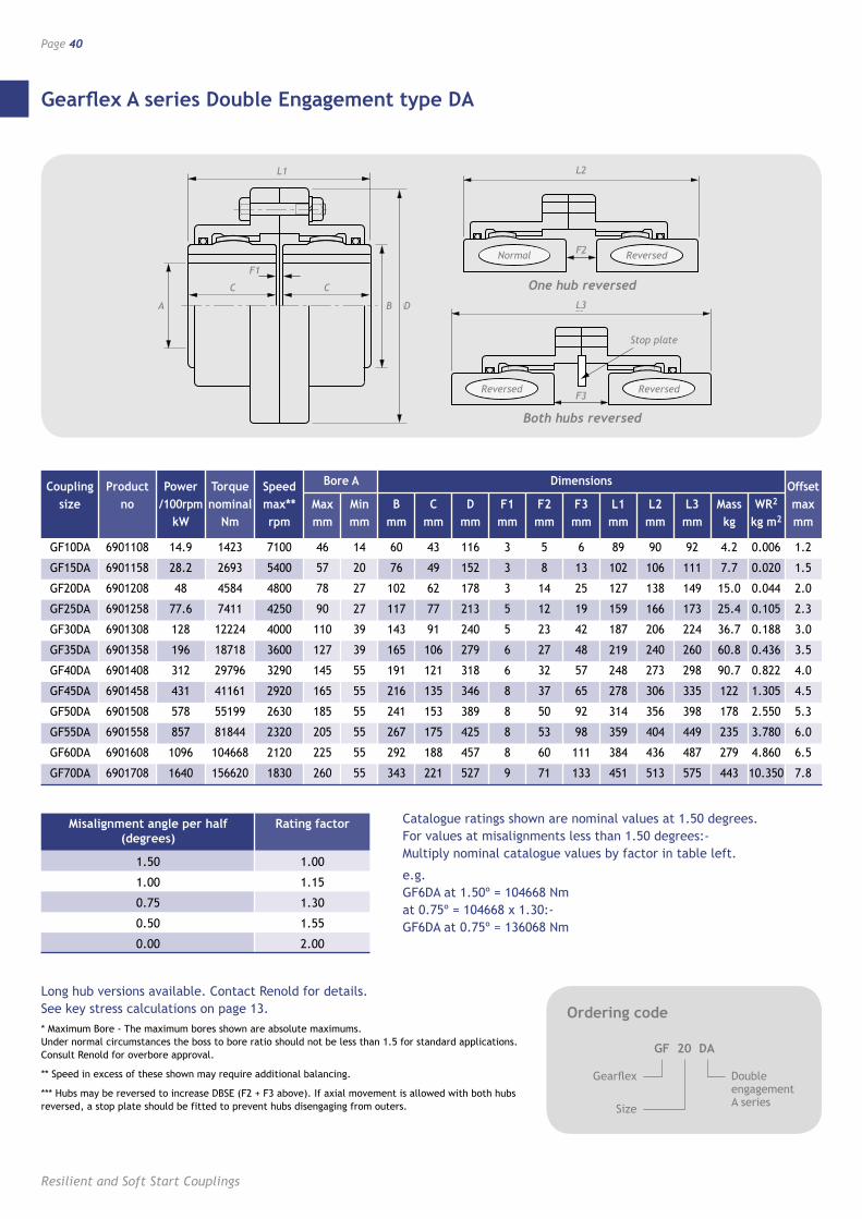
Gearflex A series Double Engagement type DA
Page 40
Resilient and Soft Start Couplings
L2
L3
F3
Stop plate
F2
Coupling Product Power Torque Speed Bore A Dimensions Offset size no /100rpm nominal max** Max Min B C D F1 F2 F3 L1 L2 L3 Mass WR2 max kW Nm rpm mm mm mm mm mm mm mm mm mm mm mm kg kg m2 mm
GF10DA 6901108 14.9 1423 7100 46 14 60 43 116 3 5 6 89 90 92 4.2 0.006 1.2
GF15DA 6901158 28.2 2693 5400 57 20 76 49 152 3 8 13 102 106 111 7.7 0.020 1.5
GF20DA 6901208 48 4584 4800 78 27 102 62 178 3 14 25 127 138 149 15.0 0.044 2.0
GF25DA 6901258 77.6 7411 4250 90 27 117 77 213 5 12 19 159 166 173 25.4 0.105 2.3
GF30DA 6901308 128 12224 4000 110 39 143 91 240 5 23 42 187 206 224 36.7 0.188 3.0
GF35DA 6901358 196 18718 3600 127 39 165 106 279 6 27 48 219 240 260 60.8 0.436 3.5
GF40DA 6901408 312 29796 3290 145 55 191 121 318 6 32 57 248 273 298 90.7 0.822 4.0
GF45DA 6901458 431 41161 2920 165 55 216 135 346 8 37 65 278 306 335 122 1.305 4.5
GF50DA 6901508 578 55199 2630 185 55 241 153 389 8 50 92 314 356 398 178 2.550 5.3
GF55DA 6901558 857 81844 2320 205 55 267 175 425 8 53 98 359 404 449 235 3.780 6.0
GF60DA 6901608 1096 104668 2120 225 55 292 188 457 8 60 111 384 436 487 279 4.860 6.5
GF70DA 6901708 1640 156620 1830 260 55 343 221 527 9 71 133 451 513 575 443 10.350 7.8
L1
C C
A DB
F1Normal Reversed
ReversedReversed
Ordering code
GF 20 DA
Gearflex
Size
Double engagement A series
Misalignment angle per half Rating factor (degrees)
1.50 1.00
1.00 1.15
0.75 1.30
0.50 1.55
0.00 2.00
Catalogue ratings shown are nominal values at 1.50 degrees. For values at misalignments less than 1.50 degrees:- Multiply nominal catalogue values by factor in table left.
e.g. GF6DA at 1.50º = 104668 Nm at 0.75º = 104668 x 1.30:- GF6DA at 0.75º = 136068 Nm
Long hub versions available. Contact Renold for details. See key stress calculations on page 13.* Maximum Bore - The maximum bores shown are absolute maximums. Under normal circumstances the boss to bore ratio should not be less than 1.5 for standard applications. Consult Renold for overbore approval.
** Speed in excess of these shown may require additional balancing.
*** Hubs may be reversed to increase DBSE (F2 + F3 above). If axial movement is allowed with both hubs reversed, a stop plate should be fitted to prevent hubs disengaging from outers.
One hub reversed
Both hubs reversed
B
M
1
2
L
F
M
AD E
C C
�
B
M
1
2
L
F
M
AD E
C C
�
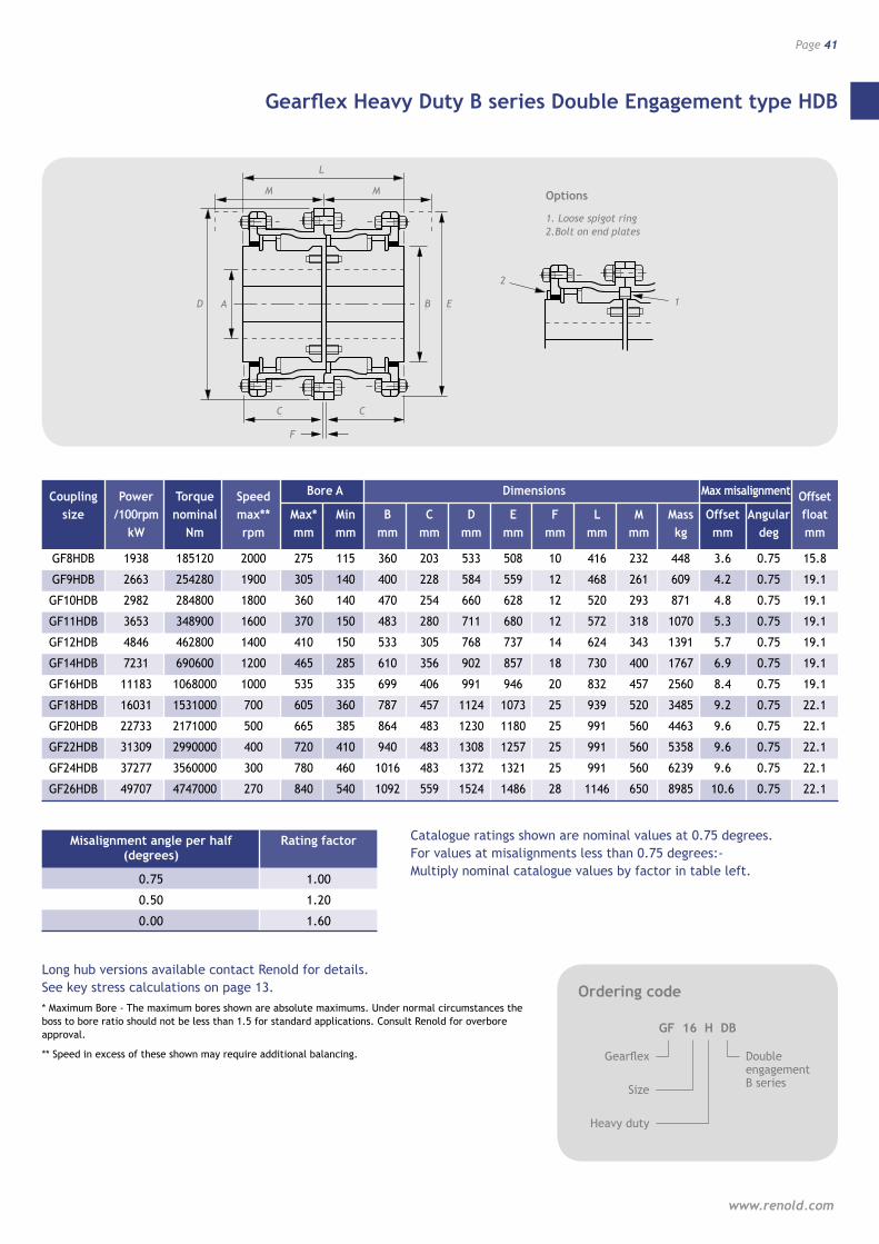
Gearflex Heavy Duty B series Double Engagement type HDB
www.renold.com
Page 41
Coupling Power Torque Speed Bore A Dimensions Max misalignment Offset size /100rpm nominal max** Max* Min B C D E F L M Mass Offset Angular float kW Nm rpm mm mm mm mm mm mm mm mm mm kg mm deg mm
GF8HDB 1938 185120 2000 275 115 360 203 533 508 10 416 232 448 3.6 0.75 15.8
GF9HDB 2663 254280 1900 305 140 400 228 584 559 12 468 261 609 4.2 0.75 19.1
GF10HDB 2982 284800 1800 360 140 470 254 660 628 12 520 293 871 4.8 0.75 19.1
GF11HDB 3653 348900 1600 370 150 483 280 711 680 12 572 318 1070 5.3 0.75 19.1
GF12HDB 4846 462800 1400 410 150 533 305 768 737 14 624 343 1391 5.7 0.75 19.1
GF14HDB 7231 690600 1200 465 285 610 356 902 857 18 730 400 1767 6.9 0.75 19.1
GF16HDB 11183 1068000 1000 535 335 699 406 991 946 20 832 457 2560 8.4 0.75 19.1
GF18HDB 16031 1531000 700 605 360 787 457 1124 1073 25 939 520 3485 9.2 0.75 22.1
GF20HDB 22733 2171000 500 665 385 864 483 1230 1180 25 991 560 4463 9.6 0.75 22.1
GF22HDB 31309 2990000 400 720 410 940 483 1308 1257 25 991 560 5358 9.6 0.75 22.1
GF24HDB 37277 3560000 300 780 460 1016 483 1372 1321 25 991 560 6239 9.6 0.75 22.1
GF26HDB 49707 4747000 270 840 540 1092 559 1524 1486 28 1146 650 8985 10.6 0.75 22.1
Misalignment angle per half Rating factor (degrees)
0.75 1.00
0.50 1.20
0.00 1.60
Catalogue ratings shown are nominal values at 0.75 degrees. For values at misalignments less than 0.75 degrees:- Multiply nominal catalogue values by factor in table left.
Long hub versions available contact Renold for details. See key stress calculations on page 13.* Maximum Bore - The maximum bores shown are absolute maximums. Under normal circumstances the boss to bore ratio should not be less than 1.5 for standard applications. Consult Renold for overbore approval.
** Speed in excess of these shown may require additional balancing.
Ordering code
GF 16 H DB
Gearflex
Size
Double engagement B series
Heavy duty
1
2
Options
1. Loose spigot ring 2.Bolt on end plates
L
M M
A EB
C
D
F
C
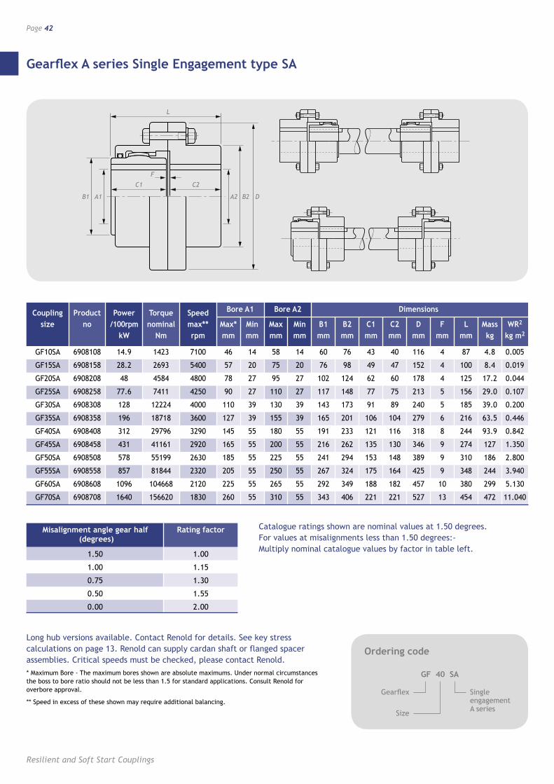
Gearflex A series Single Engagement type SA
Resilient and Soft Start Couplings
Page 42
Coupling Product Power Torque Speed Bore A1 Bore A2 Dimensions
size no /100rpm nominal max** Max* Min Max Min B1 B2 C1 C2 D F L Mass WR2
kW Nm rpm mm mm mm mm mm mm mm mm mm mm mm kg kg m2
GF10SA 6908108 14.9 1423 7100 46 14 58 14 60 76 43 40 116 4 87 4.8 0.005
GF15SA 6908158 28.2 2693 5400 57 20 75 20 76 98 49 47 152 4 100 8.4 0.019
GF20SA 6908208 48 4584 4800 78 27 95 27 102 124 62 60 178 4 125 17.2 0.044
GF25SA 6908258 77.6 7411 4250 90 27 110 27 117 148 77 75 213 5 156 29.0 0.107
GF30SA 6908308 128 12224 4000 110 39 130 39 143 173 91 89 240 5 185 39.0 0.200
GF35SA 6908358 196 18718 3600 127 39 155 39 165 201 106 104 279 6 216 63.5 0.446
GF40SA 6908408 312 29796 3290 145 55 180 55 191 233 121 116 318 8 244 93.9 0.842
GF45SA 6908458 431 41161 2920 165 55 200 55 216 262 135 130 346 9 274 127 1.350
GF50SA 6908508 578 55199 2630 185 55 225 55 241 294 153 148 389 9 310 186 2.800
GF55SA 6908558 857 81844 2320 205 55 250 55 267 324 175 164 425 9 348 244 3.940
GF60SA 6908608 1096 104668 2120 225 55 265 55 292 349 188 182 457 10 380 299 5.130
GF70SA 6908708 1640 156620 1830 260 55 310 55 343 406 221 221 527 13 454 472 11.040
Misalignment angle gear half Rating factor (degrees)
1.50 1.00
1.00 1.15
0.75 1.30
0.50 1.55
0.00 2.00
Catalogue ratings shown are nominal values at 1.50 degrees. For values at misalignments less than 1.50 degrees:- Multiply nominal catalogue values by factor in table left.
Long hub versions available. Contact Renold for details. See key stress calculations on page 13. Renold can supply cardan shaft or flanged spacer assemblies. Critical speeds must be checked, please contact Renold.* Maximum Bore - The maximum bores shown are absolute maximums. Under normal circumstances the boss to bore ratio should not be less than 1.5 for standard applications. Consult Renold for overbore approval.
** Speed in excess of these shown may require additional balancing.
B2 DA1 A2B1
C1 C2
F
LL
C1 C2
B1 DA2
F
A1 B2
Ordering code
GF 40 SA
Gearflex
Size
Single engagement A series
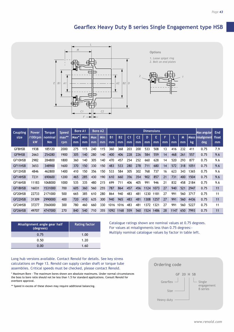
��
�
�
�
����� �� �
�� ��
�
A2
M
12
L
F
A1B1E B2 D
C1 C2
�
Gearflex Heavy Duty B series Single Engagement type HSB
www.renold.com
Page 43
Misalignment angle gear half Rating factor (degrees)
0.75 1.00
0.50 1.20
0.00 1.60
Catalogue ratings shown are nominal values at 0.75 degrees. For values at misalignments less than 0.75 degrees:- Multiply nominal catalogue values by factor in table left.
Long hub versions available. Contact Renold for details. See key stress calculations on Page 13. Renold can supply cardan shaft or torque tube assemblies. Critical speeds must be checked, please contact Renold.* Maximum Bore - The maximum bores shown are absolute maximums. Under normal circumstances the boss to bore ratio should not be less than 1.5 for standard applications. Consult Renold for overbore approval.
** Speed in excess of these shown may require additional balancing.
Ordering code
GF 20 H SB
Gearflex
Size
Single engagement B series
Heavy duty
12
Options
1. Loose spigot ring 2. Bolt on end plates
L
M
A1 B2A2
C1
B1
F
C2
DE
Coupling Power Torque Speed Bore A1 Bore A2 Dimensions Max angular End size /100rpm nominal max** Max* Min Max Min B1 B2 C1 C2 D E F L M Mass misalignment float kW Nm rpm mm mm mm mm mm mm mm mm mm mm mm mm mm kg deg mm
GF8HSB 1938 185120 2000 275 115 240 115 360 368 203 200 533 508 13 416 232 411 0.75 7.9
GF9HSB 2663 254280 1900 305 140 280 140 400 406 228 226 584 559 14 468 261 557 0.75 9.6
GF10HSB 2982 284800 1800 360 140 305 140 470 457 254 252 660 628 14 520 293 877 0.75 9.6
GF11HSB 3653 348900 1600 370 150 330 150 483 533 280 278 711 680 14 572 318 1051 0.75 9.6
GF12HSB 4846 462800 1400 410 150 356 150 533 584 305 302 768 737 16 623 343 1365 0.75 9.6
GF14HSB 7231 690600 1200 465 285 430 190 610 660 356 354 902 857 21 731 400 1504 0.75 9.6
GF16HSB 11183 1068000 1000 535 335 480 215 699 711 406 405 991 946 21 832 458 2184 0.75 9.6
GF18HSB 16031 1531000 700 605 360 560 255 787 864 457 456 1124 1073 27 940 521 2947 0.75 11
GF20HSB 22733 2171000 500 665 385 610 280 864 940 483 481 1230 1181 27 991 560 3717 0.75 11
GF22HSB 31309 2990000 400 720 410 635 300 940 965 483 481 1308 1257 27 991 560 4436 0.75 11
GF24HSB 37277 3560000 300 780 460 660 330 1016 1016 483 481 1372 1321 27 991 560 5227 0.75 11
GF26HSB 49707 4747000 270 840 540 710 355 1092 1168 559 560 1524 1486 28 1147 650 7993 0.75 11
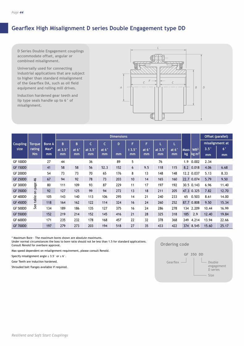
Gearflex High Misalignment D series Double Engagement type DD
Resilient and Soft Start Couplings
Page 44
Ordering code
GF 350 DD
Gearflex Double engagement D series
* Maximum Bore - The maximum bores shown are absolute maximums. Under normal circumstances the boss to bore ratio should not be less than 1.5 for standard applications. Consult Renold for overbore approval.
Max speed dependent on misalignment requirement, please consult Renold.
Specify misalignment angle ± 3.5° or ± 6°.
Gear Teeth are induction hardened.
Shrouded bolt flanges available if required.
Size
D Series Double Engagement couplings accommodate offset, angular or combined misalignment.
Universally used for connecting industrial applications that are subject to higher than standard misalignment of the Gearflex DA, such as oil field equipment and rolling mill drives.
Induction hardened gear teeth and lip type seals handle up to 6° of misalignment.
L
C C
B
F
D
Dimensions Offset (parallel)
Coupling Torque Bore A B B C C D F F L L misalignment at
size rating Max* at 3.5° at 6° at 3.5° at 6° t 3.5° at 6° at 3.5° at 6° Mass WR2 3.5° 6° Nm mm mm mm mm mm mm mm mm mm mm kg kg m2 mm mm
GF 100DD 27 44 36 89 5 76 1.9 0.002 2.34
GF 150DD 41 58 58 56 52.3 152 6 9.5 118 115 8.2 0.018 4.06 6.68
GF 200DD 54 73 73 70 65 176 8 13 148 148 12.2 0.037 5.13 8.33
GF 250DD 67 94 92 78 73 203 10 14 165 160 22.7 0.074 5.79 9.50
GF 300DD 80 111 109 93 87 229 11 17 197 192 30.5 0.143 6.96 11.40
GF 350DD 92 127 125 99 94 272 13 18 211 205 47.3 0.325 7.82 12.70
GF 400DD 105 143 140 113 106 295 14 21 240 233 65 0.503 8.61 14.00
GF 450DD 118 164 162 122 114 324 16 24 260 252 87.7 0.808 9.50 15.34
GF 500DD 134 189 186 135 127 375 16 24 286 278 134 2.209 10.44 16.99
GF 550DD 152 219 214 152 145 416 21 28 325 318 185 2.9 12.40 19.84
GF 600DD 171 235 232 178 168 457 22 32 378 368 249 4.214 13.94 22.66
GF 700DD 197 279 273 203 194 518 27 35 433 422 374 8.545 15.60 25.17
See
tabl
e on
pag
e 46
A
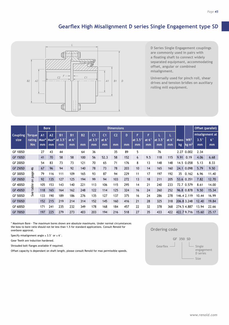
Gearflex High Misalignment D series Single Engagement type SD
www.renold.com
Page 45
Ordering code
GF 350 SD
Gearflex Single engagement D series
Size
D Series Single Engagement couplings are commonly used in pairs with a floating shaft to connect widely separated equipmant, accommodating offset, angular or combined misalignment.
Universally used for pinch roll, shear drives and tension bridles on auxiliary rolling mill equipment.
* Maximum Bore - The maximum bores shown are absolute maximums. Under normal circumstances the boss to bore ratio should not be less than 1.5 for standard applications. Consult Renold for overbore approval.
Specify misalignment angle ± 3.5° or ± 6°.
Gear Teeth are induction hardened.
Shrouded bolt flanges available if required.
Offset capacity is dependant on shaft length, please consult Renold for max permissible speeds.
L
C2 C1A1
F
B1
Bore Dimensions Offset (parallel)
Coupling Torque A1 A2 B1 B1 B2 C1 C1 C2 D F F L L misalignment at
size rating Max* Max* at 3.5° at 6° at 3.5° at 6° at 3.5° at 6° at 3.5° at 6° Mass WR2 3.5° 6° Nm mm mm mm mm mm mm mm mm mm mm mm mm mm kg kg m2 mm mm
GF 100SD 27 43 44 64 36 35 89 5 76 2.27 0.002 2.34
GF 150SD 41 70 58 58 100 56 52.3 58 152 6 9.5 118 115 9.91 0.19 4.06 6.68
GF 200SD 54 83 73 73 121 70 65 71 176 8 13 148 148 14.5 0.058 5.13 8.33
GF 250SD 67 96 94 92 140 78 73 78 203 10 14 165 160 24.1 0.098 5.79 9.50
GF 300SD 79 116 111 109 165 93 87 94 229 11 17 197 192 35 0.162 6.96 11.40
GF 350SD 92 135 127 125 194 99 94 103 272 13 18 211 205 53.6 0.351 7.82 12.70
GF 400SD 105 153 143 140 221 113 106 115 295 14 21 240 233 72.7 0.579 8.61 14.00
GF 450SD 118 165 164 162 248 122 114 125 324 16 24 260 252 96.8 0.878 9.50 15.34
GF 500SD 133 190 189 186 276 135 127 137 375 16 24 286 278 146.4 2.119 10.44 16.99
GF 550SD 152 215 219 214 314 152 145 160 416 21 28 325 318 206.8 3.248 12.40 19.84
GF 600SD 171 241 235 232 349 178 168 184 457 22 32 378 368 274.5 4.887 13.94 22.66
GF 700SD 197 225 279 273 403 203 194 216 518 27 35 433 422 422.7 9.716 15.60 25.17
See
tabl
e on
pag
e 46
DA2B2
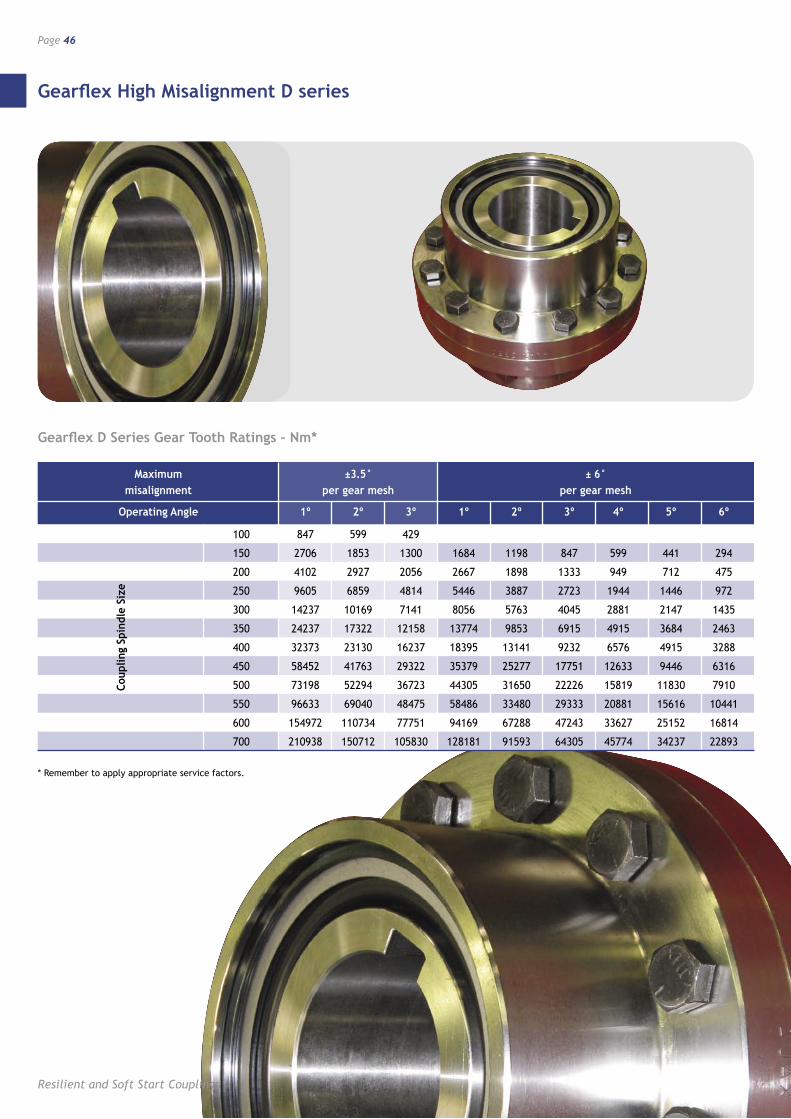
Gearflex High Misalignment D series
Resilient and Soft Start Couplings
Page 46
Maximum ±3.5° ± 6° misalignment per gear mesh per gear mesh
Operating Angle 1º 2º 3º 1º 2º 3º 4º 5º 6º
100 847 599 429
150 2706 1853 1300 1684 1198 847 599 441 294
200 4102 2927 2056 2667 1898 1333 949 712 475
250 9605 6859 4814 5446 3887 2723 1944 1446 972
300 14237 10169 7141 8056 5763 4045 2881 2147 1435
350 24237 17322 12158 13774 9853 6915 4915 3684 2463
400 32373 23130 16237 18395 13141 9232 6576 4915 3288
450 58452 41763 29322 35379 25277 17751 12633 9446 6316
500 73198 52294 36723 44305 31650 22226 15819 11830 7910
550 96633 69040 48475 58486 33480 29333 20881 15616 10441
600 154972 110734 77751 94169 67288 47243 33627 25152 16814
700 210938 150712 105830 128181 91593 64305 45774 34237 22893
Coup
ling
Spin
dle
Size
Gearflex D Series Gear Tooth Ratings – Nm*
* Remember to apply appropriate service factors.
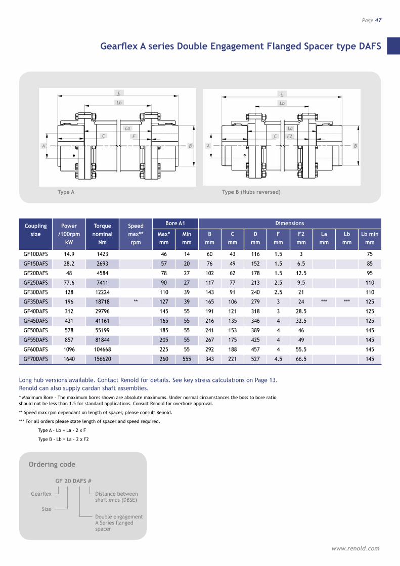
Gearflex A series Double Engagement Flanged Spacer type DAFS
www.renold.com
Page 47
Coupling Power Torque Speed Bore A1 Dimensions
size /100rpm nominal max** Max* Min B C D F F2 La Lb Lb min kW Nm rpm mm mm mm mm mm mm mm mm mm mm
GF10DAFS 14.9 1423 46 14 60 43 116 1.5 3 75
GF15DAFS 28.2 2693 57 20 76 49 152 1.5 6.5 85
GF20DAFS 48 4584 78 27 102 62 178 1.5 12.5 95
GF25DAFS 77.6 7411 90 27 117 77 213 2.5 9.5 110
GF30DAFS 128 12224 110 39 143 91 240 2.5 21 110
GF35DAFS 196 18718 ** 127 39 165 106 279 3 24 *** *** 125
GF40DAFS 312 29796 145 55 191 121 318 3 28.5 125
GF45DAFS 431 41161 165 55 216 135 346 4 32.5 125
GF50DAFS 578 55199 185 55 241 153 389 4 46 145
GF55DAFS 857 81844 205 55 267 175 425 4 49 145
GF60DAFS 1096 104668 225 55 292 188 457 4 55.5 145
GF70DAFS 1640 156620 260 555 343 221 527 4.5 66.5 145
L
A B
C
Long hub versions available. Contact Renold for details. See key stress calculations on Page 13. Renold can also supply cardan shaft assemblies. * Maximum Bore - The maximum bores shown are absolute maximums. Under normal circumstances the boss to bore ratio should not be less than 1.5 for standard applications. Consult Renold for overbore approval.
** Speed max rpm dependant on length of spacer, please consult Renold.
*** For all orders please state length of spacer and speed required.
Type A - Lb = La - 2 x F
Type B - Lb = La - 2 x F2
Ordering code
GF 20 DAFS #
Gearflex
Size
Distance between shaft ends (DBSE)
Double engagement A Series flanged spacer
F
Lb
La
L
A B
C F2
Lb
La
Type A Type B (Hubs reversed)
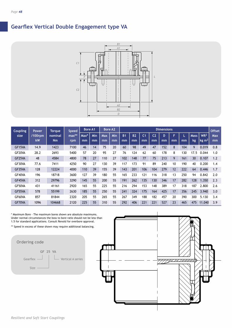
Gearflex Vertical Double Engagement type VA
Resilient and Soft Start Couplings
Page 48
* Maximum Bore - The maximum bores shown are absolute maximums. Under normal circumstances the boss to bore ratio should not be less than 1.5 for standard applications. Consult Renold for overbore approval.
** Speed in excess of these shown may require additional balancing.
Ordering code
GF 25 VA
Gearflex
Size
Vertical A series
Coupling Power Torque Speed Bore A1 Bore A2 Dimensions Offset size /100rpm nominal max** Max* Min Max Min B1 B2 C1 C2 D F L Mass WR2 Max kW Nm rpm mm mm mm mm mm mm mm mm mm mm mm kg kg m2 mm
GF15VA 14.9 1423 7100 46 14 75 20 60 98 49 47 152 8 104 9 0.019 0.8
GF20VA 28.2 2693 5400 57 20 95 27 76 124 62 60 178 8 130 17.5 0.044 1.0
GF25VA 48 4584 4800 78 27 110 27 102 148 77 75 213 9 161 30 0.107 1.2
GF30VA 77.6 7411 4250 90 27 130 39 117 173 91 89 240 10 190 40 0.200 1.4
GF35VA 128 12224 4000 110 39 155 39 143 201 106 104 279 12 222 64 0.446 1.7
GF40VA 196 18718 3600 127 39 180 55 165 233 121 116 318 13 250 94 0.842 2.0
GF45VA 312 29796 3290 145 55 200 55 191 262 135 130 346 17 282 128 1.350 2.3
GF50VA 431 41161 2920 165 55 225 55 216 294 153 148 389 17 318 187 2.800 2.6
GF55VA 578 55199 2630 185 55 250 55 241 324 175 164 425 17 356 245 3.940 3.0
GF60VA 857 81844 2320 205 55 265 55 267 349 188 182 457 20 390 300 5.130 3.4
GF70VA 1096 104668 2120 225 55 310 55 292 406 221 221 527 23 465 475 11.040 3.9
PAGE 33 A/W
THE ILLUSTRATION�IN THIS SPOT IS�
ALSO DUPLICATED�ON PAGE 32
L
A2
F
A1
B2
D
B1
C1
C2
C1
A2
F
C2
B2
D
B1A1
L
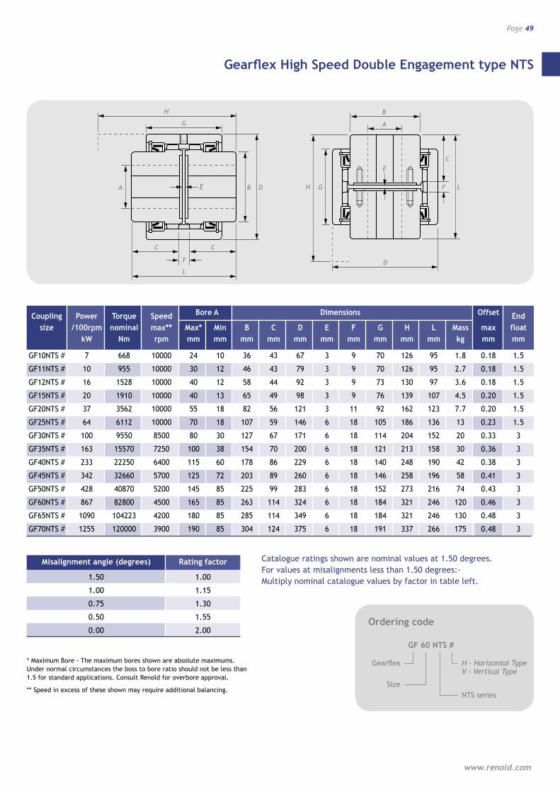
BE
F
L
A G F L H D
C
G
C C
B
A
E
D
H
L
A B
C
* Maximum Bore - The maximum bores shown are absolute maximums. Under normal circumstances the boss to bore ratio should not be less than 1.5 for standard applications. Consult Renold for overbore approval.
** Speed in excess of these shown may require additional balancing.
Ordering code
GF 60 NTS #
Gearflex
Size
H - Horizontal Type V - Vertical Type
NTS series
F
H
E D
C
G
D
A
B
F LG
E
H
C
Catalogue ratings shown are nominal values at 1.50 degrees. For values at misalignments less than 1.50 degrees:- Multiply nominal catalogue values by factor in table left.
Misalignment angle (degrees) Rating factor
1.50 1.00
1.00 1.15
0.75 1.30
0.50 1.55
0.00 2.00
Coupling Power Torque Speed Bore A Dimensions Offset End size /100rpm nominal max** Max* Min B C D E F G H L Mass max float kW Nm rpm mm mm mm mm mm mm mm mm mm mm kg mm mm
GF10NTS # 7 668 10000 24 10 36 43 67 3 9 70 126 95 1.8 0.18 1.5
GF11NTS # 10 955 10000 30 12 46 43 79 3 9 70 126 95 2.7 0.18 1.5
GF12NTS # 16 1528 10000 40 12 58 44 92 3 9 73 130 97 3.6 0.18 1.5
GF15NTS # 20 1910 10000 40 13 65 49 98 3 9 76 139 107 4.5 0.20 1.5
GF20NTS # 37 3562 10000 55 18 82 56 121 3 11 92 162 123 7.7 0.20 1.5
GF25NTS # 64 6112 10000 70 18 107 59 146 6 18 105 186 136 13 0.23 1.5
GF30NTS # 100 9550 8500 80 30 127 67 171 6 18 114 204 152 20 0.33 3
GF35NTS # 163 15570 7250 100 38 154 70 200 6 18 121 213 158 30 0.36 3
GF40NTS # 233 22250 6400 115 60 178 86 229 6 18 140 248 190 42 0.38 3
GF45NTS # 342 32660 5700 125 72 203 89 260 6 18 146 258 196 58 0.41 3
GF50NTS # 428 40870 5200 145 85 225 99 283 6 18 152 273 216 74 0.43 3
GF60NTS # 867 82800 4500 165 85 263 114 324 6 18 184 321 246 120 0.46 3
GF65NTS # 1090 104223 4200 180 85 285 114 349 6 18 184 321 246 130 0.48 3
GF70NTS # 1255 120000 3900 190 85 304 124 375 6 18 191 337 266 175 0.48 3
Gearflex High Speed Double Engagement type NTS
www.renold.com
Page 49
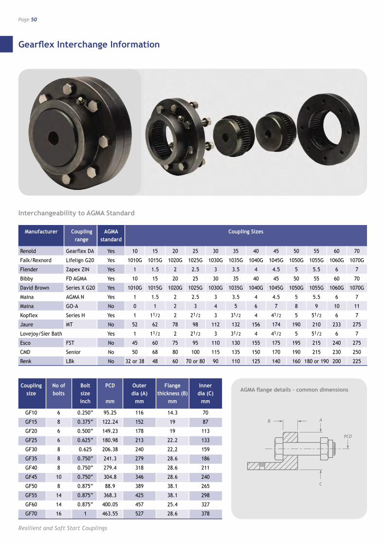
Gearflex Interchange Information
Resilient and Soft Start Couplings
Page 50
Manufacturer Coupling AGMA Coupling Sizes range standard
Renold Gearflex DA Yes 10 15 20 25 30 35 40 45 50 55 60 70
Falk/Rexnord Lifelign G20 Yes 1010G 1015G 1020G 1025G 1030G 1035G 1040G 1045G 1050G 1055G 1060G 1070G
Flender Zapex ZIN Yes 1 1.5 2 2.5 3 3.5 4 4.5 5 5.5 6 7
Bibby FD AGMA Yes 10 15 20 25 30 35 40 45 50 55 60 70
David Brown Series X G20 Yes 1010G 1015G 1020G 1025G 1030G 1035G 1040G 1045G 1050G 1055G 1060G 1070G
Maina AGMA N Yes 1 1.5 2 2.5 3 3.5 4 4.5 5 5.5 6 7
Maina GO-A No 0 1 2 3 4 5 6 7 8 9 10 11
Kopflex Series H Yes 1 11/2 2 21/2 3 31/2 4 41/2 5 51/2 6 7
Jaure MT No 52 62 78 98 112 132 156 174 190 210 233 275
Lovejoy/Sier Bath Yes 1 11/2 2 21/2 3 31/2 4 41/2 5 51/2 6 7
Esco FST No 45 60 75 95 110 130 155 175 195 215 240 275
CMD Senior No 50 68 80 100 115 135 150 170 190 215 230 250
Renk LBk No 32 or 38 48 60 70 or 80 90 110 125 140 160 180 or 190 200 225
Coupling No of Bolt PCD Outer Flange Inner size bolts size dia (A) thickness (B) dia (C) inch mm mm mm mm
GF10 6 0.250” 95.25 116 14.3 70
GF15 8 0.375” 122.24 152 19 87
GF20 6 0.500” 149.23 178 19 113
GF25 6 0.625” 180.98 213 22.2 133
GF30 8 0.625 206.38 240 22,2 159
GF35 8 0.750” 241.3 279 28.6 186
GF40 8 0.750” 279.4 318 28.6 211
GF45 10 0.750” 304.8 346 28.6 240
GF50 8 0.875” 88.9 389 38.1 265
GF55 14 0.875” 368.3 425 38.1 298
GF60 14 0.875” 400.05 457 25.4 327
GF70 16 1 463.55 527 28.6 378
AB
PCD
C
Interchangeability to AGMA Standard
AGMA flange details – common dimensions
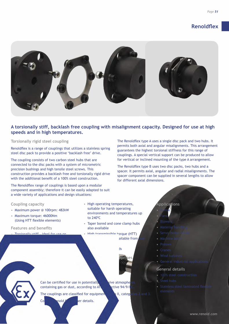
Renoldflex
www.renold.com
Page 51
Torsionally rigid steel coupling
Renoldflex is a range of couplings that utilizes a stainless spring steel disc pack to provide a positive ‘backlash free’ drive.
The coupling consists of two carbon steel hubs that are connected to the disc packs with a system of micrometric precision bushings and high tensile steel screws. This construction provides a backlash free and torsionally rigid drive with the additional benefit of a 100% steel construction.
The Renoldflex range of couplings is based upon a modular component assembly; therefore it can be easily adapted to suit a wide variety of applications and design situations:
The Renoldflex type A uses a single disc pack and two hubs. It permits both axial and angular misalignments. This arrangement guarantees the highest torsional stiffness for this range of couplings. A special vertical support can be produced to allow for vertical or inclined mounting of the type A arrangement.
The Renoldflex type B uses two disc packs, two hubs and a spacer. It permits axial, angular and radial misalignments. The spacer component can be supplied in several lengths to allow for different axial dimensions.
A torsionally stiff, backlash free coupling with misalignment capacity. Designed for use at high speeds and in high temperatures.
Coupling capacity• Maximum power @ 100rpm: 482kW
• Maximum torque: 46000Nm (Using HTT flexible elements)
Features and benefits• Torsionally stiff – ideal for use on
precision machines
• 100% maintenance free – long life with little wear
• Misalignment capabilities allowing flexibility in installation
• Zero backlash guarantees operational accuracy
• High operating temperatures, suitable for harsh operating environments and temperatures up to 240ºC
• Taper bored and cone clamp hubs also available
• High transmissible torque (HTT) flexible elements available from size 70 up
• High operating speeds
Standard range comprises• Shaft to Shaft
• Spacer type
Applications• Pumps
• Fans
• Blowers
• Material handling
• Servo motor drives
• Machine tools
• Presses
• Cranes
• Wind turbines
• General industrial applications
General details• 100% steel construction
• Steel hubs
• Stainless steel laminated flexible elements
Can be certified for use in potentially explosive atmospheres containing gas or dust, according to ATEX directive 94/9/EC.
The couplings are classified for equipment group II, categories 2 and 3.
Contact Renold for further details.
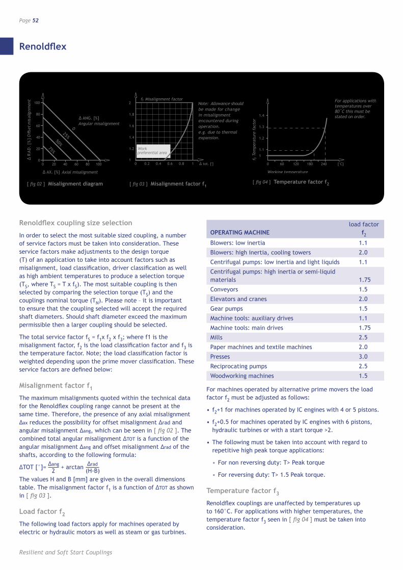
Renoldflex
Resilient and Soft Start Couplings
Page 52
Renoldflex coupling size selection
In order to select the most suitable sized coupling, a number of service factors must be taken into consideration. These service factors make adjustments to the design torque (T) of an application to take into account factors such as misalignment, load classification, driver classification as well as high ambient temperatures to produce a selection torque (TS, where TS = T x fS). The most suitable coupling is then selected by comparing the selection torque (TS) and the couplings nominal torque (TN). Please note – it is important to ensure that the coupling selected will accept the required shaft diameters. Should shaft diameter exceed the maximum permissible then a larger coupling should be selected.
The total service factor fS = f1x f2 x f3; where f1 is the misalignment factor, f2 is the load classification factor and f3 is the temperature factor. Note; the load classification factor is weighted depending upon the prime mover classification. These service factors are defined below:
Misalignment factor f1
The maximum misalignments quoted within the technical data for the Renoldflex coupling range cannot be present at the same time. Therefore, the presence of any axial misalignment ∆ax reduces the possibility for offset misalignment ∆rad and angular misalignment ∆ang, which can be seen in [ fig 02 ]. The combined total angular misalignment ∆TOT is a function of the angular misalignment ∆ang and offset misalignment ∆rad of the shafts, according to the following formula:
∆TOT [°]= ∆ang + arctan ∆rad
The values H and B [mm] are given in the overall dimensions table. The misalignment factor f1 is a function of ∆TOT as shown in [ fig 03 ].
Load factor f2
The following load factors apply for machines operated by electric or hydraulic motors as well as steam or gas turbines.
load factor OPERATING MACHINE f2
Blowers: low inertia 1.1
Blowers: high inertia, cooling towers 2.0
Centrifugal pumps: low inertia and light liquids 1.1
Centrifugal pumps: high inertia or semi-liquid materials 1.75
Conveyors 1.5
Elevators and cranes 2.0
Gear pumps 1.5
Machine tools: auxiliary drives 1.1
Machine tools: main drives 1.75
Mills 2.5
Paper machines and textile machines 2.0
Presses 3.0
Reciprocating pumps 2.5
Woodworking machines 1.5
For machines operated by alternative prime movers the load factor f2 must be adjusted as follows:
• f2+1 for machines operated by IC engines with 4 or 5 pistons.
• f2+0.5 for machines operated by IC engines with 6 pistons, hydraulic turbines or with a start torque >2.
• The following must be taken into account with regard to repetitive high peak torque applications:
• For non reversing duty: T> Peak torque
• For reversing duty: T> 1.5 Peak torque.
Temperature factor f3
Renoldflex couplings are unaffected by temperatures up to 160°C. For applications with higher temperatures, the temperature factor f3 seen in [ fig 04 ] must be taken into consideration.
(H-B)2
100
80
60
40
20
00 20 40 60 80 100
0
%52
%05
%57
∆ ]
%[ .D
AR
tnemngilasi
m tesffO
∆ AX. [%] Axial misalignment
∆ ANG. [%]Angular misalignment
Note: Allowance should be made for changein misalignment encountered during operation. e.g. due to thermalexpansion.
f1 Misalignment factor
0 0.2 0.4 0.6 0.8 11
1.2
1.4
1.6
1.8
2
∆ tot. [°]
Workpreferential area
0 60 120 180 240 [°C]
1
1.1
1.2
1.3
1.4
f 3Te
mpe
ratu
re f
acto
r
Working temperature
For applications withtemperatures over 80˚C this must bestated on order.
[ fig 02 ] Misalignment diagram [ fig 03 ] Misalignment factor f1[ fig 04 ] Temperature factor f2
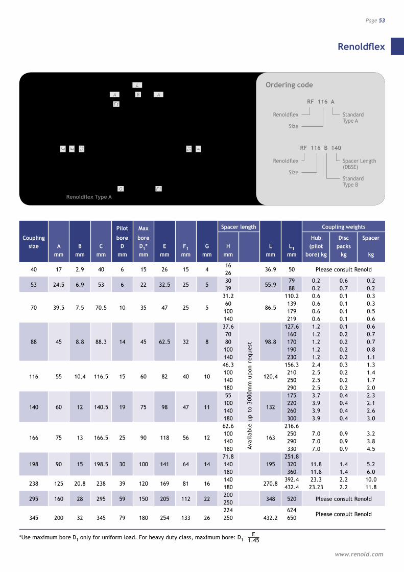
Renoldflex
www.renold.com
Page 53
Pilot Max Spacer length Coupling weights
Coupling bore bore Hub Disc Spacer size A B C D D1* E F1 G H L L1 (pilot packs mm mm mm mm mm mm mm mm mm mm mm bore) kg kg kg
40 17 2.9 40 6 15 26 15 4
16 36.9
50
26
53 24.5 6.9 53 6 22 32.5 25 5 30
55.9 79 0.2 0.6 0.2
39 88 0.2 0.7 0.2 31.2 110.2 0.6 0.1 0.3
70 39.5 7.5 70.5 10 35 47 25 5 60
86.5 139 0.6 0.1 0.3
100 179 0.6 0.1 0.5 140 219 0.6 0.1 0.6 37.6 127.6 1.2 0.1 0.6 70 160 1.2 0.2 0.7 88 45 8.8 88.3 14 45 62.5 32 8 80 98.8 170 1.2 0.2 0.7 100 190 1.2 0.2 0.8 140 230 1.2 0.2 1.1 46.3 156.3 2.4 0.3 1.3
116 55 10.4 116.5 15 60 82 40 10 100
120.4 210 2.5 0.2 1.4
140 250 2.5 0.2 1.7 180 290 2.5 0.2 2.0 55 175 3.7 0.4 2.3
140 60 12 140.5 19 75 98 47 11 100
132 220 3.9 0.4 2.1
140 260 3.9 0.4 2.6 180 300 3.9 0.4 3.0 62.6 216.6
166 75 13 166.5 25 90 118 56 12 100
163 250 7.0 0.9 3.2
140 290 7.0 0.9 3.8 180 330 7.0 0.9 4.5 71.8 251.8 198 90 15 198.5 30 100 141 64 14 140 195 320 11.8 1.4 5.2 180 360 11.8 1.4 6.0
238 125 20.8 238 39 120 169 81 16 140
270.8 392.4 23.3 2.2 10.0
180 432.4 23.23 2.2 11.8
295 160 28 295 59 150 205 112 22 200
348
520 250 224 624 345 200 32 345 79 180 254 133 26 250 432.2 650
Avai
lab
le u
p t
o 30
00m
m u
pon
req
uest
*Use maximum bore D1 only for uniform load. For heavy duty class, maximum bore: D1= 1.45E
EC
L
F1
A B A
D1
F1G1
D E
B
L1
1DEC
F1
A H AB
F G
1D E
F1
B
L1
1DEC
F1
A H A
GG
B
1D E
L
A B
F1
A
D1EC D1 E
G F1
Renoldflex Type A
Ordering code
RF 116 A
Renoldflex
Size
Standard Type A
RF 116 B 140
Renoldflex
Size
Spacer Length (DBSE)
Standard Type B
Please consult Renold
Please consult Renold
Please consult Renold
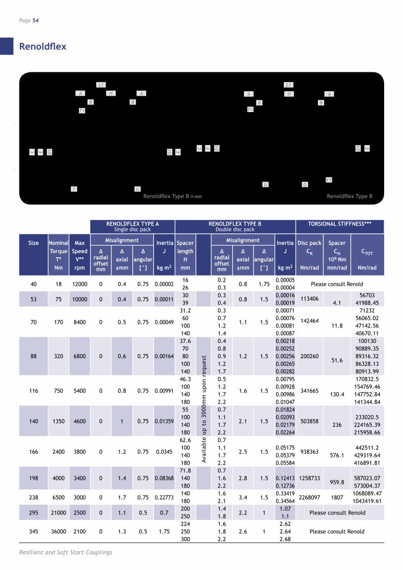
Renoldflex
Resilient and Soft Start Couplings
Page 54
RENOLDFLEX TYPE A Single disc pack
RENOLDFLEX TYPE B Double disc pack
TORSIONAL STIFFNESS***
Size Nominal Max Misalignment Inertia Spacer Misalignment Inertia Disc pack Spacer Torque Speed Δ Δ Δ J length Δ Δ Δ J CK CH CTOT T* V** radial axial angular H radial axial angular 106 Nm Nm rpm
offset ±mm [°] kg m2 mm
offset ±mm [°] kg m2 Nm/rad mm/rad Nm/rad mm mm
40 18 12000 0 0.4 0.75 0.00002 16 0.2
0.8 1.75 0.00005
Please consult Renold 26 0.3 0.00004
53 75 10000 0 0.4 0.75 0.00011 30 0.3
0.8 1.5 0.00016 113406 56703
39 0.4 0.00019 4.1 41988.45 31.2 0.3 0.00071 71232
70 170 8400 0 0.5 0.75 0.00049 60 0.7
1.1 1.5 0.00076 142464 56065.02
100 1.2 0.00081 11.8 47142.56 140 1.4 0.00087 40670.11 37.6 0.4 0.00218 100130 70 0.8 0.00252 90889.35 88 320 6800 0 0.6 0.75 0.00164 80 0.9 1.2 1.5 0.00256 200260
51.6 89316.32
100 1.2 0.00265 86328.13 140 1.7 0.00282 80913.99 46.3 0.5 0.00795 170832.5
116 750 5400 0 0.8 0.75 0.00991 100 1.2
1.6 1.5 0.00928
341665 154769.46
140 1.7 0.00986 130.4 147752.84 180 2.2 0.01047 141344.84 55 0.7 0.01824
140 1350 4600 0 1 0.75 0.01359 100 1.1
2.1 1.5 0.02093
503858 233020.5
140 1.7 0.02179 236 224165.39 180 2.2 0.02264 215958.66 62.6 0.7
166 2400 3800 0 1.2 0.75 0.0345 100 1.1
2.5 1.5 0.05175
938363 442511.2
140 1.7 0.05379 576.1 429319.64 180 2.2 0.05584 416891.81 71.8 0.7 198 4000 3400 0 1.4 0.75 0.08368 140 1.6 2.8 1.5 0.12413 1258733
959.8 587023.07
180 2.2 0.12736 573004.37
238 6500 3000 0 1.7 0.75 0.22773 140 1.6
3.4 1.5 0.33419
2268097 1807 1068089.47
180 2.1 0.34564 1043419.61
295 21000 2500 0 1.1 0.5 0.7 200 1.4
2.2 1 1.07
Please consult Renold 250 1.8 1.1 224 1.6 2.62 345 36000 2100 0 1.3 0.5 1.75 250 1.8 2.6 1 2.64 Please consult Renold 300 2.2 2.68
Avai
lab
le u
p t
o 30
00m
m u
pon
req
uest
EC
L
F1
A B A
D1
F1G
1D E
B
L1
1DEC
F1
A H AB
F G
1D E
F1
B
L1
1DEC
F1
A H A
GG
B
1D E
L1
B
A H
B
F1
D1EC D1 E
GF
A
D1EC
L1
B
A H
F1
G GF1
B
A
D1 E
Renoldflex Type B H-MIN Renoldflex Type B
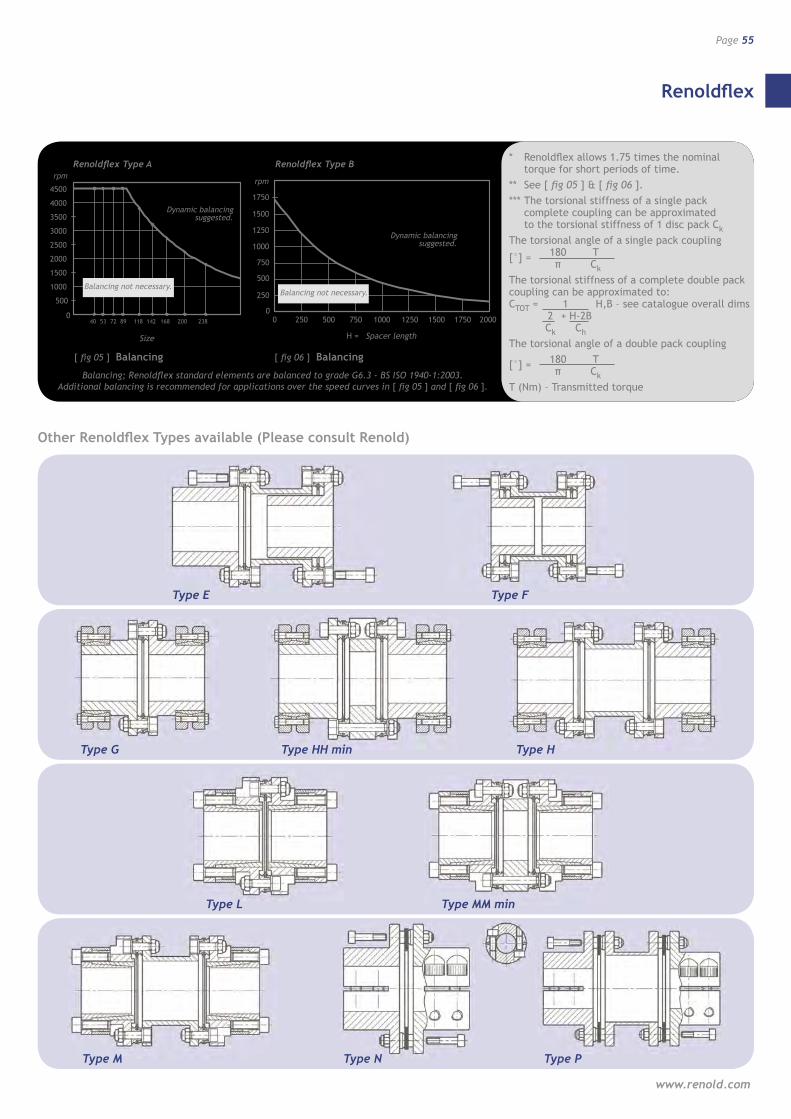
Renoldflex
www.renold.com
Page 55
* Renoldflex allows 1.75 times the nominal torque for short periods of time.
** See [ fig 05 ] & [ fig 06 ]. *** The torsional stiffness of a single pack
complete coupling can be approximated to the torsional stiffness of 1 disc pack Ck
The torsional angle of a single pack coupling
[°] = 180 T π Ck
The torsional stiffness of a complete double pack coupling can be approximated to: CTOT = 1 H,B – see catalogue overall dims 2 + H-2B Ck Ch
The torsional angle of a double pack coupling
[°] = 180 T π Ck
T (Nm) – Transmitted torque
H = Spacer length
rpm
0
250
500
1000
1500
1750
1250
750
0
Dynamic balancingsuggested.
Balancing not necessary.
250 500 750 1000 1250 1500 1750 2000
Size
0
4500
4000
3500
3000
2500
2000
1500
1000
500
40 72 89 118 142 168 200 23853
rpm
Balancing not necessary.
Dynamic balancingsuggested.
Balancing; Renoldflex standard elements are balanced to grade G6.3 - BS ISO 1940-1:2003. Additional balancing is recommended for applications over the speed curves in [ fig 05 ] and [ fig 06 ].
[ fig 05 ] Balancing
Renoldflex Type A
[ fig 06 ] Balancing
Renoldflex Type B
Type E Type F
Type G Type HH min
Type L Type MM min
Type M Type P
Type H
Type N
Other Renoldflex Types available (Please consult Renold)
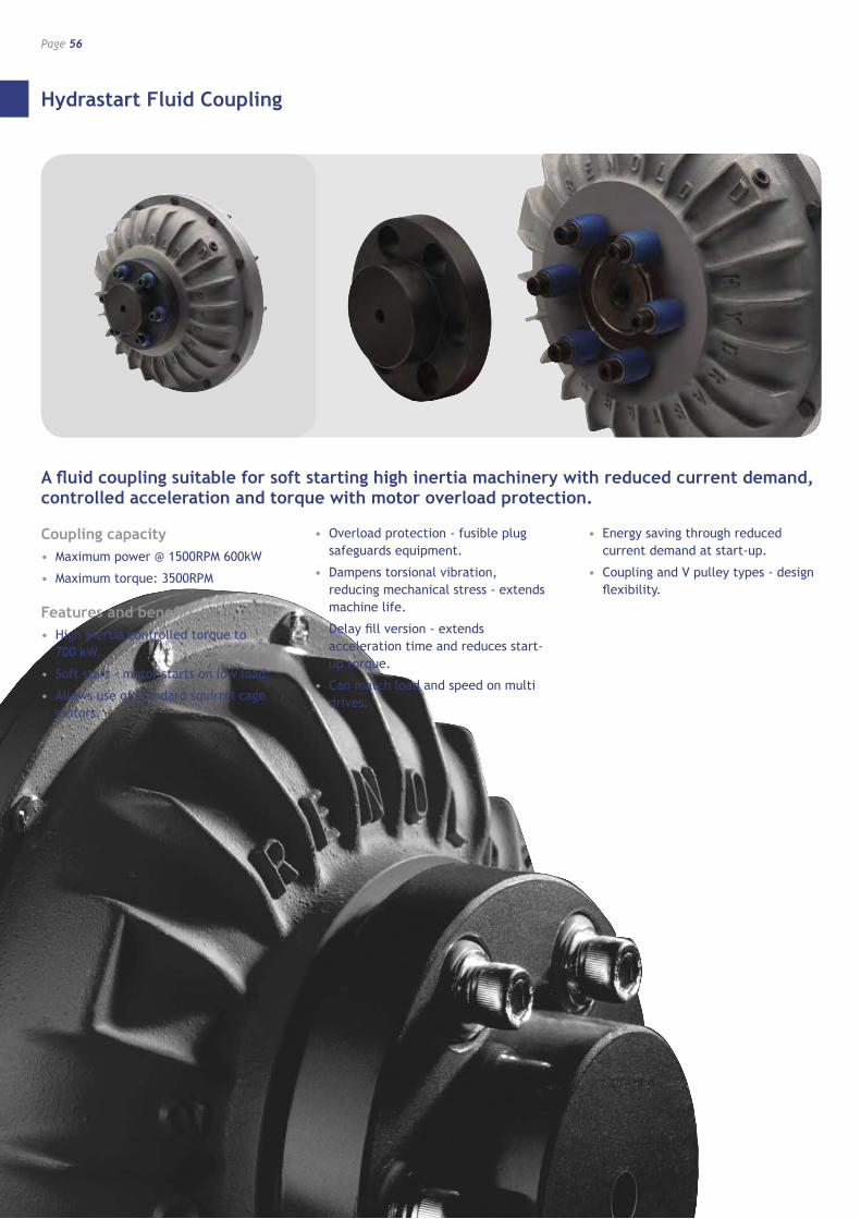
Hydrastart Fluid Coupling
Resilient and Soft Start Couplings
Page 56
A fluid coupling suitable for soft starting high inertia machinery with reduced current demand, controlled acceleration and torque with motor overload protection.
Coupling capacity• Maximum power @ 1500RPM 600kW
• Maximum torque: 3500RPM
Features and benefits• High inertia controlled torque to
700 kW.
• Soft start - motor starts on low load.
• Allows use of standard squirrel cage motors.
• Overload protection - fusible plug safeguards equipment.
• Dampens torsional vibration, reducing mechanical stress - extends machine life.
• Delay fill version - extends acceleration time and reduces start-up torque.
• Can match load and speed on multi drives.
• Energy saving through reduced current demand at start-up.
• Coupling and V pulley types - design flexibility.
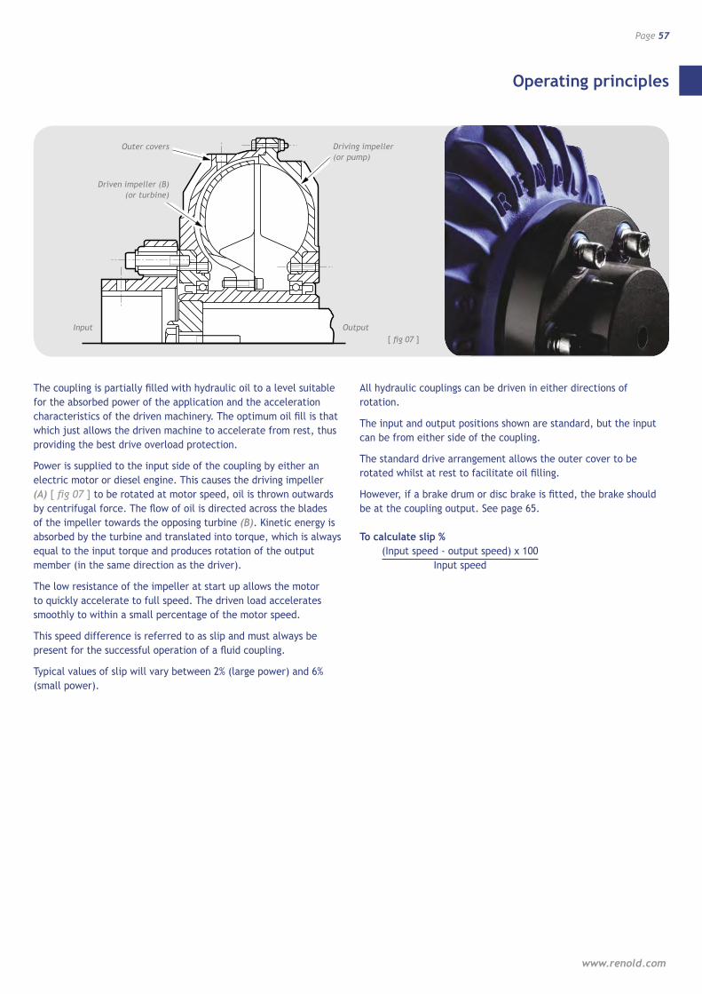
Operating principles
www.renold.com
Page 57
DRIVEN IMPELLER (B)�(OR TURBINE)
DRIVING IMPELLER (A)�(OR PUMP)
OUTER COVERS
INPUT OUTPUT
The coupling is partially filled with hydraulic oil to a level suitable for the absorbed power of the application and the acceleration characteristics of the driven machinery. The optimum oil fill is that which just allows the driven machine to accelerate from rest, thus providing the best drive overload protection.
Power is supplied to the input side of the coupling by either an electric motor or diesel engine. This causes the driving impeller (A) [ fig 07 ] to be rotated at motor speed, oil is thrown outwards by centrifugal force. The flow of oil is directed across the blades of the impeller towards the opposing turbine (B). Kinetic energy is absorbed by the turbine and translated into torque, which is always equal to the input torque and produces rotation of the output member (in the same direction as the driver).
The low resistance of the impeller at start up allows the motor to quickly accelerate to full speed. The driven load accelerates smoothly to within a small percentage of the motor speed.
This speed difference is referred to as slip and must always be present for the successful operation of a fluid coupling.
Typical values of slip will vary between 2% (large power) and 6% (small power).
All hydraulic couplings can be driven in either directions of rotation.
The input and output positions shown are standard, but the input can be from either side of the coupling.
The standard drive arrangement allows the outer cover to be rotated whilst at rest to facilitate oil filling.
However, if a brake drum or disc brake is fitted, the brake should be at the coupling output. See page 65.
To calculate slip % (Input speed - output speed) x 100 Input speed
Outer covers
Driven impeller (B) (or turbine)
Input Output
Driving impeller (or pump)
[ fig 07 ]
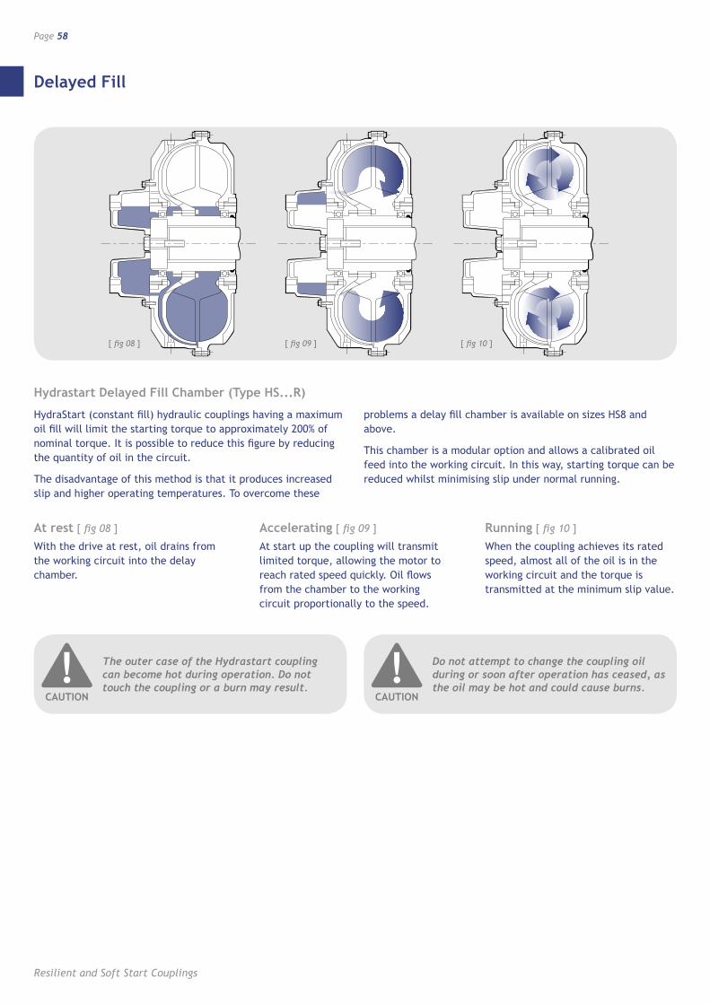
Delayed Fill
Resilient and Soft Start Couplings
Page 58
Hydrastart Delayed Fill Chamber (Type HS...R)
HydraStart (constant fill) hydraulic couplings having a maximum oil fill will limit the starting torque to approximately 200% of nominal torque. It is possible to reduce this figure by reducing the quantity of oil in the circuit.
The disadvantage of this method is that it produces increased slip and higher operating temperatures. To overcome these
problems a delay fill chamber is available on sizes HS8 and above.
This chamber is a modular option and allows a calibrated oil feed into the working circuit. In this way, starting torque can be reduced whilst minimising slip under normal running.
[ fig 08 ]
At rest [ fig 08 ]
With the drive at rest, oil drains from the working circuit into the delay chamber.
Accelerating [ fig 09 ]
At start up the coupling will transmit limited torque, allowing the motor to reach rated speed quickly. Oil flows from the chamber to the working circuit proportionally to the speed.
Running [ fig 10 ]
When the coupling achieves its rated speed, almost all of the oil is in the working circuit and the torque is transmitted at the minimum slip value.
[ fig 09 ] [ fig 10 ]
The outer case of the Hydrastart coupling can become hot during operation. Do not touch the coupling or a burn may result.
!CAUTION
Do not attempt to change the coupling oil during or soon after operation has ceased, as the oil may be hot and could cause burns.
!CAUTION
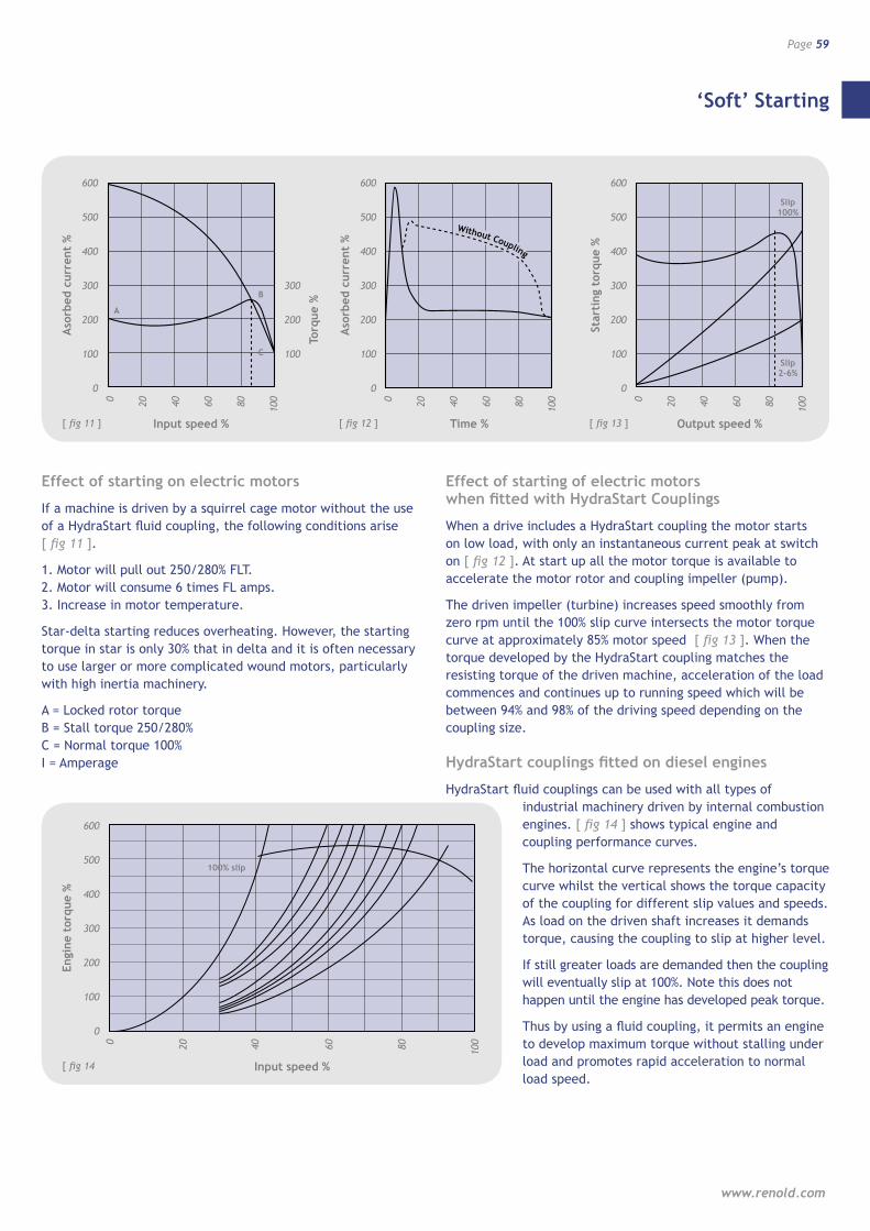
‘Soft’ Starting
www.renold.com
Page 59
Effect of starting on electric motors
If a machine is driven by a squirrel cage motor without the use of a HydraStart fluid coupling, the following conditions arise [ fig 11 ].
1. Motor will pull out 250/280% FLT.2. Motor will consume 6 times FL amps.3. Increase in motor temperature.
Star-delta starting reduces overheating. However, the starting torque in star is only 30% that in delta and it is often necessary to use larger or more complicated wound motors, particularly with high inertia machinery.
A = Locked rotor torqueB = Stall torque 250/280%C = Normal torque 100%I = Amperage
Effect of starting of electric motors when fitted with HydraStart Couplings
When a drive includes a HydraStart coupling the motor starts on low load, with only an instantaneous current peak at switch on [ fig 12 ]. At start up all the motor torque is available to accelerate the motor rotor and coupling impeller (pump).
The driven impeller (turbine) increases speed smoothly from zero rpm until the 100% slip curve intersects the motor torque curve at approximately 85% motor speed [ fig 13 ]. When the torque developed by the HydraStart coupling matches the resisting torque of the driven machine, acceleration of the load commences and continues up to running speed which will be between 94% and 98% of the driving speed depending on the coupling size.
HydraStart couplings fitted on diesel engines
HydraStart fluid couplings can be used with all types of industrial machinery driven by internal combustion
engines. [ fig 14 ] shows typical engine and coupling performance curves.
The horizontal curve represents the engine’s torque curve whilst the vertical shows the torque capacity of the coupling for different slip values and speeds. As load on the driven shaft increases it demands torque, causing the coupling to slip at higher level.
If still greater loads are demanded then the coupling will eventually slip at 100%. Note this does not happen until the engine has developed peak torque.
Thus by using a fluid coupling, it permits an engine to develop maximum torque without stalling under load and promotes rapid acceleration to normal load speed.
Without Coupling
Without Coupling
[ fig 11 ]
0
Aso
rbed
cur
rent
%
600
500
400
300
200
100
A
B
C
0 20 40 60 80 100
Input speed % [ fig 12 ]
0
Aso
rbed
cur
rent
%
600
500
400
300
200
100
0 20 40 60 80 100
Time % [ fig 13 ]
0
Star
ting
tor
que
%
600
500
400
300
200
100
Slip 100%
Slip 2-6%
0 20 40 60 80 100
Output speed %
[ fig 14
0
Engi
ne t
orqu
e %
600
500
400
300
200
100
100% slip
0
Input speed %
20 40 60 80 100
Torq
ue %
300
200
100
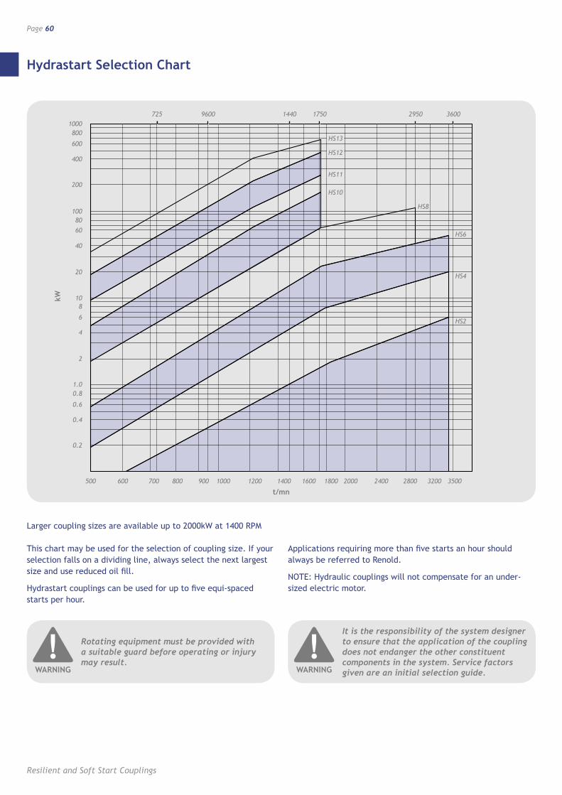
Hydrastart Selection Chart
Resilient and Soft Start Couplings
Page 60
Larger coupling sizes are available up to 2000kW at 1400 RPM
This chart may be used for the selection of coupling size. If your selection falls on a dividing line, always select the next largest size and use reduced oil fill.
Hydrastart couplings can be used for up to five equi-spaced starts per hour.
Applications requiring more than five starts an hour should always be referred to Renold.
NOTE: Hydraulic couplings will not compensate for an under-sized electric motor.
Rotating equipment must be provided with a suitable guard before operating or injury may result.
!WARNING
It is the responsibility of the system designer to ensure that the application of the coupling does not endanger the other constituent components in the system. Service factors given are an initial selection guide.
!WARNING
0.2
0.4
0.6
0.81.0
2
4
6
810
20
40
60
80100
200
400
600
8001000
725 9600 17501440 36002950
500 600 700 800 900 1000 1200 1400 1600 1800 2000 2400 2800 3200 3500
t/mn
kW
HS13
HS12
HS11
HS10
HS8
HS6
HS4
HS2
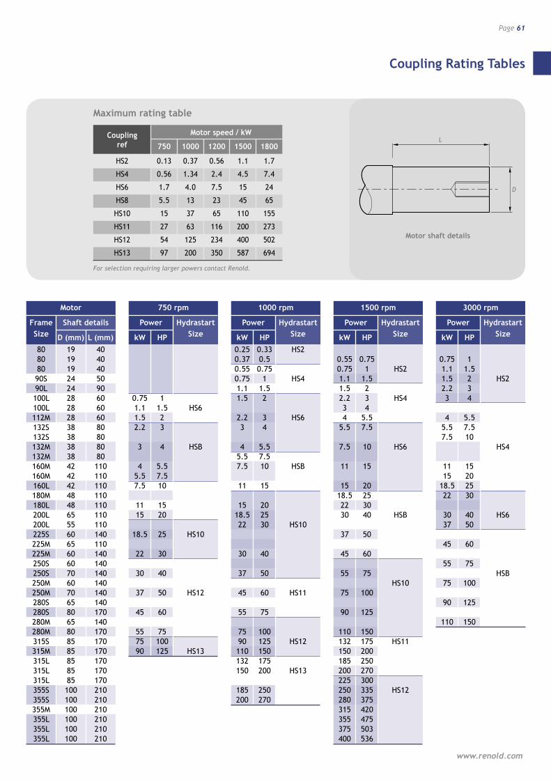
Coupling Rating Tables
www.renold.com
Page 61
Motor shaft details
L
D
L
D
Motor
Frame Shaft details
Size D (mm) L (mm) 80 19 40 80 19 40 80 19 40 90S 24 50 90L 24 90 100L 28 60 100L 28 60 112M 28 60 132S 38 80 132S 38 80 132M 38 80 132M 38 80 160M 42 110 160M 42 110 160L 42 110 180M 48 110 180L 48 110 200L 65 110 200L 55 110 225S 60 140 225M 65 110 225M 60 140 250S 60 140 250S 70 140 250M 60 140 250M 70 140 280S 65 140 280S 80 170 280M 65 140 280M 80 170 315S 85 170 315M 85 170 315L 85 170 315L 85 170 315L 85 170 355S 100 210 355S 100 210 355M 100 210 355L 100 210 355L 100 210 355L 100 210
750 rpm
Power Hydrastart
kW HP Size
0.75 1 1.1 1.5 HS6 1.5 2 2.2 3 3 4 HSB 4 5.5 5.5 7.5 7.5 10 11 15 15 20 18.5 25 HS10 22 30 30 40 37 50 HS12 45 60 55 75 75 100 90 125 HS13
1000 rpm
Power Hydrastart
kW HP Size
0.25 0.33 HS2 0.37 0.5 0.55 0.75 0.75 1 HS4 1.1 1.5 1.5 2 2.2 3 HS6 3 4 4 5.5 5.5 7.5 7.5 10 HSB 11 15 15 20 18.5 25 22 30 HS10 30 40 37 50 45 60 HS11 55 75 75 100 90 125 HS12 110 150 132 175 150 200 HS13 185 250 200 270
1500 rpm
Power Hydrastart
kW HP Size
0.55 0.75 0.75 1 HS2 1.1 1.5 1.5 2 2.2 3 HS4 3 4 4 5.5 5.5 7.5 7.5 10 HS6 11 15 15 20 18.5 25 22 30 30 40 HSB 37 50 45 60 55 75 HS10 75 100 90 125 110 150 132 175 HS11 150 200 185 250 200 270 225 300 250 335 HS12 280 375 315 420 355 475 375 503 400 536
3000 rpm
Power Hydrastart
kW HP Size
0.75 1 1.1 1.5 1.5 2 HS2 2.2 3 3 4 4 5.5 5.5 7.5 7.5 10 HS4 11 15 15 20 18.5 25 22 30 30 40 HS6 37 50 45 60 55 75 HSB 75 100 90 125 110 150
Coupling Motor speed / kW
ref 750 1000 1200 1500 1800
HS2 0.13 0.37 0.56 1.1 1.7
HS4 0.56 1.34 2.4 4.5 7.4
HS6 1.7 4.0 7.5 15 24
HS8 5.5 13 23 45 65
HS10 15 37 65 110 155
HS11 27 63 116 200 273
HS12 54 125 234 400 502
HS13 97 200 350 587 694
For selection requiring larger powers contact Renold.
Maximum rating table
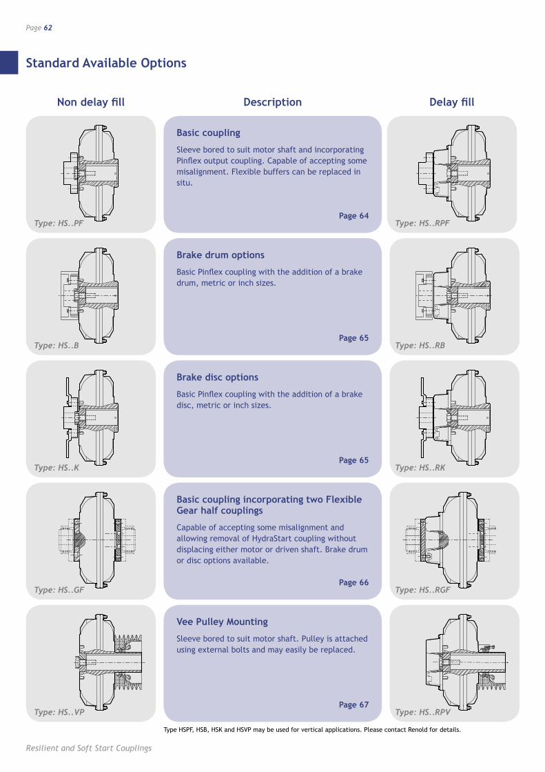
Standard Available Options
Resilient and Soft Start Couplings
Page 62
Non delay fill
Type: HS..PF
Delay fillDescription
Type: HS..B
Type: HS..K
Type: HS..GF
Type: HS..VP
Type: HS..RPF
Type: HS..RB
Type: HS..RK
Type: HS..RGF
Type: HS..RPV
Basic coupling
Sleeve bored to suit motor shaft and incorporating Pinflex output coupling. Capable of accepting some misalignment. Flexible buffers can be replaced in situ.
Page 64
Brake drum options
Basic Pinflex coupling with the addition of a brake drum, metric or inch sizes.
Page 65
Brake disc options
Basic Pinflex coupling with the addition of a brake disc, metric or inch sizes.
Page 65
Basic coupling incorporating two Flexible Gear half couplings
Capable of accepting some misalignment and allowing removal of HydraStart coupling without displacing either motor or driven shaft. Brake drum or disc options available.
Page 66
Vee Pulley Mounting
Sleeve bored to suit motor shaft. Pulley is attached using external bolts and may easily be replaced.
Page 67
Type HSPF, HSB, HSK and HSVP may be used for vertical applications. Please contact Renold for details.

Overload Protection
www.renold.com
Page 63
When a hydraulic coupling experiences overload there is acorrespondingly high slip value accompanied by a rise in the oiltemperature. To prevent damage to the drive there are threeoptions available.
1. Fusible plug
This is fitted as standard on all HydraStart couplings sizes 4 and above. The standard plug is set to fuse at 138°C. Another option available allows fusing at 183°C. Because oil is discharged when the plug fuses it is advisable to correctly guard couplings using this type of device.
2. Thermal trigger
Fitted as an option on HydraStart couplings sizes 6 and above, this device prevents oil being discharged from the coupling at overload. As with the fusible plug, two melt temperatures are offered. When melt point is reached a pin is released which engages with a limit switch. The signal from this switch can operate an alarm or switch off the electric motor to protect the drive. After the cause of the overload has been removed the drive can be restarted after replacing the thermal trigger.
3. Non-contact sensor
Non-contact speed and heat sensors can be supplied which shut down the drive in the event of overload. Please contact Renold for more information.
HydraStart thermal trigger
Operating principles
This device will trigger the limit switch if the oil temperature reaches a predetermined level without loss of oil from the coupling. Fusible trigger plug 117°C alternatively 138°C.
Electrical characteristics
2-Pole 1N/C + 1N/O, conforms to IEC 529 IP 66, contact type XCK rating 500V AC-15
3-20mm ISO Cable Entries.
16
L1L8
32
2
50.8
41.0
110
144
18.528
Size A L Li
HS6 345 93.7 21.5
HS8 422 123.2 20.0
HS10 511 146.1 16.0
HS11 580 144.5 10.5
HS12 669 173.3 10.5
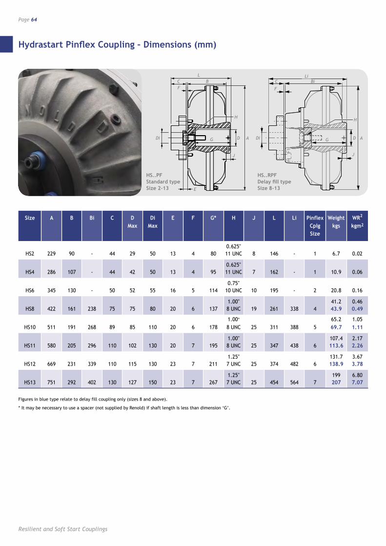
Hydrastart Pinflex Coupling – Dimensions (mm)
Resilient and Soft Start Couplings
Page 64
F
L
G
C B
Di
E
J
D A
H
F
Li
G
C Bi
Di
J
D A
H
HS..PF Standard type Size 2-13
HS..RPF Delay fill type Size 8-13
Figures in blue type relate to delay fill coupling only (sizes 8 and above).
* It may be necessary to use a spacer (not supplied by Renold) if shaft length is less than dimension ‘G’.
Size A B Bi C D Di E F G* H J L Li Pinflex Weight WR2
Max Max Cplg kgs kgm2
Size
0.625" HS2 229 90 - 44 29 50 13 4 80 11 UNC 8 146 - 1 6.7 0.02
0.625" HS4 286 107 - 44 42 50 13 4 95 11 UNC 7 162 - 1 10.9 0.06
0.75" HS6 345 130 - 50 52 55 16 5 114 10 UNC 10 195 - 2 20.8 0.16
1.00" 41.2 0.46 HS8 422 161 238 75 75 80 20 6 137 8 UNC 19 261 338 4 43.9 0.49
1.00" 65.2 1.05 HS10 511 191 268 89 85 110 20 6 178 8 UNC 25 311 388 5 69.7 1.11
1.00" 107.4 2.17 HS11 580 205 296 110 102 130 20 7 195 8 UNC 25 347 438 6 113.6 2.26
1.25" 131.7 3.67 HS12 669 231 339 110 115 130 23 7 211 7 UNC 25 374 482 6 138.9 3.78
1.25" 199 6.80 HS13 751 292 402 130 127 150 23 7 267 7 UNC 25 454 564 7 207 7.07
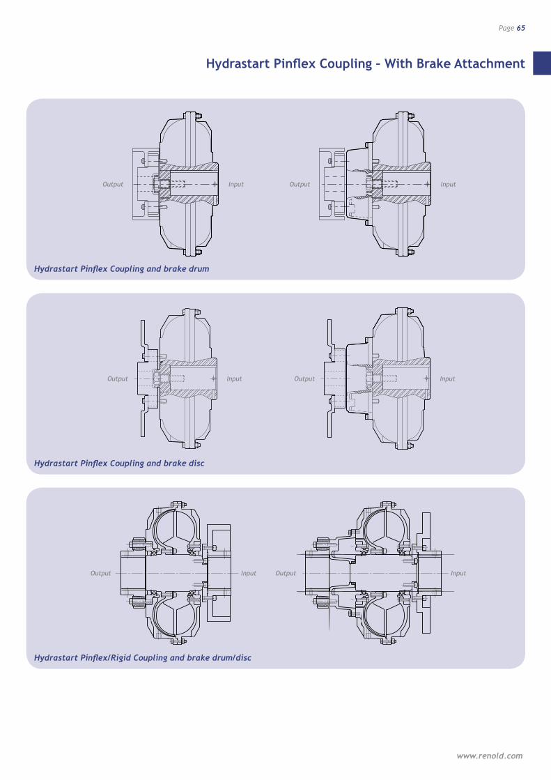
Hydrastart Pinflex Coupling – With Brake Attachment
www.renold.com
Page 65
Hydrastart Pinflex Coupling and brake drum
Hydrastart Pinflex Coupling and brake disc
Hydrastart Pinflex/Rigid Coupling and brake drum/disc
Output Input Output Input
Output Input Output Input
Output Input Output Input
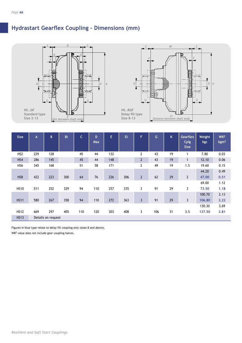
Hydrastart Gearflex Coupling – Dimensions (mm)
Resilient and Soft Start Couplings
Page 66
Figures in blue type relate to delay fill coupling only (sizes 8 and above).
WR2 value does not include gear coupling halves.
Size A B Bi C D E Ei F G K Gearflex Weight WR2
Max Cplg kgs kgm2
Size
HS2 229 128 45 44 132 2 43 19 1 7.80 0.03
HS4 286 145 45 44 148 2 43 19 1 12.10 0.06
HS6 345 168 51 58 171 2 49 19 1.5 19.60 0.15
44.20 0.49
HS8 422 223 300 64 76 226 306 2 62 29 2 47.00 0.51
69.00 1.12
HS10 511 252 329 94 110 257 335 3 91 29 3 73.50 1.18
100.70 2.13
HS11 580 267 358 94 110 272 363 3 91 29 3 106.80 2.22
130.30 3.69
HS12 669 297 405 110 120 303 408 3 106 31 3.5 137.50 3.81
HS13 Details on request
F
G
C Bi
D D A
C
F
G
Ei Distance between shaft ends
HS..RGF Delay fill type Size 8-13
�
�
��
�
�
�
�
� �
� �
����������������������������
F
G
C B
D D A
HS..GF Standard type Size 2-13
C
F
K K
G
E Dist between shaft ends
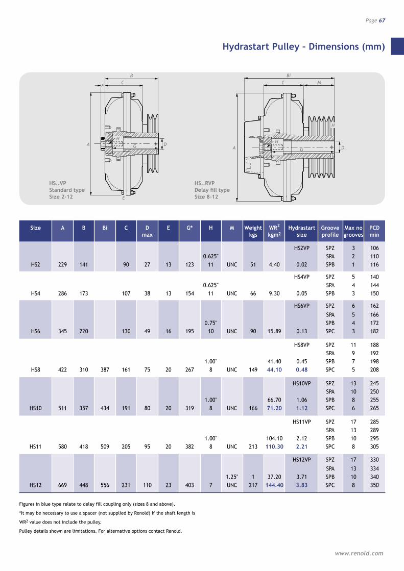
Hydrastart Pulley – Dimensions (mm)
www.renold.com
Page 67
�
�
E
G
CB
A
E
DH
HS..VP Standard type Size 2-12
Figures in blue type relate to delay fill coupling only (sizes 8 and above).
*It may be necessary to use a spacer (not supplied by Renold) if the shaft length is
WR2 value does not include the pulley.
Pulley details shown are limitations. For alternative options contact Renold.
Size A B Bi C D E G* H M Weight WR2 Hydrastart Groove Max no PCD max kgs kgm2 size profile grooves min
HS2VP SPZ 3 106 0.625" SPA 2 110 HS2 229 141 90 27 13 123 11 UNC 51 4.40 0.02 SPB 1 116
HS4VP SPZ 5 140 0.625" SPA 4 144 HS4 286 173 107 38 13 154 11 UNC 66 9.30 0.05 SPB 3 150
HS6VP SPZ 6 162
SPA 5 166 0.75" SPB 4 172 HS6 345 220 130 49 16 195 10 UNC 90 15.89 0.13 SPC 3 182
HS8VP SPZ 11 188 SPA 9 192 1.00" 41.40 0.45 SPB 7 198 HS8 422 310 387 161 75 20 267 8 UNC 149 44.10 0.48 SPC 5 208
HS10VP SPZ 13 245 SPA 10 250 1.00" 66.70 1.06 SPB 8 255 HS10 511 357 434 191 80 20 319 8 UNC 166 71.20 1.12 SPC 6 265
HS11VP SPZ 17 285 SPA 13 289 1.00" 104.10 2.12 SPB 10 295 HS11 580 418 509 205 95 20 382 8 UNC 213 110.30 2.21 SPC 8 305
HS12VP SPZ 17 330
SPA 13 334 1.25" 1 37.20 3.71 SPB 10 340 HS12 669 448 556 231 110 23 403 7 UNC 217 144.40 3.83 SPC 8 350
G
CBi
A D
H
HS..RVP Delay fill type Size 8-12
M
H
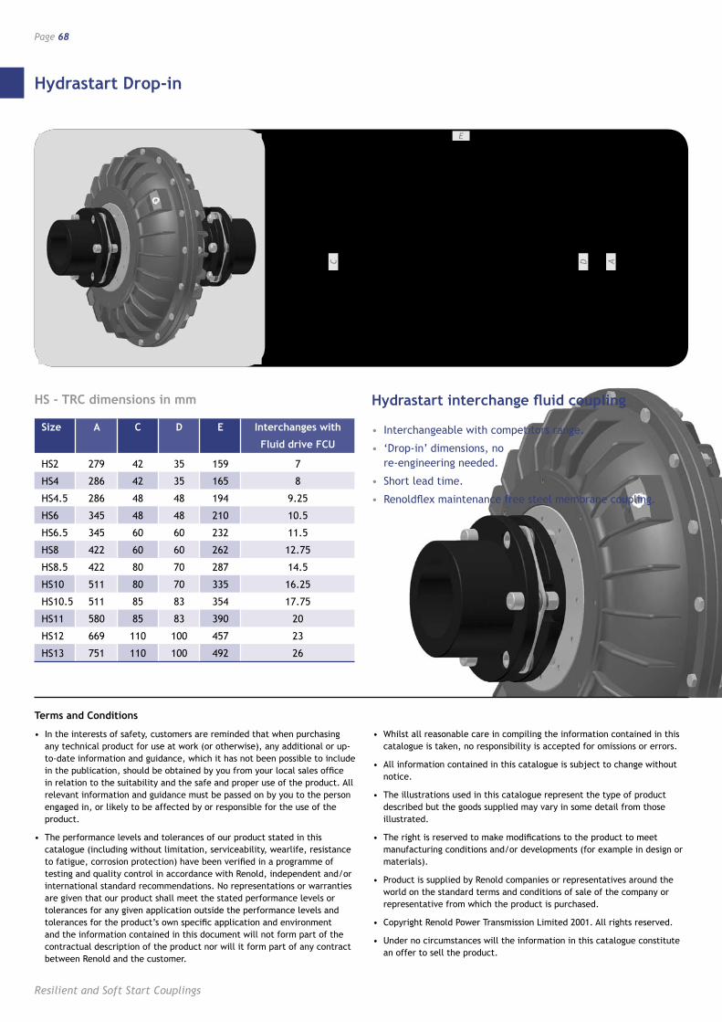
Hydrastart Drop-in
Resilient and Soft Start Couplings
Page 68
E
C AD
Hydrastart interchange fluid coupling
• Interchangeable with competitors range.
• ‘Drop-in’ dimensions, no re-engineering needed.
• Short lead time.
• Renoldflex maintenance free steel membrane coupling.
HS - TRC dimensions in mm
Size A C D E Interchanges with
Fluid drive FCU
HS2 279 42 35 159 7
HS4 286 42 35 165 8
HS4.5 286 48 48 194 9.25
HS6 345 48 48 210 10.5
HS6.5 345 60 60 232 11.5
HS8 422 60 60 262 12.75
HS8.5 422 80 70 287 14.5
HS10 511 80 70 335 16.25
HS10.5 511 85 83 354 17.75
HS11 580 85 83 390 20
HS12 669 110 100 457 23
HS13 751 110 100 492 26
Terms and Conditions
• In the interests of safety, customers are reminded that when purchasing any technical product for use at work (or otherwise), any additional or up-to-date information and guidance, which it has not been possible to include in the publication, should be obtained by you from your local sales office in relation to the suitability and the safe and proper use of the product. All relevant information and guidance must be passed on by you to the person engaged in, or likely to be affected by or responsible for the use of the product.
• The performance levels and tolerances of our product stated in this catalogue (including without limitation, serviceability, wearlife, resistance to fatigue, corrosion protection) have been verified in a programme of testing and quality control in accordance with Renold, independent and/or international standard recommendations. No representations or warranties are given that our product shall meet the stated performance levels or tolerances for any given application outside the performance levels and tolerances for the product’s own specific application and environment and the information contained in this document will not form part of the contractual description of the product nor will it form part of any contract between Renold and the customer.
• Whilst all reasonable care in compiling the information contained in this catalogue is taken, no responsibility is accepted for omissions or errors.
• All information contained in this catalogue is subject to change without notice.
• The illustrations used in this catalogue represent the type of product described but the goods supplied may vary in some detail from those illustrated.
• The right is reserved to make modifications to the product to meet manufacturing conditions and/or developments (for example in design or materials).
• Product is supplied by Renold companies or representatives around the world on the standard terms and conditions of sale of the company or representative from which the product is purchased.
• Copyright Renold Power Transmission Limited 2001. All rights reserved.
• Under no circumstances will the information in this catalogue constitute an offer to sell the product.
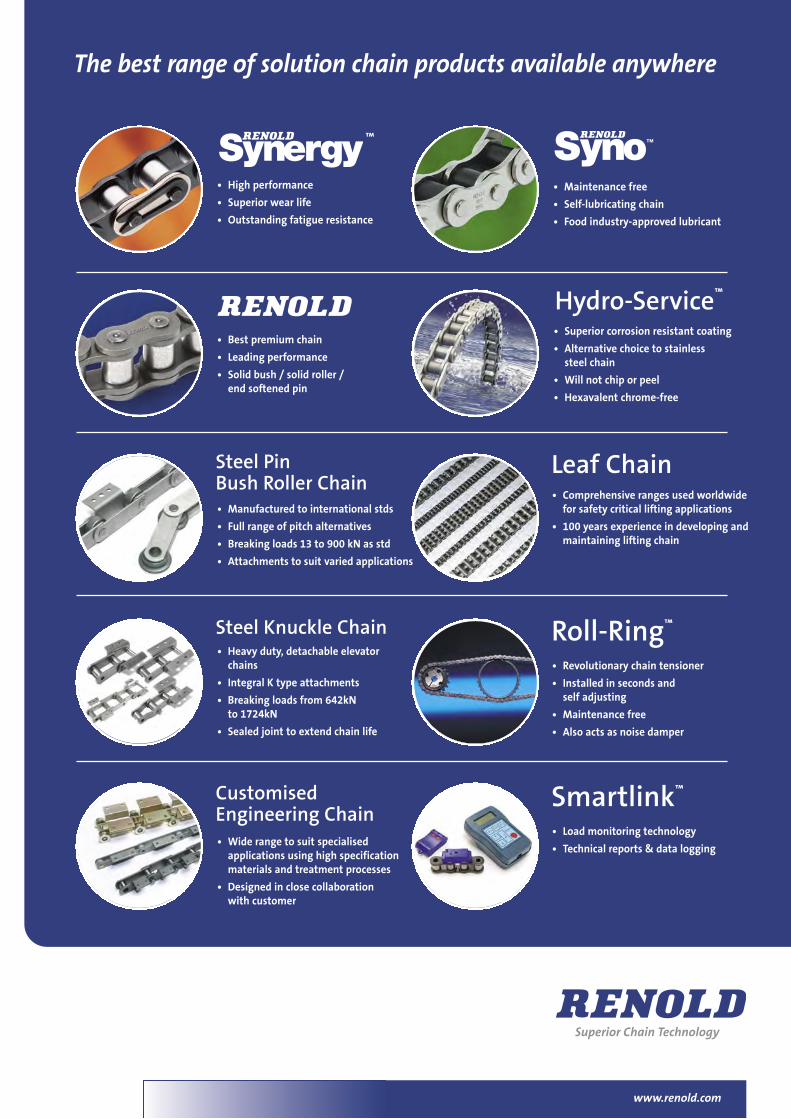
• High performance
• Superior wear life
• Outstanding fatigue resistance
• Best premium chain
• Leading performance
• Solid bush / solid roller /end softened pin
• Manufactured to international stds
• Full range of pitch alternatives
• Breaking loads 13 to 900 kN as std
• Attachments to suit varied applications
• Superior corrosion resistant coating
• Alternative choice to stainlesssteel chain
• Will not chip or peel
• Hexavalent chrome-free
• Comprehensive ranges used worldwidefor safety critical lifting applications
• 100 years experience in developing andmaintaining lifting chain
Hydro-Service™
Leaf Chain
™
www.renold.com
• Heavy duty, detachable elevatorchains
• Integral K type attachments
• Breaking loads from 642kNto 1724kN
• Sealed joint to extend chain life
• Wide range to suit specialisedapplications using high specificationmaterials and treatment processes
• Designed in close collaborationwith customer
• Revolutionary chain tensioner
• Installed in seconds andself adjusting
• Maintenance free
• Also acts as noise damper
Roll-Ring™
• Load monitoring technology
• Technical reports & data logging
Smartlink™
Steel PinBush Roller Chain
Steel Knuckle Chain
CustomisedEngineering Chain
The best range of solution chain products available anywhere
• Maintenance free
• Self-lubricating chain
• Food industry-approved lubricant
36073 A4 1pp chain overview.qxd:A4 30/6/10 13:09 Page 1
www.renold.com
AUSTRALIA Melbourne (Victoria) Tel + 61 (03) 9262 3333 Fax + 61 (03) 9561 8561 Also at: Sydney, Brisbane, Adelaide, Perth, Newcastle, Wollongong, Townsville, Tasmania [email protected]
AUSTRIA Vienna Tel + 43 (0) 1 3303484 0 Fax + 43 (0) 1 3303484 5 [email protected]
BELGIUM Gent Tel + 32 (0) 9 242 95 50 Fax + 32 (0) 9 242 95 69 [email protected]
CANADA Montreal Tel + 1 514 367 1764 Fax + 1 514 367 4993 [email protected]
CHINA Shanghai Tel + 86 21 50462696 Fax + 1 86 21 50462695 [email protected]
CZECH REPUBLIC Zlin Tel + 42 (0) 606 727 811 Fax + 42 (0) 577 240 324 [email protected]
DENMARK Hvidovre (Copenhagen) Tel + 45 4345 2611 Fax + 45 4345 6592 [email protected]
FRANCE Seclin Tel + 33 (0) 320 16 29 29 Fax + 33 (0) 320 16 29 00 [email protected]
GERMANY Mechernich Tel + 49 (0) 2256 95 90 74 Fax + 49 (0) 2256 95 91 69 [email protected]
HUNGARY Budapest Tel + 36 1 287 8086 Fax + 36 1 287 8087
INDIA Coimbatore Tel + 91 422 4226800 Fax + 91 2532358 [email protected]
MALAYSIA Shah Alam Tel + 603 5122 7880 Fax + 603 5122 7881 Also at: Johar Bharu, Ipoh, Butterworth and Sabah
NETHERLANDS Amsterdam Tel + 31 206 146661 Fax + 31 206 146391
NEW ZEALAND Auckland Tel + 64 (0) 9 828 5018 Fax + 64 (0) 9 828 5019 [email protected]
SINGAPORE Singapore Tel + 65 6760 2422 Fax + 65 6760 1507 [email protected]
SOUTH AFRICA Benoni Tel + 27 (0) 11 747 9500 Fax + 27 (0) 11 747 9501 Also at: Durban, Cape Town, Port Elizabeth, Witbank
SPAIN Barcelona Tel + 34 93 6380558 Fax + 34 93 6380737 [email protected]
SWEDEN Hvidovre (Copenhagen) Tel + 45 4345 2611 Fax + 45 4345 6592 [email protected]
SWITZERLAND Dubendorf (Zurich) Tel + 41 (0) 1 824 8484 Fax + 41 (0) 1 824 8411 Also at: Crissier (Lausanne)
UK Renold Clutches & Couplings Cardiff Tel + 44 (0) 29 20792737 Fax + 44 (0) 29 20791360 [email protected]
Renold Hi-Tec Couplings Halifax Tel + 44 (0) 1422 255000 Fax + 44 (0) 1422 320273 [email protected]
Renold Gears Milnrow Tel + 44 (0) 1706 751000 Fax + 44 (0) 1706 751001 [email protected]
USA Renold Ajax Westfield, New York State Tel +1 716 326 3121 Fax + 1 716 326 8229 [email protected]
WEB www.renold.com
E-MAIL [email protected]
For other country distributors please contact Renold UK or visit the renold website.
Whilst all reasonable care in compiling the information contained in this brochure is taken, no responsibility is accepted for printing errors. All information contained in this brochure is subject to change after the date of publication.
06/201
0


![SERIES HYDRAULIC MOTORS - Välkommen · Flow Max. Torque Max. Pressure rpm lpm [gpm] Nm [lb-in] bar ... efficiency make the CE motor the best wheel drive motor ... [3066] [3269] [3290]](https://img.pdfslide.us/doc/110x75/5b1437527f8b9a2f7c8beae1/series-hydraulic-motors-vae-flow-max-torque-max-pressure-rpm-lpm-gpm-nm.jpg)