Embed Size (px)
Citation preview
www.renold.com
CouplingsGeneral Catalog
Superior Coupling Technology
2
RENOLD Hi-Tec Couplings www.renold.com
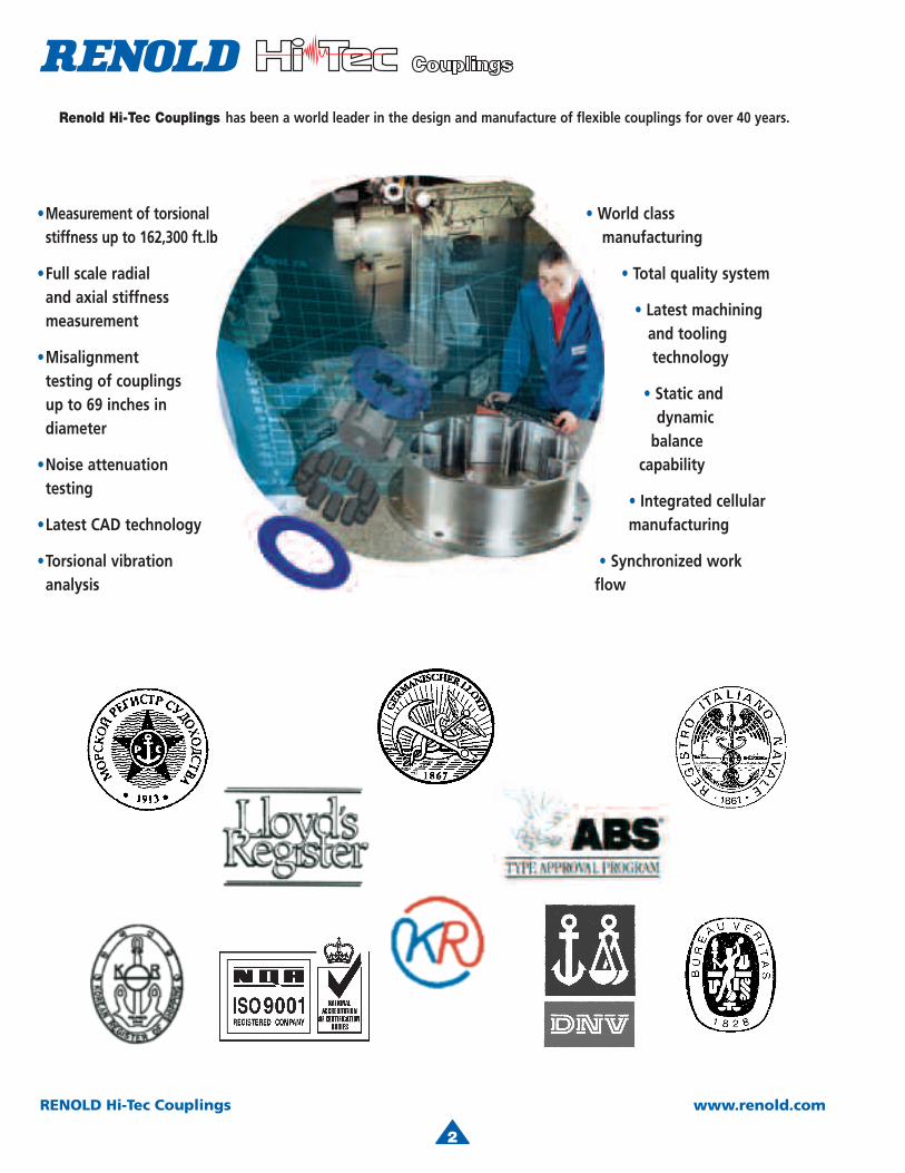
Renold Hi-Tec Couplings has been a world leader in the design and manufacture of flexible couplings for over 40 years.
•Measurement of torsionalstiffness up to 162,300 ft.lb
•Full scale radial and axial stiffness measurement
•Misalignment testing of couplingsup to 69 inches indiameter
•Noise attenuation testing
•Latest CAD technology
•Torsional vibration analysis
• World class manufacturing
• Total quality system
• Latest machining and tooling technology
• Static and dynamic balance capability
• Integrated cellular manufacturing
• Synchronized work flow
4
3
RENOLD Hi-Tec Couplings www.renold.com
DCB CouplingFeatures & benefits 5Typical applications 7Series 6 8Series 8 10Technical data 13Design variations 20
HTB Coupling 21Features & benefits 22Typical applications 23Flywheel mounted 24Technical data 25Design variations 28
RB Coupling 29Features & benefits 30Typical applications 31Shaft to shaft 32Flywheel mounted 34Technical data 38Design variations 41
PM Coupling 42Features & benefits 43Typical applications 44Shaft to shaft 45Technical data 47Technical data standard blocks 48
Design variations 50Selection Procedure 51Selection Checklist 52Selection Procedure 53Driven equipment service factors 54
Selection examples 55 Transient analysis 56 Rubber information 57 Damping characteristics 58NEW DCB GS Coupling 59
Page No
Contents
4
RENOLD Hi-Tec Couplings www.renold.com
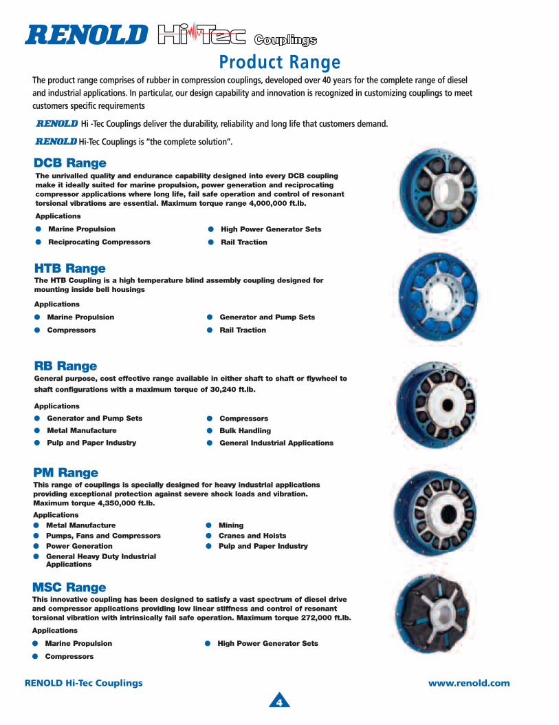
RB RangeGeneral purpose, cost effective range available in either shaft to shaft or flywheel to
shaft configurations with a maximum torque of 30,240 ft.lb.
Applications
● Generator and Pump Sets
● Metal Manufacture
● Pulp and Paper Industry
● Compressors
● Bulk Handling
● General Industrial Applications
DCB RangeThe unrivalled quality and endurance capability designed into every DCB coupling make it ideally suited for marine propulsion, power generation and reciprocatingcompressor applications where long life, fail safe operation and control of resonanttorsional vibrations are essential. Maximum torque range 4,000,000 ft.lb.
Applications
● Marine Propulsion
● Reciprocating Compressors
● High Power Generator Sets
● Rail Traction
MSC RangeThis innovative coupling has been designed to satisfy a vast spectrum of diesel driveand compressor applications providing low linear stiffness and control of resonanttorsional vibration with intrinsically fail safe operation. Maximum torque 272,000 ft.lb.
Applications
● Marine Propulsion
● Compressors
● High Power Generator Sets
PM RangeThis range of couplings is specially designed for heavy industrial applicationsproviding exceptional protection against severe shock loads and vibration.Maximum torque 4,350,000 ft.lb.
Applications● Metal Manufacture● Pumps, Fans and Compressors● Power Generation● General Heavy Duty Industrial
Applications
● Mining● Cranes and Hoists● Pulp and Paper Industry
HTB RangeThe HTB Coupling is a high temperature blind assembly coupling designed for mounting inside bell housings
Applications
● Marine Propulsion
● Compressors
● Generator and Pump Sets
● Rail Traction
The product range comprises of rubber in compression couplings, developed over 40 years for the complete range of dieseland industrial applications. In particular, our design capability and innovation is recognized in customizing couplings to meet customers specific requirements
R ENOLD Hi -Tec Couplings deliver the durability, reliability and long life that customers demand.
RENO LD Hi-Tec Couplings is “the complete solution”.
Product Range

4
5
RENOLD Hi-Tec Couplings www.renold.comRENOLD Hi-Tec Couplings. Tel: + 44 (0) 1422 255000 Fax: + 44 (0) 1422 255100 E-Mail: [email protected]
6
RENOLD Hi-Tec Couplings www.renold.com
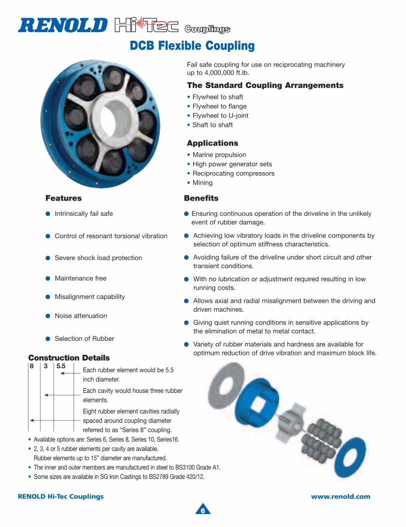
Fail safe coupling for use on reciprocating machinery up to 4,000,000 ft.lb.
The Standard Coupling Arrangements• Flywheel to shaft• Flywheel to flange• Flywheel to U-joint• Shaft to shaft
Applications• Marine propulsion• High power generator sets• Reciprocating compressors• Mining
Features
● Intrinsically fail safe
● Control of resonant torsional vibration
● Severe shock load protection
● Maintenance free
● Misalignment capability
● Noise attenuation
● Selection of Rubber
Each rubber element would be 5.5inch diameter.
Each cavity would house three rubber elements.
Eight rubber element cavities radiallyspaced around coupling diameter referred to as “Series 8” coupling.
8 3 5.5
Benefits
● Ensuring continuous operation of the driveline in the unlikely event of rubber damage.
● Achieving low vibratory loads in the driveline components by selection of optimum stiffness characteristics.
● Avoiding failure of the driveline under short circuit and other transient conditions.
● With no lubrication or adjustment required resulting in low running costs.
● Allows axial and radial misalignment between the driving and driven machines.
● Giving quiet running conditions in sensitive applications by the elimination of metal to metal contact.
● Variety of rubber materials and hardness are available for optimum reduction of drive vibration and maximum block life.
DCB Flexible Coupling
6
Construction Details
• Available options are: Series 6, Series 8, Series 10, Series16.• 2, 3, 4 or 5 rubber elements per cavity are available. Rubber elements up to 15” diameter are manufactured.• The inner and outer members are manufactured in steel to BS3100 Grade A1.• Some sizes are available in SG Iron Castings to BS2789 Grade 420/12.
4
7
RENOLD Hi-Tec Couplings www.renold.com
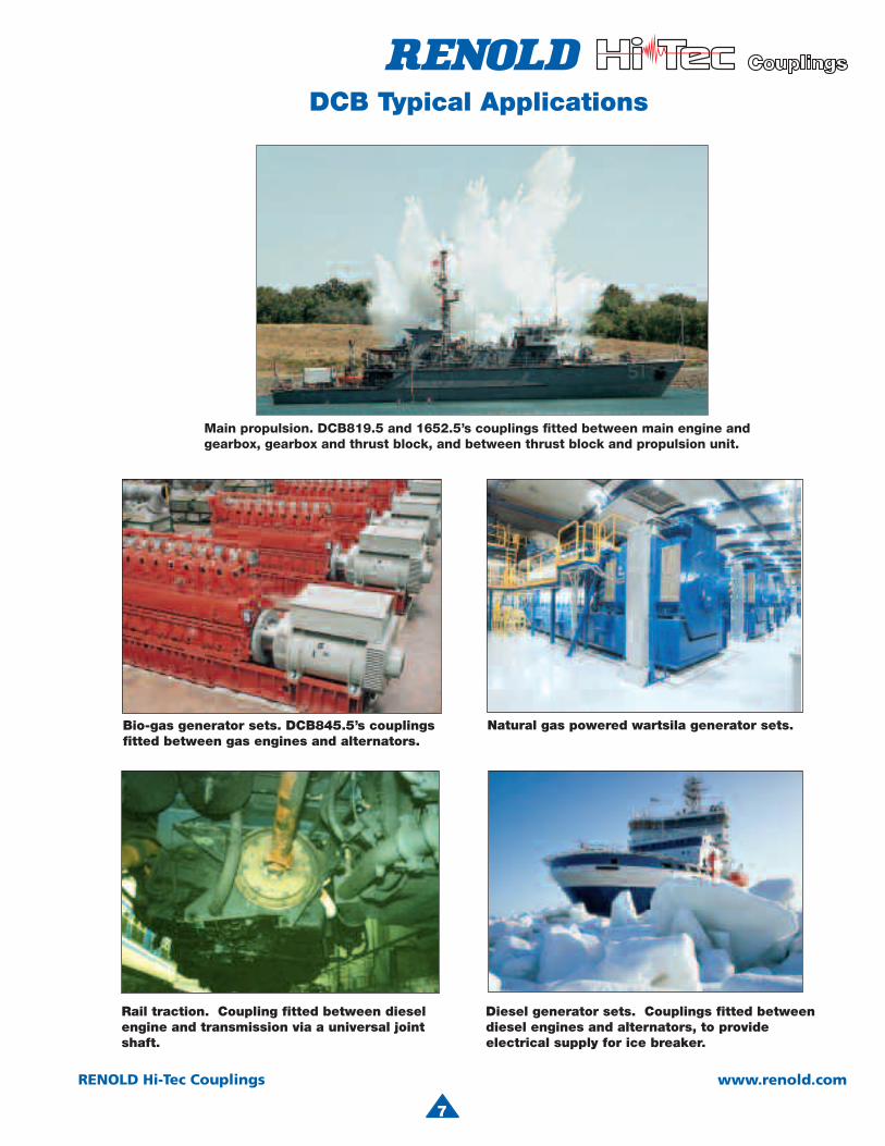
DCB Typical Applications
Diesel generator sets. Couplings fitted betweendiesel engines and alternators, to provideelectrical supply for ice breaker.
Rail traction. Coupling fitted between dieselengine and transmission via a universal joint shaft.
7
Main propulsion. DCB819.5 and 1652.5’s couplings fitted between main engine andgearbox, gearbox and thrust block, and between thrust black and propulsion unit.
Bio-gas generator sets. DCB845.5’s couplingsfitted between gas engines and alternators.
Natural gas powered wartsila generator sets.

8
RENOLD Hi-Tec Couplings www.renold.com
A 11.02 11.02 14.57 14.57 17.91 22.24 26.57 31.89 31.89 B 5.55 8.07 7.64 11.10 9.72 12.05 14.29 17.48 25.51 C 0.12 0.12 0.16 0.16 0.20 0.24 0.28 0.31 0.31 D 2.72 3.98 3.74 5.47 4.76 5.91 7.01 8.58 12.60 D1 2.72 3.98 3.74 5.47 4.76 5.91 7.01 8.58 12.60 E 3.23 3.23 4.41 4.41 5.59 7.09 8.46 10.24 10.24 F 10.04 10.04 13.58 13.58 16.93 20.87 24.80 30.12 30.12 G 8.86 8.86 12.40 12.40 15.75 19.29 22.83 28.15 28.15 DIMENSIONS J 0.55 0.55 0.55 0.55 0.55 0.71 0.98 0.98 0.98 (inch) K 0.33 0.33 0.39 0.39 0.45 0.63 0.79 0.91 0.91 L 3.19 4.45 4.29 6.02 5.43 6.77 8.07 9.80 13.82 Q (QTY) 6 6 6 6 6 6 6 6 6
R M10 M10 M10 M10 M10 M16 M20 M20 M20S (QTY) 8 12 12 18 16 8 8 12 18
T M10 M10 M10 M10 M10 M16 M20 M20 M20 U 0.41 0.41 0.41 0.41 0.41 0.67 0.83 0.83 0.83 MAX. X 1.97 1.97 2.76 2.76 3.54 4.33 5.12 6.50 6.50 MAX. Y 1.97 1.97 2.76 2.76 3.54 4.33 5.12 6.50 6.50 MAXIMUM SPEED (rpm)(1) 4150 4150 3150 3150 2570 2080 1730 1440 1440 W1 7.3 11.0 19.6 29.5 40.6 74.1 127.2 228.8 343.3 WEIGHT (3) W2 22.5 32.0 52.7 74.7 96.8 187.4 322.1 575.8 817.0(lb) W3 21.8 24.7 33.3 42.8 55.3 113.8 216.3 320.3 367.5
W4 8.8 8.8 16.8 16.8 30.2 62.4 111.1 183.4 183.4J1 30 45 164 246 569 1550 3752 10347 15520
INERTIA (3) J2 364 518 1557 2209 4486 13159 31946 84232 119497 (lb.in2) J3 263 287 556 823 1674 5159 14522 30139 31095
J4 143 143 481 481 1329 4237 10798 25662 25662ALLOWABLE MISALIGNMENT (2) RADIAL (inch) 0.06 0.06 0.08 0.08 0.10 0.12 0.14 0.16 0.16AXIAL (inch) 0.06 0.06 0.08 0.08 0.10 0.12 0.14 0.16 0.16 CONICAL (degree) 0.7 0.7 0.7 0.7 0.7 0.7 0.7 0.7 0.7
(1) For operation above 80% of the declared maximum coupling speed, it is recommended that the coupling is dynamically balanced.
(2) Installations should be initially aligned as accurately as possible. In order to allow for deterioration in alignment over time, it is recommended that initial alignment should not exceed 25% of the above noted data. The forces on the driving and driven machinery should be calculated to ensure that these do not exceed the manufacturers allowables.
(3) Weights and inertias are based on the maximum bore size.
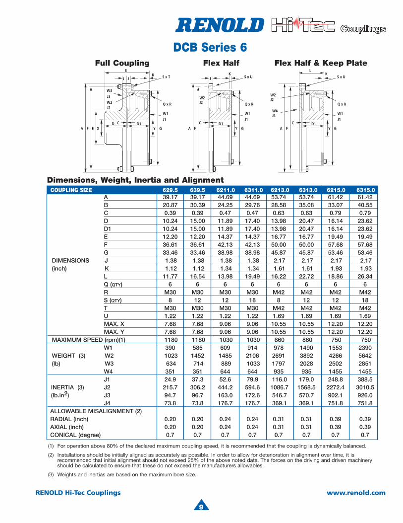
Full Coupling Flex Half Flex Half & Keep Plate
Dimensions, Weight, Inertia and Alignment
DCB Series 6
COUPLING SIZE 622.5 632.5 623.5 633.5 624.5 625.5 626.5 628.0 638.0
4
9
RENOLD Hi-Tec Couplings www.renold.com
A 39.17 39.17 44.69 44.69 53.74 53.74 61.42 61.42 B 20.87 30.39 24.25 29.76 28.58 35.08 33.07 40.55 C 0.39 0.39 0.47 0.47 0.63 0.63 0.79 0.79 D 10.24 15.00 11.89 17.40 13.98 20.47 16.14 23.62 D1 10.24 15.00 11.89 17.40 13.98 20.47 16.14 23.62 E 12.20 12.20 14.37 14.37 16.77 16.77 19.49 19.49 F 36.61 36.61 42.13 42.13 50.00 50.00 57.68 57.68 G 33.46 33.46 38.98 38.98 45.87 45.87 53.46 53.46 DIMENSIONS J 1.38 1.38 1.38 1.38 2.17 2.17 2.17 2.17 (inch) K 1.12 1.12 1.34 1.34 1.61 1.61 1.93 1.93 L 11.77 16.54 13.98 19.49 16.22 22.72 18.86 26.34 Q (QTY) 6 6 6 6 6 6 6 6
R M30 M30 M30 M30 M42 M42 M42 M42 S (QTY) 8 12 12 18 8 12 12 18 T M30 M30 M30 M30 M42 M42 M42 M42
U 1.22 1.22 1.22 1.22 1.69 1.69 1.69 1.69 MAX. X 7.68 7.68 9.06 9.06 10.55 10.55 12.20 12.20 MAX. Y 7.68 7.68 9.06 9.06 10.55 10.55 12.20 12.20 MAXIMUM SPEED (rpm)(1) 1180 1180 1030 1030 860 860 750 750 W1 390 585 609 914 978 1490 1553 2390 WEIGHT (3) W2 1023 1452 1485 2106 2691 3892 4266 5642 (lb) W3 634 714 889 1033 1797 2028 2502 2851
W4 351 351 644 644 935 935 1455 1455J1 24.9 37.3 52.6 79.9 116.0 179.0 248.8 388.5
INERTIA (3) J2 215.7 306.2 444.2 594.6 1086.7 1568.5 2272.4 3010.5(lb.in2) J3 94.7 96.7 163.0 172.6 546.7 570.7 902.1 926.0 J4 73.8 73.8 176.7 176.7 369.1 369.1 751.8 751.8ALLOWABLE MISALIGNMENT (2)RADIAL (inch) 0.20 0.20 0.24 0.24 0.31 0.31 0.39 0.39AXIAL (inch) 0.20 0.20 0.24 0.24 0.31 0.31 0.39 0.39CONICAL (degree) 0.7 0.7 0.7 0.7 0.7 0.7 0.7 0.7
(1) For operation above 80% of the declared maximum coupling speed, it is recommended that the coupling is dynamically balanced.
(2) Installations should be initially aligned as accurately as possible. In order to allow for deterioration in alignment over time, it is recommended that initial alignment should not exceed 25% of the above noted data. The forces on the driving and driven machinery should be calculated to ensure that these do not exceed the manufacturers allowables.
(3) Weights and inertias are based on the maximum bore size.
Full Coupling Flex Half Flex Half & Keep Plate
Dimensions, Weight, Inertia and Alignment
DCB Series 6
COUPLING SIZE 629.5 639.5 6211.0 6311.0 6213.0 6313.0 6215.0 6315.0
9

10
RENOLD Hi-Tec Couplings www.renold.com
A 12.80 16.73 18.37 16.73 18.37 21.65 22.50 21.65 22.50 21.65 22.50 B 5.47 7.64 - 11.10 - 9.80 - 14.29 - 16.54 -
C 0.12 0.16 0.16 0.16 0.16 0.20 0.20 0.20 0.20 0.20 0.20 D 2.68 3.74 - 5.47 - 4.80 - 7.05 - 7.05 - D1 2.68 3.74 3.74 5.47 5.47 4.80 4.80 7.05 7.05 9.29 9.29 E 5.12 6.89 - 6.89 - 8.86 - 8.86 - 8.86 - F 11.81 15.75 17.24 15.75 17.24 20.28 21.38 20.28 21.38 20.28 21.38 G 10.63 14.57 14.57 14.57 14.57 18.70 18.70 18.70 18.70 18.70 18.70 DIMENSIONS J 0.55 0.55 0.55 0.55 0.55 0.71 0.71 0.71 0.71 0.71 0.71 (inch) K 0.31 0.39 0.39 0.39 0.39 0.49 0.49 0.49 0.49 0.49 0.49 L 3.11 4.25 4.25 6.02 6.02 5.51 5.51 7.76 7.76 10.00 10.00 Q (QTY) 8 8 8 8 8 8 8 8 8 8 8
R M10 M10 M10 M10 M10 M16 M16 M16 M16 M16 M16 S (QTY) 8 12 8 24 8 8 6 16 6 16 6
T M10 M10 - M10 - M16 - M16 - M16 -U 0.41 0.41 0.53 0.41 0.53 0.67 0.67 0.67 0.67 0.67 0.67
MAX. X 3.15 4.25 - 4.25 - 5.51 - 5.51 0.00 5.51 - MAX. Y 3.15 4.25 4.25 4.25 4.25 5.51 5.51 5.51 5.51 5.51 5.51 MAXIMUM SPEED (rpm)(1) 3600 2760 2760 2760 2760 2130 2130 2130 2130 2130 2130 W1 13.5 35.2 35.2 52.5 52.5 76.3 76.3 114.0 114.0 151.9 151.9 WEIGHT (3) W2 28.0 66.8 67.2 85.1 89.9 123.9 129.6 170.4 176.1 208.3 214.1(lb) W3 26.9 53.4 - 64.8 - 113.3 - 137.6 - 137.6 -
W4 9.7 18.5 22.9 18.5 22.9 44.5 48.7 44.5 48.7 44.5 48.7J1 95 464 464 697 697 1681 1681 2525 2525 3379 3379
INERTIA (3) J2 666 3277 3632 4127 4479 9544 10063 12089 12609 14666 15185
(lb.in2) J3 420 1370 - 1664 - 4920 - 5228 - 5228 -J4 228 748 1100 748 1100 3034 3553 3034 3553 3034 3553
ALLOWABLE MISALIGNMENT (2)RADIAL (inch) 0.06 0.08 0.08 0.08 0.08 0.10 0.10 0.10 0.10 0.10 0.10AXIAL (inch) 0.06 0.08 0.08 0.08 0.08 0.10 0.10 0.10 0.10 0.10 0.10CONICAL (degree) 0.6 0.6 0.6 0.6 0.6 0.6 0.6 0.6 0.6 0.6 0.6
(1) For operation above 80% of the declared maximum coupling speed, it is recommended that the coupling is dynamically balanced.
(2) Installations should be initially aligned as accurately as possible. In order to allow for deterioration in alignment over time, it is recommended that initial alignment should not exceed 25% of the above noted data. The forces on the driving and driven machinery should be calculated to ensure that these do not exceed the manufacturers allowables.
(3) Weights and inertias are based on the maximum bore size.
Full Coupling Flex Half Flex Half & Keep Plate
Dimensions, Weight, Inertia and AlignmentCOUPLING SIZE 822.5 823.5 823.5 833.5 833.5 824.5 824.5 834.5 834.5 844.5 844.5
SAE14 SAE14 SAE18 SAE18 SAE18
DCB Series 8
10
4
11
RENOLD Hi-Tec Couplings www.renold.com
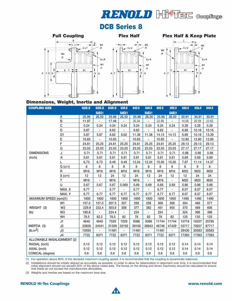
A 25.98 26.50 25.98 26.50 25.98 26.50 25.98 26.50 30.91 30.91 30.91B 11.97 - 17.48 - 20.24 - 22.99 - 14.06 20.59 23.82C 0.24 0.24 0.24 0.24 0.24 0.24 0.24 0.24 0.28 0.28 0.28
D 5.87 - 8.62 - 8.62 - 8.62 - 6.89 10.16 10.16D1 5.87 5.87 8.62 8.62 11.38 11.38 14.13 14.13 6.89 10.16 13.39E 10.83 - 10.83 - 10.83 - 10.83 - 12.80 12.80 12.80
F 24.61 25.25 24.61 25.25 24.61 25.25 24.61 25.25 29.13 29.13 29.13 G 23.03 23.03 23.03 23.03 23.03 23.03 23.03 23.03 27.17 27.17 27.17 DIMENSIONS J 0.71 0.71 0.71 0.71 0.71 0.71 0.71 0.71 0.98 0.98 0.98 (inch) K 0.61 0.61 0.61 0.61 0.61 0.61 0.61 0.61 0.69 0.69 0.69 L 6.73 6.73 9.49 9.49 12.24 12.24 15.00 15.00 7.87 11.14 14.37
Q (QTY) 8 8 8 8 8 8 8 8 8 8 8R M16 M16 M16 M16 M16 M16 M16 M16 M20 M20 M20
S (QTY) 12 12 24 12 24 12 24 12 12 24 24T M16 - M16 - M16 - M16 - M20 M20 M20
U 0.67 0.67 0.67 0.069 0.69 0.69 0.69 0.69 0.86 0.86 0.86 MAX. X 6.77 - 6.77 - 6.77 - 6.77 - 8.07 8.07 8.07 MAX. Y 6.77 6.77 6.77 6.77 6.77 6.77 6.77 6.77 8.07 8.07 8.07 MAXIMUM SPEED (rpm)(1) 1800 1800 1800 1800 1800 1800 1800 1800 1490 1490 1490 W1 157.0 157.0 207.5 207 258 258 308 308 354 466 577 WEIGHT (3) W2 229.9 232.4 303.6 308 377 382 451 455 370 489 606(lb) W3 180.8 - 224.4 - 224 - 224 - 324 396 396
W4 78.5 82.2 78.5 82 78 82 78 82 125 125 125J1 4640 4640 7029 7029 9386 9386 11744 11744 10716 16207 25785
INERTIA (3) J2 23858 24541 31509 32192 39160 39843 46746 47429 53717 70837 87717(lb.in2) J3 10593 - 11481 - 11481 - 11481 - 28430 30583 30583 J4 7722 8371 7722 8371 7722 8371 7722 8371 17393 17393 17393ALLOWABLE MISALIGNMENT (2)RADIAL (inch) 0.12 0.12 0.12 0.12 0.12 0.12 0.12 0.12 0.14 0.14 0.14AXIAL (inch) 0.12 0.12 0.12 0.12 0.12 0.12 0.12 0.12 0.14 0.14 0.14CONICAL (degree) 0.6 0.6 0.6 0.6 0.6 0.6 0.6 0.6 0.6 0.6 0.6
(1) For operation above 80% of the declared maximum coupling speed, it is recommended that the coupling is dynamically balanced.(2) Installations should be initially aligned as accurately as possible. In order to allow for deterioration in alignment over time, it is recommended that
initial alignment should not exceed 25% of the above noted data. The forces on the driving and driven machinery should be calculated to ensure that these do not exceed the manufacturers allowables.
(3) Weights and inertias are based on the maximum bore size.
Full Coupling Flex Half Flex Half & Keep Plate
Dimensions, Weight, Inertia and Alignment
DCB Series 8
COUPLING SIZE 825.5 825.5 835.5 835.5 845.5 845.5 855.5 855.5 826.5 836.5 846.5 SAE21 SAE21 SAE21 SAE21
11

12
RENOLD Hi-Tec Couplings www.renold.com
(1) For operation above 80% of the declared maximum coupling speed, it is recommended that the coupling is dynamically balanced.
(2) Installations should be initially aligned as accurately as possible. In order to allow for deterioration in alignment over time, it is recommended that initial alignment should not exceed 25% of the above noted data. The forces on the driving and driven machinery should be calculated to ensure that these do not exceed the manufacturers allowables.
(3) Weights and inertias are based on the maximum bore size.
Full Coupling Flex Half Flex Half & Keep Plate
Dimensions, Weight, Inertia and AlignmentCOUPLING SIZE 827.5 837.5 847.5 857.5 828.0 838.0 848.0 858.0 829.5 839.5 849.5 859.5 8211.0
DCB Series 8
A 35.04 35.04 35.04 35.04 37.01 37.01 37.01 37.01 45.67 45.67 45.67 45.67 52.36 B 16.30 23.86 27.60 31.34 17.32 25.35 29.37 33.39 20.79 30.31 35.08 39.84 24.09 C 0.31 0.31 0.31 0.31 0.31 0.31 0.31 0.31 0.39 0.39 0.39 0.39 0.47 D 7.99 11.77 11.77 11.77 8.50 12.52 12.52 12.52 10.20 14.96 14.96 14.96 11.81 D1 7.99 11.77 15.51 19.25 8.50 12.52 16.54 20.51 10.20 14.96 19.72 24.49 11.81 E 14.96 14.96 14.96 14.96 15.55 15.55 15.55 15.55 18.70 18.70 18.70 18.70 22.05 F 33.27 33.27 33.27 33.27 35.24 35.24 35.24 35.24 43.11 43.11 43.11 43.11 49.80 G 31.30 31.30 31.30 31.30 33.27 33.27 33.27 33.27 39.96 39.96 39.96 39.96 46.65 DIMENSIONS J 0.98 0.98 0.98 0.98 0.98 0.98 0.98 0.98 1.38 1.38 1.38 1.38 1.38 (inch) K 0.83 0.83 0.83 0.83 0.83 0.83 0.83 0.83 1.10 1.10 1.10 1.10 1.30 L 9.09 12.87 16.61 20.35 9.65 13.66 17.68 21.65 11.69 16.46 21.22 26.22 13.58 Q (QTY) 8 8 8 8 8 8 8 8 8 8 8 8 8
R M20 M20 M20 M20 M20 M20 M20 M20 M30 M30 M30 M30 M30 S (QTY) 16 32 32 32 16 32 32 32 12 24 24 24 16
T M20 M20 M20 M20 M20 M20 M20 M20 M30 M30 M30 M30 M30 U 0.86 0.86 0.86 0.86 0.86 0.86 0.83 0.83 1.22 1.22 1.22 1.22 1.22
MAX. X 9.45 9.45 9.45 9.45 9.84 9.84 9.84 9.84 11.81 11.81 11.81 11.81 13.78 MAX. Y 9.45 9.45 9.45 9.45 9.84 9.84 9.84 9.84 11.81 11.81 11.81 11.81 13.78 MAXIMUM SPEED (rpm)(1) 1315 1315 1315 1315 1240 1240 1240 1240 1010 1010 1010 1010 880 W1 345 513 680 848 423 633 843 1,053 735 1,099 1,463 18.47 1,151WEIGHT (3) W2 557 740 922 1103 649 866 1,084 1,299 1,224 1,609 1,993 2,377 1,909(lb) W3 458 571 571 571 520 520 650 650 1,008 1,230 1,230 1,230 1,466
W4 177 177 177 177 207 207 207 207 423 423 423 423 648J1 21.4 32.0 42.6 53.2 29.5 44.4 59.4 74.4 73.4 110.6 147.8 185.0 156.0
INERTIA (3) J2 105.1 140.3 174.8 209.6 137.9 185.0 231.8 278.2 382.7 502.3 621.9 741.5 799.6(lb.in2) J3 49.5 53.6 53.6 53.6 61.5 66.6 66.6 666.3 191.4 204.3 204.3 204.3 345.1
J4 31.9 31.9 31.9 31.9 41.7 41.7 41.7 41.7 129.2 129.2 129.2 129.2 261.4ALLOWABLE MISALIGNMENT (2) RADIAL (inch) 0.16 0.16 0.16 0.16 0.16 0.16 0.16 0.16 0.20 0.20 0.20 0.20 0.24AXIAL (inch) 0.16 0.16 0.16 0.16 0.16 0.16 0.16 0.16 0.20 0.20 0.20 0.20 0.24CONICAL (degree) 0.6 0.6 0.6 0.6 0.6 0.6 0.6 0.6 0.6 0.6 0.6 0.6 0.6
12
4
13
RENOLD Hi-Tec Couplings www.renold.com
2.1 Axial StiffnessWhen subject to axial misalignment, the coupling will have an axial resistance which gradually reduces due to the effect of vibratory torque.
The axial stiffness of the coupling is torque dependent. The variation is as shown in the Technical Data
2.2 Radial StiffnessThe radial stiffness of the coupling is torque dependent, and is as shown in the Technical Data
2.3 Torsional StiffnessThe torsional stiffness of the coupling is dependent upon applied torque and temperature as shown in the Technical Data
2.4 Prediction of the System Torsional Vibration Characteristics.An adequate prediction of the system’s torsional vibration characteristics, can be made by the following method.
2.4.1 Use the torsional stiffness, as published in the catalog, which is based upon data measured at 86˚F ambient temperature.
2.4.2 Repeat the calculation made in 2.4.1 but using the maximum temperature correction factor St212, and dynamic magnifier correction factor, M212, for the selected rubber. Use tables to adjust values for both torsional stiffness and dynamic magnifier. ie, CT212 = CTdynX St212
2.4.3 Review calculations 2.4.1 and 2.4.2 and if the speed range is clear of criticals which do not exceed the allowable heat dissipation value as published in the catalog then the coupling is considered suitable for the application, with respect to the torsional vibration characteristics. If there is a critical in the speed range, then the actual temperature of the coupling should be calculated at this speed.
DCB Technical Data
1.1 Torque Capacity - DieselEngine Drives
The full torque capacity of the coupling for transient vibration while passing through major criticals on run up is published as the Maximum Torque TKMAX
(TKMAX = 3 x TKN.)
There is additional torque capacity built within the coupling for transient shock.
The published “Vibratory Torque, TKW ”, relates to the amplitude of the permissible continous torque fluctuation. The vibratory torque values shown in the Technical Data are at a frequency of 10Hz. The measure of acceptability of the coupling for vibrating drives is published as “Allowable Dissipated Heat at Ambient Temperature 86°F”.
1.2 Transient TorquesPrediction of transient torques in marine drives can be complex. Normal installations are well provided for by selecting couplings based on the “Nominal Torque TKN .” Transients, such as start up and clutch maneuver, are usually within the “Maximum Torque, TKMAX” for the coupling.
Care needs to be taken in the design of couplings with shaft brakes, to ensure coupling torques are not increased by severe deceleration.
Sudden torque applications of propulsion devices, such as thrusters or waterjets, needto be considered when designing the coupling connection.
2.0 Stiffness PropertiesThe Renold Hi-Tec Coupling remains fully flexible under all torque conditions. The DCB series is a non-bonded type operating with the Rubber-in-Compression principle.
13
14
RENOLD Hi-Tec Couplings www.renold.com
DCB Technical Data
SM 60 is considered “standard”
RubberGrade
NM 45SM 50SM 60SM 70SM 80
DynamicMagnifier
(M86)
1510864
RelativeDamping
ψ86
0.420.630.781.051.57
SM 60 is considered “standard”
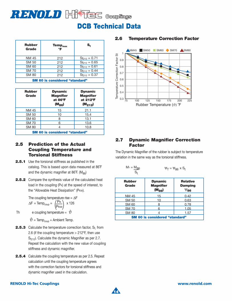
2.6 Temperature Correction Factor
2.5 Prediction of the ActualCoupling Temperature and
Torsional Stiffness2.5.1 Use the torsional stiffness as published in the
catalog. This is based upon data measured at 86˚F and the dynamic magnifier at 86˚F. (M86)
2.5.2 Compare the synthesis value of the calculated heat load in the coupling (PK) at the speed of interest, to the “Allowable Heat Dissipation” (PKW).
The coupling temperature rise = ∆F∆F = Tempcoup = x 126
Th e coupling temperature = ϑϑ = Tempcoup + Ambient Temp.
2.5.3 Calculate the temperature correction factor, St, from 2.6 (if the coupling temperature > 212ºF, then use St212). Calculate the dynamic Magnifier as per 2.7.Repeat the calculation with the new value of couplingstiffness and dynamic magnifier.
2.5.4 Calculate the coupling temperature as per 2.5. Repeat calculation until the coupling temperature agreeswith the correction factors for torsional stiffness and dynamic magnifier used in the calculation.
PK
PKW( )
MT = M86St
ψT = ψ86 x St
RubberGrade
NM 45SM 50SM 60SM 70SM 80
Tempmax°F
212212212212212
St
St212 = 0.71St212 = 0.65St212 = 0.61St212 = 0.44St212 = 0.37
SM 60 is considered “standard”
RubberGrade
NM 45SM 50SM 60SM 70SM 80
DynamicMagnifierat 86ºF(M86)
1510864
DynamicMagnifierat 212ºF(M212)
21.115.413.113.610.8
2.7 Dynamic Magnifier Correction FactorThe Dynamic Magnifier of the rubber is subject to temperature variation in the same way as the torsional stiffness.
14
Rubber Temperature (ϑ) ˚F
4
15
RENOLD Hi-Tec Couplings www.renold.com
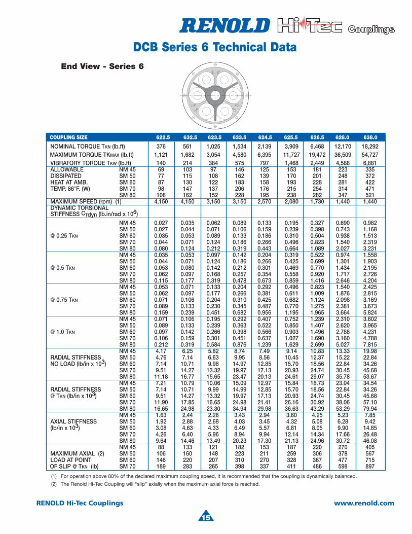
NOMINAL TORQUE TKN (lb.ft) 376 561 1,025 1,534 2,139 3,909 6,468 12,170 18,292 MAXIMUM TORQUE TKMAX (lb.ft) 1,121 1,682 3,054 4,580 6,395 11,727 19,472 36,509 54,727 VIBRATORY TORQUE TKW (lb.ft) 140 214 384 575 797 1,468 2,449 4,588 6,881 ALLOWABLE NM 45 69 103 97 146 125 153 181 223 335 DISSIPATED SM 50 77 115 108 162 139 170 201 248 372
HEAT AT AMB. SM 60 87 130 122 183 158 193 228 281 422TEMP. 86°F. (W) SM 70 98 147 137 206 176 215 254 314 471
SM 80 108 162 152 228 195 238 282 347 521MAXIMUM SPEED (rpm) (1) 4,150 4,150 3,150 3,150 2,570 2,080 1,730 1,440 1,440
DYNAMIC TORSIONALSTIFFNESS CTdyn (lb.in/rad x 106)
NM 45 0.027 0.035 0.062 0.089 0.133 0.195 0.327 0.690 0.982SM 50 0.027 0.044 0.071 0.106 0.159 0.239 0.398 0.743 1.168
@ 0.25 TKN SM 60 0.035 0.053 0.089 0.133 0.186 0.310 0.504 0.938 1.513SM 70 0.044 0.071 0.124 0.186 0.266 0.496 0.823 1.540 2.319SM 80 0.080 0.124 0.212 0.319 0.443 0.664 1.089 2.027 3.231NM 45 0.035 0.053 0.097 0.142 0.204 0.319 0.522 0.974 1.558SM 50 0.044 0.071 0.124 0.186 0.266 0.425 0.699 1.301 1.903
@ 0.5 TKN SM 60 0.053 0.080 0.142 0.212 0.301 0.469 0.770 1.434 2.195 SM 70 0.062 0.097 0.168 0.257 0.354 0.558 0.920 1.717 2.726 SM 80 0.115 0.177 0.319 0.478 0.673 0.859 1.416 2.646 4.204 NM 45 0.053 0.071 0.133 0.204 0.292 0.496 0.823 1.540 2.425 SM 50 0.062 0.097 0.177 0.266 0.381 0.611 1.009 1.876 2.815 @ 0.75 TKN SM 60 0.071 0.106 0.204 0.310 0.425 0.682 1.124 2.098 3.169
SM 70 0.089 0.133 0.230 0.345 0.487 0.770 1.275 2.381 3.673SM 80 0.159 0.239 0.451 0.682 0.956 1.195 1.965 3.664 5.824NM 45 0.071 0.106 0.195 0.292 0.407 0.752 1.239 2.310 3.602SM 50 0.089 0.133 0.239 0.363 0.522 0.850 1.407 2.620 3.965
@ 1.0 TKN SM 60 0.097 0.142 0.266 0.398 0.566 0.903 1.496 2.788 4.231 SM 70 0.106 0.159 0.301 0.451 0.637 1.027 1.690 3.160 4.788 SM 80 0.212 0.319 0.584 0.876 1.239 1.629 2.699 5.027 7.815 NM 45 4.17 6.25 5.82 8.74 7.49 9.14 10.83 13.33 19.98 RADIAL STIFFNESS SM 50 4.76 7.14 6.63 9.95 8.56 10.45 12.37 15.22 22.84 NO LOAD (lb/in x 103) SM 60 7.14 10.71 9.98 14.97 12.85 15.70 18.56 22.84 34.26
SM 70 9.51 14.27 13.32 19.97 17.13 20.93 24.74 30.45 45.68SM 80 11.18 16.77 15.65 23.47 20.13 24.61 29.07 35.78 53.67NM 45 7.21 10.79 10.06 15.09 12.97 15.84 18.73 23.04 34.54
RADIAL STIFFNESS SM 50 7.14 10.71 9.99 14.99 12.85 15.70 18.56 22.84 34.26@ TKN (lb/in x 103) SM 60 9.51 14.27 13.32 19.97 17.13 20.93 24.74 30.45 45.68
SM 70 11.90 17.85 16.65 24.98 21.41 26.16 30.92 38.06 57.10SM 80 16.65 24.98 23.30 34.94 29.98 36.63 43.29 53.29 79.94NM 45 1.63 2.44 2.28 3.43 2.94 3.60 4.25 5.23 7.85
AXIAL STIFFNESS SM 50 1.92 2.88 2.68 4.03 3.45 4.32 5.08 6.28 9.42(lb/in x 103) SM 60 3.08 4.63 4.33 6.49 5.57 6.81 8.05 9.90 14.85
SM 70 4.26 6.40 5.96 8.94 9.94 12.14 14.34 17.66 26.48SM 80 9.64 14.46 13.49 20.23 17.30 21.13 24.96 30.72 46.08NM 45 88 133 121 182 153 187 220 270 405
MAXIMUM AXIAL (2) SM 50 106 160 148 223 211 259 306 378 567LOAD AT POINT SM 60 146 220 207 310 270 328 387 477 715OF SLIP @ TKN (lb) SM 70 189 283 265 398 337 411 486 598 897
(1) For operation above 80% of the declared maximum coupling speed, it is recommended that the coupling is dynamically balanced.
(2) The Renold Hi-Tec Coupling will “slip” axially when the maximum axial force is reached.
End View - Series 6
DCB Series 6 Technical Data
COUPLING SIZE 622.5 632.5 623.5 633.5 624.5 625.5 626.5 628.0 638.0
15

16
RENOLD Hi-Tec Couplings www.renold.com
DCB Series 6 Technical Data
(1) For operation above 80% of the declared maximum coupling speed, it is recommended that the coupling is dynamically balanced.
(2) The Renold Hi-Tec Coupling will “slip” axially when the maximum axial force is reached.
NOMINAL TORQUE TKN (lb.ft) 20,283 30,461 31,789 47,720 52,662 78,919 81,132 122,435 MAXIMUM TORQUE TKMAX (lb.ft) 60,923 91,458 95,883 143,087 157,838 236,757 244,133 366,568 VIBRATORY TORQUE TKW (lb.ft) 7,671 11,506 11,948 17,923 19,693 29,502 30,461 45,729 ALLOWABLE NM 45 265 398 306 459 362 543 418 627 DISSIPATED SM 50 294 441 340 510 402 603 464 696 HEAT AT AMB. SM 60 333 500 386 579 456 684 526 789 TEMP. 86°F. (W) SM 70 372 558 431 646 510 765 588 882 SM 80 412 618 477 716 563 845 650 975 MAXIMUM SPEED (rpm) (1) 1,180 1,180 1,030 1,030 860 860 750 750 DYNAMIC TORSIONAL
STIFFNESS CTdyn (lb.in/rad x 106)NM 45 1.03 1.65 1.58 2.55 2.62 4.20 4.02 6.46SM 50 1.25 1.96 1.94 3.04 3.20 5.02 4.91 7.71
@ 0.25 TKN SM 60 1.58 2.53 2.44 3.93 4.04 6.48 6.20 9.96 SM 70 2.58 3.89 4.00 6.05 6.59 9.97 10.13 15.32
SM 80 3.40 5.41 5.28 8.41 8.72 13.85 13.39 21.27 NM 45 1.62 2.61 2.52 4.05 4.16 6.69 6.39 10.28
SM 50 2.19 3.19 3.39 4.95 5.59 8.17 8.59 12.56@ 0.5 TKN SM 60 2.40 3.67 3.72 5.71 6.14 9.43 9.43 14.48
SM 70 2.89 4.56 4.48 7.08 7.39 11.68 11.36 17.94 SM 80 4.43 7.05 6.87 10.94 11.34 18.05 17.42 27.73 NM 45 2.58 4.05 3.99 6.30 6.59 10.40 10.13 15.97 SM 50 3.14 4.72 4.87 7.32 8.04 12.08 12.35 18.56 @ 0.75 TKN SM 60 3.51 5.30 5.45 8.23 9.00 13.59 13.83 20.88 SM 70 3.98 6.16 6.19 9.56 10.21 15.77 15.42 24.23 SM 80 6.14 9.75 9.53 15.14 15.74 24.99 24.17 38.39 NM 45 3.87 6.04 6.00 9.36 9.91 15.46 15.22 23.75 SM 50 4.39 6.64 6.81 10.30 11.24 17.01 17.26 26.13 @ 1.0 TKN SM 60 4.66 7.09 7.24 11.01 11.95 18.18 18.36 27.92
SM 70 5.28 8.02 8.21 12.44 13.55 20.54 20.82 31.56 SM 80 8.42 13.09 13.06 20.33 21.56 33.55 33.12 51.56 NM 45 15.8 23.7 18.3 27.5 21.7 32.5 25.1 37.7 RADIAL STIFFNESS SM 50 18.1 27.1 20.9 31.4 24.7 37.1 28.5 42.8 NO LOAD (lb/in x 103) SM 60 27.1 40.7 31.4 47.1 37.1 55.7 42.8 64.2
SM 70 36.1 54.2 41.9 62.8 49.4 74.1 57.1 85.6SM 80 42.5 63.7 49.2 73.8 58.1 87.2 67.1 100.6NM 45 27.4 41.1 31.7 47.5 37.4 56.2 43.3 64.9
RADIAL STIFFNESS SM 50 27.1 40.7 31.4 47.1 37.1 55.7 42.8 64.2@ TKN (lb/in x 103) SM 60 36.1 54.2 41.9 62.8 49.4 74.2 57.1 85.6
SM 70 45.2 67.8 52.3 78.5 61.8 92.8 71.4 107.1SM 80 63.3 94.9 73.3 109.9 86.6 129.9 99.9 149.9NM 45 6.21 9.32 7.19 10.79 8.50 12.76 9.81 14.71
AXIAL STIFFNESS SM 50 7.46 11.19 8.63 12.95 10.20 15.30 11.77 17.64(lb/in x 103) SM 60 11.76 17.63 13.61 20.42 16.09 24.14 18.56 27.84
SM 70 20.97 31.45 24.28 36.42 28.69 43.04 33.11 49.68SM 80 36.49 54.73 42.25 63.38 49.93 74.89 57.61 86.42NM 45 321 481 373 562 441 661 508 764
MAXIMUM AXIAL (2) SM 50 447 674 517 776 611 917 706 1057LOAD AT POINT SM 60 567 850 656 985 776 1165 899 1349OF SLIP @ TKN (lb) SM 70 710 1066 823 1236 971 1457 1124 1686
End View - Series 6
COUPLING SIZE 629.5 639.5 6211.0 6311.0 6213.0 6313.0 6215.0 6315.0
16

4
17
RENOLD Hi-Tec Couplings www.renold.com
NOMINAL TORQUE TKN (lb.ft) 612 1,660 2,486 3,570 5,355 7,140 6,623 9,935 MAXIMUM TORQUE TKMAX (lb.ft) 1,859 4,971 7,449 10,709 16,064 21,419 19,870 29,812 VIBRATORY TORQUE TKW (lb.ft) 229 620 929 1,335 2,014 2,677 2,486 3,725 ALLOWABLE NM 45 93 130 195 166 250 332 204 306 DISSIPATED SM 50 103 144 216 185 278 370 227 340 HEAT AT AMB. SM 60 117 163 245 210 315 420 257 385 TEMP. 86°F. (W) SM 70 131 182 274 234 352 468 287 430 SM 80 144 202 303 260 390 520 317 475 MAXIMUM SPEED (rpm) (1) 3,600 2,760 2,760 2,130 2,130 2,130 1,800 1,800 DYNAMIC TORSIONAL STIFFNESS CTdyn (lb.in/rad x 106)
NM 45 0.053 0.142 0.212 0.345 0.505 0.620 0.531 0.797 SM 50 0.062 0.177 0.266 0.416 0.566 0.735 0.673 1.000 @ 0.25 TKN SM 60 0.089 0.230 0.354 0.522 0.779 0.974 0.885 1.363 SM 70 0.142 0.372 0.566 0.788 1.195 1.567 1.505 2.222 SM 80 0.221 0.602 0.894 1.337 2.195 2.815 2.036 3.178 NM 45 0.080 0.221 0.327 0.505 0.717 0.903 0.823 1.266 SM 50 0.106 0.292 0.434 0.690 0.929 1.204 1.151 1.629 @ 0.5 TKN SM 60 0.133 0.354 0.531 0.841 1.213 1.514 1.328 1.983 SM 70 0.168 0.460 0.690 1.053 1.620 2.018 1.682 2.602 SM 80 0.274 0.735 1.098 2.027 2.992 3.620 2.638 4.142 NM 45 0.124 0.327 0.487 0.726 1.053 1.319 1.283 1.965 SM 50 0.159 0.425 0.628 1.000 1.372 1.761 1.637 2.407 @ 0.75 TKN SM 60 0.186 0.505 0.752 1.168 1.708 2.124 1.930 2.859 SM 70 0.230 0.620 0.938 1.443 2.195 2.717 2.310 3.514 SM 80 0.372 0.991 1.496 2.885 4.071 4.859 3.647 5.735 NM 45 0.177 0.478 0.717 1.018 1.478 1.912 1.912 2.930 SM 50 0.221 0.584 0.876 1.363 1.912 2.461 2.275 3.390 @ 1.0 TKN SM 60 0.248 0.673 1.009 1.567 2.301 2.877 2.549 3.824 SM 70 0.301 0.814 1.221 1.876 2.850 3.567 3.054 4.576 SM 80 0.496 1.345 2.018 3.744 5.364 6.426 4.983 7.700 NM 45 5.55 7.77 11.65 9.99 14.99 19.98 12.22 18.33 RADIAL STIFFNESS SM 50 6.34 8.85 13.28 11.42 17.13 22.84 13.95 20.93 NO LOAD (lb/in x103) SM 60 9.51 13.30 19.96 17.13 25.69 34.26 20.93 31.40
SM 70 12.69 17.76 26.64 22.84 34.26 45.68 27.91 41.86 SM 80 14.90 20.87 31.30 26.84 40.25 53.67 32.80 49.20
NM 45 9.61 13.42 20.13 17.30 25.95 34.60 21.13 31.69 RADIAL STIFFNESS SM 50 9.51 13.32 19.98 17.13 25.69 34.26 20.93 31.40@ TKN (lb/in x103) SM 60 12.69 17.76 26.64 22.84 34.26 45.68 27.91 41.86
SM 70 15.86 22.20 33.30 28.55 42.82 57.10 34.89 52.33 SM 80 22.20 31.06 46.59 39.97 59.95 79.94 48.85 73.27
NM 45 2.17 3.05 4.57 3.92 5.88 7.85 4.80 7.19AXIAL STIFFNESS SM 50 2.56 3.59 5.38 4.61 6.91 9.22 5.63 8.45(lb/in x103) SM 60 4.12 5.77 8.65 7.42 11.13 14.85 9.07 13.60
SM 70 5.68 7.95 11.91 13.25 19.87 26.49 16.19 24.28 SM 80 12.85 17.99 26.98 23.07 34.60 46.14 28.19 42.31
NM 45 117 162 243 205 310 409 250 373MAXIMUM AXIAL (2) SM 50 142 198 297 281 423 562 344 515LOAD AT POINT SM 60 196 274 411 360 540 719 450 674OF SLIP @ TKN (lb) SM 70 252 353 531 450 674 899 549 823
End View - Series 8
DCB Series 8 Technical Data
COUPLING SIZE 822.5 823.5 833.5 824.5 834.5 844.5 825.5 835.5
(1) For operation above 80% of the declared maxiumum coupling speed, it is recommended that the coupling is dynamically balanced.(2) The Renold Hi-Tec Coupling will “slip” axially when the maximum axial force is reached.
17
18
RENOLD Hi-Tec Couplings www.renold.com
DCB Series 8 Technical Data
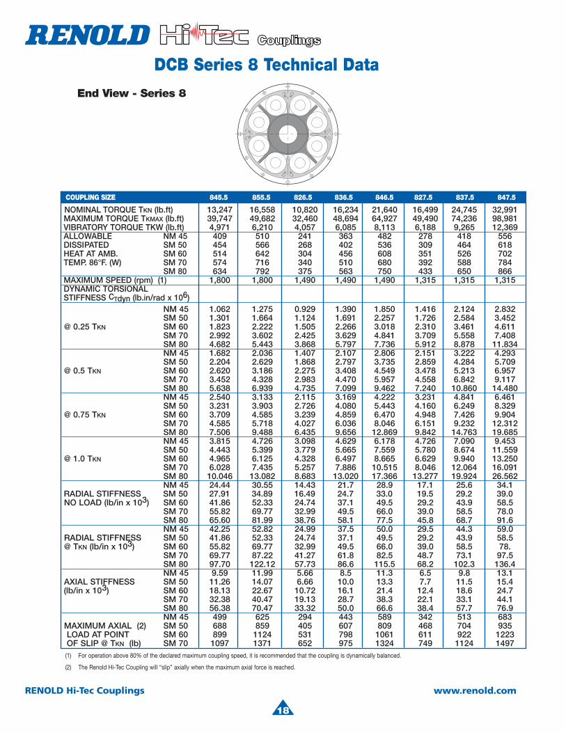
(1) For operation above 80% of the declared maximum coupling speed, it is recommended that the coupling is dynamically balanced.
(2) The Renold Hi-Tec Coupling will “slip” axially when the maximum axial force is reached.
NOMINAL TORQUE TKN (lb.ft) 13,247 16,558 10,820 16,234 21,640 16,499 24,745 32,991 MAXIMUM TORQUE TKMAX (lb.ft) 39,747 49,682 32,460 48,694 64,927 49,490 74,236 98,981 VIBRATORY TORQUE TKW (lb.ft) 4,971 6,210 4,057 6,085 8,113 6,188 9,265 12,369 ALLOWABLE NM 45 409 510 241 363 482 278 418 556 DISSIPATED SM 50 454 566 268 402 536 309 464 618 HEAT AT AMB. SM 60 514 642 304 456 608 351 526 702 TEMP. 86°F. (W) SM 70 574 716 340 510 680 392 588 784 SM 80 634 792 375 563 750 433 650 866 MAXIMUM SPEED (rpm) (1) 1,800 1,800 1,490 1,490 1,490 1,315 1,315 1,315 DYNAMIC TORSIONAL STIFFNESS CTdyn (lb.in/rad x 106)
NM 45 1.062 1.275 0.929 1.390 1.850 1.416 2.124 2.832 SM 50 1.301 1.664 1.124 1.691 2.257 1.726 2.584 3.452 @ 0.25 TKN SM 60 1.823 2.222 1.505 2.266 3.018 2.310 3.461 4.611 SM 70 2.992 3.602 2.425 3.629 4.841 3.709 5.558 7.408 SM 80 4.682 5.443 3.868 5.797 7.736 5.912 8.878 11.834 NM 45 1.682 2.036 1.407 2.107 2.806 2.151 3.222 4.293 SM 50 2.204 2.629 1.868 2.797 3.735 2.859 4.284 5.709 @ 0.5 TKN SM 60 2.620 3.186 2.275 3.408 4.549 3.478 5.213 6.957 SM 70 3.452 4.328 2.983 4.470 5.957 4.558 6.842 9.117 SM 80 5.638 6.939 4.735 7.099 9.462 7.240 10.860 14.480 NM 45 2.540 3.133 2.115 3.169 4.222 3.231 4.841 6.461 SM 50 3.231 3.903 2.726 4.080 5.443 4.160 6.249 8.329 @ 0.75 TKN SM 60 3.709 4.585 3.239 4.859 6.470 4.948 7.426 9.904 SM 70 4.585 5.718 4.027 6.036 8.046 6.151 9.232 12.312 SM 80 7.506 9.488 6.435 9.656 12.869 9.842 14.763 19.685 NM 45 3.815 4.726 3.098 4.629 6.178 4.726 7.090 9.453 SM 50 4.443 5.399 3.779 5.665 7.559 5.780 8.674 11.559 @ 1.0 TKN SM 60 4.965 6.125 4.328 6.497 8.665 6.629 9.940 13.250 SM 70 6.028 7.435 5.257 7.886 10.515 8.046 12.064 16.091 SM 80 10.046 13.082 8.683 13.020 17.366 13.277 19.924 26.562 NM 45 24.44 30.55 14.43 21.7 28.9 17.1 25.6 34.1 RADIAL STIFFNESS SM 50 27.91 34.89 16.49 24.7 33.0 19.5 29.2 39.0 NO LOAD (lb/in x 103) SM 60 41.86 52.33 24.74 37.1 49.5 29.2 43.9 58.5
SM 70 55.82 69.77 32.99 49.5 66.0 39.0 58.5 78.0SM 80 65.60 81.99 38.76 58.1 77.5 45.8 68.7 91.6NM 45 42.25 52.82 24.99 37.5 50.0 29.5 44.3 59.0
RADIAL STIFFNESS SM 50 41.86 52.33 24.74 37.1 49.5 29.2 43.9 58.5 @ TKN (lb/in x 103) SM 60 55.82 69.77 32.99 49.5 66.0 39.0 58.5 78.
SM 70 69.77 87.22 41.27 61.8 82.5 48.7 73.1 97.5SM 80 97.70 122.12 57.73 86.6 115.5 68.2 102.3 136.4NM 45 9.59 11.99 5.66 8.5 11.3 6.5 9.8 13.1
AXIAL STIFFNESS SM 50 11.26 14.07 6.66 10.0 13.3 7.7 11.5 15.4 (lb/in x 103) SM 60 18.13 22.67 10.72 16.1 21.4 12.4 18.6 24.7
SM 70 32.38 40.47 19.13 28.7 38.3 22.1 33.1 44.1SM 80 56.38 70.47 33.32 50.0 66.6 38.4 57.7 76.9NM 45 499 625 294 443 589 342 513 683
MAXIMUM AXIAL (2) SM 50 688 859 405 607 809 468 704 935 LOAD AT POINT SM 60 899 1124 531 798 1061 611 922 1223 OF SLIP @ TKN (lb) SM 70 1097 1371 652 975 1324 749 1124 1497
End View - Series 8
COUPLING SIZE 845.5 855.5 826.5 836.5 846.5 827.5 837.5 847.5
18
4
19
RENOLD Hi-Tec Couplings www.renold.com
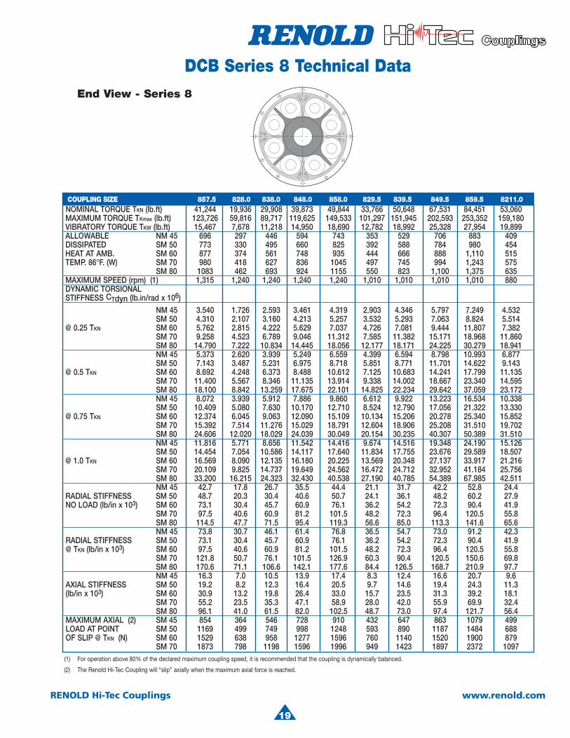
(1) For operation above 80% of the declared maximum coupling speed, it is recommended that the coupling is dynamically balanced.
(2) The Renold Hi-Tec Coupling will “slip” axially when the maximum axial force is reached.
NOMINAL TORQUE TKN (lb.ft) 41,244 19,936 29,908 39,873 49,844 33,766 50,648 67,531 84,451 53,060 MAXIMUM TORQUE TKmax (lb.ft) 123,726 59,816 89,717 119,625 149,533 101,297 151,945 202,593 253,352 159,180 VIBRATORY TORQUE TKW (lb.ft) 15,467 7,678 11,218 14,950 18,690 12,782 18,992 25,328 27,954 19,899 ALLOWABLE NM 45 696 297 446 594 743 353 529 706 883 409 DISSIPATED SM 50 773 330 495 660 825 392 588 784 980 454 HEAT AT AMB. SM 60 877 374 561 748 935 444 666 888 1,110 515 TEMP. 86°F. (W) SM 70 980 418 627 836 1045 497 745 994 1,243 575 SM 80 1083 462 693 924 1155 550 823 1,100 1,375 635 MAXIMUM SPEED (rpm) (1) 1,315 1,240 1,240 1,240 1,240 1,010 1,010 1,010 1,010 880 DYNAMIC TORSIONAL STIFFNESS CTdyn (lb.in/rad x 106)
NM 45 3.540 1.726 2.593 3.461 4.319 2.903 4.346 5.797 7.249 4.532 SM 50 4.310 2.107 3.160 4.213 5.257 3.532 5.293 7.063 8.824 5.514 @ 0.25 TKN SM 60 5.762 2.815 4.222 5.629 7.037 4.726 7.081 9.444 11.807 7.382 SM 70 9.258 4.523 6.789 9.046 11.312 7.585 11.382 15.171 18.968 11.860 SM 80 14.790 7.222 10.834 14.445 18.056 12.177 18.171 24.225 30.279 18.941 NM 45 5.373 2.620 3.939 5.249 6.559 4.399 6.594 8.798 10.993 6.877 SM 50 7.143 3.487 5.231 6.975 8.718 5.851 8.771 11.701 14.622 9.143 @ 0.5 TKN SM 60 8.692 4.248 6.373 8.488 10.612 7.125 10.683 14.241 17.799 11.135 SM 70 11.400 5.567 8.346 11.135 13.914 9.338 14.002 18.667 23.340 14.595 SM 80 18.100 8.842 13.259 17.675 22.101 14.825 22.234 29.642 37.059 23.172 NM 45 8.072 3.939 5.912 7.886 9.860 6.612 9.922 13.223 16.534 10.338 SM 50 10.409 5.080 7.630 10.170 12.710 8.524 12.790 17.056 21.322 13.330 @ 0.75 TKN SM 60 12.374 6.045 9.063 12.090 15.109 10.134 15.206 20.278 25.340 15.852 SM 70 15.392 7.514 11.276 15.029 18.791 12.604 18.906 25.208 31.510 19.702 SM 80 24.606 12.020 18.029 24.039 30.049 20.154 30.235 40.307 50.389 31.510 NM 45 11.816 5.771 8.656 11.542 14.416 9.674 14.516 19.348 24.190 15.126 SM 50 14.454 7.054 10.586 14.117 17.640 11.834 17.755 23.676 29.589 18.507 @ 1.0 TKN SM 60 16.569 8.090 12.135 16.180 20.225 13.569 20.348 27.137 33.917 21.216 SM 70 20.109 9.825 14.737 19.649 24.562 16.472 24.712 32.952 41.184 25.756 SM 80 33.200 16.215 24.323 32.430 40.538 27.190 40.785 54.389 67.985 42.511 NM 45 42.7 17.8 26.7 35.5 44.4 21.1 31.7 42.2 52.8 24.4 RADIAL STIFFNESS SM 50 48.7 20.3 30.4 40.6 50.7 24.1 36.1 48.2 60.2 27.9 NO LOAD (lb/in x 103) SM 60 73.1 30.4 45.7 60.9 76.1 36.2 54.2 72.3 90.4 41.9
SM 70 97.5 40.6 60.9 81.2 101.5 48.2 72.3 96.4 120.5 55.8SM 80 114.5 47.7 71.5 95.4 119.3 56.6 85.0 113.3 141.6 65.6NM 45 73.8 30.7 46.1 61.4 76.8 36.5 54.7 73.0 91.2 42.3
RADIAL STIFFNESS SM 50 73.1 30.4 45.7 60.9 76.1 36.2 54.2 72.3 90.4 41.9@ TKN (lb/in x 103) SM 60 97.5 40.6 60.9 81.2 101.5 48.2 72.3 96.4 120.5 55.8
SM 70 121.8 50.7 76.1 101.5 126.9 60.3 90.4 120.5 150.6 69.8SM 80 170.6 71.1 106.6 142.1 177.6 84.4 126.5 168.7 210.9 97.7NM 45 16.3 7.0 10.5 13.9 17.4 8.3 12.4 16.6 20.7 9.6
AXIAL STIFFNESS SM 50 19.2 8.2 12.3 16.4 20.5 9.7 14.6 19.4 24.3 11.3(lb/in x 103) SM 60 30.9 13.2 19.8 26.4 33.0 15.7 23.5 31.3 39.2 18.1
SM 70 55.2 23.5 35.3 47.1 58.9 28.0 42.0 55.9 69.9 32.4SM 80 96.1 41.0 61.5 82.0 102.5 48.7 73.0 97.4 121.7 56.4
MAXIMUM AXIAL (2) SM 45 854 364 546 728 910 432 647 863 1079 499LOAD AT POINT SM 50 1169 499 749 998 1248 593 890 1187 1484 688OF SLIP @ TKN (N) SM 60 1529 638 958 1277 1596 760 1140 1520 1900 879
SM 70 1873 798 1198 1596 1996 949 1423 1897 2372 1097
End View - Series 8
DCB Series 8 Technical Data
COUPLING SIZE 857.5 828.0 838.0 848.0 858.0 829.5 839.5 849.5 859.5 8211.0
19

20
RENOLD Hi-Tec Couplings www.renold.com
DCB Design VariationsThe DCB coupling can be adapted to meet customer requirements, as can be seen from the design variations shown below. For a more comprehensive list contact Renold Hi-Tec.
Cardan Shaft Coupling Universal Joint Shaft Coupling
Stub Shaft Coupling Adaptor Plate Coupling
Clutch Coupling Limited End Float Coupling
Coupling for use with a universal joint shaft. The coupling has radial and axial bearings to accept the sinusoidal loads from the universal joint shaft.
Cardan shaft coupling to give high misalignment capability, low axial and angular stiffness and high noise attenuation.
Limited end float coupling for use on applications where axial restraint is required,such as alternators with sleeve bearings.
Stub shaft coupling for flywheel to flangeapplication or when increased distance between the driving and driven machines is required.
Adaptor plate coupling for adapting the standard DCB coupling to meet customer requirements.
Clutch coupling to allow the drive to be engaged and disengaged.
20
4
21
RENOLD Hi-Tec Couplings www.renold.com
22
RENOLD Hi-Tec Couplings www.renold.com
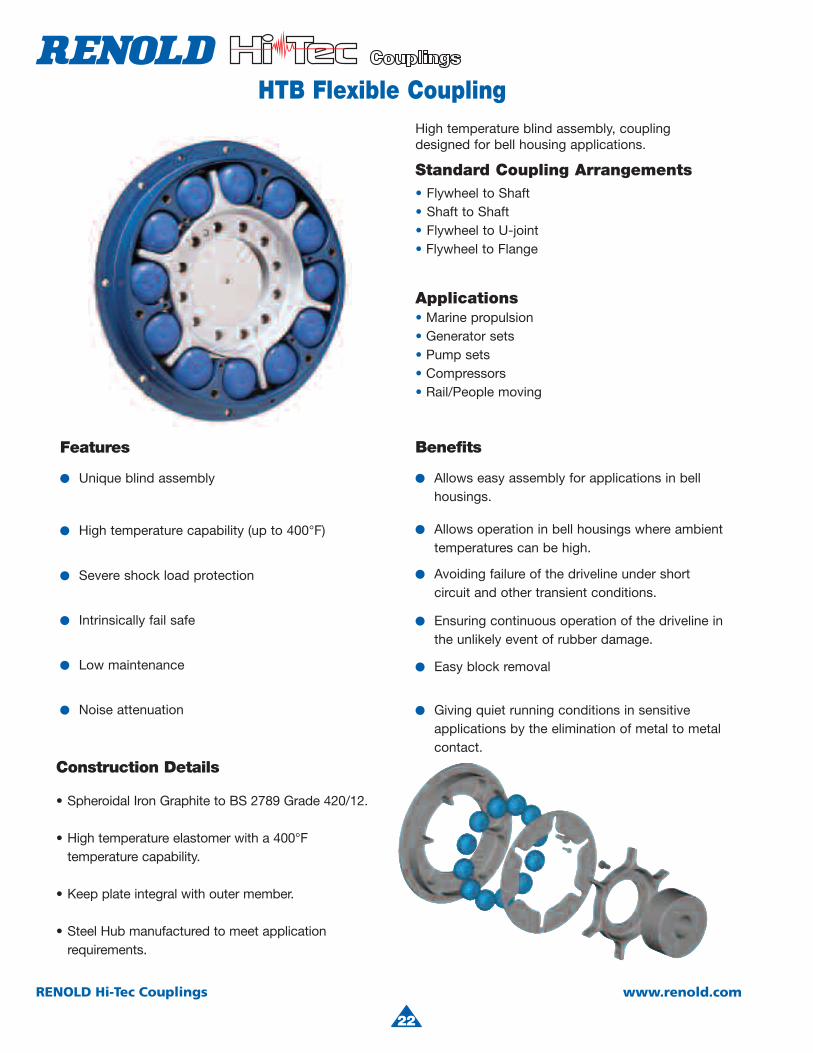
HTB Flexible Coupling
Features
● Unique blind assembly
● High temperature capability (up to 400°F)
● Severe shock load protection
● Intrinsically fail safe
● Low maintenance
● Noise attenuation
Construction Details
• Spheroidal Iron Graphite to BS 2789 Grade 420/12.
• High temperature elastomer with a 400°F temperature capability.
• Keep plate integral with outer member.
• Steel Hub manufactured to meet application requirements.
High temperature blind assembly, coupling designed for bell housing applications.
Standard Coupling Arrangements• Flywheel to Shaft• Shaft to Shaft• Flywheel to U-joint• Flywheel to Flange
Applications• Marine propulsion• Generator sets• Pump sets• Compressors• Rail/People moving
Benefits
● Allows easy assembly for applications in bell housings.
● Allows operation in bell housings where ambient temperatures can be high.
● Avoiding failure of the driveline under short circuit and other transient conditions.
● Ensuring continuous operation of the driveline in the unlikely event of rubber damage.
● Easy block removal
● Giving quiet running conditions in sensitive applications by the elimination of metal to metal contact.
22
Features
● Unique blind assembly
● High temperature capability (up to 400°F)
● Severe shock load protection
● Intrinsically fail safe
● Low maintenance
● Noise attenuation
Construction Details
• Spheroidal Iron Graphite to BS 2789 Grade 420/12.
• High temperature elastomer with a 400°F temperature capability.
• Keep plate integral with outer member.
• Steel Hub manufactured to meet application requirements.
High temperature blind assembly, coupling designed for bell housing applications.
Standard Coupling Arrangements• Flywheel to Shaft• Shaft to Shaft• Flywheel to U-joint• Flywheel to Flange
Applications• Marine propulsion• Generator sets• Pump sets• Compressors• Rail/People moving
Benefits
● Allows easy assembly for applications in bellhousings.
● Allows operation in bell housings where ambient temperatures can be high.
● Avoiding failure of the driveline under short circuit and other transient conditions.
● Ensuring continuous operation of the driveline in the unlikely event of rubber damage.
● Easy block removal
● Giving quiet running conditions in sensitiveapplications by the elimination of metal to metalcontact.
4
23
RENOLD Hi-Tec Couplings www.renold.com
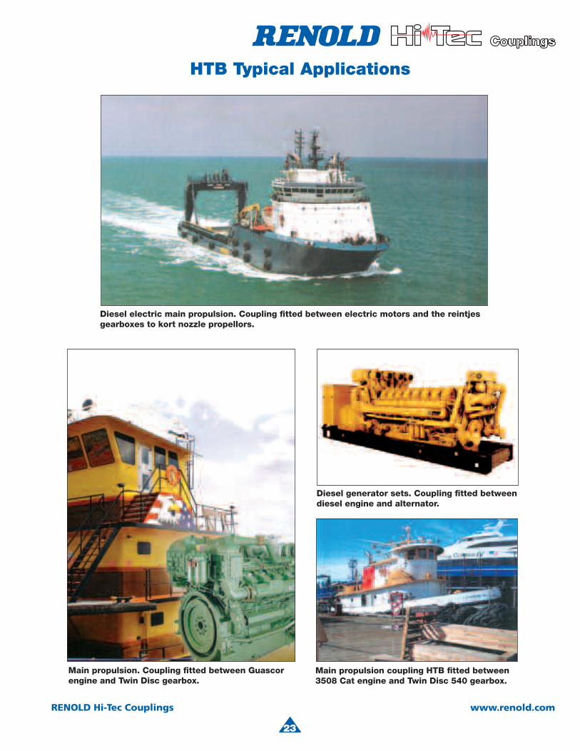
HTB Typical Applications
23
Diesel electric main propulsion. Coupling fitted between electric motors and the reintjes gearboxes to kort nozzle propellors.
Main propulsion coupling HTB fi tted between3508 Cat engine and Twin Disc 540 gearbox.
Main propulsion. Coupling fitted between Guascor engine and Twin Disc gearbox.
Diesel generator sets. Coupling fitted betweendiesel engine and alternator.
24
RENOLD Hi-Tec Couplings www.renold.com
Y EA F GD
LB
J
Q x R
W1J1
U x V
S x TW-3
C
M x NW2J2
A F G GY E
Q x R
W1J1
U x V
S x T
W3J3
L
D
BJ
B2
C
M x NW2J2
Y EA F GD
LB
J
Q x R
W1J1
U x V
S x T
W3J3C
M x NW2J2
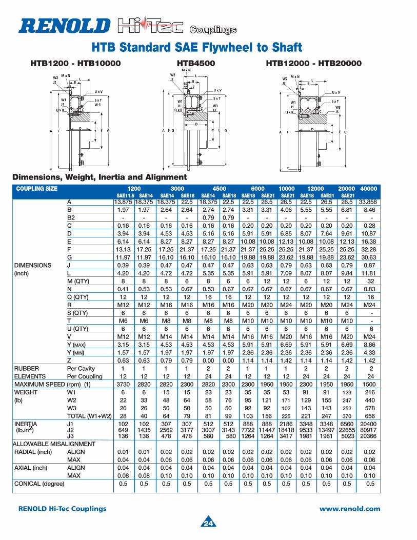
HTB Standard SAE Flywheel to ShaftHTB1200 - HTB10000
Dimensions, Weight, Inertia and Alignment
HTB4500 HTB12000 - HTB20000
A 13.875 18.375 18.375 22.5 18.375 22.5 22.5 26.5 26.5 22.5 26.5 26.5 33.858 B 1.97 1.97 2.64 2.64 2.74 2.74 3.31 3.31 4.06 5.55 5.55 6.81 8.46 B2 - - - - 0.79 0.79 - - - - - - -
C 0.16 0.16 0.16 0.16 0.16 0.16 0.20 0.20 0.20 0.20 0.20 0.20 0.28 D 3.94 3.94 4.53 4.53 5.16 5.16 5.91 5.91 6.85 8.07 7.64 9.61 10.87 E 6.14 6.14 8.27 8.27 8.27 8.27 10.08 10.08 12.13 10.08 10.08 12.13 16.38 F 13.13 17.25 17.25 21.37 17.25 21.37 21.37 25.25 25.25 21.37 25.25 25.25 32.28 G 11.97 11.97 16.10 16.10 16.10 16.10 19.88 19.88 23.62 19.88 19.88 23.62 30.63 DIMENSIONS J 0.39 0.39 0.47 0.47 0.47 0.47 0.63 0.63 0.79 0.63 0.63 0.79 0.87 (inch) L 4.20 4.20 4.72 4.72 5.35 5.35 5.91 5.91 7.09 8.07 8.07 9.84 11.81
M (QTY) 8 8 8 6 8 6 6 12 12 6 12 12 32N 0.41 0.53 0.53 0.67 0.53 0.67 0.67 0.67 0.67 0.67 0.67 0.67 0.83
Q (QTY) 12 12 12 12 16 16 12 12 12 12 12 12 16R M12 M12 M16 M16 M16 M16 M20 M20 M24 M20 M20 M24 M24
S (QTY) 6 6 6 6 6 6 6 6 6 6 6 6 -T M6 M6 M8 M8 M8 M8 M10 M10 M10 M10 M10 M10 -
U (QTY) 6 6 6 6 6 6 6 6 6 6 6 6 6V M12 M12 M14 M14 M14 M14 M16 M16 M20 M16 M16 M20 M24
Y (MAX) 3.15 3.15 4.53 4.53 4.53 4.53 5.91 5.91 6.69 5.91 5.91 6.69 8.66 Y (MIN) 1.57 1.57 1.97 1.97 1.97 1.97 2.36 2.36 2.36 2.36 2.36 2.36 4.33 Z 0.63 0.63 0.79 0.79 0.00 0.00 1.14 1.14 1.42 1.14 1.14 1.42 1.42 RUBBER Per Cavity 1 1 1 1 2 2 1 1 1 2 2 2 2 ELEMENTS Per Coupling 12 12 12 12 24 24 12 12 12 24 24 24 24MAXIMUM SPEED (rpm) (1) 3730 2820 2820 2300 2820 2300 2300 1950 1950 2300 1950 1950 1500
WEIGHT W1 6 6 15 15 23 23 35 35 53 91 91 123 216(lb) W2 22 33 48 64 58 76 95 121 171 129 155 247 440
W3 26 26 50 50 50 50 92 92 102 143 143 252 578TOTAL (W1+W2) 28 40 64 79 81 99 103 156 225 221 247 370 656
INERTIA J1 102 102 307 307 512 512 888 888 2186 3348 3348 6560 20400(lb.in2) J2 649 1435 2562 3177 3007 3143 7722 11447 18418 9533 13497 22655 80917
J3 136 136 478 478 580 580 1264 1264 3417 1981 1981 5023 20366 ALLOWABLE MISALIGNMENTRADIAL (inch) ALIGN 0.01 0.01 0.02 0.02 0.02 0.02 0.02 0.02 0.02 0.02 0.02 0.02 0.02
MAX 0.04 0.04 0.06 0.06 0.06 0.06 0.06 0.06 0.06 0.06 0.06 0.06 0.06AXIAL (inch) ALIGN 0.04 0.04 0.04 0.04 0.04 0.04 0.04 0.04 0.04 0.04 0.04 0.04 0.04
MAX 0.08 0.08 0.10 0.10 0.10 0.10 0.10 0.10 0.10 0.10 0.10 0.10 0.10CONICAL (degree) 0.5 0.5 0.5 0.5 0.5 0.5 0.5 0.5 0.5 0.5 0.5 0.5 0.5
COUPLING SIZE 1200 3000 4500 6000 10000 12000 20000 40000 SAE11.5 SAE14 SAE14 SAE18 SAE14 SAE18 SAE18 SAE21 SAE21 SAE18 SAE21 SAE21
24
4
25
RENOLD Hi-Tec Couplings www.renold.com
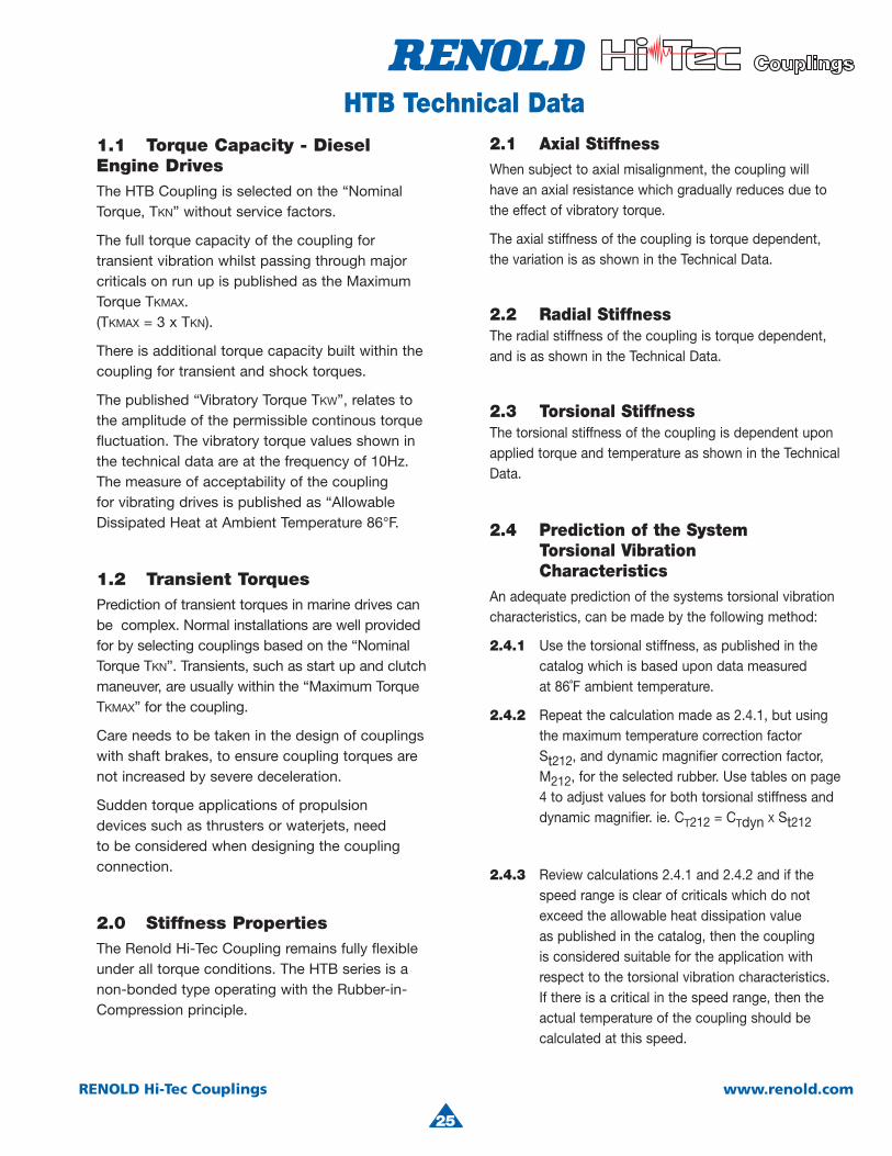
HTB Technical Data2.1 Axial StiffnessWhen subject to axial misalignment, the coupling will have an axial resistance which gradually reduces due to the effect of vibratory torque.
The axial stiffness of the coupling is torque dependent, the variation is as shown in the Technical Data.
2.2 Radial StiffnessThe radial stiffness of the coupling is torque dependent, and is as shown in the Technical Data.
2.3 Torsional StiffnessThe torsional stiffness of the coupling is dependent upon applied torque and temperature as shown in the Technical Data.
2.4 Prediction of the System Torsional Vibration CharacteristicsAn adequate prediction of the systems torsional vibration characteristics, can be made by the following method:
2.4.1 Use the torsional stiffness, as published in the catalog which is based upon data measured at 86˚F ambient temperature.
2.4.2 Repeat the calculation made as 2.4.1, but using the maximum temperature correction factor St212, and dynamic magnifier correction factor, M212, for the selected rubber. Use tables on page 4 to adjust values for both torsional stiffness and dynamic magnifier. ie. CT212 = CTdyn X St212
2.4.3 Review calculations 2.4.1 and 2.4.2 and if the speed range is clear of criticals which do not exceed the allowable heat dissipation value as published in the catalog, then the coupling is considered suitable for the application with respect to the torsional vibration characteristics. If there is a critical in the speed range, then the actual temperature of the coupling should becalculated at this speed.
1.1 Torque Capacity - DieselEngine DrivesThe HTB Coupling is selected on the “Nominal Torque, TKN” without service factors.
The full torque capacity of the coupling for transient vibration whilst passing through major criticals on run up is published as the MaximumTorque TKMAX.(TKMAX = 3 x TKN).
There is additional torque capacity built within the coupling for transient and shock torques.
The published “Vibratory Torque TKW”, relates to the amplitude of the permissible continous torque fluctuation. The vibratory torque values shown in the technical data are at the frequency of 10Hz. The measure of acceptability of the coupling for vibrating drives is published as “Allowable Dissipated Heat at Ambient Temperature 86°F.
1.2 Transient TorquesPrediction of transient torques in marine drives can be complex. Normal installations are well provided for by selecting couplings based on the “Nominal Torque TKN”. Transients, such as start up and clutch maneuver, are usually within the “Maximum TorqueTKMAX” for the coupling.
Care needs to be taken in the design of couplingswith shaft brakes, to ensure coupling torques are not increased by severe deceleration.
Sudden torque applications of propulsion devices such as thrusters or waterjets, needto be considered when designing the coupling connection.
2.0 Stiffness PropertiesThe Renold Hi-Tec Coupling remains fully flexible under all torque conditions. The HTB series is a non-bonded type operating with the Rubber-in-Compression principle.
25

26
RENOLD Hi-Tec Couplings www.renold.com
HTB Technical Data
Si 70 is considered “standard”
RubberGrade
Si 70
DynamicMagnifier
(M86)
7.5
RelativeDamping
ψ86
0.83
Si 70 is considered “standard”
2.6 Temperature Correction Factor - Si-70
2.5 Prediction of the ActualCouplingTemperature and
Torsional Stiffness2.5.1 Use the torsional stiffness as published in the
catalog. This is based upon data measured at 86˚F and the dynamic magnifier at 86˚F (M86)
2.5.2 Compare the synthesis value of the calculated heat load in the coupling (PK) at the speed ofinterest, to the “Allowable Heat Dissipation”(PKW).
The coupling temperature rise = ∆F∆F = Tempcoup = x 306
The coupling temperature = ϑϑ = Tempcoup + Ambient Temp.
2.5.3 Calculate the temperature correction factor, St,
from 2.6 (if the coupling temperature > 212ºF, then use St212). Calculate the dynamic Magnifieras per 2.7. Repeat the calculation with the newvalue of coupling stiffness and dynamic magnifier
2.5.4 Calculate the coupling temperature as per 2.5.2 Repeat calculation until the coupling temperature agrees with the correction factors for torsional stiffness and dynamic magnifier used in the calculation.
PK
PKW( )
MT = M86St
ψT = ψ86 x St
RubberGrade
Si 70
Tempmax
°F
212
St
St212 = 0.79
Si 70 is considered “standard”
RubberGrade
Si 70
DynamicMagnifierat 86ºF(M86)
7.5
DynamicMagnifierat 212ºF(M212)
9.70
77 122 167 212 257 302 347 392
R
Tem
per
atur
eC
orre
ctio
nFa
ctor
St
0.4
0.5
0.6
0.7
0.8
0.9
1
1.1
2.7 Dynamic Magnifier Correction Factor
The Dynamic Magnifier of the rubber is subject to temperature variation in the same way as the torsional stiffness.
26
ϑ
Rubber Temperature (ϑ) ˚F
4
27
RENOLD Hi-Tec Couplings www.renold.com
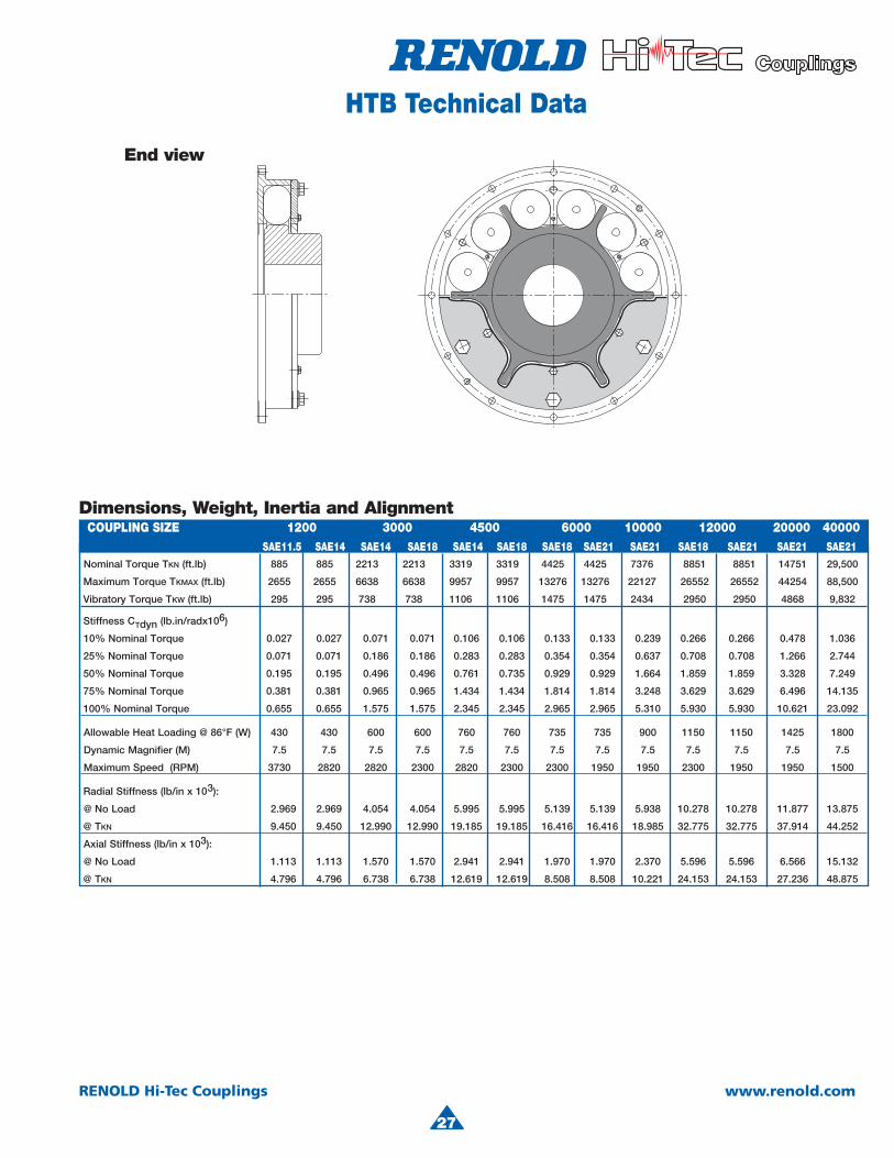
HTB Technical Data
Dimensions, Weight, Inertia and Alignment
End view
Nominal Torque TKN (ft.lb) 885 885 2213 2213 3319 3319 4425 4425 7376 8851 8851 14751 29,500
Maximum Torque TKMAX (ft.lb) 2655 2655 6638 6638 9957 9957 13276 13276 22127 26552 26552 44254 88,500
Vibratory Torque TKW (ft.lb) 295 295 738 738 1106 1106 1475 1475 2434 2950 2950 4868 9,832
Stiffness CTdyn (lb.in/radx106)
10% Nominal Torque 0.027 0.027 0.071 0.071 0.106 0.106 0.133 0.133 0.239 0.266 0.266 0.478 1.036
25% Nominal Torque 0.071 0.071 0.186 0.186 0.283 0.283 0.354 0.354 0.637 0.708 0.708 1.266 2.744
50% Nominal Torque 0.195 0.195 0.496 0.496 0.761 0.735 0.929 0.929 1.664 1.859 1.859 3.328 7.249
75% Nominal Torque 0.381 0.381 0.965 0.965 1.434 1.434 1.814 1.814 3.248 3.629 3.629 6.496 14.135
100% Nominal Torque 0.655 0.655 1.575 1.575 2.345 2.345 2.965 2.965 5.310 5.930 5.930 10.621 23.092
Allowable Heat Loading @ 86°F (W) 430 430 600 600 760 760 735 735 900 1150 1150 1425 1800
Dynamic Magnifier (M) 7.5 7.5 7.5 7.5 7.5 7.5 7.5 7.5 7.5 7.5 7.5 7.5 7.5
Maximum Speed (RPM) 3730 2820 2820 2300 2820 2300 2300 1950 1950 2300 1950 1950 1500
Radial Stiffness (lb/in x 103):
@ No Load 2.969 2.969 4.054 4.054 5.995 5.995 5.139 5.139 5.938 10.278 10.278 11.877 13.875
@ TKN 9.450 9.450 12.990 12.990 19.185 19.185 16.416 16.416 18.985 32.775 32.775 37.914 44.252
Axial Stiffness (lb/in x 103):
@ No Load 1.113 1.113 1.570 1.570 2.941 2.941 1.970 1.970 2.370 5.596 5.596 6.566 15.132
@ TKN 4.796 4.796 6.738 6.738 12.619 12.619 8.508 8.508 10.221 24.153 24.153 27.236 48.875
COUPLING SIZE 1200 3000 4500 6000 10000 12000 20000 40000 SAE11.5 SAE14 SAE14 SAE18 SAE14 SAE18 SAE18 SAE21 SAE21 SAE18 SAE21 SAE21 SAE21
27
28
RENOLD Hi-Tec Couplings www.renold.com
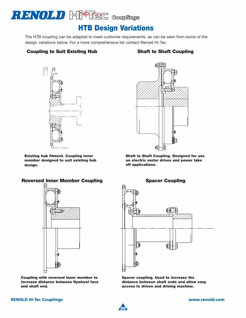
HTB Design VariationsThe HTB coupling can be adapted to meet customer requirements, as can be seen from some of the design variations below. For a more comprehensive list contact Renold Hi-Tec.
Coupling to Suit Existing Hub Shaft to Shaft Coupling
Reversed Inner Member Coupling Spacer Coupling
Existing hub fitment. Coupling inner member designed to suit existing hub design.
Shaft to Shaft Coupling. Designed for use on electric motor drives and power take off applications.
Coupling with reversed inner member to increase distance between flywheel faceand shaft end.
Spacer coupling. Used to increase the distance between shaft ends and allow easy access to driven and driving machine.
28

4
29
RENOLD Hi-Tec Couplings www.renold.com

30
RENOLD Hi-Tec Couplings www.renold.com
RB Flexible CouplingGeneral purpose, cost effective coupling range manufactured from SG iron for torques up to 30,240 lb-ft.
Standard Coupling Arrangements• Shaft to shaft• Shaft to shaft with increased shaft engagement• Flywheel to shaft• Flywheel to shaft with increased shaft engagement
Applications• Generator sets• Pump sets• Compressors• Wind turbines• Metal manufacture• Bulk handling• Pulp and paper industry• Marine propulsion• General heavy duty industrial applications
Features
● Intrinsically fail safe
● Control of resonant torsional vibration
● Maintenance free
● Severe shock load protection
● Misalignment capability
● Zero backlash
● Low cost
● Selection of Rubber
Construction details• Spheroidal graphite iron to BS 2789 Grade 420/12
• Separate rubber elements with a choice ofgrade and hardness, styrene butadiene with 70 shore hardness (SM70) is standard.
• Rubber elements which are totally enclosed and loaded in compression.
Benefits
● Ensures continuous operation of the driveline in the unlikely event of rubber damage.
● Achieves low vibratory loads in the driveline components by selection of optimum stiffness characteristics.
● No lubrication or adjustment required resulting in low running costs.
● Avoids failure of the driveline under short circuit and other transient conditions.
● Allows axial, angular and radial misalignments between the driving and driven machines.
● Eliminates torque amplifications through pre-compression of the rubber elements.
● The RB coupling gives the lowest lifetime cost.
● Variety of rubber materials and hardness are available for optimum reduction of drive vibration and maximun block life.
4
31
RENOLD Hi-Tec Couplings www.renold.com
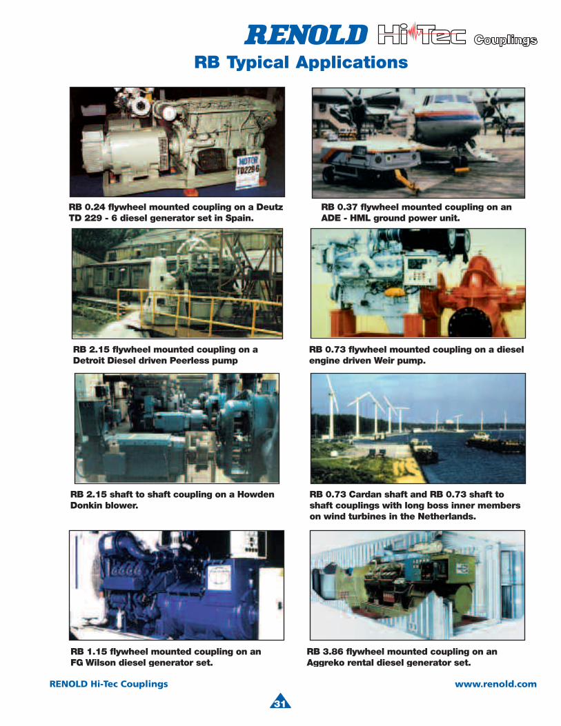
RB 0.24 flywheel mounted coupling on a DeutzTD 229 - 6 diesel generator set in Spain.
RB 2.15 flywheel mounted coupling on a Detroit Diesel driven Peerless pump
RB 2.15 shaft to shaft coupling on a HowdenDonkin blower.
RB 0.37 flywheel mounted coupling on an ADE - HML ground power unit.
RB 0.73 flywheel mounted coupling on a dieselengine driven Weir pump.
RB 0.73 Cardan shaft and RB 0.73 shaft to shaft couplings with long boss inner members on wind turbines in the Netherlands.
RB 3.86 flywheel mounted coupling on an Aggreko rental diesel generator set.
RB 1.15 flywheel mounted coupling on anFG Wilson diesel generator set.
31
RB Typical Applications
32
RENOLD Hi-Tec Couplings www.renold.com
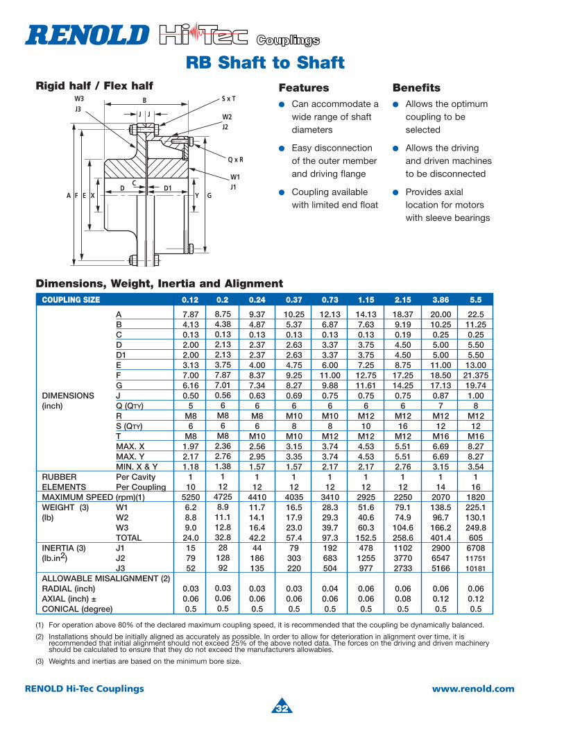
RB Shaft to ShaftFeatures● Can accommodate a
wide range of shaft diameters
● Easy disconnectionof the outer memberand driving flange
● Coupling availablewith limited end float
Benefits● Allows the optimum
coupling to beselected
● Allows the driving and driven machinesto be disconnected
● Provides axiallocation for motorswith sleeve bearings
(1) For operation above 80% of the declared maximum coupling speed, it is recommended that the coupling be dynamically balanced.
(2) Installations should be initially aligned as accurately as possible. In order to allow for deterioration in alignment over time, it is recommended that initial alignment should not exceed 25% of the above noted data. The forces on the driving and driven machinery should be calculated to ensure that they do not exceed the manufacturers allowables.
(3) Weights and inertias are based on the minimum bore size.
Rigid half / Flex half
Dimensions, Weight, Inertia and AlignmentCOUPLING SIZE 0.12 0.2 0.24 0.37 0.73 1.15 2.15 3.86 5.5
A 7.87 9.37 10.25 12.13 14.13 18.37 20.00 22.5B 4.13 4.87 5.37 6.87 7.63 9.19 10.25 11.25
C 0.13 0.13 0.13 0.13 0.13 0.19 0.25 0.25D 2.00 2.37 2.63 3.37 3.75 4.50 5.00 5.50D1 2.00 2.37 2.63 3.37 3.75 4.50 5.00 5.50E 3.13 4.00 4.75 6.00 7.25 8.75 11.00 13.00
F 7.00 8.37 9.25 11.00 12.75 17.25 18.50 21.375G 6.16 7.34 8.27 9.88 11.61 14.25 17.13 19.74
DIMENSIONS J 0.50 0.63 0.69 0.75 0.75 0.75 0.87 1.00(inch) Q (QTY) 5 6 6 6 6 6 7 8
R M8 M8 M10 M10 M12 M12 M12 M12 S (QTY) 6 6 8 8 10 16 12 12
T M8 M10 M10 M12 M12 M12 M16 M16 MAX. X 1.97 2.56 3.15 3.74 4.53 5.51 6.69 8.27
MAX. Y 2.17 2.95 3.35 3.74 4.53 5.51 6.69 8.27MIN. X & Y 1.18 1.57 1.57 2.17 2.17 2.76 3.15 3.54
RUBBER Per Cavity 1 1 1 1 1 1 1 1ELEMENTS Per Coupling 10 12 12 12 12 12 14 16MAXIMUM SPEED (rpm)(1) 5250 4410 4035 3410 2925 2250 2070 1820
WEIGHT (3) W1 6.2 11.7 16.5 28.3 51.6 79.1 138.5 225.1(lb) W2 8.8 14.1 17.9 29.3 40.6 74.9 96.7 130.1
W3 9.0 16.4 23.0 39.7 60.3 104.6 166.2 249.8TOTAL 24.0 42.2 57.4 97.3 152.5 258.6 401.4 605
INERTIA (3) J1 15 44 79 192 478 1102 2900 6708(lb.in2) J2 79 186 303 683 1255 3770 6547 11751
J3 52 135 220 504 977 2733 5166 10181ALLOWABLE MISALIGNMENT (2)RADIAL (inch) 0.03 0.03 0.03 0.04 0.06 0.06 0.06 0.06AXIAL (inch) ± 0.06 0.06 0.06 0.06 0.06 0.08 0.12 0.12CONICAL (degree) 0.5 0.5 0.5 0.5 0.5 0.5 0.5 0.5
8.754.380.132.132.133.757.877.010.56
6M86
M82.362.761.38
112
47258.911.112.832.82812892
0.030.060.5

4
33
RENOLD Hi-Tec Couplings www.renold.com
RB Shaft to Shaft with Increased Shaft Engagement
Features● Long boss inner
member
Benefits● Allows small
diameter, long length shafts to be used
● Reduces key stress
● Allows increased distances betweenshaft ends
● Full shaft engagement avoids the need for spacercollars
Rigid half / Flex half
Dimensions, Weight, Inertia and Alignment
8.755.992.250.132.133.743.757.877.010.56
6M86
M82.362.761.38
112
472514.211.112.838.141
12892
0.030.060.5
COUPLING SIZE 0.12 0.2 0.24 0.37 0.73 1.15 2.15 3.86 5.5
A 7.87 9.37 10.25 12.13 14.13 18.37 20.00 22.50 B1 5.47 6.83 7.48 9.21 10.57 12.17 13.52 15.20 B2 2.13 2.50 2.75 3.50 3.87 4.69 5.25 5.75 C 0.13 0.13 0.13 0.13 0.13 0.19 0.25 0.25 D 2.00 2.37 2.63 3.37 3.75 4.50 5.00 5.50 D2 3.35 4.33 4.72 5.71 6.69 7.48 8.27 9.45 E 3.13 4.00 4.75 6.00 7.25 8.75 11.00 13.00 F 7.00 8.37 9.25 11.00 12.75 17.25 18.50 21.375 G 6.16 7.34 8.27 9.88 11.61 14.25 17.13 19.74 DIMENSIONS J 0.50 0.63 0.69 0.75 0.75 0.75 0.87 1.00 (inch) Q (QTY) 5 6 6 6 6 6 7 8
R M8 M8 M10 M10 M12 M12 M12 M12 S (QTY) 6 6 8 8 10 16 12 12
T M8 M10 M10 M12 M12 M12 M16 M16 MAX. X 1.97 2.56 3.15 3.74 4.53 5.51 6.69 8.27 MAX. Y 2.17 2.95 3.35 3.74 4.53 5.51 6.69 8.27 MIN. X & Y 1.18 1.57 1.57 2.17 2.17 2.76 3.15 3.54 RUBBER PER CAVITY 1 1 1 1 1 1 1 1
ELEMENTS PER COUPLING 10 12 12 12 12 12 14 16MAXIMUM SPEED (rpm)(1) 5250 4410 4035 3410 2925 2250 2070 1820WEIGHT (3) W1 9.3 19.1 26.1 42.8 77.8 118.6 210.5 358.9(lb) W2 8.8 14.1 17.9 29.3 40.6 74.9 96.7 130.1
W3 9.0 16.4 23.0 39.7 60.3 104.6 166.2 249.8TOTAL 27.1 49.6 67 111.8 178.7 298.1 473.4 738.8
INERTIA (3) J1 20 65 111 263 647 1485 4043 9893(lb.in2) J2 79 186 303 683 1255 3770 6547 11751
J3 52 135 220 504 977 2733 5166 10181 ALLOWABLE MISALIGNMENT (2)
RADIAL (inch) 0.03 0.03 0.03 0.04 0.06 0.06 0.06 0.06AXIAL (inch) ± 0.06 0.06 0.06 0.06 0.06 0.08 0.12 0.12CONICAL (degree) 0.5 0.5 0.5 0.5 0.5 0.5 0.5 0.5
34
RENOLD Hi-Tec Couplings www.renold.com
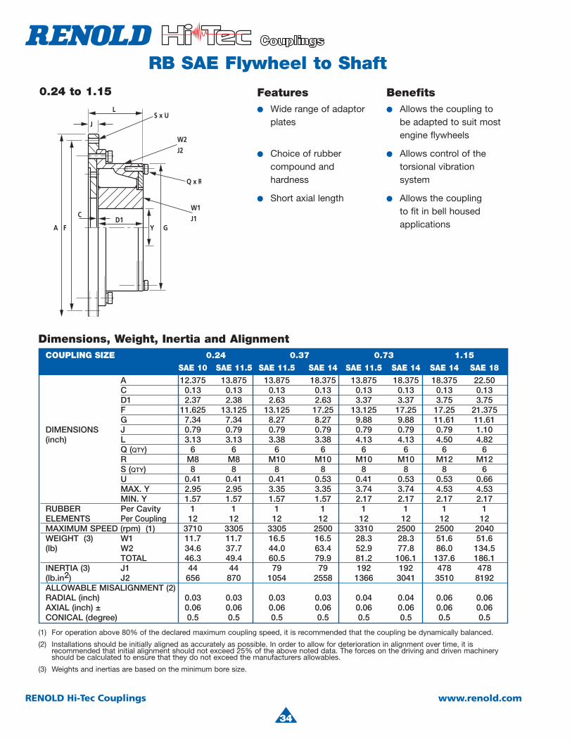
RB SAE Flywheel to Shaft0.24 to 1.15 Features
● Wide range of adaptor plates
● Choice of rubbercompound andhardness
● Short axial length
Benefits● Allows the coupling to
be adapted to suit most engine flywheels
● Allows control of the torsional vibration system
● Allows the coupling to fit in bell housedapplications
Dimensions, Weight, Inertia and Alignment
(1) For operation above 80% of the declared maximum coupling speed, it is recommended that the coupling be dynamically balanced.
(2) Installations should be initially aligned as accurately as possible. In order to allow for deterioration in alignment over time, it is recommended that initial alignment should not exceed 25% of the above noted data. The forces on the driving and driven machinery should be calculated to ensure that they do not exceed the manufacturers allowables.
(3) Weights and inertias are based on the minimum bore size.
COUPLING SIZE 0.24 0.37 0.73 1.15
SAE 10 SAE 11.5 SAE 11.5 SAE 14 SAE 11.5 SAE 14 SAE 14 SAE 18
A 12.375 13.875 13.875 18.375 13.875 18.375 18.375 22.50C 0.13 0.13 0.13 0.13 0.13 0.13 0.13 0.13D1 2.37 2.38 2.63 2.63 3.37 3.37 3.75 3.75F 11.625 13.125 13.125 17.25 13.125 17.25 17.25 21.375
G 7.34 7.34 8.27 8.27 9.88 9.88 11.61 11.61DIMENSIONS J 0.79 0.79 0.79 0.79 0.79 0.79 0.79 1.10(inch) L 3.13 3.13 3.38 3.38 4.13 4.13 4.50 4.82
Q (QTY) 6 6 6 6 6 6 6 6R M8 M8 M10 M10 M10 M10 M12 M12S (QTY) 8 8 8 8 8 8 8 6U 0.41 0.41 0.41 0.53 0.41 0.53 0.53 0.66MAX. Y 2.95 2.95 3.35 3.35 3.74 3.74 4.53 4.53MIN. Y 1.57 1.57 1.57 1.57 2.17 2.17 2.17 2.17
RUBBER Per Cavity 1 1 1 1 1 1 1 1ELEMENTS Per Coupling 12 12 12 12 12 12 12 12MAXIMUM SPEED (rpm) (1) 3710 3305 3305 2500 3310 2500 2500 2040WEIGHT (3) W1 11.7 11.7 16.5 16.5 28.3 28.3 51.6 51.6(lb) W2 34.6 37.7 44.0 63.4 52.9 77.8 86.0 134.5
TOTAL 46.3 49.4 60.5 79.9 81.2 106.1 137.6 186.1INERTIA (3) J1 44 44 79 79 192 192 478 478(lb.in2) J2 656 870 1054 2558 1366 3041 3510 8192ALLOWABLE MISALIGNMENT (2)RADIAL (inch) 0.03 0.03 0.03 0.03 0.04 0.04 0.06 0.06AXIAL (inch) ± 0.06 0.06 0.06 0.06 0.06 0.06 0.06 0.06CONICAL (degree) 0.5 0.5 0.5 0.5 0.5 0.5 0.5 0.5
4
35
RENOLD Hi-Tec Couplings www.renold.com
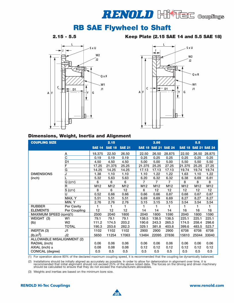
RB SAE Flywheel to Shaft2.15 - 5.5 Keep Plate (2.15 SAE 14 and 5.5 SAE 18)
Dimensions, Weight, Inertia and AlignmentCOUPLING SIZE 2.15 3.86 5.5
SAE 14 SAE 18 SAE 21 SAE 18 SAE 21 SAE 24 SAE 18 SAE 21 SAE 24
A 18.375 22.50 26.50 22.50 26.50 28.875 22.50 26.50 28.875 C 0.19 0.19 0.19 0.25 0.25 0.25 0.25 0.25 0.25 D1 4.50 4.50 4.50 5.00 5.00 5.00 5.50 5.50 5.50 F 17.25 21.375 25.25 21.375 25.25 27.25 21.375 25.25 27.25 G 14.25 14.25 14.25 17.13 17.13 17.13 19.74 19.74 19.74 DIMENSIONS J 1.38 1.10 1.10 1.10 1.22 1.22 1.63 1.10 1.22
(inch) L 5.32 5.63 5.63 6.20 6.32 6.32 6.38 6.69 6.81Q (QTY) 6 6 6 7 7 7 8 8 8R M12 M12 M12 M12 M12 M12 M12 M12 M12
S (QTY) 8 6 12 6 12 12 12 12 12U 0.52 0.66 0.66 0.66 0.66 0.87 0.68 0.67 0.87
MAX. Y 5.51 5.51 5.51 6.69 6.69 6.69 8.27 8.27 8.27MIN. Y 2.76 2.76 2.76 3.15 3.15 3.15 3.54 3.54 3.54
RUBBER Per Cavity 1 1 1 1 1 1 1 1 1ELEMENTS Per Coupling 12 12 12 14 14 14 16 16 16MAXIMUM SPEED (rpm)(1) 2500 2040 1800 2040 1800 1590 2040 1800 1590WEIGHT (3) W1 79.1 79.1 79.1 138.5 138.5 138.5 225.1 225.1 225.1(lb) W2 111.2 174.5 203.2 190.6 243.3 265.3 174.5 258.4 298.6
TOTAL 190.3 253.6 282.3 329.1 381.8 403.8 399.6 483.5 523.7INERTIA (3) J1 1102 1102 1102 2900 2900 2900 6708 6708 6708(lb.in2) J2 5650 11254 17063 13484 22095 27836 15610 25044 33040
ALLOWABLE MISALIGNMENT (2)RADIAL (inch) 0.06 0.06 0.06 0.06 0.06 0.06 0.06 0.06 0.06AXIAL (inch) ± 0.08 0.08 0.08 0.12 0.12 0.12 0.12 0.12 0.12CONICAL (degree) 0.5 0.5 0.5 0.5 0.5 0.5 0.5 0.5 0.5
(1) For operation above 80% of the declared maximum coupling speed, it is recommended that the coupling be dynamically balanced.
(2) Installations should be initially aligned as accurately as possible. In order to allow for deterioration in alignment over time, it is recommended that initial alignment should not exceed 25% of the above noted data. The forces on the driving and driven machinery should be calculated to ensure that they do not exceed the manufacturers allowables.
(3) Weights and inertias are based on the minimum bore size.
36
RENOLD Hi-Tec Couplings www.renold.com
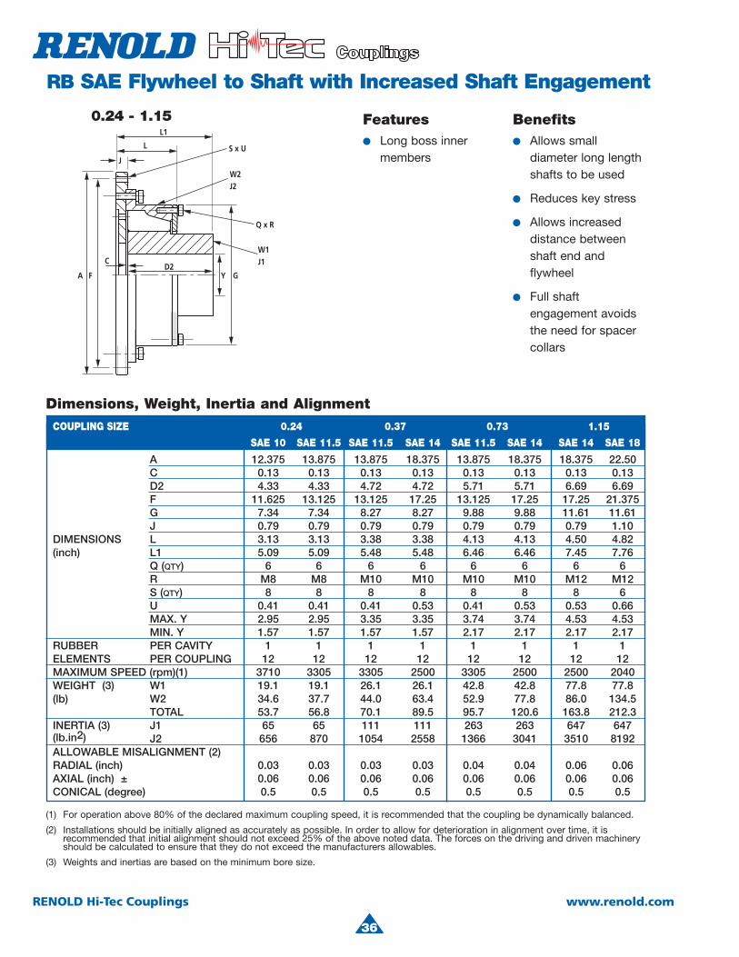
RB SAE Flywheel to Shaft with Increased Shaft Engagement
Features● Long boss inner
members
Benefits● Allows small
diameter long lengthshafts to be used
● Reduces key stress
● Allows increased distance betweenshaft end andflywheel
● Full shaftengagement avoids the need for spacercollars
J
Q x R
L
L1
S x U
W2J2
W1J1
Y G
CD2
FA
0.24 - 1.15
COUPLING SIZE 0.24 0.37 0.73 1.15
SAE 10 SAE 11.5 SAE 11.5 SAE 14 SAE 11.5 SAE 14 SAE 14 SAE 18
A 12.375 13.875 13.875 18.375 13.875 18.375 18.375 22.50 C 0.13 0.13 0.13 0.13 0.13 0.13 0.13 0.13
D2 4.33 4.33 4.72 4.72 5.71 5.71 6.69 6.69F 11.625 13.125 13.125 17.25 13.125 17.25 17.25 21.375G 7.34 7.34 8.27 8.27 9.88 9.88 11.61 11.61
J 0.79 0.79 0.79 0.79 0.79 0.79 0.79 1.10DIMENSIONS L 3.13 3.13 3.38 3.38 4.13 4.13 4.50 4.82
(inch) L1 5.09 5.09 5.48 5.48 6.46 6.46 7.45 7.76Q (QTY) 6 6 6 6 6 6 6 6R M8 M8 M10 M10 M10 M10 M12 M12S (QTY) 8 8 8 8 8 8 8 6U 0.41 0.41 0.41 0.53 0.41 0.53 0.53 0.66MAX. Y 2.95 2.95 3.35 3.35 3.74 3.74 4.53 4.53MIN. Y 1.57 1.57 1.57 1.57 2.17 2.17 2.17 2.17
RUBBER PER CAVITY 1 1 1 1 1 1 1 1ELEMENTS PER COUPLING 12 12 12 12 12 12 12 12MAXIMUM SPEED (rpm)(1) 3710 3305 3305 2500 3305 2500 2500 2040WEIGHT (3) W1 19.1 19.1 26.1 26.1 42.8 42.8 77.8 77.8(lb) W2 34.6 37.7 44.0 63.4 52.9 77.8 86.0 134.5
TOTAL 53.7 56.8 70.1 89.5 95.7 120.6 163.8 212.3INERTIA (3) J1 65 65 111 111 263 263 647 647(lb.in2) J2 656 870 1054 2558 1366 3041 3510 8192ALLOWABLE MISALIGNMENT (2)RADIAL (inch) 0.03 0.03 0.03 0.03 0.04 0.04 0.06 0.06AXIAL (inch) ± 0.06 0.06 0.06 0.06 0.06 0.06 0.06 0.06CONICAL (degree) 0.5 0.5 0.5 0.5 0.5 0.5 0.5 0.5
Dimensions, Weight, Inertia and Alignment
(1) For operation above 80% of the declared maximum coupling speed, it is recommended that the coupling be dynamically balanced.
(2) Installations should be initially aligned as accurately as possible. In order to allow for deterioration in alignment over time, it is recommended that initial alignment should not exceed 25% of the above noted data. The forces on the driving and driven machinery should be calculated to ensure that they do not exceed the manufacturers allowables.
(3) Weights and inertias are based on the minimum bore size.
4
37
RENOLD Hi-Tec Couplings www.renold.com
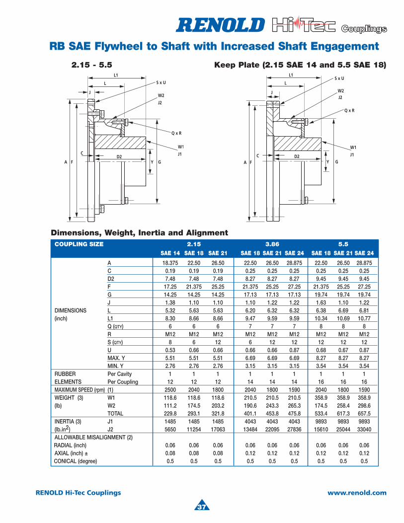
RB SAE Flywheel to Shaft with Increased Shaft Engagement
2.15 - 5.5
COUPLING SIZE 2.15 3.86 5.5
SAE 14 SAE 18 SAE 21 SAE 18 SAE 21 SAE 24 SAE 18 SAE 21 SAE 24
A 18.375 22.50 26.50 22.50 26.50 28.875 22.50 26.50 28.875 C 0.19 0.19 0.19 0.25 0.25 0.25 0.25 0.25 0.25 D2 7.48 7.48 7.48 8.27 8.27 8.27 9.45 9.45 9.45 F 17.25 21.375 25.25 21.375 25.25 27.25 21.375 25.25 27.25 G 14.25 14.25 14.25 17.13 17.13 17.13 19.74 19.74 19.74 J 1.38 1.10 1.10 1.10 1.22 1.22 1.63 1.10 1.22 DIMENSIONS L 5.32 5.63 5.63 6.20 6.32 6.32 6.38 6.69 6.81 (inch) L1 8.30 8.66 8.66 9.47 9.59 9.59 10.34 10.69 10.77 Q (QTY) 6 6 6 7 7 7 8 8 8
R M12 M12 M12 M12 M12 M12 M12 M12 M12S (QTY) 8 6 12 6 12 12 12 12 12U 0.53 0.66 0.66 0.66 0.66 0.87 0.68 0.67 0.87
MAX. Y 5.51 5.51 5.51 6.69 6.69 6.69 8.27 8.27 8.27MIN. Y 2.76 2.76 2.76 3.15 3.15 3.15 3.54 3.54 3.54
RUBBER Per Cavity 1 1 1 1 1 1 1 1 1ELEMENTS Per Coupling 12 12 12 14 14 14 16 16 16MAXIMUM SPEED (rpm) (1) 2500 2040 1800 2040 1800 1590 2040 1800 1590WEIGHT (3) W1 118.6 118.6 118.6 210.5 210.5 210.5 358.9 358.9 358.9(lb) W2 111.2 174.5 203.2 190.6 243.3 265.3 174.5 258.4 298.6
TOTAL 229.8 293.1 321.8 401.1 453.8 475.8 533.4 617.3 657.5INERTIA (3) J1 1485 1485 1485 4043 4043 4043 9893 9893 9893(lb.in2) J2 5650 11254 17063 13484 22095 27836 15610 25044 33040ALLOWABLE MISALIGNMENT (2)RADIAL (inch) 0.06 0.06 0.06 0.06 0.06 0.06 0.06 0.06 0.06AXIAL (inch) ± 0.08 0.08 0.08 0.12 0.12 0.12 0.12 0.12 0.12CONICAL (degree) 0.5 0.5 0.5 0.5 0.5 0.5 0.5 0.5 0.5
Dimensions, Weight, Inertia and Alignment
Keep Plate (2.15 SAE 14 and 5.5 SAE 18)
38
RENOLD Hi-Tec Couplings www.renold.com
RB Technical Data
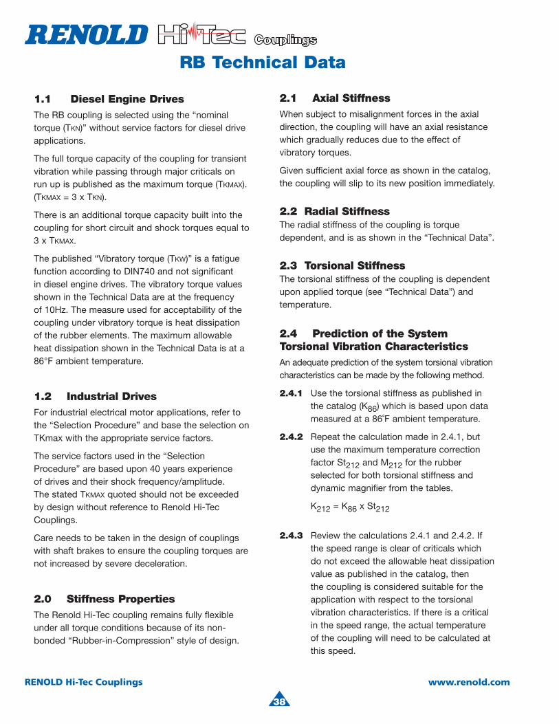
2.1 Axial StiffnessWhen subject to misalignment forces in the axial direction, the coupling will have an axial resistance which gradually reduces due to the effect of vibratory torques.
Given sufficient axial force as shown in the catalog,the coupling will slip to its new position immediately.
2.2 Radial StiffnessThe radial stiffness of the coupling is torque dependent, and is as shown in the “Technical Data”.
2.3 Torsional StiffnessThe torsional stiffness of the coupling is dependent upon applied torque (see “Technical Data”) and temperature.
2.4 Prediction of the System Torsional Vibration CharacteristicsAn adequate prediction of the system torsional vibration characteristics can be made by the following method.
2.4.1 Use the torsional stiffness as published in the catalog (K86) which is based upon data measured at a 86˚F ambient temperature.
2.4.2 Repeat the calculation made in 2.4.1, but use the maximum temperature correction factor St212 and M212 for the rubber selected for both torsional stiffness and dynamic magnifier from the tables.
K212 = K86 x St212
2.4.3 Review the calculations 2.4.1 and 2.4.2. Ifthe speed range is clear of criticals which do not exceed the allowable heat dissipation value as published in the catalog, thenthe coupling is considered suitable for the application with respect to the torsional vibration characteristics. If there is a critical in the speed range, the actual temperature of the coupling will need to be calculated at this speed.
1.1 Diesel Engine DrivesThe RB coupling is selected using the “nominal torque (TKN)” without service factors for diesel drive applications.
The full torque capacity of the coupling for transient vibration while passing through major criticals on run up is published as the maximum torque (TKMAX).(TKMAX = 3 x TKN).
There is an additional torque capacity built into the coupling for short circuit and shock torques equal to 3 x TKMAX.
The published “Vibratory torque (TKW)” is a fatiguefunction according to DIN740 and not significant in diesel engine drives. The vibratory torque values shown in the Technical Data are at the frequency of 10Hz. The measure used for acceptability of the coupling under vibratory torque is heat dissipation of the rubber elements. The maximum allowable heat dissipation shown in the Technical Data is at a 86°F ambient temperature.
1.2 Industrial DrivesFor industrial electrical motor applications, refer to the “Selection Procedure” and base the selection onTKmax with the appropriate service factors.
The service factors used in the “Selection Procedure” are based upon 40 years experience of drives and their shock frequency/amplitude. The stated TKMAX quoted should not be exceeded by design without reference to Renold Hi-Tec Couplings.
Care needs to be taken in the design of couplingswith shaft brakes to ensure the coupling torques are not increased by severe deceleration.
2.0 Stiffness PropertiesThe Renold Hi-Tec coupling remains fully flexible under all torque conditions because of its non-bonded “Rubber-in-Compression” style of design.

4
39
RENOLD Hi-Tec Couplings www.renold.com
SM 70 is considered “standard”
2.6 Temperature Correction FactorKT = K86 x St
2.7 Dynamic Magnifier Correction FactorThe dynamic magnifier of the rubber is subject to temperature variation in the same way as the torsional stiffness.
2.5 Prediction of the ActualCoupling Temperature and
Torsional Stiffness2.5.1 Use the torsional stiffness as published in
the catalog (K86), which is based upon datameasured at 86˚F and the dynamic magnifier(M86) at 86˚F.
2.5.2 Compare the synthesis value of thecalculated heat load in the coupling (PK) at the speed of interest to the “Allowable Heat Dissipation (PKW).”
The coupling temperature rise = ∆F∆F = Tempcoup = x 126
The coupling temperature = ϑϑ = Tempcoup + Ambient Temp.
2.5.3 Calculate the temperature correction factor (St) from 2.6 (if the coupling temperature > 212ºF, then use St212). Calculate the dynamicmagnifier as per 2.7. Repeat the calculationwith the new value of coupling stiffness (KT)and dynamic magnifier (MT).
2.5.4 Calculate the coupling temperature as per 2.5. Repeat calculation until the couplingtemperature agrees with the correction factors for torsional stiffness and dynamic magnifier used in the calculation.
RB Technical Data
PK
PKW( )
MT = M86St
ϕT = ϕ86 x St
RubberGrade
SM 60SM 70SM 80
Tempmax
212212212
St
St212 = 0.75St212 = 0.63St212 = 0.58
SM 70 is considered “standard”
SM 70 is considered “standard”
RubberGrade
SM 60SM 70SM 80
DynamicMagnifierat 86ºF(M86)
864
DynamicMagnifierat 212ºF(M212)
10.79.56.9
RubberGrade
SM 60SM 70SM 80
DynamicMagnifier
(M86)
864
RelativeDamping
ϕ86
0.781.051.57
Rubber Temperature (ϑ) ˚F
40
RENOLD Hi-Tec Couplings www.renold.com
RB Technical Data
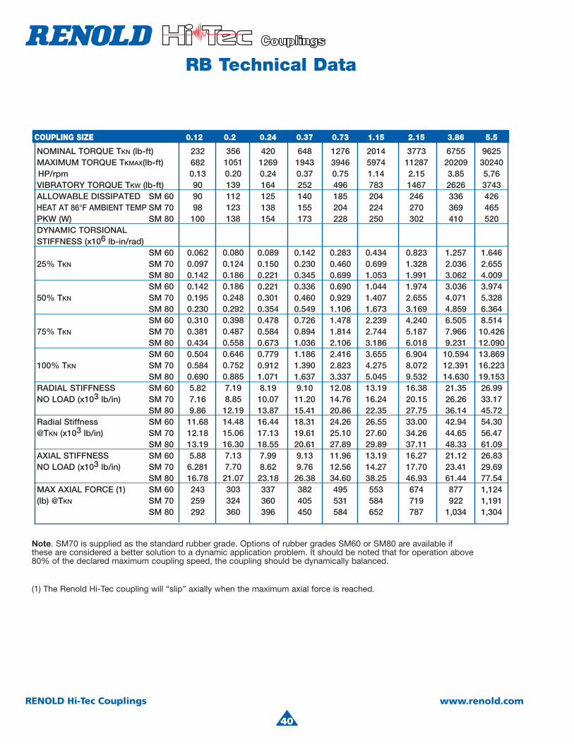
Note. SM70 is supplied as the standard rubber grade. Options of rubber grades SM60 or SM80 are available if these are considered a better solution to a dynamic application problem. It should be noted that for operation above 80% of the declared maximum coupling speed, the coupling should be dynamically balanced.
(1) The Renold Hi-Tec coupling will “slip” axially when the maximum axial force is reached.
COUPLING SIZE 0.12 0.2 0.24 0.37 0.73 1.15 2.15 3.86 5.5
NOMINAL TORQUE TKN (lb-ft) 232 420 648 1276 2014 3773 6755 9625 MAXIMUM TORQUE TKMAX(lb-ft) 682 1269 1943 3946 5974 11287 20209 30240 HP/rpm 0.13 0.24 0.37 0.75 1.14 2.15 3.85 5.76 VIBRATORY TORQUE TKW (lb-ft) 90 164 252 496 783 1467 2626 3743 ALLOWABLE DISSIPATED SM 60 90 125 140 185 204 246 336 426 HEAT AT 86°F AMBIENT TEMP SM 70 98 138 155 204 224 270 369 465 PKW (W) SM 80 100 154 173 228 250 302 410 520 DYNAMIC TORSIONAL STIFFNESS (x106 lb-in/rad)
SM 60 0.062 0.089 0.142 0.283 0.434 0.823 1.257 1.646 25% TKN SM 70 0.097 0.150 0.230 0.460 0.699 1.328 2.036 2.655 SM 80 0.142 0.221 0.345 0.699 1.053 1.991 3.062 4.009 SM 60 0.142 0.221 0.336 0.690 1.044 1.974 3.036 3.974 50% TKN SM 70 0.195 0.301 0.460 0.929 1.407 2.655 4.071 5.328 SM 80 0.230 0.354 0.549 1.106 1.673 3.169 4.859 6.364 SM 60 0.310 0.478 0.726 1.478 2.239 4.240 6.505 8.514 75% TKN SM 70 0.381 0.584 0.894 1.814 2.744 5.187 7.966 10.426 SM 80 0.434 0.673 1.036 2.106 3.186 6.018 9.231 12.090 SM 60 0.504 0.779 1.186 2.416 3.655 6.904 10.594 13.869 100% TKN SM 70 0.584 0.912 1.390 2.823 4.275 8.072 12.391 16.223 SM 80 0.690 1.071 1.637 3.337 5.045 9.532 14.630 19.153 RADIAL STIFFNESS SM 60 5.82 8.19 9.10 12.08 13.19 16.38 21.35 26.99 NO LOAD (x103 lb/in) SM 70 7.16 10.07 11.20 14.76 16.24 20.15 26.26 33.17
SM 80 9.86 13.87 15.41 20.86 22.35 27.75 36.14 45.72 Radial Stiffness SM 60 11.68 16.44 18.31 24.26 26.55 33.00 42.94 54.30 @TKN (x103 lb/in) SM 70 12.18 17.13 19.61 25.10 27.60 34.26 44.65 56.47 SM 80 13.19 18.55 20.61 27.89 29.89 37.11 48.33 61.09 AXIAL STIFFNESS SM 60 5.88 7.99 9.13 11.96 13.19 16.27 21.12 26.83 NO LOAD (x103 lb/in) SM 70 6.281 8.62 9.76 12.56 14.27 17.70 23.41 29.69 SM 80 16.78 23.18 26.38 34.60 38.25 46.93 61.44 77.54 MAX AXIAL FORCE (1) SM 60 243 337 382 495 553 674 877 1,124(lb) @TKN SM 70 259 360 405 531 584 719 922 1,191
SM 80 292 396 450 584 652 787 1,034 1,304
35610510.20139112123138
0.0800.1240.1860.1860.2480.2920.3980.4870.5580.6460.7520.8857.198.85
12.1914.4815.0616.307.137.70
21.07303324360
Note. SM70 is supplied as the standard rubber grade. Options of rubber grades SM60 or SM80 are available if these are considered a better solution to a dynamic application problem. It should be noted that for operation above 80% of the declared maximum coupling speed, the coupling should be dynamically balanced.
(1) The Renold Hi-Tec coupling will “slip” axially when the maximum axial force is reached.
COUPLING SIZE 0.12 0.2 0.24 0.37 0.73 1.15 2.15 3.86 5.5
NOMINAL TORQUE TKN (lb-ft) 232 420 648 1276 2014 3773 6755 9625 MAXIMUM TORQUE TKMAX(lb-ft) 682 1269 1943 3946 5974 11287 20209 30240 HP/rpm 0.13 0.24 0.37 0.75 1.14 2.15 3.85 5.76 VIBRATORY TORQUE TKW (lb-ft) 90 164 252 496 783 1467 2626 3743 ALLOWABLE DISSIPATED SM 60 90 125 140 185 204 246 336 426 HEAT AT 86°F AMBIENT TEMP SM 70 98 138 155 204 224 270 369 465PKW (W) SM 80 100 154 173 228 250 302 410 520
DYNAMIC TORSIONAL STIFFNESS (x106 lb-in/rad)
SM 60 0.062 0.089 0.142 0.283 0.434 0.823 1.257 1.646 25% TKN SM 70 0.097 0.150 0.230 0.460 0.699 1.328 2.036 2.655 SM 80 0.142 0.221 0.345 0.699 1.053 1.991 3.062 4.009 SM 60 0.142 0.221 0.336 0.690 1.044 1.974 3.036 3.974 50% TKN SM 70 0.195 0.301 0.460 0.929 1.407 2.655 4.071 5.328 SM 80 0.230 0.354 0.549 1.106 1.673 3.169 4.859 6.364 SM 60 0.310 0.478 0.726 1.478 2.239 4.240 6.505 8.514 75% TKN SM 70 0.381 0.584 0.894 1.814 2.744 5.187 7.966 10.426 SM 80 0.434 0.673 1.036 2.106 3.186 6.018 9.231 12.090 SM 60 0.504 0.779 1.186 2.416 3.655 6.904 10.594 13.869 100% TKN SM 70 0.584 0.912 1.390 2.823 4.275 8.072 12.391 16.223 SM 80 0.690 1.071 1.637 3.337 5.045 9.532 14.630 19.153 RADIAL STIFFNESS SM 60 5.82 8.19 9.10 12.08 13.19 16.38 21.35 26.99NO LOAD (x103 lb/in) SM 70 7.16 10.07 11.20 14.76 16.24 20.15 26.26 33.17
SM 80 9.86 13.87 15.41 20.86 22.35 27.75 36.14 45.72Radial Stiffness SM 60 11.68 16.44 18.31 24.26 26.55 33.00 42.94 54.30
@TKN (x103 lb/in) SM 70 12.18 17.13 19.61 25.10 27.60 34.26 44.65 56.47 SM 80 13.19 18.55 20.61 27.89 29.89 37.11 48.33 61.09AXIAL STIFFNESS SM 60 5.88 7.99 9.13 11.96 13.19 16.27 21.12 26.83
NO LOAD (x103 lb/in) SM 70 6.281 8.62 9.76 12.56 14.27 17.70 23.41 29.69 SM 80 16.78 23.18 26.38 34.60 38.25 46.93 61.44 77.54MAX AXIAL FORCE (1) SM 60 243 337 382 495 553 674 877 1,124
(lb) @TKN SM 70 259 360 405 531 584 719 922 1,191 SM 80 292 396 450 584 652 787 1,034 1,304
35610510.20139112123138
0.0800.1240.1860.1860.2480.2920.3980.4870.5580.6460.7520.8857.198.8512.1914.4815.0616.307.137.7021.07303324360
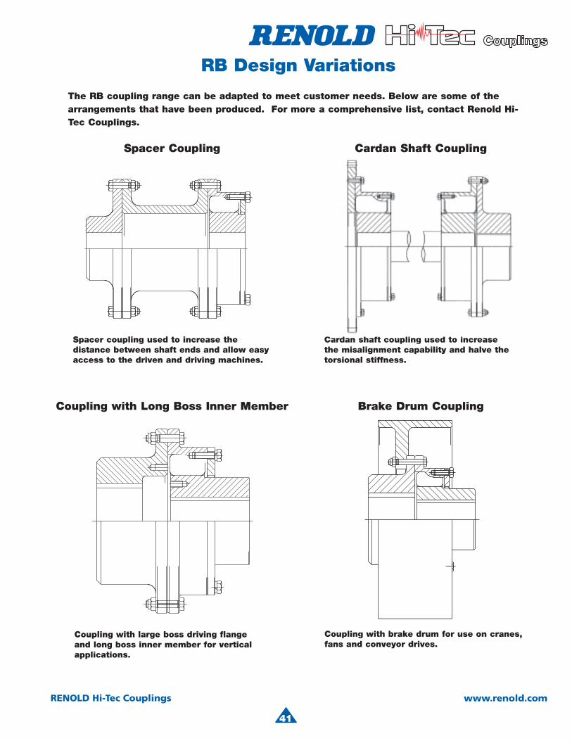
4
41
RENOLD Hi-Tec Couplings www.renold.com
RB Design Variations
Coupling with large boss driving flangeand long boss inner member for verticalapplications.
Cardan shaft coupling used to increase the misalignment capability and halve the torsional stiffness.
Spacer coupling used to increase the distance between shaft ends and allow easy access to the driven and driving machines.
Coupling with brake drum for use on cranes, fans and conveyor drives.
The RB coupling range can be adapted to meet customer needs. Below are some of the arrangements that have been produced. For more a comprehensive list, contact Renold Hi-Tec Couplings.
Spacer Coupling
Coupling with Long Boss Inner Member
Cardan Shaft Coupling
Brake Drum Coupling
RENOLD Hi-Tec Couplings www.renold.com
42
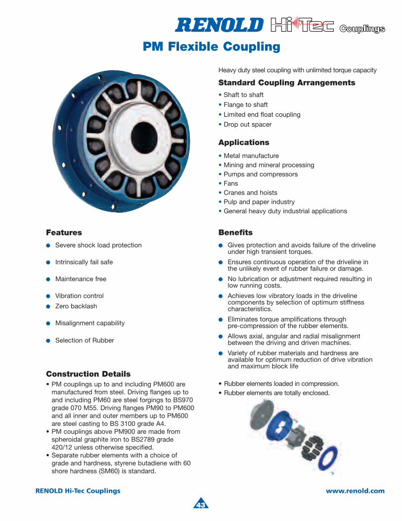
4
43
RENOLD Hi-Tec Couplings www.renold.com
PM Flexible Coupling
Heavy duty steel coupling with unlimited torque capacity
Standard Coupling Arrangements
•• Shaft to shaft
• Flange to shaft
• Limited end float coupling
• Drop out spacer
Applications
• Metal manufacture• Mining and mineral processing• Pumps and compressors• Fans• Cranes and hoists• Pulp and paper industry• General heavy duty industrial applications
Features
● Severe shock load protection
● Intrinsically fail safe
●● Maintenance free
●● Vibration control
●● Zero backlash
●● Misalignment capability
●● Selection of Rubber
Construction Details• PM couplings up to and including PM600 are
manufactured from steel. Driving flanges up toand including PM60 are steel forgings to BS970 grade 070 M55. Driving flanges PM90 to PM600and all inner and outer members up to PM600are steel casting to BS 3100 grade A4.
• PM couplings above PM900 are made from spheroidal graphite iron to BS2789 grade 420/12 unless otherwise specified.
• Separate rubber elements with a choice ofgrade and hardness, styrene butadiene with 60 shore hardness (SM60) is standard.
Benefits
●● Gives protection and avoids failure of the driveline under high transient torques.
●● Ensures continuous operation of the driveline in the unlikely event of rubber failure or damage.
●● No lubrication or adjustment required resulting in low running costs.
●● Achieves low vibratory loads in the driveline components by selection of optimum stiffness characteristics.
●● Eliminates torque amplifications throughpre-compression of the rubber elements.
●● Allows axial, angular and radial misalignment between the driving and driven machines.
●● Variety of rubber materials and hardness are available for optimum reduction of drive vibration and maximum block life
• Rubber elements loaded in compression.• Rubber elements are totally enclosed.
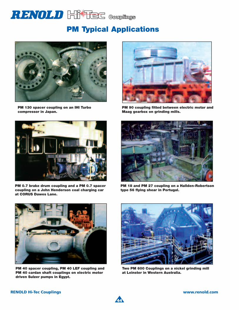
44
RENOLD Hi-Tec Couplings www.renold.com
PM Typical Applications
Two PM 600 Couplings on a nickel grinding mill at Leinster in Western Australia.
PM 40 spacer coupling, PM 40 LEF coupling andPM 40 cardan shaft couplings on electric motor driven Sulzer pumps in Egypt.
PM 0.7 brake drum coupling and a PM 0.7 spacercoupling on a John Henderson coal charging carat CORUS Dawes Lane.
PM 18 and PM 27 coupling on a Hallden-Robertson type 56 flying shear in Portugal.
PM 130 spacer coupling on an IHI Turbocompressor in Japan.
PM 90 coupling fitted between electric motor andMaag gearbox on grinding mills.
44
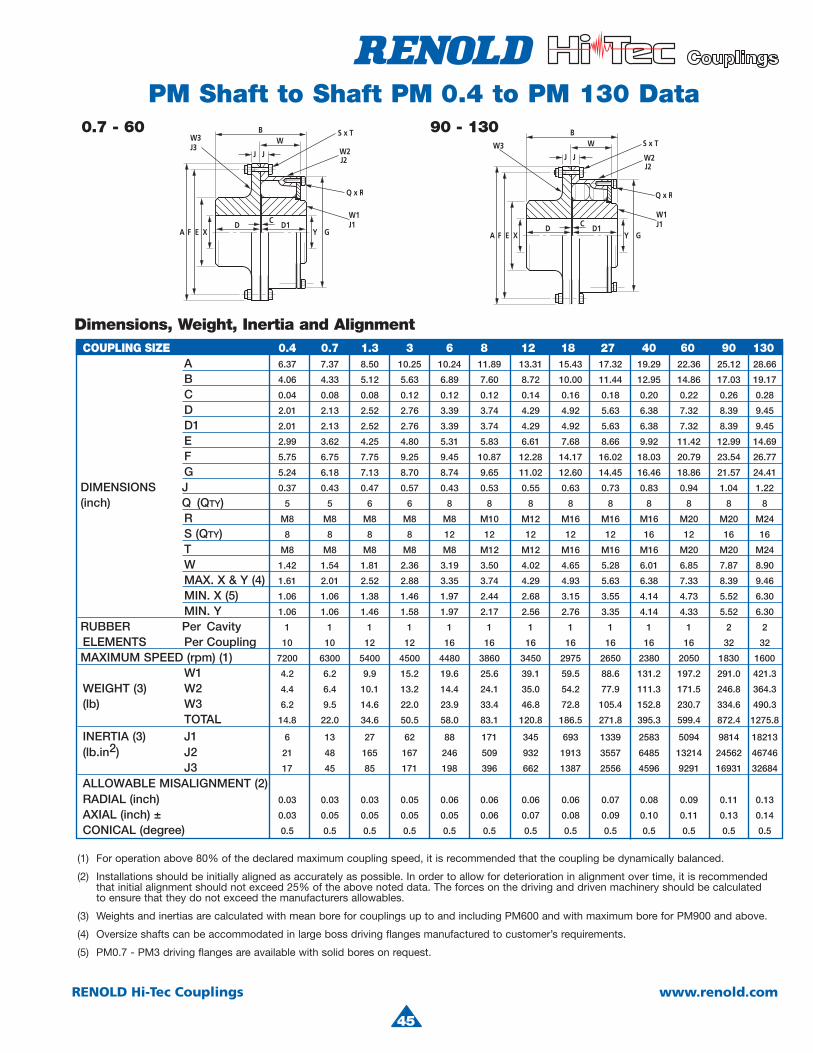
4
45
RENOLD Hi-Tec Couplings www.renold.com
COUPLING SIZE 0.4 0.7 1.3 3 6 8 12 18 27 40 60 90 130A 6.37 7.37 8.50 10.25 10.24 11.89 13.31 15.43 17.32 19.29 22.36 25.12 28.66
B 4.06 4.33 5.12 5.63 6.89 7.60 8.72 10.00 11.44 12.95 14.86 17.03 19.17
C 0.04 0.08 0.08 0.12 0.12 0.12 0.14 0.16 0.18 0.20 0.22 0.26 0.28
D 2.01 2.13 2.52 2.76 3.39 3.74 4.29 4.92 5.63 6.38 7.32 8.39 9.45
D1 2.01 2.13 2.52 2.76 3.39 3.74 4.29 4.92 5.63 6.38 7.32 8.39 9.45
E 2.99 3.62 4.25 4.80 5.31 5.83 6.61 7.68 8.66 9.92 11.42 12.99 14.69
F 5.75 6.75 7.75 9.25 9.45 10.87 12.28 14.17 16.02 18.03 20.79 23.54 26.77
G 5.24 6.18 7.13 8.70 8.74 9.65 11.02 12.60 14.45 16.46 18.86 21.57 24.41
DIMENSIONS J 0.37 0.43 0.47 0.57 0.43 0.53 0.55 0.63 0.73 0.83 0.94 1.04 1.22
(inch) Q (QTY) 5 5 6 6 8 8 8 8 8 8 8 8 8
R M8 M8 M8 M8 M8 M10 M12 M16 M16 M16 M20 M20 M24
S (QTY) 8 8 8 8 12 12 12 12 12 16 12 16 16
T M8 M8 M8 M8 M8 M12 M12 M16 M16 M16 M20 M20 M24
W 1.42 1.54 1.81 2.36 3.19 3.50 4.02 4.65 5.28 6.01 6.85 7.87 8.90
MAX. X & Y (4) 1.61 2.01 2.52 2.88 3.35 3.74 4.29 4.93 5.63 6.38 7.33 8.39 9.46
MIN. X (5) 1.06 1.06 1.38 1.46 1.97 2.44 2.68 3.15 3.55 4.14 4.73 5.52 6.30
MIN. Y 1.06 1.06 1.46 1.58 1.97 2.17 2.56 2.76 3.35 4.14 4.33 5.52 6.30
RUBBER Per Cavity 1 1 1 1 1 1 1 1 1 1 1 2 2
ELEMENTS Per Coupling 10 10 12 12 16 16 16 16 16 16 16 32 32
MAXIMUM SPEED (rpm) (1) 7200 6300 5400 4500 4480 3860 3450 2975 2650 2380 2050 1830 1600
W1 4.2 6.2 9.9 15.2 19.6 25.6 39.1 59.5 88.6 131.2 197.2 291.0 421.3
WEIGHT (3) W2 4.4 6.4 10.1 13.2 14.4 24.1 35.0 54.2 77.9 111.3 171.5 246.8 364.3
(lb) W3 6.2 9.5 14.6 22.0 23.9 33.4 46.8 72.8 105.4 152.8 230.7 334.6 490.3
TOTAL 14.8 22.0 34.6 50.5 58.0 83.1 120.8 186.5 271.8 395.3 599.4 872.4 1275.8
INERTIA (3) J1 6 13 27 62 88 171 345 693 1339 2583 5094 9814 18213
(lb.in2) J2 21 48 165 167 246 509 932 1913 3557 6485 13214 24562 46746
J3 17 45 85 171 198 396 662 1387 2556 4596 9291 16931 32684
ALLOWABLE MISALIGNMENT (2)RADIAL (inch) 0.03 0.03 0.03 0.05 0.06 0.06 0.06 0.06 0.07 0.08 0.09 0.11 0.13
AXIAL (inch) ± 0.03 0.05 0.05 0.05 0.05 0.06 0.07 0.08 0.09 0.10 0.11 0.13 0.14
CONICAL (degree) 0.5 0.5 0.5 0.5 0.5 0.5 0.5 0.5 0.5 0.5 0.5 0.5 0.5
PM Shaft to Shaft PM 0.4 to PM 130 Data0.7 - 60
(1) For operation above 80% of the declared maximum coupling speed, it is recommended that the coupling be dynamically balanced.
(2) Installations should be initially aligned as accurately as possible. In order to allow for deterioration in alignment over time, it is recommended that initial alignment should not exceed 25% of the above noted data. The forces on the driving and driven machinery should be calculated to ensure that they do not exceed the manufacturers allowables.
(3) Weights and inertias are calculated with mean bore for couplings up to and including PM600 and with maximum bore for PM900 and above.
(4) Oversize shafts can be accommodated in large boss driving flanges manufactured to customer’s requirements.
(5) PM0.7 - PM3 driving flanges are available with solid bores on request.
Dimensions, Weight, Inertia and Alignment
90 - 130
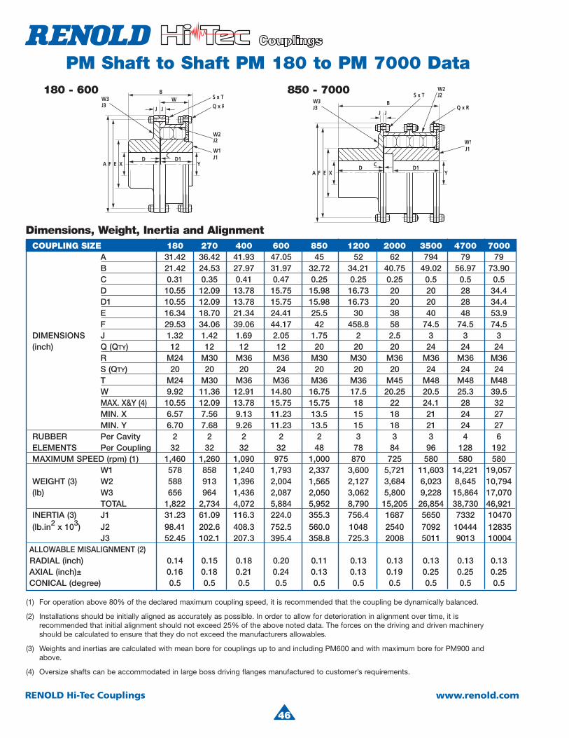
46
RENOLD Hi-Tec Couplings www.renold.com
PM Shaft to Shaft PM 180 to PM 7000 Data180 - 600
(1) For operation above 80% of the declared maximum coupling speed, it is recommended that the coupling be dynamically balanced.
(2) Installations should be initially aligned as accurately as possible. In order to allow for deterioration in alignment over time, it is recommended that initial alignment should not exceed 25% of the above noted data. The forces on the driving and driven machinery should be calculated to ensure that they do not exceed the manufacturers allowables.
(3) Weights and inertias are calculated with mean bore for couplings up to and including PM600 and with maximum bore for PM900 and above.
(4) Oversize shafts can be accommodated in large boss driving flanges manufactured to customer’s requirements.
Dimensions, Weight, Inertia and AlignmentCOUPLING SIZE 180 270 400 600 850 1200 2000 3500 4700 7000
A 31.42 36.42 41.93 47.05 45 52 62 794 79 79B 21.42 24.53 27.97 31.97 32.72 34.21 40.75 49.02 56.97 73.90
C 0.31 0.35 0.41 0.47 0.25 0.25 0.25 0.5 0.5 0.5 D 10.55 12.09 13.78 15.75 15.98 16.73 20 20 28 34.4 D1 10.55 12.09 13.78 15.75 15.98 16.73 20 20 28 34.4 E 16.34 18.70 21.34 24.41 25.5 30 38 40 48 53.9 F 29.53 34.06 39.06 44.17 42 458.8 58 74.5 74.5 74.5 DIMENSIONS J 1.32 1.42 1.69 2.05 1.75 2 2.5 3 3 3
(inch) Q (QTY) 12 12 12 12 20 20 20 24 24 24R M24 M30 M36 M36 M30 M30 M36 M36 M36 M36
S (QTY) 20 20 20 24 20 20 20 24 24 24T M24 M30 M36 M36 M36 M36 M45 M48 M48 M48
W 9.92 11.36 12.91 14.80 16.75 17.5 20.25 20.5 25.3 39.5 MAX. X&Y (4) 10.55 12.09 13.78 15.75 15.75 18 22 24.1 28 32 MIN. X 6.57 7.56 9.13 11.23 13.5 15 18 21 24 27 MIN. Y 6.70 7.68 9.26 11.23 13.5 15 18 21 24 27 RUBBER Per Cavity 2 2 2 2 2 3 3 3 4 6
ELEMENTS Per Coupling 32 32 32 32 48 78 84 96 128 192MAXIMUM SPEED (rpm) (1) 1,460 1,260 1,090 975 1,000 870 725 580 580 580
W1 578 858 1,240 1,793 2,337 3,600 5,721 11,603 14,221 19,057 WEIGHT (3) W2 588 913 1,396 2,004 1,565 2,127 3,684 6,023 8,645 10,794 (lb) W3 656 964 1,436 2,087 2,050 3,062 5,800 9,228 15,864 17,070 TOTAL 1,822 2,734 4,072 5,884 5,952 8,790 15,205 26,854 38,730 46,921 INERTIA (3) J1 31.23 61.09 116.3 224.0 355.3 756.4 1687 5650 7332 10470 (lb.in2 x 103) J2 98.41 202.6 408.3 752.5 560.0 1048 2540 7092 10444 12835
J3 52.45 102.1 207.3 395.4 358.8 725.3 2008 5011 9013 10004ALLOWABLE MISALIGNMENT (2)RADIAL (inch) 0.14 0.15 0.18 0.20 0.11 0.13 0.13 0.13 0.13 0.13
AXIAL (inch)± 0.16 0.18 0.21 0.24 0.13 0.13 0.19 0.25 0.25 0.25 CONICAL (degree) 0.5 0.5 0.5 0.5 0.5 0.5 0.5 0.5 0.5 0.5
850 - 7000
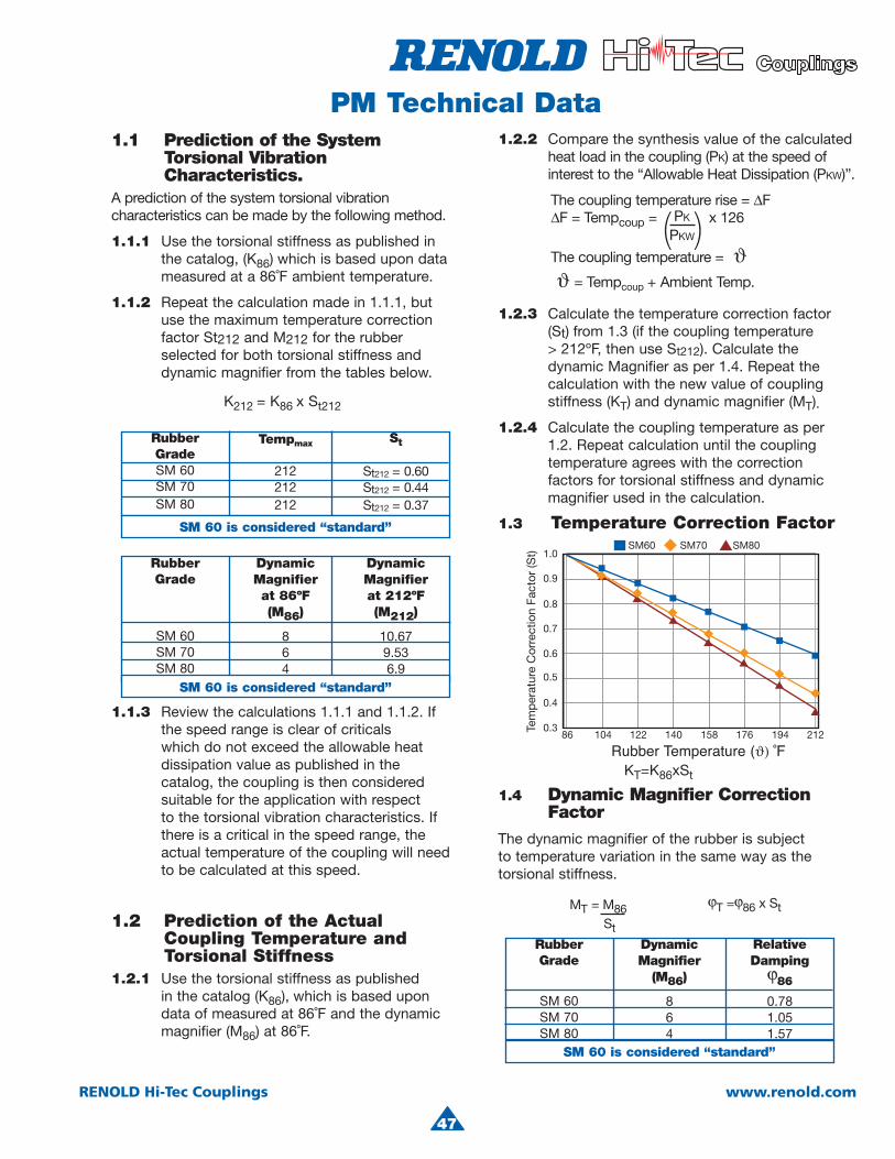
4
47
RENOLD Hi-Tec Couplings www.renold.com
PM Technical Data1.1 Prediction of the System Torsional Vibration Characteristics.A prediction of the system torsional vibration characteristics can be made by the following method.
1.1.1 Use the torsional stiffness as published in the catalog, (K86) which is based upon datameasured at a 86˚F ambient temperature.
1.1.2 Repeat the calculation made in 1.1.1, butuse the maximum temperature correction factor St212 and M212 for the rubber selected for both torsional stiffness and dynamic magnifier from the tables below.
K212 = K86 x St212
1.1.3 Review the calculations 1.1.1 and 1.1.2. Ifthe speed range is clear of criticals which do not exceed the allowable heatdissipation value as published in the catalog, the coupling is then considered suitable for the application with respect to the torsional vibration characteristics. Ifthere is a critical in the speed range, theactual temperature of the coupling will need to be calculated at this speed.
1.2 Prediction of the Actual Coupling Temperature and Torsional Stiffness1.2.1 Use the torsional stiffness as published
in the catalog (K86), which is based upondata of measured at 86˚F and the dynamic magnifier (M86) at 86˚F.
1.2.2 Compare the synthesis value of the calculated heat load in the coupling (PK) at the speed of interest to the “Allowable Heat Dissipation (PKW)”.
The coupling temperature rise = ∆F∆F = Tempcoup = x 126
The coupling temperature = ϑϑ = Tempcoup + Ambient Temp.
1.2.3 Calculate the temperature correction factor (St) from 1.3 (if the coupling temperature > 212ºF, then use St212). Calculate the dynamic Magnifier as per 1.4. Repeat the calculation with the new value of coupling stiffness (KT) and dynamic magnifier (MT).
1.2.4 Calculate the coupling temperature as per 1.2. Repeat calculation until the coupling temperature agrees with the correction factors for torsional stiffness and dynamic magnifier used in the calculation.
1.3 Temperature Correction Factor
1.4 Dynamic Magnifier CorrectionFactor
The dynamic magnifier of the rubber is subject to temperature variation in the same way as the torsional stiffness.
MT = M86St
RubberGrade
SM 60SM 70SM 80
DynamicMagnifier
(M86)
864
RelativeDamping
ϕ86
0.781.051.57
PK
PKW( )
ϕT =ϕ86 x St
RubberGradeSM 60SM 70SM 80
Tempmax
212212212
St
St212 = 0.60St212 = 0.44St212 = 0.37
SM 60 is considered “standard”
RubberGrade
SM 60SM 70SM 80
DynamicMagnifierat 86ºF(M86)
864
DynamicMagnifierat 212ºF(M212)
10.679.536.9
SM 60 is considered “standard”SM 60 is considered “standard”
SM 60 is considered “standard”
KT=K86xSt
Rubber Temperature (ϑ) ˚F
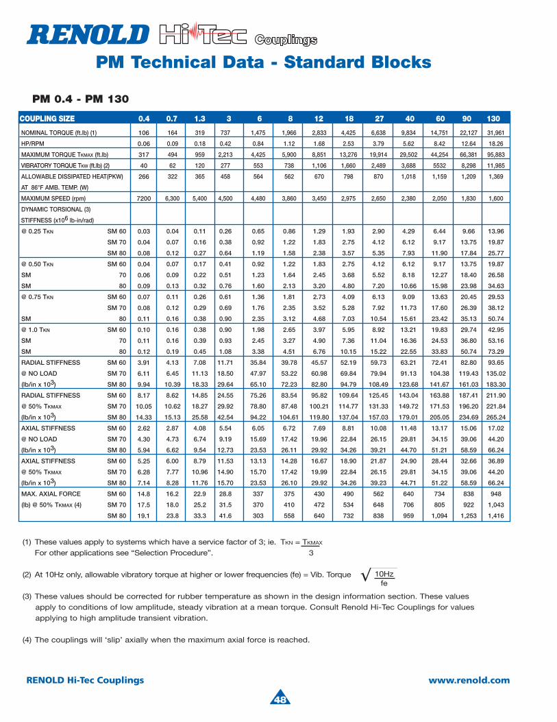
48
RENOLD Hi-Tec Couplings www.renold.com
PM Technical Data - Standard Blocks
PM 0.4 - PM 130
(1) These values apply to systems which have a service factor of 3; ie. For other applications see “Selection Procedure”.
(2) At 10Hz only, allowable vibratory torque at higher or lower frequencies (fe) = Vib. Torque
(3) These values should be corrected for rubber temperature as shown in the design information section. These values apply to conditions of low amplitude, steady vibration at a mean torque. Consult Renold Hi-Tec Couplings for values applying to high amplitude transient vibration.
(4) The couplings will ‘slip’ axially when the maximum axial force is reached.
TKN = TKMAX
3
10Hzfe
106
0.06
317
40
266
7200
0.03
0.04
0.08
0.04
0.06
0.09
0.07
0.08
0.11
0.10
0.11
0.12
3.91
6.11
9.94
8.17
10.05
14.33
2.62
4.30
5.94
5.25
6.28
7.14
14.8
17.5
19.1
COUPLING SIZE 0.4 0.7 1.3 3 6 8 12 18 27 40 60 90 130
NOMINAL TORQUE (ft.lb) (1) 164 319 737 1,475 1,966 2,833 4,425 6,638 9,834 14,751 22,127 31,961
HP/RPM 0. 09 0.18 0.42 0.84 1.12 1.68 2.53 3.79 5.62 8.42 12.64 18.26
MAXIMUM TORQUE TKMAX (ft.lb) 494 959 2,213 4,425 5,900 8,851 13,276 19,914 29,502 44,254 66,381 95,883
VIBRATORY TORQUE TKW (ft.lb) (2) 62 120 277 553 738 1,106 1,660 2,489 3,688 5532 8,298 11,985
ALLOWABLE DISSIPATED HEAT(PKW) 322 365 458 564 562 670 798 870 1,018 1,159 1,209 1,369
AT 86°F AMB. TEMP. (W)
MAXIMUM SPEED (rpm) 6,300 5,400 4,500 4,480 3,860 3,450 2,975 2,650 2,380 2,050 1,830 1,600
DYNAMIC TORSIONAL (3)
STIFFNESS (x106 lb-in/rad)
@ 0.25 TKN SM 60 0.04 0.11 0.26 0.65 0.86 1.29 1.93 2.90 4.29 6.44 9.66 13.96
SM 70 0.07 0.16 0.38 0.92 1.22 1.83 2.75 4.12 6.12 9.17 13.75 19.87
SM 80 0.12 0.27 0.64 1.19 1.58 2.38 3.57 5.35 7.93 11.90 17.84 25.77
@ 0.50 TKN SM 60 0.07 0.17 0.41 0.92 1.22 1.83 2.75 4.12 6.12 9.17 13.75 19.87
SM 70 0.09 0.22 0.51 1.23 1.64 2.45 3.68 5.52 8.18 12.27 18.40 26.58
SM 80 0.13 0.32 0.76 1.60 2.13 3.20 4.80 7.20 10.66 15.98 23.98 34.63
@ 0.75 TKN SM 60 0.11 0.26 0.61 1.36 1.81 2.73 4.09 6.13 9.09 13.63 20.45 29.53
SM 70 0.12 0.29 0.69 1.76 2.35 3.52 5.28 7.92 11.73 17.60 26.39 38.12
SM 80 0.16 0.38 0.90 2.35 3.12 4.68 7.03 10.54 15.61 23.42 35.13 50.74
@ 1.0 TKN SM 60 0.16 0.38 0.90 1.98 2.65 3.97 5.95 8.92 13.21 19.83 29.74 42.95
SM 70 0.16 0.39 0.93 2.45 3.27 4.90 7.36 11.04 16.36 24.53 36.80 53.16
SM 80 0.19 0.45 1.08 3.38 4.51 6.76 10.15 15.22 22.55 33.83 50.74 73.29
RADIAL STIFFNESS SM 60 4.13 7.08 11.71 35.84 39.78 45.57 52.19 59.73 63.21 72.41 82.80 93.65
@ NO LOAD SM 70 6.45 11.13 18.50 47.97 53.22 60.98 69.84 79.94 91.13 104.38 119.43 135.02
(lb/in x 103) SM 80 10.39 18.33 29.64 65.10 72.23 82.80 94.79 108.49 123.68 141.67 161.03 183.30
RADIAL STIFFNESS SM 60 8.62 14.85 24.55 75.26 83.54 95.82 109.64 125.45 143.04 163.88 187.41 211.90
@ 50% TKMAX SM 70 10.62 18.27 29.92 78.80 87.48 100.21 114.77 131.33 149.72 171.53 196.20 221.84
(lb/in x 103) SM 80 15.13 25.58 42.54 94.22 104.61 119.80 137.04 157.03 179.01 205.05 234.69 265.24
AXIAL STIFFNESS SM 60 2.87 4.08 5.54 6.05 6.72 7.69 8.81 10.08 11.48 13.17 15.06 17.02
@ NO LOAD SM 70 4.73 6.74 9.19 15.69 17.42 19.96 22.84 26.15 29.81 34.15 39.06 44.20
(lb/in x 103) SM 80 6.62 9.54 12.73 23.53 26.11 29.92 34.26 39.21 44.70 51.21 58.59 66.24
AXIAL STIFFNESS SM 60 6.00 8.79 11.53 13.13 14.28 16.67 18.90 21.87 24.90 28.44 32.66 36.89
@ 50% TKMAX SM 70 7.77 10.96 14.90 15.70 17.42 19.99 22.84 26.15 29.81 34.15 39.06 44.20
(lb/in x 103) SM 80 8.28 11.76 15.70 23.53 26.10 29.92 34.26 39.23 44.71 51.22 58.59 66.24
MAX. AXIAL FORCE SM 60 16.2 22.9 28.8 337 375 430 490 562 640 734 838 948
(lb) @ 50% TKMAX (4) SM 70 18.0 25.2 31.5 370 410 472 534 648 706 805 922 1,043
SM 80 23.8 33.3 41.6 303 558 640 732 838 959 1,094 1,253 1,416
PM 0.4 - PM 130
(1) These values apply to systems which have a service factor of 3; ie. For other applications see “Selection Procedure”.
(2) At 10Hz only, allowable vibratory torque at higher or lower frequencies (fe) = Vib. Torque
(3) These values should be corrected for rubber temperature as shown in the design information section. These values apply to conditions of low amplitude, steady vibration at a mean torque. Consult Renold Hi-Tec Couplings for values applying to high amplitude transient vibration.
(4) The couplings will ‘slip’ axially when the maximum axial force is reached.
TKN = TKMAX
3
10Hzfe
106
0.06
317
40
266
7200
0.03
0.04
0.08
0.04
0.06
0.09
0.07
0.08
0.11
0.10
0.11
0.12
3.91
6.11
9.94
8.17
10.05
14.33
2.62
4.30
5.94
5.25
6.28
7.14
14.8
17.5
19.1
COUPLING SIZE 0.4 0.7 1.3 3 6 8 12 18 27 40 60 90 130
NOMINAL TORQUE (ft.lb) (1) 164 319 737 1,475 1,966 2,833 4,425 6,638 9,834 14,751 22,127 31,961
HP/RPM 0.09 0.18 0.42 0.84 1.12 1.68 2.53 3.79 5.62 8.42 12.64 18.26
MAXIMUM TORQUE TKMAX (ft.lb) 494 959 2,213 4,425 5,900 8,851 13,276 19,914 29,502 44,254 66,381 95,883
VIBRATORY TORQUE TKW (ft.lb) (2) 62 120 277 553 738 1,106 1,660 2,489 3,688 5532 8,298 11,985
ALLOWABLE DISSIPATED HEAT(PKW) 322 365 458 564 562 670 798 870 1,018 1,159 1,209 1,369
AT 86°F AMB. TEMP. (W)
MAXIMUM SPEED (rpm) 6,300 5,400 4,500 4,480 3,860 3,450 2,975 2,650 2,380 2,050 1,830 1,600
DYNAMIC TORSIONAL (3)
STIFFNESS (x106 lb-in/rad)
@ 0.25 TKN SM 60 0.04 0.11 0.26 0.65 0.86 1.29 1.93 2.90 4.29 6.44 9.66 13.96
SM 70 0.07 0.16 0.38 0.92 1.22 1.83 2.75 4.12 6.12 9.17 13.75 19.87
SM 80 0.12 0.27 0.64 1.19 1.58 2.38 3.57 5.35 7.93 11.90 17.84 25.77
@ 0.50 TKN SM 60 0.07 0.17 0.41 0.92 1.22 1.83 2.75 4.12 6.12 9.17 13.75 19.87
SM 70 0.09 0.22 0.51 1.23 1.64 2.45 3.68 5.52 8.18 12.27 18.40 26.58
SM 80 0.13 0.32 0.76 1.60 2.13 3.20 4.80 7.20 10.66 15.98 23.98 34.63
@ 0.75 TKN SM 60 0.11 0.26 0.61 1.36 1.81 2.73 4.09 6.13 9.09 13.63 20.45 29.53
SM 70 0.12 0.29 0.69 1.76 2.35 3.52 5.28 7.92 11.73 17.60 26.39 38.12
SM 80 0.16 0.38 0.90 2.35 3.12 4.68 7.03 10.54 15.61 23.42 35.13 50.74
@ 1.0 TKN SM 60 0.16 0.38 0.90 1.98 2.65 3.97 5.95 8.92 13.21 19.83 29.74 42.95
SM 70 0.16 0.39 0.93 2.45 3.27 4.90 7.36 11.04 16.36 24.53 36.80 53.16
SM 80 0.19 0.45 1.08 3.38 4.51 6.76 10.15 15.22 22.55 33.83 50.74 73.29
RADIAL STIFFNESS SM 60 4.13 7.08 11.71 35.84 39.78 45.57 52.19 59.73 63.21 72.41 82.80 93.65
@ NO LOAD SM 70 6.45 11.13 18.50 47.97 53.22 60.98 69.84 79.94 91.13 104.38 119.43 135.02
(lb/in x 103) SM 80 10.39 18.33 29.64 65.10 72.23 82.80 94.79 108.49 123.68 141.67 161.03 183.30
RADIAL STIFFNESS SM 60 8.62 14.85 24.55 75.26 83.54 95.82 109.64 125.45 143.04 163.88 187.41 211.90
@ 50% TKMAX SM 70 10.62 18.27 29.92 78.80 87.48 100.21 114.77 131.33 149.72 171.53 196.20 221.84
(lb/in x 103) SM 80 15.13 25.58 42.54 94.22 104.61 119.80 137.04 157.03 179.01 205.05 234.69 265.24
AXIAL STIFFNESS SM 60 2.87 4.08 5.54 6.05 6.72 7.69 8.81 10.08 11.48 13.17 15.06 17.02
@ NO LOAD SM 70 4.73 6.74 9.19 15.69 17.42 19.96 22.84 26.15 29.81 34.15 39.06 44.20
(lb/in x 103) SM 80 6.62 9.54 12.73 23.53 26.11 29.92 34.26 39.21 44.70 51.21 58.59 66.24
AXIAL STIFFNESS SM 60 6.00 8.79 11.53 13.13 14.28 16.67 18.90 21.87 24.90 28.44 32.66 36.89
@ 50% TKMAX SM 70 7.77 10.96 14.90 15.70 17.42 19.99 22.84 26.15 29.81 34.15 39.06 44.20
(lb/in x 103) SM 80 8.28 11.76 15.70 23.53 26.10 29.92 34.26 39.23 44.71 51.22 58.59 66.24
MAX. AXIAL FORCE SM 60 16.2 22.9 28.8 337 375 430 490 562 640 734 838 948
(lb) @ 50% TKMAX (4) SM 70 18.0 25.2 31.5 370 410 472 534 648 706 805 922 1,043
SM 80 23.8 33.3 41.6 303 558 640 732 838 959 1,094 1,253 1,416
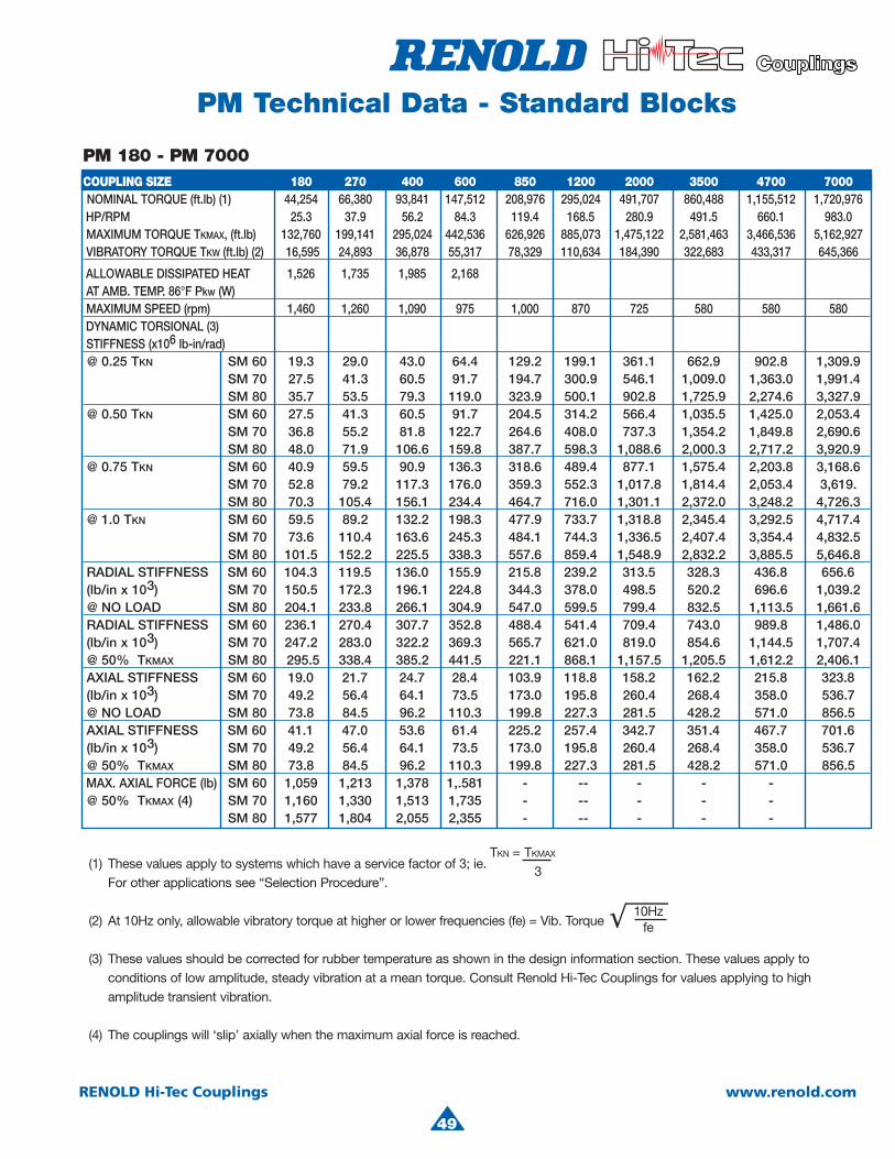
4
(1) These values apply to systems which have a service factor of 3; ie.For other applications see “Selection Procedure”.
(2) At 10Hz only, allowable vibratory torque at higher or lower frequencies (fe) = Vib. Torque
(3) These values should be corrected for rubber temperature as shown in the design information section. These values apply to conditions of low amplitude, steady vibration at a mean torque. Consult Renold Hi-Tec Couplings for values applying to high amplitude transient vibration.
(4) The couplings will ‘slip’ axially when the maximum axial force is reached.
TKN = TKMAX
3
PM 180 - PM 7000COUPLING SIZE 180 270 400 600 850 1200 2000 3500 4700 7000 NOMINAL TORQUE (ft.lb) (1) 44,254 66,380 93,841 147,512 208,976 295,024 491,707 860,488 1,155,512 1,720,976 HP/RPM 25.3 37.9 56.2 84.3 119.4 168.5 280.9 491.5 660.1 983.0 MAXIMUM TORQUE TKMAX, (ft.lb) 132,760 199,141 295,024 442,536 626,926 885,073 1,475,122 2,581,463 3,466,536 5,162,927 VIBRATORY TORQUE TKW (ft.lb) (2) 16,595 24,893 36,878 55,317 78,329 110,634 184,390 322,683 433,317 645,366
ALLOWABLE DISSIPATED HEAT 1,526 1,735 1,985 2,168AT AMB. TEMP. 86°F Pkw (W) MAXIMUM SPEED (rpm) 1,460 1,260 1,090 975 1,000 870 725 580 580 580
DYNAMIC TORSIONAL (3) STIFFNESS (x106 lb-in/rad) @ 0.25 TKN SM 60 19.3 29.0 43.0 64.4 129.2 199.1 361.1 662.9 902.8 1,309.9
SM 70 27.5 41.3 60.5 91.7 194.7 300.9 546.1 1,009.0 1,363.0 1,991.4 SM 80 35.7 53.5 79.3 119.0 323.9 500.1 902.8 1,725.9 2,274.6 3,327.9 @ 0.50 TKN SM 60 27.5 41.3 60.5 91.7 204.5 314.2 566.4 1,035.5 1,425.0 2,053.4 SM 70 36.8 55.2 81.8 122.7 264.6 408.0 737.3 1,354.2 1,849.8 2,690.6 SM 80 48.0 71.9 106.6 159.8 387.7 598.3 1,088.6 2,000.3 2,717.2 3,920.9 @ 0.75 TKN SM 60 40.9 59.5 90.9 136.3 318.6 489.4 877.1 1,575.4 2,203.8 3,168.6 SM 70 52.8 79.2 117.3 176.0 359.3 552.3 1,017.8 1,814.4 2,053.4 3,619. SM 80 70.3 105.4 156.1 234.4 464.7 716.0 1,301.1 2,372.0 3,248.2 4,726.3 @ 1.0 TKN SM 60 59.5 89.2 132.2 198.3 477.9 733.7 1,318.8 2,345.4 3,292.5 4,717.4 SM 70 73.6 110.4 163.6 245.3 484.1 744.3 1,336.5 2,407.4 3,354.4 4,832.5 SM 80 101.5 152.2 225.5 338.3 557.6 859.4 1,548.9 2,832.2 3,885.5 5,646.8 RADIAL STIFFNESS SM 60 104.3 119.5 136.0 155.9 215.8 239.2 313.5 328.3 436.8 656.6 (lb/in x 103) SM 70 150.5 172.3 196.1 224.8 344.3 378.0 498.5 520.2 696.6 1,039.2 @ NO LOAD SM 80 204.1 233.8 266.1 304.9 547.0 599.5 799.4 832.5 1,113.5 1,661.6 RADIAL STIFFNESS SM 60 236.1 270.4 307.7 352.8 488.4 541.4 709.4 743.0 989.8 1,486.0 (lb/in x 103) SM 70 247.2 283.0 322.2 369.3 565.7 621.0 819.0 854.6 1,144.5 1,707.4 @ 50% TKMAX SM 80 295.5 338.4 385.2 441.5 221.1 868.1 1,157.5 1,205.5 1,612.2 2,406.1 AXIAL STIFFNESS SM 60 19.0 21.7 24.7 28.4 103.9 118.8 158.2 162.2 215.8 323.8 (lb/in x 103) SM 70 49.2 56.4 64.1 73.5 173.0 195.8 260.4 268.4 358.0 536.7 @ NO LOAD SM 80 73.8 84.5 96.2 110.3 199.8 227.3 281.5 428.2 571.0 856.5 AXIAL STIFFNESS SM 60 41.1 47.0 53.6 61.4 225.2 257.4 342.7 351.4 467.7 701.6 (lb/in x 103) SM 70 49.2 56.4 64.1 73.5 173.0 195.8 260.4 268.4 358.0 536.7 @ 50% TKMAX SM 80 73.8 84.5 96.2 110.3 199.8 227.3 281.5 428.2 571.0 856.5 MAX. AXIAL FORCE (lb) SM 60 1,059 1,213 1,378 1,.581 - - - - - -@ 50% TKMAX (4) SM 70 1,160 1,330 1,513 1,735 - -- - - -
SM 80 1,577 1,804 2,055 2,355 - -- - - -
10Hzfe
PM Technical Data - Standard Blocks
49
RENOLD Hi-Tec Couplings www.renold.com
P
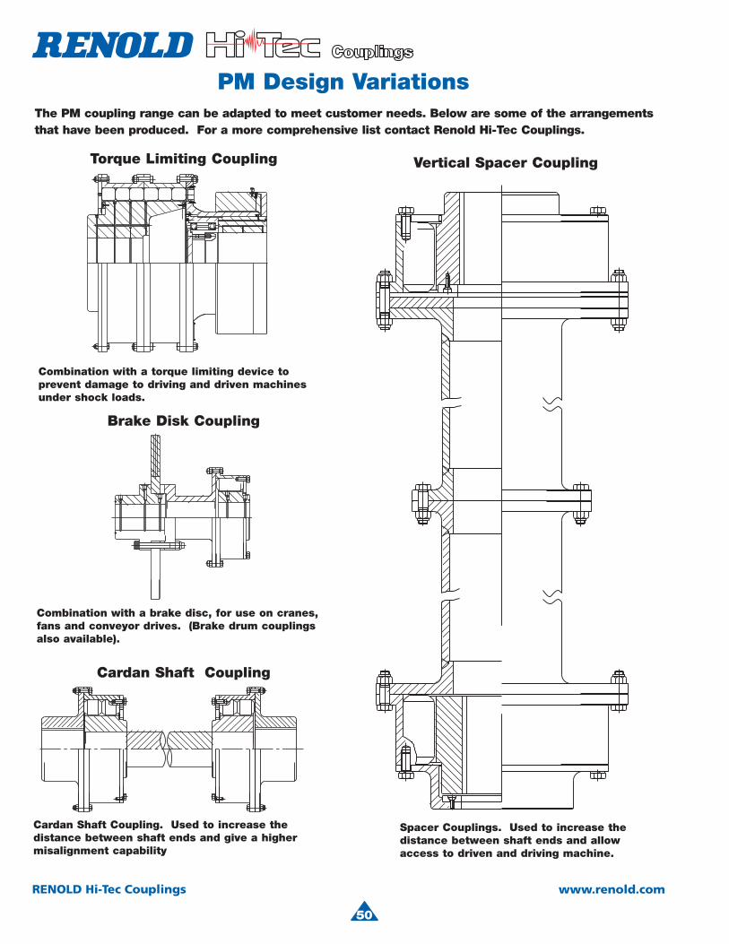
50
RENOLD Hi-Tec Couplings www.renold.com
PM Design VariationsThe PM coupling range can be adapted to meet customer needs. Below are some of the arrangements that have been produced. For a more comprehensive list contact Renold Hi-Tec Couplings.
Combination with a brake disc, for use on cranes, fans and conveyor drives. (Brake drum couplings also available).
Combination with a torque limiting device to prevent damage to driving and driven machinesunder shock loads.
Spacer Couplings. Used to increase thedistance between shaft ends and allowaccess to driven and driving machine.
Cardan Shaft Coupling. Used to increase the distance between shaft ends and give a highermisalignment capability
Torque Limiting Coupling Vertical Spacer Coupling
Brake Disk Coupling
Cardan Shaft Coupling

4
51
RENOLD Hi-Tec Couplings www.renold.com
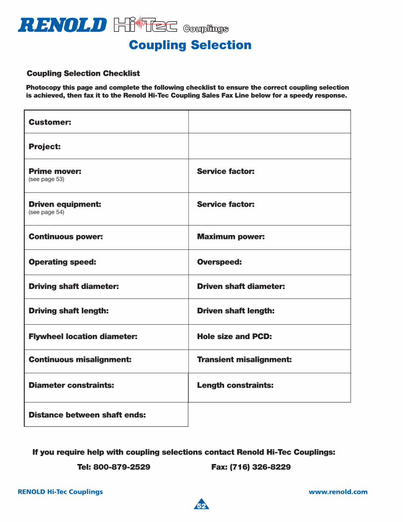
52
RENOLD Hi-Tec Couplings www.renold.com
Coupling Selection
Customer:
Project:
Prime mover:(see page 53)
Service factor:
Service factor:
Continuous power: Maximum power:
Operating speed: Overspeed:
Driving shaft diameter: Driven shaft diameter:
Driving shaft length: Driven shaft length:
Driven equipment:(see page 54)
Flywheel location diameter: Hole size and PCD:
Continuous misalignment: Transient misalignment:
Diameter constraints: Length constraints:
Distance between shaft ends:
If you require help with coupling selections contact Renold Hi-Tec Couplings:
Tel: 800-879-2529 Fax: (716) 326-8229
Photocopy this page and complete the following checklist to ensure the correct coupling selectionis achieved, then fax it to the Renold Hi-Tec Coupling Sales Fax Line below for a speedy response.
Coupling Selection Checklist
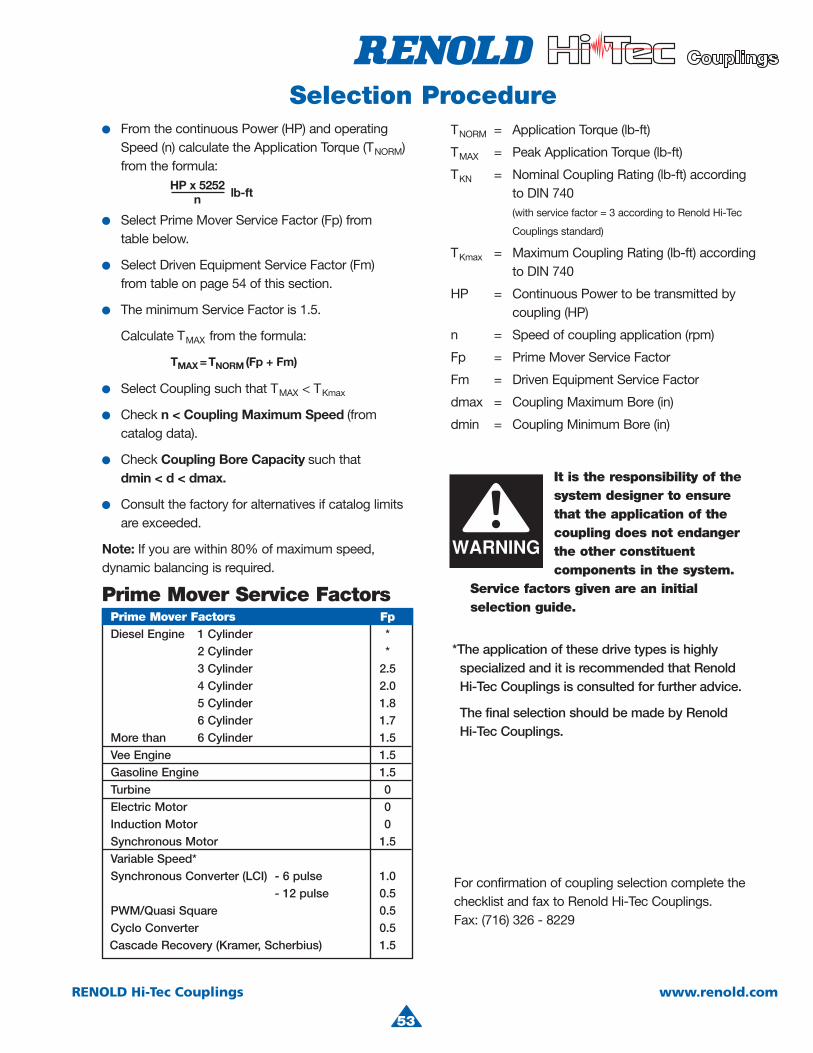
4
53
RENOLD Hi-Tec Couplings www.renold.com
Selection Procedure
Prime Mover Service Factors
HP x 5252n lb-ft
TMAX =TNORM (Fp + Fm)
● From the continuous Power (HP) and operating Speed (n) calculate the Application Torque (TNORM)from the formula:
● Select Coupling such that T MAX < TKmax
● Check n < Coupling Maximum Speed (fromcatalog data).
● Check Coupling Bore Capacity such thatdmin < d < dmax.
● Consult the factory for alternatives if catalog limits are exceeded.
Note: If you are within 80% of maximum speed, dynamic balancing is required.
● Select Prime Mover Service Factor (Fp) fromtable below.
● Select Driven Equipment Service Factor (Fm) from table on page 54 of this section.
● The minimum Service Factor is 1.5.
● Calculate TMAX from the formula:
TNORM = Application Torque (lb-ft)
TMAX = Peak Application Torque (lb-ft)
TKN = Nominal Coupling Rating (lb-ft) accordingto DIN 740(with service factor = 3 according to Renold Hi-Tec
Couplings standard)
TKmax = Maximum Coupling Rating (lb-ft) accordingto DIN 740
HP = Continuous Power to be transmitted by coupling (HP)
n = Speed of coupling application (rpm)
Fp = Prime Mover Service Factor
Fm = Driven Equipment Service Factor
dmax = Coupling Maximum Bore (in)
dmin = Coupling Minimum Bore (in)
*The application of these drive types is highly specialized and it is recommended that Renold Hi-Tec Couplings is consulted for further advice.
The final selection should be made by Renold Hi-Tec Couplings.
For confirmation of coupling selection complete the checklist and fax to Renold Hi-Tec Couplings.Fax: (716) 326 - 8229
Prime Mover Factors FpDiesel Engine 1 Cylinder *
2 Cylinder *3 Cylinder 2.5
4 Cylinder 2.0 5 Cylinder 1.8 6 Cylinder 1.7
More than 6 Cylinder 1.5Vee Engine 1.5Gasoline Engine 1.5Turbine 0Electric Motor 0Induction Motor 0Synchronous Motor 1.5Variable Speed*Synchronous Converter (LCI) - 6 pulse 1.0
- 12 pulse 0.5PWM/Quasi Square 0.5
Cyclo Converter 0.5Cascade Recovery (Kramer, Scherbius) 1.5
It is the responsibility of the system designer to ensure that the application of thecoupling does not endanger the other constituentcomponents in the system.
Service factors given are an initial selection guide.

54
RENOLD Hi-Tec Couplings www.renold.com
Driven Equipment Service Factors
AgitatorsPure liquids 1.5Liquids and solids 2.0Liquids-variable density 2.0
BlowersCentrifugal 1.5Lobe (Roots type) 2.5
Vane 2.0
Brewing and DistillingBottling machinery 1.5Lauter Tub 1.75
Briquetter machines 3.0
Can filling machines 1.5
Cane knives 3.0
Car dumpers 3.0
Car pullers - Intermittent Duty 2.5
Clay working machinery 2.5
Compressors Axial Screw 1.5 Ce ntrifugal 1.5
Lobe 2.5 Reciprocating - multi-cylinder 3.0
Rotary 2.0
Conveyors - uniformly loaded or fed Ap ron 2.0
Assembly 1.5 Belt 1.5
Bucket 2.0 Ch ain 2.0
Flight 2.0Oven 2.5Screw 2.0
Conveyors - heavy dutynot uniformly fed Ap ron 2.0
Assembly 2.0 Belt 2.0
Bucket 2.5 Ch ain 2.5
Flight 2.5Oven 2.5Reciprocating 3.0Screw 3.0Shaker 4.0
Cranes & hoistsAll motions 3.0
CrushersOre 3.0Stone 3.5Sugar 3.5
Dredgers Ca ble reels 2.5 Conveyors 2.0
Cutter head drives 3.5Jig drives 3.5Maneuvring winches 3.0Pumps 3.0Screen drive 3.0
Stackers 3.0Utility winches 2.0
Dynamometer 1.5
ElevatorsBucket 3.0Centrifugal discharge 2.0
Escalators 1.5Freight 2.0Gravity discharge 2.0
FansCentrifugal 1.5Cooling towers 2.0Forced draft 2.0
Induced draft (without damper control) 2.0
FeedersApron 2.0Belt 2.0Disc 2.0
Reciprocating 3.0 Sc rew 2.0
GeneratorsAlternating 1.5Not welding 1.5Welding 2.2
Hammer mills 4.0
Lumber industryBarkers - drum type 3.0
Ed ger feed 2.5 Live rolls 2.5 Lo g haul-incline 2.5 Log haul-well type 2.5 Off bearing rolls 2.5 Planer feed chains 2.0 Pl aner floor chains 2.0
Planer tilting hoist 2.0 Sawing machine 2.0
Slab conveyor 2.0Sorting table 2.0Trimmer feed 2.0
Metal manufacture Bar reeling machine 2.5 Cr usher-ore 4.0 Feed rolls * Fo rging machine 2.0 Rolling machine * Roller table * Sh ears 3.0 Tube mill (pilger) * Wire Mill 2.0
Metal millsDrawn bench - carriage 2.5
Drawn bench - main drive 2.5 Fo rming machines 2.5
Slitters 2.0 Ta ble conveyors - non-reversing * - reversing * Wire drawing and flattening machine 2.0 Wire winding machine 2.0
Metal rolling mills Blooming mills * Co ilers - hot mill & cold mill 2.5 Co ld mills *
Cooling mills * Door openers 2.0 Draw benches 2.5 Ed ger drives 2.5
Feed rolls, reversing mills * Fu rnace pushers 2.5 Ho t mills *
Ingot cars 2.0Manipulators 3.0
Merchant mills * Pi ercers 3.0 Pu shers rams 2.5 Reel drives 2.0 Reel drums 2.0 Bar mills * Roughing mill delivery table *
Runout table *Saws - hot, cold 2.0Screwdown drives 2.5
Skelp mills *Slitters 2.0Slabbing mills *Soaking pit cover drives 2.5Straighteners 3.0Table transfer & runabout 2.5Thrust block 3.0Traction drive 2.0Tube conveyor rolls 2.0
Unscramblers 2.5Wire drawing 2.0
Mills, rotary type Ball 2.5
Cement kilns 2.5Dryers and coolers 2.5Kilns 2.5Hammer 3.5Pebble 2.5Pug 3.0Rod 2.5Tumbling barrels 2.5
MiningConveyor - armoured face 3.0
- belt 1.5 - bucket 1.5
- chain 1.75 - screw 1.5 Dintheader 3.0 Fan - ventilation 2.0 Haulages 2.0
Lump breakers 1.5 Pulverizer 2.0 Pump - rotary 2.0 - ram 3.0
- reciprocating 3.0 - centrifugal 1.5 Roadheader 2.0 Shearer - Longwall 2.0 Winder Colliery 2.5
MixersConcrete mixers 2.0
Drum type 2.0
Oil industryChillers 2.0
Oil well pumping 3.0 Paraffin filter press 2.0 Rotary kilns 2.5
Paper mills Barker-auxiliaries hydraulic 3.0 Barker-mechanical 3.5 Barking drum (Spur Gear only) 3.5
Beater and pulper 3.5 Bleacher 2.0 Calenders 2.0 Chippers 2.5
Coaters 2.0 Converting machine (not cutters, platers) 2.0
Couch 2.0Cutters, platers 3.0
Cylinders 2.0Dryers 2.0Felt stretcher 2.0
Felt whipper 2.0 Jordans 2.25 Line shaft 2.0
Log haul 2.5Presses 2.5
Pulp grinder 3.5 Reel 2.0
Stock chests 2.0 Suction roll 2.0 Washers and thickeners 2.0
Winders 2.0
Printing presses 2.0
PropellerMarine - fixed pitch 2.0
- controllable pitch 2.0
Pullers Barge haul 2.5
Pumps Centrifugal 1.5 Reciprocating - double acting 3.0 single acting - 1 or 2 cylinders 3.0 3 or more cylinders 3.0 Rotary - gear, lobe, vane 2.0
Rubber industryMixed - banbury 3.0Rubber calender 2.0
Rubber mill (2 or more) 2.5 Sheeter 2.5
Tire building machines 2.5Tire and tube press openers 2.0
Tubers and strainer 2.5
ScreensAir washing 1.5
Grizzly 2.5 Rotary, stone or gravel 2.0 Travelling water intake 1.5 Vibrating 2.5
Sewage disposal equipment 2.0
Textile industry 2.0
Windless 2.5* Use 1.75 with motor cut-out power rating
Application Typical Driven Equipment
Factor(Fm)
Application Typical Driven Equipment
Factor(Fm)
Application Typical Driven Equipment
Factor(Fm)
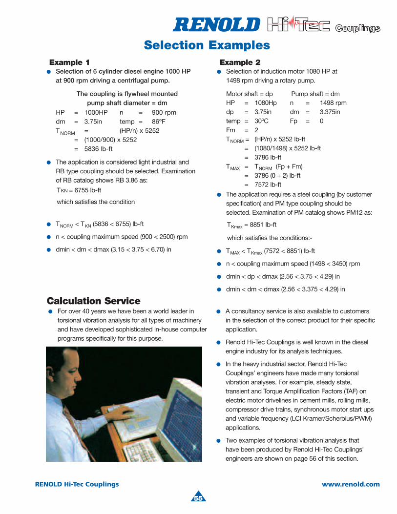
4
55
RENOLD Hi-Tec Couplings www.renold.com
● For over 40 years we have been a world leader in torsional vibration analysis for all types of machinery and have developed sophisticated in-house computer programs specifically for this purpose.
● A consultancy service is also available to customers in the selection of the correct product for their specific application.
● Renold Hi-Tec Couplings is well known in the diesel engine industry for its analysis techniques.
● In the heavy industrial sector, Renold Hi-TecCouplings’ engineers have made many torsional vibration analyses. For example, steady state, transient and Torque Amplification Factors (TAF) on electric motor drivelines in cement mills, rolling mills, compressor drive trains, synchronous motor start ups and variable frequency (LCI Kramer/Scherbius/PWM) applications.
● Two examples of torsional vibration analysis that have been produced by Renold Hi-Tec Couplings’ engineers are shown on page 56 of this section.
Selection Examples
● Selection of 6 cylinder diesel engine 1000 HPat 900 rpm driving a centrifugal pump.
● The application is considered light industrial and RB type coupling should be selected. Examinationof RB catalog shows RB 3.86 as:
● TNORM < TKN (5836 < 6755) lb-ft
● n < coupling maximum speed (900 < 2500) rpm
● dmin < dm < dmax (3.15 < 3.75 < 6.70) in
The coupling is flywheel mountedpump shaft diameter = dm
HP = 1000HP n = 900 rpmdm = 3.75in temp = 86ºFTNORM = (HP/n) x 5252
= (1000/900) x 5252= 5836 lb-ft
TKmax = 8851 lb-ft
which satisfies the conditions:-
● Selection of induction motor 1080 HP at1498 rpm driving a rotary pump.
● The application requires a steel coupling (by customerspecification) and PM type coupling should be selected. Examination of PM catalog shows PM12 as:
● TMAX < TKmax (7572 < 8851) lb-ft
● n < coupling maximum speed (1498 < 3450) rpm
● dmin < dp < dmax (2.56 < 3.75 < 4.29) in
● dmin < dm < dmax (2.56 < 3.375 < 4.29) in
Motor shaft = dp Pump shaft = dmHP = 1080Hp n = 1498 rpmdp = 3.75in dm = 3.375intemp = 30ºC Fp = 0Fm = 2TNORM = (HP/n) x 5252 lb-ft = (1080/1498) x 5252 lb-ft
= 3786 lb-ftTMAX = TNORM (Fp + Fm) = 3786 (0 + 2) lb-ft = 7572 lb-ft
Calculation Service
Example 1 Example 2
which satisfies the condition
TKN = 6755 lb-ft

56
RENOLD Hi-Tec Couplings www.renold.com
Illustrated below are two different types of transient torsional vibration analysis that can be produced by Renold Hi-Tec Couplings’ engineers.
This ensures optimum solutions are reached by the correct selection of torsional stiffness and damping characteristics of the coupling.
Synchronous resonance and synchronous convertor (LCI) examples are shown, however, Renold Hi-Tec Couplings’ experience also includes: Diesel drives, Torque Amplification, electrical speed control devices, PWM, Scherbius/Kramer, short-circuit and any re-connection of electrical circuits on the mechanical systems.
Transient Analysis
Since June 1962 we have engineered flexible couplings for synchronous motor applications to reduce, by damping, the damaging vibratory torques imposed into the system when accelerating through the first resonant frequency. See Tables A and B.
Calculated Examples
Since 1981 we have been engineering flexible couplings for synchronous convertor (LCI) drives to control the forced mode conditions through the first natural frequency by judicial selection of torsional stiffness and damping. See Tables C and D.
Table C shows a typical motor/fan system connected rigidly (or through a gear or membrane coupling) when damaging torques would have been experienced in the motor shaft.
Table D shows the equivalent Renold Hi-Tec Couplings’ engineered solution using a PM coupling.
Table B shows the same system connected by a DCB coupling. PM type couplings are also used in such applications.
Table B
Spee
d-
(RPM
)Co
uplin
gTo
rque
(KNm
)
120
60
0
-60
-120
1620
1260
900
540
180
1.500 4.500 7.500 10.500 13.500 16.500 19.500 22.500Acceleration time in seconds
Table D
Spee
d-
(RPM
)Co
uplin
gTo
rque
Nm(*
10**
2)
320
160
0
-160
-320
180
140
100
60
20
.250 .750 1.250 1.750 2.250 2.750 3.250 3.750Acceleration time in seconds
Table C
Spee
d-
(RPM
)Co
uplin
gTo
rque
Nm(*
10**
2)
320
160
0
-160
-320
180
140
100
60
20
.250 .750 1.250 1.750 2.250 2.750 3.250 3.750Acceleration time in seconds
Table A shows vibrating torque experienced in the motor shaft when the system is connected rigidly (or by a gear or membrane coupling) to the driven system.
Table A
Spe
ed-
(RP
M)
Cou
plin
gTo
rque
(KN
m)
120
60
0
-60
-120
1620
1260
900
540
180
1.500 4.500 7.500 10.500 13.500 16.500 19.500 22.500Acceleration time in seconds
Example 1
Example 2
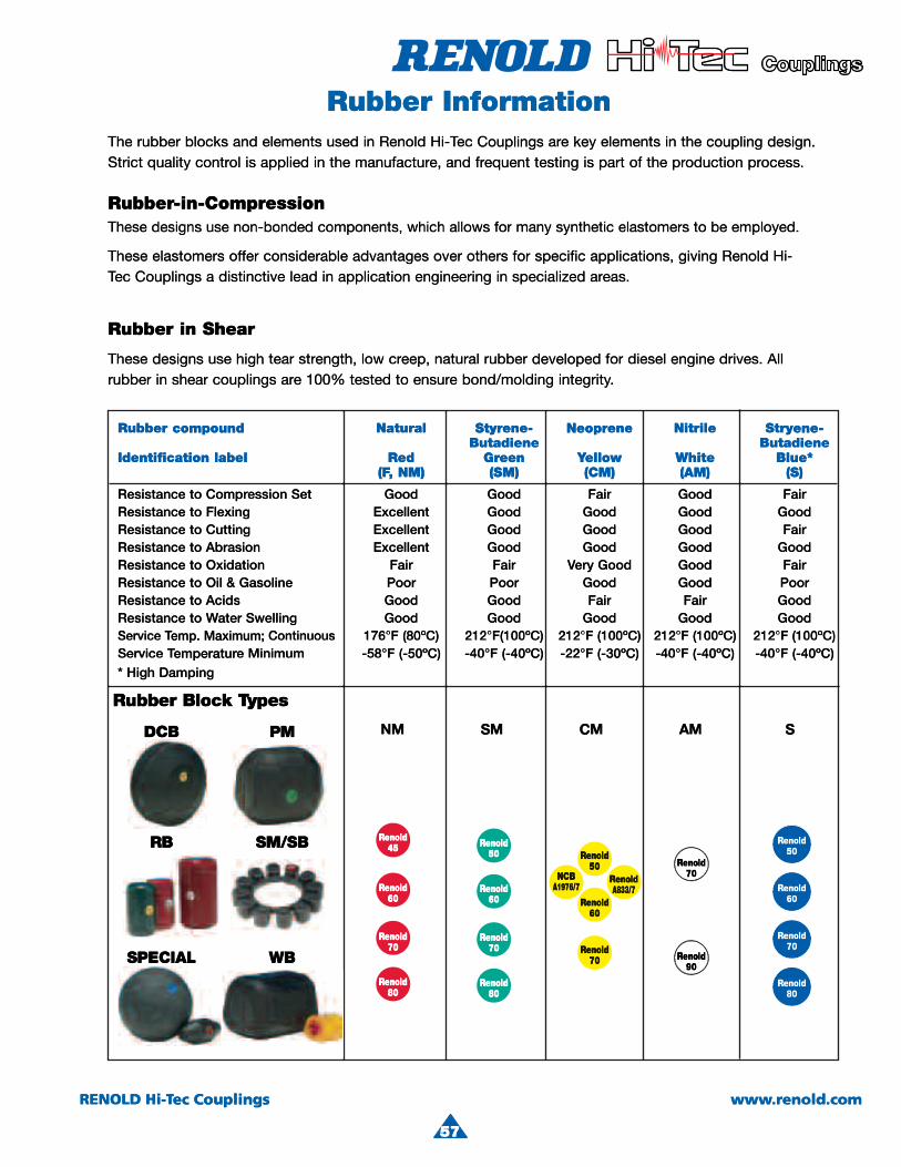
4
57
RENOLD Hi-Tec Couplings www.renold.com
Rubber compound Natural Styrene- Neoprene Nitrile Stryene- Butadiene ButadieneIdentification label Red Green Yellow White Blue*
(F, NM) (SM) (CM) (AM) (S)
Resistance to Compression Set Good Good Fair Good FairResistance to Flexing Excellent Good Good Good GoodResistance to Cutting Excellent Good Good Good FairResistance to Abrasion Excellent Good Good Good GoodResistance to Oxidation Fair Fair Very Good Good FairResistance to Oil & Gasoline Poor Poor Good Good PoorResistance to Acids Good Good Fair Fair GoodResistance to Water Swelling Good Good Good Good GoodService Temp. Maximum; Continuous 176°F (80ºC) 212°F(100ºC) 212°F (100ºC) 212°F (100ºC) 212°F (100ºC)Service Temperature Minimum -58°F (-50ºC) -40°F (-40ºC) -22°F (-30ºC) -40°F (-40ºC) -40°F (-40ºC)* High Damping
The rubber blocks and elements used in Renold Hi-Tec Couplings are key elements in the coupling design. Strict quality control is applied in the manufacture, and frequent testing is part of the production process.
Rubber Information
These designs use non-bonded components, which allows for many synthetic elastomers to be employed.
These elastomers offer considerable advantages over others for specific applications, giving Renold Hi-Tec Couplings a distinctive lead in application engineering in specialized areas.
These designs use high tear strength, low creep, natural rubber developed for diesel engine drives. All rubber in shear couplings are 100% tested to ensure bond/molding integrity.
Rubber-in-Compression
Rubber Block Types
Rubber in Shear
Renold45
Renold60
Renold70
Renold80
Renold50
Renold60
Renold70
Renold80
Renold70
Renold90
Renold50
NCBA1976/7
RenoldA833/7
Renold60
Renold70
NM SM CM AM SDCB PM
RB SM/SB
SPECIAL WB
Renold50
Renold60
Renold70
Renold80
InforRubber rmationruThe
Strict
esehT
TheseCecTTec
Rubb
elementsandblocksubberinappliedisolcontrquality
ocdednob-nonesusngisede
consideraferoffelastomerseinleaddistinctiveaouplings
ession-in-Comprberr-in-Compr
CoupecHi-TTec Renoldinusedequfrande,manufacturthe
rofswollahcihw,stnenopmo
othersoveradvantagesableinengineeringapplicationn
thinelementskeyearplingsoprtheofpartistestinguent
sremotsalecitehtnysynamr
giapplications, specificforeas.arspecialized
design. couplingheocess.production
.deyolpmeebot
Hi-Renoldving
Rubb
Iden
Theserubbe
bbuR
compoundber
labelntification
enstrtearhighusedesignse100earcouplingssheariner
raehSnireb
eStyrNatural
eGrRedButad
(SMNM),(FF,
rubbnaturaleep,crlowngth,bond/meensurtotested0%
NiteneNeoprene-
WhellowYYellowendiene
(A(CM)M)
engdieselfordeveloped ber.integritymolding
yene-Strryene-trile
Blue*hiteButadiene
(S)AM)
Alldrives.gine
ResisResisResisResisResisResisResisResis
ServiServ
SwellingaterWtostanceAcidstostance
Gasoline&OiltostanceOxidationtostanceAbrasiontostanceCuttingtostanceFlexingtostance
SetessionComprtostance
ContinuouMaximum;emp.TTemp. iceMinimumeemperaturTTemperaturice
(),( ,
GooGoodGooGoodPooPoorFaFair
GooExcellentGooExcellentGooExcellentGooGood
us(--40°F(-50ºC)-58°F1(F°212)Cº08(8F°671
(( ))
GoGoododFFairod
GoGoodorGoGooderyVVery irGoGoododGoGoododGoGoododGoFairod
-40°F(-30ºC)-22°F-40ºC)F°212)Cº001(F°212)Cº00
( ))
GoodoodGoodFairPooroodFairood
GoodoodFairood
GoodoodFairood
(-40ºC)-40°F(-40ºC))Cº001(F°212)CCº001(
Hig*
buR
D
pDampinggh
sepyTTykcolBrebb
CBCD MP
BR BS//SMS
(( )
dloneRRe dlR
MN MS
( ))
MC A
( )( )
d
M S
loneRRe
PS
BR BS//SMS
LAICEP BW
4
dloneRRe54
dloneRRe06
dloneRRe07
dloneRRe08
dloneRRe05
dloneRRe06
dloneRRe07
dloneRRe08
neRRe7
neRRe9
dloneRRe05
BCN7/6791A
dloneRRe7/338AA8
dloneRRe06
dloneRRe07
d
d
d
d
dlon07
dlon09
loneRRe05
loneRRe06
loneRRe07
loneRRe08
RENOLD ec CouplingsHi-TTec Couplings
775555
enold.com.rwww

58
RENOLD Hi-Tec Couplings www.renold.com
Damping CharacteristicsCoupling damping varies directly with torsional stiffness and inversely with frequency for a given rubber grade. This relationship is conventionally described by the dynamic magnifier (M), varying withhardness for the various rubber types.
The rubber compound dynamic magnifier values are shown in the table below.
M = KCω
ψ = AD = 2πAf M
This property may also be expressed as the Damping Energy Ratio or Relative Damping ( ), which isthe ratio of the damping energy (AD), produced mechanically by the coupling during a vibration cycle and converted into heat energy, to the flexible strainenergy (Af), with respect to the mean position.
ψ
tan δ = Cω = IK M
Torque = (k + icω) aeiωt + δ
Deflection = aeiωtδ
Mid TorqueMdm
Deflection
AD
Af
Torq
ue
Mid
Def
lect
ion
Health and Safety at WorkCustomers are reminded that when purchasing Renold Hi-Tec Couplings products, for use at work or otherwise, additional and up-to-date information which is not possible to include in Renold Hi-Tec Couplings publications is available from your local Sales Company in relation to:
(a) guidance on individual product suitability based on the various existing applications of the extensive range of Renold Hi-Tec Couplings products.
(b) guidance on safe and proper use provided that full disclosure is made of the precise details of the intended or existing application. All relevant information should be passed on to the persons engaged in, likely to be affected by, and those responsible for the use of the product. Nothing contained in this publication shall constitute a partof any contract, expressed or implied.
Product PerformanceThe performance levels and tolerances of our product stated in this catalog (including without limitation, serviceability, wearlife, resistance to fatigue, corrosion protection) have been shown in a program of testing and quality control in accordance with Renold Hi-Tec Couplings, independent and or international standard recommendations.
No representation warranty or condition is given that our products shall meet the stated performance levels or tolerances for any given application outside the controlled environment required by such tests.
Guidance NotesWhile all reasonable care in compiling the information contained in this catalog is taken, no responsibility is accepted for printing errors. All information contained in this catalog is subject to change after the date of publication.
Illustrations - The illustrations used in this catalog represent the type of product described but the goods supplied may vary in some detail from those illustrated.
Specifications - The right is reserved to make modifications to design and dimensions as published in this catalog to meet manufacturing conditions and developments in design and materials.
Renold Hi-Tec Couplings - Products can be supplied by Renold Hi-Tec Couplings and Renold companies or representatives around the world on the standard terms and conditions of sale of the company or representative from which the products are purchased.
Copyright - All matter in this publication is the copyright of Renold Inc. and may not be reproduced in whole or part without written permission.
Rubber grade MNM 45 15SM 50 10SM 60 8SM 70 6SM 80 4
Where C = Specific Damping (lb-ft s/rad)
K = Torsional Stiffness (lb-ft/rad)
ω = Frequency (Rad/s)
M = Dynamic Magnifier
δ = Phase Angle (Rad)
ψ = Damping Energy Ratio
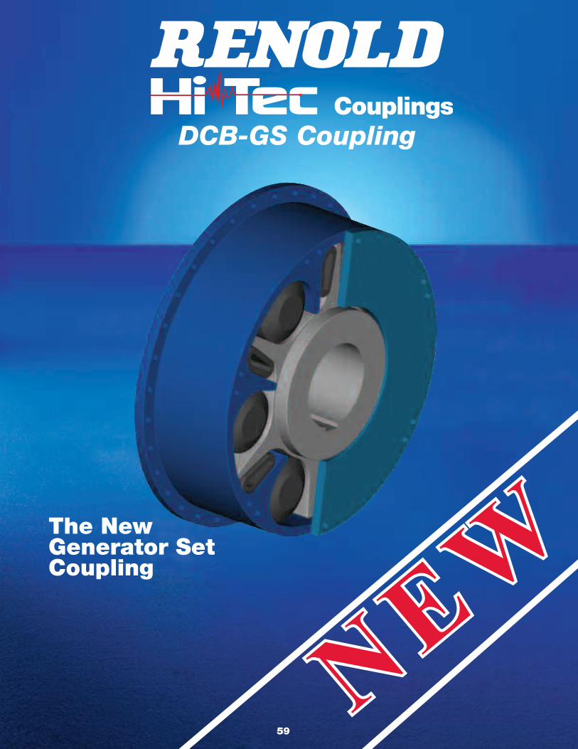
DCB-GS Coupling
NEW
NEWThe New
Generator SetCoupling
59
Renold Couplings & Gears100 Bourne StreetWestfield, NY 14787-9706Tel: +1 800 879 2529Fax: +1 716 326 8229Web: www.renold.comE-mail: [email protected]
112 Parkinson LaneHalifax HX1 3QHUnited KingdomTel: +44 (0) 1422 255000Fax: +44 (0) 1422 255100E-mail: [email protected]
3mDPI 5/07 PRINTED IN USA
www.renold.com
Superior Coupling Technology