Embed Size (px)
Citation preview
M-2
COUPLINGS
YOU’LL ALWAYS MAKE THE CORRECTCONNECTION WHEN YOU SPECIFYOPTIMUM-QUALITY EPT COUPLINGS.
Choose From More Than 25,000 CombinationsOf Types, Sizes And Bores...Most Available From Stock
KOP-FLEX research and development, design engineering and manufacturing technology employs the latest CAD/CAE/CAM technology. The use of space age materials... provide reliable products of the highest quality, to stringentISO 9001 Quality Standards. These rugged couplings are widely utilized in petrochemical, process, pulp andpaper and heavy metal producing facilities, and many other services.
Industry World-Wide Depends On KOP-FLEX ® Couplings For A Broad Range Of Heavy-Duty Applications...
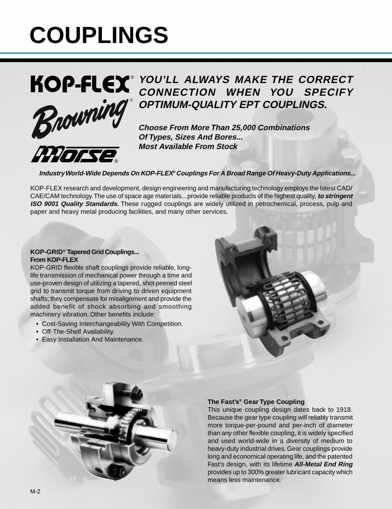
The Fast’s ® Gear Type CouplingThis unique coupling design dates back to 1918.Because the gear type coupling will reliably transmitmore torque-per-pound and per-inch of diameterthan any other flexible coupling, it is widely specifiedand used world-wide in a diversity of medium toheavy-duty industrial drives. Gear couplings providelong and economical operating life, and the patentedFast’s design, with its lifetime All-Metal End Ringprovides up to 300% greater lubricant capacity whichmeans less maintenance.
KOP-GRID® Tapered Grid Couplings...From KOP-FLEXKOP-GRID flexible shaft couplings provide reliable, long-life transmission of mechanical power through a time anduse-proven design of utilizing a tapered, shot peened steelgrid to transmit torque from driving to driven equipmentshafts; they compensate for misalignment and provide theadded benefit of shock absorbing and smoothingmachinery vibration. Other benefits include:
• Cost-Saving Interchangeability With Competition.• Off-The-Shelf Availability.• Easy Installation And Maintenance.
®
®
®
M-3
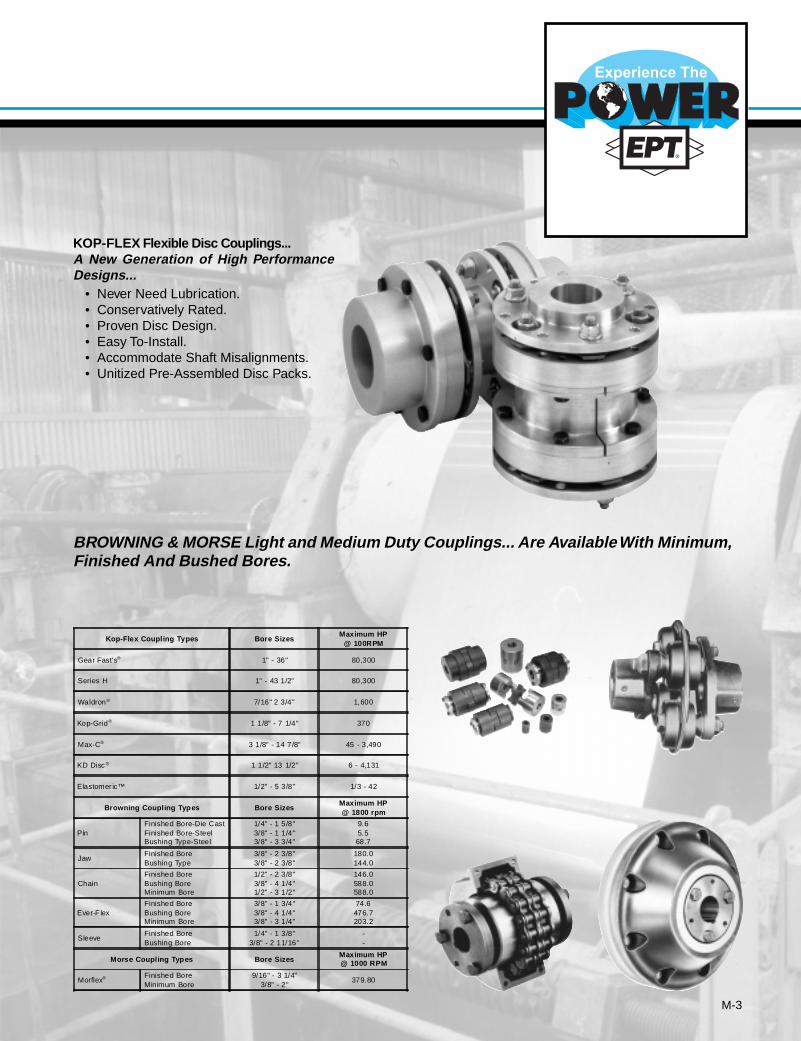
KOP-FLEX Flexible Disc Couplings...A New Generation of High PerformanceDesigns...
• Never Need Lubrication.• Conservatively Rated.• Proven Disc Design.• Easy To-Install.• Accommodate Shaft Misalignments.• Unitized Pre-Assembled Disc Packs.
BROWNING & MORSE Light and Medium Duty Couplings... Are Available With Minimum,Finished And Bushed Bores.
Kop-Flex Coupling Types Bore SizesMaximum HP
@ 100RPM
Gear Fast's® 1" - 36" 80,300
Series H 1" - 43 1/2" 80,300
Waldron® 7/16" 2 3/4" 1,600
Kop-Grid® 1 1/8" - 7 1/4" 370
Max-C® 3 1/8" - 14 7/8" 45 - 3,490
KD Disc ® 1 1/2" 13 1/2" 6 - 4,131
Elastomer ic™ 1/2" - 5 3/8" 1/3 - 42
Browning Coupling Types Bore SizesMaximum HP@ 1800 rpm
PinFinished Bore-Die CastFinished Bore-SteelBushing Type-Steel
1/4" - 1 5/8"3/8" - 1 1/4"3/8" - 3 3/4"
9.65.568.7
JawFinished BoreBushing Type
3/8" - 2 3/8"3/8" - 2 3/8"
180.0144.0
ChainFinished BoreBushing BoreMinimum Bore
1/2" - 2 3/8"3/8" - 4 1/4"1/2" - 3 1/2"
146.0588.0588.0
Ever-F lexFinished BoreBushing BoreMinimum Bore
3/8" - 1 3/4"3/8" - 4 1/4"3/8" - 3 1/4"
74.6476.7203.2
SleeveFinished BoreBushing Bore
1/4" - 1 3/8"3/8" - 2 11/16"
--
Morse Coupling Types Bore SizesMaximum HP@ 1000 RPM
Morflex® Finished BoreMinimum Bore
9/16" - 3 1/4"3/8" - 2"
379.80
M-4
COUPLINGS
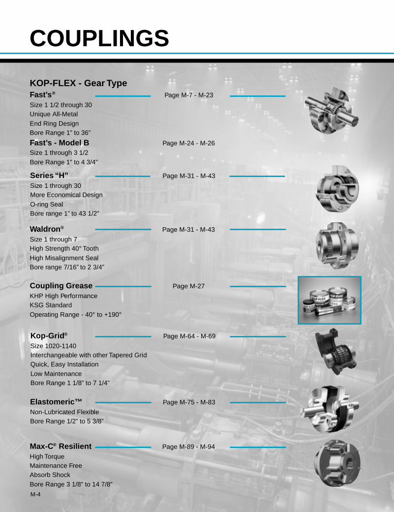
KOP-FLEX - Gear TypeFast’s ® Page M-7 - M-23
Size 1 1/2 through 30Unique All-Metal
End Ring DesignBore Range 1” to 36”
Fast’s - Model B Page M-24 - M-26
Size 1 through 3 1/2
Bore Range 1” to 4 3/4”
Series “H” Page M-31 - M-43
Size 1 through 30More Economical Design
O-ring SealBore range 1” to 43 1/2”
Waldron ® Page M-31 - M-43
Size 1 through 7High Strength 40° Tooth
High Misalignment SealBore range 7/16” to 2 3/4”
Coupling Grease Page M-27
KHP High PerformanceKSG Standard
Operating Range - 40° to +190°
Kop-Grid ® Page M-64 - M-69
Size 1020-1140Interchangeable with other Tapered GridQuick, Easy Installation
Low MaintenanceBore Range 1 1/8” to 7 1/4”
Elastomeric™ Page M-75 - M-83
Non-Lubricated FlexibleBore Range 1/2” to 5 3/8”
Max-C® Resilient Page M-89 - M-94
High TorqueMaintenance FreeAbsorb Shock
Bore Range 3 1/8” to 14 7/8”
M-5
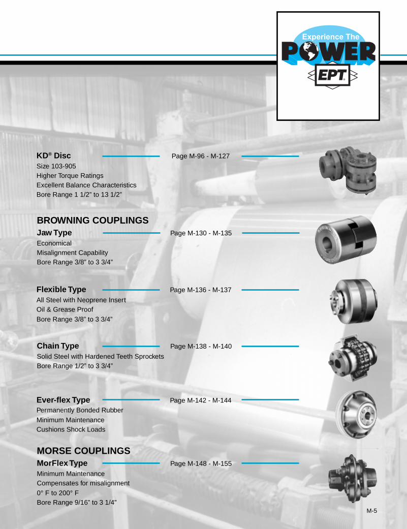
KD® Disc Page M-96 - M-127
Size 103-905Higher Torque RatingsExcellent Balance CharacteristicsBore Range 1 1/2” to 13 1/2”
BROWNING COUPLINGSJaw Type Page M-130 - M-135
EconomicalMisalignment CapabilityBore Range 3/8” to 3 3/4”
Flexible Type Page M-136 - M-137
All Steel with Neoprene InsertOil & Grease Proof
Bore Range 3/8” to 3 3/4”
Chain Type Page M-138 - M-140
Solid Steel with Hardened Teeth SprocketsBore Range 1/2” to 3 3/4”
Ever-flex Type Page M-142 - M-144
Permanently Bonded Rubber
Minimum MaintenanceCushions Shock Loads
MORSE COUPLINGSMorFlex Type Page M-148 - M-155
Minimum MaintenanceCompensates for misalignment
0° F to 200° FBore Range 9/16” to 3 1/4”
M-6
®
RM Series
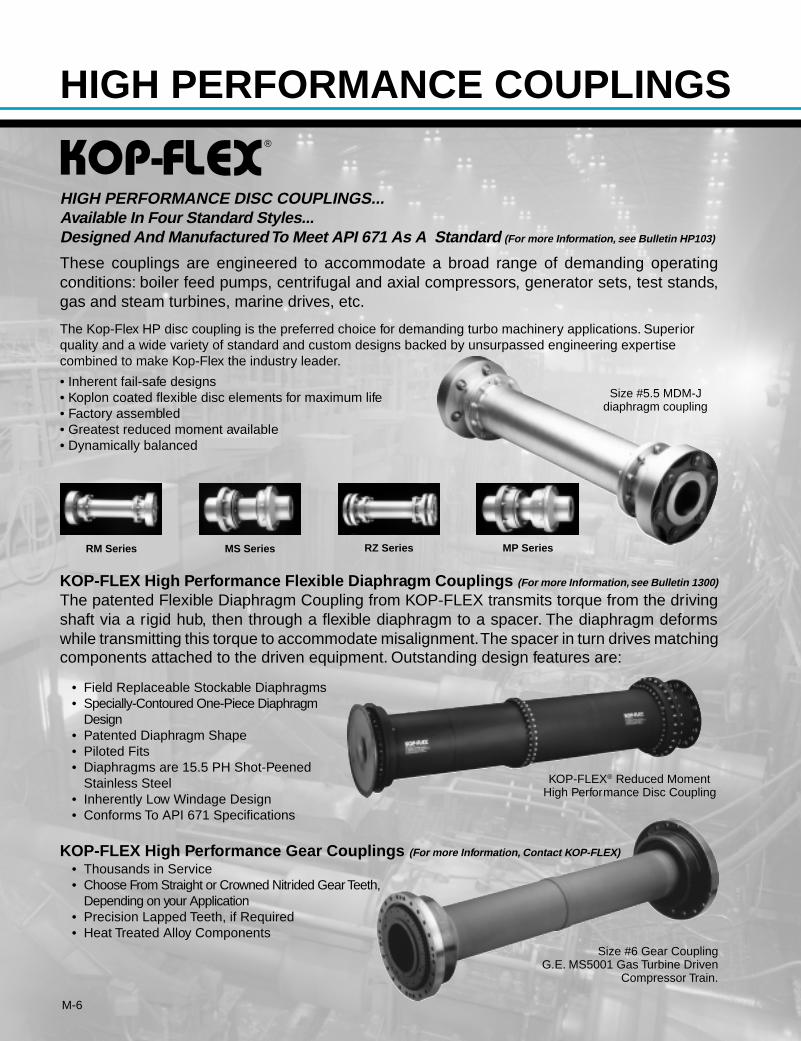
These couplings are engineered to accommodate a broad range of demanding operatingconditions: boiler feed pumps, centrifugal and axial compressors, generator sets, test stands,gas and steam turbines, marine drives, etc.
The Kop-Flex HP disc coupling is the preferred choice for demanding turbo machinery applications. Superiorquality and a wide variety of standard and custom designs backed by unsurpassed engineering expertisecombined to make Kop-Flex the industry leader.
• Inherent fail-safe designs• Koplon coated flexible disc elements for maximum life• Factory assembled• Greatest reduced moment available• Dynamically balanced
KOP-FLEX High Performance Flexible Diaphragm Couplings (For more Information, see Bulletin 1300)
The patented Flexible Diaphragm Coupling from KOP-FLEX transmits torque from the drivingshaft via a rigid hub, then through a flexible diaphragm to a spacer. The diaphragm deformswhile transmitting this torque to accommodate misalignment. The spacer in turn drives matchingcomponents attached to the driven equipment. Outstanding design features are:
• Field Replaceable Stockable Diaphragms• Specially-Contoured One-Piece Diaphragm
Design• Patented Diaphragm Shape• Piloted Fits• Diaphragms are 15.5 PH Shot-Peened
Stainless Steel• Inherently Low Windage Design• Conforms To API 671 Specifications
HIGH PERFORMANCE DISC COUPLINGS...Available In Four Standard Styles...Designed And Manufactured To Meet API 671 As A Standard (For more Information, see Bulletin HP103)
MS Series RZ Series MP Series
KOP-FLEX® Reduced MomentHigh Performance Disc Coupling
Size #5.5 MDM-Jdiaphragm coupling
KOP-FLEX High Performance Gear Couplings (For more Information, Contact KOP-FLEX)
• Thousands in Service• Choose From Straight or Crowned Nitrided Gear Teeth,
Depending on your Application• Precision Lapped Teeth, if Required• Heat Treated Alloy Components
Size #6 Gear CouplingG.E. MS5001 Gas Turbine Driven
Compressor Train.
HIGH PERFORMANCE COUPLINGS
M-7
Index:Page
HOW TO ORDER ....................................... M-9Fast’s
Technical Advantages ................... M-8, M-9Service Factors ................................... M-10Selection Procedure ............................ M-11Dynamic Balancng Guide ................... M-11Full Flex Coupling ........... M-12, M-14, M-14Fastener Data ..................................... M-13Spacer Coupling ................................. M-15Flex-Rigid Coupling ............................. M-16Floating Shaft Coupling ....................... M-17Mill Motor Coupling .................... M18, M-19Limited End Float Coupling ................. M-20Rigid Coupling..................................... M-20Short Slide Coupling ........................... M-21Medium Slide Coupling ....................... M-22Long Slide Coupling ............................ M-23
Model BTechnical Advantages ......................... M-24Flex Rigid Coupling ............................. M-24Floating Shaft Coupling ....................... M-24Full Flex Coupling ............................... M-25Limited End Float Coupling ................. M-26Spacer Coupling ................................. M-26
Grease ..................................................... M-27
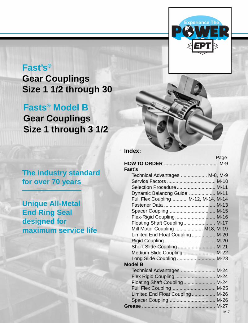
The industry standardfor over 70 years
Unique All-MetalEnd Ring Sealdesigned formaximum service life
Fast’s ®
Gear CouplingsSize 1 1/2 through 30
Fasts ® Model BGear CouplingsSize 1 through 3 1/2
®
M-8
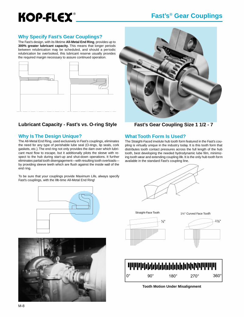
Why Specify Fast’s Gear Couplings?The Fast’s design, with its lifetime All-Metal End Ring , provides up to300% greater lubricant capacity. This means that longer periodsbetween relubrication may be scheduled, and should a periodicrelubrication be overlooked, this lubricant reserve usually providesthe required margin necessary to assure continued operation.
Fast’s ® Gear Couplings
Lubricant Capacity - Fast’s vs. O-ring Style
Why Is The Design Unique?The All-Metal End Ring, used exclusively in Fast’s couplings, eliminatesthe need for any type of perishable lube seal (O-rings, lip seals, corkgaskets, etc.). The end ring not only provides the dam over which lubri-cant must flow to escape, but it additionally pilots the sleeve with re-spect to the hub during start-up and shut-down operations. It furthereliminates partial tooth disengagement—with resulting tooth overloads—by providing sleeve teeth which are flush against the inside wall of theend ring.
To be sure that your couplings provide Maximum Life, always specifyFast’s couplings, with the life-time All-Metal End Ring!
Fast’s Gear Coupling Size 1 1/2 - 7
What Tooth Form Is Used?The Straight-Faced involute hub tooth form featured in the Fast’s cou-pling is virtually unique in the industry today. It is this tooth form thatdistributes tooth contact pressures across the full length of the hubtooth, best developing the needed hydrodynamic lube film, minimiz-ing tooth wear and extending coupling life. It is the only hub tooth formavailable in the standard Fast’s coupling line.
Straight-Face Tooth 1½° Curved Face Tooth
1
Tooth Motion Under Misalignment
®
M-9
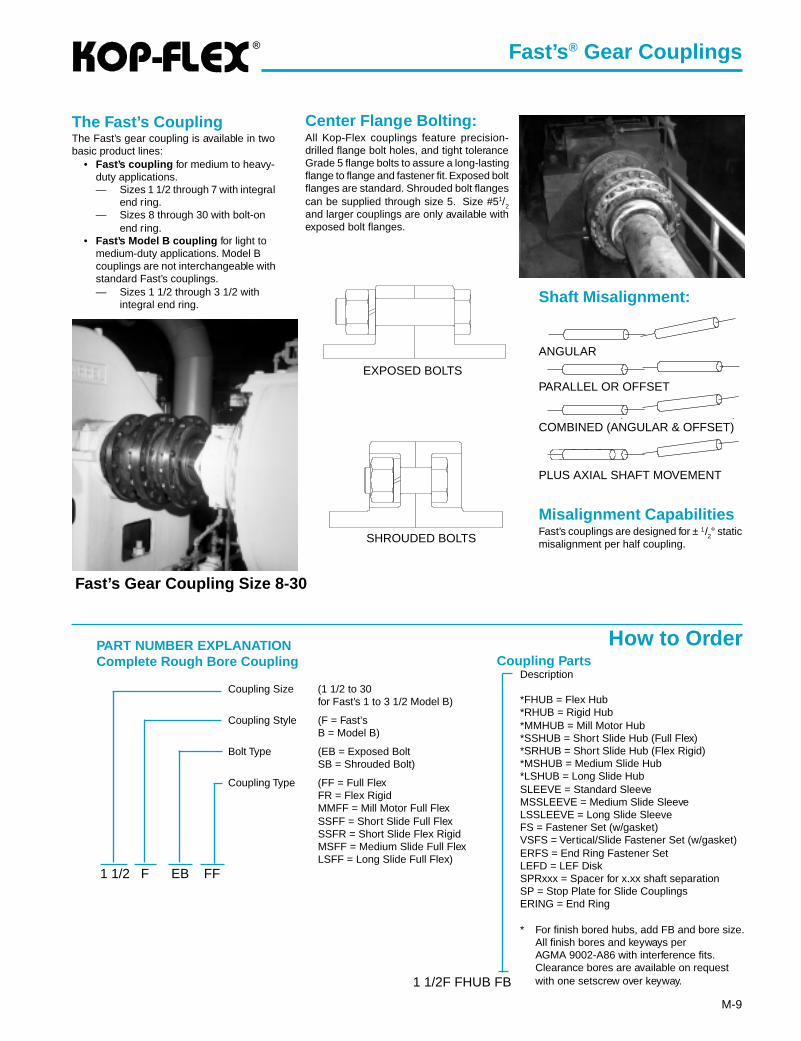
Center Flange Bolting:All Kop-Flex couplings feature precision-drilled flange bolt holes, and tight toleranceGrade 5 flange bolts to assure a long-lastingflange to flange and fastener fit. Exposed boltflanges are standard. Shrouded bolt flangescan be supplied through size 5. Size #51/2
and larger couplings are only available withexposed bolt flanges.
Shaft Misalignment:
Misalignment CapabilitiesFast’s couplings are designed for ± 1/2° staticmisalignment per half coupling.
Fast’s ® Gear Couplings
SHROUDED BOLTS
EXPOSED BOLTS
The Fast’s CouplingThe Fast’s gear coupling is available in twobasic product lines:
• Fast’s coupling for medium to heavy-duty applications.— Sizes 1 1/2 through 7 with integral
end ring.— Sizes 8 through 30 with bolt-on
end ring.• Fast’s Model B coupling for light to
medium-duty applications. Model Bcouplings are not interchangeable withstandard Fast’s couplings.— Sizes 1 1/2 through 3 1/2 with
integral end ring.
Fast’s Gear Coupling Size 8-30
PART NUMBER EXPLANATIONComplete Rough Bore Coupling
Coupling Size (1 1/2 to 30for Fast’s 1 to 3 1/2 Model B)
Coupling Style (F = Fast’sB = Model B)
Bolt Type (EB = Exposed BoltSB = Shrouded Bolt)
Coupling Type (FF = Full FlexFR = Flex RigidMMFF = Mill Motor Full FlexSSFF = Short Slide Full FlexSSFR = Short Slide Flex RigidMSFF = Medium Slide Full FlexLSFF = Long Slide Full Flex)
1 1/2 F EB FF
Description
*FHUB = Flex Hub*RHUB = Rigid Hub*MMHUB = Mill Motor Hub*SSHUB = Short Slide Hub (Full Flex)*SRHUB = Short Slide Hub (Flex Rigid)*MSHUB = Medium Slide Hub*LSHUB = Long Slide HubSLEEVE = Standard SleeveMSSLEEVE = Medium Slide SleeveLSSLEEVE = Long Slide SleeveFS = Fastener Set (w/gasket)VSFS = Vertical/Slide Fastener Set (w/gasket)ERFS = End Ring Fastener SetLEFD = LEF DiskSPRxxx = Spacer for x.xx shaft separationSP = Stop Plate for Slide CouplingsERING = End Ring
* For finish bored hubs, add FB and bore size.All finish bores and keyways perAGMA 9002-A86 with interference fits.Clearance bores are available on requestwith one setscrew over keyway.1 1/2F FHUB FB
Coupling Parts
How to Order
ANGULAR
PARALLEL OR OFFSET
COMBINED (ANGULAR & OFFSET)
PLUS AXIAL SHAFT MOVEMENT

®
M-10
Fast’s ® Gear Couplings
Service Factors
TypicalApplication Ser vice
FactorAGITATORS
Pure Liquids .......................................................... 1.0Liquids & Solids .................................................... 1.25Liquids — Variable Density ................................... 1.25
BLOWERSCentrifugal ............................................................. 1.0Lobe ...................................................................... 1.5Vane ...................................................................... 1.25
BRIQUETTE MACHINES ........................................... 2.0CAR PULLERS — Intermittent Duty .......................... 1.5COMPRESSORS
Centrifugal ............................................................. 1.0Centriaxial ............................................................. 1.25Lobe ...................................................................... 1.5Reciprocating — Multi-Cylinder ............................ 2.0
CONVEYORS — LIGHT DUTY UNIFORMLY FEDApron, Bucket, Chain, Flight, Screw ..................... 1.25Assembly, Belt ....................................................... 1.0Oven ...................................................................... 1.5
CONVEYORS — HEAVY DUTY NOT UNIFORMLY FEDApron, Bucket, Chain, Flight, Oven ....................... 1.5Assembly, Belt ....................................................... 1.25Reciprocating, Shaker ........................................... 2.5
CRANES AND HOISTS (NOTE 1 and 2)Main hoists, Reversing .......................................... 2.5Skip Hoists, Trolley & Bridge Drives ...................... 2.0Slope ..................................................................... 2.0
CRUSHERSOre, Stone ............................................................. 3.0
DREDGESCable Reels ........................................................... 1.75Conveyors ............................................................. 1.5Cutter Head Jig Drives .......................................... 2.5Maneuvering Winches ........................................... 1.75Pumps ................................................................... 1.75Screen Drives ........................................................ 1.75Stackers ................................................................ 1.75Utility Winches ....................................................... 1.5
ELEVATORS (NOTE 2)Bucket ................................................................... 1.75Centrifugal & Gravity Discharge ........................... 1.5Escalators ............................................................. 1.5Freight ................................................................... 2.5
FANSCentrifugal ............................................................. 1.0Cooling Towers ...................................................... 1.5Forced Draft .......................................................... 1.5Induced Draft without Damper Control ............................................................... 2.0
FEEDERSApron, Belt, Disc, Screw ....................................... 1.25Reciprocating ........................................................ 2.5
TypicalApplication Ser vice
FactorGENERATORS —
(Not Welding) ........................................................... 1.0HAMMER MILLS ........................................................ 2.0LAUNDRY WASHERS —
Reversing ............................................................. 2.0LAUNDRY TUMBLERS ............................................. 2.0LINE SHAFT .............................................................. 1.5LUMBER INDUSTRY
Barkers — Drum Type ............................................. 2.0Edger Feed .............................................................. 2.0Live Rolls ................................................................. 2.0Log Haul — Incline .................................................. 2.0Log Haul — Well type .............................................. 2.0Off Bearing Rolls ...................................................... 2.0Planer Feed Chains ................................................. 1.75Planer Floor Chains ................................................. 1.75Planer Tilting Hoist ................................................... 1.75Slab Conveyor .......................................................... 1.5Sorting Table ............................................................ 1.5Trimmer Feed ........................................................... 1.75
MARINE PROPULSIONMain Drives .............................................................. 2.0
MACHINE TOOLSBending Roll ............................................................ 2.0Plate Planer ............................................................. 1.5Punch Press — Gear Driven ................................... 2.0Tapping Machines .................................................... 2.5Other Machine Tools Main Drives .......................................................... 1.5 Auxiliary Drives .................................................... 1.25
METAL MILLSDraw Bench — Carriage .......................................... 2.0Draw Bench — Main Drive ...................................... 2.0Forming Machines ................................................... 2.0Slitters ...................................................................... 1.5Table Conveyors Non-Reversing ..................................................... 2.25 Reversing ............................................................. 2.5Wire Drawing & Flattening Machine ........................ 2.0Wire Winding Machine ............................................. 1.75
METAL ROLLING MILLS (NOTE 1)Blooming Mills .......................................................... *Coilers, hot mill ........................................................ 2.0Coilers, cold mill ....................................................... 1.25Cold Mills ................................................................. 2.0Cooling Beds ........................................................... 1.75Door Openers .......................................................... 2.0Draw Benches .......................................................... 2.0Edger Drives ............................................................ 1.75Feed Rolls, Reversing Mills ..................................... 3.5Furnace Pushers ..................................................... 2.5Hot Mills ................................................................... 3.0Ingot Cars ................................................................ 2.5Kick-outs .................................................................. 2.5Manipulators ............................................................ 3.0Merchant Mills .......................................................... 3.0Piercers .................................................................... 3.0Pusher Rams ........................................................... 2.5Reel Drives .............................................................. 1.75Reel Drums .............................................................. 2.0Reelers ..................................................................... 3.0Rod and Bar Mills .................................................... 1.5Roughing Mill Delivery Table ................................... 3.0Runout Tables Reversing ............................................................. 3.0 Non-Reversing ..................................................... 2.0Saws, hot & cold ...................................................... 2.5Screwdown Drives ................................................... 3.0Skelp Mills ................................................................ 3.0Slitters ...................................................................... 3.0Slabbing Mills ........................................................... 3.0Soaking Pit Cover Drives ......................................... 3.0Straighteners ............................................................ 2.5Tables, transfer & runout .......................................... 2.0Thrust Block ............................................................. 3.0Traction Drive ........................................................... 3.0Tube Conveyor Rolls ................................................ 2.5Unscramblers ........................................................... 2.5Wire Drawing ........................................................... 1.5
MILLS, ROTARY TYPEBall ........................................................................... 2.25Dryers & Coolers ..................................................... 2.0Hammer ................................................................... 1.75Kilns ......................................................................... 2.0
TypicalApplication Ser vice
FactorPebble & Rod ........................................................... 2.0Pug ........................................................................... 1.75Tumbling Barrels ...................................................... 2.0
MIXERSConcrete Mixers ....................................................... 1.75Drum Type ................................................................ 1.5
OIL INDUSTRYChillers ..................................................................... 1.25Paraffin Filter Press ................................................. 1.75
PAPER MILLSBarker Auxiliaries, Hydraulic .................................... 2.0Barker, Mechanical .................................................. 2.0Barking Drum Spur Gear Only ................................ 2.25Beater & Pulper ....................................................... 1.75Bleacher ................................................................... 1.0Calenders ................................................................. 2.0Chippers ................................................................... 2.5Coaters .................................................................... 1.0Converting Machines, except Cutters, Platers .......................................... 1.5Couch Roll ............................................................... 1.75Cutters, Platers ........................................................ 2.0Cylinders .................................................................. 1.75Disc Refiners ........................................................... 1.75Dryers ...................................................................... 1.75Felt Stretcher ........................................................... 1.25Felt Whipper ............................................................. 2.0Jordans .................................................................... 1.75Line Shaft ................................................................. 1.5Log Haul ................................................................... 2.0Pulp Grinder ............................................................. 1.75Press Roll ................................................................. 2.0Reel .......................................................................... 1.5Stock Chests ............................................................ 1.5Suction Roll .............................................................. 1.75Washers & Thickeners ............................................. 1.5Winders .................................................................... 1.5
PRINTING PRESSES ................................................ 1.5PULLERS — Barge Haul ........................................... 2.0PUMPS
Centrifugal ............................................................... 1.0Boiler Feed ............................................................... 1.5Reciprocating Single Acting 1 or 2 Cylinders ................................................... 2.25 3 or more Cylinders ............................................ 1.75Double Acting ........................................................... 2.0Rotary, Gear, Lobe, Vane ......................................... 1.5
RUBBER INDUSTRYMixer — Banbury ..................................................... 2.5Rubber Calendar ..................................................... 2.0Rubber Mill (2 or more) ............................................ 2.25Sheeter .................................................................... 2.0Tire Building Machines ............................................ 2.5Tire & Tube Press Openers ..................................... 1.0Tubers & Strainers ................................................... 2.0
SCREENSAir Washing .............................................................. 1.0Grizzly ...................................................................... 2.0Rotary — Stone or Gravel ....................................... 1.5Traveling Water Intake ............................................. 1.25Vibrating ................................................................... 2.5
SEWAGE DISPOSAL EQUIPMENTBar Screens ............................................................. 1.25Chemical Feeders .................................................... 1.25Collectors, Circuline or Straightline ......................... 1.25Dewatering Screens ................................................ 1.25Grit Collectors .......................................................... 1.25Scum Breakers ........................................................ 1.25Slow or Rapid Mixers ............................................... 1.25Sludge Collectors ..................................................... 1.25Thickeners ............................................................... 1.25Vacuum Filters ......................................................... 1.25
STEERING GEAR ...................................................... 1.0STOKERS .................................................................. 1.0WINCH ........................................................................ 1.5WINDLASS ................................................................ 1.75
* Refer to Kop-Flex
NOTES(1) Maximum Torque at the coupling must not exceed
Rated Torque of the coupling.(2) Check local and industrial safety codes.
Values listed are intended only as a generalguide, and are typical of usual service re-quirements. For systems which frequentlyutilize the peak torque capability of the powersource, verify that the magnitude of this peaktorque does not exceed the 1.0 Service Fac-tor Rating of the coupling selected. Applica-tions which involve extreme repetitive shockor high-energy load absorption characteris-tics should be referred — with full particu-lars — to KOP-FLEX.Values contained in the table are to be ap-plied to smooth power sources such as elec-tric motors and steam turbines. For drivesinvolving internal combustion, engines of fouror five cylinders, add 1.0 to the values listed,for six or more cylinders, add 0.5 to the val-ues listed. For systems utilizing AC or DCMill Motors as the prime mover refer to Note(1).
®
M-11
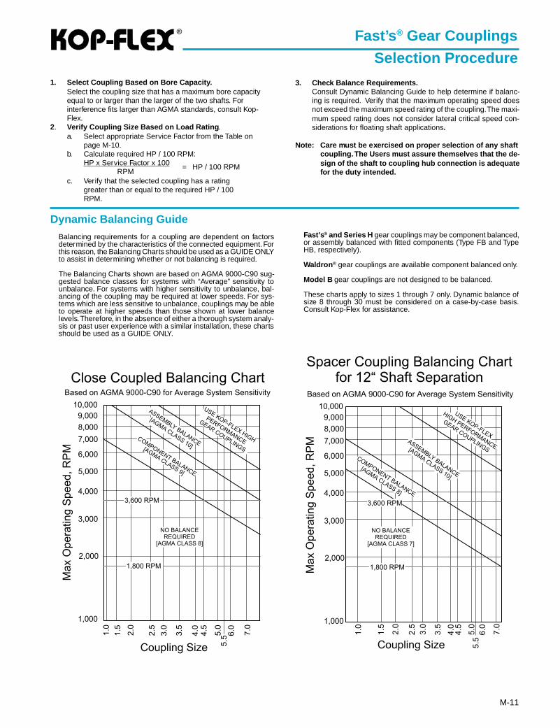
Dynamic Balancing GuideBalancing requirements for a coupling are dependent on factorsdetermined by the characteristics of the connected equipment. Forthis reason, the Balancing Charts should be used as a GUIDE ONLYto assist in determining whether or not balancing is required.
The Balancing Charts shown are based on AGMA 9000-C90 sug-gested balance classes for systems with “Average” sensitivity tounbalance. For systems with higher sensitivity to unbalance, bal-ancing of the coupling may be required at lower speeds. For sys-tems which are less sensitive to unbalance, couplings may be ableto operate at higher speeds than those shown at lower balancelevels. Therefore, in the absence of either a thorough system analy-sis or past user experience with a similar installation, these chartsshould be used as a GUIDE ONLY.
Fast’s ® Gear Couplings
Selection Procedure1. Select Coupling Based on Bore Capacity.
Select the coupling size that has a maximum bore capacityequal to or larger than the larger of the two shafts. Forinterference fits larger than AGMA standards, consult Kop-Flex.
2. Verify Coupling Size Based on Load Rating .a. Select appropriate Service Factor from the Table on
page M-10.b. Calculate required HP / 100 RPM:
HP x Service Factor x 100RPM
= HP / 100 RPM
c. Verify that the selected coupling has a ratinggreater than or equal to the required HP / 100RPM.
3. Check Balance Requirements.Consult Dynamic Balancing Guide to help determine if balanc-ing is required. Verify that the maximum operating speed doesnot exceed the maximum speed rating of the coupling. The maxi-mum speed rating does not consider lateral critical speed con-siderations for floating shaft applications.
Note: Care must be exercised on proper selection of any shaftcoupling. The Users must assure themselves that the de-sign of the shaft to coupling hub connection is adequatefor the duty intended.
Fast’s ® and Series H gear couplings may be component balanced,or assembly balanced with fitted components (Type FB and TypeHB, respectively).
Waldron ® gear couplings are available component balanced only.
Model B gear couplings are not designed to be balanced.
These charts apply to sizes 1 through 7 only. Dynamic balance ofsize 8 through 30 must be considered on a case-by-case basis.Consult Kop-Flex for assistance.
®
M-12
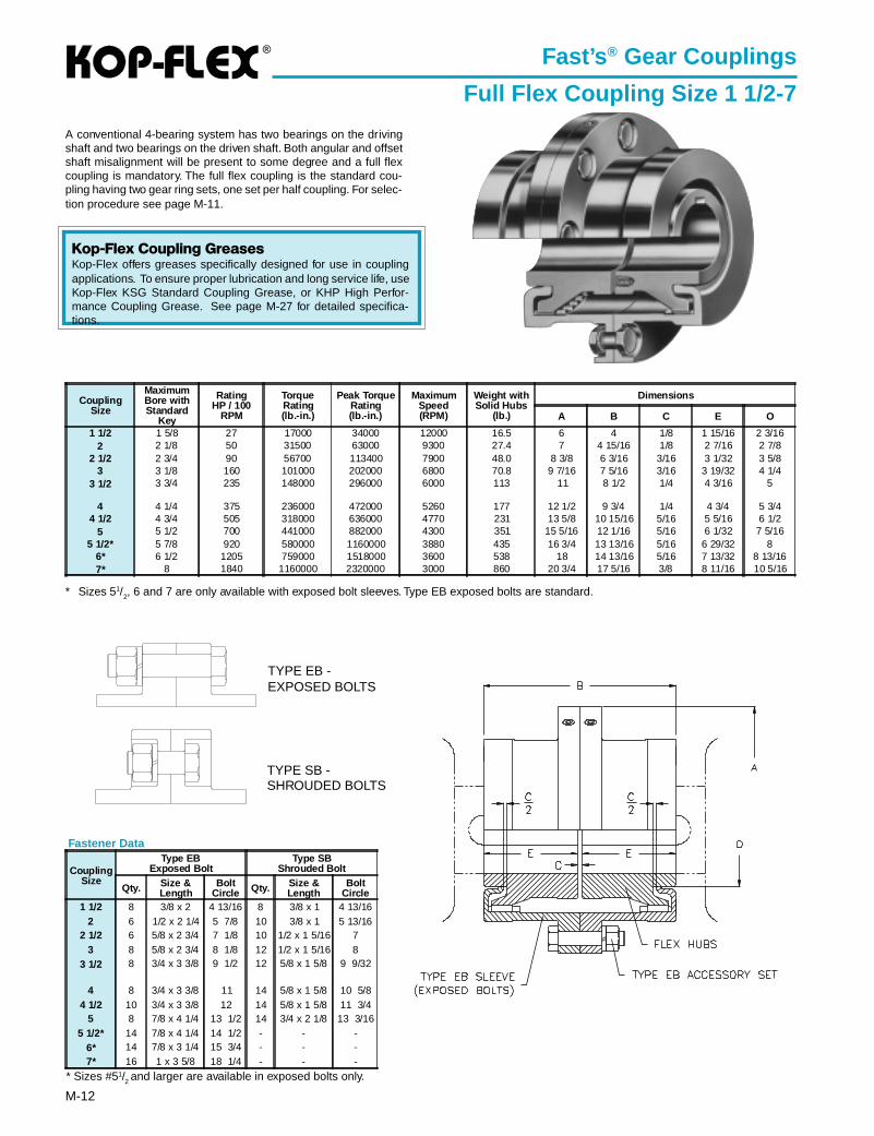
Fast’s ® Gear Couplings
Full Flex Coupling Size 1 1/2-7
A conventional 4-bearing system has two bearings on the drivingshaft and two bearings on the driven shaft. Both angular and offsetshaft misalignment will be present to some degree and a full flexcoupling is mandatory. The full flex coupling is the standard cou-pling having two gear ring sets, one set per half coupling. For selec-tion procedure see page M-11.
* Sizes 51/2, 6 and 7 are only available with exposed bolt sleeves. Type EB exposed bolts are standard.
TYPE SB -SHROUDED BOLTS
TYPE EB -EXPOSED BOLTS
CouplingSize
MaximumBore withStandard
Key
RatingHP / 100
RPM
TorqueRating(lb.-in.)
Peak TorqueRating(lb.-in.)
MaximumSpeed(RPM)
Weight withSolid Hubs
(lb.)
Dimensions
A B C E O
1 1/2 1 5/8 27 17000 34000 12000 16.5 6 4 1/8 1 15/16 2 3/162 2 1/8 50 31500 63000 9300 27.4 7 4 15/16 1/8 2 7/16 2 7/8
2 1/2 2 3/4 90 56700 113400 7900 48.0 8 3/8 6 3/16 3/16 3 1/32 3 5/83 3 1/8 160 101000 202000 6800 70.8 9 7/16 7 5/16 3/16 3 19/32 4 1/4
3 1/2 3 3/4 235 148000 296000 6000 113 11 8 1/2 1/4 4 3/16 5
4 4 1/4 375 236000 472000 5260 177 12 1/2 9 3/4 1/4 4 3/4 5 3/44 1/2 4 3/4 505 318000 636000 4770 231 13 5/8 10 15/16 5/16 5 5/16 6 1/2
5 5 1/2 700 441000 882000 4300 351 15 5/16 12 1/16 5/16 6 1/32 7 5/165 1/2* 5 7/8 920 580000 1160000 3880 435 16 3/4 13 13/16 5/16 6 29/32 8
6* 6 1/2 1205 759000 1518000 3600 538 18 14 13/16 5/16 7 13/32 8 13/167* 8 1840 1160000 2320000 3000 860 20 3/4 17 5/16 3/8 8 11/16 10 5/16
* Sizes #51/2 and larger are available in exposed bolts only.
Fastener Data
CouplingSize
Type EBExposed Bolt
Type SBShrouded Bolt
Qty. Size &Length
BoltCircle Qty. Size &
LengthBolt
Circle1 1/2 8 3/8 x 2 4 13/16 8 3/8 x 1 4 13/16
2 6 1/2 x 2 1/4 5 7/8 10 3/8 x 1 5 13/162 1/2 6 5/8 x 2 3/4 7 1/8 10 1/2 x 1 5/16 7
3 8 5/8 x 2 3/4 8 1/8 12 1/2 x 1 5/16 83 1/2 8 3/4 x 3 3/8 9 1/2 12 5/8 x 1 5/8 9 9/32
4 8 3/4 x 3 3/8 11 14 5/8 x 1 5/8 10 5/84 1/2 10 3/4 x 3 3/8 12 14 5/8 x 1 5/8 11 3/4
5 8 7/8 x 4 1/4 13 1/2 14 3/4 x 2 1/8 13 3/165 1/2* 14 7/8 x 4 1/4 14 1/2 - - -
6* 14 7/8 x 3 1/4 15 3/4 - - -7* 16 1 x 3 5/8 18 1/4 - - -
Kop-Flex Coupling GreasesKop-Flex offers greases specifically designed for use in couplingapplications. To ensure proper lubrication and long service life, useKop-Flex KSG Standard Coupling Grease, or KHP High Perfor-mance Coupling Grease. See page M-27 for detailed specifica-tions.
®
M-13
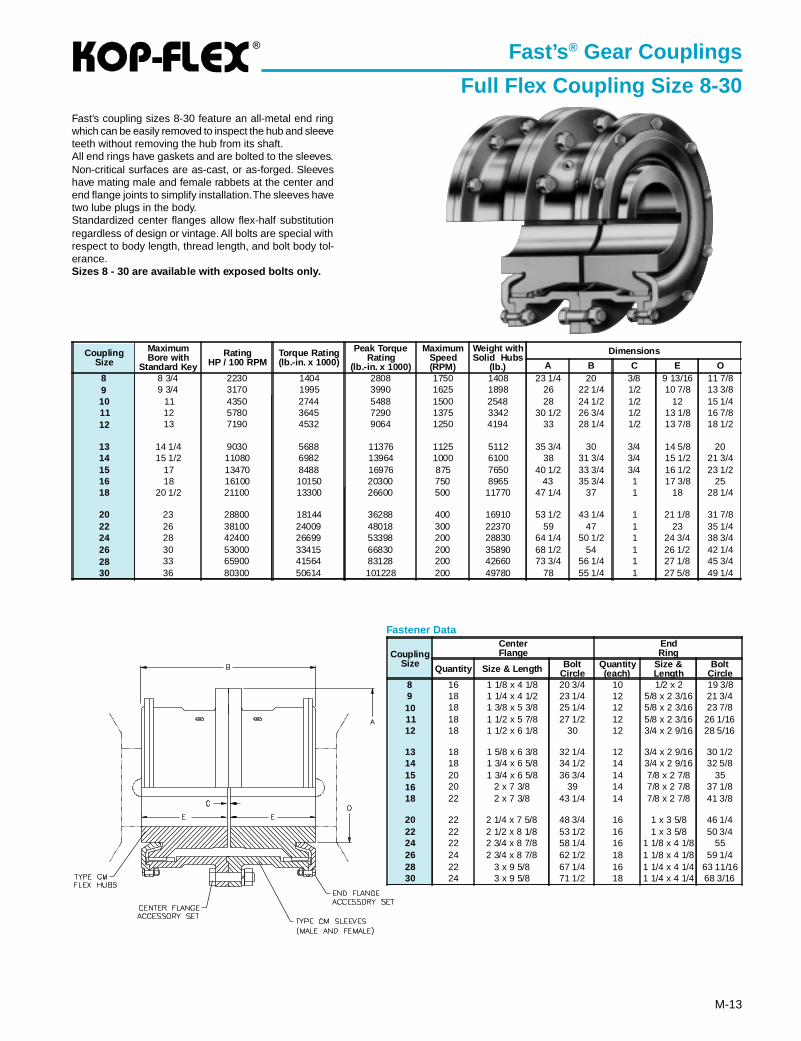
Fast’s ® Gear Couplings
Full Flex Coupling Size 8-30Fast’s coupling sizes 8-30 feature an all-metal end ringwhich can be easily removed to inspect the hub and sleeveteeth without removing the hub from its shaft.All end rings have gaskets and are bolted to the sleeves.Non-critical surfaces are as-cast, or as-forged. Sleeveshave mating male and female rabbets at the center andend flange joints to simplify installation. The sleeves havetwo lube plugs in the body.Standardized center flanges allow flex-half substitutionregardless of design or vintage. All bolts are special withrespect to body length, thread length, and bolt body tol-erance.Sizes 8 - 30 are available with exposed bolts only.
Fastener Data
CouplingSize
CenterFlange
EndRing
Quantity Size & Length BoltCircle
Quantity(each)
Size &Length
BoltCircle
8 16 1 1/8 x 4 1/8 20 3/4 10 1/2 x 2 19 3/89 18 1 1/4 x 4 1/2 23 1/4 12 5/8 x 2 3/16 21 3/410 18 1 3/8 x 5 3/8 25 1/4 12 5/8 x 2 3/16 23 7/811 18 1 1/2 x 5 7/8 27 1/2 12 5/8 x 2 3/16 26 1/1612 18 1 1/2 x 6 1/8 30 12 3/4 x 2 9/16 28 5/16
13 18 1 5/8 x 6 3/8 32 1/4 12 3/4 x 2 9/16 30 1/214 18 1 3/4 x 6 5/8 34 1/2 14 3/4 x 2 9/16 32 5/815 20 1 3/4 x 6 5/8 36 3/4 14 7/8 x 2 7/8 3516 20 2 x 7 3/8 39 14 7/8 x 2 7/8 37 1/818 22 2 x 7 3/8 43 1/4 14 7/8 x 2 7/8 41 3/8
20 22 2 1/4 x 7 5/8 48 3/4 16 1 x 3 5/8 46 1/422 22 2 1/2 x 8 1/8 53 1/2 16 1 x 3 5/8 50 3/424 22 2 3/4 x 8 7/8 58 1/4 16 1 1/8 x 4 1/8 5526 24 2 3/4 x 8 7/8 62 1/2 18 1 1/8 x 4 1/8 59 1/428 22 3 x 9 5/8 67 1/4 16 1 1/4 x 4 1/4 63 11/1630 24 3 x 9 5/8 71 1/2 18 1 1/4 x 4 1/4 68 3/16
CouplingSize
MaximumBore with
Standard Key
RatingHP / 100 RPM
Torque Rating(lb.-in. x 1000)
Peak TorqueRating
(lb.-in. x 1000)
MaximumSpeed(RPM)
Weight withSolid Hubs
(lb.)
Dimensions
A B C E O8 8 3/4 2230 1404 2808 1750 1408 23 1/4 20 3/8 9 13/16 11 7/89 9 3/4 3170 1995 3990 1625 1898 26 22 1/4 1/2 10 7/8 13 3/810 11 4350 2744 5488 1500 2548 28 24 1/2 1/2 12 15 1/411 12 5780 3645 7290 1375 3342 30 1/2 26 3/4 1/2 13 1/8 16 7/812 13 7190 4532 9064 1250 4194 33 28 1/4 1/2 13 7/8 18 1/2
13 14 1/4 9030 5688 11376 1125 5112 35 3/4 30 3/4 14 5/8 2014 15 1/2 11080 6982 13964 1000 6100 38 31 3/4 3/4 15 1/2 21 3/415 17 13470 8488 16976 875 7650 40 1/2 33 3/4 3/4 16 1/2 23 1/216 18 16100 10150 20300 750 8965 43 35 3/4 1 17 3/8 2518 20 1/2 21100 13300 26600 500 11770 47 1/4 37 1 18 28 1/4
20 23 28800 18144 36288 400 16910 53 1/2 43 1/4 1 21 1/8 31 7/822 26 38100 24009 48018 300 22370 59 47 1 23 35 1/424 28 42400 26699 53398 200 28830 64 1/4 50 1/2 1 24 3/4 38 3/426 30 53000 33415 66830 200 35890 68 1/2 54 1 26 1/2 42 1/428 33 65900 41564 83128 200 42660 73 3/4 56 1/4 1 27 1/8 45 3/430 36 80300 50614 101228 200 49780 78 55 1/4 1 27 5/8 49 1/4
®
M-14
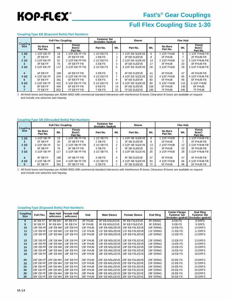
Coupling Type (Exposed Bolts) Part Numbers
Coupling Type SB (Shrouded Bolts) Part Numbers
➀ All finish bores and keyways per AGMA 9002-A86 commercial standard tolerances with interference fit bores. Clearance fit bores are available on requestand include one setscrew over keyway.
Coupling Type EB (Exposed Bolts) Part Numbers
CouplingSize
Full Flex Coupling Fastener Set(Includes Gasket) Sleeve Flex Hub
No BorePart No. Wt.
FinishBore ➀
Part No.Part No. Wt. Part No. Wt. No Bore
Part No. Wt.FinishBore ➀
Part No.1 1/2 1 1/2F SB FF 19 1 1/2F SB FF FB 1 1/2 SB FS 1 1 1/2F SB SLEEVE 6 1 1/2F FHUB 3 1 1/2F FHUB FB
2 2F SB FF 30 2F SB FF FB 2 SB FS 1 2F SB SLEEVE 8 2F FHUB 7 2F FHUB FB2 1/2 2 1/2F SB FF 52 2 1/2F SB FF FB 2 1/2 SB FS 2 2 1/2F SB SLEEVE 13 2 1/2F FHUB 12 2 1/2F FHUB FB
3 3F SB FF 76 3F SB FF FB 3 SB FS 2 3F SB SLEEVE 15 3F FHUB 20 3F FHUB FB3 1/2 3 1/2F SB FF 117 3 1/2F SB FF FB 3 1/2 SB FS 4 3 1/2F SB SLEEVE 26 3 1/2F FHUB 28 3 1/2F FHUB FB
4 4F SB FF 180 4F SB FF FB 4 SB FS 4 4F SB SLEEVE 37 4F FHUB 47 4F FHUB FB4 1/2 4 1/2F SB FF 244 4 1/2F SB FF FB 4 1/2 SB FS 4 4 1/2F SB SLEEVE 50 4 1/2F FHUB 66 4 1/2F FHUB FB
5 5F SB FF 361 5F SB FF FB 5 SB FS 7 5F SB SLEEVE 72 5F FHUB 96 5F FHUB FB
CouplingSize
Full Flex Coupling Fastener Set(Includes Gasket) Sleeve Flex Hub
No BorePart No. Wt.
FinishBore ➀
Part No.Part No. Wt. Part No. Wt. No Bore
Part No. Wt.FinishBore ➀
Part No.1 1/2 1 1/2F EB FF 19 1 1/2F EB FF FB 1 1/2 EB FS 1 1 1/2F EB SLEEVE 6 1 1/2F FHUB 3 1 1/2F FHUB FB
2 2F EB FF 30 2F EB FF FB 2 EB FS 1 2F EB SLEEVE 8 2F FHUB 7 2F FHUB FB2 1/2 2 1/2F EB FF 52 2 1/2F EB FF FB 2 1/2 EB FS 2 2 1/2F EB SLEEVE 14 2 1/2F FHUB 12 2 1/2F FHUB FB
3 3F EB FF 76 3F EB FF FB 3 EB FS 3 3F EB SLEEVE 17 3F FHUB 20 3F FHUB FB3 1/2 3 1/2F EB FF 117 3 1/2F EB FF FB 3 1/2 EB FS 5 3 1/2F EB SLEEVE 28 3 1/2F FHUB 28 3 1/2F FHUB FB
4 4F EB FF 180 4F EB FF FB 4 EB FS 5 4F EB SLEEVE 41 4F FHUB 47 4F FHUB FB4 1/2 4 1/2F EB FF 244 4 1/2F EB FF FB 4 1/2 EB FS 7 4 1/2F EB SLEEVE 53 4 1/2F FHUB 66 4 1/2F FHUB FB
5 5F EB FF 361 5F EB FF FB 5 EB FS 9 5F EB SLEEVE 80 5F FHUB 96 5F FHUB FB5 1/2 5 1/2F EB FF 422 5 1/2F EB FF FB 5 1/2 EB FS 14 5 1/2F EB SLEEVE 89 5 1/2F FHUB 115 5 1/2F FHUB
6 6F EB FF 494 6F EB FF FB 6 EB FS 14 6F EB SLEEVE 100 6F FHUB 140 6F FHUB7 7F EB FF 822 7F EB FF FB 7 EB FS 22 7F EB SLEEVE 160 7F FHUB 240 7F FHUB
Fast’s ® Gear Couplings
Full Flex Coupling Size 1-30
➀ All finish bores and keyways per AGMA 9002-A86 commercial standard tolerances with interference fit bores. Clearance fit bores are available on requestand include one setscrew over keyway.
CouplingSize Full Flex Male Half
w/AccessFemale Halfw/Access Hub Male Sleeve Female Sleeve End Ring
Center FlangeFastener Set
(includes gasket)
End RingFastener Set
(includes gasket)8 8F EB FF 8F EB MH 8F EB FH 8F FHUB 8F EB MSLEEVE 8F EB FSLEEVE 8F ERING 8 EB FS 8 ERFS9 9F EB FF 9F EB MH 9F EB FH 9F FHUB 9F EB MSLEEVE 9F EB FSLEEVE 9F ERING 9 EB FS 9 ERFS10 10F EB FF 10F EB MH 10F EB FH 10F FHUB 10F EB MSLEEVE 10F EB FSLEEVE 10F ERING 10 EB FS 10 ERFS11 11F EB FF 11F EB MH 11F EB FH 11F FHUB 11F EB MSLEEVE 11F EB FSLEEVE 11F ERING 11 EB FS 11 ERFS12 12F EB FF 12F EB MH 12F EB FH 12F FHUB 12F EB MSLEEVE 12F EB FSLEEVE 12F ERING 12 EB FS 12 ERFS
13 13F EB FF 13F EB MH 13F EB FH 13F FHUB 13F EB MSLEEVE 13F EB FSLEEVE 13F ERING 13 EB FS 13 ERFS14 14F EB FF 14F EB MH 14F EB FH 14F FHUB 14F EB MSLEEVE 14F EB FSLEEVE 14F ERING 14 EB FS 14 ERFS15 15F EB FF 15F EB MH 15F EB FH 15F FHUB 15F EB MSLEEVE 15F EB FSLEEVE 15F ERING 15 EB FS 15 ERFS16 16F EB FF 16F EB MH 16F EB FH 16F FHUB 16F EB MSLEEVE 16F EB FSLEEVE 16F ERING 16 EB FS 16 ERFS18 18F EB FF 18F EB MH 18F EB FH 18F FHUB 18F EB MSLEEVE 18F EB FSLEEVE 18F ERING 18 EB FS 18 ERFS
20 20F EB FF 20F EB MH 20F EB FH 20F FHUB 20F EB MSLEEVE 20F EB FSLEEVE 20F ERING 20 EB FS 20 ERFS22 22F EB FF 22F EB MH 22F EB FH 22F FHUB 22F EB MSLEEVE 22F EB FSLEEVE 22F ERING 22 EB FS 22 ERFS24 24F EB FF 24F EB MH 24F EB FH 24F FHUB 24F EB MSLEEVE 24F EB FSLEEVE 24F ERING 24 EB FS 24 ERFS26 26F EB FF 26F EB MH 26F EB FH 26F FHUB 26F EB MSLEEVE 26F EB FSLEEVE 26F ERING 26 EB FS 26 ERFS28 28F EB FF 28F EB MH 28F EB FH 28F FHUB 28F EB MSLEEVE 28F EB FSLEEVE 28F ERING 28 EB FS 28 ERFS30 30F EB FF 30F EB MH 30F EB FH 30F FHUB 30F EB MSLEEVE 30F EB FSLEEVE 30F ERING 30 EB FS 30 ERFS
®
M-15
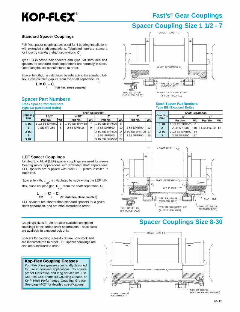
Standard Spacer Couplings
Full-flex spacer couplings are used for 4 bearing installationswith extended shaft separations. Tabulated here are spacersfor industry standard shaft separations, C
L.
Type EB exposed bolt spacers and Type SB shrouded boltspacers for standard shaft separations are normally in stock.Other lengths are manufactured to order.
Spacer length, L, is calculated by subtracting the standard full-flex, close coupled gap, C, from the shaft separation, C
L.
L = CL - C
(full-flex, close coupled)
Spacer Part NumbersStock Spacer Part NumbersType SB (Shrouded Bolts)
Stock Spacer Part NumbersType EB (Exposed Bolts)
LEF Spacer CouplingsLimited End Float (LEF) spacer couplings are used for sleevebearing motor applications with extended shaft separations.LEF spacers are supplied with steel LEF plates installed ineach end.
Spacer length, LLEF
, is calculated by subtracting the LEF full-
flex, close coupled gap, CLEF
, from the shaft separation, CL.
LLEF
= CL - C
LEF (full-flex, close coupled)
LEF spacers are shorter than standard spacers for a givenshaft separation, and are manufactured to order.
Fast’s ® Gear Couplings
Spacer Coupling Size 1 1/2 - 7
Spacer Couplings Size 8-30Couplings sizes 8 - 30 are also available as spacercouplings for extended shaft separations. These sizesare available in exposed bolt only.
Spacers for coupling sizes 4 - 30 are non-stock andare manufactured to order. LEF spacer couplings arealso manufactured to order.
CouplingSize
Shaft Separation3 1/2" 4 3/8" 5" 7"
Part No. Wt. Part No. Wt. Part No. Wt. Part No. Wt.1 1/2 1 1/2 SB SPR350 6 1 1/2 SB SPR438 7 1 1/2 SB SPR500 8
2 2 SB SPR350 8 2 SB SPR438 9 2 SB SPR500 10 2 SB SPR700 122 1/2 2 1/2 SB SPR500 14 2 1/2 SB SPR700 17
3 3 SB SPR500 17 3 SB SPR700 203 1/2 3 1/2 SB SPR500 27
CouplingSize
Shaft Separation5" 7"
Part No. Wt. Part No. Wt.1 1/2 1 1/2 EB SPR500 8
2 2 EB SPR500 10 2 EB SPR700 122 1/2 2 1/2 EB SPR500 14
3 3 EB SPR500 17
Kop-Flex Coupling GreasesKop-Flex offers greases specifically designedfor use in coupling applications. To ensureproper lubrication and long service life, useKop-Flex KSG Standard Coupling Grease, orKHP High Performance Coupling Grease.See page M-27 for detailed specifications.
L
L
SS S
LS
LEF
®
M-16
Coupling Type SB (Shrouded Bolts) Part Numbers
Coupling Type EB (Exposed Bolts) Part Numbers
➀ All finish bores and keyways per AGMA 9002-A86 commerical standard tolerances.➁ Rigid hubs are furnished less fasteners.
CouplingSize
Flex Rigid Coupling Rigid Hub ➁
No BorePart No. Wt.
FinishBore ➀
Part No.
No BorePart No. Wt.
FinishBore ➀
Part No.1 1/2 1 1/2F SB FR 19 1 1/2F SB FR FB 1 1/2 SB RHUB 9 1 1/2 SB RHUB FB
2 2F SB FR 31 2F SB FR FB 2SB RHUB 15 2SB RHUB FB2 1/2 2 1/2F SB FR 55 2 1/2F SB FR FB 2 1/2SB RHUB 27 2 1/2SB RHUB FB
3 3F SB FR 83 3F SB FR FB 3SB RHUB 40 3SB RHUB FB3 1/2 3 1/2F SB FR 126 3 1/2F SB FR FB 3 1/2SB RHUB 65 3 1/2SB RHUB FB
4 4F SB FR 184 4F SB FR FB 4SB RHUB 90 4SB RHUB FB4 1/2 4 1/2F SB FR 252 4 1/2F SB FR FB 4 1/2SB RHUB 124 4 1/2SB RHUB FB
5 5F SB FR 371 5F SB FR FB 5SB RHUB 119 5SB RHUB FB
CouplingSize
Flex Rigid Coupling Rigid Hub ➁
No BorePart No. Wt.
FinishBore ➀
Part No.
No BorePart No. Wt.
FinishBore ➀
Part No.1 1/2 1 1/2F EB FR 19 1 1/2F EB FR FB 1 1/2 EB RHUB 9 1 1/2 EB RHUB FB
2 2F EB FR 31 2F EB FR FB 2EB RHUB 15 2EB RHUB FB2 1/2 2 1/2F EB FR 55 2 1/2F EB FR FB 2 1/2EB RHUB 27 2 1/2EB RHUB FB
3 3F EB FR 83 3F EB FR FB 3SEB RHUB 40 3EB RHUB FB3 1/2 3 1/2F EB FR 126 3 1/2F EB FR FB 3 1/2EB RHUB 65 3 1/2EB RHUB FB
4 4F EB FR 184 4F EB FR FB 4EB RHUB 90 4EB RHUB FB4 1/2 4 1/2F EB FR 252 4 1/2F EB FR FB 4 1/2EB RHUB 124 4 1/2EB RHUB FB
5 5F EB FR 371 5F EB FR FB 5EB RHUB 119 5EB RHUB FB5 1/2 5 1/2F EB FR 418 5 1/2F EB FR FB 5 1/2EB RHUB 200 5 1/2EB RHUB FB
6 6F EB FR 504 6F EB FR FB 6EB RHUB 250 6EB RHUB FB7 7F EB FR 792 7F EB FR FB 7EB RHUB 370 7EB RHUB FB
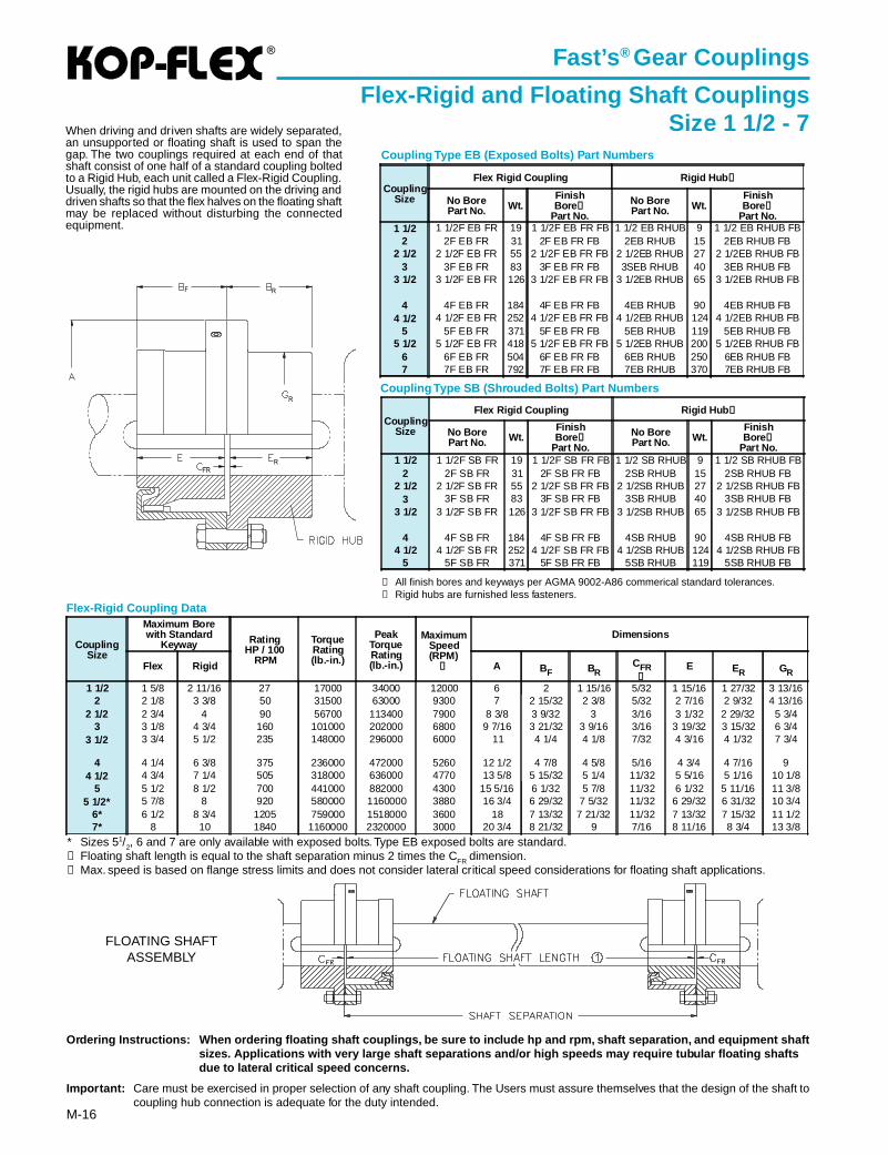
Ordering Instructions: When ordering floating shaft couplings, be sure to include hp and rpm, shaft separation, and equipment sh aftsizes. Applications with very large shaft separations and/or high speeds may require tubular floating shaftsdue to lateral critical speed concerns.
Impor tant: Care must be exercised in proper selection of any shaft coupling. The Users must assure themselves that the design of the shaft tocoupling hub connection is adequate for the duty intended.
Fast’s ® Gear Couplings
Flex-Rigid and Floating Shaft CouplingsSize 1 1/2 - 7
FLOATING SHAFTASSEMBLY
When driving and driven shafts are widely separated,an unsupported or floating shaft is used to span thegap. The two couplings required at each end of thatshaft consist of one half of a standard coupling boltedto a Rigid Hub, each unit called a Flex-Rigid Coupling.Usually, the rigid hubs are mounted on the driving anddriven shafts so that the flex halves on the floating shaftmay be replaced without disturbing the connectedequipment.
* Sizes 51/2, 6 and 7 are only available with exposed bolts. Type EB exposed bolts are standard.➀ Floating shaft length is equal to the shaft separation minus 2 times the CFR dimension.➁ Max. speed is based on flange stress limits and does not consider lateral critical speed considerations for floating shaft applications.
CouplingSize
Maximum Borewith Standard
Keyway RatingHP / 100
RPM
TorqueRating(lb.-in.)
PeakTorqueRating(lb.-in.)
MaximumSpeed(RPM)
➁
Dimensions
Flex Rigid A BF BRCFR➀
E ER GR
1 1/2 1 5/8 2 11/16 27 17000 34000 12000 6 2 1 15/16 5/32 1 15/16 1 27/32 3 13/162 2 1/8 3 3/8 50 31500 63000 9300 7 2 15/32 2 3/8 5/32 2 7/16 2 9/32 4 13/16
2 1/2 2 3/4 4 90 56700 113400 7900 8 3/8 3 9/32 3 3/16 3 1/32 2 29/32 5 3/43 3 1/8 4 3/4 160 101000 202000 6800 9 7/16 3 21/32 3 9/16 3/16 3 19/32 3 15/32 6 3/4
3 1/2 3 3/4 5 1/2 235 148000 296000 6000 11 4 1/4 4 1/8 7/32 4 3/16 4 1/32 7 3/4
4 4 1/4 6 3/8 375 236000 472000 5260 12 1/2 4 7/8 4 5/8 5/16 4 3/4 4 7/16 94 1/2 4 3/4 7 1/4 505 318000 636000 4770 13 5/8 5 15/32 5 1/4 11/32 5 5/16 5 1/16 10 1/8
5 5 1/2 8 1/2 700 441000 882000 4300 15 5/16 6 1/32 5 7/8 11/32 6 1/32 5 11/16 11 3/85 1/2* 5 7/8 8 920 580000 1160000 3880 16 3/4 6 29/32 7 5/32 11/32 6 29/32 6 31/32 10 3/4
6* 6 1/2 8 3/4 1205 759000 1518000 3600 18 7 13/32 7 21/32 11/32 7 13/32 7 15/32 11 1/27* 8 10 1840 1160000 2320000 3000 20 3/4 8 21/32 9 7/16 8 11/16 8 3/4 13 3/8
F R
R
RFR
Flex-Rigid Coupling Data
®
M-17
Fast’s ® Gear Couplings
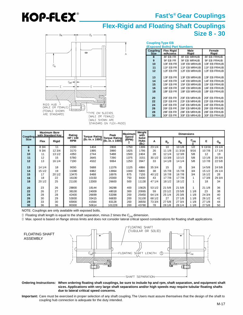
Flex-Rigid and Floating Shaft CouplingsSize 8 - 30
Coupling Type EB(Exposed Bolts) Part Numbers
FLOATING SHAFTASSEMBLY
Ordering Instructions: When ordering floating shaft couplings, be sure to include hp and rpm, shaft separation, and equipment sh aftsizes. Applications with very large shaft separations and/or high speeds may require tubular floating shaftsdue to lateral critical speed concerns.
Impor tant: Care must be exercised in proper selection of any shaft coupling. The Users must assure themselves that the design of the shaft tocoupling hub connection is adequate for the duty intended.
NOTE: Couplings are only available with exposed bolts.➀ Floating shaft length is equal to the shaft separation, minus 2 times the CFR dimension.➁ Max. speed is based on flange stress limits and does not consider lateral critical speed considerations for floating shaft applications.
CouplingSize
Flex Rigidw/Access
MaleRigid
FemaleRigid
8 8F EB FR 8F EB MRHUB 8F EB FRHUB9 9F EB FR 9F EB MRHUB 9F EB FRHUB10 10F EB FR 10F EB MRHUB 10F EB FRHUB11 11F EB FR 11F EB MRHUB 11F EB FRHUB12 12F EB FR 12F EB MRHUB 12F EB FRHUB
13 13F EB FR 13F EB MRHUB 13F EB FRHUB14 14F EB FR 14F EB MRHUB 14F EB FRHUB15 15F EB FR 15F EB MRHUB 15F EB FRHUB16 16F EB FR 16F EB MRHUB 16F EB FRHUB18 18F EB FR 18F EB MRHUB 18F EB FRHUB
20 20F EB FR 20F EB MRHUB 20F EB FRHUB22 22F EB FR 22F EB MRHUB 22F EB FRHUB24 24F EB FR 24F EB MRHUB 24F EB FRHUB26 26F EB FR 26F EB MRHUB 26F EB FRHUB28 28F EB FR 28F EB MRHUB 28F EB FRHUB30 30F EB FR 30F EB MRHUB 30F EB FRHUB
CouplingSize
Maximum Borewith Standard Key Rating
HP / 100RPM
Torque Rating(lb.-in. x 1000)
PeakTorque Rating(lb.-in. x 1000)
MaximumSpeed(RPM)
➁
WeightwithSolidHubs(lb.)
Dimensions
Flex Rigid A BF BRCFR➀
E GR
8 8 3/4 11 2230 1404 2808 1750 1306 23 1/4 10 10 1/8 1/2 9 13/16 15 1/49 9 3/4 12 3/4 3170 1995 3990 1625 1795 26 11 1/8 11 3/16 9/16 10 7/8 17 1/4
10 11 13 1/2 4350 2744 5488 1500 2404 28 12 1/4 12 3/8 5/8 12 1911 12 15 5780 3645 7290 1375 3151 30 1/2 13 3/8 13 1/2 5/8 13 1/8 20 3/412 13 16 1/4 7190 4532 9064 1250 3947 33 14 1/8 14 1/4 5/8 13 7/8 22 5/8
13 14 1/4 18 9030 5688 11376 1125 4866 35 3/4 15 15 3/4 14 5/8 24 5/814 15 1/2 19 11080 6982 13964 1000 5800 38 15 7/8 15 7/8 3/4 15 1/2 26 1/415 17 20 1/2 13470 8488 16976 875 7155 40 1/2 16 7/8 16 7/8 3/4 16 1/2 2816 18 22 16100 10150 20300 750 8430 43 17 7/8 17 7/8 1 17 3/8 29 3/418 20 1/2 25 21100 13300 26600 500 11130 47 1/4 18 1/2 18 1/2 1 18 34
20 23 26 28800 18144 36288 400 15625 53 1/2 21 5/8 21 5/8 1 21 1/8 3622 26 27 38100 24009 48018 300 20065 59 23 1/2 23 5/8 1 1/8 23 3824 28 28 42400 26699 53398 200 25450 64 1/4 25 1/4 25 3/8 1 1/8 24 3/4 4026 30 29 53000 33415 66830 200 31100 68 1/2 27 27 1/8 1 1/8 26 1/2 4228 33 30 65900 41564 83128 200 36550 73 3/4 27 5/8 27 3/4 1 1/8 27 1/8 4430 36 36 80300 50614 101228 200 43780 78 28 1/8 28 1/4 1 1/8 27 5/8 50
R F
R
FR
®
M-18
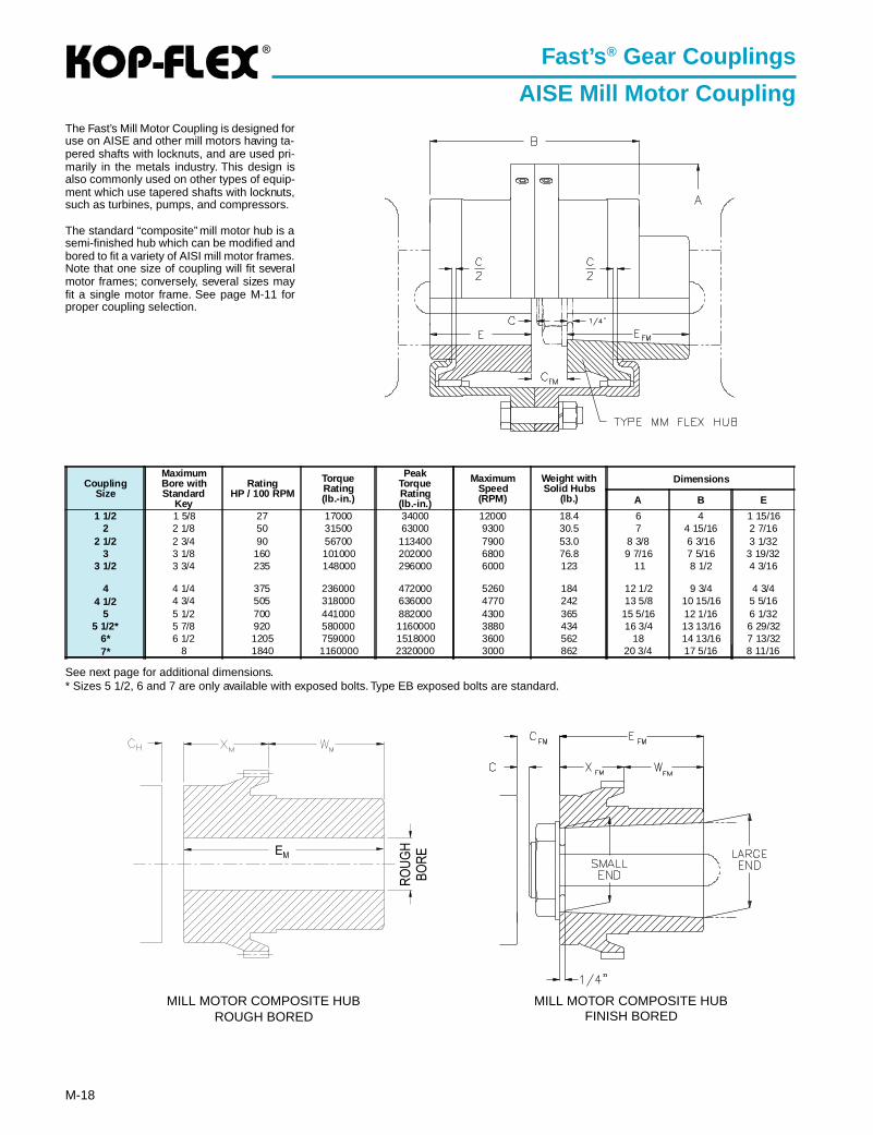
Fast’s ® Gear Couplings
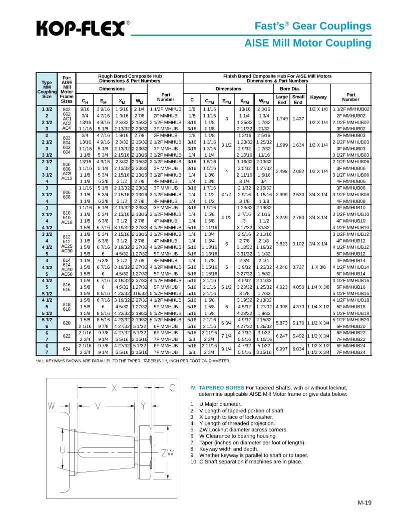
AISE Mill Motor CouplingThe Fast’s Mill Motor Coupling is designed foruse on AISE and other mill motors having ta-pered shafts with locknuts, and are used pri-marily in the metals industry. This design isalso commonly used on other types of equip-ment which use tapered shafts with locknuts,such as turbines, pumps, and compressors.
The standard “composite” mill motor hub is asemi-finished hub which can be modified andbored to fit a variety of AISI mill motor frames.Note that one size of coupling will fit severalmotor frames; conversely, several sizes mayfit a single motor frame. See page M-11 forproper coupling selection.
See next page for additional dimensions.* Sizes 5 1/2, 6 and 7 are only available with exposed bolts. Type EB exposed bolts are standard.
MILL MOTOR COMPOSITE HUBROUGH BORED
MILL MOTOR COMPOSITE HUBFINISH BORED
CouplingSize
MaximumBore withStandard
Key
RatingHP / 100 RPM
TorqueRating(lb.-in.)
PeakTorqueRating(lb.-in.)
MaximumSpeed(RPM)
Weight withSolid Hubs
(lb.)
Dimensions
A B E
1 1/2 1 5/8 27 17000 34000 12000 18.4 6 4 1 15/162 2 1/8 50 31500 63000 9300 30.5 7 4 15/16 2 7/16
2 1/2 2 3/4 90 56700 113400 7900 53.0 8 3/8 6 3/16 3 1/323 3 1/8 160 101000 202000 6800 76.8 9 7/16 7 5/16 3 19/32
3 1/2 3 3/4 235 148000 296000 6000 123 11 8 1/2 4 3/16
4 4 1/4 375 236000 472000 5260 184 12 1/2 9 3/4 4 3/44 1/2 4 3/4 505 318000 636000 4770 242 13 5/8 10 15/16 5 5/16
5 5 1/2 700 441000 882000 4300 365 15 5/16 12 1/16 6 1/325 1/2* 5 7/8 920 580000 1160000 3880 434 16 3/4 13 13/16 6 29/32
6* 6 1/2 1205 759000 1518000 3600 562 18 14 13/16 7 13/327* 8 1840 1160000 2320000 3000 862 20 3/4 17 5/16 8 11/16
M
®
M-19
Fast’s ® Gear Couplings
AISE Mill Motor Coupling
*ALL KEYWAYS SHOWN ARE PARALLEL TO THE TAPER. TAPER IS 11/4 INCH PER FOOT ON DIAMETER.
IV. TAPERED BORES For Tapered Shafts, with or without locknut,determine applicable AISE Mill Motor frame or give data below:
1. U Major diameter.2. V Length of tapered portion of shaft.3. X Length to face of lockwasher.4. Y Length of threaded projection.5. ZW Locknut diameter across corners.6. W Clearance to bearing housing.7. Taper (inches on diameter per foot of length).8. Keyway width and depth.9. Whether keyway is parallel to shaft or to taper.10. C Shaft separation if machines are in place.
TypeMM
CouplingSize
For:AISEMill
MotorFrameSizes
Rough Bored Composite HubDimensions & Part Numbers
Finish Bored Composite Hub For AISE Mill MotorsDimensions & Part Numbers
DimensionsPart
Number
Dimensions Bore Dia.
Keyway PartNumberCH EM XM WM
C CFM EFM XFM WFMLargeEnd
SmallEnd
1 1/2 802602AC1AC2AC4
9/16 3 9/16 1 5/16 2 1/4 1 1/2F MMHUB 1/8 1 1/16
3
13/16 2 3/16
1.749 1.437
1/2 X 1/8 1 1/2F MMHUB022 3/4 4 7/16 1 9/16 2 7/8 2F MMHUB 1/8 1 1/16 1 1/4 1 3/4
1/2 X 1/42F MMHUB02
2 1/2 13/16 4 9/16 2 3/32 2 15/32 2 1/2F MMHUB 3/16 1 1/8 1 25/32 1 7/32 2 1/2F MMHUB023 1 1/16 5 1/8 2 13/32 2 23/32 3F MMHUB 3/16 1 1/8 2 11/32 21/32 3F MMHUB022 803
804603604
3/4 4 7/16 1 9/16 2 7/8 2F MMHUB 1/8 1 1/8
3 1/2
1 3/16 2 5/16
1.999 1.634 1/2 X 1/4
2F MMHUB032 1/2 13/16 4 9/16 2 3/32 2 15/32 2 1/2F MMHUB 3/16 1 3/16 1 23/32 1 25/32 2 1/2F MMHUB03
3 1 1/16 5 1/8 2 13/32 2 23/32 3F MMHUB 3/16 1 3/16 2 9/32 1 7/32 3F MMHUB033 1/2 1 1/8 5 3/4 2 15/16 2 13/16 3 1/2F MMHUB 1/4 1 1/4 2 13/16 11/16 3 1/2F MMHUB032 1/2 806
606AC8
AC12
13/16 4 9/16 2 3/32 2 15/32 2 1/2F MMHUB 3/16 1 5/16
4
1 19/32 2 13/32
2.499 2.082 1/2 X 1/4
2 1/2F MMHUB063 1 1/16 5 1/8 2 13/32 2 23/32 3F MMHUB 3/16 1 5/16 2 5/32 1 27/32 3F MMHUB06
3 1/2 1 1/8 5 3/4 2 15/16 2 13/16 3 1/2F MMHUB 1/4 1 3/8 2 11/16 1 5/16 3 1/2F MMHUB064 1 1/8 6 3/8 3 1/2 2 7/8 4F MMHUB 1/4 1 3/8 3 1/4 3/4 4F MMHUB063
806608
1 1/16 5 1/8 2 13/32 2 23/32 3F MMHUB 3/16 1 7/1641/2
2 1/32 2 15/322.999 2.530 3/4 X 1/4
3F MMHUB083 1/2 1 1/8 5 3/4 2 15/16 2 13/16 3 1/2F MMHUB 1/4 1 1/2 2 9/16 1 15/16 3 1/2F MMHUB08
4 1 1/8 6 3/8 3 1/2 2 7/8 4F MMHUB 1/4 1 1/2 3 1/8 1 3/8 4F MMHUB083
810610
AC18
1 1/16 5 1/8 2 13/32 2 23/32 3F MMHUB 3/16 1 9/16
4 1/2
1 29/32 2 19/32
3.249 2.780 3/4 X 1/4
3F MMHUB10
3 1/2 1 1/8 5 3/4 2 15/16 2 13/16 3 1/2F MMHUB 1/4 1 5/8 2 7/16 2 1/16 3 1/2F MMHUB104 1 1/8 6 3/8 3 1/2 2 7/8 4F MMHUB 1/4 1 5/8 3 1 1/2 4F MMHUB10
4 1/2 1 5/8 6 7/16 3 19/32 2 27/32 4 1/2F MMHUB 5/16 1 11/16 3 17/32 31/32 4 1/2F MMHUB103 1/2 812
612AC25AC30
1 1/8 5 3/4 2 15/16 2 13/16 3 1/2F MMHUB 1/4 1 3/4
5
2 5/16 2 11/16
3.623 3.102 3/4 X 1/4
3 1/2F MMHUB124 1 1/8 6 3/8 3 1/2 2 7/8 4F MMHUB 1/4 1 3/4 2 7/8 2 1/8 4F MMHUB12
4 1/2 1 5/8 6 7/16 3 19/32 2 27/32 4 1/2F MMHUB 5/16 1 13/16 3 13/32 1 19/32 4 1/2F MMHUB125 1 5/8 6 4 5/32 1 27/32 5F MMHUB 5/16 1 13/16 3 31/32 1 1/32 5F MMHUB124 814
614AC40AC50
1 1/8 6 3/8 3 1/2 2 7/8 4F MMHUB 1/4 1 7/85
2 3/4 2 1/44.248 3.727 1 X 3/8
4F MMHUB14
4 1/2 1 5/8 6 7/16 3 19/32 2 27/32 4 1/2F MMHUB 5/16 1 15/16 3 9/32 1 23/32 4 1/2F MMHUB14
5 1 5/8 6 4 5/32 1 27/32 5F MMHUB 5/16 1 15/16 3 27/32 1 5/32 5F MMHUB144 1/2
816616
1 5/8 6 7/16 3 19/32 2 27/32 4 1/2F MMHUB 5/16 2 1/165 1/2
4 5/32 2 11/324.623 4.050 1 1/4 X 3/8
4 1/2F MMHUB165 1 5/8 6 4 5/32 1 27/32 5F MMHUB 5/16 2 1/16 3 23/32 1 25/32 5F MMHUB16
5 1/2 1 5/8 8 5/16 4 23/32 319/32 5 1/2F MMHUB 5/16 2 1/16 3 5/8 1 7/32 5 1/2F MMHUB164 1/2
818618
1 5/8 6 7/16 3 19/32 2 27/32 4 1/2F MMHUB 5/16 1 5/86
3 19/32 2 13/324.998 4.373 1 1/4 X 1/2
4 1/2F MMHUB185 1 5/8 6 4 5/32 1 27/32 5F MMHUB 5/16 1 5/8 4 5/32 1 27/32 5F MMHUB18
5 1/2 1 5/8 8 5/16 4 23/32 3 19/32 5 1/2F MMHUB 5/16 1 5/8 4 23/32 1 9/32 5 1/2F MMHUB185 1/2
6201 5/8 8 5/16 4 23/32 3 19/32 5 1/2F MMHUB 5/16 2 1/16
6 3/44 9/32 2 15/32
5.873 5.170 1 1/2 X 3/45 1/2F MMHUB20
6 2 1/16 9 7/8 4 27/32 5 1/32 6F MMHUB 5/16 2 1/16 4 27/32 1 29/32 6F MMHUB206
6222 1/16 9 7/8 4 27/32 5 1/32 6F MMHUB 5/16 2 11/16
7 1/44 7/32 3 1/32
6.247 5.492 1 1/2 X 3/46F MMHUB22
7 2 3/4 9 1/4 5 5/16 3 15/16 7F MMHUB 3/8 2 3/4 5 5/16 1 15/16 7F MMHUB226
6242 1/16 9 7/8 4 27/32 5 1/32 6F MMHUB 5/16 2 11/16
9 1/44 7/32 5 1/32
6.997 6.0341 1/2 X 1/2 6F MMHUB24
7 2 3/4 9 1/4 5 5/16 3 15/16 7F MMHUB 3/8 2 3/4 5 5/16 3 15/16 1 1/2 X 3/4 7F MMHUB24
®
M-20
Fast’s ® Gear Couplings
Limited End Float Coupling Size 1 1/2 - 7
* Sizes 51/2, 6 and 7 are only available with exposed bolts. Type EB exposed bolts arestandard.
➀ LEF Disks are used only in close coupled applications. One disk is required per coupling.Note: For ratings and max. bores refer to page M-12.
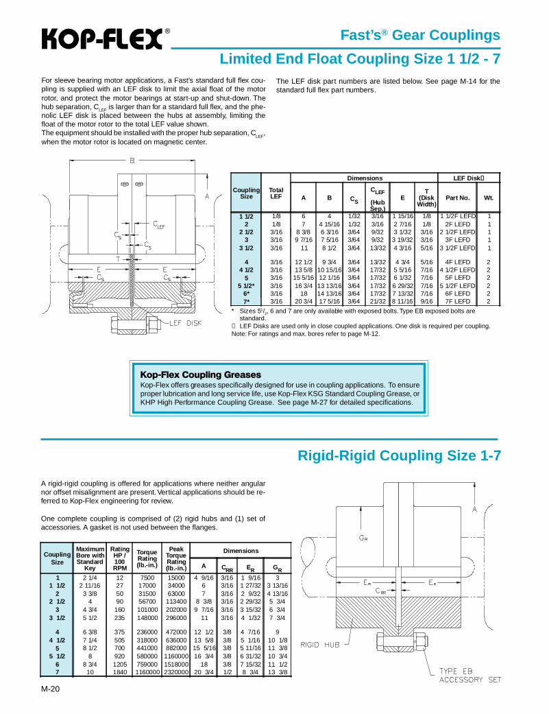
For sleeve bearing motor applications, a Fast’s standard full flex cou-pling is supplied with an LEF disk to limit the axial float of the motorrotor, and protect the motor bearings at start-up and shut-down. Thehub separation, CLEF is larger than for a standard full flex, and the phe-nolic LEF disk is placed between the hubs at assembly, limiting thefloat of the motor rotor to the total LEF value shown.The equipment should be installed with the proper hub separation, C
LEF,
when the motor rotor is located on magnetic center.
Rigid-Rigid Coupling Size 1-7
A rigid-rigid coupling is offered for applications where neither angularnor offset misalignment are present. Vertical applications should be re-ferred to Kop-Flex engineering for review.
One complete coupling is comprised of (2) rigid hubs and (1) set ofaccessories. A gasket is not used between the flanges.
CouplingSize
MaximumBore withStandard
Key
RatingHP /100RPM
TorqueRating(lb.-in.)
PeakTorqueRating(lb.-in.)
Dimensions
A CRR ER GR1 2 1/4 12 7500 15000 4 9/16 3/16 1 9/16 3
1 1/2 2 11/16 27 17000 34000 6 3/16 1 27/32 3 13/162 3 3/8 50 31500 63000 7 3/16 2 9/32 4 13/16
2 1/2 4 90 56700 113400 8 3/8 3/16 2 29/32 5 3/43 4 3/4 160 101000 202000 9 7/16 3/16 3 15/32 6 3/4
3 1/2 5 1/2 235 148000 296000 11 3/16 4 1/32 7 3/4
4 6 3/8 375 236000 472000 12 1/2 3/8 4 7/16 94 1/2 7 1/4 505 318000 636000 13 5/8 3/8 5 1/16 10 1/8
5 8 1/2 700 441000 882000 15 5/16 3/8 5 11/16 11 3/85 1/2 8 920 580000 1160000 16 3/4 3/8 6 31/32 10 3/4
6 8 3/4 1205 759000 1518000 18 3/8 7 15/32 11 1/27 10 1840 1160000 2320000 20 3/4 1/2 8 3/4 13 3/8
Kop-Flex Coupling GreasesKop-Flex offers greases specifically designed for use in coupling applications. To ensureproper lubrication and long service life, use Kop-Flex KSG Standard Coupling Grease, orKHP High Performance Coupling Grease. See page M-27 for detailed specifications.
CouplingSize
TotalLEF
Dimensions LEF Disk ➀
A B CS
CLEF
(HubSep.)
ET
(DiskWidth)
Part No. Wt.
1 1/2 1/8 6 4 1/32 3/16 1 15/16 1/8 1 1/2F LEFD 12 1/8 7 4 15/16 1/32 3/16 2 7/16 1/8 2F LEFD 1
2 1/2 3/16 8 3/8 6 3/16 3/64 9/32 3 1/32 3/16 2 1/2F LEFD 13 3/16 9 7/16 7 5/16 3/64 9/32 3 19/32 3/16 3F LEFD 1
3 1/2 3/16 11 8 1/2 3/64 13/32 4 3/16 5/16 3 1/2F LEFD 1
4 3/16 12 1/2 9 3/4 3/64 13/32 4 3/4 5/16 4F LEFD 24 1/2 3/16 13 5/8 10 15/16 3/64 17/32 5 5/16 7/16 4 1/2F LEFD 2
5 3/16 15 5/16 12 1/16 3/64 17/32 6 1/32 7/16 5F LEFD 25 1/2* 3/16 16 3/4 13 13/16 3/64 17/32 6 29/32 7/16 5 1/2F LEFD 2
6* 3/16 18 14 13/16 3/64 17/32 7 13/32 7/16 6F LEFD 27* 3/16 20 3/4 17 5/16 3/64 21/32 8 11/16 9/16 7F LEFD 2
The LEF disk part numbers are listed below. See page M-14 for thestandard full flex part numbers.

®
M-21
Fast’s ® Gear Couplings
Short Slide Coupling
* Exposed bolts are standard for all sizes.➀ Values are based on using Type SS flex hubs in a full-flex coupling and Type SR flex hub in a flex-rigid assembly. For each Type SR flex hub substituted in a full-
flex unit, total slide and C maximum are reduced by the amount of (ESR-ESS). Substitution of a Type SS flex hub in a flex-rigid coupling increases CFR maximum and
CFR minimum by the amount of (ESR-ESS), but total slide cannot be increased without derating the coupling.
Note: For ratings, max. bores and additional dimensions, see page M-16.
The Fast’s Short Slide coupling is designed for drive systems that require greaterend float or slide than a conventional application, providing two to three timesthe slide of a standard coupling. The coupling uses standard EB sleeves withflex hubs modified for more end float, along with a stop plate designed to maxi-mize the total slide by equalizing the slide in each half. Spacer couplings, float-ing shaft arrangements, and most coupling types can be supplied with a ShortSlide flex half in one or both flex half couplings.
FLOATING SHAFT ASSEMBLY
CouplingSize
Full Flex Coupling Stop Plate Fastener Set(Includes Gasket)
Short Slide Flex Hub(Full Flex)
Short Slide Flex Hub(Flex Rigid)
No BorePart No. Wt.
FinishBore ➀
Part No.Part No. Wt. Part No. Wt. No Bore
Part No. Wt. No BorePart No. Wt.
1 1/2 1 1/2F EB SSFF 18 1 1/2F EB SSFF FB 1 1/2 EB SP 1 1 1/2 EB VSFS 1 1 1/2F SSHUB 3 1 1/2F SRHUB 32 2F EB SSFF 28 2F EB SSFF FB 2 EB SP 2 2 EB VSFS 1 2F SSHUB 6 2F SRHUB 6
2 1/2 2 1/2F EB SSFF 50 2 1/2F EB SSFF FB 2 1/2 EB SP 2 2 1/2 EB VSFS 2 2 1/2F SSHUB 11 2 1/2F SRHUB 113 3F EB SSFF 74 3F EB SSFF FB 3 EB SP 3 3 EB VSFS 3 3F SSHUB 18 3F SRHUB 18
3 1/2 3 1/2F EB SSFF 110 3 1/2F EB SSFF FB 3 1/2 EB SP 4 3 1/2 EB VSFS 5 3 1/2F SSHUB 26 3 1/2F SRHUB 26
4 4F EB SSFF 170 4F EB SSFF FB 4 EB SP 7 4 EB VSFS 5 4F SSHUB 44 4F SRHUB 444 1/2 4 1/2F EB SSFF 230 4 1/2F EB SSFF FB 4 1/2 EB SP 10 4 1/2 EB VSFS 7 4 1/2F SSHUB 62 4 1/2F SRHUB 62
5 5F EB SSFF 350 5F EB SSFF FB 5 EB SP 12 5 EB VSFS 9 5F SSHUB 90 5F SRHUB 905 1/2 5 1/2F EB SSFF 400 5 1/2F EB SSFF FB 5 1/2 EB SP 15 5 1/2 EB VSFS 14 5 1/2F SSHUB 105 5 1/2F SRHUB 105
6 6F EB SSFF 470 6F EB SSFF FB 6 EB SP 19 6 EB VSFS 14 6F SSHUB 130 6F SRHUB 1307 7F EB SSFF 790 7F EB SSFF FB 7 EB SP 25 7 EB VSFS 22 7F SSHUB 210 7F SRHUB 210
* Exposed bolts are standard for all sizes. Shrouded bolts are available through size 5.➀ All finish bores and keyways per AGMA 9002-A86 commercial standard tolerances with interference fit bores. Clearance fit bores are available on request and
include one setscrew over keyway.Note: For finish bored flex hubs, add FB and the bore size.
CouplingSize*
Total Slide ➀ Dimensions
Full-Flex Flex-Rigid A BF BR
CSS➀
Hub & ShaftSeparation
CSR➀
Hub & ShaftSeparation
ESS ESRT O
Max. Min. Max. Min.1 1/2 7/16 3/16 6 2 1 15/16 19/32 5/32 13/64 1/64 1 13/16 1 15/16 1/8 2 3/16
2 9/16 9/32 7 2 15/32 2 3/8 23/32 5/32 19/64 1/64 2 1/4 2 11/32 1/8 2 7/82 1/2 3/4 3/8 8 3/8 3 9/32 3 29/32 5/32 25/64 1/64 2 13/16 2 29/32 1/8 3 5/8
3 7/8 7/16 9 7/16 3 21/32 3 9/16 1 1/32 5/32 29/64 1/64 3 5/16 3 13/32 1/8 4 1/43 1/2 1 1/2 11 4 1/4 4 1/8 1 1/4 1/4 17/32 1/32 3 7/8 3 31/32 3/16 5
4 1 1/8 9/16 12 1/2 4 7/8 4 5/8 1 3/8 1/4 19/32 1/32 4 3/8 4 9/16 3/16 5 3/44 1/2 1 5/16 21/32 13 5/8 5 15/32 5 1/4 1 9/16 1/4 11/16 1/32 4 29/32 5 3/32 3/16 6 1/2
5 1 7/16 23/32 15 5/16 6 1/32 5 7/8 1 11/16 1/4 3/4 1/32 5 9/16 5 3/4 3/16 7 5/165 1/2 1 7/16 23/32 16 3/4 6 29/32 7 5/32 1 3/4 5/16 3/4 1/32 6 7/16 6 11/16 1/4 8
6 1 3/8 11/16 18 7 13/32 7 21/32 1 23/32 11/32 47/64 3/64 6 15/16 7 3/16 1/4 8 13/167 2 9/16 1 9/32 20 3/4 8 21/32 9 2 31/32 13/32 1 21/64 3/64 7 11/16 8 5/16 10 5/16
R
SRSR
R
VSFS
®
M-22
Fast’s ® Gear Couplings
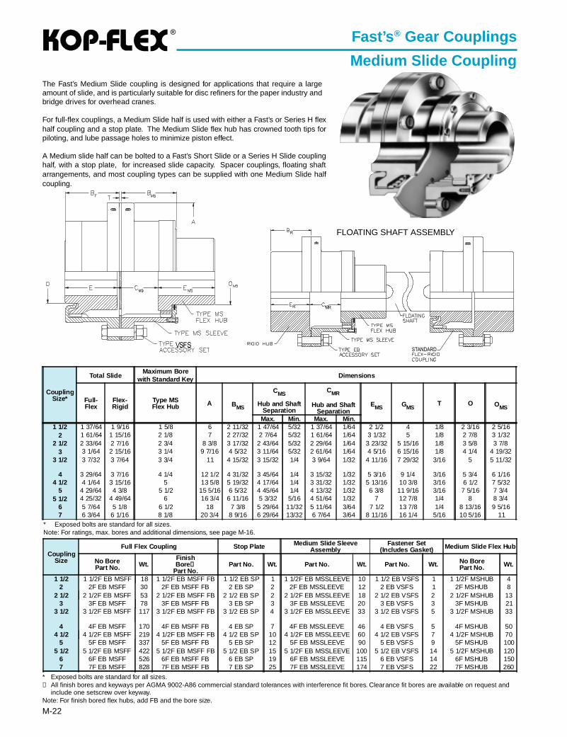
Medium Slide CouplingThe Fast’s Medium Slide coupling is designed for applications that require a largeamount of slide, and is particularly suitable for disc refiners for the paper industry andbridge drives for overhead cranes.
For full-flex couplings, a Medium Slide half is used with either a Fast’s or Series H flexhalf coupling and a stop plate. The Medium Slide flex hub has crowned tooth tips forpiloting, and lube passage holes to minimize piston effect.
A Medium slide half can be bolted to a Fast’s Short Slide or a Series H Slide couplinghalf, with a stop plate, for increased slide capacity. Spacer couplings, floating shaftarrangements, and most coupling types can be supplied with one Medium Slide halfcoupling.
* Exposed bolts are standard for all sizes.Note: For ratings, max. bores and additional dimensions, see page M-16.
VSFS
FLOATING SHAFT ASSEMBLY
CouplingSize*
Total SlideMaximum Bore
with Standard Key Dimensions
Full-Flex
Flex-Rigid
Type MSFlex Hub A BMS
CMS
Hub and ShaftSeparation
CMR
Hub and ShaftSeparation
EMS GMST O OMS
Max. Min. Max. Min.1 1/2 1 37/64 1 9/16 1 5/8 6 2 11/32 1 47/64 5/32 1 37/64 1/64 2 1/2 4 1/8 2 3/16 2 5/16
2 1 61/64 1 15/16 2 1/8 7 2 27/32 2 7/64 5/32 1 61/64 1/64 3 1/32 5 1/8 2 7/8 3 1/322 1/2 2 33/64 2 7/16 2 3/4 8 3/8 3 17/32 2 43/64 5/32 2 29/64 1/64 3 23/32 5 15/16 1/8 3 5/8 3 7/8
3 3 1/64 2 15/16 3 1/4 9 7/16 4 5/32 3 11/64 5/32 2 61/64 1/64 4 5/16 6 15/16 1/8 4 1/4 4 19/323 1/2 3 7/32 3 7/64 3 3/4 11 4 15/32 3 15/32 1/4 3 9/64 1/32 4 11/16 7 29/32 3/16 5 5 11/32
4 3 29/64 3 7/16 4 1/4 12 1/2 4 31/32 3 45/64 1/4 3 15/32 1/32 5 3/16 9 1/4 3/16 5 3/4 6 1/164 1/2 4 1/64 3 15/16 5 13 5/8 5 19/32 4 17/64 1/4 3 31/32 1/32 5 13/16 10 3/8 3/16 6 1/2 7 5/32
5 4 29/64 4 3/8 5 1/2 15 5/16 6 5/32 4 45/64 1/4 4 13/32 1/32 6 3/8 11 9/16 3/16 7 5/16 7 3/45 1/2 4 25/32 4 49/64 6 16 3/4 6 11/16 5 3/32 5/16 4 51/64 1/32 7 12 7/8 1/4 8 8 3/4
6 5 7/64 5 1/8 6 1/2 18 7 3/8 5 29/64 11/32 5 11/64 3/64 7 1/2 13 7/8 1/4 8 13/16 9 5/167 6 3/64 6 1/16 8 1/8 20 3/4 8 9/16 6 29/64 13/32 6 7/64 3/64 8 11/16 16 1/4 5/16 10 5/16 11
CouplingSize
Full Flex Coupling Stop Plate Medium Slide SleeveAssembly
Fastener Set(Includes Gasket) Medium Slide Flex Hub
No BorePart No. Wt.
FinishBore ➀
Part No.Part No. Wt. Part No. Wt. Part No. Wt. No Bore
Part No. Wt.
1 1/2 1 1/2F EB MSFF 18 1 1/2F EB MSFF FB 1 1/2 EB SP 1 1 1/2F EB MSSLEEVE 10 1 1/2 EB VSFS 1 1 1/2F MSHUB 42 2F EB MSFF 30 2F EB MSFF FB 2 EB SP 2 2F EB MSSLEEVE 12 2 EB VSFS 1 2F MSHUB 8
2 1/2 2 1/2F EB MSFF 53 2 1/2F EB MSFF FB 2 1/2 EB SP 2 2 1/2F EB MSSLEEVE 18 2 1/2 EB VSFS 2 2 1/2F MSHUB 133 3F EB MSFF 78 3F EB MSFF FB 3 EB SP 3 3F EB MSSLEEVE 20 3 EB VSFS 3 3F MSHUB 21
3 1/2 3 1/2F EB MSFF 117 3 1/2F EB MSFF FB 3 1/2 EB SP 4 3 1/2F EB MSSLEEVE 33 3 1/2 EB VSFS 5 3 1/2F MSHUB 33
4 4F EB MSFF 170 4F EB MSFF FB 4 EB SP 7 4F EB MSSLEEVE 46 4 EB VSFS 5 4F MSHUB 504 1/2 4 1/2F EB MSFF 219 4 1/2F EB MSFF FB 4 1/2 EB SP 10 4 1/2F EB MSSLEEVE 60 4 1/2 EB VSFS 7 4 1/2F MSHUB 70
5 5F EB MSFF 337 5F EB MSFF FB 5 EB SP 12 5F EB MSSLEEVE 90 5 EB VSFS 9 5F MSHUB 1005 1/2 5 1/2F EB MSFF 422 5 1/2F EB MSFF FB 5 1/2 EB SP 15 5 1/2F EB MSSLEEVE 100 5 1/2 EB VSFS 14 5 1/2F MSHUB 120
6 6F EB MSFF 526 6F EB MSFF FB 6 EB SP 19 6F EB MSSLEEVE 115 6 EB VSFS 14 6F MSHUB 1507 7F EB MSFF 828 7F EB MSFF FB 7 EB SP 25 7F EB MSSLEEVE 174 7 EB VSFS 22 7F MSHUB 260
* Exposed bolts are standard for all sizes.➀ All finish bores and keyways per AGMA 9002-A86 commercial standard tolerances with interference fit bores. Clearance fit bores are available on request and
include one setscrew over keyway.Note: For finish bored flex hubs, add FB and the bore size.
R
R MR
®
M-23
Fast’s ® Gear Couplings
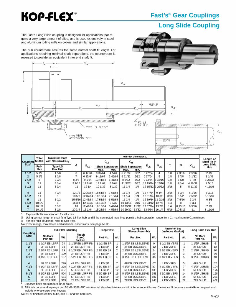
Long Slide CouplingThe Fast’s Long Slide coupling is designed for applications that re-quire a very large amount of slide, and is used extensively in steeland aluminum rolling mills on coilers and similar applications.
The hub counterbore assures the same normal shaft fit length. Forapplications requiring minimal shaft separations, the counterbore isreversed to provide an equivalent inner end shaft fit.
* Exposed bolts are standard for all sizes.➀ Using correct length of shaft fit in Type LS flex hub, and if the connected machines permit a hub separation range from CH maximum to CH minimum.➁ For flex-rigid couplings, refer to Kop-Flex.Note: For ratings, max. bores and additional dimensions, see page M-12.
CouplingSize
Full Flex Coupling Stop Plate Long SlideSleeve Assembly
Fastener Set(Includes Gasket) Long Slide Flex Hub
No BorePart No. Wt.
FinishBore ➀
Part No.Part No. Wt. Part No. Wt. Part No. Wt. No Bore
Part No. Wt.
1 1/2 1 1/2F EB LSFF 24 1 1/2F EB LSFF FB 1 1/2 EB SP 1 1 1/2F EB LSSLEEVE 9 1 1/2 EB VSFS 1 1 1/2F LSHUB 62 2F EB LSFF 38 2F EB LSFF FB 2 EB SP 2 2F EB LSSLEEVE 12 2 EB VSFS 1 2F LSHUB 12
2 1/2 2 1/2F EB LSFF 69 2 1/2F EB LSFF FB 2 1/2 EB SP 2 2 1/2F EB LSSLEEVE 24 2 1/2 EB VSFS 2 2 1/2F LSHUB 203 3F EB LSFF 109 3F EB LSFF FB 3 EB SP 3 3F EB LSSLEEVE 29 3 EB VSFS 3 3F LSHUB 36
3 1/2 3 1/2F EB LSFF 157 3 1/2F EB LSFF FB 3 1/2 EB SP 4 3 1/2F EB LSSLEEVE 46 3 1/2 EB VSFS 5 3 1/2F LSHUB 40
4 4F EB LSFF 220 4F EB LSFF FB 4 EB SP 7 4F EB LSSLEEVE 62 4 EB VSFS 5 4F LSHUB 824 1/2 4 1/2F EB LSFF 278 4 1/2F EB LSFF FB 4 1/2 EB SP 10 4 1/2F EB LSSLEEVE 87 4 1/2 EB VSFS 7 4 1/2F LSHUB 104
5 5F EB LSFF 407 5F EB LSFF FB 5 EB SP 12 5F EB LSSLEEVE 138 5 EB VSFS 9 5F LSHUB 1755 1/2 5 1/2F EB LSFF 504 5 1/2F EB LSFF FB 5 1/2 EB SP 15 5 1/2F EB LSSLEEVE 158 5 1/2 EB VSFS 14 5 1/2F LSHUB 198
6 6F EB LSFF 611 6F EB LSFF FB 6 EB SP 19 6F EB LSSLEEVE 187 6 EB VSFS 14 6F LSHUB 2567 7F EB LSFF 913 7F EB LSFF FB 7 EB SP 25 7F EB LSSLEEVE 243 7 EB VSFS 22 7F LSHUB 402
* Exposed bolts are standard for all sizes.➀ All finish bores and keyways per AGMA 9002-A86 commercial standard tolerances with interference fit bores. Clearance fit bores are available on request and
include one setscrew over keyway.Note: For finish bored flex hubs, add FB and the bore size.
LS
LS
CouplingSize*
TotalSlide➀
Maximum Borewith Standard Key
Full-Flex Dimensions ➁Length of
Shaft Fit inLong Slide
HubA BLS
CLS
Shaft Separation
CH
Shaft Separation ELS GLST O OLSFull-
FlexType LSFlex Hub Max. Min. Max. Min.
1 1/2 5 1/2 1 5/8 6 6 17/64 9 37/64 4 5/64 5 21/32 5/32 6 27/64 4 1/8 2 3/16 2 5/16 2 1/22 5 1/2 2 1/8 7 6 25/64 9 13/64 3 45/64 5 21/32 5/32 6 37/64 5 1/8 2 7/8 3 1/32 3 1/32
2 1/2 8 2 3/4 8 3/8 9 1/64 13 41/64 5 41/64 8 5/32 5/32 9 13/64 5 15/16 1/8 3 5/8 3 7/8 3 23/323 11 3 1/4 9 7/16 12 9/64 19 9/64 8 9/64 11 5/32 5/32 12 19/64 6 15/16 1/8 4 1/4 4 19/32 4 5/16
3 1/2 11 3 3/4 11 12 1/4 19 1/32 8 1/32 11 1/4 1/4 12 15/32 7 29/32 3/16 5 5 11/32 4 11/16
4 11 4 1/4 12 1/2 12 33/64 18 51/64 7 51/64 11 1/4 1/4 12 47/64 9 1/4 3/16 5 3/4 6 1/16 5 3/164 1/2 11 5 13 5/8 12 37/64 18 15/64 7 15/64 11 1/4 1/4 12 51/64 10 3/8 3/16 6 1/2 7 5/32 5 13/16
5 11 5 1/2 15 5/16 12 45/64 17 51/64 6 51/64 11 1/4 1/4 12 59/64 11 9/16 3/16 7 5/16 7 3/4 6 3/85 1/2 10 1/2 6 16 3/4 12 13/32 16 17/32 6 1/32 10 13/16 5/16 12 23/32 12 7/8 1/4 8 8 3/4 7
6 10 1/2 6 1/2 18 12 49/64 16 15/64 5 47/64 10 29/32 11/32 12 57/64 13 7/8 1/4 8 13/16 9 5/16 7 1/27 10 1/2 8 1/8 20 3/4 13 1/64 15 23/64 4 55/64 10 29/32 13/32 13 9/64 16 1/4 5/16 10 5/16 11 8 11/16
®
M-24
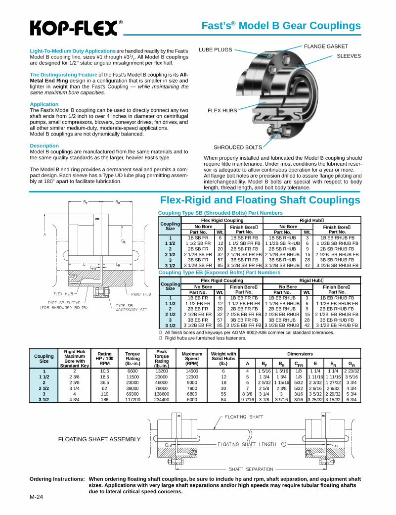
Fast’s ® Model B Gear Couplings
Light-To-Medium Duty Applications are handled readily by the Fast’sModel B coupling line, sizes #1 through #31/2. All Model B couplingsare designed for 1/2° static angular misalignment per flex half.
The Distinguishing Feature of the Fast’s Model B coupling is its All-Metal End Ring design in a configuration that is smaller in size andlighter in weight than the Fast’s Coupling — while maintaining thesame maximum bore capacities.
ApplicationThe Fast’s Model B coupling can be used to directly connect any twoshaft ends from 1/2 inch to over 4 inches in diameter on centrifugalpumps, small compressors, blowers, conveyor drives, fan drives, andall other similar medium-duty, moderate-speed applications.Model B couplings are not dynamically balanced.
DescriptionModel B couplings are manufactured from the same materials and tothe same quality standards as the larger, heavier Fast’s type.
The Model B end ring provides a permanent seal and permits a com-pact design. Each sleeve has a Type UD lube plug permitting assem-bly at 180° apart to facilitate lubrication.
When properly installed and lubricated the Model B coupling shouldrequire little maintenance. Under most conditions the lubricant reser-voir is adequate to allow continuous operation for a year or more.All flange bolt holes are precision drilled to assure flange piloting andinterchangeability. Model B bolts are special with respect to bodylength, thread length, and bolt body tolerance.
Flex-Rigid and Floating Shaft Couplings
Ordering Instructions: When ordering floating shaft couplings, be sure to include hp and rpm, shaft separation, and equipment sh aftsizes. Applications with very large shaft separations and/or high speeds may require tubular floating shaftsdue to lateral critical speed concerns.
Coupling Type SB (Shrouded Bolts) Part Numbers
Coupling Type EB (Exposed Bolts) Part Numbers
FLOATING SHAFT ASSEMBLY
➀ All finish bores and keyways per AGMA 9002-A86 commerical standard tolerances.➁ Rigid hubs are furnished less fasteners.
CouplingSize
Flex Rigid Coupling Rigid Hub ➁
No Bore Finish Bore ➀Part No.
No Bore Finish Bore ➀Part No.Part No. Wt. Part No. Wt.
1 1B SB FR 6 1B SB FR FB 1B SB RHUB 3 1B SB RHUB FB1 1/2 1 1/2 SB FR 12 1 1/2 SB FR FB 1 1/2B SB RHUB 6 1 1/2B SB RHUB FB
2 2B SB FR 20 2B SB FR FB 2B SB RHUB 9 2B SB RHUB FB2 1/2 2 1/2B SB FR 32 2 1/2B SB FR FB 2 1/2B SB RHUB 15 2 1/2B SB RHUB FB
3 3B SB FR 57 3B SB FR FB 3B SB RHUB 28 3B SB RHUB FB3 1/2 3 1/2B SB FR 85 3 1/2B SB FR FB 3 1/2B SB RHUB 42 3 1/2B SB RHUB FB
CouplingSize
Flex Rigid Coupling Rigid Hub ➁
No Bore Finish Bore ➀Part No.
No Bore Finish Bore ➀Part No.Part No. Wt. Part No. Wt.
1 1B EB FR 6 1B EB FR FB 1B EB RHUB 3 1B EB RHUB FB1 1/2 1 1/2 EB FR 12 1 1/2 EB FR FB 1 1/2B EB RHUB 6 1 1/2B EB RHUB FB
2 2B EB FR 20 2B EB FR FB 2B EB RHUB 9 2B EB RHUB FB2 1/2 2 1/2B EB FR 32 2 1/2B EB FR FB 2 1/2B EB RHUB 15 2 1/2B EB RHUB FB
3 3B EB FR 57 3B EB FR FB 3B EB RHUB 28 3B EB RHUB FB3 1/2 3 1/2B EB FR 85 3 1/2B EB FR FB 3 1/2B EB RHUB 42 3 1/2B EB RHUB FB
CouplingSize
Rigid HubMaximumBore with
Standard Key
RatingHP / 100
RPM
TorqueRating(lb.-in.)
PeakTorqueRating(lb.-in.)
MaximumSpeed(RPM)
Weight withSolid Hubs
(lb.)
Dimensions
A BF BR CFR E ER GR
1 2 10.5 6600 13200 14500 6 4 1 5/16 1 5/16 1/8 1 1/4 1 1/4 2 23/321 1/2 2 3/8 18.5 11500 23000 12000 12 5 1 3/4 1 3/4 1/8 1 11/16 1 11/16 3 5/16
2 2 5/8 36.5 23000 46000 9300 18 6 2 5/32 1 15/16 5/32 2 3/32 1 27/32 3 3/42 1/2 3 1/4 62 39000 78000 7900 30 7 2 5/8 2 3/8 5/32 2 9/16 2 9/32 4 3/4
3 4 110 69300 138600 6800 55 8 3/8 3 1/4 3 3/16 3 5/32 2 29/32 5 3/43 1/2 4 3/4 186 117200 234400 6000 84 9 7/16 3 7/8 3 9/16 3/16 3 25/32 3 15/32 6 3/4
F R
R
RFR
SLEEVES
FLANGE GASKETLUBE PLUGS
FLEX HUBS
SHROUDED BOLTS

®
M-25
Fast’s ® Model B Gear Couplings
Full Flex Coupling
Coupling Type SB (Shrouded Bolts) Part Numbers
Coupling Type EB (Exposed Bolts) Part Numbers
➀ All finish bores and keyways per AGMA 9002-A86 commerical standard tolerances. Each Clearance bore includes one set screw over keyway.
Impor tant: Care must be exercised in proper selection of any shaft coupling. The Users must assure themselves that the design of the shaft tocoupling hub connection is adequate for the duty intended.
CouplingSize
Maximum Borewith
Standard Key
RatingHP / 100 RPM
TorqueRating(lb.-in.)
PeakTorqueRating(lb.-in.)
MaximumSpeedRPM
WeightwithSolidHubs(lb.)
Dimensions Shrouded Bolt*and Exposed Bolt
A B C E O BoltCircle
Number &Size.
1 1 1/8 10.5 6600 13200 14500 5.5 4 2 5/8 1/8 1 1/4 1 9/16 3 5/16 6 — 1/41 1/2 1 5/8 18.5 11500 23000 12000 11 5 3 1/2 1/8 1 11/16 2 3/16 4 3/32 6 — 5/16
2 2 1/8 36.5 23000 46000 9300 19 6 4 5/16 1/8 2 3/32 2 7/8 5 6 — 3/82 1/2 2 3/4 62 39000 78000 7900 31 7 5 1/4 1/8 2 9/16 3 11/16 6 6 — 3/8
3 3 1/8 110 69300 138600 6800 57 8 3/8 6 1/2 3/16 3 5/32 4 1/4 7 3/16 8 — 1/23 1/2 3 3/4 186 117200 234400 6000 81 9 7/16 7 3/4 3/16 3 25/32 5 8 1/4 10 — 1/2
CouplingSize
Full Flex Coupling Fastener Set(IncludesGasket) Sleeve Flex Hub
No BorePart No. Wt.
FinishBore ➀
Part No.Part No. Wt. Part No. Wt. No Bore
Part No. Wt.FinishBore ➀
Part No.1 1B SB FF 7 1B SB FF FB 1B SB FS 1 1B SB SLEEVE 2 1B FHUB 1 1B FHUB FB
1 1/2 1 1/2B SB FF 12 1 1/2B SB FF FB 1 1/2B SB FS 1 1 1/2B SB SLEEVE 3 1 1/2B FHUB 3 1 1/2B FHUB FB2 2B SB FF 21 2B SB FF FB 2B SB FS 1 2B SB SLEEVE 5 2B FHUB 5 2B FHUB FB
2 1/2 2 1/2B SB FF 33 2 1/2B SB FF FB 2 1/2B SB FS 1 2 1/2B SB SLEEVE 7 2 1/2B FHUB 9 2 1/2B FHUB FB3 3B SB FF 55 3B SB FF FB 3B SB FS 2 3B SB SLEEVE 12 3B FHUB 16 3B FHUB FB
3 1/2 3 1/2B SB FF 84 3 1/2B SB FF FB 3 1/2B SB FS 2 3 1/2B SB SLEEVE 16 3 1/2B FHUB 25 3 1/2B FHUB FB
CouplingSize
Full Flex Coupling Fastener Set(IncludesGasket) Sleeve Flex Hub
No BorePart No. Wt.
FinishBore ➀
Part No.Part No. Wt. Part No. Wt. No Bore
Part No. Wt.FinishBore ➀
Part No.1 1B EB FF 7 1B EB FF FB 1B EB FS 1 1B EB SLEEVE 2 1B FHUB 1 1B FHUB FB
1 1/2 1 1/2B EB FF 12 1 1/2B EB FF FB 1 1/2B EB FS 1 1 1/2B EB SLEEVE 3 1 1/2B FHUB 3 1 1/2B FHUB FB2 2B EB FF 21 2B EB FF FB 2B EB FS 1 2B EB SLEEVE 5 2B FHUB 5 2B FHUB FB
2 1/2 2 1/2B EB FF 33 2 1/2B EB FF FB 2 1/2B EB FS 1 2 1/2B EB SLEEVE 7 2 1/2B FHUB 9 2 1/2B FHUB FB3 3B EB FF 55 3B EB FF FB 3B EB FS 2 3B EB SLEEVE 12 3B FHUB 16 3B FHUB FB
3 1/2 3 1/2B EB FF 84 3 1/2B EB FF FB 3 1/2B EB FS 2 3 1/2B EB SLEEVE 16 3 1/2B FHUB 25 3 1/2B FHUB FB
A conventional 4-bearing system has twobearings on the driving shaft and two bear-ings on the driven shaft. Both angular andoffset shaft misalignment will be present tosome degree and a full flex coupling is man-datory. The full flex coupling is the standardcoupling having two gear ring sets, one setper half coupling. For selection proceduresee page M-11.
* Shrouded and exposed bolts are identical except for length.
Kop-Flex Coupling GreasesKop-Flex offers greases specifically designed for use in couplingapplications. To ensure proper lubrication and long service life, useKop-Flex KSG Standard Coupling Grease, or KHP High Perfor-mance Coupling Grease. See page M-27 for detailed specifica-tions.
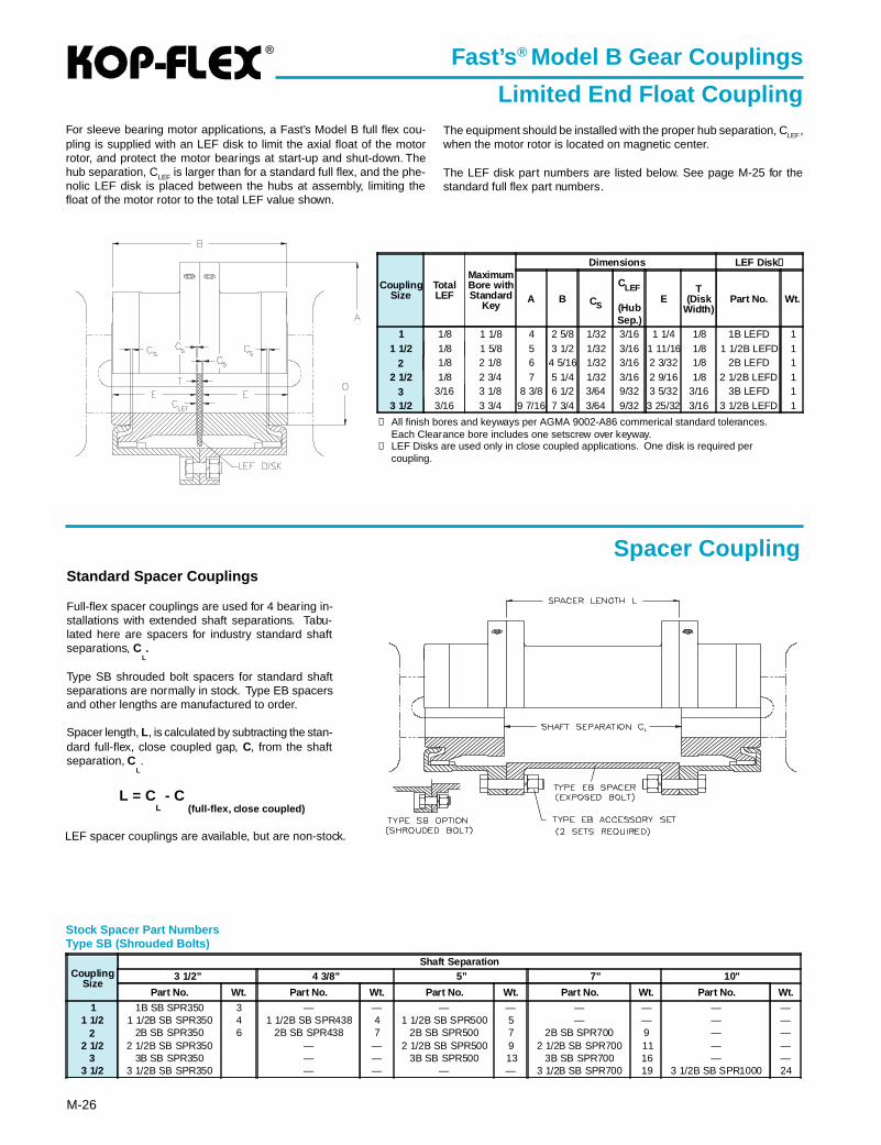
®
M-26
➀ All finish bores and keyways per AGMA 9002-A86 commerical standard tolerances.Each Clearance bore includes one setscrew over keyway.
➁ LEF Disks are used only in close coupled applications. One disk is required percoupling.
Fast’s ® Model B Gear Couplings
Limited End Float Coupling
Spacer Coupling
Stock Spacer Part NumbersType SB (Shrouded Bolts)
For sleeve bearing motor applications, a Fast’s Model B full flex cou-pling is supplied with an LEF disk to limit the axial float of the motorrotor, and protect the motor bearings at start-up and shut-down. Thehub separation, CLEF is larger than for a standard full flex, and the phe-nolic LEF disk is placed between the hubs at assembly, limiting thefloat of the motor rotor to the total LEF value shown.
The equipment should be installed with the proper hub separation, CLEF,when the motor rotor is located on magnetic center.
The LEF disk part numbers are listed below. See page M-25 for thestandard full flex part numbers.
CouplingSize
TotalLEF
MaximumBore withStandard
Key
Dimensions LEF Disk ➁
A B CS
CLEF
(HubSep.)
ET
(DiskWidth)
Part No. Wt.
1 1/8 1 1/8 4 2 5/8 1/32 3/16 1 1/4 1/8 1B LEFD 11 1/2 1/8 1 5/8 5 3 1/2 1/32 3/16 1 11/16 1/8 1 1/2B LEFD 1
2 1/8 2 1/8 6 4 5/16 1/32 3/16 2 3/32 1/8 2B LEFD 12 1/2 1/8 2 3/4 7 5 1/4 1/32 3/16 2 9/16 1/8 2 1/2B LEFD 1
3 3/16 3 1/8 8 3/8 6 1/2 3/64 9/32 3 5/32 3/16 3B LEFD 13 1/2 3/16 3 3/4 9 7/16 7 3/4 3/64 9/32 3 25/32 3/16 3 1/2B LEFD 1
Standard Spacer Couplings
Full-flex spacer couplings are used for 4 bearing in-stallations with extended shaft separations. Tabu-lated here are spacers for industry standard shaftseparations, C
L.
Type SB shrouded bolt spacers for standard shaftseparations are normally in stock. Type EB spacersand other lengths are manufactured to order.
Spacer length, L, is calculated by subtracting the stan-dard full-flex, close coupled gap, C, from the shaftseparation, C
L.
L = CL - C
(full-flex, close coupled)
LEF spacer couplings are available, but are non-stock.
CouplingSize
Shaft Separation3 1/2" 4 3/8" 5" 7" 10"
Part No. Wt. Part No. Wt. Part No. Wt. Part No. Wt. Part No. Wt.
1 1B SB SPR350 3 — — — — — — — —1 1/2 1 1/2B SB SPR350 4 1 1/2B SB SPR438 4 1 1/2B SB SPR500 5 — — — —
2 2B SB SPR350 6 2B SB SPR438 7 2B SB SPR500 7 2B SB SPR700 9 — —2 1/2 2 1/2B SB SPR350 — — 2 1/2B SB SPR500 9 2 1/2B SB SPR700 11 — —
3 3B SB SPR350 — — 3B SB SPR500 13 3B SB SPR700 16 — —3 1/2 3 1/2B SB SPR350 — — — — 3 1/2B SB SPR700 19 3 1/2B SB SPR1000 24
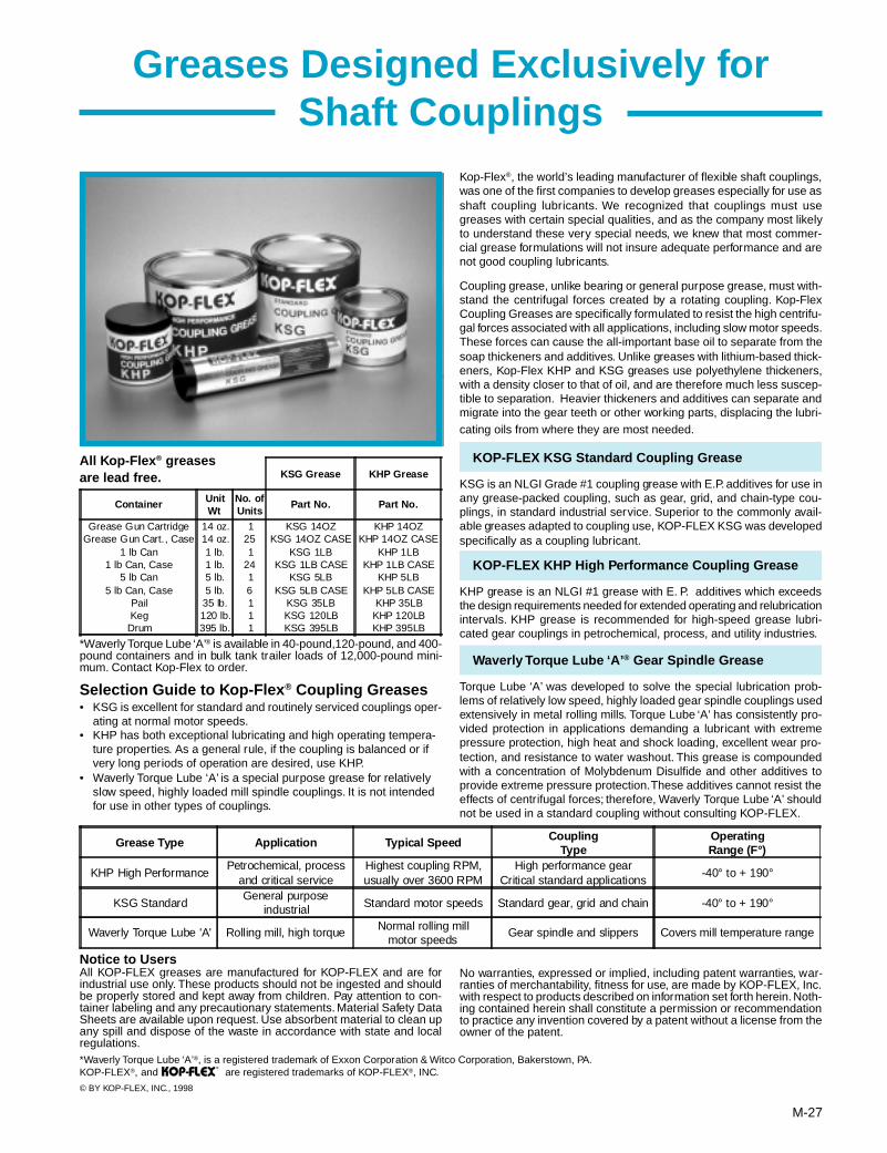
M-27
Selection Guide to Kop-Flex ® Coupling Greases• KSG is excellent for standard and routinely serviced couplings oper-
ating at normal motor speeds.• KHP has both exceptional lubricating and high operating tempera-
ture properties. As a general rule, if the coupling is balanced or ifvery long periods of operation are desired, use KHP.
• Waverly Torque Lube ‘A’ is a special purpose grease for relativelyslow speed, highly loaded mill spindle couplings. It is not intendedfor use in other types of couplings.
All Kop-Flex ® greasesare lead free.
*Waverly Torque Lube ‘A’® is available in 40-pound,120-pound, and 400-pound containers and in bulk tank trailer loads of 12,000-pound mini-mum. Contact Kop-Flex to order.
Notice to UsersAll KOP-FLEX greases are manufactured for KOP-FLEX and are forindustrial use only. These products should not be ingested and shouldbe properly stored and kept away from children. Pay attention to con-tainer labeling and any precautionary statements. Material Safety DataSheets are available upon request. Use absorbent material to clean upany spill and dispose of the waste in accordance with state and localregulations.*Waverly Torque Lube ‘A’®, is a registered trademark of Exxon Corporation & Witco Corporation, Bakerstown, PA.KOP-FLEX®, and are registered trademarks of KOP-FLEX®, INC.
© BY KOP-FLEX, INC., 1998
®
Greases Designed Exclusively forShaft Couplings
Kop-Flex®, the world’s leading manufacturer of flexible shaft couplings,was one of the first companies to develop greases especially for use asshaft coupling lubricants. We recognized that couplings must usegreases with certain special qualities, and as the company most likelyto understand these very special needs, we knew that most commer-cial grease formulations will not insure adequate performance and arenot good coupling lubricants.
Coupling grease, unlike bearing or general purpose grease, must with-stand the centrifugal forces created by a rotating coupling. Kop-FlexCoupling Greases are specifically formulated to resist the high centrifu-gal forces associated with all applications, including slow motor speeds.These forces can cause the all-important base oil to separate from thesoap thickeners and additives. Unlike greases with lithium-based thick-eners, Kop-Flex KHP and KSG greases use polyethylene thickeners,with a density closer to that of oil, and are therefore much less suscep-tible to separation. Heavier thickeners and additives can separate andmigrate into the gear teeth or other working parts, displacing the lubri-cating oils from where they are most needed.
KOP-FLEX KSG Standard Coupling Grease
KSG is an NLGI Grade #1 coupling grease with E.P. additives for use inany grease-packed coupling, such as gear, grid, and chain-type cou-plings, in standard industrial service. Superior to the commonly avail-able greases adapted to coupling use, KOP-FLEX KSG was developedspecifically as a coupling lubricant.
KOP-FLEX KHP High Performance Coupling Grease
KHP grease is an NLGI #1 grease with E. P. additives which exceedsthe design requirements needed for extended operating and relubricationintervals. KHP grease is recommended for high-speed grease lubri-cated gear couplings in petrochemical, process, and utility industries.
Waverly Torque Lube ‘A’ ® Gear Spindle Grease
Torque Lube ‘A’ was developed to solve the special lubrication prob-lems of relatively low speed, highly loaded gear spindle couplings usedextensively in metal rolling mills. Torque Lube ‘A’ has consistently pro-vided protection in applications demanding a lubricant with extremepressure protection, high heat and shock loading, excellent wear pro-tection, and resistance to water washout. This grease is compoundedwith a concentration of Molybdenum Disulfide and other additives toprovide extreme pressure protection. These additives cannot resist theeffects of centrifugal forces; therefore, Waverly Torque Lube ‘A’ shouldnot be used in a standard coupling without consulting KOP-FLEX.
Grease Type Application Typical Speed CouplingType
OperatingRange (F°)
KHP High PerformancePetrochemical, process
and critical serviceHighest coupling RPM,usually over 3600 RPM
High performance gearCritical standard applications
-40° to + 190°
KSG StandardGeneral purpose
industrial Standard motor speeds Standard gear, grid and chain -40° to + 190°
Waverly Torque Lube 'A' Rolling mill, high torque Normal rolling millmotor speeds
Gear spindle and slippers Covers mill temperature range
KSG Grease KHP Grease
Container UnitWt
No. ofUnits
Part No. Part No.
Grease Gun Cartridge 14 oz. 1 KSG 14OZ KHP 14OZGrease Gun Cart., Case 14 oz. 25 KSG 14OZ CASE KHP 14OZ CASE
1 lb Can 1 lb. 1 KSG 1LB KHP 1LB1 lb Can, Case 1 lb. 24 KSG 1LB CASE KHP 1LB CASE
5 lb Can 5 lb. 1 KSG 5LB KHP 5LB5 lb Can, Case 5 lb. 6 KSG 5LB CASE KHP 5LB CASE
Pail 35 lb. 1 KSG 35LB KHP 35LBKeg 120 lb. 1 KSG 120LB KHP 120LB
Drum 395 lb. 1 KSG 395LB KHP 395LB
No warranties, expressed or implied, including patent warranties, war-ranties of merchantability, fitness for use, are made by KOP-FLEX, Inc.with respect to products described on information set forth herein. Noth-ing contained herein shall constitute a permission or recommendationto practice any invention covered by a patent without a license from theowner of the patent.

M-28
®
RM Series
These couplings are engineered to accommodate a broad range of demanding operatingconditions: boiler feed pumps, centrifugal and axial compressors, generator sets, test stands,gas and steam turbines, marine drives, etc.
The Kop-Flex HP disc coupling is the preferred choice for demanding turbo machinery applications. Superiorquality and a wide variety of standard and custom designs backed by unsurpassed engineering expertisecombined to make Kop-Flex the industry leader.
• Inherent fail-safe designs• Koplon coated flexible disc elements for maximum life• Factory assembled• Greatest reduced moment available• Dynamically balanced
KOP-FLEX High Performance Flexible Diaphragm Couplings (For more Information, see Bulletin 1300)
The patented Flexible Diaphragm Coupling from KOP-FLEX transmits torque from the drivingshaft via a rigid hub, then through a flexible diaphragm to a spacer. The diaphragm deformswhile transmitting this torque to accommodate misalignment. The spacer in turn drives matchingcomponents attached to the driven equipment. Outstanding design features are:
• Field Replaceable Stockable Diaphragms• Specially-Contoured One-Piece Diaphragm
Design• Patented Diaphragm Shape• Piloted Fits• Diaphragms are 15.5 PH Shot-Peened
Stainless Steel• Inherently Low Windage Design• Conforms To API 671 Specifications
HIGH PERFORMANCE DISC COUPLINGS...Available In Four Standard Styles...Designed And Manufactured To Meet API 671 As A Standard (For more Information, see Bulletin HP103)
MS Series RZ Series MP Series
KOP-FLEX® Reduced MomentHigh Performance Disc Coupling
Size #5.5 MDM-Jdiaphragm coupling
KOP-FLEX High Performance Gear Couplings (For more Information, Contact KOP-FLEX)
• Thousands in Service• Choose From Straight or Crowned Nitrided Gear Teeth,
Depending on your Application• Precision Lapped Teeth, if Required• Heat Treated Alloy Components
Size #6 Gear CouplingG.E. MS5001 Gas Turbine Driven
Compressor Train.
HIGH PERFORMANCE COUPLINGS
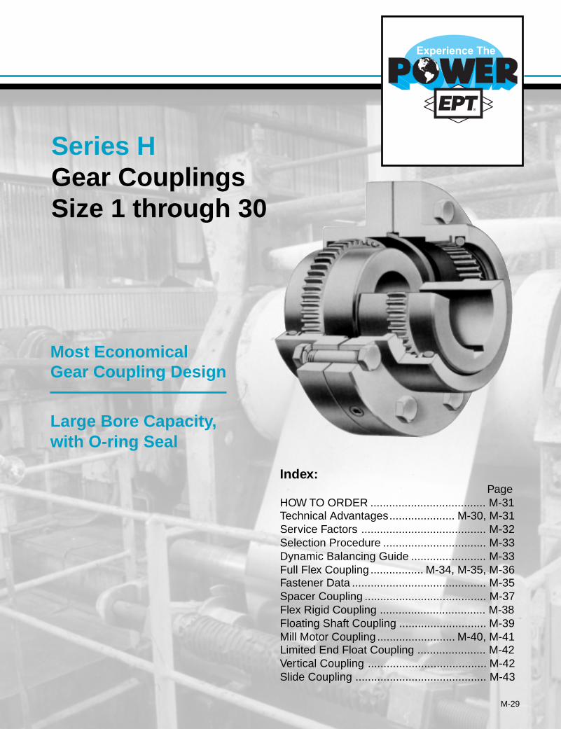
M-29
Index:Page
HOW TO ORDER ..................................... M-31Technical Advantages..................... M-30, M-31Service Factors ........................................ M-32Selection Procedure ................................. M-33Dynamic Balancing Guide ........................ M-33Full Flex Coupling ................. M-34, M-35, M-36Fastener Data ........................................... M-35Spacer Coupling ....................................... M-37Flex Rigid Coupling .................................. M-38Floating Shaft Coupling ............................ M-39Mill Motor Coupling ......................... M-40, M-41Limited End Float Coupling ...................... M-42Vertical Coupling ...................................... M-42Slide Coupling .......................................... M-43
Series HGear CouplingsSize 1 through 30
Most EconomicalGear Coupling Design
Large Bore Capacity,with O-ring Seal
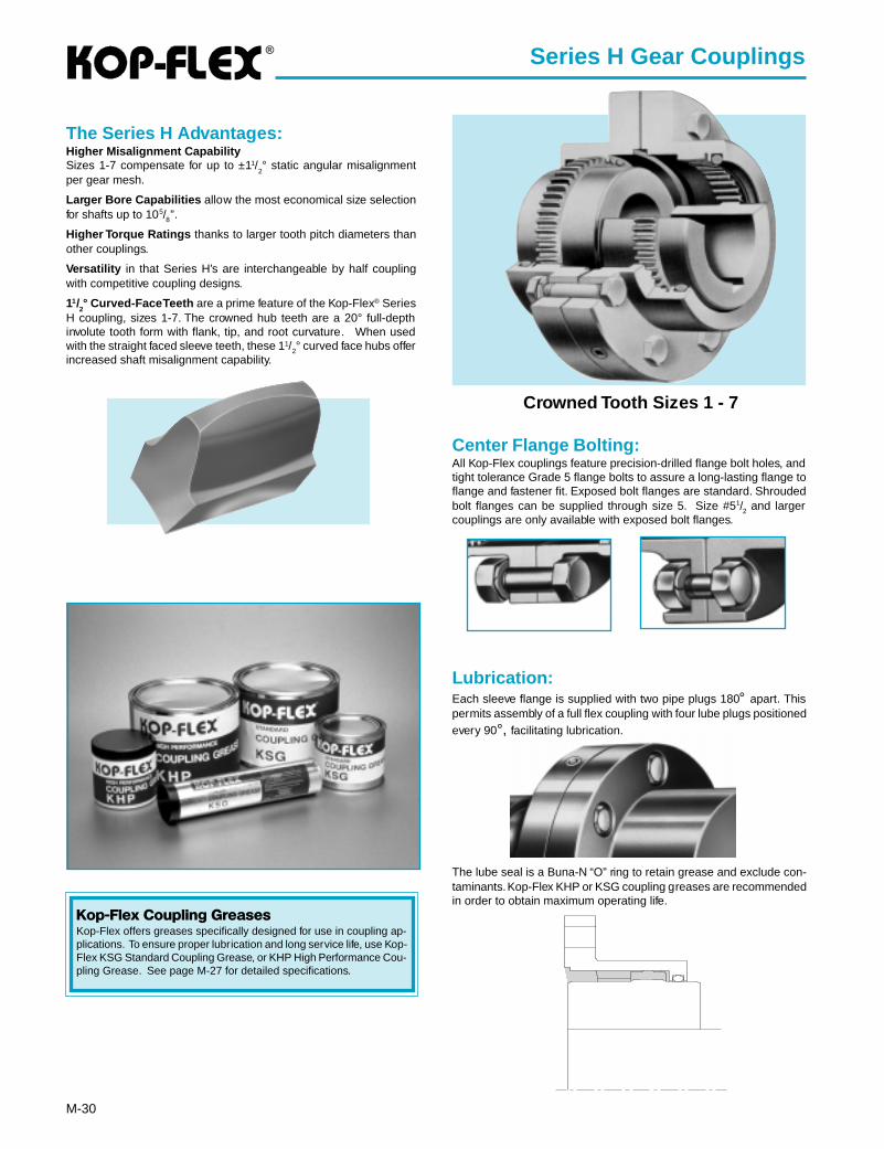
®
M-30
Series H Gear Couplings
The Series H Advantages:Higher Misalignment CapabilitySizes 1-7 compensate for up to ±11/
2° static angular misalignment
per gear mesh.
Larger Bore Capabilities allow the most economical size selectionfor shafts up to 105/8”.
Higher Torque Ratings thanks to larger tooth pitch diameters thanother couplings.
Versatility in that Series H’s are interchangeable by half couplingwith competitive coupling designs.
11/2° Curved-Face Teeth are a prime feature of the Kop-Flex® Series
H coupling, sizes 1-7. The crowned hub teeth are a 20° full-depthinvolute tooth form with flank, tip, and root curvature. When usedwith the straight faced sleeve teeth, these 11/2° curved face hubs offerincreased shaft misalignment capability.
Center Flange Bolting:All Kop-Flex couplings feature precision-drilled flange bolt holes, andtight tolerance Grade 5 flange bolts to assure a long-lasting flange toflange and fastener fit. Exposed bolt flanges are standard. Shroudedbolt flanges can be supplied through size 5. Size #51/2 and largercouplings are only available with exposed bolt flanges.
Lubrication:Each sleeve flange is supplied with two pipe plugs 180° apart. Thispermits assembly of a full flex coupling with four lube plugs positionedevery 90°, facilitating lubrication.
The lube seal is a Buna-N “O” ring to retain grease and exclude con-taminants. Kop-Flex KHP or KSG coupling greases are recommendedin order to obtain maximum operating life.
Crowned Tooth Sizes 1 - 7
Kop-Flex Coupling GreasesKop-Flex offers greases specifically designed for use in coupling ap-plications. To ensure proper lubrication and long service life, use Kop-Flex KSG Standard Coupling Grease, or KHP High Performance Cou-pling Grease. See page M-27 for detailed specifications.
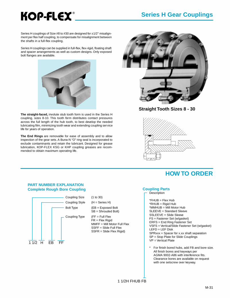
®
M-31
Series H Gear Couplings
PART NUMBER EXPLANATIONComplete Rough Bore Coupling
Coupling Size (1 to 30)
Coupling Style (H = Series H)
Bolt Type (EB = Exposed BoltSB = Shrouded Bolt)
Coupling Type (FF = Full FlexFR = Flex RigidMMFF = Mill Motor Full FlexSSFF = Slide Full FlexSSFR = Slide Flex Rigid)
1 1/2 H EB FF
Description
*FHUB = Flex Hub*RHUB = Rigid Hub*MMHUB = Mill Motor HubSLEEVE = Standard SleeveSSLEEVE = Slide SleeveFS = Fastener Set (w/gasket)ERFS = End Ring Fastener SetVSFS = Vertical/Slide Fastener Set (w/gasket)LEFD = LEF DiskSPRxxx = Spacer for x.xx shaft separationSP = Stop Plate for Slide CouplingsVP = Vertical Plate
* For finish bored hubs, add FB and bore size.All finish bores and keyways perAGMA 9002-A86 with interference fits.Clearance bores are available on requestwith one setscrew over keyway.
1 1/2H FHUB FB
Coupling Parts
Series H couplings of Size #8 to #30 are designed for ±1/2° misalign-ment per flex half coupling, to compensate for misalignment betweenthe shafts in a full-flex coupling.
Series H couplings can be supplied in full-flex, flex-rigid, floating shaftand spacer arrangements as well as custom designs. Only exposedbolt flanges are available.
The straight-faced, involute stub tooth form is used in the Series Hcoupling, sizes 8-10. This tooth form distributes contact pressuresacross the full length of the hub tooth, to best develop the neededlubricating film, minimizing tooth wear and extending coupling servicelife for years of operation.
The End Rings are removable for ease of assembly and to allowinspection of the gear sets. A Buna-N “O” ring seal is incorporated toexclude contaminants and retain the lubricant. Designed for greaselubrication, KOP-FLEX KSG or KHP coupling greases are recom-mended to obtain maximum operating life.
Straight Tooth Sizes 8 - 30
HOW TO ORDER

®
M-32
Series H Gear Couplings
Service Factors
TypicalApplication Ser vice
FactorAGITATORS
Pure Liquids .......................................................... 1.0Liquids & Solids .................................................... 1.25Liquids — Variable Density ................................... 1.25
BLOWERSCentrifugal ............................................................. 1.0Lobe ...................................................................... 1.5Vane ...................................................................... 1.25
BRIQUETTE MACHINES ........................................... 2.0CAR PULLERS — Intermittent Duty .......................... 1.5COMPRESSORS
Centrifugal ............................................................. 1.0Centriaxial ............................................................. 1.25Lobe ...................................................................... 1.5Reciprocating — Multi-Cylinder ............................ 2.0
CONVEYORS — LIGHT DUTY UNIFORMLY FEDApron, Bucket, Chain, Flight, Screw ..................... 1.25Assembly, Belt ....................................................... 1.0Oven ...................................................................... 1.5
CONVEYORS — HEAVY DUTY NOT UNIFORMLY FEDApron, Bucket, Chain, Flight, Oven ....................... 1.5Assembly, Belt ....................................................... 1.25Reciprocating, Shaker ........................................... 2.5
CRANES AND HOISTS (NOTE 1 and 2)Main hoists, Reversing .......................................... 2.5Skip Hoists, Trolley & Bridge Drives ...................... 2.0Slope ..................................................................... 2.0
CRUSHERSOre, Stone ............................................................. 3.0
DREDGESCable Reels ........................................................... 1.75Conveyors ............................................................. 1.5Cutter Head Jig Drives .......................................... 2.5Maneuvering Winches ........................................... 1.75Pumps ................................................................... 1.75Screen Drives ........................................................ 1.75Stackers ................................................................ 1.75Utility Winches ....................................................... 1.5
ELEVATORS (NOTE 2)Bucket ................................................................... 1.75Centrifugal & Gravity Discharge ........................... 1.5Escalators ............................................................. 1.5Freight ................................................................... 2.5
FANSCentrifugal ............................................................. 1.0Cooling Towers ...................................................... 1.5Forced Draft .......................................................... 1.5Induced Draft without Damper Control ............................................................... 2.0
FEEDERSApron, Belt, Disc, Screw ....................................... 1.25Reciprocating ........................................................ 2.5
TypicalApplication Ser vice
FactorGENERATORS —
(Not Welding) ........................................................... 1.0HAMMER MILLS ........................................................ 2.0LAUNDRY WASHERS —
Reversing ............................................................. 2.0LAUNDRY TUMBLERS ............................................. 2.0LINE SHAFT .............................................................. 1.5LUMBER INDUSTRY
Barkers — Drum Type ............................................. 2.0Edger Feed .............................................................. 2.0Live Rolls ................................................................. 2.0Log Haul — Incline .................................................. 2.0Log Haul — Well type .............................................. 2.0Off Bearing Rolls ...................................................... 2.0Planer Feed Chains ................................................. 1.75Planer Floor Chains ................................................. 1.75Planer Tilting Hoist ................................................... 1.75Slab Conveyor .......................................................... 1.5Sorting Table ............................................................ 1.5Trimmer Feed ........................................................... 1.75
MARINE PROPULSIONMain Drives .............................................................. 2.0
MACHINE TOOLSBending Roll ............................................................ 2.0Plate Planer ............................................................. 1.5Punch Press — Gear Driven ................................... 2.0Tapping Machines .................................................... 2.5Other Machine Tools Main Drives .......................................................... 1.5 Auxiliary Drives .................................................... 1.25
METAL MILLSDraw Bench — Carriage .......................................... 2.0Draw Bench — Main Drive ...................................... 2.0Forming Machines ................................................... 2.0Slitters ...................................................................... 1.5Table Conveyors Non-Reversing ..................................................... 2.25 Reversing ............................................................. 2.5Wire Drawing & Flattening Machine ........................ 2.0Wire Winding Machine ............................................. 1.75
METAL ROLLING MILLS (NOTE 1)Blooming Mills .......................................................... *Coilers, hot mill ........................................................ 2.0Coilers, cold mill ....................................................... 1.25Cold Mills ................................................................. 2.0Cooling Beds ........................................................... 1.75Door Openers .......................................................... 2.0Draw Benches .......................................................... 2.0Edger Drives ............................................................ 1.75Feed Rolls, Reversing Mills ..................................... 3.5Furnace Pushers ..................................................... 2.5Hot Mills ................................................................... 3.0Ingot Cars ................................................................ 2.5Kick-outs .................................................................. 2.5Manipulators ............................................................ 3.0Merchant Mills .......................................................... 3.0Piercers .................................................................... 3.0Pusher Rams ........................................................... 2.5Reel Drives .............................................................. 1.75Reel Drums .............................................................. 2.0Reelers ..................................................................... 3.0Rod and Bar Mills .................................................... 1.5Roughing Mill Delivery Table ................................... 3.0Runout Tables Reversing ............................................................. 3.0 Non-Reversing ..................................................... 2.0Saws, hot & cold ...................................................... 2.5Screwdown Drives ................................................... 3.0Skelp Mills ................................................................ 3.0Slitters ...................................................................... 3.0Slabbing Mills ........................................................... 3.0Soaking Pit Cover Drives ......................................... 3.0Straighteners ............................................................ 2.5Tables, transfer & runout .......................................... 2.0Thrust Block ............................................................. 3.0Traction Drive ........................................................... 3.0Tube Conveyor Rolls ................................................ 2.5Unscramblers ........................................................... 2.5Wire Drawing ........................................................... 1.5
MILLS, ROTARY TYPEBall ........................................................................... 2.25Dryers & Coolers ..................................................... 2.0Hammer ................................................................... 1.75Kilns ......................................................................... 2.0
TypicalApplication Ser vice
FactorPebble & Rod ........................................................... 2.0Pug ........................................................................... 1.75Tumbling Barrels ...................................................... 2.0
MIXERSConcrete Mixers ....................................................... 1.75Drum Type ................................................................ 1.5
OIL INDUSTRYChillers ..................................................................... 1.25Paraffin Filter Press ................................................. 1.75
PAPER MILLSBarker Auxiliaries, Hydraulic .................................... 2.0Barker, Mechanical .................................................. 2.0Barking Drum Spur Gear Only ................................ 2.25Beater & Pulper ....................................................... 1.75Bleacher ................................................................... 1.0Calenders ................................................................. 2.0Chippers ................................................................... 2.5Coaters .................................................................... 1.0Converting Machines, except Cutters, Platers .......................................... 1.5Couch Roll ............................................................... 1.75Cutters, Platers ........................................................ 2.0Cylinders .................................................................. 1.75Disc Refiners ........................................................... 1.75Dryers ...................................................................... 1.75Felt Stretcher ........................................................... 1.25Felt Whipper ............................................................. 2.0Jordans .................................................................... 1.75Line Shaft ................................................................. 1.5Log Haul ................................................................... 2.0Pulp Grinder ............................................................. 1.75Press Roll ................................................................. 2.0Reel .......................................................................... 1.5Stock Chests ............................................................ 1.5Suction Roll .............................................................. 1.75Washers & Thickeners ............................................. 1.5Winders .................................................................... 1.5
PRINTING PRESSES ................................................ 1.5PULLERS — Barge Haul ........................................... 2.0PUMPS
Centrifugal ............................................................... 1.0Boiler Feed ............................................................... 1.5Reciprocating Single Acting 1 or 2 Cylinders ................................................... 2.25 3 or more Cylinders ............................................ 1.75Double Acting ........................................................... 2.0Rotary, Gear, Lobe, Vane ......................................... 1.5
RUBBER INDUSTRYMixer — Banbury ..................................................... 2.5Rubber Calendar ..................................................... 2.0Rubber Mill (2 or more) ............................................ 2.25Sheeter .................................................................... 2.0Tire Building Machines ............................................ 2.5Tire & Tube Press Openers ..................................... 1.0Tubers & Strainers ................................................... 2.0
SCREENSAir Washing .............................................................. 1.0Grizzly ...................................................................... 2.0Rotary — Stone or Gravel ....................................... 1.5Traveling Water Intake ............................................. 1.25Vibrating ................................................................... 2.5
SEWAGE DISPOSAL EQUIPMENTBar Screens ............................................................. 1.25Chemical Feeders .................................................... 1.25Collectors, Circuline or Straightline ......................... 1.25Dewatering Screens ................................................ 1.25Grit Collectors .......................................................... 1.25Scum Breakers ........................................................ 1.25Slow or Rapid Mixers ............................................... 1.25Sludge Collectors ..................................................... 1.25Thickeners ............................................................... 1.25Vacuum Filters ......................................................... 1.25
STEERING GEAR ...................................................... 1.0STOKERS .................................................................. 1.0WINCH........................................................................ 1.5WINDLASS ................................................................ 1.75
* Refer to Kop-Flex
NOTES(1) Maximum Torque at the coupling must not exceed
Rated Torque of the coupling.(2) Check local and industrial safety codes.
Values listed are intended only as a generalguide, and are typical of usual service re-quirements. For systems which frequentlyutilize the peak torque capability of the powersource, verify that the magnitude of this peaktorque does not exceed the 1.0 Service Fac-tor Rating of the coupling selected. Applica-tions which involve extreme repetitive shockor high-energy load absorption characteris-tics should be referred — with full particu-lars — to KOP-FLEX.Values contained in the table are to be ap-plied to smooth power sources such as elec-tric motors and steam turbines. For drivesinvolving internal combustion, engines of fouror five cylinders, add 1.0 to the values listed,for six or more cylinders, add 0.5 to the val-ues listed. For systems utilizing AC or DCMill Motors as the prime mover refer to Note(1).
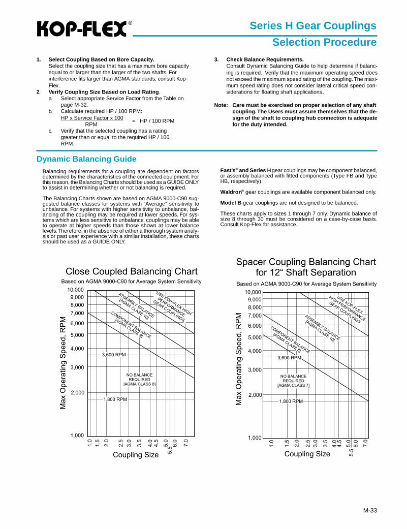
®
M-33
Dynamic Balancing GuideBalancing requirements for a coupling are dependent on factorsdetermined by the characteristics of the connected equipment. Forthis reason, the Balancing Charts should be used as a GUIDE ONLYto assist in determining whether or not balancing is required.
The Balancing Charts shown are based on AGMA 9000-C90 sug-gested balance classes for systems with “Average” sensitivity tounbalance. For systems with higher sensitivity to unbalance, bal-ancing of the coupling may be required at lower speeds. For sys-tems which are less sensitive to unbalance, couplings may be ableto operate at higher speeds than those shown at lower balancelevels. Therefore, in the absence of either a thorough system analy-sis or past user experience with a similar installation, these chartsshould be used as a GUIDE ONLY.
Series H Gear Couplings
Selection Procedure1. Select Coupling Based on Bore Capacity.
Select the coupling size that has a maximum bore capacityequal to or larger than the larger of the two shafts. Forinterference fits larger than AGMA standards, consult Kop-Flex.
2. Verify Coupling Size Based on Load Rating .a. Select appropriate Service Factor from the Table on
page M-32.b. Calculate required HP / 100 RPM:
HP x Service Factor x 100RPM
= HP / 100 RPM
c. Verify that the selected coupling has a ratinggreater than or equal to the required HP / 100RPM.
3. Check Balance Requirements.Consult Dynamic Balancing Guide to help determine if balanc-ing is required. Verify that the maximum operating speed doesnot exceed the maximum speed rating of the coupling. The maxi-mum speed rating does not consider lateral critical speed con-siderations for floating shaft applications.
Note: Care must be exercised on proper selection of any shaftcoupling. The Users must assure themselves that the de-sign of the shaft to coupling hub connection is adequatefor the duty intended.
Fast’s ® and Series H gear couplings may be component balanced,or assembly balanced with fitted components (Type FB and TypeHB, respectively).
Waldron ® gear couplings are available component balanced only.
Model B gear couplings are not designed to be balanced.
These charts apply to sizes 1 through 7 only. Dynamic balance ofsize 8 through 30 must be considered on a case-by-case basis.Consult Kop-Flex for assistance.
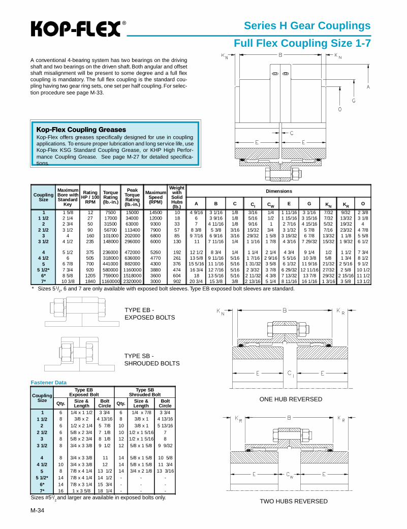
®
M-34
Series H Gear Couplings
Full Flex Coupling Size 1-7A conventional 4-bearing system has two bearings on the drivingshaft and two bearings on the driven shaft. Both angular and offsetshaft misalignment will be present to some degree and a full flexcoupling is mandatory. The full flex coupling is the standard cou-pling having two gear ring sets, one set per half coupling. For selec-tion procedure see page M-33.
TYPE SB -SHROUDED BOLTS
TYPE EB -EXPOSED BOLTS
Kop-Flex Coupling GreasesKop-Flex offers greases specifically designed for use in couplingapplications. To ensure proper lubrication and long service life, useKop-Flex KSG Standard Coupling Grease, or KHP High Perfor-mance Coupling Grease. See page M-27 for detailed specifica-tions.
* Sizes 51/2, 6 and 7 are only available with exposed bolt sleeves. Type EB exposed bolt sleeves are standard.
Sizes #51/2 and larger are available in exposed bolts only.
Fastener Data
ONE HUB REVERSED
TWO HUBS REVERSED
CouplingSize
Type EBExposed Bolt
Type SBShrouded Bolt
Qty. Size &Length
BoltCircle Qty. Size &
LengthBolt
Circle1 6 1/4 x 1 1/2 3 3/4 6 1/4 x 7/8 3 3/4
1 1/2 8 3/8 x 2 4 13/16 8 3/8 x 1 4 13/162 6 1/2 x 2 1/4 5 7/8 10 3/8 x 1 5 13/16
2 1/2 6 5/8 x 2 3/4 7 1/8 10 1/2 x 1 5/16 73 8 5/8 x 2 3/4 8 1/8 12 1/2 x 1 5/16 8
3 1/2 8 3/4 x 3 3/8 9 1/2 12 5/8 x 1 5/8 9 9/32
4 8 3/4 x 3 3/8 11 14 5/8 x 1 5/8 10 5/84 1/2 10 3/4 x 3 3/8 12 14 5/8 x 1 5/8 11 3/4
5 8 7/8 x 4 1/4 13 1/2 14 3/4 x 2 1/8 13 3/165 1/2* 14 7/8 x 4 1/4 14 1/2 - - -
6* 14 7/8 x 3 1/4 15 3/4 - - -7* 16 1 x 3 5/8 18 1/4 - - -
CouplingSize
MaximumBore withStandard
Key
RatingHP / 100
RPM
TorqueRating(lb.-in.)
PeakTorqueRating(lb.-in.)
MaximumSpeed(RPM)
WeightwithSolidHubs(lb.)
Dimensions
A B C CI CWE G KN KR
O
1 1 5/8 12 7500 15000 14500 10 4 9/16 3 1/16 1/8 3/16 1/4 1 11/16 3 1/16 7/32 9/32 2 3/81 1/2 2 1/4 27 17000 34000 12000 18 6 3 9/16 1/8 5/16 1/2 1 15/16 3 15/16 7/32 13/32 3 1/8
2 2 3/4 50 31500 63000 9300 33 7 4 11/16 1/8 9/16 1 2 7/16 4 15/16 5/32 19/32 42 1/2 3 1/2 90 56700 113400 7900 57 8 3/8 5 3/8 3/16 15/32 3/4 3 1/32 5 7/8 7/16 23/32 4 7/8
3 4 160 101000 202000 6800 85 9 7/16 6 9/16 3/16 29/32 1 5/8 3 19/32 6 7/8 13/32 1 1/8 5 5/83 1/2 4 1/2 235 148000 296000 6000 130 11 7 11/16 1/4 1 1/16 1 7/8 4 3/16 7 29/32 15/32 1 9/32 6 1/2
4 5 1/2 375 236000 472000 5260 192 12 1/2 8 3/4 1/4 1 1/4 2 1/4 4 3/4 9 1/4 1/2 1 1/2 7 3/44 1/2 6 505 318000 636000 4770 261 13 5/8 9 11/16 5/16 1 7/16 2 9/16 5 5/16 10 3/8 5/8 1 3/4 8 1/2
5 6 7/8 700 441000 882000 4300 376 15 5/16 11 1/16 5/16 1 31/32 3 5/8 6 1/32 11 9/16 21/32 2 5/16 9 1/25 1/2* 7 3/4 920 580000 1160000 3880 474 16 3/4 12 7/16 5/16 2 3/32 3 7/8 6 29/32 12 11/16 27/32 2 5/8 10 1/2
6* 8 5/8 1205 759000 1518000 3600 604 18 13 5/16 5/16 2 11/32 4 3/8 7 13/32 13 7/8 29/32 2 15/16 11 1/27* 10 3/8 1840 1160000 2320000 3000 902 20 3/4 15 3/8 3/8 2 13/16 5 1/4 8 11/16 16 1/16 1 3/16 3 5/8 13 1/2
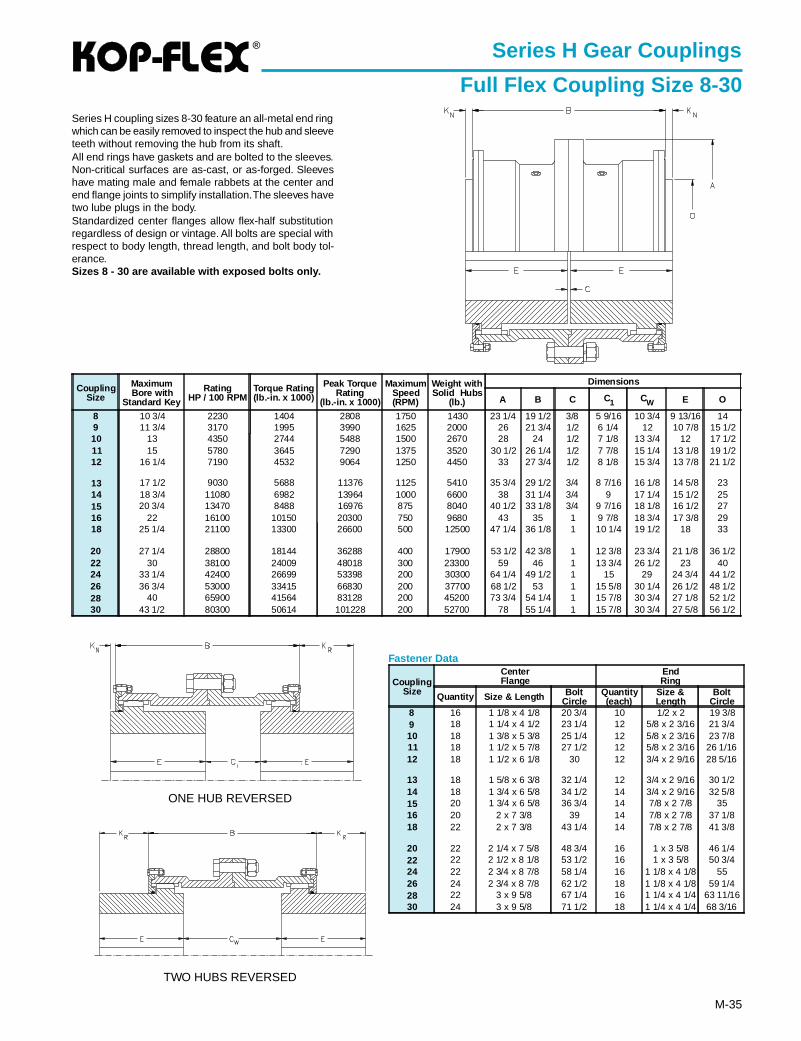
®
M-35
Series H Gear Couplings
Full Flex Coupling Size 8-30Series H coupling sizes 8-30 feature an all-metal end ringwhich can be easily removed to inspect the hub and sleeveteeth without removing the hub from its shaft.All end rings have gaskets and are bolted to the sleeves.Non-critical surfaces are as-cast, or as-forged. Sleeveshave mating male and female rabbets at the center andend flange joints to simplify installation. The sleeves havetwo lube plugs in the body.Standardized center flanges allow flex-half substitutionregardless of design or vintage. All bolts are special withrespect to body length, thread length, and bolt body tol-erance.Sizes 8 - 30 are available with exposed bolts only.
ONE HUB REVERSED
TWO HUBS REVERSED
Fastener Data
CouplingSize
CenterFlange
EndRing
Quantity Size & Length BoltCircle
Quantity(each)
Size &Length
BoltCircle
8 16 1 1/8 x 4 1/8 20 3/4 10 1/2 x 2 19 3/89 18 1 1/4 x 4 1/2 23 1/4 12 5/8 x 2 3/16 21 3/410 18 1 3/8 x 5 3/8 25 1/4 12 5/8 x 2 3/16 23 7/811 18 1 1/2 x 5 7/8 27 1/2 12 5/8 x 2 3/16 26 1/1612 18 1 1/2 x 6 1/8 30 12 3/4 x 2 9/16 28 5/16
13 18 1 5/8 x 6 3/8 32 1/4 12 3/4 x 2 9/16 30 1/214 18 1 3/4 x 6 5/8 34 1/2 14 3/4 x 2 9/16 32 5/815 20 1 3/4 x 6 5/8 36 3/4 14 7/8 x 2 7/8 3516 20 2 x 7 3/8 39 14 7/8 x 2 7/8 37 1/818 22 2 x 7 3/8 43 1/4 14 7/8 x 2 7/8 41 3/8
20 22 2 1/4 x 7 5/8 48 3/4 16 1 x 3 5/8 46 1/422 22 2 1/2 x 8 1/8 53 1/2 16 1 x 3 5/8 50 3/424 22 2 3/4 x 8 7/8 58 1/4 16 1 1/8 x 4 1/8 5526 24 2 3/4 x 8 7/8 62 1/2 18 1 1/8 x 4 1/8 59 1/428 22 3 x 9 5/8 67 1/4 16 1 1/4 x 4 1/4 63 11/1630 24 3 x 9 5/8 71 1/2 18 1 1/4 x 4 1/4 68 3/16
CouplingSize
MaximumBore with
Standard Key
RatingHP / 100 RPM
Torque Rating(lb.-in. x 1000)
Peak TorqueRating
(lb.-in. x 1000)
MaximumSpeed(RPM)
Weight withSolid Hubs
(lb.)
Dimensions
A B C C1 CW E O
8 10 3/4 2230 1404 2808 1750 1430 23 1/4 19 1/2 3/8 5 9/16 10 3/4 9 13/16 149 11 3/4 3170 1995 3990 1625 2000 26 21 3/4 1/2 6 1/4 12 10 7/8 15 1/210 13 4350 2744 5488 1500 2670 28 24 1/2 7 1/8 13 3/4 12 17 1/211 15 5780 3645 7290 1375 3520 30 1/2 26 1/4 1/2 7 7/8 15 1/4 13 1/8 19 1/212 16 1/4 7190 4532 9064 1250 4450 33 27 3/4 1/2 8 1/8 15 3/4 13 7/8 21 1/2
13 17 1/2 9030 5688 11376 1125 5410 35 3/4 29 1/2 3/4 8 7/16 16 1/8 14 5/8 2314 18 3/4 11080 6982 13964 1000 6600 38 31 1/4 3/4 9 17 1/4 15 1/2 2515 20 3/4 13470 8488 16976 875 8040 40 1/2 33 1/8 3/4 9 7/16 18 1/8 16 1/2 2716 22 16100 10150 20300 750 9680 43 35 1 9 7/8 18 3/4 17 3/8 2918 25 1/4 21100 13300 26600 500 12500 47 1/4 36 1/8 1 10 1/4 19 1/2 18 33
20 27 1/4 28800 18144 36288 400 17900 53 1/2 42 3/8 1 12 3/8 23 3/4 21 1/8 36 1/222 30 38100 24009 48018 300 23300 59 46 1 13 3/4 26 1/2 23 4024 33 1/4 42400 26699 53398 200 30300 64 1/4 49 1/2 1 15 29 24 3/4 44 1/226 36 3/4 53000 33415 66830 200 37700 68 1/2 53 1 15 5/8 30 1/4 26 1/2 48 1/228 40 65900 41564 83128 200 45200 73 3/4 54 1/4 1 15 7/8 30 3/4 27 1/8 52 1/230 43 1/2 80300 50614 101228 200 52700 78 55 1/4 1 15 7/8 30 3/4 27 5/8 56 1/2
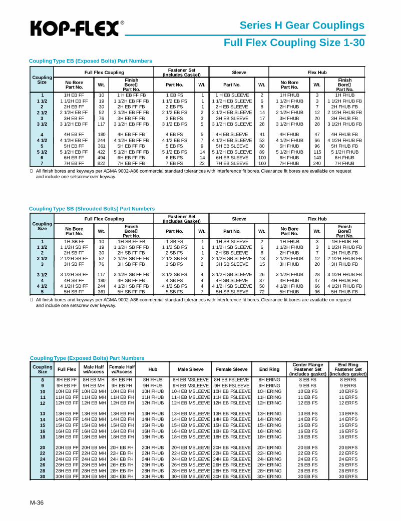
®
M-36
Coupling Type (Exposed Bolts) Part Numbers
Series H Gear Couplings
Full Flex Coupling Size 1-30
Coupling Type SB (Shrouded Bolts) Part Numbers
➀ All finish bores and keyways per AGMA 9002-A86 commercial standard tolerances with interference fit bores. Clearance fit bores are available on requestand include one setscrew over keyway.
Coupling Type EB (Exposed Bolts) Part Numbers
➀ All finish bores and keyways per AGMA 9002-A86 commercial standard tolerances with interference fit bores. Clearance fit bores are available on requestand include one setscrew over keyway.
CouplingSize
Full Flex Coupling Fastener Set(Includes Gasket) Sleeve Flex Hub
No BorePart No. Wt.
FinishBore ➀
Part No.Part No. Wt. Part No. Wt. No Bore
Part No. Wt.FinishBore ➀
Part No.1 1H EB FF 10 1 H EB FF FB 1 EB FS 1 1 H EB SLEEVE 2 1H FHUB 3 1H FHUB
1 1/2 1 1/2H EB FF 19 1 1/2H EB FF FB 1 1/2 EB FS 1 1 1/2H EB SLEEVE 6 1 1/2H FHUB 3 1 1/2H FHUB FB2 2H EB FF 30 2H EB FF FB 2 EB FS 1 2H EB SLEEVE 8 2H FHUB 7 2H FHUB FB
2 1/2 2 1/2H EB FF 52 2 1/2H EB FF FB 2 1/2 EB FS 2 2 1/2H EB SLEEVE 14 2 1/2H FHUB 12 2 1/2H FHUB FB3 3H EB FF 76 3H EB FF FB 3 EB FS 3 3H EB SLEEVE 17 3H FHUB 20 3H FHUB FB
3 1/2 3 1/2H EB FF 117 3 1/2H EB FF FB 3 1/2 EB FS 5 3 1/2H EB SLEEVE 28 3 1/2H FHUB 28 3 1/2H FHUB FB
4 4H EB FF 180 4H EB FF FB 4 EB FS 5 4H EB SLEEVE 41 4H FHUB 47 4H FHUB FB4 1/2 4 1/2H EB FF 244 4 1/2H EB FF FB 4 1/2 EB FS 7 4 1/2H EB SLEEVE 53 4 1/2H FHUB 66 4 1/2H FHUB FB
5 5H EB FF 361 5H EB FF FB 5 EB FS 9 5H EB SLEEVE 80 5H FHUB 96 5H FHUB FB5 1/2 5 1/2H EB FF 422 5 1/2H EB FF FB 5 1/2 EB FS 14 5 1/2H EB SLEEVE 89 5 1/2H FHUB 115 5 1/2H FHUB
6 6H EB FF 494 6H EB FF FB 6 EB FS 14 6H EB SLEEVE 100 6H FHUB 140 6H FHUB7 7H EB FF 822 7H EB FF FB 7 EB FS 22 7H EB SLEEVE 160 7H FHUB 240 7H FHUB
CouplingSize
Full Flex Coupling Fastener Set(Includes Gasket) Sleeve Flex Hub
No BorePart No. Wt.
FinishBore ➀
Part No.Part No. Wt. Part No. Wt. No Bore
Part No. Wt.FinishBore ➀
Part No.1 1H SB FF 10 1H SB FF FB 1 SB FS 1 1H SB SLEEVE 2 1H FHUB 3 1H FHUB FB
1 1/2 1 1/2H SB FF 19 1 1/2H SB FF FB 1 1/2 SB FS 1 1 1/2H SB SLEEVE 6 1 1/2H FHUB 3 1 1/2H FHUB FB2 2H SB FF 30 2H SB FF FB 2 SB FS 1 2H SB SLEEVE 8 2H FHUB 7 2H FHUB FB
2 1/2 2 1/2H SB FF 52 2 1/2H SB FF FB 2 1/2 SB FS 2 2 1/2H SB SLEEVE 13 2 1/2H FHUB 12 2 1/2H FHUB FB3 3H SB FF 76 3H SB FF FB 3 SB FS 2 3H SB SLEEVE 15 3H FHUB 20 3H FHUB FB
3 1/2 3 1/2H SB FF 117 3 1/2H SB FF FB 3 1/2 SB FS 4 3 1/2H SB SLEEVE 26 3 1/2H FHUB 28 3 1/2H FHUB FB4 4H SB FF 180 4H SB FF FB 4 SB FS 4 4H SB SLEEVE 37 4H FHUB 47 4H FHUB FB
4 1/2 4 1/2H SB FF 244 4 1/2H SB FF FB 4 1/2 SB FS 4 4 1/2H SB SLEEVE 50 4 1/2H FHUB 66 4 1/2H FHUB FB5 5H SB FF 361 5H SB FF FB 5 SB FS 7 5H SB SLEEVE 72 5H FHUB 96 5H FHUB FB
CouplingSize Full Flex Male Half
w/AccessFemale Halfw/Access Hub Male Sleeve Female Sleeve End Ring
Center FlangeFastener Set
(includes gasket)
End RingFastener Set
(includes gasket)8 8H EB FF 8H EB MH 8H EB FH 8H FHUB 8H EB MSLEEVE 8H EB FSLEEVE 8H ERING 8 EB FS 8 ERFS9 9H EB FF 9H EB MH 9H EB FH 9H FHUB 9H EB MSLEEVE 9H EB FSLEEVE 9H ERING 9 EB FS 9 ERFS
10 10H EB FF 10H EB MH 10H EB FH 10H FHUB 10H EB MSLEEVE 10H EB FSLEEVE 10H ERING 10 EB FS 10 ERFS11 11H EB FF 11H EB MH 11H EB FH 11H FHUB 11H EB MSLEEVE 11H EB FSLEEVE 11H ERING 11 EB FS 11 ERFS12 12H EB FF 12H EB MH 12H EB FH 12H FHUB 12H EB MSLEEVE 12H EB FSLEEVE 12H ERING 12 EB FS 12 ERFS
13 13H EB FF 13H EB MH 13H EB FH 13H FHUB 13H EB MSLEEVE 13H EB FSLEEVE 13H ERING 13 EB FS 13 ERFS14 14H EB FF 14H EB MH 14H EB FH 14H FHUB 14H EB MSLEEVE 14H EB FSLEEVE 14H ERING 14 EB FS 14 ERFS15 15H EB FF 15H EB MH 15H EB FH 15H FHUB 15H EB MSLEEVE 15H EB FSLEEVE 15H ERING 15 EB FS 15 ERFS16 16H EB FF 16H EB MH 16H EB FH 16H FHUB 16H EB MSLEEVE 16H EB FSLEEVE 16H ERING 16 EB FS 16 ERFS18 18H EB FF 18H EB MH 18H EB FH 18H FHUB 18H EB MSLEEVE 18H EB FSLEEVE 18H ERING 18 EB FS 18 ERFS
20 20H EB FF 20H EB MH 20H EB FH 20H FHUB 20H EB MSLEEVE 20H EB FSLEEVE 20H ERING 20 EB FS 20 ERFS22 22H EB FF 22H EB MH 22H EB FH 22H FHUB 22H EB MSLEEVE 22H EB FSLEEVE 22H ERING 22 EB FS 22 ERFS24 24H EB FF 24H EB MH 24H EB FH 24H FHUB 24H EB MSLEEVE 24H EB FSLEEVE 24H ERING 24 EB FS 24 ERFS26 26H EB FF 26H EB MH 26H EB FH 26H FHUB 26H EB MSLEEVE 26H EB FSLEEVE 26H ERING 26 EB FS 26 ERFS28 28H EB FF 28H EB MH 28H EB FH 28H FHUB 28H EB MSLEEVE 28H EB FSLEEVE 28H ERING 28 EB FS 28 ERFS30 30H EB FF 30H EB MH 30H EB FH 30H FHUB 30H EB MSLEEVE 30H EB FSLEEVE 30H ERING 30 EB FS 30 ERFS
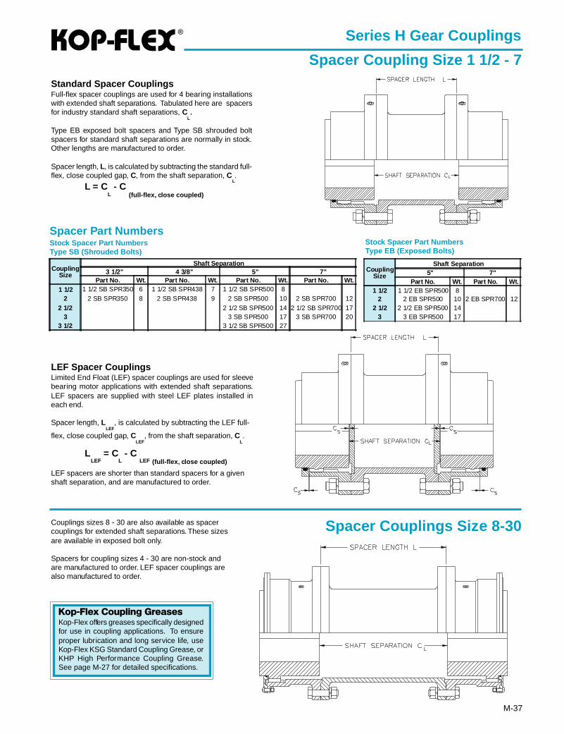
®
M-37
Standard Spacer CouplingsFull-flex spacer couplings are used for 4 bearing installationswith extended shaft separations. Tabulated here are spacersfor industry standard shaft separations, C
L.
Type EB exposed bolt spacers and Type SB shrouded boltspacers for standard shaft separations are normally in stock.Other lengths are manufactured to order.
Spacer length, L, is calculated by subtracting the standard full-flex, close coupled gap, C, from the shaft separation, C
L.
L = CL - C
(full-flex, close coupled)
Spacer Part NumbersStock Spacer Part NumbersType SB (Shrouded Bolts)
Stock Spacer Part NumbersType EB (Exposed Bolts)
LEF Spacer CouplingsLimited End Float (LEF) spacer couplings are used for sleevebearing motor applications with extended shaft separations.LEF spacers are supplied with steel LEF plates installed ineach end.
Spacer length, LLEF
, is calculated by subtracting the LEF full-
flex, close coupled gap, CLEF
, from the shaft separation, CL.
LLEF
= CL - C
LEF (full-flex, close coupled)
LEF spacers are shorter than standard spacers for a givenshaft separation, and are manufactured to order.
Series H Gear Couplings
Spacer Coupling Size 1 1/2 - 7
Spacer Couplings Size 8-30Couplings sizes 8 - 30 are also available as spacercouplings for extended shaft separations. These sizesare available in exposed bolt only.
Spacers for coupling sizes 4 - 30 are non-stock andare manufactured to order. LEF spacer couplings arealso manufactured to order.
CouplingSize
Shaft Separation3 1/2" 4 3/8" 5" 7"
Part No. Wt. Part No. Wt. Part No. Wt. Part No. Wt.1 1/2 1 1/2 SB SPR350 6 1 1/2 SB SPR438 7 1 1/2 SB SPR500 8
2 2 SB SPR350 8 2 SB SPR438 9 2 SB SPR500 10 2 SB SPR700 122 1/2 2 1/2 SB SPR500 14 2 1/2 SB SPR700 17
3 3 SB SPR500 17 3 SB SPR700 203 1/2 3 1/2 SB SPR500 27
CouplingSize
Shaft Separation5" 7"
Part No. Wt. Part No. Wt.1 1/2 1 1/2 EB SPR500 8
2 2 EB SPR500 10 2 EB SPR700 122 1/2 2 1/2 EB SPR500 14
3 3 EB SPR500 17
Kop-Flex Coupling GreasesKop-Flex offers greases specifically designedfor use in coupling applications. To ensureproper lubrication and long service life, useKop-Flex KSG Standard Coupling Grease, orKHP High Performance Coupling Grease.See page M-27 for detailed specifications.
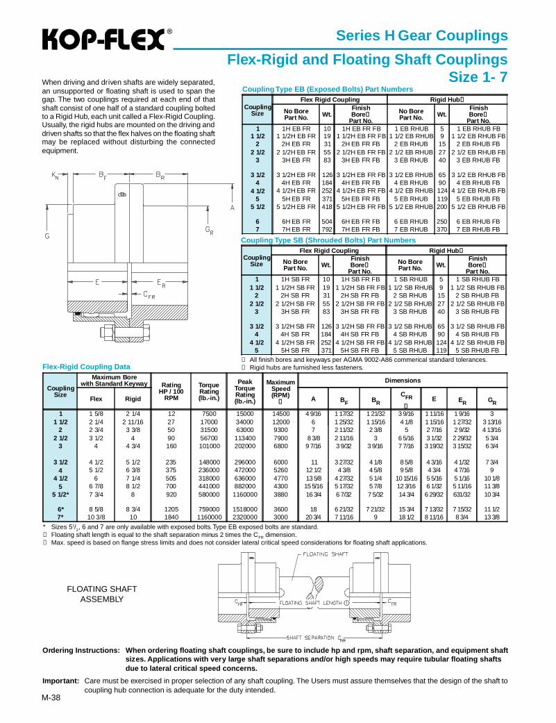
®
M-38
Coupling Type SB (Shrouded Bolts) Part Numbers
Coupling Type EB (Exposed Bolts) Part Numbers
➀ All finish bores and keyways per AGMA 9002-A86 commerical standard tolerances.➁ Rigid hubs are furnished less fasteners.
Ordering Instructions: When ordering floating shaft couplings, be sure to include hp and rpm, shaft separation, and equipment sh aftsizes. Applications with very large shaft separations and/or high speeds may require tubular floating shaftsdue to lateral critical speed concerns.
Impor tant: Care must be exercised in proper selection of any shaft coupling. The Users must assure themselves that the design of the shaft tocoupling hub connection is adequate for the duty intended.
Series H Gear Couplings
Flex-Rigid and Floating Shaft CouplingsSize 1- 7
FLOATING SHAFTASSEMBLY
When driving and driven shafts are widely separated,an unsupported or floating shaft is used to span thegap. The two couplings required at each end of thatshaft consist of one half of a standard coupling boltedto a Rigid Hub, each unit called a Flex-Rigid Coupling.Usually, the rigid hubs are mounted on the driving anddriven shafts so that the flex halves on the floating shaftmay be replaced without disturbing the connectedequipment.
* Sizes 51/2, 6 and 7 are only available with exposed bolts. Type EB exposed bolts are standard.
➀ Floating shaft length is equal to the shaft separation minus 2 times the CFR dimension.➁ Max. speed is based on flange stress limits and does not consider lateral critical speed considerations for floating shaft applications.
Flex-Rigid Coupling Data
CouplingSize
Flex Rigid Coupling Rigid Hub ➁
No BorePart No. Wt.
FinishBore ➀
Part No.
No BorePart No. Wt.
FinishBore ➀
Part No.1 1H EB FR 10 1H EB FR FB 1 EB RHUB 5 1 EB RHUB FB
1 1/2 1 1/2H EB FR 19 1 1/2H EB FR FB 1 1/2 EB RHUB 9 1 1/2 EB RHUB FB2 2H EB FR 31 2H EB FR FB 2 EB RHUB 15 2 EB RHUB FB
2 1/2 2 1/2H EB FR 55 2 1/2H EB FR FB 2 1/2 EB RHUB 27 2 1/2 EB RHUB FB3 3H EB FR 83 3H EB FR FB 3 EB RHUB 40 3 EB RHUB FB
3 1/2 3 1/2H EB FR 126 3 1/2H EB FR FB 3 1/2 EB RHUB 65 3 1/2 EB RHUB FB4 4H EB FR 184 4H EB FR FB 4 EB RHUB 90 4 EB RHUB FB
4 1/2 4 1/2H EB FR 252 4 1/2H EB FR FB 4 1/2 EB RHUB 124 4 1/2 EB RHUB FB5 5H EB FR 371 5H EB FR FB 5 EB RHUB 119 5 EB RHUB FB
5 1/2 5 1/2H EB FR 418 5 1/2H EB FR FB 5 1/2 EB RHUB 200 5 1/2 EB RHUB FB
6 6H EB FR 504 6H EB FR FB 6 EB RHUB 250 6 EB RHUB FB7 7H EB FR 792 7H EB FR FB 7 EB RHUB 370 7 EB RHUB FB
CouplingSize
Flex Rigid Coupling Rigid Hub ➁
No BorePart No. Wt.
FinishBore ➀
Part No.
No BorePart No. Wt.
FinishBore ➀
Part No.1 1H SB FR 10 1H SB FR FB 1 SB RHUB 5 1 SB RHUB FB
1 1/2 1 1/2H SB FR 19 1 1/2H SB FR FB 1 1/2 SB RHUB 9 1 1/2 SB RHUB FB2 2H SB FR 31 2H SB FR FB 2 SB RHUB 15 2 SB RHUB FB
2 1/2 2 1/2H SB FR 55 2 1/2H SB FR FB 2 1/2 SB RHUB 27 2 1/2 SB RHUB FB3 3H SB FR 83 3H SB FR FB 3 SB RHUB 40 3 SB RHUB FB
3 1/2 3 1/2H SB FR 126 3 1/2H SB FR FB 3 1/2 SB RHUB 65 3 1/2 SB RHUB FB4 4H SB FR 184 4H SB FR FB 4 SB RHUB 90 4 SB RHUB FB
4 1/2 4 1/2H SB FR 252 4 1/2H SB FR FB 4 1/2 SB RHUB 124 4 1/2 SB RHUB FB5 5H SB FR 371 5H SB FR FB 5 SB RHUB 119 5 SB RHUB FB
CouplingSize
Maximum Borewith Standard Keyway Rating
HP / 100RPM
TorqueRating(lb.-in.)
PeakTorqueRating(lb.-in.)
MaximumSpeed(RPM)
➁
Dimensions
Flex Rigid A BF BR
CFR
➀E ER GR
1 1 5/8 2 1/4 12 7500 15000 14500 4 9/16 1 17/32 1 21/32 3 9/16 1 11/16 1 9/16 31 1/2 2 1/4 2 11/16 27 17000 34000 12000 6 1 25/32 1 15/16 4 1/8 1 15/16 1 27/32 3 13/16
2 2 3/4 3 3/8 50 31500 63000 9300 7 2 11/32 2 3/8 5 2 7/16 2 9/32 4 13/162 1/2 3 1/2 4 90 56700 113400 7900 8 3/8 2 11/16 3 6 5/16 3 1/32 2 29/32 5 3/4
3 4 4 3/4 160 101000 202000 6800 9 7/16 3 9/32 3 9/16 7 7/16 3 19/32 3 15/32 6 3/4
3 1/2 4 1/2 5 1/2 235 148000 296000 6000 11 3 27/32 4 1/8 8 5/8 4 3/16 4 1/32 7 3/44 5 1/2 6 3/8 375 236000 472000 5260 12 1/2 4 3/8 4 5/8 9 5/8 4 3/4 4 7/16 9
4 1/2 6 7 1/4 505 318000 636000 4770 13 5/8 4 27/32 5 1/4 10 15/16 5 5/16 5 1/16 10 1/85 6 7/8 8 1/2 700 441000 882000 4300 15 5/16 5 17/32 5 7/8 12 3/16 6 1/32 5 11/16 11 3/8
5 1/2* 7 3/4 8 920 580000 1160000 3880 16 3/4 6 7/32 7 5/32 14 3/4 6 29/32 631/32 10 3/4
6* 8 5/8 8 3/4 1205 759000 1518000 3600 18 6 21/32 7 21/32 15 3/4 7 13/32 7 15/32 11 1/27* 10 3/8 10 1840 1160000 2320000 3000 20 3/4 7 11/16 9 18 1/2 8 11/16 8 3/4 13 3/8
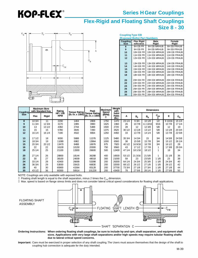
®
M-39
Series H Gear Couplings
Flex-Rigid and Floating Shaft CouplingsSize 8 - 30
Coupling Type EB(Exposed Bolts) Part Numbers
FLOATING SHAFTASSEMBLY
Ordering Instructions: When ordering floating shaft couplings, be sure to include hp and rpm, shaft separation, and equipment sh aftsizes. Applications with very large shaft separations and/or high speeds may require tubular floating shaftsdue to lateral critical speed concerns.
Impor tant: Care must be exercised in proper selection of any shaft coupling. The Users must assure themselves that the design of the shaft tocoupling hub connection is adequate for the duty intended.
NOTE: Couplings are only available with exposed bolts.➀ Floating shaft length is equal to the shaft separation, minus 2 times the CFR dimension.➁ Max. speed is based on flange stress limits and does not consider lateral critical speed considerations for floating shaft applications.
CouplingSize
Maximum Borewith Standard Key Rating
HP / 100RPM
Torque Rating(lb.-in. x 1000)
PeakTorque Rating(lb.-in. x 1000)
MaximumSpeed(RPM)
➁
WeightwithSolidHubs(lb.)
Dimensions
Flex Rigid A BF BRCFR➀
E GR
8 10 3/4 11 2230 1404 2808 1750 1470 23 1/4 9 3/4 10 1/8 1/2 9 13/16 15 1/49 11 3/4 12 3/4 3170 1995 3990 1625 1960 26 10 7/8 11 13/16 9/16 10 7/8 17 1/410 13 13 1/2 4350 2744 5488 1500 2720 28 12 12 3/8 5/8 12 1911 15 15 5780 3645 7290 1375 3520 30 1/2 13 1/8 13 1/2 5/8 13 1/8 20 3/412 16 1/4 16 1/4 7190 4532 9064 1250 4450 33 13 7/8 14 1/4 5/8 13 7/8 22 5/8
13 17 1/2 18 9030 5688 11376 1125 5480 35 3/4 14 3/4 15 3/4 14 5/8 24 5/814 18 3/4 19 11080 6982 13964 1000 6560 38 15 5/8 15 7/8 3/4 15 1/2 26 1/415 20 3/4 20 1/2 13470 8488 16976 875 7920 40 1/2 16 9/16 16 7/8 3/4 16 1/2 2816 22 22 16100 10150 20300 750 9560 43 17 1/2 17 7/8 1 17 3/8 29 3/418 25 1/4 25 21100 13300 26600 500 12400 47 1/4 18 1/16 18 1/2 1 18 34
20 27 1/4 26 28800 18144 36288 400 16500 53 1/2 21 3/16 21 5/8 1 21 1/8 3622 30 27 38100 24009 48018 300 21000 59 23 23 5/8 1 1/8 23 3824 33 1/4 28 42400 26699 53398 200 26300 64 1/4 24 3/4 25 3/8 1 1/8 24 3/4 4026 36 3/4 29 53000 33415 66830 200 32000 68 1/2 26 1/2 27 1/8 1 1/8 26 1/2 4228 40 30 65900 41564 83128 200 37700 73 3/4 27 1/8 27 3/4 1 1/8 27 1/8 4430 43 1/2 36 80300 50614 101228 200 43400 78 27 5/8 28 1/4 1 1/8 27 5/8 50
CouplingSize
Flex Rigidw/Access
MaleRigid
FemaleRigid
8 8H EB FR 8H EB MRHUB 8H EB FRHUB9 9H EB FR 9H EB MRHUB 9H EB FRHUB
10 10H EB FR 10H EB MRHUB 10H EB FRHUB11 11H EB FR 11H EB MRHUB 11H EB FRHUB12 12H EB FR 12H EB MRHUB 12H EB FRHUB
13 13H EB FR 13H EB MRHUB 13H EB FRHUB14 14H EB FR 14H EB MRHUB 14H EB FRHUB15 15H EB FR 15H EB MRHUB 15H EB FRHUB16 16H EB FR 16H EB MRHUB 16H EB FRHUB18 18H EB FR 18H EB MRHUB 18H EB FRHUB
20 20H EB FR 20H EB MRHUB 20H EB FRHUB22 22H EB FR 22H EB MRHUB 22H EB FRHUB24 24H EB FR 24H EB MRHUB 24H EB FRHUB26 26H EB FR 26H EB MRHUB 26H EB FRHUB28 28H EB FR 28H EB MRHUB 28H EB FRHUB30 30H EB FR 30H EB MRHUB 30H EB FRHUB
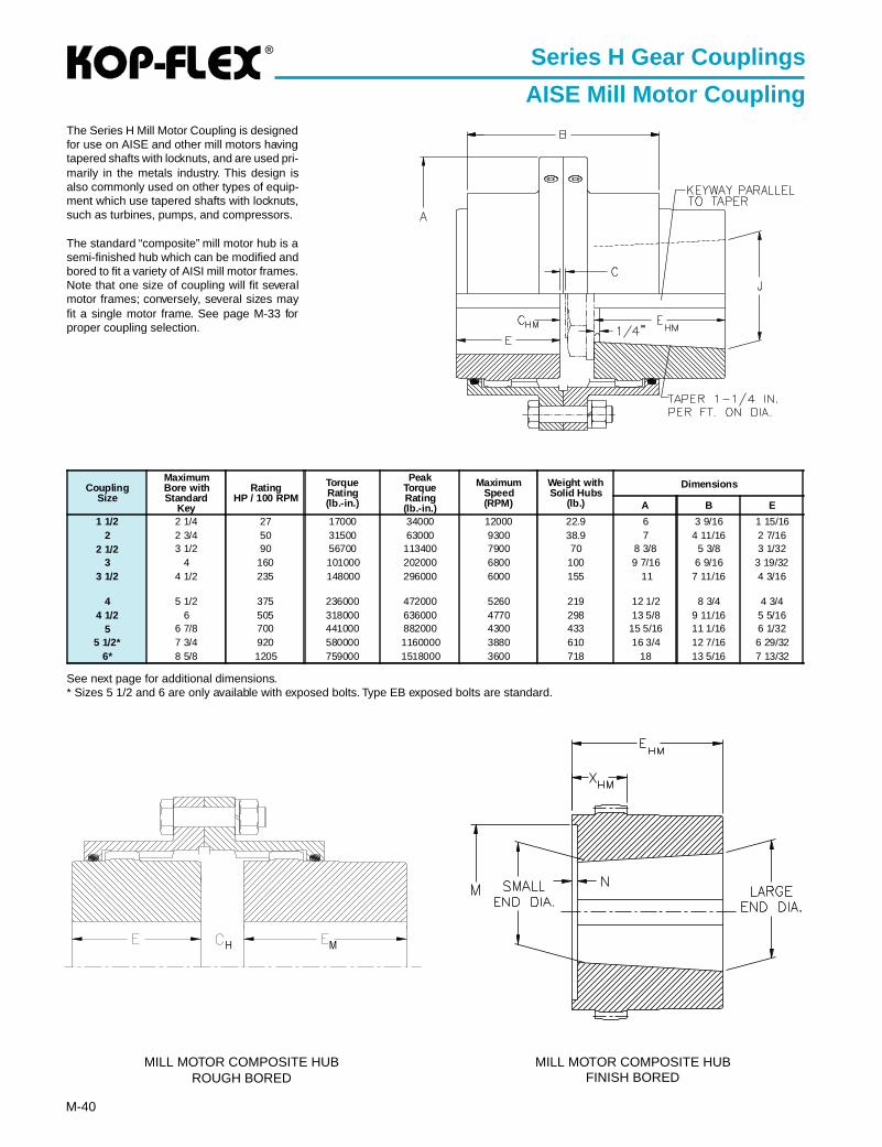
®
M-40
Series H Gear Couplings
AISE Mill Motor CouplingThe Series H Mill Motor Coupling is designedfor use on AISE and other mill motors havingtapered shafts with locknuts, and are used pri-marily in the metals industry. This design isalso commonly used on other types of equip-ment which use tapered shafts with locknuts,such as turbines, pumps, and compressors.
The standard “composite” mill motor hub is asemi-finished hub which can be modified andbored to fit a variety of AISI mill motor frames.Note that one size of coupling will fit severalmotor frames; conversely, several sizes mayfit a single motor frame. See page M-33 forproper coupling selection.
See next page for additional dimensions.* Sizes 5 1/2 and 6 are only available with exposed bolts. Type EB exposed bolts are standard.
MILL MOTOR COMPOSITE HUBROUGH BORED
MILL MOTOR COMPOSITE HUBFINISH BORED
CouplingSize
MaximumBore withStandard
Key
RatingHP / 100 RPM
TorqueRating(lb.-in.)
PeakTorqueRating(lb.-in.)
MaximumSpeed(RPM)
Weight withSolid Hubs
(lb.)
Dimensions
A B E
1 1/2 2 1/4 27 17000 34000 12000 22.9 6 3 9/16 1 15/162 2 3/4 50 31500 63000 9300 38.9 7 4 11/16 2 7/16
2 1/2 3 1/2 90 56700 113400 7900 70 8 3/8 5 3/8 3 1/323 4 160 101000 202000 6800 100 9 7/16 6 9/16 3 19/32
3 1/2 4 1/2 235 148000 296000 6000 155 11 7 11/16 4 3/16
4 5 1/2 375 236000 472000 5260 219 12 1/2 8 3/4 4 3/44 1/2 6 505 318000 636000 4770 298 13 5/8 9 11/16 5 5/16
5 6 7/8 700 441000 882000 4300 433 15 5/16 11 1/16 6 1/325 1/2* 7 3/4 920 580000 1160000 3880 610 16 3/4 12 7/16 6 29/32
6* 8 5/8 1205 759000 1518000 3600 718 18 13 5/16 7 13/32
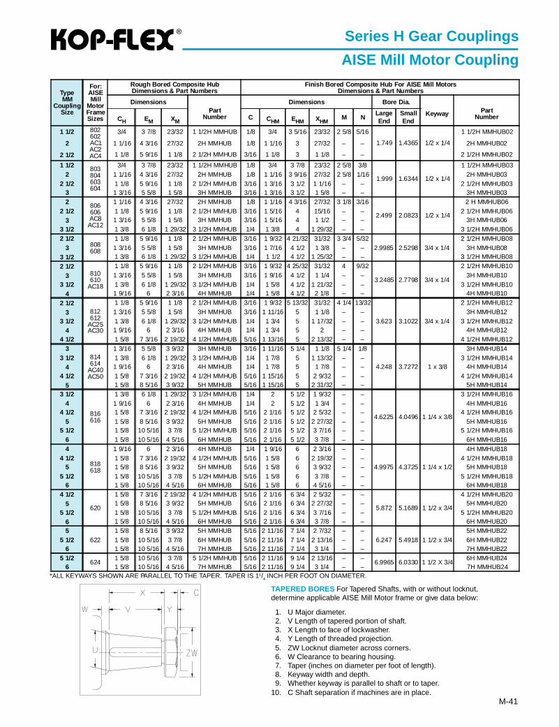
®
M-41
Series H Gear Couplings
AISE Mill Motor Coupling
*ALL KEYWAYS SHOWN ARE PARALLEL TO THE TAPER. TAPER IS 11/4 INCH PER FOOT ON DIAMETER.
TAPERED BORES For Tapered Shafts, with or without locknut,determine applicable AISE Mill Motor frame or give data below:
1. U Major diameter.2. V Length of tapered portion of shaft.3. X Length to face of lockwasher.4. Y Length of threaded projection.5. ZW Locknut diameter across corners.6. W Clearance to bearing housing.7. Taper (inches on diameter per foot of length).8. Keyway width and depth.9. Whether keyway is parallel to shaft or to taper.
10. C Shaft separation if machines are in place.
TypeMM
CouplingSize
For:AISEMill
MotorFrameSizes
Rough Bored Composite HubDimensions & Part Numbers
Finish Bored Composite Hub For AISE Mill MotorsDimensions & Part Numbers
DimensionsPart
Number
Dimensions Bore Dia.
Keyway PartNumberCH EM XM
C CHM EHM XHMM N
LargeEnd
SmallEnd
1 1/2 802602AC1AC2AC4
3/4 3 7/8 23/32 1 1/2H MMHUB 1/8 3/4 3 5/16 23/32 2 5/8 5/16
1.749 1.4365 1/2 x 1/4
1 1/2H MMHUB02
2 1 1/16 4 3/16 27/32 2H MMHUB 1/8 1 1/16 3 27/32 – – 2H MMHUB02
2 1/2 1 1/8 5 9/16 1 1/8 2 1/2H MMHUB 3/16 1 1/8 3 1 1/8 – – 2 1/2H MMHUB02
1 1/2 803804603604
3/4 3 7/8 23/32 1 1/2H MMHUB 1/8 3/4 3 7/8 23/32 2 5/8 3/8
1.999 1.6344 1/2 x 1/4
1 1/2H MMHUB032 1 1/16 4 3/16 27/32 2H MMHUB 1/8 1 1/16 3 9/16 27/32 2 5/8 1/16 2H MMHUB03
2 1/2 1 1/8 5 9/16 1 1/8 2 1/2H MMHUB 3/16 1 3/16 3 1/2 1 1/16 – – 2 1/2H MMHUB033 1 3/16 5 5/8 1 5/8 3H MMHUB 3/16 1 3/16 3 1/2 1 5/8 – – 3H MMHUB032 806
606AC8
AC12
1 1/16 4 3/16 27/32 2H MMHUB 1/8 1 1/16 4 3/16 27/32 3 1/8 3/16
2.499 2.0823 1/2 x 1/4
2 H MMHUB062 1/2 1 1/8 5 9/16 1 1/8 2 1/2H MMHUB 3/16 1 5/16 4 15/16 – – 2 1/2H MMHUB06
3 1 3/16 5 5/8 1 5/8 3H MMHUB 3/16 1 5/16 4 1 1/2 – – 3H MMHUB063 1/2 1 3/8 6 1/8 1 29/32 3 1/2H MMHUB 1/4 1 3/8 4 1 29/32 – – 3 1/2H MMHUB062 1/2
808608
1 1/8 5 9/16 1 1/8 2 1/2H MMHUB 3/16 1 9/32 4 21/32 31/32 3 3/4 5/322.9985 2.5298 3/4 x 1/4
2 1/2H MMHUB083 1 3/16 5 5/8 1 5/8 3H MMHUB 3/16 1 7/16 4 1/2 1 3/8 – – 3H MMHUB08
3 1/2 1 3/8 6 1/8 1 29/32 3 1/2H MMHUB 1/4 1 1/2 4 1/2 1 25/32 – – 3 1/2H MMHUB08
2 1/2810610
AC18
1 1/8 5 9/16 1 1/8 2 1/2H MMHUB 3/16 1 9/32 4 25/32 31/32 4 9/32
3.2485 2.7798 3/4 x 1/4
2 1/2H MMHUB10
3 1 3/16 5 5/8 1 5/8 3H MMHUB 3/16 1 9/16 4 1/2 1 1/4 – – 3H MMHUB103 1/2 1 3/8 6 1/8 1 29/32 3 1/2H MMHUB 1/4 1 5/8 4 1/2 1 21/32 – – 3 1/2H MMHUB10
4 1 9/16 6 2 3/16 4H MMHUB 1/4 1 5/8 4 1/2 2 1/8 – – 4H MMHUB10
2 1/2812612
AC25AC30
1 1/8 5 9/16 1 1/8 2 1/2H MMHUB 3/16 1 9/32 5 13/32 31/32 4 1/4 13/32
3.623 3.1022 3/4 x 1/4
2 1/2H MMHUB12
3 1 3/16 5 5/8 1 5/8 3H MMHUB 3/16 1 11/16 5 1 1/8 – – 3H MMHUB123 1/2 1 3/8 6 1/8 1 29/32 3 1/2H MMHUB 1/4 1 3/4 5 1 17/32 – – 3 1/2H MMHUB12
4 1 9/16 6 2 3/16 4H MMHUB 1/4 1 3/4 5 2 – – 4H MMHUB124 1/2 1 5/8 7 3/16 2 19/32 4 1/2H MMHUB 5/16 1 13/16 5 2 13/32 – – 4 1/2H MMHUB12
3814614
AC40AC50
1 3/16 5 5/8 3 9/32 3H MMHUB 3/16 1 11/16 5 1/4 1 1/8 5 1/4 1/8
4.248 3.7272 1 x 3/8
3H MMHUB143 1/2 1 3/8 6 1/8 1 29/32 3 1/2H MMHUB 1/4 1 7/8 5 1 13/32 – – 3 1/2H MMHUB14
4 1 9/16 6 2 3/16 4H MMHUB 1/4 1 7/8 5 1 7/8 – – 4H MMHUB144 1/2 1 5/8 7 3/16 2 19/32 4 1/2H MMHUB 5/16 1 15/16 5 2 9/32 – – 4 1/2H MMHUB14
5 1 5/8 8 5/16 3 9/32 5H MMHUB 5/16 1 15/16 5 2 31/32 – – 5H MMHUB143 1/2
816616
1 3/8 6 1/8 1 29/32 3 1/2H MMHUB 1/4 2 5 1/2 1 9/32 – –
4.6225 4.0496 1 1/4 x 3/8
3 1/2H MMHUB164 1 9/16 6 2 3/16 4H MMHUB 1/4 2 5 1/2 1 3/4 – – 4H MMHUB16
4 1/2 1 5/8 7 3/16 2 19/32 4 1/2H MMHUB 5/16 2 1/16 5 1/2 2 5/32 – – 4 1/2H MMHUB165 1 5/8 8 5/16 3 9/32 5H MMHUB 5/16 2 1/16 5 1/2 2 27/32 – – 5H MMHUB16
5 1/2 1 5/8 10 5/16 3 7/8 5 1/2H MMHUB 5/16 2 1/16 5 1/2 3 7/16 – – 5 1/2H MMHUB166 1 5/8 10 5/16 4 5/16 6H MMHUB 5/16 2 1/16 5 1/2 3 7/8 – – 6H MMHUB164
818618
1 9/16 6 2 3/16 4H MMHUB 1/4 1 9/16 6 2 3/16 – –
4.9975 4.3725 1 1/4 x 1/2
4H MMHUB184 1/2 1 5/8 7 3/16 2 19/32 4 1/2H MMHUB 5/16 1 5/8 6 2 19/32 – – 4 1/2H MMHUB18
5 1 5/8 8 5/16 3 9/32 5H MMHUB 5/16 1 5/8 6 3 9/32 – – 5H MMHUB185 1/2 1 5/8 10 5/16 3 7/8 5 1/2H MMHUB 5/16 1 5/8 6 3 7/8 – – 5 1/2H MMHUB18
6 1 5/8 10 5/16 4 5/16 6H MMHUB 5/16 1 5/8 6 4 5/16 – – 6H MMHUB184 1/2
620
1 5/8 7 3/16 2 19/32 4 1/2H MMHUB 5/16 2 1/16 6 3/4 2 5/32 – –
5.872 5.1689 1 1/2 x 3/4
4 1/2H MMHUB205 1 5/8 8 5/16 3 9/32 5H MMHUB 5/16 2 1/16 6 3/4 2 27/32 – – 5H MMHUB20
5 1/2 1 5/8 10 5/16 3 7/8 5 1/2H MMHUB 5/16 2 1/16 6 3/4 3 7/16 – – 5 1/2H MMHUB206 1 5/8 10 5/16 4 5/16 6H MMHUB 5/16 2 1/16 6 3/4 3 7/8 – – 6H MMHUB205
6221 5/8 8 5/16 3 9/32 5H MMHUB 5/16 2 11/16 7 1/4 2 7/32 – –
6.247 5.4918 1 1/2 x 3/45H MMHUB22
5 1/2 1 5/8 10 5/16 3 7/8 6H MMHUB 5/16 2 11/16 7 1/4 2 13/16 – – 6H MMHUB226 1 5/8 10 5/16 4 5/16 7H MMHUB 5/16 2 11/16 7 1/4 3 1/4 – – 7H MMHUB22
5 1/2624
1 5/8 10 5/16 3 7/8 5 1/2H MMHUB 5/16 2 11/16 9 1/4 2 13/16 – –6.9965 6.0330 1 1/2 X 3/4
6H MMHUB246 1 5/8 10 5/16 4 5/16 7H MMHUB 5/16 2 11/16 9 1/4 3 1/4 – – 7H MMHUB24
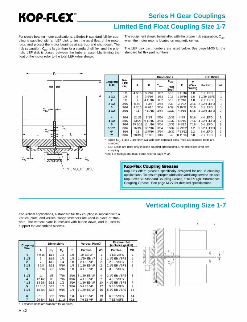
®
M-42
Series H Gear Couplings
Limited End Float Coupling Size 1-7
* Sizes 51/2, 6 and 7 are only available with exposed bolts. Type EB exposed bolts are
standard.➀ LEF Disks are used only in close coupled applications. One disk is required per
coupling.Note: For ratings and max. bores refer to page M-34.
For sleeve bearing motor applications, a Series H standard full flex cou-pling is supplied with an LEF disk to limit the axial float of the motorrotor, and protect the motor bearings at start-up and shut-down. Thehub separation, CLEF is larger than for a standard full flex, and the phe-nolic LEF disk is placed between the hubs at assembly, limiting thefloat of the motor rotor to the total LEF value shown.
Vertical Coupling Size 1-7
The equipment should be installed with the proper hub separation, CLEF
,when the motor rotor is located on magnetic center.
The LEF disk part numbers are listed below. See page M-36 for thestandard full flex part numbers.
CouplingSize
TotalLEF(in.)
Dimensions LEF Disk ➀
A B CS min.
CLEF
(HubSep.)
ET
(DiskWidth)
Part No. Wt.
1 1/8 4 9/16 3 1/16 1/32 3/16 1 11/16 1/8 1H LEFD 11 1/2 1/8 6 3 9/16 1/32 3/16 1 15/16 1/8 1 1/2H LEFD 1
2 1/8 7 4 11/16 1/32 3/16 2 7/16 1/8 2H LEFD 12 1/2 3/16 8 3/8 5 3/8 3/64 9/32 3 1/32 3/16 2 1/2H LEFD 1
3 3/16 9 7/16 6 9/16 3/64 9/32 3 19/32 3/16 3H LEFD 13 1/2 3/16 11 7 11/16 3/64 13/32 4 3/16 5/16 3 1/2H LEFD 2
4 3/16 12 1/2 8 3/4 3/64 13/32 4 3/4 5/16 4H LEFD 24 1/2 3/16 13 5/8 9 11/16 3/64 17/32 5 5/16 7/16 4 1/2H LEFD 2
5 3/16 15 5/16 11 1/16 3/64 17/32 6 1/32 7/16 5H LEFD 25 1/2* 3/16 16 3/4 12 7/16 3/64 19/32 6 29/32 1/2 5 1/2H LEFD 2
6* 3/16 18 13 5/16 3/64 19/32 7 13/32 1/2 6H LEFD 27* 3/16 20 3/4 15 3/8 1/16 3/4 8 11/16 5/8 7H LEFD 2
Kop-Flex Coupling GreasesKop-Flex offers greases specifically designed for use in couplingapplications. To ensure proper lubrication and long service life, useKop-Flex KSG Standard Coupling Grease, or KHP High PerformanceCoupling Grease. See page M-27 for detailed specifications.
For vertical applications, a standard full flex coupling is supplied with avertical plate, and vertical flange fasteners are used in place of stan-dard. The vertical plate is installed with button down, and is used tosupport the assembled sleeves.
*CouplingSize
Dimensions Vertical Plate ➀Fastener Set
(includes gasket)
A CT CC T Part No. Wt. Part No. Wt.
1 4 9/16 1/16 1/4 1/8 1H EB VP 1 1 EB VSFS 11 1/2 6 1/16 1/4 1/8 1 1/2H EB VP 1 1 1/2 EB VSFS 1
2 7 1/16 1/4 1/8 2H EB VP 2 2 EB VSFS 12 1/2 8 3/8 3/32 5/16 1/8 2 1/2H EB VP 2 2 1/2 EB VSFS 2
3 9 7/16 3/32 5/16 1/8 3H EB VP 3 3 EB VSFS 3
3 1/2 11 1/8 7/16 3/16 3 1/2H EB VP 4 3 1/2 EB VSFS 54 12 1/2 1/8 7/16 3/16 4H EB VP 7 4 EB VSFS 5
4 1/2 13 5/8 5/32 1/2 3/16 4 1/2H EB VP 10 4 1/2 EB VSFS 75 15 5/16 5/32 1/2 3/16 5H EB VP 12 5 EB VSFS 9
5 1/2 16 3/4 5/32 9/16 1/4 5 1/2H EB VP 15 5 1/2 EB VSFS 14
6 18 5/32 9/16 1/4 6H EB VP 19 6 EB VSFS 147 20 3/4 3/16 11/16 5/16 7H EB VP 25 7 EB VSFS 22
* Exposed bolts are standard for all sizes.
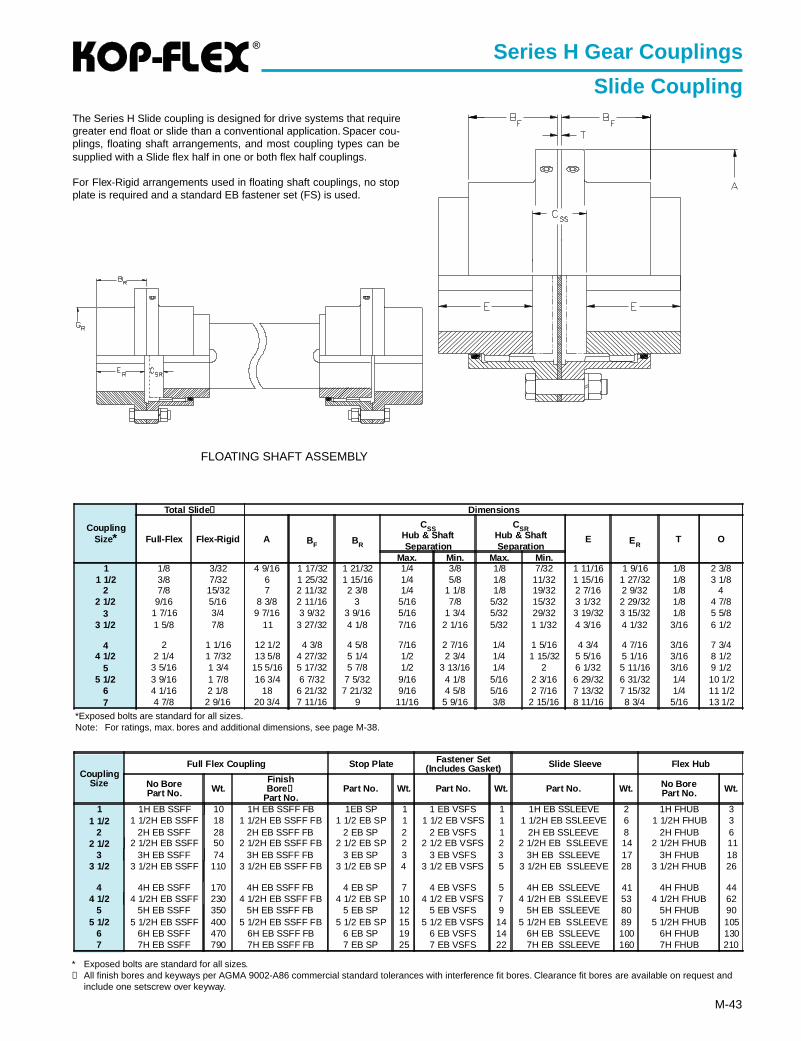
®
M-43
Series H Gear Couplings
Slide Coupling
*Exposed bolts are standard for all sizes.Note: For ratings, max. bores and additional dimensions, see page M-38.
The Series H Slide coupling is designed for drive systems that requiregreater end float or slide than a conventional application. Spacer cou-plings, floating shaft arrangements, and most coupling types can besupplied with a Slide flex half in one or both flex half couplings.
For Flex-Rigid arrangements used in floating shaft couplings, no stopplate is required and a standard EB fastener set (FS) is used.
FLOATING SHAFT ASSEMBLY
* Exposed bolts are standard for all sizes.➀ All finish bores and keyways per AGMA 9002-A86 commercial standard tolerances with interference fit bores. Clearance fit bores are available on request and
include one setscrew over keyway.
CouplingSize
Full Flex Coupling Stop Plate Fastener Set(Includes Gasket) Slide Sleeve Flex Hub
No BorePart No. Wt.
FinishBore ➀
Part No.Part No. Wt. Part No. Wt. Part No. Wt. No Bore
Part No. Wt.
1 1H EB SSFF 10 1H EB SSFF FB 1EB SP 1 1 EB VSFS 1 1H EB SSLEEVE 2 1H FHUB 31 1/2 1 1/2H EB SSFF 18 1 1/2H EB SSFF FB 1 1/2 EB SP 1 1 1/2 EB VSFS 1 1 1/2H EB SSLEEVE 6 1 1/2H FHUB 3
2 2H EB SSFF 28 2H EB SSFF FB 2 EB SP 2 2 EB VSFS 1 2H EB SSLEEVE 8 2H FHUB 62 1/2 2 1/2H EB SSFF 50 2 1/2H EB SSFF FB 2 1/2 EB SP 2 2 1/2 EB VSFS 2 2 1/2H EB SSLEEVE 14 2 1/2H FHUB 11
3 3H EB SSFF 74 3H EB SSFF FB 3 EB SP 3 3 EB VSFS 3 3H EB SSLEEVE 17 3H FHUB 183 1/2 3 1/2H EB SSFF 110 3 1/2H EB SSFF FB 3 1/2 EB SP 4 3 1/2 EB VSFS 5 3 1/2H EB SSLEEVE 28 3 1/2H FHUB 26
4 4H EB SSFF 170 4H EB SSFF FB 4 EB SP 7 4 EB VSFS 5 4H EB SSLEEVE 41 4H FHUB 444 1/2 4 1/2H EB SSFF 230 4 1/2H EB SSFF FB 4 1/2 EB SP 10 4 1/2 EB VSFS 7 4 1/2H EB SSLEEVE 53 4 1/2H FHUB 62
5 5H EB SSFF 350 5H EB SSFF FB 5 EB SP 12 5 EB VSFS 9 5H EB SSLEEVE 80 5H FHUB 905 1/2 5 1/2H EB SSFF 400 5 1/2H EB SSFF FB 5 1/2 EB SP 15 5 1/2 EB VSFS 14 5 1/2H EB SSLEEVE 89 5 1/2H FHUB 105
6 6H EB SSFF 470 6H EB SSFF FB 6 EB SP 19 6 EB VSFS 14 6H EB SSLEEVE 100 6H FHUB 1307 7H EB SSFF 790 7H EB SSFF FB 7 EB SP 25 7 EB VSFS 22 7H EB SSLEEVE 160 7H FHUB 210
CouplingSize*
Total Slide ➀ Dimensions
Full-Flex Flex-Rigid A BF BR
CSSHub & ShaftSeparation
CSRHub & ShaftSeparation
E ERT O
Max. Min. Max. Min.1 1/8 3/32 4 9/16 1 17/32 1 21/32 1/4 3/8 1/8 7/32 1 11/16 1 9/16 1/8 2 3/8
1 1/2 3/8 7/32 6 1 25/32 1 15/16 1/4 5/8 1/8 11/32 1 15/16 1 27/32 1/8 3 1/82 7/8 15/32 7 2 11/32 2 3/8 1/4 1 1/8 1/8 19/32 2 7/16 2 9/32 1/8 4
2 1/2 9/16 5/16 8 3/8 2 11/16 3 5/16 7/8 5/32 15/32 3 1/32 2 29/32 1/8 4 7/83 1 7/16 3/4 9 7/16 3 9/32 3 9/16 5/16 1 3/4 5/32 29/32 3 19/32 3 15/32 1/8 5 5/8
3 1/2 1 5/8 7/8 11 3 27/32 4 1/8 7/16 2 1/16 5/32 1 1/32 4 3/16 4 1/32 3/16 6 1/2
4 2 1 1/16 12 1/2 4 3/8 4 5/8 7/16 2 7/16 1/4 1 5/16 4 3/4 4 7/16 3/16 7 3/44 1/2 2 1/4 1 7/32 13 5/8 4 27/32 5 1/4 1/2 2 3/4 1/4 1 15/32 5 5/16 5 1/16 3/16 8 1/2
5 3 5/16 1 3/4 15 5/16 5 17/32 5 7/8 1/2 3 13/16 1/4 2 6 1/32 5 11/16 3/16 9 1/25 1/2 3 9/16 1 7/8 16 3/4 6 7/32 7 5/32 9/16 4 1/8 5/16 2 3/16 6 29/32 6 31/32 1/4 10 1/2
6 4 1/16 2 1/8 18 6 21/32 7 21/32 9/16 4 5/8 5/16 2 7/16 7 13/32 7 15/32 1/4 11 1/27 4 7/8 2 9/16 20 3/4 7 11/16 9 11/16 5 9/16 3/8 2 15/16 8 11/16 8 3/4 5/16 13 1/2
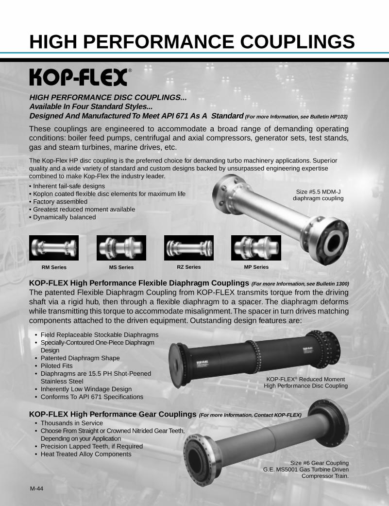
M-44
®
RM Series
These couplings are engineered to accommodate a broad range of demanding operatingconditions: boiler feed pumps, centrifugal and axial compressors, generator sets, test stands,gas and steam turbines, marine drives, etc.
The Kop-Flex HP disc coupling is the preferred choice for demanding turbo machinery applications. Superiorquality and a wide variety of standard and custom designs backed by unsurpassed engineering expertisecombined to make Kop-Flex the industry leader.
• Inherent fail-safe designs• Koplon coated flexible disc elements for maximum life• Factory assembled• Greatest reduced moment available• Dynamically balanced
KOP-FLEX High Performance Flexible Diaphragm Couplings (For more Information, see Bulletin 1300)
The patented Flexible Diaphragm Coupling from KOP-FLEX transmits torque from the drivingshaft via a rigid hub, then through a flexible diaphragm to a spacer. The diaphragm deformswhile transmitting this torque to accommodate misalignment. The spacer in turn drives matchingcomponents attached to the driven equipment. Outstanding design features are:
• Field Replaceable Stockable Diaphragms• Specially-Contoured One-Piece Diaphragm
Design• Patented Diaphragm Shape• Piloted Fits• Diaphragms are 15.5 PH Shot-Peened
Stainless Steel• Inherently Low Windage Design• Conforms To API 671 Specifications
HIGH PERFORMANCE DISC COUPLINGS...Available In Four Standard Styles...Designed And Manufactured To Meet API 671 As A Standard (For more Information, see Bulletin HP103)
MS Series RZ Series MP Series
KOP-FLEX® Reduced MomentHigh Performance Disc Coupling
Size #5.5 MDM-Jdiaphragm coupling
KOP-FLEX High Performance Gear Couplings (For more Information, Contact KOP-FLEX)
• Thousands in Service• Choose From Straight or Crowned Nitrided Gear Teeth,
Depending on your Application• Precision Lapped Teeth, if Required• Heat Treated Alloy Components
Size #6 Gear CouplingG.E. MS5001 Gas Turbine Driven
Compressor Train.
HIGH PERFORMANCE COUPLINGS
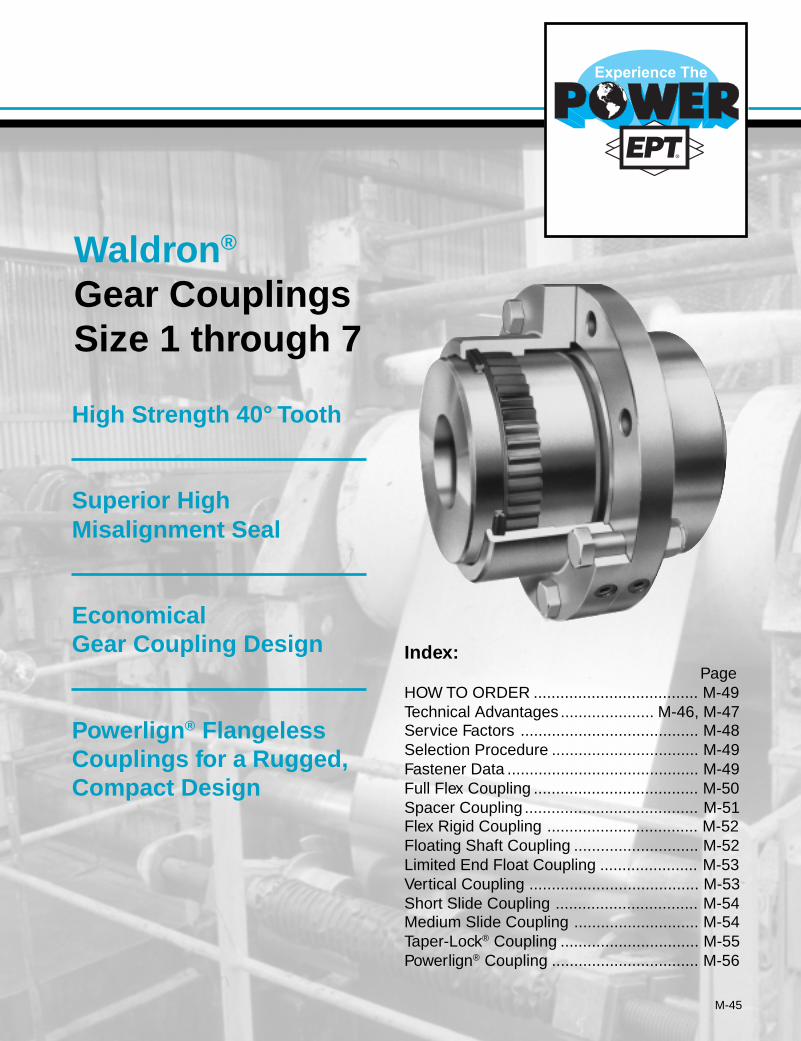
M-45
Index:Page
HOW TO ORDER ..................................... M-49Technical Advantages ..................... M-46, M-47Service Factors ........................................ M-48Selection Procedure ................................. M-49Fastener Data ........................................... M-49Full Flex Coupling ..................................... M-50Spacer Coupling ....................................... M-51Flex Rigid Coupling .................................. M-52Floating Shaft Coupling ............................ M-52Limited End Float Coupling ...................... M-53Vertical Coupling ...................................... M-53Short Slide Coupling ................................ M-54Medium Slide Coupling ............................ M-54Taper-Lock® Coupling ............................... M-55Powerlign® Coupling ................................. M-56
Waldron ®
Gear CouplingsSize 1 through 7
High Strength 40° Tooth
Superior HighMisalignment Seal
EconomicalGear Coupling Design
Powerlign ® FlangelessCouplings for a Rugged,Compact Design
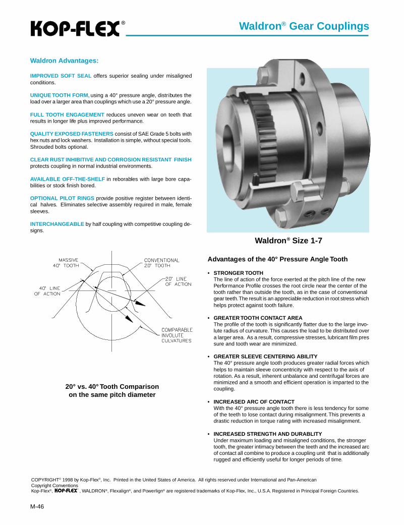
®
M-46
Advantages of the 40° Pressure Angle Tooth
• STRONGER TOOTHThe line of action of the force exerted at the pitch line of the newPerformance Profile crosses the root circle near the center of thetooth rather than outside the tooth, as in the case of conventionalgear teeth. The result is an appreciable reduction in root stress whichhelps protect against tooth failure.
• GREATER TOOTH CONTACT AREAThe profile of the tooth is significantly flatter due to the large invo-lute radius of curvature. This causes the load to be distributed overa larger area. As a result, compressive stresses, lubricant film pressure and tooth wear are minimized.
• GREATER SLEEVE CENTERING ABILITYThe 40° pressure angle tooth produces greater radial forces whichhelps to maintain sleeve concentricity with respect to the axis ofrotation. As a result, inherent unbalance and centrifugal forces areminimized and a smooth and efficient operation is imparted to thecoupling.
• INCREASED ARC OF CONTACTWith the 40° pressure angle tooth there is less tendency for someof the teeth to lose contact during misalignment. This prevents adrastic reduction in torque rating with increased misalignment.
• INCREASED STRENGTH AND DURABLITYUnder maximum loading and misaligned conditions, the strongertooth, the greater intimacy between the teeth and the increased arcof contact all combine to produce a coupling unit that is additionallyrugged and efficiently useful for longer periods of time.
Waldron Advantages:
IMPROVED SOFT SEAL offers superior sealing under misalignedconditions.
UNIQUE TOOTH FORM, using a 40° pressure angle, distributes theload over a larger area than couplings which use a 20° pressure angle.
FULL TOOTH ENGAGEMENT reduces uneven wear on teeth thatresults in longer life plus improved performance.
QUALITY EXPOSED FASTENERS consist of SAE Grade 5 bolts withhex nuts and lock washers. Installation is simple, without special tools.Shrouded bolts optional.
CLEAR RUST INHIBITIVE AND CORROSION RESISTANT FINISHprotects coupling in normal industrial environments.
AVAILABLE OFF-THE-SHELF in reborables with large bore capa-bilities or stock finish bored.
OPTIONAL PILOT RINGS provide positive register between identi-cal halves. Eliminates selective assembly required in male, femalesleeves.
INTERCHANGEABLE by half coupling with competitive coupling de-signs.
COPYRIGHT© 1998 by Kop-Flex®, Inc. Printed in the United States of America. All rights reserved under International and Pan-AmericanCopyright ConventionsKop-Flex®, , WALDRON®, Flexalign®, and Powerlign® are registered trademarks of Kop-Flex, Inc., U.S.A. Registered in Principal Foreign Countries.
Waldron ® Gear Couplings
®
20° vs. 40° Tooth Comparisonon the same pitch diameter
Waldron ® Size 1-7
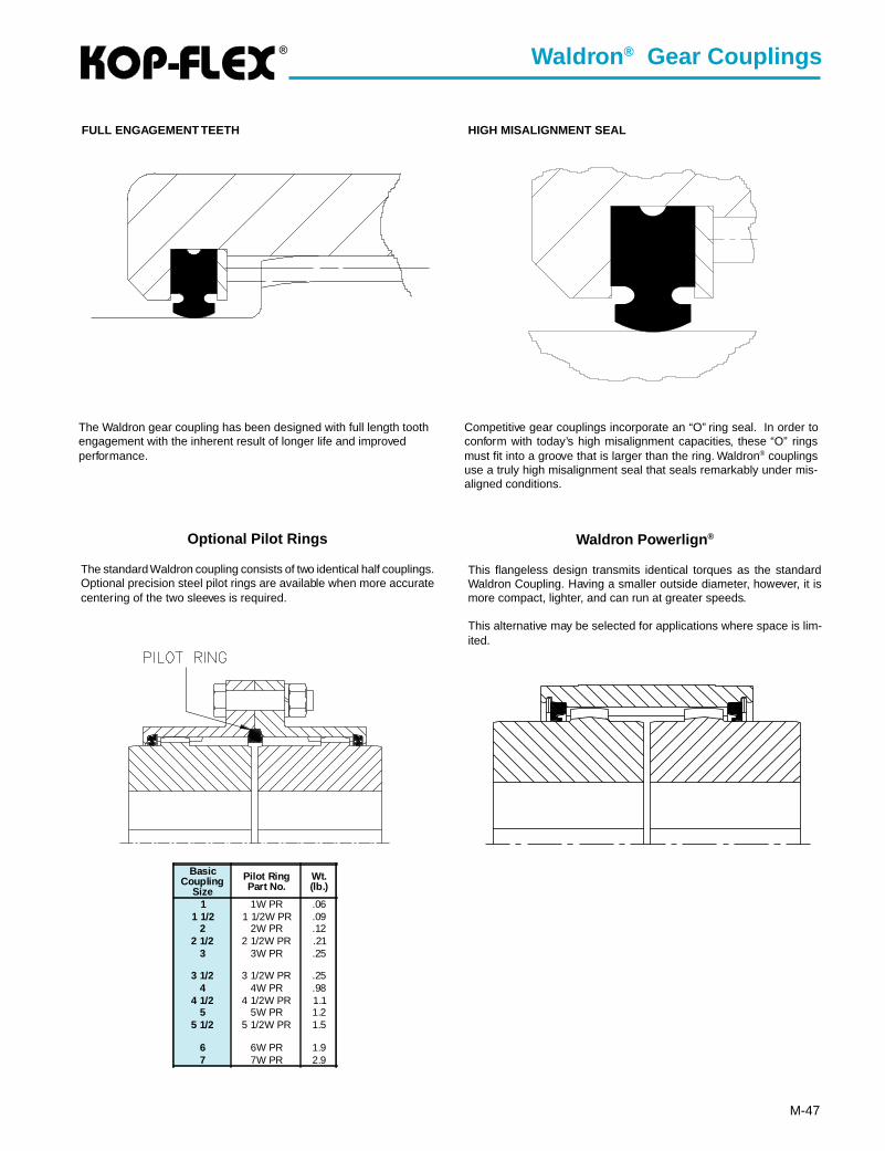
®
M-47
Competitive gear couplings incorporate an “O” ring seal. In order toconform with today’s high misalignment capacities, these “O” ringsmust fit into a groove that is larger than the ring. Waldron® couplingsuse a truly high misalignment seal that seals remarkably under mis-aligned conditions.
Waldron ® Gear Couplings
FULL ENGAGEMENT TEETH
The Waldron gear coupling has been designed with full length toothengagement with the inherent result of longer life and improvedperformance.
HIGH MISALIGNMENT SEAL
Optional Pilot Rings
The standard Waldron coupling consists of two identical half couplings.Optional precision steel pilot rings are available when more accuratecentering of the two sleeves is required.
Waldron Powerlign ®
This flangeless design transmits identical torques as the standardWaldron Coupling. Having a smaller outside diameter, however, it ismore compact, lighter, and can run at greater speeds.
This alternative may be selected for applications where space is lim-ited.
BasicCoupling
Size
Pilot RingPart No.
Wt.(lb.)
1 1W PR .061 1/2 1 1/2W PR .09
2 2W PR .122 1/2 2 1/2W PR .21
3 3W PR .25
3 1/2 3 1/2W PR .254 4W PR .98
4 1/2 4 1/2W PR 1.15 5W PR 1.2
5 1/2 5 1/2W PR 1.5
6 6W PR 1.97 7W PR 2.9
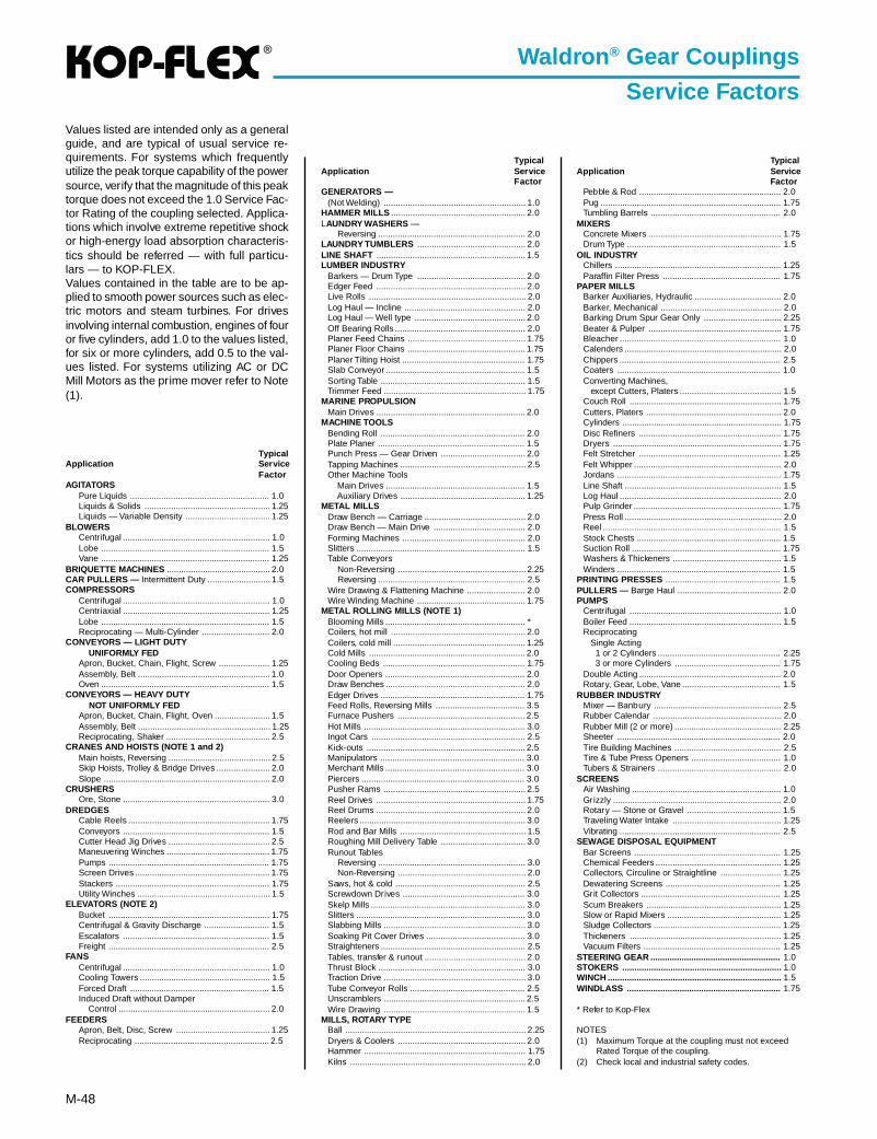
®
M-48
Waldron ® Gear Couplings
Service Factors
TypicalApplication Ser vice
FactorAGITATORS
Pure Liquids .......................................................... 1.0Liquids & Solids .................................................... 1.25Liquids — Variable Density ................................... 1.25
BLOWERSCentrifugal ............................................................. 1.0Lobe ...................................................................... 1.5Vane ...................................................................... 1.25
BRIQUETTE MACHINES ........................................... 2.0CAR PULLERS — Intermittent Duty .......................... 1.5COMPRESSORS
Centrifugal ............................................................. 1.0Centriaxial ............................................................. 1.25Lobe ...................................................................... 1.5Reciprocating — Multi-Cylinder ............................ 2.0
CONVEYORS — LIGHT DUTY UNIFORMLY FEDApron, Bucket, Chain, Flight, Screw ..................... 1.25Assembly, Belt ....................................................... 1.0Oven ...................................................................... 1.5
CONVEYORS — HEAVY DUTY NOT UNIFORMLY FEDApron, Bucket, Chain, Flight, Oven ....................... 1.5Assembly, Belt ....................................................... 1.25Reciprocating, Shaker ........................................... 2.5
CRANES AND HOISTS (NOTE 1 and 2)Main hoists, Reversing .......................................... 2.5Skip Hoists, Trolley & Bridge Drives ...................... 2.0Slope ..................................................................... 2.0
CRUSHERSOre, Stone ............................................................. 3.0
DREDGESCable Reels ........................................................... 1.75Conveyors ............................................................. 1.5Cutter Head Jig Drives .......................................... 2.5Maneuvering Winches ........................................... 1.75Pumps ................................................................... 1.75Screen Drives ........................................................ 1.75Stackers ................................................................ 1.75Utility Winches ....................................................... 1.5
ELEVATORS (NOTE 2)Bucket ................................................................... 1.75Centrifugal & Gravity Discharge ........................... 1.5Escalators ............................................................. 1.5Freight ................................................................... 2.5
FANSCentrifugal ............................................................. 1.0Cooling Towers ...................................................... 1.5Forced Draft .......................................................... 1.5Induced Draft without Damper Control ............................................................... 2.0
FEEDERSApron, Belt, Disc, Screw ....................................... 1.25Reciprocating ........................................................ 2.5
TypicalApplication Ser vice
FactorGENERATORS —
(Not Welding) ........................................................... 1.0HAMMER MILLS ........................................................ 2.0LAUNDRY WASHERS —
Reversing ............................................................. 2.0LAUNDRY TUMBLERS ............................................. 2.0LINE SHAFT .............................................................. 1.5LUMBER INDUSTRY
Barkers — Drum Type ............................................. 2.0Edger Feed .............................................................. 2.0Live Rolls ................................................................. 2.0Log Haul — Incline .................................................. 2.0Log Haul — Well type .............................................. 2.0Off Bearing Rolls ...................................................... 2.0Planer Feed Chains ................................................. 1.75Planer Floor Chains ................................................. 1.75Planer Tilting Hoist ................................................... 1.75Slab Conveyor .......................................................... 1.5Sorting Table ............................................................ 1.5Trimmer Feed ........................................................... 1.75
MARINE PROPULSIONMain Drives .............................................................. 2.0
MACHINE TOOLSBending Roll ............................................................ 2.0Plate Planer ............................................................. 1.5Punch Press — Gear Driven ................................... 2.0Tapping Machines .................................................... 2.5Other Machine Tools Main Drives .......................................................... 1.5 Auxiliary Drives .................................................... 1.25
METAL MILLSDraw Bench — Carriage .......................................... 2.0Draw Bench — Main Drive ...................................... 2.0Forming Machines ................................................... 2.0Slitters ...................................................................... 1.5Table Conveyors Non-Reversing ..................................................... 2.25 Reversing ............................................................. 2.5Wire Drawing & Flattening Machine ........................ 2.0Wire Winding Machine ............................................. 1.75
METAL ROLLING MILLS (NOTE 1)Blooming Mills .......................................................... *Coilers, hot mill ........................................................ 2.0Coilers, cold mill ....................................................... 1.25Cold Mills ................................................................. 2.0Cooling Beds ........................................................... 1.75Door Openers .......................................................... 2.0Draw Benches .......................................................... 2.0Edger Drives ............................................................ 1.75Feed Rolls, Reversing Mills ..................................... 3.5Furnace Pushers ..................................................... 2.5Hot Mills ................................................................... 3.0Ingot Cars ................................................................ 2.5Kick-outs .................................................................. 2.5Manipulators ............................................................ 3.0Merchant Mills .......................................................... 3.0Piercers .................................................................... 3.0Pusher Rams ........................................................... 2.5Reel Drives .............................................................. 1.75Reel Drums .............................................................. 2.0Reelers ..................................................................... 3.0Rod and Bar Mills .................................................... 1.5Roughing Mill Delivery Table ................................... 3.0Runout Tables Reversing ............................................................. 3.0 Non-Reversing ..................................................... 2.0Saws, hot & cold ...................................................... 2.5Screwdown Drives ................................................... 3.0Skelp Mills ................................................................ 3.0Slitters ...................................................................... 3.0Slabbing Mills ........................................................... 3.0Soaking Pit Cover Drives ......................................... 3.0Straighteners ............................................................ 2.5Tables, transfer & runout .......................................... 2.0Thrust Block ............................................................. 3.0Traction Drive ........................................................... 3.0Tube Conveyor Rolls ................................................ 2.5Unscramblers ........................................................... 2.5Wire Drawing ........................................................... 1.5
MILLS, ROTARY TYPEBall ........................................................................... 2.25Dryers & Coolers ..................................................... 2.0Hammer ................................................................... 1.75Kilns ......................................................................... 2.0
TypicalApplication Ser vice
FactorPebble & Rod ........................................................... 2.0Pug ........................................................................... 1.75Tumbling Barrels ...................................................... 2.0
MIXERSConcrete Mixers ....................................................... 1.75Drum Type ................................................................ 1.5
OIL INDUSTRYChillers ..................................................................... 1.25Paraffin Filter Press ................................................. 1.75
PAPER MILLSBarker Auxiliaries, Hydraulic .................................... 2.0Barker, Mechanical .................................................. 2.0Barking Drum Spur Gear Only ................................ 2.25Beater & Pulper ....................................................... 1.75Bleacher ................................................................... 1.0Calenders ................................................................. 2.0Chippers ................................................................... 2.5Coaters .................................................................... 1.0Converting Machines, except Cutters, Platers .......................................... 1.5Couch Roll ............................................................... 1.75Cutters, Platers ........................................................ 2.0Cylinders .................................................................. 1.75Disc Refiners ........................................................... 1.75Dryers ...................................................................... 1.75Felt Stretcher ........................................................... 1.25Felt Whipper ............................................................. 2.0Jordans .................................................................... 1.75Line Shaft ................................................................. 1.5Log Haul ................................................................... 2.0Pulp Grinder ............................................................. 1.75Press Roll ................................................................. 2.0Reel .......................................................................... 1.5Stock Chests ............................................................ 1.5Suction Roll .............................................................. 1.75Washers & Thickeners ............................................. 1.5Winders .................................................................... 1.5
PRINTING PRESSES ................................................ 1.5PULLERS — Barge Haul ........................................... 2.0PUMPS
Centrifugal ............................................................... 1.0Boiler Feed ............................................................... 1.5Reciprocating Single Acting 1 or 2 Cylinders ................................................... 2.25 3 or more Cylinders ............................................ 1.75Double Acting ........................................................... 2.0Rotary, Gear, Lobe, Vane ......................................... 1.5
RUBBER INDUSTRYMixer — Banbury ..................................................... 2.5Rubber Calendar ..................................................... 2.0Rubber Mill (2 or more) ............................................ 2.25Sheeter .................................................................... 2.0Tire Building Machines ............................................ 2.5Tire & Tube Press Openers ..................................... 1.0Tubers & Strainers ................................................... 2.0
SCREENSAir Washing .............................................................. 1.0Grizzly ...................................................................... 2.0Rotary — Stone or Gravel ....................................... 1.5Traveling Water Intake ............................................. 1.25Vibrating ................................................................... 2.5
SEWAGE DISPOSAL EQUIPMENTBar Screens ............................................................. 1.25Chemical Feeders .................................................... 1.25Collectors, Circuline or Straightline ......................... 1.25Dewatering Screens ................................................ 1.25Grit Collectors .......................................................... 1.25Scum Breakers ........................................................ 1.25Slow or Rapid Mixers ............................................... 1.25Sludge Collectors ..................................................... 1.25Thickeners ............................................................... 1.25Vacuum Filters ......................................................... 1.25
STEERING GEAR ...................................................... 1.0STOKERS .................................................................. 1.0WINCH ........................................................................ 1.5WINDLASS ................................................................ 1.75
* Refer to Kop-Flex
NOTES(1) Maximum Torque at the coupling must not exceed
Rated Torque of the coupling.(2) Check local and industrial safety codes.
Values listed are intended only as a generalguide, and are typical of usual service re-quirements. For systems which frequentlyutilize the peak torque capability of the powersource, verify that the magnitude of this peaktorque does not exceed the 1.0 Service Fac-tor Rating of the coupling selected. Applica-tions which involve extreme repetitive shockor high-energy load absorption characteris-tics should be referred — with full particu-lars — to KOP-FLEX.Values contained in the table are to be ap-plied to smooth power sources such as elec-tric motors and steam turbines. For drivesinvolving internal combustion, engines of fouror five cylinders, add 1.0 to the values listed,for six or more cylinders, add 0.5 to the val-ues listed. For systems utilizing AC or DCMill Motors as the prime mover refer to Note(1).
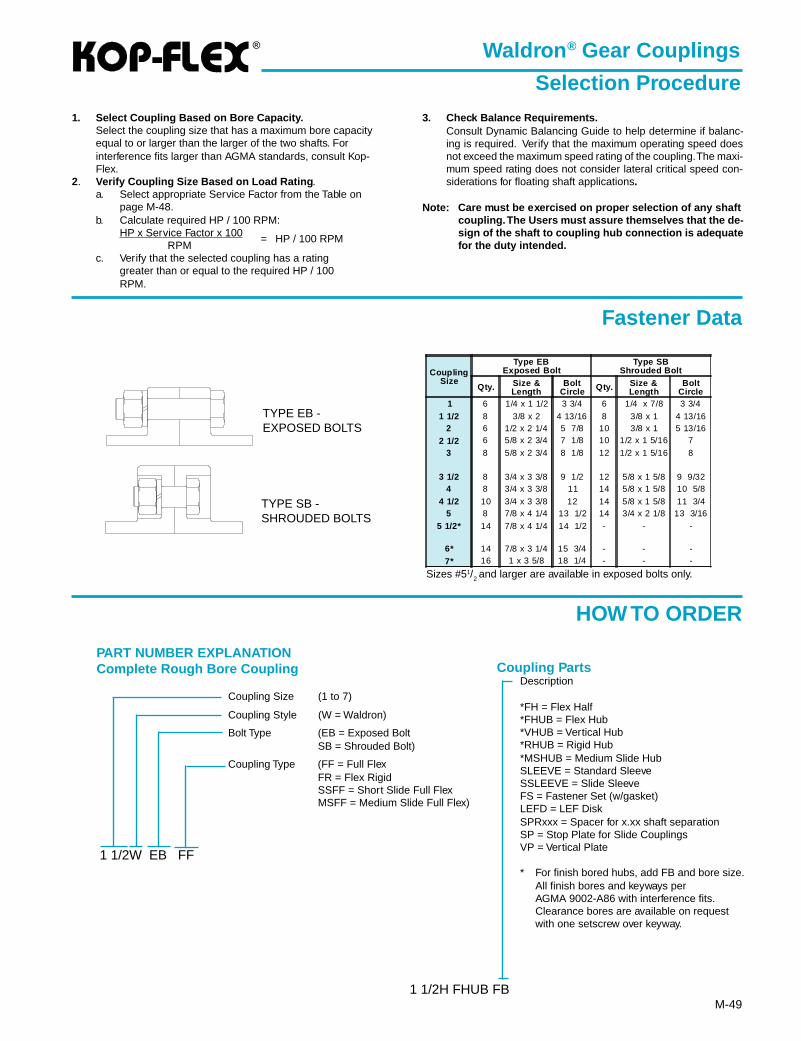
®
M-49
Waldron ® Gear Couplings
Selection Procedure1. Select Coupling Based on Bore Capacity.
Select the coupling size that has a maximum bore capacityequal to or larger than the larger of the two shafts. Forinterference fits larger than AGMA standards, consult Kop-Flex.
2. Verify Coupling Size Based on Load Rating .a. Select appropriate Service Factor from the Table on
page M-48.b. Calculate required HP / 100 RPM:
HP x Service Factor x 100RPM
= HP / 100 RPM
c. Verify that the selected coupling has a ratinggreater than or equal to the required HP / 100RPM.
3. Check Balance Requirements.Consult Dynamic Balancing Guide to help determine if balanc-ing is required. Verify that the maximum operating speed doesnot exceed the maximum speed rating of the coupling. The maxi-mum speed rating does not consider lateral critical speed con-siderations for floating shaft applications.
Note: Care must be exercised on proper selection of any shaftcoupling. The Users must assure themselves that the de-sign of the shaft to coupling hub connection is adequatefor the duty intended.
PART NUMBER EXPLANATIONComplete Rough Bore Coupling
Coupling Size (1 to 7)
Coupling Style (W = Waldron)
Bolt Type (EB = Exposed BoltSB = Shrouded Bolt)
Coupling Type (FF = Full FlexFR = Flex RigidSSFF = Short Slide Full FlexMSFF = Medium Slide Full Flex)
1 1/2W EB FF
Description
*FH = Flex Half*FHUB = Flex Hub*VHUB = Vertical Hub*RHUB = Rigid Hub*MSHUB = Medium Slide HubSLEEVE = Standard SleeveSSLEEVE = Slide SleeveFS = Fastener Set (w/gasket)LEFD = LEF DiskSPRxxx = Spacer for x.xx shaft separationSP = Stop Plate for Slide CouplingsVP = Vertical Plate
* For finish bored hubs, add FB and bore size.All finish bores and keyways perAGMA 9002-A86 with interference fits.Clearance bores are available on requestwith one setscrew over keyway.
1 1/2H FHUB FB
Coupling Parts
HOW TO ORDER
TYPE SB -SHROUDED BOLTS
TYPE EB -EXPOSED BOLTS
Sizes #51/2 and larger are available in exposed bolts only.
CouplingSize
Type EBExposed Bolt
Type SBShrouded Bolt
Qty. Size &Length
BoltCircle Qty. Size &
LengthBolt
Circle1 6 1/4 x 1 1/2 3 3/4 6 1/4 x 7/8 3 3/4
1 1/2 8 3/8 x 2 4 13/16 8 3/8 x 1 4 13/162 6 1/2 x 2 1/4 5 7/8 10 3/8 x 1 5 13/16
2 1/2 6 5/8 x 2 3/4 7 1/8 10 1/2 x 1 5/16 7
3 8 5/8 x 2 3/4 8 1/8 12 1/2 x 1 5/16 8
3 1/2 8 3/4 x 3 3/8 9 1/2 12 5/8 x 1 5/8 9 9/324 8 3/4 x 3 3/8 11 14 5/8 x 1 5/8 10 5/8
4 1/2 10 3/4 x 3 3/8 12 14 5/8 x 1 5/8 11 3/45 8 7/8 x 4 1/4 13 1/2 14 3/4 x 2 1/8 13 3/16
5 1/2* 14 7/8 x 4 1/4 14 1/2 - - -
6* 14 7/8 x 3 1/4 15 3/4 - - -
7* 16 1 x 3 5/8 18 1/4 - - -
Fastener Data
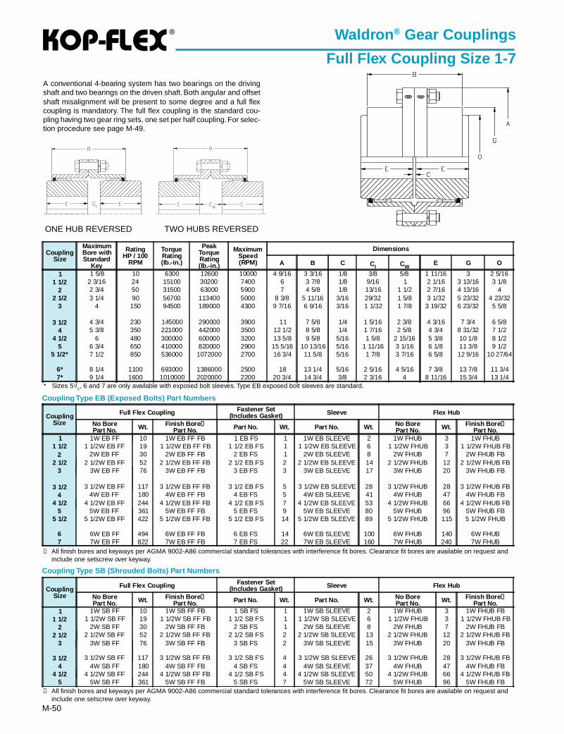
®
M-50
Waldron ® Gear Couplings
Full Flex Coupling Size 1-7
A conventional 4-bearing system has two bearings on the drivingshaft and two bearings on the driven shaft. Both angular and offsetshaft misalignment will be present to some degree and a full flexcoupling is mandatory. The full flex coupling is the standard cou-pling having two gear ring sets, one set per half coupling. For selec-tion procedure see page M-49.
* Sizes 51/2, 6 and 7 are only available with exposed bolt sleeves. Type EB exposed bolt sleeves are standard.
ONE HUB REVERSED TWO HUBS REVERSED
Coupling Type SB (Shrouded Bolts) Part Numbers
➀ All finish bores and keyways per AGMA 9002-A86 commercial standard tolerances with interference fit bores. Clearance fit bores are available on request andinclude one setscrew over keyway.
Coupling Type EB (Exposed Bolts) Part Numbers
➀ All finish bores and keyways per AGMA 9002-A86 commercial standard tolerances with interference fit bores. Clearance fit bores are available on request andinclude one setscrew over keyway.
CouplingSize
MaximumBore withStandard
Key
RatingHP / 100
RPM
TorqueRating(lb.-in.)
PeakTorqueRating(lb.-in.)
MaximumSpeed(RPM)
Dimensions
A B C CI CWE G O
1 1 5/8 10 6300 12600 10000 4 9/16 3 3/16 1/8 3/8 5/8 1 11/16 3 2 5/161 1/2 2 3/16 24 15100 30200 7400 6 3 7/8 1/8 9/16 1 2 1/16 3 13/16 3 1/8
2 2 3/4 50 31500 63000 5900 7 4 5/8 1/8 13/16 1 1/2 2 7/16 4 13/16 42 1/2 3 1/4 90 56700 113400 5000 8 3/8 5 11/16 3/16 29/32 1 5/8 3 1/32 5 23/32 4 23/32
3 4 150 94500 189000 4300 9 7/16 6 9/16 3/16 1 1/32 1 7/8 3 19/32 6 23/32 5 5/8
3 1/2 4 3/4 230 145000 290000 3900 11 7 5/8 1/4 1 5/16 2 3/8 4 3/16 7 3/4 6 5/84 5 3/8 350 221000 442000 3500 12 1/2 8 5/8 1/4 1 7/16 2 5/8 4 3/4 8 31/32 7 1/2
4 1/2 6 480 300000 600000 3200 13 5/8 9 5/8 5/16 1 5/8 2 15/16 5 3/8 10 1/8 8 1/25 6 3/4 650 410000 820000 2900 15 5/16 10 13/16 5/16 1 11/16 3 1/16 6 1/8 11 3/8 9 1/2
5 1/2* 7 1/2 850 536000 1072000 2700 16 3/4 11 5/8 5/16 1 7/8 3 7/16 6 5/8 12 9/16 10 27/64
6* 8 1/4 1100 693000 1386000 2500 18 13 1/4 5/16 2 5/16 4 5/16 7 3/8 13 7/8 11 3/47* 9 1/4 1600 1010000 2020000 2200 20 3/4 14 3/4 3/8 2 3/16 4 8 11/16 15 3/4 13 1/4
CouplingSize
Full Flex Coupling Fastener Set(Includes Gasket) Sleeve Flex Hub
No BorePart No. Wt. Finish Bore ➀
Part No. Part No. Wt. Part No. Wt. No BorePart No. Wt. Finish Bore ➀
Part No.1 1W EB FF 10 1W EB FF FB 1 EB FS 1 1W EB SLEEVE 2 1W FHUB 3 1W FHUB
1 1/2 1 1/2W EB FF 19 1 1/2W EB FF FB 1 1/2 EB FS 1 1 1/2W EB SLEEVE 6 1 1/2W FHUB 3 1 1/2W FHUB FB2 2W EB FF 30 2W EB FF FB 2 EB FS 1 2W EB SLEEVE 8 2W FHUB 7 2W FHUB FB
2 1/2 2 1/2W EB FF 52 2 1/2W EB FF FB 2 1/2 EB FS 2 2 1/2W EB SLEEVE 14 2 1/2W FHUB 12 2 1/2W FHUB FB3 3W EB FF 76 3W EB FF FB 3 EB FS 3 3W EB SLEEVE 17 3W FHUB 20 3W FHUB FB
3 1/2 3 1/2W EB FF 117 3 1/2W EB FF FB 3 1/2 EB FS 5 3 1/2W EB SLEEVE 28 3 1/2W FHUB 28 3 1/2W FHUB FB4 4W EB FF 180 4W EB FF FB 4 EB FS 5 4W EB SLEEVE 41 4W FHUB 47 4W FHUB FB
4 1/2 4 1/2W EB FF 244 4 1/2W EB FF FB 4 1/2 EB FS 7 4 1/2W EB SLEEVE 53 4 1/2W FHUB 66 4 1/2W FHUB FB5 5W EB FF 361 5W EB FF FB 5 EB FS 9 5W EB SLEEVE 80 5W FHUB 96 5W FHUB FB
5 1/2 5 1/2W EB FF 422 5 1/2W EB FF FB 5 1/2 EB FS 14 5 1/2W EB SLEEVE 89 5 1/2W FHUB 115 5 1/2W FHUB
6 6W EB FF 494 6W EB FF FB 6 EB FS 14 6W EB SLEEVE 100 6W FHUB 140 6W FHUB7 7W EB FF 822 7W EB FF FB 7 EB FS 22 7W EB SLEEVE 160 7W FHUB 240 7W FHUB
CouplingSize
Full Flex Coupling Fastener Set(Includes Gasket) Sleeve Flex Hub
No BorePart No. Wt. Finish Bore ➀
Part No. Part No. Wt. Part No. Wt. No BorePart No. Wt. Finish Bore ➀
Part No.1 1W SB FF 10 1W SB FF FB 1 SB FS 1 1W SB SLEEVE 2 1W FHUB 3 1W FHUB FB
1 1/2 1 1/2W SB FF 19 1 1/2W SB FF FB 1 1/2 SB FS 1 1 1/2W SB SLEEVE 6 1 1/2W FHUB 3 1 1/2W FHUB FB2 2W SB FF 30 2W SB FF FB 2 SB FS 1 2W SB SLEEVE 8 2W FHUB 7 2W FHUB FB
2 1/2 2 1/2W SB FF 52 2 1/2W SB FF FB 2 1/2 SB FS 2 2 1/2W SB SLEEVE 13 2 1/2W FHUB 12 2 1/2W FHUB FB3 3W SB FF 76 3W SB FF FB 3 SB FS 2 3W SB SLEEVE 15 3W FHUB 20 3W FHUB FB
3 1/2 3 1/2W SB FF 117 3 1/2W SB FF FB 3 1/2 SB FS 4 3 1/2W SB SLEEVE 26 3 1/2W FHUB 28 3 1/2W FHUB FB4 4W SB FF 180 4W SB FF FB 4 SB FS 4 4W SB SLEEVE 37 4W FHUB 47 4W FHUB FB
4 1/2 4 1/2W SB FF 244 4 1/2W SB FF FB 4 1/2 SB FS 4 4 1/2W SB SLEEVE 50 4 1/2W FHUB 66 4 1/2W FHUB FB5 5W SB FF 361 5W SB FF FB 5 SB FS 7 5W SB SLEEVE 72 5W FHUB 96 5W FHUB FB
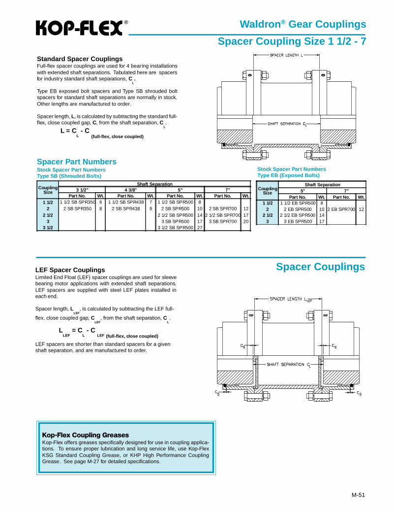
®
M-51
Standard Spacer CouplingsFull-flex spacer couplings are used for 4 bearing installationswith extended shaft separations. Tabulated here are spacersfor industry standard shaft separations, C
L.
Type EB exposed bolt spacers and Type SB shrouded boltspacers for standard shaft separations are normally in stock.Other lengths are manufactured to order.
Spacer length, L, is calculated by subtracting the standard full-flex, close coupled gap, C, from the shaft separation, C
L.
L = CL - C
(full-flex, close coupled)
Spacer Part NumbersStock Spacer Part NumbersType SB (Shrouded Bolts)
Stock Spacer Part NumbersType EB (Exposed Bolts)
LEF Spacer CouplingsLimited End Float (LEF) spacer couplings are used for sleevebearing motor applications with extended shaft separations.LEF spacers are supplied with steel LEF plates installed ineach end.
Spacer length, LLEF
, is calculated by subtracting the LEF full-
flex, close coupled gap, CLEF
, from the shaft separation, CL.
LLEF
= CL - C
LEF (full-flex, close coupled)
LEF spacers are shorter than standard spacers for a givenshaft separation, and are manufactured to order.
Waldron ® Gear Couplings
Spacer Coupling Size 1 1/2 - 7
Spacer Couplings
CouplingSize
Shaft Separation3 1/2" 4 3/8" 5" 7"
Part No. Wt. Part No. Wt. Part No. Wt. Part No. Wt.1 1/2 1 1/2 SB SPR350 6 1 1/2 SB SPR438 7 1 1/2 SB SPR500 8
2 2 SB SPR350 8 2 SB SPR438 9 2 SB SPR500 10 2 SB SPR700 122 1/2 2 1/2 SB SPR500 14 2 1/2 SB SPR700 17
3 3 SB SPR500 17 3 SB SPR700 203 1/2 3 1/2 SB SPR500 27
CouplingSize
Shaft Separation5" 7"
Part No. Wt. Part No. Wt.1 1/2 1 1/2 EB SPR500 8
2 2 EB SPR500 10 2 EB SPR700 122 1/2 2 1/2 EB SPR500 14
3 3 EB SPR500 17
Kop-Flex Coupling GreasesKop-Flex offers greases specifically designed for use in coupling applica-tions. To ensure proper lubrication and long service life, use Kop-FlexKSG Standard Coupling Grease, or KHP High Performance CouplingGrease. See page M-27 for detailed specifications.
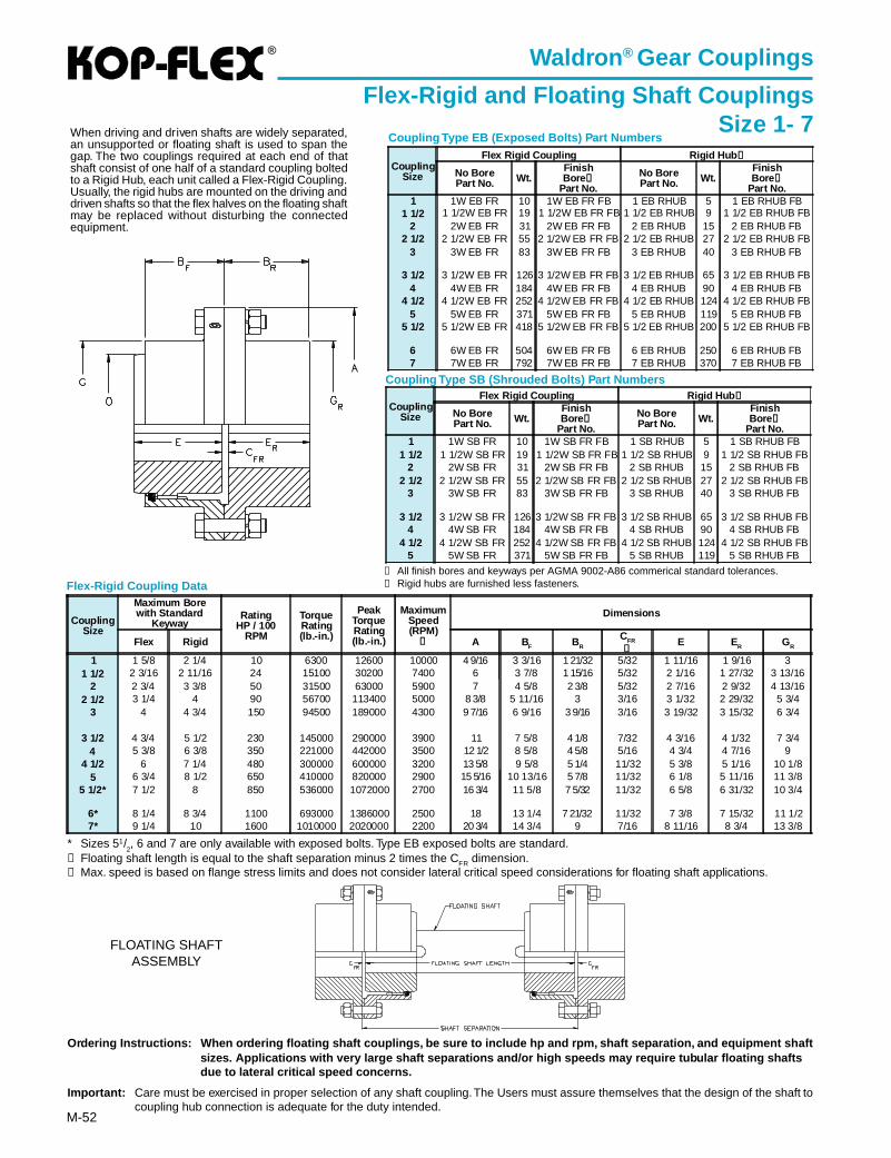
®
M-52
Coupling Type SB (Shrouded Bolts) Part Numbers
Coupling Type EB (Exposed Bolts) Part Numbers
➀ All finish bores and keyways per AGMA 9002-A86 commerical standard tolerances.➁ Rigid hubs are furnished less fasteners.
Ordering Instructions: When ordering floating shaft couplings, be sure to include hp and rpm, shaft separation, and equipment sh aftsizes. Applications with very large shaft separations and/or high speeds may require tubular floating shaftsdue to lateral critical speed concerns.
Impor tant: Care must be exercised in proper selection of any shaft coupling. The Users must assure themselves that the design of the shaft tocoupling hub connection is adequate for the duty intended.
Waldron ® Gear Couplings
Flex-Rigid and Floating Shaft CouplingsSize 1- 7
FLOATING SHAFTASSEMBLY
When driving and driven shafts are widely separated,an unsupported or floating shaft is used to span thegap. The two couplings required at each end of thatshaft consist of one half of a standard coupling boltedto a Rigid Hub, each unit called a Flex-Rigid Coupling.Usually, the rigid hubs are mounted on the driving anddriven shafts so that the flex halves on the floating shaftmay be replaced without disturbing the connectedequipment.
* Sizes 51/2, 6 and 7 are only available with exposed bolts. Type EB exposed bolts are standard.
➀ Floating shaft length is equal to the shaft separation minus 2 times the CFR dimension.➁ Max. speed is based on flange stress limits and does not consider lateral critical speed considerations for floating shaft applications.
Flex-Rigid Coupling Data
CouplingSize
Flex Rigid Coupling Rigid Hub ➁
No BorePart No. Wt.
FinishBore ➀
Part No.
No BorePart No. Wt.
FinishBore ➀
Part No.1 1W EB FR 10 1W EB FR FB 1 EB RHUB 5 1 EB RHUB FB
1 1/2 1 1/2W EB FR 19 1 1/2W EB FR FB 1 1/2 EB RHUB 9 1 1/2 EB RHUB FB2 2W EB FR 31 2W EB FR FB 2 EB RHUB 15 2 EB RHUB FB
2 1/2 2 1/2W EB FR 55 2 1/2W EB FR FB 2 1/2 EB RHUB 27 2 1/2 EB RHUB FB3 3W EB FR 83 3W EB FR FB 3 EB RHUB 40 3 EB RHUB FB
3 1/2 3 1/2W EB FR 126 3 1/2W EB FR FB 3 1/2 EB RHUB 65 3 1/2 EB RHUB FB4 4W EB FR 184 4W EB FR FB 4 EB RHUB 90 4 EB RHUB FB
4 1/2 4 1/2W EB FR 252 4 1/2W EB FR FB 4 1/2 EB RHUB 124 4 1/2 EB RHUB FB5 5W EB FR 371 5W EB FR FB 5 EB RHUB 119 5 EB RHUB FB
5 1/2 5 1/2W EB FR 418 5 1/2W EB FR FB 5 1/2 EB RHUB 200 5 1/2 EB RHUB FB
6 6W EB FR 504 6W EB FR FB 6 EB RHUB 250 6 EB RHUB FB7 7W EB FR 792 7W EB FR FB 7 EB RHUB 370 7 EB RHUB FB
CouplingSize
Flex Rigid Coupling Rigid Hub ➁
No BorePart No. Wt.
FinishBore ➀
Part No.
No BorePart No. Wt.
FinishBore ➀
Part No.1 1W SB FR 10 1W SB FR FB 1 SB RHUB 5 1 SB RHUB FB
1 1/2 1 1/2W SB FR 19 1 1/2W SB FR FB 1 1/2 SB RHUB 9 1 1/2 SB RHUB FB2 2W SB FR 31 2W SB FR FB 2 SB RHUB 15 2 SB RHUB FB
2 1/2 2 1/2W SB FR 55 2 1/2W SB FR FB 2 1/2 SB RHUB 27 2 1/2 SB RHUB FB3 3W SB FR 83 3W SB FR FB 3 SB RHUB 40 3 SB RHUB FB
3 1/2 3 1/2W SB FR 126 3 1/2W SB FR FB 3 1/2 SB RHUB 65 3 1/2 SB RHUB FB4 4W SB FR 184 4W SB FR FB 4 SB RHUB 90 4 SB RHUB FB
4 1/2 4 1/2W SB FR 252 4 1/2W SB FR FB 4 1/2 SB RHUB 124 4 1/2 SB RHUB FB5 5W SB FR 371 5W SB FR FB 5 SB RHUB 119 5 SB RHUB FB
CouplingSize
Maximum Borewith Standard
KeywayRating
HP / 100RPM
TorqueRating(lb.-in.)
PeakTorqueRating(lb.-in.)
MaximumSpeed(RPM)
➁
Dimensions
Flex Rigid A B F BR
CFR
➀E ER GR
1 1 5/8 2 1/4 10 6300 12600 10000 4 9/16 3 3/16 1 21/32 5/32 1 11/16 1 9/16 31 1/2 2 3/16 2 11/16 24 15100 30200 7400 6 3 7/8 1 15/16 5/32 2 1/16 1 27/32 3 13/16
2 2 3/4 3 3/8 50 31500 63000 5900 7 4 5/8 2 3/8 5/32 2 7/16 2 9/32 4 13/162 1/2 3 1/4 4 90 56700 113400 5000 8 3/8 5 11/16 3 3/16 3 1/32 2 29/32 5 3/4
3 4 4 3/4 150 94500 189000 4300 9 7/16 6 9/16 3 9/16 3/16 3 19/32 3 15/32 6 3/4
3 1/2 4 3/4 5 1/2 230 145000 290000 3900 11 7 5/8 4 1/8 7/32 4 3/16 4 1/32 7 3/44 5 3/8 6 3/8 350 221000 442000 3500 12 1/2 8 5/8 4 5/8 5/16 4 3/4 4 7/16 9
4 1/2 6 7 1/4 480 300000 600000 3200 13 5/8 9 5/8 5 1/4 11/32 5 3/8 5 1/16 10 1/85 6 3/4 8 1/2 650 410000 820000 2900 15 5/16 10 13/16 5 7/8 11/32 6 1/8 5 11/16 11 3/8
5 1/2* 7 1/2 8 850 536000 1072000 2700 16 3/4 11 5/8 7 5/32 11/32 6 5/8 6 31/32 10 3/4
6* 8 1/4 8 3/4 1100 693000 1386000 2500 18 13 1/4 7 21/32 11/32 7 3/8 7 15/32 11 1/27* 9 1/4 10 1600 1010000 2020000 2200 20 3/4 14 3/4 9 7/16 8 11/16 8 3/4 13 3/8
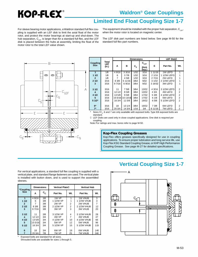
®
M-53
Waldron ® Gear Couplings
Limited End Float Coupling Size 1-7
* Sizes 51/2, 6 and 7 are only available with exposed bolts. Type EB exposed bolts are
standard.➀ LEF Disks are used only in close coupled applications. One disk is required per
coupling.Note: For ratings and max. bores refer to page M-50.
For sleeve bearing motor applications, a Waldron standard full flex cou-pling is supplied with an LEF disk to limit the axial float of the motorrotor, and protect the motor bearings at start-up and shut-down. Thehub separation, CLEF is larger than for a standard full flex, and the LEFdisk is placed between the hubs at assembly, limiting the float of themotor rotor to the total LEF value shown.
Vertical Coupling Size 1-7
The equipment should be installed with the proper hub separation, CLEF
,when the motor rotor is located on magnetic center.
The LEF disk part numbers are listed below. See page M-50 for thestandard full flex part numbers.
Kop-Flex Coupling GreasesKop-Flex offers greases specifically designed for use in couplingapplications. To ensure proper lubrication and long service life, useKop-Flex KSG Standard Coupling Grease, or KHP High PerformanceCoupling Grease. See page M-27 for detailed specifications.
For vertical applications, a standard full flex coupling is supplied with avertical plate, and standard flange fasteners are used. The vertical plateis installed with button down, and is used to support the assembledsleeves.
* Exposed bolts are standard for all sizes.Shrouded bolts are available for sizes 1 through 5.
CouplingSize
TotalLEF(in.)
Dimensions LEF Disk ➀
A B CS
CLEF
(HubSep.)
E Part No. Wt.
1 1/8 4 9/16 3 3/16 1/32 3/16 1 11/16 1W LEFD 11 1/2 1/8 6 3 7/8 1/32 3/16 2 1/16 1 1/2W LEFD 1
2 1/8 7 4 5/8 1/32 3/16 2 7/16 2W LEFD 12 1/2 3/16 8 3/8 5 11/16 3/64 9/32 3 1/32 2 1/2W LEFD 1
3 3/16 9 7/16 6 9/16 3/64 9/32 3 19/32 3W LEFD 1
3 1/2 3/16 11 7 5/8 3/64 13/32 4 3/16 3 1/2W LEFD 24 3/16 12 1/2 8 5/8 3/64 13/32 4 3/4 4W LEFD 2
4 1/2 3/16 13 5/8 9 5/8 3/64 17/32 5 3/8 4 1/2W LEFD 25 3/16 15 5/16 10 13/16 3/64 17/32 6 1/8 5W LEFD 2
5 1/2* 3/16 16 3/4 11 5/8 3/64 19/32 6 5/8 5 1/2W LEFD 2
6* 3/16 18 13 1/4 3/64 19/32 7 3/8 6W LEFD 27* 3/16 20 3/4 14 3/4 1/16 3/4 8 11/16 7W LEFD 2
*CouplingSize
Dimensions Vertical Plate ➀ Vertical Hub
A CC Part No. Wt. Part No. Wt.
1 4 9/16 3/8 1W VP 1 1W VHUB 31 1/2 6 3/8 1 1/2W VP 1 1 1/2W VHUB 3
2 7 3/8 2W VP 2 2W VHUB 72 1/2 8 3/8 3/8 2 1/2W VP 2 2 1/2W VHUB 12
3 9 7/16 3/8 3W VP 3 3W VHUB 20
3 1/2 11 3/8 3 1/2W VP 4 3 1/2W VHUB 284 12 1/2 3/4 4W VP 7 4W VHUB 47
4 1/2 13 5/8 3/4 4 1/2W VP 10 4 1/2W VHUB 665 15 5/16 3/4 5W VP 12 5W VHUB 96
5 1/2 16 3/4 3/4 5 1/2W VP 15 5 1/2W VHUB 115
6 18 3/4 6W VP 19 6W VHUB 1407 20 3/4 7/8 7W VP 25 7W VHUB 240
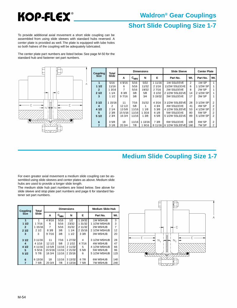
®
M-54
Waldron ® Gear Couplings
Short Slide Coupling Size 1-7To provide additional axial movement a short slide coupling can beassembled from using slide sleeves with standard hubs reversed. Acenter plate is provided as well. The plate is equipped with lube holesso both halves of the coupling will be adequately lubricated.
The center plate part numbers are listed below. See page M-50 for thestandard hub and fastener set part numbers.
For even greater axial movement a medium slide coupling can be as-sembled using slide sleeves and center plates as above. Medium slidehubs are used to provide a longer slide length.The medium slide hub part numbers are listed below. See above forslide sleeve and stop plate part numbers and page 6 for standard fas-tener set part numbers.
Medium Slide Coupling Size 1-7
CouplingSize
TotalSlide
Dimensions Slide Sleeve Center Plate
A CMIN N E Part No. Wt. Part No. Wt.
1 5/16 4 9/16 5/16 5/32 1 11/16 1W SSLEEVE 2 1W SP 11 1/2 11/16 6 5/16 11/32 2 1/16 11/2W SSLEEVE 6 1 1/2W SP 1
2 1 3/16 7 5/16 19/32 2 7/16 2W SSLEEVE 8 2W SP 12 1/2 1 1/4 8 3/8 3/8 5/8 3 1/32 2 1/2W SSLEEVE 14 2 1/2W SP 1
3 1 1/2 9 7/16 3/8 3/4 3 19/32 3W SSLEEVE 17 3W SP 1
3 1/2 1 15/16 11 7/16 31/32 4 3/16 3 1/2W SSLEEVE 28 3 1/2W SP 24 2 12 1/2 5/8 1 4 3/4 4W SSLEEVE 41 4W SP 2
4 1/2 2 1/4 13 5/8 11/16 1 1/8 5 3/8 4 1/2W SSLEEVE 53 4 1/2W SP 25 2 3/8 15 5/16 11/16 1 3/16 6 1/8 5W SSLEEVE 80 5W SP 2
5 1/2 2 3/4 16 3/4 11/16 1 3/8 6 5/8 5 1/2W SSLEEVE 89 5 1/2W SP 2
6 3 5/8 18 11/16 1 13/16 7 3/8 6W SSLEEVE 100 6W SP 27 3 1/8 20 3/4 7/8 1 9/16 8 11/16 6 1/2W SSLEEVE 160 7W SP 2
CouplingSize
TotalSlide
Dimensions Medium Slide Hub
A CMIN N E Part No. Wt.
1 1 4 9/16 5/16 1/2 1 19/32 1W MSHUB 31 1/2 1 7/16 6 5/16 23/32 1 31/32 1 1/2W MSHUB 3
2 1 15/16 7 5/16 31/32 2 11/32 2W MSHUB 72 1/2 2 1/2 8 3/8 3/8 1 1/4 2 15/16 2 1/2W MSHUB 12
3 3 9 7/16 3/8 1 1/2 3 3/8 3W MSHUB 20
3 1/2 3 11/16 11 7/16 1 27/32 4 3 1/2W MSHUB 284 4 1/16 12 1/2 5/8 2 1/32 4 7/16 4W MSHUB 47
4 1/2 4 11/16 13 5/8 11/16 2 11/32 5 4 1/2W MSHUB 665 5 5/16 15 5/16 11/16 2 21/32 5 5/8 5W MSHUB 96
5 1/2 5 7/8 16 3/4 11/16 2 15/16 6 5 1/2W MSHUB 115
6 6 13/16 18 11/16 3 13/32 6 7/8 6W MSHUB 1407 7 5/8 20 3/4 7/8 3 13/16 7 5/8 7W MSHUB 240
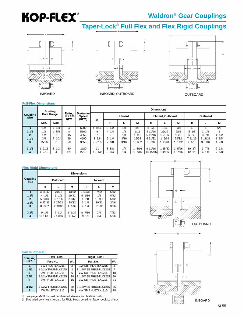
®
M-55
Waldron ® Gear Couplings
Taper-Lock ® Full Flex and Flex Rigid Couplings
CouplingSize
BushingBore Range Rating
HP / 100RPM
MaximumSpeed(RPM)
Dimensions
AInboard Inboard, Outboard Outboard
Min. Max. H L M H L M H L M
1 1/2 1 1/4 4 6900 4 9/16 3 1/2 1/8 3/8 3 3/4 7/16 3/8 4 1 5/81 1/2 1/2 1 5/8 8 5660 6 4 1/4 1/8 9/16 4 11/16 29/32 9/16 5 1/8 2 1/8 1
2 1/2 2 15 4850 7 5 1/8 13/16 5 11/16 1 21/32 13/16 6 3/8 3 7/8 1 1/22 1/2 3/4 2 1/2 29 4100 8 3/8 6 1/4 3/16 29/32 6 31/32 1 5/64 29/32 7 11/16 2 11/16 1 5/8
3 15/16 3 50 3650 9 7/16 7 3/8 3/16 1 1/32 8 7/32 1 13/64 1 1/32 9 1/16 3 1/16 1 7/8
3 1/2 1 3/16 3 1/2 80 3180 11 8 5/8 1/4 1 5/16 9 11/16 1 15/32 1 5/16 10 3/4 3 7/8 2 3/84 1 7/16 4 120 2710 12 1/2 9 3/4 1/4 1 7/16 10 15/16 1 19/32 1 7/16 12 1/8 4 1/8 2 5/8
Full-Flex Dimensions
Flex-Rigid Dimensions
CouplingSize
Flex Hubs Rigid Hubs ②
Part No. Wt. Part No. Wt.
1 1W FHUBTLX1215 2 1W SB RHUBTLX1215 31 1/2 1 1/2W FHUBTLX1215 2 1 1/2W SB RHUBTLX1215 7
2 2W FHUBTLX1215 6 2W SB RHUBTLX1215 102 1/2 2 1/2W FHUBTLX1215 10 2 1/2W SB RHUBTLX1215 20
3 3W FHUBTLX1215 15 3W SB RHUBTLX1215 31
3 1/2 3 1/2W FHUBTLX1215 20 3 1/2W SB RHUBTLX1215 554 4W FHUBTLX1215 36 4W SB RHUBTLX1215 78
Part Numbers ①①①①①
INBOARD INBOARD, OUTBOARD OUTBOARD
INBOARD
OUTBOARD
CouplingSize
Dimensions
Outboard Inboard
H L M H L M
1 3 21/32 21/32 13/32 3 13/32 7/32 5/321 1/2 4 1/2 1 1/2 19/32 4 1/16 1/2 5/32
2 5 9/16 3 1/16 27/32 4 7/8 1 3/16 5/322 1/2 6 27/32 1 27/32 29/32 6 1/8 19/32 3/16
3 8 3/32 2 3/32 1 1/32 7 1/4 21/32 3/16
3 1/2 9 1/2 2 1/2 1 9/32 8 7/16 3/4 7/324 10 11/16 2 11/16 1 1/2 9 1/2 3/4 5/16
① See page M-50 for part numbers of sleeves and fastener sets.② Shrouded bolts are standard for Rigid Hubs bored for Taper-Lock bushings.
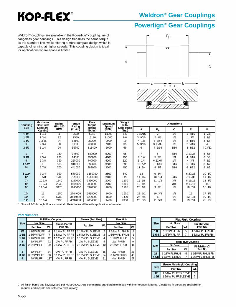
®
M-56
CouplingSize
MaximumBore withStandardKey (in.)
RatingHP / 100
RPM
TorqueRating(lb.-in.)
PeakTorqueRating(lb.-in.)
MaximumSpeed(RPM)
Weightwith
Solid Hubs(lbs.)
Dimensions
A BS C E O
1 1/8 1 1/4 4 2520 5040 14000 5.5 2 15/16 2 1/8 1 7/16 1 7/81 5/8 1 3/4 12 7560 15120 11000 9.6 3 9/16 2 1/8 1/8 1 3/4 2 1/21 1/2 2 3/16 24 15100 30200 9000 19 4 1/8 3 7/64 1/8 2 1/16 3 1/8
2 2 3/4 50 31500 63000 7200 35 5 3/16 3 15/32 1/8 2 7/16 42 1/2 3 1/4 90 56700 113400 6000 59 6 4 5/16 3/16 3 1/32 4 23/32
3 4 150 94500 189000 5200 95 7 5 3/16 3 19/32 5 5/83 1/2 4 3/4 230 14500 290000 4600 150 8 1/4 5 5/8 1/4 4 3/16 6 5/8
4 5 3/8 350 220000 440000 4200 220 9 1/4 6 21/64 1/4 4 3/4 7 1/24 1/2* 6 505 318000 636000 3500 330 10 1/2 8 1/16 5/16 5 5/16 8 1/2
5* 6 7/8 700 441000 882000 3200 450 11 3/4 8 3/8 5/16 6 1/32 9 1/2
5 1/2* 7 3/4 920 580000 1160000 2800 640 13 9 3/4 6 29/32 10 1/26* 8 5/8 1205 759000 1518000 2600 820 14 1/4 10 1/4 5/16 7 13/32 11 1/27* 10 3/8 1840 1160000 2320000 2200 1300 16 3/8 11 1/2 3/8 8 11/16 13 1/28* 10 3/4 2230 1404000 2808000 2000 1400 18 1/4 9 3/8 9 13/16 149* 11 3/4 3170 1995000 3990000 1800 1900 20 1/2 9 7/8 1/2 10 7/8 15 1/2
10* 13 1350 2744000 5488000 1600 1600 22 1/2 10 3/8 1/2 12 17 1/211* 15 5780 3645000 7290000 1500 3400 24 5/8 11 1/2 13 1/8 19 1/212* 16 1/4 7190 4532000 9064000 1400 4300 26 5/8 11 5/8 1/2 13 7/8 21 1/2
Waldron ® Gear Couplings
Powerlign ® Gear Couplings
Size
Full Flex Coupling Sleeve (Full Flex) Flex HubNo Bore Finish Bore ➀
Part No. Part No. Wt.No Bore
Part No. Wt. Part No. Wt.
1/8 1 1/8W PL FF 4 1 1/8W PL FF FB 1 1/8W PL SLEEVE 2 1 1/8W PL FHUB 11 5/8 1 5/8W PL FF 7 1 5/8W PL FF FB 1 5/8W PL SLEEVE 2 1 5/8W PL FHUB 11 1/2 1 1/2W PL FF 12 1 1/2W PL FF FB 1 1/2W PL SLEEVE 4 1 1/2W FHUB 5
2 2W PL FF 22 2W PL FF FB 2W PL SLEEVE 5 2W FHUB 92 1/2 2 1/2W PL FF 39 2 1/2W PL FF FB 2 1/2W PL SLEEVE 10 2 1/2W FHUB 15
3 3W PL FF 64 3W PL FF FB 3W PL SLEEVE 15 3W FHUB 263 1/2 3 1/2W PL FF 98 3 1/2W PL FF FB 3 1/2W PL SLEEVE 24 3 1/2W FHUB 40
4 4W PL FF 137 4W PL FF FB 4W PL SLEEVE 31 4W FHUB 57
SizeFlex-Rigid Coupling
No Bore Finish Bore ➀Part No.Part No. Wt.
1/8 1 1/8W PL FR 5 1 1/8W PL FR FB1 5/8 1 5/8W PL PR 7 1 5/8W PL FR FB
Size
Rigid Hub CouplingNo Bore Finish Bore ➀
Part No.Part No. Wt.
1/8 1 1/8W PL RHUB 5 1 1/8W PL RHUB FB1 5/8 1 5/8W PL RHUB 7 1 5/8W PL RHUB FB
SizeSleeve Flex-Rigid Coupling
Part No. Wt.
1/8 1 1/8W PL FRSLEEVE 51 5/8 1 5/8W PL FRSLEEVE 7
* Sizes 4 1/2 through 12 are non-stock. Refer to Kop-Flex with application information.
➀ All finish bores and keyways are per AGMA 9002-A86 commercial standard tolerances with interference fit bores. Clearance fit bores are available onrequest and include one setscrew over keyway.
Part Numbers
Waldron® couplings are available in the Powerlign® coupling line offlangeless gear couplings. This design transmits the same torqueas the standard line, while offering a more compact design which iscapable of running at higher speeds. This coupling design is idealfor applications where space is limited.
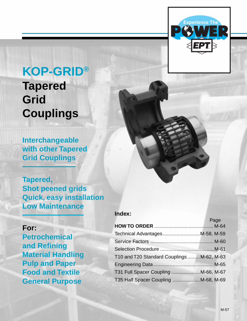
M-57
KOP-GRID®
TaperedGridCouplings
Interchangeablewith other TaperedGrid Couplings
Tapered,Shot peened gridsQuick, easy installationLow Maintenance
For:Petrochemicaland RefiningMaterial HandlingPulp and PaperFood and TextileGeneral Purpose
Index:Page
HOW TO ORDER ........................................... M-64
Technical Advantages ...........................M-58, M-59
Service Factors .............................................. M-60
Selection Procedure ....................................... M-61
T10 and T20 Standard Couplings .........M-62, M-63
Engineering Data ............................................M-65
T31 Full Spacer Coupling .....................M-66, M-67
T35 Half Spacer Coupling ....................M-68, M-69
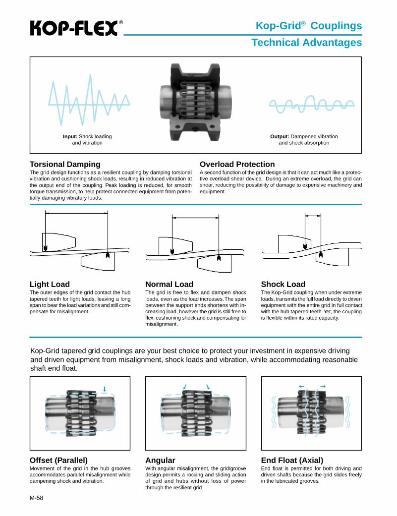
®
M-58
Kop-Grid ® Couplings
Technical Advantages
Torsional DampingThe grid design functions as a resilient coupling by damping torsionalvibration and cushioning shock loads, resulting in reduced vibration atthe output end of the coupling. Peak loading is reduced, for smoothtorque transmission, to help protect connected equipment from poten-tially damaging vibratory loads.
Light LoadThe outer edges of the grid contact the hubtapered teeth for light loads, leaving a longspan to bear the load variations and still com-pensate for misalignment.
Normal LoadThe grid is free to flex and dampen shockloads, even as the load increases. The spanbetween the support ends shortens with in-creasing load, however the grid is still free toflex, cushioning shock and compensating formisalignment.
Shock LoadThe Kop-Grid coupling when under extremeloads, transmits the full load directly to drivenequipment with the entire grid in full contactwith the hub tapered teeth. Yet, the couplingis flexible within its rated capacity.
Input: Shock loadingand vibration
Output: Dampened vibrationand shock absorption
Kop-Grid tapered grid couplings are your best choice to protect your investment in expensive drivingand driven equipment from misalignment, shock loads and vibration, while accommodating reasonableshaft end float.
Offset (Parallel)Movement of the grid in the hub groovesaccommodates parallel misalignment whiledampening shock and vibration.
AngularWith angular misalignment, the grid/groovedesign permits a rocking and sliding actionof grid and hubs without loss of powerthrough the resilient grid.
End Float (Axial)End float is permitted for both driving anddriven shafts because the grid slides freelyin the lubricated grooves.
↓↓↓↓↓ ↓↓↓↓↓ ↓↓↓↓↓ ←←←←← →→→→→
Overload ProtectionA second function of the grid design is that it can act much like a protec-tive overload shear device. During an extreme overload, the grid canshear, reducing the possibility of damage to expensive machinery andequipment.
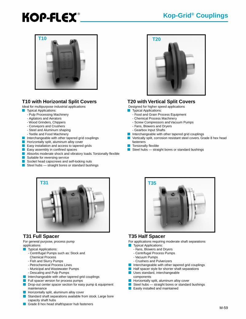
®
M-59
T10 with Horizontal Split CoversIdeal for multipurpose industrial applications■■■■■ Typical Applications:
- Pulp Processing Machinery- Agitators and Aerators- Wood Grinders, Chippers- Conveyors and Crushers- Steel and Aluminum shaping- Textile and Food Machinery
■■■■■ Interchangeable with other tapered grid couplings■■■■■ Horizontally split, aluminum alloy cover■■■■■ Easy installation and access to tapered grids■■■■■ Easy assembly in confined spaces■■■■■ Absorbs moderate shock and vibratory loads. Torsionally flexible■■■■■ Suitable for reversing service■■■■■ Socket head capscrews and self-locking nuts■■■■■ Steel hubs — straight bores or standard bushings
T35 Half SpacerFor applications requiring moderate shaft separations■■■■■ Typical Applications:
- Fans, Blowers and Dryers- Centrifugal Process Pumps- Vacuum Pumps- Crushers and Pulverizers
■■■■■ Interchangeable with other tapered grid couplings■■■■■ Half spacer style for shorter shaft separations■■■■■ Uses standard, interchangeable
components■■■■■ Horizontally split, aluminum alloy cover■■■■■ Steel hubs — straight bores or standard bushings■■■■■ Easily installed and maintained
T20 with Vertical Split Covers Designed for higher speed applications■■■■■ Typical Applications:
- Food and Grain Process Equipment- Chemical Process Machinery- Screw Compressors and Vacuum Pumps- Fans, Blowers and Dryers- Gearbox Input Shafts
■■■■■ Interchangeable with other tapered grid couplings■■■■■ Vertically split, corrosion resistant steel covers. Grade 8 hex head
fasteners■■■■■ Torsionally flexible■■■■■ Steel hubs — straight bores or standard bushings
T31 Full SpacerFor general purpose, process pumpapplications■■■■■ Typical Applications:
- Centrifugal Pumps such as: Stock and Chemical Process- Fish and Slurry Pumps- Petrochemical Process Lines- Municipal and Wastewater Pumps- Descaling and Pulp Pumps
■■■■■ Interchangeable with other tapered grid couplings■■■■■ Full spacer version for process pumps■■■■■ Drop-out center spacer section for easy pump & equipment
maintenance■■■■■ Horizontally split, aluminum alloy cover■■■■■ Standard shaft separations available from stock. Large bore
capacity shaft hubs■■■■■ Grade 8 hex head shaft/spacer hub fasteners
T31 T35
T20T10
Kop-Grid ® Couplings

®
M-60
TypicalApplication Ser vice
FactorAGITATORS
Pure Liquids .......................................................... 1.0Liquids & Solids .................................................... 1.25Liquids — Variable Density ................................... 1.25
BLOWERSCentrifugal ............................................................. 1.0Lobe ...................................................................... 1.5Vane ...................................................................... 1.25
BRIQUETTE MACHINES ........................................... 2.0CAR PULLERS — Intermittent Duty .......................... 1.5COMPRESSORS
Centrifugal ............................................................. 1.0Centriaxial ............................................................. 1.25Lobe ...................................................................... 1.5Reciprocating — Multi-Cylinder ............................ 2.0
CONVEYORS — LIGHT DUTY UNIFORMLY FEDApron, Bucket, Chain, Flight, Screw ..................... 1.25Assembly, Belt ....................................................... 1.0Oven ...................................................................... 1.5
CONVEYORS — HEAVY DUTY NOT UNIFORMLY FEDApron, Bucket, Chain, Flight, Oven ....................... 1.5Assembly, Belt ....................................................... 1.25Reciprocating, Shaker ........................................... 2.5
CRANES AND HOISTS (NOTE 1 and 2)Main hoists, Reversing .......................................... 2.5Skip Hoists, Trolley & Bridge Drives ...................... 2.0Slope ..................................................................... 2.0
CRUSHERSOre, Stone ............................................................. 3.0
DREDGESCable Reels ........................................................... 1.75Conveyors ............................................................. 1.5Cutter Head Jig Drives .......................................... 2.5Maneuvering Winches ........................................... 1.75Pumps ................................................................... 1.75Screen Drives ........................................................ 1.75Stackers ................................................................ 1.75Utility Winches ....................................................... 1.5
ELEVATORS (NOTE 2)Bucket ................................................................... 1.75Centrifugal & Gravity Discharge ........................... 1.5Escalators ............................................................. 1.5Freight ................................................................... 2.5
FANSCentrifugal ............................................................. 1.0Cooling Towers ...................................................... 1.5Forced Draft .......................................................... 1.5Induced Draft without Damper Control ............................................................... 2.0
FEEDERSApron, Belt, Disc, Screw ....................................... 1.25Reciprocating ........................................................ 2.5
TypicalApplication Ser vice
FactorGENERATORS —
(Not Welding) ........................................................... 1.0HAMMER MILLS ........................................................ 2.0LAUNDRY WASHERS —
Reversing ............................................................. 2.0LAUNDRY TUMBLERS ............................................. 2.0LINE SHAFT .............................................................. 1.5LUMBER INDUSTRY
Barkers — Drum Type ............................................. 2.0Edger Feed .............................................................. 2.0Live Rolls ................................................................. 2.0Log Haul — Incline .................................................. 2.0Log Haul — Well type .............................................. 2.0Off Bearing Rolls ...................................................... 2.0Planer Feed Chains ................................................. 1.75Planer Floor Chains ................................................. 1.75Planer Tilting Hoist ................................................... 1.75Slab Conveyor .......................................................... 1.5Sorting Table ............................................................ 1.5Trimmer Feed ........................................................... 1.75
MARINE PROPULSIONMain Drives .............................................................. 2.0
MACHINE TOOLSBending Roll ............................................................ 2.0Plate Planer ............................................................. 1.5Punch Press — Gear Driven ................................... 2.0Tapping Machines .................................................... 2.5Other Machine Tools Main Drives .......................................................... 1.5 Auxiliary Drives .................................................... 1.25
METAL MILLSDraw Bench — Carriage .......................................... 2.0Draw Bench — Main Drive ...................................... 2.0Forming Machines ................................................... 2.0Slitters ...................................................................... 1.5Table Conveyors Non-Reversing ..................................................... 2.25 Reversing ............................................................. 2.5Wire Drawing & Flattening Machine ........................ 2.0Wire Winding Machine ............................................. 1.75
METAL ROLLING MILLS (NOTE 1)Blooming Mills .......................................................... *Coilers, hot mill ........................................................ 2.0Coilers, cold mill ....................................................... 1.25Cold Mills ................................................................. 2.0Cooling Beds ........................................................... 1.75Door Openers .......................................................... 2.0Draw Benches .......................................................... 2.0Edger Drives ............................................................ 1.75Feed Rolls, Reversing Mills ..................................... 3.5Furnace Pushers ..................................................... 2.5Hot Mills ................................................................... 3.0Ingot Cars ................................................................ 2.5Kick-outs .................................................................. 2.5Manipulators ............................................................ 3.0Merchant Mills .......................................................... 3.0Piercers .................................................................... 3.0Pusher Rams ........................................................... 2.5Reel Drives .............................................................. 1.75Reel Drums .............................................................. 2.0Reelers ..................................................................... 3.0Rod and Bar Mills .................................................... 1.5Roughing Mill Delivery Table ................................... 3.0Runout Tables Reversing ............................................................. 3.0 Non-Reversing ..................................................... 2.0Saws, hot & cold ...................................................... 2.5Screwdown Drives ................................................... 3.0Skelp Mills ................................................................ 3.0Slitters ...................................................................... 3.0Slabbing Mills ........................................................... 3.0Soaking Pit Cover Drives ......................................... 3.0Straighteners ............................................................ 2.5Tables, transfer & runout .......................................... 2.0Thrust Block ............................................................. 3.0Traction Drive ........................................................... 3.0Tube Conveyor Rolls ................................................ 2.5Unscramblers ........................................................... 2.5Wire Drawing ........................................................... 1.5
MILLS, ROTARY TYPEBall ........................................................................... 2.25Dryers & Coolers ..................................................... 2.0Hammer ................................................................... 1.75Kilns ......................................................................... 2.0
TypicalApplication Ser vice
FactorPebble & Rod ........................................................... 2.0Pug ........................................................................... 1.75Tumbling Barrels ...................................................... 2.0
MIXERSConcrete Mixers ....................................................... 1.75Drum Type ................................................................ 1.5
OIL INDUSTRYChillers ..................................................................... 1.25Paraffin Filter Press ................................................. 1.75
PAPER MILLSBarker Auxiliaries, Hydraulic .................................... 2.0Barker, Mechanical .................................................. 2.0Barking Drum Spur Gear Only ................................ 2.25Beater & Pulper ....................................................... 1.75Bleacher ................................................................... 1.0Calenders ................................................................. 2.0Chippers ................................................................... 2.5Coaters .................................................................... 1.0Converting Machines, except Cutters, Platers .......................................... 1.5Couch Roll ............................................................... 1.75Cutters, Platers ........................................................ 2.0Cylinders .................................................................. 1.75Disc Refiners ........................................................... 1.75Dryers ...................................................................... 1.75Felt Stretcher ........................................................... 1.25Felt Whipper ............................................................. 2.0Jordans .................................................................... 1.75Line Shaft ................................................................. 1.5Log Haul ................................................................... 2.0Pulp Grinder ............................................................. 1.75Press Roll ................................................................. 2.0Reel .......................................................................... 1.5Stock Chests ............................................................ 1.5Suction Roll .............................................................. 1.75Washers & Thickeners ............................................. 1.5Winders .................................................................... 1.5
PRINTING PRESSES ................................................ 1.5PULLERS — Barge Haul ........................................... 2.0PUMPS
Centrifugal ............................................................... 1.0Boiler Feed ............................................................... 1.5Reciprocating Single Acting 1 or 2 Cylinders ................................................... 2.25 3 or more Cylinders ............................................ 1.75Double Acting ........................................................... 2.0Rotary, Gear, Lobe, Vane ......................................... 1.5
RUBBER INDUSTRYMixer — Banbury ..................................................... 2.5Rubber Calendar ..................................................... 2.0Rubber Mill (2 or more) ............................................ 2.25Sheeter .................................................................... 2.0Tire Building Machines ............................................ 2.5Tire & Tube Press Openers ..................................... 1.0Tubers & Strainers ................................................... 2.0
SCREENSAir Washing .............................................................. 1.0Grizzly ...................................................................... 2.0Rotary — Stone or Gravel ....................................... 1.5Traveling Water Intake ............................................. 1.25Vibrating ................................................................... 2.5
SEWAGE DISPOSAL EQUIPMENTBar Screens ............................................................. 1.25Chemical Feeders .................................................... 1.25Collectors, Circuline or Straightline ......................... 1.25Dewatering Screens ................................................ 1.25Grit Collectors .......................................................... 1.25Scum Breakers ........................................................ 1.25Slow or Rapid Mixers ............................................... 1.25Sludge Collectors ..................................................... 1.25Thickeners ............................................................... 1.25Vacuum Filters ......................................................... 1.25
STEERING GEAR ...................................................... 1.0STOKERS .................................................................. 1.0WINCH ........................................................................ 1.5WINDLASS ................................................................ 1.75
* Refer to Kop-Flex
NOTES(1) Maximum Torque at the coupling must not exceed
Rated Torque of the coupling.(2) Check local and industrial safety codes.
Values listed are intended only as a generalguide, and are typical of usual service re-quirements. For systems which frequentlyutilize the peak torque capability of the powersource, verify that the magnitude of this peaktorque does not exceed the 1.0 Service Fac-tor Rating of the coupling selected. Applica-tions which involve extreme repetitive shockor high-energy load absorption characteris-tics should be referred — with full particu-lars — to KOP-FLEX.Values contained in the table are to be ap-plied to smooth power sources such as elec-tric motors and steam turbines. For drivesinvolving internal combustion, engines of fouror five cylinders, add 1.0 to the values listed,for six or more cylinders, add 0.5 to the val-ues listed. For systems utilizing AC or DCMill Motors as the prime mover refer to Note(1).
Kop-Grid ® Couplings
Service Factors
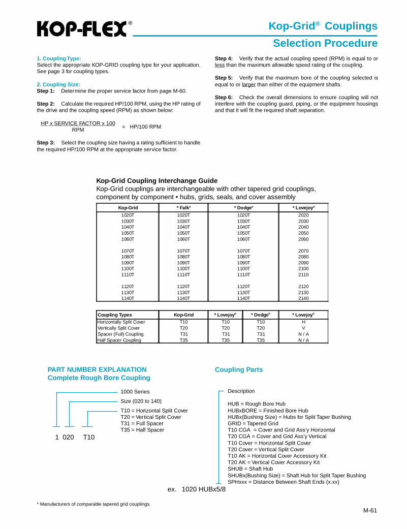
®
M-61
Kop-Grid Coupling Interchange GuideKop-Grid couplings are interchangeable with other tapered grid couplings,component by component • hubs, grids, seals, and cover assembly
Kop-Grid * Falk® * Dodge® * Lovejoy ®
1020T 1020T 1020T 20201030T 1030T 1030T 20301040T 1040T 1040T 20401050T 1050T 1050T 20501060T 1060T 1060T 2060
1070T 1070T 1070T 20701080T 1080T 1080T 20801090T 1090T 1090T 20901100T 1100T 1100T 21001110T 1110T 1110T 2110
1120T 1120T 1120T 21201130T 1130T 1130T 21301140T 1140T 1140T 2140
Coupling Types Kop-Grid * Lovejoy ® * Dodge® * Lovejoy ®
Horizontally Split Cover T10 T10 T10 HVertically Split Cover T20 T20 T20 VSpacer (Full) Coupling T31 T31 T31 N / AHalf Spacer Coupling T35 T35 T35 N / A
1. Coupling Type:Select the appropriate KOP-GRID coupling type for your application.See page 3 for coupling types.
2. Coupling Size:Step 1: Determine the proper service factor from page M-60.
Step 2: Calculate the required HP/100 RPM, using the HP rating ofthe drive and the coupling speed (RPM) as shown below:
HP x SERVICE FACTOR x 100= HP/100 RPMRPM
Step 3: Select the coupling size having a rating sufficient to handlethe required HP/100 RPM at the appropriate service factor.
Kop-Grid ® Couplings
Selection ProcedureStep 4: Verify that the actual coupling speed (RPM) is equal to orless than the maximum allowable speed rating of the coupling.
Step 5: Verify that the maximum bore of the coupling selected isequal to or larger than either of the equipment shafts.
Step 6: Check the overall dimensions to ensure coupling will notinterfere with the coupling guard, piping, or the equipment housingsand that it will fit the required shaft separation.
Description
HUB = Rough Bore HubHUBxBORE = Finished Bore HubHUBx(Bushing Size) = Hubs for Split Taper BushingGRID = Tapered GridT10 CGA = Cover and Grid Ass’y HorizontalT20 CGA = Cover and Grid Ass’y VerticalT10 Cover = Horizontal Split CoverT20 Cover = Vertical Split CoverT10 AK = Horizontal Cover Accessory KitT20 AK = Vertical Cover Accessory KitSHUB = Shaft HubSHUBx(Bushing Size) = Shaft Hub for Split Taper BushingSPHxxx = Distance Between Shaft Ends (x.xx)
PART NUMBER EXPLANATIONComplete Rough Bore Coupling
1000 Series
Size (020 to 140)
T10 = Horizontal Split CoverT20 = Vertical Split CoverT31 = Full SpacerT35 = Half Spacer
1 020 T10
Coupling Parts
ex. 1020 HUBx5/8
* Manufacturers of comparable tapered grid couplings.
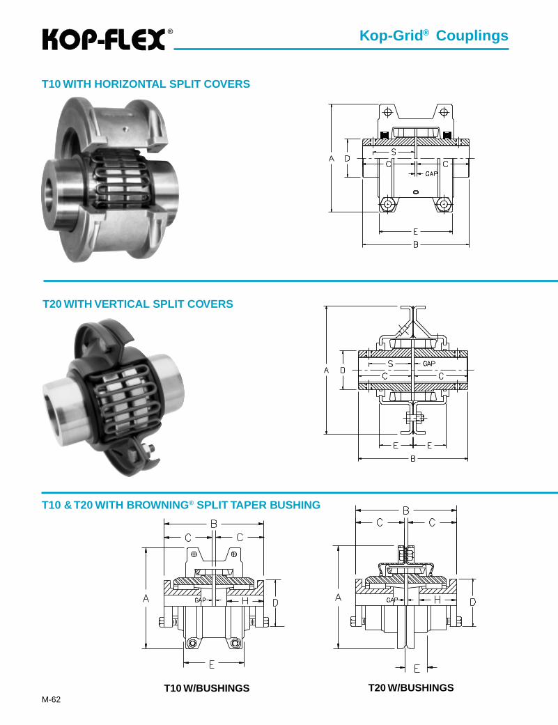
®
M-62
T20 WITH VERTICAL SPLIT COVERS
T10 WITH HORIZONTAL SPLIT COVERS
T10 & T20 WITH BROWNING ® SPLIT TAPER BUSHING
Kop-Grid ® Couplings
T10 W/BUSHINGS T20 W/BUSHINGS
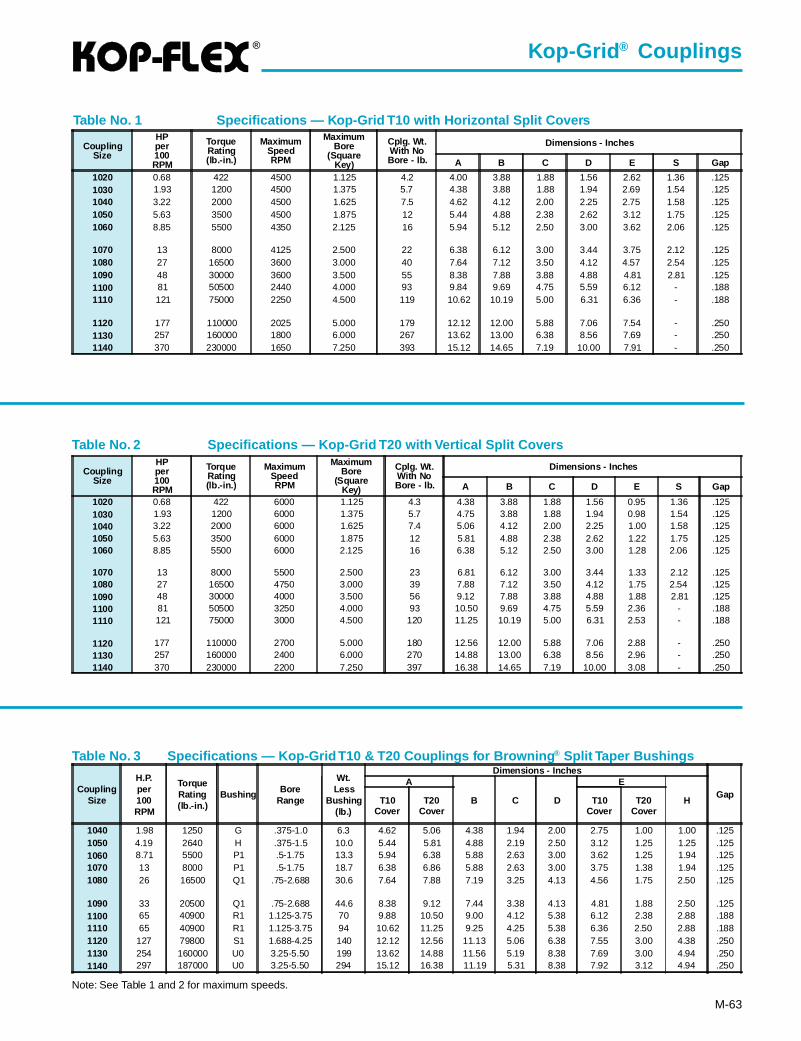
®
M-63
Table No. 2 Specifications — Kop-Grid T20 with Vertical Split Covers
Table No. 1 Specifications — Kop-Grid T10 with Horizontal Split Covers
Table No. 3 Specifications — Kop-Grid T10 & T20 Couplings for Browning ® Split Taper Bushings
Kop-Grid ® Couplings
Note: See Table 1 and 2 for maximum speeds.
CouplingSize
HPper100RPM
TorqueRating(lb.-in.)
MaximumSpeedRPM
MaximumBore
(SquareKey)
Cplg. Wt.With NoBore - lb.
Dimensions - Inches
A B C D E S Gap
1020 0.68 422 4500 1.125 4.2 4.00 3.88 1.88 1.56 2.62 1.36 .1251030 1.93 1200 4500 1.375 5.7 4.38 3.88 1.88 1.94 2.69 1.54 .1251040 3.22 2000 4500 1.625 7.5 4.62 4.12 2.00 2.25 2.75 1.58 .1251050 5.63 3500 4500 1.875 12 5.44 4.88 2.38 2.62 3.12 1.75 .1251060 8.85 5500 4350 2.125 16 5.94 5.12 2.50 3.00 3.62 2.06 .125
1070 13 8000 4125 2.500 22 6.38 6.12 3.00 3.44 3.75 2.12 .1251080 27 16500 3600 3.000 40 7.64 7.12 3.50 4.12 4.57 2.54 .1251090 48 30000 3600 3.500 55 8.38 7.88 3.88 4.88 4.81 2.81 .1251100 81 50500 2440 4.000 93 9.84 9.69 4.75 5.59 6.12 - .1881110 121 75000 2250 4.500 119 10.62 10.19 5.00 6.31 6.36 - .188
1120 177 110000 2025 5.000 179 12.12 12.00 5.88 7.06 7.54 - .2501130 257 160000 1800 6.000 267 13.62 13.00 6.38 8.56 7.69 - .2501140 370 230000 1650 7.250 393 15.12 14.65 7.19 10.00 7.91 - .250
CouplingSize
HPper100RPM
TorqueRating(lb.-in.)
MaximumSpeedRPM
MaximumBore
(SquareKey)
Cplg. Wt.With NoBore - lb.
Dimensions - Inches
A B C D E S Gap
1020 0.68 422 6000 1.125 4.3 4.38 3.88 1.88 1.56 0.95 1.36 .1251030 1.93 1200 6000 1.375 5.7 4.75 3.88 1.88 1.94 0.98 1.54 .1251040 3.22 2000 6000 1.625 7.4 5.06 4.12 2.00 2.25 1.00 1.58 .1251050 5.63 3500 6000 1.875 12 5.81 4.88 2.38 2.62 1.22 1.75 .1251060 8.85 5500 6000 2.125 16 6.38 5.12 2.50 3.00 1.28 2.06 .125
1070 13 8000 5500 2.500 23 6.81 6.12 3.00 3.44 1.33 2.12 .1251080 27 16500 4750 3.000 39 7.88 7.12 3.50 4.12 1.75 2.54 .1251090 48 30000 4000 3.500 56 9.12 7.88 3.88 4.88 1.88 2.81 .1251100 81 50500 3250 4.000 93 10.50 9.69 4.75 5.59 2.36 - .1881110 121 75000 3000 4.500 120 11.25 10.19 5.00 6.31 2.53 - .188
1120 177 110000 2700 5.000 180 12.56 12.00 5.88 7.06 2.88 - .2501130 257 160000 2400 6.000 270 14.88 13.00 6.38 8.56 2.96 - .2501140 370 230000 2200 7.250 397 16.38 14.65 7.19 10.00 3.08 - .250
CouplingSize
H.P.per100RPM
TorqueRating(lb.-in.)
Bushing BoreRange
Wt.Less
Bushing(lb.)
Dimensions - Inches
GapA
B C D
E
HT10Cover
T20Cover
T10Cover
T20Cover
1040 1.98 1250 G .375-1.0 6.3 4.62 5.06 4.38 1.94 2.00 2.75 1.00 1.00 .1251050 4.19 2640 H .375-1.5 10.0 5.44 5.81 4.88 2.19 2.50 3.12 1.25 1.25 .1251060 8.71 5500 P1 .5-1.75 13.3 5.94 6.38 5.88 2.63 3.00 3.62 1.25 1.94 .1251070 13 8000 P1 .5-1.75 18.7 6.38 6.86 5.88 2.63 3.00 3.75 1.38 1.94 .1251080 26 16500 Q1 .75-2.688 30.6 7.64 7.88 7.19 3.25 4.13 4.56 1.75 2.50 .125
1090 33 20500 Q1 .75-2.688 44.6 8.38 9.12 7.44 3.38 4.13 4.81 1.88 2.50 .1251100 65 40900 R1 1.125-3.75 70 9.88 10.50 9.00 4.12 5.38 6.12 2.38 2.88 .1881110 65 40900 R1 1.125-3.75 94 10.62 11.25 9.25 4.25 5.38 6.36 2.50 2.88 .1881120 127 79800 S1 1.688-4.25 140 12.12 12.56 11.13 5.06 6.38 7.55 3.00 4.38 .2501130 254 160000 U0 3.25-5.50 199 13.62 14.88 11.56 5.19 8.38 7.69 3.00 4.94 .2501140 297 187000 U0 3.25-5.50 294 15.12 16.38 11.19 5.31 8.38 7.92 3.12 4.94 .250
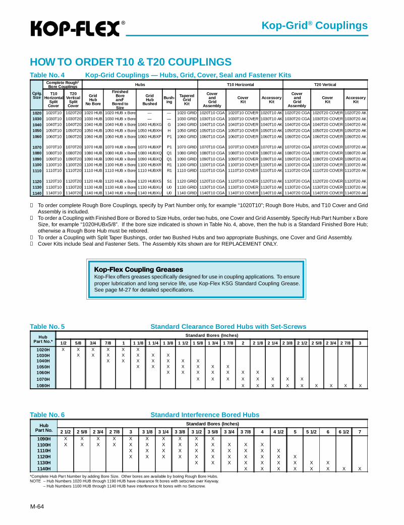
®
M-64
Kop-Grid ® Couplings
Table No. 4 Kop-Grid Couplings — Hubs, Grid, Cover, Seal and Fastener Kits
HOW TO ORDER T10 & T20 COUPLINGS
➀ To order complete Rough Bore Couplings, specify by Part Number only, for example “1020T10”; Rough Bore Hubs, and T10 Cover and GridAssembly is included.
➁ To order a Coupling with Finished Bore or Bored to Size Hubs, order two hubs, one Cover and Grid Assembly. Specify Hub Part Number x BoreSize, for example “1020HUBx5/8”. If the bore size indicated is shown in Table No. 4, above, then the hub is a Standard Finished Bore Hub;otherwise a Rough Bore Hub must be rebored.
➂ To order a Coupling with Split Taper Bushings, order two Bushed Hubs and two appropriate Bushings, one Cover and Grid Assembly.➃ Cover Kits include Seal and Fastener Sets. The Assembly Kits shown are for REPLACEMENT ONLY.
Cplg.Size
Complete Rough ➀
Bore Couplings Hubs T10 Horizontal T20 Vertical
T10Horizontal
SplitCover
T20Vertical
SplitCover
GridHub
No Bore
FinishedBoreand②
Bored toSize
GridHub
Bushed
Bush-ing
TaperedGridKit
CoverandGrid
Assembly
CoverKit
AccessoryKit
CoverandGrid
Assembly
CoverKit
AccessoryKit
1020 1020T10 1020T20 1020 HUB 1020 HUB x Bore — — 1020 GRID 1020T10 CGA 1020T10 COVER 1020T10 AK 1020T20 CGA 1020T20 COVER 1020T20 AK
1030 1030T10 1030T20 1030 HUB 1030 HUB x Bore — — 1030 GRID 1030T10 CGA 1030T10 COVER 1030T10 AK 1030T20 CGA 1030T20 COVER 1030T20 AK
1040 1040T10 1040T20 1040 HUB 1040 HUB x Bore 1040 HUBXG G 1040 GRID 1040T10 CGA 1040T10 COVER 1040T10 AK 1040T20 CGA 1040T20 COVER 1040T20 AK
1050 1050T10 1050T20 1050 HUB 1050 HUB x Bore 1050 HUBXH H 1050 GRID 1050T10 CGA 1050T10 COVER 1050T10 AK 1050T20 CGA 1050T20 COVER 1050T20 AK
1060 1060T10 1060T20 1060 HUB 1060 HUB x Bore 1060 HUBXP P1 1060 GRID 1060T10 CGA 1060T10 COVER 1060T10 AK 1060T20 CGA 1060T20 COVER 1060T20 AK
1070 1070T10 1070T20 1070 HUB 1070 HUB x Bore 1070 HUBXP P1 1070 GRID 1070T10 CGA 1070T10 COVER 1070T10 AK 1070T20 CGA 1070T20 COVER 1070T20 AK
1080 1080T10 1080T20 1080 HUB 1080 HUB x Bore 1080 HUBXQ Q1 1080 GRID 1080T10 CGA 1080T10 COVER 1080T10 AK 1080T20 CGA 1080T20 COVER 1080T20 AK
1090 1090T10 1090T20 1090 HUB 1090 HUB x Bore 1090 HUBXQ Q1 1090 GRID 1090T10 CGA 1090T10 COVER 1090T10 AK 1090T20 CGA 1090T20 COVER 1090T20 AK1100 1100T10 1100T20 1100 HUB 1100 HUB x Bore 1100 HUBXR R1 1100 GRID 1100T10 CGA 1100T10 COVER 1100T10 AK 1100T20 CGA 1100T20 COVER 1100T20 AK
1110 1110T10 1110T20 1110 HUB 1110 HUB x Bore 1110 HUBXR R1 1110 GRID 1110T10 CGA 1110T10 COVER 1110T10 AK 1110T20 CGA 1110T20 COVER 1110T20 AK
1120 1120T10 1120T20 1120 HUB 1120 HUB x Bore 1120 HUBXS S1 1120 GRID 1120T10 CGA 1120T10 COVER 1120T10 AK 1120T20 CGA 1120T20 COVER 1120T20 AK
1130 1130T10 1130T20 1130 HUB 1130 HUB x Bore 1130 HUBXU U0 1130 GRID 1130T10 CGA 1130T10 COVER 1130T10 AK 1130T20 CGA 1130T20 COVER 1130T20 AK
1140 1140T10 1140T20 1140 HUB 1140 HUB x Bore 1140 HUBXU U0 1140 GRID 1140T10 CGA 1140T10 COVER 1140T10 AK 1140T20 CGA 1140T20 COVER 1140T20 AK
Table No. 5 Standard Clearance Bored Hubs with Set-Screws
*Complete Hub Part Number by adding Bore Size. Other bores are available by boring Rough Bore Hubs.NOTE – Hub Numbers 1020 HUB through 1190 HUB have clearance fit bores with setscrew over Keyway.
– Hub Numbers 1100 HUB through 1140 HUB have interference fit bores with no Setscrew.
HubPart No.
Standard Bores (Inches)
2 1/2 2 5/8 2 3/4 2 7/8 3 3 1/8 3 1/4 3 3/8 3 1/2 3 5/8 3 3/4 3 7/8 4 4 1/2 5 5 1/2 6 6 1/2 7
1090H X X X X X X X X X X1100H X X X X X X X X X X X X X1110H X X X X X X X X X X1120H X X X X X X X X X X X1130H X X X X X X X X X1140H X X X X X X X X
HubPart No.*
Standard Bores (Inches)
1/2 5/8 3/4 7/8 1 1 1/8 1 1/4 1 3/8 1 1/2 1 5/8 1 3/4 1 7/8 2 2 1/8 2 1/4 2 3/8 2 1/2 2 5/8 2 3/4 2 7/8 3
1020H X X X X X X1030H X X X X X X X1040H X X X X X X X1050H X X X X X X X1060H X X X X X X X
1070H X X X X X X X X
1080H X X X X X X X X X
Table No. 6 Standard Interference Bored Hubs
Kop-Flex Coupling GreasesKop-Flex offers greases specifically designed for use in coupling applications. To ensureproper lubrication and long service life, use Kop-Flex KSG Standard Coupling Grease.See page M-27 for detailed specifications.
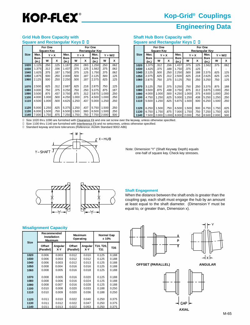
®
M-65
Shaft Hub Bore Capacity withSquare and Rectangular Keys ➀➀➀➀➀ ➁➁➁➁➁
➀ Size 1020 thru 1090 are furnished with Clearance Fit and one set screw over the keyway, unless otherwise specified.➁ Size 1100 thru 1140 are furnished with Interference Fit and no setscrews, unless otherwise specified.➂ Standard keyway and bore tolerances (Reference: AGMA Standard 9002-A86)
Grid Hub Bore Capacity withSquare and Rectangular Keys ➀➀➀➀➀ ➁➁➁➁➁
Misalignment Capacity
Shaft EngagementWhen the distance between the shaft ends is greater than thecoupling gap, each shaft must engage the hub by an amountat least equal to the shaft diameter. (Dimension Y must beequal to, or greater than, Dimension x).
OFFSET (PARALLEL) ANGULAR
AXIAL
Note: Dimension “Y” (Shaft Keyway Depth) equalsone-half of square key. Check key stresses.
Kop-Grid ® Couplings
Engineering Data
Size
For OneSquare Key
For OneRectangular Key
Max.Bore(in.)
Y = X Max.Bore(in.)
Y = X Max.Bore(in.)
Y = W/2
W X W X W X
1020 1.125 .250 .125 1.187 .250 .093 1.250 .250 .0621030 1.375 .312 .156 1.437 .375 .125 1.562 .375 .0621040 1.625 .375 .187 1.750 .375 .125 1.750 .375 .0621050 1.875 .500 .250 2.000 .500 .187 2.125 .500 .1251060 2.125 .500 .250 2.250 .500 .187 2.375 .625 .125
1070 2.500 .625 .312 2.687 .625 .218 2.875 .750 .1251080 3.000 .750 .375 3.250 .750 .250 3.375 .875 .1871090 3.500 .875 .437 3.750 .875 .312 3.875 1.000 .2501100 4.000 1.000 .500 4.250 1.000 .375 4.500 1.000 .2501110 4.500 1.000 .500 4.625 1.250 .437 5.000 1.250 .250
1120 5.000 1.250 .625 5.375 1.250 .437 5.750 1.500 .2501130 6.000 1.500 .750 6.500 1.500 .500 6.500 1.500 .2501140 7.000 1.750 .875 7.250 1.750 .750 7.750 2.000 .500
Size
For OneSquare Key
For OneRectangular Key
Max.Bore(in.)
Y = X Max.Bore(in.)
Y = X Max.Bore(in.)
Y = W/2
W X W X W X
1020 1.375 .312 .156 1.437 .375 .125 1.562 .375 .0621030 1.625 .375 .188 1.750 .375 .125 - - -1040 2.125 .500 .250 2.250 .500 .188 2.375 .625 .1251050 2.375 .625 .312 2.500 .625 .218 2.625 .625 .1251060 2.875 .750 .375 3.125 .750 .250 3.250 .750 .125
1070 3.125 .750 .375 3.250 .750 .250 3.375 .875 .1881080 3.500 .875 .438 3.750 .875 .312 3.875 1.000 .2501090 4.000 1.000 .500 4.250 1.000 .375 4.500 1.000 .2501100 4.750 1.250 .625 5.000 1.250 .438 5.250 1.250 .2501110 5.500 1.250 .625 5.875 1.500 .500 6.250 1.500 .250
1120 6.250 1.500 .750 6.500 1.500 .500 6.750 1.750 .6251130 6.750 1.750 .875 7.000 1.750 .750 7.250 1.750 .6251140 7.500 2.000 1.000 8.000 2.000 .750 8.500 2.000 .500
Size
RecommendedInstallationMaximum
MaximumOperating
Normal Gap± 10%
Offset(Parallel)
AngularX-Y
Offset(Parallel)
AngularX-Y
T10, T20,T31 T35
1020 0.006 0.003 0.012 0.010 0.125 0.1881030 0.006 0.003 0.012 0.012 0.125 0.1881040 0.006 0.003 0.012 0.013 0.125 0.1881050 0.008 0.004 0.016 0.016 0.125 0.1881060 0.008 0.005 0.016 0.018 0.125 0.188
1070 0.008 0.005 0.016 0.020 0.125 0.1881080 0.008 0.006 0.016 0.024 0.125 0.1881090 0.008 0.007 0.016 0.028 0.125 0.1881100 0.010 0.008 0.020 0.033 0.188 0.2501110 0.010 0.009 0.020 0.036 0.188 0.250
1120 0.011 0.010 0.022 0.040 0.250 0.3751130 0.011 0.012 0.022 0.047 0.250 0.3751140 0.011 0.013 0.022 0.053 0.250 0.375
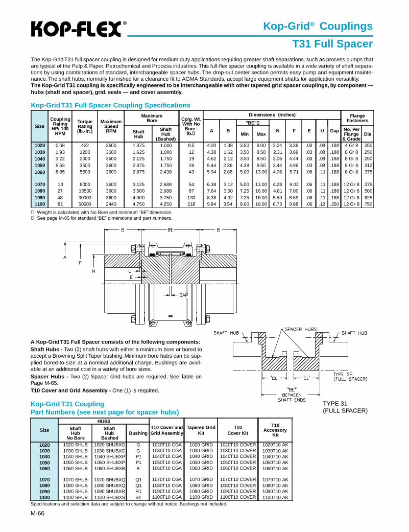
®
M-66
Kop-Grid ® Couplings
T31 Full Spacer
Kop-Grid T31 Full Spacer Coupling Specifications
Specifications and selection data are subject to change without notice. Bushings not included.
➀ Weight is calculated with No Bore and minimum “BE” dimension.➁ See page M-65 for standard “BE” dimensions and part numbers.
The Kop-Grid T31 full spacer coupling is designed for medium duty applications requiring greater shaft separations, such as process pumps thatare typical of the Pulp & Paper, Petrochemical and Process industries. This full-flex spacer coupling is available in a wide variety of shaft separa-tions by using combinations of standard, interchangeable spacer hubs. The drop-out center section permits easy pump and equipment mainte-nance. The shaft hubs, normally furnished for a clearance fit to AGMA Standards, accept large equipment shafts for application versatility.The Kop-Grid T31 coupling is specifically engineered to be interchangeable with other tapered grid spacer couplings, by compone nt —hubs (shaft and spacer), grid, seals — and cover assembly.
Kop-Grid T31 CouplingPart Numbers (see next page for spacer hubs)
A Kop-Grid T31 Full Spacer consists of the following components:Shaft Hubs - Two (2) shaft hubs with either a minimum bore or bored toaccept a Browning Split Taper bushing. Minimum bore hubs can be sup-plied bored-to-size at a nominal additional charge. Bushings are avail-able at an additional cost in a variety of bore sizes.Spacer Hubs - Two (2) Spacer Grid hubs are required. See Table onPage M-65.T10 Cover and Grid Assembly - One (1) is required.
Size
HUBST10 Cover andGrid Assembly
Tapered GridKit
T10Cover Kit
T10Accessory
KitShaftHub
No Bore
ShaftHub
BushedBushing
1020 1020 SHUB 1020 SHUBXG G 1020T10 CGA 1020 GRID 1020T10 COVER 1020T10 AK1030 1030 SHUB 1030 SHUBXG G 1030T10 CGA 1030 GRID 1030T10 COVER 1030T10 AK1040 1040 SHUB 1040 SHUBXP P1 1040T10 CGA 1040 GRID 1040T10 COVER 1040T10 AK1050 1050 SHUB 1050 SHUBXP P1 1050T10 CGA 1050 GRID 1050T10 COVER 1050T10 AK1060 1060 SHUB 1060 SHUBXB B 1060T10 CGA 1060 GRID 1060T10 COVER 1060T10 AK
1070 1070 SHUB 1070 SHUBXQ Q1 1070T10 CGA 1070 GRID 1070T10 COVER 1070T10 AK1080 1080 SHUB 1080 SHUBXQ Q1 1080T10 CGA 1080 GRID 1080T10 COVER 1080T10 AK1090 1090 SHUB 1090 SHUBXR R1 1090T10 CGA 1090 GRID 1090T10 COVER 1090T10 AK1100 1100 SHUB 1100 SHUBXS S1 1100T10 CGA 1100 GRID 1100T10 COVER 1100T10 AK
TYPE 31(FULL SPACER)
Size
CouplingRating
HP/ 100RPM
TorqueRating(lb.-in.)
MaximumSpeedRPM
MaximumBore Cplg. Wt.
With NoBore -lb.①
Dimensions (Inches) FlangeFasteners
A B
"BE" ②
N F E U GapShaftHub
ShaftHub
(Bushed)Min Max
No. PerFlange
& GradeDia
1020 0.68 422 3600 1.375 1.000 8.5 4.00 1.38 3.50 8.00 2.04 3.38 .03 .08 .188 4 Gr 8 .2501030 1.93 1200 3600 1.625 1.000 12 4.38 1.62 3.50 8.50 2.31 3.69 .03 .08 .188 8 Gr 8 .2501040 3.22 2000 3600 2.125 1.750 19 4.62 2.12 3.50 8.50 3.06 4.44 .03 .08 .188 8 Gr 8 .2501050 5.63 3500 3600 2.375 1.750 28 5.44 2.36 4.38 8.50 3.44 4.96 .03 .08 .188 8 Gr 8 .3121060 8.85 5500 3600 2.875 2.438 43 5.94 2.88 5.00 13.00 4.06 5.71 .06 .11 .188 8 Gr 8 .375
1070 13 8000 3600 3.125 2.688 54 6.38 3.12 5.00 13.00 4.28 6.02 .06 .11 .188 12 Gr 8 .3751080 27 16500 3600 3.500 2.688 87 7.64 3.50 7.25 16.00 4.81 7.00 .06 .11 .188 12 Gr 8 .5001090 48 30000 3600 4.000 3.750 133 8.38 4.02 7.25 16.00 5.59 8.69 .06 .11 .188 12 Gr 8 .6251100 81 50500 2440 4.750 4.250 218 9.84 3.54 8.00 16.00 6.73 9.88 .06 .12 .250 12 Gr 8 .750
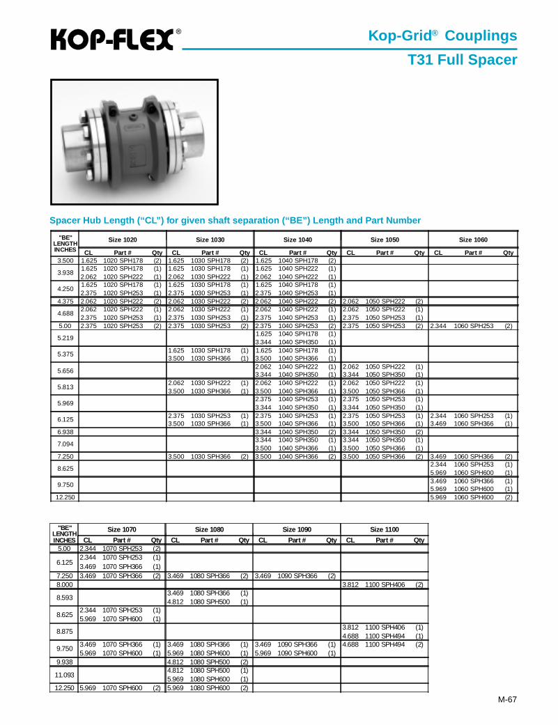
®
M-67
Spacer Hub Length (“CL”) for given shaft separation (“BE”) Length and Part Number
Kop-Grid ® Couplings
T31 Full Spacer
"BE"LENGTHINCHES
Size 1020 Size 1030 Size 1040 Size 1050 Size 1060
CL Part # Qty CL Part # Qty CL Part # Qty CL Part # Qty CL Part # Qty3.500 1.625 1020 SPH178 (2) 1.625 1030 SPH178 (2) 1.625 1040 SPH178 (2)
3.9381.625 1020 SPH178 (1) 1.625 1030 SPH178 (1) 1.625 1040 SPH222 (1)2.062 1020 SPH222 (1) 2.062 1030 SPH222 (1) 2.062 1040 SPH222 (1)
4.2501.625 1020 SPH178 (1) 1.625 1030 SPH178 (1) 1.625 1040 SPH178 (1)2.375 1020 SPH253 (1) 2.375 1030 SPH253 (1) 2.375 1040 SPH253 (1)
4.375 2.062 1020 SPH222 (2) 2.062 1030 SPH222 (2) 2.062 1040 SPH222 (2) 2.062 1050 SPH222 (2)
4.6882.062 1020 SPH222 (1) 2.062 1030 SPH222 (1) 2.062 1040 SPH222 (1) 2.062 1050 SPH222 (1)2.375 1020 SPH253 (1) 2.375 1030 SPH253 (1) 2.375 1040 SPH253 (1) 2.375 1050 SPH253 (1)
5.00 2.375 1020 SPH253 (2) 2.375 1030 SPH253 (2) 2.375 1040 SPH253 (2) 2.375 1050 SPH253 (2) 2.344 1060 SPH253 (2)
5.2191.625 1040 SPH178 (1)3.344 1040 SPH350 (1)
5.375 1.625 1030 SPH178 (1) 1.625 1040 SPH178 (1)3.500 1030 SPH366 (1) 3.500 1040 SPH366 (1)
5.6562.062 1040 SPH222 (1) 2.062 1050 SPH222 (1)3.344 1040 SPH350 (1) 3.344 1050 SPH350 (1)
5.8132.062 1030 SPH222 (1) 2.062 1040 SPH222 (1) 2.062 1050 SPH222 (1)3.500 1030 SPH366 (1) 3.500 1040 SPH366 (1) 3.500 1050 SPH366 (1)
5.9692.375 1040 SPH253 (1) 2.375 1050 SPH253 (1)3.344 1040 SPH350 (1) 3.344 1050 SPH350 (1)
6.125 2.375 1030 SPH253 (1) 2.375 1040 SPH253 (1) 2.375 1050 SPH253 (1) 2.344 1060 SPH253 (1)3.500 1030 SPH366 (1) 3.500 1040 SPH366 (1) 3.500 1050 SPH366 (1) 3.469 1060 SPH366 (1)
6.938 3.344 1040 SPH350 (2) 3.344 1050 SPH350 (2)
7.0943.344 1040 SPH350 (1) 3.344 1050 SPH350 (1)3.500 1040 SPH366 (1) 3.500 1050 SPH366 (1)
7.250 3.500 1030 SPH366 (2) 3.500 1040 SPH366 (2) 3.500 1050 SPH366 (2) 3.469 1060 SPH366 (2)
8.6252.344 1060 SPH253 (1)5.969 1060 SPH600 (1)
9.750 3.469 1060 SPH366 (1)5.969 1060 SPH600 (1)
12.250 5.969 1060 SPH600 (2)
"BE"LENGTHINCHES
Size 1070 Size 1080 Size 1090 Size 1100
CL Part # Qty CL Part # Qty CL Part # Qty CL Part # Qty5.00 2.344 1070 SPH253 (2)
6.1252.344 1070 SPH253 (1)3.469 1070 SPH366 (1)
7.250 3.469 1070 SPH366 (2) 3.469 1080 SPH366 (2) 3.469 1090 SPH366 (2)8.000 3.812 1100 SPH406 (2)
8.5933.469 1080 SPH366 (1)4.812 1080 SPH500 (1)
8.6252.344 1070 SPH253 (1)5.969 1070 SPH600 (1)
8.8753.812 1100 SPH406 (1)4.688 1100 SPH494 (1)
9.7503.469 1070 SPH366 (1) 3.469 1080 SPH366 (1) 3.469 1090 SPH366 (1) 4.688 1100 SPH494 (2)5.969 1070 SPH600 (1) 5.969 1080 SPH600 (1) 5.969 1090 SPH600 (1)
9.938 4.812 1080 SPH500 (2)
11.0934.812 1080 SPH500 (1)5.969 1080 SPH600 (1)
12.250 5.969 1070 SPH600 (2) 5.969 1080 SPH600 (2)
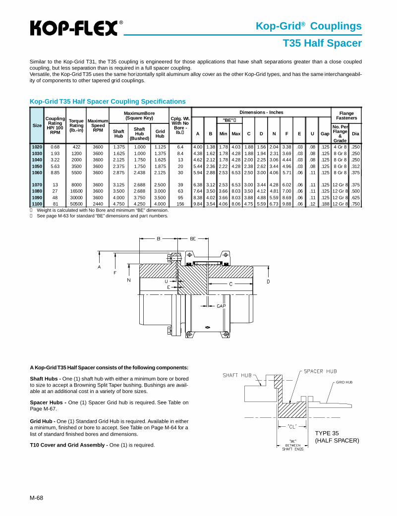
®
M-68
① Weight is calculated with No Bore and minimum “BE” dimension.② See page M-63 for standard “BE” dimensions and part numbers.
Kop-Grid T35 Half Spacer Coupling Specifications
Similar to the Kop-Grid T31, the T35 coupling is engineered for those applications that have shaft separations greater than a close coupledcoupling, but less separation than is required in a full spacer coupling.Versatile, the Kop-Grid T35 uses the same horizontally split aluminum alloy cover as the other Kop-Grid types, and has the same interchangeabil-ity of components to other tapered grid couplings.
A Kop-Grid T35 Half Spacer consists of the following components:
Shaft Hubs - One (1) shaft hub with either a minimum bore or boredto size to accept a Browning Split Taper bushing. Bushings are avail-able at an additional cost in a variety of bore sizes.
Spacer Hubs - One (1) Spacer Grid hub is required. See Table onPage M-67.
Grid Hub - One (1) Standard Grid Hub is required. Available in eithera minimum, finished or bore to accept. See Table on Page M-64 for alist of standard finished bores and dimensions.
T10 Cover and Grid Assembly - One (1) is required.
Kop-Grid ® Couplings
T35 Half Spacer
Size
CouplingRating
HP/ 100RPM
TorqueRating(lb.-in)
MaximumSpeedRPM
MaximumBore(Square Key) Cplg. Wt.
With NoBore -lb.①
Dimensions - Inches FlangeFasteners"BE" ②
ShaftHub
ShaftHub
(Bushed)
GridHub A B Min Max C D N F E U Gap
No. PerFlange
&Grade
Dia
1020 0.68 422 3600 1.375 1.000 1.125 6.4 4.00 1.38 1.78 4.03 1.88 1.56 2.04 3.38 .03 .08 .125 4 Gr 8 .2501030 1.93 1200 3600 1.625 1.000 1.375 8.4 4.38 1.62 1.78 4.28 1.88 1.94 2.31 3.69 .03 .08 .125 8 Gr 8 .2501040 3.22 2000 3600 2.125 1.750 1.625 13 4.62 2.12 1.78 4.28 2.00 2.25 3.06 4.44 .03 .08 .125 8 Gr 8 .2501050 5.63 3500 3600 2.375 1.750 1.875 20 5.44 2.36 2.22 4.28 2.38 2.62 3.44 4.96 .03 .08 .125 8 Gr 8 .3121060 8.85 5500 3600 2.875 2.438 2.125 30 5.94 2.88 2.53 6.53 2.50 3.00 4.06 5.71 .06 .11 .125 8 Gr 8 .375
1070 13 8000 3600 3.125 2.688 2.500 39 6.38 3.12 2.53 6.53 3.00 3.44 4.28 6.02 .06 .11 .125 12 Gr 8 .3751080 27 16500 3600 3.500 2.688 3.000 63 7.64 3.50 3.66 8.03 3.50 4.12 4.81 7.00 .06 .11 .125 12 Gr 8 .5001090 48 30000 3600 4.000 3.750 3.500 95 8.38 4.02 3.66 8.03 3.88 4.88 5.59 8.69 .06 .11 .125 12 Gr 8 .6251100 81 50500 2440 4.750 4.250 4.000 156 9.84 3.54 4.06 8.06 4.75 5.59 6.73 9.88 .06 .12 .188 12 Gr 8 .750
TYPE 35(HALF SPACER)
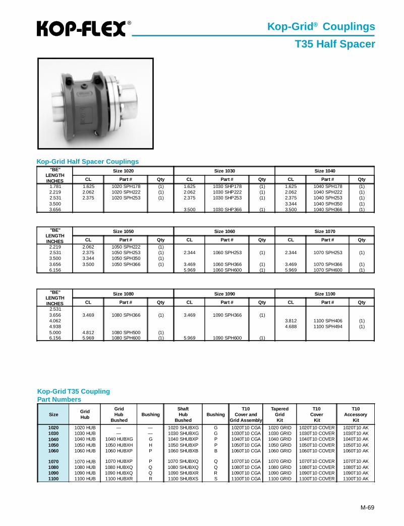
®
M-69
Kop-Grid T35 CouplingPart Numbers
Kop-Grid Half Spacer Couplings
"BE"LENGTHINCHES
Size 1080 Size 1090 Size 1100
CL Part # Qty CL Part # Qty CL Part # Qty2.5313.656 3.469 1080 SPH366 (1) 3.469 1090 SPH366 (1)4.062 3.812 1100 SPH406 (1)4.938 4.688 1100 SPH494 (1)5.000 4.812 1080 SPH500 (1)6.156 5.969 1080 SPH600 (1) 5.969 1090 SPH600 (1)
"BE"LENGTHINCHES
Size 1020 Size 1030 Size 1040
CL Part # Qty CL Part # Qty CL Part # Qty
1.781 1.625 1020 SPH178 (1) 1.625 1030 SHP178 (1) 1.625 1040 SPH178 (1)2.219 2.062 1020 SPH222 (1) 2.062 1030 SHP222 (1) 2.062 1040 SPH222 (1)2.531 2.375 1020 SPH253 (1) 2.375 1030 SHP253 (1) 2.375 1040 SPH253 (1)3.500 3.344 1040 SPH350 (1)3.656 3.500 1030 SHP366 (1) 3.500 1040 SPH366 (1)
"BE"LENGTHINCHES
Size 1050 Size 1060 Size 1070
CL Part # Qty CL Part # Qty CL Part # Qty
2.219 2.062 1050 SPH222 (1)2.531 2.375 1050 SPH253 (1) 2.344 1060 SPH253 (1) 2.344 1070 SPH253 (1)3.500 3.344 1050 SPH350 (1)3.656 3.500 1050 SPH366 (1) 3.469 1060 SPH366 (1) 3.469 1070 SPH366 (1)6.156 5.969 1060 SPH600 (1) 5.969 1070 SPH600 (1)
Kop-Grid ® Couplings
T35 Half Spacer
SizeGridHub
GridHub
BushedBushing
ShaftHub
BushedBushing
T10Cover and
Grid Assembly
TaperedGridKit
T10Cover
Kit
T10Accessory
Kit
1020 1020 HUB — — 1020 SHUBXG G 1020T10 CGA 1020 GRID 1020T10 COVER 1020T10 AK1030 1030 HUB — — 1030 SHUBXG G 1030T10 CGA 1030 GRID 1030T10 COVER 1030T10 AK1040 1040 HUB 1040 HUBXG G 1040 SHUBXP P 1040T10 CGA 1040 GRID 1040T10 COVER 1040T10 AK1050 1050 HUB 1050 HUBXH H 1050 SHUBXP P 1050T10 CGA 1050 GRID 1050T10 COVER 1050T10 AK1060 1060 HUB 1060 HUBXP P 1060 SHUBXB B 1060T10 CGA 1060 GRID 1060T10 COVER 1060T10 AK
1070 1070 HUB 1070 HUBXP P 1070 SHUBXQ Q 1070T10 CGA 1070 GRID 1070T10 COVER 1070T10 AK1080 1080 HUB 1080 HUBXQ Q 1080 SHUBXQ Q 1080T10 CGA 1080 GRID 1080T10 COVER 1080T10 AK1090 1090 HUB 1090 HUBXQ Q 1090 SHUBXR R 1090T10 CGA 1090 GRID 1090T10 COVER 1090T10 AK1100 1100 HUB 1100 HUBXR R 1100 SHUBXS S 1100T10 CGA 1100 GRID 1100T10 COVER 1100T10 AK

M-70
®
RM Series
These couplings are engineered to accommodate a broad range of demanding operatingconditions: boiler feed pumps, centrifugal and axial compressors, generator sets, test stands,gas and steam turbines, marine drives, etc.
The Kop-Flex HP disc coupling is the preferred choice for demanding turbo machinery applications. Superiorquality and a wide variety of standard and custom designs backed by unsurpassed engineering expertisecombined to make Kop-Flex the industry leader.
• Inherent fail-safe designs• Koplon coated flexible disc elements for maximum life• Factory assembled• Greatest reduced moment available• Dynamically balanced
KOP-FLEX High Performance Flexible Diaphragm Couplings (For more Information, see Bulletin 1300)
The patented Flexible Diaphragm Coupling from KOP-FLEX transmits torque from the drivingshaft via a rigid hub, then through a flexible diaphragm to a spacer. The diaphragm deformswhile transmitting this torque to accommodate misalignment. The spacer in turn drives matchingcomponents attached to the driven equipment. Outstanding design features are:
• Field Replaceable Stockable Diaphragms• Specially-Contoured One-Piece Diaphragm
Design• Patented Diaphragm Shape• Piloted Fits• Diaphragms are 15.5 PH Shot-Peened
Stainless Steel• Inherently Low Windage Design• Conforms To API 671 Specifications
HIGH PERFORMANCE DISC COUPLINGS...Available In Four Standard Styles...Designed And Manufactured To Meet API 671 As A Standard (For more Information, see Bulletin HP103)
MS Series RZ Series MP Series
KOP-FLEX® Reduced MomentHigh Performance Disc Coupling
Size #5.5 MDM-Jdiaphragm coupling
KOP-FLEX High Performance Gear Couplings (For more Information, Contact KOP-FLEX)
• Thousands in Service• Choose From Straight or Crowned Nitrided Gear Teeth,
Depending on your Application• Precision Lapped Teeth, if Required• Heat Treated Alloy Components
Size #6 Gear CouplingG.E. MS5001 Gas Turbine Driven
Compressor Train.
HIGH PERFORMANCE COUPLINGS
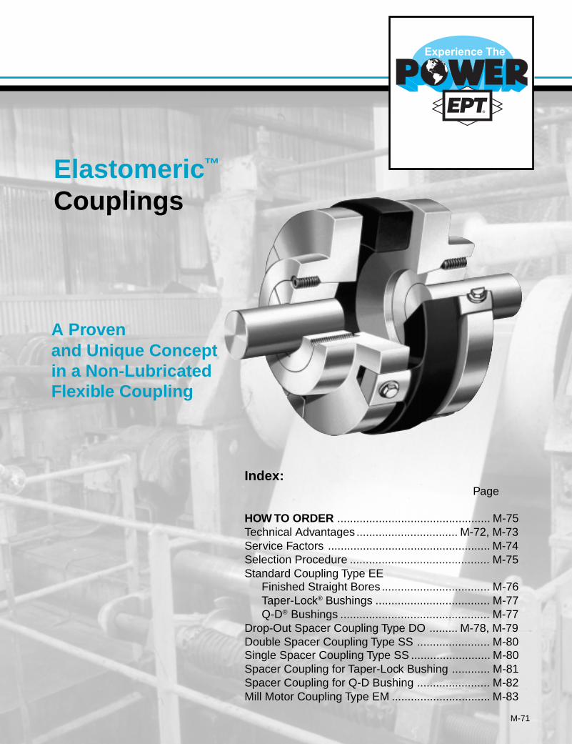
M-71
Elastomeric ™
Couplings
A Provenand Unique Conceptin a Non-LubricatedFlexible Coupling
Index:Page
HOW TO ORDER ................................................ M-75Technical Advantages ................................ M-72, M-73Service Factors ................................................... M-74Selection Procedure ............................................ M-75Standard Coupling Type EE
Finished Straight Bores .................................. M-76Taper-Lock® Bushings .................................... M-77Q-D® Bushings ............................................... M-77
Drop-Out Spacer Coupling Type DO ......... M-78, M-79Double Spacer Coupling Type SS ....................... M-80Single Spacer Coupling Type SS ......................... M-80Spacer Coupling for Taper-Lock Bushing ............ M-81Spacer Coupling for Q-D Bushing ....................... M-82Mill Motor Coupling Type EM ............................... M-83
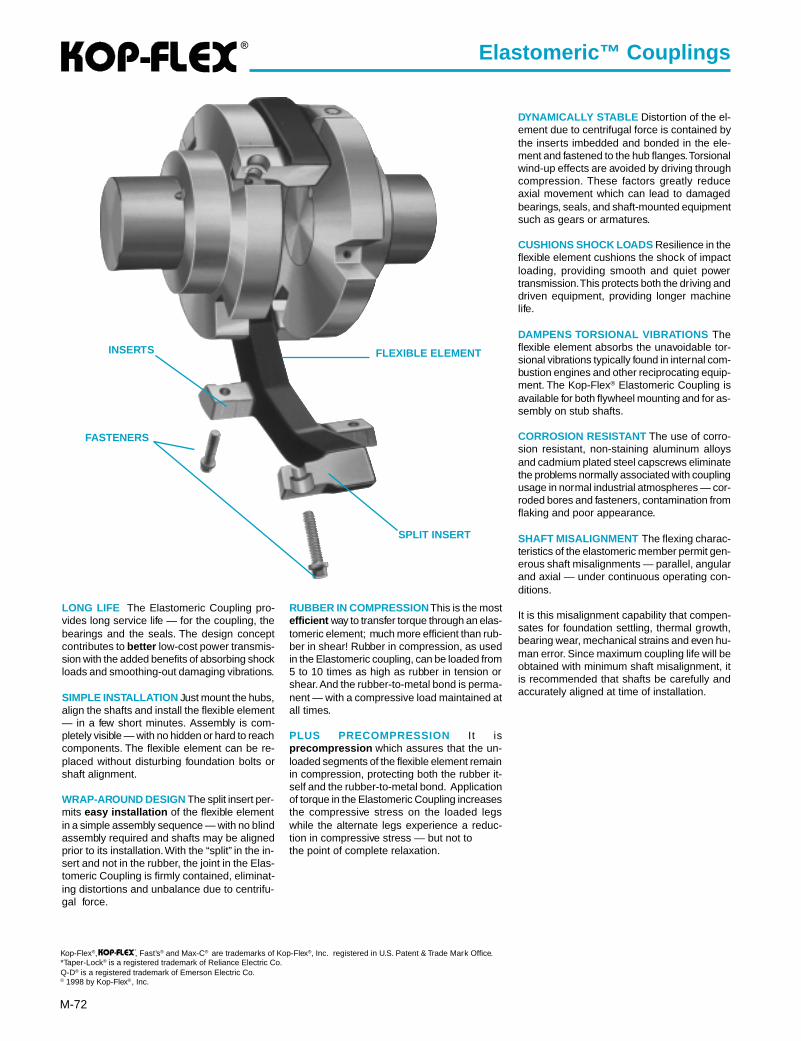
®
M-72
LONG LIFE The Elastomeric Coupling pro-vides long service life — for the coupling, thebearings and the seals. The design conceptcontributes to better low-cost power transmis-sion with the added benefits of absorbing shockloads and smoothing-out damaging vibrations.
SIMPLE INSTALLATION Just mount the hubs,align the shafts and install the flexible element— in a few short minutes. Assembly is com-pletely visible — with no hidden or hard to reachcomponents. The flexible element can be re-placed without disturbing foundation bolts orshaft alignment.
WRAP-AROUND DESIGN The split insert per-mits easy installation of the flexible elementin a simple assembly sequence — with no blindassembly required and shafts may be alignedprior to its installation. With the “split” in the in-sert and not in the rubber, the joint in the Elas-tomeric Coupling is firmly contained, eliminat-ing distortions and unbalance due to centrifu-gal force.
Kop-Flex®, , Fast’s® and Max-C® are trademarks of Kop-Flex®, Inc. registered in U.S. Patent & Trade Mark Office.*Taper-Lock® is a registered trademark of Reliance Electric Co.Q-D® is a registered trademark of Emerson Electric Co.© 1998 by Kop-Flex®, Inc.
®
Elastomeric™ Couplings
RUBBER IN COMPRESSION This is the mostefficient way to transfer torque through an elas-tomeric element; much more efficient than rub-ber in shear! Rubber in compression, as usedin the Elastomeric coupling, can be loaded from5 to 10 times as high as rubber in tension orshear. And the rubber-to-metal bond is perma-nent — with a compressive load maintained atall times.
PLUS PRECOMPRESSION It isprecompression which assures that the un-loaded segments of the flexible element remainin compression, protecting both the rubber it-self and the rubber-to-metal bond. Applicationof torque in the Elastomeric Coupling increasesthe compressive stress on the loaded legswhile the alternate legs experience a reduc-tion in compressive stress — but not tothe point of complete relaxation.
DYNAMICALLY STABLE Distortion of the el-ement due to centrifugal force is contained bythe inserts imbedded and bonded in the ele-ment and fastened to the hub flanges. Torsionalwind-up effects are avoided by driving throughcompression. These factors greatly reduceaxial movement which can lead to damagedbearings, seals, and shaft-mounted equipmentsuch as gears or armatures.
CUSHIONS SHOCK LOADS Resilience in theflexible element cushions the shock of impactloading, providing smooth and quiet powertransmission. This protects both the driving anddriven equipment, providing longer machinelife.
DAMPENS TORSIONAL VIBRATIONS Theflexible element absorbs the unavoidable tor-sional vibrations typically found in internal com-bustion engines and other reciprocating equip-ment. The Kop-Flex® Elastomeric Coupling isavailable for both flywheel mounting and for as-sembly on stub shafts.
CORROSION RESISTANT The use of corro-sion resistant, non-staining aluminum alloysand cadmium plated steel capscrews eliminatethe problems normally associated with couplingusage in normal industrial atmospheres — cor-roded bores and fasteners, contamination fromflaking and poor appearance.
SHAFT MISALIGNMENT The flexing charac-teristics of the elastomeric member permit gen-erous shaft misalignments — parallel, angularand axial — under continuous operating con-ditions.
It is this misalignment capability that compen-sates for foundation settling, thermal growth,bearing wear, mechanical strains and even hu-man error. Since maximum coupling life will beobtained with minimum shaft misalignment, itis recommended that shafts be carefully andaccurately aligned at time of installation.
INSERTS
FASTENERS
SPLIT INSERT
FLEXIBLE ELEMENT
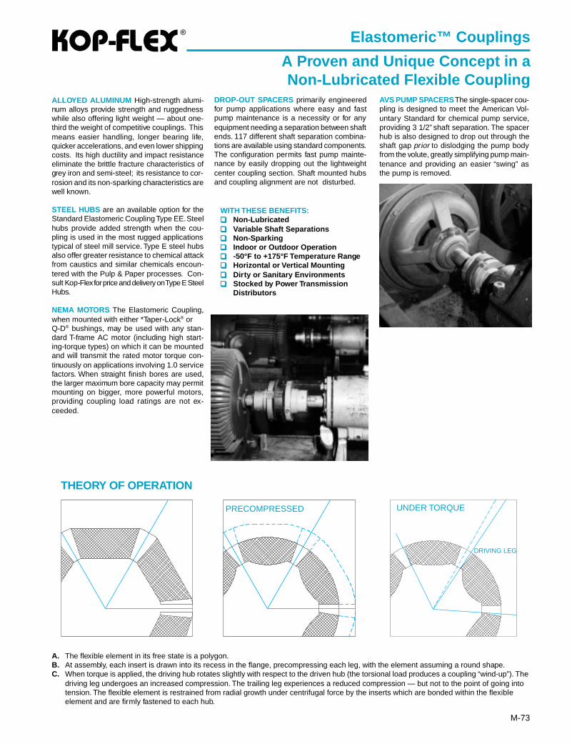
®
M-73
Elastomeric™ Couplings
A Proven and Unique Concept in aNon-Lubricated Flexible Coupling
THEORY OF OPERATION
A. The flexible element in its free state is a polygon.B. At assembly, each insert is drawn into its recess in the flange, precompressing each leg, with the element assuming a round shape.C. When torque is applied, the driving hub rotates slightly with respect to the driven hub (the torsional load produces a coupling “wind-up”). The
driving leg undergoes an increased compression. The trailing leg experiences a reduced compression — but not to the point of going intotension. The flexible element is restrained from radial growth under centrifugal force by the inserts which are bonded within the flexibleelement and are firmly fastened to each hub.
PRECOMPRESSED
DRIVING LEG
ALLOYED ALUMINUM High-strength alumi-num alloys provide strength and ruggednesswhile also offering light weight — about one-third the weight of competitive couplings. Thismeans easier handling, longer bearing life,quicker accelerations, and even lower shippingcosts. Its high ductility and impact resistanceeliminate the brittle fracture characteristics ofgrey iron and semi-steel; its resistance to cor-rosion and its non-sparking characteristics arewell known.
STEEL HUBS are an available option for theStandard Elastomeric Coupling Type EE. Steelhubs provide added strength when the cou-pling is used in the most rugged applicationstypical of steel mill service. Type E steel hubsalso offer greater resistance to chemical attackfrom caustics and similar chemicals encoun-tered with the Pulp & Paper processes. Con-sult Kop-Flex for price and delivery on Type E SteelHubs.
NEMA MOTORS The Elastomeric Coupling,when mounted with either *Taper-Lock® orQ-D® bushings, may be used with any stan-dard T-frame AC motor (including high start-ing-torque types) on which it can be mountedand will transmit the rated motor torque con-tinuously on applications involving 1.0 servicefactors. When straight finish bores are used,the larger maximum bore capacity may permitmounting on bigger, more powerful motors,providing coupling load ratings are not ex-ceeded.
DROP-OUT SPACERS primarily engineeredfor pump applications where easy and fastpump maintenance is a necessity or for anyequipment needing a separation between shaftends. 117 different shaft separation combina-tions are available using standard components.The configuration permits fast pump mainte-nance by easily dropping out the lightweightcenter coupling section. Shaft mounted hubsand coupling alignment are not disturbed.
AVS PUMP SPACERS The single-spacer cou-pling is designed to meet the American Vol-untary Standard for chemical pump service,providing 3 1/2” shaft separation. The spacerhub is also designed to drop out through theshaft gap prior to dislodging the pump bodyfrom the volute, greatly simplifying pump main-tenance and providing an easier “swing” asthe pump is removed.
UNDER TORQUE
WITH THESE BENEFITS:❑❑❑❑❑ Non-Lubricated❑❑❑❑❑ Variable Shaft Separations❑❑❑❑❑ Non-Sparking❑❑❑❑❑ Indoor or Outdoor Operation❑❑❑❑❑ -50°F to +175°F Temperature Range❑❑❑❑❑ Horizontal or Vertical Mounting❑❑❑❑❑ Dirty or Sanitary Environments❑❑❑❑❑ Stocked by Power Transmission
Distributors
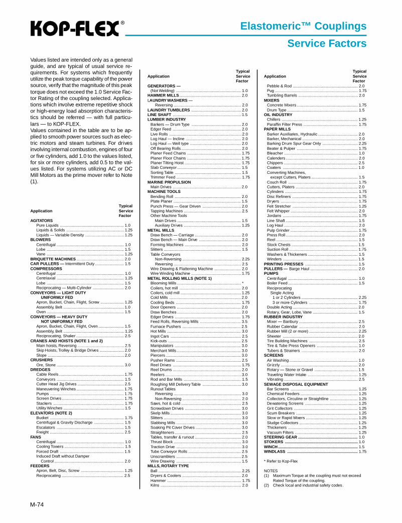
®
M-74
TypicalApplication Ser vice
FactorAGITATORS
Pure Liquids .......................................................... 1.0Liquids & Solids .................................................... 1.25Liquids — Variable Density ................................... 1.25
BLOWERSCentrifugal ............................................................. 1.0Lobe ...................................................................... 1.5Vane ...................................................................... 1.25
BRIQUETTE MACHINES ........................................... 2.0CAR PULLERS — Intermittent Duty .......................... 1.5COMPRESSORS
Centrifugal ............................................................. 1.0Centriaxial ............................................................. 1.25Lobe ...................................................................... 1.5Reciprocating — Multi-Cylinder ............................ 2.0
CONVEYORS — LIGHT DUTY UNIFORMLY FEDApron, Bucket, Chain, Flight, Screw ..................... 1.25Assembly, Belt ....................................................... 1.0Oven ...................................................................... 1.5
CONVEYORS — HEAVY DUTY NOT UNIFORMLY FEDApron, Bucket, Chain, Flight, Oven ....................... 1.5Assembly, Belt ....................................................... 1.25Reciprocating, Shaker ........................................... 2.5
CRANES AND HOISTS (NOTE 1 and 2)Main hoists, Reversing .......................................... 2.5Skip Hoists, Trolley & Bridge Drives ...................... 2.0Slope ..................................................................... 2.0
CRUSHERSOre, Stone ............................................................. 3.0
DREDGESCable Reels ........................................................... 1.75Conveyors ............................................................. 1.5Cutter Head Jig Drives .......................................... 2.5Maneuvering Winches ........................................... 1.75Pumps ................................................................... 1.75Screen Drives ........................................................ 1.75Stackers ................................................................ 1.75Utility Winches ....................................................... 1.5
ELEVATORS (NOTE 2)Bucket ................................................................... 1.75Centrifugal & Gravity Discharge ........................... 1.5Escalators ............................................................. 1.5Freight ................................................................... 2.5
FANSCentrifugal ............................................................. 1.0Cooling Towers ...................................................... 1.5Forced Draft .......................................................... 1.5Induced Draft without Damper Control ............................................................... 2.0
FEEDERSApron, Belt, Disc, Screw ....................................... 1.25Reciprocating ........................................................ 2.5
TypicalApplication Ser vice
FactorGENERATORS —
(Not Welding) ........................................................... 1.0HAMMER MILLS ........................................................ 2.0LAUNDRY WASHERS —
Reversing ............................................................. 2.0LAUNDRY TUMBLERS ............................................. 2.0LINE SHAFT .............................................................. 1.5LUMBER INDUSTRY
Barkers — Drum Type ............................................. 2.0Edger Feed .............................................................. 2.0Live Rolls ................................................................. 2.0Log Haul — Incline .................................................. 2.0Log Haul — Well type .............................................. 2.0Off Bearing Rolls ...................................................... 2.0Planer Feed Chains ................................................. 1.75Planer Floor Chains ................................................. 1.75Planer Tilting Hoist ................................................... 1.75Slab Conveyor .......................................................... 1.5Sorting Table ............................................................ 1.5Trimmer Feed ........................................................... 1.75
MARINE PROPULSIONMain Drives .............................................................. 2.0
MACHINE TOOLSBending Roll ............................................................ 2.0Plate Planer ............................................................. 1.5Punch Press — Gear Driven ................................... 2.0Tapping Machines .................................................... 2.5Other Machine Tools Main Drives .......................................................... 1.5 Auxiliary Drives .................................................... 1.25
METAL MILLSDraw Bench — Carriage .......................................... 2.0Draw Bench — Main Drive ...................................... 2.0Forming Machines ................................................... 2.0Slitters ...................................................................... 1.5Table Conveyors Non-Reversing ..................................................... 2.25 Reversing ............................................................. 2.5Wire Drawing & Flattening Machine ........................ 2.0Wire Winding Machine ............................................. 1.75
METAL ROLLING MILLS (NOTE 1)Blooming Mills .......................................................... *Coilers, hot mill ........................................................ 2.0Coilers, cold mill ....................................................... 1.25Cold Mills ................................................................. 2.0Cooling Beds ........................................................... 1.75Door Openers .......................................................... 2.0Draw Benches .......................................................... 2.0Edger Drives ............................................................ 1.75Feed Rolls, Reversing Mills ..................................... 3.5Furnace Pushers ..................................................... 2.5Hot Mills ................................................................... 3.0Ingot Cars ................................................................ 2.5Kick-outs .................................................................. 2.5Manipulators ............................................................ 3.0Merchant Mills .......................................................... 3.0Piercers .................................................................... 3.0Pusher Rams ........................................................... 2.5Reel Drives .............................................................. 1.75Reel Drums .............................................................. 2.0Reelers ..................................................................... 3.0Rod and Bar Mills .................................................... 1.5Roughing Mill Delivery Table ................................... 3.0Runout Tables Reversing ............................................................. 3.0 Non-Reversing ..................................................... 2.0Saws, hot & cold ...................................................... 2.5Screwdown Drives ................................................... 3.0Skelp Mills ................................................................ 3.0Slitters ...................................................................... 3.0Slabbing Mills ........................................................... 3.0Soaking Pit Cover Drives ......................................... 3.0Straighteners ............................................................ 2.5Tables, transfer & runout .......................................... 2.0Thrust Block ............................................................. 3.0Traction Drive ........................................................... 3.0Tube Conveyor Rolls ................................................ 2.5Unscramblers ........................................................... 2.5Wire Drawing ........................................................... 1.5
MILLS, ROTARY TYPEBall ........................................................................... 2.25Dryers & Coolers ..................................................... 2.0Hammer ................................................................... 1.75Kilns ......................................................................... 2.0
TypicalApplication Ser vice
FactorPebble & Rod ........................................................... 2.0Pug ........................................................................... 1.75Tumbling Barrels ...................................................... 2.0
MIXERSConcrete Mixers ....................................................... 1.75Drum Type ................................................................ 1.5
OIL INDUSTRYChillers ..................................................................... 1.25Paraffin Filter Press ................................................. 1.75
PAPER MILLSBarker Auxiliaries, Hydraulic .................................... 2.0Barker, Mechanical .................................................. 2.0Barking Drum Spur Gear Only ................................ 2.25Beater & Pulper ....................................................... 1.75Bleacher ................................................................... 1.0Calenders ................................................................. 2.0Chippers ................................................................... 2.5Coaters .................................................................... 1.0Converting Machines, except Cutters, Platers .......................................... 1.5Couch Roll ............................................................... 1.75Cutters, Platers ........................................................ 2.0Cylinders .................................................................. 1.75Disc Refiners ........................................................... 1.75Dryers ...................................................................... 1.75Felt Stretcher ........................................................... 1.25Felt Whipper ............................................................. 2.0Jordans .................................................................... 1.75Line Shaft ................................................................. 1.5Log Haul ................................................................... 2.0Pulp Grinder ............................................................. 1.75Press Roll ................................................................. 2.0Reel .......................................................................... 1.5Stock Chests ............................................................ 1.5Suction Roll .............................................................. 1.75Washers & Thickeners ............................................. 1.5Winders .................................................................... 1.5
PRINTING PRESSES ................................................ 1.5PULLERS — Barge Haul ........................................... 2.0PUMPS
Centrifugal ............................................................... 1.0Boiler Feed ............................................................... 1.5Reciprocating Single Acting 1 or 2 Cylinders ................................................... 2.25 3 or more Cylinders ............................................ 1.75Double Acting ........................................................... 2.0Rotary, Gear, Lobe, Vane ......................................... 1.5
RUBBER INDUSTRYMixer — Banbury ..................................................... 2.5Rubber Calendar ..................................................... 2.0Rubber Mill (2 or more) ............................................ 2.25Sheeter .................................................................... 2.0Tire Building Machines ............................................ 2.5Tire & Tube Press Openers ..................................... 1.0Tubers & Strainers ................................................... 2.0
SCREENSAir Washing .............................................................. 1.0Grizzly ...................................................................... 2.0Rotary — Stone or Gravel ....................................... 1.5Traveling Water Intake ............................................. 1.25Vibrating ................................................................... 2.5
SEWAGE DISPOSAL EQUIPMENTBar Screens ............................................................. 1.25Chemical Feeders .................................................... 1.25Collectors, Circuline or Straightline ......................... 1.25Dewatering Screens ................................................ 1.25Grit Collectors .......................................................... 1.25Scum Breakers ........................................................ 1.25Slow or Rapid Mixers ............................................... 1.25Sludge Collectors ..................................................... 1.25Thickeners ............................................................... 1.25Vacuum Filters ......................................................... 1.25
STEERING GEAR ...................................................... 1.0STOKERS .................................................................. 1.0WINCH ........................................................................ 1.5WINDLASS ................................................................ 1.75
* Refer to Kop-Flex
NOTES(1) Maximum Torque at the coupling must not exceed
Rated Torque of the coupling.(2) Check local and industrial safety codes.
Elastomeric™ Couplings
Service FactorsValues listed are intended only as a generalguide, and are typical of usual service re-quirements. For systems which frequentlyutilize the peak torque capability of the powersource, verify that the magnitude of this peaktorque does not exceed the 1.0 Service Fac-tor Rating of the coupling selected. Applica-tions which involve extreme repetitive shockor high-energy load absorption characteris-tics should be referred — with full particu-lars — to KOP-FLEX.Values contained in the table are to be ap-plied to smooth power sources such as elec-tric motors and steam turbines. For drivesinvolving internal combustion, engines of fouror five cylinders, add 1.0 to the values listed,for six or more cylinders, add 0.5 to the val-ues listed. For systems utilizing AC or DCMill Motors as the prime mover refer to Note(1).
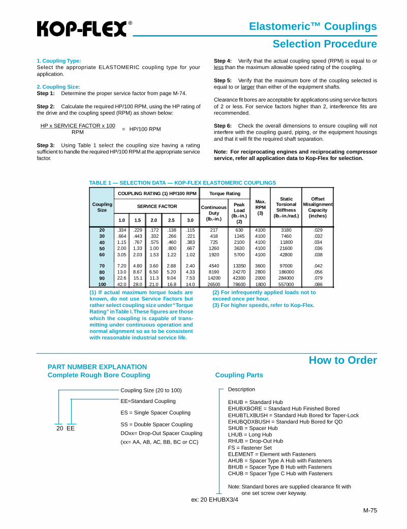
®
M-75
Elastomeric™ Couplings
Selection Procedure
TABLE 1 — SELECTION DATA — KOP-FLEX ELASTOMERIC COUPLINGS
(1) If actual maximum torque loads areknown, do not use Service Factors butrather select coupling size under “TorqueRating” in Table I. These figures are thosewhich the coupling is capable of trans-mitting under continuous operation andnormal alignment so as to be consistentwith reasonable industrial service life.
(2) For infrequently applied loads not toexceed once per hour.(3) For higher speeds, refer to Kop-Flex.
1. Coupling Type:Select the appropriate ELASTOMERIC coupling type for yourapplication.
2. Coupling Size:Step 1: Determine the proper service factor from page M-74.
Step 2: Calculate the required HP/100 RPM, using the HP rating ofthe drive and the coupling speed (RPM) as shown below:
HP x SERVICE FACTOR x 100= HP/100 RPMRPM
Step 3: Using Table 1 select the coupling size having a ratingsufficient to handle the required HP/100 RPM at the appropriate servicefactor.
Step 4: Verify that the actual coupling speed (RPM) is equal to orless than the maximum allowable speed rating of the coupling.
Step 5: Verify that the maximum bore of the coupling selected isequal to or larger than either of the equipment shafts.
Clearance fit bores are acceptable for applications using service factorsof 2 or less. For service factors higher than 2, interference fits arerecommended.
Step 6: Check the overall dimensions to ensure coupling will notinterfere with the coupling guard, piping, or the equipment housingsand that it will fit the required shaft separation.
Note: For reciprocating engines and reciprocating compressorservice, refer all application data to Kop-Flex for selection.
Description
EHUB = Standard HubEHUBXBORE = Standard Hub Finished BoredEHUBTLXBUSH = Standard Hub Bored for Taper-LockEHUBQDXBUSH = Standard Hub Bored for QDSHUB = Spacer HubLHUB = Long HubRHUB = Drop-Out HubFS = Fastener SetELEMENT = Element with FastenersAHUB = Spacer Type A Hub with FastenersBHUB = Spacer Type B Hub with FastenersCHUB = Spacer Type C Hub with Fasteners
Note: Standard bores are supplied clearance fit withone set screw over keyway.
PART NUMBER EXPLANATIONComplete Rough Bore Coupling
Coupling Size (20 to 100)
EE=Standard Coupling
ES = Single Spacer Coupling
SS = Double Spacer Coupling
DOxx= Drop-Out Spacer Coupling
(xx= AA, AB, AC, BB, BC or CC)
Coupling Parts
20 EE
ex: 20 EHUBX3/4
How to Order
CouplingSize
COUPLING RATING (1) HP/100 RPM Torque Rating
Max.RPM(3)
StaticTorsionalStiffness
(lb.-in./rad.)
OffsetMisalignment
Capacity(inches)
SERVICE FACTOR ContinuousDuty
(lb.-in.)
PeakLoad
(lb.-in.)(2)1.0 1.5 2.0 2.5 3.0
20 .334 .229 .172 .138 .115 217 630 4100 3180 .02930 .664 .443 .332 .266 .221 418 1245 4100 7460 .03240 1.15 .767 .575 .460 .383 725 2100 4100 11800 .03450 2.00 1.33 1.00 .800 .667 1260 3630 4100 21600 .03660 3.05 2.03 1.53 1.22 1.02 1920 5700 4100 42800 .038
70 7.20 4.80 3.60 2.88 2.40 4540 13350 3600 97000 .04280 13.0 8.67 6.50 5.20 4.33 8190 24270 2800 186000 .05690 22.6 15.1 11.3 9.04 7.53 14200 42300 2000 284000 .079100 42.0 28.0 21.0 16.8 14.0 26500 78600 1800 557000 .086
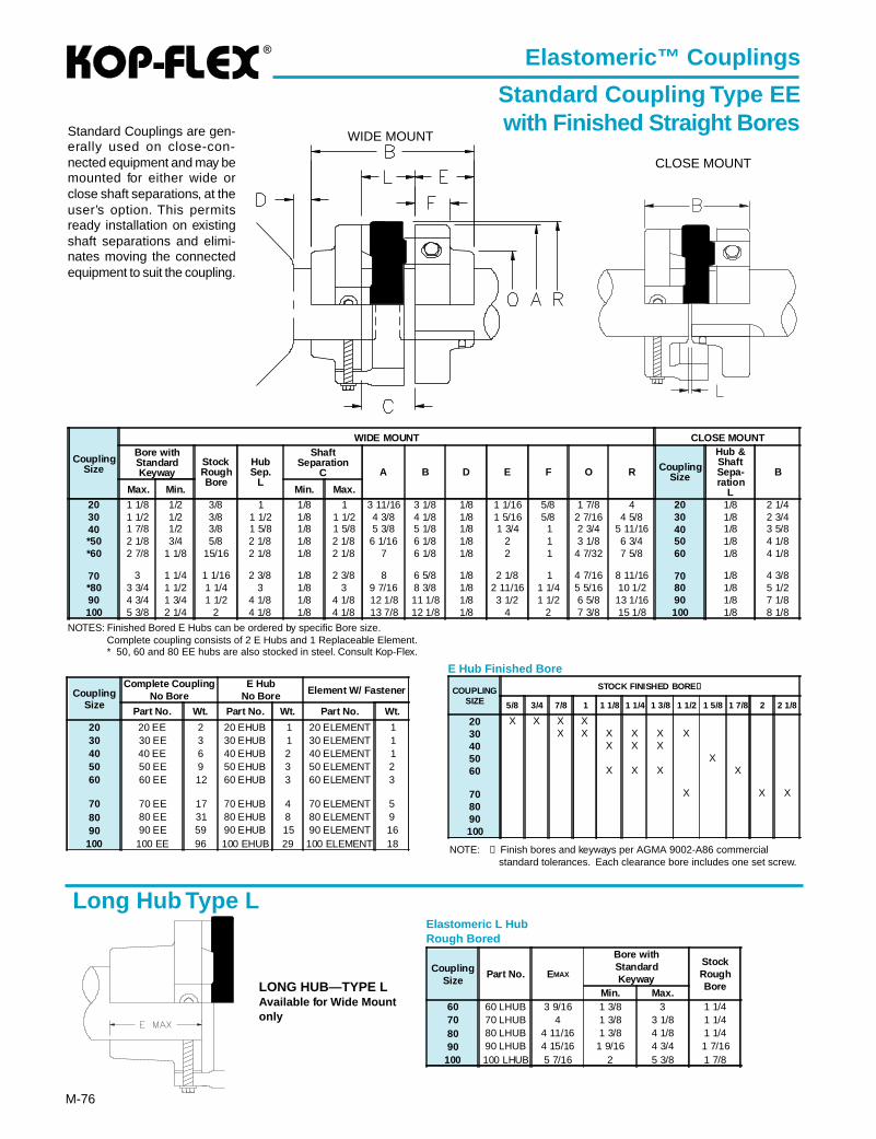
®
M-76
Elastomeric™ Couplings
Standard Coupling Type EEwith Finished Straight BoresStandard Couplings are gen-
erally used on close-con-nected equipment and may bemounted for either wide orclose shaft separations, at theuser’s option. This permitsready installation on existingshaft separations and elimi-nates moving the connectedequipment to suit the coupling.
WIDE MOUNT
CLOSE MOUNT
NOTES: Finished Bored E Hubs can be ordered by specific Bore size.Complete coupling consists of 2 E Hubs and 1 Replaceable Element.* 50, 60 and 80 EE hubs are also stocked in steel. Consult Kop-Flex.
Long Hub Type LElastomeric L HubRough Bored
LONG HUB—TYPE LAvailable for Wide Mountonly
CouplingSize
WIDE MOUNT CLOSE MOUNTBore withStandardKeyway
StockRoughBore
HubSep.
L
ShaftSeparation
C A B D E F O R CouplingSize
Hub &ShaftSepa-ration
L
B
Max. Min. Min. Max.
20 1 1/8 1/2 3/8 1 1/8 1 3 11/16 3 1/8 1/8 1 1/16 5/8 1 7/8 4 20 1/8 2 1/430 1 1/2 1/2 3/8 1 1/2 1/8 1 1/2 4 3/8 4 1/8 1/8 1 5/16 5/8 2 7/16 4 5/8 30 1/8 2 3/440 1 7/8 1/2 3/8 1 5/8 1/8 1 5/8 5 3/8 5 1/8 1/8 1 3/4 1 2 3/4 5 11/16 40 1/8 3 5/8*50 2 1/8 3/4 5/8 2 1/8 1/8 2 1/8 6 1/16 6 1/8 1/8 2 1 3 1/8 6 3/4 50 1/8 4 1/8*60 2 7/8 1 1/8 15/16 2 1/8 1/8 2 1/8 7 6 1/8 1/8 2 1 4 7/32 7 5/8 60 1/8 4 1/8
70 3 1 1/4 1 1/16 2 3/8 1/8 2 3/8 8 6 5/8 1/8 2 1/8 1 4 7/16 8 11/16 70 1/8 4 3/8*80 3 3/4 1 1/2 1 1/4 3 1/8 3 9 7/16 8 3/8 1/8 2 11/16 1 1/4 5 5/16 10 1/2 80 1/8 5 1/290 4 3/4 1 3/4 1 1/2 4 1/8 1/8 4 1/8 12 1/8 11 1/8 1/8 3 1/2 1 1/2 6 5/8 13 1/16 90 1/8 7 1/8100 5 3/8 2 1/4 2 4 1/8 1/8 4 1/8 13 7/8 12 1/8 1/8 4 2 7 3/8 15 1/8 100 1/8 8 1/8
CouplingSize
Part No. E MAX
Bore withStandardKeyway
StockRoughBore
Min. Max.60 60 LHUB 3 9/16 1 3/8 3 1 1/470 70 LHUB 4 1 3/8 3 1/8 1 1/480 80 LHUB 4 11/16 1 3/8 4 1/8 1 1/490 90 LHUB 4 15/16 1 9/16 4 3/4 1 7/16
100 100 LHUB 5 7/16 2 5 3/8 1 7/8
NOTE: ➀ Finish bores and keyways per AGMA 9002-A86 commercialstandard tolerances. Each clearance bore includes one set screw.
COUPLINGSIZE
STOCK FINISHED BORE➀
5/8 3/4 7/8 1 1 1/8 1 1/4 1 3/8 1 1/2 1 5/8 1 7/8 2 2 1/8
20 X X X X30 X X X X X X40 X X X50 X60 X X X X
70 X X X8090100
E Hub Finished Bore
CouplingSize
Complete CouplingNo Bore
E HubNo Bore Element W/ Fastener
Part No. Wt. Part No. Wt. Part No. Wt.
20 20 EE 2 20 EHUB 1 20 ELEMENT 130 30 EE 3 30 EHUB 1 30 ELEMENT 140 40 EE 6 40 EHUB 2 40 ELEMENT 150 50 EE 9 50 EHUB 3 50 ELEMENT 260 60 EE 12 60 EHUB 3 60 ELEMENT 3
70 70 EE 17 70 EHUB 4 70 ELEMENT 580 80 EE 31 80 EHUB 8 80 ELEMENT 990 90 EE 59 90 EHUB 15 90 ELEMENT 16
100 100 EE 96 100 EHUB 29 100 ELEMENT 18
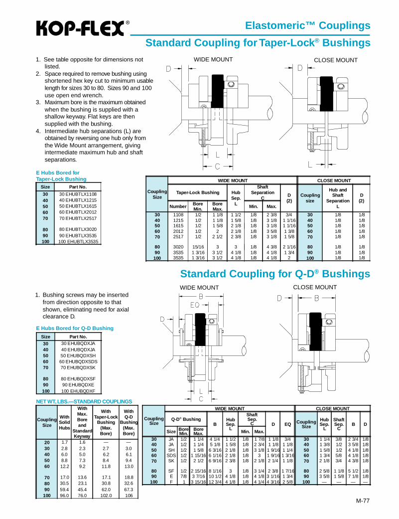
®
M-77
Elastomeric™ Couplings
Standard Coupling for Taper-Lock ® Bushings1. See table opposite for dimensions not
listed.2. Space required to remove bushing using
shortened hex key cut to minimum usablelength for sizes 30 to 80. Sizes 90 and 100use open end wrench.
3. Maximum bore is the maximum obtainedwhen the bushing is supplied with ashallow keyway. Flat keys are thensupplied with the bushing.
4. Intermediate hub separations (L) areobtained by reversing one hub only fromthe Wide Mount arrangement, givingintermediate maximum hub and shaftseparations.
Standard Coupling for Q-D ® Bushings
1. Bushing screws may be insertedfrom direction opposite to thatshown, eliminating need for axialclearance D.
E Hubs Bored for Q-D Bushing
E Hubs Bored forTaper-Lock Bushing
WIDE MOUNT CLOSE MOUNT
WIDE MOUNT CLOSE MOUNT
CouplingSize
WIDE MOUNT CLOSE MOUNT
Q-D® BushingB
HubSep.
L
ShaftSep.
C D EQ CouplingSize
HubSep.
L
ShaftSep.
CB D
Size BoreMin.
BoreMax. Min. Max.
30 JA 1/2 1 1/4 4 1/4 1 1/2 1/8 1 7/8 1 1/8 3/4 30 1 1/4 3/8 2 3/4 1/840 JA 1/2 1 1/4 5 1/8 1 5/8 1/8 2 3/4 1 1/8 1 1/8 40 1 3/8 1/2 3 5/8 1/850 SH 1/2 1 5/8 6 3/16 2 1/8 1/8 3 1/8 1 9/16 1 1/4 50 1 5/8 1/2 4 1/8 1/860 SDS 1/2 1 15/16 6 1/16 2 1/8 1/8 3 1 9/16 1 3/16 60 1 3/4 5/8 4 1/8 1/870 SK 1/2 2 1/2 6 9/16 2 3/8 1/8 2 1/8 2 1/4 1 1/8 70 2 1/8 3/4 4 3/8 1/8
80 SF 1/2 2 15/16 8 1/16 3 1/8 3 1/4 2 3/8 1 7/16 80 2 5/8 1 1/8 5 1/2 1/890 E 7/8 3 7/16 10 1/2 4 1/8 1/8 4 1/8 3 1/16 1 3/4 90 3 5/8 1 5/8 7 1/8 1/8
100 F 1 3 15/16 12 3/4 4 1/8 1/8 4 1/4 4 3/16 2 5/8 100 — — — —
NET WT, LBS.—STANDARD COUPLINGS
CouplingSize
WithSolidHubs
WithMax.Boreand
StandardKeyway
WithTaper-Lock
Bushing(Max.Bore)
WithQ-D
Bushing(Max.Bore)
20 1.7 1.6 — —30 2.8 2.3 2.7 3.040 6.0 5.0 6.2 6.150 8.8 7.3 8.4 9.460 12.2 9.2 11.8 13.0
70 17.0 13.6 17.1 18.880 30.5 23.1 30.8 32.690 59.4 45.4 62.0 67.3
100 96.0 76.0 102.0 106
Size Part No.
30 30 EHUBTLX110840 40 EHUBTLX121550 50 EHUBTLX161560 60 EHUBTLX201270 70 EHUBTLX2517
80 80 EHUBTLX302090 90 EHUBTLX3535100 100 EHUBTLX3535
CouplingSize
WIDE MOUNT CLOSE MOUNT
Taper-Lock Bushing HubSep.
L
ShaftSeparation
CD(2)
Couplingsize
Hub andShaft
SeparationL
D(2)
Number BoreMin.
BoreMax. Min. Max.
30 1108 1/2 1 1/8 1 1/2 1/8 2 3/8 3/4 30 1/8 1/840 1215 1/2 1 1/8 1 5/8 1/8 3 1/8 1 1/16 40 1/8 1/850 1615 1/2 1 5/8 2 1/8 1/8 3 1/8 1 1/16 50 1/8 1/860 2012 1/2 2 2 1/8 1/8 3 5/8 1 3/8 60 1/8 1/870 2517 1/2 2 1/2 2 3/8 1/8 3 1/8 1 5/8 70 1/8 1/8
80 3020 15/16 3 3 1/8 4 3/8 2 1/16 80 1/8 1/890 3535 1 3/16 3 1/2 4 1/8 1/8 4 1/8 1 3/4 90 1/8 1/8
100 3535 1 3/16 3 1/2 4 1/8 1/8 4 1/8 2 100 1/8 1/8
Size Part No.
30 30 EHUBQDXJA40 40 EHUBQDXJA50 50 EHUBQDXSH60 60 EHUBQDXSDS70 70 EHUBQDXSK
80 80 EHUBQDXSF90 90 EHUBQDXE100 100 EHUBQDXF
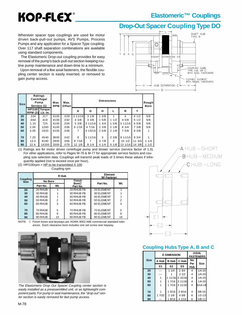
®
M-78
Elastomeric™ Couplings
Drop-Out Spacer Coupling T ype DOWherever spacer type couplings are used for motordriven back-pull-out pumps, AVS Pumps, ProcessPumps and any application for a Spacer Type coupling.Over 117 shaft separation combinations are availableusing standard components. The Elastomeric Drop-out coupling provides for easyremoval of the pump’s back-pull-out section keeping rou-tine pump maintenance and down-time to a minimum. Upon removal of a few axial fasteners, the flexible cou-pling center section is easily inserted, or removed togain pump access.
(1) Ratings are for motor driven centrifugal pump and blower service (service factor of 1.0).For other applications, refer to Pages M-76 & M-77 for appropriate service factors and cou-pling size selection data. Couplings will transmit peak loads of 3 times these values if infre-quently applied (not to exceed once per hour).
(2) HP/100rpm = HP to be transmitted X 100 Coupling rpm
NOTE: ➀ Finish bores and keyways per AGMA 9002-A86 commercial standard toler-ances. Each clearance bore includes one set screw over keyway.
Coupling Hubs Type A, B and C
The Elastomeric Drop Out Spacer Coupling center section iseasily installed as a preassembled unit, or as lightweight com-ponent parts. For pump or seal maintenance, the ”drop out” cen-ter section is easily removed for fast pump access.
Size
RatingsCentrifugal
PumpService (1)
Max.RPM
Max.Offset
DimensionsRoughBore
HP/100RPM (2)
TorqueLb.-In. A G H L R Y
20 .334 217 4100 .029 3 11/16 3 1/8 1 3/8 1 4 4 1/2 5/830 .664 418 4100 .032 4 3/8 3 3/8 1 5/8 1 1/2 4 5/8 5 1/2 5/840 1.15 725 4100 .034 5 3/8 3 11/16 1 3/4 1 5/8 5 11/16 6 5/8 5/850 2.00 1260 4100 .036 6 1/16 4 7/16 2 3/8 2 1/8 6 3/4 7 3/8 5/860 3.05 1920 4100 .038 7 4 15/16 2 5/8 2 1/8 7 5/8 8 3/8 1
70 7.20 4540 3600 .042 8 5 11/16 3 2 3/8 8 11/16 9 3/4 180 13.0 8190 2800 .056 9 7/16 7 3 7/8 3 10 1/2 11 3/4 1 1/490 22.6 14200 2000 .079 12 1/8 8 1/4 4 1/4 4 1/8 13 1/16 14 3/8 1 1/2
Size
E DIMENSIONAXIAL
FASTENERS
A Hub B Hub C Hub No.PerHub
SizeE1 E2 E3
20 — 1 1/4 2 3/4 4 1/4-2030 — 1 2 1/2 4 1/4-2040 1 1 11/16 3 15/16 4 1/4-2050 1 1 7/16 3 11/16 4 1/4-2060 1 1 7/16 3 11/16 4 5/16-18
70 1 1 5/16 3 9/16 4 3/8-1680 1 7/32 2 1/8 4 5/8 6 1/2-1390 — 1 9/16 4 1/16 6 5/8-11
CouplingSize
R Hub ElementW/ Fastener
No Bore FinishBore ➀
Part No.Part No. Wt.
Part No. Wt.20 20 RHUB 1 20 RHUB FB 20 ELEMENT 130 30 RHUB 1 30 RHUB FB 30 ELEMENT 140 40 RHUB 1 40 RHUB FB 40 ELEMENT 150 50 RHUB 2 50 RHUB FB 50 ELEMENT 260 60 RHUB 3 60 RHUB FB 60 ELEMENT 3
70 70 RHUB 5 70 RHUB FB 70 ELEMENT 580 80 RHUB 9 80 RHUB FB 80 ELEMENT 990 90 RHUB 15 90 RHUB FB 90 ELEMENT 16
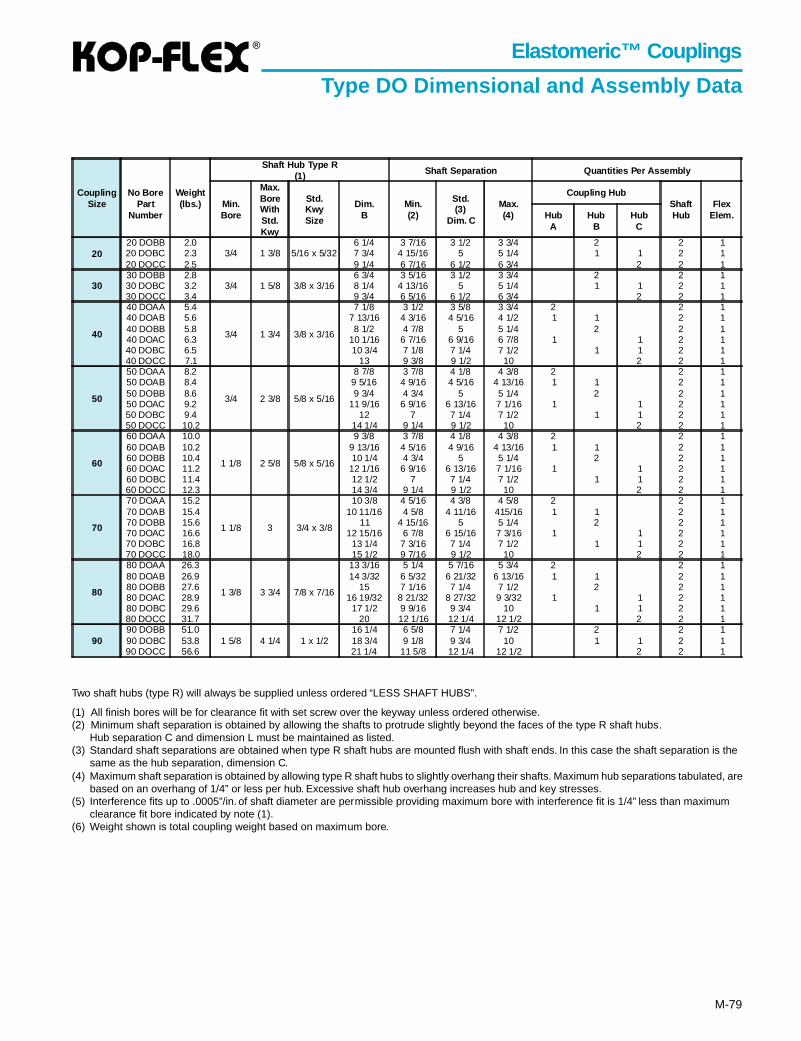
®
M-79
Elastomeric™ Couplings
Type DO Dimensional and Assembly Data
Two shaft hubs (type R) will always be supplied unless ordered “LESS SHAFT HUBS”.
(1) All finish bores will be for clearance fit with set screw over the keyway unless ordered otherwise.(2) Minimum shaft separation is obtained by allowing the shafts to protrude slightly beyond the faces of the type R shaft hubs.
Hub separation C and dimension L must be maintained as listed.(3) Standard shaft separations are obtained when type R shaft hubs are mounted flush with shaft ends. In this case the shaft separation is the
same as the hub separation, dimension C.(4) Maximum shaft separation is obtained by allowing type R shaft hubs to slightly overhang their shafts. Maximum hub separations tabulated, are
based on an overhang of 1/4” or less per hub. Excessive shaft hub overhang increases hub and key stresses.(5) Interference fits up to .0005”/in. of shaft diameter are permissible providing maximum bore with interference fit is 1/4” less than maximum
clearance fit bore indicated by note (1).(6) Weight shown is total coupling weight based on maximum bore.
CouplingSize
No BorePart
Number
Weight(lbs.)
Shaft Hub Type R(1) Shaft Separation Quantities Per Assembly
Min.Bore
Max.BoreWithStd.Kwy
Std.KwySize
Dim.B
Min.(2)
Std.(3)
Dim. C
Max.(4)
Coupling HubShaftHub
FlexElem.Hub
AHub
BHub
C
2020 DOBB 2.0
3/4 1 3/8 5/16 x 5/326 1/4 3 7/16 3 1/2 3 3/4 2 2 1
20 DOBC 2.3 7 3/4 4 15/16 5 5 1/4 1 1 2 120 DOCC 2.5 9 1/4 6 7/16 6 1/2 6 3/4 2 2 1
3030 DOBB 2.8
3/4 1 5/8 3/8 x 3/166 3/4 3 5/16 3 1/2 3 3/4 2 2 1
30 DOBC 3.2 8 1/4 4 13/16 5 5 1/4 1 1 2 130 DOCC 3.4 9 3/4 6 5/16 6 1/2 6 3/4 2 2 1
40
40 DOAA 5.4
3/4 1 3/4 3/8 x 3/16
7 1/8 3 1/2 3 5/8 3 3/4 2 2 140 DOAB 5.6 7 13/16 4 3/16 4 5/16 4 1/2 1 1 2 140 DOBB 5.8 8 1/2 4 7/8 5 5 1/4 2 2 140 DOAC 6.3 10 1/16 6 7/16 6 9/16 6 7/8 1 1 2 140 DOBC 6.5 10 3/4 7 1/8 7 1/4 7 1/2 1 1 2 140 DOCC 7.1 13 9 3/8 9 1/2 10 2 2 1
50
50 DOAA 8.2
3/4 2 3/8 5/8 x 5/16
8 7/8 3 7/8 4 1/8 4 3/8 2 2 150 DOAB 8.4 9 5/16 4 9/16 4 5/16 4 13/16 1 1 2 150 DOBB 8.6 9 3/4 4 3/4 5 5 1/4 2 2 150 DOAC 9.2 11 9/16 6 9/16 6 13/16 7 1/16 1 1 2 150 DOBC 9.4 12 7 7 1/4 7 1/2 1 1 2 150 DOCC 10.2 14 1/4 9 1/4 9 1/2 10 2 2 1
60
60 DOAA 10.0
1 1/8 2 5/8 5/8 x 5/16
9 3/8 3 7/8 4 1/8 4 3/8 2 2 160 DOAB 10.2 9 13/16 4 5/16 4 9/16 4 13/16 1 1 2 160 DOBB 10.4 10 1/4 4 3/4 5 5 1/4 2 2 160 DOAC 11.2 12 1/16 6 9/16 6 13/16 7 1/16 1 1 2 160 DOBC 11.4 12 1/2 7 7 1/4 7 1/2 1 1 2 160 DOCC 12.3 14 3/4 9 1/4 9 1/2 10 2 2 1
70
70 DOAA 15.2
1 1/8 3 3/4 x 3/8
10 3/8 4 5/16 4 3/8 4 5/8 2 2 170 DOAB 15.4 10 11/16 4 5/8 4 11/16 415/16 1 1 2 170 DOBB 15.6 11 4 15/16 5 5 1/4 2 2 170 DOAC 16.6 12 15/16 6 7/8 6 15/16 7 3/16 1 1 2 170 DOBC 16.8 13 1/4 7 3/16 7 1/4 7 1/2 1 1 2 170 DOCC 18.0 15 1/2 9 7/16 9 1/2 10 2 2 1
80
80 DOAA 26.3
1 3/8 3 3/4 7/8 x 7/16
13 3/16 5 1/4 5 7/16 5 3/4 2 2 180 DOAB 26.9 14 3/32 6 5/32 6 21/32 6 13/16 1 1 2 180 DOBB 27.6 15 7 1/16 7 1/4 7 1/2 2 2 180 DOAC 28.9 16 19/32 8 21/32 8 27/32 9 3/32 1 1 2 180 DOBC 29.6 17 1/2 9 9/16 9 3/4 10 1 1 2 180 DOCC 31.7 20 12 1/16 12 1/4 12 1/2 2 2 1
9090 DOBB 51.0
1 5/8 4 1/4 1 x 1/216 1/4 6 5/8 7 1/4 7 1/2 2 2 1
90 DOBC 53.8 18 3/4 9 1/8 9 3/4 10 1 1 2 190 DOCC 56.6 21 1/4 11 5/8 12 1/4 12 1/2 2 2 1
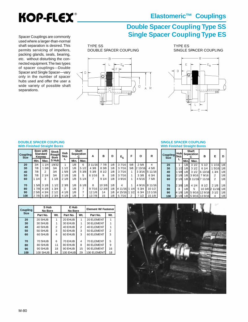
®
M-80
Elastomeric™ Couplings
Double Spacer Coupling Type SSSingle Spacer Coupling T ype ESSpacer Couplings are commonly
used where a larger-than-normalshaft separation is desired. Thispermits servicing of impellers,packing glands, seals, bearing,etc. without disturbing the con-nected equipment. The two typesof spacer couplings—DoubleSpacer and Single Spacer—varyonly in the number of spacerhubs used and offer the user awide variety of possible shaftseparations.
DOUBLE SPACER COUPLINGWith Finished Straight Bores
SINGLE SPACER COUPLINGWith Finished Straight Bores
TYPE SSDOUBLE SPACER COUPLING
TYPE ESSINGLE SPACER COUPLING
CouplingSize
Bore withStandardKeyway
StockRoughBore
S Hub
HubSep.
L
ShaftSeparation
C A B D ESF O R
Min. Max. Min. Max.20 3/4 1 1/4 19/32 1 1/8 6 3 11/16 7 7/8 1/8 3 7/16 5/8 2 5/8 430 7/8 1 5/8 3/4 1 1/2 1/8 5 1/2 4 3/8 8 3/8 1/8 3 7/16 5/8 2 13/16 4 5/840 7/8 2 3/4 1 5/8 1/8 5 3/8 5 3/8 8 1/2 1/8 3 7/16 1 3 3/16 5 11/1650 7/8 2 1/4 3/4 2 1/8 1/8 5 6 1/16 9 1/8 3 7/16 1 3 3/8 6 3/460 1 1/4 3 1 1/8 2 1/8 1/8 5 1/4 7 9 1/4 1/8 3 9/16 1 4 5/16 7 5/8
70 1 5/8 3 1/8 1 1/2 2 3/8 1/8 6 1/8 8 10 3/8 1/8 4 1 4 9/16 8 11/1680 1 7/8 4 1/8 1 3/4 3 1/8 7 9 7/16 12 3/8 1/8 4 11/16 1 1/4 5 3/4 10 1/290 2 5/8 4 3/4 2 1/2 4 1/8 1/8 7 12 1/8 14 1/8 4 15/16 1 1/2 6 3/4 13 1/16
100 2 7/8 5 3/8 2 3/4 4 1/8 1/8 7 13 7/8 15 1/8 5 7/16 2 7 1/2 15 1/8
CouplingSize
HubSep.
L
ShaftSeparation
C B E D
Min. Max.20 1 1/8 3 1/2 5 1/2 1 1/16 1/830 1 1/2 1/8 3 1/2 6 1/4 1 5/16 1/840 1 5/8 1/8 3 1/2 6 13/16 1 3/4 1/850 2 1/8 1/8 3 9/16 7 9/16 2 1/860 2 1/8 1/8 3 11/16 7 11/16 2 1/8
70 2 3/8 1/8 4 1/4 8 1/2 2 1/8 1/880 3 1/8 5 10 3/8 2 11/16 1/890 4 1/8 1/8 5 9/16 12 9/16 3 1/2 1/8100 4 1/8 1/8 5 9/16 13 9/16 4 1/8
CouplingSize
S HubNo Bore
E HubNo Bore Element W/ Fastener
Part No. Wt. Part No. Wt. Part No. Wt.
20 20 SHUB 1 20 EHUB 1 20 ELEMENT 130 30 SHUB 1 30 EHUB 1 30 ELEMENT 140 40 SHUB 2 40 EHUB 2 40 ELEMENT 150 50 SHUB 3 50 EHUB 3 50 ELEMENT 260 60 SHUB 4 60 EHUB 3 60 ELEMENT 3
70 70 SHUB 6 70 EHUB 4 70 ELEMENT 580 80 SHUB 11 80 EHUB 8 80 ELEMENT 990 90 SHUB 18 90 EHUB 15 90 ELEMENT 16
100 100 SHUB 34 100 EHUB 29 100 ELEMENT 18
SS
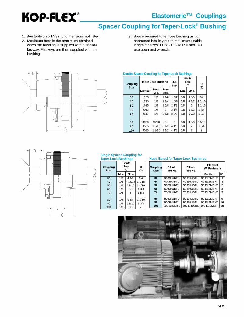
®
M-81
Elastomeric™ Couplings
Spacer Coupling for Taper-Lock ® Bushing1. See table on p. M-82 for dimensions not listed.2. Maximum bore is the maximum obtained
when the bushing is supplied with a shallowkeyway. Flat keys are then supplied with thebushing.
Double Spacer Coupling for Taper-Lock Bushings
Single Spacer Coupling forTaper-Lock Bushings
3. Space required to remove bushing usingshortened hex key cut to maximum usablelength for sizes 30 to 80. Sizes 90 and 100use open end wrench.
CouplingSize
ShaftSep.
CD
(3)Min. Max.
30 1/8 4 1/2 3/440 1/8 4 13/16 1 1/1650 1/8 4 9/16 1 1/1660 1/8 5 1/16 1 3/870 1/8 5 1 5/8
80 1/8 6 3/8 2 1/1690 1/8 5 9/16 1 3/4
100 1/8 5 9/16 2
CouplingSize
S HubPart No.
E HubPart No.
ElementW/ Fasteners
Part No. Wt.30 30 SHUBTL 30 EHUBTL 30 ELEMENT 140 40 SHUBTL 40 EHUBTL 40 ELEMENT 150 50 SHUBTL 50 EHUBTL 50 ELEMENT 260 60 SHUBTL 60 EHUBTL 60 ELEMENT 370 70 SHUBTL 70 EHUBTL 70 ELEMENT 5
80 80 SHUBTL 80 EHUBTL 80 ELEMENT 990 90 SHUBTL 90 EHUBTL 90 ELEMENT 16
100 100 SHUBTL 100 EHUBTL 100 ELEMENT 18
Hubs Bored for Taper-Lock Bushings
CouplingSize
Taper-Lock Bushing HubSep.
L
ShaftSep.
C D(3)
Number BoreMin.
BoreMax.
Min. Max.
30 1108 1/2 1 1/8 1 1/2 1/8 6 5/8 3/4
40 1215 1/2 1 1/4 1 5/8 1/8 6 1/2 1 1/16
50 1615 1/2 1 5/8 2 1/8 1/8 6 1 1/16
60 2012 1/2 2 2 1/8 1/8 6 1/2 1 3/8
70 2517 1/2 2 1/2 2 3/8 1/8 6 7/8 1 5/8
80 3020 15/16 3 3 1/8 8 3/8 2 1/16
90 3535 1 3/16 3 1/2 4 1/8 1/8 7 1 3/4
100 3535 1 3/16 3 1/2 4 1/8 1/8 7 2
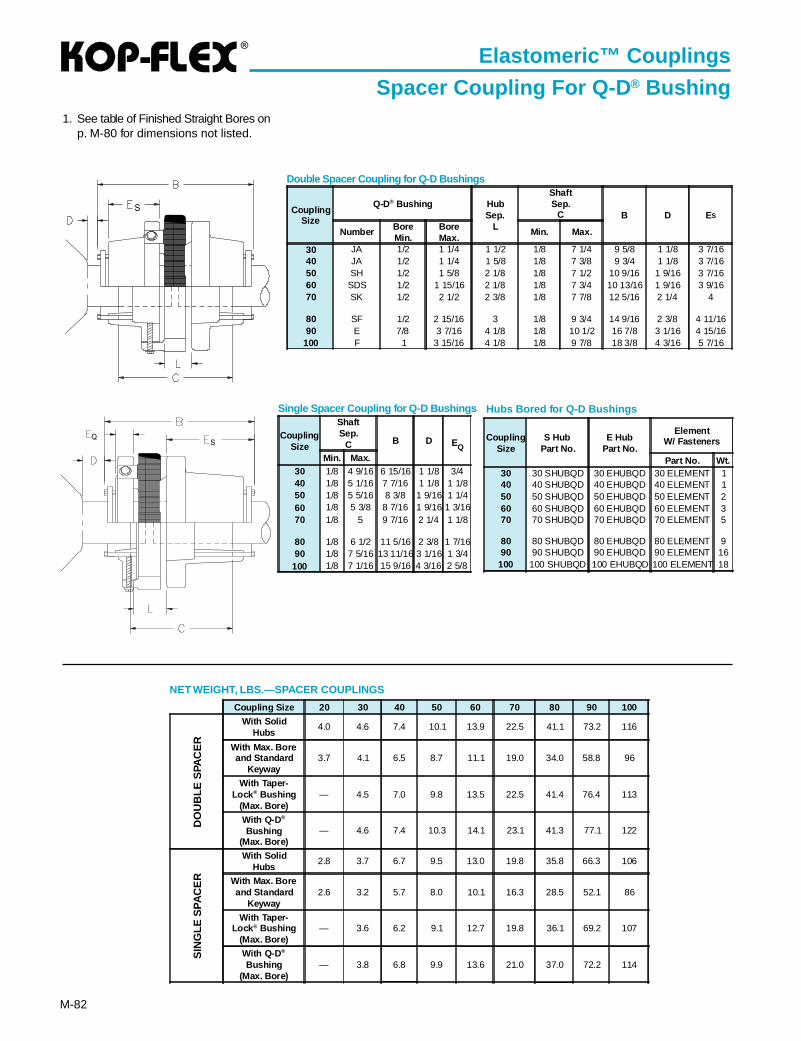
®
M-82
1. See table of Finished Straight Bores onp. M-80 for dimensions not listed.
Double Spacer Coupling for Q-D Bushings
Single Spacer Coupling for Q-D Bushings Hubs Bored for Q-D Bushings
NET WEIGHT, LBS.—SPACER COUPLINGS
CouplingSize
Q-D® Bushing HubSep.
L
ShaftSep.
C B D ES
Number BoreMin.
BoreMax.
Min. Max.
30 JA 1/2 1 1/4 1 1/2 1/8 7 1/4 9 5/8 1 1/8 3 7/1640 JA 1/2 1 1/4 1 5/8 1/8 7 3/8 9 3/4 1 1/8 3 7/1650 SH 1/2 1 5/8 2 1/8 1/8 7 1/2 10 9/16 1 9/16 3 7/1660 SDS 1/2 1 15/16 2 1/8 1/8 7 3/4 10 13/16 1 9/16 3 9/1670 SK 1/2 2 1/2 2 3/8 1/8 7 7/8 12 5/16 2 1/4 4
80 SF 1/2 2 15/16 3 1/8 9 3/4 14 9/16 2 3/8 4 11/1690 E 7/8 3 7/16 4 1/8 1/8 10 1/2 16 7/8 3 1/16 4 15/16
100 F 1 3 15/16 4 1/8 1/8 9 7/8 18 3/8 4 3/16 5 7/16
DO
UB
LE S
PAC
ER
SIN
GLE
SP
AC
ER
Elastomeric™ Couplings
Spacer Coupling For Q-D ® Bushing
Coupling Size 20 30 40 50 60 70 80 90 100
With SolidHubs
4.0 4.6 7.4 10.1 13.9 22.5 41.1 73.2 116
With Max. Boreand Standard
Keyway3.7 4.1 6.5 8.7 11.1 19.0 34.0 58.8 96
With Taper-Lock ® Bushing
(Max. Bore)— 4.5 7.0 9.8 13.5 22.5 41.4 76.4 113
With Q-D ®
Bushing(Max. Bore)
— 4.6 7.4 10.3 14.1 23.1 41.3 77.1 122
With SolidHubs
2.8 3.7 6.7 9.5 13.0 19.8 35.8 66.3 106
With Max. Boreand Standard
Keyway2.6 3.2 5.7 8.0 10.1 16.3 28.5 52.1 86
With Taper-Lock ® Bushing
(Max. Bore)— 3.6 6.2 9.1 12.7 19.8 36.1 69.2 107
With Q-D ®
Bushing(Max. Bore)
— 3.8 6.8 9.9 13.6 21.0 37.0 72.2 114
S
QS
CouplingSize
ShaftSep.
C B D EQMin. Max.
30 1/8 4 9/16 6 15/16 1 1/8 3/440 1/8 5 1/16 7 7/16 1 1/8 1 1/850 1/8 5 5/16 8 3/8 1 9/16 1 1/460 1/8 5 3/8 8 7/16 1 9/16 1 3/1670 1/8 5 9 7/16 2 1/4 1 1/8
80 1/8 6 1/2 11 5/16 2 3/8 1 7/1690 1/8 7 5/16 13 11/16 3 1/16 1 3/4
100 1/8 7 1/16 15 9/16 4 3/16 2 5/8
CouplingSize
S HubPart No.
E HubPart No.
ElementW/ Fasteners
Part No. Wt.30 30 SHUBQD 30 EHUBQD 30 ELEMENT 140 40 SHUBQD 40 EHUBQD 40 ELEMENT 150 50 SHUBQD 50 EHUBQD 50 ELEMENT 260 60 SHUBQD 60 EHUBQD 60 ELEMENT 370 70 SHUBQD 70 EHUBQD 70 ELEMENT 5
80 80 SHUBQD 80 EHUBQD 80 ELEMENT 990 90 SHUBQD 90 EHUBQD 90 ELEMENT 16
100 100 SHUBQD 100 EHUBQD 100 ELEMENT 18
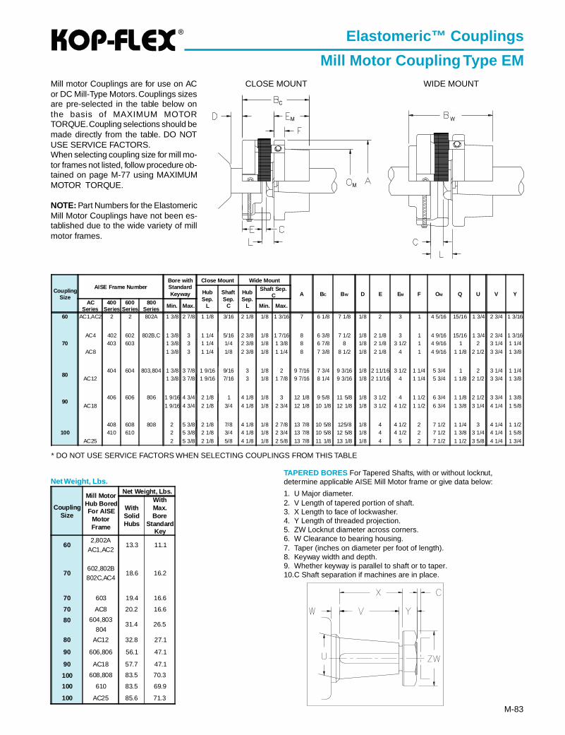
®
M-83
Elastomeric™ Couplings
Mill Motor Coupling Type EM
* DO NOT USE SERVICE FACTORS WHEN SELECTING COUPLINGS FROM THIS TABLE
Net Weight, Lbs.
Mill motor Couplings are for use on ACor DC Mill-Type Motors. Couplings sizesare pre-selected in the table below onthe basis of MAXIMUM MOTORTORQUE. Coupling selections should bemade directly from the table. DO NOTUSE SERVICE FACTORS.When selecting coupling size for mill mo-tor frames not listed, follow procedure ob-tained on page M-77 using MAXIMUMMOTOR TORQUE.
NOTE: Part Numbers for the ElastomericMill Motor Couplings have not been es-tablished due to the wide variety of millmotor frames.
CLOSE MOUNT WIDE MOUNT
CouplingSize
AISE Frame NumberBore withStandardKeyway
Close Mount Wide Mount
A BC BW D E EM F OM Q U V YHubSep.
L
ShaftSep.
C
HubSep.
L
Shaft Sep.C
ACSeries
400Series
600Series
800Series Min. Max. Min. Max.
60 AC1,AC2 2 2 802A 1 3/8 2 7/8 1 1/8 3/16 2 1/8 1/8 1 3/16 7 6 1/8 7 1/8 1/8 2 3 1 4 5/16 15/16 1 3/4 2 3/4 1 3/16
70AC4 402 602 802B,C 1 3/8 3 1 1/4 5/16 2 3/8 1/8 1 7/16 8 6 3/8 7 1/2 1/8 2 1/8 3 1 4 9/16 15/16 1 3/4 2 3/4 1 3/16
403 603 1 3/8 3 1 1/4 1/4 2 3/8 1/8 1 3/8 8 6 7/8 8 1/8 2 1/8 3 1/2 1 4 9/16 1 2 3 1/4 1 1/4
AC8 1 3/8 3 1 1/4 1/8 2 3/8 1/8 1 1/4 8 7 3/8 8 1/2 1/8 2 1/8 4 1 4 9/16 1 1/8 2 1/2 3 3/4 1 3/8
80404 604 803,804 1 3/8 3 7/8 1 9/16 9/16 3 1/8 2 9 7/16 7 3/4 9 3/16 1/8 2 11/16 3 1/2 1 1/4 5 3/4 1 2 3 1/4 1 1/4
AC12 1 3/8 3 7/8 1 9/16 7/16 3 1/8 1 7/8 9 7/16 8 1/4 9 3/16 1/8 2 11/16 4 1 1/4 5 3/4 1 1/8 2 1/2 3 3/4 1 3/8
90406 606 806 1 9/16 4 3/4 2 1/8 1 4 1/8 1/8 3 12 1/8 9 5/8 11 5/8 1/8 3 1/2 4 1 1/2 6 3/4 1 1/8 2 1/2 3 3/4 1 3/8
AC18 1 9/16 4 3/4 2 1/8 3/4 4 1/8 1/8 2 3/4 12 1/8 10 1/8 12 1/8 1/8 3 1/2 4 1/2 1 1/2 6 3/4 1 3/8 3 1/4 4 1/4 1 5/8
100408 608 808 2 5 3/8 2 1/8 7/8 4 1/8 1/8 2 7/8 13 7/8 10 5/8 125/8 1/8 4 4 1/2 2 7 1/2 1 1/4 3 4 1/4 1 1/2410 610 2 5 3/8 2 1/8 3/4 4 1/8 1/8 2 3/4 13 7/8 10 5/8 12 5/8 1/8 4 4 1/2 2 7 1/2 1 3/8 3 1/4 4 1/4 1 5/8
AC25 2 5 3/8 2 1/8 5/8 4 1/8 1/8 2 5/8 13 7/8 11 1/8 13 1/8 1/8 4 5 2 7 1/2 1 1/2 3 5/8 4 1/4 1 3/4
TAPERED BORES For Tapered Shafts, with or without locknut,determine applicable AISE Mill Motor frame or give data below:
1. U Major diameter.2. V Length of tapered portion of shaft.3. X Length to face of lockwasher.4. Y Length of threaded projection.5. ZW Locknut diameter across corners.6. W Clearance to bearing housing.7. Taper (inches on diameter per foot of length).8. Keyway width and depth.9. Whether keyway is parallel to shaft or to taper.10.C Shaft separation if machines are in place.
CouplingSize
Mill MotorHub BoredFor AISE
MotorFrame
Net Weight, Lbs.
WithSolidHubs
WithMax.Bore
StandardKey
602,802A
13.3 11.1AC1,AC2
70602,802B
18.6 16.2802C,AC4
70 603 19.4 16.6
70 AC8 20.2 16.6
80 604,80331.4 26.5
804
80 AC12 32.8 27.1
90 606,806 56.1 47.1
90 AC18 57.7 47.1
100 608,808 83.5 70.3
100 610 83.5 69.9
100 AC25 85.6 71.3
W
C
M
M
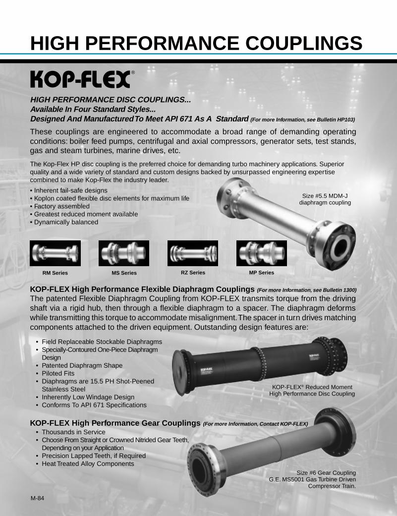
M-84
®
RM Series
These couplings are engineered to accommodate a broad range of demanding operatingconditions: boiler feed pumps, centrifugal and axial compressors, generator sets, test stands,gas and steam turbines, marine drives, etc.
The Kop-Flex HP disc coupling is the preferred choice for demanding turbo machinery applications. Superiorquality and a wide variety of standard and custom designs backed by unsurpassed engineering expertisecombined to make Kop-Flex the industry leader.
• Inherent fail-safe designs• Koplon coated flexible disc elements for maximum life• Factory assembled• Greatest reduced moment available• Dynamically balanced
KOP-FLEX High Performance Flexible Diaphragm Couplings (For more Information, see Bulletin 1300)
The patented Flexible Diaphragm Coupling from KOP-FLEX transmits torque from the drivingshaft via a rigid hub, then through a flexible diaphragm to a spacer. The diaphragm deformswhile transmitting this torque to accommodate misalignment. The spacer in turn drives matchingcomponents attached to the driven equipment. Outstanding design features are:
• Field Replaceable Stockable Diaphragms• Specially-Contoured One-Piece Diaphragm
Design• Patented Diaphragm Shape• Piloted Fits• Diaphragms are 15.5 PH Shot-Peened
Stainless Steel• Inherently Low Windage Design• Conforms To API 671 Specifications
HIGH PERFORMANCE DISC COUPLINGS...Available In Four Standard Styles...Designed And Manufactured To Meet API 671 As A Standard (For more Information, see Bulletin HP103)
MS Series RZ Series MP Series
KOP-FLEX® Reduced MomentHigh Performance Disc Coupling
Size #5.5 MDM-Jdiaphragm coupling
KOP-FLEX High Performance Gear Couplings (For more Information, Contact KOP-FLEX)
• Thousands in Service• Choose From Straight or Crowned Nitrided Gear Teeth,
Depending on your Application• Precision Lapped Teeth, if Required• Heat Treated Alloy Components
Size #6 Gear CouplingG.E. MS5001 Gas Turbine Driven
Compressor Train.
HIGH PERFORMANCE COUPLINGS
M-85
MAX-C®
Resilient Couplings
Index:Page
HOW TO ORDER ..................................... M-89Technical Advantages ..................... M-76, M-87Service Factors ........................................ M-88Selection Procedure ................................. M-89Max-C Type K2 ......................................... M-90Max-C Type UB ........................................ M-91Limited End Float Coupling ...................... M-92Floating Shaft Coupling ............................ M-93Spacer Coupling ....................................... M-93Max-C Type CB & WB
For Engineered Applications ............... M-94
High Torque,Maintenance-FreeCoupling
Absorb HarmfulShock Loads
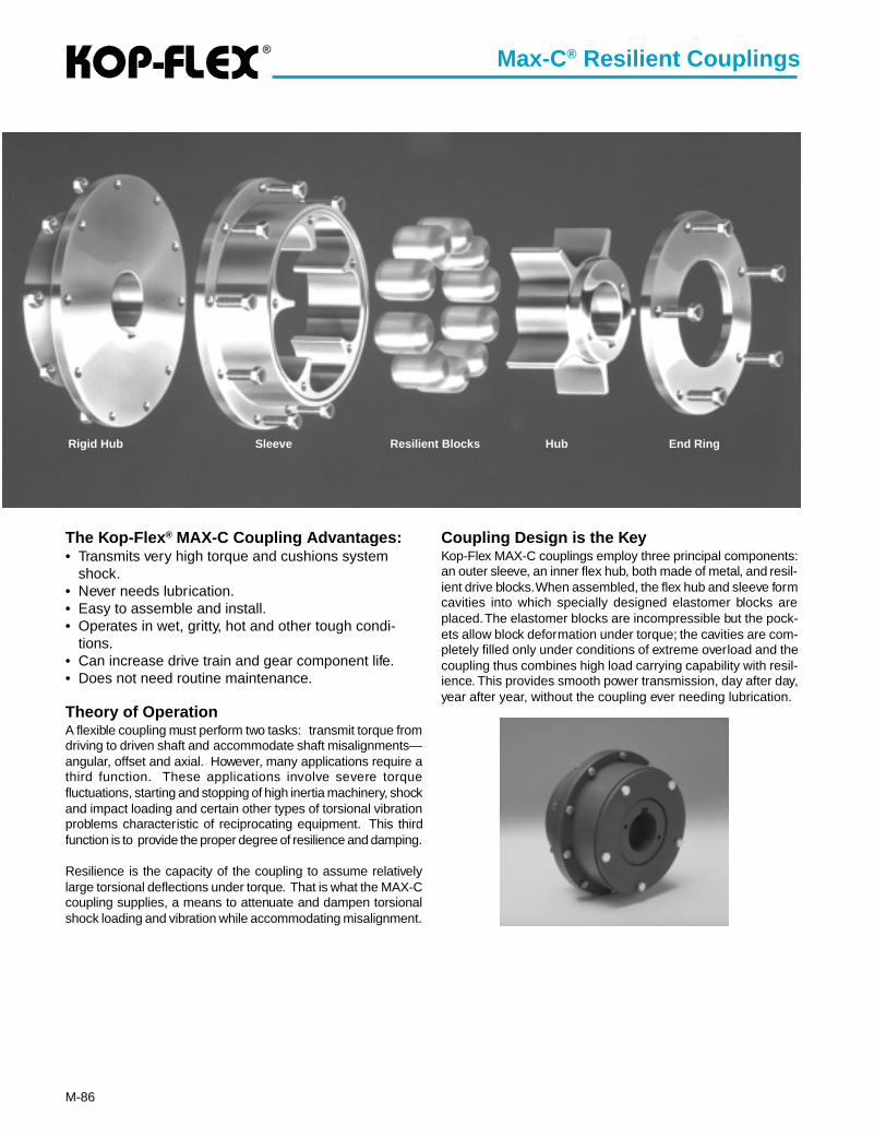
®
M-86
Coupling Design is the KeyKop-Flex MAX-C couplings employ three principal components:an outer sleeve, an inner flex hub, both made of metal, and resil-ient drive blocks. When assembled, the flex hub and sleeve formcavities into which specially designed elastomer blocks areplaced. The elastomer blocks are incompressible but the pock-ets allow block deformation under torque; the cavities are com-pletely filled only under conditions of extreme overload and thecoupling thus combines high load carrying capability with resil-ience. This provides smooth power transmission, day after day,year after year, without the coupling ever needing lubrication.
The Kop-Flex ® MAX-C Coupling Advantages:• Transmits very high torque and cushions system
shock.• Never needs lubrication.• Easy to assemble and install.• Operates in wet, gritty, hot and other tough condi-
tions.• Can increase drive train and gear component life.• Does not need routine maintenance.
Theory of OperationA flexible coupling must perform two tasks: transmit torque fromdriving to driven shaft and accommodate shaft misalignments—angular, offset and axial. However, many applications require athird function. These applications involve severe torquefluctuations, starting and stopping of high inertia machinery, shockand impact loading and certain other types of torsional vibrationproblems characteristic of reciprocating equipment. This thirdfunction is to provide the proper degree of resilience and damping.
Resilience is the capacity of the coupling to assume relativelylarge torsional deflections under torque. That is what the MAX-Ccoupling supplies, a means to attenuate and dampen torsionalshock loading and vibration while accommodating misalignment.
Rigid Hub Sleeve Resilient Blocks Hub End Ring
Max-C® Resilient Couplings
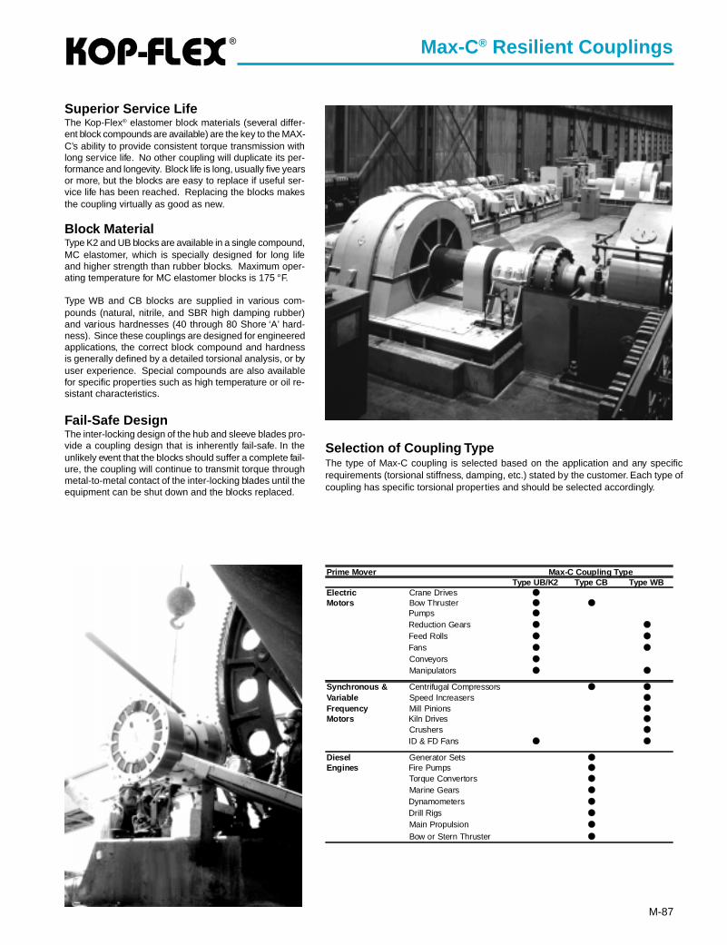
®
M-87
Selection of Coupling TypeThe type of Max-C coupling is selected based on the application and any specificrequirements (torsional stiffness, damping, etc.) stated by the customer. Each type ofcoupling has specific torsional properties and should be selected accordingly.
Superior Service LifeThe Kop-Flex® elastomer block materials (several differ-ent block compounds are available) are the key to the MAX-C’s ability to provide consistent torque transmission withlong service life. No other coupling will duplicate its per-formance and longevity. Block life is long, usually five yearsor more, but the blocks are easy to replace if useful ser-vice life has been reached. Replacing the blocks makesthe coupling virtually as good as new.
Block MaterialType K2 and UB blocks are available in a single compound,MC elastomer, which is specially designed for long lifeand higher strength than rubber blocks. Maximum oper-ating temperature for MC elastomer blocks is 175 °F.
Type WB and CB blocks are supplied in various com-pounds (natural, nitrile, and SBR high damping rubber)and various hardnesses (40 through 80 Shore ‘A’ hard-ness). Since these couplings are designed for engineeredapplications, the correct block compound and hardnessis generally defined by a detailed torsional analysis, or byuser experience. Special compounds are also availablefor specific properties such as high temperature or oil re-sistant characteristics.
Fail-Safe DesignThe inter-locking design of the hub and sleeve blades pro-vide a coupling design that is inherently fail-safe. In theunlikely event that the blocks should suffer a complete fail-ure, the coupling will continue to transmit torque throughmetal-to-metal contact of the inter-locking blades until theequipment can be shut down and the blocks replaced.
Max-C® Resilient Couplings
Prime Mover Max-C Coupling TypeType UB/K2 Type CB Type WB
Electric Crane Drives ●
Motors Bow Thruster ● ●
Pumps ●
Reduction Gears ● ●
Feed Rolls ● ●
Fans ● ●
Conveyors ●
Manipulators ● ●
Synchronous & Centrifugal Compressors ● ●
Variable Speed Increasers ●
Frequency Mill Pinions ●
Motors Kiln Drives ●
Crushers ●
ID & FD Fans ● ●
Diesel Generator Sets ●
Engines Fire Pumps ●
Torque Convertors ●
Marine Gears ●
Dynamometers ●
Drill Rigs ●
Main Propulsion ●
Bow or Stern Thruster ●
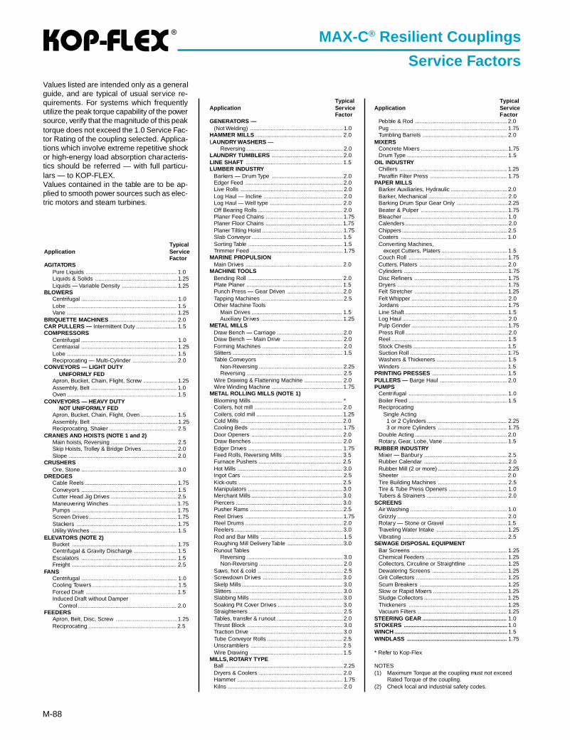
®
M-88
TypicalApplication Ser vice
FactorAGITATORS
Pure Liquids .......................................................... 1.0Liquids & Solids .................................................... 1.25Liquids — Variable Density ................................... 1.25
BLOWERSCentrifugal ............................................................. 1.0Lobe ...................................................................... 1.5Vane ...................................................................... 1.25
BRIQUETTE MACHINES ........................................... 2.0CAR PULLERS — Intermittent Duty .......................... 1.5COMPRESSORS
Centrifugal ............................................................. 1.0Centriaxial ............................................................. 1.25Lobe ...................................................................... 1.5Reciprocating — Multi-Cylinder ............................ 2.0
CONVEYORS — LIGHT DUTY UNIFORMLY FEDApron, Bucket, Chain, Flight, Screw ..................... 1.25Assembly, Belt ....................................................... 1.0Oven ...................................................................... 1.5
CONVEYORS — HEAVY DUTY NOT UNIFORMLY FEDApron, Bucket, Chain, Flight, Oven ....................... 1.5Assembly, Belt ....................................................... 1.25Reciprocating, Shaker ........................................... 2.5
CRANES AND HOISTS (NOTE 1 and 2)Main hoists, Reversing .......................................... 2.5Skip Hoists, Trolley & Bridge Drives ...................... 2.0Slope ..................................................................... 2.0
CRUSHERSOre, Stone ............................................................. 3.0
DREDGESCable Reels ........................................................... 1.75Conveyors ............................................................. 1.5Cutter Head Jig Drives .......................................... 2.5Maneuvering Winches ........................................... 1.75Pumps ................................................................... 1.75Screen Drives ........................................................ 1.75Stackers ................................................................ 1.75Utility Winches ....................................................... 1.5
ELEVATORS (NOTE 2)Bucket ................................................................... 1.75Centrifugal & Gravity Discharge ........................... 1.5Escalators ............................................................. 1.5Freight ................................................................... 2.5
FANSCentrifugal ............................................................. 1.0Cooling Towers ...................................................... 1.5Forced Draft .......................................................... 1.5Induced Draft without Damper Control ............................................................... 2.0
FEEDERSApron, Belt, Disc, Screw ....................................... 1.25Reciprocating ........................................................ 2.5
TypicalApplication Ser vice
FactorGENERATORS —
(Not Welding) ........................................................... 1.0HAMMER MILLS ........................................................ 2.0LAUNDRY WASHERS —
Reversing ............................................................. 2.0LAUNDRY TUMBLERS ............................................. 2.0LINE SHAFT .............................................................. 1.5LUMBER INDUSTRY
Barkers — Drum Type ............................................. 2.0Edger Feed .............................................................. 2.0Live Rolls ................................................................. 2.0Log Haul — Incline .................................................. 2.0Log Haul — Well type .............................................. 2.0Off Bearing Rolls ...................................................... 2.0Planer Feed Chains ................................................. 1.75Planer Floor Chains ................................................. 1.75Planer Tilting Hoist ................................................... 1.75Slab Conveyor .......................................................... 1.5Sorting Table ............................................................ 1.5Trimmer Feed ........................................................... 1.75
MARINE PROPULSIONMain Drives .............................................................. 2.0
MACHINE TOOLSBending Roll ............................................................ 2.0Plate Planer ............................................................. 1.5Punch Press — Gear Driven ................................... 2.0Tapping Machines .................................................... 2.5Other Machine Tools Main Drives .......................................................... 1.5 Auxiliary Drives .................................................... 1.25
METAL MILLSDraw Bench — Carriage .......................................... 2.0Draw Bench — Main Drive ...................................... 2.0Forming Machines ................................................... 2.0Slitters ...................................................................... 1.5Table Conveyors Non-Reversing ..................................................... 2.25 Reversing ............................................................. 2.5Wire Drawing & Flattening Machine ........................ 2.0Wire Winding Machine ............................................. 1.75
METAL ROLLING MILLS (NOTE 1)Blooming Mills .......................................................... *Coilers, hot mill ........................................................ 2.0Coilers, cold mill ....................................................... 1.25Cold Mills ................................................................. 2.0Cooling Beds ........................................................... 1.75Door Openers .......................................................... 2.0Draw Benches .......................................................... 2.0Edger Drives ............................................................ 1.75Feed Rolls, Reversing Mills ..................................... 3.5Furnace Pushers ..................................................... 2.5Hot Mills ................................................................... 3.0Ingot Cars ................................................................ 2.5Kick-outs .................................................................. 2.5Manipulators ............................................................ 3.0Merchant Mills .......................................................... 3.0Piercers .................................................................... 3.0Pusher Rams ........................................................... 2.5Reel Drives .............................................................. 1.75Reel Drums .............................................................. 2.0Reelers ..................................................................... 3.0Rod and Bar Mills .................................................... 1.5Roughing Mill Delivery Table ................................... 3.0Runout Tables Reversing ............................................................. 3.0 Non-Reversing ..................................................... 2.0Saws, hot & cold ...................................................... 2.5Screwdown Drives ................................................... 3.0Skelp Mills ................................................................ 3.0Slitters ...................................................................... 3.0Slabbing Mills ........................................................... 3.0Soaking Pit Cover Drives ......................................... 3.0Straighteners ............................................................ 2.5Tables, transfer & runout .......................................... 2.0Thrust Block ............................................................. 3.0Traction Drive ........................................................... 3.0Tube Conveyor Rolls ................................................ 2.5Unscramblers ........................................................... 2.5Wire Drawing ........................................................... 1.5
MILLS, ROTARY TYPEBall ........................................................................... 2.25Dryers & Coolers ..................................................... 2.0Hammer ................................................................... 1.75Kilns ......................................................................... 2.0
TypicalApplication Ser vice
FactorPebble & Rod ........................................................... 2.0Pug ........................................................................... 1.75Tumbling Barrels ...................................................... 2.0
MIXERSConcrete Mixers ....................................................... 1.75Drum Type ................................................................ 1.5
OIL INDUSTRYChillers ..................................................................... 1.25Paraffin Filter Press ................................................. 1.75
PAPER MILLSBarker Auxiliaries, Hydraulic .................................... 2.0Barker, Mechanical .................................................. 2.0Barking Drum Spur Gear Only ................................ 2.25Beater & Pulper ....................................................... 1.75Bleacher ................................................................... 1.0Calenders ................................................................. 2.0Chippers ................................................................... 2.5Coaters .................................................................... 1.0Converting Machines, except Cutters, Platers .......................................... 1.5Couch Roll ............................................................... 1.75Cutters, Platers ........................................................ 2.0Cylinders .................................................................. 1.75Disc Refiners ........................................................... 1.75Dryers ...................................................................... 1.75Felt Stretcher ........................................................... 1.25Felt Whipper ............................................................. 2.0Jordans .................................................................... 1.75Line Shaft ................................................................. 1.5Log Haul ................................................................... 2.0Pulp Grinder ............................................................. 1.75Press Roll ................................................................. 2.0Reel .......................................................................... 1.5Stock Chests ............................................................ 1.5Suction Roll .............................................................. 1.75Washers & Thickeners ............................................. 1.5Winders .................................................................... 1.5
PRINTING PRESSES ................................................ 1.5PULLERS — Barge Haul ........................................... 2.0PUMPS
Centrifugal ............................................................... 1.0Boiler Feed ............................................................... 1.5Reciprocating Single Acting 1 or 2 Cylinders ................................................... 2.25 3 or more Cylinders ............................................ 1.75Double Acting ........................................................... 2.0Rotary, Gear, Lobe, Vane ......................................... 1.5
RUBBER INDUSTRYMixer — Banbury ..................................................... 2.5Rubber Calendar ..................................................... 2.0Rubber Mill (2 or more) ............................................ 2.25Sheeter .................................................................... 2.0Tire Building Machines ............................................ 2.5Tire & Tube Press Openers ..................................... 1.0Tubers & Strainers ................................................... 2.0
SCREENSAir Washing .............................................................. 1.0Grizzly ...................................................................... 2.0Rotary — Stone or Gravel ....................................... 1.5Traveling Water Intake ............................................. 1.25Vibrating ................................................................... 2.5
SEWAGE DISPOSAL EQUIPMENTBar Screens ............................................................. 1.25Chemical Feeders .................................................... 1.25Collectors, Circuline or Straightline ......................... 1.25Dewatering Screens ................................................ 1.25Grit Collectors .......................................................... 1.25Scum Breakers ........................................................ 1.25Slow or Rapid Mixers ............................................... 1.25Sludge Collectors ..................................................... 1.25Thickeners ............................................................... 1.25Vacuum Filters ......................................................... 1.25
STEERING GEAR ...................................................... 1.0STOKERS .................................................................. 1.0WINCH ........................................................................ 1.5WINDLASS ................................................................ 1.75
* Refer to Kop-Flex
NOTES(1) Maximum Torque at the coupling must not exceed
Rated Torque of the coupling.(2) Check local and industrial safety codes.
MAX-C® Resilient Couplings
Service FactorsValues listed are intended only as a generalguide, and are typical of usual service re-quirements. For systems which frequentlyutilize the peak torque capability of the powersource, verify that the magnitude of this peaktorque does not exceed the 1.0 Service Fac-tor Rating of the coupling selected. Applica-tions which involve extreme repetitive shockor high-energy load absorption characteris-tics should be referred — with full particu-lars — to KOP-FLEX.Values contained in the table are to be ap-plied to smooth power sources such as elec-tric motors and steam turbines.
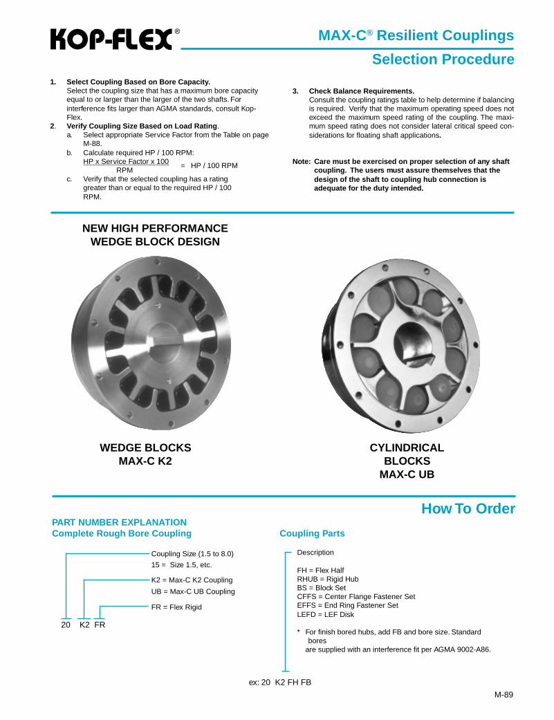
®
M-89
1. Select Coupling Based on Bore Capacity.Select the coupling size that has a maximum bore capacityequal to or larger than the larger of the two shafts. Forinterference fits larger than AGMA standards, consult Kop-Flex.
2. Verify Coupling Size Based on Load Rating .a. Select appropriate Service Factor from the Table on page
M-88.b. Calculate required HP / 100 RPM:
HP x Service Factor x 100RPM
= HP / 100 RPM
c. Verify that the selected coupling has a ratinggreater than or equal to the required HP / 100RPM.
3. Check Balance Requirements.Consult the coupling ratings table to help determine if balancingis required. Verify that the maximum operating speed does notexceed the maximum speed rating of the coupling. The maxi-mum speed rating does not consider lateral critical speed con-siderations for floating shaft applications.
Note: Care must be exercised on proper selection of any shaftcoupling. The users must assure themselves that thedesign of the shaft to coupling hub connection isadequate for the duty intended.
Description
FH = Flex HalfRHUB = Rigid HubBS = Block SetCFFS = Center Flange Fastener SetEFFS = End Ring Fastener SetLEFD = LEF Disk
* For finish bored hubs, add FB and bore size. Standardbores
are supplied with an interference fit per AGMA 9002-A86.
PART NUMBER EXPLANATIONComplete Rough Bore Coupling
Coupling Size (1.5 to 8.0)
15 = Size 1.5, etc.
K2 = Max-C K2 Coupling
UB = Max-C UB Coupling
FR = Flex Rigid
Coupling Parts
20 K2 FR
ex: 20 K2 FH FB
MAX-C® Resilient Couplings
Selection Procedure
WEDGE BLOCKSMAX-C K2
CYLINDRICALBLOCKS
MAX-C UB
How To Order
NEW HIGH PERFORMANCEWEDGE BLOCK DESIGN
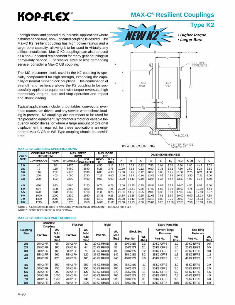
®
M-90
MAX-C® Resilient Couplings
Type K2
MAX-C K2 COUPLING SPECIFICATIONS
For high shock and general duty industrial applications wherea maintenance-free, non-lubricated coupling is desired. TheMax-C K2 resilient coupling has high power ratings and alarge bore capacity, allowing it to be used in virtually anydifficult installation. Max-C K2 couplings can also be usedas a non-lubricated replacement for many gear couplings inheavy-duty service. For smaller sizes or less demandingservice, consider a Max-C UB coupling.
The MC elastomer block used in the K2 coupling is spe-cially compounded for high strength, exceeding the capa-bility of normal rubber block couplings. This combination ofstrength and resilience allows the K2 coupling to be suc-cessfully applied to equipment with torque reversals, highmomentary torques, start and stop operation and impactand shock loading.
Typical applications include runout tables, conveyors, over-head cranes, fan drives, and any service where shock load-ing is present. K2 couplings are not meant to be used forreciprocating equipment, synchronous motor or variable fre-quency motor drives, or where a large amount of torsionaldisplacement is required; for these applications an engi-neered Max-C CB or WB Type coupling should be consid-ered.
CPLGSIZE
COUPLING CAPACITYHP/100RPM
MAX. SPEED(RPM)
MAX. BORE(IN.) DIMENSIONS (INCHES)
CONTINUOUS PEAK BALANCED NOTBALANCED
RIGID(1)
FLEXHUB A B C G E ER F(1) K (2) O U
2.0 45 90 6370 4250 4.50 3.13 9.00 6.03 0.12 7.50 2.94 3.00 6.50 2.00 4.43 3.032.5 79 158 5460 3640 5.25 3.75 10.50 7.13 0.12 9.00 3.38 3.62 7.50 2.50 5.29 3.513.0 116 232 4770 3180 6.00 4.38 12.00 8.25 0.12 10.50 3.88 4.25 8.50 2.75 6.21 4.003.5 200 400 4090 2730 7.25 5.00 14.00 9.88 0.16 12.06 4.88 4.88 10.50 3.50 7.21 5.004.0 300 600 3600 2400 9.63 6.00 16.00 11.12 0.19 13.94 5.38 5.62 13.50 4.00 8.36 5.50
4.5 420 840 3180 2120 9.75 6.75 18.00 12.25 0.25 15.94 5.88 6.25 14.00 4.50 9.59 6.005.0 574 1148 2860 1910 10.50 7.25 20.00 13.81 0.25 17.50 6.62 7.00 15.00 4.75 10.38 6.815.5 670 1340 2560 1710 11.88 8.25 22.63 14.37 0.25 19.88 6.38 8.00 17.00 4.63 12.13 6.376.0 1000 2000 2330 1550 13.38 9.25 24.88 16.38 0.25 21.62 7.88 8.50 19.00 6.00 13.13 7.887.0 1300 2600 2150 1430 14.13 10.00 26.88 18.12 0.50 23.12 8.88 9.25 20.00 7.13 14.13 8.878.0 1745 3490 1970 1310 14.88 11.00 29.38 19.25 0.50 25.62 9.25 10.00 22.50 7.50 16.63 9.25
NOTE 1 - A LARGER RIGID BORE IS AVAILABLE BY INCREASING DIMENSION F - CONSULT KOP-FLEXNOTE 2 - SPACE NEEDED FOR BLOCK REMOVAL.
CouplingSize
CompleteCoupling
Flex Half Rigid Spare Parts Kits
Part No.
Wt.SolidHubs(lbs.)
Part No.
Wt.SolidHubs(lbs.)
Part No.Wt.
Solid(lbs.)
Block SetCenter Flange
FastenersEnd RingFasteners
Part No.Wt.
(lbs.) Part No.Wt.
(lbs.) Part No.Wt.
(lbs.)2.0 20 K2 FR 66 20 K2 FH 31 20 K2 RHUB 35 20 K2 BS 1.2 20 K2 CFFS 1.0 20 K2 EFFS 0.52.5 25 K2 FR 100 25 K2 FH 44 25 K2 RHUB 56 25 K2 BS 2.1 25 K2 CFFS 1.0 25 K2 EFFS 0.53.0 30 K2 FR 160 30 K2 FH 76 30 K2 RHUB 84 30 K2 BS 3.2 30 K2 CFFS 1.5 30 K2 EFFS 0.83.5 35 K2 FR 260 35 K2 FH 120 35 K2 RHUB 140 35 K2 BS 5.3 35 K2 CFFS 1.5 35 K2 EFFS 1.24.0 40 K2 FR 420 40 K2 FH 180 40 K2 RHUB 240 40 K2 BS 8.0 40 K2 CFFS 1.5 40 K2 EFFS 1.2
4.5 45 K2 FR 550 45 K2 FH 250 45 K2 RHUB 300 45 K2 BS 11 45 K2 CFFS 3.0 45 K2 EFFS 2.05.0 50 K2 FR 750 50 K2 FH 350 50 K2 RHUB 400 50 K2 BS 15 50 K2 CFFS 5.0 50 K2 EFFS 2.05.5 55 K2 FR 990 55 K2 FH 420 55 K2 RHUB 570 55 K2 BS 18 55 K2 CFFS 5.0 55 K2 EFFS 4.56.0 60 K2 FR 1400 60 K2 FH 640 60 K2 RHUB 760 60 K2 BS 26 60 K2 CFFS 7.5 60 K2 EFFS 4.57.0 70 K2 FR 1700 70 K2 FH 780 70 K2 RHUB 920 70 K2 BS 36 70 K2 CFFS 9.0 70 K2 EFFS 6.08.0 80 K2 FR 2200 80 K2 FH 1000 80 K2 RHUB 1200 80 K2 BS 43 80 K2 CFFS 10.5 80 K2 EFFS 6.0
MAX-C K2 COUPLING PART NUMBERS
K2 & UB COUPLING
• Higher Torque• Larger Bore
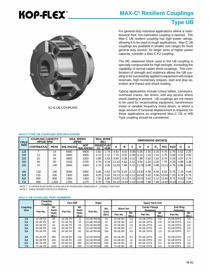
®
M-91
MAX-C® Resilient Couplings
Type UB
MAX-C TYPE UB COUPLING SPECIFICATIONS
For general duty industrial applications where a main-tenance-free, non-lubricated coupling is desired. TheMax-C UB resilient coupling has high power ratings,allowing it to be used in tough applications. Max-C UBcouplings are available in smaller size ranges for mostgeneral duty service, for larger sizes or higher powercapacity, consider a Max-C K2 coupling.
The MC elastomer block used in the UB coupling isspecially compounded for high strength, exceeding thecapability of normal rubber block couplings. This com-bination of strength and resilience allows the UB cou-pling to be successfully applied to equipment with torquereversals, high momentary torques, start and stop op-eration and impact and shock loading.
Typical applications include runout tables, conveyors,overhead cranes, fan drives, and any service whereshock loading is present. UB couplings are not meantto be used for reciprocating equipment, synchronousmotor or variable frequency motor drives, or where alarge amount of torsional displacement is required; forthese applications an engineered Max-C CB or WBType coupling should be considered.
NOTE 1 - A LARGER RIGID BORE IS AVAILABLE BY INCREASING DIMENSION F - CONSULT KOP-FLEXNOTE 2 - SPACE NEEDED FOR BLOCK REMOVAL.
CouplingSize
CompleteCoupling Flex Half Rigid Spare Parts Kits
Part No.
Wt.SolidHubs(lbs.)
Part No.
Wt.SolidHubs(lbs.)
Part No.Wt.
Solid(lbs.)
Block Set Center FlangeFasteners
End RingFasteners
Part No.Wt.
(lbs.) Part No.Wt.
(lbs.) Part No.Wt.
(lbs.)1.5 15 UB FR 25 15 UB FH 11 15 UB RHUB 14 15 UB BS 0.4 15 UB CFFS 0.8 15 UB EFFS 0.42.0 20 UB FR 40 20 UB FH 18 20 UB RHUB 22 20 UB BS 0.8 20 UB CFFS 0.8 20 UB EFFS 0.52.5 25 UB FR 62 25 UB FH 28 25 UB RHUB 34 25 UB BS 1.5 25 UB CFFS 1.0 25 UB EFFS 0.53.0 30 UB FR 104 30 UB FH 50 30 UB RHUB 54 30 UB BS 2.7 30 UB CFFS 1.0 30 UB EFFS 0.53.5 35 UB FR 180 35 UB FH 80 35 UB RHUB 100 35 UB BS 4.5 35 UB CFFS 1.5 35 UB EFFS 0.7
4.0 40 UB FR 280 40 UB FH 140 40 UB RHUB 140 40 UB BS 8.1 40 UB CFFS 1.5 40 UB EFFS 1.05.0 50 UB FR 420 50 UB FH 220 50 UB RHUB 200 50 UB BS 14 50 UB CFFS 3.0 50 UB EFFS 1.46.0 60 UB FR 740 60 UB FH 450 60 UB RHUB 290 60 UB BS 25 60 UB CFFS 5.5 60 UB EFFS 3.07.0 70 UB FR 1030 70 UB FH 590 70 UB RHUB 440 70 UB BS 38 70 UB CFFS 6.0 70 UB EFFS 3.0
MAX-C UB COUPLING PART NUMBERS
CPLGSIZE
COUPLING CAPACITYHP/100 RPM
MAX. SPEED(RPM)
MAX. BORE(IN.) DIMENSIONS (INCHES)
CONTINUOUS PEAK BALANCED NOTBALANCED
RIGID(1)
FLEXHUB A B C G E E R F(1) K(2) O U
1.5 7 14 6900 4600 2.62 1.75 6.62 4.41 0.09 5.00 2.16 2.16 4.75 2.75 2.62 2.252.0 12 24 5900 3930 3.12 2.12 7.75 4.91 0.09 6.12 2.41 2.41 5.75 3.00 3.22 2.502.5 22 44 4800 3200 3.88 2.62 9.50 5.38 0.12 7.88 2.62 2.62 6.75 3.25 3.97 2.753.0 40 80 4100 2730 4.75 3.19 11.12 6.62 0.12 9.50 3.25 3.25 7.75 4.25 4.88 3.383.5 70 140 3600 2400 5.75 3.81 13.25 7.88 0.12 11.25 3.88 3.88 10.12 4.75 5.88 4.00
4.0 120 240 3000 2000 5.00 4.62 15.75 9.25 0.12 13.62 4.56 4.56 8.00 5.75 7.19 4.695.0 215 430 2400 1600 6.25 5.62 19.12 11.31 0.12 16.50 5.62 5.56 10.00 7.25 8.78 5.756.0 400 800 1950 1300 7.50 6.88 23.50 13.12 0.19 20.25 6.81 6.12 12.00 8.75 10.62 7.007.0 600 1,200 1760 1170 8.75 7.81 26.12 15.94 0.19 22.88 7.88 7.88 14.00 10.25 12.12 8.06
K2 & UB COUPLING
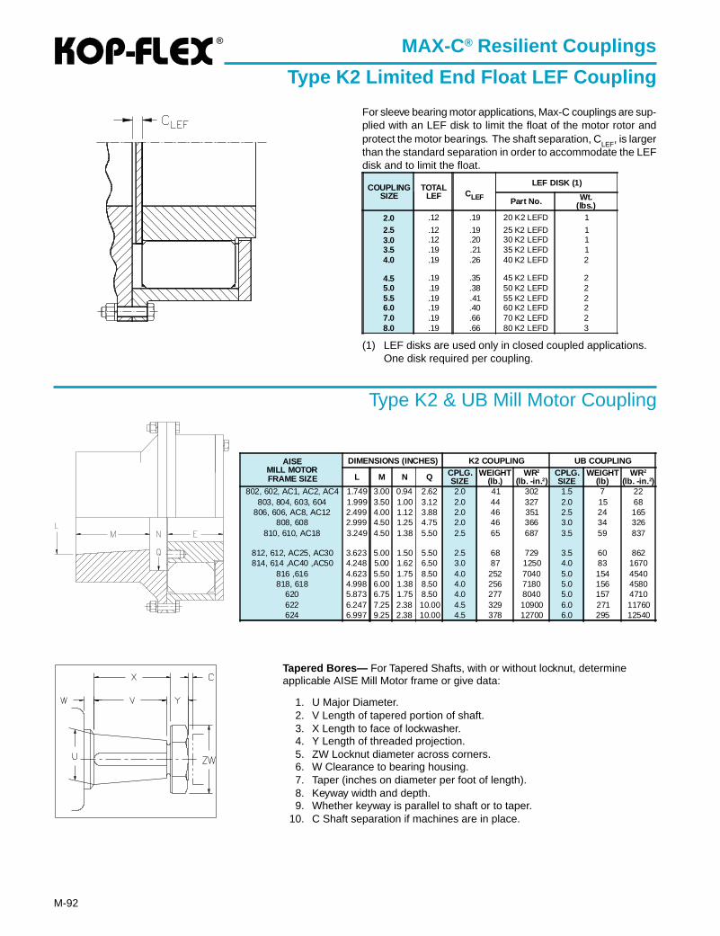
®
M-92
MAX-C® Resilient Couplings
Type K2 Limited End Float LEF Coupling
For sleeve bearing motor applications, Max-C couplings are sup-plied with an LEF disk to limit the float of the motor rotor andprotect the motor bearings. The shaft separation, C
LEF, is larger
than the standard separation in order to accommodate the LEFdisk and to limit the float.
(1) LEF disks are used only in closed coupled applications.One disk required per coupling.
Tapered Bores— For Tapered Shafts, with or without locknut, determineapplicable AISE Mill Motor frame or give data:
1. U Major Diameter.2. V Length of tapered portion of shaft.3. X Length to face of lockwasher.4. Y Length of threaded projection.5. ZW Locknut diameter across corners.6. W Clearance to bearing housing.7. Taper (inches on diameter per foot of length).8. Keyway width and depth.9. Whether keyway is parallel to shaft or to taper.
10. C Shaft separation if machines are in place.
Type K2 & UB Mill Motor Coupling
AISEMILL MOTORFRAME SIZE
DIMENSIONS (INCHES) K2 COUPLING UB COUPLING
L M N Q CPLG.SIZE
WEIGHT(lb.)
WR2
(lb. -in. 2)CPLG.SIZE
WEIGHT(lb)
WR2
(lb. -in. 2)802, 602, AC1, AC2, AC4 1.749 3.00 0.94 2.62 2.0 41 302 1.5 7 22
803, 804, 603, 604 1.999 3.50 1.00 3.12 2.0 44 327 2.0 15 68806, 606, AC8, AC12 2.499 4.00 1.12 3.88 2.0 46 351 2.5 24 165
808, 608 2.999 4.50 1.25 4.75 2.0 46 366 3.0 34 326810, 610, AC18 3.249 4.50 1.38 5.50 2.5 65 687 3.5 59 837
812, 612, AC25, AC30 3.623 5.00 1.50 5.50 2.5 68 729 3.5 60 862814, 614 ,AC40 ,AC50 4.248 5.00 1.62 6.50 3.0 87 1250 4.0 83 1670
816 ,616 4.623 5.50 1.75 8.50 4.0 252 7040 5.0 154 4540818, 618 4.998 6.00 1.38 8.50 4.0 256 7180 5.0 156 4580
620 5.873 6.75 1.75 8.50 4.0 277 8040 5.0 157 4710622 6.247 7.25 2.38 10.00 4.5 329 10900 6.0 271 11760624 6.997 9.25 2.38 10.00 4.5 378 12700 6.0 295 12540
COUPLINGSIZE
TOTALLEF CLEF
LEF DISK (1)
Part No. Wt.(lbs.)
2.0 .12 .19 20 K2 LEFD 1
2.5 .12 .19 25 K2 LEFD 13.0 .12 .20 30 K2 LEFD 13.5 .19 .21 35 K2 LEFD 14.0 .19 .26 40 K2 LEFD 2
4.5 .19 .35 45 K2 LEFD 25.0 .19 .38 50 K2 LEFD 25.5 .19 .41 55 K2 LEFD 26.0 .19 .40 60 K2 LEFD 27.0 .19 .66 70 K2 LEFD 28.0 .19 .66 80 K2 LEFD 3
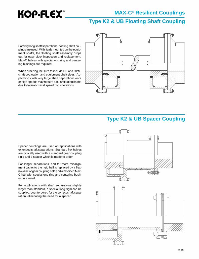
®
M-93
MAX-C® Resilient Couplings
Type K2 & UB Floating Shaft Coupling
Type K2 & UB Spacer Coupling
For very long shaft separations, floating shaft cou-plings are used. With rigids mounted on the equip-ment shafts, the floating shaft assembly dropsout for easy block inspection and replacement.Max-C halves with special end ring and center-ing bushings are required.
When ordering, be sure to include HP and RPM,shaft separation and equipment shaft sizes. Ap-plications with very large shaft separations and/or high speeds may require tubular floating shaftsdue to lateral critical speed considerations.
Spacer couplings are used on applications withextended shaft separations. Standard flex halvesare typically used with a standard gear couplingrigid and a spacer which is made to order.
For longer separations, and for more misalign-ment capacity, the rigid half is replaced by a flex-ible disc or gear coupling half, and a modified Max-C half with special end ring and centering bush-ing are used.
For applications with shaft separations slightlylarger than standard, a special long rigid can besupplied, counterbored for the correct shaft sepa-ration, eliminating the need for a spacer.
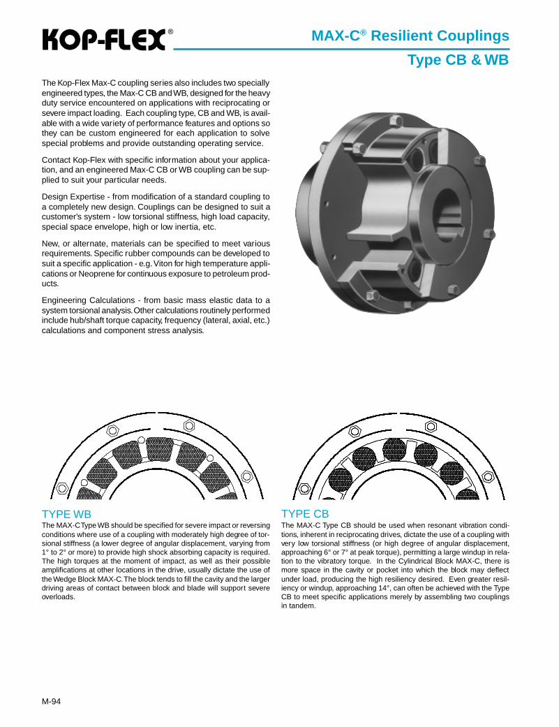
®
M-94
MAX-C® Resilient Couplings
Type CB & WB
The MAX-C Type WB should be specified for severe impact or reversingconditions where use of a coupling with moderately high degree of tor-sional stiffness (a lower degree of angular displacement, varying from1° to 2° or more) to provide high shock absorbing capacity is required.The high torques at the moment of impact, as well as their possibleamplifications at other locations in the drive, usually dictate the use ofthe Wedge Block MAX-C. The block tends to fill the cavity and the largerdriving areas of contact between block and blade will support severeoverloads.
The Kop-Flex Max-C coupling series also includes two speciallyengineered types, the Max-C CB and WB, designed for the heavyduty service encountered on applications with reciprocating orsevere impact loading. Each coupling type, CB and WB, is avail-able with a wide variety of performance features and options sothey can be custom engineered for each application to solvespecial problems and provide outstanding operating service.
Contact Kop-Flex with specific information about your applica-tion, and an engineered Max-C CB or WB coupling can be sup-plied to suit your particular needs.
Design Expertise - from modification of a standard coupling toa completely new design. Couplings can be designed to suit acustomer’s system - low torsional stiffness, high load capacity,special space envelope, high or low inertia, etc.
New, or alternate, materials can be specified to meet variousrequirements. Specific rubber compounds can be developed tosuit a specific application - e.g. Viton for high temperature appli-cations or Neoprene for continuous exposure to petroleum prod-ucts.
Engineering Calculations - from basic mass elastic data to asystem torsional analysis. Other calculations routinely performedinclude hub/shaft torque capacity, frequency (lateral, axial, etc.)calculations and component stress analysis.
The MAX-C Type CB should be used when resonant vibration condi-tions, inherent in reciprocating drives, dictate the use of a coupling withvery low torsional stiffness (or high degree of angular displacement,approaching 6° or 7° at peak torque), permitting a large windup in rela-tion to the vibratory torque. In the Cylindrical Block MAX-C, there ismore space in the cavity or pocket into which the block may deflectunder load, producing the high resiliency desired. Even greater resil-iency or windup, approaching 14°, can often be achieved with the TypeCB to meet specific applications merely by assembling two couplingsin tandem.
TYPE WB TYPE CB
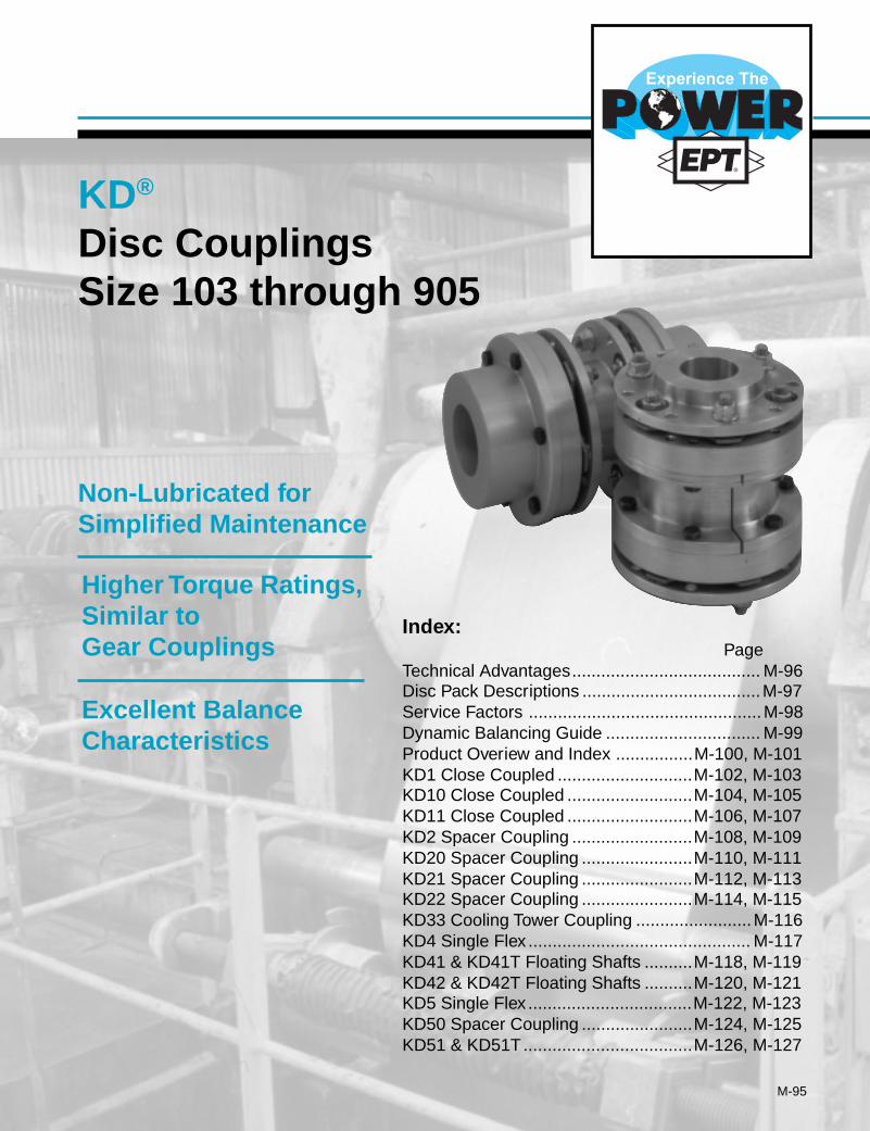
M-95
Higher Torque Ratings,Similar toGear Couplings
Excellent BalanceCharacteristics
Index:Page
Technical Advantages....................................... M-96Disc Pack Descriptions .....................................M-97Service Factors ................................................M-98Dynamic Balancing Guide ................................ M-99Product Overiew and Index ................M-100, M-101KD1 Close Coupled ............................M-102, M-103KD10 Close Coupled ..........................M-104, M-105KD11 Close Coupled ..........................M-106, M-107KD2 Spacer Coupling .........................M-108, M-109KD20 Spacer Coupling .......................M-110, M-111KD21 Spacer Coupling .......................M-112, M-113KD22 Spacer Coupling .......................M-114, M-115KD33 Cooling Tower Coupling ........................M-116KD4 Single Flex .............................................. M-117KD41 & KD41T Floating Shafts ..........M-118, M-119KD42 & KD42T Floating Shafts ..........M-120, M-121KD5 Single Flex ..................................M-122, M-123KD50 Spacer Coupling .......................M-124, M-125KD51 & KD51T...................................M-126, M-127
KD®
Disc CouplingsSize 103 through 905
Non-Lubricated forSimplified Maintenance
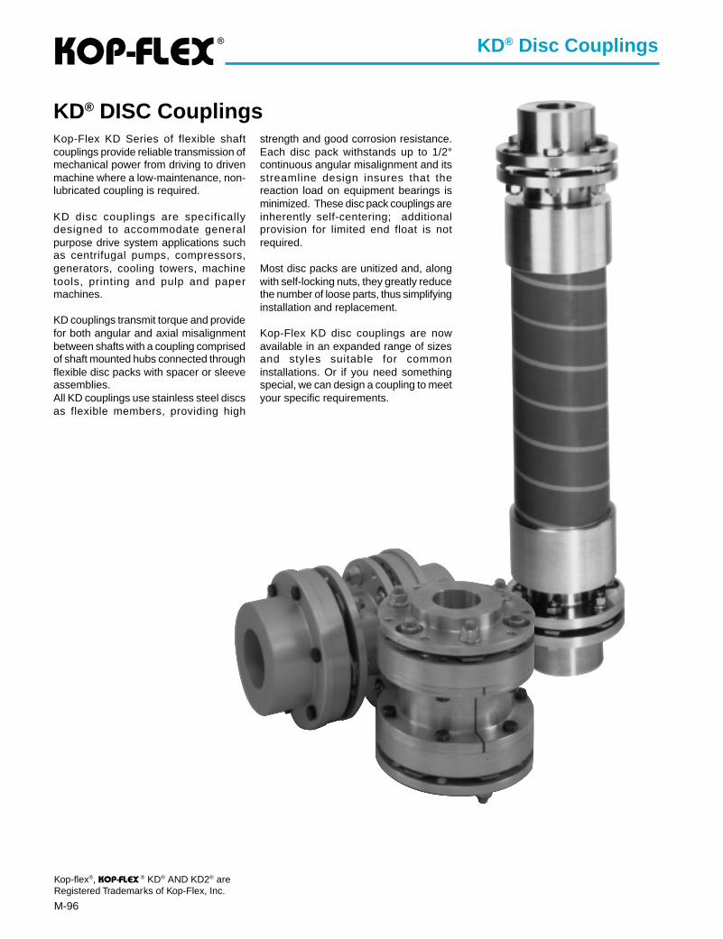
®
M-96
KD® DISC CouplingsKop-Flex KD Series of flexible shaftcouplings provide reliable transmission ofmechanical power from driving to drivenmachine where a low-maintenance, non-lubricated coupling is required.
KD disc couplings are specificallydesigned to accommodate generalpurpose drive system applications suchas centrifugal pumps, compressors,generators, cooling towers, machinetools, printing and pulp and papermachines.
KD couplings transmit torque and providefor both angular and axial misalignmentbetween shafts with a coupling comprisedof shaft mounted hubs connected throughflexible disc packs with spacer or sleeveassemblies.All KD couplings use stainless steel discsas flexible members, providing high
strength and good corrosion resistance.Each disc pack withstands up to 1/2°continuous angular misalignment and itsstreamline design insures that thereaction load on equipment bearings isminimized. These disc pack couplings areinherently self-centering; additionalprovision for limited end float is notrequired.
Most disc packs are unitized and, alongwith self-locking nuts, they greatly reducethe number of loose parts, thus simplifyinginstallation and replacement.
Kop-Flex KD disc couplings are nowavailable in an expanded range of sizesand styles suitable for commoninstallations. Or if you need somethingspecial, we can design a coupling to meetyour specific requirements.
Kop-flex®, ® KD® AND KD2® areRegistered Trademarks of Kop-Flex, Inc.
KD® Disc Couplings
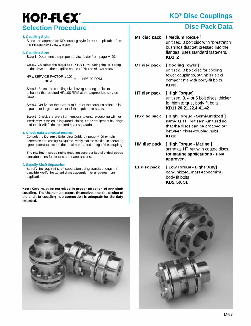
®
M-97
MT disc pack [ Medium Torque ]unitized, 3 bolt disc with “prestretch”bushings that get pressed into theflanges, uses standard fasteners.KD1, 2
CT disc pack [ Cooling Tower ]unitized, 3 bolt disc for coolingtower couplings, stainless steelcomponents with body-fit bolts.KD33
HT disc pack [ High Torque]unitized, 3, 4 or 5 bolt discs, thickerfor high torque, body fit bolts.KD11,20,21,22,4,41,42
HS disc pack [ High Torque - Semi-unitized ]same as HT but semi-unitized sothat the discs can be dropped outbetween close-coupled hubs.KD10
HM disc pack [ High Torque - Marine ]same as HT but with coated discs,for marine applications - DNVapproved.
LT disc pack [ Low Torque - Light Duty]non-unitized, most economical,body fit bolts.KD5, 50, 51
1. Coupling Style:Select the appropriate KD coupling style for your application fromthe Product Overview & Index.
2. Coupling Size:Step 1: Determine the proper service factor from page M-99.
Step 2: Calculate the required HP/100 RPM, using the HP ratingof the drive and the coupling speed (RPM) as shown below:
HP x SERVICE FACTOR x 100 = HP/100 RPM
RPM
Step 3: Select the coupling size having a rating sufficientto handle the required HP/100 RPM at the appropriate servicefactor.
Step 4: Verify that the maximum bore of the coupling selected isequal to or larger than either of the equipment shafts.
Step 5: Check the overall dimensions to ensure coupling will notinterfere with the coupling guard, piping, or the equipment housingsand that it will fit the required shaft separation.
3. Check Balance RequirementsConsult the Dynamic Balancing Guide on page M-99 to helpdetermine if balancing is required. Verify that the maximum operatingspeed does not exceed the maximum speed rating of the coupling.
The maximum speed rating does not consider lateral critical speedconsiderations for floating shaft applications.
4. Specify Shaft SeparationSpecify the required shaft separation using standard length, ifpossible. Verify the actual shaft seperation for a replacementapplication.
Note: Care must be exercised in proper selection of any shaftcoupling. The Users must assure themselves that the design ofthe shaft to coupling hub connection is adequate for the dutyintended.
KD® Disc Couplings
Disc Pack DataSelection Procedure
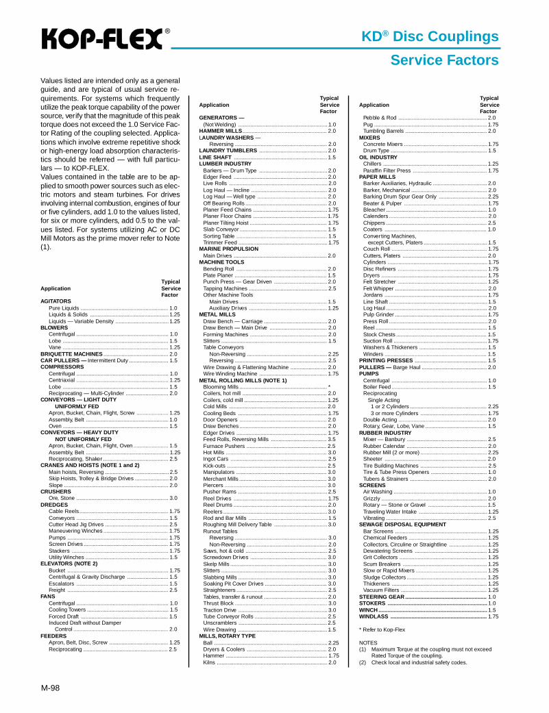
®
M-98
KD® Disc Couplings
Service Factors
TypicalApplication Ser vice
FactorAGITATORS
Pure Liquids .......................................................... 1.0Liquids & Solids .................................................... 1.25Liquids — Variable Density ................................... 1.25
BLOWERSCentrifugal ............................................................. 1.0Lobe ...................................................................... 1.5Vane ...................................................................... 1.25
BRIQUETTE MACHINES ........................................... 2.0CAR PULLERS — Intermittent Duty .......................... 1.5COMPRESSORS
Centrifugal ............................................................. 1.0Centriaxial ............................................................. 1.25Lobe ...................................................................... 1.5Reciprocating — Multi-Cylinder ............................ 2.0
CONVEYORS — LIGHT DUTY UNIFORMLY FEDApron, Bucket, Chain, Flight, Screw ..................... 1.25Assembly, Belt ....................................................... 1.0Oven ...................................................................... 1.5
CONVEYORS — HEAVY DUTY NOT UNIFORMLY FEDApron, Bucket, Chain, Flight, Oven ....................... 1.5Assembly, Belt ....................................................... 1.25Reciprocating, Shaker ........................................... 2.5
CRANES AND HOISTS (NOTE 1 and 2)Main hoists, Reversing .......................................... 2.5Skip Hoists, Trolley & Bridge Drives ...................... 2.0Slope ..................................................................... 2.0
CRUSHERSOre, Stone ............................................................. 3.0
DREDGESCable Reels........................................................... 1.75Conveyors ............................................................. 1.5Cutter Head Jig Drives .......................................... 2.5Maneuvering Winches ........................................... 1.75Pumps ................................................................... 1.75Screen Drives ........................................................ 1.75Stackers ................................................................ 1.75Utility Winches ....................................................... 1.5
ELEVATORS (NOTE 2)Bucket ................................................................... 1.75Centrifugal & Gravity Discharge ........................... 1.5Escalators ............................................................. 1.5Freight ................................................................... 2.5
FANSCentrifugal ............................................................. 1.0Cooling Towers ...................................................... 1.5Forced Draft .......................................................... 1.5Induced Draft without Damper Control ............................................................... 2.0
FEEDERSApron, Belt, Disc, Screw ....................................... 1.25Reciprocating ........................................................ 2.5
TypicalApplication Ser vice
FactorGENERATORS —
(Not Welding) ........................................................... 1.0HAMMER MILLS ........................................................ 2.0LAUNDRY WASHERS —
Reversing ............................................................. 2.0LAUNDRY TUMBLERS ............................................. 2.0LINE SHAFT .............................................................. 1.5LUMBER INDUSTRY
Barkers — Drum Type ............................................. 2.0Edger Feed .............................................................. 2.0Live Rolls ................................................................. 2.0Log Haul — Incline .................................................. 2.0Log Haul — Well type .............................................. 2.0Off Bearing Rolls ...................................................... 2.0Planer Feed Chains ................................................. 1.75Planer Floor Chains ................................................. 1.75Planer Tilting Hoist ................................................... 1.75Slab Conveyor .......................................................... 1.5Sorting Table ............................................................ 1.5Trimmer Feed ........................................................... 1.75
MARINE PROPULSIONMain Drives .............................................................. 2.0
MACHINE TOOLSBending Roll ............................................................ 2.0Plate Planer ............................................................. 1.5Punch Press — Gear Driven ................................... 2.0Tapping Machines .................................................... 2.5Other Machine Tools Main Drives .......................................................... 1.5 Auxiliary Drives .................................................... 1.25
METAL MILLSDraw Bench — Carriage .......................................... 2.0Draw Bench — Main Drive ...................................... 2.0Forming Machines ................................................... 2.0Slitters ...................................................................... 1.5Table Conveyors Non-Reversing ..................................................... 2.25 Reversing ............................................................. 2.5Wire Drawing & Flattening Machine ........................ 2.0Wire Winding Machine ............................................. 1.75
METAL ROLLING MILLS (NOTE 1)Blooming Mills .......................................................... *Coilers, hot mill ........................................................ 2.0Coilers, cold mill ....................................................... 1.25Cold Mills ................................................................. 2.0Cooling Beds ........................................................... 1.75Door Openers .......................................................... 2.0Draw Benches .......................................................... 2.0Edger Drives ............................................................ 1.75Feed Rolls, Reversing Mills ..................................... 3.5Furnace Pushers ..................................................... 2.5Hot Mills ................................................................... 3.0Ingot Cars ................................................................ 2.5Kick-outs .................................................................. 2.5Manipulators ............................................................ 3.0Merchant Mills .......................................................... 3.0Piercers .................................................................... 3.0Pusher Rams ........................................................... 2.5Reel Drives .............................................................. 1.75Reel Drums .............................................................. 2.0Reelers ..................................................................... 3.0Rod and Bar Mills .................................................... 1.5Roughing Mill Delivery Table ................................... 3.0Runout Tables Reversing ............................................................. 3.0 Non-Reversing ..................................................... 2.0Saws, hot & cold ...................................................... 2.5Screwdown Drives ................................................... 3.0Skelp Mills ................................................................ 3.0Slitters ...................................................................... 3.0Slabbing Mills ........................................................... 3.0Soaking Pit Cover Drives ......................................... 3.0Straighteners ............................................................ 2.5Tables, transfer & runout .......................................... 2.0Thrust Block ............................................................. 3.0Traction Drive ........................................................... 3.0Tube Conveyor Rolls ................................................ 2.5Unscramblers ........................................................... 2.5Wire Drawing ........................................................... 1.5
MILLS, ROTARY TYPEBall ........................................................................... 2.25Dryers & Coolers ..................................................... 2.0Hammer ................................................................... 1.75Kilns ......................................................................... 2.0
TypicalApplication Ser vice
FactorPebble & Rod ........................................................... 2.0Pug ........................................................................... 1.75Tumbling Barrels ...................................................... 2.0
MIXERSConcrete Mixers ....................................................... 1.75Drum Type ................................................................ 1.5
OIL INDUSTRYChillers ..................................................................... 1.25Paraffin Filter Press ................................................. 1.75
PAPER MILLSBarker Auxiliaries, Hydraulic .................................... 2.0Barker, Mechanical .................................................. 2.0Barking Drum Spur Gear Only ................................ 2.25Beater & Pulper ....................................................... 1.75Bleacher ................................................................... 1.0Calenders ................................................................. 2.0Chippers ................................................................... 2.5Coaters .................................................................... 1.0Converting Machines, except Cutters, Platers .......................................... 1.5Couch Roll ............................................................... 1.75Cutters, Platers ........................................................ 2.0Cylinders .................................................................. 1.75Disc Refiners ........................................................... 1.75Dryers ...................................................................... 1.75Felt Stretcher ........................................................... 1.25Felt Whipper ............................................................. 2.0Jordans .................................................................... 1.75Line Shaft ................................................................. 1.5Log Haul ................................................................... 2.0Pulp Grinder ............................................................. 1.75Press Roll ................................................................. 2.0Reel .......................................................................... 1.5Stock Chests ............................................................ 1.5Suction Roll .............................................................. 1.75Washers & Thickeners ............................................. 1.5Winders .................................................................... 1.5
PRINTING PRESSES ................................................ 1.5PULLERS — Barge Haul ........................................... 2.0PUMPS
Centrifugal ............................................................... 1.0Boiler Feed ............................................................... 1.5Reciprocating Single Acting 1 or 2 Cylinders ................................................... 2.25 3 or more Cylinders ............................................ 1.75Double Acting ........................................................... 2.0Rotary, Gear, Lobe, Vane ......................................... 1.5
RUBBER INDUSTRYMixer — Banbury ..................................................... 2.5Rubber Calendar ..................................................... 2.0Rubber Mill (2 or more) ............................................ 2.25Sheeter .................................................................... 2.0Tire Building Machines ............................................ 2.5Tire & Tube Press Openers ..................................... 1.0Tubers & Strainers ................................................... 2.0
SCREENSAir Washing .............................................................. 1.0Grizzly ...................................................................... 2.0Rotary — Stone or Gravel ....................................... 1.5Traveling Water Intake ............................................. 1.25Vibrating ................................................................... 2.5
SEWAGE DISPOSAL EQUIPMENTBar Screens ............................................................. 1.25Chemical Feeders .................................................... 1.25Collectors, Circuline or Straightline ......................... 1.25Dewatering Screens ................................................ 1.25Grit Collectors .......................................................... 1.25Scum Breakers ........................................................ 1.25Slow or Rapid Mixers ............................................... 1.25Sludge Collectors ..................................................... 1.25Thickeners ............................................................... 1.25Vacuum Filters ......................................................... 1.25
STEERING GEAR ...................................................... 1.0STOKERS .................................................................. 1.0WINCH ........................................................................ 1.5WINDLASS ................................................................ 1.75
* Refer to Kop-Flex
NOTES(1) Maximum Torque at the coupling must not exceed
Rated Torque of the coupling.(2) Check local and industrial safety codes.
Values listed are intended only as a generalguide, and are typical of usual service re-quirements. For systems which frequentlyutilize the peak torque capability of the powersource, verify that the magnitude of this peaktorque does not exceed the 1.0 Service Fac-tor Rating of the coupling selected. Applica-tions which involve extreme repetitive shockor high-energy load absorption characteris-tics should be referred — with full particu-lars — to KOP-FLEX.Values contained in the table are to be ap-plied to smooth power sources such as elec-tric motors and steam turbines. For drivesinvolving internal combustion, engines of fouror five cylinders, add 1.0 to the values listed,for six or more cylinders, add 0.5 to the val-ues listed. For systems utilizing AC or DCMill Motors as the prime mover refer to Note(1).
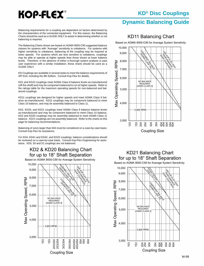
®
M-99
KD® Disc Couplings
Dynamic Balancing GuideBalancing requirements for a coupling are dependent on factors determined bythe characteristics of the connected equipment. For this reason, the BalancingCharts should be used as a GUIDE ONLY to assist in determining whether or notbalancing is required.
The Balancing Charts shown are based on AGMA 9000-C90 suggested balanceclasses for systems with “Average” sensitivity to unbalance. For systems withhigher sensitivity to unbalance, balancing of the coupling may be required atlower speeds. For systems which are less sensitive to unbalance, couplingsmay be able to operate at higher speeds than those shown at lower balancelevels. Therefore, in the absence of either a thorough system analysis or pastuser experience with a similar installation, these charts should be used as aGUIDE ONLY.
KD Couplings are available in several styles to meet the balance requirements ofAPI 610, including the 8th Edition. Consult Kop-Flex for details.
KD1 and KD10 couplings meet AGMA Class 8 balance levels as-manufactured(off-the-shelf) and may be component balanced to run at higher speeds. Refer tothe ratings table for the maximum operating speeds for non-balanced and bal-anced couplings.
KD11 couplings are designed for higher speeds and meet AGMA Class 9 bal-ance as-manufactured. KD11 couplings may be component balanced to meetClass 10 balance, and may be assembly balanced to Class 11.
KD2, KD20, and KD21 couplings meet AGMA Class 9 balance balance levelsas-manufactured and may be component balanced to meet Class 10 balance.KD2 and KD20 couplings may be assembly balanced to meet AGMA Class 11balance. KD21 couplings are not assembly balanced. Refer to the charts on thispage for balancing recommendations.
Balancing of sizes larger than 604 must be considered on a case-by-case basis.Consult Kop-Flex for assistance.
For KD4, KD41 and KD42, and KD22 couplings, balance considerations shouldbe reviewed on a case-by-case basis. Consult Kop-Flex Engineering for assis-tance. KD5, 50 and 51 couplings are not balanced.
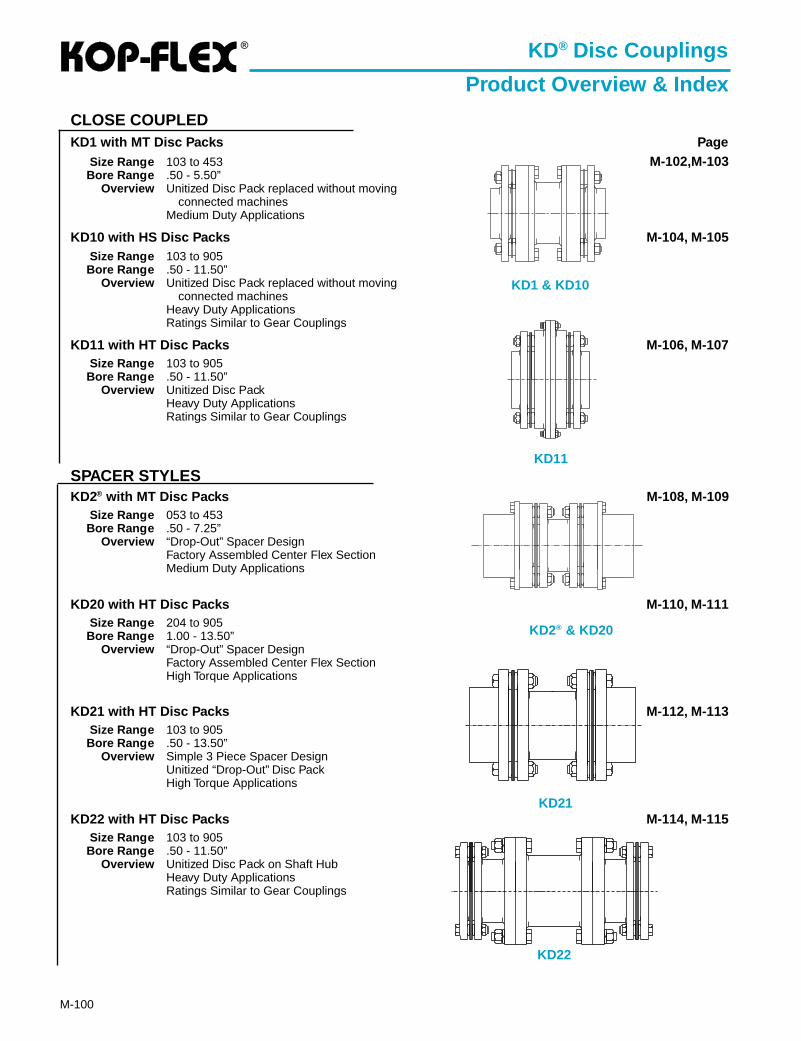
®
M-100
CLOSE COUPLEDKD1 with MT Disc Packs Page
Size Range 103 to 453 M-102,M-103Bore Range .50 - 5.50”
Overview Unitized Disc Pack replaced without movingconnected machines
Medium Duty Applications
KD10 with HS Disc Packs M-104, M-105Size Range 103 to 905Bore Range .50 - 11.50”
Overview Unitized Disc Pack replaced without movingconnected machines
Heavy Duty ApplicationsRatings Similar to Gear Couplings
KD11 with HT Disc Packs M-106, M-107Size Range 103 to 905Bore Range .50 - 11.50”
Overview Unitized Disc PackHeavy Duty ApplicationsRatings Similar to Gear Couplings
SPACER STYLESKD2® with MT Disc Packs M-108, M-109
Size Range 053 to 453Bore Range .50 - 7.25”
Overview “Drop-Out” Spacer DesignFactory Assembled Center Flex SectionMedium Duty Applications
KD20 with HT Disc Packs M-110, M-111Size Range 204 to 905Bore Range 1.00 - 13.50”
Overview “Drop-Out” Spacer DesignFactory Assembled Center Flex SectionHigh Torque Applications
KD21 with HT Disc Packs M-112, M-113Size Range 103 to 905Bore Range .50 - 13.50”
Overview Simple 3 Piece Spacer DesignUnitized “Drop-Out” Disc PackHigh Torque Applications
KD22 with HT Disc Packs M-114, M-115Size Range 103 to 905Bore Range .50 - 11.50”
Overview Unitized Disc Pack on Shaft HubHeavy Duty ApplicationsRatings Similar to Gear Couplings
KD® Disc Couplings
Product Overview & Index
KD1 & KD10
KD11
KD2® & KD20
KD21
KD22
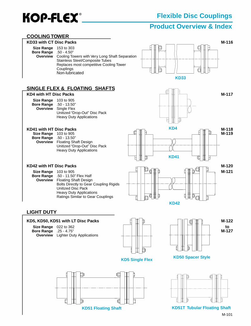
®
M-101
COOLING TOWERKD33 with CT Disc Packs M-116
Size Range 153 to 303Bore Range .50 - 4.50”
Overview Cooling Towers with Very Long Shaft SeparationStainless Steel/Composite TubesReplaces most competitive Cooling TowerCouplingsNon-lubricated
SINGLE FLEX & FLOATING SHAFTSKD4 with HT Disc Packs M-117
Size Range 103 to 905Bore Range .50 - 13.50”
Overview Single FlexUnitized “Drop-Out” Disc PackHeavy Duty Applications
KD41 with HT Disc Packs M-118Size Range 103 to 905 M-119Bore Range .50 - 13.50”
Overview Floating Shaft DesignUnitized “Drop-Out” Disc PackHeavy Duty Applications
KD42 with HT Disc Packs M-120Size Range 103 to 905 M-121Bore Range .50 - 11.50” Flex Half
Overview Floating Shaft DesignBolts Directly to Gear Coupling RigidsUnitized Disc PackHeavy Duty ApplicationsRatings Similar to Gear Couplings
LIGHT DUTY
KD5, KD50, KD51 with LT Disc Packs M-122Size Range 022 to 362 toBore Range .25 - 4.75” M-127
Overview Lighter Duty Applications
Flexible Disc Couplings
Product Overview & Index
KD33
KD4
KD51 Floating Shaft
KD5 Single FlexKD50 Spacer Style
KD42
KD41
KD51T Tubular Floating Shaft
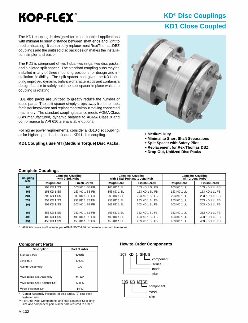
®
M-102
➀ All finish bores and keyways per AGMA 9002-A86 commercial standard tolerances.
Component Parts
KD® Disc Couplings
KD1 Close CoupledThe KD1 coupling is designed for close coupled applicationswith minimal to short distance between shaft ends and light tomedium loading. It can directly replace most Rex/Thomas DBZcouplings and the unitized disc pack design makes the installa-tion simpler and easier.
The KD1 is comprised of two hubs, two rings, two disc packs,and a piloted split spacer. The standard coupling hubs may beinstalled in any of three mounting positions for design and in-stallation flexibility. The split spacer pilot gives the KD1 cou-pling improved dynamic balance characteristics and contains adesign feature to safely hold the split spacer in place while thecoupling is rotating.
KD1 disc packs are unitized to greatly reduce the number ofloose parts. The split spacer simply drops away from the hubsfor faster installation and replacement without moving connectedmachinery. The standard coupling balance meets AGMA Class8 as manufactured, dynamic balance to AGMA Class 9 andconformance to API 610 are available options.
For higher power requirements, consider a KD10 disc coupling;or for higher speeds, check out a KD11 disc coupling.
KD1 Couplings use MT (Medium Torque) Disc Packs.
CouplingSize
Complete Couplingwith 2 Std. Hubs
Complete Couplingwith 1 Std. Hub and 1 Long Hub
Complete Couplingwith 2 Long Hubs
Rough Bore Finish Bore ➀ Rough Bore Finish Bore ➀ Rough Bore Finish Bore ➀
103 103 KD 1 SS 103 KD 1 SS FB 103 KD 1 SL 103 KD 1 SL FB 103 KD 1 LL 103 KD 1 LL FB
153 153 KD 1 SS 153 KD 1 SS FB 153 KD 1 SL 153 KD 1 SL FB 153 KD 1 LL 153 KD 1 LL FB
203 203 KD 1 SS 203 KD 1 SS FB 203 KD 1 SL 203 KD 1 SL FB 203 KD 1 LL 203 KD 1 LL FB
253 253 KD 1 SS 253 KD 1 SS FB 253 KD 1 SL 253 KD 1 SL FB 253 KD 1 LL 253 KD 1 LL FB
303 303 KD 1 SS 303 KD 1 SS FB 303 KD 1 SL 303 KD 1 SL FB 303 KD 1 LL 303 KD 1 LL FB
353 353 KD 1 SS 353 KD 1 SS FB 353 KD 1 SL 353 KD 1 SL FB 353 KD 1 LL 353 KD 1 LL FB
403 403 KD 1 SS 403 KD 1 SS FB 403 KD 1 SL 403 KD 1 SL FB 403 KD 1 LL 403 KD 1 LL FB
453 453 KD 1 SS 453 KD 1 SS FB 453 KD 1 SL 453 KD 1 SL FB 453 KD 1 LL 453 KD 1 LL FB
••••• Medium Duty••••• Minimal to Short Shaft Separations••••• Split Spacer with Safety Pilot••••• Replacement for Rex/Thomas DBZ••••• Drop-Out, Unitized Disc Packs
* Center Assembly includes (2) disc packs, (2) disc packfastener sets.
** For Disc Pack Components and Hub Fastener Sets, onlysize and component part number are required to order.
Complete Couplings
Description Part Number
Standard Hub SHUB
Long Hub LHUB
*Center Assembly CA
**MT Disc Pack Assembly MTDP
**MT Disc Pack Fastener Set MTFS
**Hub Fastener Set HFS
How to Order Components
103 KD 1 SHUB
size
model
component
103 KD MTDP
size
component
series
model
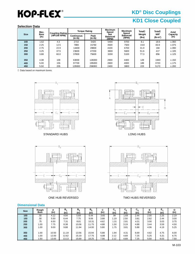
®
M-103
Dimensional Data
KD® Disc Couplings
KD1 Close CoupledSelection Data
LONG HUBSSTANDARD HUBS
ONE HUB REVERSED TWO HUBS REVERSED
① Data based on maximum bores.
SizeMax.Bore(in)
Coupling Rating(HP/100 RPM)
Torque Rating MaximumSpeed
NotBalanced
(RPM)
MaximumSpeed
Balanced(RPM)
Total①Weight
(lbs)
Total①WR2
(lb-in 2)
AxialCapacity
(in)Continuous(in-lb)
Peak(in-lb)
103 1.62 4.3 2710 5420 5400 9700 8.1 18.6 ±.060153 2.25 12.5 7880 15760 4500 7500 19.8 83.9 ±.075203 2.75 22.9 14400 28800 4100 6700 31.9 184 ±.090253 3.25 37.5 23600 47200 3600 5600 51.6 417 ±.105303 3.88 60.0 37800 75600 3200 5100 77.3 856 ±.125
353 4.38 100 63000 126000 2900 4400 129 1940 ±.150403 5.00 155 97700 195000 2600 4000 189 3720 ±.175453 5.50 205 129000 258000 2400 3800 223 5170 ±.200
Size RoughBore
A(in)
B1(in)
B2(in)
B3(in)
C(in)
C1(in)
C2(in)
C3(in)
E(in)
E1(in)
O(in)
103 .50 4.12 4.94 5.69 6.44 3.65 .94 1.69 2.44 2.00 2.25 2.19153 .50 5.50 6.44 7.75 9.06 3.88 1.19 2.50 3.81 2.62 2.44 3.00203 .75 6.50 7.31 8.81 10.31 4.62 1.31 2.81 4.31 3.00 3.03 3.75253 1.00 7.75 8.38 10.06 11.75 4.88 1.50 3.19 4.88 3.44 3.59 4.50303 1.00 9.00 9.88 11.94 14.00 5.80 1.75 3.81 5.88 4.06 4.19 5.25
353 1.00 10.50 11.19 13.56 15.94 5.88 1.94 4.31 6.69 4.62 4.75 6.00403 1.00 12.00 12.62 15.19 17.75 6.88 2.12 4.69 7.25 5.25 5.31 6.75453 1.50 13.00 13.13 15.69 18.25 7.56 2.12 4.69 7.25 5.50 6.03 7.50
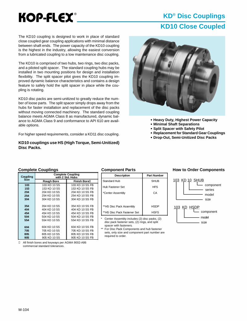
®
M-104
KD® Disc Couplings
KD10 Close CoupledThe KD10 coupling is designed to work in place of standardclose coupled gear coupling applications with minimal distancebetween shaft ends. The power capacity of the KD10 couplingis the highest in the industry, allowing the easiest conversionfrom a lubricated coupling to a low maintenance disc coupling.
The KD10 is comprised of two hubs, two rings, two disc packs,and a piloted split spacer. The standard coupling hubs may beinstalled in two mounting positions for design and installationflexibility. The split spacer pilot gives the KD10 coupling im-proved dynamic balance characteristics and contains a designfeature to safely hold the split spacer in place while the cou-pling is rotating.
KD10 disc packs are semi-unitized to greatly reduce the num-ber of loose parts. The split spacer simply drops away from thehubs for faster installation and replacement of the disc packswithout moving connected machinery. The standard couplingbalance meets AGMA Class 8 as manufactured, dynamic bal-ance to AGMA Class 9 and conformance to API 610 are avail-able options.
For higher speed requirements, consider a KD11 disc coupling.
KD10 couplings use HS (High Torque, Semi-Unitized)Disc Packs.
CouplingSize
Complete Couplingwith 2 Std. Hubs
Rough Bore Finish Bore ➀
103 103 KD 10 SS 103 KD 10 SS FB153 153 KD 10 SS 153 KD 10 SS FB204 204 KD 10 SS 204 KD 10 SS FB254 254 KD 10 SS 254 KD 10 SS FB304 304 KD 10 SS 304 KD 10 SS FB
354 354 KD 10 SS 354 KD 10 SS FB404 404 KD 10 SS 404 KD 10 SS FB454 454 KD 10 SS 454 KD 10 SS FB504 504 KD 10 SS 504 KD 10 SS FB554 554 KD 10 SS 554 KD 10 SS FB
604 604 KD 10 SS 604 KD 10 SS FB705 705 KD 10 SS 705 KD 10 SS FB805 805 KD 10 SS 805 KD 10 SS FB905 905 KD 10 SS 905 KD 10 SS FB
••••• Heavy Duty, Highest Power Capacity••••• Minimal Shaft Separations••••• Split Spacer with Safety Pilot••••• Replacement for Standard Gear Couplings••••• Drop-Out, Semi-Unitized Disc Packs
Complete Couplings Component Parts
* Center Assembly includes (2) disc packs, (2)disc pack fastener sets, (2) rings, and splitspacer with fasteners.
** For Disc Pack Components and hub fastenersets, only size and component part number arerequired to order.
➀ All finish bores and keyways per AGMA 9002-A86commercial standard tolerances.
Description Part Number
Standard Hub SHUB
Hub Fastener Set HFS
*Center Assembly CA
**HS Disc Pack Assembly HSDP
**HS Disc Pack Fastener Set HSFS
How to Order Components
103 KD 10 SHUB
sizemodel
componentseries
103 KD HSDP
size
component
model
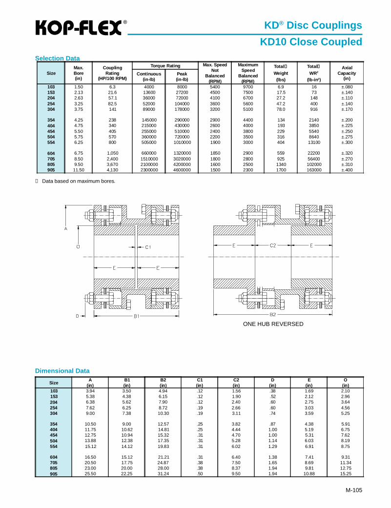
®
M-105
Dimensional Data
SizeA
(in)B1(in)
B2(in)
C1(in)
C2(in)
D(in)
E(in)
O(in)
103 3.94 3.50 4.94 .12 1.56 .38 1.69 2.10153 5.38 4.38 6.15 .12 1.90 .52 2.12 2.96204 6.38 5.62 7.90 .12 2.40 .60 2.75 3.64254 7.62 6.25 8.72 .19 2.66 .60 3.03 4.56304 9.00 7.38 10.30 .19 3.11 .74 3.59 5.25
354 10.50 9.00 12.57 .25 3.82 .87 4.38 5.91404 11.75 10.62 14.81 .25 4.44 1.00 5.19 6.75454 12.75 10.94 15.32 .31 4.70 1.00 5.31 7.62504 13.88 12.38 17.35 .31 5.28 1.14 6.03 8.19554 15.12 14.12 19.83 .31 6.02 1.29 6.91 8.75
604 16.50 15.12 21.21 .31 6.40 1.38 7.41 9.31705 20.50 17.75 24.87 .38 7.50 1.65 8.69 11.34805 23.00 20.00 28.00 .38 8.37 1.94 9.81 12.75905 25.50 22.25 31.24 .50 9.50 1.94 10.88 15.25
➀ Data based on maximum bores.
KD® Disc Couplings
KD10 Close CoupledSelection Data
ONE HUB REVERSED
SizeMax.Bore(in)
CouplingRating
(HP/100 RPM)
Torque Rating Max. SpeedNot
Balanced(RPM)
MaximumSpeed
Balanced(RPM)
Total ①
Weight(lbs)
Total①
WR2
(lb-in 2)
AxialCapacity
(in)Continuous
(in-lb)Peak(in-lb)
103 1.50 6.3 4000 8000 5400 9700 6.9 16 ±.080153 2.13 21.6 13600 27200 4500 7500 17.5 73 ±.140204 2.63 57.1 36000 72000 4100 6700 27.2 148 ±.110254 3.25 82.5 52000 104000 3600 5600 47.2 400 ±.140304 3.75 141 89000 178000 3200 5100 78.0 916 ±.170
354 4.25 238 145000 290000 2900 4400 134 2140 ±.200404 4.75 340 215000 430000 2600 4000 193 3850 ±.225454 5.50 405 255000 510000 2400 3800 229 5540 ±.250504 5.75 570 360000 720000 2200 3500 316 8640 ±.275554 6.25 800 505000 1010000 1900 3000 404 13100 ±.300
604 6.75 1,050 660000 1320000 1850 2900 559 22200 ±.320705 8.50 2,400 1510000 3020000 1800 2800 925 56400 ±.270805 9.50 3,670 2100000 4200000 1600 2500 1340 102000 ±.310905 11.50 4,130 2300000 4600000 1500 2300 1700 163000 ±.400
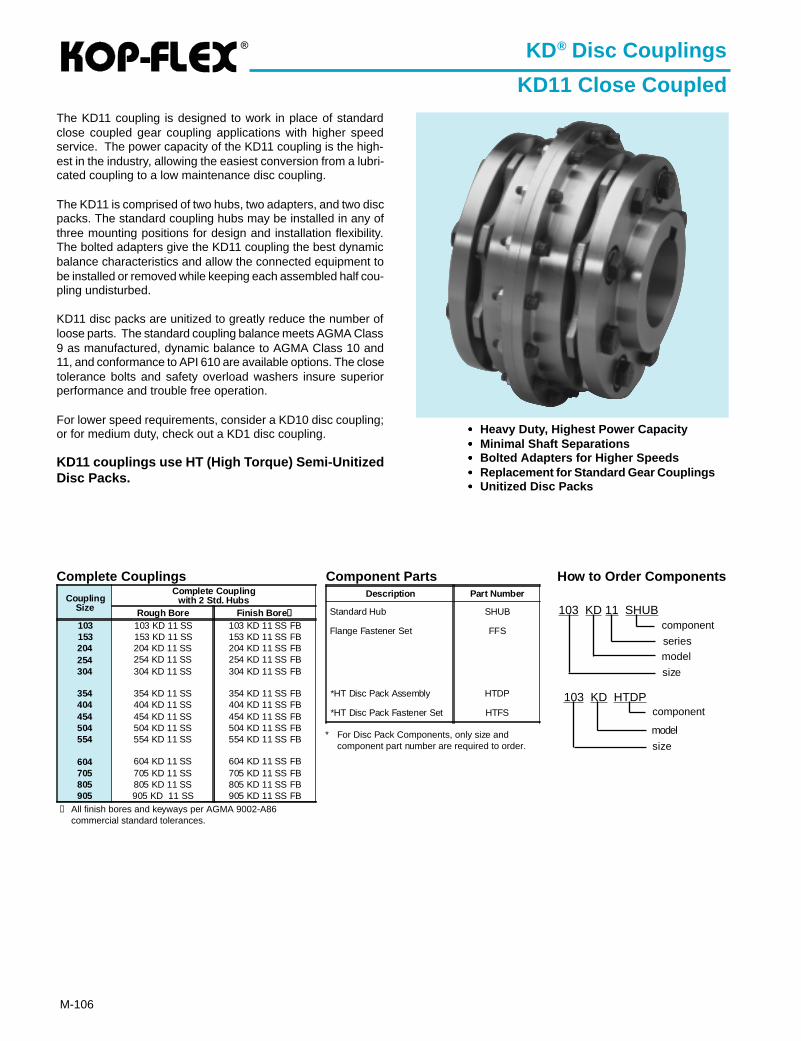
®
M-106
KD® Disc Couplings
KD11 Close CoupledThe KD11 coupling is designed to work in place of standardclose coupled gear coupling applications with higher speedservice. The power capacity of the KD11 coupling is the high-est in the industry, allowing the easiest conversion from a lubri-cated coupling to a low maintenance disc coupling.
The KD11 is comprised of two hubs, two adapters, and two discpacks. The standard coupling hubs may be installed in any ofthree mounting positions for design and installation flexibility.The bolted adapters give the KD11 coupling the best dynamicbalance characteristics and allow the connected equipment tobe installed or removed while keeping each assembled half cou-pling undisturbed.
KD11 disc packs are unitized to greatly reduce the number ofloose parts. The standard coupling balance meets AGMA Class9 as manufactured, dynamic balance to AGMA Class 10 and11, and conformance to API 610 are available options. The closetolerance bolts and safety overload washers insure superiorperformance and trouble free operation.
For lower speed requirements, consider a KD10 disc coupling;or for medium duty, check out a KD1 disc coupling.
KD11 couplings use HT (High Torque) Semi-UnitizedDisc Packs.
CouplingSize
Complete Couplingwith 2 Std. Hubs
Rough Bore Finish Bore ➀
103 103 KD 11 SS 103 KD 11 SS FB153 153 KD 11 SS 153 KD 11 SS FB204 204 KD 11 SS 204 KD 11 SS FB254 254 KD 11 SS 254 KD 11 SS FB304 304 KD 11 SS 304 KD 11 SS FB
354 354 KD 11 SS 354 KD 11 SS FB404 404 KD 11 SS 404 KD 11 SS FB454 454 KD 11 SS 454 KD 11 SS FB504 504 KD 11 SS 504 KD 11 SS FB554 554 KD 11 SS 554 KD 11 SS FB
604 604 KD 11 SS 604 KD 11 SS FB705 705 KD 11 SS 705 KD 11 SS FB805 805 KD 11 SS 805 KD 11 SS FB905 905 KD 11 SS 905 KD 11 SS FB
••••• Heavy Duty, Highest Power Capacity••••• Minimal Shaft Separations••••• Bolted Adapters for Higher Speeds••••• Replacement for Standard Gear Couplings••••• Unitized Disc Packs
Complete Couplings Component Parts
* For Disc Pack Components, only size andcomponent part number are required to order.
➀ All finish bores and keyways per AGMA 9002-A86commercial standard tolerances.
Description Part Number
Standard Hub SHUB
Flange Fastener Set FFS
*HT Disc Pack Assembly HTDP
*HT Disc Pack Fastener Set HTFS
How to Order Components
103 KD 11 SHUB
size
model
component
series
103 KD HTDP
size
component
model
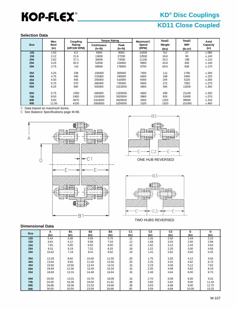
®
M-107
Dimensional Data
SizeA
(in)B1(in)
B2(in)
B3(in)
C1(in)
C2(in)
C3(in)
E(in)
O(in)
103 5.44 3.38 4.56 5.75 .12 1.31 2.50 1.64 2.10153 6.81 4.12 5.58 7.03 .12 1.58 3.03 2.00 2.96204 7.81 5.00 6.50 8.00 .12 1.62 3.12 2.44 3.64254 9.31 6.19 7.22 8.25 .19 1.22 2.25 3.00 4.56304 10.62 7.19 8.41 9.62 .19 1.41 2.62 3.50 5.25
354 12.28 8.50 10.00 11.50 .25 1.75 3.25 4.12 5.91404 13.94 9.50 11.50 13.50 .25 2.25 4.25 4.62 6.75454 15.56 10.56 12.44 14.31 .31 2.19 4.06 5.12 7.62504 16.69 11.56 13.45 15.34 .31 2.20 4.09 5.62 8.19554 18.69 12.31 14.48 16.64 .31 2.48 4.64 6.00 8.75
604 20.00 13.31 15.70 18.09 .31 2.70 5.09 6.50 9.31705 24.00 16.38 19.00 21.62 .38 3.00 5.62 8.00 11.34805 26.88 18.38 21.53 24.68 .38 3.53 6.68 9.00 12.75905 30.00 20.50 23.59 26.68 .50 3.59 6.68 10.00 15.25
① Data based on maximum bores.② See Balance Specifications page M-98.
KD® Disc Couplings
KD11 Close CoupledSelection Data
SizeMax.Bore(in)
CouplingRating
(HP/100 RPM)
Torque Rating Maximum ②Speed(RPM)
Total①Weight
(lbs)
Total①WR2
(lb-in 2)
AxialCapacity
(in)Continuous
(in-lb)Peak
(in-lb)
103 1.50 6.3 4000 8000 14200 9.0 27 ±.080153 2.12 21.6 13600 27200 12500 18.6 90 ±.140204 2.62 57.1 36000 72000 11100 29.2 189 ±.110254 3.25 82.5 52000 104000 9900 43.8 400 ±.140304 3.75 141 89000 178000 8700 69.6 839 ±.170
354 4.25 238 150000 300000 7500 111 1790 ±.200404 4.75 340 215000 430000 6600 168 3450 ±.225454 5.50 405 255000 510000 6000 204 5220 ±.250504 5.75 570 360000 720000 5600 272 7920 ±.275554 6.25 800 505000 1010000 4800 364 13200 ±.300
604 6.75 1050 660000 1320000 4600 458 21100 ±.320705 8.50 2400 1510000 3020000 3860 824 52400 ±.270805 9.50 3670 2310000 4620000 3450 1220 98000 ±.310905 11.50 4130 2600000 5200000 1520 1520 151000 ±.400
ONE HUB REVERSED
TWO HUBS REVERSED
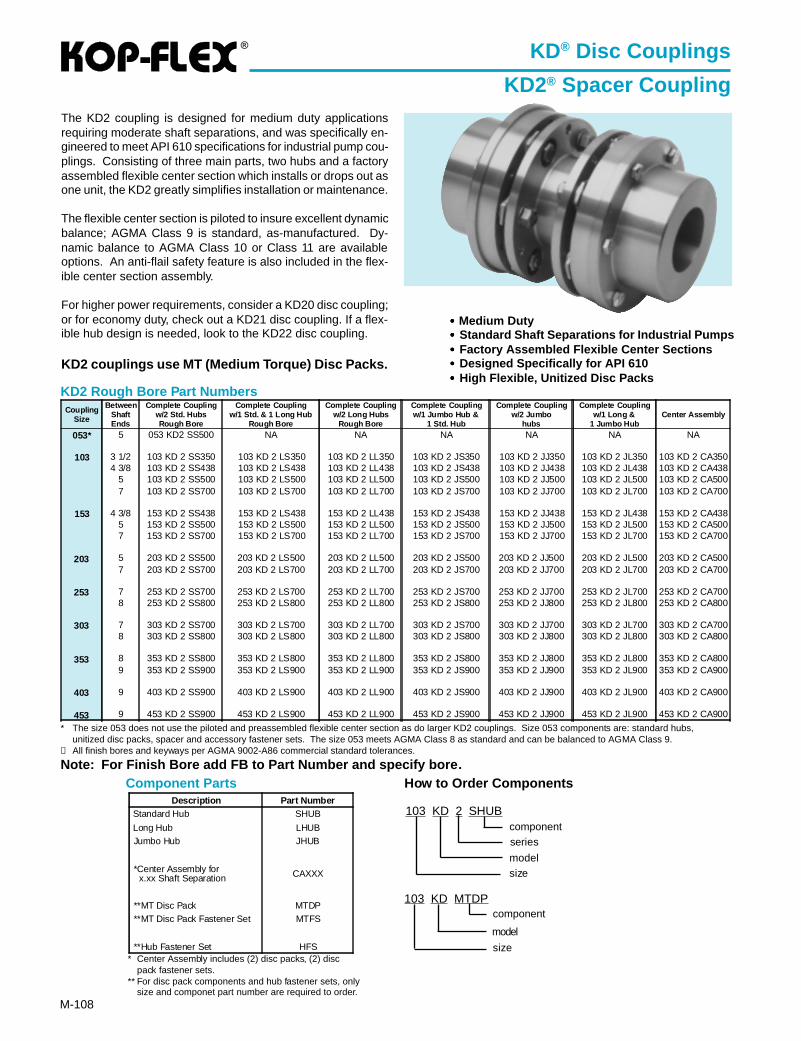
®
M-108
KD2 Rough Bore Part Numbers
Note: For Finish Bore add FB to Part Number and specify bore.Component Parts
KD® Disc Couplings
KD2® Spacer CouplingThe KD2 coupling is designed for medium duty applicationsrequiring moderate shaft separations, and was specifically en-gineered to meet API 610 specifications for industrial pump cou-plings. Consisting of three main parts, two hubs and a factoryassembled flexible center section which installs or drops out asone unit, the KD2 greatly simplifies installation or maintenance.
The flexible center section is piloted to insure excellent dynamicbalance; AGMA Class 9 is standard, as-manufactured. Dy-namic balance to AGMA Class 10 or Class 11 are availableoptions. An anti-flail safety feature is also included in the flex-ible center section assembly.
For higher power requirements, consider a KD20 disc coupling;or for economy duty, check out a KD21 disc coupling. If a flex-ible hub design is needed, look to the KD22 disc coupling.
KD2 couplings use MT (Medium Torque) Disc Packs.
* The size 053 does not use the piloted and preassembled flexible center section as do larger KD2 couplings. Size 053 components are: standard hubs,unitized disc packs, spacer and accessory fastener sets. The size 053 meets AGMA Class 8 as standard and can be balanced to AGMA Class 9.
➀ All finish bores and keyways per AGMA 9002-A86 commercial standard tolerances.
••••• Medium Duty••••• Standard Shaft Separations for Industrial Pumps••••• Factory Assembled Flexible Center Sections••••• Designed Specifically for API 610••••• High Flexible, Unitized Disc Packs
* Center Assembly includes (2) disc packs, (2) discpack fastener sets.
** For disc pack components and hub fastener sets, onlysize and componet part number are required to order.
Description Part NumberStandard Hub SHUB
Long Hub LHUBJumbo Hub JHUB
*Center Assembly for x.xx Shaft Separation CAXXX
**MT Disc Pack MTDP**MT Disc Pack Fastener Set MTFS
**Hub Fastener Set HFS
How to Order Components
103 KD 2 SHUB
sizemodel
componentseries
103 KD MTDP
size
component
model
CouplingSize
BetweenShaftEnds
Complete Couplingw/2 Std. HubsRough Bore
Complete Couplingw/1 Std. & 1 Long Hub
Rough Bore
Complete Couplingw/2 Long Hubs
Rough Bore
Complete Couplingw/1 Jumbo Hub &
1 Std. Hub
Complete Couplingw/2 Jumbo
hubs
Complete Couplingw/1 Long &
1 Jumbo HubCenter Assembly
053* 5 053 KD2 SS500 NA NA NA NA NA NA
103 3 1/2 103 KD 2 SS350 103 KD 2 LS350 103 KD 2 LL350 103 KD 2 JS350 103 KD 2 JJ350 103 KD 2 JL350 103 KD 2 CA3504 3/8 103 KD 2 SS438 103 KD 2 LS438 103 KD 2 LL438 103 KD 2 JS438 103 KD 2 JJ438 103 KD 2 JL438 103 KD 2 CA438
5 103 KD 2 SS500 103 KD 2 LS500 103 KD 2 LL500 103 KD 2 JS500 103 KD 2 JJ500 103 KD 2 JL500 103 KD 2 CA5007 103 KD 2 SS700 103 KD 2 LS700 103 KD 2 LL700 103 KD 2 JS700 103 KD 2 JJ700 103 KD 2 JL700 103 KD 2 CA700
153 4 3/8 153 KD 2 SS438 153 KD 2 LS438 153 KD 2 LL438 153 KD 2 JS438 153 KD 2 JJ438 153 KD 2 JL438 153 KD 2 CA4385 153 KD 2 SS500 153 KD 2 LS500 153 KD 2 LL500 153 KD 2 JS500 153 KD 2 JJ500 153 KD 2 JL500 153 KD 2 CA5007 153 KD 2 SS700 153 KD 2 LS700 153 KD 2 LL700 153 KD 2 JS700 153 KD 2 JJ700 153 KD 2 JL700 153 KD 2 CA700
203 5 203 KD 2 SS500 203 KD 2 LS500 203 KD 2 LL500 203 KD 2 JS500 203 KD 2 JJ500 203 KD 2 JL500 203 KD 2 CA5007 203 KD 2 SS700 203 KD 2 LS700 203 KD 2 LL700 203 KD 2 JS700 203 KD 2 JJ700 203 KD 2 JL700 203 KD 2 CA700
253 7 253 KD 2 SS700 253 KD 2 LS700 253 KD 2 LL700 253 KD 2 JS700 253 KD 2 JJ700 253 KD 2 JL700 253 KD 2 CA7008 253 KD 2 SS800 253 KD 2 LS800 253 KD 2 LL800 253 KD 2 JS800 253 KD 2 JJ800 253 KD 2 JL800 253 KD 2 CA800
303 7 303 KD 2 SS700 303 KD 2 LS700 303 KD 2 LL700 303 KD 2 JS700 303 KD 2 JJ700 303 KD 2 JL700 303 KD 2 CA7008 303 KD 2 SS800 303 KD 2 LS800 303 KD 2 LL800 303 KD 2 JS800 303 KD 2 JJ800 303 KD 2 JL800 303 KD 2 CA800
353 8 353 KD 2 SS800 353 KD 2 LS800 353 KD 2 LL800 353 KD 2 JS800 353 KD 2 JJ800 353 KD 2 JL800 353 KD 2 CA8009 353 KD 2 SS900 353 KD 2 LS900 353 KD 2 LL900 353 KD 2 JS900 353 KD 2 JJ900 353 KD 2 JL900 353 KD 2 CA900
403 9 403 KD 2 SS900 403 KD 2 LS900 403 KD 2 LL900 403 KD 2 JS900 403 KD 2 JJ900 403 KD 2 JL900 403 KD 2 CA900
453 9 453 KD 2 SS900 453 KD 2 LS900 453 KD 2 LL900 453 KD 2 JS900 453 KD 2 JJ900 453 KD 2 JL900 453 KD 2 CA900
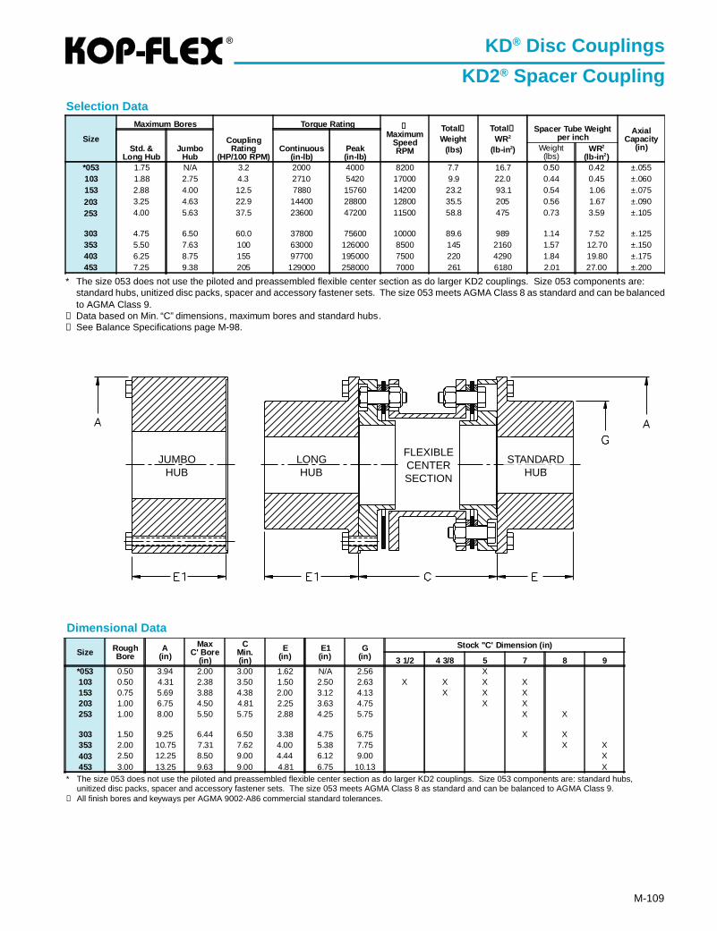
®
M-109
Dimensional Data
KD® Disc Couplings
KD2® Spacer CouplingSelection Data
* The size 053 does not use the piloted and preassembled flexible center section as do larger KD2 couplings. Size 053 components are:standard hubs, unitized disc packs, spacer and accessory fastener sets. The size 053 meets AGMA Class 8 as standard and can be balancedto AGMA Class 9.
➀ Data based on Min. “C” dimensions, maximum bores and standard hubs.➁ See Balance Specifications page M-98.
Size
Maximum Bores
CouplingRating
(HP/100 RPM)
Torque Rating ➁Maximum
SpeedRPM
Total①Weight
(lbs)
Total ➀WR2
(lb-in 2)
Spacer Tube Weightper inch
AxialCapacity
(in)Std. &Long Hub
JumboHub
Continuous(in-lb)
Peak(in-lb)
Weight(lbs)
WR2
(lb-in 2)*053 1.75 N/A 3.2 2000 4000 8200 7.7 16.7 0.50 0.42 ±.055103 1.88 2.75 4.3 2710 5420 17000 9.9 22.0 0.44 0.45 ±.060153 2.88 4.00 12.5 7880 15760 14200 23.2 93.1 0.54 1.06 ±.075203 3.25 4.63 22.9 14400 28800 12800 35.5 205 0.56 1.67 ±.090253 4.00 5.63 37.5 23600 47200 11500 58.8 475 0.73 3.59 ±.105
303 4.75 6.50 60.0 37800 75600 10000 89.6 989 1.14 7.52 ±.125353 5.50 7.63 100 63000 126000 8500 145 2160 1.57 12.70 ±.150403 6.25 8.75 155 97700 195000 7500 220 4290 1.84 19.80 ±.175453 7.25 9.38 205 129000 258000 7000 261 6180 2.01 27.00 ±.200
* The size 053 does not use the piloted and preassembled flexible center section as do larger KD2 couplings. Size 053 components are: standard hubs,unitized disc packs, spacer and accessory fastener sets. The size 053 meets AGMA Class 8 as standard and can be balanced to AGMA Class 9.
➀ All finish bores and keyways per AGMA 9002-A86 commercial standard tolerances.
STANDARDHUB
FLEXIBLECENTERSECTION
LONGHUB
JUMBOHUB
Size RoughBore
A(in)
MaxC' Bore
(in)
CMin.(in)
E(in)
E1(in)
G(in)
Stock "C' Dimension (in)
3 1/2 4 3/8 5 7 8 9*053 0.50 3.94 2.00 3.00 1.62 N/A 2.56 X10³ 0.50 4.31 2.38 3.50 1.50 2.50 2.63 X X X X153 0.75 5.69 3.88 4.38 2.00 3.12 4.13 X X X203 1.00 6.75 4.50 4.81 2.25 3.63 4.75 X X253 1.00 8.00 5.50 5.75 2.88 4.25 5.75 X X
303 1.50 9.25 6.44 6.50 3.38 4.75 6.75 X X353 2.00 10.75 7.31 7.62 4.00 5.38 7.75 X X403 2.50 12.25 8.50 9.00 4.44 6.12 9.00 X453 3.00 13.25 9.63 9.00 4.81 6.75 10.13 X
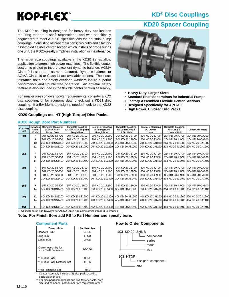
®
M-110
KD® Disc Couplings
KD20 Spacer CouplingThe KD20 coupling is designed for heavy duty applicationsrequiring moderate shaft separations, and was specificallyengineered to meet API 610 specifications for industrial pumpcouplings. Consisting of three main parts; two hubs and a factoryassembled flexible center section which installs or drops out asone unit, the KD20 greatly simplifies installation or maintenance.
The larger size couplings available in the KD20 Series allowapplication to larger, high power machines. The flexible centersection is piloted to insure excellent dynamic balance; AGMAClass 9 is standard, as-manufactured. Dynamic balance toAGMA Class 10 or Class 11 are available options. The closetolerance bolts and safety overload washers insure superiorperformance and trouble free operation. An anti-flail safetyfeature is also included in the flexible center section assembly.
For smaller sizes or lower power requirements, consider a KD2disc coupling; or for economy duty, check out a KD21 disccoupling. If a flexible hub design is needed, look to the KD22disc coupling.
KD20 Couplings use HT (High Torque) Disc Packs.
••••• Heavy Duty, Larger Sizes••••• Standard Shaft Separations for Industrial Pumps••••• Factory Assembled Flexible Center Sections••••• Designed Specifically for API 610••••• High Power, Unitized Disc Packs
KD20 Rough Bore Part Numbers
Note: For Finish Bore add FB to Part Number and specify bore.
Component Parts
➀ All finish bores and keyways per AGMA 9002-A86 commercial standard tolerances.
How to Order Components
103 KD 20 SHUB
size
model
component
103 HTDP
size
disc pack component
series
Description Part NumberStandard Hub SHUB
Long Hub LHUBJumbo Hub JHUB
*Center Assembly for x.xx Shaft Separation CAXXX
**HT Disc Pack HTDP
**HT Disc Pack Fastener Set HTFS
**Hub Fastener Set HFS
CouplingSize
BetweenShaftEnds
Complete Couplingw/2 Std. HubsRough Bore
Complete Couplingw/1 Std. & 1 Long Hub
Rough Bore
Complete Couplingw/2 Long Hubs
Rough Bore
Complete Couplingw/1 Jumbo Hub &
1 Std. Hub
Complete Couplingw/2 Jumbo
hubs
Complete Couplingw/1 Long &
1 Jumbo HubCenter Assembly
204 7 204 KD 20 SS700 204 KD 20 LS700 204 KD 20 LL700 204 KD 20 JS700 204 KD 20 JJ700 204 KD 20 JL700 204 KD 20 CA7009 204 KD 20 SS900 204 KD 20 LS900 204 KD 20 LL900 204 KD 20 JS900 204 KD 20 JJ900 204 KD 20 JL900 204 KD 20 CA900
10 204 KD 20 SS1000 204 KD 20 LS1000 204 KD 20 LL1000 204 KD 20 JS1000 204 KD 20 JJ1000 204 KD 20 JL1000 204 KD 20 CA100012 204 KD 20 SS1200 204 KD 20 LS1200 204 KD 20 LL1200 204 KD 20 JS1200 204 KD 20 JJ1200 204 KD 20 JL1200 204 KD 20 CA1200
254 7 254 KD 20 SS700 254 KD 20 LS700 254 KD 20 LL700 254 KD 20 JS700 254 KD 20 JJ700 254 KD 20 JL700 254 KD 20 CA7009 254 KD 20 SS900 254 KD 20 LS900 254 KD 20 LL900 254 KD 20 JS900 254 KD 20 JJ900 254 KD 20 JL900 254 KD 20 CA900
14 254 KD 20 SS1400 254 KD 20 LS1400 254 KD 20 LL1400 254 KD 20 JS1400 254 KD 20 JJ1400 254 KD 20 JL1400 254 KD 20 CA1400
304 7 304 KD 20 SS700 304 KD 20 LS700 304 KD 20 LL700 304 KD 20 JS700 304 KD 20 JJ700 304 KD 20 JL700 304 KD 20 CA7008 304 KD 20 SS800 304 KD 20 LS800 304 KD 20 LL800 304 KD 20 JS800 304 KD 20 JJ800 304 KD 20 JL800 304 KD 20 CA8009 304 KD 20 SS900 304 KD 20 LS900 304 KD 20 LL900 304 KD 20 JS900 304 KD 20 JJ900 304 KD 20 JL900 304 KD 20 CA900
14 304 KD 20 SS1400 304 KD 20 LS1400 304 KD 20 LL1400 304 KD 20 JS1400 304 KD 20 JJ1400 304 KD 20 JL1400 304 KD 20 CA1400
354 9 354 KD 20 SS900 354 KD 20 LS900 354 KD 20 LL900 354 KD 20 JS900 354 KD 20 JJ900 354 KD 20 JL900 354 KD 20 CA90014 354 KD 20 SS1400 354 KD 20 LS1400 354 KD 20 LL1400 354 KD 20 JS1400 354 KD 20 JJ1400 354 KD 20 JL1400 354 KD 20 CA1400
404 12 404 KD 20 SS1200 404 KD 20 LS1200 404 KD 20 LL1200 404 KD 20 JS1200 404 KD 20 JJ1200 404 KD 20 JL1200 404 KD 20 CA120014 404 KD 20 SS1400 404 KD 20 LS1400 404 KD 20 LL1400 404 KD 20 JS1400 404 KD 20 JJ1400 404 KD 20 JL1400 404 KD 20 CA1400
454 14 454 KD 20 SS1400 454 KD 20 LS1400 454 KD 20 LL1400 454 KD 20 JS1400 454 KD 20 JJ1400 454 KD 20 JL1400 454 KD 20 CA1400
* Center Assembly includes (2) disc packs, (2) discpack fastener sets.
** For disc pack components and hub fastener sets, onlysize and componet part number are required to order.
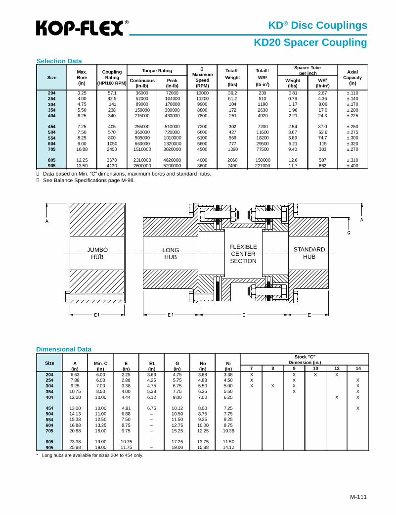
®
M-111
KD® Disc Couplings
KD20 Spacer Coupling
Selection Data
Dimensional Data
Size A(in)
Min. C(in)
E(in)
E1(in)
G(in)
No(in)
Ni(in)
Stock "C"Dimension (in.)
7 8 9 10 12 14204 6.63 6.00 2.25 3.63 4.75 3.88 3.38 X X X X254 7.88 6.00 2.88 4.25 5.75 4.88 4.50 X X X304 9.25 7.00 3.38 4.75 6.75 5.50 5.00 X X X X354 10.75 8.50 4.00 5.38 7.75 6.25 5.50 X X404 12.00 10.00 4.44 6.12 9.00 7.00 6.25 X X
454 13.00 10.00 4.81 6.75 10.12 8.00 7.25 X504 14.13 11.00 6.88 – 10.50 8.75 7.75554 15.38 12.50 7.50 – 11.50 9.25 8.25604 16.88 13.25 8.75 – 12.75 10.00 8.75705 20.88 16.00 9.75 – 15.25 12.25 10.38
805 23.38 19.00 10.75 – 17.25 13.75 11.50905 25.88 19.00 11.75 – 19.00 15.88 14.12
➀ Data based on Min. “C” dimensions, maximum bores and standard hubs.➁ See Balance Specifications page M-98.
SizeMax.Bore(in)
CouplingRating
(HP/100 RPM)
Torque Rating ➁
MaximumSpeed(RPM)
Total➀
Weight
(lbs)
Total➀
WR2
(lb-in 2)
Spacer Tubeper inch Axial
Capacity(in)Continuous
(in-lb)Peak(in-lb)
Weight(lbs)
WR2
(lb-in 2)
204 3.25 57.1 36000 72000 13000 39.2 230 0.81 2.67 ±.110254 4.00 82.5 52000 104000 11200 61.2 510 0.79 4.36 ±.140304 4.75 141 89000 178000 9900 104 1190 1.17 8.06 ±.170354 5.50 238 150000 300000 8800 172 2630 1.96 17.0 ±.200404 6.25 340 215000 430000 7800 251 4920 2.21 24.3 ±.225
454 7.25 405 255000 510000 7200 302 7200 2.54 37.0 ±.250504 7.50 570 360000 720000 6600 427 11600 3.67 62.6 ±.275554 8.25 800 505000 1010000 6100 569 18200 3.89 74.7 ±.300604 9.00 1050 660000 1320000 5600 777 29500 5.21 115 ±.320705 10.88 2400 1510000 3020000 4500 1360 77500 9.40 303 ±.270
805 12.25 3670 2310000 4620000 4000 2060 150000 12.6 507 ±.310905 13.50 4130 2600000 5200000 3600 2490 227000 11.7 662 ±.400
* Long hubs are available for sizes 204 to 454 only.
STANDARDHUB
LONGHUB
JUMBOHUB
FLEXIBLECENTERSECTION
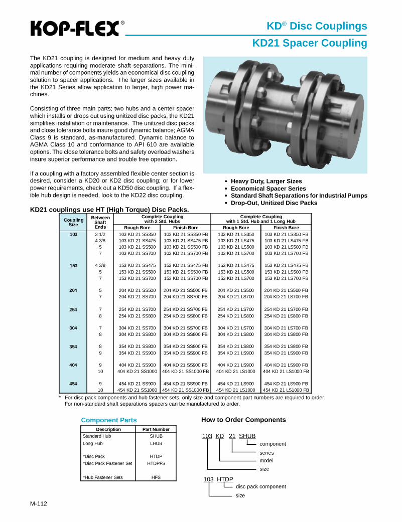
®
M-112
KD® Disc Couplings
KD21 Spacer CouplingThe KD21 coupling is designed for medium and heavy dutyapplications requiring moderate shaft separations. The mini-mal number of components yields an economical disc couplingsolution to spacer applications. The larger sizes available inthe KD21 Series allow application to larger, high power ma-chines.
Consisting of three main parts; two hubs and a center spacerwhich installs or drops out using unitized disc packs, the KD21simplifies installation or maintenance. The unitized disc packsand close tolerance bolts insure good dynamic balance; AGMAClass 9 is standard, as-manufactured. Dynamic balance toAGMA Class 10 and conformance to API 610 are availableoptions. The close tolerance bolts and safety overload washersinsure superior performance and trouble free operation.
If a coupling with a factory assembled flexible center section isdesired, consider a KD20 or KD2 disc coupling; or for lowerpower requirements, check out a KD50 disc coupling. If a flex-ible hub design is needed, look to the KD22 disc coupling.
KD21 couplings use HT (High Torque) Disc Packs.
Component Parts
••••• Heavy Duty, Larger Sizes••••• Economical Spacer Series••••• Standard Shaft Separations for Industrial Pumps••••• Drop-Out, Unitized Disc Packs
Description Part NumberStandard Hub SHUB
Long Hub LHUB
*Disc Pack HTDP
*Disc Pack Fastener Set HTDPFS
*Hub Fastener Sets HFS
How to Order Components
103 KD 21 SHUB
modelseries
component
size
103 HTDP
size
disc pack component
* For disc pack components and hub fastener sets, only size and component part numbers are required to order.For non-standard shaft separations spacers can be manufactured to order.
CouplingSize
BetweenShaftEnds
Complete Couplingwith 2 Std. Hubs
Complete Couplingwith 1 Std. Hub and 1 Long Hub
Rough Bore Finish Bore Rough Bore Finish Bore103 3 1/2 103 KD 21 SS350 103 KD 21 SS350 FB 103 KD 21 LS350 103 KD 21 LS350 FB
4 3/8 103 KD 21 SS475 103 KD 21 SS475 FB 103 KD 21 LS475 103 KD 21 LS475 FB5 103 KD 21 SS500 103 KD 21 SS500 FB 103 KD 21 LS500 103 KD 21 LS500 FB7 103 KD 21 SS700 103 KD 21 SS700 FB 103 KD 21 LS700 103 KD 21 LS700 FB
153 4 3/8 153 KD 21 SS475 153 KD 21 SS475 FB 153 KD 21 LS475 153 KD 21 LS475 FB5 153 KD 21 SS500 153 KD 21 SS500 FB 153 KD 21 LS500 153 KD 21 LS500 FB7 153 KD 21 SS700 153 KD 21 SS700 FB 153 KD 21 LS700 153 KD 21 LS700 FB
204 5 204 KD 21 SS500 204 KD 21 SS500 FB 204 KD 21 LS500 204 KD 21 LS500 FB7 204 KD 21 SS700 204 KD 21 SS700 FB 204 KD 21 LS700 204 KD 21 LS700 FB
254 7 254 KD 21 SS700 254 KD 21 SS700 FB 254 KD 21 LS700 254 KD 21 LS700 FB8 254 KD 21 SS800 254 KD 21 SS800 FB 254 KD 21 LS800 254 KD 21 LS800 FB
304 7 304 KD 21 SS700 304 KD 21 SS700 FB 304 KD 21 LS700 304 KD 21 LS700 FB8 304 KD 21 SS800 304 KD 21 SS800 FB 304 KD 21 LS800 304 KD 21 LS800 FB
354 8 354 KD 21 SS800 354 KD 21 SS800 FB 354 KD 21 LS800 354 KD 21 LS800 FB9 354 KD 21 SS900 354 KD 21 SS900 FB 354 KD 21 LS900 354 KD 21 LS900 FB
404 9 404 KD 21 SS900 404 KD 21 SS900 FB 404 KD 21 LS900 404 KD 21 LS900 FB10 404 KD 21 SS1000 404 KD 21 SS1000 FB 404 KD 21 LS1000 404 KD 21 LS1000 FB
454 9 454 KD 21 SS900 454 KD 21 SS900 FB 454 KD 21 LS900 454 KD 21 LS900 FB10 454 KD 21 SS1000 454 KD 21 SS1000 FB 454 KD 21 LS1000 454 KD 21 LS1000 FB
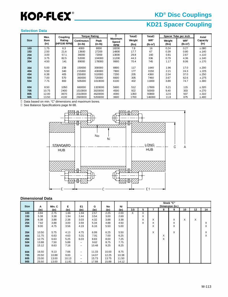
®
M-113
KD® Disc Couplings
KD21 Spacer CouplingSelection Data
SizeMax.Bore(in)
CouplingRating
(HP/100 RPM)
Torque Rating ➁
MaximumSpeedRPM
Total➀
Weight
(lbs)
Total➀
WR2
(lb-in 2)
Spacer Tube per inch AxialCapacity
(in)Continuous
(in-lb)Peak(in-lb)
Weight(lbs)
WR2
(lb-in 2)
103 1.75 6.3 4000 8000 18200 7.8 16 0.24 0.27 ±.080153 2.50 21.6 13600 27200 14800 17.7 67 0.39 0.80 ±.140204 3.00 57.1 36000 72000 13000 29.8 160 0.81 2.67 ±.110254 3.75 82.5 52000 104000 11200 44.3 336 0.79 4.36 ±.140304 4.50 141 89000 178000 9900 70.4 745 1.17 8.06 ±.170
354 5.00 238 150000 300000 8800 117 1640 1.96 17.0 ±.200404 5.50 340 215000 430000 7800 177 3150 2.21 24.3 ±.225454 6.38 405 255000 510000 7200 205 4360 2.54 37.0 ±.250504 7.00 570 360000 720000 6600 305 7460 3.67 62.6 ±.275554 7.75 800 505000 1010000 6100 402 11800 3.89 74.7 ±.300
604 8.50 1050 660000 1320000 5600 512 17800 5.21 115 ±.320705 10.75 2400 1510000 3020000 4500 922 50000 9.40 303 ±.270805 12.00 3670 2310000 4620000 4000 1350 93800 12.6 507 ±.310905 13.50 4130 2600000 5200000 3600 1700 146000 11.8 675 ±.400
Dimensional Data
➀ Data based on min. “C” dimensions and maximum bores.➁ See Balance Specifications page M-98.
Size A(in)
Min. C(in)
E(in)
E1(in)
G(in)
No(in)
Ni(in)
Stock "C"Dimension (in.)
3.5 5 7 8 9 10 12 14103 3.94 2.75 1.66 1.94 2.57 2.25 2.00 X X153 5.38 3.38 1.94 2.44 3.54 3.00 2.69 X204 6.38 3.88 2.38 3.03 4.32 3.88 3.38 X X X X X254 7.62 3.88 3.00 3.59 5.34 4.88 4.50 X X X X304 9.00 4.75 3.56 4.19 6.16 5.50 5.00 X X X
354 10.50 5.75 4.13 4.75 6.99 6.25 5.50 X X X404 11.75 6.63 4.63 5.31 7.91 7.00 6.25 X X454 12.75 6.63 5.25 6.03 8.83 8.00 7.25 X504 13.88 7.50 5.88 – 9.62 8.75 7.75554 15.12 8.63 7.16 – 10.48 9.25 8.25
604 16.50 9.13 7.66 – 11.33 10.00 8.75705 20.50 10.88 9.00 – 14.07 12.25 10.38805 23.00 13.00 10.13 – 15.73 13.75 11.50905 25.50 13.00 11.81 – 17.88 15.88 14.12
LONGHUB
STANDARDHUB
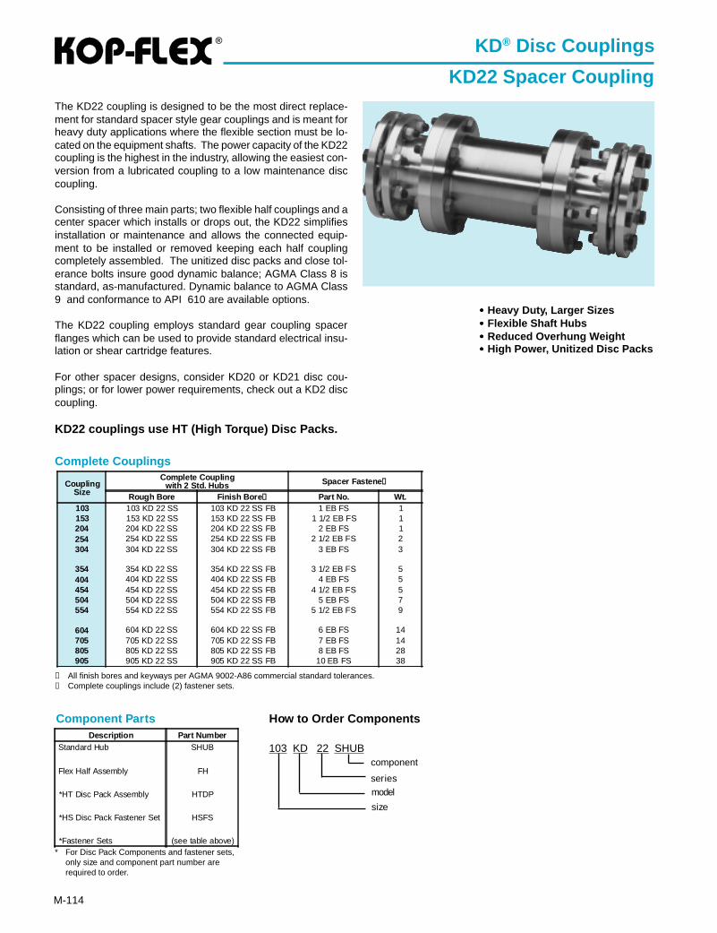
®
M-114
Complete Couplings
KD® Disc Couplings
KD22 Spacer CouplingThe KD22 coupling is designed to be the most direct replace-ment for standard spacer style gear couplings and is meant forheavy duty applications where the flexible section must be lo-cated on the equipment shafts. The power capacity of the KD22coupling is the highest in the industry, allowing the easiest con-version from a lubricated coupling to a low maintenance disccoupling.
Consisting of three main parts; two flexible half couplings and acenter spacer which installs or drops out, the KD22 simplifiesinstallation or maintenance and allows the connected equip-ment to be installed or removed keeping each half couplingcompletely assembled. The unitized disc packs and close tol-erance bolts insure good dynamic balance; AGMA Class 8 isstandard, as-manufactured. Dynamic balance to AGMA Class9 and conformance to API 610 are available options.
The KD22 coupling employs standard gear coupling spacerflanges which can be used to provide standard electrical insu-lation or shear cartridge features.
For other spacer designs, consider KD20 or KD21 disc cou-plings; or for lower power requirements, check out a KD2 disccoupling.
KD22 couplings use HT (High Torque) Disc Packs.
••••• Heavy Duty, Larger Sizes••••• Flexible Shaft Hubs••••• Reduced Overhung Weight••••• High Power, Unitized Disc Packs
Component Parts
* For Disc Pack Components and fastener sets,only size and component part number arerequired to order.
How to Order Components
103 KD 22 SHUB
modelseries
component
size
➀ All finish bores and keyways per AGMA 9002-A86 commercial standard tolerances.➁ Complete couplings include (2) fastener sets.
Description Part NumberStandard Hub SHUB
Flex Half Assembly FH
*HT Disc Pack Assembly HTDP
*HS Disc Pack Fastener Set HSFS
*Fastener Sets (see table above)
CouplingSize
Complete Couplingwith 2 Std. Hubs Spacer Fastene ➁
Rough Bore Finish Bore ➀ Part No. Wt.103 103 KD 22 SS 103 KD 22 SS FB 1 EB FS 1153 153 KD 22 SS 153 KD 22 SS FB 1 1/2 EB FS 1204 204 KD 22 SS 204 KD 22 SS FB 2 EB FS 1254 254 KD 22 SS 254 KD 22 SS FB 2 1/2 EB FS 2304 304 KD 22 SS 304 KD 22 SS FB 3 EB FS 3
354 354 KD 22 SS 354 KD 22 SS FB 3 1/2 EB FS 5404 404 KD 22 SS 404 KD 22 SS FB 4 EB FS 5454 454 KD 22 SS 454 KD 22 SS FB 4 1/2 EB FS 5504 504 KD 22 SS 504 KD 22 SS FB 5 EB FS 7554 554 KD 22 SS 554 KD 22 SS FB 5 1/2 EB FS 9
604 604 KD 22 SS 604 KD 22 SS FB 6 EB FS 14705 705 KD 22 SS 705 KD 22 SS FB 7 EB FS 14805 805 KD 22 SS 805 KD 22 SS FB 8 EB FS 28905 905 KD 22 SS 905 KD 22 SS FB 10 EB FS 38
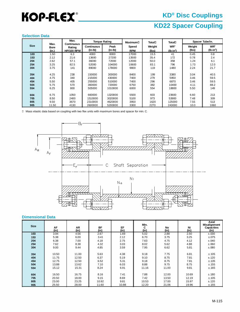
®
M-115
Dimensional Data
Size AF(in)
AR(in)
BF(in)
EF(in)
Min.C
(in)No(in)
Ni(in)
AxialMisalignment
Capacities(in)
103 3.94 4.56 2.67 1.69 5.02 2.88 2.50 ±.030153 5.38 6.00 3.41 2.12 6.70 3.75 3.25 ±.075204 6.38 7.00 4.18 2.75 7.63 4.75 4.12 ±.040254 7.62 8.38 4.32 3.03 8.02 5.62 4.88 ±.060304 9.00 9.44 4.85 3.59 7.95 6.62 5.81 ±.080
354 10.50 11.00 5.63 4.38 9.18 7.75 6.81 ±.105404 11.75 12.50 6.37 5.19 9.10 8.75 7.81 ±.120454 12.75 12.50 6.52 5.31 9.18 8.75 7.81 ±.135504 13.88 13.62 7.10 6.03 8.88 9.75 8.75 ±.155554 15.12 15.31 8.24 6.91 11.16 11.00 9.81 ±.165
604 16.50 16.75 8.16 7.41 7.88 12.00 10.69 ±.180705 20.50 18.00 9.15 8.69 7.42 13.50 12.19 ±.105805 23.00 23.25 10.92 9.81 10.53 17.00 15.97 ±.120905 25.50 28.00 11.60 10.88 12.20 21.06 19.96 ±.155
① Mass elastic data based on coupling with two flex units with maximum bores and spacer for min. C.
KD® Disc Couplings
KD22 Spacer Coupling
SizeMax.Bore(in.)
Max.Continuous
RatingHP/100 RPM
Torque Rating Maximum ②
Speed
RPM
Total ①
Weight
(lbs)
Total①
WR2
(lb-in 2)
Spacer Tube/in.
Continuous(in-lb)
Peak(in-lb)
Weight(lbs)
WR2
(lb-in 2)
103 1.50 6.3 4000 8000 17000 15.5 41 0.45 0.8153 2.12 21.6 13600 27200 13500 35.4 172 0.78 2.4204 2.62 57.1 36000 72000 12000 50.0 358 1.24 6.1254 3.25 82.5 52000 104000 10600 83.1 796 1.73 12.0304 3.75 141 89000 178000 9800 119 1480 2.24 21.7
354 4.25 238 150000 300000 8400 199 3380 3.04 40.5404 4.75 340 215000 430000 7400 279 5950 3.46 59.5454 5.50 405 255000 510000 7400 296 6870 3.46 59.5504 5.75 570 360000 720000 6750 382 10400 4.11 88.2554 6.25 800 505000 1010000 6000 554 18800 5.50 149
604 6.75 1050 660000 1320000 5500 603 23600 6.60 213705 8.50 2400 1510000 3020000 5100 973 53900 7.48 309805 9.50 3670 2310000 4620000 3950 1620 125000 7.55 513905 11.50 4130 2600000 5200000 3300 2270 243000 10.0 1060
Selection Data
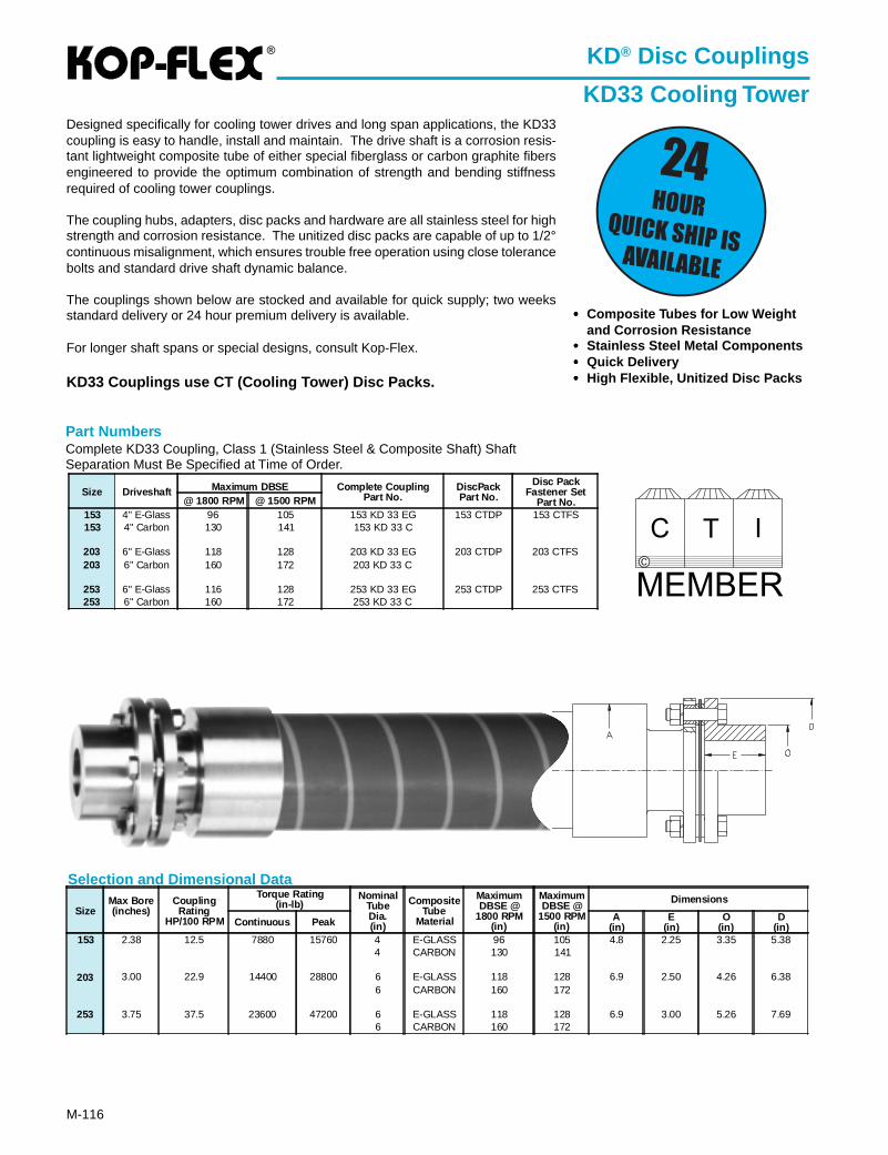
®
M-116
Selection and Dimensional Data
Part NumbersComplete KD33 Coupling, Class 1 (Stainless Steel & Composite Shaft) ShaftSeparation Must Be Specified at Time of Order.
Size Driveshaft Maximum DBSE Complete CouplingPart No.
DiscPackPart No.
Disc PackFastener Set
Part No.@ 1800 RPM @ 1500 RPM153 4" E-Glass 96 105 153 KD 33 EG 153 CTDP 153 CTFS153 4" Carbon 130 141 153 KD 33 C
203 6" E-Glass 118 128 203 KD 33 EG 203 CTDP 203 CTFS203 6" Carbon 160 172 203 KD 33 C
253 6" E-Glass 116 128 253 KD 33 EG 253 CTDP 253 CTFS253 6" Carbon 160 172 253 KD 33 C
KD® Disc Couplings
KD33 Cooling TowerDesigned specifically for cooling tower drives and long span applications, the KD33coupling is easy to handle, install and maintain. The drive shaft is a corrosion resis-tant lightweight composite tube of either special fiberglass or carbon graphite fibersengineered to provide the optimum combination of strength and bending stiffnessrequired of cooling tower couplings.
The coupling hubs, adapters, disc packs and hardware are all stainless steel for highstrength and corrosion resistance. The unitized disc packs are capable of up to 1/2°continuous misalignment, which ensures trouble free operation using close tolerancebolts and standard drive shaft dynamic balance.
The couplings shown below are stocked and available for quick supply; two weeksstandard delivery or 24 hour premium delivery is available.
For longer shaft spans or special designs, consult Kop-Flex.
KD33 Couplings use CT (Cooling Tower) Disc Packs.
••••• Composite Tubes for Low Weightand Corrosion Resistance
••••• Stainless Steel Metal Components••••• Quick Delivery••••• High Flexible, Unitized Disc Packs
SizeMax Bore(inches)
CouplingRating
HP/100 RPM
Torque Rating(in-lb)
NominalTubeDia.(in)
CompositeTube
Material
MaximumDBSE @
1800 RPM(in)
MaximumDBSE @
1500 RPM(in)
Dimensions
Continuous Peak A(in)
E(in)
O(in)
D(in)
153 2.38 12.5 7880 15760 4 E-GLASS 96 105 4.8 2.25 3.35 5.384 CARBON 130 141
203 3.00 22.9 14400 28800 6 E-GLASS 118 128 6.9 2.50 4.26 6.386 CARBON 160 172
253 3.75 37.5 23600 47200 6 E-GLASS 118 128 6.9 3.00 5.26 7.696 CARBON 160 172
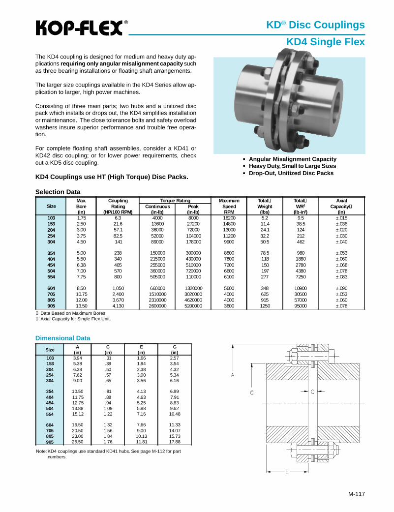
®
M-117
KD® Disc Couplings
KD4 Single FlexThe KD4 coupling is designed for medium and heavy duty ap-plications requiring only angular misalignment capacity suchas three bearing installations or floating shaft arrangements.
The larger size couplings available in the KD4 Series allow ap-plication to larger, high power machines.
Consisting of three main parts; two hubs and a unitized discpack which installs or drops out, the KD4 simplifies installationor maintenance. The close tolerance bolts and safety overloadwashers insure superior performance and trouble free opera-tion.
For complete floating shaft assemblies, consider a KD41 orKD42 disc coupling; or for lower power requirements, checkout a KD5 disc coupling.
KD4 Couplings use HT (High Torque) Disc Packs.
Dimensional Data
Selection Data
SizeMax.Bore(in)
CouplingRating
(HP/100 RPM)
Torque Rating MaximumSpeedRPM
Total ①Weight(lbs)
Total①WR2
(lb-in 2)
AxialCapacity ②
(in)Continuous
(in-lb)Peak(in-lb)
103 1.75 6.3 4000 8000 18200 5.2 9.5 ±.015153 2.50 21.6 13600 27200 14800 11.4 38.5 ±.038204 3.00 57.1 36000 72000 13000 24.1 124 ±.020254 3.75 82.5 52000 104000 11200 32.2 212 ±.030304 4.50 141 89000 178000 9900 50.5 462 ±.040
354 5.00 238 150000 300000 8800 78.5 980 ±.053404 5.50 340 215000 430000 7800 118 1880 ±.060454 6.38 405 255000 510000 7200 150 2780 ±.068504 7.00 570 360000 720000 6600 197 4380 ±.078554 7.75 800 505000 110000 6100 277 7250 ±.083
604 8.50 1,050 660000 1320000 5600 348 10900 ±.090705 10.75 2,400 1510000 3020000 4000 625 30500 ±.053805 12.00 3,670 2310000 4620000 4000 915 57000 ±.060905 13.50 4,130 2600000 5200000 3600 1250 95000 ±.078
① Data Based on Maximum Bores.② Axial Capacity for Single Flex Unit.
••••• Angular Misalignment Capacity••••• Heavy Duty, Small to Large Sizes••••• Drop-Out, Unitized Disc Packs
SizeA
(in)C
(in)E
(in)G
(in)103 3.94 .31 1.66 2.57153 5.38 .39 1.94 3.54204 6.38 .50 2.38 4.32254 7.62 .57 3.00 5.34304 9.00 .65 3.56 6.16
354 10.50 .81 4.13 6.99404 11.75 .88 4.63 7.91454 12.75 .94 5.25 8.83504 13.88 1.09 5.88 9.62554 15.12 1.22 7.16 10.48
604 16.50 1.32 7.66 11.33705 20.50 1.56 9.00 14.07805 23.00 1.84 10.13 15.73905 25.50 1.76 11.81 17.88
Note: KD4 couplings use standard KD41 hubs. See page M-112 for partnumbers.
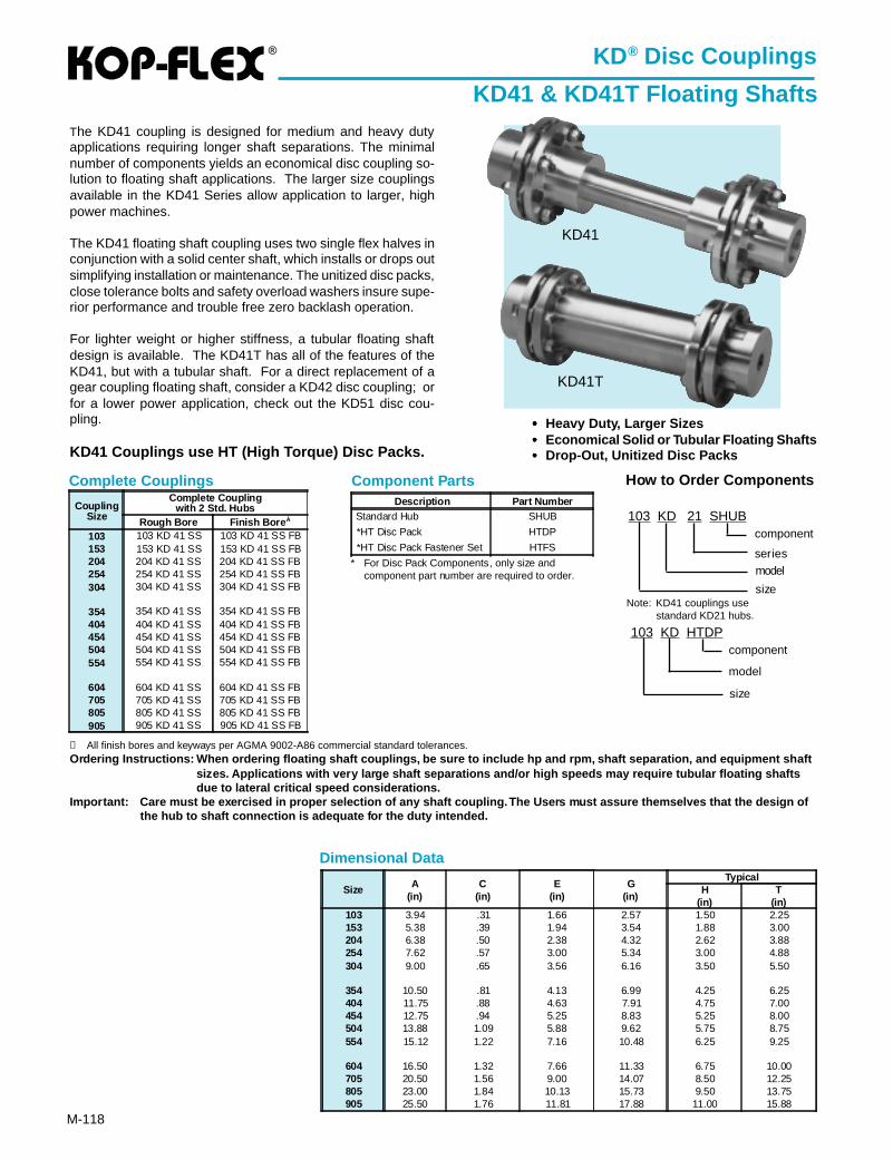
®
M-118
Component Parts
KD® Disc Couplings
KD41 & KD41T Floating ShaftsThe KD41 coupling is designed for medium and heavy dutyapplications requiring longer shaft separations. The minimalnumber of components yields an economical disc coupling so-lution to floating shaft applications. The larger size couplingsavailable in the KD41 Series allow application to larger, highpower machines.
The KD41 floating shaft coupling uses two single flex halves inconjunction with a solid center shaft, which installs or drops outsimplifying installation or maintenance. The unitized disc packs,close tolerance bolts and safety overload washers insure supe-rior performance and trouble free zero backlash operation.
For lighter weight or higher stiffness, a tubular floating shaftdesign is available. The KD41T has all of the features of theKD41, but with a tubular shaft. For a direct replacement of agear coupling floating shaft, consider a KD42 disc coupling; orfor a lower power application, check out the KD51 disc cou-pling.
KD41 Couplings use HT (High Torque) Disc Packs.
Dimensional Data
Size A(in)
C(in)
E(in)
G(in)
TypicalH
(in)T
(in)103 3.94 .31 1.66 2.57 1.50 2.25153 5.38 .39 1.94 3.54 1.88 3.00204 6.38 .50 2.38 4.32 2.62 3.88254 7.62 .57 3.00 5.34 3.00 4.88304 9.00 .65 3.56 6.16 3.50 5.50
354 10.50 .81 4.13 6.99 4.25 6.25404 11.75 .88 4.63 7.91 4.75 7.00454 12.75 .94 5.25 8.83 5.25 8.00504 13.88 1.09 5.88 9.62 5.75 8.75554 15.12 1.22 7.16 10.48 6.25 9.25
604 16.50 1.32 7.66 11.33 6.75 10.00705 20.50 1.56 9.00 14.07 8.50 12.25805 23.00 1.84 10.13 15.73 9.50 13.75905 25.50 1.76 11.81 17.88 11.00 15.88
KD41
KD41T
••••• Heavy Duty, Larger Sizes••••• Economical Solid or Tubular Floating Shafts••••• Drop-Out, Unitized Disc Packs
Description Part NumberStandard Hub SHUB
*HT Disc Pack HTDP
*HT Disc Pack Fastener Set HTFS
Complete Couplings
➀ All finish bores and keyways per AGMA 9002-A86 commercial standard tolerances.Ordering Instructions: When ordering floating shaft couplings, be sure to include hp and rpm, shaft separation, and equipment sh aft
sizes. Applications with very large shaft separations and/or high speeds may require tubular floating shaftsdue to lateral critical speed considerations.
Impor tant: Care must be exercised in proper selection of any shaft coupling. The Users must assure themselves that the design ofthe hub to shaft connection is adequate for the duty intended.
CouplingSize
Complete Couplingwith 2 Std. Hubs
Rough Bore Finish Bore À
103 103 KD 41 SS 103 KD 41 SS FB153 153 KD 41 SS 153 KD 41 SS FB204 204 KD 41 SS 204 KD 41 SS FB254 254 KD 41 SS 254 KD 41 SS FB304 304 KD 41 SS 304 KD 41 SS FB
354 354 KD 41 SS 354 KD 41 SS FB404 404 KD 41 SS 404 KD 41 SS FB454 454 KD 41 SS 454 KD 41 SS FB504 504 KD 41 SS 504 KD 41 SS FB554 554 KD 41 SS 554 KD 41 SS FB
604 604 KD 41 SS 604 KD 41 SS FB705 705 KD 41 SS 705 KD 41 SS FB805 805 KD 41 SS 805 KD 41 SS FB905 905 KD 41 SS 905 KD 41 SS FB
* For Disc Pack Components, only size andcomponent part number are required to order.
How to Order Components
103 KD 21 SHUB
modelseries
component
size
103 KD HTDP
size
component
model
Note: KD41 couplings usestandard KD21 hubs.
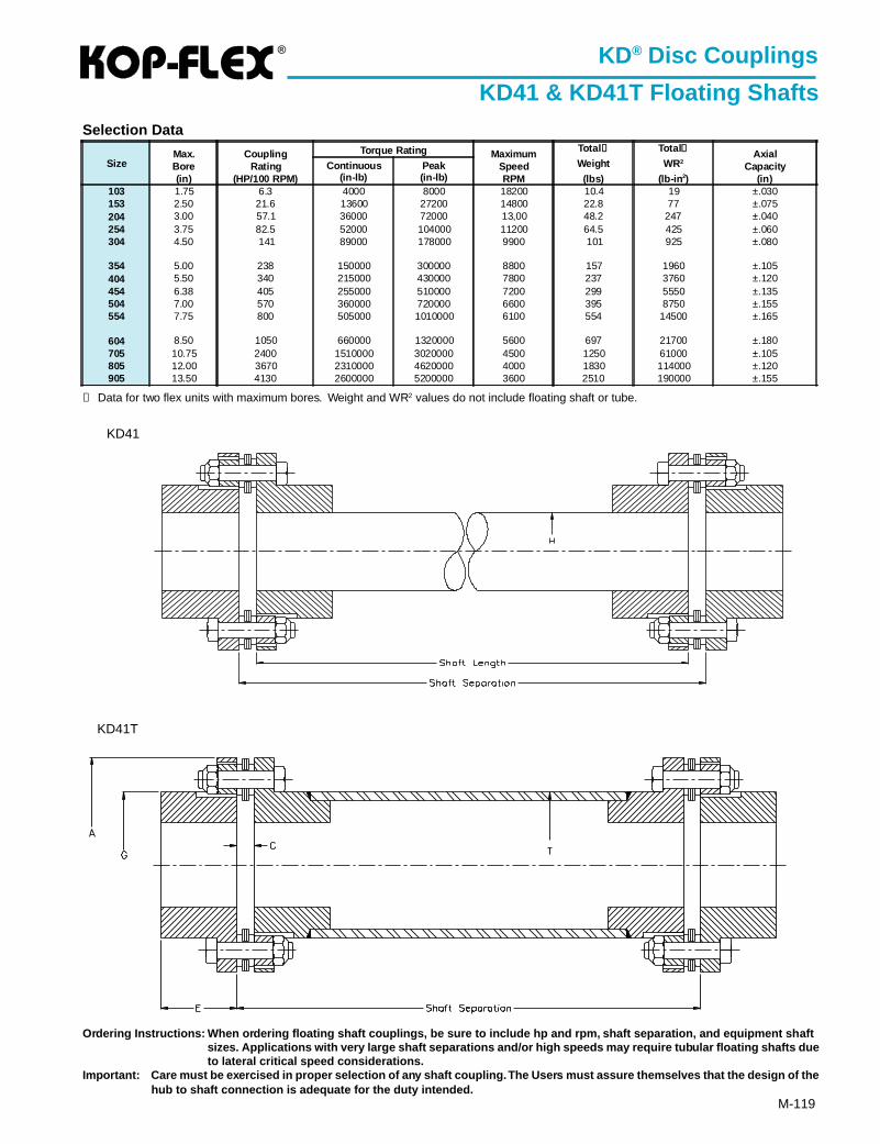
®
M-119
KD® Disc Couplings
KD41 & KD41T Floating ShaftsSelection Data
① Data for two flex units with maximum bores. Weight and WR2 values do not include floating shaft or tube.
KD41
KD41T
SizeMax.Bore(in)
CouplingRating
(HP/100 RPM)
Torque Rating MaximumSpeedRPM
Total ①
Weight
(lbs)
Total①
WR2
(lb-in 2)
AxialCapacity
(in)Continuous
(in-lb)Peak(in-lb)
103 1.75 6.3 4000 8000 18200 10.4 19 ±.030153 2.50 21.6 13600 27200 14800 22.8 77 ±.075204 3.00 57.1 36000 72000 13,00 48.2 247 ±.040254 3.75 82.5 52000 104000 11200 64.5 425 ±.060304 4.50 141 89000 178000 9900 101 925 ±.080
354 5.00 238 150000 300000 8800 157 1960 ±.105404 5.50 340 215000 430000 7800 237 3760 ±.120454 6.38 405 255000 510000 7200 299 5550 ±.135504 7.00 570 360000 720000 6600 395 8750 ±.155554 7.75 800 505000 1010000 6100 554 14500 ±.165
604 8.50 1050 660000 1320000 5600 697 21700 ±.180705 10.75 2400 1510000 3020000 4500 1250 61000 ±.105805 12.00 3670 2310000 4620000 4000 1830 114000 ±.120905 13.50 4130 2600000 5200000 3600 2510 190000 ±.155
Ordering Instructions: When ordering floating shaft couplings, be sure to include hp and rpm, shaft separation, and equipment sh aftsizes. Applications with very large shaft separations and/or high speeds may require tubular floating shafts dueto lateral critical speed considerations.
Impor tant: Care must be exercised in proper selection of any shaft coupling. The Users must assure themselves that the design of thehub to shaft connection is adequate for the duty intended.
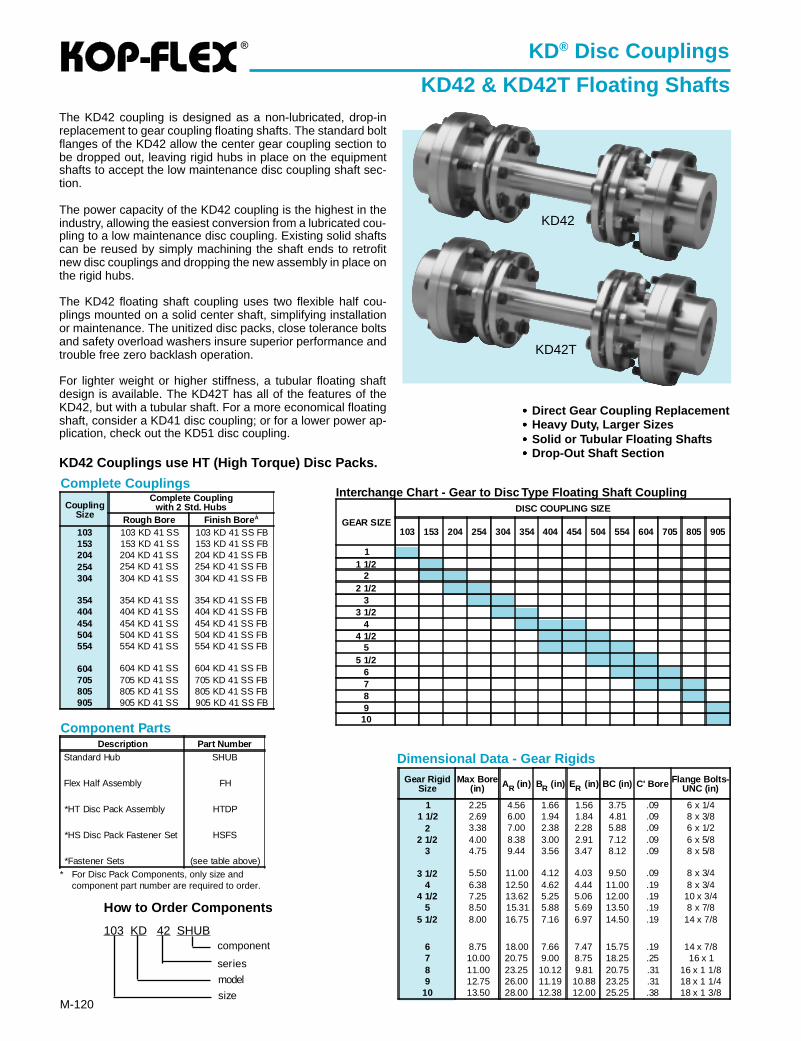
®
M-120
KD® Disc Couplings
KD42 & KD42T Floating ShaftsThe KD42 coupling is designed as a non-lubricated, drop-inreplacement to gear coupling floating shafts. The standard boltflanges of the KD42 allow the center gear coupling section tobe dropped out, leaving rigid hubs in place on the equipmentshafts to accept the low maintenance disc coupling shaft sec-tion.
The power capacity of the KD42 coupling is the highest in theindustry, allowing the easiest conversion from a lubricated cou-pling to a low maintenance disc coupling. Existing solid shaftscan be reused by simply machining the shaft ends to retrofitnew disc couplings and dropping the new assembly in place onthe rigid hubs.
The KD42 floating shaft coupling uses two flexible half cou-plings mounted on a solid center shaft, simplifying installationor maintenance. The unitized disc packs, close tolerance boltsand safety overload washers insure superior performance andtrouble free zero backlash operation.
For lighter weight or higher stiffness, a tubular floating shaftdesign is available. The KD42T has all of the features of theKD42, but with a tubular shaft. For a more economical floatingshaft, consider a KD41 disc coupling; or for a lower power ap-plication, check out the KD51 disc coupling.
KD42 Couplings use HT (High Torque) Disc Packs.
KD42
KD42T
••••• Direct Gear Coupling Replacement••••• Heavy Duty, Larger Sizes••••• Solid or Tubular Floating Shafts••••• Drop-Out Shaft Section
Gear RigidSize
Max Bore(in) AR (in) BR (in) ER (in) BC (in) C' Bore Flange Bolts-
UNC (in)
1 2.25 4.56 1.66 1.56 3.75 .09 6 x 1/41 1/2 2.69 6.00 1.94 1.84 4.81 .09 8 x 3/8
2 3.38 7.00 2.38 2.28 5.88 .09 6 x 1/22 1/2 4.00 8.38 3.00 2.91 7.12 .09 6 x 5/8
3 4.75 9.44 3.56 3.47 8.12 .09 8 x 5/8
3 1/2 5.50 11.00 4.12 4.03 9.50 .09 8 x 3/44 6.38 12.50 4.62 4.44 11.00 .19 8 x 3/4
4 1/2 7.25 13.62 5.25 5.06 12.00 .19 10 x 3/45 8.50 15.31 5.88 5.69 13.50 .19 8 x 7/8
5 1/2 8.00 16.75 7.16 6.97 14.50 .19 14 x 7/8
6 8.75 18.00 7.66 7.47 15.75 .19 14 x 7/87 10.00 20.75 9.00 8.75 18.25 .25 16 x 18 11.00 23.25 10.12 9.81 20.75 .31 16 x 1 1/89 12.75 26.00 11.19 10.88 23.25 .31 18 x 1 1/4
10 13.50 28.00 12.38 12.00 25.25 .38 18 x 1 3/8
Component Parts
* For Disc Pack Components, only size andcomponent part number are required to order.
Description Part NumberStandard Hub SHUB
Flex Half Assembly FH
*HT Disc Pack Assembly HTDP
*HS Disc Pack Fastener Set HSFS
*Fastener Sets (see table above)
Dimensional Data - Gear Rigids
Complete Couplings
CouplingSize
Complete Couplingwith 2 Std. Hubs
Rough Bore Finish Bore À
103 103 KD 41 SS 103 KD 41 SS FB153 153 KD 41 SS 153 KD 41 SS FB204 204 KD 41 SS 204 KD 41 SS FB254 254 KD 41 SS 254 KD 41 SS FB304 304 KD 41 SS 304 KD 41 SS FB
354 354 KD 41 SS 354 KD 41 SS FB404 404 KD 41 SS 404 KD 41 SS FB454 454 KD 41 SS 454 KD 41 SS FB504 504 KD 41 SS 504 KD 41 SS FB554 554 KD 41 SS 554 KD 41 SS FB
604 604 KD 41 SS 604 KD 41 SS FB705 705 KD 41 SS 705 KD 41 SS FB805 805 KD 41 SS 805 KD 41 SS FB905 905 KD 41 SS 905 KD 41 SS FB
How to Order Components
103 KD 42 SHUB
model
series
component
size
Interchange Chart - Gear to Disc Type Floating Shaft Coupling
GEAR SIZE
DISC COUPLING SIZE
103 153 204 254 304 354 404 454 504 554 604 705 805 905
11 1/2
22 1/2
33 1/2
44 1/2
55 1/2
6789
10
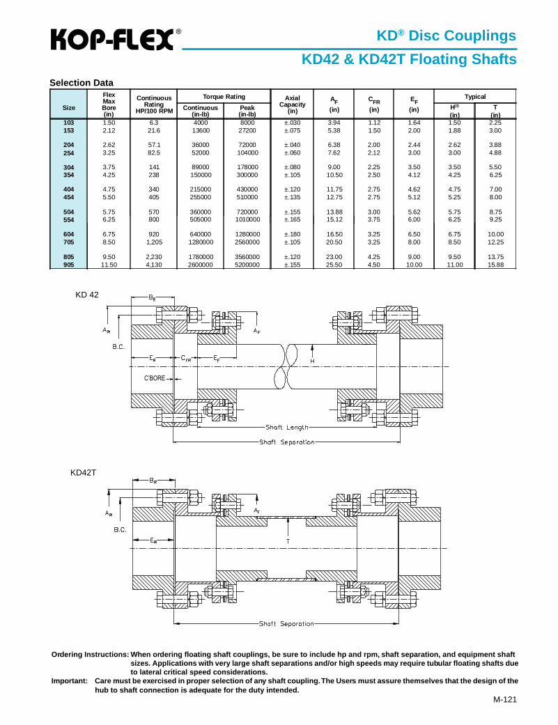
®
M-121
KD® Disc Couplings
KD42 & KD42T Floating Shafts
KD 42
KD42T
Selection Data
Ordering Instructions: When ordering floating shaft couplings, be sure to include hp and rpm, shaft separation, and equipment sh aftsizes. Applications with very large shaft separations and/or high speeds may require tubular floating shafts dueto lateral critical speed considerations.
Impor tant: Care must be exercised in proper selection of any shaft coupling. The Users must assure themselves that the design of thehub to shaft connection is adequate for the duty intended.
Size
FlexMaxBore(in)
ContinuousRating
HP/100 RPM
Torque Rating AxialCapacity
(in)
AF(in)
CFR(in)
EF(in)
Typical
Continuous(in-lb)
Peak(in-lb)
H(2)
(in)T
(in)103 1.50 6.3 4000 8000 ±.030 3.94 1.12 1.64 1.50 2.25153 2.12 21.6 13600 27200 ±.075 5.38 1.50 2.00 1.88 3.00
204 2.62 57.1 36000 72000 ±.040 6.38 2.00 2.44 2.62 3.88254 3.25 82.5 52000 104000 ±.060 7.62 2.12 3.00 3.00 4.88
304 3.75 141 89000 178000 ±.080 9.00 2.25 3.50 3.50 5.50354 4.25 238 150000 300000 ±.105 10.50 2.50 4.12 4.25 6.25
404 4.75 340 215000 430000 ±.120 11.75 2.75 4.62 4.75 7.00454 5.50 405 255000 510000 ±.135 12.75 2.75 5.12 5.25 8.00
504 5.75 570 360000 720000 ±.155 13.88 3.00 5.62 5.75 8.75554 6.25 800 505000 1010000 ±.165 15.12 3.75 6.00 6.25 9.25
604 6.75 920 640000 1280000 ±.180 16.50 3.25 6.50 6.75 10.00705 8.50 1,205 1280000 2560000 ±.105 20.50 3.25 8.00 8.50 12.25
805 9.50 2,230 1780000 3560000 ±.120 23.00 4.25 9.00 9.50 13.75905 11.50 4,130 2600000 5200000 ±.155 25.50 4.50 10.00 11.00 15.88
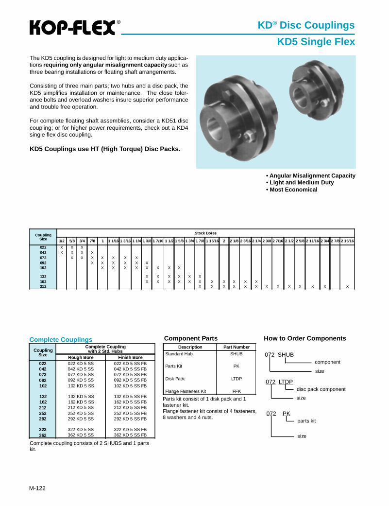
®
M-122
The KD5 coupling is designed for light to medium duty applica-tions requiring only angular misalignment capacity such asthree bearing installations or floating shaft arrangements.
Consisting of three main parts; two hubs and a disc pack, theKD5 simplifies installation or maintenance. The close toler-ance bolts and overload washers insure superior performanceand trouble free operation.
For complete floating shaft assemblies, consider a KD51 disccoupling; or for higher power requirements, check out a KD4single flex disc coupling.
KD5 Couplings use HT (High Torque) Disc Packs.
KD® Disc Couplings
KD5 Single Flex
• Angular Misalignment Capacity• Light and Medium Duty• Most Economical
CouplingSize
Complete Couplingwith 2 Std. Hubs
Rough Bore Finish Bore022 022 KD 5 SS 022 KD 5 SS FB042 042 KD 5 SS 042 KD 5 SS FB072 072 KD 5 SS 072 KD 5 SS FB092 092 KD 5 SS 092 KD 5 SS FB102 102 KD 5 SS 102 KD 5 SS FB
132 132 KD 5 SS 132 KD 5 SS FB162 162 KD 5 SS 162 KD 5 SS FB212 212 KD 5 SS 212 KD 5 SS FB252 252 KD 5 SS 252 KD 5 SS FB292 292 KD 5 SS 292 KD 5 SS FB
322 322 KD 5 SS 322 KD 5 SS FB362 362 KD 5 SS 362 KD 5 SS FB
Complete Couplings Component Parts
Complete coupling consists of 2 SHUBS and 1 partskit.
Description Part Number
Standard Hub SHUB
Parts Kit PK
Disk Pack LTDP
Flange Fasteners Kit FFK
Parts kit consist of 1 disk pack and 1fastener kit.Flange fastener kit consist of 4 fasteners,8 washers and 4 nuts.
How to Order Components
072 LTDP
size
disc pack component
072 PK
size
parts kit
072 SHUB
size
component
CouplingSize
Stock Bores
1/2 5/8 3/4 7/8 1 1 1/16 1 3/16 1 1/4 1 3/8 1 7/16 1 1/2 1 5/8 1 3/4 1 7/8 1 15/16 2 2 1/8 2 3/16 2 1/4 2 3/8 2 7/16 2 1/2 2 5/8 2 11/16 2 3/4 2 7/8 2 15/16
022 X X X042 X X X X072 X X X X X X X092 X X X X X X102 X X X X X X X X
132 X X X X X X162 X X X X X X X X X X X212 X X X X X X X X X X X X X
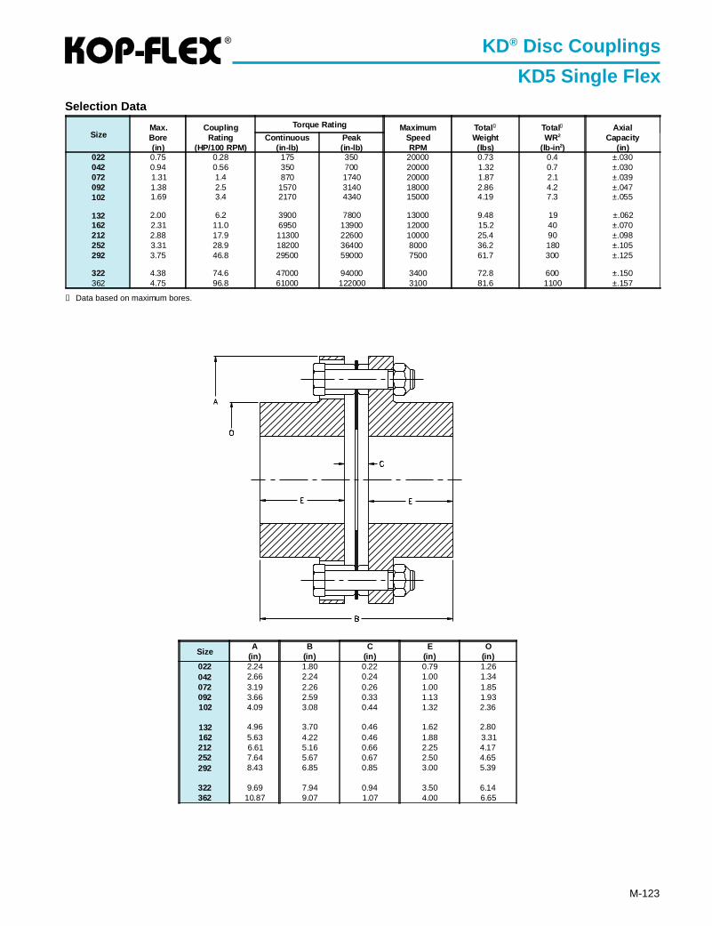
®
M-123
KD® Disc Couplings
KD5 Single Flex
SizeA
(in)B
(in)C
(in)E
(in)O
(in)022 2.24 1.80 0.22 0.79 1.26042 2.66 2.24 0.24 1.00 1.34072 3.19 2.26 0.26 1.00 1.85092 3.66 2.59 0.33 1.13 1.93102 4.09 3.08 0.44 1.32 2.36
132 4.96 3.70 0.46 1.62 2.80162 5.63 4.22 0.46 1.88 3.31212 6.61 5.16 0.66 2.25 4.17252 7.64 5.67 0.67 2.50 4.65292 8.43 6.85 0.85 3.00 5.39
322 9.69 7.94 0.94 3.50 6.14362 10.87 9.07 1.07 4.00 6.65
Selection Data
SizeMax.Bore(in)
CouplingRating
(HP/100 RPM)
Torque Rating MaximumSpeedRPM
Total ➀
Weight(lbs)
Total➀
WR2
(lb-in 2)
AxialCapacity
(in)Continuous
(in-lb)Peak(in-lb)
022 0.75 0.28 175 350 20000 0.73 0.4 ±.030042 0.94 0.56 350 700 20000 1.32 0.7 ±.030072 1.31 1.4 870 1740 20000 1.87 2.1 ±.039092 1.38 2.5 1570 3140 18000 2.86 4.2 ±.047102 1.69 3.4 2170 4340 15000 4.19 7.3 ±.055
132 2.00 6.2 3900 7800 13000 9.48 19 ±.062162 2.31 11.0 6950 13900 12000 15.2 40 ±.070212 2.88 17.9 11300 22600 10000 25.4 90 ±.098252 3.31 28.9 18200 36400 8000 36.2 180 ±.105292 3.75 46.8 29500 59000 7500 61.7 300 ±.125
322 4.38 74.6 47000 94000 3400 72.8 600 ±.150362 4.75 96.8 61000 122000 3100 81.6 1100 ±.157
➀ Data based on maximum bores.
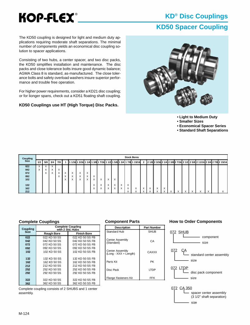
®
M-124
The KD50 coupling is designed for light and medium duty ap-plications requiring moderate shaft separations. The minimalnumber of components yields an economical disc coupling so-lution to spacer applications.
Consisting of two hubs, a center spacer, and two disc packs,the KD50 simplifies installation and maintenance. The discpacks and close tolerance bolts insure good dynamic balance;AGMA Class 8 is standard, as-manufactured. The close toler-ance bolts and safety overload washers insure superior perfor-mance and trouble free operation.
For higher power requirements, consider a KD21 disc coupling;or for lionger spans, check out a KD51 floating shaft coupling.
KD50 Couplings use HT (High Torque) Disc Packs.
KD® Disc Couplings
KD50 Spacer Coupling
• Light to Medium Duty• Smaller Sizes• Economical Spacer Series• Standard Shaft Separations
Description Part NumberStandard Hub SHUB
Center Assembly(Standard) CA
Center Assembly(Long - XXX = Length) CAXXX
Parts Kit PK
Disc Pack LTDP
Flange Fasteners Kit FFK
CouplingSize
Complete Couplingwith 2 Std. Hubs
Rough Bore Finish Bore022 022 KD 50 SS 022 KD 50 SS FB042 042 KD 50 SS 042 KD 50 SS FB072 072 KD 50 SS 072 KD 50 SS FB092 092 KD 50 SS 092 KD 50 SS FB102 102 KD 50 SS 102 KD 50 SS FB
132 132 KD 50 SS 132 KD 50 SS FB162 162 KD 50 SS 162 KD 50 SS FB212 212 KD 50 SS 212 KD 50 SS FB252 252 KD 50 SS 252 KD 50 SS FB292 292 KD 50 SS 292 KD 50 SS FB
322 322 KD 50 SS 322 KD 50 SS FB362 362 KD 50 SS 362 KD 50 SS FB
Complete Couplings Component Parts How to Order Components
072 LTDP
size
disc pack component
072 CA 350
size
spacer center assembly(3 1/2” shaft separation)
072 SHUB
size
component
072 CA
size
standard center assembly
Complete coupling consists of 2 SHUBS and 1 centerassembly.
CouplingSize
Stock Bores
1/2 5/8 3/4 7/8 1 1 1/16 1 3/16 1 1/4 1 3/8 1 7/16 1 1/2 1 5/8 1 3/4 1 7/8 1 15/16 2 2 1/8 2 3/16 2 1/4 2 3/8 2 7/16 2 1/2 2 5/8 2 11/16 2 3/4 2 7/8 2 15/16
022 X X X042 X X X X072 X X X X X X X092 X X X X X X102 X X X X X X X X
132 X X X X X X162 X X X X X X X X X X X212 X X X X X X X X X X X X X
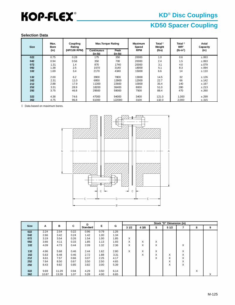
®
M-125
KD® Disc Couplings
KD50 Spacer CouplingSelection Data
➀ Data based on maximum bores.
Size A B C DStandard E G
Stock "D" Dimension (in)
3 1/2 4 3/8 5 5 1/2 7 8 9
022 2.24 2.54 0.22 0.96 0.79 1.26042 2.66 3.42 0.24 1.42 1.00 1.34072 3.19 3.54 0.26 1.54 1.00 1.85 X092 3.66 4.11 0.33 1.85 1.13 1.93 X X X102 4.09 4.73 0.44 2.09 1.32 2.36 X X X X
132 4.96 5.68 0.46 2.44 1.62 2.80 X X X X162 5.63 6.48 0.46 2.72 1.88 3.31 X X X X212 6.61 7.57 0.66 3.07 2.25 4.17 X X X252 7.64 8.50 0.67 3.50 2.50 4.65 X X292 8.43 9.82 0.85 3.82 3.00 5.39 X X
322 9.69 11.29 0.94 4.29 3.50 6.14 X362 10.87 13.28 1.07 5.28 4.00 6.65 X
SizeMax.Bore(in)
CouplingRating
(HP/100 RPM)
Max.Torque Rating MaximumSpeedRPM
Total ➀
Weight(lbs)
Total ➀
WR2
(lb-in 2)
AxialCapacity
(in)Continuous(in-lb)
Peak(in-lb)
022 0.75 0.28 175 350 20000 1.0 0.6 ±.063042 0.94 0.56 350 700 20000 2.4 1.5 ±.063072 1.31 1.4 870 1740 20000 3.1 4.0 ±.079092 1.38 2.5 1570 3140 18000 5.1 8.3 ±.094102 1.69 3.4 2170 4340 15000 6.6 14 ±.110
132 2.00 6.2 3900 7800 13000 14.5 32 ±.126162 2.31 11.0 6950 13900 12000 22.7 66 ±.142212 2.88 17.9 11300 22600 10000 35.4 140 ±.197252 3.31 28.9 18200 36400 8000 51.0 280 ±.213292 3.75 46.8 29500 59000 7500 88.4 470 ±.260
322 4.38 74.6 47000 94000 3400 121.0 1,000 ±.299362 4.75 96.8 61000 122000 3100 132.0 2,000 ±.315
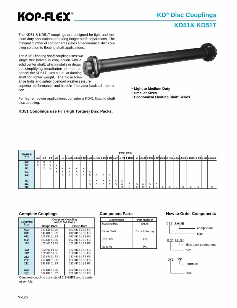
®
M-126
The KD51 & KD51T couplings are designed for light and me-dium duty applications requiring longer shaft separations. Theminimal number of components yields an economical disc cou-pling solution to floating shaft applications.
The KD51 floating shaft coupling uses twosingle flex halves in conjunction with asolid center shaft, which installs or dropsout simplifying installation or mainte-nance; the KD51T uses a tubular floatingshaft for lighter weight. The close toler-ance bolts and safety overload washers insuresuperior performance and trouble free zero backlash opera-tion.
For higher power applications, consider a KD41 floating shaftdisc coupling.
KD51 Couplings use HT (High Torque) Disc Packs.
KD® Disc Couplings
KD51& KD51T
• Light to Medium Duty• Smaller Sizes• Economical Floating Shaft Series
CouplingSize
Complete Couplingwith 2 Std. Hubs
Rough Bore Finish Bore022 022 KD 51 SS 022 KD 51 SS FB042 042 KD 51 SS 042 KD 51 SS FB072 072 KD 51 SS 072 KD 51 SS FB092 092 KD 51 SS 092 KD 51 SS FB102 102 KD 51 SS 102 KD 51 SS FB
132 132 KD 51 SS 132 KD 51 SS FB162 162 KD 51 SS 162 KD 51 SS FB212 212 KD 51 SS 212 KD 51 SS FB252 252 KD 51 SS 252 KD 51 SS FB292 292 KD 51 SS 292 KD 51 SS FB
322 322 KD 51 SS 322 KD 51 SS FB362 362 KD 51 SS 362 KD 51 SS FB
Complete Couplings Component Parts
Complete coupling consists of 2 SHUBS and 1 centerassembly.
Description Part NumberStandard Hub SHUB
CenterShaft Consult Factory
Disc Pack LTDP
Parts Kit PK
CouplingSize
Stock Bores
1/2 5/8 3/4 7/8 1 1 1/16 1 3/16 1 1/4 1 3/8 1 7/16 1 1/2 1 5/8 1 3/4 1 7/8 1 15/16 2 2 1/8 2 3/16 2 1/4 2 3/8 2 7/16 2 1/2 2 5/8 2 11/16 2 3/4 2 7/8 2 15/16
022 X X X042 X X X X072 X X X X X X X092 X X X X X X102 X X X X X X X X
132 X X X X X X162 X X X X X X X X X X X212 X X X X X X X X X X X X X
How to Order Components
072 LTDP
size
disc pack component
072 PK
size
parts kit
072 SHUB
size
component
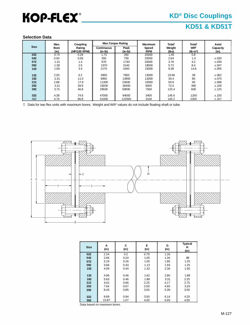
®
M-127
KD® Disc Couplings
KD51 & KD51T
Data based on maximum bores.
Selection Data
① Data for two flex units with maximum bores. Weight and WR2 values do not include floating shaft or tube.
SizeMax.Bore(in)
CouplingRating
(HP/100 RPM)
Max.Torque Rating MaximumSpeedRPM
Total 1
Weight(lbs)
Total 1
WR2
(lb-in 2)
AxialCapacity
(in)Continuous
(in-lb)Peak(in-lb)
022 0.75 0.28 1.75 350 20000 1.46 0.8042 0.94 0.56 350 700 20000 2.64 1.4 ±.030072 1.31 1.4 870 1740 20000 3.76 4.2 ±.039092 1.38 2.5 1570 3140 18000 5.72 8.4 ±.047102 1.69 3.4 2170 4340 15000 8.38 14.6 ±.055
132 2.00 6.2 3900 7800 13000 19.96 38 ±.062162 2.31 11.0 6950 13900 12000 30.4 80 ±.070212 2.88 17.9 11300 22600 10000 50.8 90 ±.098252 3.31 28.9 18200 36400 8000 72.4 360 ±.105292 3.75 46.8 29500 59000 7500 123.4 600 ±.125
322 4.38 74.6 47000 94000 3400 145.6 1200 ±.150362 4.75 96.8 61000 122000 3100 163.2 2200 ±.157
Size A(in)
C(in)
E(in)
G(in)
TypicalH
(in)022 2.24 0.2 0.79 1.26042 2.66 0.24 1.00 1.34 .88072 3.19 0.26 1.00 1.85 1.25092 3.66 0.33 1.13 1.93 1.25102 4.09 0.44 1.32 2.36 1.50
132 4.96 0.46 1.62 2.80 1.88162 5.63 0.46 1.88 3.31 2.25212 6.61 0.66 2.25 4.17 2.75252 7.64 0.67 2.50 4.65 3.25292 8.43 0.85 3.00 5.39 3.50
322 9.69 0.94 3.50 6.14 4.25362 10.87 1.07 4.00 6.65 4.50
H

![Kop-Flex KD Disc Couplings Metric - AHR International ball ... · 104 MT disc pack [ Medium Torque ] unitized, 3 bolt disc with “prestretch” bushings that get pressed into the](https://img.pdfslide.us/doc/110x75/5bd5a7d909d3f25d3e8c1d4d/kop-flex-kd-disc-couplings-metric-ahr-international-ball-104-mt-disc-pack.jpg)