Embed Size (px)
Citation preview
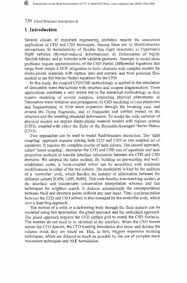
Coupling of CFD and CSD methodologies for modeling blast and structural response
J.D. ~ a u m ' , E.L. ~estreau' , H. LUO', R. ~ohner ' , D. ~elessone', C. charman', M.E. ~ i l t r u d ~ & Y. s o h 2 l Center for Applied Computational Sciences, ASG, SAIC, USA 2 Defense Threat Reduction Agency/TDACS, USA
Abstract
This paper describes recent algorithm developments and applications of a program that couples parallel Computational Fluid Dynamics (CFD) and Computational Structural Dynamics (CSD) methodologies. FEFL098 is the CFD code used while DYNA3D handles the CSD portion. FEFL098 solves the time-dependent compressible Euler and Reynolds-Averaged Navier-Stokes equations on an unstructured mesh of tetrahedral elements. DYNA3D solves explicitly the large deformation, large strain formulation equations on an unstructured grid composed of bricks and hexahedral elements. While the initial coupled algorithm used the so-called "glued-mesh" approach, where the CFD and CSD faces match identically, failure of this approach to model severe structural deformation, as well as crack propagation in steel and concrete, led us to the development of the so-called "embedded-mesh" approach. Here, the CSD objects float through the CFD domain. While each approach has its own advantages, limitations, and deficiencies, the embedded approach was proven to be superior for the class of problems modeled here. Critical application of both approaches are described, including weapon detonation and fragmentation, airblast interaction with a reinforced concrete wall, and fragment/airblast interaction with a steel wall. The final application models the interaction of an external airblast with a generic steel ship.
Transactions on the Built Environment vol 71, © 2004 WIT Press, www.witpress.com, ISSN 1743-3509
330 Fluid Structure Interaction 11
1 Introduction
Several classes of important engineering problems require the concurrent application of CFD and CSD techniques. Among these are: a) Shocklstructure interactions; b) Aeroelasticity of flexible thin flight structures; c) Hypersonic flight vehicles (thermal-induced deformations); d) Deformation of highly flexible fabrics; and e) Vehicles with variable geometry. Attempts to model these problems require approximations of the CSD Partial Differential Equations that range from simple 6 DOF integration to finite elements with complex models for elasto-plastic materials with rupture laws and contact, and from potential flow models to the full Navier-Stokes equations for the CFD.
In this study, the coupled CFDJCSD methodology is applied to the simulation of detonation wave interactions with structure and weapon fragmentation. These applications constitute a very severe test to the numerical methodology as they require modeling of several complex, interacting physical phenomena: a) Detonation wave initiation and propagation; b) CSD modeling of case expansion and fragmentation; c) Blast wave expansion through the breaking case, and around the flying fragments; and e) Fragments and airblast impact on the structure and the resulting structural deformation. To model the wide variation of physical models we require elasto-plastic material models with rupture criteria (CSD), coupled with either the Euler or the Reynolds-Averaged Navier-Stokes (CFD).
Two approaches can be used to model fluidlstructure interaction. The 'tight coupling' approach requires solving both CFD and CSD as one coupled set of equations. It requires the complete rewrite of both solvers. The second approach, called 'loose coupling', decouples the CFD and CSD sets of equations and uses projection methods to transfer interface information between the CFD and CSD domains. We adopted the latter method. By building on pre-existing and well- established codes, a loose-coupled solver can be assembled with minimum modifications to either of the two solvers. The modularity is kept by the addition of a 'controller' code, which handles the transfer of information between the different solvers [Ce98, Lo95, Ba961. This code handles non-matching meshes at the interface and incorporates conservative interpolation schemes and fast techniques for neighbor search. It deduces automatically the correspondence between fluid and structure points without any user input. Time synchronization between the CFD and CSD solvers is also managed by the controller code, which uses a leap-frog approach.
The motion of a solid or a deforming body through the fluid domain can be modeled using two approaches: the glued approach and the embedded approach. The glued approach requires the CFD surface grid to match the CSD Surfaces. The meshes do not need to be identical at the interface. When the CSD moves across the CFD domain, the CFD tracking boundaries also move and deform the volume mesh they are based on. This, in turn, triggers expensive meshing techniques, which are delayed as much as possible by the use of complex mesh movement techniques and ALE formulation.
Transactions on the Built Environment vol 71, © 2004 WIT Press, www.witpress.com, ISSN 1743-3509
Fluid Structure Interaction I1 33 1
In the second approach, the embedded CSD mesh floats through the CFD domain without bodylsurface conformance. The faster Eulerian formulation (rather than the slower ALE) is used while the only extra intensive steps involve the identification of the crossed edges and proper modeling of the boundary conditions. On the negative side, this methods requires the use of new boundary conditions of first and maybe second order, which are more complex. The penetration of a single CFD element by a multitude of CSD shells can also create problems and must also be addressed separately.
Over the past several years we have developed and successfully applied the traditional glued approach in several investigations [Ba98, BaOl, Lo921. However, this approach has failed recently for some simulations involving singular points, as well as for cases where initially orthogonal steel plates were deformed such that the core angles became exceedingly small, too small for the contact algorithm from preventing contact and penetration. Moreover, for applications such as crack propagation in steel plates or cased weapons under explosive loading which require frequent CPU-intensive topology reconstruction, in addition to super-fine resolution required to properly model crack growth in concrete or steel, this approach became prohibitively expensive (CPU-wise). Finally, the meshing procedure itself may fail due to bad elements enforced by the geometry. These shortcomings of the glued approach are, conversely, the strengths of the embedded approach, where the bodies float through the CFD mesh, as the distance between them, even at contact, poses no difficulty to the CFD solution.
The development of the embedded approach required the following major steps which use the existing 3-D CFD mesh and the wetted CSD faces: 1) Identify CFD edges cut by the CSD faces and mask CFD edges and points; 2) Impose new boundary conditions; 3) Modify the geometry boundary point arrays; 4) Extrapolate the solution near the boundaries; and 5) Develop new display tools. Due to space limitations, only some of these will be discussed here.
1.1 The current numerical methodology
Automatic unstructured mesh surface and volume generation has reached a high level of maturity over the past several years. Very complex shapes can now be meshed in matter of hours once the CAD model is properly prepared [Ba93, Ba95, Ba961. However, assembling the CAD definition of the model remains a bottleneck, consuming a large amount of man-hours. This led to the development of dedicated graphic pre-processor and post-processor tools, which efficiently generate appropriate CAD models suitable to the CFD and CSD mesh generators.
Mesh generation for both CSD and CFD was performed using FRGEN3D [LOSS]. This unstructured grid generator is based on the advancing front method. The CFD mesh is composed of triangular (surface) and tetrahedral (volume) elements. The CSD mesh includes beams, triangular or quad shells and bricks for the solids. The quads shells are the result of aggregation of triangles while the
Transactions on the Built Environment vol 71, © 2004 WIT Press, www.witpress.com, ISSN 1743-3509
332 Fluid Structure Interaction 11
bricks are the subdivision of tetrahedral elements followed by smoothing techniques. Although the angles of a typical hex are less than perfect, extensive testing against perfect-angle bricks for both linear and nonlinear cases, produced identical results. This, nevertheless, necessitated the replacement of the Belytschko-Tsay [86] hourglass control model (default model in DYNA3D [wh91]), with the Flanagan-Belytschko hourglass control model (model 3 in DYNA3D), incurring a 30% performance penalty.
The flow solver employed is FEFL098, a 3-D adaptive, unstructured, edge- based hydro-solver based on the Finite-Element Method Flux-Corrected Transport (FEM-FCT) concept [Lo92]. It solves the Arbitrary Lagrangean- Eulerian (ALE) formulation of the Euler and Reynolds-averaged turbulent, Navier-Stokes equations. The high order scheme used is the consistent-mass Taylor-Galerkin algorithm. Combined with a modified second-order Lapidus artificial viscosity scheme, the resulting scheme is second-order accurate in space, and fourth-order accurate in phase. The spatial mesh adaptation is based on local H-refinement, where the refinementldeletion criterion is a modified H2- seminorm [L0921 based on a user-specified unknown. Most of shock wave propagation cases require the use of a blend of density and energy. FEFL098 supports various equations of states including real air, water, SESAME and JWL with afterburning. Particles can also be used. They are treated as a solid phase, exchanging mass, momentum and energy with the fluid. For cases where body motions induce large mesh deformation, several automatic remeshing techniques can be used.
The structural dynamics solver is DYNA3D [Wh91], an unstructured, explicit finite element code. DYNA3D is well suited for modeling large deformations and provides a good base for non-linear materials with elasto-plastic compartmental laws with rupture. DYNA3D incorporates a large library of materials and various equations-of-state, as well as many kinematic options, such as slidelines and contacts. Furthermore, DYNA3D is a well proven and benchmarked solver used extensively in the CSD community.
2 Numerical results
2.1 Weapon fragmentation studies
The coupled technology has been applied to the simulation of the detonation and fragmentation of an experimental weapon that hangs tip-down at the center in a reinforced concrete room. The thick-walled steel weapon is top (i.e., base) ignited. The detonation front propagates from the base to the tip at the C-J detonation velocity prescribed in the detonation model (essentially, the program burn model of DYNA3D).
Several CSD meshes of this weapon were tested, using either 8-node hexahedral elements or brick-like parallelepipedal elements, and varying the number of elements from 748 to 8228. 748 brick elements with a single element across the thickness was used for the simulation with the glued approach. The fragment size distribution for the glued simulation was prescribed based on arena
Transactions on the Built Environment vol 71, © 2004 WIT Press, www.witpress.com, ISSN 1743-3509
Fluid Structure Interaction I1 333
test data. Four elements across were used for the embedded, where recently developed first-principles fragmentation model [Pe99] was used to model the break-up of the casing.
After ignition, as the detonation wave propagates from the base to the tip, the high-pressure detonation products force the case to expand. The structural elements fail once the element strain computed at the center of each element exceeds 100%. Each failing fragment is then treated as a separate rigid body. A 6 DOF integrator linked to the contact algorithms computes their trajectories. For the glued approach, the failure of bricks triggers automatic remeshing phases to fill up the narrow gaps separating the fragments. The gaps, which should have been of the order of millimeters, are artificially increased to avoid introduction of tiny fluid elements with small integration times. The remeshing (due to topology change) is a CPU intensive process and is allowed to occur only every 5-8 PS.
Even the usage of adaptive refinement and automatic placement of sources wherever needed for modeling the small spacing, did not significantly reduce the high computational cost.
During case expansion, the internal mesh velocity significantly exceeds the external velocity, resulting in case thinning. On average, while the CG of the element experiences a 100% strain (break-up criteria), the internal face expands about 145-160%, compared to about 70-80% for the external face. This indicates that during a significant portion of the expansion period, the internal face velocity is about twice the external face velocity. Once a fragment breaks apart, it is treated as a rigid body.
Figure 1 shows a comparison between the glued approach (Fig la) and the embedded approach (Figs I b and lc). The first approach did not allow for the application of a physically-correct crack propagation model, as each crack had to be modeled with at least 4-6 fluid elements across the narrow gap, at a prohibitive computational cost. The fragments had to be pre-defined, hence precluding the modeling of weapons for which there is no arena data. In addition, the break-up of each fragment was a topology-changing event, requiring global remeshing at a fairly high computational cost, even when performed in parallel using a parallelized grid generation scheme. In comparison, the embedded approach allows both the treatment of crack propagation and the formation of small fragments. Thus, the cracking model automatically determines the size of the fragments. The results shown in Figs lc-e demonstrate: 1) The randomness of the size of the fragments; 2) The narrow cracks between the fragments, some of which are very small; 3) The large number of fragments modeled, a simulation that would have been computationally prohibitive with the glued approach; 4) Mesh adaptation to both the structure (smaller elements within the cracks will yield more accurate pressure relief and detonation products expansion) and density gradients; and 5) Most fragments reach about the same velocity (within a range of about 15%), in agreement with available experimental data.
Transactions on the Built Environment vol 71, © 2004 WIT Press, www.witpress.com, ISSN 1743-3509
334 Fluid Structure Interaction 11
Fig 1 : Comparison of glued and embedded CSD schemes applied to the weapon fragmentation study.
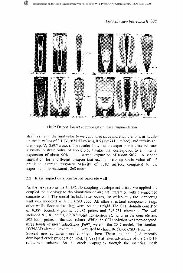
Figures 2a through 2d show a sequence of snapshots obtained in a simulation that used the glued mesh approach. At each time, the panel shows the pressure and CFD mesh velocity contours on a planar cut through the weapon, and the CSD fragment velocity contours. Figure 2a at 13 1 ps) shows detonation wave propagation down (from base to tip) as a planar front, and the radial expansion of the case.
The first fragment break-up occurs at 94 ps, at the upper row attached to the heavy base. While the base itself does not fragment, as it does not expand significantly, the row of elements below fails due to shear, not tension. Similar failure occurs for the fragment layer above the nose cone. (Fig 2c at 370 p ) . Detonation was completed at about t=263 ps and the shock reflected upward (Fig 2b).
The fragments achieve their terminal velocity between 120 and 150 ps after the detonation front passage. The final mass-averaged fragment velocity obtained for this simulation, using a strain break-up value of 1.0, was 787.6 mlsec. The experimental. measured value was 752 mlsec. To examine the role of the break-up
Transactions on the Built Environment vol 71, © 2004 WIT Press, www.witpress.com, ISSN 1743-3509
Fluid Structure Interaction I1 335
Fig 2: Detonation wave propagation; case fragmentation
strain value on the final velocity we conducted three more simulations, at break- up strain values of 0.1 (Vf675.53 misec), 0.5 (Vy741 .8 mlsec), and infinity (no break-up, Vc859.7 mlsec). The results show that the experimental data indicates a break-up strain value of about 0.6, a value that corresponds to an internal expansion of about 90%, and external expansion of about 50%. A second simulation for a different weapon that used a break-up strain value of 0.6 predicted average fragment velocity of 1282 msisec, compared to the experimentally measured 1260 mlsec.
2.2 Blast impact on a reinforced concrete wall
As the next step in the CFDICSD coupling development effort, we applied the coupled methodology to the simulation of airblast interaction with a reinforced concrete wall. The model included two rooms, for which only the connecting wall was modeled with the CSD code. All other structural components (e.g., other walls, floor and ceiling) were treated as rigid. The CFD domain consisted of 9,387 boundary points, 55,281 points and 296,751 elements. The wall included 8 1,10 1 nodes, 69,048 solid hexahedron elements in the concrete and 598 beam points in the steel rebars. While the CFD solution was non-adapted, three levels of mesh adaptation [Pe97] were in the CSD model. The standard DYNA3D element erosion model was used to eliminate failed CSD elements. Several new schemes were employed here. These include: 1) A recently developed crack propagation model [Pe99] that takes advantage of the CSD H- refinement scheme. AS the crack propagates through the material, mesh
Transactions on the Built Environment vol 71, © 2004 WIT Press, www.witpress.com, ISSN 1743-3509
336 Fluid Structure Interaction 11
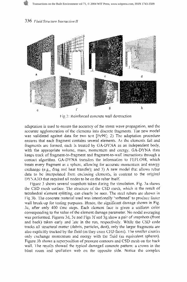
Fig 3: Reinforced concrete wall destruction
adaptation is used to ensure the accuracy of the stress wave propagation, and the accurate agglomeration of the elements into discrete fragments. The new model was validated against data for two test [Pe99]; 2) The adaptation procedure ensures that each fragment contains several elements. As the elements fail and fragments are formed, each is treated by GA-DYNA as an independent body, with the appropriate volume, mass, momentum and energy. GA-DYNA then keeps track of fragment-to-fragment and fragment-to-wall interactions through a contact algorithm. GA-DYNA transfers the information to FEFLO98, which treats every fragment as a sphere, allowing for accurate momentum and energy exchange (e.g., drag and heat transfer); and 3) A new model that allows rebar data to be interpolated from enclosing elements, in contrast to the original DYNA3D that required all nodes to be on the rebar itself.
Figure 3 shows several snapshots taken during the simulation. Fig. 3a shows the CSD mesh surface. The structure of the CSD mesh, which is the result of tetrahedral element splitting, can clearly be seen. The steel rebars are shown in Fig 3b. The concrete material used was intentionally 'softened' to produce faster wall break-up for testing purposes. Hence, the significant damage shown in Fig. 3c, after only 400 time steps. Each element face is given a uniform color corresponding to the value of the element damage parameter. No nodal averaging was performed. Figures 3d, 3e and Figs 3f and 3g show a pair of snapshots (front and back) taken early and late in the run, respectively. While the CSD code tracks all structural matter (debris, particles, dust), only the larger fragments are also explicitly tracked by the fluid (as they cross CFD faces). The smaller chunks only exchange momentum and energy with the fluid (as equivalent spheres). Figure 3h shows a superposition of pressure contours and CSD mesh on the back wall. The results showed the typical damaged concrete pattern: a crown in the blast room and spallation web on the opposite side. Notice the complex
Transactions on the Built Environment vol 71, © 2004 WIT Press, www.witpress.com, ISSN 1743-3509
Fluid Structure Interaction I1 337
connectivity through the concrete that allows the high pressure to emerge through the other side of the wall: from the peripheral crown to the centered spall zone. Three levels of mesh adaptation are shown in these figures. The adapted CSD mesh enables accurate prediction of the spallation, crack propagation, element failure and fragment formation, which expose the rebars on the spalled side.
2.3 Blast and fragment impact on a steel chamber
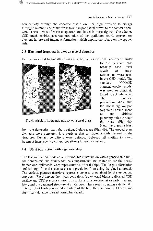
Here we modeled fragmentlairblast interaction with a steel wall chamber. Similar to the weapon case breakup case, three levels of mesh refinement were used in the CSD model. The standard DYNA3D element erosion model was used to eliminate failed CSD elements. The numerical predictions show that the impacting weapon fragments arrive ahead of the airblast, punching holes through
Fig 4: Airblastlfragments impact on a steel plate the plate ( ~ i ~ 4a).
Next, the pressure blast from the detonation tears the weakened plate apart (Figs 4b). The eroded plate elements were converted into particles that can interact with the rest of the structure. Contact conditions were enforced between all entities to avoid fragment interpenetrations and therefore a failure in meshing.
2.4 Blast interaction with a generic ship
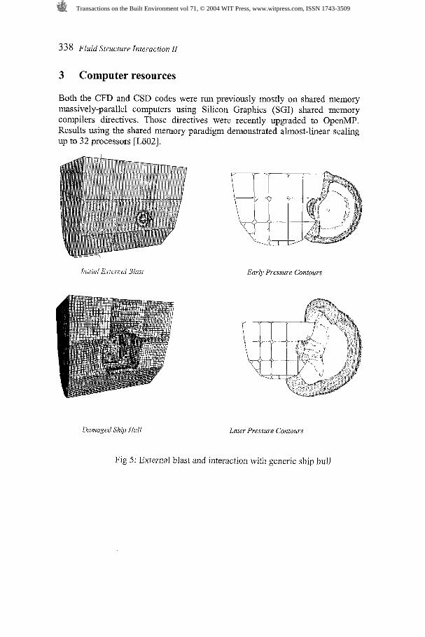
The last simulation modeled an external blast interaction with a generic ship hull. All dimensions and values for the compartments and materials for the decks, frames and bulkheads were representative of real ships. The large deformation and folding of metal sheets at corners precluded from using the glued approach. The various pictures therefore represent the results obtained by the embedded approach. Fig 5 depicts the initial conditions (an external blast), deformed CSD surface and CFD pressure contours on a planar cross-section at an early time and later, and the damaged structure at a late time. These results demonstrate that the exterior blast loading resulted in failure of the hull, three interior bulkheads, and significant damage to neighboring bulkheads.
Transactions on the Built Environment vol 71, © 2004 WIT Press, www.witpress.com, ISSN 1743-3509
338 Fluid Structure Interaction I1
3 Computer resources
Both the CFD and CSD codes were run previously mostly on shared memory massively-parallel computers using Silicon Graphics (SGI) shared memory compilers directives. Those directives were recently upgraded to OpenMP. Results using the shared memory paradigm demonstrated almost-linear scaling up to 32 processors rL0021.
h f i n i E~ tcnwl Bhrrr Early Pressure Contours
Dot~ra,ot:d Sllip Hull Later Pressure Contours
Fig 5: External blast and interaction with generic ship hull
Transactions on the Built Environment vol 71, © 2004 WIT Press, www.witpress.com, ISSN 1743-3509
Fluid Structure Interaction 11 339
4 Summary and conclusions
A recently developed loose-coupling algorithm that combines state-of-the-art Computational Fluid Dynamics (CFD) and Computational Structural Dynamics (CSD) methodologies, has been applied to the simulation of weapon detonation and fragmentation and blast and fragment impact on steel and concrete structures. A significant development described in this paper was the failure of the glued mesh approach to model the response of complex-geometry severely deforming steel-plate structure to a large blast. This forced the development of the embedded mesh approach, which is capable of handling these events. The results demonstrate the ability of the coupled methodology to handle these processes and yield results that are in good agreement with experimental data. In addition, these results demonstrate that for the class of problems modeled here, the embedded mesh approach is far superior to the glued mesh approach.
References
[Ba93] J.D. Baum, H. Luo, and R. Lohner - Numerical Simulation of a Blast Inside a Boeing 747; AIAA--93-3091 (1993).
[Ba95] J.D. Baum, H. Luo and R. Lohner - Numerical Simulation of Blast in the World Trade Center; AIAA-95-0085 (1995).
[Ba96] J.D. Baum, H. Luo, R. Lohner, C. Yang, D. Pelessone and C. Charman - A Coupled FluidlStructure Modeling of Shock Interaction with a Truck; AIAA-96-0795 (1 996).
[Ba98] J.D. Baum, H. Luo and R. Lohner - The Numerical Simulation of Strongly Unsteady Flows With Hundreds of Moving Bodies; AIAA-98- 0788 (1998).
[BaOl] J. D. Baum, et al., A Recent Developments of a Coupled CFDICSD Methodology, AIAA 2001 -261 8, Proc. 15th AIAA CFD Conf. Anaheim, CA (2001).
[Be861 T. Belytschko, and J.I. Lin - A Three-Dimensional Impact-Penetration Algorithm with Erosion; Computers and Structures, Vol. 25 No. I, p 95, 1986.
[Ce98] J.R. Cebral and R. Lohner - Conservative Load Transfer for Fluid- Structure-Thermal Simulations; Proc. 4th WCCM, Buenos Aires, Argentina, July (1998).
[L0881 R. Lohner and P. Parikh - Three-Dimensional Grid Generation by the Advancing Front Method; Int. J. Num. Meth. Fluids 8. 1135- 11 49(1988).
[L0921 R. Lohner and J.D. Baum - Adaptive H-Refinement on 3-D Unstructured Grids for Transient Problems; Int. J. Num. Meth. Fluids 14, 1407-1419 (1 992).
Transactions on the Built Environment vol 71, © 2004 WIT Press, www.witpress.com, ISSN 1743-3509
340 Fluid Structure Interaction 11
[L0951 R. Lohner, C. Yang, J. Cebral, J.D. Baum, H. Luo, D. Pelessone and C. Charman - Fluid-Structure Interaction Using a Loose Coupling Algorithm and Adaptive Unstructured Grids; AIAA-95-2259 (1995).
[L0021 R. Lohner et al, Advances in FEFLOI, AIAA-2002-1024, AIAA 40th Aerospace Sciences Meeting, Reno, NV (2002).
[Pe97] D. Pelessone, and C.M. Charman - An Adaptive Finite Element Procedure for Structural Analysis of Solids; 1997 ASME Pressure Vessels and Piping Conference, Orlando, Florida, July (1997).
[Pe99] D. Pelessone, C.M. Charman, R. Lohner and J.D. Baum - A new Crack Propagation Algorithm for modeling Weapon Fragmentation; in preparation.
[Wh91] R.G. Whirley and J.O. Hallquist - DYNA3D, A Nonlinear Explicit, Three-Dimensional Finite Element Code for Solid and Structural Mechanics - User Manual; UCRL-MA-107254 (1991), also Comp. Meth. Appl. Mech. Eng. 33, 725-757 (1982).
Transactions on the Built Environment vol 71, © 2004 WIT Press, www.witpress.com, ISSN 1743-3509