Embed Size (px)
Citation preview

Coupling and its Types
Function of Coupling
• Due to sagging problem of shaft, length ofcontinuous shaft is not kept more than 10meters
• To join two rotating shafts permanently,Couplings are used.
• Function of coupling is to join shaftspermanently.

Requirement of good Coupling
• It should transmit the full power from oneshaft to another.
• It should keep the shafts in perfect alignment.
• It should absorb the slight misalignment thatmay be present between the driver and driveshaft.
• It should be easy to connect and disconnect.
• It should have no projecting parts.

Basic Types of Coupling
1. Rigid Coupling- Cannot tolerate misalignmentbetween the axes, Do not absorbs shocks,Simple & inexpensive
2. Flexible coupling – Elements like bush or diskis used, which tolerate 0.5 degrees of angularmisalignment, Absorbs shocks and vibrations,Costlier than Rigid coupling

Rigid Couplings
1. Muff Coupling
2. Clamp Coupling or split muff coupling
3. Rigid Flange Coupling
Muff CouplingSplit Muff Coupling Flange Coupling
Design of Muff Coupling
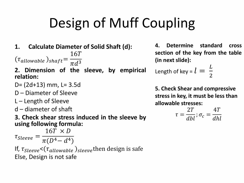
1. Calculate Diameter of Solid Shaft (d):
(𝜏𝑎𝑙𝑙𝑜𝑤𝑎𝑏𝑙𝑒 )𝑠ℎ𝑎𝑓𝑡=16𝑇
𝜋𝑑3
2. Dimension of the sleeve, by empiricalrelation:D= (2d+13) mm, L= 3.5dD – Diameter of SleeveL – Length of Sleeved – diameter of shaft3. Check shear stress induced in the sleeve byusing following formula:
𝜏𝑆𝑙𝑒𝑒𝑣𝑒 =16𝑇 × 𝐷
𝜋(𝐷4− 𝑑4)If, 𝜏𝑆𝑙𝑒𝑒𝑣𝑒<(𝜏𝑎𝑙𝑙𝑜𝑤𝑎𝑏𝑙𝑒 )𝑠𝑙𝑒𝑒𝑣𝑒then design is safeElse, Design is not safe
4. Determine standard crosssection of the key from the table(in next slide):
Length of key = 𝑙 =𝐿
2
5. Check Shear and compressive stress in key, it must be less than allowable stresses:
𝜏 =2𝑇
𝑑𝑏𝑙; 𝜎𝑐 =
4𝑇
𝑑ℎ𝑙

Design of Key
Length of Key, 𝑙 =𝐿
2
For rectangular key:
𝑤 𝒐𝒓 𝑏 =𝑑
4, ℎ =
𝑑
6
For square key:
𝑤 𝒐𝒓 𝑏 =𝑑
4, ℎ =
𝑑
4

Muff coupling Problem 1 :
Design a muff coupling to connect 2 steel shaftstransmitting 25kW power at 360 rpm. The shaftsand keys are made of plain carbon steel 30C8(Syt = Syc = 400 N/mm2). The sleeve is made ofgrey cast iron FG 200 (Sut= 200 N/mm2). Thefactor of safety for the shafts and key is 4. Forthe sleeve, the factor of safety is 6 based onultimate strength.
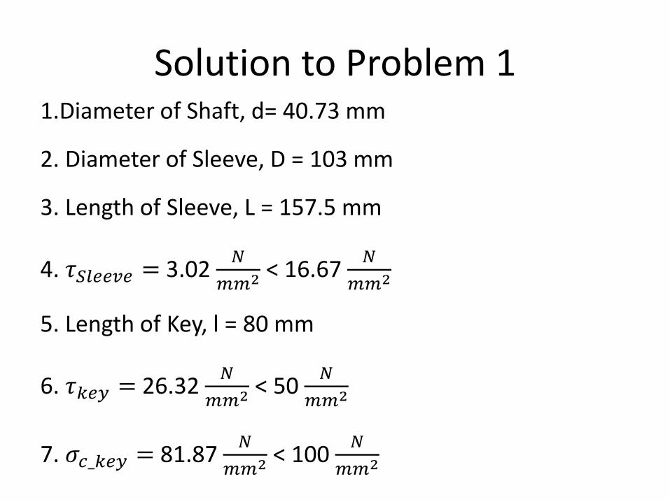
Solution to Problem 11.Diameter of Shaft, d= 40.73 mm
2. Diameter of Sleeve, D = 103 mm
3. Length of Sleeve, L = 157.5 mm
4. 𝜏𝑆𝑙𝑒𝑒𝑣𝑒 = 3.02 𝑁
𝑚𝑚2 < 16.67𝑁
𝑚𝑚2
5. Length of Key, l = 80 mm
6. 𝜏𝑘𝑒𝑦 = 26.32𝑁
𝑚𝑚2 < 50𝑁
𝑚𝑚2
7. 𝜎𝑐_𝑘𝑒𝑦 = 81.87𝑁
𝑚𝑚2 < 100𝑁
𝑚𝑚2

Clamp Coupling or split muff coupling or compression coupling
• Coupling sleeve in clamp coupling is made up of two halves that are clamped together with bolts.
• Number of bolts may be =4,8 etc. (multiples of four)
• Bolts are placed in the recesses formed in the sleeve halves.

Torque transmission by Clamp Coupling
• In clamp coupling Torque is transmitted by
1] Friction between sleeve halves & shaft
2] Shear resistance of keys
While in muff coupling Torque is transmitted by : Shear
resistance of key only

Design of Clamp Coupling
• For Sleeve halves,
D= outer Diameter of sleeve halves (mm)
L = length of sleeve (mm)
d= Diameter of shaft (mm)
1) D = 2.5 d
2) L= 3.5 d
Design of Clamp Coupling
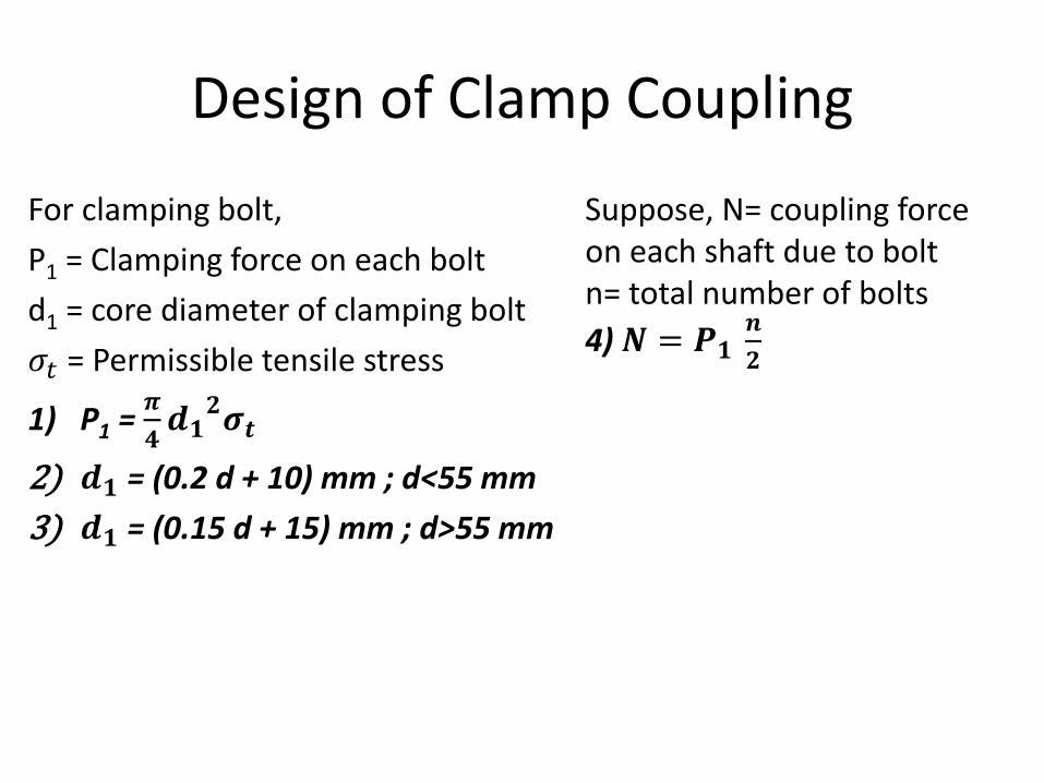
For clamping bolt,
P1 = Clamping force on each bolt
d1 = core diameter of clamping bolt
𝜎𝑡 = Permissible tensile stress
1) P1 =𝝅
𝟒𝒅𝟏
𝟐𝝈𝒕
2) 𝒅𝟏 = (0.2 d + 10) mm ; d<55 mm
3) 𝒅𝟏 = (0.15 d + 15) mm ; d>55 mm
Suppose, N= coupling force on each shaft due to boltn= total number of bolts
4)𝑵 = 𝑷𝟏𝒏
𝟐

Frictional Torque
• As there is friction between sleeve halves (having bolts which applies P1 force) & shaft
Torque, T = 𝜇 𝑁𝑑
2+ 𝜇 𝑁
𝑑
2= 𝜇 𝑁𝑑
𝑇 =𝜇 𝑑 𝑛 𝑃1
2

Split muff Coupling Problem 2
It is required to design a split muff coupling totransmit 50 kW power at 120 rpm. The shafts,key and coupling bolts are made of plain carbonsteel 30C8 (Syt = 400 N/mm2). The yield strengthin compression is 150% of the tensile strength.The factor of safety for the shafts, key and bolts is5. The number of clamping bolts is 8. The co-efficient of friction between sleeve halves andshaft is 0.3.
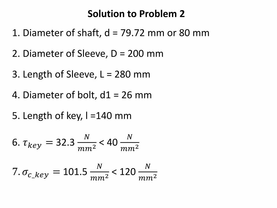
Solution to Problem 2
1. Diameter of shaft, d = 79.72 mm or 80 mm
2. Diameter of Sleeve, D = 200 mm
3. Length of Sleeve, L = 280 mm
4. Diameter of bolt, d1 = 26 mm
5. Length of key, l =140 mm
6. 𝜏𝑘𝑒𝑦 = 32.3𝑁
𝑚𝑚2 < 40 𝑁
𝑚𝑚2
7. 𝜎𝑐_𝑘𝑒𝑦 = 101.5𝑁
𝑚𝑚2 < 120𝑁
𝑚𝑚2
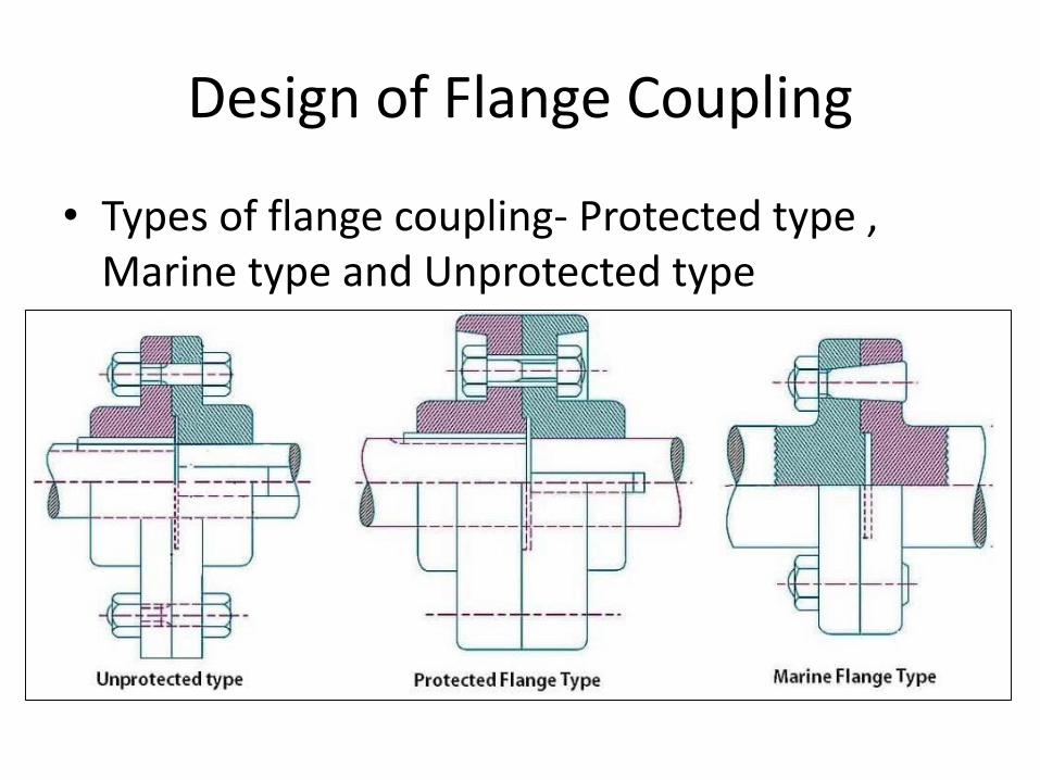
Design of Flange Coupling
• Types of flange coupling- Protected type , Marine type and Unprotected type

Design of Protected Type Flange Coupling
1. Outside diameter of hub, dh = 2d
2. Length of Hub or Length of key,lh = 1.5 d
3. Pitch circle diameter of Bolt, D=3d
4. Thickness of flanges, t= 0.5 d
5. Thickness of protecting rim, t1=0.25 d
6. Diameter of spigot and recess, dr = 1.5 d
7. Outside diameter of flange, Do= 4d+t1
d=shaft diameter in mm
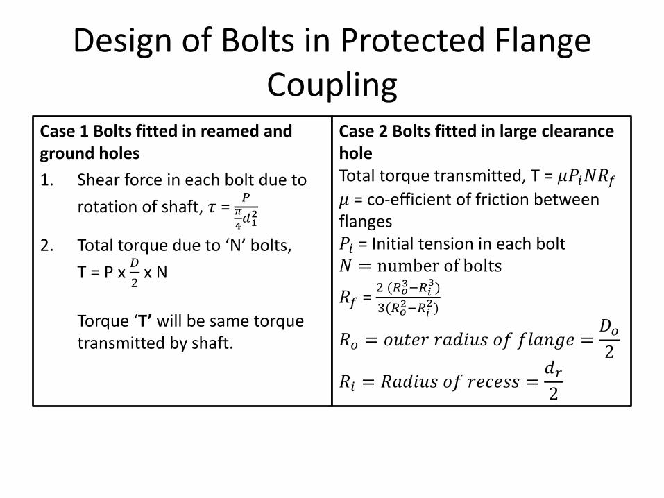
Design of Bolts in Protected Flange Coupling
Case 1 Bolts fitted in reamed and ground holes
1. Shear force in each bolt due to
rotation of shaft, 𝜏 = 𝑃
𝜋
4𝑑12
2. Total torque due to ‘N’ bolts,
T = P x 𝐷
2x N
Torque ‘T’ will be same torque transmitted by shaft.
Case 2 Bolts fitted in large clearance holeTotal torque transmitted, T = 𝜇𝑃𝑖𝑁𝑅𝑓𝜇 = co-efficient of friction between flanges𝑃𝑖 = Initial tension in each bolt𝑁 = number of bolts
𝑅𝑓 = 2 (𝑅𝑜
3−𝑅𝑖3)
3(𝑅𝑜2−𝑅𝑖
2)
𝑅𝑜 = 𝑜𝑢𝑡𝑒𝑟 𝑟𝑎𝑑𝑖𝑢𝑠 𝑜𝑓 𝑓𝑙𝑎𝑛𝑔𝑒 =𝐷𝑜2
𝑅𝑖 = 𝑅𝑎𝑑𝑖𝑢𝑠 𝑜𝑓 𝑟𝑒𝑐𝑒𝑠𝑠 =𝑑𝑟2

Design of Protected Flange coupling
1. Calculate Diameter of Solid Shaft (d):
(𝜏𝑎𝑙𝑙𝑜𝑤𝑎𝑏𝑙𝑒 )𝑠ℎ𝑎𝑓𝑡=16𝑇
𝜋𝑑32. Dimension of the sleeve, by empiricalrelation:Calculate all 7 dimensions shown in previousslide no. 183. Check shear stress induced in the hub byusing following formula:
𝜏ℎ𝑢𝑏 =16𝑇 × 𝑑ℎ
𝜋(𝑑ℎ4− 𝑑4)
If, 𝜏ℎ𝑢𝑏<(𝜏𝑎𝑙𝑙𝑜𝑤𝑎𝑏𝑙𝑒 )ℎ𝑢𝑏then design is safeElse, Design is not safe
4. Calculate the diameter of bolt, d1:a) Using Case 1 equation:
T = P x𝐷
2x N
b) Using Case 2 equation:
T = 𝜇𝑃𝑖𝑁𝑅𝑓 → Find 𝑃𝑖→ Find diameter of bolt
(𝑑1), Using 𝑃𝑖 =𝜋
4𝑑12𝜎𝑡,
𝜎𝑡 = Permissible tensile strength of boltmaterial

Problem 3 based on Flange coupling
A rigid coupling is used to transmit 20 kW powerat 720 rpm. There are four bolts and the pitchcircle diameter of the bolts is 125 mm. The bolts
are made of steel 45C8 (𝑆𝑦𝑡 = 380𝑁
𝑚𝑚2) and
factor of safety is 3. Assume Shear strength ,(𝑆𝑠𝑦 = 0.577 𝑆𝑦𝑡) and determine the diameter
of the bolts.
Case is reamed and ground holes. [CASE 1]

Solution to problem 3
1. Find Torque transmitted, Power = 2𝜋𝑁𝑇
60
2. Find Allowable shear stress in bolts, 𝜏𝑎𝑙𝑙 =𝑆𝑠𝑦
𝐹𝑂𝑆
3. Find load P transmitted due to torque , T= P x 𝐷
2x N
4. Using equation of shear stress for bolt, find
diameter of bolts, 𝜏𝑎𝑙𝑙 =𝑃
𝜋
4𝑑12