Embed Size (px)
Citation preview
IOP PUBLISHING JOURNAL OF PHYSICS D: APPLIED PHYSICS
J. Phys. D: Appl. Phys. 41 (2008) 025205 (10pp) doi:10.1088/0022-3727/41/2/025205
Coupled gas and ion transport inquadrupole interfacesM Jugroot1,3, C P T Groth1,4, B A Thomson2, V Baranov2, B A Collings2
and J B French2
1 Institute for Aerospace Studies, University of Toronto, Ontario, M3H 5T6, Canada2 MDS SCIEX, Concord, Ontario, L4K 4V8, Canada
E-mail: [email protected] and [email protected]
Received 12 October 2007Published 4 January 2008Online at stacks.iop.org/JPhysD/41/025205
AbstractThe transport of free ions through highly under-expanded jet flows of neutral gases and in thepresence of applied electric fields is investigated by continuum-based (fluid) numericalsimulations. In particular, numerical results are described which are relevant to ion flowsoccurring in quadrupole interfaces of mass spectrometer systems. A five-momentmathematical model and parallel multi-block numerical solution procedure are developed forpredicting the ion transport. The model incorporates the effects of ion–neutral collisionprocesses and is used in conjunction with a Navier–Stokes model and flow solver for theneutral gas to examine the key influences controlling the ion motion. The effects of the neutralgas flow, electric fields (both dc and rf) and flow field geometry on ion mobility are carefullyassessed. The capability of controlling the charged particle motions through a combination ofdirected neutral flow and applied electric field is demonstrated for these high-speed,hypersonic, jet flows. The neutral dynamics is shown to have a strong influence on the iontransport whereas the electric field imparts a more gradual effect. The combined effect of theapplied (dc and rf) electric field and neutral collision processes with the dilute neutral gasresults in a strong tendency for ion focusing towards the axis of symmetry, with the overallefficiency governed by the mass-to-charge ratio.
(Some figures in this article are in colour only in the electronic version)
1. Introduction
The ability to accurately predict and thereby understandthe often complex transport of charged particles through abackground neutral gas subject to electro-magnetic forcesis very important to furthering the understanding of manyadvanced technological processes including those associatedwith vapour deposition in material and semiconductorprocessing [1], electric space propulsion devices [2, 3],microsystems [4], plasma jets [5, 6] as well as space plasmas[7]. The transport of ions through rapidly expanding and/orjet flows is also very important to the operation of massspectrometers, such as liquid chromatography (LC)/massspectrometry (MS) systems used extensively in the traceanalysis of biological fluids for metabolites and natural
3 Assistant Professor, Royal Military College, Canada.4 Associate Professor, University of Toronto, Canada.
biopolymers [8, 9] and in drug design [10]. The LC/MSinstruments make use of an atmospheric pressure ionizationtechnique whereby sample ions are generated at atmosphericpressure from molecules which are contained in micro-droplets and the resulting ions are then transported fromthe atmospheric pressure conditions into a high vacuumsystem for spectroscopic analysis. The performance of themass spectrometers is highly dependent on the ion transportfrom the source region to the mass detectors. Gainingan improved understanding of ion-source flows and relatedtransport phenomena is an active area of research.
This study is concerned with the modelling of the transportof free ions through highly under-expanded jet flows of neutralgases under the influence of applied electric fields producedin the interface regions of quadrupole mass spectrometersystems. Quadrupole interfaces generally consist of a radio-frequency (rf) quadrupole as shown in figure 1. A variety
0022-3727/08/025205+10$30.00 1 © 2008 IOP Publishing Ltd Printed in the UK

J. Phys. D: Appl. Phys. 41 (2008) 025205 M Jugroot et al
Figure 1. Schematic diagrams of (LHS) an rf cylinder showing the electrode and insulator strip geometry and the more traditional,equivalent, four-rod quadrupole configuration (from Prestage [11]) and (RHS) the quadrupole interface showing orifice, skimmer andrf cylinder.
of quadrupole configurations are possible. In this study, twodifferent configurations are considered, namely, the traditionalfour-rod quadrupole configuration as shown in figure 1 aswell as a novel configuration consisting of a single hollowcylinder composed of alternating electrode and insulator stripsthat produce the rf-quadrupole field [11], also shown in thefigure. The region upstream of the orifice is at atmosphericpressure and, downstream of the quadrupole, a low pressureis maintained. Ions are transported by the neutral gas fromthe high-pressure reservoir through a small orifice and gasskimmer and then on through the rf quadrupole as shown infigure 1.
A five-moment continuum-based (fluid) model andparallel multi-block numerical solution procedure aredescribed for predicting the ion transport in the completequadrupole interface. The five-moment model has been usedsuccessfully in previous studies of ion transport in MS systemsby Jugroot et al [12, 13]. It provides ‘one-way’ couplingbetween the ion and neutral flows by incorporating the effectsof ion–neutral collision processes. It can also account for theeffects of externally applied electric fields. A parallel explicithigher-order Godunov-type finite-volume scheme is used tosolve the five-moment ion transport equations on a multi-blockquadrilateral mesh. The proposed scheme determines the iontransport in the quadrupole interface, given a precomputedneutral gas flow and electric potential.
2. Governing equations
2.1. Five-moment ion transport model
The transport of a mixture of a neutral gas and free ions isconsidered. This mixture is not formally treated as a plasma,but rather as a source of positively charged ions, for it isassumed that there are no free electrons (plasmas compriseneutral particles, ions and electrons and the charged particles’transport is generally tightly coupled by electric/magneticapplied/induced fields). For the purpose of this study, it is also
estimated and assumed that the ion number density is very lowcompared with that of the neutral gas such that the ions have anegligible effect on the neutral particles. Hence, the solution ofthe ion and neutral gas flows can be decoupled. The neutral gasflow field can be predetermined and then the prediction of theion motion can be carried out using this calculated neutral gassolution. A five-moment closure continuum approximationis used to model the motion of the ions through the moredense neutral gas [14–17]. This mathematical description isa single-temperature, near-equilibrium model that can takeinto account the effects of ion–neutral collision processesand applied external electric and magnetic forces. Ion self-collisions (ion–ion collision processes) are neglected in thisapproximation and hence the ion fluid stresses and heat fluxare assumed to be unimportant.
The governing transport equations of the five-momentmodel reflect the conservation of mass, momentum and energyand can be written in the non-conservative coordinate-freeform as∂ρi
∂t+ ∇ · (ρivi) = 0, (1)
∂vi
∂t+ (vi · ∇)vi +
1
ρi∇pi = Qi
miE +
Qi
mi(vi × B)
+∑
s
νis(vs − vi), (2)
∂pi
∂t+ (vi · ∇)pi + γipi(∇ · vi) = δpi
δt, (3)
where ρi = mini is the ion mass density, ni is the ion numberdensity, mi is the mass of the ion molecules, vi is the ionvelocity, pi = ρiRiTi = nikTi is the ion pressure, Ti isthe ion temperature, Ri is the ion ideal gas constant, k is theBoltzmann constant, γi is the ion specific heat ratio, Qi is theion particle charge and E and B are the external electric andmagnetic fields. Ion–neutral collision processes are modelledhere using a generalization of the so-called relaxation timeor the BGK (Bhatnagar, Gross and Krook) approximation for
2

J. Phys. D: Appl. Phys. 41 (2008) 025205 M Jugroot et al
the Boltzmann collision integral [14, 16–18]. In this modifiedrelaxation-time approach, the relaxation time is actually notconstant. Instead, the collision cross-section is assumed to beconstant and the collision frequency is taken to be dependenton the local macroscopic solution quantities (i.e. numberdensities and temperatures). The influences of the ion–neutralcollisional processes manifest themselves as source terms inthe ion momentum and energy equations, equations (2) and (3),respectively. These terms involve a sum over all neutral gasspecies, s, and depend on the momentum exchange collisionfrequency, νis . The energy or pressure source term, δpi/δt , isgiven by
δpi
δt=
∑s
ρimsνis
(mi + ms)2
[2k(Ts − Ti) +
2
3ms |vs − vi|2
], (4)
where Ts and vs are the temperature and velocity of neutralspecies s and ms is the mass of the neutral species molecules.The collision frequency, νis , can be related to the productof the collision cross-section σis , neutral species numberdensity, ns , and relative speed of the colliding particles gis .
By utilizing the approximation that gis =√
v̄2i + v̄2
s =√8kTi/πmi + 8kTs/πms , the following expression can be
obtained and used to prescribe the ion–neutral collisionfrequency [17]:
νis = σisnsgis = σisns
√1 +
msTi
miTs
√8kTs
πms
. (5)
The relaxation-time model is only an approximation to theBoltzmann collision integral and ignores the detailed nature ofinter-particle interactions. Nevertheless, it retains many of thequalitative features of the true collision integral and is thoughtto be sufficient for this study of ion transport phenomena inmass spectrometer systems.
For a two-dimensional axisymmetric coordinate system,a neutral gas consisting of a single neutral species s = n andnegligible magnetic fields (B = 0), the conservative form ofthe five-moment equations governing the ion transport can besummarized as follows:
∂Ui
∂t+
∂Fi
∂z+
∂Gi
∂r= Sai + Sei + Sci, (6)
where Ui is the conserved variable solution vector given by
Ui = [ρi, ρiui, ρivi, ρεi]T, (7)
z and r are the axial and radial spatial coordinates of theaxisymmetric frame, ui and vi are the ion axial and radialvelocity components, εi = pi/(ρi(γi − 1)) + |vi|2/2 is thespecific total energy, Fi and Gi are the axial- and radial-direction solution flux vectors given by
Fi =
ρiui
ρiu2i + pi
ρiuivi
ui(ρiεi + pi)
, Gi =
ρivi
ρiuivi
ρiv2i + pi
vi(ρiεi + pi)
(8)
and Sai, Sei and Sci are source vectors associated with theaxisymmetric coordinate frame, electric fields and ion–neutralcollision processes, respectively. The latter are given by
Sai = −1
r
ρivi
ρiuivi
ρiv2i
vi(ρiεi + pi)
, (9)
Sei =
0
ρiQi
miEz
ρiQi
miEr
ρiQi
mi(uiEz + viEr)
, (10)
Sci =
0ρimnνin
mi + mn(un − ui)
ρimnνin
mi + mn(vn − vi)
1
γi − 1
δpi
δt+
ρimnνin
mi + mn[ui(un − ui)
+vi(vn − vi)]
, (11)
where Ez and Er are the axial and radial components of theelectric field and un and vn are the axial and radial componentsof the neutral gas velocity. Note the presence of Joule heatingterms associated with the applied electric field in the sourceterms of the energy equation. The equation set of (6) isused here to predict ion particle motion through a high-speedneutral gas.
For low-speed ion flows through a single-species,stationary, neutral gas (neglecting inertial effects), the ion driftvelocity can be directly related to the applied electric field. Itfollows from the ion momentum equation that
vi = Qi(mi + mn)
mimnνinE = ηinE, (12)
where ηin = Qi(mi + mn)/mimnνin is the ion mobility. It isreadily apparent from this expression that the BGK collisionmodel leads to a linear relationship between the drift velocityand the electric field. Furthermore, the mobility derived fromthese expressions was found to be in very good agreement withempirical/experimental formulations [19].
2.2. Navier–Stokes model for neutral flow
A near-thermal-equilibrium continuum model is also used todescribe the neutral gas flows. The neutral flow is assumedto be laminar and the gas is taken to be both calorically andthermally perfect and to obey the ideal gas equation of state,pn = ρnRnTn, where pn is the static pressure of the neutral gas,ρn = mnnn is the neutral gas mass density, nn is the neutral gasnumber density, Tn is the neutral gas temperature and Rn is thegas constant. Due to the low concentration of ions particlesrelative to the concentration of neutral molecules, ion–neutral
3
J. Phys. D: Appl. Phys. 41 (2008) 025205 M Jugroot et al
inter-particle interactions have an insignificant influence on themotion of the neutral gas. It is therefore appropriate to assumethat the neutral gas flow is unaffected by the ion particles.Accordingly, the well-known Navier–Stokes equations for acompressible fluid govern the transport of the neutral gas.For a two-dimensional axisymmetric coordinate system, theconservation form of these equations can be expressed as
∂Un
∂t+
∂Fn
∂z+
∂Gn
∂r= ∂Fvn
∂z+
∂Gvn
∂r+ San, (13)
where Un is the neutral gas conserved variable solution vectorgiven by
Un = [ρn, ρnun, ρnvn, ρnεn]T, (14)
Fn and Gn are the axial- and radial-direction inviscid fluxvectors given by
Fn =
ρnun
ρnu2n + pn
ρnunvn
un(ρnεn + pn)
, Gn =
ρnvn
ρnunvn
ρnv2n + pn
vn(ρnεn + pn)
(15)
and Fvn and Gvn are the axial- and radial-direction viscous fluxvectors given by
Fvn =
0
τnzz
τnrz
unτnzz+ vnτnrz
− qnz
,
Gvn =
0
τnrz
τnrr
unτnrz+ vnτnzz
− qnr
.
(16)
The vector San contains source and viscous flux termsassociated with the axisymmetric geometry and has the form
San = 1
r
−ρnvn
−ρnunvn + τnrz
−ρnv2n + τnrr
− τnθθ
−vn(ρnεn + pn) + unτnrz+ vnτnrr
− qnr
. (17)
The variables un and vn are the axial and radial componentsof the neutral gas velocity, vn, respectively, and εn = pn/
(ρn(γn − 1)) + (u2n + v2
n)/2 is the specific total energy. Thecomponents of the viscous stress tensor, τ n, are given by
τnij= µn
(∂vni
∂xj
+∂vnj
∂xi
− δij
2
3∇ · vn
), (18)
and the axial and radial components of the heat flux vector,qn, follow from Fourier’s law, qn = −κn∇Tn, where µn is thedynamic viscosity, κn is the thermal conductivity and γn is thespecific heat ratio for the neutral gas. Sutherland’s law is usedto prescribe the viscosity. Equation (13) is used here to modelthe high-speed flow of the neutral gas. The validity of thepreceding equations for describing the high-speed neutral jetflows of interest here has been clearly demonstrated in previousstudies by the authors [20].
3. Numerical solution procedure
3.1. Solution of ion transport equations
A parallel explicit higher-order Godunov-type finite-volumescheme is used to solve the five-moment ion transportequations given by equation (6) on multi-block quadrilateralmeshes. The proposed scheme determines the ion motiongiven a precomputed neutral gas flow field and electricpotential. In the finite-volume approach, the governingequations are integrated over quadrilateral cells of astructured multi-block quadrilateral mesh. This finite-volumeformulation applied to cell j is given by
dUij
dt= − 1
Aj
∑faces,k
�Fijk· �njk �jk + Saij + Seij + Scij , (19)
where �Fi = (Fi, Gi), Aj is the area of cell j and �jk and�njk are the length of the cell face k and unit vector normalto the cell face or edge, respectively. The numerical fluxes atthe faces of each cell are determined from the solution of aRiemann problem. Given the left and right solution states, Uiland Uir , at the cell interfaces, the numerical flux is given by
�Fi · �n = Fi(Uil , Uir , n), (20)
where the numerical flux Fi is evaluated by solving a Riemannproblem in the direction defined by the normal to the facewith initial data Ul and Ur. The left and right solution statesare determined using the least-squares limited piecewise linearsolution reconstruction procedure of Barth [21]. The modifiedlimiter of Venkatakrishnan [22] has also been implemented.In the present algorithm, both exact and approximate Riemannsolvers can be used to solve the Riemann problem. TheRoe linearized Riemann solver [23], the HLLE-type fluxfunction of Linde [24], the HLLC flux function [25] andthe exact Riemann solver of Gottlieb and Groth [26] haveall been implemented and may be used. For time-accuratecalculations, predictor–corrector and fourth order Runge–Kutta time-marching methods are used to integrate the setof ordinary differential equations that result from this spatialdiscretization of the governing equations. The optimallysmoothing multi-stage schemes developed by van Leer et al[27] are adopted for steady-state calculations. To copewith numerical stiffness, a semi-implicit treatment is usedin the temporal discretization of the source terms associatedwith axisymmetric geometry, electric field and ion–neutralcollisions.
Following the approach developed by Groth et al forcomputational magnetohydrodynamics [28, 29], a flexibleblock-based hierarchical data structure is used to maintain theconnectivity of the quadrilateral solution blocks in the multi-block mesh and facilitate automatic solution-directed meshadaptation according to physics-based refinement criteria.This data structure also lends itself naturally to domaindecomposition and thereby enables efficient and scalableimplementations of the algorithm on distributed-memorymulti-processor architectures.
4
J. Phys. D: Appl. Phys. 41 (2008) 025205 M Jugroot et al
3.2. Solution of neutral flow equations
A commercial computational fluid dynamics flow solver(CFD++, developed by Metacomp Technologies) is used topredict the high-speed expanding neutral gas flows. This flowsolver employs an upwind total variation diminishing (TVD)finite-volume spatial discretization scheme in conjunction witha multigrid accelerated implicit time-marching procedure tosolve the compressible axisymmetric form of the Navier–Stokes equations on unstructured triangular meshes [30, 31].A V-cycle and Gauss–Seidel smoother are employed in themultigrid convergence acceleration strategy. Clustering of thecells in the computational mesh may be used to help capturethe important features of the complex neutral flows. Thecommercial solver also has parallel processing capabilities.The parallel implementation of the neutral gas solver has beendeveloped using the MPI library [32] for performing inter-processor communications and the METIS graph partitioningsoftware for performing a domain decomposition of thecomputational mesh [33]. The neutral flow solution isindependent of the ion solution and can be obtained in aseparate calculation. Linear interpolation is used to transferthe neutral flow solution from the unstructured triangular meshused in the solution of the neutral flow equations to the multi-block quadrilateral mesh used by the finite-volume scheme forthe ion transport equations.
3.3. Modelling of electric field
3.3.1. Dc electric potential. Like the neutral flow solution,the electric field is not dependent on the predicted ionsolution and can also be determined in a separate independentcomputation. Assuming that the net charge density in the fluidvolume of interest is negligible (i.e. although there is an excessof charge due to a lack of electrons or negative species, spacecharge effects can be neglected because of the low ion numberdensities), the stationary applied electric field, E, satisfiesGauss’ law ∇ · E = 0. By expressing the electric field interms of an electric potential, V , such that E = −∇V , theelectric field can be determined by solving a Laplace equationfor the electric potential. For a two-dimensional axisymmetriccoordinate frame, the potential equation has the form
∂2V
∂z2+
∂2V
∂r2+
1
r
∂V
∂r= 0. (21)
An iterative solution procedure is used to solve equation (21)for V , subject to being appropriate for the applied voltages.This provides a complete description of the steady-state dcelectric field.
3.3.2. Pseudo-potential for rf quadrupole. In this study, thetraditional four-rod and novel hollow cylinder (with alternatingelectrode and insulator strips) configurations for rf quadrupolesare both considered. The rf field produced by the quadrupole isused to confine and focus the ions downstream of the skimmerinto a narrow region near the axis of symmetry. By design, therf field of the hollow cylinder is fully equivalent to the fieldcreated by the more traditional four-rod configuration [11]
and in both cases a pseudo-potential formulation is used toprescribe the time-averaged electric field produced by thequadrupole. Although the pseudo-potential representationdoes not account for the micro-motion induced by the rfpotential applied to the quadrupole, it does represent the time-averaged influence of the field on the bulk motion of the ionswhich is of primary interest here.
The radial confinement of the ions in a quadrupole field canbe described by the Mathieu equation [34, 35]. The Mathieuequation has two types of solutions and can be characterizedby the Mathieu parameter. The Mathieu parameter, q, is ameasure of the stability of ions within the quadrupole andcharacterizes the maximum ion macro-motions permissiblewithin the potential well produced by the time-averagedelectric field. The Mathieu parameter can be expressed asq = 2QiUrf/miω
2r20 , where ω is the frequency of the applied
rf field, r0 is the radius of the hollow cylinder (the inscribedradius for conventional four-rod configurations) and Urf is thepeak-to-peak voltage of the rf field. If the rf voltage, Urf , isadjusted for each ion of a given mass, mi, such that the valueof the Mathieu parameter, q, is fixed, the pseudo-potential ortime-averaged effective potential can be expressed as follows:
Vquad = γrfq2miω
2r2
16Qi, (22)
where r is the radial distance from the axis of the quadrupole.Note that the effective potential can also be corrected by aterm γrf reflecting the gas collisional latency effects on therf focusing field [36], but has a negligible impact on the lowpressure regimes considered here. The effective electric field isthen given by the gradient of Vquad and thus the radial and axialcomponents of the pseudo-potential field within the rf cylinderare Er = −q2miγrfω
2r/8Qi and Ez = 0, respectively. Fromthis, it should be quite evident that the electric field is expectedto exert a confining/focusing effect on the ions. The pseudo-potential field arising from the quadrupole is superimposed onthe calculated dc potential solution and used directly in thecalculation of the ion flow.
4. Numerical results and discussion
The mathematical formulation and solution algorithm outlinedabove have been used to perform numerical simulations ofthe transport of free ions through highly under-expanded jetflows of neutral gases within quadrupole interfaces of massspectrometer systems. The simulations were carried out ona parallel cluster consisting of 4-way Hewlett-Packard ES40,ES45 and Integrity rx4640 servers with a total of 244 Alpha andItanium 2 processors and 482 Gbytes of distributed memory.The results of the computations for axisymmetric neutralskimmer/quadrupole and pure quadrupole jets and ion flowsunder the action of dc and rf applied electric fields are nowdescribed.
4.1. Neutral gas transport
The neutral gas exhaustion through the orifice leading tothe interface region of mass spectrometer systems with low
5
J. Phys. D: Appl. Phys. 41 (2008) 025205 M Jugroot et al
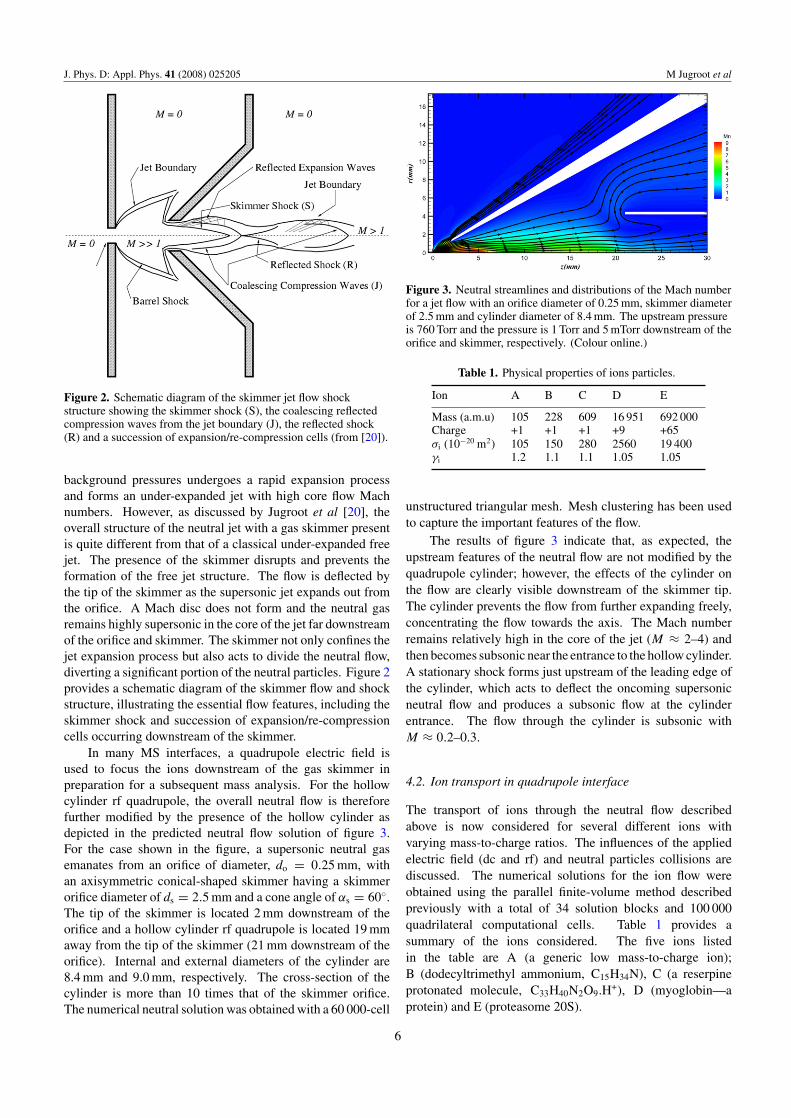
Figure 2. Schematic diagram of the skimmer jet flow shockstructure showing the skimmer shock (S), the coalescing reflectedcompression waves from the jet boundary (J), the reflected shock(R) and a succession of expansion/re-compression cells (from [20]).
background pressures undergoes a rapid expansion processand forms an under-expanded jet with high core flow Machnumbers. However, as discussed by Jugroot et al [20], theoverall structure of the neutral jet with a gas skimmer presentis quite different from that of a classical under-expanded freejet. The presence of the skimmer disrupts and prevents theformation of the free jet structure. The flow is deflected bythe tip of the skimmer as the supersonic jet expands out fromthe orifice. A Mach disc does not form and the neutral gasremains highly supersonic in the core of the jet far downstreamof the orifice and skimmer. The skimmer not only confines thejet expansion process but also acts to divide the neutral flow,diverting a significant portion of the neutral particles. Figure 2provides a schematic diagram of the skimmer flow and shockstructure, illustrating the essential flow features, including theskimmer shock and succession of expansion/re-compressioncells occurring downstream of the skimmer.
In many MS interfaces, a quadrupole electric field isused to focus the ions downstream of the gas skimmer inpreparation for a subsequent mass analysis. For the hollowcylinder rf quadrupole, the overall neutral flow is thereforefurther modified by the presence of the hollow cylinder asdepicted in the predicted neutral flow solution of figure 3.For the case shown in the figure, a supersonic neutral gasemanates from an orifice of diameter, do = 0.25 mm, withan axisymmetric conical-shaped skimmer having a skimmerorifice diameter of ds = 2.5 mm and a cone angle of αs = 60◦.The tip of the skimmer is located 2 mm downstream of theorifice and a hollow cylinder rf quadrupole is located 19 mmaway from the tip of the skimmer (21 mm downstream of theorifice). Internal and external diameters of the cylinder are8.4 mm and 9.0 mm, respectively. The cross-section of thecylinder is more than 10 times that of the skimmer orifice.The numerical neutral solution was obtained with a 60 000-cell
Figure 3. Neutral streamlines and distributions of the Mach numberfor a jet flow with an orifice diameter of 0.25 mm, skimmer diameterof 2.5 mm and cylinder diameter of 8.4 mm. The upstream pressureis 760 Torr and the pressure is 1 Torr and 5 mTorr downstream of theorifice and skimmer, respectively. (Colour online.)
Table 1. Physical properties of ions particles.
Ion A B C D E
Mass (a.m.u) 105 228 609 16 951 692 000Charge +1 +1 +1 +9 +65σi (10−20 m2) 105 150 280 2560 19 400γi 1.2 1.1 1.1 1.05 1.05
unstructured triangular mesh. Mesh clustering has been usedto capture the important features of the flow.
The results of figure 3 indicate that, as expected, theupstream features of the neutral flow are not modified by thequadrupole cylinder; however, the effects of the cylinder onthe flow are clearly visible downstream of the skimmer tip.The cylinder prevents the flow from further expanding freely,concentrating the flow towards the axis. The Mach numberremains relatively high in the core of the jet (M ≈ 2–4) andthen becomes subsonic near the entrance to the hollow cylinder.A stationary shock forms just upstream of the leading edge ofthe cylinder, which acts to deflect the oncoming supersonicneutral flow and produces a subsonic flow at the cylinderentrance. The flow through the cylinder is subsonic withM ≈ 0.2–0.3.
4.2. Ion transport in quadrupole interface
The transport of ions through the neutral flow describedabove is now considered for several different ions withvarying mass-to-charge ratios. The influences of the appliedelectric field (dc and rf) and neutral particles collisions arediscussed. The numerical solutions for the ion flow wereobtained using the parallel finite-volume method describedpreviously with a total of 34 solution blocks and 100 000quadrilateral computational cells. Table 1 provides asummary of the ions considered. The five ions listedin the table are A (a generic low mass-to-charge ion);B (dodecyltrimethyl ammonium, C15H34N), C (a reserpineprotonated molecule, C33H40N2O9.H+), D (myoglobin—aprotein) and E (proteasome 20S).
6

J. Phys. D: Appl. Phys. 41 (2008) 025205 M Jugroot et al
Figure 4. Computed ion particle (black) and neutral gas (purple) streamlines and distributions of the ion velocity (m s−1) for under-expandedskimmer jet flows. Results in upper and lower panels show ion B for an applied dc potential (without rf quadrupole) and a combined dc/rfpotential (quadrupole with q = 0.2), respectively. The potential on the orifice is 80 V and the skimmer is grounded. (Colour online.)
4.2.1. Hollow cylindrical quadrupole. Figure 4 depictsthe trajectory of ion B and highlights the differencesbetween an applied dc potential (orifice-skimmer only) anda superimposed dc/rf potential for the quadrupole interface,as shown in the upper and lower panels. The effect of the rfpotential within the cylinder is clearly evident as the ions arefocused towards the axis of symmetry. The rf cylinder is infact very efficient in focusing the ions. The mass flux of ionsthrough the quadrupole is about 37% higher than that of themass flux through the equivalent cross-section in the skimmer-only case.
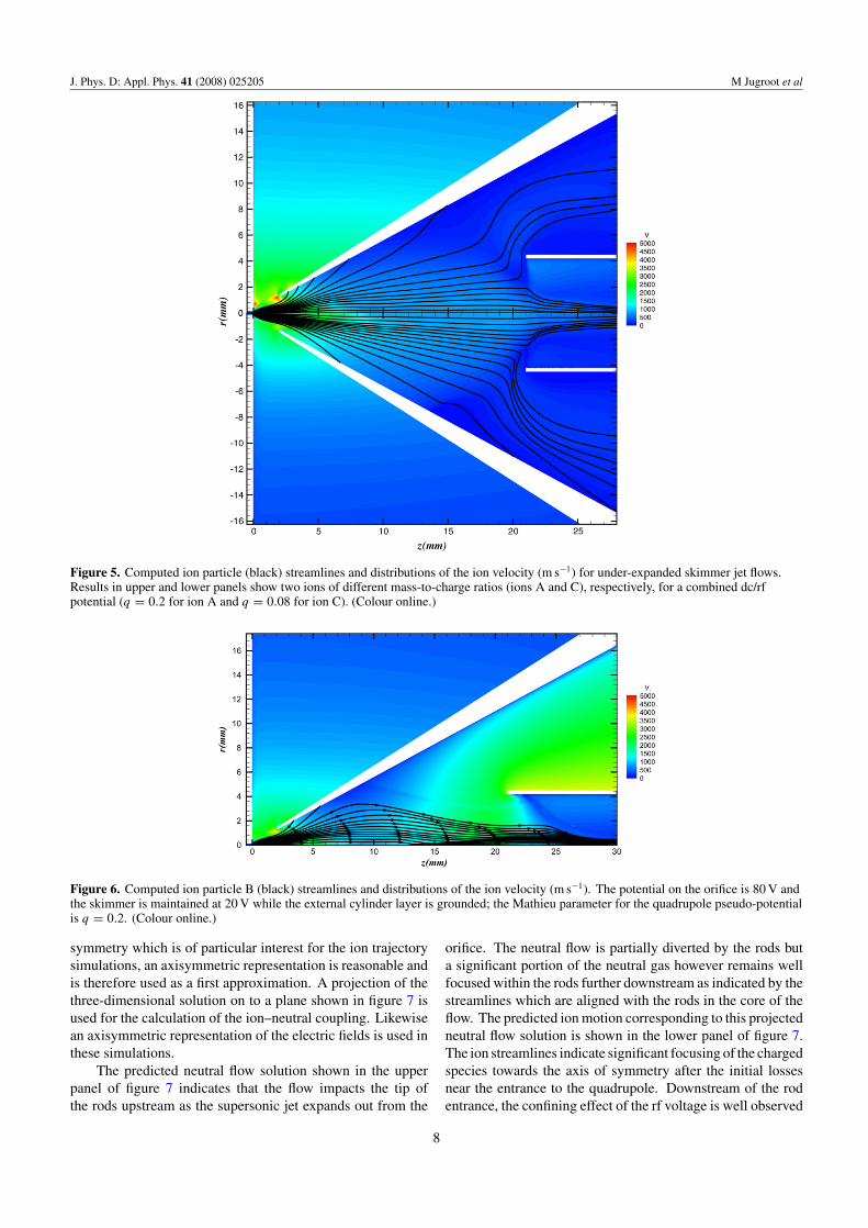
Figure 5 compares the trajectories of ions A and C inthe quadrupole interface as a result of the dc-rf superimposedfield. For the results shown in the figure, the quadrupolepseudo-potential is the same for both ions with q = 0.2 forion A and q = 0.08 for ion C. In general, the same globalbehaviour is observed for all the ions investigated. At theexit of the orifice, the ions follow the neutrals, but as theyapproach the skimmer regions, the ion trajectories clearlydeviate from those of the neutrals due to the high electricfield at the skimmer tip. Depending on the ion mass andcharge, the ions exhibit a clear tendency to follow the divergingelectric field lines and are strongly accelerated by the electricfield. Joule heating and drag forces also lead to elevated iontemperatures in this region. Beyond the skimmer tip region,where the magnitude of the electric field gradually diminishes,all ions tend to be again governed by the neutral flow. Finally,
the imposed pseudo-potential of the rf quadrupole produces astrong focusing of the ions towards the axis of symmetry. Infact, the rf field appears to be very efficient in confining theions as depicted in figures 4 and 5.
Further optimization of the ion transmission efficiencyis possible by tailoring the applied electric fields. Thisis demonstrated by the numerical results of figure 6 whereenhanced focusing is achieved by applying a dc potentialbetween the skimmer and the cylinder. The modified electricfield lines redirect the ions towards the axis and remain focuseddownstream.
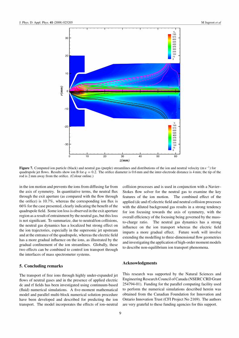
4.2.2. Traditional four-rod quadrupole. For comparisonpurposes, the traditional four-rod quadrupole has also beeninvestigated. This interface consists of an orifice and a setof four rods downstream of the orifice. The atmosphericconditions are maintained in the reservoir upstream of theorifice and the background pressure in the quadrupole chamberis maintained at 2.3 Torr. The pressure is 5 mTorr at the exitaperture (into the next chamber) for the cases described herein.The predicted neutral gas and ion flow solutions are shownin figure 7 for this case. The figure depicts the solutionin a vertical passing through the axis of symmetry for thequadrupole and lying in between the rods. The rods arenot visible in the figure. Note that the neutral solutions forthe four-rod quadrupole are inherently three-dimensional innature; however, in the core region of the flow near the axis of
7
J. Phys. D: Appl. Phys. 41 (2008) 025205 M Jugroot et al
Figure 5. Computed ion particle (black) streamlines and distributions of the ion velocity (m s−1) for under-expanded skimmer jet flows.Results in upper and lower panels show two ions of different mass-to-charge ratios (ions A and C), respectively, for a combined dc/rfpotential (q = 0.2 for ion A and q = 0.08 for ion C). (Colour online.)
Figure 6. Computed ion particle B (black) streamlines and distributions of the ion velocity (m s−1). The potential on the orifice is 80 V andthe skimmer is maintained at 20 V while the external cylinder layer is grounded; the Mathieu parameter for the quadrupole pseudo-potentialis q = 0.2. (Colour online.)
symmetry which is of particular interest for the ion trajectorysimulations, an axisymmetric representation is reasonable andis therefore used as a first approximation. A projection of thethree-dimensional solution on to a plane shown in figure 7 isused for the calculation of the ion–neutral coupling. Likewisean axisymmetric representation of the electric fields is used inthese simulations.
The predicted neutral flow solution shown in the upperpanel of figure 7 indicates that the flow impacts the tip ofthe rods upstream as the supersonic jet expands out from the
orifice. The neutral flow is partially diverted by the rods buta significant portion of the neutral gas however remains wellfocused within the rods further downstream as indicated by thestreamlines which are aligned with the rods in the core of theflow. The predicted ion motion corresponding to this projectedneutral flow solution is shown in the lower panel of figure 7.The ion streamlines indicate significant focusing of the chargedspecies towards the axis of symmetry after the initial lossesnear the entrance to the quadrupole. Downstream of the rodentrance, the confining effect of the rf voltage is well observed
8
J. Phys. D: Appl. Phys. 41 (2008) 025205 M Jugroot et al
Figure 7. Computed ion particle (black) and neutral gas (purple) streamlines and distributions of the ion and neutral velocity (m s−1) forquadrupole jet flows. Results show ion B for q = 0.2. The orifice diameter is 0.6 mm and the inter-electrode distance is 4 mm; the tip of therod is 2 mm away from the orifice. (Colour online.)
in the ion motion and prevents the ions from diffusing far fromthe axis of symmetry. In quantitative terms, the neutral fluxthrough the exit aperture (as compared with the flow throughthe orifice) is 10.7%, whereas the corresponding ion flux is66% for the case presented, clearly indicating the benefit of thequadrupole field. Some ion loss is observed in the exit apertureregion as a result of entrainment by the neutral gas, but this lossis not significant. To summarize, due to neutral/ion collisions,the neutral gas dynamics has a localized but strong effect onthe ion trajectories, especially in the supersonic jet upstreamand at the entrance of the quadrupole, whereas the electric fieldhas a more gradual influence on the ions, as illustrated by thegradual confinement of the ion streamlines. Globally, thesetwo effects can be combined to control ion transport throughthe interfaces of mass spectrometer systems.
5. Concluding remarks
The transport of free ions through highly under-expanded jetflows of neutral gases and in the presence of applied electricdc and rf fields has been investigated using continuum-based(fluid) numerical simulations. A five-moment mathematicalmodel and parallel multi-block numerical solution procedurehave been developed and described for predicting the iontransport. The model incorporates the effects of ion–neutral
collision processes and is used in conjunction with a Navier–Stokes flow solver for the neutral gas to examine the keyfeatures of the ion motion. The combined effect of theapplied (dc and rf) electric field and neutral collision processeswith the diluted background gas results in a strong tendencyfor ion focusing towards the axis of symmetry, with theoverall efficiency of the focusing being governed by the mass-to-charge ratio. The neutral gas dynamics has a stronginfluence on the ion transport whereas the electric fieldimparts a more gradual effect. Future work will involveextending the modelling to three-dimensional flow geometriesand investigating the application of high-order moment modelsto describe non-equilibrium ion transport phenomena.
Acknowledgments
This research was supported by the Natural Sciences andEngineering Research Council of Canada (NSERC CRD Grant254794-01). Funding for the parallel computing facility usedto perform the numerical simulations described herein wasobtained from the Canadian Foundation for Innovation andOntario Innovation Trust (CFI Project No 2169). The authorsare very grateful to these funding agencies for this support.
9

J. Phys. D: Appl. Phys. 41 (2008) 025205 M Jugroot et al
References
[1] Groves J and Wadley H 1997 Composites B 28 57–69[2] Martinez-Sanchez M and Pollard J E 1998 J. Propulsion
Power 14 688–99[3] Jugroot M and Harvey J K 2001 Aeronaut. J. 105 613–18[4] Jugroot M, Bayle P, Yousfi M and Eichwald O 1999
J. Phys. D: Appl. Phys. 32 106–20[5] Cinalli M and Keppens R 2006 J. Phys. D: Appl. Phys.
39 4589–600[6] Pal S, Dey S and Miebach 2007 J. Phys. D: Appl. Phys.
40 3128–36[7] Cravens T E 1997 Physics of Solar System Plasmas
(Cambridge, UK: Cambridge University Press)[8] Thomas R 2001 Spectroscopy 16 28–37[9] Furuya H, Fujimaki S, Kambara S, Suzuki S, Hashimoto Y,
Okazaki S, Wada A, Beech I, Sunner J and Hiraoka K 2005Rapid Commun. Mass Spectrom. 19 2433–42
[10] Glish G L and Vachet R W 2003 Nature Rev. Drug Discovery2 140–50
[11] Prestage J 1999 NASA Tech. Brief NPO-20011[12] Jugroot M, Groth C P T, Thomson B, Baranov V and
Collings B A 2003 Paper AIAA-2003-4210[13] Jugroot M, Groth C P T, Thomson B, Baranov V and
Collings B A 2004 J. Phys. D: Appl. Phys. 37 550–9[14] Burgers J M 1969 Flow Equations for Composite Gases
(New York: Academic)[15] Barakat A R and Schunk R W 1982 Plasma Phys. 24 389–418[16] Gombosi T I and Rasmussen C E 1991 J. Geophys. Res. 96
7759–78[17] Gombosi T I 1994 Gaskinetic Theory (Cambridge: Cambridge
University Press)
[18] Bhatnagar P L, Gross E P and Krook M 1954 Phys. Rev.94 511–25
[19] Clemmer D E and Jarrold M F 1997 J. Mass Spectrom.32 577–92
[20] Jugroot M, Groth C P T, Thomson B, Baranov V andCollings B A 2004 J. Phys. D: Appl. Phys. 37 1289–300
[21] Barth T J 1993 Paper AIAA-93-0668[22] Venkatakrishnan V 1993 Paper AIAA-93-0880[23] Roe P L 1981 J. Comput. Phys. 43 357–72[24] Linde T J 1998 PhD Thesis University of Michigan[25] Toro E F, Spruce M and Speares W 1994 Shock Waves 4 25–34[26] Gottlieb J J and Groth C P T 1988 J. Comput. Phys. 78 437–58[27] van Leer B, Tai C H and Powell K G 1989 Paper
AIAA-89-1933-CP[28] Groth C P T, Zeeuw D L D, Powell K G, Gombosi T I and
Stout Q F 1999 Paper AIAA-99-3273[29] Groth C P T, De Zeeuw D L, Gombosi T I and Powell K G
2000 J. Geophys. Res. 105 25053–78[30] Peroomian O, Chakravarthy S and Goldberg U C 1997 Paper
AIAA-97-0724[31] Peroomian O, Chakravarthy S and Goldberg U C 1998 Paper
AIAA-98-0116[32] Gropp W, Lusk E and Skjellum A 1999 Using MPI
(Cambridge, MA: MIT Press)[33] Karypis G and Kumar V 1998 J. Parallel Distrib. Comput.
48 96–129[34] Paul W 1990 Rev. Mod. Phys. 62 531–40[35] Leibfried D, Blatt R, Monroe C and Wineland D 2003 Rev.
Mod. Phys. 75 281–324[36] Tolmachev A V, Chernushevish I V, Dodonov A F and
Standing K G 1997 Nucl. Instrum. Methods Phys. Res. B124 112–19
10