Embed Size (px)
Citation preview
€33 W
W 0 -=I- O W
- 1-
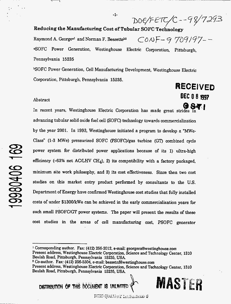
Reducing the Manufacturing Cost of Tubular SOFC Technology
Raymond A. Georgeo' and Norman F. 13essetteb2 co /u F- 9 707/ 7 7- - aSOFC Power Generation, Westinghouse Electric Corporation, Pittsburgh,
Pennsylvania 15235
bSOFC Power Generation, Cell Manufacturing Development, Westinghouse Electric
Corporation, Pittsburgh, Pennsylvania 15235. REC*EIVED
Abstract @ m-1 In recent years, Westinghouse Electric Corporation has made great strides in
advancing tubular solid oxide fuel cell (SOFC) technology towards commercialization
by the year 2001. In 1993, Westinghouse initiated a program to develop a " m e -
Class" (1-3 MWe) pressurized SOFC (PSOFC)/gas turbine (GP combined cycle
power system for distributed power applications because of its 1) ultra-high
efficiency (-63% net A C L W CHq), 2) its compatibility with a factory packaged,
minimum site work philosophy, and 3) its cost effectiveness. Since then two cost
studies on this market entry product performed by consultants to the U.S.
Department of Energy have conhned Westinghouse cost studies that fully installed
costs of under $1300/kWe can be achieved in the early commercialization years for
such small PSOFCIGT power systems. The paper will present the results of these
cost studies in the areas of cell manufacturing cost, PSOFC generator
1 Corresponding author. Fax: (412) 256-2012, e-mail: [email protected] Present address, Westinghouse Electric Corporation, Science and Technology Center, 1310 Beulah Road, Pittsburgh, Pennsylvania 15235, USA 2 Co-author. Fax: (412) 256-5504, e-mail: [email protected] Present address, Westinghouse Electric Corporation, Science and Technology Center, 1310 Beulah Road, Pittsburgh, Pennsylvania 15235, USA
n
DISCLAIMER
This report was prepared as an account of work sponsored by an agency of the United States Government. Neither the United States Government nor any agency thereof, nor any of their employees, makes any warranty, express or implied, or assumes any legal liability or responsibility for the accuracy, completeness, or use- fulness of any information, apparatus, product, or process disclosed, or represents that its use would not infringe privately owned rights. Reference herein to any spe- cific commercial product, process, or service by trade name, trademark, manufac- turer, or otherwise docs not necessarily constitute or imply its endorsement, recom- mendation, or favoring by the United States Government or any agency thereof. The views and opinions of authors expressed herein do not necessarily state or reflect those of the United States Government or any agency thereof.
-2-
manufacturing cost, balance-of-plant (BOP) cost, and system installation cost. In
addition, cost of electricity calculations will be presented. .
Keywords: SOFC; SOFCIGT; Manufacturing Cost
1. Introduction
Over the past 10 years the Westinghouse SOFC development team has made major
progress towards reducing SOFC manufacturing costs ($/kWe). This paper describes
the important technology breakthroughs, presents the results of a cost study of a
3 MWe pressurized SOFC (PSOFC)/gas turbine (GT) power system performed in
1996 by Westinghouse and two consultants (A. D. Little and Spencer Management)
to the U.S. Department of Energy and updated by Westinghouse in 1997, and
compares the cost of electricity (COE) of such a system with that of the most
advanced small (e5 W e ) gas turbine generator currently under development.
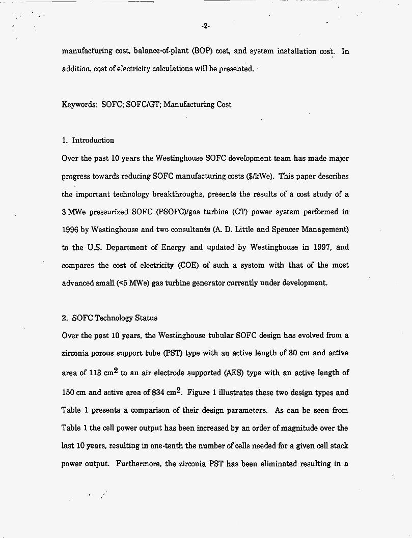
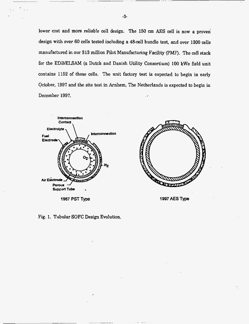
2. SOFC Technology Status
Over the past 10 years, the Westinghouse tubular SOFC design has evolved from a
zirconia porous support tube (PST) type with an active length of 30 cm and active
area of 113 cm2 to an air electrode supported (AES) type with an active length of
150 cm and active area of 834 cm2* Figure 1 illustrates these two design types and
Table 1 presents a comparison of their design parameters. As can be seen from
Table 1 the cell power output has been increased by an order of magnitude over the
last 10 years, resulting in one-tenth the number of cells needed'for a given cell stack
power output. Furthermore, the zirconia PST has been eliminated resulting in a
-3-
lower cost and more reliable cell design. The 150 cm AES cell is now a proven
design with over 60 cells tested including a 48-cell bundle test, and over 1300 cells
manufactured in our $13 million Pilot Manufacturing Facility (PMF). The cell stack
for the EDBIELSAM (a Dutch and Danish Utility Consortium) 100 kWe field unit
contains 1152 of these cells. The unit factory test is expected to begin in early
October, 1997 and the site test in Amhem, The Netherlands is expected to begin in
December 1997.
contact
Electrolyte, \ Intenonm&*on
“2
Porous -.J SUPPO~TUM i
1987 PST Type 1997 AES Type
Fig. 1. Tubular SOFC Design Evolution.
-4-
I 1987PSTType I 1997 AES Type Cell OD (cm) 1.52 2.23 Cell active length (cm) 30 150
- ~
Cell total length (cm) 42 168 Cell active area (cm2) 113 834 PST ID/OD (cm) 0.89/1.29 N. A./N.A.*
~~~ ~-
AE ID/OD (cm) 1.2911.49 1.7612.20 IC lengtldwidth (cm) 3011.1 150/1.1 IC thickness (pm) 40 100
r
EL thickness (pm) 40 40
FE thickness (pm) 100 100 Max. power @ 1 atm (watts) 20 2 10
*Not applicable
Table 1. Tubular SOFC Design Parameter Comparison
The cell scale-up to commercial size has been completed, and the emphasis is
now on materials cost reduction, development of low cost manufacturing processes,
and supplier development. Since the air electrode tube constitutes 92% of the
weight of the finished cell, the material cost reduction program is focused on the air
electrode precursor materials (i.e., the raw materials which are used for synthesizing
doped LaMnO3). In particular, the focus is on quslifving lower purity precursor
materials, which will reduce the air electrode precursor materials cost in large
volume from $25/cell to $S/cell. Concerning the development of low cost
manufacturing processes, the focus over the last 5 years has been the substitution of
lower cost ceramic processes, such as plasma spray and sintering, for
-5-
electrochemical vapor deposition (EVD). Five years ago, all three thin film layers
(interconnection, electrolyte and fuel electrode) were deposited by EVD. Since 1992
the interconnection has been deposited by plasma spray in production (over 2500
cells produced with plasma sprayed interconnections). In addition, over 20 cells
have been made in the laboratory with sintered fuel electrodes, and Westinghouse
expects to initiate production of sintered fuel electrode cells in the PMF by June,
1998. It is anticipated that the first production line in the Commercial
Manufacturing Facility (CMF) will consist of the following thin film deposition
processes: plasma spray for the interconnection, EVD for the electrolyte and slurry
dippingkintering for the fuel electrode. Finally, for the last 2 years, Westinghouse
has been developing strategic partners for the supply of ceramic materials and
components. Praxair Surface Technologies, for example, is collaborating with
Westinghouse to produce 1) doped LaCr03 powder for plasma spraying the
interconnection, 2) doped LaMnO3 powder for air electrode tubing making, and 3)
sintered air electrode tubes.
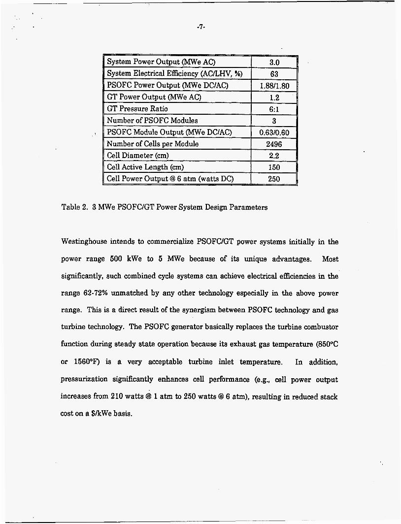
3. 3 MNe PSOFCIGT Power System Description
For the purpose of the cost study performed by Westinghouse, A. D. Little, and
Spencer Management, Westinghouse performed a conceptual design of a 3 MWe
PSOFCIGT power system. Table 2 presents the top level system design parameters
and Figure 2 presents the system schematic. As shown in Figure 2, the turbine
compressor provides the pressurized air to the PSOFC generator (in this case three
600 kWe modules). Pressurized natural gas is also delivered to the PSOFC
generator where it fist undergoes reformation to Hp and CO within the cell stack,
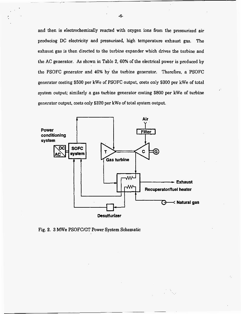
and then is electrochemically reacted with oxygen ions from the pressurized air
producing DC electricity and pressurized, high temperature exhaust gas. The
exhaust gas is then directed to the turbine expander which drives the turbine and
the AC generator. As shown in Table 2, 60% of the electrical power is produced by
c - Exhaust
the PSOFC generator and 40% by the turbine generator. Therefore, a PSOFC
generator costing $500 per kWe of PSOFC output, costs only $300 per kWe of total
system output; similarly a gas turbine generator costing $800 per kWe of turbine
generator output, costs only $320 per kWe of total system output,
Fig. 2. 3 MWe PSOFCIGT Power System Schematic
. .
-7-
PSOFC Module Output (MWe DCIAC) Number of Cells per Module
0.6 310.6 0 2496
, Cell Diameter (cm) 2.2 Cell Active Length (cm) 150 Cell Power Output @ 6 atm (watts DC) 250
Table 2. 3 Mwe PSOFCIGT Power System Design Parameters
Westinghouse intends to commercialize PSOFCIGT power systems initially in the
power range 500 kWe to 5 MWe because of its unique advantages. Most
sigdicantly, such combined cycle systems can achieve electrical efficiencies in the
range 62.72% unmatched by any other technology especially in the above power
range. This is a direct result of the synergism between PSOFC technology and gas
turbine technology. The PSOFC generator basically replaces the turbine combustor
function during steady state operation because its exhaust gas temperature (850°C
or 1560°F) is a very acceptable turbine inlet temperature. In addition,
pressurization sigdicantly enhances cell performance (e.g., cell power output
increases from 210 watts @ 1 atm to 250 watts @ 6 atm), resulting in reduced stack
cost on a $&We basis.
-8-
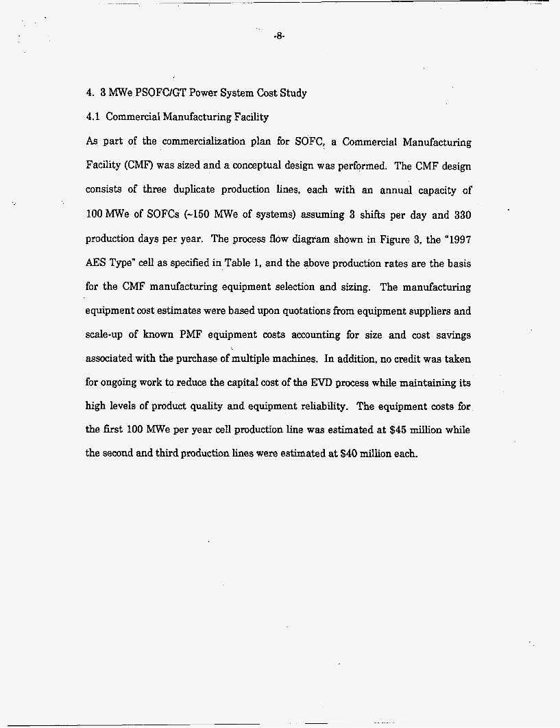
4. 3 MWe PSOFCIGT Power System Cost Study
4.1 Commercial Manufacturing Facility
As part of the commercialization plan for SOFC, a Commercial Manufacturing
Facility (CMF) was sized and a conceptual design was performed. The CMF design
consists of three duplicate production lines, each with an annual capacity of
1OOMWe of SOFCs (-150 MWe of systems) assuming 3 shifts per day and 330
production days per year. The process flow diagram shown in Figure 3, the “1997
AES Type” cell as specified in Table 1, and the above production rates are the basis
for the CMF manufacturing equipment selection and sizing. The manufacturing
equipment cost estimates were based upon quotations from equipment suppliers and
scale-up of known PMF equipment costs accounting for size and cost savings
associated with the purchase of multiple machines. In addition, no credit was taken
for ongoing work to reduce the capital cost of the EVD process while maintaining its
high levels of product quality and equipment reliability. The equipment costs for
the first 100 MWe per year cell production line was estimated at $45 million while
the second and third production lines were estimated at $40 million each.
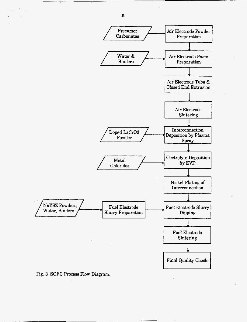
-9-
Water & , Binders
I Precursor Air Electrode Powder Carbonates Preparation
Air Electrode Paste Preparation
) , Doped LaCr03
Powder
Air Electrode
Interconnection Deposition by Plasma
Spray
, Fuel Electrode , Fuel Electrode Slurry Slurry Preparation Dipping
I I Final Quality Check
Fig. 3 SOFC Process Flow Diagram.
- 10-
In order to determine the building size, a layout of the three cell production lines
was performed. In addition, space was allocated for SOFC module assembly and
system assembly assuming the output of the CMF to be skid-mounted, fully
packaged 3 MWe PSOFC/GT Power Systems requiring a minimum of site
installation. The cost of the manufacturing building and property was estimated
assuming both new construction and the purchase of an existing building. It was
concluded that utilizing an existing building was advantageous to minimize the
initial capital investment for the CMF as well as take advantage of an abundance of
vacant sites. Preliminary estimates require approximately 250,000 fk2 of 35 ft high
bay space per production line of 150 MWe per year of 3 W e power systems for a
total floor space of 750,000 ft2. The building purchase price for an existing building
of this size was estimated at $45 per ft2 or $35 million.
For the purpose of this cost study, a capital investment of $80 million ($45 million
for the first production line and $35 million for the building) was used for an annual
production rate of 150 MWe of 3 Mwe PSOFCIGT power systems. The
manufacturing equipment was depreciated over 10 years and the building was
depreciated over 20 years. These annual costs were included as part of the cell
manufacturing cost discussed in Section 4.3.
In 1998, Westinghouse plans to perform a detailed design and cost estimate of the
CMF as input to the decision making process in 1999 concerning construction of the
CMF. Assuming a positive decision to proceed with the construction of the CMF,
plant commissioning should occur in the year 2001.
-11-
4.2 Cell Manufacturing Process Description
4.2.1 Air Electrode Fabrication
Air electrodes, which form the basic building block of the tubular SOFC, are
manufactured from a mixture of base carbonates which form the doped LaMn03
giving the cell its excellent durability, thermal cycle ability, and electrical
performance. The base carbonates are first weighed and ball milled and
subsequently calcined to provide a homogeneous material. The calcined material is
then crushed and milled to provide the correct particle size distribution. This
material is then mixed with water and binders to form a paste capable of being
extruded. The paste is first extruded into a hemispherical mold to form the closed
end of the tube, the mold removed, and the extrusion continues in a smooth fashion
allowing for the formation of the remaining cylindrical section with a finished length
of 181 cm. Through this technique the closed end and cylinder remain a
homogeneous material sigdcantly improving quality and yield of the finished
product. The extruded tube section is then sintered a t approximately 1500°C to
form the tubular building block.
4.2.2 Interconnection Deposition by Plasma Spray
The interconnection is deposited on the air electrode tube using an atmospheric
plasma spray process to obtain a gas tight positive (+) contact stable in a dual
atmosphere. The interconnection material is a doped LaCr03 made from base
carbonates much in the same manner as the air electrode powder. The powder is fed
to a plasma spray gun where in combination with hydrogen and electricity, a plasma
- 12-
is formed which is sprayed onto the air electrode tube through a 150 cm by 1.1 cm
window defined by a metal mask. The cell is held vertically while the gun traverses
axially. Application requires approximately 4 minutes and lends itself well to
automation through the use of multiple guns. This material and manufacturing
process have been successfully demonstrated in two 25 kWe generators of 576 cells
each, which operated for greater than 5,000 and 13,000 hours, respectively. No
significant voltage degradation was observed in either generator and the tests were
ended because all the contractual commitments were fully satisfied.
4.2.3 Electrolyte Deposition by Electrochemical Vapor Deposition
To deposit a perfectly gas tight uniform layer over greater than 1000 cm2 with an
exceptionally high yield, the Westinghouse design has relied on the electrochemical
vapor deposition (Em) process. At temperatures near 12OO0C and vacuum
pressures near 1 mmHg, anhydrous mixtures of yttrium trichloride and zirconium
tetrachloride are sublimed and passed over the exterior of the air electrode-
interconnection assembly. Oxgen is provided to the tube interior. The chlorides
react chemically and electrochemically with the oxygen passing through the tube
wall to form the zirconium oxide layer on the tube exterior. Since the film growth is
partially governed by the mixed conductivity of the material and electrical path
resistance, thin portions grow faster than thicker portions resulting in a uniform
film of nominally 40 pm in thickness.
. .
-13-
4.2.4 Application of a Nickel Contact by Electroplating
The other advantage of the Westinghouse tubular SOFC besides its seal-less design
is the metallic connections made between cells through the use of nickel felt or
nickel wool. This electrical integration is made possible by nickel electroplating of
the interconnection to provide the metallic surface for nickel felt bonding. Cells are
placed in a nickel sulfamate bath containing a sacrificial nickel anode while a
cathode is inserted into the cell tube. Since yttria stabilized zirconia (YSZ) is an
insulator at room temperature, only the doped L a 0 3 material will carry electricity
thereby defining its own mask. Current is passed through the system resulting in a
5-10 pm thick nickel layer on the interconnection. Both capital and material cost
are small. A reliable contact has been achieved on all generators used in the field to
date.
4.2.5 Fuel Electrode Application by Slurry Dipping
The he1 electrode, or anode, of the cell is deposited through a slurry dip process. A
mixture of nickel and yttria stabilized zirconia (YSZ) powders having the proper
thermal expansion match with the rest of the cell components is first blended and
the mixed with water and binders in the proper ratio to achieve a highly viscous
slurry. The material is then circulated through a number of vertical 2 inch
diameter, 70 inch long acrylic tubes with a diaphragm pump to a void slurry
stratification. Cells from electrolyte EVD have a vinyl tape placed over the
interconnection and are dipped in the slurry containers. Cells are then extracted at
a slow rate allowing for flash drying to avoid slurry sagging which results in
-14-
excessive thickness non-uniformities adversely impacting cell performance and
structural integrity. Through this process a uniform 100 pm thick layer can be
maintained with a standard deviation of less than 10 pm. The vinyl tape is
subsequently removed and the cell is prepared for the sinter step. This slurry
application process has been utilized in the previous and the present Westinghouse
manufacturing facility for both 50 and 150 cm active length cells with high
reliability, high yield, and low material waste. With only ball mills and small
pumps, the capital cost component and plant footprint requirement are minimal.
4.2.6 Fuel Electrode Sintering
To complete the fuel electrode application step the cell is sintered at approximately
1300°C in a dual atmosphere furnace for two hours. During this process air is
delivered to the cell interior while a reducing atmosphere is provided on the fuel
electrode side to avoid nickel oxidation. In a high volume facility a continuous
furnace system would be utilized to decrease capital and operational costs. Fuel
electrodes sintered in this manner have been shown to have the same or better
performance then the EVD applied fuel electrode and have been thermal cycled firom
operating temperature (lOOO°C) to room temperature over 30 times with no
deleterious impact.
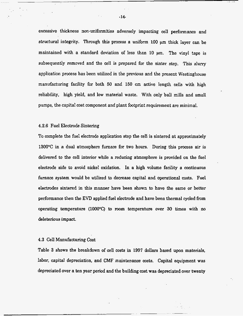
4.3 Cell Manufacturing Cost
Table 3 shows the breakdown of cell costs in 1997 dollars based upon materials,
labor, capital depreciation, and CMF maintenance costs. Capital equipment was
depreciated over a ten year period and the building cost was depreciated over twenty
. -
. .
-15-
years. Even though the building was sized and costed for 3 production lines or
450MWelyear of system capacity, the entire depreciation for the building was
included in the cell cost for the fust production line (under the capital column of
Table 3), which burdened the cell cost by an extra $3/cell. The material costs are
based upon supplier quotations for large volumes equivalent to 100 MWe of SOFCs
per year. Labor and maintenance costs are based upon extrapolations from our
PMF experience.
Table 3. Breakdown of Cell Cost.
As seen in Table 3 the cell cost in large volume is only $53.81 or $224 per kWe of
SOFC output (= $53.81/cell x 3 x 2496 cells + 1800 kWe). On a total system output
basis this reduces to $134/kW (= 224 x .SO). As expected, the electrolyte is the
highest cost layer. Interestingly, the fuel electrode has the second highest cost at
slightly less than half the cost of electrolyte. A simple comparison of the electrolyte
and fuel electrode costs shows that the elimination of an EVD step in favor of a
sintering step reduces the cell cost by approximately $14 ( the four cost categories of
EVD are comparable whether for electrolyte or fuel electrode). Therefore, changing
- 16-
the electrolyte deposition process from EVD to sintering would save $14/cell if a
sintered electrolyte could provide the electrical performance and process yield of an
electrolyte EVD process.
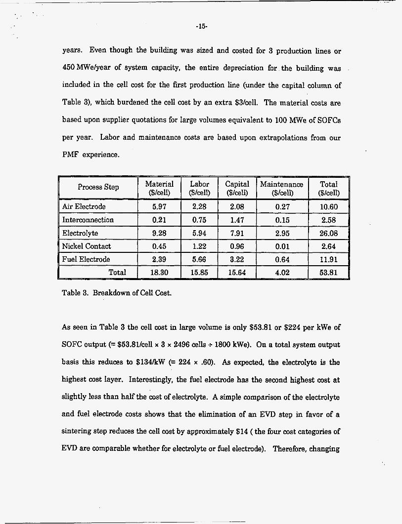
4.4 PSOFC Generator Manufacturing Cost
For the purpose of this cost study, a conceptual design was performed of a 1.8 MWe
PSOFC generator, consisting of three, 600 kWe modules contained within a common
pressure vessel as illustrated in Figu're 4. Each module consists of 2496 SOFCs
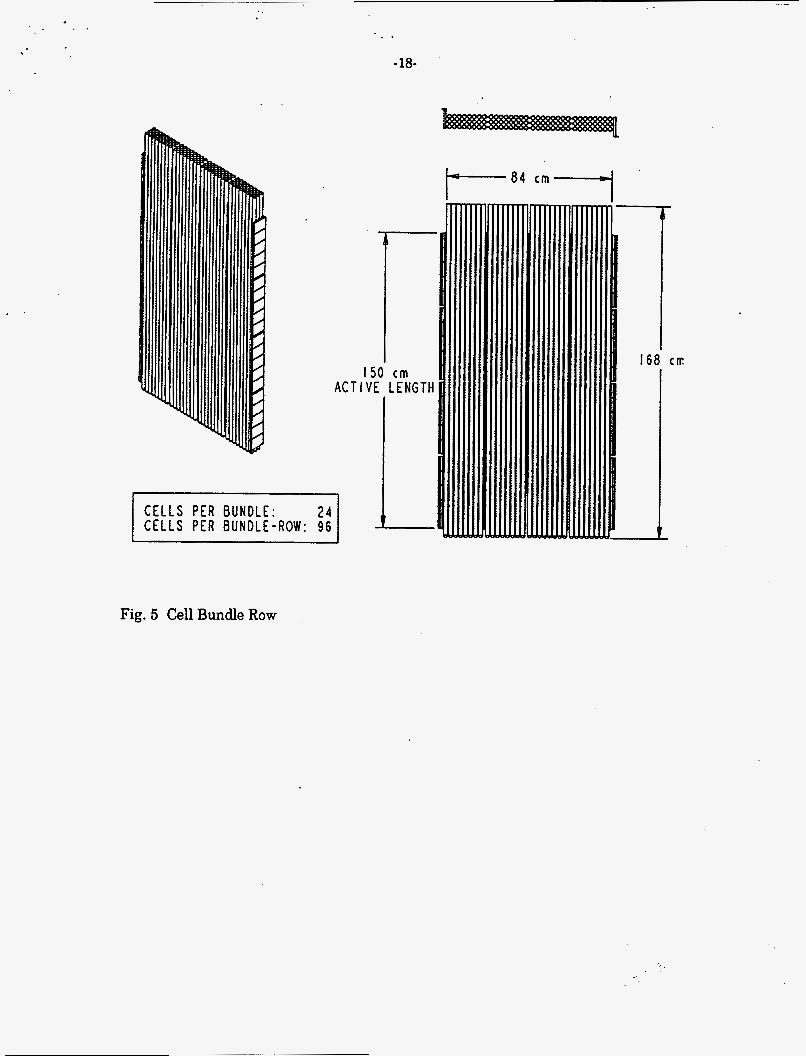
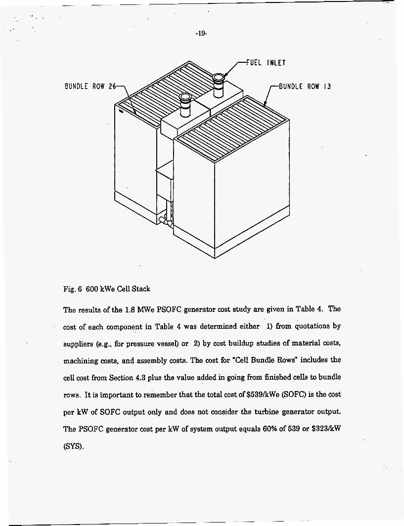
arranged in 26 bundle rows, each consisting of 96 cells, as shown in Figures 5 and 6,
16 air plenum assemblies which include 2496 alumina air feed tubes, 24 stack
reformer sections which are sandwiched between bundle rows, 1 spent fuel
recirculation loop and pre-reformer, insulation, instrumentation, and 1 stack
container. Finished cells are assembled into bundle rows with the use of nickel felts
and nickel paste. The stack is then assembled by arranging the bundle rows and
stack reformer sections in an alternating pattern on a support board assembly which
also distributes the reformed fuel to each cell. The spent fuel recirculation loop and
the air plenum assemblies are then installed. The stack is then surrounded by
insulation and inserted into the stack container completing the 600 kWe module
assembly. Three of these modules are inserted into the pressure vessel as shown in
Figure 4 forming the 1.8 MWe PSOFC generator.
. -_
. .
-17-
Fig. 4 1.8 MWe PSOFC Generator
. .
-18-
C E L L S PER BUNDLE: C E L L S PER BUNDLE-ROW: 9 6 L
150 cm A C T I V E LENGTH
-84 cm-
168 cm
Fig. 5 Cell Bundle Row
- 19-
BUNDLE ROW .E ROW 13
Fig. 6 600 kWe Cell Stack
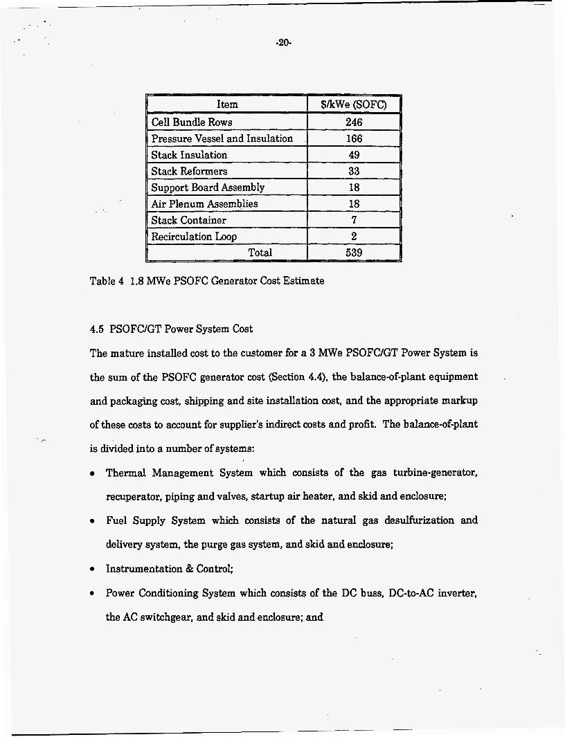
The results of the 1.8 MWe PSOFC generator cost study are given in Table 4. The
cost of each component in Table 4 was determined either 1) from quotations by
suppliers (e.g., for pressure vessel) or 2) by cost buildup studies of material costs,
machining costs, and assembly costs. The cost for "Cell Bundle Rows" includes the
cell cost from Section 4.3 plus the value added in going from finished cells to bundle
rows. It is important to remember that the total cost of $539/kWe (SOFC) is the cost
per kW of SOFC output only and does not consider the turbine generator output.
The PSOFC generator cost per kW of system output equals 60% of 539 or $323/kW
(SYS).
-20-
I Item I Cell Bundle Rows 246 I Pressure Vessel and Insulation 166 Stack Insulation 49
~ ~- ~
Stack Reformers 33 Support Board Assembly 18
Table 4 1.8 MWe PSOFC Generator Cost Estimate
4.5 PSOFCIGT Power System Cost
The mature installed cost to the customer for a 3 W e PSOFCIGT Power System is
the sum of the PSOFC generator cost (Section 4.4), the balance-of-plant equipment
and packaging cost, shipping and site installation cost, and the appropriate markup
of these costs to account for supplier3 indirect costs and profit. The balance-of-plant
is divided into a number of systems:
Thermal Management System which consists of the gas turbine-generator,
recuperator, piping and valves, startup air heater, and skid and enclosure;
Fuel Supply System which consists of the natural gas desulfurization and
delivery system, the purge gas system, and skid and enclosure;
Instrumentation 8z Control;
Power Conditioning System which consists of the DC buss, DC-to-AC inverter,
the AC switchgear, and skid and enclosure; and
-21-
0 Electrical Distribution System which distributes electrical power to equipment
within the system (e.g., valve actuators, instruments, control computer, etc.)
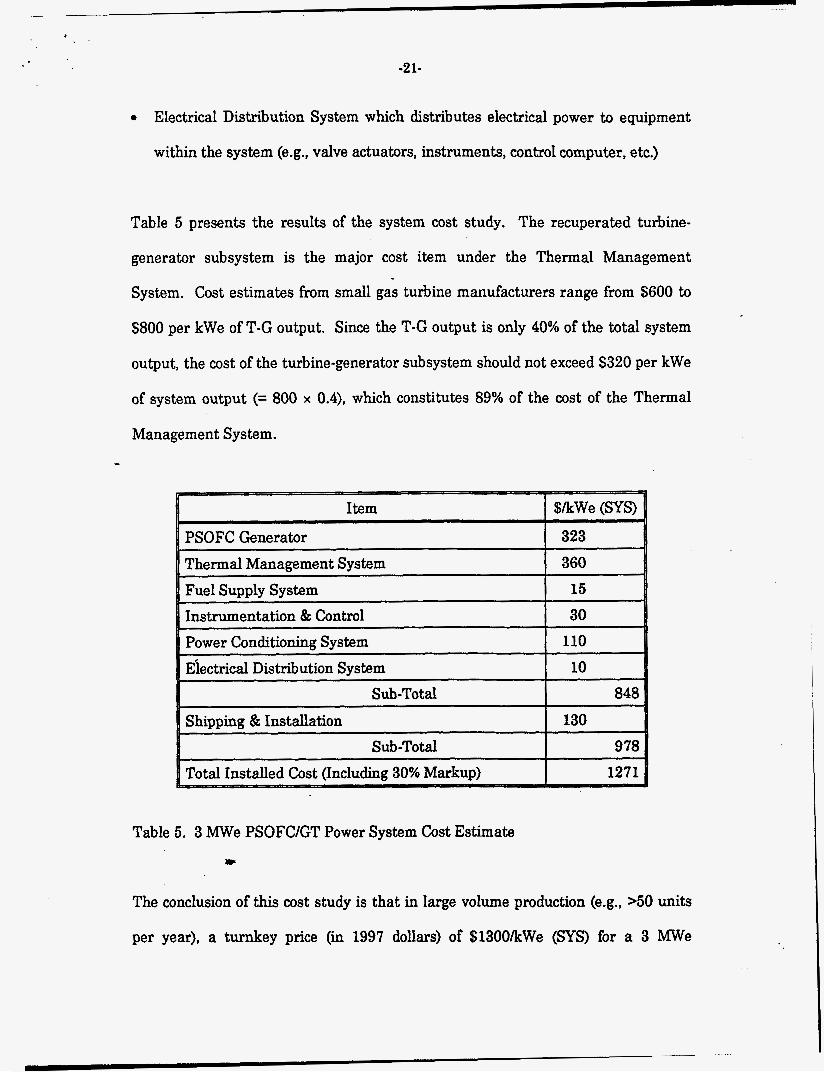
Table 5 presents the results of the system cost study. The recuperated turbine-
generator subsystem is the major cost item under the Thermal Management
System. Cost estimates from small gas turbine manufacturers range from $600 to
$800 per kWe of T-G output. Since the T-G output is only 40% of the total system
output, the cost of the turbine-generator subsystem should not exceed $320 per kWe
of system output (= 800 x 0.4), which constitutes 89% of the cost of the Thermal
Management System.
Table 5. 3 MWe PSOFCIGT Power System Cost Estimate ;p’
The conclusion of this cost study is that in large volume production ( e g , >50 units
per year), a turnkey price (in 1997 dollars) of $1300/kWe (SYS) for a 3 MWe
. .
i . -
-22-
PSOFCIGT Power System should be readily achievable with attractive margins
remaining for the supplier.
5. Cost of Electricity Analysis
A cost of electricity (COE) analysis was performed comparing the COE of the 3 MWe
PSOFCIGT Power System with that of the most advanced small gas turbine
generator system. The latter system called the Advanced Turbine System or ATS is
currently under development in the United States and has a target turbine inlet
temperature of 2200°F. This ATS has a power output of about 4 MWe, a projected
electrical efficiency of 42%, and a projected total installed cost of about $800/kWe.
For comparison, the PSOFCIGT system described herein has a power output of
3 MWe, a projected electrical efficiency of 63%, and a projected total installed cost of
$1300/kWe. The major COE assumptions are 1) a 15% capital charge rate,
2) $3/MBTU natural gas cost, a plant capacity factor of 85% and 4) replacement of
SOFC bundle rows every 10 years at a cost in 1997 dollars of $250/kWe (SOFC).
The COE analyses resulted in the same COE (within 1%) for both systems
(4.8 centslkWh). The relatively high capital cost of the PSOFCIGT system is o&et
by its relatively low fuel cost. For conservatism, a high capital charge rate and low
natural gas cost were used in this analysis, which favor the economics of the ATS.
Under expected conditions of lower capital charge rates and/or higher natural gas
costs, the PSOFCIGT system would have a lower COE relative to the 4 MWe ATS.
6. Summary and Conclusions
The PSOFCIGT Power System is the most fuel efficient electrical power generation
system ever conceived with efficiencies in the range 62-72% depending upon the
-23-
ratio of SOFC-to-GT power output, and the type of GT selected. The broad
application of this technology will significantly extend the use of our fossil fuel
resources. For a 3 MWe PSOFCIGT Power System with an electrical efficiency of
63%, a total installed cost of $1300/kWe should be readily achievable after 2 to 3
years of commercial production. The projected cost of electricity (COE) for this
machine compares very favorably with the projected COE for the most advanced
small gas turbine system (ATS), which is also under development. In addition, the
PSOFC/GT power system offers lower CO2 emissions by virtue of its higher
efficiency (33% less C02 emitted per kWh compared to the small ATS), NO,
emissions of about 1 ppm compared to >lo ppm for the ATS, and no SO, emissions
since sulfur compounds are removed from the natural gas.
Report Number
Publ. Date (11)
DOE