Embed Size (px)
Citation preview

European Co-operation in the Field of Scientific and
Technical Research
COST 354
COST Secretariat
25 April 2007
COST 354 Performance Indicators for Road Pavements
WP 2 "Selection and assessment of individual performance indicators"
Report
COST354/WP2_Report_30052008

Performance indicators for Road Pavements COST 354 WP 2: "Individual Performance Indicators"
WP2 Report Page 2 of 166 April 2007
Selection and assessment of individual
performance indicators
Report
INTRODUCTION ............................................................................................................7
SECTION 1: LONGITUDINAL EVENNESS ...............................................................10
1.1 LONGITUDINAL EVENNESS INDICATORS FROM THE COST 354 DATABASE ................................................................................................10 1.1.1 General information ........................................................................12 1.1.2 Standard practice or application for research.................................15 1.1.3 Standardization...............................................................................16 1.1.4 Measuring principle ........................................................................17 1.1.5 Quality assurance...........................................................................18
1.2 EVALUATION OF THE MOST SUITABLE INDIVIDUAL PERFORMANCE INDICATORS .............................................................................................19 1.2.1 TP International Roughness Index (IRI) .........................................19 1.2.2 Technical Parameters Wavelength, Evenness and Longitudinal
Profile Variance ..............................................................................25
1.3 SELECTION OF THE PROPOSED INDIVIDUAL PERFORMANCE INDICATOR ...............................................................................................28
1.4 PROTOCOLS AND TEST METHODS FOR MEASURING THE PROPOSED INDIVIDUAL INDICATOR.....................................................29 1.4.1 Measurement equipment................................................................29 1.4.2 Calculation algorithms and data processing...................................30
1.5 ASSESSMENT OF THE TRANSFORMATION FUNCTIONS....................31 1.5.1 General information ........................................................................31 1.5.2 Classification for technical parameter International Roughness Index
(IRI).................................................................................................32 1.5.3 Assessment of transformation functions for IRI..............................38 1.5.4 Technical Parameters Wavelength, Evenness and Longitudinal
Profile Variance ..............................................................................40
1.6 REFERENCES...........................................................................................42
SECTION 2: TRANSVERSE EVENNESS..................................................................43
2.1 TRANSVERSE EVENNESS INDICATORS FROM THE COST 354 DATABASE ................................................................................................43 2.1.1 General information ........................................................................44 2.1.2 Category of performance indicator .................................................47 2.1.3 Field of application – distribution by road network..........................48 2.1.4 Distribution by Level of Application.................................................49 2.1.5 Distribution by Pavement Type.......................................................49 2.1.6 Distribution by Type of Application .................................................50 2.1.7 Standardization...............................................................................51 2.1.8 Measuring principle ........................................................................53 2.1.9 Quality assurance...........................................................................56

Performance indicators for Road Pavements COST 354 WP 2: "Individual Performance Indicators"
WP2 Report Page 3 of 166 April 2007
2.1.10 Measuring interval ..........................................................................56
2.2 COMPLEMENTARY INFORMATION DERIVED FROM LITERATURE ....57 2.2.1 Draft European Standards..............................................................57 2.2.2 FILTER – Theoretical Study of Indices – Technical Note 2000/02.58 2.2.3 FHWA Report Characterization of Transverse Profiles, FHWA-RD-
01-024, April 2001. .........................................................................59 2.2.4 Potential additional transverse evenness indicators.......................60
2.3 EVALUATION OF THE MOST SUITABLE INDIVIDUAL PERFORMANCE INDICATORS .............................................................................................61 2.3.1 Technical parameter Rut Depth......................................................61 2.3.2 Technical parameters Cross-fall, Water Height and Edge
Deformation ....................................................................................66
2.4 SELECTION OF THE PROPOSED INDIVIDUAL PERFORMANCE INDICATOR ...............................................................................................68
2.5 PROTOCOLS AND TEST METHODS FOR MEASURING THE PROPOSED INDIVIDUAL INDICATORS ..................................................70 2.5.1 Measurement equipment................................................................70 2.5.2 Calculation algorithms and data processing...................................71 2.5.3 Accuracy of measurements ............................................................73
2.6 ASSESSMENT OF THE TRANSFORMATION FUNCTIONS....................76
2.7 CORRELATION BETWEEN THE SELECTED INDICATOR AND OTHER USED INDICATORS ..................................................................................81
2.8 REFERENCES...........................................................................................82
SECTION 3: MACRO TEXTURE ...............................................................................83
3.1 TEXTURE INDICATORS FROM THE COST 354 DATABASE .................83 3.1.1 General information ........................................................................84 3.1.2 Category of performance indicator .................................................86 3.1.3 Field of application – distribution by road network..........................86 3.1.4 Distribution by Level of Application.................................................87 3.1.5 Distribution by Pavement Type.......................................................87 3.1.6 Distribution by Type of Application .................................................88 3.1.7 Standardization...............................................................................89 3.1.8 Measuring principle ........................................................................89
3.2 COMPLEMENTARY INFORMATION DERIVED FROM LITERATURE ....90
3.3 EVALUATION AND SELECTION OF THE MOST USED INDIVIDUAL PERFORMANCE INDICATORS; ...............................................................90
3.4 PROTOCOLS AND TEST METHODS FOR MEASURING THE PROPOSED INDIVIDUAL INDICATOR.....................................................92
3.5 ASSESSMENT OF THE TRANSFORMATION FUNCTIONS....................92
3.6 CORRELATION BETWEEN THE SELECTED INDICATOR AND OTHER USED INDICATORS ..................................................................................95
3.7 REFERENCES...........................................................................................96
SECTION 4: FRICTION..............................................................................................97
4.1 SKID RESISTANCE INDICATORS FROM THE COST 354 DATABASE..97 4.1.1 General information ........................................................................98

Performance indicators for Road Pavements COST 354 WP 2: "Individual Performance Indicators"
WP2 Report Page 4 of 166 April 2007
4.1.2 Category of performance indicator .................................................99 4.1.3 Field of application – distribution by road network..........................99 4.1.4 Distribution by level of application ................................................102 4.1.5 Distribution by Pavement Type.....................................................102 4.1.6 Distribution by Type of Application ...............................................104 4.1.7 Standardization.............................................................................105 4.1.8 Measuring principle ......................................................................105
4.2 CORRELATIONS BETWEEN TRANSFORMATION FUNCTIONS AND LIMITS IN USE IN THE DIFFERENT COUNTRIES AND FOR THE DIFFERENT PARAMETERS USED ........................................................109 4.2.1 Correlations between transformation functions ............................109 4.2.2 Limits ............................................................................................112
4.3 EVALUATION OF THE MOST USED INDIVIDUAL PERFORMANCE INDICATORS ...........................................................................................125
4.4 SELECTION OF THE PROPOSED INDIVIDUAL PERFORMANCE INDICATOR .............................................................................................128
4.5 PROTOCOLS AND TEST METHODS FOR MEASURING THE PROPOSED INDIVIDUAL INDICATORS ................................................130
4.6 ASSESSMENT OF THE TRANSFORMATION FUNCTIONS..................130
4.7 CORRELATION BETWEEN THE SELECTED INDICATOR AND THE USED INDICATORS ................................................................................135
4.8 REFERENCES.........................................................................................137
SECTION 5: NOISE .................................................................................................138
5.1 NOISE POLLUTION INDICATORS FROM THE COST 354 DATABASE138 5.1.1 General information ......................................................................138 5.1.2 Category of the PI.........................................................................139 5.1.3 Field of application – distribution by road network........................140 5.1.4 Distribution by Level of Application...............................................140 5.1.5 Distribution by Pavement Type.....................................................141 5.1.6 Type of application .......................................................................141 5.1.7 Standardization.............................................................................142 5.1.8 Measuring principle ......................................................................142
5.2 COMPLEMENTARY INFORMATION DERIVED FROM LITERATURE ..143 5.2.1 HARMONOISE .............................................................................143 5.2.2 Silvia .............................................................................................143 5.2.3 Environmental Noise Directive 2002/49/EC .................................144
5.3 SELECTION OF THE PROPSED INDIVIDUAL PERFORMANCE INDICATOR .............................................................................................144
5.4 REFERENCES.........................................................................................145
SECTION 6: AIR POLLUTION .................................................................................146
6.1 AIR POLLUTION INDICATORS FROM THE COST 354 DATABASE.....146 6.1.1 General information ......................................................................146 6.1.2 Category of performance indicator ...............................................147 6.1.3 Field of application – distribution by road network........................147 6.1.4 Distribution by Level of Application...............................................148 6.1.5 Distribution by Pavement type......................................................148 6.1.6 Type of application .......................................................................148

Performance indicators for Road Pavements COST 354 WP 2: "Individual Performance Indicators"
WP2 Report Page 5 of 166 April 2007
6.1.7 Standardization.............................................................................149 6.1.8 Measuring principle ......................................................................149
6.2 EVALUATION OF THE MOST SUITABLE PERFORMANCE INDICATORS.................................................................................................................150 6.2.1 Name of the indices and transformation function .........................150 6.2.2 Limits ............................................................................................150
6.3 SELECTION OF THE PROPOSED INDIVIDUAL PERFORMANCE INDICATOR .............................................................................................150
6.4 PROTOCOLS AND TEST METHODS FOR MEASURING THE PROPOSED INDIVIDUAL INDICATORS. ...............................................151
6.5 ASSESSMENT OF THE TRANSFORMATION FUNCTIONS..................151
SECTION 7: BEARING CAPACITY .........................................................................152
7.1 BEARING CAPACITY INDICATORS FROM THE COST 354 DATABASE.................................................................................................................152 7.1.1 General information ......................................................................152 7.1.2 Category of performance indicator ...............................................153 7.1.3 Field of application – distribution by road network........................154 7.1.4 Distribution by Level of Application...............................................155 7.1.5 Distribution by Pavement Type.....................................................155 7.1.6 Distribution by Type of Application ...............................................156 7.1.7 Standardisation.............................................................................156 7.1.8 Measuring principle ......................................................................158
7.2 COMPLEMENTARY INFORMATION DERIVED FROM LITERATURE ..159
7.3 SELECTION OF THE PROPOSED INDIVIDUAL PERFORMANCE INDICATOR .............................................................................................160
7.4 PROTOCOLS AND TEST METHODS FOR MEASURING THE PROPOSED INDIVIDUAL INDICATOR...................................................161
7.5 ASSESSMENT OF THE TRANSFORMATION FUNCTIONS..................161
7.6 REFERENCES.........................................................................................163
SECTION 8: SUMMARY AND CONCLUSIONS ......................................................164
8.1 SYNTHESIS OF SELECTED TP, PERFORMANCE INDICES AND TRANSFER FUNCTIONS........................................................................164
8.2 FUTURE PERSPECTIVES AND RESEARCH NEEDS ...........................165
SECTION 9: GLOSSARY OF TERMS .....................................................................166

Performance indicators for Road Pavements COST 354 WP 2: "Individual Performance Indicators"
WP2 Report Page 6 of 166 April 2007
Authors of the report: Introduction Francesca La Torre (Italy) Section 1: Longitudinal Evenness Julijana Jamnik (Slovenia) Section 2: Transverse Evenness Goran Mladenovic (Serbia) Section 3: Macrotexture Charles Lykke Hansen (Denmark) &
Leif Sjogren (Sweden) Section 4: Friction Marta Alonso (Spain) Section 5: Noise Jan Doorduijn (The Netherlands) Section 6: Air Pollution Jan Doorduijn (The Netherlands) Section 7: Bearing Capacity Francesca La Torre (Italy) Section 8: Summary and Conclusions Francesca La Torre (Italy) Section 9: Glossary of Terms Radu Andrei (Romania) Editing by Stuart Brittain (UK) Members of WG2: Mate SRSEN Croatia Charles LYKKE HANSEN Denmark Tristan LORINO France Sebastien WASNER France Andreas LOIZOS Greece Christina PLATI Greece Robert KAROLY Hungary Francesca LA TORRE (WG Leader) Italy Jan DOORDUIJN Netherlands Antonio PINELO Portugal Radu ANDREI Romania Goran MLADENOVIC Serbia Julijana JAMNIK Slovenia Marta ALONSO Spain Leif SJÖGREN Sweden Katherine PETROS U.S.A.

Performance indicators for Road Pavements COST 354 WP 2: "Individual Performance Indicators"
WP2 Report Page 7 of 166 April 2007
INTRODUCTION
COST Action 354 - Performance Indicators for Road Pavements started in April 2004. The main objective of the Action is the definition of uniform European performance indicators and indices for road pavements taking the needs of road users and road operators into account. A quantitative assessment of individual performance indicators provides guidance regarding present and future needs in road pavement design and maintenance at both the national and the European levels. By specifying limits and acceptance values for individual performance indicators minimum standards can be laid down for both projected and existing road pavements. Performance indicators should be defined for different types of pavement structures and road categories. The specification of performance criteria from the perspectives of both road users and road operators is a key prerequisite for the efficient design, construction and maintenance of road pavements. Particularly the increasing use of life-cycle analyses as a basis for the selection of road pavements and the decision of whether or not to implement a systematic road maintenance scheme calls for an exact definition of the goals to be achieved and/or the performance criteria to be satisfied. The extent to which goals are reached or performance criteria satisfied can be quantified by calculating special indices characterizing the road pavement, which in turn permits an assessment of the efficiency of certain approaches from both a commercial and a macro-economic standpoint. For a Europe-wide harmonization of standards to be met by road pavements it therefore appears useful and appropriate to specify pavement characteristics in terms of uniform “performance indicators” for different road categories (motorways, national roads, local roads, etc.). It is envisaged that the application of such uniform indices will allow the specification of minimum European standards for road pavements. In addition, it would also be feasible and useful to filter out those areas of the European road network where more investment is needed to attain such minimum standards (depending on the road category). Performance indicators for road pavements could, however, also be used as inputs to pavement management systems (PMS), for calculating maintenance needs and thus to provide objective arguments for the need of reinvestment in road pavements. Based on previous results of COST Actions and European research projects the definition and assessment of individual representative performance indicators and the development of combined performance indices will be conducted. A separate COST Action offers an excellent framework to bring together the existing knowledge from a large number of COST countries and USA. This knowledge is gathered from national road administrations, including experts from research laboratories and universities. The work program to be carried out under this COST Action is subdivided into five work packages, each producing one of the five deliverables. This report describes the work carried out in Work Package 2 “Selection and assessment of individual performance indicators”. The aim of this WP was to identify a set of “Performance Indices” to represent in a unitless scale the following Performance Indicators: - Longitudinal evenness; - Transverse evenness;

Performance indicators for Road Pavements COST 354 WP 2: "Individual Performance Indicators"
WP2 Report Page 8 of 166 April 2007
- Macrotexture; - Friction; - Noise; - Air Pollution; - Bearing Capacity. Cracking was initially considered as a single performance indicator but it was then decided to consider this as a combined performance indicator and it is therefore tackled by WG3 of COST 354 action. Within the COST 354 action a “Performance Index” has been defined as a dimensionless figure in a 0 to 5 scale with 0 representing a pavement in very good conditions and 5 a very poor one, with respect to a specific pavement condition property. A Performance index can usually be derived from a “Technical Parameter” that is a physical characteristic of the road pavement condition obtained from measurements by a device or collected by other forms of investigation (e.g. rut depth, friction value, etc.) In this context a “Performance Indicator” for road pavement is the superior term of a technical road pavement characteristic, that indicates the condition of it (e.g. transverse evenness, skid resistance, etc.). A performance indicator can be defined in the form of technical parameters (as a rule dimensional) and/or in form of dimensionless indices. The planned activities for WG2 were: - Select suitable performance indicators - Define target values and limits - Develop transformation functions from Technical Parameters to performance
indices - Provide a practical guide for the calculation of the performance index These have been performed mostly based on the results of the work of WG1 of this COST action using the data contained in the so-called COST-354 database. In some cases it was deemed necessary to integrate the data in the database with an additional literature review to obtain a Performance Index for a given indicator. The main aim of defining dimensionless Performance Indices is that they will then be combined into “Combined Performance Indices” in WP3 of this action and then into a “Global Performance Index” in WP4 of this same action. Given the wide variety of potential users of the COST 354 final procedure it was deemed necessary in WP2 to develop a procedure that could be applied at all different levels depending on the type of measurement and analysis approach already in place in the road authority applying the procedure. The different levels can be summarized as follows: - The user provides the value for the Technical Parameter identified as the “most
suitable” by WG2 and, by means of the transfer functions described in this report, derives a value for the dimensionless Performance Index;
- The user provides the value for the Technical Parameter identified as the “most suitable” by WG2 but applies a different transfer function to derive a value for the dimensionless Performance Index (always in the same 0 to 5 scale as above);
- The user provides the value for a different Technical Parameter and applies his own transfer function to derive a value for the dimensionless Performance Index (always in the same 0 to 5 scale as above);

Performance indicators for Road Pavements COST 354 WP 2: "Individual Performance Indicators"
WP2 Report Page 9 of 166 April 2007
- The user provides directly a value for the dimensionless Performance Index (always in the same 0 to 5 scale as above).
As far as the target values and limits are concerned, it was decided to analyse them and use them as a surrogate measure for defining transfer functions, these will therefore be described in this report. On the other hand, no target values or limit will be proposed as “reference” in this report as these strongly depend on the type of road and on the serviceability level that the road authority wants to achieve. This report is intended for use only within this Action and therefore it is effectively a snapshot in time of the individual and combined pavement performance indicators being used currently throughout Europe and USA. The number of countries included in the COST 354 Action is 24 (23 European + USA). For the purpose of this report only 22 out of the 24 countries were considered. This was because the information provided by Bulgaria and Romania was included in the database after version 2 (dated 15 October 2005), which served as the basis for the WG2 activities. Some minor adjustments to the data contained in version 2 of the database have been included in the report based on the comments of the WG2 members. All of these adjustments have been included in later revisions of the database. Some of the data from Croatia was rectified or integrated during the WG2 work and therefore could not be considered in the distribution analysis. In the tables the rectified figures are indicated with a note explaining the change as compared to the available database.

Performance indicators for Road Pavements COST 354 WP 2: "Individual Performance Indicators"
WP2 Report Page 10 of 166 April 2007
SECTION 1: LONGITUDINAL EVENNESS
1.1 LONGITUDINAL EVENNESS INDICATORS FROM THE COST 354 DATABASE
The number of countries included in the COST 354 Action is 22. All of the countries filled in the longitudinal evenness performance indicator group but the number of questionnaires analyzed is 24 because France and Belgium reported two each. An initial examination of the longitudinal evenness performance indicator group found some inconsistencies that needed to be sorted out before the analysis could begin. Two indicators were found which did not fit into this group, one detailing durability cracking and the other spalling of longitudinal and transverse joints (both on rigid pavements, taken with visual inspection). They were both excluded from further analyses regarding longitudinal evenness and moved into the groups Cracking and Joint Spalling Width, respectively. Analysing the database further it was found out that several answers from one country mean that in fact it goes for different measuring devices or different technical parameters and therefore it is correct that they are included in further analyses. The only exception is Czech Republic where two answers mean the same performance indicator and the only difference between them is the Field of Application (first for Motorways and Other Primary Roads and the second one for Secondary Roads and Other Roads), resulting in the difference only in threshold values and transformation functions of indices. Therefore they were merged. Table 1 shows the number of records analyzed. It doesn’t fit with the number of questionnaires. The reason is that Belgium, France, Germany and United Kingdom gave 3 answers and Spain and Sweden reported 2 answers. That means that the total number of records analyzed for longitudinal evenness performance indicator is 32. Furthermore answers from Bulgaria and Romania were received, but not included in the evaluation because they were received to late for the analysis.

Performance indicators for Road Pavements COST 354 WP 2: "Individual Performance Indicators"
WP2 Report Page 11 of 166 April 2007
Table 1: Number of countries, questionnaires and records referred to the longitudinal evenness performance indicator
TOTAL LONGITUDINAL EVENNESS COUNTRY Nº QUESTIONNAIRES Nº RECORDS
AUSTRIA (AT) 1 1
BELGIUM (BE) 2 3
CROATIA (HR) 1 1
CZECH REPUBLIC (CZ) 1 1
DENMARK (DK) 1 1
FINLAND (FI) 1 1
FRANCE (FR) 2 3
GERMANY (DE) 1 3
GREECE (EL) 1 1
HUNGARY (HU) 1 1
ITALY (IT) 1 1
NETHERLANDS (NL) 1 1
NORWAY (NO) 1 1
POLAND (PL) 1 1
PORTUGAL (PT) 1 1
SERBIA AND MONTENEGRO (CS) 1 1
SLOVENIA (SI) 1 1
SPAIN (ES) 1 2
SWEDEN (SE) 1 2
SWITZERLAND (CH) 1 1
UNITED KINGDOM (UK) 1 3
USA (US) 1 1
22 24 32

Performance indicators for Road Pavements COST 354 WP 2: "Individual Performance Indicators"
WP2 Report Page 12 of 166 April 2007
1.1.1 General information The longitudinal unevenness is the deviation of the longitudinal profile from a straight reference line in a wavelength range of 0.5m-50m. The range from 0.5 to 50m is the common range for roads. This limit can be extended to 100m for runways. Higher values don’t deal with unevenness but depend on road geometry. Different technical parameters for the longitudinal evenness performance indicator are used in individual countries. In the database TPs are described with: the name, the description, the abbreviation, the unit the measuring equipment and measuring principle. As the abbreviation is not the same for different countries, it is not included in this analysis. The situation is the same when considering the name and description. Therefore a new field, “Unified Name of TP” was added to the database by the WG 1 to be able to group the technical parameters. In the database there are 7 unified types of technical parameters describing longitudinal evenness: international roughness index wave length evenness longitudinal profile variance longitudinal profile spectral density standard deviation. It was very important to take into account the measuring principle and the device used to collect the data. Table 2 includes the unified name of the TP, the description, the unit, the equipment name and the measuring principle reported in the database.

Performance indicators for Road Pavements COST 354 WP 2: "Individual Performance Indicators"
WP2 Report Page 13 of 166 April 2007
Table 2: Description of longitudinal evenness technical parameters from the COST-354 database COUNTRY NAME NAME TP (Unified) DESCRIPTION UNIT EQUIPMENT NAME MEASURING PRINCIPLE
AUSTRIA (AT) Longitudinal evenness International roughness index International roughness index m/km RoadSTAR Laser
BELGIUM (BE) 1 Evenness Evenness Vlakheid other ARAN or Apl Accelerometer with laser BELGIUM (BE) 2 Longitudinal eveness Evenness Coefficient de planéité 2,5 other APL Accelerometer BELGIUM (BE) 3 Longitudinal evenness Evenness Coefficient de planéité 10 other APL Accelerometer
CROATIA (HR) Longitudinal evennes International roughness index International roughness index m/km Laser profil Laser (inertially referenced)
CZECH REPUBLIC (CZ) Longitudinal evenness Evenness severity of evenness - ARAN Laser
DENMARK (DK) Evenness International roughness index International Roughness Index m/km Profilograph Laser
FINLAND (FI) Longitudinal unevenness International roughness index Roughness mm/m RST Laser
FRANCE (FR) 1 Longitudinal profile Wave length Short wavelength - APL (SIRANO) Mechanical (inertially referenced) profilometer
FRANCE (FR) 2 Longitudinal profile Wave length Long wavelength APL (SIRANO) Mechanical (inertially referenced) profilometer
FRANCE (FR) 3 Longitudinal profile Wave length Medium wavelength - APL (SIRANO) Mechanical (inertially referenced) profilometer
GERMANY (DE) 1 General unevenness Spectral density Spectral Density cm3 Laser GERMANY (DE) 2 Periodical unevenness Wave length Wave length m Laser GERMANY (DE) 3 Single obstruction Wave length Wave length m Laser
GREECE (EL) Longitudinal evenness International roughness index Elevation m/km Laser Profiler Laser
HUNGARY (HU) Longitudinal unevenness International roughness index International Roughness Index m/km Road Survey Tester (RST) Laser
ITALY (IT) Longitudinal evenness International roughness index International Roughness Index m/km Profilometer Laser
NETHERLANDS (NL) Longitudinal evenness International roughness index IRI m/km ARAN Laser
NORWAY (NO) Longitudinal unevenness International roughness index IRI mm/m ALFRED Laser
POLAND (PL) Longitudinal evenness International roughness index International Roughness Index mm/m Greenwood Profilograph Laser
PORTUGAL (PT) Longitudinal unevenness International roughness index Longitudinal Unevenness m/km Laser profilometer Laser
SERBIA AND MONTENEGRO (CS) Longitudinal evenness International roughness
index Longitudinal Evenness m/km ROMDAS Bump Integrator Accelerometer
SLOVENIA (SI) Longitudinal evenness International roughness index IRI m/km Profilograph ZAG Accelerometer with differential
transformer
SPAIN (ES) 1 Longitudinal evenness International roughness index Roughness longitudinal profile m/km Dipstick Walking profiler

Performance indicators for Road Pavements COST 354 WP 2: "Individual Performance Indicators"
WP2 Report Page 14 of 166 April 2007
COUNTRY NAME NAME TP (Unified) DESCRIPTION UNIT EQUIPMENT NAME MEASURING PRINCIPLE
SPAIN (ES) 2 Longitudinal evenness International roughness index Roughness longitudinal profile m/km Laser profilometers Laser
SWEDEN (SE 1) Longitudinal unevenness International roughness index IRI mm/m Laser RST Laser
SWEDEN (SE) 2 Longitudinal unevenness Longitudinal profile Longitudinal profile mm Laser RST Laser SWITZERLAND (CH) Longitudinal evenness Standard deviation Standard deviation ‰ UNITED KINGDOM (UK) 1 Ride Quality (3m) Longitudinal profile variance 3m Longitudinal Profile Variance other Road Assessment Vehicle (RAV) Laser
UNITED KINGDOM (UK) 2 Ride Quality (10m) Longitudinal profile variance 10m Longitudinal Profile Variance other Road Assessment Vehicle (RAV) Laser
UNITED KINGDOM (UK) 3 Ride Quality (30m) Longitudinal profile variance 30m Longitudinal Profile Variance other Road Assessment Vehicle (RAV) Laser
USA (US) Smoothness International roughness index International Roughness Index inch/mi ARAN, ICC profiler …etc. Laser

Performance indicators for Road Pavements COST 354 WP 2: "Individual Performance Indicators"
WP2 Report Page 15 of 166 April 2007
In most of the cases with data available, the technical parameter measured is International Roughness Index IRI (17 cases of 32 total answers). In 5 records the technical parameter is Wavelength (from 2 questionnaires), in 4 records (3 are from the same questionnaire) the technical parameter is Evenness and in 3 records Longitudinal Profile Variance (all from 1 questionnaire). There are also single records for technical parameters Spectral Density, Longitudinal Profile and Standard Deviation. The results are shown in Figure 1.
Figure 1: Technical parameters for longitudinal evenness performance
indicator Given the fact that the majority or the responders use the IRI, some of the detailed analysis of the COST-354 database responses will have specific reference to IRI (see section 1.2.1). This is because analysing all the data together could lead to erroneous conclusions on the actual use of the specific selected index. In the following paragraphs the more “general” issues (standard practice or research, standardization etc) will be analysed with reference to all the different technical parameters included in the database.
1.1.2 Standard practice or application for research Figure 2 shows the distribution of answers for standard practice and practice for research for technical parameters of longitudinal evenness.

Performance indicators for Road Pavements COST 354 WP 2: "Individual Performance Indicators"
WP2 Report Page 16 of 166 April 2007
Figure 2: Number of answers for standard practice and application for research
for technical parameters of longitudinal evenness Longitudinal evenness measurements are a standard practice in the majority of countries.
1.1.3 Standardization The first question included in the chapter of data collection in the COST 354 database, is whether the technical parameter is measured according to a Standard. The answers obtained are shown in Figure 3.

Performance indicators for Road Pavements COST 354 WP 2: "Individual Performance Indicators"
WP2 Report Page 17 of 166 April 2007
Figure 3: Number of answers for used standard for technical parameters of
longitudinal evenness The most common way of measuring technical parameters is following a national standard. Only 3 countries stated ISO or CEN standards.
1.1.4 Measuring principle There are four groups of measuring principles in the database for assessing the longitudinal evenness performance indicator: laser, accelerometer, mechanical (inertial referenced) single wheel trailer, walking profiler Dipstick. The records included in the COST 354 database about the measuring principle for longitudinal evenness performance indicators are shown in Figure 4.

Performance indicators for Road Pavements COST 354 WP 2: "Individual Performance Indicators"
WP2 Report Page 18 of 166 April 2007
Figure 4: Number of answers for measuring principle for technical parameters
of longitudinal evenness From the answers it can be concluded that lasers are mainly used for measuring the longitudinal evenness performance indicators.
1.1.5 Quality assurance Figure 5 shows the distribution of answers for quality assurance for technical parameters of longitudinal evenness.
Figure 5: Number of answers for quality assurance for technical parameters of
longitudinal evenness

Performance indicators for Road Pavements COST 354 WP 2: "Individual Performance Indicators"
WP2 Report Page 19 of 166 April 2007
From the answers it can be concluded that quality assurance is taken into account for longitudinal evenness measurements.
1.2 EVALUATION OF THE MOST SUITABLE INDIVIDUAL PERFORMANCE INDICATORS
Four technical parameters from the COST 354 database were further analysed, namely International Roughness Index, Wavelength, Evenness and Longitudinal Profile Variance. From them, the International Roughness Index is most commonly used (in 53%) and is analysed in more detail.
1.2.1 TP International Roughness Index (IRI) Table 3 shows the information concerning the data collection for the technical parameter International Roughness Index (IRI). There are 17 answers in the database.

Performance indicators for Road Pavements COST 354 WP 2: "Individual Performance Indicators"
WP2 Report Page 20 of 166 April 2007
Table 3: Technical parameter “International Roughness Index” information from the database
COUNTRY STANDARD STANDARD NAME STANDARD
PRACTICE OR RESEARCH
TYPE OF INSPECTION COLLECTED DATA
OPERATING SPEED [Km/h]
SECTION LENGTH
[m] HOMOGENI-
ZATION INTERVAL
[years] QUALITY
ASSURANCE
AUSTRIA (AT) National Standard
RVS 11.066 - Teil VIII, Laengsebenheitsmessung mit dem System RoadSTAR
Standard Contactless Measurement Severity 60 50 yes 5 yes
CROATIA (HR) Technical Specification(*) OPCI Tehnicki OVJETI (OTU) (*) Standard &
Research Contactless
Measurement Extension 35-100 (*) 100 no 1 yes
DENMARK (DK) National Standard
Konstruktion og vedligehold af veje og stier, Hæfte 4, Vedligehold af færdselsarealet, Juni 2004.Comming CEN-standard #prEN 13036-5
Standard Contactless Measurement 20-100 1000 yes 1 yes
FINLAND (FI) ISO-Standard Standard Contactless Measurement Extension 80 100 no 1 yes
GREECE (EL) Technical Specification
Draft specification and contract documents in Greece Contactless
Measurement 40-100 10 no no
HUNGARY (HU) Technical Specification
ÚT 2-2.116/1998 RST-mérés és -értékelés (RST-measurement and evaluation)
Standard Contactless Measurement Extension 30-80 100 no 3 yes
ITALY (IT) Technical Specification
ASTM E 950-98; World Bank Technical Paper n° 45-46 Standard Contactless
Measurement Extension & Severity 70-80 20 yes 1 yes
NETHERLANDS (NL) Technical Specification
National Cooperative Highway Research Program (NCHRP). NCHRP Report 228.
Standard Contactless Measurement Severity 80 100 no 2 yes
NORWAY (NO) ISO-Standard ISO 13473 Contactless Measurement Severity 60-70 no yes
POLAND (PL) No Standard System Oceny Stanu Nawierzchni - Wytyczne stosowania, Załącznik B Standard Contactless
Measurement Severity 60 1000 no 1 yes
PORTUGAL (PT) No Standard Standard Contactless Measurement Severity 80 yes 4 yes
SERBIA AND MONTENEGRO (CS) No Standard ROMDAS Manuals and User's
Guides Standard Measurement Severity 32 25 yes 3 yes
SLOVENIA (SI) Technical Specification
TSC 06.610: 2003 Lastnosti voznih površin, Ravnost (Pavement surface properties, Evenness)
Research Contactless Measurement Severity 80 20 yes 5 yes
SPAIN (ES) 1 National Standard
NLT 331/98 Medida de la regularidad con perfilómetro pivotante de alta precisión
Measurement no yes
SPAIN (ES) 2 National Standard Research Contactless
Measurement Traffic no 3 yes
SWEDEN (SE 1) National Standard
RVS 11.066 - Teil VIII, Laengsebenheitsmessung mit dem System RoadSTAR
Standard Contactless Measurement Severity 60 50 yes 5 yes
USA (US) No Standard Standard Contactless Measurement Extension 100 no 1 yes
(*) information not in the COST database used for the analysis, obtained during the WG2 work. It is not included in the following distribution analyses.

Performance indicators for Road Pavements COST 354 WP 2: "Individual Performance Indicators"
WP2 Report Page 21 of 166 April 2007
1.2.1.1 Distribution of TP International Roughness Index (IRI) by the PI category In the Questionnaire there are four categories to choose from: Road Safety PI, Riding Comfort PI, Pavement Structure PI and Environmental PI. Figure 6 shows the distribution by the category of performance indicator for the TP IRI. No country included TP IRI into environmental PI.
Riding Comfort PI
10
Road Safety PI
Pavement Structure PI
0
0 6
0 0 1
Figure 6: Distribution by the category of PI for TP IRI All of the responders included IRI as a Riding comfort performance indicator, 94% as a Road safety and Riding comfort performance indicator and 35% as a Pavement structure, Road safety and Riding comfort performance indicator. 1.2.1.2 The distribution of TP International Roughness Index (IRI) by the road
category The question about the road network gave responders four possibilities: motorways, other primary roads, secondary roads and other roads. Figure 7 shows the distribution by road network for the TP IRI.
Performance indicators for Road Pavements COST 354 WP 2: "Individual Performance Indicators"
WP2 Report Page 22 of 166 April 2007
Motorways Primary Roads
Secondary Roads Other Roads
1 9
0
0 0 7 0
0
0 0
0
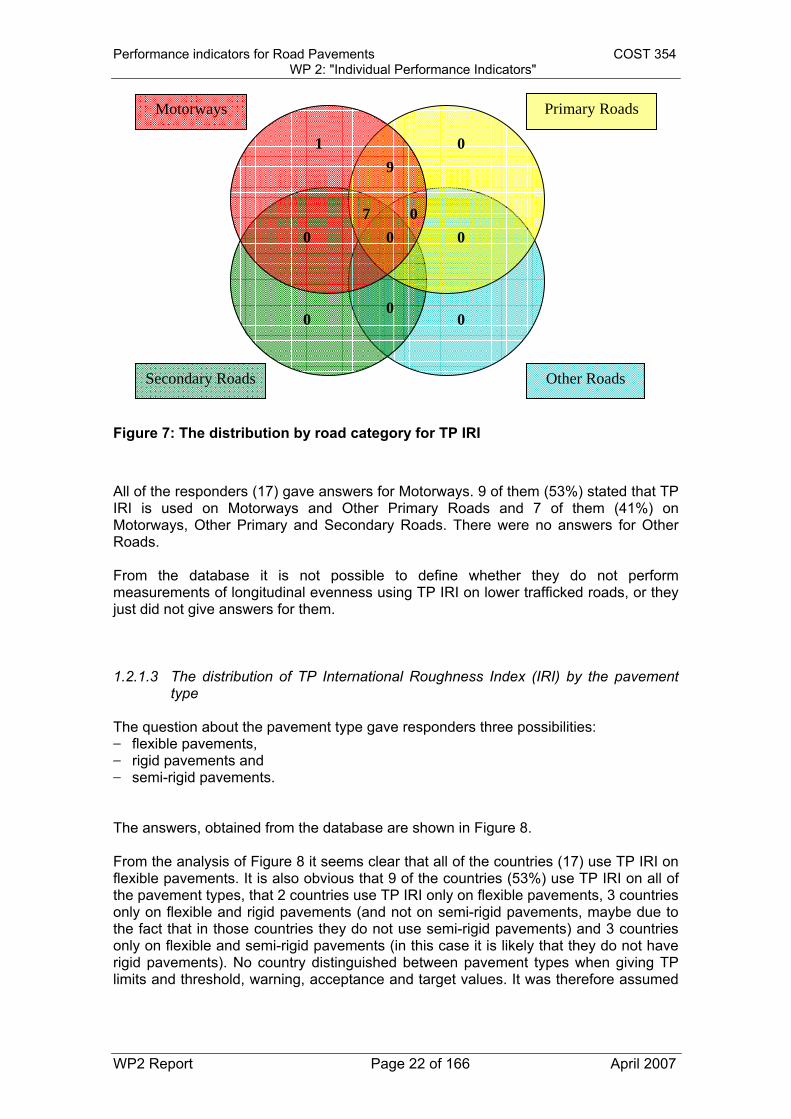
Figure 7: The distribution by road category for TP IRI All of the responders (17) gave answers for Motorways. 9 of them (53%) stated that TP IRI is used on Motorways and Other Primary Roads and 7 of them (41%) on Motorways, Other Primary and Secondary Roads. There were no answers for Other Roads. From the database it is not possible to define whether they do not perform measurements of longitudinal evenness using TP IRI on lower trafficked roads, or they just did not give answers for them. 1.2.1.3 The distribution of TP International Roughness Index (IRI) by the pavement
type The question about the pavement type gave responders three possibilities: flexible pavements, rigid pavements and semi-rigid pavements. The answers, obtained from the database are shown in Figure 8. From the analysis of Figure 8 it seems clear that all of the countries (17) use TP IRI on flexible pavements. It is also obvious that 9 of the countries (53%) use TP IRI on all of the pavement types, that 2 countries use TP IRI only on flexible pavements, 3 countries only on flexible and rigid pavements (and not on semi-rigid pavements, maybe due to the fact that in those countries they do not use semi-rigid pavements) and 3 countries only on flexible and semi-rigid pavements (in this case it is likely that they do not have rigid pavements). No country distinguished between pavement types when giving TP limits and threshold, warning, acceptance and target values. It was therefore assumed

Performance indicators for Road Pavements COST 354 WP 2: "Individual Performance Indicators"
WP2 Report Page 23 of 166 April 2007
that TP IRI is used on all pavement types and that TP limits and index limits are independent of the pavement type.
Semi-rigid Pavements
3
Flexible Pavement
Rigid Pavements
2
3 9
0 0 0
Figure 8: The distribution by the pavement type for the TP IRI 1.2.1.4 Distribution by the type of application The question about the type of application gave responders two possibilities: standard application and application for research. Figure 9 shows the distribution by the type of application for TP IRI. 2 of the responders gave no indication therefore there are 15 answers analysed. 13 responders stated that they use the TP IRI as a standard application. 2 countries use TP IRI only for research.

Performance indicators for Road Pavements COST 354 WP 2: "Individual Performance Indicators"
WP2 Report Page 24 of 166 April 2007
Standard application Application for research
11 2 2
Figure 9: The distribution by the type of application for the longitudinal evenness performance indicator
1.2.1.5 Measuring interval for TP International Roughness Index (IRI) The measuring interval for technical parameter IRI is shown in Figure 10.
Figure 10: Number of answers for measuring interval for technical parameter IRI The majority of countries perform measurements of IRI every year (35%).

Performance indicators for Road Pavements COST 354 WP 2: "Individual Performance Indicators"
WP2 Report Page 25 of 166 April 2007
1.2.2 Technical Parameters Wavelength, Evenness and Longitudinal Profile Variance
From the 29 records of longitudinal evenness performance indicators analysed, 5 refer to the technical parameter Wavelength (from 2 questionnaires), in 4 records (3 are from the same questionnaire) the technical parameter is Evenness and in 3 records the technical parameter is Longitudinal Profile Variance (all from 1 questionnaire). Because those technical parameters are used only in a country or two they are not analysed to the same level of detail as the technical parameter IRI. In Table 4 to Table 6 the information about the data collection for technical parameters Wavelength, Evenness and Longitudinal Profile Variance are summarized. Wavelength In order to perform wave band analysis, the pre-processed profile is split into different wave band limited profiles using filters. The definition of the wave bands used as well as the characteristics of the filters used to obtain band limited signals, from the original longitudinal profile must be given. How indices are derived from the band limited signals must also be defined. In most cases the profile can be adequately described as a sum of sine functions such as:
( )⎟⎠⎞
⎜⎝⎛
Λ−⋅
⋅ 02sin
xxA
π
where Λ defines the wavelength of the sine in metres, A is the amplitude of the sine in metres, x is the abscissa of the current point in metres, x0 is the phase of the sine in metres. The measuring procedure often follows a national standard, as in France (mechanical profilometer for short, medium and long wavelength), in Germany (wavelength with laser) and in Belgium (accelerometer with laser). Evenness A profile is the intersection between the surface of the pavement and the plane which contains both the vertical of the measured pavement and the line of travel of the measuring instrument. When the measuring instrument travels in a curve the line of travel is the tangent to that curve, when travelling in a straight line the line of travel is this line. In this plane, a point of the profile can be adequately described by its coordinates x (abscissa) and z (elevation), in any orthonormal reference system (X, Z), where Z is parallel to the aforementioned vertical. A longitudinal profile is one of the profiles obtained when the measuring instrument travels in the same direction as the usual traffic. Usually one of the profiles measured in the wheel tracks is used.

Performance indicators for Road Pavements COST 354 WP 2: "Individual Performance Indicators"
WP2 Report Page 26 of 166 April 2007
The measuring procedure does not necessarily follow a national standard, as in Belgium (accelerometer). Longitudinal Profile Variance
The longitudinal profile variance is carried out by considering the differences between the profile and its moving average over three separate moving average lengths: 3 m, 10 m and 30 m. The level of roughness in the profile over the three moving average lengths is then reported as the 3 m, 10 m and 30 m "longitudinal profile variance", which is the square of the difference between the moving average of the profile and the measured profile. This type of technical parameter is used in the UK (laser with technical specification).

Performance indicators for Road Pavements COST 354 WP 2: "Individual Performance Indicators"
WP2 Report Page 27 of 166 April 2007
Table 4: Technical parameter “Wavelength” information from the database
COUNTRY STANDARD STANDARD NAME STANDARD PRACTICE
OR RESEARCH TYPE OF
INSPECTION COLLECTED DATAOPERATING
SPEED [Km/h]
SECTION LENGTH
[m] HOMOGENI-
ZATION INTERVAL
[years] QUALITY
ASSURANCE
FRANCE (FR) 1 National Standard NF 98218-3 Standard Measurement Severity 70 100 No 3 Yes
FRANCE (FR) 2 National Standard NF 98218-3 Standard Measurement Severity 70 100 No 3 Yes
FRANCE (FR) 3 National Standard NF 98218-3 Standard Measurement Severity 70 100 No 3 Yes
GERMANY (DE) 2 National Standard Contactless
Measurement Severity 100 No 4 Yes
GERMANY (DE) 3 National Standard Standard Contactless
Measurement Severity 100 No 4 Yes
Table 5: Technical parameter “Evenness” information from the database
COUNTRY STANDARD STANDARD NAME STANDARD PRACTICE
OR RESEARCH TYPE OF
INSPECTION COLLECTED
DATA OPERATING
SPEED [Km/h]
SECTION LENGTH
[m] HOMOGENI-
ZATION INTERVAL
[years] QUALITY
ASSURANCE
BELGIUM (BE) 1 National Standard Standaardbestek 250 Standard Contactless
Measurement Extension 35-55 100 No 2 Yes
BELGIUM (BE) 2 No Standard Standard Measurement Severity 21.6-72 100 Yes 2 Yes
BELGIUM (BE) 3 No Standard Standard Measurement Severity 21.6-72 100 No 2 Yes
CZECH REPUBLIC (CZ) National Standard
ČSN 73 6175 - Pavement Roughness Measurement Standard Contactless
Measurement Severity 35-90 Yes 5 Yes
Table 6: Technical parameter “Longitudinal profile variance” information from the database
COUNTRY STANDARD STANDARD NAME STANDARD PRACTICE
OR RESEARCH TYPE OF
INSPECTION COLLECTED
DATA OPERATING
SPEED [Km/h]
SECTION LENGTH
[m] HOMOGENI-
ZATION INTERVAL
[years] QUALITY
ASSURANCE
UNITED KINGDOM (UK) 1 Technical Specification
Interim Advice Note: Traffic Speed Condition Surveys Standard Contactless
Measurement Severity 20-100 10 No 1 Yes
UNITED KINGDOM (UK) 2 Technical Specification
Interim Advice Note: Traffic Speed Condition Surveys Standard Contactless
Measurement Severity 20-100 10 No 1 Yes
UNITED KINGDOM (UK) 3 Technical Specification
Interim Advice Note: Traffic Speed Condition Surveys Standard Contactless
Measurement Severity 20-100 10 No 1 Yes

Performance indicators for Road Pavements COST 354 WP 2: "Individual Performance Indicators"
WP2 Report Page 28 of 166 April 2007
1.3 SELECTION OF THE PROPOSED INDIVIDUAL PERFORMANCE INDICATOR
In Working Group 2 a list of parameters was set up for the decision of the most suitable technical parameter for a specific performance indicator, namely:
1. Based on European standard (or international standard)? 2. Standard practice or research? 3. Wide use? 4. Device independent? 5. Safe to collect, both for operators and other road users e.g. traffic speed
collection (Operating speed, Type of inspection, Contactless measurement)? 6. Reliable (Quality assurance)? 7. Sustainable?
The result of the application of these criteria to longitudinal evenness technical parameters is shown in Table 7.
Table 7: Selection table for technical parameters TECHNICAL PARAMETER
IRI Wavelength Evenness Longitudinal Profile variance
BASED ON EUROPEAN STANDARD
STANDARD PRACTICE
RESEARCH
WIDE USE
DEVICE INDEPENDENT
SAFE TO COLLECT
RELIABLE N/A
SUSTAINABLE N/A
GOOD
MEDIUM
BAD
Based on the criteria listed above International Roughness Index (IRI) has been selected as single technical parameter for longitudinal evenness, as far as the current practice is concerned. From several studies it has become apparent that IRI might not be the best index to measure ride comfort on European roads. In some countries, systems have been developed, or are being developed, based on wavelength analysis on the measured longitudinal profiles. These types of systems are considered to be much better for the European roads (PARIS project (8)) and it can therefore be envisaged that soon there could be a much wider use of such indices.

Performance indicators for Road Pavements COST 354 WP 2: "Individual Performance Indicators"
WP2 Report Page 29 of 166 April 2007
1.4 PROTOCOLS AND TEST METHODS FOR MEASURING THE PROPOSED INDIVIDUAL INDICATOR
IRI is an index computed from a longitudinal road profile measurement using a virtual response type system, quarter-car simulation and running at a speed of 80 km/h (Figure 11). The simulation applied on the digitised road profile calculates the accumulated suspension motions divided by the distance travelled. The IRI has the unit of slope, e.g. mm/m or m/km. A complete computation of IRI is described in World Bank Technical Papers 45 and 46, [1], [2].with additional information in [3], [4] and [5]
Figure 11: the IRI model
IRI is a widely used and well established roughness index since it is considered to be a good indicator of pavement condition in respect to road roughness. It is developed in order to be linear, portable and stable with time. It is portable since it can be measured with a wide range of equipment giving the same results, and stable with time since it is defined as a mathematical transform of a measured profile, thus it is not affected by the measurement procedure nor the characteristics of the vehicle used for profile measurement.
1.4.1 Measurement equipment Today many different types of equipment have been developed around the world, and there are many different philosophies of how much must be measured in order to get a good picture of the pavement surface and to determine the longitudinal evenness of a road. The principles of physical measurement can be described in the following different categories [6]:
Geometric methods o rod and level measurements
Performance indicators for Road Pavements COST 354 WP 2: "Individual Performance Indicators"
WP2 Report Page 30 of 166 April 2007
o measurement of the difference between a straightedge and the pavement surface
o measurement with a horizontal laser beam as reference o measurement in relation to a moveable plane o measurement of the slope and inclination o superposition of measurement results from laser sensors positioned on
a straightedge Combination of geometric methods and accelerometer methods Initially held horizontal pendulum Distance measurement between vehicle axle and chassis Accelerometer signals
1.4.2 Calculation algorithms and data processing The European standard prEN 13036-6 – Surface Characteristics of Road and Airfield Pavements – Test Methods – Part 5: Determination of Longitudinal Unevenness Indices [7] standardises various possible characterisations of the road profile unevenness such as the International Roughness Index (IRI) computation procedure, wave bands analyses as well as Power Spectral Density (PSD) analyses. The computation of unevenness indices, involves three steps: the measurement and pre-processing of the profile, the output of which is a filtered and re-sampled (or pre-processed) profile, the computation of one or more index(es), and the creation of a report (Figure 12).

Performance indicators for Road Pavements COST 354 WP 2: "Individual Performance Indicators"
WP2 Report Page 31 of 166 April 2007
Figure 12: General overview of the IRI computation (1)
1.5 ASSESSMENT OF THE TRANSFORMATION FUNCTIONS
1.5.1 General information Each country created classes expressing the condition of the pavement (using a scale from very good to very poor) for their technical parameters. The aim of this COST action is to develop European harmonized individual performance indicators (or indices) which can then be combined into combined performance indicators and finally into general performance indicator (or index). To enable the combination of different individual performance indicators into combined performance indices it is necessary to convert each of the individual performance indicators into dimensionless index (i.e. scale from 0-very good to 5-very poor). Therefore an overview across individual countries’ classification was performed in this chapter. According to the Database different countries use different ways of classification to describe the condition of the pavement. Some use classification in three classes, some in five. Some countries transform TP to Indices and describe the condition of the pavement with indices, some use technical parameter limits to describe
MEASUREMENT
PRE-PROCESSING
RAW PROFILE
RE-SAMPLED and FILTERED PROFILE(pre-processed profile)
IRIComputation
WavebandIndices
Computation
PSDparameters
Computation
REPORT

Performance indicators for Road Pavements COST 354 WP 2: "Individual Performance Indicators"
WP2 Report Page 32 of 166 April 2007
the condition of the pavement and some use threshold, warning and acceptance limits of technical parameters. For the development of a European harmonized transformation function from IRI (m/km) to an IRI Index (dimensionless), a harmonized classification had to be developed (chapter 1.5.2). Once the harmonized classification was developed it was then possible to develop a harmonized transformation function (chapter 1.5.3).
1.5.2 Classification for technical parameter International Roughness Index (IRI) From the 29 records about the performance indicator longitudinal evenness analysed, 17 refer to the technical parameter “International Roughness Index”. From those 17 only 3 countries use transformation to a dimensionless Index, IRI (Table 8), of which only one actually gave two transformation functions from IRI to Index IRI with the classification criteria depending on road category. One country gave TP and Index limits for two traffic volumes. The third country gave transformation function and corresponding Index limits but no classification criteria. From the remaining 14 records, only 8 responders gave information about the classification of the technical parameter International Roughness Index, using TP limits or threshold, warning, acceptance and/or target values (Table 9). Some of them also stated that they use classification to indices but did not give any information about the transformation function from technical parameter to index. The remaining 6 records give no classification information and are excluded from further analyses.
Table 8: Transformation information for IRI to Index IRI from the database AUSTRIA (AT) POLAND (PL) SLOVENIA (SI) NAME OF TECHNICAL PARAMETER
International roughness index
International roughness index
International roughness index
MOTORWAYS Yes Yes Yes OTHER PRIMARY ROADS Yes Yes Yes SECONDARY ROADS No No Yes SECTION LENGTH 50 m 1000 m 100 m INDEX NAME Index roughness Index roughness Index roughness INDEX DESCRIPTION Index_IRI Representative IRI Index IRI NUMBER OF CLASSES 5 4 5 SCALE VERY POOR 5 D 5 SCALE VERY GOOD 1 A 0 NAME CLASS 1 1 – very good A – good very good NAME CLASS 2 2 – good B – fair good NAME CLASS 3 3 – fair C – poor fair NAME CLASS 4 4 – poor D - bad poor NAME CLASS 5 5 – very poor very poor
CLASSIFICATION CRITERIA 1 1.0<=I_IRI<=5.0; road category A and S AADT>2000 Or
ESAL82kN/day>80 CLASSIFICATION FUNCTION 1 1+0.7778*IRI 10*IRIp THRESHOLD TP 1 4.5 5.7 THRESHOLD IND 1 4.5 57 WARNING TP 1 3 4.5 WARNING IND 1 3.5 44
CLASSIFICATION CRITERIA 2 1.0<=I_IRI<=5.0; road category B AADT<2000 Or
ESAL82kN/day<80

Performance indicators for Road Pavements COST 354 WP 2: "Individual Performance Indicators"
WP2 Report Page 33 of 166 April 2007
CLASSIFICATION FUNCTION 2 1+0.5833*IRI THRESHOLD TP 2 6 THRESHOLD IND 2 4.5 WARNING TP 2 3.8 WARNING IND 2 3.5 INDEX LIMIT 1 1 0 0 INDEX LIMIT 2 1.5 20 1 INDEX LIMIT 3 2.5 44 2 INDEX LIMIT 4 3.5 57 3 INDEX LIMIT 5 4.5 4 INDEX LIMIT 6 5 5 TP LIMIT 1 (CRITERIA 1) 0 0 0 TP LIMIT 2 (CRITERIA 1) 1 2 1.2 TP LIMIT 3 (CRITERIA 1) 1.8 4.4 1.5 TP LIMIT 4 (CRITERIA 1) 3 5.7 2.2 TP LIMIT 5 (CRITERIA 1) 4.5 3.1 TP LIMIT 1 (CRITERIA 2) 0 0 TP LIMIT 2 (CRITERIA 2) 0.9 2.6 TP LIMIT 3 (CRITERIA 2) 2.6 3.5 TP LIMIT 4 (CRITERIA 2) 3.8 4.3 TP LIMIT 5 (CRITERIA 2) 6 4.9

Performance indicators for Road Pavements COST 354 WP 2: "Individual Performance Indicators"
WP2 Report Page 34 of 166 April 2007
Table 9: TP limits information for IRI from the database
CROATIA (HR) DENMARK (DK) FINLAND (FI) HUNGARY (HU) ITALY (IT) NETHERLANDS (NL) PORTUGAL (PT) SERBIA AND MONTENEGRO (CS)
NAME OF TECHNICAL PARAMETER
International roughness index
International roughness index
International roughness index
International roughness index
International roughness index
International roughness index
International roughness index
International roughness index
MOTORWAYS Yes Yes Yes Yes Yes Yes Yes Yes OTHER PRIMARY ROADS Yes Yes Yes Yes Yes Yes No Yes SECONDARY ROADS YES (*) Yes Yes Yes No No No Yes SECTION LENGTH 100 m 1000 m 100 m 100 m 20 m 100 m N/A 25 m NUMBER OF CLASSES 5 5 5 5 3 5 SCALE VERY POOR 5 1 5 E 10 SCALE VERY GOOD 1 5 1 A 1 NAME CLASS 1 very good very good 1 A – Excellent Good very good NAME CLASS 2 good good 2 B – Good Fair good NAME CLASS 3 fair fair 3 C – Sufficient Poor fair NAME CLASS 4 poor poor 4 D – Mediocre poor NAME CLASS 5 very poor very poor 5 E – Poor very poor CLASSIFICATION CRITERIA 1
AADT < 1500
CLASSIFICATION CRITERIA 2
AADT 1500 - 6000
CLASSIFICATION CRITERIA 3
AADT > 6000
THRESHOLD TP 1 5 4.1 3.5 THRESHOLD TP 2 3.5 THRESHOLD TP 3 2.5 WARNING TP 1 3.5 2.6 ACCEPTANCE TP 1 2.5 TP LIMIT 1 (CRITERIA 1) 1 0 0 0 0 1 TP LIMIT 2 (CRITERIA 1) 1.5 1.5 1.5 1.5 2 2.5 TP LIMIT 3 (CRITERIA 1) 2.5 2.5 2.2 2 3 3.5 TP LIMIT 4 (CRITERIA 1) 3.5 5 3 2.5 5.5 TP LIMIT 5 (CRITERIA 1) 5 4.5 3 7 (*) information not in the COST database used for the analysis, obtained during the WG2 work. It is not included in the following distribution analyses.

Performance indicators for Road Pavements COST 354 WP 2: "Individual Performance Indicators"
WP2 Report Page 35 of 166 April 2007
For 3 responders that provided transformation from IRI to Index IRI, both TP limits and Index limits are available in the COST 354 database. Taking into account that the vast majority of countries do not use transformation into indices (they use TP limits to describe the condition of the pavement) further analyses have been made from the TP limits. For the further analyses some assumptions had to be made: Where only threshold level of the TP is provided it is assumed it represents the
limit between poor and very poor condition; Where only warning level of the TP is provided it is assumed it represents the
limit between fair and poor condition. Where no classification criterion is given it is assumed that TP limits and
threshold, warning and acceptance levels are given for motorways and other primary roads.
As the majority of countries use 5 condition classes to describe the condition of the pavement, a transformation of the database information was performed according to the above assumptions and all of the limits were distributed into 5 classes (Table 10). Classes were named very good, good, fair, poor and very poor.
Table 10: TP limits for IRI Country Very good Good Fair Poor Very poor Section length [m]
AUSTRIA (AT) < 1,0 1,0 to 1,8 1,8 to 3,0 3,0 to 4,5 > 4,5 50
CROATIA (HR) < 1,5 1,5 to 2,5 2,5 to 3,5 3,5 to 5,0 > 5,0 100
DENMARK (DK) < 1,5 1,5 to 2,5 2,5 to 5,0 > 5,0 1000
FINLAND (FI) 0,0 to 2,5 2,5 to 3,5 3,5 to 4,1 > 4,1 100
HUNGARY (HU) < 1,5 1,5 to 2,2 2,2 to 3,0 3,0 to 4,5 > 4,5 100
ITALY (IT) < 1,5 1,5 to 2,0 2,0 to 2,5 2,5 to 3,0 > 3,0 20
NETHERLANDS (NL) < 2,6 2,6 do 3,5 > 3,5 100
POLAND (PL) 0,0 to 2,0 2,0 to 4,4 4,4 to 5,7 > 5,7 1000
PORTUGAL (PT) 0,0 to 2,0 2,0 to 3,0 > 3,0 N/A(*)
SERBIA AND MONTENEGRO (CS) < 1,0 1,0 to 2,5 2,5 to 3,5 3,5 to 5,5 > 5,5 25
SLOVENIA (SI) < 1,2 1,2 to 1,5 1,5 to 2,2 2,2 to 3,1 > 3,1 100 (*) in the following analyses it is assumed to be < 100 m
The information from Table 10 was divided into two groups, according to the stated section length in the database. Figure 13 and Figure 14 show the TP limits for IRI on Motorways and Other Primary Roads for section length < 100 m and for section length ≥ 100 m, respectively.

Performance indicators for Road Pavements COST 354 WP 2: "Individual Performance Indicators"
WP2 Report Page 36 of 166 April 2007
TP IRI limits for Motorways and Other Primary Roads(Section length < 100 m)
AT
AT
AT
AT
IT
IT
CS
CS
CS
IT
IT
PT
PT
CS
0,0
1,0
2,0
3,0
4,0
5,0
6,0
Very good - Good Good - Fair Fair - Poor Poor - Very poor
TP IRI Condition class limits
TP
IRI l
imit
valu
e (m
/km
)
AT
IT
PT
CS
Figure 13: TP limits for IRI on Motorways and Other Primary Roads for section
length < 100 m
TP IRI limits for Motorways and Other Primary Roads(Section length >= 100 m)
HR
HR
HR
DK
DK
HU
SLO
SLO
SLO
NL
NLHR
DK
FIN
FIN
FIN
HU
HU
HU
SLO
0,0
1,0
2,0
3,0
4,0
5,0
6,0
Very good - Good Good - Fair Fair - Poor Poor - Very poor
TP IRI Condition class limits
TP
IRI l
imit
valu
e (m
/km
)
HR
DK
FIN
HU
SLO
NL
PL
Figure 14: Technical parameter limits for IRI on Motorways and Other Primary
Roads for section length ≥ 100 m

Performance indicators for Road Pavements COST 354 WP 2: "Individual Performance Indicators"
WP2 Report Page 37 of 166 April 2007
Because of large scatter of individual values in Figure 13 and Figure 14 and the lack of classification criteria regarding road category or traffic in the database already mentioned, another set of analyses was performed, where section length as a parameter was excluded. The information from Table 10 was divided into two groups. The first group contains the lower TP limits (More restrictive group) and the second group contains the higher ones (Less restrictive group) (Table 11).
Table 11: TP limits for IRI grouped in “more restrictive” and “less restrictive” values
Very good – Good Good – Fair Fair – Poor Poor – Very poor More restrictive group ITALY (IT) 1,5 2,0 2,5 3,0 NETHERLANDS (NL) 2,6 3,5 PORTUGAL (PT) 2,0 3,0 SLOVENIA (SI) 1,2 1,5 2,2 3,1 MIN 1,2 1,5 2,2 3,0 MAX 1,5 2,0 3,0 3,5 AVERAGE 1,3 1,8 2,6 3,2 Less restrictive group AUSTRIA (AT) 1,0 1,8 3,0 4,5 CROATIIA (HR) 1,5 2,5 3,5 5,0 DENMARK (DK) 1,5 2,5 5,0 FINLAND (FI) 2,5 3,5 4,1 HUNGARY (HU) 1,5 2,2 3,0 4,5 POLAND (PL) 2,0 4,4 5,7 SERBIA AND MONTENEGRO (CS) 1,0 2,5 3,5 5,0
MIN 1,0 1,8 3,0 4,1 MAX 1,5 2,5 4,4 5,7 AVERAGE 1,3 2,3 3,5 4,9
Figure 15 and Figure 16 are graphical presentations of the “More restrictive” group and the “Less restrictive” group of TP limits for IRI, respectively.
TP IRI limits for More restrictive group
MIN
MINMAX
MAX
MIN
MINMAX
MAXAVG; 1,8
AVG; 3,2
AVG; 2,6
AVG; 1,3
0,0
0,5
1,0
1,5
2,0
2,5
3,0
3,5
4,0
Very good - Good Good - Fair Fair - Poor Poor - Very poor
TP IRI Condition class limits
TP
IRI l
imit
valu
e (m
/km
MIN
MAX
AVG
Figure 15: Technical parameter limits for IRI in More restrictive group

Performance indicators for Road Pavements COST 354 WP 2: "Individual Performance Indicators"
WP2 Report Page 38 of 166 April 2007
TP IRI limits for Less restrictive group
MIN
MAX
MAX
MAX
MIN
MIN
MIN
MAX
AVG; 2,3
AVG; 3,5
AVG; 4,9
AVG; 1,3
0,0
0,5
1,0
1,5
2,0
2,5
3,0
3,5
4,0
4,5
5,0
5,5
6,0
Very good - Good Good - Fair Fair - Poor Poor - Very poor
TP IRI Condition class limits
TP
IRI l
imit
valu
e (m
Figure 16: Technical parameter limits for IRI in Less restrictive group The scatter is much lower for this approach, and therefore the average values of IRI limits for these groups were calculated.
1.5.3 Assessment of transformation functions for IRI For the definition of a transformation function it was necessary to associate to each “condition class” (“very good” to “very poor”) a PI range, as shown in Table 12. This can be different from the condition classification used in practice by the road administrations.
Table 12: Definition of condition classes for PI_E
Condition class name
PI_E
Very good [0 to 1) Good [1 to 2) Fair [2 to 3) Poor [3 to 4) Very poor [4 to 5]
From the TP limits and Index limits two transformation functions were derived, one for the More restrictive group and one for the Less restrictive group (Figure 17).

Performance indicators for Road Pavements COST 354 WP 2: "Individual Performance Indicators"
WP2 Report Page 39 of 166 April 2007
Transformation functions from IRI to Index evenness (I_E)
1,3
3,2
1,8
2,6
4,9
3,5
2,3
1,3
0,0
0,5
1,0
1,5
2,0
2,5
3,0
3,5
4,0
4,5
5,0
0,0 1,0 2,0 3,0 4,0 5,0 6,0IRI (m/km)
I_E
(-)
More restrictive groupLess restrictive groupTransformation function for more restrictive group Transformation function for less restrictive group
Very poor
Poor
Fair
Good
Very good
Figure 17: Proposed transformation functions from TP IRI to PI_E The proposed mathematical transformation functions from IRI to PI_E are as follows:
For the more restrictive group: PI_E = MIN (5;0.1733·IRI2+0.7142·IRI-0.0316) with IRI in mm/m
For the less restrictive group:
PI_E = MIN (5; 0.816·IRI) with IRI in mm/m The proposed Index limits and corresponding IRI are shown in Table 13.
Table 13: TP limits and PI_E limits
Condition class name
PI_E IRI for More restrictive group
IRI for Less restrictive group
Very good [0 to 1) < 1,1 < 1,2
Good [1 to 2) 1,1 to 1,9 1,2 to 2,5
Fair [2 to 3) 1,9 to 2,6 2,5 to 3,7
Poor [3 to 4) 2,6 to 3,2 3,7 to 4,9
Very poor [4 to 5] > 3,2 > 4,9
Performance indicators for Road Pavements COST 354 WP 2: "Individual Performance Indicators"
WP2 Report Page 40 of 166 April 2007
1.5.4 Technical Parameters Wavelength, Evenness and Longitudinal Profile Variance
Although the majority of European countries use IRI as technical parameter describing the longitudinal evenness of a pavement, some countries use other technical parameters: Wavelength, Evenness Longitudinal Profile Variance. Table 14 includes the information about the transformation of those technical parameters from the database, where available.

Performance indicators for Road Pavements COST 354 WP 2: "Individual Performance Indicators"
WP2 Report Page 41 of 166 April 2007
Table 14: TP limits information for other longitudinal evenness technical parameters from the database TRANSFORMATION
COUNTRY NAME OF
TECHNICAL PARAMETER
INDEX NAME
INDEX DESCRIPTION
NUMBER OF
CLASSES
SCALE VERY POOR
SCALE VERY GOOD CRITERIA 1 FUNCTION 1 CRITERIA 2 FUNCTION 2 CRITERIA 3 FUNCTION 3 CRITERIA 4 FUNCTION 4
BELGIUM (BE) 1 Evenness Index roughness index evenness 5 0 1 Motorways 1-VLK/400 Primary 1-VLK/400 Secondary 1-VLK/400
BELGIUM (BE) 2 Evenness 5 E A
BELGIUM (BE) 3 Evenness 5 E A
CZECH REPUBLIC (CZ) Evenness Index roughness Index IRI 5 5 1 for all 1.23*C^0.23
FRANCE (FR) 1 Wave length Index roughness
Short wavelength index
5 E A
FRANCE (FR) 2 Wave length Index roughness
Long wavelength index 5 E A
FRANCE (FR) 3 Wave length Index roughness
Medium wavelength index
5 E A
GERMANY (DE) 2 Wave length Index roughness
Index Periodical Unevenness 8 5 1
v<=0, function class 1
IF(v<=-0.549;1;3.5+v*4/(ln3))
v>0, function class 1
IF(v>0.549;5;3.5+v*2/(ln3)
GERMANY (DE) 3 Wave length Index roughness
Index Single Obstruction 8 5 1
v<=0, function class 1
IF(v<=-0.549;1;3.5+v*4/(ln3))
v>0, function class 1
IF(v>0.549;5;3.5+v*2/(ln3)
UNITED KINGDOM (UK) 1Longitudinal profile variance
Index roughness 3m LPV Index 4 4 1
3mLPV <0.7 (1), <0.8 (2), <1.4 (3)
1
3mLPV >=0.7 (1), >=0.8 (2), >=1.4 (3)
2
3mLPV >=2.2 (1), >=2.2 (2), >=3.8 (3)
3
3mLPV >=4.4 (1), >=5.5 (2), >=9.3 (3)
4
UNITED KINGDOM (UK) 2Longitudinal profile variance
Index roughness 10m LPV Index 4 4 1
mLPV <1.6 (1), <2.8 (2), <6.1 (3)
1
3mLPV >=1.6 (1), >=2.8 (2), >=6.1 (3)
2
3mLPV >=6.5 (1), >=8.6 (2), >=16.3 (3)
3
3mLPV >=14.7 (1), >=22.8 (2), >=36.6 (3)
4
UNITED KINGDOM (UK) 3Longitudinal profile variance
Index roughness 30m LPV Index 4 4 1
mLPV <22 (1), <30 (2), <48 (3)
1 3mLPV >=22 (1), >=30 (2), >=48 (3)
2 3mLPV >=66 (1), >=75 (2), >=97 (3)
3
3mLPV >=110 (1), >=121 (2), >=193 (3)
4

Performance indicators for Road Pavements COST 354 WP 2: "Individual Performance Indicators"
WP2 Report Page 42 of 166 April 2007
1.6 REFERENCES
1. Sayers, M.W., T.D. Gillespie, and W.D., Paterson Guidelines for the conduct
and calibration of Road Roughness Measurements. World Bank Technical Paper 45. World Bank, Washington, D.C., 1986
2. Sayers, M.W., T.D. Gillespie, and W.D., Paterson Guidelines for the conduct
and calibration of Road Roughness Measurements. World Bank Technical Paper 46. World Bank, Washington, D.C., 1986
3. Karamihas S.M., and T.D. Gillespie et al. “Guidelines for Longitudinal Pavement
Profile Measurement”, TRB - NCHRP Report 434, Washington D.C., 1999,
4. Sayers, M.W., “On the calculation of International Roughness Index from Longitudinal Road Profile” Transportation Research Record 1501, Transportation Research Board, pp. 1-12”, Washington D.C., 1995
5. ASTM, “Computing International Roughness Index of Roads from Longitudinal
Profile measurements”, E1926-98, ASTM Standards
6. International Experiment to Harmonize Longitudinal and Transverse Profile Measurement and Reporting Procedures, PIARC, 2000
7. prEN 13036-6 – Surface Characteristics of Road and Airfield Pavements – Test
Methods – Part 5: Determination of Longitudinal Unevenness Indices
8. PARIS Project “Performance analysis of road infrastructure”, Published by the EU, 1999 ISBN 92-828-7827-9

Performance indicators for Road Pavements COST 354 WP 2: "Individual Performance Indicators"
WP2 Report Page 43 of 166 April 2007
SECTION 2: TRANSVERSE EVENNESS
There are several different performance indicators for transverse evenness that are used in pavement management systems and road databases in different countries. They differ in their technical meaning, as well as in the way they are collected (manual or automated, equipment, speed and sampling interval) and in the purpose and level of application (construction quality control, or project or network level pavement management). The transverse evenness is very important for road safety and the rut depths should be limited to a certain value to avoid aquaplaning in wet conditions. The objective of this section is to evaluate the transverse evenness indicators available in the COST-354 database, as well as to provide evaluation of the transverse evenness indicators available in the literature. Based on the analysis of the available indicators, the recommendation for the appropriate transverse evenness indicators will be provided, together with the corresponding transformation functions.
2.1 TRANSVERSE EVENNESS INDICATORS FROM THE COST 354 DATABASE
The total number of countries that provided questionnaires in the COST 354 database is 24. However, two questionnaires (Romania and Bulgaria) were not used in the analysis because of their late arrival. Of the remaining 22 countries, 20 (90.9 %) submitted responses about transverse evenness. Most of these countries supplied one questionnaire each. However, Belgium and France submitted two questionnaires each. Italy and Spain did not provide data regarding transverse evenness performance indicators. The list of countries that submitted questionnaires, together with the number of records is presented in Table 15. Several countries provided data about more than one index, and therefore, the total number of records analyzed is 36. Two records (“faulting” and “patch deterioration”) had been associated with transverse evenness performance indicator (PI) but they have both been excluded from the further analysis, which reduced number of processed records to 34. Analyzing the database further it was found that several answers from one country refer to different measuring devices or different technical parameters and therefore it is correct that they are included in further analyses. In some instances (i.e. France) there were multiple records for the same technical parameter (rut depths in left and right wheel paths, water heights in left and right wheel paths, or simply four records named “rut depth” that refer to the extend and severity of the rutting). If the same methodology, transformation functions and threshold values were used for data processing, these records were merged for the analysis. In the case of Czech Republic there were two answers for the same performance indicator and the only difference between them was the Field of Application (the first for Motorways and Other Primary Roads and the second one for Secondary Roads and

Performance indicators for Road Pavements COST 354 WP 2: "Individual Performance Indicators"
WP2 Report Page 44 of 166 April 2007
Other Roads), resulting in the difference only in threshold values and transformation functions of indices. These records were also merged for the analysis. Therefore the total number of records analyzed was 28, and they are presented in Table 15.
Table 15: Numbers of countries, questionnaires and records referred to the transverse evenness performance indicator
Country Total Transverse evenness Nº
Questionnaires Nº
QuestionnairesNº
Records Total
Nº Records Analysed
Austria 1 1 1 1 Belgium 2 2 3 2 Croatia 1 1 1 1 Czech Republic 1 1 2 1 Denmark 1 1 1 1 Finland 1 1 1 1 France 2 2 9 4 Germany 1 1 2 2 Greece 1 1 1 1 Hungary 1 1 1 1 Italy 1 Netherlands 1 1 1 1 Norway 1 1 2 2 Poland 1 1 1 1 Portugal 1 1 1 1 Serbia and Montenegro
1 1 1 1
Slovenia 1 1 1 1 Spain 1 Sweden 1 1 3 3 Switzerland 1 1 1 1 United kingdom 1 1 1 1 United States of America
1 1 2 1
TOTAL 24 22 36 28
2.1.1 General information In the COST 354 database there are 4 different technical parameters (TP) describing the transverse evenness performance indicator: Rut Depth Cross-fall Water Height Edge Deformation

Performance indicators for Road Pavements COST 354 WP 2: "Individual Performance Indicators"
WP2 Report Page 45 of 166 April 2007
Table 16 shows the overview of the transversal profile performance indicators, which includes the name of the TP, the description, the unit, the equipment name and the measuring principle reported in the database.

Performance indicators for Road Pavements COST 354 WP 2: "Individual Performance Indicators"
WP2 Report Page 46 of 166 April 2007
Table 16: Description of transverse evenness technical parameters from the COST-354 database COUNTRY NAME NAME TP (Unified) TP DESCRIPTION UNIT EQUIPMENT NAME MEASURING PRINCIPLE AUSTRIA (AT) Transverse evenness Rut depth Rut depth mm RoadSTAR Laser
BELGIUM (BE) 1 Rutting Rut depth Rutting mm ARAN Ultrasonic
BELGIUM (BE) 2 Transverse evenness Rut depth Ornière caractéristique mm TUS Ultrasonic
CROATIA (HR) Transverse evenness Rut depth Rut depth mm Laser profilograph (DK) Laser
CZECH REPUBLIC (CZ) Transverse evenness Rut depth Rut depth – 2 records mm ARAN Laser
DENMARK (DK) Rutting Rut depth Rut depth mm Profilograph Laser
FINLAND (FI) Transverse evenness Rut depth Rut depth mm RST Laser
FRANCE (FR) 1 Transverse profile Water height Water height – 2 records (in right and left wheel paths) mm PALAS Laser
FRANCE (FR) 2 Transverse profile Rut depth Rut depth – 2 records (in right and left wheel paths) mm PALAS Laser
FRANCE (FR) 3 Transverse profile Cross-fall Transverse slope % PALAS Laser
FRANCE (FR) 4 Rut depth Rut depth Rut depth – 4 records (Extend and Severity) mm TUS, PALAS Ultrasonic and laser
GERMANY (DE) 1 Transverse evenness Water height Fictive water depth mm Laser
GERMANY (DE) 2 Transverse evenness Rut depth Rut depth mm Laser
GREECE (EL) Transverse evenness Rut depth Rut depth mm
HUNGARY (HU) Transversal unevenness Rut depth Rut depth mm Road Survey Tester (RST) Laser
NETHERLANDS (NL) Transverse evenness Rut depth Rut depth mm ARAN Ultrasonic
NORWAY (NO) 1 Transverse evenness Rut depth Rut depth mm ALFRED Ultrasonic
NORWAY (NO) 2 Transverse evenness Cross-fall Cross-fall % ALFRED Ultrasonic
POLAND (PL) Transverse evenness Rut depth Rut depth mm Greenwood Profilograph Laser
PORTUGAL (PT) Transverse evenness Rut depth Rut depth mm Laser profilometer Laser SERBIA AND MONTENEGRO (CS) Transverse evenness Rut depth Rut depth mm Straightedge and pin Manual measurement
SLOVENIA (SI) Transverse evenness Rut depth Rut depth mm 4 m straight edge Manual measurement
SWEDEN (SE) 1 Edge deformation Edge deformation Transverse profile mm Laser RST Laser
SWEDEN (SE) 2 Geometrical/Transversal unevenness Cross-fall Cross-fall % Laser RST Laser
SWEDEN (SE) 3 Transverse unevenness Rut depth Rut depth mm Laser RST Laser
SWITZERLAND (CH) Transverse evenness Rut depth Rut depth mm
UNITED KINGDOM (UK) Rut depth Rut depth Rut depth mm Road Assessment Vehicle (RAV) Laser
USA (US) Transverse evenness Rut depth Rut depth mm ARAN Laser

Performance indicators for Road Pavements COST 354 WP 2: "Individual Performance Indicators"
WP2 Report Page 47 of 166 April 2007
In most of the cases where data is available, the “Rut Depth” is used as the technical parameter for transverse evenness (22 out of 28 total answers). In three of the records the technical parameter is “Cross-fall”, in two records “Water Height” and there is one record where the technical parameter is the “Edge Deformation”. Figure 18 and Table 17 provide a summary of analyzed technical parameters and corresponding countries where they are used.
Figure 18: Technical parameters for transverse evenness performance indicator
Table 17: Summary of technical parameters specified for the transverse evenness
Technical Parameter
Nº Countries
Nº Records Analyzed
Countries
Rut Depth 20 22 AT, BE(2), CH, CS, CZ, DE, DK, EL, FI, FR(2), HR, HU, NL, NO, PL, PT, SE, SI, UK, US
Cross-fall 3 3 FR, NO, SE Water Height 2 2 DE, FR Edge Deformation 1 1 SE
2.1.2 Category of performance indicator All responders classified transverse evenness as a Road Safety PI. In addition, 11 of them (39.3 %) classified it as index related to Riding Comfort, 1 (3.6 %) as index related to Pavement Structure, and 11 (39.3 %) as index related to both Riding Comfort and Pavement Structure. It should be noted that for the French TP that was created from four records (i.e. FRANCE (FR) 4), two of these records are classified as Riding Comfort PI, and two as Pavement Structure PI. For this analysis this TP was counted as being related to both Riding Comfort and Pavement Structure.

Performance indicators for Road Pavements COST 354 WP 2: "Individual Performance Indicators"
WP2 Report Page 48 of 166 April 2007
The distribution by category is presented in Figure 19.
Figure 19: Distribution of transverse evenness PI by category
2.1.3 Field of application – distribution by road network Most of the answers specified that transverse evenness PIs are used on motorways alone (5 answers or 17.9 %), motorways and primary roads (8 answers or 28.6 %) or motorways, primary and secondary roads (12 answers or 42.9 %). Three performance indicators (10.7 %) are being used on all four road categories (Figure 20). As previously said, for two merged records from the Czech Republic the only difference was the field of application and this record is included in the last category. It appears that transverse evenness performance indicators are primarily used on higher trafficked roads.
Figure 20: Distribution of Transverse evenness PI by road network

Performance indicators for Road Pavements COST 354 WP 2: "Individual Performance Indicators"
WP2 Report Page 49 of 166 April 2007
The transverse profile data provided in the database indicate that for most of the countries, transverse profile performance indicators are used for all road categories provided in the COST 354 database. Two exceptions are Portugal and Slovenia which indicated that transversal profile PIs are only used on motorways, although there are other indicators defined for other road categories. Also, in Germany and the Netherlands they are not used on the least trafficked road categories. According to the COST 354 database, it appears that Denmark is only collecting rutting data out of all other condition indicators on other/local roads.
2.1.4 Distribution by Level of Application The distribution by the level of application indicates that transverse evenness PIs are used either on network level (12 records – 42.9 %), or on network and project level (16 records – 57.1 %), as presented in Figure 21.
Figure 21: Distribution of Transverse evenness PI by Level of Application
2.1.5 Distribution by Pavement Type As expected, the transverse evenness PIs are primarily collected on flexible pavements. Six indicators (21.4 %) are used only on flexible pavements, 10 (35.7 %) on flexible and semi-rigid, 8 (28.6 %) on all three types of pavements, and 3 (10.7 %) on flexible and rigid. For one (3.6 %) indicator the pavement type was not specified (Figure 22).

Performance indicators for Road Pavements COST 354 WP 2: "Individual Performance Indicators"
WP2 Report Page 50 of 166 April 2007
Figure 22: Distribution by pavement type
2.1.6 Distribution by Type of Application The majority of transverse evenness PIs are used for standard purpose alone (21 or 75 %) or for both standard and research purposes (5 or 17.9 %). Only one indicator (3.6 %) is used for research only, and for one indicator (3.6 %) the type of application was not specified (Figure 23). The detailed distribution by performance indicator is presented in Figure 24. It is interesting to note that all transverse evenness PIs except “rut depth” are used for standard practice.
Figure 23: Distribution by type of application

Performance indicators for Road Pavements COST 354 WP 2: "Individual Performance Indicators"
WP2 Report Page 51 of 166 April 2007
21
15
3 2 1
5
5
1
1
1
1
0
5
10
15
20
25
30
Total Rut Depth Crossfall Water Height EdgeDeformation
Technical Parameter
Num
ber o
f ans
wer
s
Standard Standard & Research Research Not specified
Figure 24: Number of answers grouped by the type of application for transverse evenness PIs
2.1.7 Standardization One of the questions in the COST 354 questionnaire was whether the technical parameter was measured according to a national or international standard (NS or IS) or a Technical Specification (TS). Table 18 and Figure 25 provide the answers related to the standards used. It can be concluded that the most common way of measuring the technical parameters is following a national standard.
Table 18: Standards and specifications used for transverse evenness performance indicators
Country Standard Technical Parameter
Austria NS: RVS 11.066 - Teil VII, (Roadstar) Rut Depth Belgium 1 NS: Standaard-bestek 250 Rut Depth Belgium 2 No standard Rut Depth
Czech Republic NS: ČSN 73 6175 - Pavement Roughness Measurement Rut Depth Croatia No Standard Rut Depth
Denmark NS: Konstruktion og vedligehold af veje og stier, Hæfte 4,
Vedlige-hold af fær-dselsarealet, Juni 2004. Comming CEN-standard #prEN 13036-5
Rut Depth
Finland NS: National Standard Rut Depth France 1 Water Height France 2
NS : NFP 219-1 Rut depth

Performance indicators for Road Pavements COST 354 WP 2: "Individual Performance Indicators"
WP2 Report Page 52 of 166 April 2007
France 3 Cross-fall France 4 NS : Méthode LPC n° 49 Rut Depth
Germany 1 Water Height Germany 2
NS: National Standard Rut Depth
Great Britain TS :Interim Advice Note : Traffic Speed Condition Surveys – Revised Assessment Criteria Rut Depth
Greece NS : Greek Specifications (P.T.P) Rut Depth
Hungary TS : ÚT 2-2.116/1998 RST-mérés és –értéke-lés (RST-measurement and evaluation) Rut Depth
Netherland TS Rut Depth Norway 1 Rut Depth Norway 2
NS: ALFRED measurements manual Cross-fall
Poland No Standard: System Oceny Stanu Nawierzchni - Wytyczne stosowania, Załącznik C Rut Depth
Portugal No Standard Rut Depth Serbia and Montenegro TS: AASHTO guidance Rut Depth
Slovenia TS: TSC 06.610: 2003 Lastnosti voznih površin, Ravnost (Pavement surface properties, Evenness) Rut Depth
Sweden 1 Edge Deformation Sweden 2 Cross-fall Sweden 3
National Standard : MB115 & MB116 Rut Depth
Switzerland NS : SN 640 520a "Planéité" Rut Depth
United States of America NS: AASHTO PP38-00: Standard Practice for Determining Maximum Rut Depth in Asphalt Pavements Rut Depth
19
13
3 2 1
5
5
4
4
0
5
10
15
20
25
30
Total Rut Depth Crossfall Water Height EdgeDeformation
Technical Parameter
Num
ber o
f ans
wer
s
National Standard Technical Specification No Standard
Figure 25: Number of answers grouped by the type of standard for TP of transverse evenness

Performance indicators for Road Pavements COST 354 WP 2: "Individual Performance Indicators"
WP2 Report Page 53 of 166 April 2007
2.1.8 Measuring principle The records included in the COST 354 database about the measuring principle for transverse evenness TPs are presented in Figure 26. The measuring principle and device used for surveys is a very important issue for the transverse evenness performance indicators, particularly when the technical parameter is the rut depth or water height. The results of the FILTER experiment (2) carried out a few years ago showed that measured technical parameters are very sensitive to the equipment used, particularly on number of sensors and measurement width. Therefore, in addition to the survey device/sensor type used, more details are needed to be able to summarize transverse evenness measurements. A summary of these characteristics is presented in Table 19.
In most countries where automatic survey equipment is used, and according to the available data, the survey width varied between 2 and 3.5 m and the number of sensors varied between 13 and 37. The sampling interval was available only for four countries, but was consistently set to 0.1 m.
18
13
2 2 1
5
4
1
1
1
2
2
2
2
0
5
10
15
20
25
30
Total Rut Depth Crossfall Water Height EdgeDeformation
Technical Parameter
Num
ber o
f ans
wer
s
Laser Ultrasonic Ultrasonic & Laser Manual Not specified
Figure 26: Number of records grouped by measuring principle for transverse evenness TPs

Performance indicators for Road Pavements COST 354 WP 2: "Individual Performance Indicators"
WP2 Report Page 54 of 166 April 2007
Table 19: Measuring principle details
Country Code Country
Meas. Principle/
Sensor Type # Sensors Measuring
Width Sampling Interval
RUT DEPTH AT Austria Laser 23 2 m BE Belgium 1 Ultrasonic BE Belgium 2 Ultrasonic 13 3 m HR Croatia Laser 10 2.75 0.1 m
CZ Czech Republic
Laser
DK Denmark Laser 25 3.2 m 0.1 m FI Finland Laser FR France 2 Laser 3.5 m FR France 4 Ultrasonic/Laser 13 (US) 3 m DE Germany 2 Laser EL Greece HU Hungary Laser 17 0.1 m NL Netherlands Ultrasonic 37 NO Norway 1 Ultrasonic 17 2 m PL Poland Laser 15 PT Portugal Laser
CS Serbia and Montenegro Manual
SI Slovenia Manual SE Sweden 3 Laser 17 0.1 m CH Switzerland
UK United Kingdom
Laser 20 0.1 m
US United States of America Laser
CROSSFALL FR France 3 Laser 3.5 m NO Norway 1 Ultrasonic 23 2 m SE Sweden 2 Laser 17
WATER HEIGHT FR France 1 Laser 3.5 m DE Germany 1 Laser
EDGE DEFORMATION SE Sweden 1 Laser 17
In addition to the measuring principle, the data processing algorithm is also important. There are two basic algorithms that are used for calculation of rut depth: straightedge (with different possible lengths) or tensioned wire. The details of the calculation algorithms will be presented in paragraph 2.5.2 of this section.

Performance indicators for Road Pavements COST 354 WP 2: "Individual Performance Indicators"
WP2 Report Page 55 of 166 April 2007
In addition, it is important whether the average or maximum value of the left and right wheel path rut depth or water height is used in the analysis. Unfortunately, this data is mostly unavailable in the COST 354 database, as presented in Table 20.
Table 20: Algorithms used for processing of RUT DEPTH performance indicator data
Country Code Country Algorithm Width Section
Length
Max, Avg.
Left, Right Long Dir
Transv Dir AT Austria Straight edge 2 m 50 m
BE Belgium 1 Tensioned wire
100 m
BE Belgium 2 3 m 100 m HR Croatia CZ Czech Republic 10 m DK Denmark 1000 m FI Finland 100 m FR France 2 Straight edge 1.5 m 10 m FR France 4 Straight edge 1.5 m 200 m DE Germany 2 100 m EL Greece Straight edge 3 m 10 m HU Hungary 100 m
NL Netherlands Tensioned wire
100 m
NO Norway 1 2 m
PL Poland Straight edge 2 m 1000 m (5
m in comment)
PT Portugal
CS Serbia and Montenegro Straight edge 1.2 m 25 m
SI Slovenia Straight edge 4 m 20 m
SE Sweden 3 Tensioned wire1 20 m Max, left,
right rut depthCH Switzerland Straight edge 4 m 50 m UK United Kingdom 10 m Average right
US United States of America 10 – 300 m
Note : 1According to the literature (3). Not present in the database Of course, if the measuring principles and data processing algorithms of the transverse evenness technical parameters are different, then the thresholds and decision values for the PIs related to these parameters, will probably be different as well.

Performance indicators for Road Pavements COST 354 WP 2: "Individual Performance Indicators"
WP2 Report Page 56 of 166 April 2007
2.1.9 Quality assurance Figure 27 presents the distribution of answers for quality assurance for transverse evenness technical parameters.
24
18
3 2 1
4
4
0
5
10
15
20
25
30
Total Rut Depth Crossfall Water Height EdgeDeformation
Technical Parameter
Num
ber o
f ans
wer
s
YES NO
Figure 27: Number of answers for quality assurance for technical parameters of transverse evenness
From the answers it can be concluded that quality assurance is taken into account while performing the transverse evenness surveys and data collection.
2.1.10 Measuring interval The measuring intervals for the Transverse Evenness technical parameters are presented in Figure 28.

Performance indicators for Road Pavements COST 354 WP 2: "Individual Performance Indicators"
WP2 Report Page 57 of 166 April 2007
Measuring Interal (years) for TE TP
21%
14%
29%
7%
11%
18%
1 2 3 4 5 NA
Figure 28: Number of answers for measuring interval (in years) of Transverse Evenness TPs
The majority of countries perform surveys on a 3-year interval (29%).
2.2 COMPLEMENTARY INFORMATION DERIVED FROM LITERATURE
This section provides the literature review of transverse evenness indicators defined in the proposed European standard and other literature sources.
2.2.1 Draft European Standards
The European standard prEN 13036-8 (2006) – Road and Airfield Surface Characteristics – Test Methods – Part 8: Transverse unevenness and irregularities, definitions, methods of evaluation and reporting (4) defines transversal unevenness and irregularities of the pavement surface of roads and airfields and appropriate methods of evaluation and reporting. The transverse evenness parameters defined in this standard are: • The cross-fall of the transverse profile; • The heights of different irregular defects in the transverse profile, like steps,
ridges/bumps/dips and edge deformation; • The rut depth in the wheel path; • The theoretical water depth in the ruts.
Cross-fall is defined as the angle between the horizontal and the regression straight line (according to least squares method) through the transverse profile fixed by at least seven measurement points equally spaced across the profile. This is the so called “regression-line method”.

Performance indicators for Road Pavements COST 354 WP 2: "Individual Performance Indicators"
WP2 Report Page 58 of 166 April 2007
The draft European standard also includes definition of several irregularities of the transverse profile. Although none of them, except edge deformation, is consistently measured in the countries participating in the COST-354, they are measures of localized irregularities and cannot be considered sufficient to characterize transversal profiles. The rut depth is defined using the straightedge method (Figure 29) as the maximum deviation of the transversal profile from the straightedge.
Figure 29: The definition of rut depth in left and right wheel paths according to
prEN 13036-8 (4) The calculation principle of the theoretical water depth according to prEN 13036-8 is shown in Figure 30. Theoretical water depth can be calculated separately for both wheel paths.
Figure 30: Calculation principle of water depths according to prEN 13036-8 (4)
2.2.2 FILTER – Theoretical Study of Indices – Technical Note 2000/02
The following transverse profile parameters were analyzed in the FILTER theoretical study of Indices (2):
• Maximum theoretical water depth • Maximum theoretical water depth in left rut • Maximum theoretical water depth in right rut • Area of water (sum of both ruts) • Maximum rut depth • Maximum rut depth in left rut

Performance indicators for Road Pavements COST 354 WP 2: "Individual Performance Indicators"
WP2 Report Page 59 of 166 April 2007
• Maximum rut depth in right rut • Area of rut (sum of both ruts)
The indices are defined according to the Figure 31, Figure 32 and Figure 33.
Figure 31: Definition of area of the rut (2)
Figure 32: Definition of maximum rut depth (2)
Figure 33: Definition of water area (2)
This study dealt with analysis of the impact of different variables on transverse profile survey results. Some of these conclusions, particularly regarding the impact of the number of sensors and the measurement width are presented in sections 2.5.3.2 and 2.5.3.3. 2.2.3 FHWA Report Characterization of Transverse Profiles, FHWA-RD-01-024,
April 2001.
This study (5) examined several indices and their correlations for the evaluation of transversal profiles on the LTPP sections:

Performance indicators for Road Pavements COST 354 WP 2: "Individual Performance Indicators"
WP2 Report Page 60 of 166 April 2007
• Area of rut below and area of pavement above the ideal straight line connecting the edges of the pavement
• Area between the straight lines connecting the maximum pavement elevation and pavement surface
• Maximum depth for each wheel-path between a 1.2-m straightedge across a wheel-path and the surface of the pavement below the straightedge
• Maximum depth for each wheel-path between a 1.8-m straightedge across a wheel-path and the surface of the pavement below the straightedge
• Maximum depth for the outside wheel-path between a horizontal line from the edge of the pavement and the surface (i.e. depth of water that may accumulate before drainage on the shoulder)
• Maximum depth for the inside wheel-path between a horizontal line from the maximum elevation between the wheel-paths and the surface (i.e. depth of water that may accumulate before drainage into the outer wheel-path assuming elevations in an adjacent lane to be greater than the maximum depth between the wheel-paths)
• Maximum depth for each wheel-path between the wire-line extended above the entire lane width and pavement surface
• Width of rut • Radius of curvature of deformation
It was concluded that the rut depth is the most widely used index for rutting, and many engineers have a good understanding of what the expected values of rut depths are. However, the disadvantage is that it provides a one-dimensional measure of the rutting and is not capable of describing the severity of rutting. The rut width provides the second dimension of rutting. However, this parameter is not usually measured. The “area” indices provide a two-dimensional measure of rutting. However, since the area parameters haven’t been measured and analyzed in the past, the disadvantage is that there is no good understanding of the range of the values. The study finally recommended that five indices should be added to the US National Information Management System:
• Area of rut below and area of pavement above the ideal straight line connecting the edges of the pavement
• Area between the straight lines connecting the maximum pavement elevation and pavement surface
• Maximum depth for each wheel-path between a 1.8-m straightedge across a wheel-path and the surface of the pavement below the straightedge
• Width of rut based on a 1.8-m straightedge. It was also concluded that the 1.8 m straightedge rut depth and the wire line rut depth provide the same measure of rut depth.
2.2.4 Potential additional transverse evenness indicators
Based on literature survey it can be concluded that all of the indicators used in European countries and are available in the COST 354 database are defined in the draft European standard prEN 13036-8 (4).
Performance indicators for Road Pavements COST 354 WP 2: "Individual Performance Indicators"
WP2 Report Page 61 of 166 April 2007
Since the rut depth and water height provide one-dimensional measures of rutting, including the other dimension (rut width) would possibly result in the improvement in the ability to describe severity of this distress. Therefore, the following indicators may be considered for measuring and evaluating transverse profiles:
• Area of rut (sum of both ruts) • Area of water (sum of both ruts) • Rut width
However, at this point, these indices are primarily used for research purposes and their major drawback is that they are neither widely used, nor defined in the standards.
2.3 EVALUATION OF THE MOST SUITABLE INDIVIDUAL PERFORMANCE INDICATORS
2.3.1 Technical parameter Rut Depth From the 28 records analyzed, 22 refer to technical parameter Rut Depth. Of those 22, only 5 countries provided explicit transformation functions for Index Rutting. However, two of them gave the transformation function and corresponding Index limits but no classification criteria. In addition, 6 countries provided TP limits that they obviously use to directly define classes. One country gave two classification criteria (depending on the traffic volume) and the corresponding Index limits, from which the two transformation functions could be derived. Some responders only gave information about the classification of the technical parameter Rut Depth, using TP limits or threshold, warning, acceptance and/or target values for the technical parameter Rut depth. Some of them also stated that they use classification to indices but did not give any information about the transformation function from technical parameter to index. Detailed data is presented in Table 21 and Table 22. Lack of classification criteria in the database could mean two things: limits between condition classes are independent of the road category or traffic or the responders forgot to provide the classification criteria. If no classification criteria were supplied then, for the purposes of further analysis, it was assumed that the TP limits and threshold values apply to motorways and other primary roads. From Table 21 and Table 22 some conclusions were made: The majority of the countries use a 5-class classification from very good through
good, fair and poor to very poor condition; From the TP limits and PI limits a transformation function could be derived; For those records that provided the transformation function, both, the limits of TP and Index limits are available in the COST 354 database.

Performance indicators for Road Pavements COST 354 WP 2: "Individual Performance Indicators"
WP2 Report Page 62 of 166 April 2007
Table 21: Technical parameter indices and transformation functions information for Rut Depth in the COST 354 database AUSTRIA (AT) BELGIUM (BE) 1 GERMANY (DE) POLAND (PL) SLOVENIA (SI) SWITZERLAND (CH)1 USA NAME OF TECHNICAL PARAMETER Rut Depth Rut Depth Rut Depth Rut Depth Rut Depth Rut Depth Rut Depth
MOTORWAYS Yes Yes Yes Yes Yes Yes Yes OTHER PRIMARY ROADS Yes Yes Yes Yes No Yes Yes SECONDARY ROADS No Yes Yes No No Yes No
INDEX NAME Index rutting Index rutting Index rutting Representative Rut Depth Rut Depth Index rutting Index rut depth
INDEX DESCRIPTION Index rutting Index rutting Index rut depth Representative Rut Depth Rut Depth Transverse Evenness
Index Rut Depth Index
NUMBER OF CLASSES 5 5 8 4 5 5 4 SCALE VERY POOR 5 0 Class 8 D 0 0 0 SCALE VERY GOOD 1 1 Class 1 A 5 100 100 NAME CLASS 1 1 – very good Very good Class 1 (good) A – good Very Good Good Good NAME CLASS 2 2 – good Good Class 2-5 (fair) B – fair Good Medium Fair NAME CLASS 3 3 – fair Fair Class 6-7 (poor) C – poor Fair Sufficient Poor NAME CLASS 4 4 – poor Poor Class 8 (very poor) D - bad Poor Critical Very poor NAME CLASS 5 5 – very poor Very poor Very Poor Bad CLASSIFICATION CRITERIA 1
1.0<=I_IRI<=5.0; road category A and S Function Class 1 AADT>2000 Or
ESAL82kN/day>80 Motorways
CLASSIFICATION FUNCTION 1 1+0.175*RT
1-0.05*RUT (RUT < 4)0.9-0.025*RUT (4-12) 1.2-0.05*RUT (12-16) 0.8-0.025*RUT (16-32)0 (RUT > 32)
IF(SPT<=4;1;1.5+2*(SPT-4)/6), SPT < 10 IF(SPT>20;5;3.5+(SPT-10)/10), SPT >10
2*Hp 100-5.62*RT
THRESHOLD TP 1 20 16 20 30 9 THRESHOLD IND 1 4,5 0.4 4.5 60 50 WARNING TP 1 15 14 10 20 WARNING IND 1 3,5 0.5 3.5 40 CLASSIFICATION CRITERIA 2
1.0<=I_IRI<=5.0; road category B Function Class 2 AADT<2000 Or
ESAL82kN/day<80 Primary Roads
CLASSIFICATION FUNCTION 2 1+0.14*RT
IF(SPT<=4;1;1.5+2*(SPT-4)/11), SPT < 15 IF(SPT>25;5;3.5+(SPT-10)/10), SPT >15
THRESHOLD TP 2 25 25 THRESHOLD IND 2 4,5 4.5 WARNING TP 2 15 15 WARNING IND 2 3,5 3.5

Performance indicators for Road Pavements COST 354 WP 2: "Individual Performance Indicators"
WP2 Report Page 63 of 166 April 2007
AUSTRIA (AT) BELGIUM (BE) 1 GERMANY (DE) POLAND (PL) SLOVENIA (SI) SWITZERLAND (CH)1 USA CLASSIFICATION CRITERIA 3 Function Class 3 Secondary Roads
CLASSIFICATION FUNCTION 3
IF(SPT<=4;1;1.5+2*(SPT-4)/16), SPT < 20 IF(SPT>30;5;3.5+(SPT-20)/10), SPT > 20
THRESHOLD TP 3 30 THRESHOLD IND 3 4.5 WARNING TP 3 20 WARNING IND 3 3.5 INDEX LIMIT 1 1 1 1 0 0 0 INDEX LIMIT 2 1,5 0.8 1.5 10 1 25 INDEX LIMIT 3 2,5 0.6 3.5 20 2 50 INDEX LIMIT 4 3,5 0.4 4.5 30 3 75 INDEX LIMIT 5 4,5 0.2 5 4 100 INDEX LIMIT 6 5 0 5 TP LIMIT 1 (CRITERIA 1) 0 02 0 0 0 TP LIMIT 2 (CRITERIA 1) 5 42 4 6 4 TP LIMIT 3 (CRITERIA 1) 10 122 10 10 6 9 TP LIMIT 4 (CRITERIA 1) 15 162 20 14 9 TP LIMIT 5 (CRITERIA 1) 20 322 18 12 TP LIMIT 1 (CRITERIA 2) 0 0 0 0 TP LIMIT 2 (CRITERIA 2) 5 4 8 5 TP LIMIT 3 (CRITERIA 2) 10 15 12 8 TP LIMIT 4 (CRITERIA 2) 15 25 16 12 TP LIMIT 5 (CRITERIA 2) 20 20 18 TP LIMIT 1 (CRITERIA 3) 0 0 0 TP LIMIT 2 (CRITERIA 3) 5 4 6 TP LIMIT 3 (CRITERIA 3) 10 20 10 TP LIMIT 4 (CRITERIA 3) 15 30 16 TP LIMIT 5 (CRITERIA 3) 20 24
Note: 1TP Limits are not in the database and are obtained from the provided literature 2Not in the corresponding fields in the database.
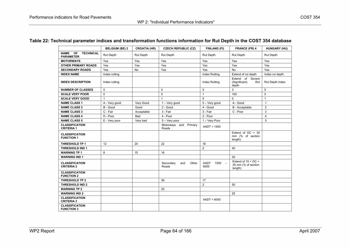
Performance indicators for Road Pavements COST 354 WP 2: "Individual Performance Indicators"
WP2 Report Page 64 of 166 April 2007
Table 22: Technical parameter indices and transformation functions information for Rut Depth in the COST 354 database BELGIUM (BE) 2 CROATIA (HR) CZECH REPUBLIC (CZ) FINLAND (FI) FRANCE (FR) 4 HUNGARY (HU) NAME OF TECHNICAL PARAMETER Rut Depth Rut Depth Rut Depth Rut Depth Rut Depth Rut Depth
MOTORWAYS Yes Yes Yes Yes Yes Yes OTHER PRIMARY ROADS Yes Yes Yes Yes Yes Yes SECONDARY ROADS Yes No Yes Yes No Yes INDEX NAME Index rutting Index Rutting Extend of rut depth Index rut depth
INDEX DESCRIPTION Index rutting
Index Rutting Extend of Severe (Significant) Rut depth
Rut Depth Index
NUMBER OF CLASSES 5 5 5 3 5 SCALE VERY POOR 0 5 1 100 5 SCALE VERY GOOD 1 1 5 0 1 NAME CLASS 1 A - Very good Very Good 1 – Very good 5 – Very good A - Good 1 NAME CLASS 2 B - Good Good 2 - Good 4 - Good B - Acceptable 2 NAME CLASS 3 C - Fair Acceptable 3 - Fair 3 - Fair C - Poor 3 NAME CLASS 4 D - Poor Bad 4 - Poor 2 - Poor 4 NAME CLASS 5 E - Very poor Very bad 5 – Very poor 1 – Very Poor 5 CLASSIFICATION CRITERIA 1
Motorways and Primary Roads AADT < 1500
CLASSIFICATION FUNCTION 1
Extend of OC > 30 mm (% of section length)
THRESHOLD TP 1 12 20 22 18 THRESHOLD IND 1 2 40 WARNING TP 1 8 15 16 WARNING IND 1 20
CLASSIFICATION CRITERIA 2
Secondary and Other Roads
AADT 1500 – 6000
Extend of 15 < OC < 30 mm (% of section length)
CLASSIFICATION FUNCTION 2
THRESHOLD TP 2 36 17 THRESHOLD IND 2 2 50 WARNING TP 2 25 WARNING IND 2 25 CLASSIFICATION CRITERIA 3
AADT > 6000
CLASSIFICATION FUNCTION 3
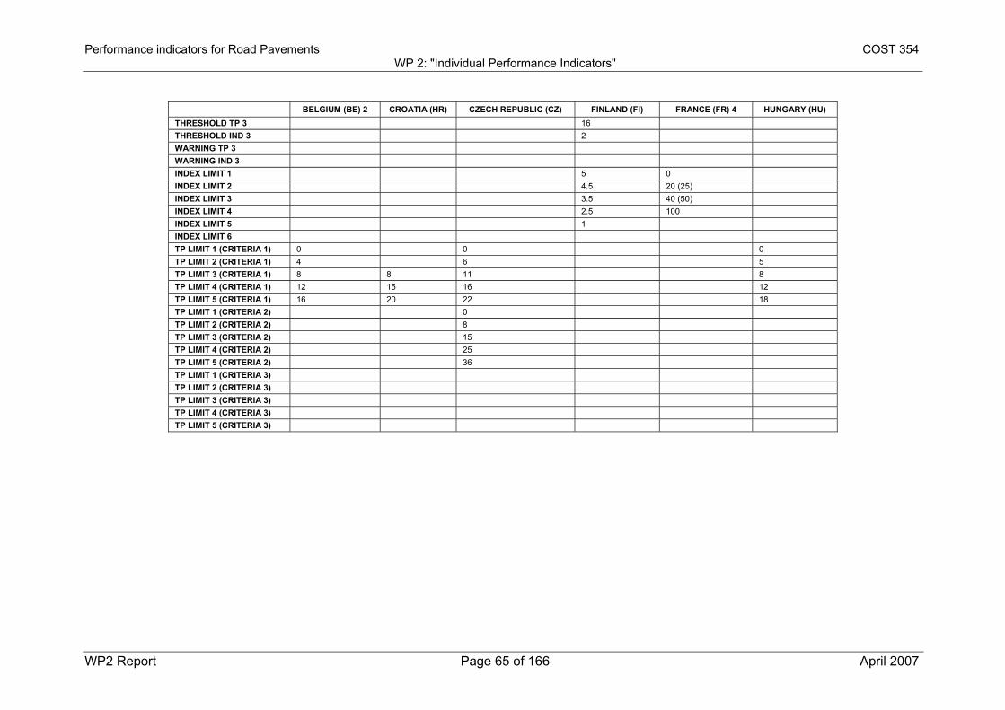
Performance indicators for Road Pavements COST 354 WP 2: "Individual Performance Indicators"
WP2 Report Page 65 of 166 April 2007
BELGIUM (BE) 2 CROATIA (HR) CZECH REPUBLIC (CZ) FINLAND (FI) FRANCE (FR) 4 HUNGARY (HU) THRESHOLD TP 3 16 THRESHOLD IND 3 2 WARNING TP 3 WARNING IND 3 INDEX LIMIT 1 5 0 INDEX LIMIT 2 4.5 20 (25) INDEX LIMIT 3 3.5 40 (50) INDEX LIMIT 4 2.5 100 INDEX LIMIT 5 1 INDEX LIMIT 6 TP LIMIT 1 (CRITERIA 1) 0 0 0 TP LIMIT 2 (CRITERIA 1) 4 6 5 TP LIMIT 3 (CRITERIA 1) 8 8 11 8 TP LIMIT 4 (CRITERIA 1) 12 15 16 12 TP LIMIT 5 (CRITERIA 1) 16 20 22 18 TP LIMIT 1 (CRITERIA 2) 0 TP LIMIT 2 (CRITERIA 2) 8 TP LIMIT 3 (CRITERIA 2) 15 TP LIMIT 4 (CRITERIA 2) 25 TP LIMIT 5 (CRITERIA 2) 36 TP LIMIT 1 (CRITERIA 3) TP LIMIT 2 (CRITERIA 3) TP LIMIT 3 (CRITERIA 3) TP LIMIT 4 (CRITERIA 3) TP LIMIT 5 (CRITERIA 3)
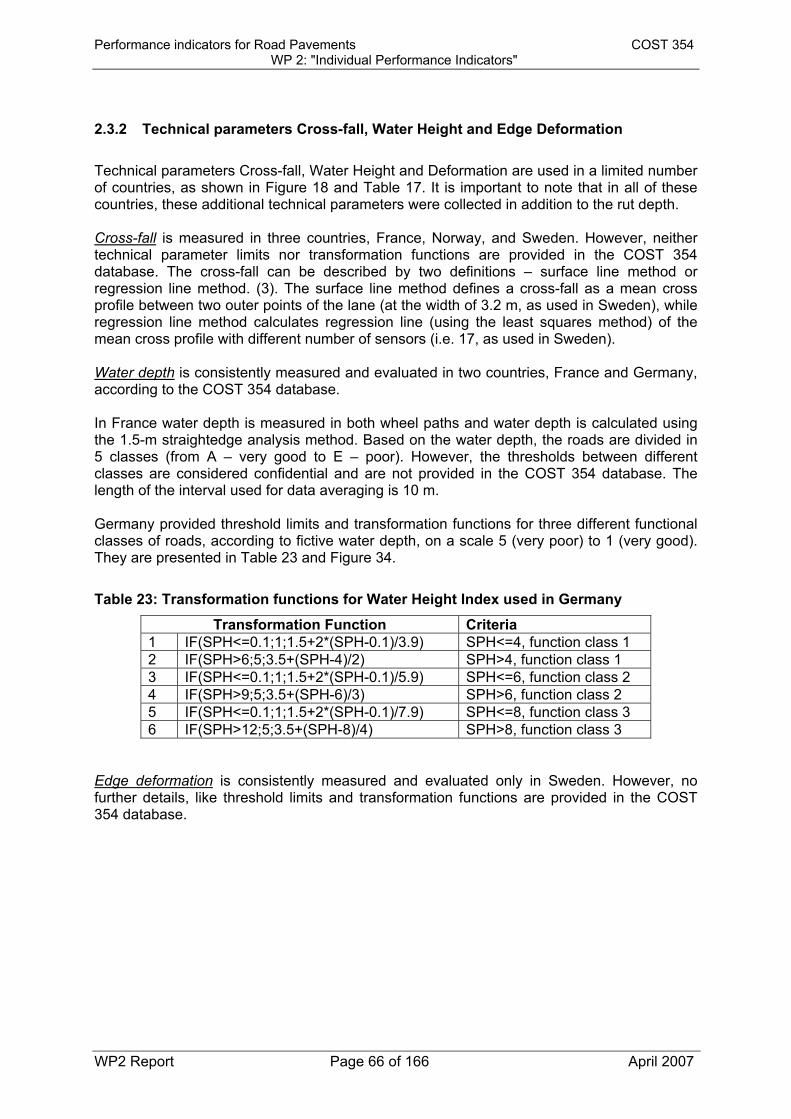
Performance indicators for Road Pavements COST 354 WP 2: "Individual Performance Indicators"
WP2 Report Page 66 of 166 April 2007
2.3.2 Technical parameters Cross-fall, Water Height and Edge Deformation Technical parameters Cross-fall, Water Height and Deformation are used in a limited number of countries, as shown in Figure 18 and Table 17. It is important to note that in all of these countries, these additional technical parameters were collected in addition to the rut depth. Cross-fall is measured in three countries, France, Norway, and Sweden. However, neither technical parameter limits nor transformation functions are provided in the COST 354 database. The cross-fall can be described by two definitions – surface line method or regression line method. (3). The surface line method defines a cross-fall as a mean cross profile between two outer points of the lane (at the width of 3.2 m, as used in Sweden), while regression line method calculates regression line (using the least squares method) of the mean cross profile with different number of sensors (i.e. 17, as used in Sweden). Water depth is consistently measured and evaluated in two countries, France and Germany, according to the COST 354 database. In France water depth is measured in both wheel paths and water depth is calculated using the 1.5-m straightedge analysis method. Based on the water depth, the roads are divided in 5 classes (from A – very good to E – poor). However, the thresholds between different classes are considered confidential and are not provided in the COST 354 database. The length of the interval used for data averaging is 10 m. Germany provided threshold limits and transformation functions for three different functional classes of roads, according to fictive water depth, on a scale 5 (very poor) to 1 (very good). They are presented in Table 23 and Figure 34.
Table 23: Transformation functions for Water Height Index used in Germany
Transformation Function Criteria 1 IF(SPH<=0.1;1;1.5+2*(SPH-0.1)/3.9) SPH<=4, function class 1 2 IF(SPH>6;5;3.5+(SPH-4)/2) SPH>4, function class 1 3 IF(SPH<=0.1;1;1.5+2*(SPH-0.1)/5.9) SPH<=6, function class 2 4 IF(SPH>9;5;3.5+(SPH-6)/3) SPH>6, function class 2 5 IF(SPH<=0.1;1;1.5+2*(SPH-0.1)/7.9) SPH<=8, function class 3 6 IF(SPH>12;5;3.5+(SPH-8)/4) SPH>8, function class 3
Edge deformation is consistently measured and evaluated only in Sweden. However, no further details, like threshold limits and transformation functions are provided in the COST 354 database.

Performance indicators for Road Pavements COST 354 WP 2: "Individual Performance Indicators"
WP2 Report Page 67 of 166 April 2007
1.00
1.50
2.00
2.50
3.00
3.50
4.00
4.50
5.00
0 1 2 3 4 5 6 7 8 9 10 11 12 13 14 15
Fictive Water Height (mm)
Inde
x
FC1 FC2 FC3
Warning Index
Threshold Index
Target Index
Figure 34: Transformation functions for Water Height Index used in Germany for
different road functional classes (FC)

Performance indicators for Road Pavements COST 354 WP 2: "Individual Performance Indicators"
WP2 Report Page 68 of 166 April 2007
2.4 SELECTION OF THE PROPOSED INDIVIDUAL PERFORMANCE INDICATOR
The decision on the most suitable technical parameter for a specific performance indicator was made using the criteria shown in 1.3. Based on data on the COST 354 database, all technical parameters (rut depth, water height, cross-fall, and edge deformation) currently present in the database and used in different European countries are also defined in the draft European standards for transverse profile measurements. As discussed earlier the use of these four parameters is primarily based on national standard or technical specifications. Three other parameters (rut area, water area and rut width) which are presented in chapter 2.2 of this report were not defined in the draft European standards nor in other standards, and they are primarily used for the research at this point. Regarding the wide use, it was obvious from the COST 354 database that rut depth is used in the majority of the countries participating in COST 354 Action as a technical parameter for transverse evenness. Cross-fall and water height are used in 3 and 2 countries respectively, and edge deformation in just one European country. Rut and water area and rut width are currently not used in any country. Device independency is relatively complicated issue. Since several different devices (manual and automated) are used for transverse profile surveys, there is significant number of parameters that influence the survey results. Among others, they include device type, sensor type, number of sensors, measurement width, and lateral position of the vehicle. Some of these parameters are even interrelated. However, the impact of these parameters is similar on all technical parameters considered, and therefore, all of them are rated as medium. Since all of the parameters can be collected with specialized vehicles at highway speeds, and that was the primary way of data collection at the network level, it was considered that their collection is safe. However, in the case of manual data collection this is not the case, but this way of data collection is rarely used at network level. The last two parameters (reliability and sustainability) were very difficult to estimate based on the available data in the database. Data presented in the FILTER report (1) provided some insight into importance of some variables on transverse profile measurements. In this report it was found that data collection speed has no significant influence on repeatability and reproducibility of the measurements. However, the averaging distances have significant influence on repeatability, but not on reproducibility of measurements. Average repeatability standard deviations were 0.1 % for cross-fall, 0.5 – 0.9 mm on rut depth and 0.25 mm on water height. Average reproducibility standard deviations were 0.5 % on cross-fall, 1.7 – 2.7 mm on rut depth and 2.1 – 2.2 mm on water height. The other parameters are not presented in the report. One important issue when reliability is considered is the type of survey equipment used for data collection. The laser sensors have slightly higher accuracy than ultrasonic sensors. However, both of them are mostly used for all of the parameters derived from transverse profile measurements, and it can be considered that they provide reliable data.

Performance indicators for Road Pavements COST 354 WP 2: "Individual Performance Indicators"
WP2 Report Page 69 of 166 April 2007
Since the same technology is used for collection of all considered technical parameters, it should be expected that this technology will be available in the future, and therefore, all parameters are considered sustainable. Table 24 presents all technical parameters and their evaluation regarding the specific criteria.
Table 24: Selection table for technical parameters
TECHNICAL PARAMETER
Rut Depth Cross-fall Water Height
Edge Deformation
Rut or Water Area
Rut Width
BASED ON EUROPEAN STANDARD
STANDARD PRACTICE
RESEARCH
WIDE USE
DEVICE INDEPENDENT
SAFE TO COLLECT
RELIABLE
SUSTAINABLE
GOOD
MEDIUM
BAD
Based on previous discussions, the technical parameter Rut Depth is selected as single technical parameter for transverse evenness, since it is used in most of the countries. Water height provides slightly higher reliability and is less dependent on the algorithm used for data processing. However, its major drawback for now is that it is only used in a few countries. Two other parameters from the COST 354 database, cross-fall and edge deformation, can be considered as additional parameters to describe transverse profile, but they are not sufficient by themselves to describe transverse evenness and can be hardly recommended as single performance indicators. Parameters derived from the literature, rut or water area and rut width are primarily used for research purposes at this point.

Performance indicators for Road Pavements COST 354 WP 2: "Individual Performance Indicators"
WP2 Report Page 70 of 166 April 2007
2.5 PROTOCOLS AND TEST METHODS FOR MEASURING THE PROPOSED INDIVIDUAL INDICATORS
According to prEN 13036-6 (6) transverse profile is the intersection between the road surface and a reference plane perpendicular to the road surface and to the lane direction There are several data collection protocols and data processing algorithms for measuring rut depths that are used in European countries and around the world. The results of the survey may be significantly influenced by the type and other parameters of the device, as well as by the calculation algorithms used. Therefore, the introductory part provides some basic information regarding the types of devices, their accuracy and other important characteristics.
2.5.1 Measurement equipment Devices used for transverse profile surveys can be roughly classified as manual or automated. Devices for manual surveys include: • Rod and level • Straightedge and pin (of various lengths) • Static and rolling Dipstick, and walking profiler. Rod and level surveys typically are not accurate enough to be used in PMS applications. Straightedges were mostly used in the past for project level rutting evaluation, while the dipstick or walking profilers are used for defining reference profiles and QC/QA surveys due to their high precision. According to the COST-354 database, straightedge is used in only two countries and no other manual devices are used. However, the straightedge and dipstick methods are defined in many standards. According to the draft European standard prEN 13036-8 (4), the following equipment can be used for transverse profile surveys: • Profilometer, according to the standard prEN 13036-6 (6) • Straightedge, according to the standard EN 13036-7 (7) • Measuring equipment that have proven to fulfil the required specifications, such as rod
and level. The accuracy classes that can be achieved with this equipment are presented in chapter 2.5.3. ASTM standard E1703/E1703M-95/2005– Standard Test Method for Measuring Rut-Depth of Pavement Surfaces Using a Straightedge (8) describes the procedure for measuring rut-depth at a chosen location with a straightedge. This standard allows use of straightedges from 1.73 m to 3.66 m (5.67 to 12 ft) long. The rut depth is defined as the maximum measured perpendicular distance between the bottom surface of the straightedge and the contact area of the gage with the pavement surface at a specific location. The most frequently used in the US are 4-ft (1.2 m) and 6-ft (1.5m) straightedges. AASHTO provisional standard PP 32-96/2000 – Standard Practice for Measuring Pavement Profile Using a Dipstick® (9) defines procedures for measuring both longitudinal and transverse profiles by measuring elevation differences using a dipstick. For measuring

Performance indicators for Road Pavements COST 354 WP 2: "Individual Performance Indicators"
WP2 Report Page 71 of 166 April 2007
transverse profiles, measurements are recorded at 0.3-m intervals and can be used to calculate rutting using various computational methods. ASTM standard E2133-03 – Standard Test Method for Using a Rolling Inclinometer to Measure Longitudinal and Transverse Profiles of a Travelled Surface (10) describes the measurement of transverse and longitudinal profiles using a rolling inclinometer at walking speeds. Transverse profile is defined as vertical deviations of the pavement surface form a horizontal reference perpendicular to the lane direction, and slope is defined as angular deviation of the travelled surface from the horizontal datum. This method can be used to measure rut depth using a computer simulation in accordance with standard ASTM E 1703/E 1703M (8). Automated measurements of rut depth can be performed using devices (profilometers) with different systems: • Ultrasonic • Laser (point and scanning) • Optical. Ultrasonic or point laser sensors are typically mounted on the rut beam in front of survey vehicle. The number of sensors varies between 3 (rarely used in some states in the US) and 132 and the measurement width between 2 and 3.5 m, depending upon the equipment type (11). Ultrasonic sensors are the lowest cost sensors spaced at approximately 100 mm intervals and measurement width of up to 3 m. Due to the speed of ultrasonic devices, these systems typically sample at every 2.5 – 5 m along the road. Point lasers give the elevation at a point (12). Since they are much faster than ultrasonic sensors, they can record transverse profile at intervals as close as 10 mm along the road. Scanning lasers is a relatively new technology that measures almost a continuous profile. For example, the Phoenix Science “Ladar” system samples a 3.5-m pavement width from a single scanning laser mounted 2.3 m above the ground. 950 points are sampled across the transverse profile, every 25 mm along the road (12). Optical systems use digitized images of the transverse profile which are analyzed to estimate rut depths. These images may be produced using different photographic techniques, often supplemented by lasers to project lines to the pavement and a special camera to measure deformations of the laser line. One type of this device is also used for data collection for LTPP in the US. The advantage of these automated devices is the high speed of data collection, but the disadvantage is the big variation among the devices, that is highly influenced by the transversal position of the vehicle during the measurement, especially for devices with a low number of sensors.
2.5.2 Calculation algorithms and data processing
The two basic principles used for the rut depth calculation are the straightedge and tensioned wire principles.

Performance indicators for Road Pavements COST 354 WP 2: "Individual Performance Indicators"
WP2 Report Page 72 of 166 April 2007
Figure 35 presents measuring of rut depth using a straightedge. There are several parameters that impact the value of rut depth calculated using this principle:
• Shape of the profile • Straightedge length • If rut depth is calculated as a vertical distance between the transverse profile and the
bottom of the straightedge, or as a distance measured perpendicular to the straight edge.
Figure 35: Straightedge method for determining rut depth (11) The length of the straightedge is a very important parameter when measuring and calculating the rut depth using this principle. According to the draft European standard prEN 13036-8 (4) the length of a virtual straight reference line should be about 1.5 to 2 m (about half the width of the lane). The tensioned wire method (Figure 36) relates the transverse profile to the straight line given by an ideal tensioned wire which touches the highest points in the cross profile. With this line as a basis, it is possible to calculate the rutting as the distance between profile and the line. The method removes some of the variables introduced using a straight edge method (11).
Figure 36: Tensioned wire method for determining rut depth (11)

Performance indicators for Road Pavements COST 354 WP 2: "Individual Performance Indicators"
WP2 Report Page 73 of 166 April 2007
However, in the report (5) it was concluded that there are no significant differences between 1.8-m straightedge and tensioned wire algorithms for calculation of maximum rut depths. In Sweden (3), mean cross profile is used as a basis for many of the parameters that describe transverse evenness. It is calculated by setting the outer measurement point to zero and “excluding” the cross-fall. The “zeroed” mean cross profile is then calculated every 0.1 m and expressed as a mean value every 20 m. It is used to calculate the rut depths, but it can also be used in combination with cross-fall to calculate edge deformation, water height, or other parameters. The Long Term Pavement Performance Program (LTPP) Protocol for collecting rut data (16) uses a photographic technology that results in a series of approximately 30 x-y points that accurately describe the transverse surface of the travel or outer lane of the pavement at a particular location. The transverse profile is measured at intervals over 15.2 m in the 152-m LTPP section. These x-y points are used to determine the rut depth using a tensioned wire-line calculation method. Both wheel-path rut values are stored in the LTPP database. Comparisons of rutting were made using the average of the wheel-path rut depths. AASHTO provisional standard PP 38-00 – Standard Practice for Determining Maximum Rut Depth in Asphalt Pavements (13) describes five-point method and outlines a standard procedure for estimating and summarizing maximum rut depth in asphalt pavement surfaces. The standard also states that five points are the minimum number of points, and that measurement of more points on the transverse profile enhances the likelihood of identifying the maximum rut-depth. Its purpose is to produce consistent estimations for network-level pavement management, based on automated data collection equipment. The interval length used in the standard is 100 m.
2.5.3 Accuracy of measurements The draft European standard prEN 13036-8 (4) defines the requirements regarding the accuracy for different technical parameters and measurement methods defined in the standard. There are three accuracy classes that depend on the type of survey equipment and the technical parameter used. Table 25 provides the combination of measurement devices and accuracy classes obtainable for each parameter.
Table 25: Recommended measurement devices and obtainable accuracy classes assuming careful application of devices (4)
Technical Parameter Profilometer Straightedge Rod and Level Cross-fall Class 1,2,3 Class 11 Class 1 Irregularity Class 1,2,3 Class 1 Rut Depth Class 1,2,3 Class 1 Theoretical Water Depth Class 1,2,3
Note: 1 with levelling The accuracy is composed of a combination of a random error from some agreed reference value (precision) and a common systematic error (bias).

Performance indicators for Road Pavements COST 354 WP 2: "Individual Performance Indicators"
WP2 Report Page 74 of 166 April 2007
Table 26 provides the required maximum values of accuracy, while Table 27 provides maximum values of bias for transversal profile TPs according to the prEN 13036-8 (4).
Table 26: Required maximum values of accuracy (repeatability standard deviation) for transverse evenness parameters for a single transverse profile (4)
Technical Parameter Class 1 Class 2 Class 3 Cross-fall 0.2 % 0.4 % 0.8 % Irregularity 0.7 mm 1.5 mm 2.5 mm Rut Depth 0.7 mm 1.5 mm 2.5 mm Theoretical Water Depth 0.7 mm 1.5 mm 2.5 mm
Table 27: Required maximum values of bias (repeatability standard deviation) for transverse evenness parameters for a single transversal profile (4)
Technical Parameter Class 1 Class 2 Class 3
Cross-fall 10 % of a measured
value (and a minimum of 0.2 %)
15 % of a measured value (and a minimum of
0.4 %)
20 % of a measured value (and a minimum
of 0.8 %)
Irregularity 10 % of a measured
value (and a minimum of 0.5 mm)
15 % of a measured value (and a minimum of
1.0 mm)
20 % of a measured value (and a minimum
of 2.0 mm)
Rut Depth 10 % of a measured
value (and a minimum of 0.5 mm)
15 % of a measured value (and a minimum of
1.0 mm)
20 % of a measured value (and a minimum
of 2.0 mm) Theoretical Water Depth
10 % of a measured value (and a minimum of
0.5 mm)
15 % of a measured value (and a minimum of
1.0 mm)
20 % of a measured value (and a minimum
of 2.0 mm) Table 28 provides the limits for different accuracy classes according to the prEN13036-8 (4) for rut depth and water height on the section level.
Table 28: Required maximum values of accuracy (repeatability standard deviation) for transverse evenness parameters of a section of 100 m (4)
Technical Parameter Class 1 Class 2 Class 3 Rut Depth 0.5 mm 1.0 mm 2.0 mm Theoretical Water Depth 0.5 mm 1.0 mm 2.0 mm
The accuracy of the measurements depends on several parameters: • type of sensors • number of sensors used for surveys, data processing and sensor positioning • sampling interval • measurement width • lateral placement of the vehicle • averaging distance. According to the FILTER experiment (1), the operating speed, initially thought to be of significant influence on the results, did not have a significant impact on rut depth measurements.

Performance indicators for Road Pavements COST 354 WP 2: "Individual Performance Indicators"
WP2 Report Page 75 of 166 April 2007
2.5.3.1 Sensor Type Ultrasonic sensors show an average error of 0.3 mm (12), while for laser sensors this error can be expected to be in range of 0.1 mm. However, the number of sensors has more significant impact on measurement error than the sensor type. 2.5.3.2 Number of sensors and their positioning One feature of profilometer measurements is that they always underestimate the true rut depth. The reason is that sensors are spaced at discrete intervals across the road, and they therefore are unlikely to record the highest and lowest points for each wheel-path. (12) As previously shown, the number of sensors varies significantly among the equipment used for automated rut depth surveys, ranging from three sensors used at the beginning of the LTPP experiment in the US (and are still used in some states) to more than 30 sensors. AASHTO Provisional standard PP38-00 (13) requires a minimum of five sensors, while some authors (5) recommend use of a minimum of 9 sensors. It is assumed that increasing the number of sensors improves the accuracy of the measurements. However, according to studies performed in Sweden (2), based on 2342 surveyed profiles, the average rut depth was 14.35 mm. Figure 37 provides the average rut depths obtained with different number of sensors and with three lateral positions of the vehicle. It can be concluded that increasing the number of sensors above 25 results in relatively small improvements of the measurements.
Figure 37: The effect of number of measuring points on the surveyed rut depth (2)
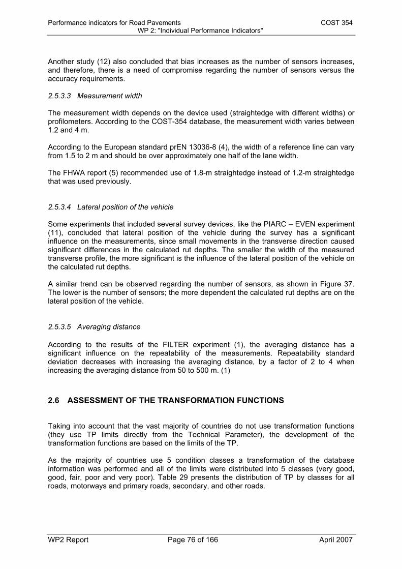
Performance indicators for Road Pavements COST 354 WP 2: "Individual Performance Indicators"
WP2 Report Page 76 of 166 April 2007
Another study (12) also concluded that bias increases as the number of sensors increases, and therefore, there is a need of compromise regarding the number of sensors versus the accuracy requirements. 2.5.3.3 Measurement width The measurement width depends on the device used (straightedge with different widths) or profilometers. According to the COST-354 database, the measurement width varies between 1.2 and 4 m. According to the European standard prEN 13036-8 (4), the width of a reference line can vary from 1.5 to 2 m and should be over approximately one half of the lane width. The FHWA report (5) recommended use of 1.8-m straightedge instead of 1.2-m straightedge that was used previously. 2.5.3.4 Lateral position of the vehicle Some experiments that included several survey devices, like the PIARC – EVEN experiment (11), concluded that lateral position of the vehicle during the survey has a significant influence on the measurements, since small movements in the transverse direction caused significant differences in the calculated rut depths. The smaller the width of the measured transverse profile, the more significant is the influence of the lateral position of the vehicle on the calculated rut depths. A similar trend can be observed regarding the number of sensors, as shown in Figure 37. The lower is the number of sensors; the more dependent the calculated rut depths are on the lateral position of the vehicle. 2.5.3.5 Averaging distance According to the results of the FILTER experiment (1), the averaging distance has a significant influence on the repeatability of the measurements. Repeatability standard deviation decreases with increasing the averaging distance, by a factor of 2 to 4 when increasing the averaging distance from 50 to 500 m. (1)
2.6 ASSESSMENT OF THE TRANSFORMATION FUNCTIONS
Taking into account that the vast majority of countries do not use transformation functions (they use TP limits directly from the Technical Parameter), the development of the transformation functions are based on the limits of the TP. As the majority of countries use 5 condition classes a transformation of the database information was performed and all of the limits were distributed into 5 classes (very good, good, fair, poor and very poor). Table 29 presents the distribution of TP by classes for all roads, motorways and primary roads, secondary, and other roads.

Performance indicators for Road Pavements COST 354 WP 2: "Individual Performance Indicators"
WP2 Report Page 77 of 166 April 2007
Table 29: TP Rut Depth limits (mm) for all road functional classes Country Class Very good Very poor
AUSTRIA (AT) M < 2.9 2.9 to 7.6 7.6 to 14.3 14.3 to 20 > 20 AUSTRIA (AT) P < 3.6 3.6 to 10.7 10.7 to 17.9 17.9 to 25 > 25
BELGIUM (BE) 1 M, P & S < 4 4 to 12 12 to 16 16 to 32 > 32 BELGIUM (BE) 2 M, P & S < 4 4 to 8 8 to 12 12 to 16 > 16
SWITZERLAND (CH) M < 4 4 to 6 6 to 9 9 to 12 12 to 16 SWITZERLAND (CH) P < 5 5 to 8 8 to 12 12 to 18 18 to 27 SWITZERLAND (CH) S < 6 6 to 10 10 to 16 16 to 24 > 24
CZECH REP. (CZ) M & P < 6 6 to 11 11 to 16 16 to 22 > 22 CZECH REP. (CZ) S & O < 8 8 to 15 15 to 25 25 to 36 > 36 GERMANY (DE) M < 4 4 to 10 10 to 20 > 20 GERMANY (DE) P < 4 4 to 15 15 to 25 > 25 GERMANY (DE) S < 4 4 to 20 20 to 30 > 30 CROATIA (HR) M & P < 8 8 to 15 15 to 20 > 20
HUNGARY (HU) M , P & S < 5 5 to 8 8 to 12 12 to 18 > 18 SLOVENIA (SI) M < 6 6 to 10 10 to 14 14 to 18 > 18 SLOVENIA (SI) P < 8 8 to 12 12 to 16 16 to 20 > 20
UNITED KINGDOM (UK) M & P < 6 6 to 11 11 to 20 > 20 UNITED STATES (US) M & P < 4.4 4.4 to 8.9 8.9 to 13.3 13.3 to 17.8 > 17.8
The results are shown in Figure 38 together with the calculated average transformation function.
5.2
9.9
21.9
14.9
0
5
10
15
20
25
30
35
40
Very good Good Fair Poor
Category Class
Rut
Dep
th (m
m)
Very Good FairGood Poor Very Poor
Figure 38: Limits for Technical parameter Rut Depth on Motorways and Other Primary
Roads
To be able to propose the unified transformation function from TP Rut Depth to PI Rutting (PI_R), the average TP limits were calculated. These are presented in Table 30, Table 31 and Table 32 for all roads, motorways and primary roads, and secondary roads respectively.
Table 30: Average TP Rut Depth limits and corresponding PI limits for all roads

Performance indicators for Road Pavements COST 354 WP 2: "Individual Performance Indicators"
WP2 Report Page 78 of 166 April 2007
Condition class name TP limits (mm, average)
PI_R limits
0 to 5.0 0 ≤ PI_R < 1 5.0 to 9.4 1 ≤ PI_R < 2
9.4 to 13.8 2 ≤ PI_R < 3 13.8 to 20.3 3 ≤ PI_R < 4
Very good
Very poor > 20.3 4 ≤ PI_R < 5
Table 31: Average TP Rut Depth limits and corresponding PI_R limits for motorways and primary roads
Condition class name TP limits (mm, average) PI_R limits 0 to 5.2 0 ≤ PI_R < 1
5.2 to 9.9 1 ≤ PI_R < 2 9.9 to 14.9 2 ≤ PI_R < 3 14.9 to 21.9 3 ≤ PI_R < 4
Very good
Very poor > 21.9 4 ≤ PI_R < 5
Table 32: Average TP Rut Depth limits and corresponding PI_R limits for secondary roads
Condition class name TP limits (mm, average) PI_R limits 0 to 5.2 0 ≤ PI_R < 1
5.2 to 10.6 1 ≤ PI_R < 2 10.6 to 16.8 2 ≤ PI_R < 3 16.8 to 26.0 3 ≤ PI_R < 4
Very good
Very poor > 26.0 4 ≤ PI_R < 5
The transformation functions were obtained by regression as second order polynomials and are shown graphically in Figure 39: For all road classes: PI_R = -0.0016·RD2 + 0.2187·RD for RD < 29.0 mm PI_R = 5 for RD ≥ 29.0 mm For motorways and primary roads: PI_R = -0.0015·RD2 + 0.2291·RD for RD < 26.4 mm PI_R = 5 for RD ≥ 26.4 mm For secondary and local roads:

Performance indicators for Road Pavements COST 354 WP 2: "Individual Performance Indicators"
WP2 Report Page 79 of 166 April 2007
PI_R = -0.0023·RD2 + 0.2142·RD for RD < 46.9 mm PI_R = 5 for RD ≥ 46.9 mm
0
5.2
29
0
26.4
0
21.9
14.9
9.9
13.8
20.3
5
9.4
16.8
10.6
5.2
26
0
0.5
1
1.5
2
2.5
3
3.5
4
4.5
5
0 2.5 5 7.5 10 12.5 15 17.5 20 22.5 25 27.5 30
TP limits (mm)
PI li
mits
All
M&P
S
Figure 39: Average transformation function from TP Rut Depth to PI Rutting
However, some issues that may limit the validity of the proposed functions should be mentioned at this point. First, the sample used for derivation of transformation functions was relatively small (less than 20 records). Secondly, the analysis was based on technical parameter limits, regardless of the algorithm used for data processing. Some countries use straightedge algorithm with different lengths, and some use wire line algorithm. There is a question of impact of the used algorithm on TP values and its importance on the pavement management level data and corresponding transformation functions. Finally, the transformation functions were derived from the average values for TP limits between some categories. There was some subjectivity in assigning these values, particularly when there is difference in the number of classes used. On the other side, comparison with rut depth limits in the AASHTO PP38-00 provisional standard (13) (Table 33) and in ASTM D6433-03 standard (14) shows that used TP limits agree reasonably well with the values used in these two standards.
Table 33: The average rut depth limits for different classifications, according to AASHTO PP 38-00

Performance indicators for Road Pavements COST 354 WP 2: "Individual Performance Indicators"
WP2 Report Page 80 of 166 April 2007
Number of classes Level Two classes Three classes Four classes 1 < 12.5 mm < 12.5 mm < 5 mm 2 ≥ 12.5 mm ≥ 12.5 mm and < 25 mm ≥ 5 mm and < 10 mm 3 ≥ 25 mm ≥ 10 mm and < 25 mm 4 ≥ 25 mm
ASTM standard D6433-03 – Standard Practice for Roads and Parking Lots Pavement Condition Index Surveys (14) defines three severity levels according to the mean rut depth (MRD) measured by straightedge:
• Low (MRD equals 6 to 13 mm) • Medium (MRD equals 13 to 25 mm) • High (MRD greater than 25 mm)

Performance indicators for Road Pavements COST 354 WP 2: "Individual Performance Indicators"
WP2 Report Page 81 of 166 April 2007
2.7 CORRELATION BETWEEN THE SELECTED INDICATOR AND OTHER
USED INDICATORS
Comparison between different transverse evenness technical parameters is not simple since it includes three types of indices. This issue is even more complicated since although the COST-354 database contains relatively sufficient data for the TP Rut Depth there is not enough data for the other technical parameters used to describe transverse evenness. Only Germany provided transformation functions for TP Water Height. Therefore, in this chapter no correlations between the selected indicator (rut depth) and the other indicators are provided.

Performance indicators for Road Pavements COST 354 WP 2: "Individual Performance Indicators"
WP2 Report Page 82 of 166 April 2007
2.8 REFERENCES
1. Descornet G., Berlemont B., Martin J-M. FILTER – Analysis of Transverse Measurements,
FEHRL Technical Paper 2000/01, FEHRL, 2000.
2. Willet M., Magnusson G., Ferne B.W. FILTER – Theoretical Study of Indices, FEHRL Technical Paper 2000/02, FEHRL, 2000.
3. Lundberg T., Sjogren L.. Quantification of road surface monitoring services in Sweden, 1996 – 2000, VTI Notat 38A – 2004.
4. prEN 13036-8 (2006) – Road and Airfield Surface Characteristics – Test Methods – Part 8: Transverse unevenness and irregularities, definitions, methods of evaluation and reporting, draft European standard
5. Characterization of Transverse Profiles, FHWA Report FHWA-RD-01-024, April 2001.
6. prEN 13036-6 (2006) – Road and Airfield Surface Characteristics – Test Methods – Part 6: Measurement of Transverse and Longitudinal Profiles in the Evenness and Megatexture Wavelength Ranges, draft European standard
7. EN 13036-7 (2003) – Road and Airfield Surface Characteristics – Test Methods – Part 7: Irregularity Measurement of Pavement Courses – The Straightedge Test, European standard
8. ASTM standard E1703/E1703M-95 (2005) – Standard Test Method for Measuring Rut-Depth of Pavement Surfaces Using a Straightedge, ASTM, 2005.
9. AASHTO provisional standard PP 32-96 (2000) – Standard Practice for Measuring Pavement Profile Using a Dipstick®
10. ASTM standard E2133-03 – Standard Test Method for Using a Rolling Inclinometer to Measure Longitudinal and Transverse Profiles of a Traveled Surface
11. International Experiment to Harmonize Longitudinal and Transverse Profile Measurement and Reporting Procedures, PIARC, 2000.
12. Mallela R., Wang H. Harmonizing automated rut depth measurements – Stage 2, Research Report 277, Land Transport New Zealand, 2006.
13. AASHTO provisional standard PP 38-00 – Standard Practice for Determining Maximum Rut Depth in Asphalt Pavements
14. ASTM standard D6433-03 – Standard Practice for Roads and Parking Lots Pavement Condition Index Surveys
15. NCHRP Synthesis 334: Automated Pavement Distress Collection Techniques, Transportation Research Board, Washington DC, USA, 2004.
16. Distress Identification Manual for the Long-Term Pavement Performance Project, FHWA-RD-03-031, FHWA, Pavement Performance Division, McLean, VA, June 2003.

Performance indicators for Road Pavements COST 354 WP 2: "Individual Performance Indicators"
WP2 Report Page 83 of 166 April 2007
SECTION 3: MACRO TEXTURE
Surface texture is primarily associated with safety conditions and user comfort but also road deterioration. In terms of safety, texture directly affects how well tyres stick to the pavement in moist or wet conditions, and thereby indirectly affects skid resistance. Texture is also associated with noise emission caused by traffic. From a pavement management perspective, texture depth is important since it can be controlled by maintenance activities and can even trigger maintenance treatments. Texture depth arises from the angularities in the materials that make up the road surface. Texture can be characterized by measuring a profile in the adequate wavelength band and calculate a proper index, as shown in Figure 40. There are three types of texture, classified according to profile wavelength:
• Microtexture can be described by the roughness of the aggregate itself. It provides the adhesion between the rubber tyres and the road surface. Microtexture is represented by wavelengths of < 0,5 mm wavelength.
• Macrotexture is associated with the coarser element formed by aggregate particles and the particle distribution. It is represented by wavelengths of 0,5 mm – 50 mm.
• Megatexture is associated with deficiencies of the pavement surface, and has a negative impact on safety and comfort. Megatexture is represented by wavelengths of 50 mm-0.5 m.
Surface Texture profile Microtexture Macrotexture
1
2
3
4
Figure 40: Description of texture At the moment there are no systems capable of measuring microtexture profiles at highway speeds. Therefore, microtexture is evaluated by using pavement friction at low speeds as a surrogate. As such, this section of the report will only look into the performance indicators which handle the macrotexture (in the rest of the section called “texture”).
3.1 TEXTURE INDICATORS FROM THE COST 354 DATABASE
From the total of 22 countries represented in the questionnaire used by WG2, 10 countries reported that they use texture measurement (45%). 4 of the 10 countries answered 2 questionnaires1.
1 As far as Italy is concerned Motorways Authorities run routine texture measurements and a national standard is available but this was not included in the database as it is not used by the respondent Road Authority. To avoid confusions and inconsistency of data this information will not be added in WG2 work.

Performance indicators for Road Pavements COST 354 WP 2: "Individual Performance Indicators"
WP2 Report Page 84 of 166 April 2007
Table 34: Number of countries and records referred to macrotexture performance indicator
COUNTRY No. of Texture Records
AUSTRIA 1 CZECH REPUBLIC 2
DENMARK 1 FRANCE 2
HUNGARY 1 SERBIA AND MONTENEGRO 1
SLOVENIA 2 SPAIN 2
SWEDEN 1 UNITED KINGDOM 1
10 14 Total number of records in the database: 14 Total number of countries: 10 out of 22 possible (45%)
3.1.1 General information According to the database, two general measuring principles are used to indicate the texture. The principles are:
1. Volumetric method (Sand Patch) 2. Laser method
The distribution in use between one method or the other is shown in Table 35.
Table 35: Description of macrotexture technical parameters from the COST-354 database
COUNTRY Technical Parameter NAME MEASURING PRINCIPLE Laser method AUSTRIA Mean profile depth Laser CROATIA(*) Texture depth Laser DENMARK Mean profile depth Laser SPAIN 1 Mean profile depth Laser SWEDEN Mean profile depth Laser CZECH REPUBLIC 1 Texture depth Laser CZECH REPUBLIC 2 Texture depth Laser FRANCE Sand patch value Laser SLOVENIA 1 Mean profile depth Laser UNITED KINGDOM Mean profile depth Laser Volumetric method CROATIA(*) Mean profile depth Sand Patch SLOVENIA 2 Mean profile depth Sand patch SPAIN 2 Mean profile depth Sand patch SERBIA AND MONTENEGRO Mean profile depth Sand patch Answers which is not usable HUNGARY Mean profile depth Laser (*) information not in the COST database used for the analysis, obtained during the WG2 work. It is not included in the following distribution analyses.

Performance indicators for Road Pavements COST 354 WP 2: "Individual Performance Indicators"
WP2 Report Page 85 of 166 April 2007
There are a few answers which need a closer look before being taken into account. The countries which have given these answers are: Hungary, Czech Republic and France. Hungary: According to Hungary, the levels indicated in the database are based on the sand patch method and not the laser method which is indicated to be the measuring principle. Further on, the levels are not official, but determined by one person based on experience and observations. Due to this, the answers from Hungary will not be taken into account in this analysis. France: According to France, the two answers are identical. The only difference is that one is by a company on toll motorways and the other is used on national highways. The two answers can therefore be directly combined. The processing of the profile is done so that the result is comparable with the result that would have been obtained at the same location by performing a manual traditional sand patch test. In the following analysis, the two answers from France will count as one. Czech Republic: The abbreviation for the Czech Republic indicates the use of the sand patch method, but as with France, the method is done by laser. Name, description, unit and abbreviation were to be stated for each PI, as synthesised in Table 36.
Table 36: Description of macrotexture technical parameters from the COST-354 database
COUNTRY Technical ParameterNAME
Technical ParameterDESCRIPTION ABBR. MEASURING
PRINCIPLE UNIT
Laser method AUSTRIA Mean profile depth Mean profile depth MPD Laser mm CROATIA(*) Texture depth Mean texture depth MTD Laser mm CZECH REPUBLIC 1 Texture depth Mean texture depth MTD Laser mm
CZECH REPUBLIC 2 Texture depth Mean texture depth MTD Laser mm
DENMARK Mean profile depth Texture value MPD Laser mm FRANCE Sand patch value Sand patch HS/SPV Laser -
SLOVENIA 1 Mean profile depth Sensor Measured Texture Depth SMTD Laser mm
SPAIN 1 Mean profile depth Macrotexture MPD Laser mm SWEDEN Mean profile depth Macrotexture MPD Laser mm UNITED KINGDOM Mean profile depth Sensor Measured
Texture Depth SMTD Laser mm
Volumetric method (Sand Patch) CROATIA(*) Mean profile depth Texture Depth TD Sand patch mm SLOVENIA 2 Mean profile depth Macrotexture MTD Sand patch mm SPAIN 2 Mean texture depth Macrotexture MTD Sand patch mm SERBIA AND MONTENEGRO Mean profile depth Texture Depth DT Sand patch mm (*) information not in the COST database used for the analysis, obtained during the WG2 work. It is not included in the following distribution analyses.
As Table 36 shows, 10 of the answers use laser equipment for measuring texture. Only 3 indicate use of the volumetric method1. The majority of the responders use the name “Mean Profile Depth” for this technical parameter. One country uses the name texture depth, and one the name sand patch.
1 Without considering Croatia, added later in the work
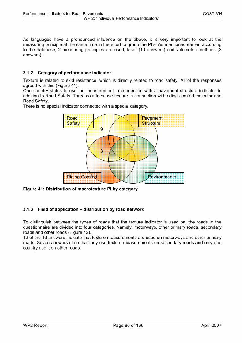
Performance indicators for Road Pavements COST 354 WP 2: "Individual Performance Indicators"
WP2 Report Page 86 of 166 April 2007
As languages have a pronounced influence on the above, it is very important to look at the measuring principle at the same time in the effort to group the PI’s. As mentioned earlier, according to the database, 2 measuring principles are used; laser (10 answers) and volumetric methods (3 answers).
3.1.2 Category of performance indicator Texture is related to skid resistance, which is directly related to road safety. All of the responses agreed with this (Figure 41). One country states to use the measurement in connection with a pavement structure indicator in addition to Road Safety. Three countries use texture in connection with riding comfort indicator and Road Safety. There is no special indicator connected with a special category.
Pavement Structure
Environmental Riding Comfort
Road Safety
9
3
1
Figure 41: Distribution of macrotexture PI by category
3.1.3 Field of application – distribution by road network To distinguish between the types of roads that the texture indicator is used on, the roads in the questionnaire are divided into four categories. Namely, motorways, other primary roads, secondary roads and other roads (Figure 42). 12 of the 13 answers indicate that texture measurements are used on motorways and other primary roads. Seven answers state that they use texture measurements on secondary roads and only one country use it on other roads.

Performance indicators for Road Pavements COST 354 WP 2: "Individual Performance Indicators"
WP2 Report Page 87 of 166 April 2007
Other primary roads
Other Roads
Secondary Roads
Motorways
6
1
6
Figure 42: Distribution of macrotexture PI by road network
3.1.4 Distribution by Level of Application There is a distinct difference between which indicators (and equipment) are used on network and which are used on project levels. From the 13 answers, only three indicators are used on project level (Figure 43). The indicator used for project levels is the volumetric method (sand patch) or MTD. The 10 remaining answers all use a laser method. 7 answers use their indicators on network level alone, 3 use their indicators on network and project level.
Project Network
7 33
Figure 43: Distribution of macrotexture PI by Level of Application
3.1.5 Distribution by Pavement Type The answers indicate that texture measurements are applied on both flexible and rigid pavements (bituminous and concrete) with 4 indicators used only for bituminous pavements (Figure 44).
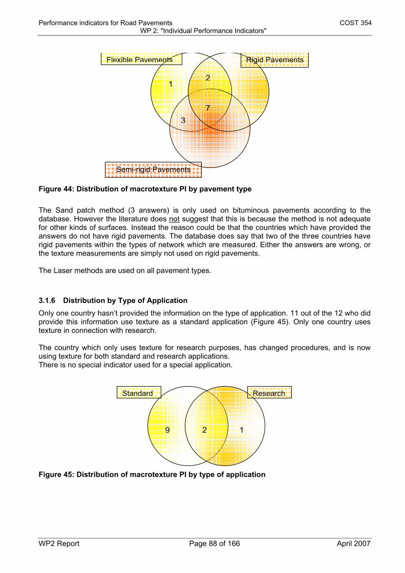
Performance indicators for Road Pavements COST 354 WP 2: "Individual Performance Indicators"
WP2 Report Page 88 of 166 April 2007
Rigid Pavements
Semi-rigid Pavements
Flexible Pavements
12
73
Figure 44: Distribution of macrotexture PI by pavement type The Sand patch method (3 answers) is only used on bituminous pavements according to the database. However the literature does not suggest that this is because the method is not adequate for other kinds of surfaces. Instead the reason could be that the countries which have provided the answers do not have rigid pavements. The database does say that two of the three countries have rigid pavements within the types of network which are measured. Either the answers are wrong, or the texture measurements are simply not used on rigid pavements. The Laser methods are used on all pavement types.
3.1.6 Distribution by Type of Application Only one country hasn’t provided the information on the type of application. 11 out of the 12 who did provide this information use texture as a standard application (Figure 45). Only one country uses texture in connection with research. The country which only uses texture for research purposes, has changed procedures, and is now using texture for both standard and research applications. There is no special indicator used for a special application.
ResearchStandard
9 12
Figure 45: Distribution of macrotexture PI by type of application

Performance indicators for Road Pavements COST 354 WP 2: "Individual Performance Indicators"
WP2 Report Page 89 of 166 April 2007
3.1.7 Standardization As it can be seen from Table 37, 7 of the countries (not considering Croatia, added later) have based their technical parameter on a national standard. 3 countries have based their technical parameters on technical specifications, and only 4 countries have based their technical specifications on the ISO standard. Austria has indicated two standards. The physical measurement is done according to a national standard, but is calculated according to the ISO standard.
Table 37: Standards and specifications used for macrotexture performance indicators
COUNTRY STANDARD USED TO COLLECT THE TP
AUSTRIA National Standard/ISO-standard
CROATIA(*) National Standard/EN Standard
CZECH REPUBLIC 1 National Standard
CZECH REPUBLIC 2 National Standard
DENMARK ISO-Standard
FRANCE 1 National Standard
FRANCE 2 National Standard
SERBIA AND MONTENEGRO National Standard
SLOVENIA 1 Technical Specification
SLOVENIA 2 Technical Specification
SPAIN 1 ISO-Standard
SPAIN 2 National Standard
SWEDEN ISO-Standard
UNITED KINGDOM Technical Specification (*) information not in the COST database used for the analysis, obtained during the WG2 work. It is not included in the following distribution analyses.
3.1.8 Measuring principle As mentioned earlier, two types of measuring principles are used for the characterization of macrotexture: the volumetric (Sand Patch) and the laser method. Volumetric (Sand Patch) method: The Sand Patch method is well known. Traditionally, the Sand Patch Method has been used to estimate performance indicator Mean Texture Depth, or MTD. This method involves applying a determined amount of sand or glass beads onto a textured surface, and spreading the sand outward into a circle, as described by EN standard 13036-1 (1). The more texture a surface contains, the smaller the circle that is created.

Performance indicators for Road Pavements COST 354 WP 2: "Individual Performance Indicators"
WP2 Report Page 90 of 166 April 2007
Laser method: Measuring texture using lasers is independent of the operating speed, as it is possible to perform the tests at speeds from a few km/h to traffic speed. Even though there are several different measuring devices which combine texture measurements with either longitudinal evenness or friction (e.g. Aran, RAV, Roadstar, Roar, RST and Rugolaser) the measurements are done in identical ways, but with small differences in the build-up of the equipment. Generally the devices employ lasers pointing at one or more spots on the pavement surface, often in both wheel tracks, to measure texture. The measurements are carried out in individual profiles (parallel profiles can be measured in a single road segment). Each profile consists of a number of levelings which are conducted at a certain interval. In 2004, in connection with the Hermes project (2), texture measurements with participating devices were carried out. This gave an opportunity to evaluate the reproducibility of the measurement of MPD by different devices claimed to comply with EN-ISO 13473-1 (3). The end result showed the standard deviation of reproducibility between pairs of devices to have an overall value of 0,11 mm. Depending on equipment and software, the measurements are reported in terms of either the “mean profile depth” (MPD) or as the “sensor measured texture depth” (SMTD). SMTD, or the Sensor Measured Texture Depth is equivalent to the root mean square deviation of the amplitude of the texture about a notional datum. SMTD results cannot be compared directly with the texture depth figures obtained by Sand Patch texture depth or MPD testing. The mean profile (MPD) depth is a statistic computed by analyzing segments of 100 mm of the collected data, see Figure 46. After dividing each segment in half, the average of the highest profile peaks in each half is computed. The MPD is then computed as the average of all individual segment peak averages. The standard describing calculation and reporting of MPD gives options that can result in different results. This has to be considered. To avoid this, the standard is now under revision. According to the standard, MPD can be used to estimate MTD values (“sand patch”). When MPD is used to predict MTD, the result is referred to as an estimated texture depth (ETD)
3.2 COMPLEMENTARY INFORMATION DERIVED FROM LITERATURE
Another option available is a Circular Texture Meter, or CTM. Like the Sand Patch, this technique involves taking measurements at discrete locations along the pavement. The CTM uses a spot laser mounted on a rotating arm. Once in place, the unit triggers a computer that rotates the arm and measures texture height for one complete revolution. The resulting trace can then be used to estimate the MTD.
3.3 EVALUATION AND SELECTION OF THE MOST USED INDIVIDUAL PERFORMANCE INDICATORS;
The questionnaire clearly states that two types of methods are used; volume metric and laser. From these measuring methods 3 performance indicators can be calculated and used; MTD, MPD and SMTD. A series of criteria (previously presented in section 1.3) has been listed for the selection of the individual performance to be used. The criteria and comments are as follows:
• The indicator should be described in an European or International standard: Two out of three texture performance indicators are described in international standards: - MPD: EN-ISO standards 13473 and ASTM E 1845-96. - MTD: ISO 10844:1994, EN 13036-1, ASTM E965-96.
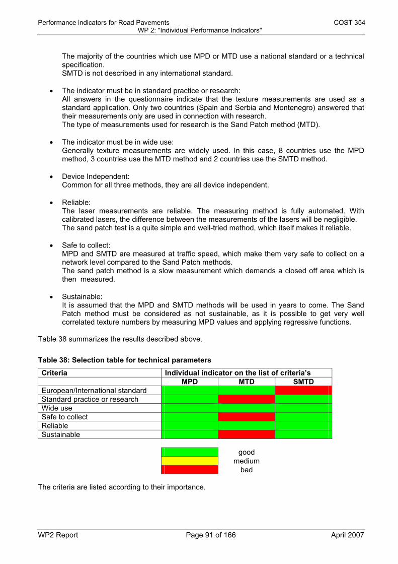
Performance indicators for Road Pavements COST 354 WP 2: "Individual Performance Indicators"
WP2 Report Page 91 of 166 April 2007
The majority of the countries which use MPD or MTD use a national standard or a technical specification. SMTD is not described in any international standard.
• The indicator must be in standard practice or research:
All answers in the questionnaire indicate that the texture measurements are used as a standard application. Only two countries (Spain and Serbia and Montenegro) answered that their measurements only are used in connection with research. The type of measurements used for research is the Sand Patch method (MTD).
• The indicator must be in wide use:
Generally texture measurements are widely used. In this case, 8 countries use the MPD method, 3 countries use the MTD method and 2 countries use the SMTD method.
• Device Independent:
Common for all three methods, they are all device independent.
• Reliable: The laser measurements are reliable. The measuring method is fully automated. With calibrated lasers, the difference between the measurements of the lasers will be negligible. The sand patch test is a quite simple and well-tried method, which itself makes it reliable.
• Safe to collect:
MPD and SMTD are measured at traffic speed, which make them very safe to collect on a network level compared to the Sand Patch methods. The sand patch method is a slow measurement which demands a closed off area which is then measured.
• Sustainable:
It is assumed that the MPD and SMTD methods will be used in years to come. The Sand Patch method must be considered as not sustainable, as it is possible to get very well correlated texture numbers by measuring MPD values and applying regressive functions.
Table 38 summarizes the results described above.
Table 38: Selection table for technical parameters
Criteria Individual indicator on the list of criteria’s MPD MTD SMTD European/International standard Standard practice or research Wide use Safe to collect Reliable Sustainable good medium bad
The criteria are listed according to their importance.

Performance indicators for Road Pavements COST 354 WP 2: "Individual Performance Indicators"
WP2 Report Page 92 of 166 April 2007
There is no doubt, that the laser methods used for measuring texture are the methods to prefer. These methods can be measured at traffic speed, and are therefore safe to collect. They are widely used as a standard practice and they are both reliable and sustainable. SMTD does have a range of positive qualities, unfortunately SMTD is not described in any European or International standard. As the MPD calculation is described in an EN-ISO standard, it was decided that the individual selected performance indicator for macrotexture would be the MPD.
3.4 PROTOCOLS AND TEST METHODS FOR MEASURING THE PROPOSED INDIVIDUAL INDICATOR
As mentioned, the MPD calculation is described in detail in EN-ISO standard 13473-1 (3). Based on measurement done by laser, the MPD can be calculated easily as shown in Figure 46. The base line is in the EN-ISO standard and has been set to 100 mm.
Figure 46: Calculation of the Mean Profile Depth (MPD)
3.5 ASSESSMENT OF THE TRANSFORMATION FUNCTIONS
The aim of this section is to transform the MPD technical parameter (with the units of a length) to a unitless PI on a 0 to 5 scale. To achieve this, the results from both the transformation functions available in the database and the “levels” (thresholds, warning, acceptance and target) proposed by the different responders have been considered.

Performance indicators for Road Pavements COST 354 WP 2: "Individual Performance Indicators"
WP2 Report Page 93 of 166 April 2007
Levels The questionnaire provides only a few answers where levels have been indicated by a country1. The levels indicated in the database are shown in Table 39:
Table 39: Levels from the database
THRESHOLD WARNING ACCEPTANCE TARGET COUNTRY NAME Performance
indicator TP INDEX TP INDEX TP INDEX TP INDEX CZECH
REPUBLIC 1
Texture depthMPD MPD 0,54 0,64
CZECH REPUBLIC
2
Texture depthMPD MPD 0,44 0,54
FRANCE 1 Sand patch
value MPD
MPD 40 60
France has indicated that they use 2 levels, 40 as the threshold level and 60 as acceptance level. The processing of the profile is done so that the result is comparable with the result that would have been obtained at the same location by performing a traditional manual sand patch test. Because it is not known which transformation function is used in the process, it is not possible to take the limits into account when generating the general performance indicator index. Performance index Sweden forwarded the levels at a moment where it wasn’t possible to put it into the database. The contribution to the database with the conversion to the 5 step performance index is as shown in Table 40.
Table 40: Macrotexture levels adopted by Sweden (not in the database)
MDP interval
90 - 110 km/h Motorways and other primary roads
70 km/h Secondary roads
0 - 0,3 Not suitable/very poor Not suitable/very poor0,31 - 0,5 Not suitable/very poor Bad/poor 0,51 - 0,7 Bad/poor Ok/very good 0,71 - 1,0 Ok/very good Acceptable/good 1,01 - 1,50 Ok/very good Bad/poor 1,51 - 2,00 Acceptable/good Bad/poor 2,01 - Bad/poor Not suitable/very poor
Sweden has not specified threshold or warning levels. The Swedish intervals/limits are not in use but are under consideration. As mentioned above, The Czech Republic has specified the limits which they use, shown in Table 41. 1 Croatia actually has acceptance thresholds but this information was gathered after the analysis was completed and couldn’t be considered. It might be included in later revisions of the database.

Performance indicators for Road Pavements COST 354 WP 2: "Individual Performance Indicators"
WP2 Report Page 94 of 166 April 2007
Table 41: macrotexture limits indicated by Czech Republic
Czech Rep. Czech Rep. Motorways & other primary roads
Secondary & others roads
1 Very good 0,89 0,79
2 Good 0,74 0,64
3 Fair 0,64 0,54
4 Poor 0,54 0,44
5 Very poor
Correlation The following diagrams illustrate the result of the analysis of the questionnaires concerning texture. The diagrams have been divided into 2 groups; motorways and Other Primary Roads (Figure 47), and Secondary Roads (Figure 48).
Primary and other roads
y = 0.1886x + 0.2591
0
0.1
0.2
0.3
0.4
0.5
0.6
0.7
0.8
0.9
1
PI_macrotexture
MPD
(mm
) SECZMeanLinjär (Mean)
Very poor Poor Fair Good Very Good
Linear (Mean)
Figure 47: macrotexture levels for motorways and other primary roads

Performance indicators for Road Pavements COST 354 WP 2: "Individual Performance Indicators"
WP2 Report Page 95 of 166 April 2007
Secondary roads
y = 0.1446x + 0.2829
0
0.1
0.2
0.3
0.4
0.5
0.6
0.7
0.8
0.9
1
PI_macrotexture
MP
D(m
m) CZ secondary roads
Linjär (CZ secondaryroads)
Very poor
Very poor Poor Fair Good Very Good
Linear (CZ secondary roads)
Figure 48: macrotexture levels for secondary roads It should be noted that, given the very limited amount of data, the information from two countries will be used as a basis for a common expression of the macrotexture PI that will then be used for the following activities in the COST 354 action. More data concerning levels and limits should be collected to improve the quality of the macrotexture PI definition. The transformation functions between the MPD measurements (in mm) and the macrotexture performance index (PI_T) that will be used for the COST 354 action are: For motorways and primary roads PI_T =6.6-5.3xMPD (average of SE and CZ data) For secondary roads PI_T=7.0-6.9xMPD (only CZ data used) with MPD in mm in both equations.
3.6 CORRELATION BETWEEN THE SELECTED INDICATOR AND OTHER USED INDICATORS
Correlation between MPD and other texture PI’s from the database MPD - MTD: To be able to correlate MPD with a mean texture depth the EN-ISO standard has indicated a conversion equation from MPD to ETD (which is the estimation of he MTD):
ETD=0.2+0.8XMPD However this is now under consideration and a one to one conversion is being discussed.

Performance indicators for Road Pavements COST 354 WP 2: "Individual Performance Indicators"
WP2 Report Page 96 of 166 April 2007
Had there been any limits and/or levels given in connection with the MTD indicator, they could have been used to help create a more accurate general performance indicator index (PI). Unfortunately no countries which use MTD have specified any limits and/or levels. MPD - SMTD: Because of the difference in calculating MPD and SMTD from the measured profile, a correlation of the two is not possible. The result is that the limits given by U.K and Slovenia are not included in the analysis.
3.7 REFERENCES
1. EN 13036-1 (2002) – Road and airfield surface characteristics. Test methods. Measurement
of pavement surface macrotexture depth using a volumetric patch technique 2. HERMES – “Harmonization of European Routine and research Measuring Equipment for
Skid Resistance”, FEHRL Project (www.fehrl.org) 3. EN-ISO 13473-1 “Characterisation of pavement texture by use of surface profiles - Part 1:
Determination of Mean Profile Depth”

Performance indicators for Road Pavements COST 354 WP 2: "Individual Performance Indicators"
WP2 Report Page 97 of 166 April 2007
SECTION 4: FRICTION
4.1 SKID RESISTANCE INDICATORS FROM THE COST 354 DATABASE
The records included in the COST 354 database regarding skid resistance PI have provided very valuable information as they correspond to almost all of the Countries included in the Action. The following sections report about the analysis carried out from this information, to try to propose a suitable indicator about skid resistance, and to determine the conclusions that can be reached from the information provided. Among the 22 countries represented in the database, 20 (90 %), filled in the skid resistance group criteria. But the number of questionnaires analyzed is slightly higher (22) because France and Belgium each reported two. The last column of Table 42 shows the number of records concerning skid resistance. It doesn’t fit with the number of questionnaires. The reason is that Czech Republic gave 4 answers and Croatia reported 2 answers. It means that the total number of records analyzed here is 26.
Table 42: Number of countries, questionnaires and records referred to skid resistance performance indicator
COUNTRY TOTAL SKID RESISTANCE Nº QUESTIONNAIRES Nº QUESTIONNAIRES Nº RECORDS AUSTRIA 1 1 1 BELGIUM 2 2 2 CROATIA 1 1 2 CZECH REPUBLIC 1 1 4 DENMARK 1 1 1 FINLAND 1 FRANCE 2 2 2 GERMANY 1 1 1 GREECE 1 1 1 HUNGARY 1 1 1 ITALY 1 1 1 NETHERLANDS 1 1 1 NORWAY 1 1 1 POLAND 1 1 1 PORTUGAL 1 1 1 SERVIA AND MONTENEGRO 1 1 1 SLOVENIA 1 1 1 SPAIN 1 1 1 SWEDEN 1 1 1 SWITZERLAND 1 1 1 UNITED KINGDOM 1 1 1 UNITED STATES OF AMERICA 1

Performance indicators for Road Pavements COST 354 WP 2: "Individual Performance Indicators"
WP2 Report Page 98 of 166 April 2007
COUNTRY TOTAL SKID RESISTANCE 22 24 22 26
4.1.1 General information Some questions about the skid resistance technical parameter are included in the COST 354 database, they are: • the name, • the description, • the abbreviation, • the unit. As the abbreviation is not the same in all of the countries (mainly due to both the language and the different words that can describe the same parameter), it hasn’t been included in this analysis, which is based on the meaning of the technical parameter. The situation is sometimes the same for the description. In the case of the skid resistance technical parameters, it is very important to take into account the measuring principle of the device used to collect the data, because it gives very valuable information about the possibility of making groups of the same technical parameter used in different Countries. By doing so, it seems that the terms friction coefficient and sideway force refer to the same technical parameter. Table 43 includes the description of the technical parameters reported in the database.
Table 43: Description of skid resistance technical parameters from the COST-354 database
COUNTRY NAME DESCRIPTION UNIT
AUSTRIA FRICTION COEFFICIENT FRICTION VALUE
BELGIUM 1 SIDEWAY FORCE SIDEWAY FORCE
BELGIUM 2 FRICTION COEFFICIENT TRANSVERSE FRICTION COEFFICIENT
CROATIA 1 FRICTION COEFFICIENT SRT
CROATIA 2 FRICTION COEFFICIENT GRIP TESTER NUMBER
CZECH REPUBLIC 1 TEXTURE DEPTH MEAN TEXTURE DEPTH mm
CZECH REPUBLIC 2 TEXTURE DEPTH MEAN TEXTURE DEPTH mm
CZECH REPUBLIC 3 FRICTION COEFFICIENT ROUGHNESS
CZECH REPUBLIC 4 FRICTION COEFFICIENT ROUGHNESS
DENMARK FRICTION COEFFICIENT FRICTION VALUE
FRANCE 1 FRICTION COEFFICIENT TRANSVERSE FRICTION COEFFICIENT
FRANCE 2 FRICTION COEFFICIENT TRANSVERSE FRICTION COEFFICIENT
GERMANY FRICTION COEFFICIENT FRICTION VALUE
GREECE FRICTION COEFFICIENT SKID RESISTANCE
HUNGARY MICRO ROUGHNESS MICRO ROUGHNESS INDEX
ITALY FRICTION COEFFICIENT TRANSVERSAL ADHERENCE COEFFICIENT
NETHERLANDS FRICTION COEFFICIENT FRICTION VALUE
NORWAY FRICTION COEFFICIENT FRICTION COEFFICIENT
POLAND FRICTION COEFFICIENT FRICTION COEFFICIENT
PORTUGAL FRICTION COEFFICIENT SKID RESISTANCE OTHER
SERVIA AND MONTENEGRO FRICTION COEFFICIENT SKID RESISTANCE TEST
SLOVENIA FRICTION COEFFICIENT SKID RESISTANCE COEFFICIENT
SPAIN FRICTION COEFFICIENT SIDEWAY FORCE FRICTION %
SWEDEN FRICTION COEFFICIENT FRICTION COEFFICIENT
SWITZERLAND FRICTION COEFFICIENT FRICTION COEFFICIENT

Performance indicators for Road Pavements COST 354 WP 2: "Individual Performance Indicators"
WP2 Report Page 99 of 166 April 2007
COUNTRY NAME DESCRIPTION UNIT
UNITED KINGDOM FRICTION COEFFICIENT CHARACTERISTIC SCRIM COEFFICIENT
Some comments can be made from the records that have provided some information:
• In most of the cases with data available, the technical parameter measured is the friction coefficient.
• Macro texture appears only in two records (from the same questionnaire). The fact is that
this technical parameter has an influence on skid resistance, mainly as the speed of the vehicle increases. Perhaps only one country has included this technical parameter in the group of skid resistance PI because the database has defined another group of indicators that describes texture.
• One record indicates that the technical parameter measured is micro roughness, and it is
obtained from a laser system. Further information was provided by the country, indicating that the system is able to evaluate micro texture, although in an approximate way. It is a random type information, which is expressed as a micro texture index.
As a conclusion, three technical parameters have been identified from the COST 354 database, namely friction coefficient, macro texture and micro roughness (or micro texture). From them, the friction coefficient is the one most commonly used (88.5% of the records). One Country has provided information about macro texture together with the friction coefficient; while one Country has reported information about micro roughness.
4.1.2 Category of performance indicator All of the responses in the database include the friction performance indicators under the “safety” category.
4.1.3 Field of application – distribution by road network This issue refers to the type of roads for which the skid resistance indicators are used. In this section it is important to take into account that many of the answers are restricted to some types of roads. Therefore, the lack of information does not necessarily mean that these indicators are not used in them. If there are no mistakes, there can be two reasons for which there is no information about the use of indicators on some type of pavement: • Those pavements are not used in the Country. Therefore it should never appear in any of the
responses from that country. • The indicator is not used for some pavements. In such case, it is probable that these types of
roads are mentioned for some other PI in the questionnaire from that Country. For this reason, to have a clearer idea about this matter, it’s necessary to compare the answers related to the skid resistance indicators, with those provided by each one in the whole questionnaire. Otherwise an incorrect conclusion could be reached. From the results obtained, the analysis can be divided in three cases:

Performance indicators for Road Pavements COST 354 WP 2: "Individual Performance Indicators"
WP2 Report Page 100 of 166 April 2007
a) The skid resistance indicators are used in all the categories of roads included in the whole questionnaire of the Country (100% of agreement).
b) The skid resistance indicators are not used in, at least, one of the categories of roads included in the whole questionnaire of the Country.
c) There are data about skid resistance indicators, but there’s no information about the category of roads for which they are applied.
From the information analysed, it can be concluded that the skid resistance indicators are used in almost all the types of roads reported in the questionnaires, and they are specially applied to the main categories of roads. This conclusion comes from the results explained in more detail in the following paragraphs. Case a) In this case, the skid resistance indicators are used for all the categories of roads that appear in the questionnaire. This is the situation for 21 records from the 26 analysed (80,77%). The distribution of percentages from these 21 records, according to each category or road is included in Figure 49; while Figure 50 shows all the categories of roads covered by each answer.
Figure 49: Case a) (100% of agreement). Percentage of affirmative answers for each category
of road

Performance indicators for Road Pavements COST 354 WP 2: "Individual Performance Indicators"
WP2 Report Page 101 of 166 April 2007
Figure 50: Case a) (100% of agreement). Categories of roads covered by each record Case b) From this case, it can be concluded that, if there are no mistakes, the skid resistance indicators are not used for some roads included in the whole questionnaire of the Country. The number of records in this situation is 3: • One questionnaire provided information about motorways, other primary roads and secondary
roads, but skid resistance indicators are not used for secondary roads. • Two questionnaires provided information about all categories of roads, but skid resistance
indicators are not used for “other roads” category. The distribution of percentages, from the three records already mentioned, according to each category of road is included in Figure 51; while Figure 52 shows the categories of roads covered by each record.
Figure 51: Case b). Percentage of affirmative answers for each category of road

Performance indicators for Road Pavements COST 354 WP 2: "Individual Performance Indicators"
WP2 Report Page 102 of 166 April 2007
Figure 52: Case b) Categories of roads covered by each record Case c) Apart from the two cases mentioned above, one questionnaire does not include information about the category of road for which the skid resistance indicator is applied.
4.1.4 Distribution by level of application Only two records do not include information about the level of application. The results of the 24 remaining records appear in Figure 53, which shows that in 58,3% of the cases, the skid resistance indicators are used for both network and project level, 29,2% are only used at network level and only 12,5% are applied exclusively at project level.
Figure 53: Distribution by level of application
4.1.5 Distribution by Pavement Type

Performance indicators for Road Pavements COST 354 WP 2: "Individual Performance Indicators"
WP2 Report Page 103 of 166 April 2007
The questionnaire includes the type of pavement for which the skid resistance indicators are used, namely flexible, rigid and semi-rigid pavements. But in the case of PIs related to surface characteristics what is really important is the type of wearing course. As a consequence, they could have been divided in only two categories namely: those with bituminous concrete (including flexible and semi rigid pavements) and those built with cement concrete (for rigid pavements). In this section, the analysis procedure is the same as for the category of roads (see section 4.1.3), because, again, it’s possible that not all the types of pavements exist in one Country. Therefore, the lack of information does not necessary mean that the indicator is not used for a type of pavement, but that those pavements are not found in that Country. For this reason, to have a clearer idea about this matter, it is necessary to compare the records related to the skid resistance indicators with the answers provided in the whole questionnaire by each Country. Otherwise an incorrect conclusion about the use of this indicator could be reached. From the results obtained, it can be stated that 100% of the skid resistance PIs are applied to flexible pavements. This means that there is no skid resistance PI which is used exclusively for rigid nor for semi rigid pavements. In this case, the analysis can be divided in two parts, namely:
a) The skid resistance indicators are used in all the type of pavements included in the complete questionnaire for that Country (100% agreement).
b) The skid resistance indicators are not used in all the types of pavements included in the complete questionnaire for that Country.
Case a) In the Countries included in this case, the skid resistance indicators are applied for all the pavements included in each questionnaire. This is the situation of 24 records from the 26 analysed (92,3%). The distribution of percentages of the 24 records according to each type of pavement is included in Figure 54, while Figure 55 shows all the pavements covered by each record.
Figure 54: Case a) (100% of agreement) percentage of affirmative answers for each type of
pavement

Performance indicators for Road Pavements COST 354 WP 2: "Individual Performance Indicators"
WP2 Report Page 104 of 166 April 2007
Figure 55: Case a) (100% of agreement) Types of pavements covered by each record Case b) From this case, it can be concluded that, if there are no mistakes, the skid resistance PIs are not used for some types of pavements from those provided in the whole questionnaire. Only one record seems to indicate that the skid resistance PI is not applied on semi rigid pavements.
4.1.6 Distribution by Type of Application Regarding the type of application, the questionnaire distinguishes between standard and research. In this case, as in the previous one, only two records haven’t provided this information. The results for the remaining 24 are indicated in Figure 56; which shows that 100% of them are used in standard application and that, at least at the moment, there is no a special skid resistance PI used for research purposes only.
Figure 56: Distribution by type of application

Performance indicators for Road Pavements COST 354 WP 2: "Individual Performance Indicators"
WP2 Report Page 105 of 166 April 2007
4.1.7 Standardization The first question included in the chapter of data collection of the COST 354 database, is whether the technical parameter is measured according to a Standard. The answers obtained are shown in Figure 57. It can be concluded that the most common way of collecting data about the technical parameters is following a national standard. The reason probably is, among others, that the results obtained by devices that do not use a laser system, are influenced by the measuring principle and some other factors (e.g. operating speed, loading on the test wheel, water film thickness, etc) and the efforts carried out so far to harmonize both the measuring method and the data collected have not been satisfactory enough. As a consequence there is no international standard available about this subject. It can be stated that it is always important to standardize the way of carrying out the measurements of a pavement characteristic in a road network. It is even more important if the results of the measurements are directly influenced by the test method, and, at least at the moment, this is the case for the skid resistance properties of the pavements.
Figure 57: Number of records grouped by the type of standard for TP of skid resistance
4.1.8 Measuring principle The measuring principle is an essential issue for the skid resistance performance indicators, particularly when the technical parameter measured is the friction coefficient. Projects carried out at a worldwide level (international PIARC experiment to compare and harmonize texture and skid resistance measurements (1), the HERMES Project (2), etc.) have shown that the measurements obtained to characterize the friction coefficient of the pavements are directly related to both the device and the measuring principle. Therefore, if the measurements of the friction coefficient are different among the Countries, the thresholds and decision values for the PIs related to this parameter could be different as well.

Performance indicators for Road Pavements COST 354 WP 2: "Individual Performance Indicators"
WP2 Report Page 106 of 166 April 2007
The records included in the COST 354 database about the measuring principle for skid resistance PIs are shown in Table 44. It can be observed that the measuring principles used to obtain the three identified technical parameters are different. For this reason, the following sections are divided into three, one for each technical parameter.
Table 44: Number of records grouped by measuring principle of the technical parameter
MEASURING PRINCIPLE NUMBER OF ANSWERS
HORIZONTAL FORCE ON MEASURING WHEEL 10
SIDE FORCE ON MEASURING WHEEL 10
LASER 3
PENDULUM DEFLECTION 1
NO INFORMATION 2
4.1.8.1 Micro texture (micro roughness) The micro texture of the pavement has an essential influence on skid resistance, and the range of wavelength to characterize it is lower than 0.5 mm. Only one record seems to indicate the measurement of this property, and the technical parameter is named as micro roughness. A laser-based device was developed to try to measure in a continuous way. It is known by the users of the measurements that the characterization of micro texture by means of this method is approximate. The data provided are random type information, which is used to obtain an index. This information is collected and applied at network level; therefore it’s possible that the errors created can be acceptable. The summary of the information included in this record is: • Technical parameter: Micro roughness. • Measuring principle: Laser (17). • Equipment name: RST (Road Survey Tester). • Collected data: Extension. • Section length: 100 m. • Operating speed: 30 – 80 • Interval: 3 years. 4.1.8.2 Macro texture The macro texture is another characteristic of the pavement that has an influence on skid resistance. It is more important for higher as the speed of the vehicle increases. Two of the records in the questionnaire (both from the same Country) mention this technical parameter and indicate a laser system as the measuring principle. The summary of the information included in these two records is: • Technical parameter: Mean Texture Depth. • Measuring principle: Laser. • Equipment name: ARAN. • Collected data: Severity. • Section length: 0.2 m. • Operating speed: 40 – 90 km/h • Interval: 5 years. • Homogenization. • Quality assurance.

Performance indicators for Road Pavements COST 354 WP 2: "Individual Performance Indicators"
WP2 Report Page 107 of 166 April 2007
4.1.8.3 Friction coefficient The friction coefficient tries to characterize the micro texture of the pavement in an indirect way. However when a mechanical device is used, macro texture has a certain influence on the results obtained. This is the reason why one of the parameters that has a direct relationship with the results of friction coefficient is the slip speed of the device. It is related to the operating speed of the vehicle and to both the alignment and the slip ratio of the measuring wheel. From the answers of the questionnaire, the measuring principles of both “horizontal force on measuring wheel” and “side force on measuring wheel” are focused on characterizing the friction coefficient of the pavement. The main difference between them is the alignment of the test wheel of the device. In the first case (horizontal force), the measuring wheel is longitudinal (in the same direction of the axe of the device) and the result is the longitudinal friction coefficient; while, in the second case (side force), the measuring wheel has an angle with respect to the axle of the device, and the result is the sideways (or lateral) friction coefficient (SFC). The machines which use the horizontal force principle have differences between them. These differences include the load applied on the test wheel, the tyre of the test wheel and the slip ratio. For this reason the results collected by different devices are not the same. All the devices that are included in the category of side force measuring wheel are SCRIMs (10 records in the COST 354 database). But this is not a guarantee of obtaining the same measurement; other factors (e.g. operating speed, vertical load, water film thickness, etc.) are often different. As a consequence, the friction coefficient measured by the devices will probably not be the same. This is one of the reason why:
• in general, calibration exercises are carried out periodically in those Countries that use dynamic devices for measuring friction coefficient,
• the national standards are commonly fulfilled, as it has been stated from the database. Table 45 shows the summary of the measurement details included in the questionnaire to measure friction coefficient. From Table 45, it can be concluded that the only common devices included in the COST 354 database are Grip Tester, Skid Resistance Tester (SRT), ROAR and SCRIM. It is important to take into account that it is possible that other devices are used in some Countries and they are not included in the database because they are used in other road networks, by other administrations, for other purposes, etc. The operating speed for ROAR is the same for the two Countries that have included it in the questionnaire, but from the answers it is not possible to know if the data collection procedure is the same as well. Speed is an important factor to harmonize the measurements and therefore in principle some comparisons between them could be made. Unfortunately there is not enough information in the database to carry out this analysis. Again, there is not enough information in the questionnaire to know if the two Countries that use the Skid Resistance Tester follow the same collecting data method. With regards to the Grip Tester, there is no data at all. Therefore, it is not possible to make any comparison from the COST 354 database. The data available for SCRIMs states that the operating speed varies from 40 to 80 km/h. As the measurement wheel is free, the slip speed will vary from 13.68 to 27.36 km/h, which means that, if no correction is made, the results will not be harmonized among them. The majority of the data reported about operating speed is in the range of 50 to 60 km/h (17.10 to 20.52 km/h of slip speed).

Performance indicators for Road Pavements COST 354 WP 2: "Individual Performance Indicators"
Final report Page 108 of 166 April 2007
Table 45: Measuring principle details
COUNTRY NAME DEVICE COLLECTED
DATA SECTION
LENGHT (m) OPERATING
SPEED (km/h) INTERVAL
(years) HOMOG. QUALITY
ASSURANCE
AUSTRIA FRICTION COEFFICIENT RodSTAR SEVERITY 50 60 5 YES YES
BELGIUM 1 SIDEWAY FORCE SCRIM EXTENSION 100 50 2 NO YES
BELGIUM 2 FRICTION COEFFICIENT SCRIM SEVERITY 100 2 YES YES
CROATIA 1 FRICTION COEFFICIENT EXTENSION 100(*) 40-100(*) YES(*)
CROATIA 2 FRICTION COEFFICIENT GRIP TESTER EXTENSION
CZECH REPUBLIC 3 FRICTION COEFFICIENT TRT SEVERITY MIN. 20 40-120 5 YES YES
CZECH REPUBLIC 4 FRICTION COEFFICIENT TRT SEVERITY MIN. 20 40-120 5 YES YES
DENMARK FRICTION COEFFICIENT ROAR 1000 60 2 YES YES
FRANCE 1 FRICTION COEFFICIENT SCRIM EXTENSION AND SEVERITY 200 65 3 YES
FRANCE 2 FRICTION COEFFICIENT SCRIM SEVERITY 10 60 3 YES
GERMANY FRICTION COEFFICIENT SCRIM SEVERITY 100 40-80 4 YES
GREECE FRICTION COEFFICIENT GRIP TESTER
HUNGARY MICRO ROUGHNESS RST EXTENSION 100 30-80 3
ITALY FRICTION COEFFICIENT SCRIM EXTENSION AND SEVERITY 10 50-60 1 YES YES
NETHERLANDS FRICTION COEFFICIENT DWW- Trailer SEVERITY 100 50 2 YES
NORWAY FRICTION COEFFICIENT ROAR SEVERITY 60
POLAND FRICTION COEFFICIENT Skid Resistance Tester SEVERITY 1000/100? 60 1 YES
PORTUGAL FRICTION COEFFICIENT SCRIM SEVERITY 60 2 YES YES
SERVIA AND MONTENEGRO FRICTION COEFFICIENT Skid Resistance Tester SEVERITY 3
SLOVENIA FRICTION COEFFICIENT SCRIM SEVERITY 20 80 5 YES YES
SPAIN FRICTION COEFFICIENT SCRIM SEVERITY 20 50-60 1 YES YES
SWEDEN FRICTION COEFFICIENT SFT, BV 11, BV 14 20 70 YES YES
SWITZERLAND FRICTION COEFFICIENT SKIDDOMETER SEVERITY 250 40, 60, 80
UNITED KINGDOM FRICTION COEFFICIENT SCRIM SEVERITY 10 50/80 1 YES YES
(*) information not in the COST database used for the analysis, obtained during the WG2 work. It is not included in the following distribution analyses.

Performance indicators for Road Pavements COST 354 WP 2: "Individual Performance Indicators"
Final report Page 109 of 166 April 2007
4.2 CORRELATIONS BETWEEN TRANSFORMATION FUNCTIONS AND LIMITS IN USE IN THE DIFFERENT COUNTRIES AND FOR THE DIFFERENT PARAMETERS USED
From the 26 records analysed, in 3 cases there was no information available answering the questions about “Classification and Assessment”. From the remaining, 10 records (45%) pointed out that the indicator doesn’t really exist and, as a consequence, the classification system to evaluate the skid resistance properties of a pavement comes directly from the technical parameter. This is the case for the two records about macro -texture, the record about micro roughness and 7 records about friction coefficient. However, most of them state that a homogenization process for the data collection exists. Therefore, it is possible that the individual measurements are somehow homogenized in a longer length; and then, this homogenized value is used to classify the skid resistance properties of the pavement. 13 records have provided some kind of information that seems to indicate that a skid resistance indicator is used. But only 7 of them have provided some information about the transformation function. Moreover, only 4 records include a mathematical expression. They are analysed in the following paragraphs.
4.2.1 Correlations between transformation functions In the case of macro texture measurements it is impossible to make any correlation because only one Country has reported it. The same is true for micro roughness.
From the records about skid resistance that have mentioned the use of indicators, the correlations can be calculated for only 4 records (those from Austria, Belgium, Germany and Poland). The transformation functions are included in Table 46 and the regressions are shown in the figures from Figure 58 to Figure 61.
Table 46: Information about transformation function for skid resistance indices
COUNTRY INDICATOR NAME TRANSFORMATION FUNCT. COMMENTS
AUSTRIA SKID RESISTANCE INDEX 9,9286-14,286*TP CLASSIFICATION ONLY AT NEWORK LEVEL
BELGIUM 1 SKID RESISTANCE INDEX 4*(SFC-0,1)/3 GERMANY SKID RESISTANCE INDEX MAX(1;MIN(5;3,5+(TP-0,36)/(-0,06)))
POLAND REPRESENTATIVE FRICTION COEFFICIENT 100-180*TP

Performance indicators for Road Pavements COST 354 WP 2: "Individual Performance Indicators"
Final report Page 110 of 166 April 2007
Figure 58: correlation between skid resistance transformation function from Austria and
others
Figure 59: correlation between skid resistance transformation function from Belgium and
others

Performance indicators for Road Pavements COST 354 WP 2: "Individual Performance Indicators"
Final report Page 111 of 166 April 2007
Figure 60: correlation between skid resistance transformation function from Germany and
others
Figure 61: correlation between skid resistance transformation function from Poland and
others

Performance indicators for Road Pavements COST 354 WP 2: "Individual Performance Indicators"
Final report Page 112 of 166 April 2007
As a result it can be concluded that some correlations are possible when the transformation functions are quantitative.
4.2.2 Limits The summary of the information reported about the limits (threshold, warning, acceptance and target) is included in Table 47. With regards to macro texture, it’s not possible to make any comparison of limits because there are only two records that correspond to the same Country, but for different types of roads. In the case of micro roughness, there’s no information about the index or about the limits. Therefore, again, it’s not possible to make any analysis. As a consequence, comparisons can only be made for the indicators and the technical parameters related to friction coefficient. Regarding indicators, the correlations are available in the previous section. For those records that provided the transformation function the limit values are included in the COST 354 database by using both the TP and the Index. Taking into account that quite a high number of countries do not seem to use transformation functions (they use limits directly from the Technical Parameter), all of the analysis described in this section has been carried out from the TP limit values. The friction coefficient is a non-dimensional parameter. In some Countries it is used from a scale from 0 to 1; while, in others, it’s used as a percentage (scale from 0 to 100). Therefore, in order to be able to compare them, the values corresponding to a scale from 0 to 1 have been multiplied by 100.

Performance indicators for Road Pavements COST 354 WP 2: "Individual Performance Indicators"
Final report Page 113 of 166 April 2007
Table 47: summary of TP limits
TRESHOLD WARNING ACCEPTANCE TARGET
COUNTRY NAME DEVICE NAME TRANSFORMATION FUNCT.
TP INDEX TP INDEX TP INDEX TP INDEXCOMMENTS
AUSTRIA FRICTION COEFF. RodSTAR
SKID RESISTANCE INDEX 9,9286-14,286*TP 0.38 4.5 0.45 3.5
BELGIUM 1 SIDEWAY FORCE SCRIM
SKID RESISTANCE NDEX 4*(SFC-0,1)/3 0.4 0.4 0.43 0.44 0.6 0.67
BELGIUM 2 FRICTION COEFF. SCRIM NO INDEX NO T.F 40 45 48
CROATIA 1 FRICTION COEFF. NO INFORMATION NO INFORMATION
A THRESHOLD VALUE IS GIVEN AS A
FUNCTION OF SPEED (*)
CROATIA 2 FRICTION COEFF. GRIP TESTERNO INFORMATION NO INFORMATION
CZECH REPUBLIC 1 TEXTURE DEPTH ARAN NO INDEX NO T.F 0.54 0.64 CZECH REPUBLIC 2 TEXTURE DEPTH ARAN NO INDEX NO T.F 0.44 0.54
0.39 0.5
MEAS. SPEED OF 40. MOTORWAYS AND
PRIM. ROADS
0.34 0.43
MEAS. SPEED OF 60. MOTORWAYS AND
PRIM. ROADS
0.28 0.36
MEAS. SPEED OF 80. MOTORWAYS AND
PRIM. ROADS
0.25 0.3
MEAS. SPEED OF 100. MOTORWAYS AND
PRIM. ROADS
CZECH REPUBLIC 3 FRICTION COEFF. TRT NO INDEX NO T.F
0.21 0.26
MEAS. SPEED OF 120. MOTORWAYS AND
PRIM. ROADS
0.35 0.47
MEAS. SPEED OF 40. SECONDARY AND
OTHER ROADS
0.32 0.39
MEAS. SPEED OF 60. SECONDARY AND
OTHER ROADS
0.25 0.33
MEAS. SPEED OF 80. SECONDARYAND OTHER ROADS
CZECH REPUBLIC 4 FRICTION COEFF. TRT NO INDEX NO T.F
0.22 0.27
MEAS. SPEED OF 100. SECONDARY AND
OTHER ROADS

Performance indicators for Road Pavements COST 354 WP 2: "Individual Performance Indicators"
Final report Page 114 of 166 April 2007
TRESHOLD WARNING ACCEPTANCE TARGET
COUNTRY NAME DEVICE NAME TRANSFORMATION FUNCT.
TP INDEX TP INDEX TP INDEX TP INDEXCOMMENTS
0.4 NEW CONSTRUCTION.
SPEED < 80
0.5 NEW CONSTRUCTION.
SPEED ≥ 80 DENMARK FRICTION COEFF. ROAR NO INDEX NO T.F
0.4 IN SERVICE ROADS
FRANCE 1 FRICTION COEFF. SCRIM
SKID RESISTANCE NDEX NO AVAILABLE 50 40
FRANCE 2 FRICTION COEFF. SCRIM
SKID RESISTANCE INDEX NO AVAILABLE
0.3 4.5 0.36 3.5 0.48 1.5 MEAS. SPEED OF 80 0.39 4.5 0.45 3.5 0.57 1.5 MEAS. SPEED OF 60 GERMANY FRICTION COEFF. SCRIM
SKID RESISTANCE INDEX
MAX(1;MIN(5;3,5+(TP-0,36)/(-0,06)))
0.48 4.5 0.54 3.5 0.66 1.5 MEAS. SPEED OF 40 GREECE FRICTION COEFF. GRIP TESTER GRIP NUMBER NO INFORMATION
HUNGARY MICRO ROUGHNESS RST
MICRO ROUGHNESS INDEX NO T.F
60 60 TRADITIONAL CONCRETE
55 55 RECYCLED CONCRETE
ITALY FRICTION COEFF. SCRIM NO INDEX NO T.F
60 60 POROUS ASPHALT NETHERLANDS FRICTION COEFF. DWW- Trailer NO INDEX NO T.F 0.37 0.44
NORWAY FRICTION COEFF. ROAR NO INFORMATION NO INFORMATION
POLAND FRICTION COEFF.
Skid Resistance Tester
REPRESENTATIVE FRICTION COEFF 100-180*TP 0.29 47.8 0.36 35.2
PORTUGAL FRICTION COEFF. SCRIM
SKID RESISTANCE NDEX NO INFORMATION 40
45 55 LIGHT TRAFFIC
50 60 MEDIUMA ND HEAVY
TRAFFIC SERVIA AND MONTENEGRO FRICTION COEFF.
Skid Resistance Tester
NO INDEX NO T.F
55 65 LONG. SLOPE>6%,
CURVE RADIUS <150 45 51 MEAS. SPEED OF 50 39 44 MEAS. SPEED OF 70 SLOVENIA FRICTION COEFF. SCRIM
SKID RESISTANCE INDEX
NO INFORMATION
33 38 MEAS. SPEED OF 90
SPAIN FRICTION COEFF. SCRIM
SKID RESISTANCE NDEX
VALUE OVERCAME BY 95% OF DATA IN AN 35 65

Performance indicators for Road Pavements COST 354 WP 2: "Individual Performance Indicators"
Final report Page 115 of 166 April 2007
TRESHOLD WARNING ACCEPTANCE TARGET
COUNTRY NAME DEVICE NAME TRANSFORMATION FUNCT.
TP INDEX TP INDEX TP INDEX TP INDEXCOMMENTS
HOMOGENEOUS SECTION
SWEDEN FRICTION COEFFF.
SFT, BV1 , BV 14
SKID RESISTANCE NDEX
AVERAGE OF INDIVIDUAL MEASUREMENTS EACH 20 m 50
SWITZERLAND FRICTION COEFF. Skiddometer
SKID RESISTANCE INDEX NO INFORMATION
UNITED KINGDOM FRICTION COEFF. SCRIM
SKID RESISTANCE INDEX
COMPLICATE CRITERIA. SEE THE LITERATURE
(*) information not in the COST database used for the analysis, obtained during the WG2 work. It is not included in the following distribution analyses.

Performance indicators for Road Pavements COST 354 WP 2: "Individual Performance Indicators"
Final report Page 116 of 166 April 2007
4.2.2.1 Variation of the limits depending on the speed As it has been mentioned, the value of the friction coefficient is directly dependent on the slip speed; and, at the same time, the slip speed is related to the operating speed of the device. In fact, in most of the cases, what is fixed at network level for the different devices is the operating speed. This is the reason why as a first approach, the analysis has been made by only taking into account the operating speed. It was however presumed that the results would not be satisfactory enough as LFC (longitudinal friction coefficient) devices and SFC (sideways friction coefficients) devices have different slip ratios. Figure 62 shows the values of the TP for the threshold limits depending on the operating speed of the device. It also shows the number of countries that measure at that speed and have provided this information. From the same Figure, it can be stated that 11 countries measure in the range of 40 to 60 km/h, while there are 7 countries that measure at speed higher than 60 km/h and 2 countries did not indicate the operating speed. Moreover the countries that measure at high speed also measure at lower speeds. Therefore, it seems that the common practice is to measure in the range of an operating speed 40 to 60 km/h.
Figure 62: Limits of threshold values of the friction coefficient depending on the speed
The same analysis has been made taking into account the warning limits for the friction coefficient. The results are shown in Figure 63. In this case, it seems that the variation of the values depending on the speed is more homogeneous. But the reason could be that only 3 countries have provided this information.

Performance indicators for Road Pavements COST 354 WP 2: "Individual Performance Indicators"
Final report Page 117 of 166 April 2007
Regarding the acceptance values for the technical parameter, the answers come from 2 countries. One of them doesn’t provide information about the speed and the value is 48. The other gives values depending on the speed and the limits vary from 40 to 50. So they appear to be in the same range.
Figure 63: Limits of warning values of the friction coefficient depending on the speed The target values of friction coefficient have been provided by 3 countries. One of them doesn’t give information about the speed but it includes a classification depending on the traffic and the alignment of the road. The values vary from 55 to 65. The second country gives information for 40, 60 and 80 km/h; and the last one has provided information for an operating speed of 50 km/h. Therefore, the comparison does not appear to be possible. In the following section, the analysis has been repeated separating the SFC devices (all of them have the same slip percentage and, as a consequence, they can be directly compared by using the operating speed) and the LFC devices. For this last type of devices, the slip percentage has been taken into account in order to obtain the variation in the limit values depending on the slip speed.
4.2.2.1.1 SFC devices As it has been mentioned, SCRIM is the most common device used among the Countries that filled the COST 354 database. This information, together with the fact that:
• there is a high scatter in the limits from the different records in the database considered as a whole,
• there are differences in the slip speed of the devices for a given operating speed, are the reasons why a separate analysis of the limits of friction coefficient using the SCRIMs has been carried out. In total, 8 Countries have provided information about the limits from the SCRIM measurements, which means 40% of the Countries included in the COST 354 database. It should be mentioned as

Performance indicators for Road Pavements COST 354 WP 2: "Individual Performance Indicators"
Final report Page 118 of 166 April 2007
well that in the records about skid resistance measured by these devices the limits for primary and secondary roads are the same. The range of operating speed in this case, varies from 40 to 90 km/h (there are no measurements at 100 or 120 km/h). From all the countries included in this analysis, most of them have reported one operating speed or a range of speeds between 50 and 60 km/h. But, one of them has reported values at 40, 60 and 80 km/h; while another one has reported values at 50, 70 and 90 km/h. For each of these two countries, the differences between the limits at different operating speed are constant. In the case of the threshold values, the Country that measures at 40, 60 and 80 km/h has a difference of 9 between each limit (30, 39, 48); while, the Country that measures at 50, 70 and 90 km/h has a difference of 6 (33, 39, 45) (see Figure 64). Using these rules it is possible to produce limits for additional speeds (shown as “Extra values” on the graph) to allow a better comparison between the two countries. It can be seen that the limit at the lowest operating speed (40 km/h) is the same for both Countries and the differences become higher as the operating speed increases. Therefore, it seems that the main problems are for the limits for higher speeds, which, in practice, are the speeds that would be more useful for monitoring road networks in a safer way for both the users and the operators.
Figure 64: Variation of the threshold values depending on the SFC operating speed The first conclusion here is that in the two Countries with limits depending on the SCRIM operating speed, the differences between the limits are constant, which means that the variation is considered to be linear. Taking into account the data available from all the Countries included in the analysis of this section, it can be observed (Figure 65) that it’s possible to obtain a regression line using the threshold values vs. all of the operating speeds. Before selecting linear regressions, other types of functions were checked and the best fit to the data corresponds to a linear expression.

Performance indicators for Road Pavements COST 354 WP 2: "Individual Performance Indicators"
Final report Page 119 of 166 April 2007
Figure 65: Limits of threshold values of the friction coefficient depending on the speed. SFC
devices Regarding the warning limits, again, the same two Countries have provided information for the different speeds. In this case the analysis is shown in Figure 66 and the conclusions are the same as for the threshold limits.
Figure 66: Variation of the warning values depending on the SFC operating speed
The results of the analysis including all the data reported by the different Countries are shown in Figure 67. For the warning limits, there is only information from 3 Countries.

Performance indicators for Road Pavements COST 354 WP 2: "Individual Performance Indicators"
Final report Page 120 of 166 April 2007
Figure 67: Limits of warning values of the friction coefficient depending on the speed. SFC
devices Only one country has provided information about the acceptance limits. Therefore, it is impossible to make any correlation. The target limits have been only been provided by two Countries and there is no common operating speed between them, the values reported and the regression line are shown in Figure 68.
Figure 68: Limits of target values of the friction coefficient depending on the speed. SFC
devices From Figure 65 and Figure 67 it can be observed that the linear regressions are parallel (they have got almost the same gradient). But this is not the case for the target values.

Performance indicators for Road Pavements COST 354 WP 2: "Individual Performance Indicators"
Final report Page 121 of 166 April 2007
The regression line derived for the target values has been obtained from data from only two countries, while the other two expressions are the results from information provided by many more countries. Therefore it was decided to use the same slope as for the threshold and warning values and to fix the value of the regression line to the one corresponding to 60 km/h (Figure 69) as it is the speed most commonly used by the countries in the COST 354 database. Of course, this is an assumption made to propose a variation of the limits with the operating speed, therefore, each country is free of follow it or not.
Figure 69: Proposed variation of the threshold, warning and target limits of the friction
coefficient depending on the speed. SFC devices As a consequence, the expressions proposed as variation of the limits depending on the operating speed when measuring with SFC devices are:
• TV = -0,31*OS + 59 • WV = -0,31*OS + 64 • TAV = -0,31*OS + 75
Where: TV: threshold value. WV: warning value. TAV: target value. OS: operating speed.
4.2.2.1.2 LFC devices The number of Countries in the COST 354 database that use longitudinal friction devices is 11. From them, 7 Countries have provided some information about the decision limit values that allow analyses to be performed.

Performance indicators for Road Pavements COST 354 WP 2: "Individual Performance Indicators"
Final report Page 122 of 166 April 2007
As it has been mentioned previously, there are three LFC devices that are used in more than one Country, but it’s not possible to establish comparisons between them, because of the lack of information in the database. Therefore, the only possibility is to make the analysis of all the devices, for which the information is available, together. From the information provided, it has been noticed that 5 types of longitudinal friction devices are used for measuring friction coefficient. As the IFI model indicates that the slip speed is of major importance, the slip percentage of these devices has been taken into account. These slip percentages vary from 17% to 100%. As a consequence they have been multiplied by the operating speeds in order to obtain the slip speeds. When the limit values vs. the slip speeds regressions were obtained, the results showed that there is no correlation. However, when the regression is calculated by using the limit values and the operating speed, the correlations do exist. Therefore, it seems that the different limit values in the Countries have been fixed taking into account the operating speed of the device, instead of the slip speed. The reason probably is that the devices and measuring procedures (e.g. slip speed, water depth, wheel load, etc) have been combined in such way that the results can be comparable. As a consequence, all the analysis has been carried out taking into account the operating speed. From the 7 Countries mentioned before, one of them did not provide information about the speed. Therefore it is not possible to include it in the analysis. From the 6 remaining Countries, only two of them have indicated different limit values depending on the speed. For new roads the first country (Denmark) uses one limit if the speed is greater than or equal to 80 km/h and another one if the operating speed is lower than 80 km/h. The second Country (Czech Republic) indicates different limit values, not only for different speeds but also for different types of roads (see Figure 70). As it can be observed, the limits for secondary roads and other roads are slightly lower (approximately 2 points) than the limits for the main roads. In this case, the differences between the same kinds of limit for different speeds are not constant. 3 of the 4 remaining Countries measure the skid resistance properties at 60 km/h, and the other one measures it at 50 km/h. For 60 km/h, the limits vary from 29 to 38 (average 33 and standard deviation is 3.77), which can be acceptable. The threshold limit for the Country that measures at 50 km/h is 37.
40 50 60 70 80
(km/h)
Figure 70: Variation of the threshold values in Czech Republic depending on the operating speed and the category of road

Performance indicators for Road Pavements COST 354 WP 2: "Individual Performance Indicators"
Final report Page 123 of 166 April 2007
Regarding the warning limits, 4 Countries have reported information. Again, Czech Republic has provided it for different operating speeds and different categories of roads. While 2 Countries provided limits for 60 km/h and one for 50 km/h. For 60 km/h the warning values vary from 36 to 45 (average of 41, and standard deviation of 4). The threshold value is 44 at 50 km/h. It was not possible to establish consistent comparisons between the acceptance values of different Countries because only one provided this information. The same is true for the target values. By taking all of the above information into account, the regressions between the operating speed and the threshold and warning limits can been obtained (Figure 71 and Figure 72). It can be seen that the regressions are linear. Other functions had been used to try to determine which one best fits the values with the result that a linear one best fits the data. In each of the figures the correlations have been obtained for both primary roads and secondary roads. Regarding the threshold values the linear regressions for both primary and secondary roads have got almost the same slope (-0.23), they only differ in the independent constant i.e. both regressions are parallel. On examination of Figure 72 (warning limits) it can be seen that the regression for primary roads has a slope quite similar to those obtained for threshold values (-0.28). However, the slope of the linear regression for secondary roads is different (-0.33). At this point two options can be taken:
• To use each expression for each case, which means that the regressions won’t be parallel. • To obtain parallel regressions for threshold and warning limits, taking into account that:
o There is no physical reason why the variation of the threshold and warning values with the operating speed should have different slope
o The results for primary roads (which involves more countries), have given quite similar slopes.
o For the threshold values the slopes are the same and, again, these values have been provided by more countries.
o The same results but for the limit values using SCRIM devices have reported almost parallel lines.
It has been decided to propose parallel linear functions for the variation of the threshold and warning limits vs. the operating speed (Figure 73).

Performance indicators for Road Pavements COST 354 WP 2: "Individual Performance Indicators"
Final report Page 124 of 166 April 2007
Figure 71: Limits of threshold values of the friction coefficient depending on the speed. LFC
devices
Figure 72: Limits of warning values of the friction coefficient depending on the speed. LFC devices

Performance indicators for Road Pavements COST 354 WP 2: "Individual Performance Indicators"
Final report Page 125 of 166 April 2007
Figure 73: Proposed variation of the threshold and warning values of the friction coefficient
depending on the speed. LFC devices As a result of the linear interpolation the expressions relating the threshold and warning values to the operating speed are as follows:
• Threshold limits: o Primary roads: TV = -0,23*OS + 48 o Secondary roads: TV = -0,23*OS + 45
• Warning limits: o Primary roads: WV = -0,23*OS + 56 o Secondary roads: WV = -0,23*OS + 54
where: TV: threshold value. WV: warning value. OS: operating speed (km/h) As the PI has to be a single number and not a function of speed it was decided to consider a fixed speed value of 60 km/h for defining the thresholds and warning values.
4.3 EVALUATION OF THE MOST USED INDIVIDUAL PERFORMANCE INDICATORS
The analysis of the COST 354 database has shown that the technical parameters currently defined to determine the skid resistance are friction coefficient, macro texture and micro roughness. From them, the one most used is the friction coefficient, although it is important to state that the majority of Countries did not include macro texture because there is a special group for this characteristic in the database. The fact is that only one country has provided information about macro texture in this section together with the friction coefficient information. But it is very important to stress that it is clear that both friction and macro texture have an influence on skid resistance, they are complementary and describe different properties of the pavement. However at the moment it’s impossible to assess the skid resistance properties by using only macro texture.

Performance indicators for Road Pavements COST 354 WP 2: "Individual Performance Indicators"
Final report Page 126 of 166 April 2007
Therefore, although there had been more answers about it inside the group of skid resistance, it wouldn’t be advisable to choose between friction coefficient and macro texture. Regarding micro roughness, it seems, from the records in the database, that only one country has been able at the moment, to obtain an index to characterize micro texture with a laser system mounted in a high-speed vehicle. Therefore, although every result obtained in this field is very promising in the development of new techniques to characterize skid resistance, at present from the information provided in the questionnaire, it’s not possible to compare the results with those obtained by measuring the friction coefficient. Although the friction coefficient is measured in almost every country in the COST 354 database, it’s not possible to say the same about the performance indicators related to it. In fact, most of the countries do assess the skid resistance properties of the pavements from the friction coefficient data, probably by using a homogenization process such as calculation of averages, or other statistical procedures to obtain a number that characterizes the skid resistance properties of a section of road. The main problem is that there is not enough information in the database to determine those homogenization methods, if they exist, which would be a first step to determine at least the most common uses in this issue. Only 4 countries provided a transformation function to obtain the indicators, and correlations among them seem to be possible. However the limits fixed from those indicators sometimes had quite large differences Three other countries have provided some information about the indices, but the method did not fit well in the cells of the questionnaire as they are more complicated and they do not follow mathematical expressions. Therefore it is not possible to analyse them from the information in the database. It is however clear that it should be taken into account that some countries use other methods to assess the skid resistance properties of the pavements. As the common practice of the Countries, seem to be to use the technical parameter measurements; and as those Countries that use PIs have provided information about the limit values for both the PI and the TP, the analysis has been done using these limit values. An initial analysis including all of the devices that measure friction coefficient and using all of the information provided about the limits was done. This analysis consisted of determining the variation in the different limit values as a function of the operating speed of the devices. The results obtained by including all of the devices in the analysis were not consistent (as expected). Therefore the analysis was repeated by investigating the SFC devices (SCRIMs) and the LFC devices separately. From these analyses, it can be stated that better results have been obtained by separating the LFC devices and the SCRIMs, and the most reliable ones are those that referred to threshold limits, as they have been provided by more countries. Therefore, the common use in this issue could be summarized as follows:
• Three technical parameters have been identified namely micro roughness, macro texture and friction coefficient.
• There is no information about micro roughness index. • The index used to characterize macro texture is standardized. Therefore, good information is
available in the literature. • Most of the Countries use the technical parameter of friction coefficient to determine the skid
resistance properties of the pavements, probably by using some process to obtain a value, which characterizes a longer section of pavement.

Performance indicators for Road Pavements COST 354 WP 2: "Individual Performance Indicators"
Final report Page 127 of 166 April 2007
• The information provided in the database about indicators obtained by means of a mathematical expression is scarce (only 4), and they are different one another, although in 3 cases it’s possible to obtain good correlations.
• The limit values fixed in each Country did not provide useful information for selecting an indicator, because the differences are sometimes high, even for the same type of device, as it is the case of the different SCRIMs. Probably the main reason is that the limit values are usually chosen in the different Countries depending on the maintenance strategy and the policy followed.
When looking at the four indicators provided in the COST 354 database and their transformation function (Table 48), it can be observed that the variation scale for the different indicators is not the same. In three cases the lowest value indicates the best situation of the pavement, while the highest value indicates that the pavement is in bad condition. In the remaining record the situation is the opposite. When looking at the operating speed of the device (in order to be consistent with the rest of the analysis) most of them correspond to 60 km/h, only one is obtained from data acquired at 50 km/h.
Table 48: Performance indicators for skid resistance
TP 9,9286-14,286*TP 4*(SFC-0,1)/3 MAX(1;MIN(5;3,5+(TP-0,45)/(-0,06))) 100-180*TP 0 9,93 -0,13 5,00 100,00
0,1 8,50 0,00 5,00 82,00 0,2 7,07 0,13 5,00 64,00 0,3 5,64 0,27 5,00 46,00 0,4 4,21 0,40 4,33 28,00 0,5 2,79 0,53 2,67 10,00 0,6 1,36 0,67 1,00 -8,00 0,7 -0,07 0,80 1,00 -26,00 0,8 -1,50 0,93 1,00 -44,00 0,9 -2,93 1,07 1,00 -62,00 1 -4,36 1,20 1,00 -80,00
TP IN
SCALE 0-1 SCALE
9.93-(-4,36) SCALE
(-0,13)-1,20 SCALE
5-1 SCALE
100-(-80) 60 KM/H 50 KM/H 60 KM/H 60 KM/H
As a consequence, it’s not possible to define the most used performance indicator, although, what it can be confirmed is that the technical parameter more widely used to determine the skid resistance is the friction coefficient.

Performance indicators for Road Pavements COST 354 WP 2: "Individual Performance Indicators"
Final report Page 128 of 166 April 2007
4.4 SELECTION OF THE PROPOSED INDIVIDUAL PERFORMANCE INDICATOR
The criteria for selection of the “best” individual performance indicators are described in 1.3. As 11 records (from 23 with information available) seem to indicate that the technical parameter is used to classify the skid resistance properties of the pavement, the selection criteria have been applied for both the technical parameters and the indicators. The results are shown in tables 8 and 9. When looking at the indicators and with the criteria established to select the most suitable one, it can be observed that:
• The only indicator based on European standards is the one related to macro texture. That’s the main reason why it seems that it is the most sustainable and reliable indicator from those that have been included in the COST 354 database.
• All of the indicators are used in standard practice, and the data of the technical parameter is safe to collect.
• The only indicator with results that can be almost independent of the device used to collect the data, is the one related to macro texture, which, at the same time makes it more reliable.
Table 49: Selection table for skid resistance indices INDEX
MTD 9,9286-14,286*TP 4*(SFC-0,1)/3 MAX(1;MIN(5;3,5+(TP-0,36)/(-0,06))) 100-180*TP ES
CRITERIA UK
CRITERIA
BASED ON EUROPEAN STANDARD
STANDARD PRACTICE
RESEARCH
WIDE USE
DEVICE INDEPENDENT
SAFE TO COLLECT
RELIABLE
SUSTAINABLE
GOOD
MEDIUM
BAD
As a consequence, from the selection criteria, it seems that the indicator that should be recommended to characterize skid resistance is macro texture. But, from the technical point of view, it is clear that to determine the adherence between the tyre and the pavement it is necessary to measure:
• The friction coefficient that depends mainly from the micro texture, which is not easy to measure in a direct way.
• The macro texture which is directly related with the capability of the surface drainage and has an influence on the skid resistance reduction as the speed of the vehicles increases.
Therefore, the recommendation is to obtain a performance indicator for macro texture as described in section 3 of this report in combination with a friction coefficient with the procedure that will be described in this section.

Performance indicators for Road Pavements COST 354 WP 2: "Individual Performance Indicators"
Final report Page 129 of 166 April 2007
The problem is that, at least at the moment and from the data included in the questionnaire, it is not possible to choose one of the indicators included in the database for measuring friction coefficient. However, from the answers of the COST 354 database, it can be concluded that the most commonly used approach is to determine friction by means of the technical parameter therefore, it is a solution that should be taken into account. That is the reason why Table 50 shows the selection criteria results obtained from the three technical parameters identified in the database. As the characterization of micro texture from the laser system is only used in one country and, from the data available, it’s impossible to evaluate it and make any correlations with the friction coefficient of the pavements, the conclusions are the same after analysing the technical parameters.
Table 50: Selection table for skid resistance technical parameters TECHNICAL PARAMETER
MACRO TEXTURE (LASER) MICRO ROUGHNESS FRICTION COEFFICIENT
BASED ON EUROPEAN STANDARD CEN NO STANDARD NATIONAL STANDARDS
STANDARD PRACTICE ALL THE ANSWERS ALL THE ANSWERS ALL THE ANSWERS
RESEARCH NONE OF THE ANSWERS NONE OF THE ANSWERS 26% OF THE ANSWERS
WIDE USE 1 COUNTRY 1 COUNTRY 22 RECORDS
DEVICE INDEPENDENT QUITE GOOD CORRELATIONS
(HERMES PROJECT (2)) N/A
SAFE TO COLLECT HIGH SPEED DEVICE HIGH SPEED DEVICE HIGH SPEED DEVICE
RELIABLE
SUSTAINABLE
GOOD MEDIUM BAD
Performance indicators for Road Pavements COST 354 WP 2: "Individual Performance Indicators"
Final report Page 130 of 166 April 2007
4.5 PROTOCOLS AND TEST METHODS FOR MEASURING THE PROPOSED INDIVIDUAL INDICATORS
As it has been mentioned previously, the results obtained by using dynamic friction devices for measuring skid resistance are directly related with the device itself (its characteristics and maintenance), and with the test method used to collect the data (operating speed, water thickness, etc.). But, even when fixing this last method, the international experiences carried out till now haven’t been encouraging. All the researches carried out up to now to harmonize the data collected by different devices by following the same test method, to try to obtain a harmonized indicator, haven’t been successful enough. Nevertheless the use of this common test method is essential to go further in the harmonization process in the coming years. At present, it is quite clear that to try to compare different devices by fixing only the test method provides very rough results. That is the reason why the following harmonization process will be devoted to attempt to improve the results by comparing the same types of devices and by using a common test method. But, from the information available in the COST 354 database it’s not possible to give any proposal about the protocols and the test method for measuring friction coefficient to determine harmonized skid resistance indicators.
4.6 ASSESSMENT OF THE TRANSFORMATION FUNCTIONS
As it has been discussed in previous chapters, it is not possible, at this moment, to decide which one is the best transformation function from those included in the COST 354 database. As a consequence, it’s probable that each country keeps its knowledge and continues working with its own transformation functions and indicators if they exist. But, in case some administrations or countries decide to implement a new approach, the analysis included in this section has been carried out. The following analysis has been made to produce a transformation function that takes into account all of the information provided in the database, giving the same weight to all the records included in the database. After the analysis conducted for comparing the different transformation functions and limits (cfr. Chapter 4.2 in this section) it was noticed that the transformation functions from Austria and from Germany provided very similar values when the technical parameter varies from 0.4 to 0.6 (Figure 74). These two transformation functions are based in measurements taken at an operating speed of 60 km/h.
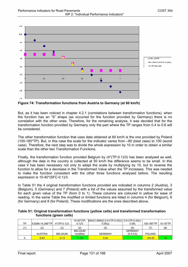
Performance indicators for Road Pavements COST 354 WP 2: "Individual Performance Indicators"
Final report Page 131 of 166 April 2007
Figure 74: Transformation functions from Austria to Germany (at 60 km/h) But, as it has been noticed in chapter 4.2.1 (correlations between transformation functions), when the function has an “S” shape (as occurred for the function provided by Germany) there is no correlation with the other ones. Therefore, for the remaining analysis, it was decided that for the transformation function provided by Germany only the part where the TP ranges from 0.4 to 0.6 will be considered. The other transformation function that uses data obtained at 60 km/h is the one provided by Poland (100-180*TP). But, in this case the scale for the indicator varies from –80 (best case) to 100 (worst case). Therefore, the next step was to divide the whole expression by 10 in order to obtain a similar scale than the other two Transformation Functions. Finally, the transformation function provided Belgium by (4*(TP-0.1)/3) has been analysed as well, although the data in the country is collected at 50 km/h the difference seems to be small. In this case it has been necessary not only to adapt the scale by multiplying by 10, but to reverse the function to allow for a decrease in the Transformed Value when the TP increases. This was needed to make the function consistent with the other three functions analysed before. The resulting expression is 10-40*(SFC-0.1)/3. In Table 51 the 4 original transformation functions provided are indicated in columns 2 (Austria), 3 (Belgium), 5 (Germany) and 7 (Poland) with a list of the values assumed by the transformed value for each given value of the TP (form 0 to 1). These columns are coloured in yellow for ease of reading. In the same Table the modified or limited functions are listed in columns 4 (for Belgium), 6 (for Germany) and 8 (for Poland). These modifications are the ones described above.
Table 51: Original transformation functions (yellow cells) and transformed transformation functions (green cells)
TP 9.9286-14.286*TP 4*(TP-0.1)/3 10-40*(TP-
0.1)/3 MAX(1;MIN(5;3.5+(TP-0.45)/(-
0.06))) 3.5+(TP-0.45)/(-
0.06) 100-180*TP 10-18*TP (1) (2) (3) (4) (5) (6) (7) (8)
AUSTRIA BELGIUM BELGIUM modified GERMANY
GERMANY (0.4-0.6) POLAND
0 9.93 -0.13 11.33 5.00 100.00 10

Performance indicators for Road Pavements COST 354 WP 2: "Individual Performance Indicators"
Final report Page 132 of 166 April 2007
TP 9.9286-14.286*TP 4*(TP-0.1)/3 10-40*(TP-
0.1)/3 MAX(1;MIN(5;3.5+(TP-0.45)/(-
0.06))) 3.5+(TP-0.45)/(-
0.06) 100-180*TP 10-18*TP (1) (2) (3) (4) (5) (6) (7) (8)
AUSTRIA BELGIUM BELGIUM modified GERMANY
GERMANY (0.4-0.6) POLAND
0.1 8.50 0.00 10.00 5.00 82.00 8.2 0.2 7.07 0.13 8.67 5.00 64.00 6.4 0.3 5.64 0.27 7.33 5.00 46.00 4.6 0.4 4.21 0.40 6.00 4.33 4.33 28.00 2.8 0.5 2.79 0.53 4.67 2.67 2.67 10.00 1 0.6 1.36 0.67 3.33 1.00 1.00 -8.00 -0.8 0.7 -0.07 0.80 2.00 1.00 -26.00 -2.6 0.8 -1.50 0.93 0.67 1.00 -44.00 -4.4 0.9 -2.93 1.07 -0.67 1.00 -62.00 -6.2 1 -4.36 1.20 -2.00 1.00 -80.00 -8
SCALE 0-1
SCALE 9.93-(-4.36)
SCALE (-0.13)-1.20
SCALE 11.33-(-2)
SCALE 5-1
SCALE 11-(-5.67)
SCALE 100-(-80)
SCALE 10-(-8)
60 KM/H 50 KM/H 50 KM/H 60 KM/H 60 KM/H 60 KM/H 60 KM/H When combining the different transformation functions the following results are obtained: - The linear regression obtained by combining the two functions is listed in columns 4 and 5 of
Table 51 (9.9286-14.286*TP and 3.5+(TP-0.45)/(-0.06)) a linear correlation between the Transformed Value and the TP can still be derived with a very high determination coefficient of 0.999, as shown in Figure 75;
- Combining the three functions listed in columns 4, 5 and 8 of Table 51 (all related to a 60 km/h measurement), the diagram shown in Figure 76 is obtained. There is more scatter than before but a linear correlation can still be obtained with a determination coefficient is still very high (0.955);
- The linear regression obtained using all the 4 transfer functions available (columns 3, 4, 5 and 8 of Table 51) is characterised by a lower determination coefficient (0.8979) as shown in Figure 77.
Figure 75: Correlation between the transformation functions: 9.9286-14.286*TP and 3.5+(TP-
0.45)/(-0.06)

Performance indicators for Road Pavements COST 354 WP 2: "Individual Performance Indicators"
Final report Page 133 of 166 April 2007
Figure 76: Correlation between the transformation functions: 9.9286-14.286*TP. 3.5+(TP-
0.45)/(-0.06) and 10-18*TP
Figure 77: Correlation between the transformation functions: 9.9286-14.286*TP. 3.5+(TP-
0.45)/(-0.06). 10-18*TP and 10-40*(SFC-0.1)/3
As it can be seen the accuracy of the transformation function decreases as the number of functions averaged is increased but there is still a very good determination coefficient when all 4 of the available functions (modified as described earlier) are considered. For this reason it was decided to consider this function as the proposed transfer function. Given the fact that the Transformed Value ranges from 10.41 (when TP is 0) to -4.8 (when TP is 1) while the unitless Performance Index for friction (PI_F) has to range from 5 (very poor) to 0 (very good) the transfer function had been modified accordingly. It should be noted that the minimum and maximum value of the Transformed Values do not necessarily match the minimum and maximum values of the PI_F.

Performance indicators for Road Pavements COST 354 WP 2: "Individual Performance Indicators"
Final report Page 134 of 166 April 2007
To relate these two indices the same assumptions already discussed in section 1 were made (see chapter 1.5.2) these were: - The threshold level is assumed to represent the limit between poor and very poor conditions
(PI_F=4); - The warning level is assumed to represent the limit between fair and poor conditions (PI_F=3). For this analysis the limits derived for primary roads for SFC and LFC devices have been considered. The details on these limits are described in chapters 4.2.2.1.1 and 4.2.2.1.2 of this report. In Table 52 the values of PI_F obtained through these assumptions and the Transformed Values (Y) obtained by means of the transformation function defined earlier are shown. As it can be seen they can differ considerably (form 4 to 5.24 in the case of the LFC transfer function). It was therefore decided to average the two figures to obtain an overall transfer function, limited between PI_F=0 and PI_F=5 as shown in Figure 78. The proposed transfer functions are therefore:
• When measuring with SFC devices (or other side force coefficient devices) at an operating speed of 60 km/h:
PI_F = MAX(0;MIN(5;-17.600*SFC+11.205)) being SFC in a 0 to 1 scale. • When measuring with LFC devices at an operating speed of 50 km/h:
PI_F = MAX(0;MIN(5;-13.875*LFC+9.338)) being LFC in a 0 to 1 scale.
Table 52: Indices obtained by using the three transformation functions
LIMIT VALUES
in a [0 to 1] scale PI_F Y=-15.215X+10.412 THRESHOLD SFC (at 60 km/h) 0.40 4 4.33 WARNING SFC (at 60 km/h) 0.45 3 3.57 THRESHOLD LFC (at 50 km/h) 0.34 4 5.24 WARNING LFC (at 50 km/h) 0.42 3 4.02
0
1
2
3
4
5
6
0 0.2 0.4 0.6 0.8 1
PI_F
Friction TP
Transformed Value
SFC Limits
LFC Limits
PI_F Vs. SFC TP
PI_F Vs. LFC TP
Figure 78: comparison between thresholds and warning limits and Transformed Values and
proposed PI_F functions.

Performance indicators for Road Pavements COST 354 WP 2: "Individual Performance Indicators"
Final report Page 135 of 166 April 2007
4.7 CORRELATION BETWEEN THE SELECTED INDICATOR AND THE USED INDICATORS
The results included in this chapter are those obtained by correlating the indicators used by the four countries that provided transformation functions versus the indicators calculated from the proposed transformation functions. The device used by each of these four countries has been taken into account in order to select the adequate proposed transformation function. The regression obtained by taking into account the indicators used in Austria is included in Figure 79. Austria reports in the database 5 classification classes (very good, good, fair, poor and very poor) with the indicators varying from 1 to 5. Such scale is the one that has been taken into account to obtain the results in Figure 79.
Figure 79: Proposed indicator vs. Austrian indicator Again, 5 classes have been reported for the indicator used in Belgium, with a scale from 1 (very good) to 0 (very poor). The results of the correlation are shown in Figure 80. Although these results seem to be good, statistically it is not acceptable to create a correlation like the one shown by using the whole range. That is the reason why in the same figure the linear regression in the range 0.8 to 0.2 has been obtained as well (pink colour). In this case the correlation is acceptable and the difference between it and the other regression in the same figure is that the cases classified as very poor and very good are not included.
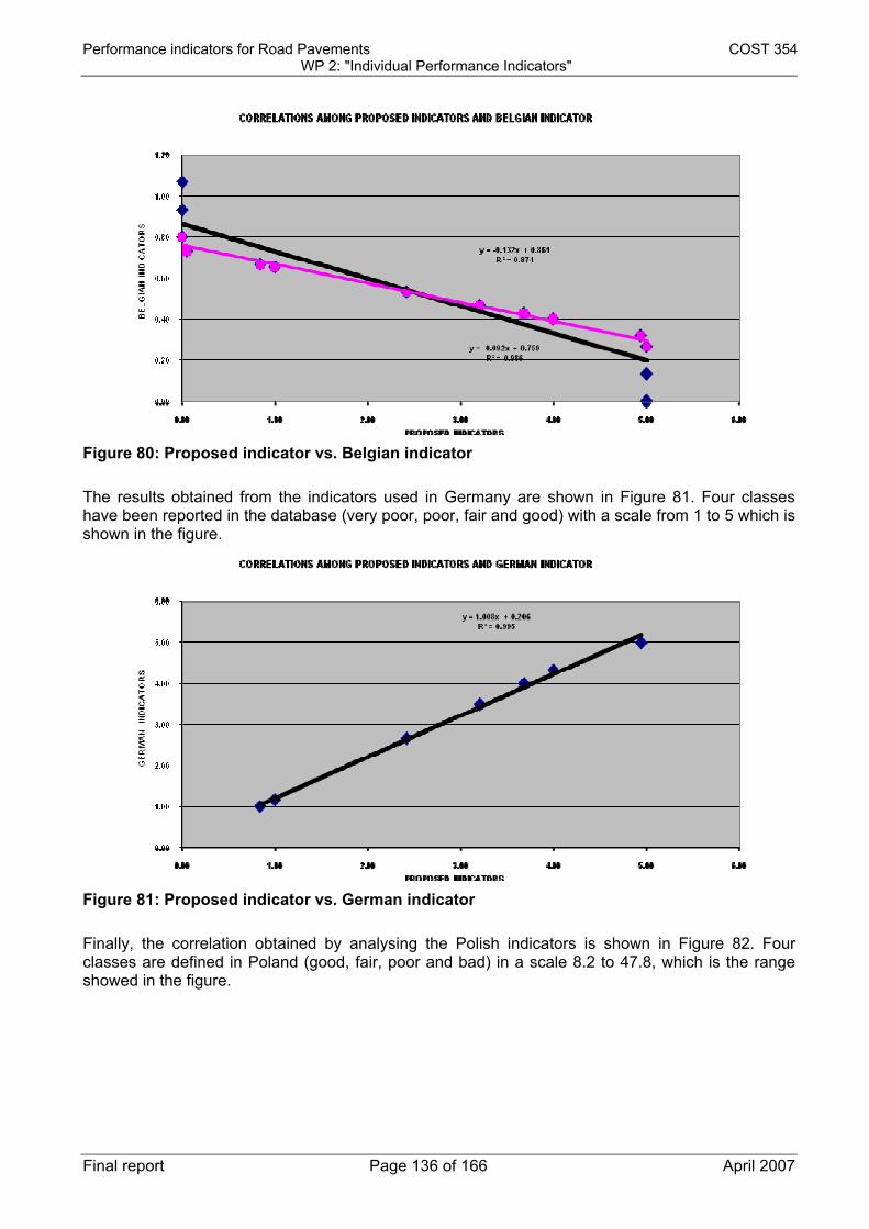
Performance indicators for Road Pavements COST 354 WP 2: "Individual Performance Indicators"
Final report Page 136 of 166 April 2007
Figure 80: Proposed indicator vs. Belgian indicator The results obtained from the indicators used in Germany are shown in Figure 81. Four classes have been reported in the database (very poor, poor, fair and good) with a scale from 1 to 5 which is shown in the figure.
Figure 81: Proposed indicator vs. German indicator Finally, the correlation obtained by analysing the Polish indicators is shown in Figure 82. Four classes are defined in Poland (good, fair, poor and bad) in a scale 8.2 to 47.8, which is the range showed in the figure.

Performance indicators for Road Pavements COST 354 WP 2: "Individual Performance Indicators"
Final report Page 137 of 166 April 2007
Figure 82: Proposed indicator vs. Polish indicator From the results obtained in this chapter, it can be concluded that the correlations between the national indicators analysed here and the proposed indicators seems to be acceptable in the range used in each country.
4.8 REFERENCES
1. PIARC “International PIARC Experiment to Compare and Harmonize Texture and Skid
Resistance Measurements” Doc. AIPCR 01.04.T-1995 2. HERMES – “Harmonization of European Routine and research Measuring Equipment for
Skid Resistance”, FEHRL Project (www.fehrl.org)

Performance indicators for Road Pavements COST 354 WP 2: "Individual Performance Indicators"
Final report Page 138 of 166 April 2007
SECTION 5: NOISE
5.1 NOISE POLLUTION INDICATORS FROM THE COST 354 DATABASE
Only 4 of the involved 22 countries represented in the database have provided information about noise pollution. Analyzing the database it was found that several answers from one country mean that, as a matter of fact, different measuring devices or different technical parameters are used and therefore it is correct that they are included in further analyses. Table 53 shows that 7 records are analyzed.
Table 53: Number of countries, questionnaires and records referred to noise performance indicator
TOTAL Noise COUNTRY
Nº QUESTIONNAIRES Nº RECORDS
AUSTRIA (AT) 1 2
NETHERLANDS (NL) 1 3
SPAIN(ES) 1 1
UNITED KINGDOM (UK) 1 1
4 7
5.1.1 General information For the noise pollution performance indicator different technical parameters are used in individual countries. TP are in the database described with: the name, the TP description, the abbreviation, the unit the measuring equipment and measuring principle. WG 1 unified the information because some fields contained different information for the same equipment or measuring principle. In the database there are 4 unified types of technical parameters describing noise pollution: CPX: A-weighted sound pressure level measured by microphones located close to the tyre-
road interface. SPB: Maximum A-weighted sound pressure level measured by road side microphones N: Laser Lden: Noise predictive model calculation and/or sound level meter measurements

Performance indicators for Road Pavements COST 354 WP 2: "Individual Performance Indicators"
Final report Page 139 of 166 April 2007
Table 54 gives an overview of the relevant information. The column Name Ind (unified) is partly empty in the COST-354 database and completed in Table 54. The identified TPs are then summarized in Table 55.
Table 54: Description of noise technical parameters from the COST-354 Database Code-
Country Name Name TP
(unified) TP description Measuring Principle (unified) Name Ind
(unified) AT Rolling
noise Tyre/road sound level
Rolling noise level
A-weighted sound pressure level measured by microphones located close to the tyre-road interface
CPX
AT Pass-by noise
Tyre/road maximum sound pressure level
Statistical pass-by index
Maximum A-weighted sound pressure level measured by road side microphones
SPB
ES Rolling noise
Tyre/road sound level
Rolling Noise A-weighted sound pressure level measured by microphones located close to the tyre-road interface
CPX
UK Noise Noise Noise Laser N
NL Noise characteristic
Tyre/road maximum sound pressure level
effect road surface on noise emission
Maximum A-weighted sound pressure level measured by road side microphones
SPB
NL Noise characteristic
Tyre/road sound level
noise emission A-weighted sound pressure level measured by microphones located close to the tyre-road interface
CPX
NL Environmental noise
A-weighted long term average sound level
Long term average soundlevel
Noise predictive model calculation and/or sound level meter measurements
Lden
Table 55: Summary of technical parameters specified for noise
Name of the index No. records No. Countries Countries SPB 2 2 A, NL CPX 3 3 A, E, NL Lden 1 1 NL N 1 1 GB
5.1.2 Category of the PI All indicators are (only) related to Environment.

Performance indicators for Road Pavements COST 354 WP 2: "Individual Performance Indicators"
Final report Page 140 of 166 April 2007
Road safety Pavement structure
Riding Comfort
0
7
00
0 0
0
Environment
0
0
0 0
0 0
Figure 83: Distribution of noise PI by category
5.1.3 Field of application – distribution by road network All indicators are applicable on Motorways and Primary Roads, the main issues for this COST-action.
Motorways Primary Roads
Secondary Roads
0
0
00
0 0
0
Other
4
0
03
0 0
Figure 84: Distribution of noise PI by road network
5.1.4 Distribution by Level of Application Based on the data contained in the COST 354 database the following conclusions on the use of noise PIs can be drawn:
• CPX can only be used on project level (1 country didn’t answer the question). • SPB can either be used on only network (NL) or only project (AT) level. • Lden and Noise can be used on both network and project level.

Performance indicators for Road Pavements COST 354 WP 2: "Individual Performance Indicators"
Final report Page 141 of 166 April 2007
Not specified: 1
Network - Level Project - Level
2 1 3
Figure 85: Distribution of noise PI by level of application
5.1.5 Distribution by Pavement Type All methods can be used on the 3 pavement types.
Flexible Pavement
Rigid Pavement
0 0 0
Semi-rigid pavement
0 70
0
Figure 86: Distribution by pavement type
5.1.6 Type of application Only Lden refers to both standard and research (name of the standard is Directive 2002/49/EC d.d. 25 June 2002).

Performance indicators for Road Pavements COST 354 WP 2: "Individual Performance Indicators"
Final report Page 142 of 166 April 2007
Not specified: 2
Standard Research
1 0 4
Figure 87: Distribution by type of application
5.1.7 Standardization Table 56 shows the standards in use for noise measurement. As it can be seen SPB is the only TP that refers to an international standard; an international standard for CPX is under development.
Table 56: Standards and specifications used for noise performance indicators
Code-Country
Name Ind
(unified)
Standard Name of Standard Equipment Name
AT CPX National Standard
RVS 11.066 - Teil IV, Rollgeraeuschmessung
Rolling noise trailer
AT SPB ISO-Standard ISO 11819-1 Acoustics - Measurement of the influence of road surfaces on traffic noise, part I: Statistical pass-by method
Microphone
ES CPX ISO-Standard ISO/CD 11819-2 Acoustics - Method for measuring the influence of road surfaces on traffic noise. Part 2: The close-proximity method
UK N Technical Specification
IAN 42/05 - Traffic-Speed Condition Surveys (TRACS): Revised Assessment Criteria
Road Assessment Vehicle (RAV)
NL SPB ISO-Standard ISO 11819-1 Acoustics - Measurement of the influence of road surfaces on traffic noise, part I: Statistical pass-by method
NL CPX Technical Specification
ISO/CD 11819-2 Acoustics - Method for measuring the influence of road surfaces on traffic noise. Part 2: The close-proximity method
CPX trailer
NL Lden EC-Standard Directive 2002/49/EC d.d 25 June 2002
VenW wegen geluid model/Silence
5.1.8 Measuring principle The details of the different measuring principles used for noise PIs are shown in Table 57.

Performance indicators for Road Pavements COST 354 WP 2: "Individual Performance Indicators"
Final report Page 143 of 166 April 2007
Table 57: measuring principle details
Code-Country
Name Ind (unified)
Details of Data Collection (as given in the database)
AT CPX 2 microphones in defined distances to the tyre (PIARC tyre) AT SPB maximum A-weighted sound pressure level (SPL),vehicle speed ES CPX Number of measurements depend on speed. Averaged each 20 m. Data
are processed to obtain homogeneous section with hypotheses of normal distribution and 95% confidence. Measurements are corrected depending on actual speed and pavement temperature
UK N Noise calculated using algorithm based on surface type and texture profile. NL SPB SPL measurement alongside the road on regular vehicles passing by,
combined with speed measurement. Regression analysis gives a normalised SPL at specified speeds for 3 vehicle categories, passenger cars / dual axle and multi axle heavy vehicles.
NL CPX SPL measurement with 2 microphones at short distance from car tires. SPL data is measured over 20m segments. Result is the average over 4 different specified tires.
NL Lden Using parameters for the road (location, elevation, traffic, volume & speed) sound levels from the traffic on the road are generated. Based on this and the characteristics of the surroundings the sound level on a certain distance can be calculated.
5.2 COMPLEMENTARY INFORMATION DERIVED FROM LITERATURE
5.2.1 HARMONOISE The HARMONOISE project (Aug 2001- Jan 2006) produced methods for the prediction of environmental noise levels by road and railway traffic (3). These methods are intended to become the harmonized methods for noise mapping in all EU Member States. The methods are developed to predict the noise levels in terms of Lden and Lnight , which are the harmonized noise indicators according to the Environmental Noise Directive 2002/49/EC. Reports can be found on: http://www.imagine-project.org
5.2.2 Silvia The EU Fifth Framework Project “SILVIA – Sustainable Road Surfaces for Traffic Noise Control” provided a “Guidance manual for the implementation of low-noise road surfaces” (4), published as a FEHRL Report. The manual gives the following measurement procedure1: “9.3 Labelling procedures in the classification system The classification system identifies specific measurement procedures necessary for labelling the acoustic performance of a road surface. These measurement procedures are described in Appendix A. There are two possible labelling procedures:
• LABEL1 (preferred): Assessment based on SPB and CPX measurements; • LABEL2: Assessment based on SPB measurements and measurements of intrinsic
properties of the road surface, e.g. texture and sound absorption. 1 The literature references in square brackets are referred to the Silvia report reference list. With reference to the current report the following correspondence can be established: [26] is ref (1) of this report while [113] is reference (2). More details on SILVIA references can be found in (4).

Performance indicators for Road Pavements COST 354 WP 2: "Individual Performance Indicators"
Final report Page 144 of 166 April 2007
Both noise labels are based on SPB measurements [26]. However, due to the limitations of the SPB method in assessing only a small section of a test surface, additional measurements to assess the acoustic performance over the full length of the trial section is required. LABEL1 includes a direct assessment of noise over the entire length of the trial surface using the CPX method [113] and is the preferred method. LABEL2 allows for an indirect assessment based on measurements of the intrinsic properties of the surface which can be related to the generation and propagation of noise e.g. texture and sound absorption.” CPX is used by at least: - U.K., Norway, Sweden/Poland, Germany, Spain, USA, Netherlands, France, Austria, Denmark,
Finland
5.2.3 Environmental Noise Directive 2002/49/EC The Environmental Noise Directive is a direct result of the European Union's Noise Policy Green Paper from 1996. It covers transportation and industrial noise in the environment. The directive requires that noise maps and action plans (noise policy) be made for:
• Agglomerations with populations greater than 100 000 • Major roads with more than 3 000 000 vehicles a year (approximately 8 000 a day) • Major railways with more than 30 000 trains a year • Major civil airports with more than 50 000 operations per year (approximately 135 day)
Noise maps show the LDEN (the LAeq where evening and night time levels are given a penalty of 5 and 10 dB, respectively) and Lnight (the night time LAeq) of each type of source (road, rail, industry, etc.) at a height of 4m over the ground. Aggregation of levels from different sources can be performed with a stated method. The European Union requires the making of maps of transportation and industrial noise using current models that comply with certain demands. The following methods are recommended:
• Industrial sites: ISO 9613 • Roads: NMPB-96 (the French method) • Railways: RLM2 (the Dutch method) • Airports: ECAC 29
Later, noise maps are made using harmonized techniques. The general public must be informed and consulted during the process, and the European Environment Agency in Copenhagen will collate the result in a central European database. The first maps for major areas are required by mid 2007, and action plans required one year later. These activities are repeated at five yearly intervals and all defined areas are incorporated in the following round of deadlines starting in 2012. The above are minimum requirements and some countries are expected to go further and faster. The text of the directive in English can be found on http://europa.eu.int/.
5.3 SELECTION OF THE PROPOSED INDIVIDUAL PERFORMANCE INDICATOR The criteria for selection of the “best” individual performance indicators are described in 1.3. These criteria have been applied to the noise performance indicators and the results are shown in Table 58. It should be noted that:
• SPB is a static measurement and therefore not suitable for network-measurement • Lden: the EC is working on a harmonized method for predicting noise levels. HARMONOISE
will hopefully be operational in 5 years (see paragraph 5.2). This is more or less a static measurement (computer model).

Performance indicators for Road Pavements COST 354 WP 2: "Individual Performance Indicators"
Final report Page 145 of 166 April 2007
Table 58: selection table for technical parameters
SPB CPX Lden Noise
European/Int. standard
ISO 11819-1 AT refers to a national standard. NL to ISO TC43.ES to ISO/CD 11819-2. It will take some years before we have ISO 11819-2.
EC-standard: Directive 2002/49/EC dd 25 June 2002
No
Standard practice or research
Standard practice
Research (EU-programme Silenda Via / SILVIA)
Both Research
Wide use Only 2 answers but widely spread.
Participation of around12 EU-countries
? Probably not (only in GB?)
Device independent
Yes Probably yes Yes No (RAV/laser)
Safe to collect Yes Probably yes Yes Yes Reliable Yes Probably yes Yes Unknown Sustainable Yes Probably yes Yes Unknown
We do not have the elements to provide a PI for noise pollution at the moment: - SPB is the only standardized method but it cannot be used for monitoring (it has very strict
constraints for the selection of the measurement site and is not suitable for network-measurement);
- CPX is the only real solution but the ISO EN standard is still under development. The proposal could be: within a couple of years the method to be used is CPX, the index is the one defined by the EN ISO standard and the procedure will be that. It is worth noting that a PI for noise is not for the interest of road users and road operators, but for the environment of the road. Therefore we need computer models that combine characteristics of the pavement (like SBP or CPX), traffic (amount and speed), surrounding etc.
5.4 REFERENCES
1. ISO 11819-1 “Acoustics - Measurement of the influence of road surfaces on traffic noise, part I: Statistical pass-by method”
2. ISO/CD 11819-2 “Acoustics - Method for measuring the influence of road surfaces on traffic noise. Part 2: The close-proximity method”
3. HARMONOISE “Harmonised Accurate and Reliable Methods for the EU Directive on the Assessment and Management Of Environmental Noise” Final Reports (http://www.imagine-project.org)
4. SILVIA “Guidance Manual For The Implementation of Low-Noise Road Surfaces”, FEHRL Report 2006/02

Performance indicators for Road Pavements COST 354 WP 2: "Individual Performance Indicators"
Final report Page 146 of 166 April 2007
SECTION 6: AIR POLLUTION
6.1 AIR POLLUTION INDICATORS FROM THE COST 354 DATABASE
According to the information in the database only 1 of the 24 countries involved gave information about air pollution. The 2 records deal with different technical parameters.
Table 59: Number of countries, questionnaires and records referred to air pollution performance indicator
TOTAL Noise COUNTRY Nº QUESTIONNAIRES Nº RECORDS
NETHERLANDS (NL) 1 2
1 2
Afterwards Sweden added some information; this information is used as far as possible in this overview.
6.1.1 General information For the air pollution performance indicator different technical parameters are used. TP are in the database described with: the name, the TP description, the abbreviation, the unit the measuring equipment and measuring principle. WG 1 unified some information. In the database there is 1 unified type of technical parameters describing air pollution: Pollution density. Table 60 gives an overview of the relevant information which are then synthesised in Table 61. The column Name Ind (unified) is empty in the database and completed in Table 60.
Table 60: Description of air pollution technical parameters for COST-354 database
Code-Country Name
Name TP (unified) TP description
Measuring Principle (unified)
Unit TP
Name Ind (unified)
NL NO2 concentration
Pollution density
NO2 concentration
Prefiltering and reactive impregnation
µg/ m3 NO2
NL PM10 concentration
Pollution density
PM10 concentration
Total amount of filterable particulate
µg/ m3 PM10
SE Pollution density
PM10 concentration
µg/m3 PM10

Performance indicators for Road Pavements COST 354 WP 2: "Individual Performance Indicators"
Final report Page 147 of 166 April 2007
Code-Country Name
Name TP (unified) TP description
Measuring Principle (unified)
Unit TP
Name Ind (unified)
SE Road surface PM10 load
Pollution density
PM10 mass per m2 road surface
mg/ m2
Table 61. Summary of technical parameters specified for air pollution Name of the index No. records No. Countries Countries
PM10 2 2 NL, SE NO2 1 1 NL
Road surface PM10 load 1 1 SE
6.1.2 Category of performance indicator In this sub-section and in the following paragraphs of this chapter only the data coming from the COST-354 database are used. Both indicators are related only to environmental issues.
Road safety Pavement structure
Riding Comfort
0
2
00
0 0
0
Environment
0
0
00
0 0
Figure 88: Distribution of air pollution PI by category
6.1.3 Field of application – distribution by road network Both indicators are applied only on Motorways and Primary Roads.
Motorways Primary Roads
Secondary Roads
0
0
00
0 0
0
Other
2
0
00
0 0

Performance indicators for Road Pavements COST 354 WP 2: "Individual Performance Indicators"
Final report Page 148 of 166 April 2007
Figure 89: Distribution of air pollution PI by road network
6.1.4 Distribution by Level of Application Both indicators are applied only at network level.
Network - Level Project - Level
0 2 0
Figure 90: Distribution of air pollution PI by Level of Application
6.1.5 Distribution by Pavement type Both indicators are applicable for flexible and rigid pavements.
Flexible pavements
Rigid pavements
2 0 0
Semi-rigid pavements
0
0
0
0
Figure 91: Distribution of air pollution PI by pavement type
6.1.6 Type of application Both indicators are considered standard practices.

Performance indicators for Road Pavements COST 354 WP 2: "Individual Performance Indicators"
Final report Page 149 of 166 April 2007
Standard Research
0
2 0
Figure 92: Distribution of air pollution PI by type of application
6.1.7 Standardization Table 62 shows that there is no international standard to measure air pollution. This table also includes data from Sweden not included in the COST-354 database. Sweden mentioned TEOM as a European standard, but there is not enough information.
Table 62: Standards and specifications used for air pollution performance indicators Code-Country Name Ind (unified) Standard Name of Standard
NL NO2 No Standard VLW air quality model NL PM10 No Standard VLW air quality model SE PM10 ? TEOM SE ? TEOM
6.1.8 Measuring principle Table 63 details the measuring principles adopted by the Netherlands (as described in the COST-354 database) and Sweden (not in the database) for air pollution characterization.
Table 63: Measuring principle details
Code-Country
Name Ind (unified)
Measuring principle (unified)
Description of measuring principle
NL NO2 Total amount of filterable particulate
Model calculation. Transfers profile till 1 km from middle of road, measurement on 10, 20, 30, 40, 50, 75, 100, 200, 300, 400, 500, 750, 1000 m from middle of road, input, traffic intensities, % heavy trucks, meteorology, characteristics of road, roughness surrounding
NL PM10 Prefiltering and reactive impregnation
Model calculation. Transfers profile till 1 km from middle of road, measurement on 10, 20, 30, 40, 50, 75, 100, 200, 300, 400, 500, 750, 1000 m from middle of road, input, traffic intensities, % heavy trucks, meteorology, characteristics of road, roughness surrounding
SE PM10 TEOM Gravimetric method with detection of mass induced frequency changes of oscillating glass rod.
SE N WDS (Wet Dust Sampler)
High-pressure water cleans the surface and the cleaning water is sampled and analyzed for particle sizes.

Performance indicators for Road Pavements COST 354 WP 2: "Individual Performance Indicators"
Final report Page 150 of 166 April 2007
6.2 EVALUATION OF THE MOST SUITABLE PERFORMANCE INDICATORS
6.2.1 Name of the indices and transformation function Name of the indices:
PM10 concentration NO2 concentration
There are no transformation functions.
6.2.2 Limits There is legislation from EU: Council Directive 1999/30/EC (limit values for sulphur dioxide, nitrogen dioxide and oxides of nitrogen, particulate matter and lead in ambient air). PM10 concentration
Averaging Period Limit Value (threshold) Date by which limit value is to be met
1. 24-hour limit value
24 hours 50 µg/m3 PM10 not to be exceed more than 35 times a calendar year
1st January 2005
2. Annual limit value
Calendar year 40 µg/m3 PM10 1st January 2005
NO2 concentration
Averaging Period Limit Value (threshold) Date by which limit value is to be met
1. Daily limit value Calendar year 40 µg/m3 NO2 1st January 2010
6.3 SELECTION OF THE PROPOSED INDIVIDUAL PERFORMANCE INDICATOR The criteria for selection of the “best” individual performance indicators are described in 1.3. The results for these criteria when applied to air pollution are shown in Table 64.
Table 64: Selection table for technical parameters
PM10 concentration
PM10 concentration (TEOM)
NO2 concentration Road surface PM10 load
1 European/Int. standard
No Yes ? No No
2 Standard practice or research
Standard Standard Standard Research
3 Wide use ? Yes ? No 4 Device Yes Yes Yes ?

Performance indicators for Road Pavements COST 354 WP 2: "Individual Performance Indicators"
Final report Page 151 of 166 April 2007
independent 5 Safe to collect Yes Yes Yes Yes 6 Reliable Yes Yes Yes ? 7 Sustainable Yes Yes Yes Yes
Proposal for the selection of the best PI
a. There is no international standard to measure air pollution. There is however legislation from the EU.
b. There are Council Directives (e.g. 96/62/EC http//europa.eu.int/ and 1999/30/EC http//europa.eu.int/) that form a framework in the way EU-countries inform Brussels about air-pollution. The EU-countries are obliged to do static measurements. The use of additional information from computer models is allowed and there are some rough restrictions on quality, reliability etc.
Because there is legislation from the EU, the following PI’s are recommended: PM10 concentration NO2 concentration
6.4 PROTOCOLS AND TEST METHODS FOR MEASURING THE PROPOSED INDIVIDUAL INDICATORS.
There are no strict protocols; the following should be used: a. NO2: Annex IX of Council Directive 1999/30/EC refers to ISO 7996: Ambient air -- Determination
of the mass concentration of nitrogen oxides -- Chemiluminescence method. b. PM10 : Annex IX of Council Directive 1999/30/EC refers to pr EN 12341: Air Quality – Field Test
Procedure to Demonstrate Reference Equivalence of Sampling Methods for the PM10 fraction of particulate matter.
6.5 ASSESSMENT OF THE TRANSFORMATION FUNCTIONS There is no data to define a 0 to 5 scale. According to the existing data only 2 classes for both NO2 and PM10 can be defined: Limits January 1st 2005 Class NO2 PM10 1 < 60 - x µg/m3 < 40 µg/m3 2 >=60 - x µg/m3 >=40 µg/m3
x= 20/9 for each year between 2001 and 2010 Limits January 1st 2010 Class NO2 PM10 1 < 40 µg/m3 < 20 µg/m3 2 >= 40 µg/m3 >= 20 µg/m3

Performance indicators for Road Pavements COST 354 WP 2: "Individual Performance Indicators"
Final report Page 152 of 166 April 2007
SECTION 7: BEARING CAPACITY
7.1 BEARING CAPACITY INDICATORS FROM THE COST 354 DATABASE
Out of the 22 countries represented in the COST354 Database used for the analysis, 12 submitted responses about bearing capacity (55%). The majority of them reported one questionnaire per country. However, UK, Greece, Denmark and Spain submitted two questionnaires each, leading to a total of 16. The list of countries that submitted questionnaires, together with number of records is presented in Table 65.
Table 65: Numbers of countries, questionnaires and records referred to the bearing capacity performance indicator
Total Country Nº Questionnaires
Austria 1 Denmark 2 France 1 Greece 2 Hungary 1 Italy 1 Portugal 1 Serbia and Montenegro 1 Slovenia 1 Spain 2 Switzerland 1 United kingdom 2 TOTAL 16
7.1.1 General information In the COST 354 database there are 5 different technical parameters (TP) identified as bearing capacity performance indicators:
− Deflection; − Structural number; − Residual life; − E-modulus; − Deflection velocity.
The majority of the countries use deflection as a technical parameter for bearing capacity (12 out of 16 responses representing 10 out of 12 countries). Slovenia only uses residual life while Hungary only uses E-modulus as the TP for bearing capacity. Greece uses structural number as a TP in addition to Deflection and Denmark uses deflection velocity in addition to Deflection. Figure 93 and Table 66 provide a summary of the analysed technical parameters and corresponding countries where they are used.

Performance indicators for Road Pavements COST 354 WP 2: "Individual Performance Indicators"
Final report Page 153 of 166 April 2007
TP for bearing capacity PI
76%
6%
6%6% 6%
Deflection Structural number Residual life E-modulus Deflection velocity
Figure 93: Technical parameters for bearing capacity performance indicator
Table 66: Summary of technical parameters specified for bearing capacity
Technical Parameter No. Records
No. Countries Countries
Deflection 12 10 UK[2], AT, EL, IT, FR, CH, DK, PT, ES[2], CS, HR(*)
Structural number 1 1** EL Residual life 1 1 SI E-modulus 1 1 HU Deflection velocity 1 1** DK * information not in the COST database used for the analysis, obtained during the WG2 work. It is not included in the following distribution analyses. ** these countries use also deflection as a TP for bearing capacity
7.1.2 Category of performance indicator In terms of distribution by PI categories the bearing capacity indices are, as expected, always used as pavement structural indicators. As shown in Figure 94 no responders indicated that bearing capacity indices are used also for safety or riding comfort indicators.

Performance indicators for Road Pavements COST 354 WP 2: "Individual Performance Indicators"
Final report Page 154 of 166 April 2007
Riding Comfort 0
0
0
0
16 0
0
Road Safety
Pavement Structure
Figure 94: distribution of bearing capacity PI by category
7.1.3 Field of application – distribution by road network According to the database responses, bearing capacity indices are essentially used in motorways and primary roads with few countries indicating that this type of indicator is also used in secondary roads, as shown in Figure 95. Specifically Slovenia indicated that bearing capacity indices are used only for primary and secondary roads, Hungary, Denmark - only for deflection - and Serbia-Montenegro indicated that these performance indicators are used for motorways, primary roads and secondary roads and only Italy and Switzerland have indicated that these indicators refer to all types of roads. In a general sense it can be stated that, in the majority of the countries represented in the bearing capacity section of the COST 354 database, the bearing capacity indicators are essentially used for highly trafficked roads.
Motorways Primary Roads
Other Roads
2
0
02
0 0
0
Secondary Roads
8
1
3 0
0 0
Figure 95: distribution of bearing capacity PI by road network

Performance indicators for Road Pavements COST 354 WP 2: "Individual Performance Indicators"
Final report Page 155 of 166 April 2007
7.1.4 Distribution by Level of Application It was extremely interesting to observe that 5 out of the 16 (31%) responses (Denmark – only for the deflection velocity, Italy, Portugal, Slovenia and Switzerland) indicated that the bearing capacity PI is used only at a network level while 4 (25%) responses indicated that the bearing capacity indicators are used both at network and project level. Only 7 responses indicated the bearing capacity index as a project level indicator only.
Not specified : 0
Network - Level Project - Level
45 7
Figure 96: Distribution of bearing capacity PI by level of application
7.1.5 Distribution by Pavement Type In terms of application of the different indicators to different pavement types most of the responders (9 out of 16) indicated that these are used for both flexible and semi-rigid pavements, while 4 indicated that these are used for all pavement types (Figure 97). It could seem strange that 3 responders (Serbia-Montenegro, Slovenia and Switzerland) indicated that the bearing capacity PI is used for flexible pavements but not for semi-rigid ones. It should be noted however that these countries did not provide any response at all which referred to semi-rigid pavements throughout the database. This indicates that is likely these countries do not use semi-rigid pavements. In the same manner it should be noted that rigid pavements are only used by a minority of countries among the responders to the questionnaire.

Performance indicators for Road Pavements COST 354 WP 2: "Individual Performance Indicators"
Final report Page 156 of 166 April 2007
Not specified : 0
Flexible pavements
Rigid pavements
1 2 0
Semi-rigid pavements
9 4
0
0
Figure 97: Distribution of bearing capacity PI by pavement type
7.1.6 Distribution by Type of Application In terms of distribution by type of application (standard or research) it is quite interesting to observe that 6 out of 16 (37.5%) did not specify to which type of application the PI could be referred (Figure 98). Most of the others indicated that is a standard practice (7 out of 16) or both a standard practice and a research activity (2 out of 16). Only the Deflection Velocity index used in Denmark is applied only at a research level.
Not specified : 6
Standard Research
27 1
Figure 98: Distribution of bearing capacity PI by type of application
7.1.7 Standardisation One of the questions in the COST 354 questionnaire was whether the technical parameter is measured according to a national or international standard or if a technical specification was used instead. From the results of the questionnaire synthesised in Table 67 it can be seen that no country refers to an international standard while most of them (excluding only Portugal, UK and Denmark for the deflection velocity) refer either to a national standard or to a technical specification.

Performance indicators for Road Pavements COST 354 WP 2: "Individual Performance Indicators"
Final report Page 157 of 166 April 2007
Table 67: Standards and specifications used for bearing capacity performance indicators
Country Standard [NS = national standard; IS = international standard; TS = technical specification]
Technical Parameter
Austria NS:
Evaluation according to RVS 11.066-Teil III, Deflektionsmessung Benkelmanbalken, optische Methode und Deflectorgraf Lacroix
Deflection
Croatia(*) NS:
HRN U.E4.016: Equipment and methods of deflection measurements HRN U.E4.018: Determination of relevant elastic deflection for flexible pavements
Deflection
Deflection velocity
Denmark NS: Konstruktion og vedligehold af veje og stier, Hæfte 4, Vedligehold af færdselsarealet,
Juni 2004. Deflection
France NS: Méthode LPC n° 39 Deflection
TS: FWD measurements and evaluation: Draft report of NTUA for the Greek Public Ministry Deflection
Greece Structural
number
Hungary TS:
ÚT 2-2.121/2000 Dinamikus behajlásmérés méretezéshez (KUAB) (Dynamic bearing capacity meassurement by KUAB apparatus)
E-Modulus
Italy TS: ASTM D 4694-96; ASTM D 4595-96; ASTM D 5858-96 Deflection
Portugal Deflection
Serbia and Montenegro
NS: JUS U.E8.016 (1981), JUS U.E8.018 (1981)
Deflection
Slovenia NS: TSC 06.630 Pavement surface properties, Deflections Residual life
NS: NLT 338/98 Medida de las deflexiones de firmes con deflectómetro de impacto. 6.3 I.C.
Instrucción para la rehabilitación de firmes Deflection Spain
Deflection
Switzerland NS: SN 670 362a "Poutre de Benkelman" Deflection
Deflection United Kingdom Deflection
* information not in the COST database used for the analysis, obtained during the WG2 work. It is not included in the following distribution analyses.
A grouping of the responses in terms of type of standards used for the different Technical Parameters is shown in Figure 99. It can be seen that most of the applications based on deflections are supported by either a technical specification or a standard, however 4 responses (Portugal, Spain [1 out of 2] and UK [2]) indicate that no standard or technical specification is available for that specific application. Out of the other 4 PIs 2 (residual life in Slovenia and E-modulus in Hungary) are based on either a national standard or a technical specification while Structural Number in Greece and Deflection Velocity in Denmark have no specification.

Performance indicators for Road Pavements COST 354 WP 2: "Individual Performance Indicators"
Final report Page 158 of 166 April 2007
7 6
1
3
2
1
6
4
1 10
2
4
6
8
10
12
14
16
18
Total Deflection Structuralnumber
Residual life E-modulus Deflectionvelocity
Technical Parameter
Num
ber o
f ans
wer
s
National Standard Technical Specification No Standard
Figure 99: Number of answers grouped by the type of standard for bearing capacity PIs
7.1.8 Measuring principle In terms of measuring principle Figure 100 clearly shows that the wide majority of responders use a dynamic deflection measurement (11 out of 16) with only Denmark measuring Deflection Velocity with a laser system and 5 responders indicating that a static device is used.
11
8
1 1 1
4
4
1
10
2
4
6
8
10
12
14
16
18
Total Deflection Structuralnumber
Residual life E-modulus Deflectionvelocity
Technical Parameter
Num
ber o
f ans
wer
s
Dynamic Deflection Measurement Static Deflection Measurement Laser
Figure 100: Number of records grouped by measuring principle for bearing capacity

Performance indicators for Road Pavements COST 354 WP 2: "Individual Performance Indicators"
Final report Page 159 of 166 April 2007
7.2 COMPLEMENTARY INFORMATION DERIVED FROM LITERATURE
Most of the studies aimed at defining a structural performance indicator for bearing capacity agree on the fact that the most suitable one is the residual life of the pavement calculated based on the actual condition and on the expected traffic volume (see, among the others, (1), (2)). As a matter of fact this is not a true performance indicator but the final result of the analysis of the expected performance of the structure that requires: - the definition of the actual structure analysed (for instance by means of the layers thicknesses and elastic moduli); - the definition of the expected traffic loading during its future lifetime; - the definition of the operating conditions (including environmental conditions); - the definition of a damage law to allow for the calculation of the residual life of the pavement. It should be noted, that most of the above aspects are not standardized and commonly agreed among the different authors. In particular the damage law can generally be different from agency to agency. In addition to this, the huge amount of data and calculations required to define the residual life of the pavement does not enable it to have a direct link between a measured Technical Parameter and a Performance Index. There are in the literature bearing capacity technical parameters that could be used as an easier to use indicator of bearing capacity when a full residual life calculation cannot be performed. The COST Action 336 “Falling Weight Deflectometer” (3) has conducted an extensive background study, out of which a number of different technical parameters have been identified as suitable for project level analyses (Table 68) or for network level analyses (Table 69). For network level different types of TP are recommended according to the accuracy required according to the following structure:
Level 1 is the absolute minimum to have any satisfaction (Budgeting); Level 2 is anything in between (Selection and Allocation); Level 3 is for the most detailed level, equal or close to Project level (Prioritisation).
Table 68: TP possible TPs for bearing capacity at project level according to COST 336 Action (3)
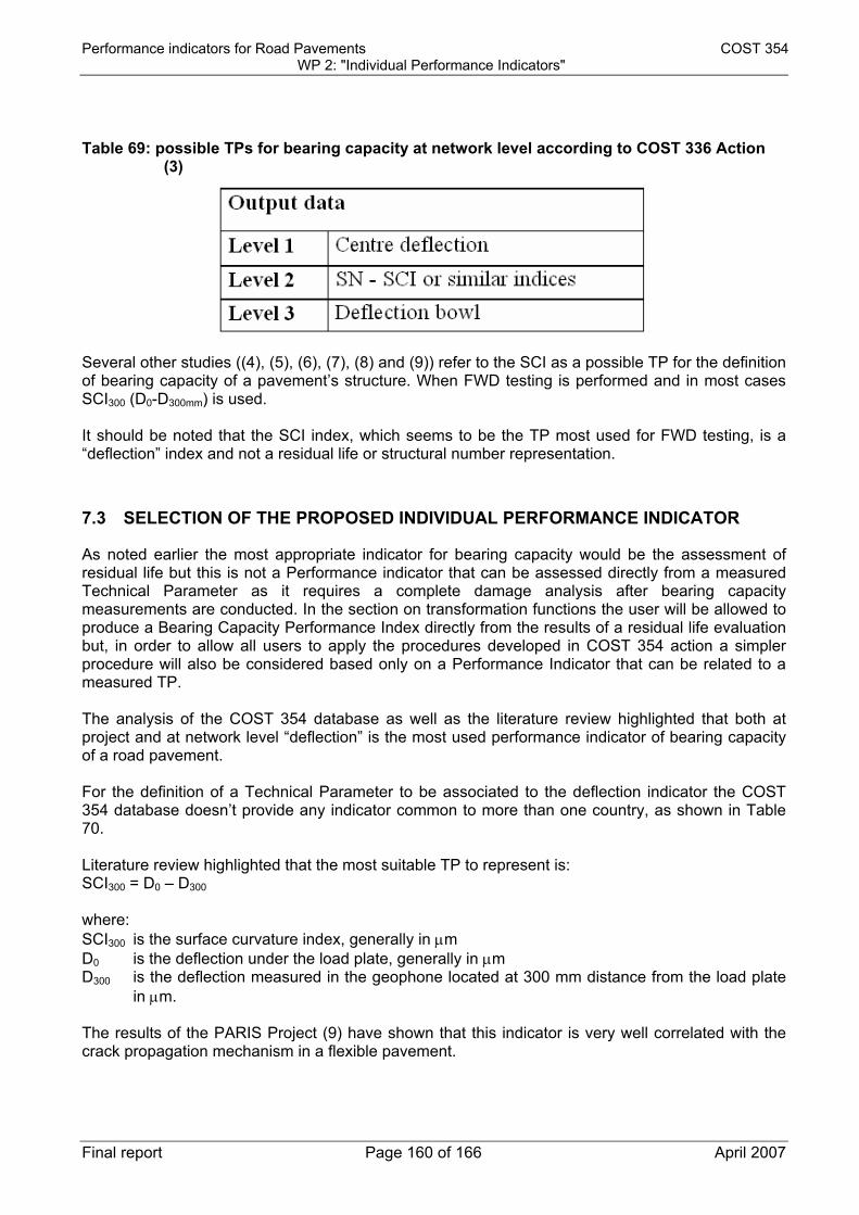
Performance indicators for Road Pavements COST 354 WP 2: "Individual Performance Indicators"
Final report Page 160 of 166 April 2007
Table 69: possible TPs for bearing capacity at network level according to COST 336 Action (3)
Several other studies ((4), (5), (6), (7), (8) and (9)) refer to the SCI as a possible TP for the definition of bearing capacity of a pavement’s structure. When FWD testing is performed and in most cases SCI300 (D0-D300mm) is used. It should be noted that the SCI index, which seems to be the TP most used for FWD testing, is a “deflection” index and not a residual life or structural number representation.
7.3 SELECTION OF THE PROPOSED INDIVIDUAL PERFORMANCE INDICATOR
As noted earlier the most appropriate indicator for bearing capacity would be the assessment of residual life but this is not a Performance indicator that can be assessed directly from a measured Technical Parameter as it requires a complete damage analysis after bearing capacity measurements are conducted. In the section on transformation functions the user will be allowed to produce a Bearing Capacity Performance Index directly from the results of a residual life evaluation but, in order to allow all users to apply the procedures developed in COST 354 action a simpler procedure will also be considered based only on a Performance Indicator that can be related to a measured TP. The analysis of the COST 354 database as well as the literature review highlighted that both at project and at network level “deflection” is the most used performance indicator of bearing capacity of a road pavement. For the definition of a Technical Parameter to be associated to the deflection indicator the COST 354 database doesn’t provide any indicator common to more than one country, as shown in Table 70. Literature review highlighted that the most suitable TP to represent is: SCI300 = D0 – D300 where: SCI300 is the surface curvature index, generally in μm D0 is the deflection under the load plate, generally in μm D300 is the deflection measured in the geophone located at 300 mm distance from the load plate
in μm. The results of the PARIS Project (9) have shown that this indicator is very well correlated with the crack propagation mechanism in a flexible pavement.

Performance indicators for Road Pavements COST 354 WP 2: "Individual Performance Indicators"
Final report Page 161 of 166 April 2007
This TP will therefore be selected in this section as the most suitable for the definition of the Performance Indicator “deflection”.
7.4 PROTOCOLS AND TEST METHODS FOR MEASURING THE PROPOSED INDIVIDUAL INDICATOR
As indicated above the PI is actually the deflection and therefore any of the data collection procedures described in COST354 database referred to this PI can be used. These are synthesised in Table 70.
Table 70: TP used in the cost 354 database to quantify the “deflection” PI
Country Abbr TP Unit TP Details of Data Collection
UK Df mm
The FWD produces a dynamic impulse load that simulates a moving wheel load. This information can in turn be used in a structural analysis to determine the bearing capacity, estimate expected life, and calculate an overlay requirement
AT DEF mm loading plate 30cm diameter, load 70kN, loading impact time 25 milliseconds
EL DI µ Based on COST 336 IT PD µ
FR dc µ
CH d mm
DK other
A weight system is dropped onto a set of springs creating a transient load pulse. The magnitude of the load plus surface deflections at different distances from the load centre are monitored
UK Def mm Measurement every 4m
PT D0 µ 7 deflection sensors; Peak load 78 kN; Flexible loading plate diameter 300 mm
ES D µ
The values are corrected by some coefficients depending on the measurement equipment, the humidity of the subgrade and the temperature
ES D µ
The values are corrected by some coefficients depending on the measurement equipment, the humidity of the subgrade and the temperature
CS D0 mm 2 B. beams for both wheel paths; pavement deflection under the heavy wheel load; FWD - 7 geophones
7.5 ASSESSMENT OF THE TRANSFORMATION FUNCTIONS
The final output of the procedure described in this section of the document is the definition of a Performance Index for bearing capacity (PI_B) in a 0 to 5 scale where 0 represents a very good condition and 5 a very bad one.

Performance indicators for Road Pavements COST 354 WP 2: "Individual Performance Indicators"
Final report Page 162 of 166 April 2007
If the user can provide a residual life for the specific section or network segment analysed the ratio of this residual life to the design life can be used to assess the bearing capacity index according to the graph in Figure 101.
0
1
2
3
4
5
0 0.1 0.2 0.3 0.4 0.5 0.6 0.7 0.8 0.9 1
PI_B
Residual life/Design life
PI_B=5⋅ (1‐Residual life/Design Life)
Figure 101: transfer function for Bearing Capacity Performance Index based on residual life If the SCI300 or another deflection indicator is used the user can either: - provide a Bearing Capacity Index value in a 0 to 5 scale based on their own transfer functions; - derive the Bearing Capacity Index value from a SCI300 value based on the transfer function
described below. The results of the STSM1 (Short Term Scientific Mission No. 1) of COST Action 354 (10) have shown that the two approaches are consistent in determining the structural condition of the pavement, both for flexible and semirigid structures. As a matter of fact the PARIS crack initiation model (9), based on the SCI300, value is extremely well correlated with the Belgian CRR indicator which rates the surface deterioration. According to Molenaar et al. (6) the vertical compressive strain at the top of the base layer (εb) that can be allowed to sustain 106 load repetitions is in the order of 630 to 1122 μm/m depending on the structural characteristics of the base material. This can then be transformed in a limiting value for SCI300 based on the equation:
log εb = 0.9962 + 0.8548 ⋅ log SCI300 provided in the same paper. This leads us to consider a limiting value of SCI300 between 129 μm (for weak base materials) and 253 μm (for strong base materials). Assuming a linear relationship between the PI_B and the SCI300 limits, a transfer function can be drawn for weak and strong base materials, as shown in Figure 102.

Performance indicators for Road Pavements COST 354 WP 2: "Individual Performance Indicators"
Final report Page 163 of 166 April 2007
0
1
2
3
4
5
0 50 100 150 200 250
PI_
B
SCI300 [μm]
PI_B=SCI300/253 (for strong base)
PI_B=SCI300/129(for weak base)
Figure 102: transfer function for bearing capacity index based on SCI300 for weak and strong
base materials
7.6 REFERENCES
1. M.S.Snaith, The Quantification and Specification of Network Condition, still to be published;
2. J.J. Ortiz-Garcia, M.S. Snaith, V.T. Tachtsi, Estimation of road network total maintenance cost Proc. Instn. Civ. Engrs. Mun. Engr N. 133 June 1999 pages 93-99 – Paper 11908;
3. COST 336 Falling Weight Deflectometer Final Report of the Action (http://cordis.europa.eu/cost-transport/src/cost-336.htm);
4. Z. Zhang, G. Claros, L. Manuel, I. Damnjanovic Evaluation of the pavement structural condition at network level using falling weight deflectometer (fwd) data Presentation at the Transportation Research Board 2003
5. IRELAND Guidelines on the Depth of Overlay to be used on Rural Non-National Roads (http://www.environ.ie);
6. A.A.A. Molenaar, L.J.M. Houben, A.A. Alemgena Estimation of Maximum Strains in Road Bases for Pavement Performance Predictions Mairepav 2003 Conference Proceedings;
7. L-G. Wagberg Utveckling av nedbrytnins-modeller VTI meddelande 916 – 2001 (in Swedish with abstract in English)
8. E. Boo, E. Karlsson Utvärdening av olika bärighetsmått University of Lunds (Sweden) Thesis Highway Engineering 39 – 2005 (in Swedish with abstract in English)
9. PARIS Project “Performance analysis of road infrastructure”, Published by the EU, 1999 ISBN 92-828-7827-9
10. S. Fontul, “Structural Performance Indicator Based on GPR and Bearing Capacity Measurements” presentation of the results of the COST 354 STSM1, 2006 (internal document)

Performance indicators for Road Pavements COST 354 WP 2: "Individual Performance Indicators"
Final report Page 164 of 166 April 2007
SECTION 8: SUMMARY AND CONCLUSIONS
8.1 SYNTHESIS OF SELECTED TP, PERFORMANCE INDICES AND TRANSFER FUNCTIONS
Based on the analysis of each single PI described above a set of “selected” PIs have been identified and are summarized in Table 71. For each of the selected PIs the transfer function that leads from the Technical Parameters (TP) to the unitless PI is also included in Table 71. As it can be seen in some cases there is not a single transfer function as this can depend on the type of road network, on the type of TP used or on the strength of the structure. For longitudinal evenness a “more restrictive” and a “less restrictive” function have been provided to give the user an idea of the range of different solutions adopted in practice. It is important to note, that it is not mandatory to use the proposed TP as the basis for calculating the Performance Index. If the user is able to provide a transformation function for a different TP, providing a PI on the 0 to 5 scale (0 being good and 5 poor), this can be used in the general indices that will be developed in WP 4 of COST 354 Action instead of the proposed index and transfer function. In the same manner the user can adopt the proposed TP but a different transfer function as compared to those listed in Table 71.
Table 71: synthesis of the selected indicators
PERFORMANCE INDICATOR
TP PI_index TRANSFER FUNCTION
Longitudinal evenness
IRI (mm/m) PI_evenness (PI_E)
PI_E = MAX(0; MIN (5; (0.1733·IRI2+0.7142·IRI-0.0316))) (more restrictive)
PI_E = MAX(0; MIN (5; 0.816·IRI)) (less restrictive)
Transverse evenness
Rut depth [RD] (mm)
PI_rutting (PI_R) For all road classes: PI_R = MAX(0; MIN (5; (-0.0016·RD2 + 0.2187·RD))) For motorways and primary roads: PI_R = MAX(0; MIN (5; (-0.0015·RD2 + 0.2291·RD))) For secondary and local roads: PI_R = MAX(0; MIN (5; (-0.0023·RD2 + 0.2142·RD)))
Skid resistance SFC (0 to 1) at 60 km/h LFC (0 to 1) at 50 km/h
PI_friction (PI_F) PI_F = MAX(0; MIN (5;(-17.600*SFC+11.205))) PI_F = MAX(0; MIN (5;(-13.875*LFC+9.338)))
Macrotexture MPD (mm) PI_macrotexture (PI_T)
For motorways and primary roads: PI_T = MAX(0; MIN (5;(6.6 – 5.3·MPD))) For secondary roads: PI_T = MAX(0; MIN (5;(7.0 – 6.9·MPD)))
Bearing capacity • Residual life/ Design life
PI_bearing capacity (PI_B)
PI_B = MAX(0; MIN (5;(5·(1- R/D))))

Performance indicators for Road Pavements COST 354 WP 2: "Individual Performance Indicators"
Final report Page 165 of 166 April 2007
[R/D] (if available)
• SCI300 (µm)
PI_B = MAX(0; MIN (5;(SCI300/129))) for weak bases PI_B = MAX(0; MIN (5;(SCI300/253))) for strong bases
Noise - - - Air pollution - - -
8.2 FUTURE PERSPECTIVES AND RESEARCH NEEDS
The evaluation of the data contained in the COST 354 database has highlighted some basic problems that could be addressed by additional research or that can lead to a change in the selection of the PIs in a close future. The key issues that arose during the work can be summarized as follows: - in most cases the most used indicators are “conventional” ones (such as IRI and MPD) but this
does not mean that these are the best ones to represent the given performance indicator. Most of the “new” indicators are still in a research stage or used only by a limited number of countries and this lead to the decision that it was not possible to select them as the “proposed PI”. The use of these indicators should be encouraged in order to move to these PIs in the near future;
- the use of 0 to 5 Indices are quite uncommon for most PIs and this lead to the need to define a transfer function based on very limited data (as for the macrotexture indicator) or none (as for the bearing capacity indicator);
- some PIs have very limited data (noise and environmental issues) and this, at this stage, doesn’t allow to define a 0 to 5 scale Performance Index. In this area there is probably a specific research need.
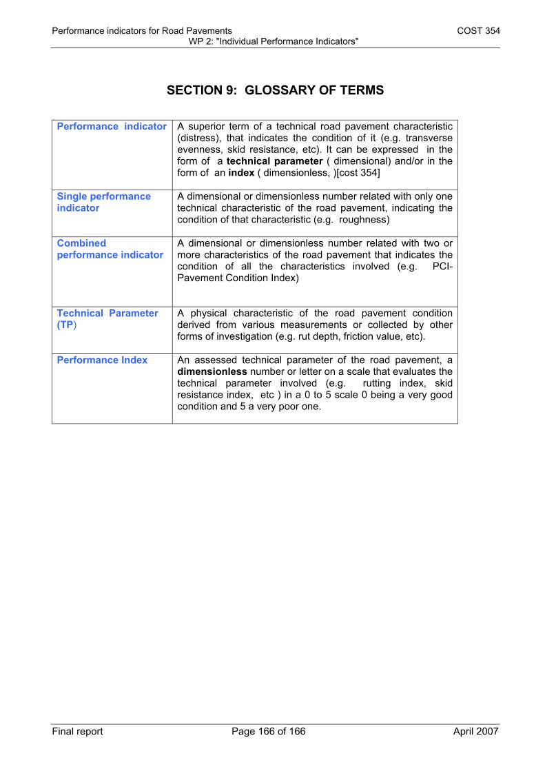
Performance indicators for Road Pavements COST 354 WP 2: "Individual Performance Indicators"
Final report Page 166 of 166 April 2007
SECTION 9: GLOSSARY OF TERMS
Performance indicator A superior term of a technical road pavement characteristic
(distress), that indicates the condition of it (e.g. transverse evenness, skid resistance, etc). It can be expressed in the form of a technical parameter ( dimensional) and/or in the form of an index ( dimensionless, )[cost 354]
Single performance indicator
A dimensional or dimensionless number related with only one technical characteristic of the road pavement, indicating the condition of that characteristic (e.g. roughness)
Combined performance indicator
A dimensional or dimensionless number related with two or more characteristics of the road pavement that indicates the condition of all the characteristics involved (e.g. PCI- Pavement Condition Index)
Technical Parameter (TP)
A physical characteristic of the road pavement condition derived from various measurements or collected by other forms of investigation (e.g. rut depth, friction value, etc).
Performance Index An assessed technical parameter of the road pavement, a dimensionless number or letter on a scale that evaluates the technical parameter involved (e.g. rutting index, skid resistance index, etc ) in a 0 to 5 scale 0 being a very good condition and 5 a very poor one.