Embed Size (px)
Citation preview
COS 461 Computer NetworksLecture 4: Hubs, Switches, and
Routers
Kyle JamiesonFall 2020
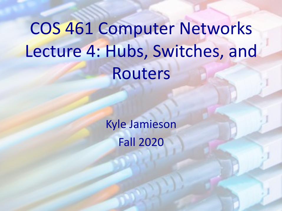
Today: Hubs, Switches, and Routers, Oh My!
2
HTTP
TCP
IP
Ethernetinterface
HTTP
TCP
IP
Ethernetinterface
IP IP
Ethernetinterface
Ethernetinterface
SONETinterface
SONETinterface
host host
router router
HTTP message
TCP segment
IP packet IP packetIP packet
Application
Transport
Network
Link
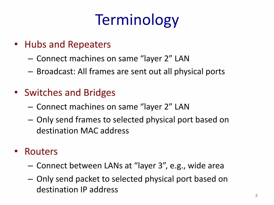
Terminology• Hubs and Repeaters
– Connect machines on same “layer 2” LAN– Broadcast: All frames are sent out all physical ports
• Switches and Bridges– Connect machines on same “layer 2” LAN– Only send frames to selected physical port based on
destination MAC address
• Routers– Connect between LANs at “layer 3”, e.g., wide area– Only send packet to selected physical port based on
destination IP address3
“Layer 2”Hubs and Switches
4
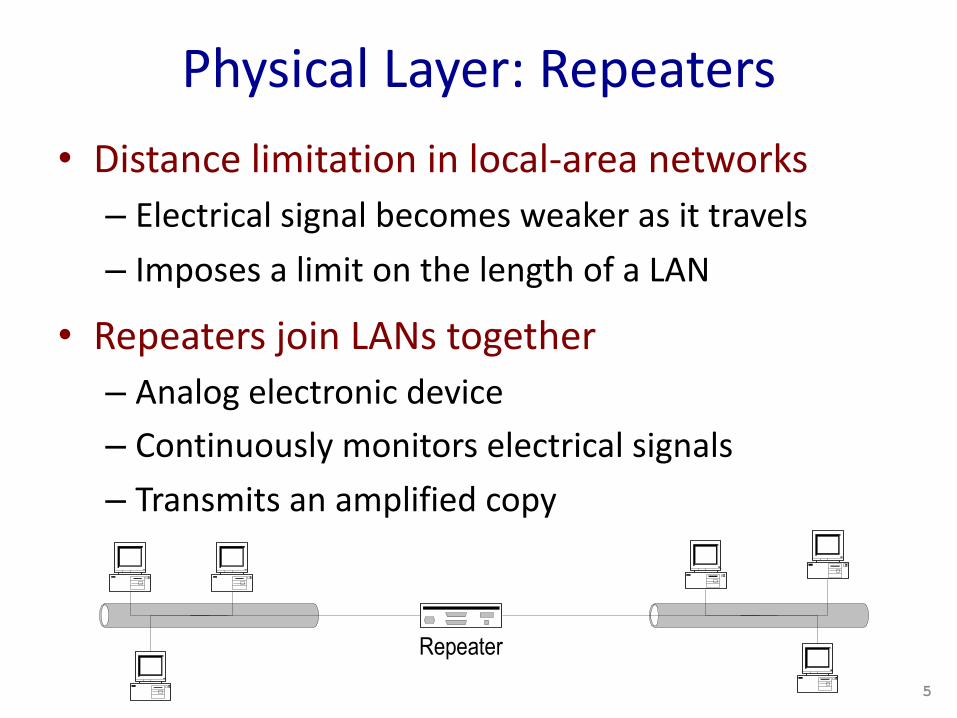
Physical Layer: Repeaters• Distance limitation in local-area networks– Electrical signal becomes weaker as it travels– Imposes a limit on the length of a LAN
• Repeaters join LANs together– Analog electronic device– Continuously monitors electrical signals– Transmits an amplified copy
Repeater
5
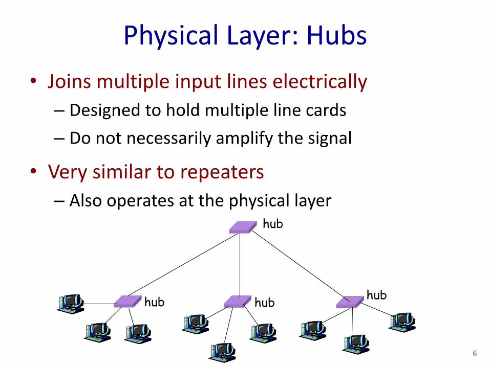
Physical Layer: Hubs• Joins multiple input lines electrically– Designed to hold multiple line cards– Do not necessarily amplify the signal
• Very similar to repeaters– Also operates at the physical layer
hub hub hub
hub
6
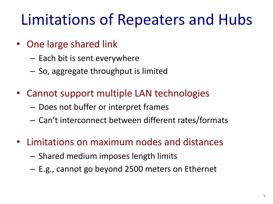
Limitations of Repeaters and Hubs• One large shared link
– Each bit is sent everywhere– So, aggregate throughput is limited
• Cannot support multiple LAN technologies– Does not buffer or interpret frames– Can’t interconnect between different rates/formats
• Limitations on maximum nodes and distances– Shared medium imposes length limits– E.g., cannot go beyond 2500 meters on Ethernet
7
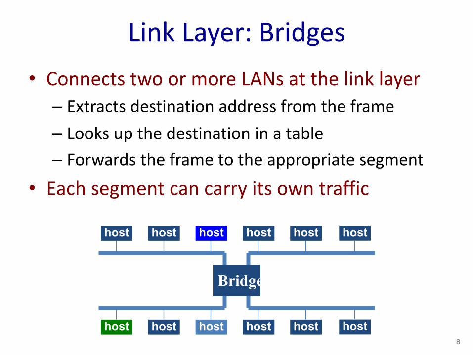
Link Layer: Bridges• Connects two or more LANs at the link layer– Extracts destination address from the frame– Looks up the destination in a table– Forwards the frame to the appropriate segment
• Each segment can carry its own traffic
host host host host host
host host host host host
host
host
Bridge
8
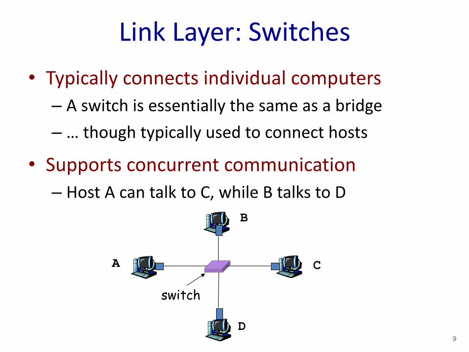
Link Layer: Switches• Typically connects individual computers– A switch is essentially the same as a bridge– … though typically used to connect hosts
• Supports concurrent communication– Host A can talk to C, while B talks to D
switch
A
B
C
D9
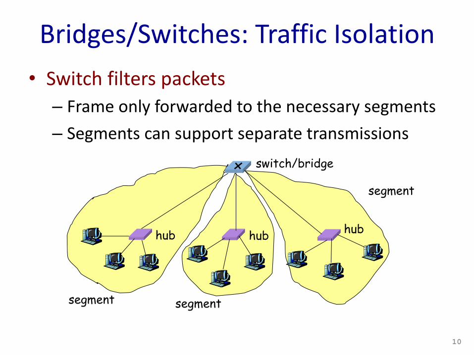
Bridges/Switches: Traffic Isolation• Switch filters packets– Frame only forwarded to the necessary segments – Segments can support separate transmissions
hub hub hub
switch/bridge
segment segment
segment
10
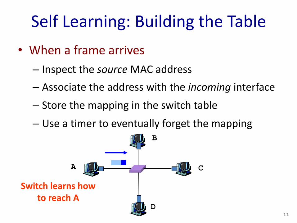
Self Learning: Building the Table• When a frame arrives– Inspect the source MAC address– Associate the address with the incoming interface– Store the mapping in the switch table– Use a timer to eventually forget the mapping
A
B
C
D
Switch learns how to reach A
11
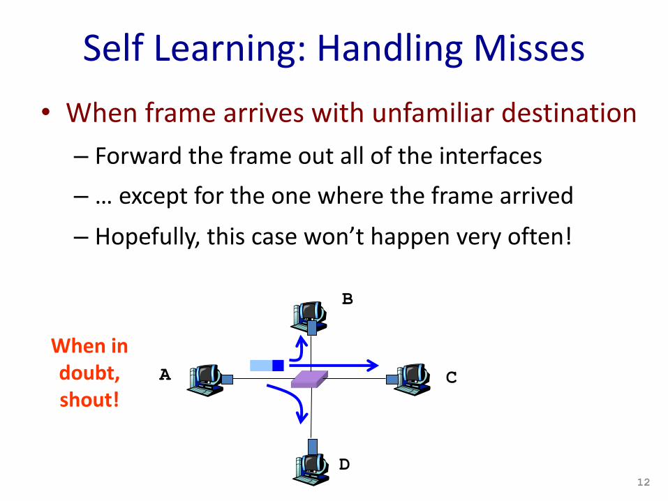
Self Learning: Handling Misses• When frame arrives with unfamiliar destination– Forward the frame out all of the interfaces– … except for the one where the frame arrived– Hopefully, this case won’t happen very often!
When in doubt, shout!
12
A
B
C
D
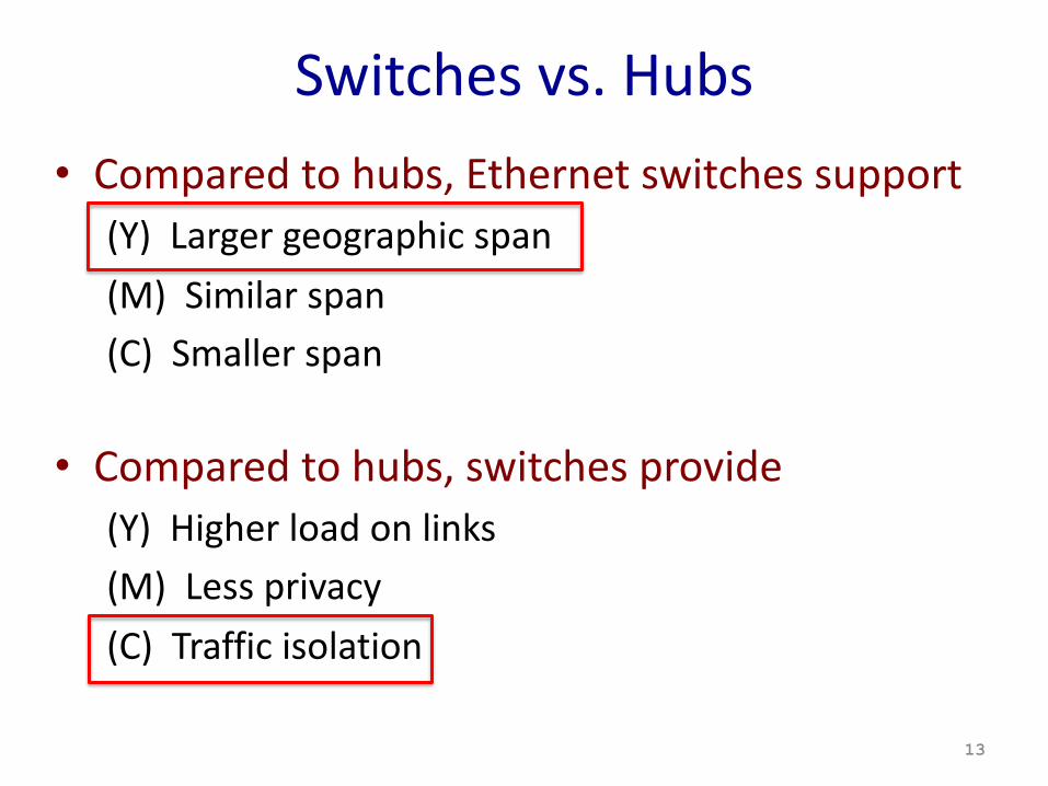
Switches vs. Hubs• Compared to hubs, Ethernet switches support
(Y) Larger geographic span(M) Similar span(C) Smaller span
• Compared to hubs, switches provide(Y) Higher load on links(M) Less privacy(C) Traffic isolation
13
Routers: Looking closer…
14
Basic Router Architecture
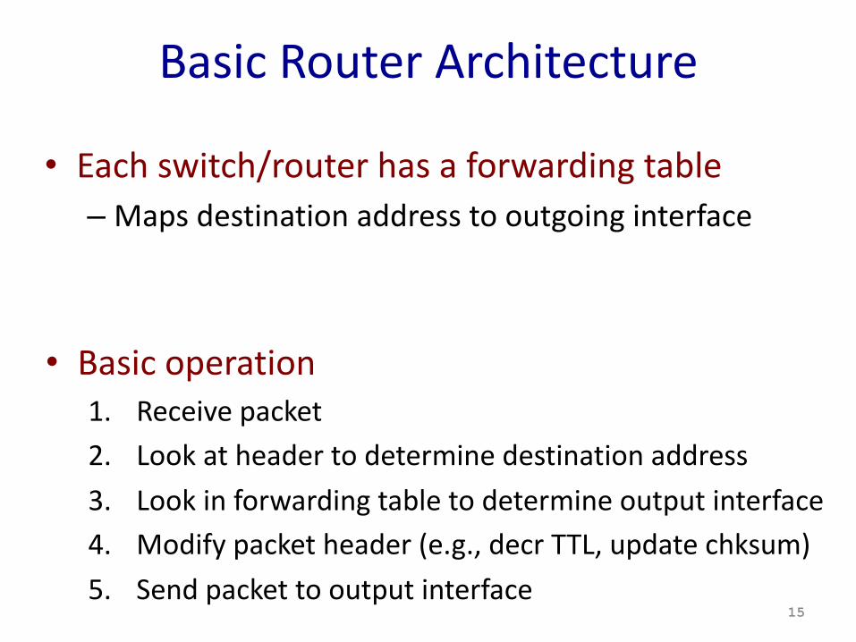
• Each switch/router has a forwarding table– Maps destination address to outgoing interface
15
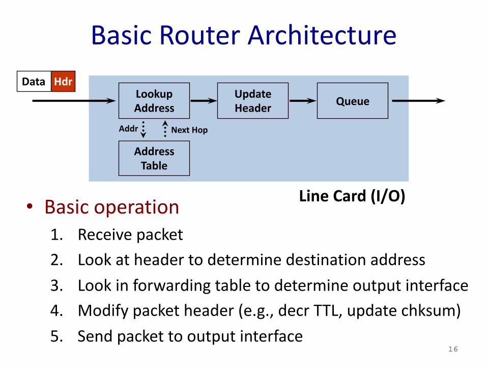
• Basic operation1. Receive packet2. Look at header to determine destination address3. Look in forwarding table to determine output interface4. Modify packet header (e.g., decr TTL, update chksum)5. Send packet to output interface
• Basic operation1. Receive packet2. Look at header to determine destination address3. Look in forwarding table to determine output interface4. Modify packet header (e.g., decr TTL, update chksum)5. Send packet to output interface
16
LookupAddress
Data Hdr
Basic Router Architecture
AddressTable
UpdateHeader Queue
Addr Next Hop
Line Card (I/O)
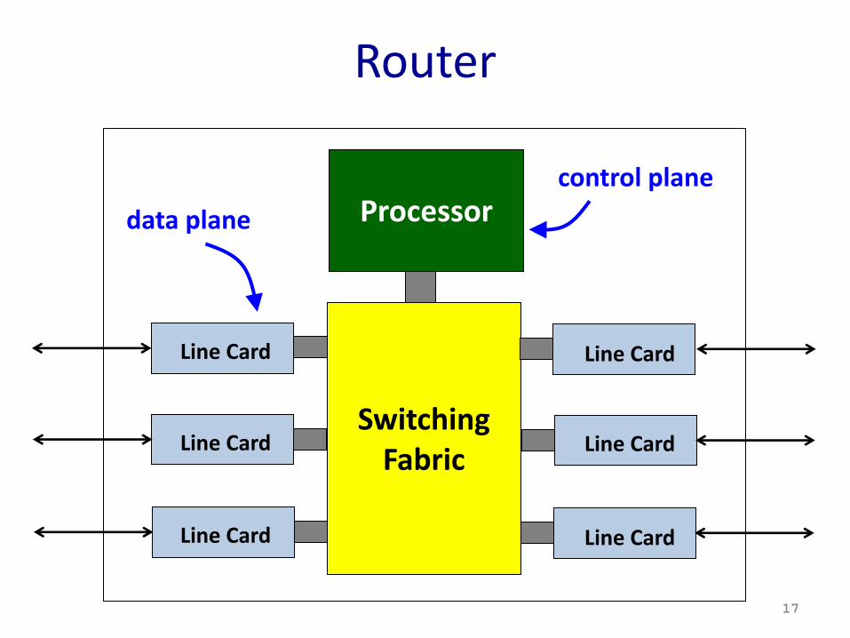
Router
SwitchingFabric
Processor
Line Card
Line Card
Line Card
Line Card
Line Card
Line Card
data planecontrol plane
17
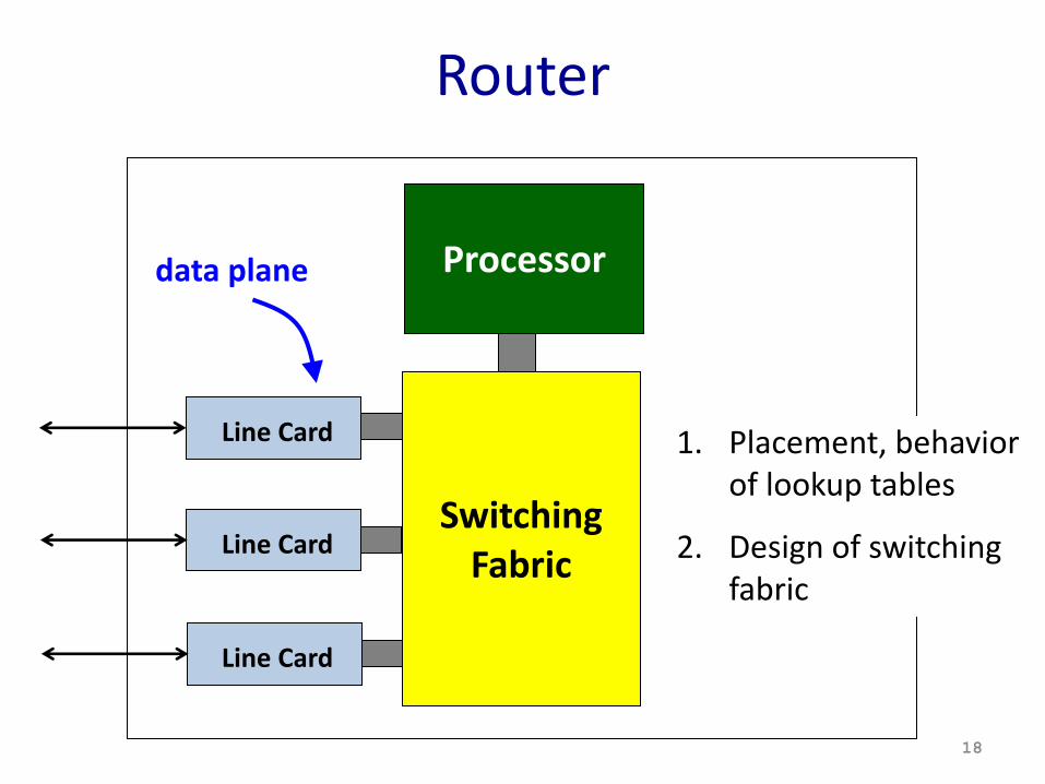
Router
SwitchingFabric
Processor
Line Card
Line Card
Line Card
data plane
18
1. Placement, behavior of lookup tables
2. Design of switching fabric
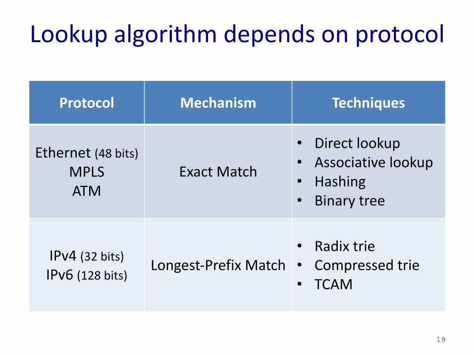
Lookup algorithm depends on protocol
19
Protocol Mechanism Techniques
Ethernet (48 bits)MPLSATM
Exact Match
• Direct lookup• Associative lookup• Hashing• Binary tree
IPv4 (32 bits)IPv6 (128 bits)
Longest-Prefix Match• Radix trie• Compressed trie• TCAM
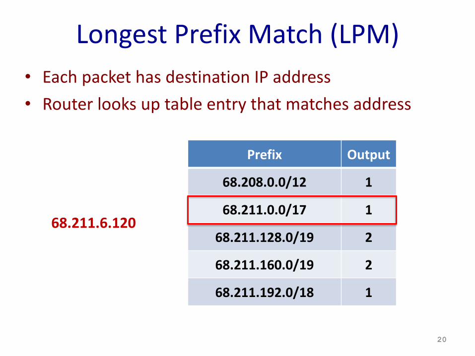
Longest Prefix Match (LPM)• Each packet has destination IP address• Router looks up table entry that matches address
20
Prefix Output
68.208.0.0/12 1
68.211.0.0/17 1
68.211.128.0/19 2
68.211.160.0/19 2
68.211.192.0/18 1
68.211.6.120
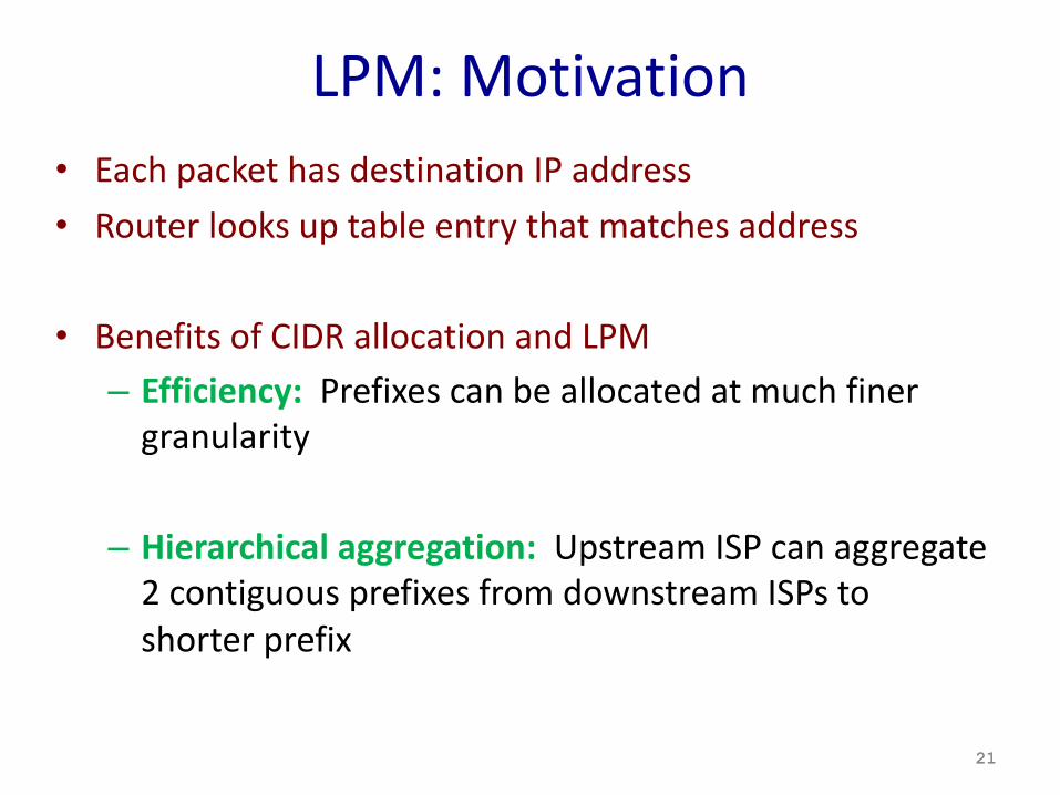
LPM: Motivation• Each packet has destination IP address• Router looks up table entry that matches address
• Benefits of CIDR allocation and LPM– Efficiency: Prefixes can be allocated at much finer
granularity
– Hierarchical aggregation: Upstream ISP can aggregate 2 contiguous prefixes from downstream ISPs to shorter prefix
21
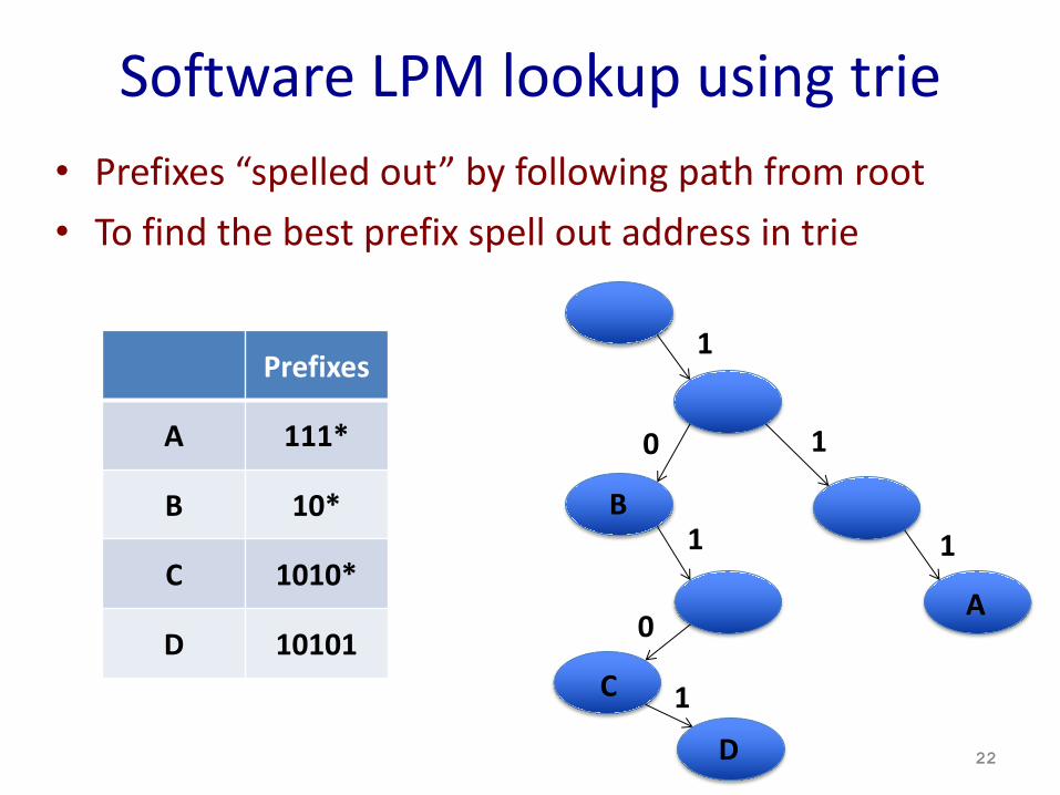
Software LPM lookup using trie• Prefixes “spelled out” by following path from root• To find the best prefix spell out address in trie
22
Prefixes
A 111*
B 10*
C 1010*
D 10101
1
1
1
0
1
0
1
A
B
C
D
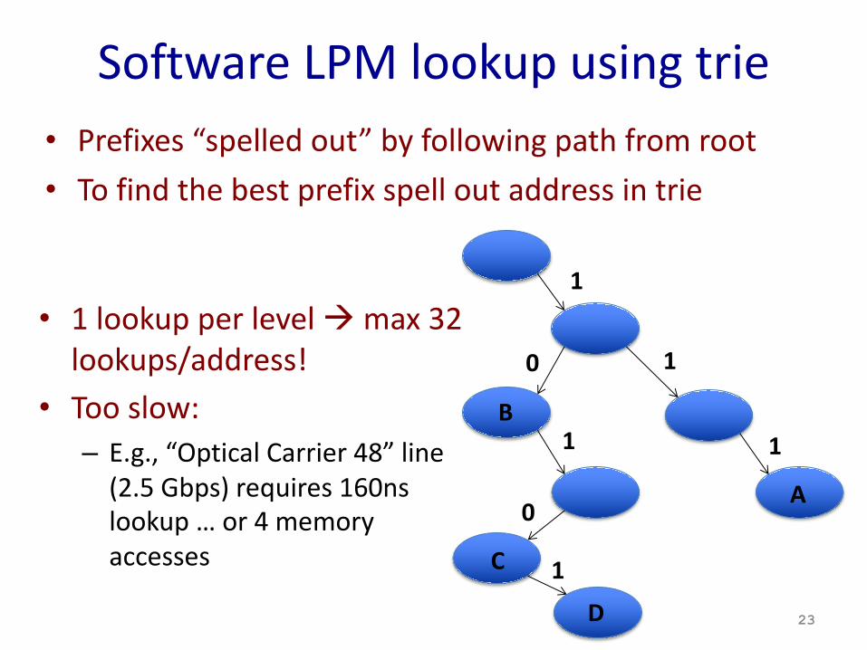
Software LPM lookup using trie• Prefixes “spelled out” by following path from root• To find the best prefix spell out address in trie
23
1
1
1
0
1
0
1
A
B
C
D
• 1 lookup per level à max 32 lookups/address!
• Too slow:– E.g., “Optical Carrier 48” line
(2.5 Gbps) requires 160ns lookup … or 4 memory accesses
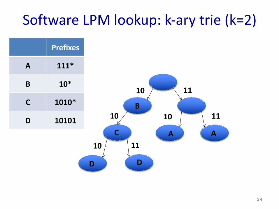
Software LPM lookup: k-ary trie (k=2)
24
11
1110
10
Prefixes
A 111*
B 10*
C 1010*
D 10101
10
B
A A11
10
C
D D
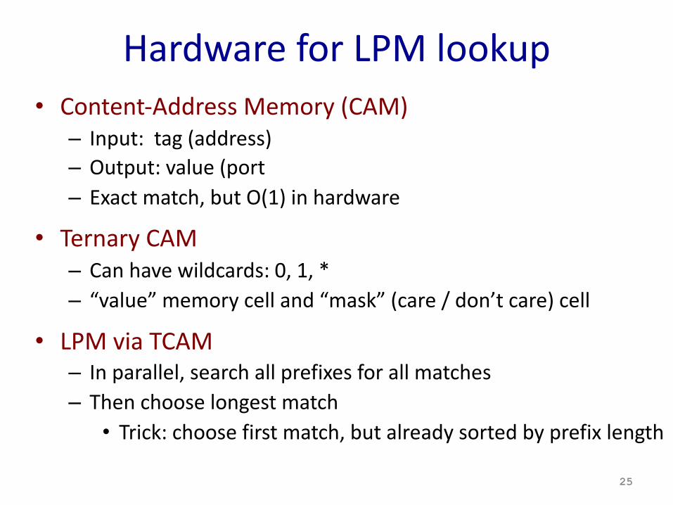
Hardware for LPM lookup• Content-Address Memory (CAM)
– Input: tag (address)– Output: value (port– Exact match, but O(1) in hardware
• Ternary CAM– Can have wildcards: 0, 1, * – “value” memory cell and “mask” (care / don’t care) cell
• LPM via TCAM– In parallel, search all prefixes for all matches– Then choose longest match
• Trick: choose first match, but already sorted by prefix length
25
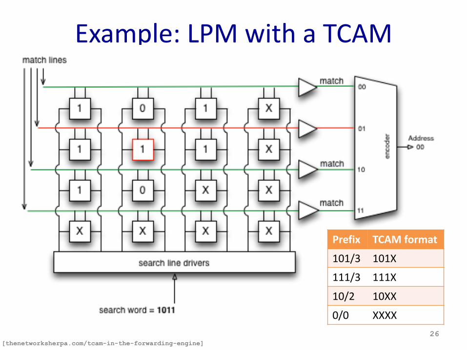
Example: LPM with a TCAM
26[thenetworksherpa.com/tcam-in-the-forwarding-engine]
Prefix TCAM format
101/3 101X
111/3 111X
10/2 10XX
0/0 XXXX
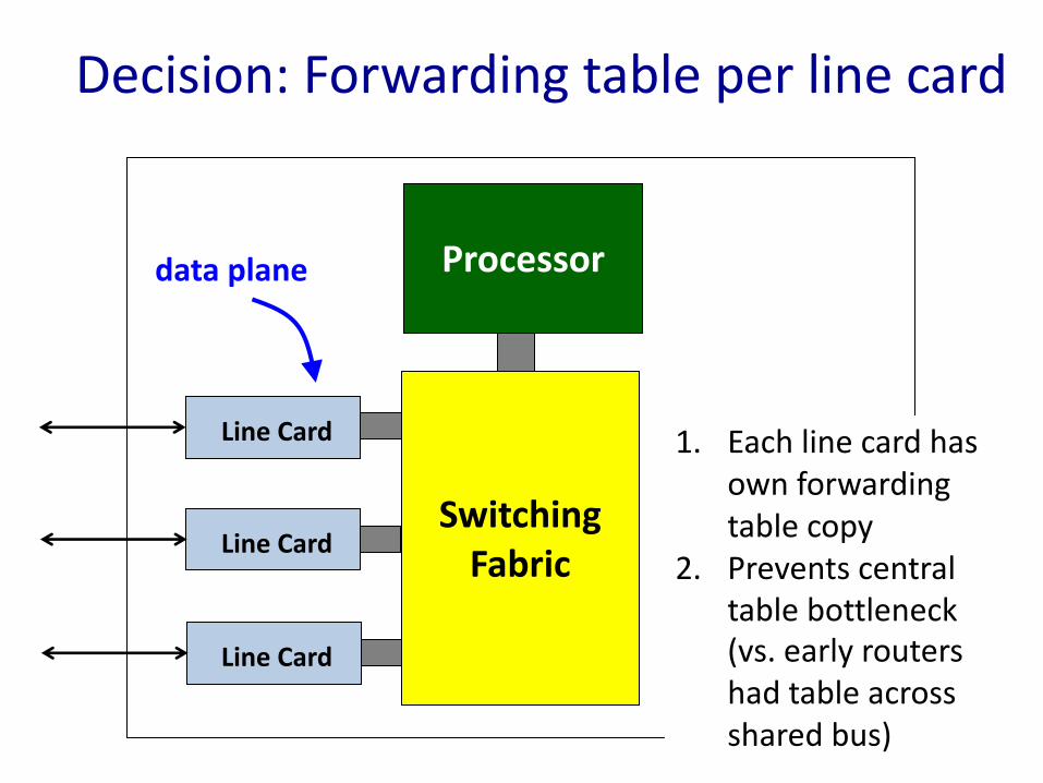
Decision: Forwarding table per line card
SwitchingFabric
Processor
Line Card
Line Card
Line Card
data plane
27
1. Each line card has own forwarding table copy
2. Prevents central table bottleneck (vs. early routers had table across shared bus)
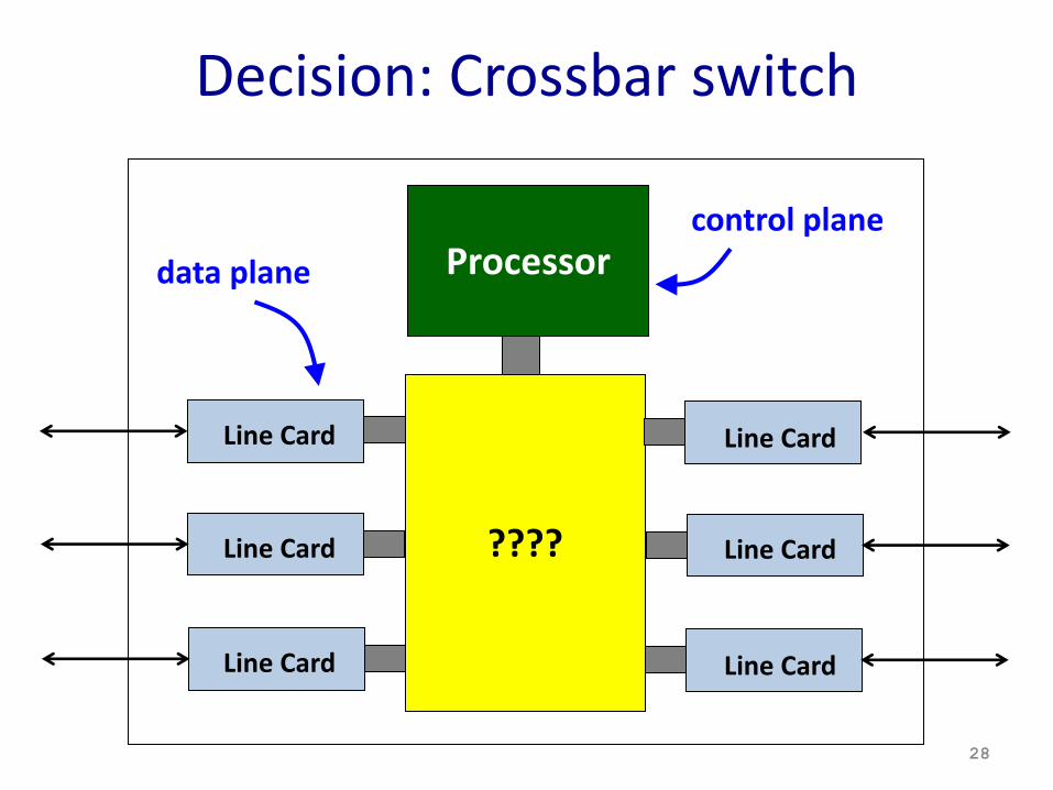
Decision: Crossbar switch
????
Processor
Line Card
Line Card
Line Card
Line Card
Line Card
Line Card
data planecontrol plane
28
Decision: Crossbar switch• Shared bus– Only one input can speak to one output at a time
• Crossbar switch / switched backplane– Input / output pairs that don’t compete can send
in same timeslot
29
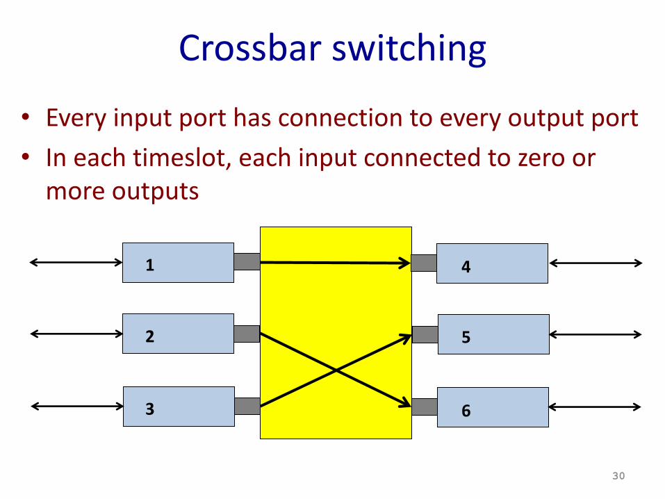
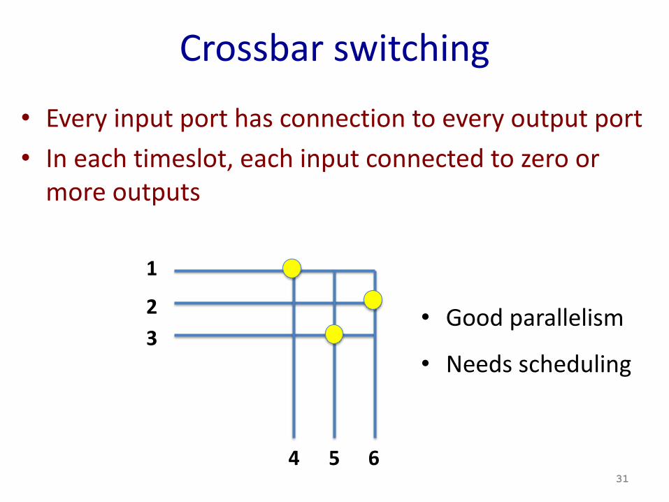
Crossbar switching
• Every input port has connection to every output port• In each timeslot, each input connected to zero or
more outputs
30
1
2
3
4
5
6
Crossbar switching
• Every input port has connection to every output port• In each timeslot, each input connected to zero or
more outputs
31
1
23
4 5 6
• Good parallelism
• Needs scheduling
Everything gets complicated…
32
1
2
3
4
5
6
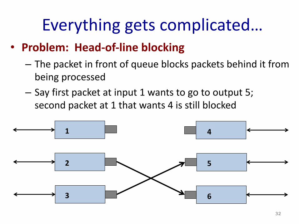
• Problem: Head-of-line blocking– The packet in front of queue blocks packets behind it from
being processed– Say first packet at input 1 wants to go to output 5;
second packet at 1 that wants 4 is still blocked
Everything gets complicated…
33
1
2
3
4
5
6
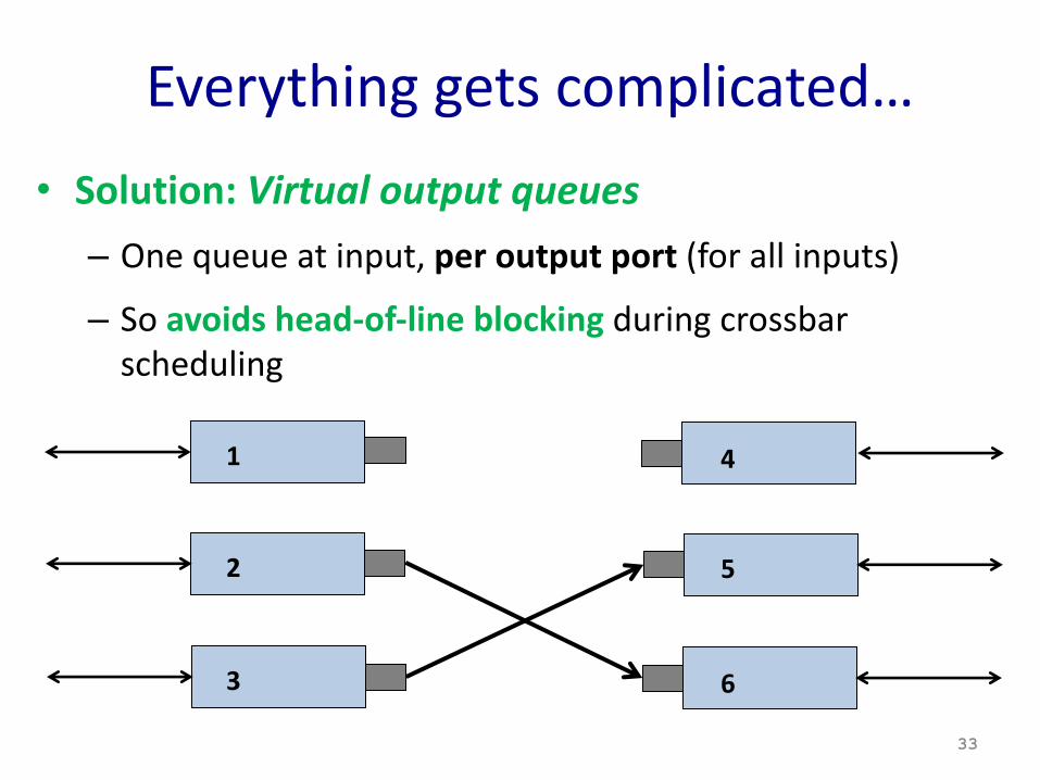
• Solution: Virtual output queues– One queue at input, per output port (for all inputs)
– So avoids head-of-line blocking during crossbar scheduling
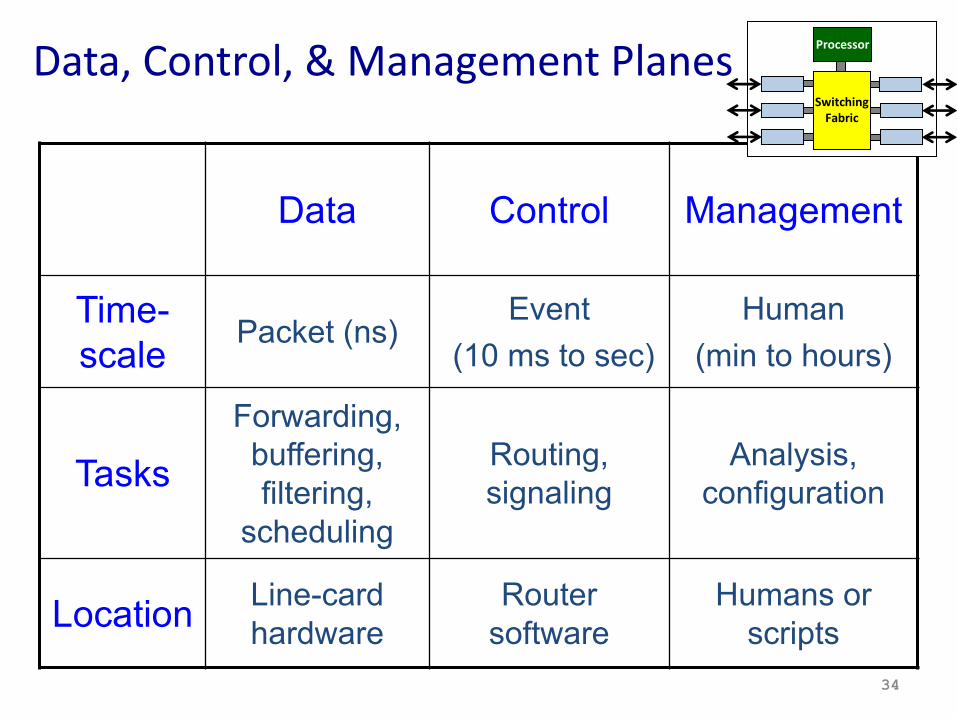
Data Control Management
Time-scale Packet (ns)
Event(10 ms to sec)
Human (min to hours)
TasksForwarding,
buffering, filtering,
scheduling
Routing, signaling
Analysis, configuration
Location Line-card hardware
Router software
Humans or scripts
Data, Control, & Management Planes
34
SwitchingFabric
Processor
35
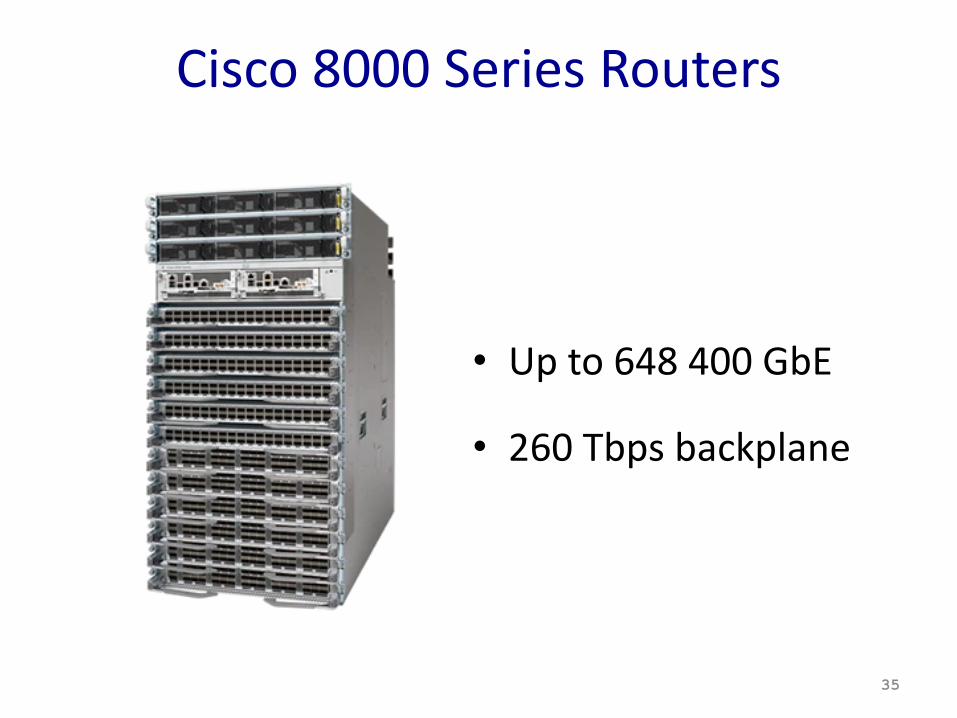
Cisco 8000 Series Routers
• Up to 648 400 GbE
• 260 Tbps backplane
Conclusions• Physical devices sharing L2 & L3 networks have many
common features– Forward table lookups– Queueing and backplane switching– Fast vs. slow paths
• Switches and routers separate routing decisions (control plane) from forwarding actions (data plane)
• High speed necessitates innovation– Specialized hardware – Software algorithms
36