Embed Size (px)
DESCRIPTION
Corso tecnico completo EPS 2012 inglese
Citation preview

Technical course
Technical course
REV.10B
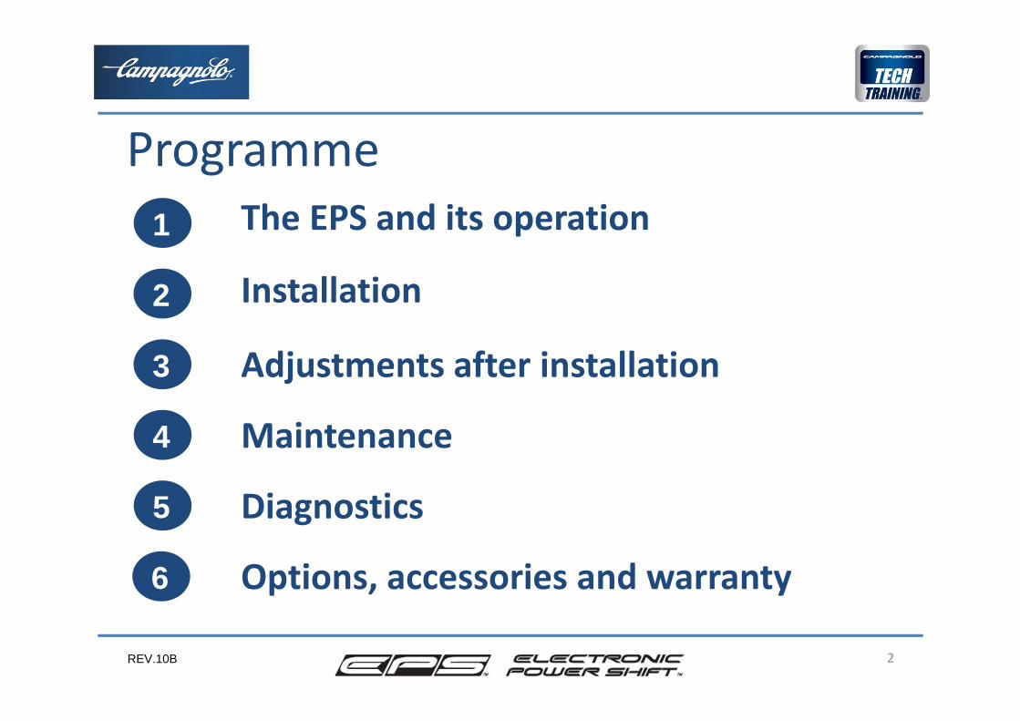
Programme
2
1
2
5
4
3
The EPS and its operation
Installation
Diagnostics
Options, accessories and warranty6
Maintenance
Adjustments after installation
REV.10B
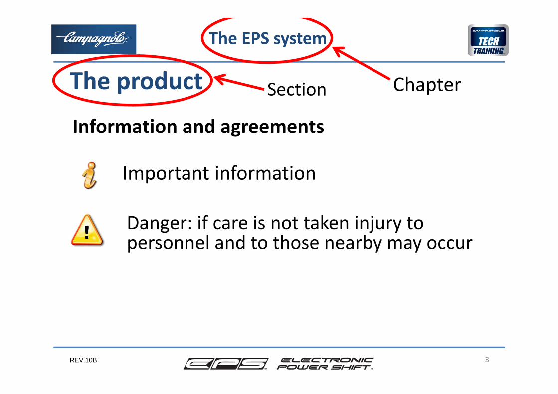
Important information
3
The EPS system
The product
Danger: if care is not taken injury to personnel and to those nearby may occur
Information and agreements
Section Chapter
REV.10B
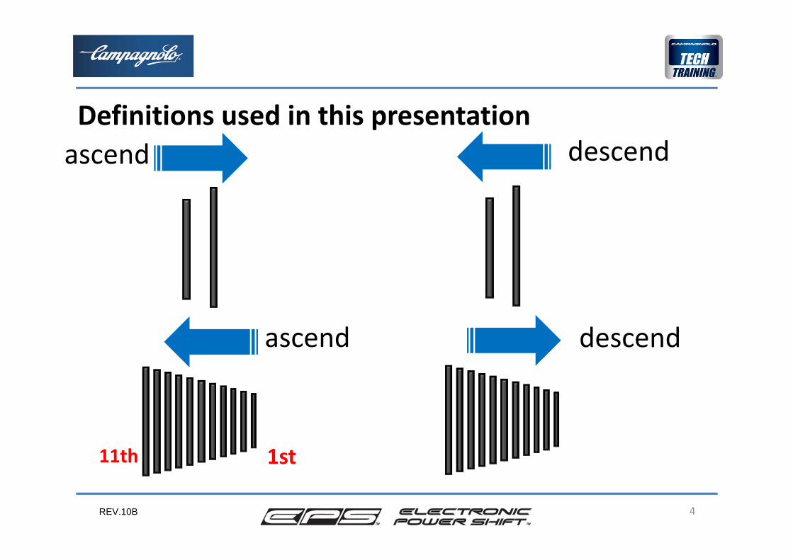
ascend
4
Definitions used in this presentationascend descend
descend
1st11th
REV.10B 5
12
4
3
5
The EPS and its operation
• The product• Operation on the road• System components• Customer adjustments
6

REV.10B
EPS, Electronic Power Shift, is the 11 speedelectronic drivetrain system conceived, built and marketed by Campagnolo.2 versions are available:
6
The EPS system
The product
REV.10B
The requests that the cyclist makes through the levers of the two controllers located on the handlebar are received by the electronic system. This system, with some optimisations, implements the requests, activating the rear and front derailleurs through electric motors.
Simultaneously the electronic system verifies that the rear and front derailleurs move correctly and reaches the required position.
The system also carries out other functions which we will discuss later.
7
The EPS system
Operation on the road
REV.10B
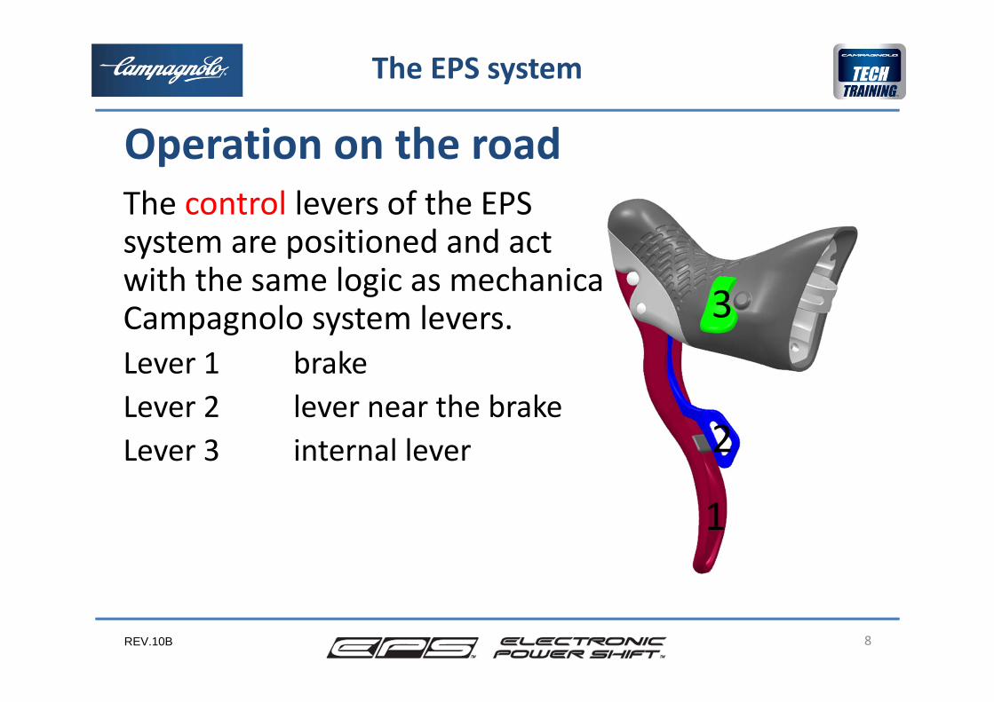
The control levers of the EPS system are positioned and act with the same logic as mechanical Campagnolo system levers.Lever 1 brakeLever 2 lever near the brakeLever 3 internal lever
8
The EPS system
Operation on the road
3
1
2
REV.10B
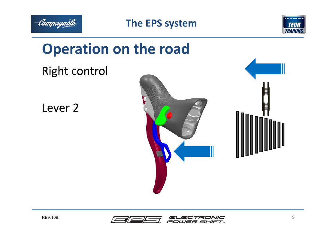
Right control
Lever 2
9
The EPS system
Operation on the road
REV.10B
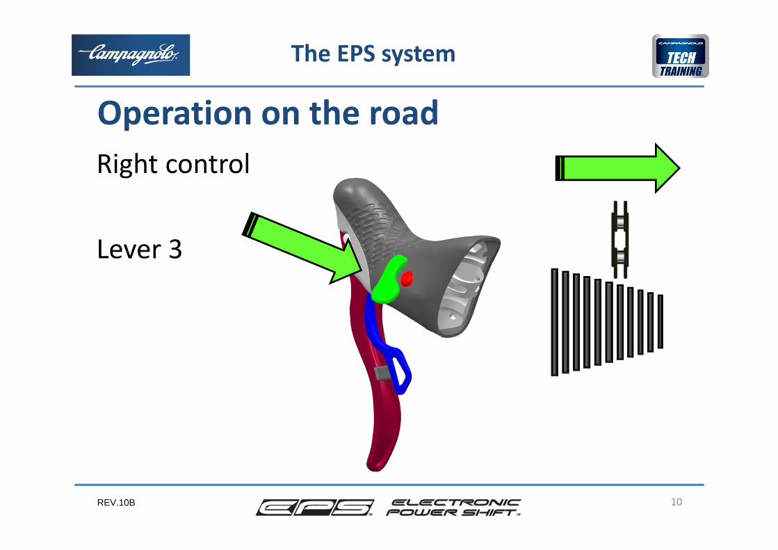
Right control
Lever 3
10
The EPS system
Operation on the road
REV.10B
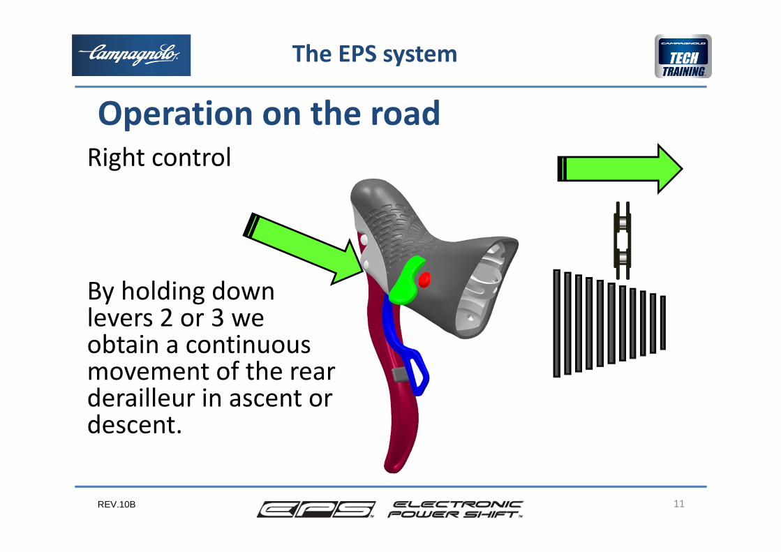
Right control
By holding down levers 2 or 3 we obtain a continuous movement of the rear derailleur in ascent or descent.
11
The EPS system
Operation on the road
REV.10B
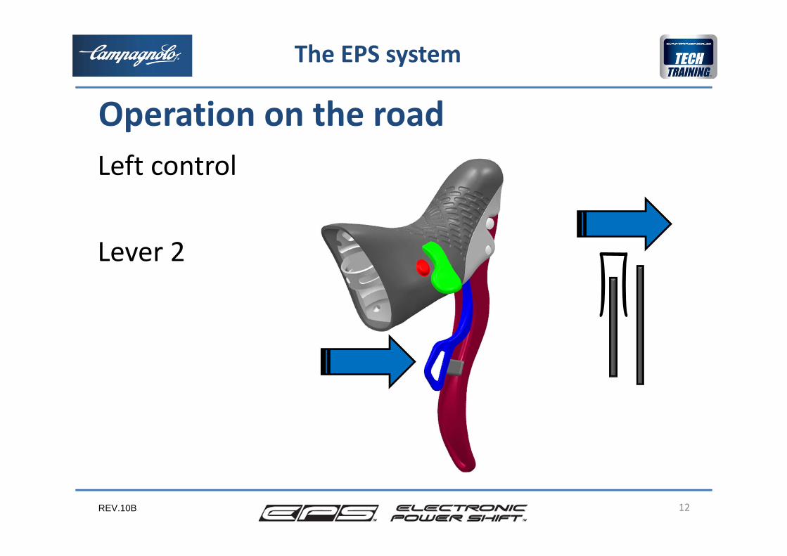
Left control
Lever 2
12
The EPS system
Operation on the road
REV.10B 13
The EPS system
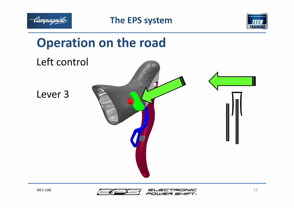
Operation on the road Left control
Lever 3
REV.10B
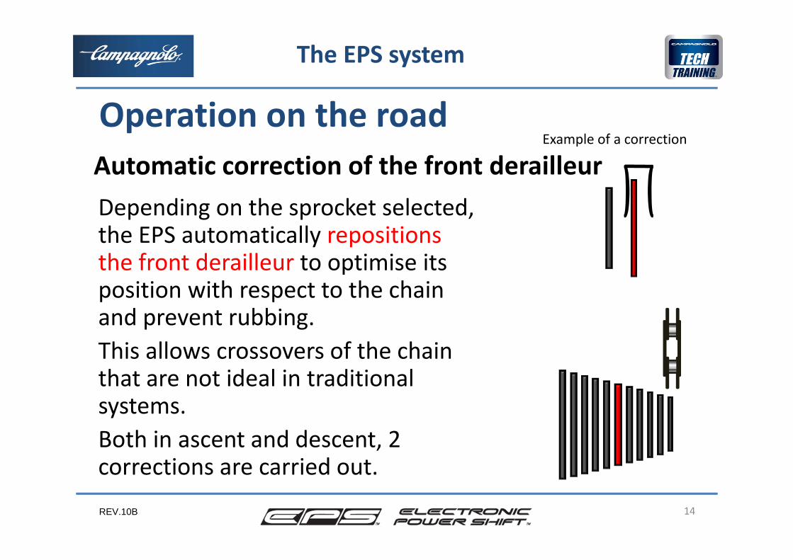
Depending on the sprocket selected, the EPS automatically repositions the front derailleur to optimise its position with respect to the chain and prevent rubbing.This allows crossovers of the chain that are not ideal in traditional systems.Both in ascent and descent, 2 corrections are carried out.
14
The EPS system
Operation on the road Automatic correction of the front derailleur
Example of a correction
REV.10B
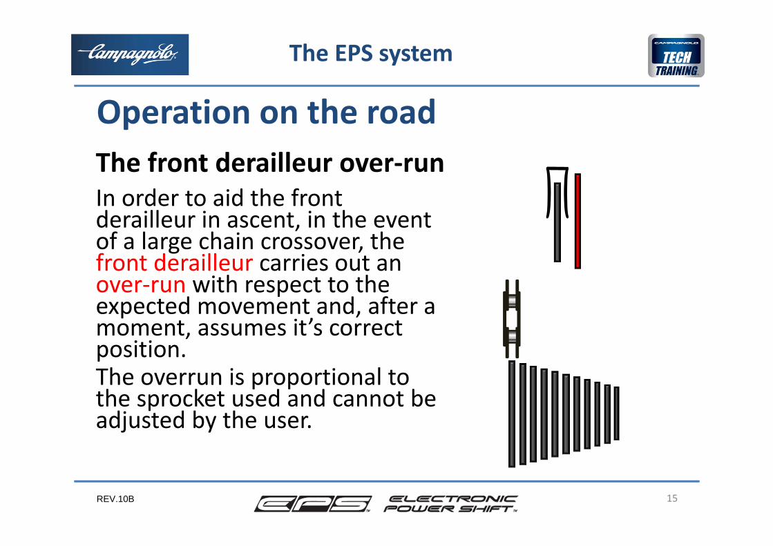
In order to aid the front derailleur in ascent, in the event of a large chain crossover, the front derailleur carries out anover‐run with respect to the expected movement and, after a moment, assumes it’s correct position. The overrun is proportional to the sprocket used and cannot be adjusted by the user.
15
The EPS system
Operation on the road The front derailleur over‐run
REV.10B
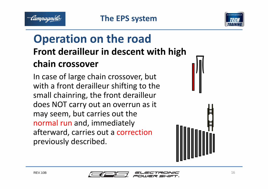
In case of large chain crossover, but with a front derailleur shifting to the small chainring, the front derailleur does NOT carry out an overrun as it may seem, but carries out the normal run and, immediately afterward, carries out a correctionpreviously described.
16
The EPS system
Operation on the road Front derailleur in descent with high chain crossover
REV.10B
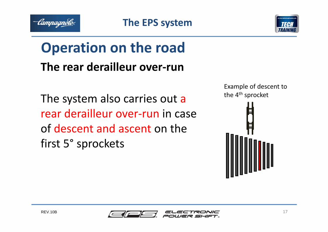
The system also carries out a rear derailleur over‐run in case of descent and ascent on the first 5° sprockets
17
The EPS system
Operation on the road
Example of descent to the 4th sprocket
The rear derailleur over‐run
REV.10B
Other advantages of the EPS system are:greater positioning precision (max error of 0.05 mm thanks to the electric motor’s position resolver) compared to a mechanical rear derailleur ‐ in whichprecision is tied to the cable movement and the returnspring in the derailleur.constant front and rear derailleur action speed, by eliminating cable frictionsoft action and limited run of the leverspossibility of braking and changing gearssimultaneouslythe design of the frame is no longer dictated by the need for simple cable runs
18
The EPS system
Operation on the road
REV.10B
The EPS system, unlike traditional systems, is made up of 6 main components, 2 of which are completely new:
right rear derailleur controlleft front derailleur controlinterfacepower unitfront derailleurrear derailleur
Each of these components has one or more cables for properinterconnection.
A battery charger is also provided in order to recharge the batteries as well asa magnet to switch off the system.
19
System components
The EPS system

REV.10B 20
System components
The EPS system

REV.10B 21
System components
The EPS system
REV.10B
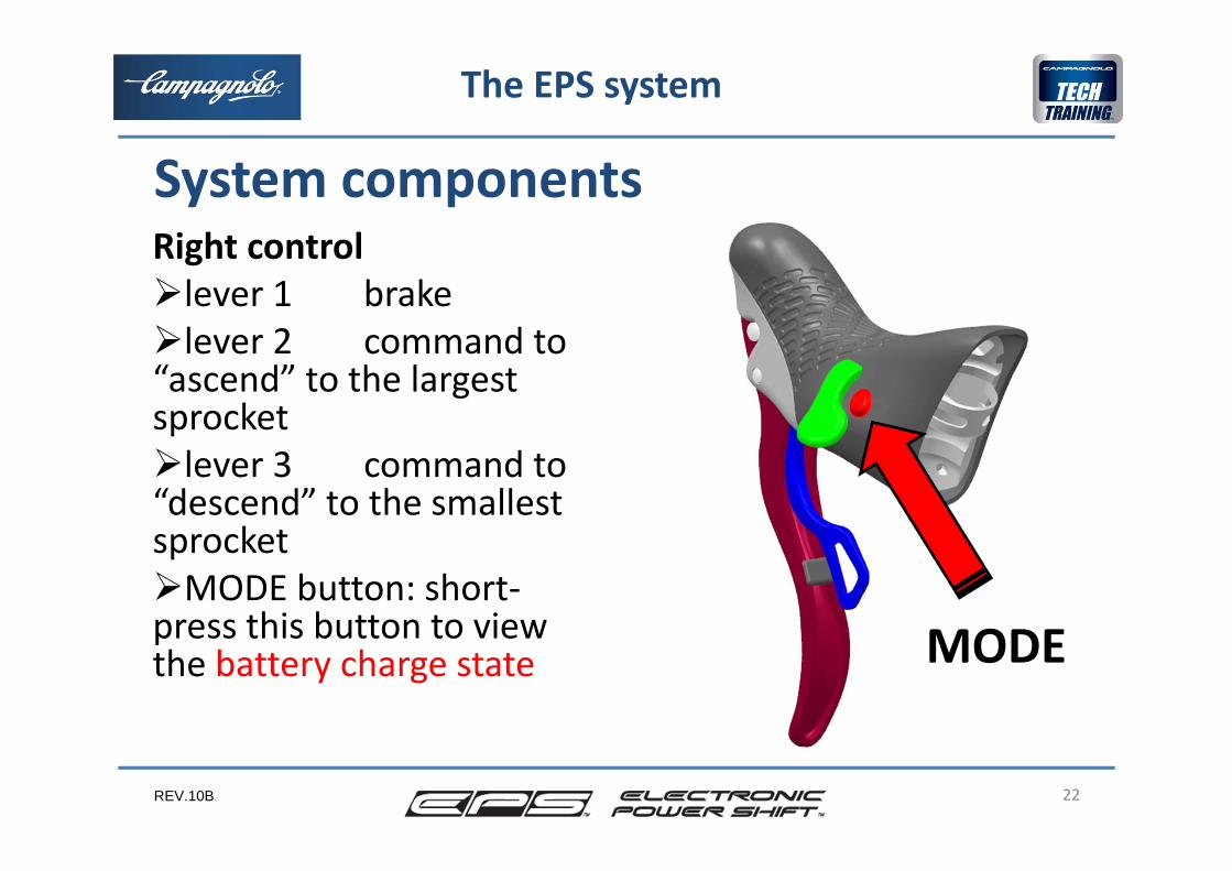
Right control lever 1 brakelever 2 command to “ascend” to the largestsprocketlever 3 command to “descend” to the smallestsprocketMODE button: short‐press this button to viewthe battery charge state
22
System components
The EPS system
MODE
REV.10B
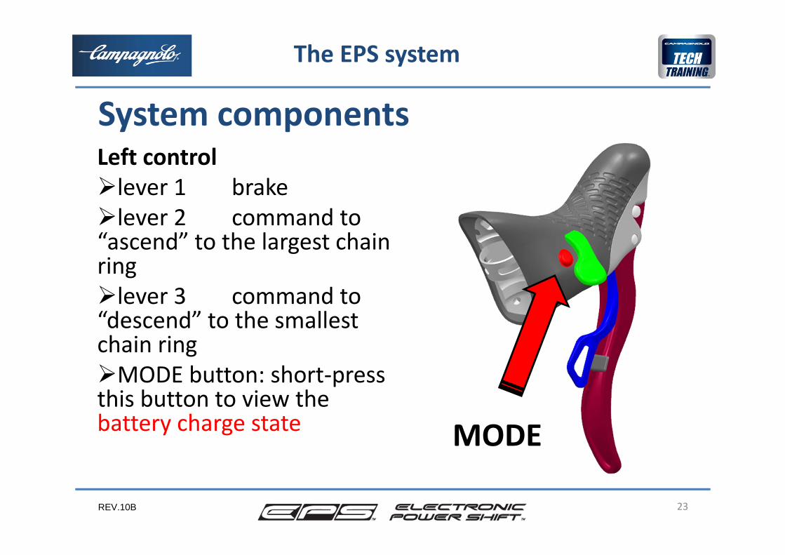
Left controllever 1 brakelever 2 command to “ascend” to the largest chainringlever 3 command to “descend” to the smallestchain ringMODE button: short‐press this button to view the battery charge state
23
System components
The EPS system
MODE
REV.10B
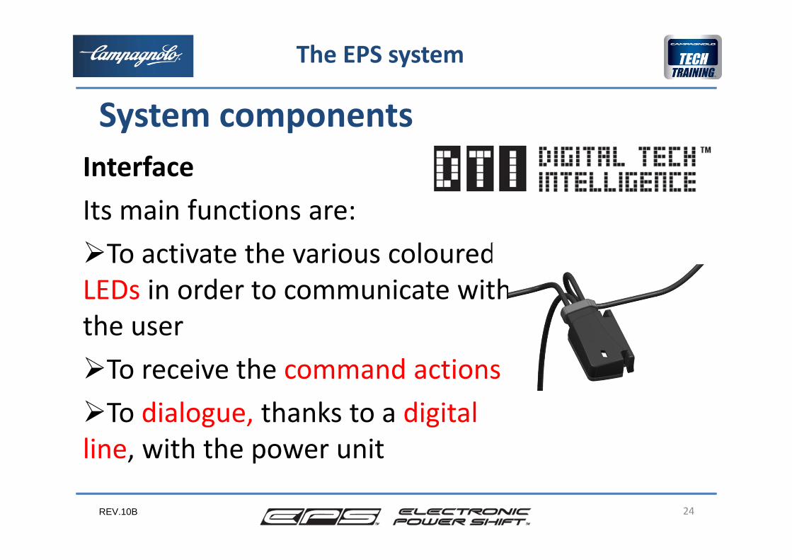
InterfaceIts main functions are:To activate the various coloured LEDs in order to communicate with the userTo receive the command actions To dialogue, thanks to a digital line, with the power unit
24
System components
The EPS system

REV.10B 25
FIXED GREEN LEDFrom 100 % to 60 % charge
FLASHING GREEN LEDFrom 60 % to 40 % charge
FIXED YELLOW LEDFrom 40 % to 20 % charge
FIXED RED LEDFrom 20 % to 6 % charge
FLASHING RED LED + ACOUSTIC ALARM (BUZZER)From 6 % to 0 % charge (using EPS every 5 min, decreasing frequencyfrom 1 to 20 min if not used since 30 min)
The battery charge level can be verified by short pressing one of the two Mode buttons
Verification of the battery charge state
The EPS system
REV.10B
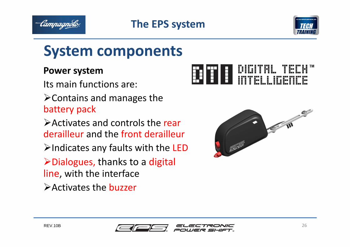
Power systemIts main functions are:Contains and manages the battery packActivates and controls the rearderailleur and the front derailleurIndicates any faults with the LEDDialogues, thanks to a digitalline, with the interfaceActivates the buzzer
26
System components
The EPS system
REV.10B
So ‐ EPS is an electronic system, controlled by a number of electronic components, that communicate and manage the drive train to obtain the best performance.
27
System components
Il sistema EPS
REV.10B 28
Il sistema EPS
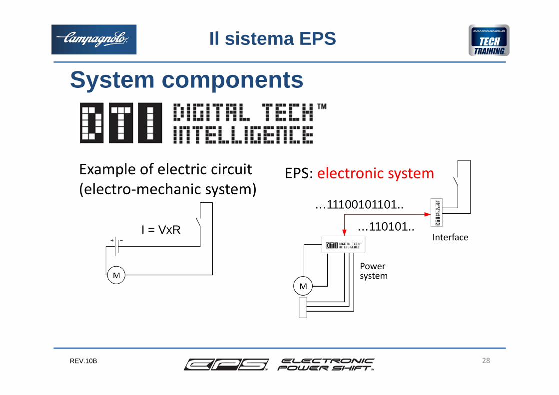
Example of electric circuit(electro‐mechanic system)
EPS: electronic system
Interface
Powersystem
I = VxR
…11100101101..
…110101..
System components

REV.10B
Average duration of the battery for use on the road: •average of 500 km/month: 1500 km•average of 1000 km/month: 1800 km•average of 2000 km/month: 2000 km
Range in km with 0‐6% charge is variable depending on the outdoor temperature and conditions of use
Battery charge times from a charge of 0‐6 % to 100%: about 4 hours.The battery has no memory effect, so you can charge it for a short time too if requested.
29
System components
The EPS system
REV.10B
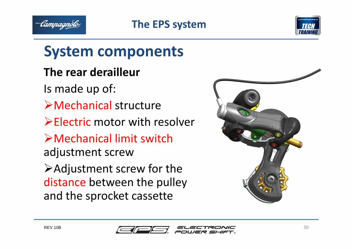
The rear derailleurIs made up of:Mechanical structureElectric motor with resolverMechanical limit switchadjustment screwAdjustment screw for the distance between the pulleyand the sprocket cassette
30
System components
The EPS system
REV.10B 31
System components
The EPS system
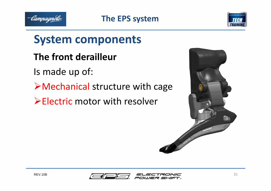
The front derailleurIs made up of:Mechanical structure with cageElectric motor with resolver
REV.10B
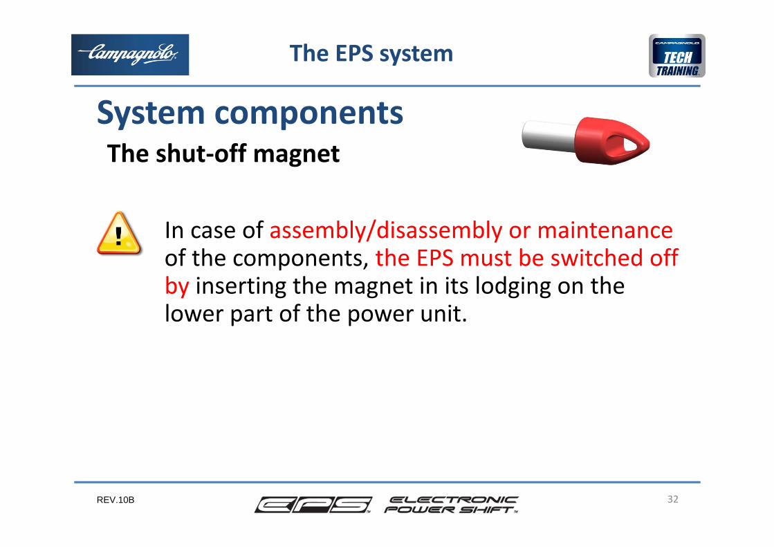
In case of assembly/disassembly or maintenanceof the components, the EPS must be switched off by inserting the magnet in its lodging on the lower part of the power unit.
32
System components
The EPS system
The shut‐off magnet
REV.10B
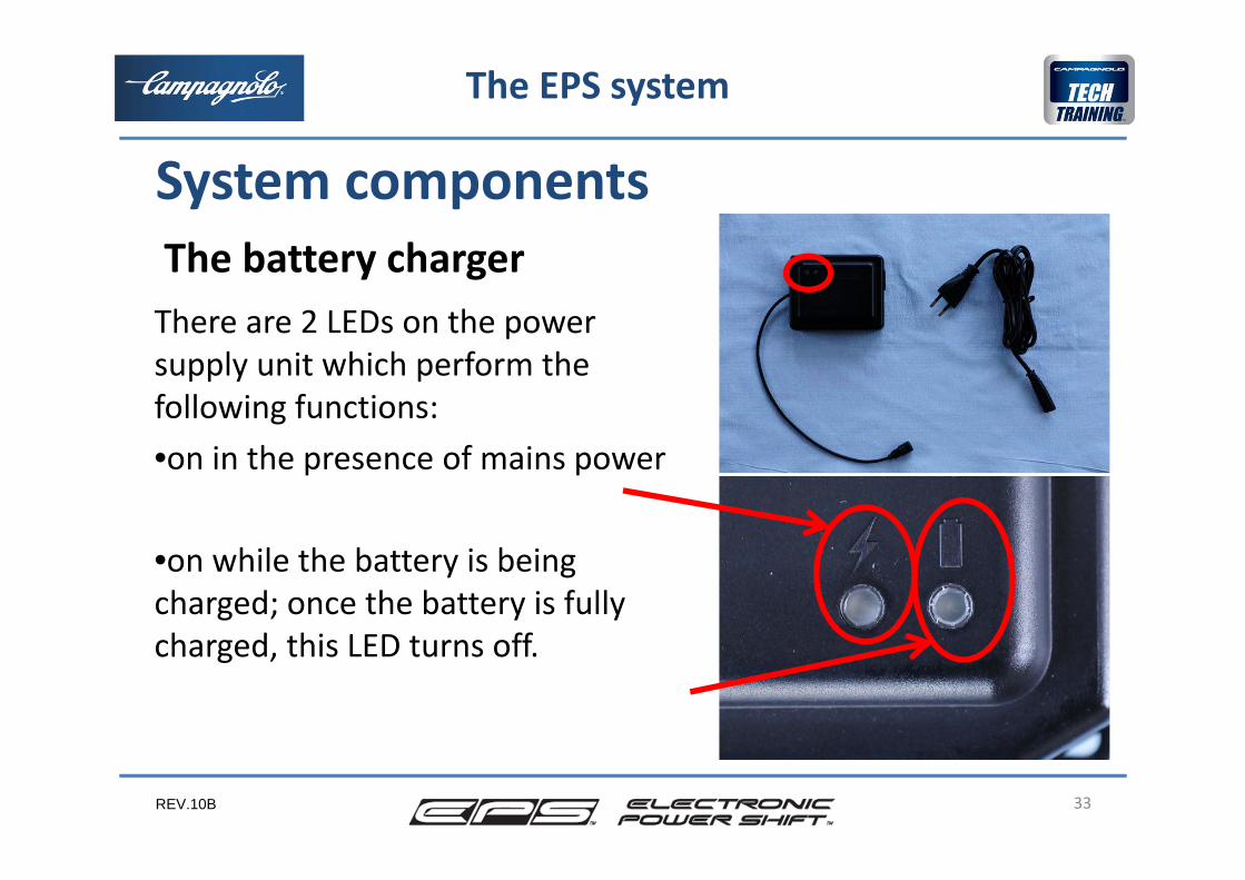
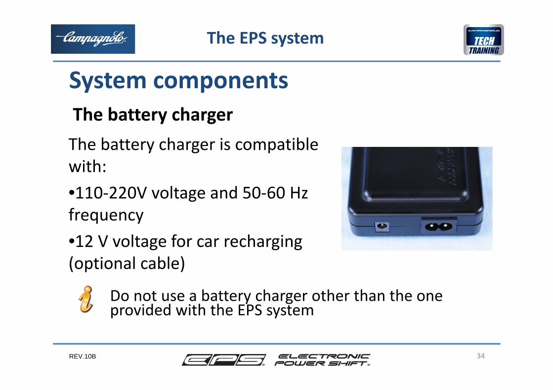
There are 2 LEDs on the power supply unit which perform the following functions:•on in the presence of mains power
•on while the battery is being charged; once the battery is fully charged, this LED turns off.
33
System components
The EPS system
The battery charger
REV.10B
The battery charger is compatible with:•110‐220V voltage and 50‐60 Hz frequency•12 V voltage for car recharging (optional cable)
34
System components
The EPS system
Do not use a battery charger other than the oneprovided with the EPS system
The battery charger
REV.10B
The battery chargerWhile recharging the interface displays the battery charge state while the rear and front derailleur motors are deactivated. In this state, even if the magnet is inserted to switch off the system, the battery charge procedure will not be interrupted.
35
System components
The EPS system
REV.10B
The MODE buttons, besides verifying the batterycharge state, allow the user tocarry out adjustments to the rear and front derailleur which correspond to the adjustmentscarried out with the cable adjusters in traditional systemscancel any temporary malfunctions detectedby the system and indicated by the LED on the power unit (please see the Diagnostics Chapter)
36
Customer adjustments
The EPS system
REV.10B
Adjustment of the rear and front derailleursThe customer can adjust the reference position of the rearand/or front derailleur through the adjustment procedure. Adjustment of the rear derailleur is done mainly in the eventof a wheel change. This might be required if the wheel that isfitted has the casette positioned differently relative to the rear drop‐out.In the case of adjustments of the rear and front derailleur, wecan position the chain on whichever chainring we wish.With each pressing of levers 2 or 3, the system carries out a fixed movement of about 0. 25 mm if we act on the rearderailleur, and about 0.1 mm if we act on the front derailleur.7 right and 7 left fixed movements are available.
37
Customer adjustments
The EPS system
REV.10B
Adjustment of the rear and front derailleursOnce adjustment is completed, the system will implement a change to the positions established for all of the sprockets (or chainrings) with a correction equal to that reset with the adjustment.For example, if the distance of the first 3 index points from the drop‐out is: 12.40 ‐ 16.60 ‐ 20.4 mmafter a correction of about 0.25 mm with lever 3 toward the drop‐out, the new positions which the rear derailleur assumes will be about:12.15 – 16.35 – 20.15 mm …
38
The EPS system
Customer adjustments
REV.10B
Adjustment of the rear and front derailleursRemember that the chain is perfectly centred, for the sprockets from the 3rd to the 10th, with about 3 movements in descent the chain approaches the lower sprocket and with 3 movements in ascent it approaches the upper sprocket.
39
The EPS system
Customer adjustments
REV.10B
Adjustment of the rear and front derailleurs
40
The EPS system
Customer adjustments
Note that any adjustment carried out whilst in motion may cause a danger of injury to the cyclist or others: proceed with extreme caution if you decide to carry out the adjustment anyway.
REV.10B
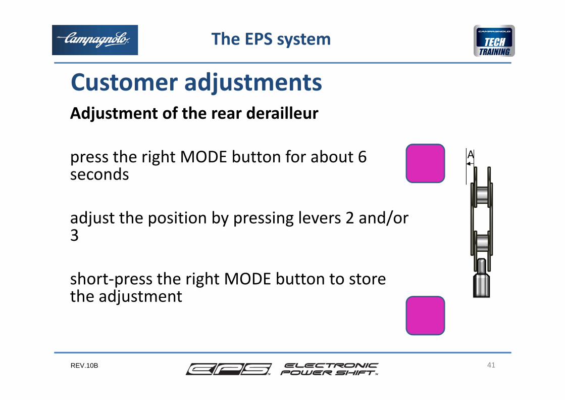
Adjustment of the rear derailleur
press the right MODE button for about 6 seconds
adjust the position by pressing levers 2 and/or 3
short‐press the right MODE button to storethe adjustment
41
A
The EPS system
Customer adjustments
REV.10B
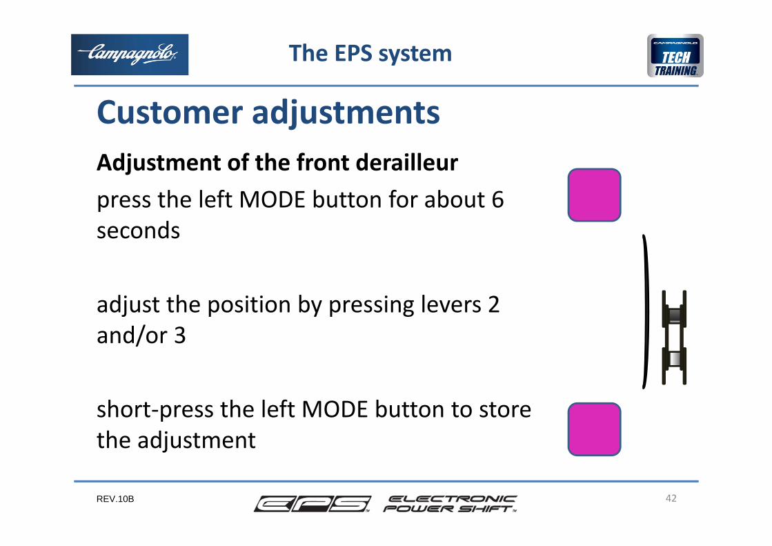
Adjustment of the front derailleurpress the left MODE button for about 6 seconds
adjust the position by pressing levers 2 and/or 3
short‐press the left MODE button to storethe adjustment
42
The EPS system
Customer adjustments
REV.10B
Failure to conclude the adjustmentIf the MODE button is not short‐pressed to conclude the adjustment procedure, after a predetermined time of about 48sec, the system automatically exits the adjustment procedure and the new adjustment is stored.
43
The EPS system
Customer adjustments
Contemporary adjustment of front and rear derailleurWhen you press one of the two MODE button, right or left, it’spossible to do the adjustment of the front or rear derailleur.The memorization can be done with one of the 2 MODE buttons.
REV.10B 44
2
1
4
3
5
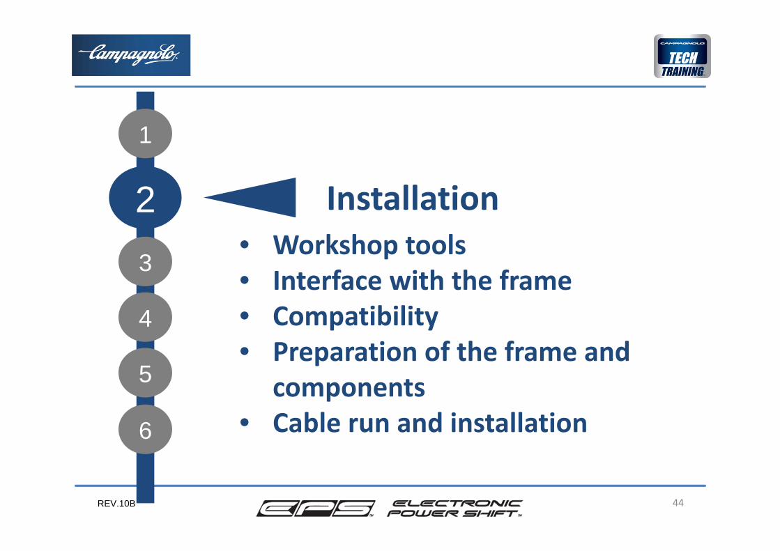
Installation • Workshop tools• Interface with the frame• Compatibility• Preparation of the frame and
components• Cable run and installation6
REV.10B
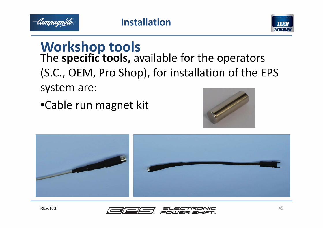
The specific tools, available for the operators(S.C., OEM, Pro Shop), for installation of the EPS system are:•Cable run magnet kit
45
Installation
Workshop tools
REV.10B
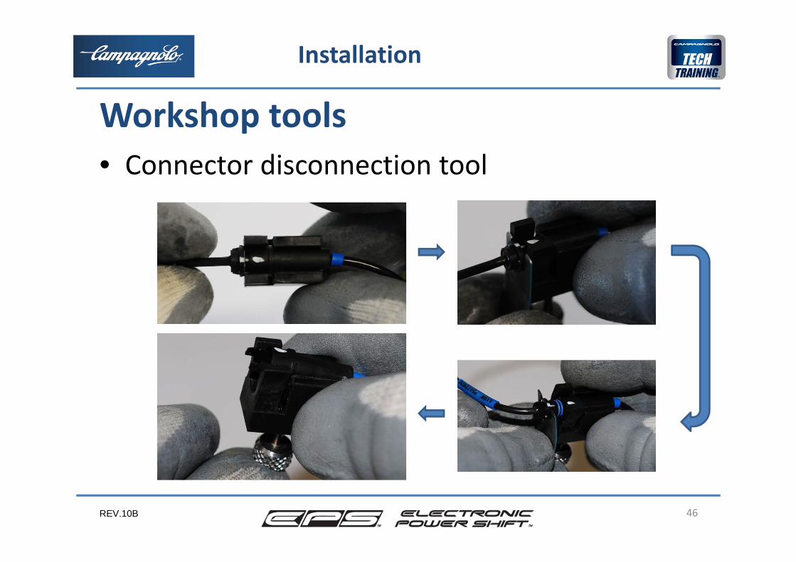
• Connector disconnection tool
46
Installation
Workshop tools

REV.10B
The generic tools for the EPS system are:
47
Installation
Workshop tools
Tool code or size used forChain tool UT‐CN300 chainTorque wrench 20‐100 Nm BB axle, BB cupsBB cups tool (for torque wrench) UT‐BB130 BB cupsAllen wrench UT‐BB110 BB Torque wrench 0 ‐ 20 Nm ergopower, rear gear, f. deraill.clamp on Allen wrench (for torque wrench) 5 ergopower, rear gear, f. deraill.clamp on Torx wrench (for torque wrench) T25 rear deraillerCaliper frameAllen wrench 2‐3‐4‐5‐6 variousTorx wrench T25 rear deraillerPhilips screwdriver 1,5 ergopower coverPhilips screwdriver mediumScrewdriver mediumWrench 7 front deraillerCutter housingPliers flat tips variousDerailleur Hanger Alignment Gauge to check the drop outBottom Bracket Tapping & Facing Set frameThickness gauge chain position
REV.10B
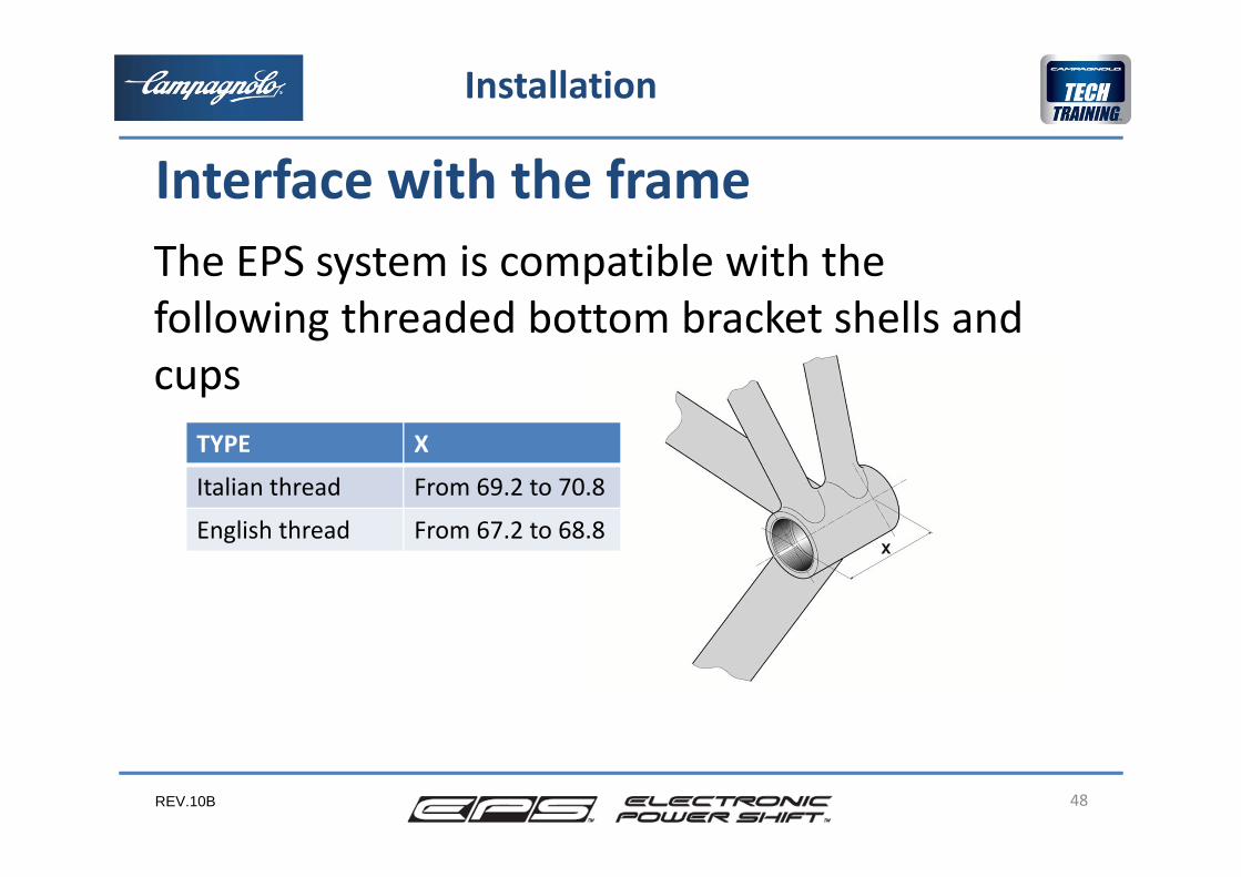
The EPS system is compatible with the following threaded bottom bracket shells and cups
48
Installation
Interface with the frame
TYPE X
Italian thread From 69.2 to 70.8
English thread From 67.2 to 68.8
REV.10B
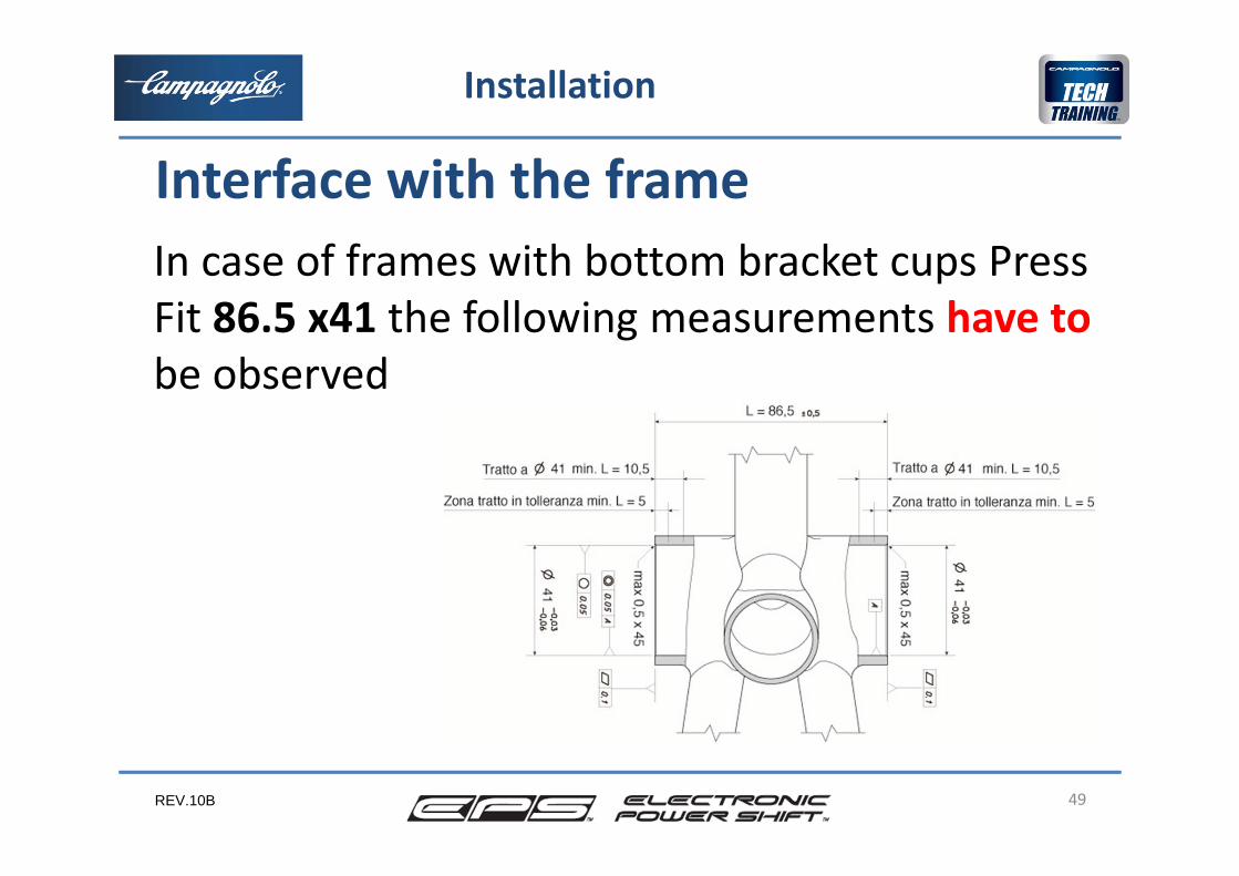
In case of frames with bottom bracket cups Press Fit 86.5 x41 the following measurements have to be observed
49
Installation
Interface with the frame
REV.10B
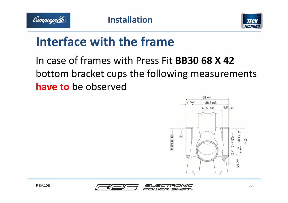
In case of frames with Press Fit BB30 68 X 42bottom bracket cups the following measurements have to be observed
50
Installation
Interface with the frame
REV.10B 51
Installation
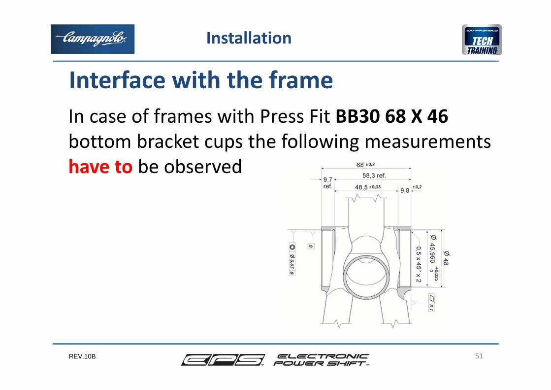
In case of frames with Press Fit BB30 68 X 46bottom bracket cups the following measurements have to be observed
Interface with the frame
REV.10B 52
Installation
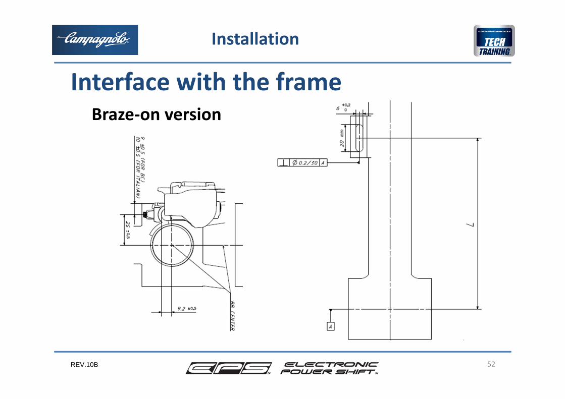
Braze‐on version
Interface with the frame
REV.10B 53
Installation
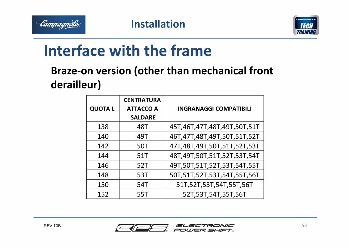
QUOTA L CENTRATURA ATTACCO A SALDARE
INGRANAGGI COMPATIBILI
138 48T 45T,46T,47T,48T,49T,50T,51T 140 49T 46T,47T,48T,49T,50T,51T,52T 142 50T 47T,48T,49T,50T,51T,52T,53T 144 51T 48T,49T,50T,51T,52T,53T,54T 146 52T 49T,50T,51T,52T,53T,54T,55T 148 53T 50T,51T,52T,53T,54T,55T,56T 150 54T 51T,52T,53T,54T,55T,56T 152 55T 52T,53T,54T,55T,56T
Braze‐on version (other than mechanical front derailleur)
Interface with the frame
REV.10B 54
Installation
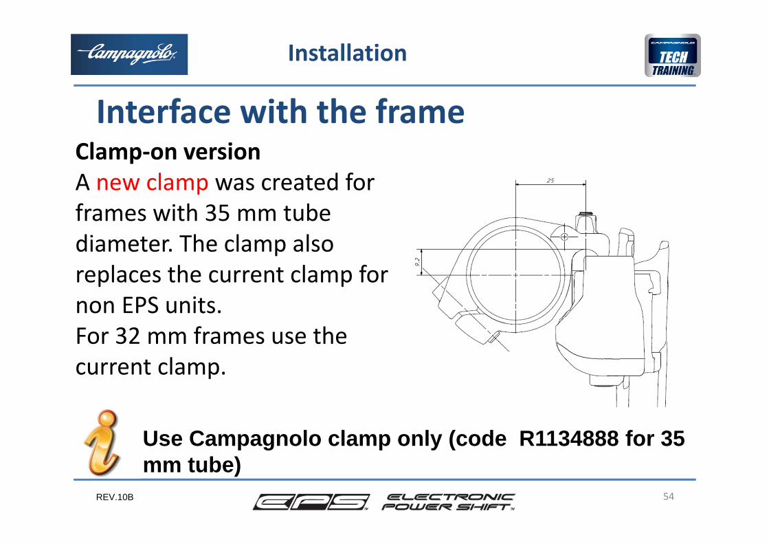
Clamp‐on versionA new clamp was created for frames with 35 mm tube diameter. The clamp also replaces the current clamp for non EPS units.For 32 mm frames use the current clamp.
Interface with the frame
Use Campagnolo clamp only (code R1134888 for 35 mm tube)
REV.10B 55
Installation
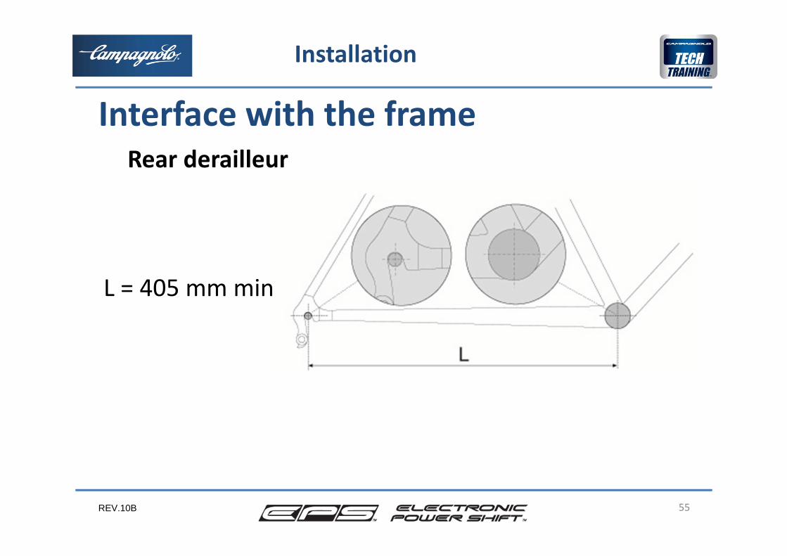
Rear derailleur
L = 405 mm min
Interface with the frame
REV.10B 56
Installation
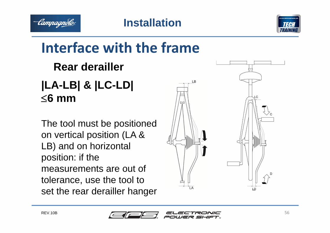
Rear derailler|LA-LB| & |LC-LD|6 mm
The tool must be positioned on vertical position (LA & LB) and on horizontal position: if the measurements are out of tolerance, use the tool to set the rear derailler hanger
Interface with the frame
REV.10B 57
Installation
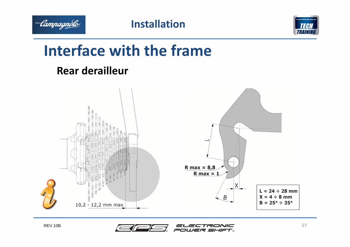
Rear derailleur
Interface with the frame
REV.10B 58
Installation
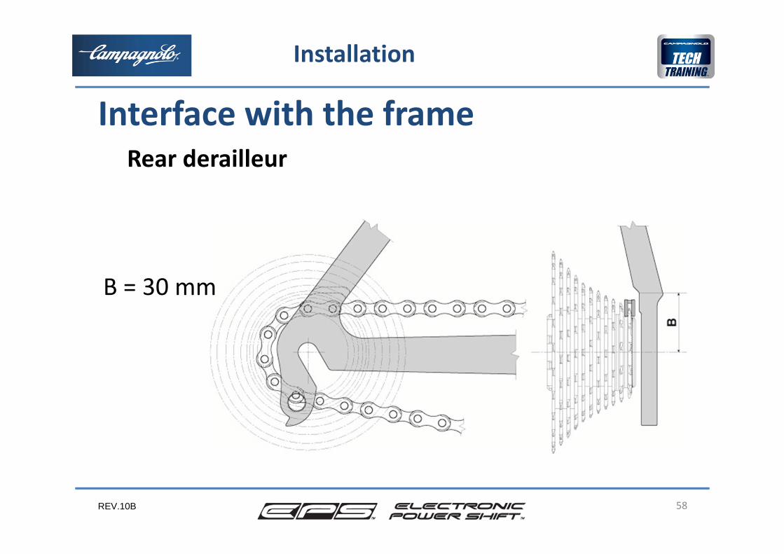
Rear derailleur
B = 30 mm
Interface with the frame
REV.10B
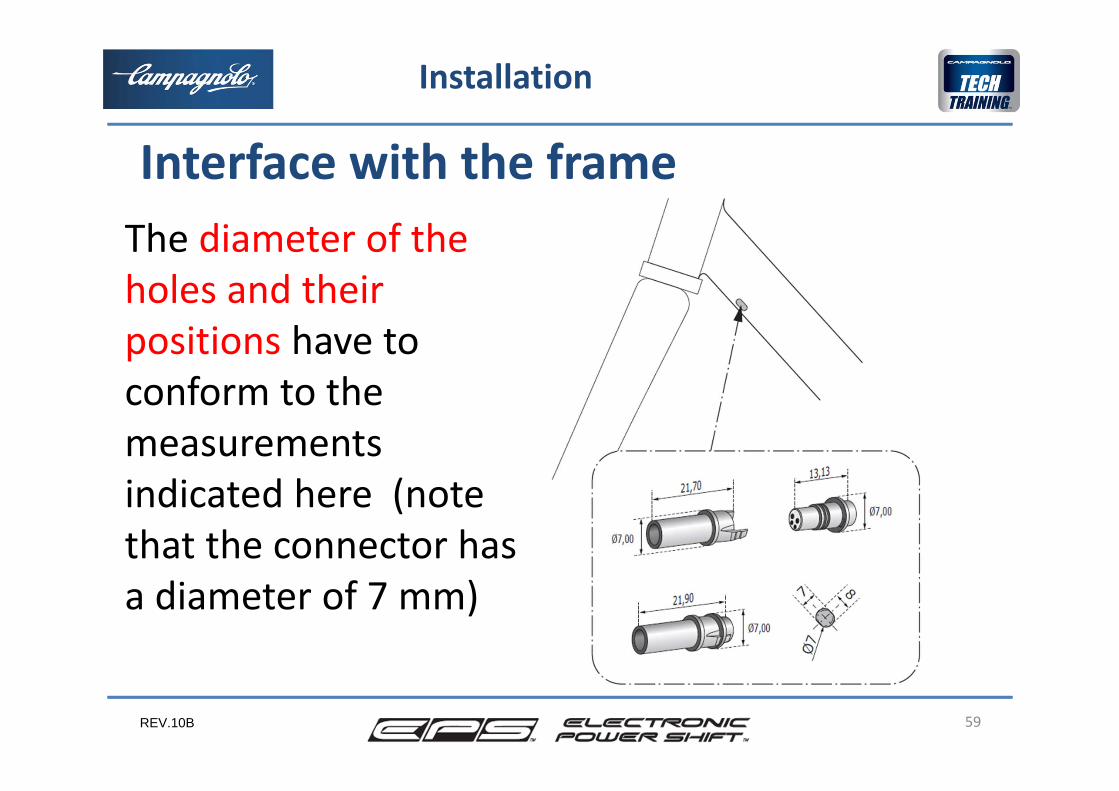
The diameter of the holes and their positions have to conform to the measurements indicated here (note that the connector has a diameter of 7 mm)
59
Installation
Interface with the frame
REV.10B 60
Installation
Interface with the frame
REV.10B 61
Installation
Interface with the frame
M4
M5
M2,5
REV.10B 62
Installation
Interface with the frame
REV.10B
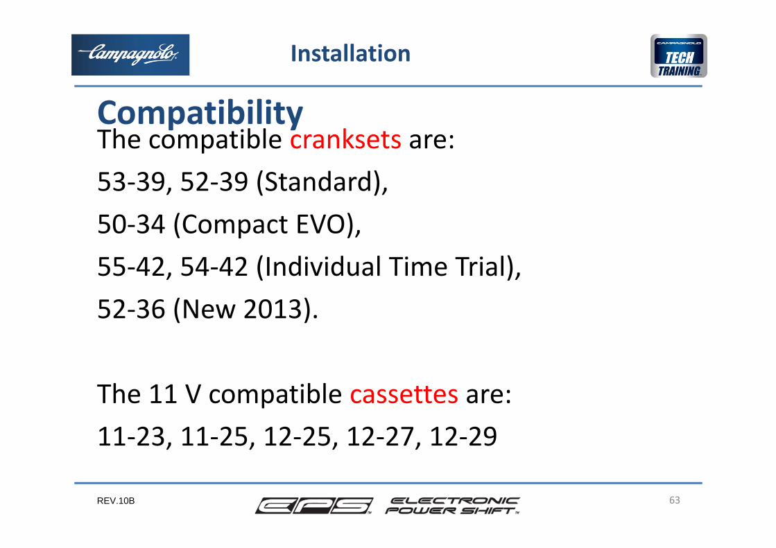
The compatible cranksets are: 53‐39, 52‐39 (Standard),50‐34 (Compact EVO), 55‐42, 54‐42 (Individual Time Trial), 52‐36 (New 2013).
The 11 V compatible cassettes are:11‐23, 11‐25, 12‐25, 12‐27, 12‐29
63
Installation
Compatibility
REV.10B
For complete functionality of the EPS system the dimensions of the compatible chainrings or sprockets cannot be changed.
64
Installation
Compatibility

REV.10B 65
Installation
Preparation of the frame and components Because the presence of impurities, dirt or even worse, liquids, must be avoided during assembly of the electrical connectors, it is important that installation of the EPS system is carried out with clean hands, in a clean environment and not carried out whilst exposed to inclement weather in order to avoid the presence of dust, grease, water, etc. during installation.
REV.10B
Before installation, where possible, remember to millthe bottom bracket shell with the bottom braket facingtool in order to have:
•the two surfaces faced•the correct chain line: 43,5 mm
66
Installation
Preparation of the frame and components
REV.10B
It’s important to chase the thread of the rear derailler hanger to install correctly the rear derailler.
Verify that the frame is free of any possible obstructions internally (i.e. bags from the production of carbon frames ...)
67
Installation
Preparation of the frame and components
REV.10B
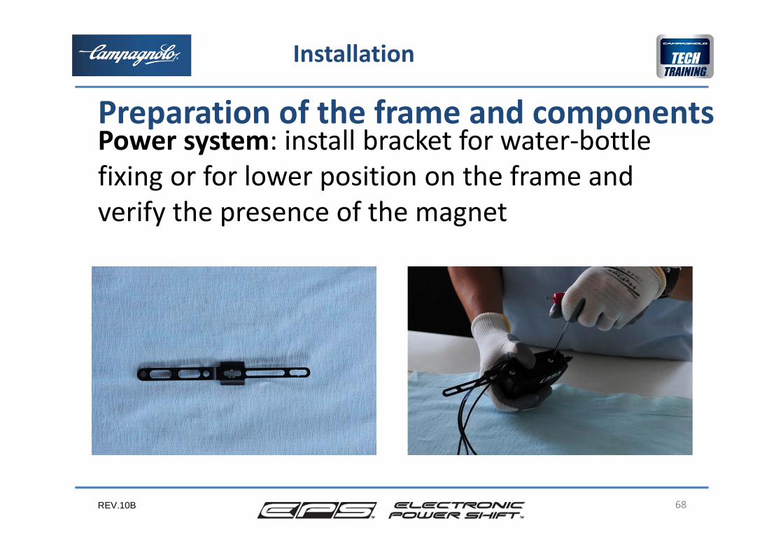
Power system: install bracket for water‐bottle fixing or for lower position on the frame and verify the presence of the magnet
68
Installation
Preparation of the frame and components
REV.10B 69
Installation
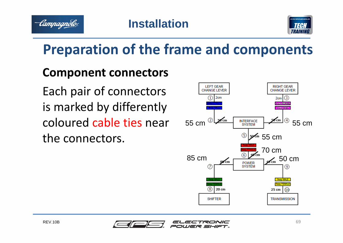
70 cm
55 cm 55 cm
55 cm
50 cm85 cm
Component connectorsEach pair of connectors is marked by differently coloured cable ties near the connectors.
Preparation of the frame and components
REV.10B
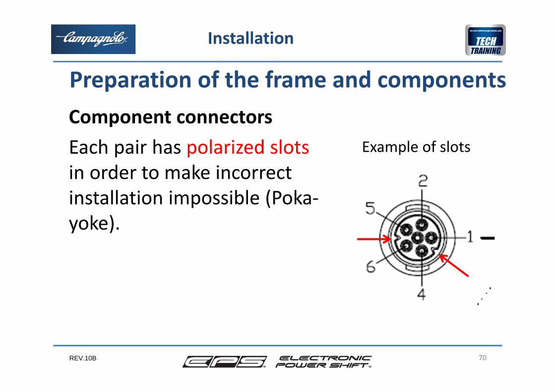
Component connectorsEach pair has polarized slots in order to make incorrect installation impossible (Poka‐yoke).
70
Installation
Preparation of the frame and components
Example of slots
REV.10B
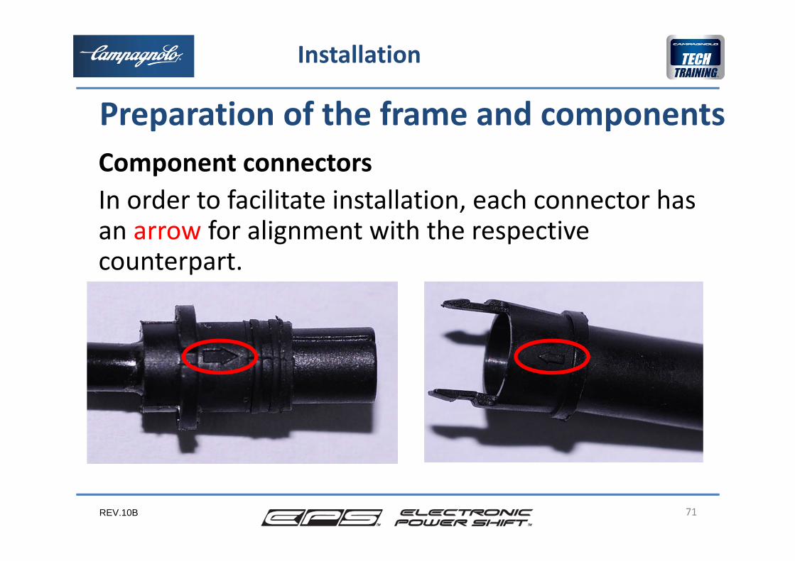
Component connectorsIn order to facilitate installation, each connector has an arrow for alignment with the respective counterpart.
71
Installation
Preparation of the frame and components
REV.10B 72
Installation
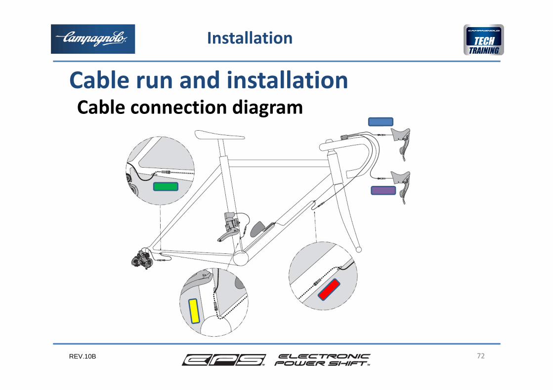
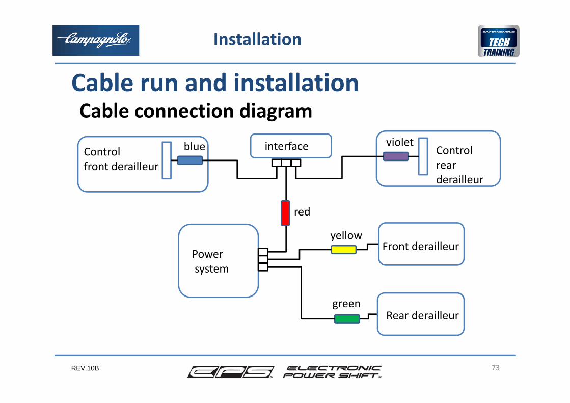
Cable run and installationCable connection diagram
REV.10B 73
Installation
Cable run and installation
Control front derailleur
interface
Powersystem
Front derailleur
Rear derailleur
Control rear derailleur
yellow
green
red
blue violet
Cable connection diagram
REV.10B 74
Installation
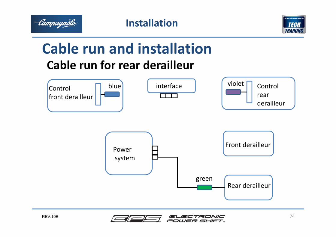
Control front derailleur
interface
Powersystem
Front derailleur
Rear derailleur
Control rear derailleur
green
blue violet
Cable run and installationCable run for rear derailleur
REV.10B
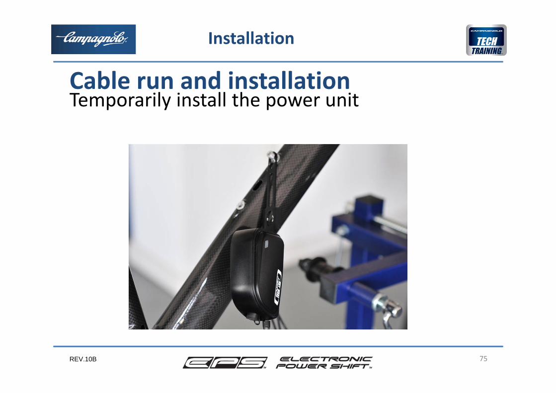
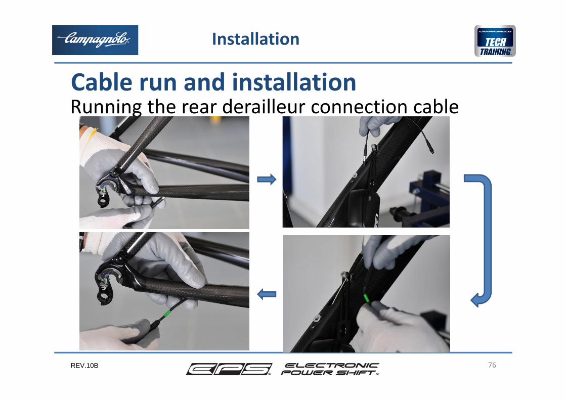
Temporarily install the power unit
75
Installation
Cable run and installation
REV.10B
Running the rear derailleur connection cable
76
Installation
Cable run and installation
REV.10B 77
Installation
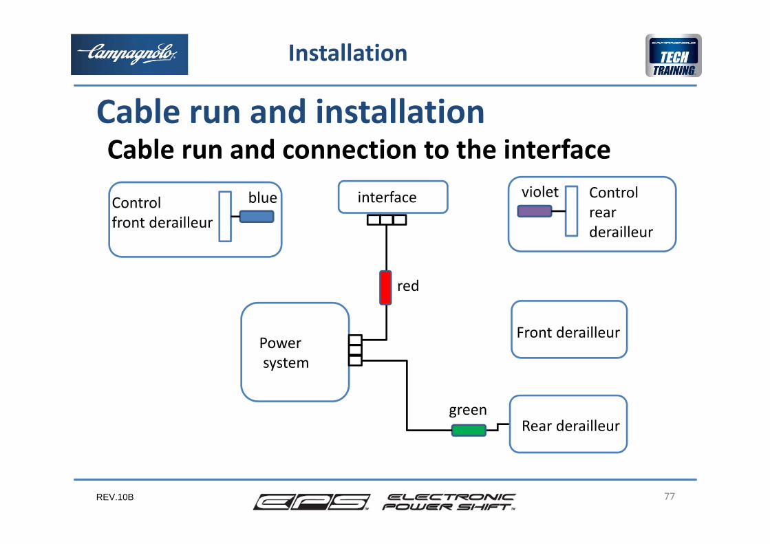
Control front derailleur
interface
Powersystem
Front derailleur
Rear derailleur
Control rear derailleur
green
red
blue violet
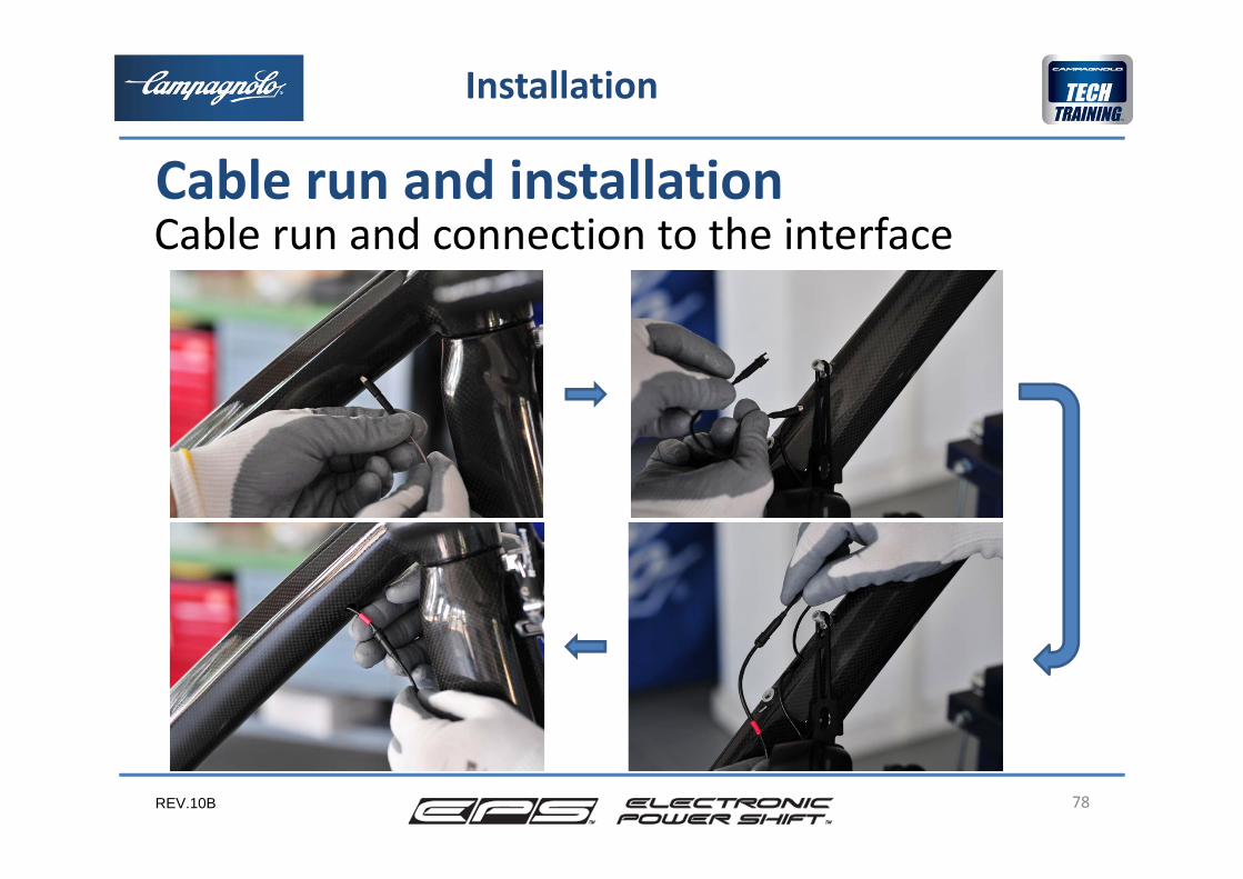
Cable run and connection to the interface Cable run and installation
REV.10B
Cable run and connection to the interface
78
Installation
Cable run and installation
REV.10B 79
Installation
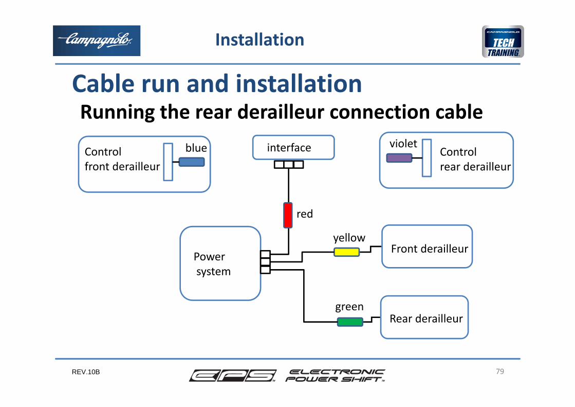
Controlfront derailleur
interface
Powersystem
Front derailleur
Rear derailleur
Control rear derailleur
yellow
green
red
blue violet
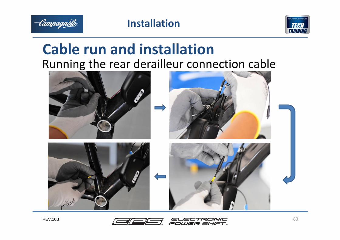
Running the rear derailleur connection cable Cable run and installation
REV.10B
Running the rear derailleur connection cable
80
Installation
Cable run and installation
REV.10B
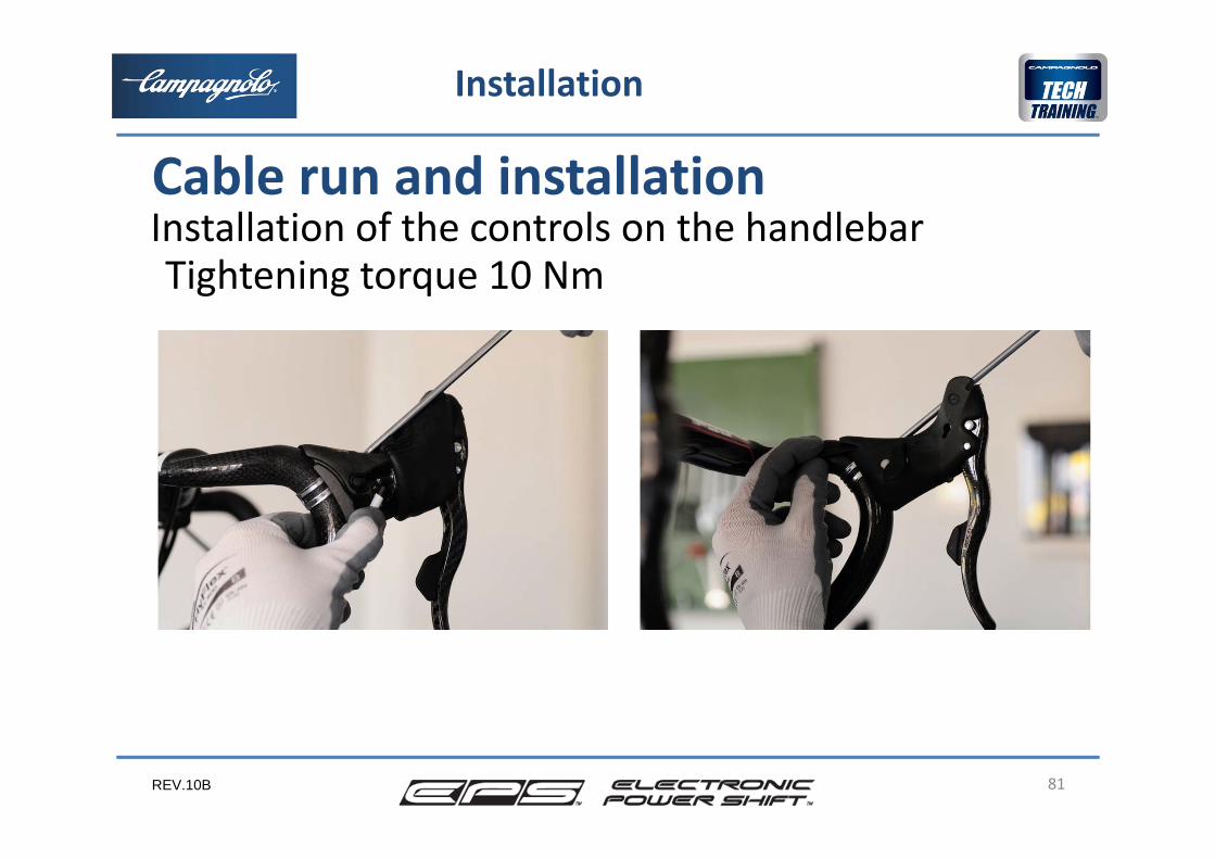
Installation of the controls on the handlebar
81
Installation
Cable run and installation
Tightening torque 10 Nm
REV.10B
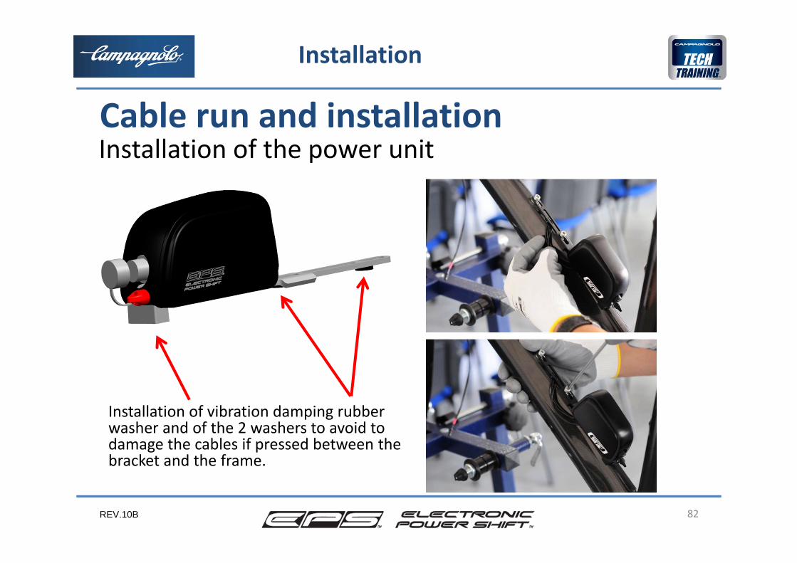
Installation of the power unit
82
Installation
Cable run and installation
Installation of vibration damping rubberwasher and of the 2 washers to avoid to damage the cables if pressed between the bracket and the frame.
REV.10B
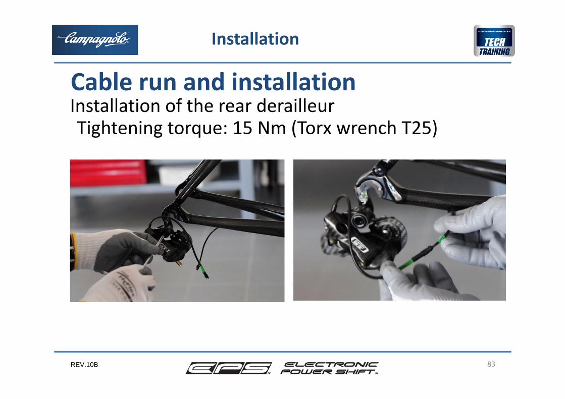
Installation of the rear derailleur
83
Installation
Cable run and installation
Tightening torque: 15 Nm (Torx wrench T25)
REV.10B
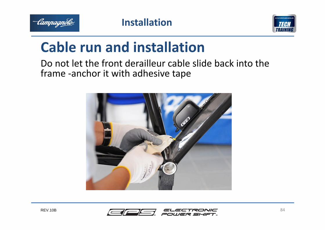
Do not let the front derailleur cable slide back into the frame ‐anchor it with adhesive tape
84
Installation
Cable run and installation
REV.10B
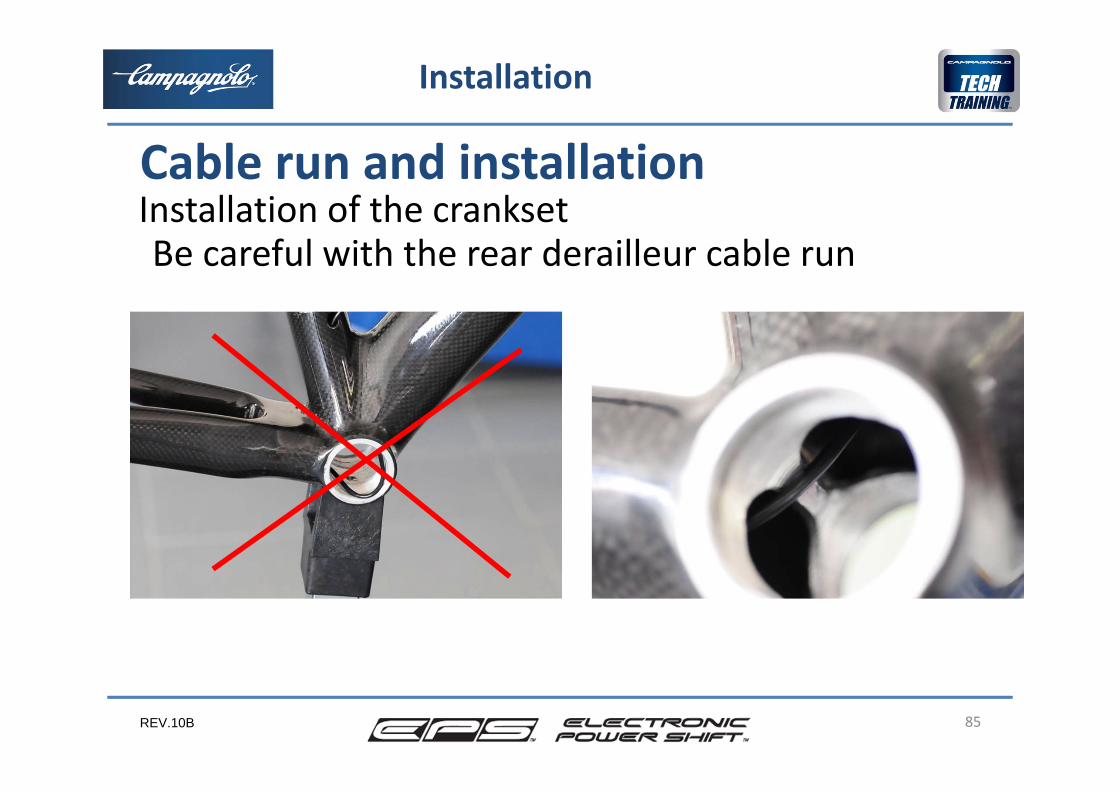
Installation of the crankset
85
Installation
Cable run and installation
Be careful with the rear derailleur cable run
REV.10B 86
I ricambi e la garanzia
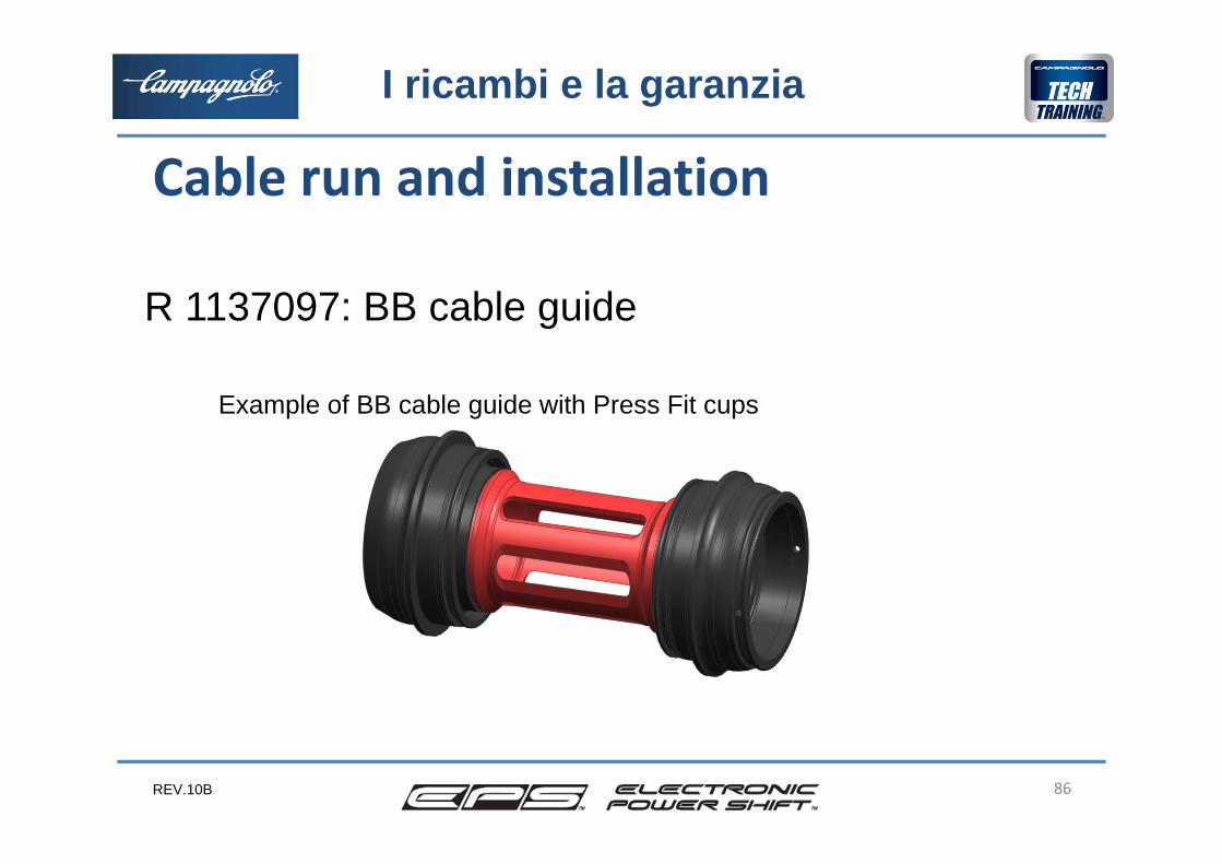
R 1137097: BB cable guide
Example of BB cable guide with Press Fit cups
Cable run and installation
REV.10B
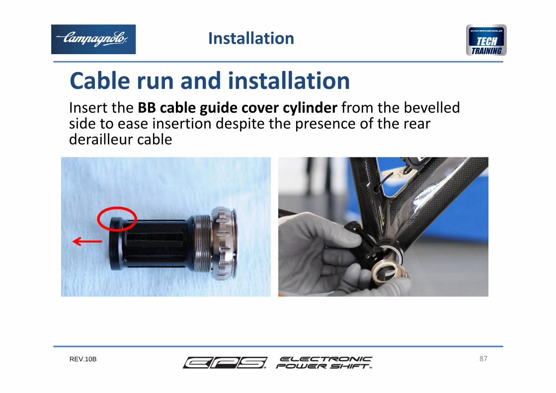
Insert the BB cable guide cover cylinder from the bevelled side to ease insertion despite the presence of the rear derailleur cable
87
Installation
Cable run and installation

REV.10B 88
Installation
Cable run and installationInstallation of the cranksetBottom bracket cup tightening torque 35 Nm with tool UT‐BB130Crankset tightening torque: 42‐60 Nm
REV.10B 89
Installation
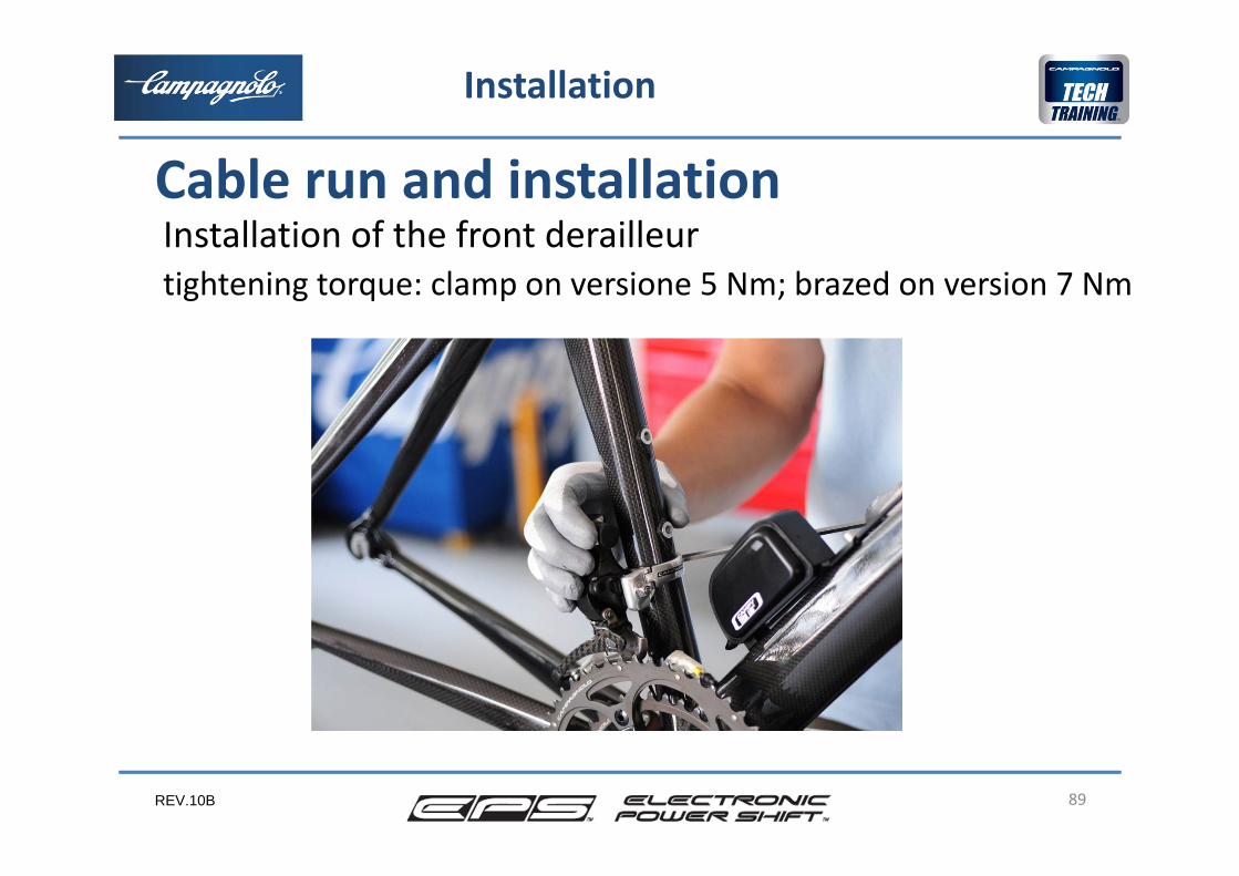
Cable run and installationInstallation of the front derailleurtightening torque: clamp on versione 5 Nm; brazed on version 7 Nm
REV.10B 90
Installation
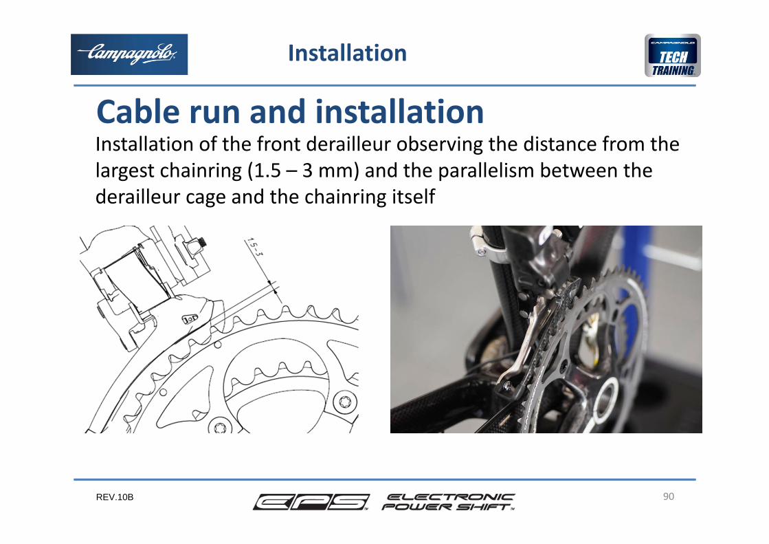
Cable run and installationInstallation of the front derailleur observing the distance from the largest chainring (1.5 – 3 mm) and the parallelism between the derailleur cage and the chainring itself
REV.10B 91
Installation
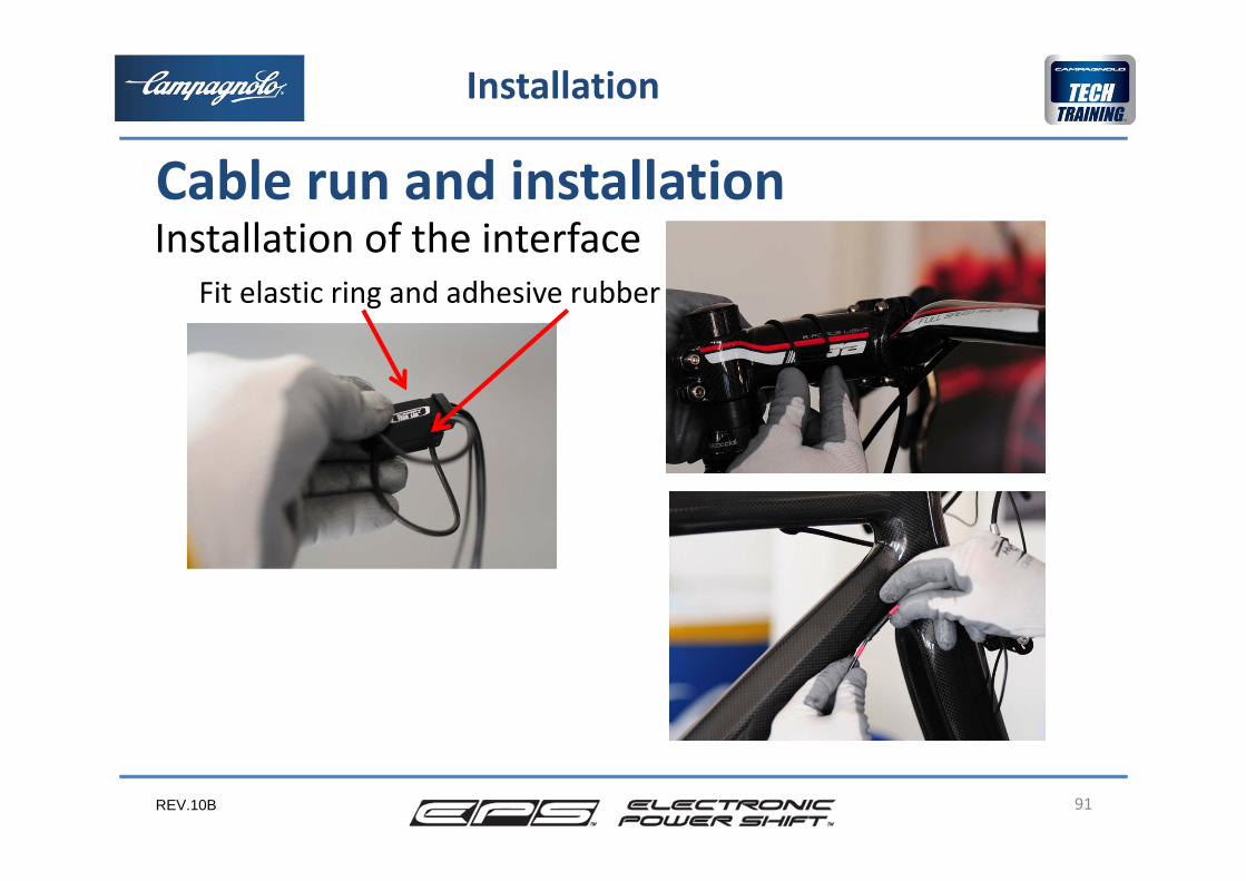
Cable run and installationInstallation of the interface
Fit elastic ring and adhesive rubber
REV.10B 92
Installation
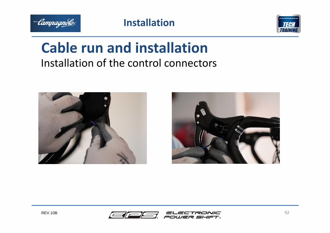
Cable run and installationInstallation of the control connectors
REV.10B 93
Installation
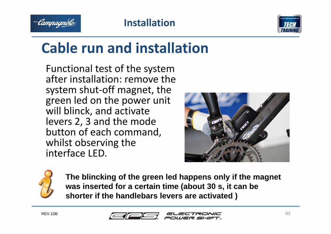
Cable run and installationFunctional test of the systemafter installation: remove the system shut‐off magnet, the green led on the power unitwill blinck, and activatelevers 2, 3 and the mode button of each command, whilst observing the interface LED.
The blincking of the green led happens only if the magnet was inserted for a certain time (about 30 s, it can be shorter if the handlebars levers are activated )
REV.10B 94
Installation
Cable run and installationThe final phases of installation are:•completion of installation of the controls•power unit cable protection•installation of rubber grommets•chain installation
REV.10B
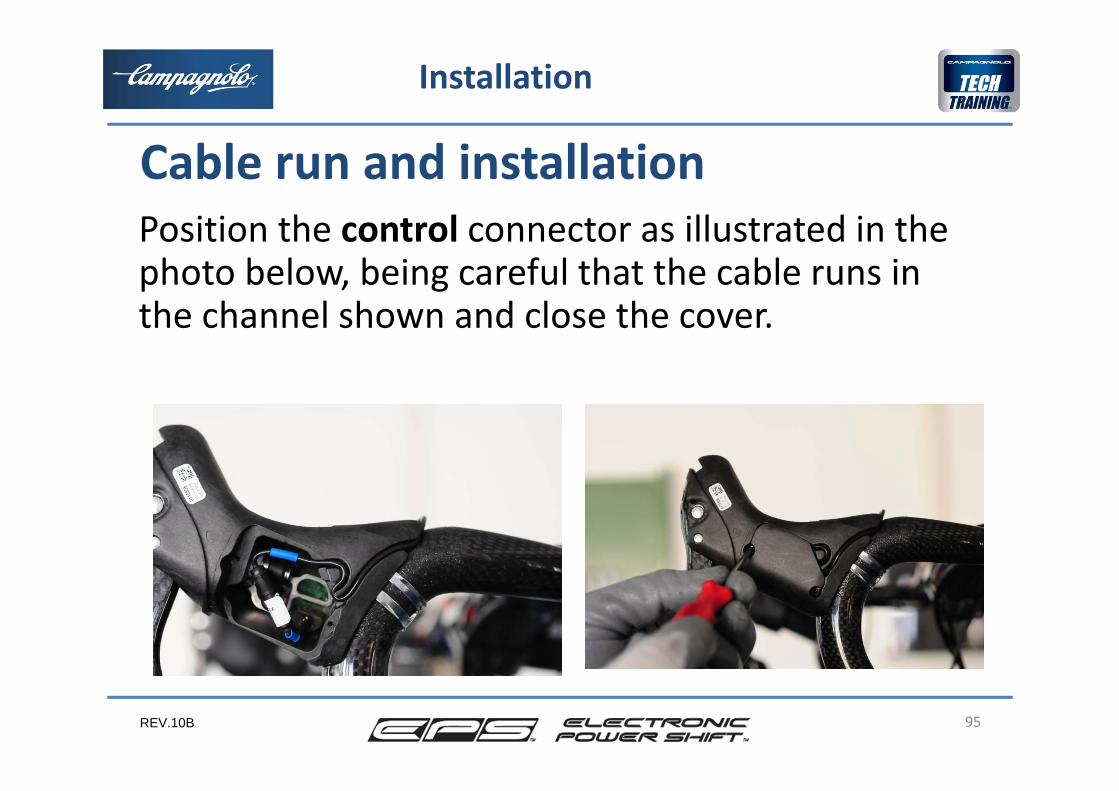
Position the control connector as illustrated in the photo below, being careful that the cable runs in the channel shown and close the cover.
95
Installation
Cable run and installation
REV.10B 96
Installation
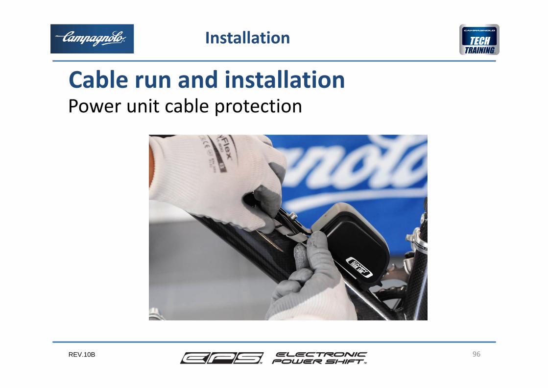
Cable run and installationPower unit cable protection
REV.10B 97
Installation
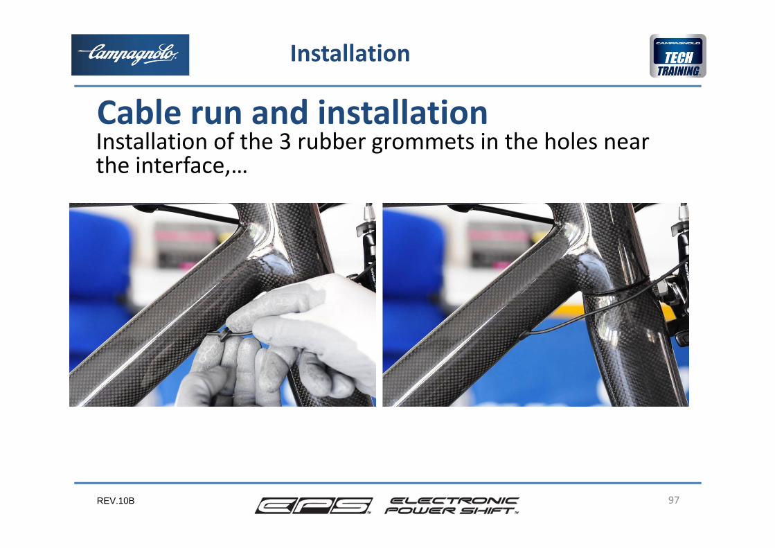
Cable run and installationInstallation of the 3 rubber grommets in the holes near the interface,…
REV.10B 98
Installation
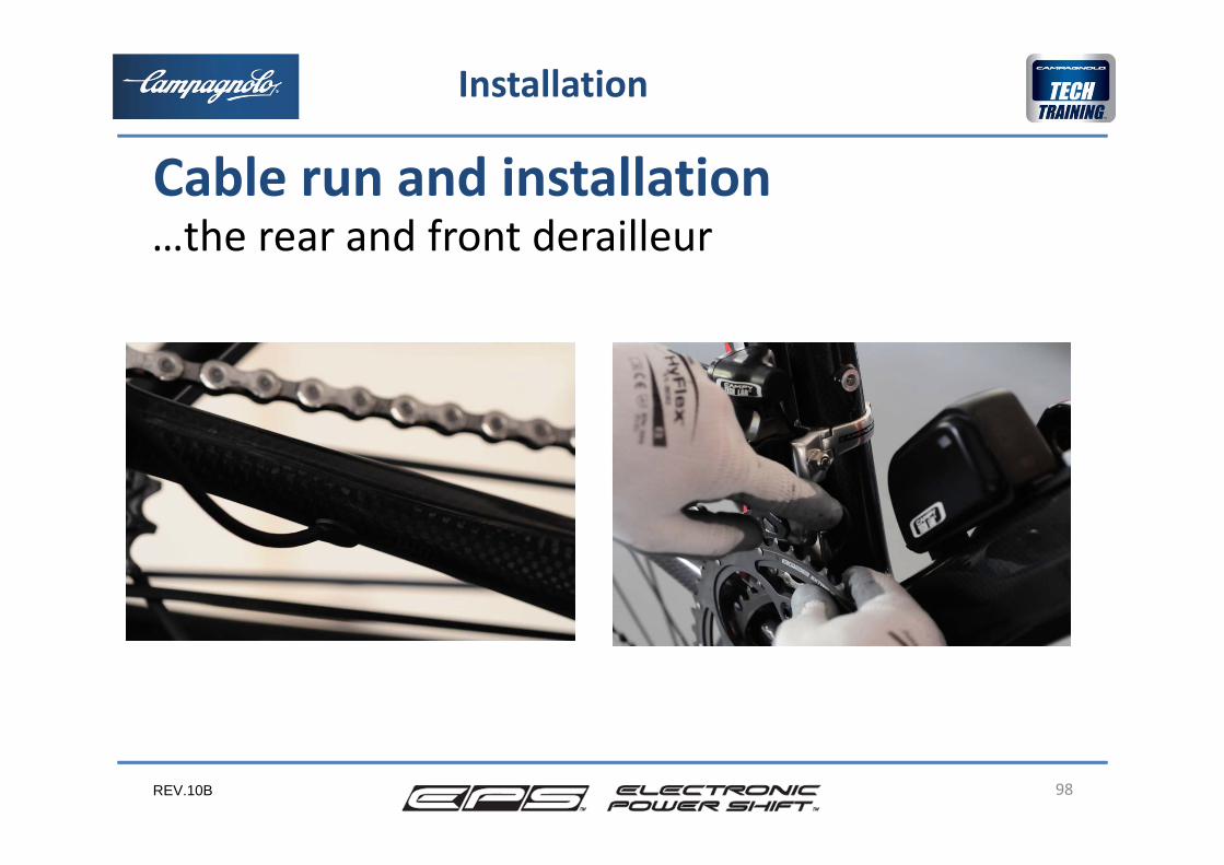
Cable run and installation…the rear and front derailleur
REV.10B 99
Installation
Cable run and installationChainInstall the chain in accordance with the procedure required for the mechanical groups using the tool UT‐CN300
REV.10B 100
Installation
Cable run and installation
After completing the installation of the EPS group, we are now ready to carry out the adjustments.
REV.10B 101
3
2
4
5
Adjustments after installation
1
6
• The phases• The rear derailleur reset procedure• The rear derailleur mechanical
travel limit• Jockey cage distance adjustment• The front derailleur reset procedure• Conclusion
REV.10B
The EPS system, after installation, needs to know the position of 2 sprockets and of one chainring, in order to calculate the position of all the other sprockets and of the other chainring.
Additionally it’s necessary to make a mechanical setting of the rear derailleur for a perfect functionality and to avoid any possibility that the rear derailleur might touch the spokes.
In the following page are the phases of the adjustment after the installation.
102
The phases
Adjustment after installation
REV.10B
A. Rear derailleur resetB. Rear derailleur travel limit adjustmentC. Jockey cage distance adjustmentD. Front derailleur resetE. Test on the road of the EPS system with evaluation of
the behaviour of the transmissionF. Correction of the system behaviour with the front
and/or rear derailleur adjustment or resetting of the front and/or rear derailleur.
103
The phases
Adjustment after installation
REV.10B
The rear and front derailleur reset procedures are fundamentalfor proper operation of the system.These procedures allow the system to learn the reference positions of the chain on the sprockets and the chainrings from which it can then calculate the position to assume in all operating conditions.During the reset phase movements of the rear and front derailleur take place continuously, and not with fixed movements as during adjustment, depending on the time that rear derailleur levers 2 and 3 are held in. It is possible to modify the position by just a few hundredths of a millimetre.
104
The reset procedures
Adjustment after installation
REV.10B 105
Rear derailleur reset procedureThis procedure allows the system to learn the position of the 2ndand 10th sprocket with respect to the rear derailleur drop‐out attachment.Starting from these two reference positions, the system will calculate the position of all the other sprockets.In the 11 speed units the distance between the two adjacent sprockets is 3.8 mm except:•between the 1st and 2nd it is 4.3 mm for 11 t smallest sprocket and 4.2 mm for 12 t smallest sprocket•between the 2nd and 3rd it is 3.94 mm for 11 t smallest sprocket Overall tolerance for each sprocket position with respect to the first: +/‐0.1 mm.
Adjustments after installation
REV.10B
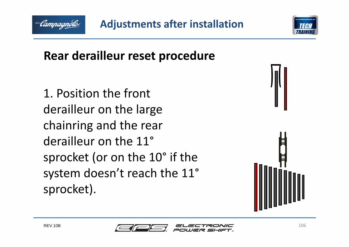
1. Position the front derailleur on the large chainring and the rear derailleur on the 11°sprocket (or on the 10° if the system doesn’t reach the 11°sprocket).
106
Rear derailleur reset procedure
Adjustments after installation
REV.10B
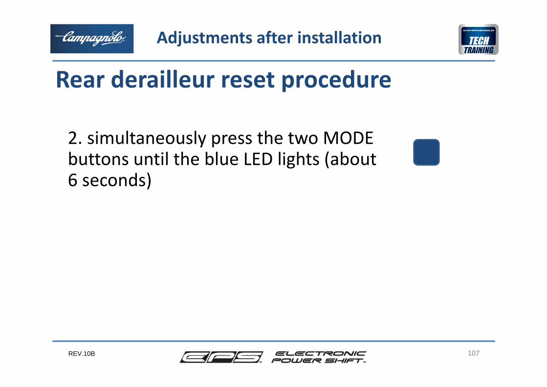
2. simultaneously press the two MODE buttons until the blue LED lights (about6 seconds)
107
Rear derailleur reset procedure
Adjustments after installation
REV.10B
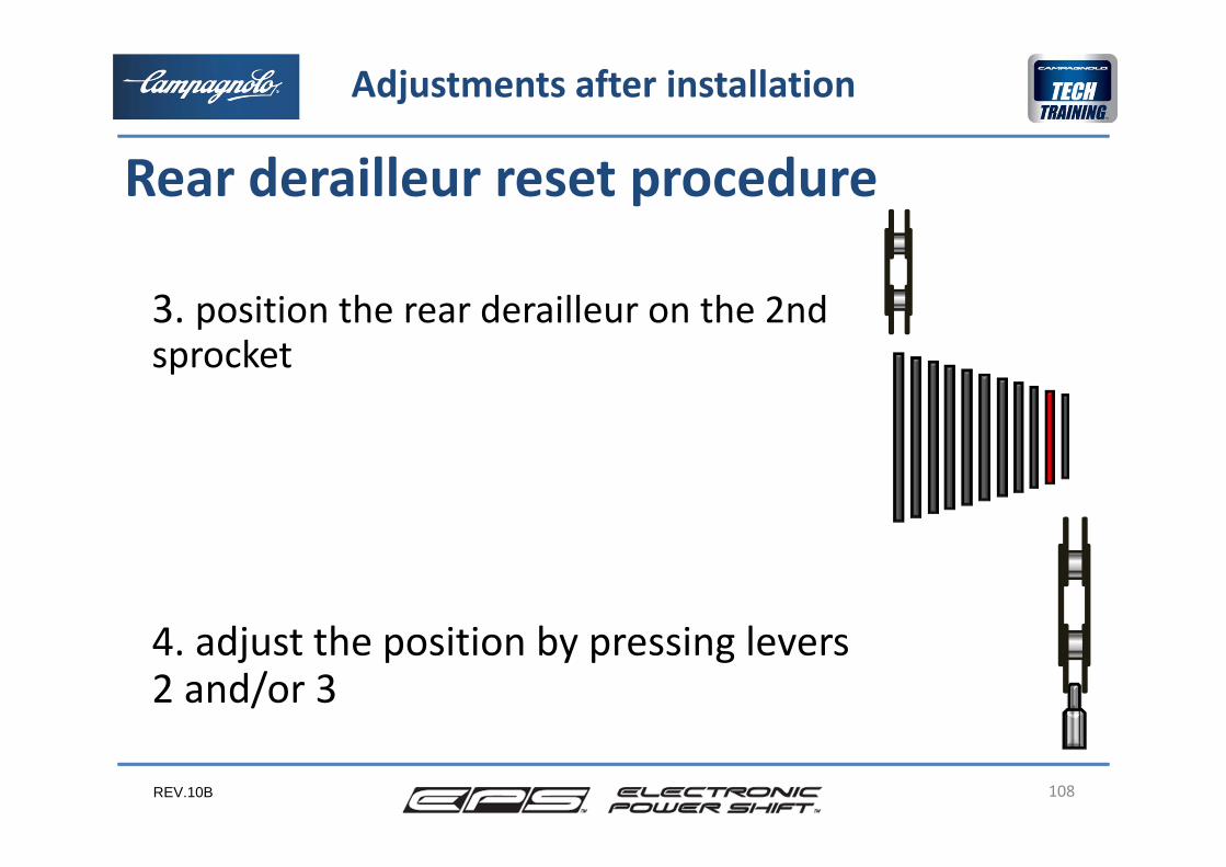
3. position the rear derailleur on the 2nd sprocket
4. adjust the position by pressing levers2 and/or 3
108
Adjustments after installation
Rear derailleur reset procedure
REV.10B
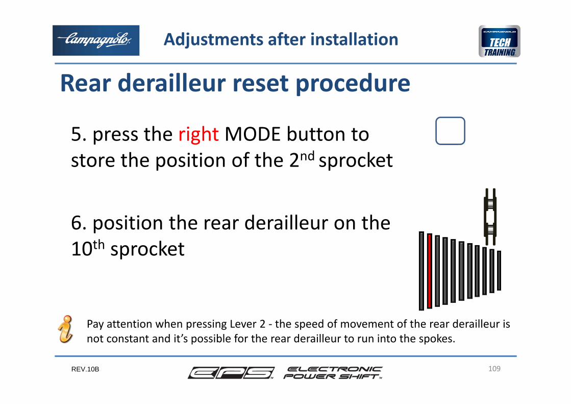
5. press the right MODE button to store the position of the 2nd sprocket
6. position the rear derailleur on the 10th sprocket
109
Rear derailleur reset procedure
Adjustments after installation
Pay attention when pressing Lever 2 ‐ the speed of movement of the rear derailleur isnot constant and it’s possible for the rear derailleur to run into the spokes.
REV.10B
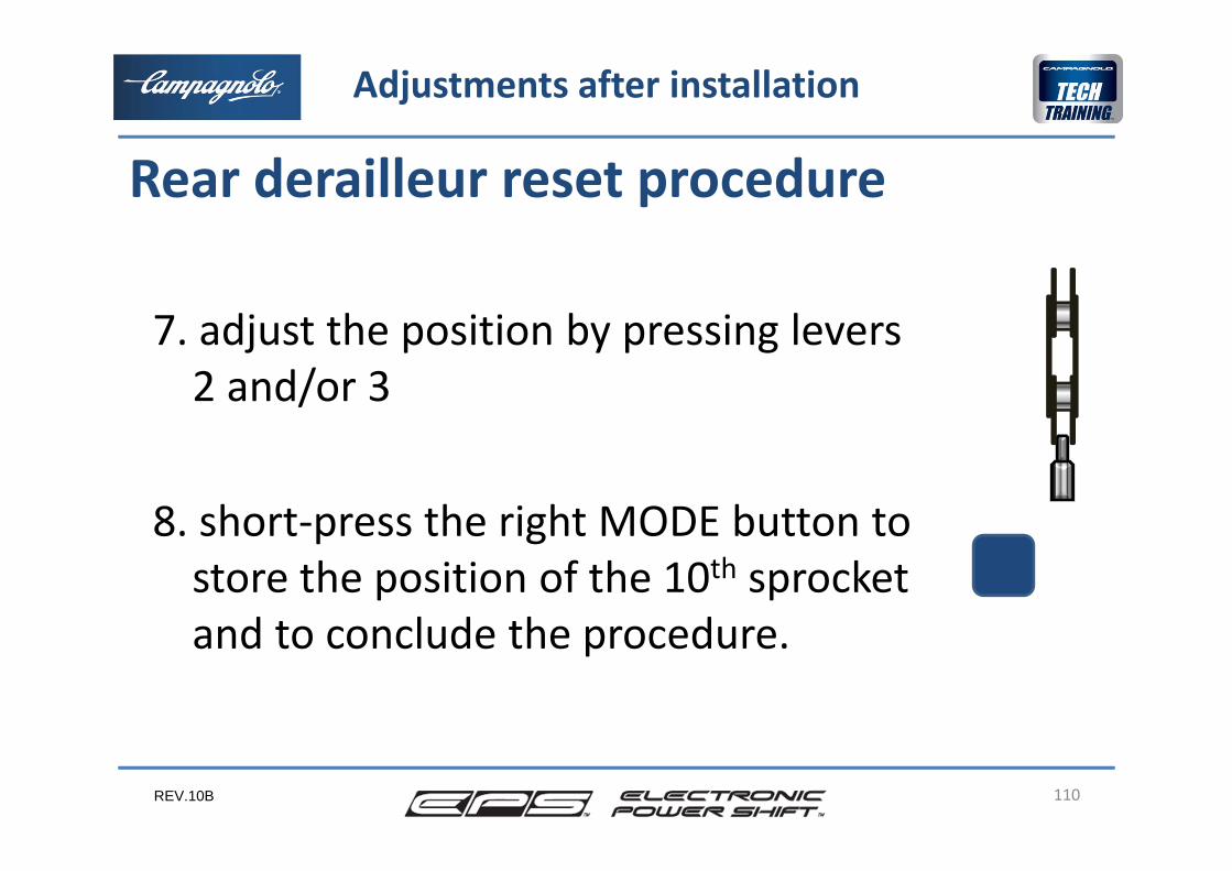
7. adjust the position by pressing levers2 and/or 3
8. short‐press the right MODE button to store the position of the 10th sprocketand to conclude the procedure.
110
Rear derailleur reset procedure
Adjustments after installation
REV.10B
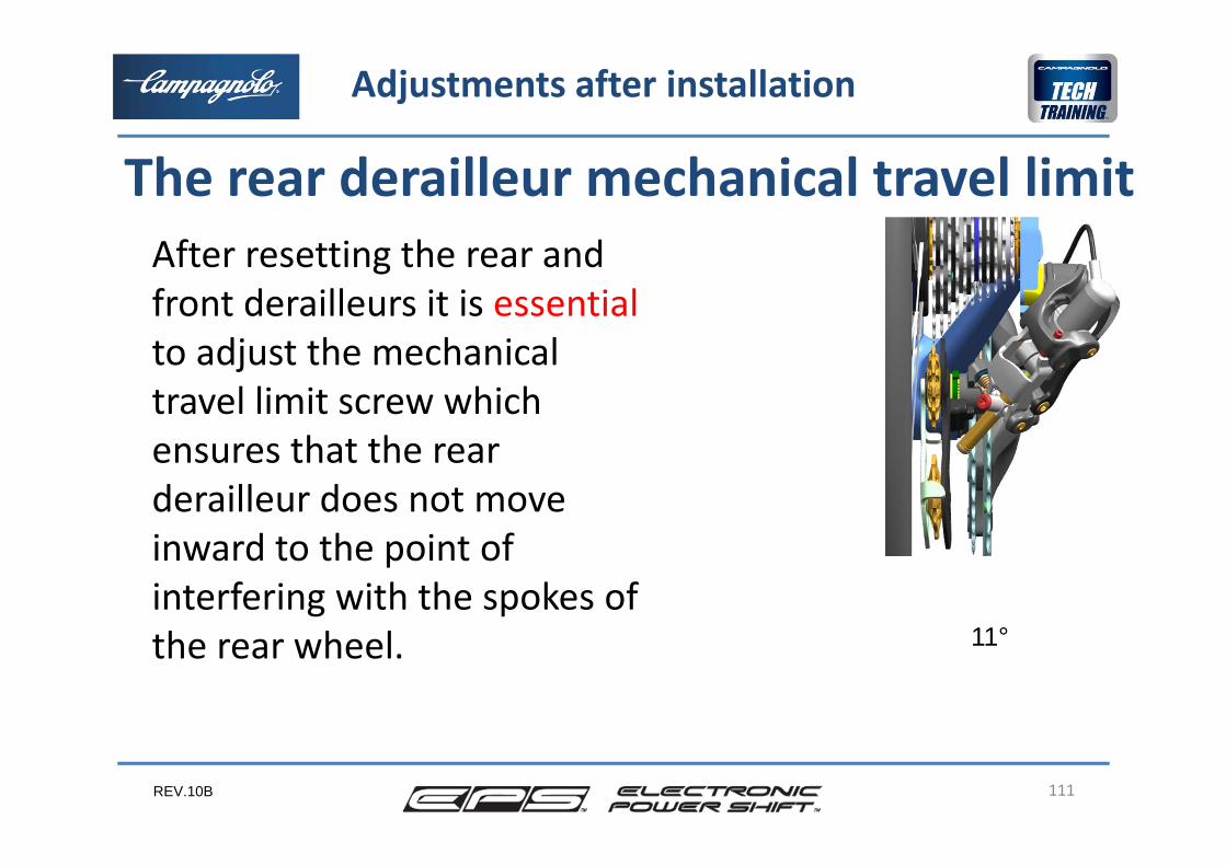
After resetting the rear and front derailleurs it is essentialto adjust the mechanical travel limit screw which ensures that the rear derailleur does not move inward to the point of interfering with the spokes of the rear wheel.
111
The rear derailleur mechanical travel limit
Adjustments after installation
11°
REV.10B
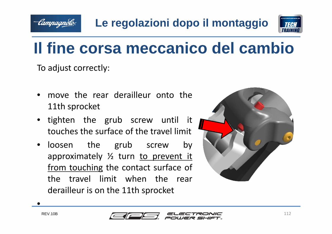
To adjust correctly:
• move the rear derailleur onto the11th sprocket
• tighten the grub screw until ittouches the surface of the travel limit
• loosen the grub screw byapproximately ½ turn to prevent itfrom touching the contact surface ofthe travel limit when the rearderailleur is on the 11th sprocket
•
Il fine corsa meccanico del cambioLe regolazioni dopo il montaggio
112
REV.10B
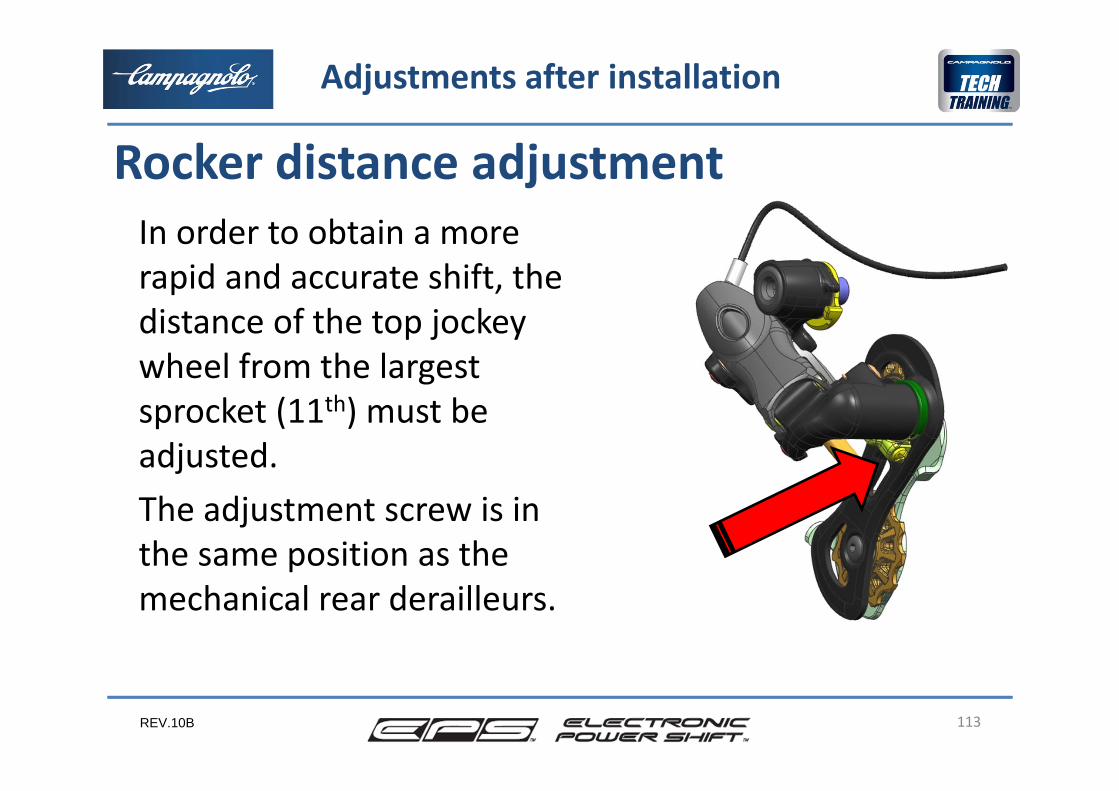
In order to obtain a more rapid and accurate shift, the distance of the top jockey wheel from the largest sprocket (11th) must be adjusted.The adjustment screw is in the same position as the mechanical rear derailleurs.
113
Rocker distance adjustment
Adjustments after installation
REV.10B 114
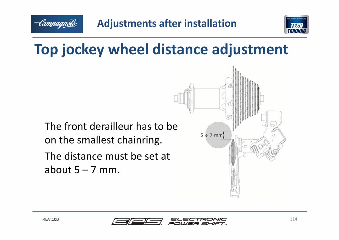
Top jockey wheel distance adjustment
Adjustments after installation
The front derailleur has to be on the smallest chainring.The distance must be set atabout 5 – 7 mm.
REV.10B 115
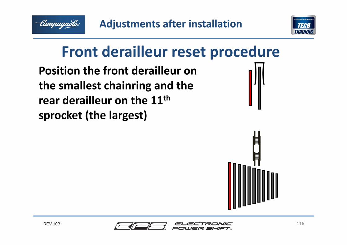
Front derailleur reset procedure
In this procedure we position the front derailleur on the smallest chainring and the rear derailleur on the 11th sprocket (the largest).
Adjust the distance of the inside plate of the front derailleur cage from the inside surface of the chain to 0.5 mm.
Starting from this position, the system calculates the position of the largest chainring and all of the proportional travel based on the position requested by the user.
Adjustments after installation
REV.10B 116
Front derailleur reset procedure Position the front derailleur on the smallest chainring and the rear derailleur on the 11thsprocket (the largest)
Adjustments after installation
REV.10B
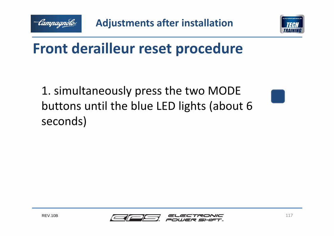
1. simultaneously press the two MODE buttons until the blue LED lights (about 6 seconds)
117
Front derailleur reset procedure
Adjustments after installation
REV.10B
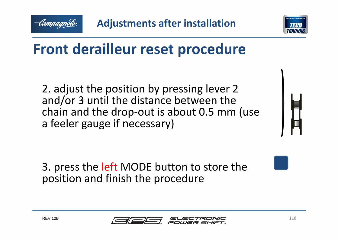
2. adjust the position by pressing lever 2 and/or 3 until the distance between the chain and the drop‐out is about 0.5 mm (use a feeler gauge if necessary)
3. press the left MODE button to store the position and finish the procedure
118
Front derailleur reset procedure
Adjustments after installation
REV.10B
In the event that, after entering the rear or front derailleur reset phase, the MODE button is notshort‐pressed to finish the procedure, the procedure will not end and will remain active.The system operates but movement of the rear or front derailleur is continuous and not in steps, asin normal operation.It is ABSOLUTELY necessary to exit the procedure and carry out the reset again if required
119
Failure to finish reset
Adjustments after installation
REV.10B
The next phase is to check that the transmission works correctly on the road.If the shifting isn’t perfect on the road, it may be necessary to make the adjustment of the rear or/and front derailleur as seen in the first chapter.If the system still doesn’t work perfectly, repeat the resetting of the rear or/and front derailleur.
120
Conclusion
Adjustments after installation
REV.10B 121
4
2
3
5
Maintenance
1
6
• Routine maintenance• Special maintenance
REV.10B
Although the system meets the IP67 standards of water infiltration resistance, we would notrecommend washing the bicycle with pressurisedwater and aggressive detergents.Periodically clean and lubricate the pivots of the derailleurs with a suitable oil for thermo‐plasticcomponentsNever use denatured alcohol to clean the power unit.
122
Cleaning
Maintenance
Routine maintenance
REV.10B
If the cover of the battery charger connector is notcorrectly positioned, water or dirty can go inside the connector.This is not a problem while you are riding, but if youcharge the battery you can create electrical short cutsdamaging the power unit or the battery could not be charged for anormal contacts. So before charging the battery, be sure the connectoris dry and clean.
123
Cleaning
Maintenance
Routine maintenance
REV.10B
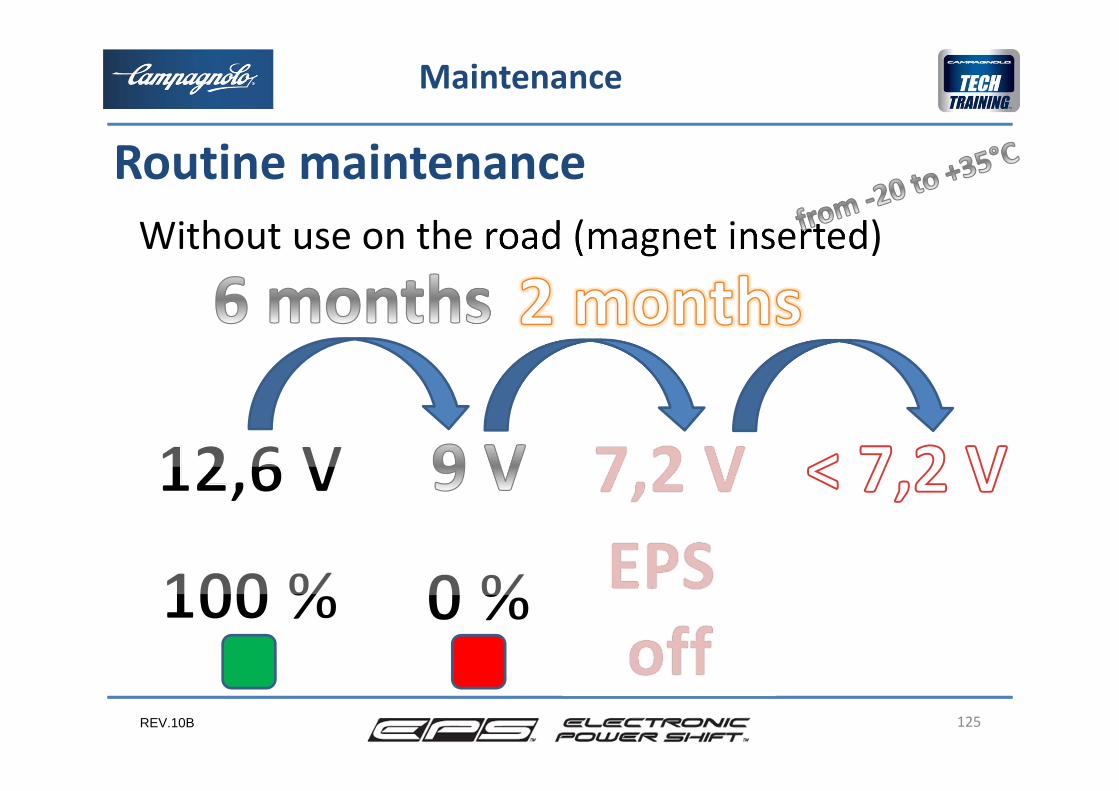
Power systemIn order to prevent damage to the system battery pack, the system automatically switches off when it reaches 9 Volts to prevent dropping under this voltage.If 7.2 Volts are reached, the system also shuts down other electronic components to prevent further energy absorption, protecting the battery from damage
124
Routine maintenance
Maintenance
REV.10B
Without use on the road (magnet inserted)
125
Routine maintenance
Maintenance
REV.10B
We therefore strongly recommend recharging the battery once the interface LED turns off.The times indicated in the previous outline relate to temperatures up to 35°C and can drop significantly with an increase in temperature. Therefore storage of the power unit or the complete bicycle at a higher temperature for several months is not recommended.
126
Routine maintenance
Maintenance
REV.10B
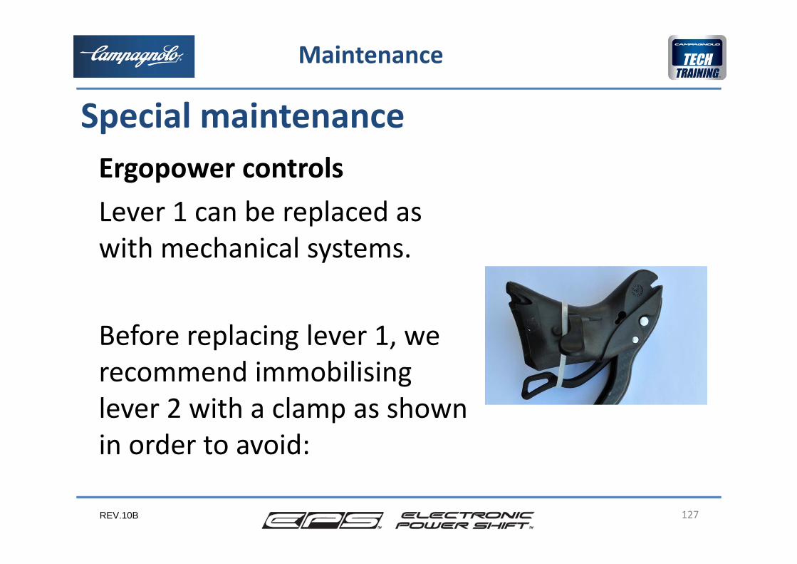
Ergopower controlsLever 1 can be replaced aswith mechanical systems.
Before replacing lever 1, we recommend immobilising lever 2 with a clamp as shown in order to avoid:
127
Special maintenance
Maintenance
REV.10B
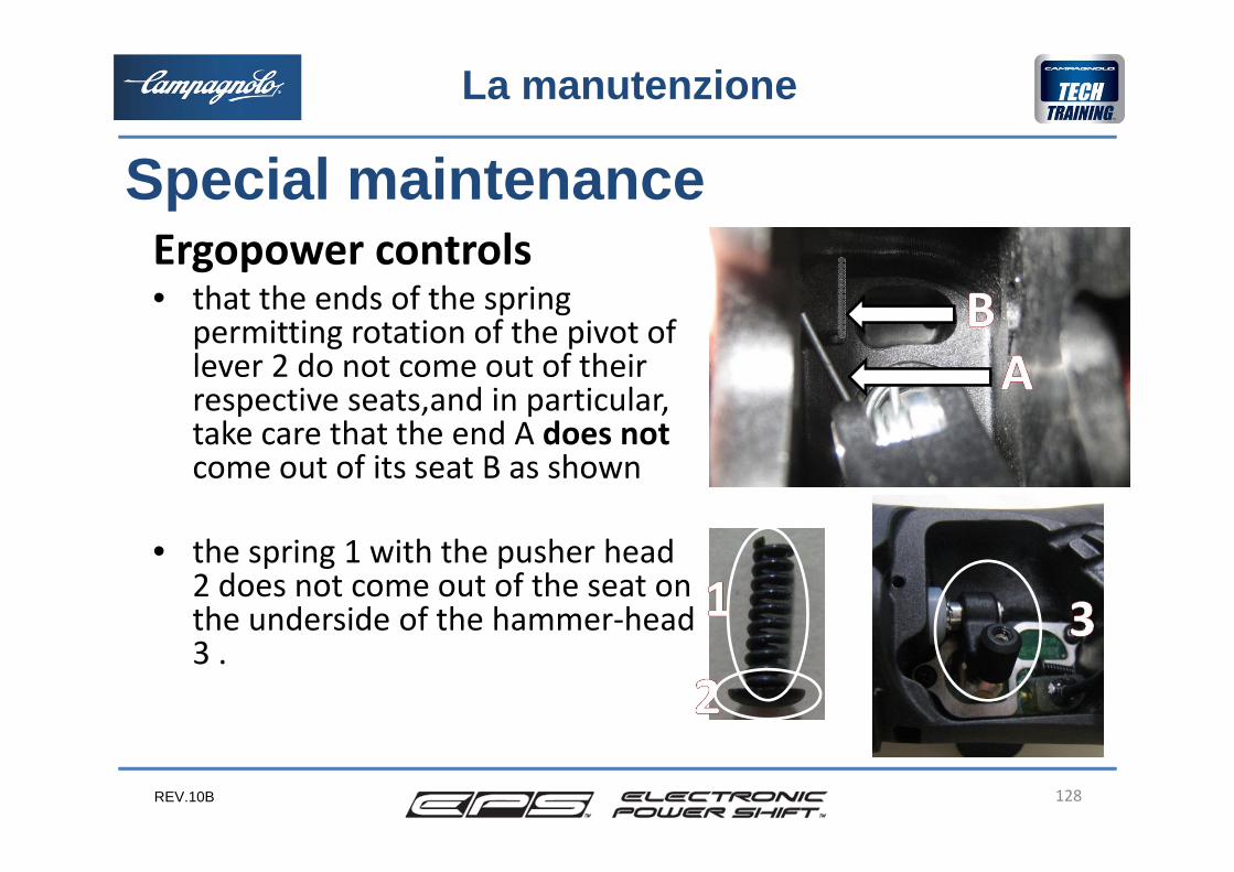
Ergopower controls• that the ends of the spring
permitting rotation of the pivot of lever 2 do not come out of their respective seats,and in particular, take care that the end A does notcome out of its seat B as shown
• the spring 1 with the pusher head 2 does not come out of the seat on the underside of the hammer‐head 3 .
Special maintenanceLa manutenzione
128
REV.10B
Il montaggio
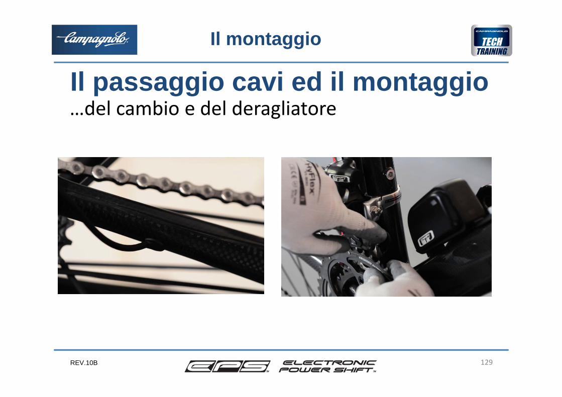
Il passaggio cavi ed il montaggio…del cambio e del deragliatore
129
REV.10B
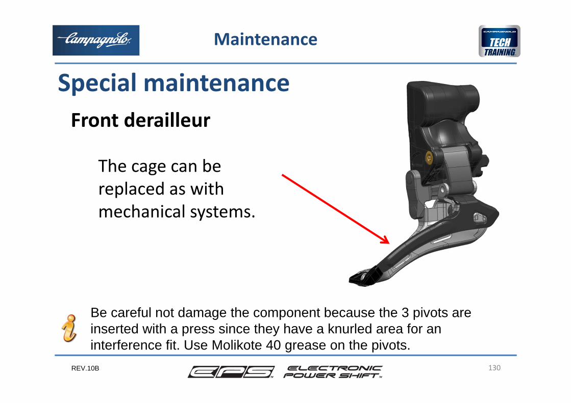
Front derailleur
130
Special maintenance
Maintenance
The cage can be replaced as with mechanical systems.
Be careful not damage the component because the 3 pivots are inserted with a press since they have a knurled area for an interference fit. Use Molikote 40 grease on the pivots.
REV.10B 131
5
2
3
4
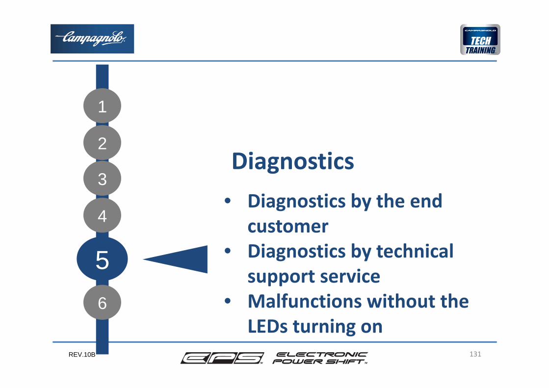
Diagnostics • Diagnostics by the end
customer• Diagnostics by technical
support service• Malfunctions without the
LEDs turning on
1
6
REV.10B
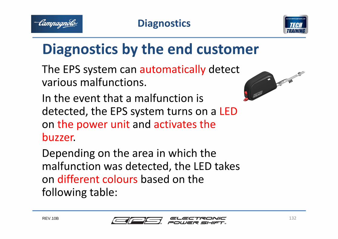
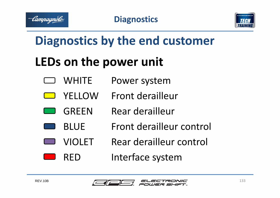
The EPS system can automatically detectvarious malfunctions.In the event that a malfunction isdetected, the EPS system turns on a LEDon the power unit and activates the buzzer.Depending on the area in which the malfunction was detected, the LED takeson different colours based on the following table:
132
Diagnostics by the end customer
Diagnostics
REV.10B
WHITE Power systemYELLOW Front derailleurGREEN Rear derailleurBLUE Front derailleur controlVIOLET Rear derailleur controlRED Interface system
133
LEDs on the power unit
Diagnostics
Diagnostics by the end customer
REV.10B
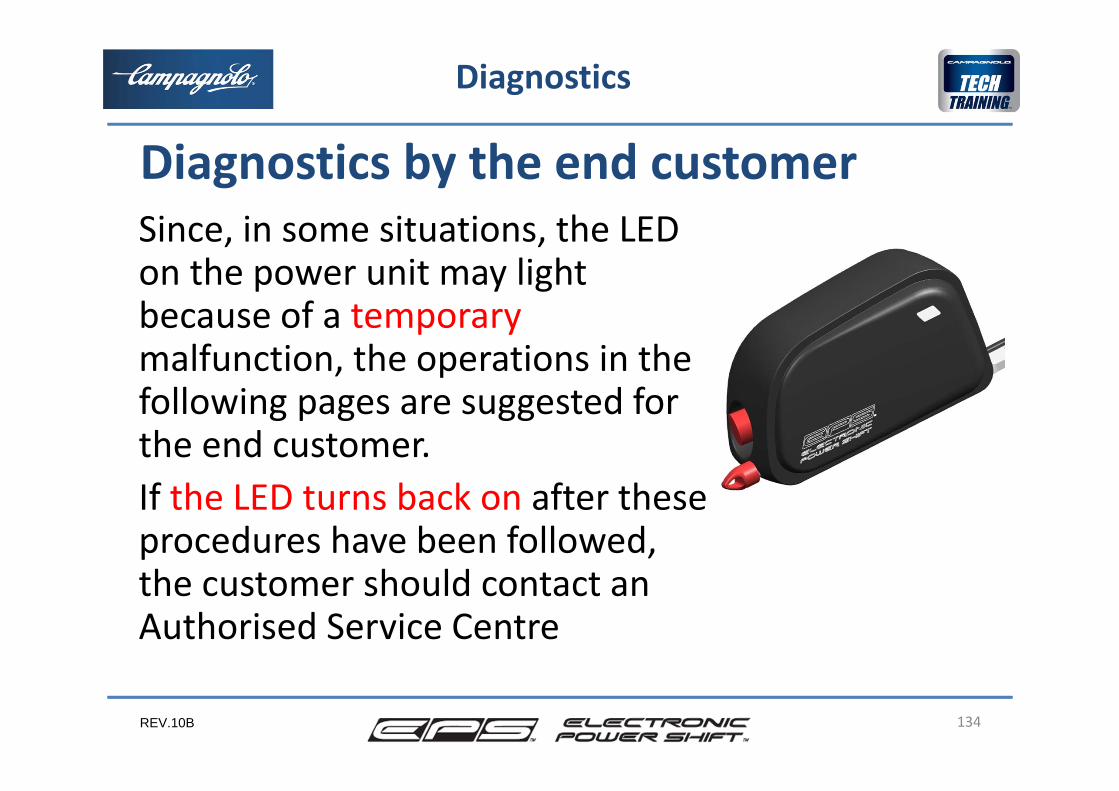
Since, in some situations, the LED on the power unit may light because of a temporarymalfunction, the operations in the following pages are suggested for the end customer. If the LED turns back on after these procedures have been followed, the customer should contact an Authorised Service Centre
134
Diagnostics by the end customer
Diagnostics
REV.10B
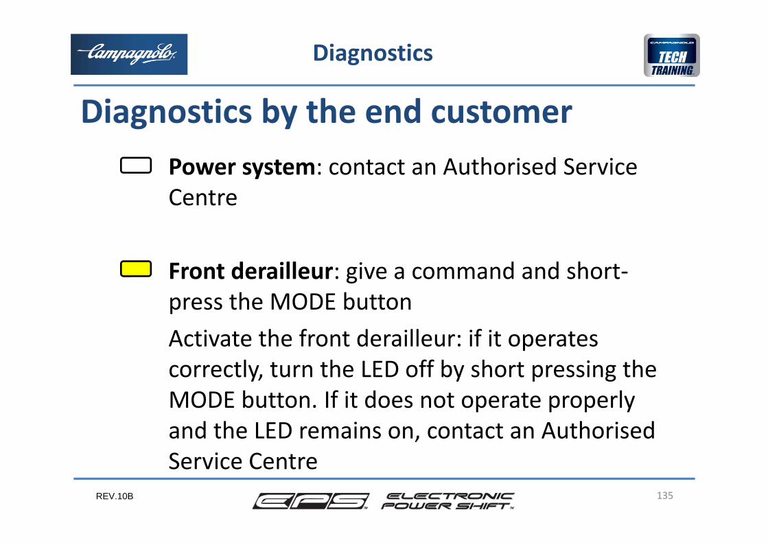
Power system: contact an Authorised Service Centre
Front derailleur: give a command and short‐press the MODE buttonActivate the front derailleur: if it operatescorrectly, turn the LED off by short pressing the MODE button. If it does not operate properlyand the LED remains on, contact an AuthorisedService Centre
135
Diagnostics
Diagnostics by the end customer
REV.10B
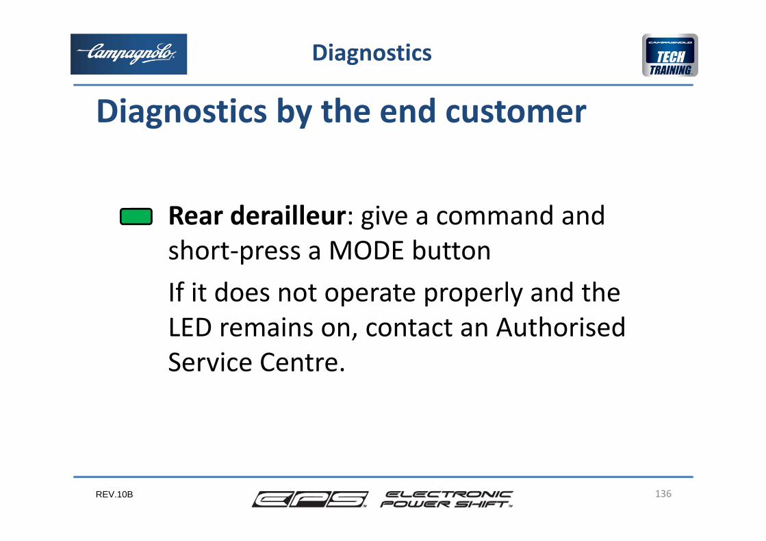
Rear derailleur: give a command and short‐press a MODE buttonIf it does not operate properly and the LED remains on, contact an AuthorisedService Centre.
136
Diagnostics
Diagnostics by the end customer
REV.10B
Rear derailleur control: If lever 2 or 3 was pressed for more than 9 seconds, this LED will light. SOLUTION: short‐press a MODE buttonIf the rear derailleur does not operate properly and the LED remains on afterthis has been done, contact an Authorised Service Centre
137
Diagnostics
Diagnostics by the end customer
REV.10B 138
Diagnostics
Front derailleur control: If lever 2 or 3 waspressed for more than 9 seconds, this LED willlight. SOLUTION: short‐press a MODE button. If the front derailleur then operates correctly, turn the LED off by short‐pressing the MODE button. If it does not operate properly and the LED remains on, contact an AuthorisedService Centre
Diagnostics by the end customer
REV.10B 139
Diagnostics
Interface system: SOLUTION: short‐press a MODE button. If the system still does not operate properly and the LED remains on, contact an AuthorisedService Centre
Diagnostics by the end customer
REV.10B
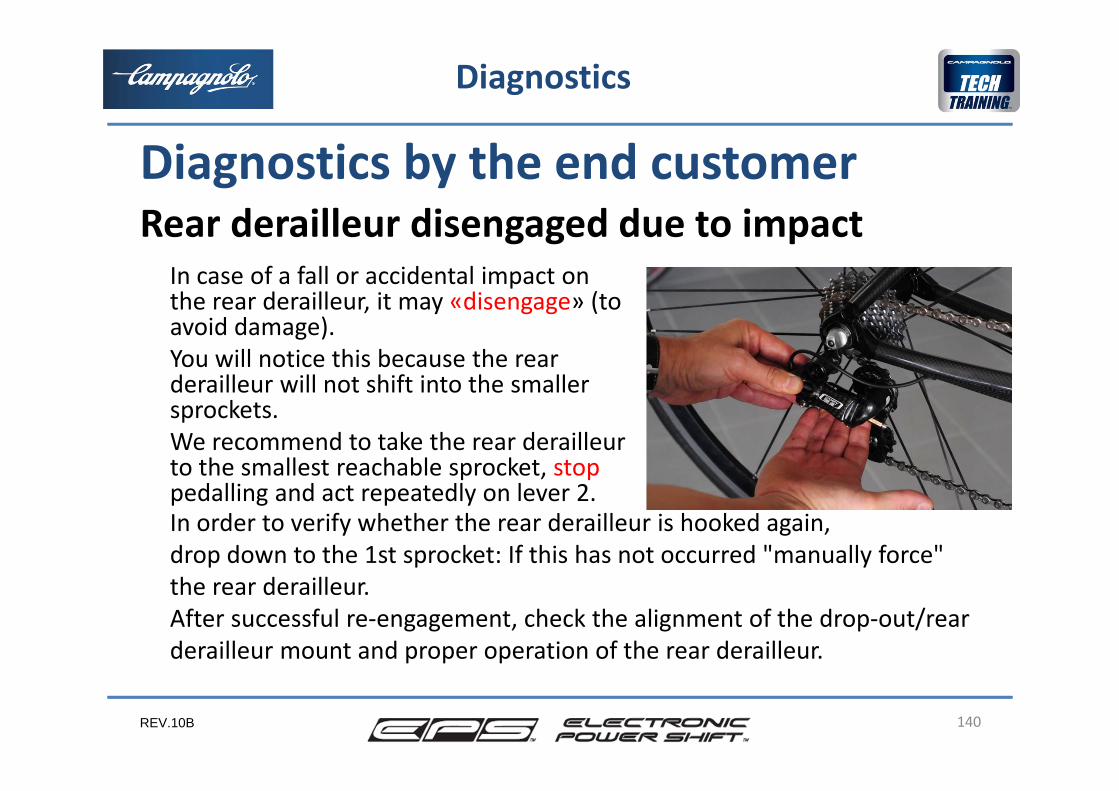
In case of a fall or accidental impact on the rear derailleur, it may «disengage» (to avoid damage).You will notice this because the rearderailleur will not shift into the smallersprockets.We recommend to take the rear derailleur to the smallest reachable sprocket, stoppedalling and act repeatedly on lever 2.
140
Diagnostics
Rear derailleur disengaged due to impactDiagnostics by the end customer
In order to verify whether the rear derailleur is hooked again, drop down to the 1st sprocket: If this has not occurred "manually force"the rear derailleur. After successful re‐engagement, check the alignment of the drop‐out/rear derailleur mount and proper operation of the rear derailleur.
REV.10B
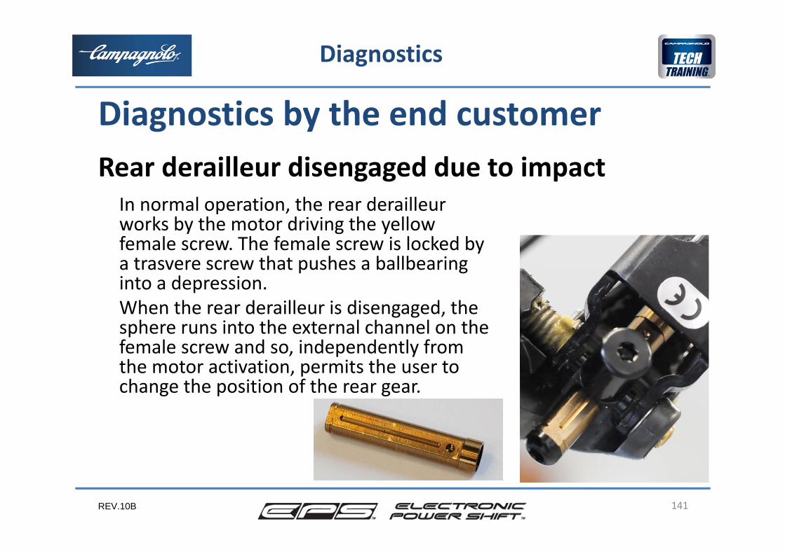
In normal operation, the rear derailleur works by the motor driving the yellow female screw. The female screw is locked by a trasvere screw that pushes a ballbearing into a depression.When the rear derailleur is disengaged, the sphere runs into the external channel on the female screw and so, independently from the motor activation, permits the user to change the position of the rear gear.
141
Diagnostics
Rear derailleur disengaged due to impact
Diagnostics by the end customer
REV.10B
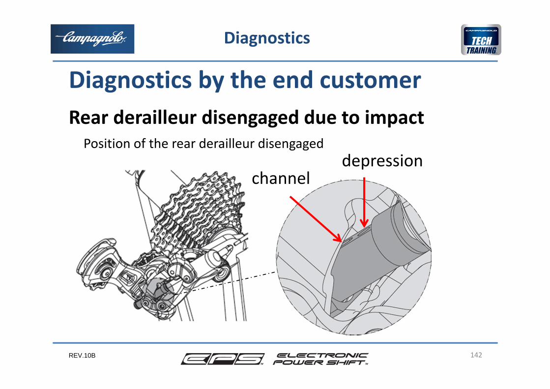
Position of the rear derailleur disengaged
142
Diagnostics
Rear derailleur disengaged due to impact
Diagnostics by the end customer
depressionchannel
REV.10B
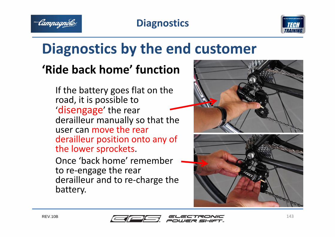
If the battery goes flat on the road, it is possible to ‘disengage’ the rear derailleur manually so that the user can move the rear derailleur position onto any of the lower sprockets.Once ‘back home’ remember to re‐engage the rear derailleur and to re‐charge the battery.
143
Diagnostics
‘Ride back home’ function
Diagnostics by the end customer
REV.10B
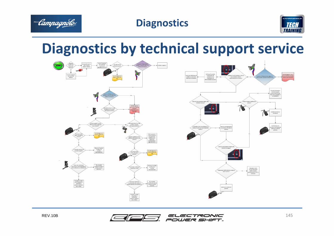
Since in some cases the EPS system is not able to detect a malfunction or the malfunction does not cause the LED on the power unit to light, please follow the EPS fault troubleshooting flow chart. In some cases the chart refers to diagnostics based on the colour of the power unit LED or it indicates the diagnostics to follow where no LED lights.
144
Diagnostics
Diagnostics by technical support service
REV.10B 145
Diagnostics
Diagnostics by technical support service
REV.10B
The procedures which should be followed in the event that a LED on the power unit lights are listed below.
146
Diagnostics
Diagnostics by technical support service
REV.10B
Power systemCAUSE: malfunction of power electronics.SOLUTION: the component must be replaced. Once the new component is installed, since the memory of the rear and front derailleur positions were stored in the original unit, the rear and front derailleur reset procedure must be carried out again.
147
Diagnostics
Diagnostics by technical support service
REV.10B
Front derailleurCAUSES: connector disconnected, damaged cabling (cable or terminal) and / or malfunctioning electric motor.SOLUTION: visually check that the connector is properly connected, disconnect it, check to see whether there are traces of water, dirt, oxidation or abnormalities in the pins and reconnect the connector, after eliminating any abnormalities found. If necessary, use antioxidizing products. If this does not work and the LED remains on, check the entire cable that goes from the front derailleur to the power unit to ensure that there are no cuts, crushed sections or other abnormalities.
148
Diagnostics
Diagnostics by technical support service
REV.10B
Front derailleurIf an abnormality has been detected with the power system cable, replace the power unit. If an abnormality has been detected with the front derailleur cable or if no abnormality is detected, replace the front derailleur.Once the new component is installed, the front derailleur reset procedure must be carried out again.
149
Diagnostics
Diagnostics by technical support service
REV.10B
Rear derailleurCAUSES: connector disconnected, damaged cabling (cable or terminal) or / and malfunctioning electric motor. SOLUTION: visually check that the connector is properly connected, disconnect it, check to see whether there are traces of water, dirt, oxidation or abnormalities in the pins and reconnect the connector, after eliminating any abnormalities found. If necessary use antioxidizing products. If an abnormality has been detected with the power system cable, replace the power unit. If an abnormality has been detected with the rear derailleur cable or if no abnormality is detected, replace the rear derailleur. Once the new component is installed, the rear derailleur reset procedure must be carried out again.
150
Diagnostics
Diagnostics by technical support service
REV.10B
Rear derailleur controlCAUSE: one or more of the 3 circuits remain constantly closed(pressed buttons mechanically ‘stuck’, dome deformed, short circuit in cabling, water causing a short circuit).SOLUTION: check that the control hoods do not press on the leverin an abnormal way or foul levers 2 and 3.Visually check that the connector is properly connected, disconnect it, check to see whether there are traces of water, dirt, oxidation or abnormalities in the pins and reconnect the connector, after eliminating any abnormalities found. If necessaryuse antioxidizing products.
151
Diagnostics
Diagnostics by technical support service
REV.10B
Rear derailleur controlIf it operates correctly, turn the LED off by short‐pressing the MODE button. If an abnormality with the interface system cable hasbeen detected replace the interface system. If an abnormality has been detected to the control cable or if no abnormality was detected replace the control.Once the new component is installed the error must be cancelled by short‐pressing the MODE button.
152
Diagnostics
Diagnostics by technical support service
REV.10B
Front derailleur commandCAUSES: one or more of the 3 circuits remain constantlyclosed (pressed buttons mechanically ‘stuck’, dome deformed, short circuit in cables, water which causes a short circuit).SOLUTION: check that the control hoods do not press on the lever in an abnormal way or foul levers 2 and 3.Visually check that the connector is properly connected, disconnect it, check to see whether there are traces of water, dirt, oxidation or abnormalities in the pins and reconnect the connector, eliminating any abnormalitiesfound. If necessary use antioxidizing products.
153
Diagnostics
Diagnostics by technical support service
REV.10B
Front derailleur controlIf it operates correctly, turn the LED off by short‐pressing the MODE button.
If an abnormality with the interface system cable has beendetected replace the interface system. If an abnormality hasbeen detected to the control cable or if no abnormality wasdetected replace the control.
Once the new component is installed the error must be cancelled by short‐pressing the MODE button.
154
Diagnostics
Diagnostics by technical support service
REV.10B
Interface system:The LED turns on or a fault is detected only when the magnet is initially removed and the system turns on.CAUSE: cable or connector or internal electronics. SOLUTION: Visually check that the connector is properlyconnected, disconnect it, check to see whether there are traces of water, dirt, oxidation or abnormalities in the pins and reconnect the connector once any abnormalityis corrected. Position the magnet in the housing on the power unit, wait more than 30 seconds and remove the magnet: if the LED turns back on, check the entire cablewhich goes ... (ctd)
155
Diagnostics
Diagnostics by technical support service
REV.10B
Interface system... from the interface to the power unit, ensuring that there are no cuts, crushed sections or other abnormalities.If an abnormality is found with the power unit cable replace the power unit. If an abnormality has been detected with the interface system cable, or if no abnormality is detected, replace the power unit.Once the new component is installed the error must be cancelled.
156
Diagnostics
Diagnostics by technical support service
REV.10B
In some cases, as indicated in the troubleshooting chart, electrical malfunctions occur without the LEDs on the power unit turning on:•one or more circuits of the rear and front derailleur are interrupted•battery is completely flat
157
Diagnostics
Malfunctions without the LEDs turning on
REV.10B
One or more circuits of the rear and front derailleur are interrupted:This is the normal situation when the rear or front derailleur control is not being activated by the user, because the switch the control operates is open. Therefore the system does not ‘see’ this as a malfunction. When the defective circuit's lever is activated the system does not activate the requested command because there is an additional break in the circuit. Check the entire cable that goes from the interface to the rear or front derailleur control, ensuring that there are no cuts, crushed sections or other abnormalities.Visually check that the connector is properly connected, disconnect it, check to see whether there are traces of dirt, oxidation or abnormalities in the pins and reconnect the connector after correcting any abnormality.If no abnormality is detected, replace the control.
158
Diagnostics
Malfunctions without the LEDs turning on
REV.10B
Battery is completely flat: The system does not have sufficient energy to indicate the excessively low charge level of the battery.
159
Diagnostics
Malfunctions without the LEDs turning on
REV.10B 160
6
2
3
4
Spare parts and warranty
1
5
• Product options• Accessories• Warranty: terms and
conditions/what is covered• Warranty: management
REV.10B 161
Access., spare parts and warranty
Some components of the EPS system must be chosen based on kind of installation on the frame required and depending on the geographical area where the system will be used:•power system bracket•BB cups•power cable for battery charger
Product options
REV.10B 162
Product options
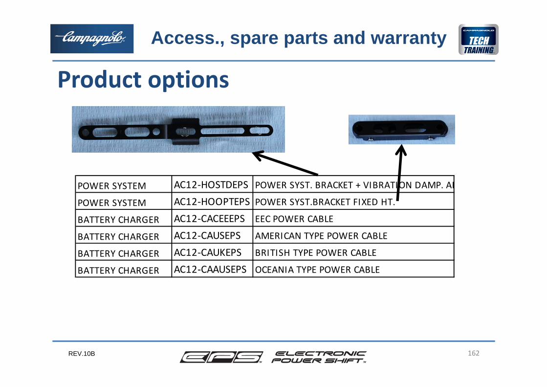
POWER SYSTEM AC12‐HOSTDEPS POWER SYST. BRACKET + VIBRATION DAMP. AB
POWER SYSTEM AC12‐HOOPTEPS POWER SYST.BRACKET FIXED HT.
BATTERY CHARGER AC12‐CACEEEPS EEC POWER CABLE
BATTERY CHARGER AC12‐CAUSEPS AMERICAN TYPE POWER CABLE
BATTERY CHARGER AC12‐CAUKEPS BRITISH TYPE POWER CABLE
BATTERY CHARGER AC12‐CAAUSEPS OCEANIA TYPE POWER CABLE
Access., spare parts and warranty

REV.10B 163
We are producing new cups, to fit the BB cable guide, that are also compatible with mechanical series.
The new cups will be marked: EPS COMPATIBLE.
We’ll also produce new BBright cups (Cervelo)
Product options
Seriesthread / press fit
Code NameMechanical
series compatibility
SUPER RECORD italian OC12‐SRI outboard cups SUPER RECORD™ ULTRA‐TORQUE™ ‐ IT yesSUPER RECORD english OC12‐SRG outboard cups SUPER RECORD™ ULTRA‐TORQUE™ ‐ BSC yes‐ press fit IC12‐SR41 Ultra Torque™ OS‐Fit™ integrated cups 86,5x41 yes‐ press fit IC12‐SR42 Ultra Torque™ OS‐Fit™ integrated cups BB30 68x42 yes‐ press fit IC12‐RE46 Ultra Torque™ OS‐Fit™ integrated cups BB30 68x46 yesRECORD italian OC12‐REI outboard cups RECORD™ ULTRA‐TORQUE™ EPS ‐ IT yesRECORD english OC11‐REG outboard cups RECORD™ ULTRA‐TORQUE™ ‐ BSC yes
Access., spare parts and warranty
REV.10B 164
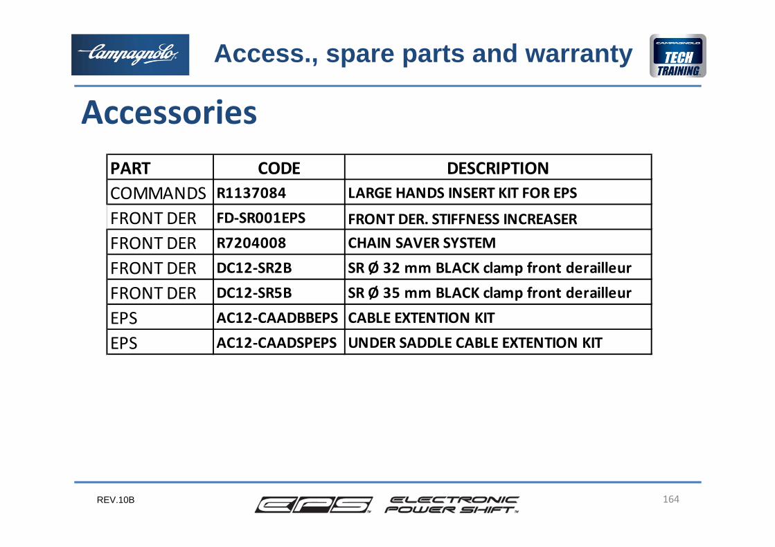
AccessoriesPART CODE DESCRIPTIONCOMMANDS R1137084 LARGE HANDS INSERT KIT FOR EPS
FRONT DER FD‐SR001EPS FRONT DER. STIFFNESS INCREASERFRONT DER R7204008 CHAIN SAVER SYSTEM
FRONT DER DC12‐SR2B SR Ø 32 mm BLACK clamp front derailleur
FRONT DER DC12‐SR5B SR Ø 35 mm BLACK clamp front derailleur
EPS AC12‐CAADBBEPS CABLE EXTENTION KIT
EPS AC12‐CAADSPEPS UNDER SADDLE CABLE EXTENTION KIT
Access., spare parts and warranty
REV.10B 165
Front derailleur mount stiffness increaserIt guarantiees a perfect working of the front derailleur even with ‘brazed on’ type mountings with low stiffness.In particular it’s necessary with carbon frames with carbon ‘brazed on’ mountings, where one can sometimes reach up to 10 mm of movement by forcing the derailleur cage with the hands.
Accessories
Access., spare parts and warranty
REV.10B 166
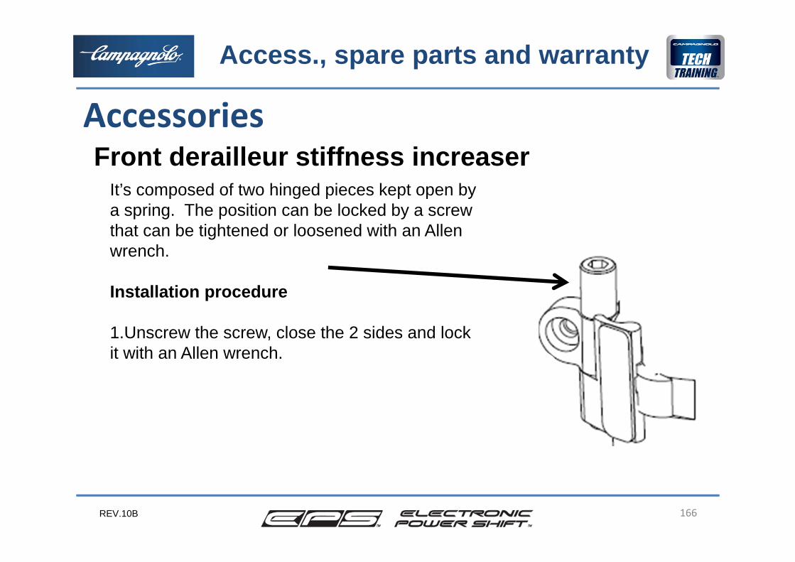
Front derailleur stiffness increaserAccessories
It’s composed of two hinged pieces kept open by a spring. The position can be locked by a screwthat can be tightened or loosened with an Allen wrench.
Installation procedure
1.Unscrew the screw, close the 2 sides and lockit with an Allen wrench.
Access., spare parts and warranty
REV.10B 167
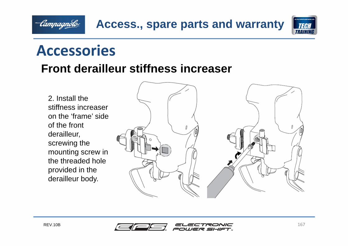
Front derailleur stiffness increaserAccessories
2. Install the stiffness increaseron the ‘frame’ side of the front derailleur, screwing the mounting screw in the threaded holeprovided in the derailleur body.
Access., spare parts and warranty
REV.10B 168
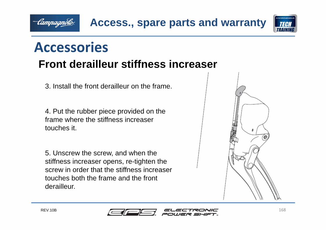
Front derailleur stiffness increaserAccessories
3. Install the front derailleur on the frame.
4. Put the rubber piece provided on the frame where the stiffness increaser touches it.
5. Unscrew the screw, and when the stiffness increaser opens, re-tighten the screw in order that the stiffness increaser touches both the frame and the front derailleur.
Access., spare parts and warranty
REV.10B 169
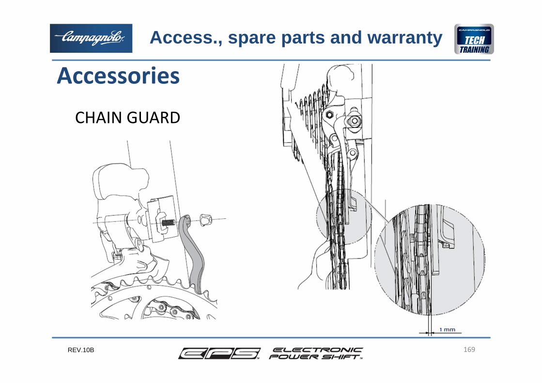
AccessoriesCHAIN GUARD
Access., spare parts and warranty
REV.10B 170
Chain guard
The chain saver system guarantees that, when the chain descends to the smallest chain ring, it doesn’t drop onto the bottom bracket shell, even if external forces push on it.It’s suggested for:•racing use if under pressure the mechanic doesn’t set the front gear correctly•racing use where it may be necessary to shift to the smallest chainring on bends•use of the bike on poor road surfaces or pavè
Accessories
Access., spare parts and warranty
REV.10B 171
Chain guard
It’s compulsary for:•use of the bike on particularly badly surface roads, pavè as in Paris-Roubaix, etc or other cobblestonepaving.
Accessories
Access., spare parts and warranty
REV.10B 172
AccessoriesCABLE EXTENTION KIT
Access., spare parts and warranty
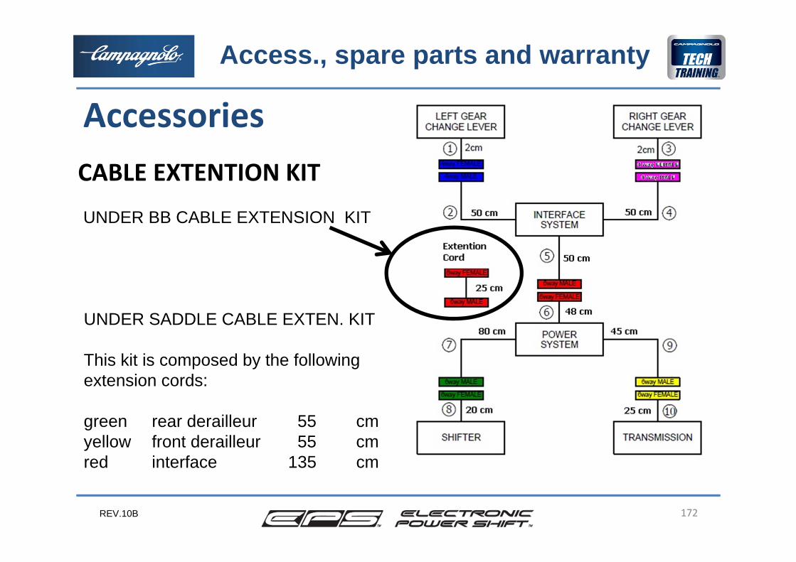
UNDER SADDLE CABLE EXTEN. KIT
This kit is composed by the followingextension cords:
green rear derailleur 55 cmyellow front derailleur 55 cmred interface 135 cm
UNDER BB CABLE EXTENSION KIT
REV.10B 173
Accessories
Access., spare parts and warranty
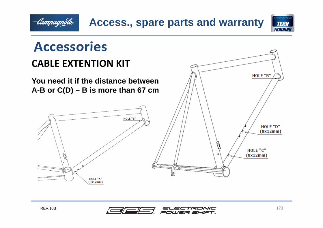
CABLE EXTENTION KITYou need it if the distance betweenA-B or C(D) – B is more than 67 cm
REV.10B 174
WarrantyProcedure for the end customerIn case of malfunction, after having conducted any checks suggested on the instruction sheet, the end customer must contact an Authorised Service Centre for the additional, necessary checks to be carried out, which the ASC is equipped to perform.
Access., spare parts and warranty
REV.10B 175
WarrantyProcedure for the dealer/Pro ShopIn the event that malfunctions are found after having conducted the prescribed checks, the dealer or Pro Shop sends the defective component, after reporting, to the Authorised Service Center in their country.Together with the component, the dealer or Pro Shop also sends the EPS Check Control document, filled in as far as the customer and dealer / Pro Shop are concerned.
Access., spare parts and warranty
REV.10B 176
Warranty3 year warrantyThe Record EPS and Super Record EPS groups, in addition to the 2 year warranty (or 3 for chainset, chain and sprocket), have a warranty extention of 1 year, power unit excluded, if:•they are used on the same bicycle•they are registered on the Campagnolo web site•the components subject to wear are replacedwith Campagnolo components.
Access., spare parts and warranty
REV.10B 177
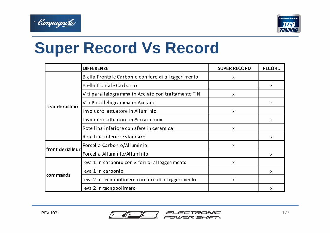
DIFFERENZE SUPER RECORD RECORD
Biella Frontale Carbonio con foro di alleggerimento x
Biella frontale Carbonio x
Viti parallelogramma in Acciaio con trattamento TIN x
Viti Parallelogramma in Acciaio x
Involucro attuatore in Alluminio x
Involucro attuatore in Acciaio Inox x
Rotell ina inferiore con sfere in ceramica x
Rotell ina inferiore standard x
Forcella Carbonio/Alluminio x
Forcella Alluminio/Alluminio x
leva 1 in carbonio con 3 fori di alleggerimento x
leva 1 in carbonio x
leva 2 in tecnopolimero con foro di alleggerimento x
leva 2 in tecnopolimero x
rear derailleur
front derialleur
commands
Super Record Vs Record
REV.10B 178
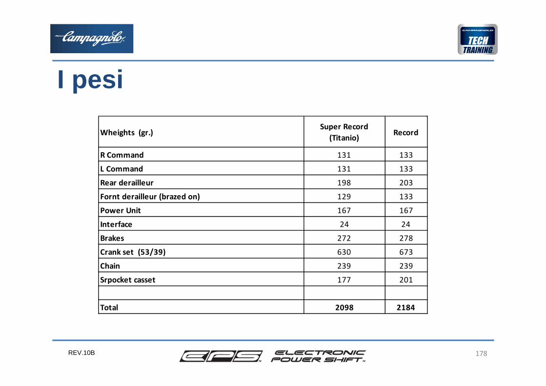
Wheights (gr.)Super Record
(Titanio) Record
R Command 131 133
L Command 131 133
Rear derailleur 198 203
Fornt derailleur (brazed on) 129 133
Power Unit 167 167
Interface 24 24
Brakes 272 278
Crank set (53/39) 630 673
Chain 239 239
Srpocket casset 177 201
Total 2098 2184
I pesi
REV.10B 179
Thank you for your attention