Embed Size (px)
Citation preview
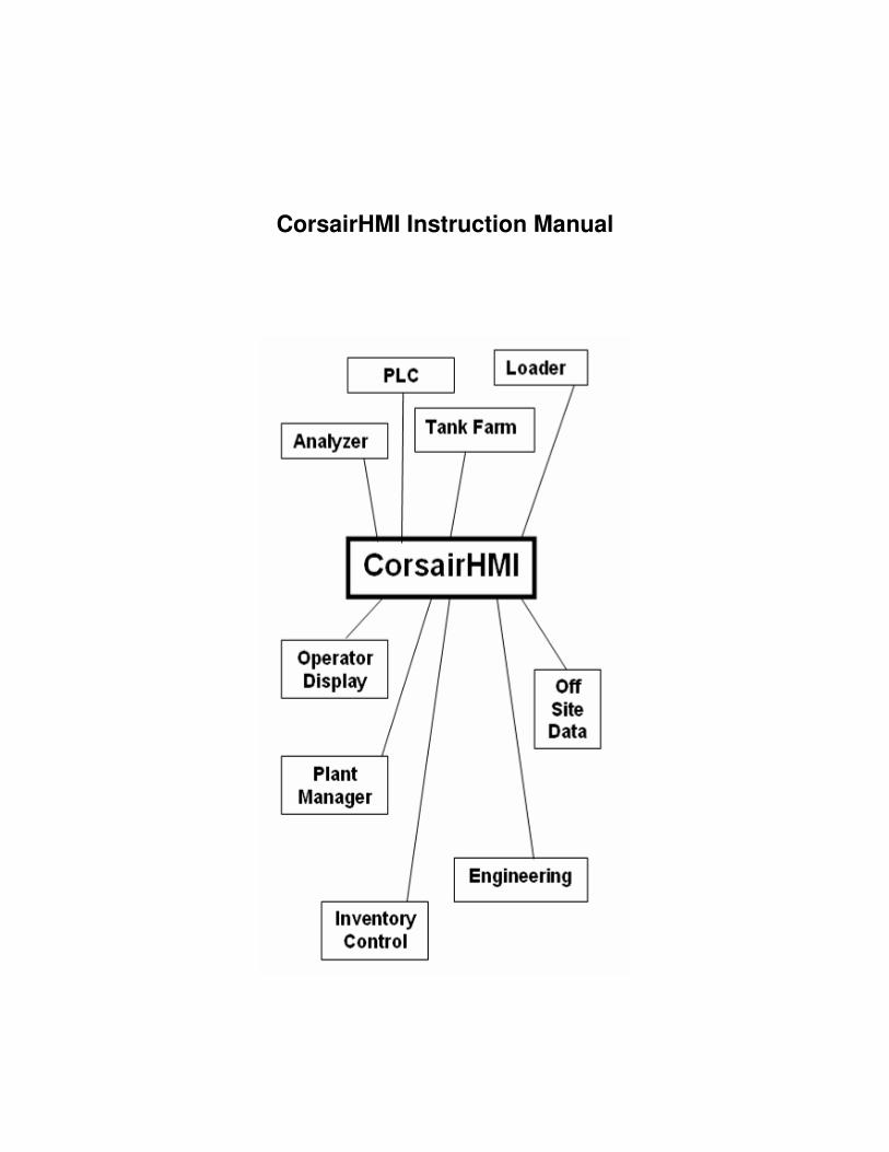
CorsairHMI Instruction Manual
0
CorsairHMI Instruction Manual
Table Of Contents
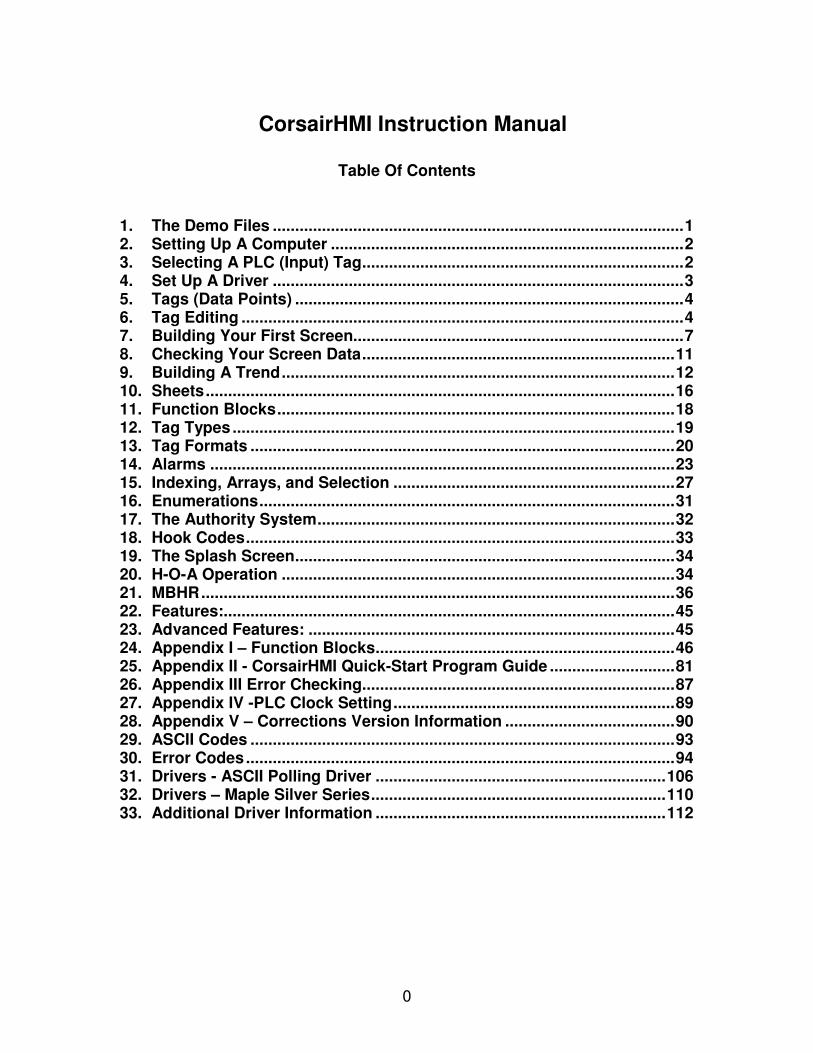
1. The Demo Files ............................................................................................1 2. Setting Up A Computer ...............................................................................2 3. Selecting A PLC (Input) Tag........................................................................2 4. Set Up A Driver ............................................................................................3 5. Tags (Data Points) .......................................................................................4 6. Tag Editing ...................................................................................................4 7. Building Your First Screen..........................................................................7 8. Checking Your Screen Data......................................................................11 9. Building A Trend........................................................................................12 10. Sheets.........................................................................................................16 11. Function Blocks.........................................................................................18 12. Tag Types...................................................................................................19 13. Tag Formats ...............................................................................................20 14. Alarms ........................................................................................................23 15. Indexing, Arrays, and Selection ...............................................................27 16. Enumerations.............................................................................................31 17. The Authority System................................................................................32 18. Hook Codes................................................................................................33 19. The Splash Screen.....................................................................................34 20. H-O-A Operation ........................................................................................34 21. MBHR..........................................................................................................36 22. Features:.....................................................................................................45 23. Advanced Features: ..................................................................................45 24. Appendix I – Function Blocks...................................................................46 25. Appendix II - CorsairHMI Quick-Start Program Guide ............................81 26. Appendix III Error Checking......................................................................87 27. Appendix IV -PLC Clock Setting...............................................................89 28. Appendix V – Corrections Version Information ......................................90 29. ASCII Codes ...............................................................................................93 30. Error Codes................................................................................................94 31. Drivers - ASCII Polling Driver .................................................................106 32. Drivers – Maple Silver Series..................................................................110 33. Additional Driver Information .................................................................112
1
1. The Demo Files
There are several demo files listed on the web site. An easy way to get started to download a demo file. The demo file will contain a demo copy of CorsairHMI. You may want to work with this for a while, but when you get ready to go live you will want to use your distribution copy. To start the demo simply download and save it into a subdirectory. I suggest that you make a subdirectory called C:\CorsairHMI\Demo\. Switch to t\your subdirectory and start CorsairHMI.exe. To start the tutorial, click on Run. Once you are ready to go live with your own program, you may copy all of the files EXCEPT the CorsairHMI.exe and any file ending in .cky to your actual CorsairHMI running directory. CorsairHMI Key Commands Development Mode: F1 - Find/Go To/Development Help F2 – Edit (or Left Click) F3 - Tag Edit (also Trend, etc.) F4 – Create (or INS) F5 - Clone F6 - Edit record mode F7 – Zoom (or ‘Z’) Ctl-R - Field rotate In Screen mode the “Tab” skips to the next graphic object. The “Backspace” skips to the last object. The “T” key transports the selected objects to another screen. Use the Junk Screen to transport multiple objects or build animations. Run Mode: “A” go to Alarm Screen in run mode. Space Bar – Jump to Graphic showing alarm placement. Ctl-F6 – Go to Development Mode You may want to refer to the CorsairHMI Quick Reference trifold as handy tool during development.
2
2. Setting Up A Computer
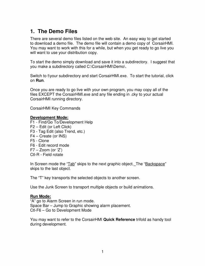
The CorsairHMI application contains a database of what computers are running the CorsairHMI program using the application. There must be at least one computer in this database. From the main menu pick Edit/Data/Computers. If there are no computers, press ‘Create’ (F4 or Ins) to insert a computer. The F2 key is used to edit the computer name. Note that the program will not run if the computer name does not match the name set under Computer Properties (Setup-Computer Properties-Security-This Computer’s Name). See the section on Multiple and Redundant Systems for additional information.
If a specific screen is to be displayed at startup it is placed in the Screen column. You must also check the box under “Computer Properties” (Setup-Computer Properties-Startup-Display First Screen at Start) if you want the CorsairHMI to automatically display this screen when it is started. The IP address field is used as a place to keep track of the IP addresses of different computers. It does not actually set an address into the computers TCP/IP driver. See the section on security for an explanation of passwords and other advanced security features of CorsairHMI. Passwords may be set at multiple levels including computer, screen, sheet, and programming level. The other fields on this screen will be explained later.
3. Selecting A PLC (Input) Tag
CorsairHMI was originally conceived when the PLC was almost the only Tag that communicated over the plant network. Since that time many other Tags have added communications capability. CorsairHMI still uses the nomenclature “PLC”. Other types of equipment may be used they communicates in one of the many protocols that CorsairHMI drivers can recognize. All of these Tags are called PLC’s even though some may actually be Maple HMI’s, Honeywell Burner controllers or other communicating Tags. Now it is necessary to tell CorsairHMI what equipment you are going to connect to. All types of equipment are called PLC’s even though some may actually be
3
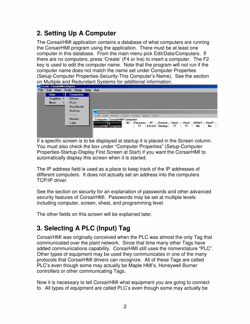
Maple HMI’s, Honeywell Burner controllers or temperature controllers, scales or other equipment. The requirement is that they communicate with protocols that CorsairHMI drivers can recognize. You may name your PLC’s any easily recognizable name. “Boiler 1 Controller”, “Main Tank Subsystem”, or “Reheat Temperature Controller” may all be used as PLC names. If you make them descriptive they will be easier to work with. You should not begin a PLC with a question mark or to put quotation marks anywhere in a tag name. Also avoid the “/” and “\” characters. Select the PLC Equipment:
There are no physical input Tags in your demo file. This was done to avoid having a conflict at a future time
4. Set Up A Driver
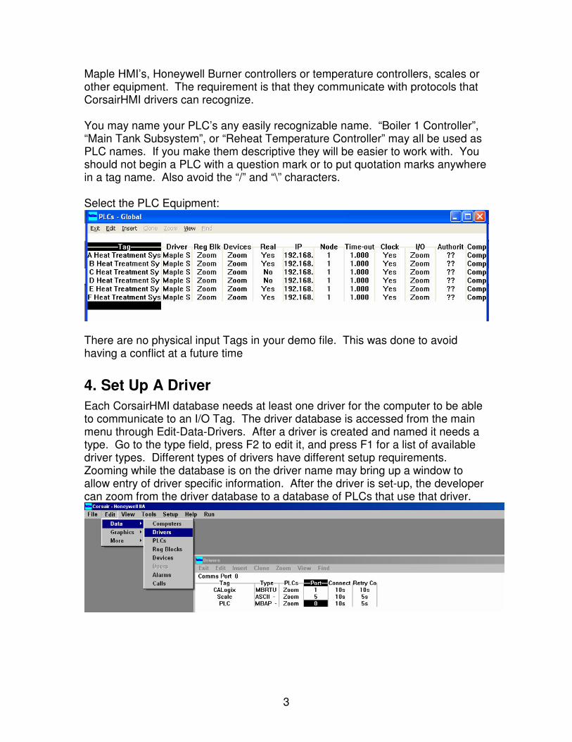
Each CorsairHMI database needs at least one driver for the computer to be able to communicate to an I/O Tag. The driver database is accessed from the main menu through Edit-Data-Drivers. After a driver is created and named it needs a type. Go to the type field, press F2 to edit it, and press F1 for a list of available driver types. Different types of drivers have different setup requirements. Zooming while the database is on the driver name may bring up a window to allow entry of driver specific information. After the driver is set-up, the developer can zoom from the driver database to a database of PLCs that use that driver.
4
5. Tags (Data Points)
Tags are the way the HMI keeps track of and refers to the Data. A tag is the name that you give the Data, so that you may refer to it in graphics, trends, data logs, and other HMI functions. In Corsair HMI a tag may be named anything up to 64 characters long except “??”. The “??” is a special reserved character to tell CorsairHMI that it does not have this tag information. It is best to avoid the “?” character all together. It is of interest to note at this point that traditionally all external I/O devices are referred to as PLC’s. This is because initially HMI’s were designed to give operators “eyes” into the PLC. The name stuck, so you will often see all I/O referred to as a “PLC”. To build the Tag Data Base you will need the address location of all of your data points. CorsairHMI allows you to add Tags freely, but it is good practice to track down the Tag information early in the development cycle. There is no practical limit on the number of tags. CorsairHMI has tested systems with as many as 70,000 tags. The only limits are the amount of memory in your computer and the computer’s speed or ability to process the data. The network speed may also be a consideration.
6. Tag Editing
Tags exist on our external PLC’s as well as internally in CorsairHMI. We need to tell CorsairHMI what data to acquire. Each data point on a PLC is known as a ‘tag’. Each input point or Tag is known by its tag name. Each tag consists of records which contain the information about the tag, such as data source, data type and function block. The tag name is used by screens, trends, data logs, and other objects to display, modify, and log the data. The CorsairHMI application database in linked internally so tags can be renamed at any time without losing references to the data. For instance, “Flow 2” may be renamed “Hot Water Flow” at a future time. and CorsairHMI will use the new tag name instead of the old one. All references to the “Flow 2” data now use “Hot Water Flow” to locate their data. Exception: If you import a screen, sheet etc, it will have the old Tag name in it, and will not know that you changed its name. If you import a screen, you should plan on retagging its data. See “Checking Your Screen Data” for some handy hints. A CorsairHMI application may also contain internal tags which are defined within CorsairHMI. These tags may come from Alarms, MX Plus B, Function Blocks, Sheets, Mini-Programs, Defined Constants, etc. Once they are defined CorsairHMI treats them all the same. Appropriate conversions are made automatically so that they work seamlessly within the program.
5
There are two styles of Tag Editing • Menu Editing (single record) • Spreadsheet Editing (multiple records)
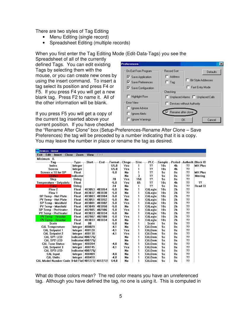
When you first enter the Tag Editing Mode (Edit-Data-Tags) you see the Spreadsheet of all of the currently defined Tags. You can edit existing Tags by selecting them with the mouse, or you can create new ones by using the insert command. To insert a tag select its position and press F4 or F5. If you press F4 you will get a new blank tag. Press F2 to name it. All of the other information will be blank. If you press F5 you will get a copy of the current tag inserted above your current position. If you have checked the “Rename After Clone” box (Setup-Preferences-Rename After Clone – Save Preferences) the tag will be preceded by a number indicating that it is a copy. You may leave the number in place or rename the tag as desired.
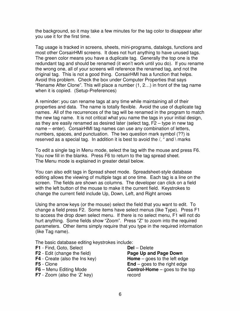
What do those colors mean? The red color means you have an unreferenced tag. Although you have defined the tag, no one is using it. This is computed in
6
the background, so it may take a few minutes for the tag color to disappear after you use it for the first time. Tag usage is tracked in screens, sheets, mini-programs, datalogs, functions and most other CorsairHMI screens. It does not hurt anything to have unused tags. The green color means you have a duplicate tag. Generally the top one is the redundant tag and should be renamed (it won’t work until you do). If you rename the wrong one, all of your screens will reference the renamed tag, and not the original tag. This is not a good thing. CorsairHMI has a function that helps. Avoid this problem. Check the box under Computer Properties that says “Rename After Clone”. This will place a number (1, 2…) in front of the tag name when it is copied. (Setup-Preferences) A reminder: you can rename tags at any time while maintaining all of their properties and data. The name is totally flexible. Avoid the use of duplicate tag names. All of the recurrences of the tag will be renamed in the program to match the new tag name. It is not critical what you name the tags in your initial design, as they are easily renamed as desired later (select tag, F2 – type in new tag name – enter). CorsairHMI tag names can use any combination of letters, numbers, spaces, and punctuation. The two question mark symbol (??) is reserved as a special tag. In addition it is best to avoid the /, “ and \ marks To edit a single tag in Menu mode, select the tag with the mouse and press F6. You now fill in the blanks. Press F6 to return to the tag spread sheet. The Menu mode is explained in greater detail below. You can also edit tags in Spread sheet mode. Spreadsheet-style database editing allows the viewing of multiple tags at one time. Each tag is a line on the screen. The fields are shown as columns. The developer can click on a field with the left button of the mouse to make it the current field. Keystrokes to change the current field include Up, Down, Left, and Right arrows Using the arrow keys (or the mouse) select the field that you want to edit. To change a field press F2. Some items have select menus (like Type). Press F1 to access the drop down select menu. If there is no select menu, F1 will not do hurt anything. Some fields show “Zoom”. Press “Z” to zoom into the required parameters. Other items simply require that you type in the required information (like Tag name). The basic database editing keystrokes include: F1 - Find, Goto, Select F2 - Edit (change the field) F4 - Create (also the Ins key) F5 - Clone F6 – Menu Editing Mode F7 - Zoom (also the ‘Z’ key)
Del – Delete Page Up and Page Down Home – goes to the left edge End – goes to the right edge Control-Home – goes to the top record
7
Control-End – goes to the bottom record When using sheet-style database editing sometimes a data field will be shown in color. This indicates the presence of an error. Clicking on the field will case a description of the error to appear on the status bar on the bottom of the window. Each Tag record includes fields for the type of data, the PLC address of the data, and the format of the data. You can also set whether the data can be changed from Corsair, or it is monitor only. Other fields such as calculation blocks will be explained later.
Caution: There is no UNDO operation for this page, so be careful what you delete
Again, when getting started it may be easier to modify a field than to start from scratch. To modify a field place the mouse over the field and left click. The field will be highlighted. Press “F2” to modify the field name. Press “F6” to modify all other tag parameters. You may also use “Insert” to insert a new record. “Delete” deletes an entire record. Cloning may be used to duplicate a database record. The F5 Clone key creates a copy of the record immediately above the original. If you checked the “Rename after Clone” box under “Setup-Preferences” CorsairHMI will automatically add a 1 (or 2, 3, 4, etc.) in front of the cloned tag. You might want to make sure that this box is checked now. If you do not wish to have the automatic renaming feature activated the tag should then be changed on the copy to avoid a duplicate tag error. Data may be copied up or down from a single field of one record onto another record. Pressing Shift � or Shift � from a field will cause that field’s data to be copied to the record above or below it.
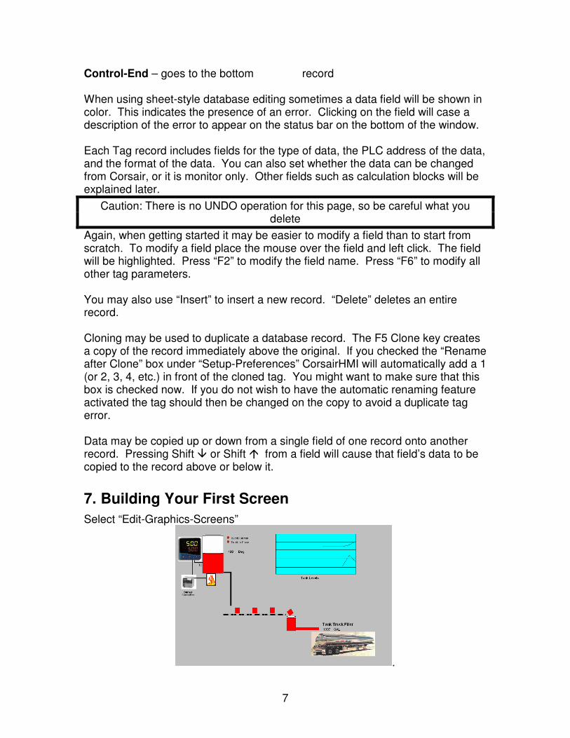
7. Building Your First Screen
Select “Edit-Graphics-Screens”
.
8
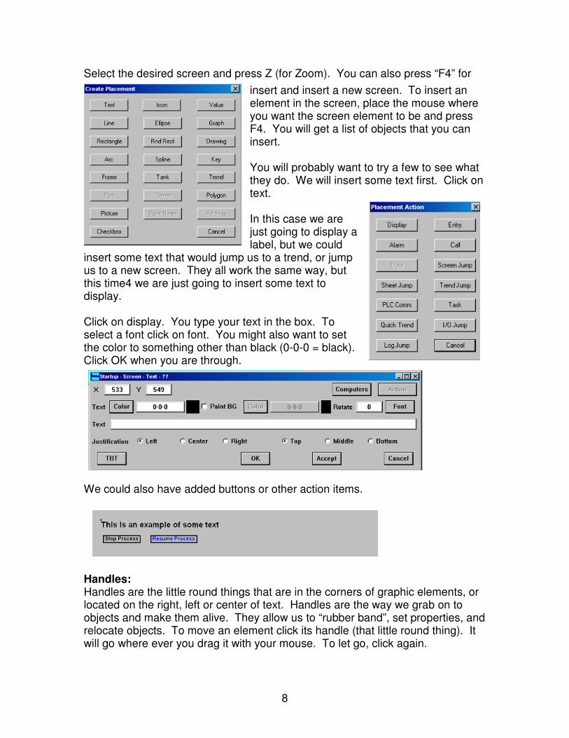
Select the desired screen and press Z (for Zoom). You can also press “F4” for
insert and insert a new screen. To insert an element in the screen, place the mouse where you want the screen element to be and press F4. You will get a list of objects that you can insert. You will probably want to try a few to see what they do. We will insert some text first. Click on text. In this case we are just going to display a label, but we could
insert some text that would jump us to a trend, or jump us to a new screen. They all work the same way, but this time4 we are just going to insert some text to display. Click on display. You type your text in the box. To select a font click on font. You might also want to set the color to something other than black (0-0-0 = black). Click OK when you are through.
We could also have added buttons or other action items.
Handles: Handles are the little round things that are in the corners of graphic elements, or located on the right, left or center of text. Handles are the way we grab on to objects and make them alive. They allow us to “rubber band”, set properties, and relocate objects. To move an element click its handle (that little round thing). It will go where ever you drag it with your mouse. To let go, click again.
9
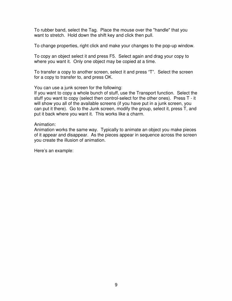
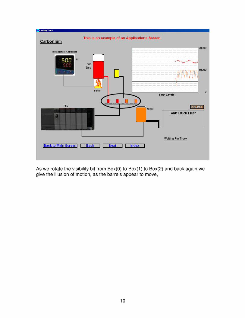
To rubber band, select the Tag. Place the mouse over the "handle" that you want to stretch. Hold down the shift key and click then pull. To change properties, right click and make your changes to the pop-up window. To copy an object select it and press F5. Select again and drag your copy to where you want it. Only one object may be copied at a time. To transfer a copy to another screen, select it and press “T”. Select the screen for a copy to transfer to, and press OK. You can use a junk screen for the following: If you want to copy a whole bunch of stuff, use the Transport function. Select the stuff you want to copy (select then control-select for the other ones). Press T - it will show you all of the available screens (if you have put in a junk screen, you can put it there). Go to the Junk screen, modify the group, select it, press T, and put it back where you want it. This works like a charm. Animation: Animation works the same way. Typically to animate an object you make pieces of it appear and disappear. As the pieces appear in sequence across the screen you create the illusion of animation. Here’s an example:
10
As we rotate the visibility bit from Box(0) to Box(1) to Box(2) and back again we give the illusion of motion, as the barrels appear to move,
11
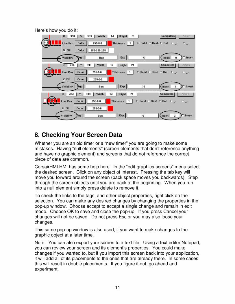
Here’s how you do it:
8. Checking Your Screen Data
Whether you are an old timer or a “new timer” you are going to make some mistakes. Having “null elements” (screen elements that don’t reference anything and have no graphic element) and screens that do not reference the correct piece of data are common.
CorsairHMI HMI has some help here. In the “edit-graphics-screens” menu select the desired screen. Click on any object of interest. Pressing the tab key will move you forward around the screen (back space moves you backwards). Step through the screen objects until you are back at the beginning. When you run into a null element simply press delete to remove it.
To check the links to the tags, and other object properties, right click on the selection. You can make any desired changes by changing the properties in the pop-up window. Choose accept to accept a single change and remain in edit mode. Choose OK to save and close the pop-up. If you press Cancel your changes will not be saved. Do not press Esc or you may also loose your changes.
This same pop-up window is also used, if you want to make changes to the graphic object at a later time.
Note: You can also export your screen to a text file. Using a text editor Notepad, you can review your screen and its element’s properties. You could make changes if you wanted to, but if you import this screen back into your application, it will add all of its placements to the ones that are already there. In some cases this will result in double placements. If you figure it out, go ahead and experiment.
12
You may also want to export your screens and save them as a back-up, or to reuse in another application. Remember you will have to reconnect the Tag Tags if you import it into another application. If you change a Tag name you will have to reconnect this item as well.
9. Building A Trend
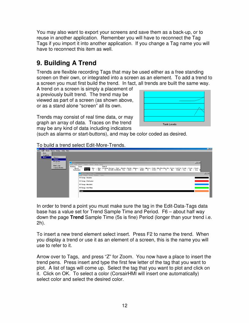
Trends are flexible recording Tags that may be used either as a free standing screen on their own, or integrated into a screen as an element. To add a trend to a screen you must first build the trend. In fact, all trends are built the same way. A trend on a screen is simply a placement of a previously built trend. The trend may be viewed as part of a screen (as shown above, or as a stand alone “screen” all its own. Trends may consist of real time data, or may graph an array of data. Traces on the trend may be any kind of data including indicators (such as alarms or start-buttons), and may be color coded as desired. To build a trend select Edit-More-Trends.
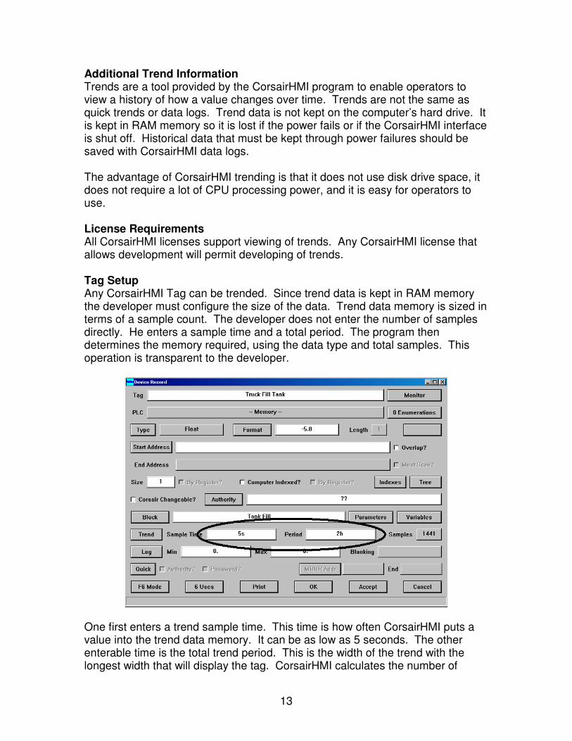
In order to trend a point you must make sure the tag in the Edit-Data-Tags data base has a value set for Trend Sample Time and Period. F6 – about half way down the page Trend Sample Time (5s is fine) Period (longer than your trend i.e. 2h). To insert a new trend element select insert. Press F2 to name the trend. When you display a trend or use it as an element of a screen, this is the name you will use to refer to it. Arrow over to Tags, and press “Z” for Zoom. You now have a place to insert the trend pens. Press insert and type the first few letter of the tag that you want to plot. A list of tags will come up. Select the tag that you want to plot and click on it. Click on OK. To select a color (CorsairHMI will insert one automatically) select color and select the desired color.
13
Additional Trend Information Trends are a tool provided by the CorsairHMI program to enable operators to view a history of how a value changes over time. Trends are not the same as quick trends or data logs. Trend data is not kept on the computer’s hard drive. It is kept in RAM memory so it is lost if the power fails or if the CorsairHMI interface is shut off. Historical data that must be kept through power failures should be saved with CorsairHMI data logs. The advantage of CorsairHMI trending is that it does not use disk drive space, it does not require a lot of CPU processing power, and it is easy for operators to use. License Requirements All CorsairHMI licenses support viewing of trends. Any CorsairHMI license that allows development will permit developing of trends. Tag Setup Any CorsairHMI Tag can be trended. Since trend data is kept in RAM memory the developer must configure the size of the data. Trend data memory is sized in terms of a sample count. The developer does not enter the number of samples directly. He enters a sample time and a total period. The program then determines the memory required, using the data type and total samples. This operation is transparent to the developer.
One first enters a trend sample time. This time is how often CorsairHMI puts a value into the trend data memory. It can be as low as 5 seconds. The other enterable time is the total trend period. This is the width of the trend with the longest width that will display the tag. CorsairHMI calculates the number of
14
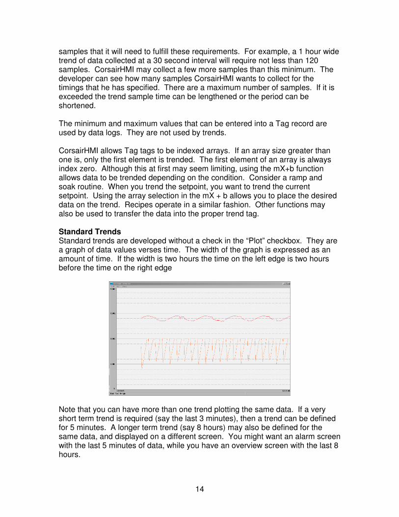
samples that it will need to fulfill these requirements. For example, a 1 hour wide trend of data collected at a 30 second interval will require not less than 120 samples. CorsairHMI may collect a few more samples than this minimum. The developer can see how many samples CorsairHMI wants to collect for the timings that he has specified. There are a maximum number of samples. If it is exceeded the trend sample time can be lengthened or the period can be shortened. The minimum and maximum values that can be entered into a Tag record are used by data logs. They are not used by trends. CorsairHMI allows Tag tags to be indexed arrays. If an array size greater than one is, only the first element is trended. The first element of an array is always index zero. Although this at first may seem limiting, using the mX+b function allows data to be trended depending on the condition. Consider a ramp and soak routine. When you trend the setpoint, you want to trend the current setpoint. Using the array selection in the mX + b allows you to place the desired data on the trend. Recipes operate in a similar fashion. Other functions may also be used to transfer the data into the proper trend tag. Standard Trends Standard trends are developed without a check in the “Plot” checkbox. They are a graph of data values verses time. The width of the graph is expressed as an amount of time. If the width is two hours the time on the left edge is two hours before the time on the right edge
Note that you can have more than one trend plotting the same data. If a very short term trend is required (say the last 3 minutes), then a trend can be defined for 5 minutes. A longer term trend (say 8 hours) may also be defined for the same data, and displayed on a different screen. You might want an alarm screen with the last 5 minutes of data, while you have an overview screen with the last 8 hours.
15
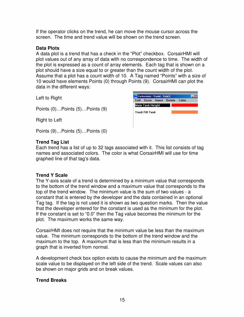
If the operator clicks on the trend, he can move the mouse cursor across the screen. The time and trend value will be shown on the trend screen. Data Plots A data plot is a trend that has a check in the “Plot” checkbox. CorsairHMI will plot values out of any array of data with no correspondence to time. The width of the plot is expressed as a count of array elements. Each tag that is shown on a plot should have a size equal to or greater than the count width of the plot. Assume that a plot has a count width of 10. A Tag named “Points” with a size of 10 would have elements Points (0) through Points (9). CorsairHMI can plot the data in the different ways: Left to Right Points (0)…Points (5)…Points (9) Right to Left Points (9)…Points (5)…Points (0) Trend Tag List Each trend has a list of up to 32 tags associated with it. This list consists of tag names and associated colors. The color is what CorsairHMI will use for time graphed line of that tag’s data. Trend Y Scale The Y-axis scale of a trend is determined by a minimum value that corresponds to the bottom of the trend window and a maximum value that corresponds to the top of the trend window. The minimum value is the sum of two values - a constant that is entered by the developer and the data contained in an optional Tag tag. If the tag is not used it is shown as two question marks. Then the value that the developer entered for the constant is used as the minimum for the plot. If the constant is set to “0.0” then the Tag value becomes the minimum for the plot. The maximum works the same way. CorsairHMI does not require that the minimum value be less than the maximum value. The minimum corresponds to the bottom of the trend window and the maximum to the top. A maximum that is less than the minimum results in a graph that is inverted from normal. A development check box option exists to cause the minimum and the maximum scale value to be displayed on the left side of the trend. Scale values can also be shown on major grids and on break values. Trend Breaks
16
Each trend can show two break lines. A break line is a line that is straight across the trend window to mark a value. The value that is used is the sum of a constant that is entered by the developer and the data contained in an optional Tag tag. CorsairHMI will always draw the break lines if they fall within the trends minimum and maximum limits. Common development practice is to set the constant to -1 to move an unwanted break off the edge of the trend. The developer can separately specify the colors of the two break lines. Grids CorsairHMI can show both major and minor horizontal grid lines on a trend. Major grid lines are solid lines. Minor grids are dashed lines that are located between major grids. A major grid count of 0 results in no major grids. A major grid count of 1 divides the trend in half. A major grid count of 2 divides the trend in thirds. Minor grids do the same thing between major grids. A trend can have minor grids and no major grids. The developer can separately specify the color of the major and minor grids. Trend Authority An authority Tag on a trend can be used to determine a password level requirement to view the trend. Trend Computer List Some CorsairHMI databases run on multiple computers. This computer list is used to define which computers are allowed to view the trend.
10. Sheets
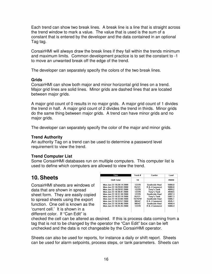
CorsairHMI sheets are windows of data that are shown in spread sheet form. They are easily copied to spread sheets using the export function. One cell is known as the ‘current cell.’ It is shown in a different color. If “Can Edit” is checked the cell can be altered as desired. If this is process data coming from a tag that is not to be changed by the operator the “Can Edit” box can be left unchecked and the data is not changeable by the CorsairHMI operator. Sheets can also be used for reports, for instance a daily or shift report. Sheets can be used for alarm setpoints, process steps, or tank parameters. Sheets can
17
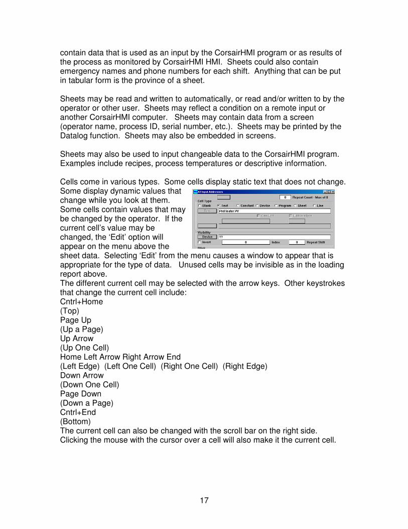
contain data that is used as an input by the CorsairHMI program or as results of the process as monitored by CorsairHMI HMI. Sheets could also contain emergency names and phone numbers for each shift. Anything that can be put in tabular form is the province of a sheet. Sheets may be read and written to automatically, or read and/or written to by the operator or other user. Sheets may reflect a condition on a remote input or another CorsairHMI computer. Sheets may contain data from a screen (operator name, process ID, serial number, etc.). Sheets may be printed by the Datalog function. Sheets may also be embedded in screens. Sheets may also be used to input changeable data to the CorsairHMI program. Examples include recipes, process temperatures or descriptive information. Cells come in various types. Some cells display static text that does not change. Some display dynamic values that change while you look at them. Some cells contain values that may be changed by the operator. If the current cell’s value may be changed, the ‘Edit’ option will appear on the menu above the sheet data. Selecting ‘Edit’ from the menu causes a window to appear that is appropriate for the type of data. Unused cells may be invisible as in the loading report above. The different current cell may be selected with the arrow keys. Other keystrokes that change the current cell include: Cntrl+Home (Top) Page Up (Up a Page) Up Arrow (Up One Cell) Home Left Arrow Right Arrow End (Left Edge) (Left One Cell) (Right One Cell) (Right Edge) Down Arrow (Down One Cell) Page Down (Down a Page) Cntrl+End (Bottom) The current cell can also be changed with the scroll bar on the right side. Clicking the mouse with the cursor over a cell will also make it the current cell.
18
Cells may be used by the operator to start mini-programs that have been written with the CorsairHMI interface programming language. They can also enable the ‘Run’ menu item. Cells are also used to change the window that the operator sees. They enable the ‘Jump’ menu item. The cell may be set to jump to another sheet. Sheets may be set up so that the data in the sheet cells is exported to a comma delimited CSV text file. Menu options will appear when the operator is allowed to do this.
11. Function Blocks
CorsairHMI also uses Tags to do calculations and scaling. An MX + B assigned “Flow Valve A” data might be named “Flow Valve A – Scaled”. In this way the original data is always available for troubleshooting, while the scaled data is used for display, trending and data logging. CorsairHMI has no limit on the number of tags. Calculations may be used for scaling, logical combinations, differential temperature, high and low alarms, look-up tables, linearizations, etc. A variety of calculations are provided in standard CorsairHMI software. Our calculation library continues to expand. Some of the current calculations include: • High Alarm • Lookup Interpolation • Low Alarm • Min Max Scaling • MX Plus B Scaling • Strcat String concatenation • X/D Plus B Scaling • Zero Math mX+B, table look-up, max min, square root. A wide variety of mathematical functions in real time. Time arithmetic provides ramp and soak, integration capability The CorsairHMI program uses program blocks to perform calculations on tagged Tag data. Each calculation requires a tag to identify it. For instance the incoming data may be tagged as Boiler Temperature 101 – Raw. A new tag is generated to allow a calculation or block operation which may be called Boiler Temperature 101 – Scaled. This value may be calculated using a Program Block, and may be scaled as desired, such as degrees C, temperature rise, etc. The tag name may be anything that is of significance to the user. It does not need to reflect the data source tag. Boiler BTUs may be a tag if differential temperature and flow were used to generate BTUs. This value corresponding to the raw data read from the PLC or other Tag is maintained for troubleshooting purposes. It may be in counts, degrees or a non-
19
linearized value. Its value may be forced or used in any other CorsairHMI function. The output from the program block is of the appropriate type. The result of a calculation may be of type float, while the result of alarm comparison is of type indicator. The output from a string block is of type string. Inputs to the block are converted as necessary to the correct type. Some of the current blocks include: · High Alarm – Checks for high limit. Output is of type indicator · Lookup Interpolation – Matches a curve such at TC, Tank, Flowmeter, etc. · Low Alarm – Checks for low limit. Output is of type indicator · Min Max Scaling – Scales between a min and max value. · MX Plus B Scaling – Used for engineering units scaling · Strcat String concatenation – Used to concatenate string values · X/D Plus B Scaling – Used for engineering units scaling with a divisor · Zero – Zeros a value below a certain threshold Standard blocks must be installed into a CorsairHMI application before they can be used. When the development level is set to ‘administrator’ the Tools/Expert/Block menu option leads to a window with two lists. The left-side list has the currently installed standard blocks. The right-side list has the currently configured custom blocks. Standards are installed by default in the CorsairHMI Software. The CorsairHMI application file must be saved after any new standard blocks are installed. There are no required changes to the users application file.
12. Tag Types
CorsairHMI Tag types describe the ways that PLC data is encoded. There are several types for many different purposes. The exact way that each type fits into PLC addresses depends on the type of driver that is used. When a Tag record is created it initially has the “??” (undefined) type. The developer can press F2 on the type field and enter a type. He can also then press F1 to bring up a Tag type selector listing all available types. The ‘indicator’ Tag type is a single-bit logical flag. Indicators can be changed by the PLC and read by the CorsairHMI interface. They indicate on/off conditions. The CorsairHMI program cannot change the status of an indicator. The default text description for the zero state of an indicator is ‘Off’. The description for the one state of an indicator is ‘On’. Tag enumerations can be used to change these descriptions if desired. The ‘switch’ Tag type is also a single-bit logical flag. Switches can be changed by either the PLC or the CorsairHMI interface. When a human operator operates a switch Tag he picks options from a switch operating window.
20
The ‘button’ Tag type is a single of data. The CorsairHMI program turns the bit on to signal to the PLC to do something. The PLC then shuts the bit off. The CorsairHMI operator does not have an option to shut off a button. The ‘HOA’ Tag type is a specialized 3-bit data type. One of the bits is controlled by the PLC. The other two are controlled from the PLC or from the CorsairHMI interface. This type is commonly used in control applications where it is desired to force a motor on or off independently of normal automatic logic. The ‘integer’ Tag type is for a 16-bit integer value. It may be changed by the PLC or by the CorsairHMI program. It may be a signed value ranging from -32768 to +32767. It may be an unsigned value ranging from 0 to 65535. The ‘Double Int’ Tag type is for a 32-bit integer value. It works over a much greater range than the 16-bit integer type. The ‘Float’ Tag type is for a floating point value encoded in IEE standard 32-bit format. The ‘4-bit alarm’ type is for alarm status data arranged in a CorsairHMI standard bit pattern. The ‘1-bit alarm’ type is for another type of alarm status data. The same bit patterns are available for calls. String, Loose String, and Reverse String data types are for encoding of ASCII string data in PLC memory. Each type uses a different scheme for arranging the characters in PLC memory. The choice usually depends on the type of PLC and programming system that it uses. The ‘Cascade’ and ‘Triple Cascade’ types are used for larger-value integer data in PLCs that do not support 32-bit integers. They are useful in cases where integer precision needs to be maintained in totalizing. The Cascade uses two 16-bit registers. The net value is the second register multiplied by 10,000 and then added to the first. A total of 999,999 is possible with a Cascade. A triple cascade can go to 999,999,999. The bit-field types vary from 1 bit to 16. Data encoded in these types is always unsigned and cannot be negative. Bit fields are frequently used to encode sequence options in recipe systems.
13. Tag Formats
Tag numeric formats are entered into the computer with a specification string. ‘-2.2’, ‘U5’, and ‘U,04.1’ are all examples of format specification strings. Each specification string has an associated sample string that the computer can display. Examples of sample strings include ‘-##.##’ and ‘##,###’.
21
The following options may be chosen through the specification string:
Signed versus unsigned data Comma separation of 3 digit groups Leading zero padding Display digit width Display decimal places Implied decimal point position for integer types
Specification: -5 or 5 Sample: -##### A number in the specification shows the number of digits that the computer is to display for the value. The number can be as large as 31. Data is signed by default. This sample occupies 6 character spaces on the screen to allow for a minus sign followed by 5 digits. A 16 bit integer could range in value from -32768 to 32767. A 32-bit double integer would have a much larger range of values. If the value is positive the minus sign in the sample is replaced by a space on the display. Specification: U5 Sample: ##### The letter ‘U’ in a specification stands for unsigned. A 16 bit unsigned integer can range in value from 0 to 65535. No extra space is needed for display of a minus sign. Specification: U,5 Sample: ##,### A comma in a specification tells the computer to break digits to the left of the decimal point into groups of three with commas. Specification: U04 Sample: #### A zero before the digit count in a specification string tells the computer to display the value with Leading Zero Padding. A value of 5 will be displayed as ‘0005’. Zeros will be shown as needed to maintain a 4 digit display. Specification: -2.2 Sample: -##.## Implied decimal points are used with integer data inside PLCs. Care must be taken to not confuse this with floating point data. If a format shows two places to the right of an implied decimal point, an integer value of 123 in the PLC would be displayed as ‘1.23’. A value of 5 would be displayed as ‘0.05’. CorsairHMI supports from 0 to 7 digits to the right of the decimal point. There are also several special purpose formats. These include:
22
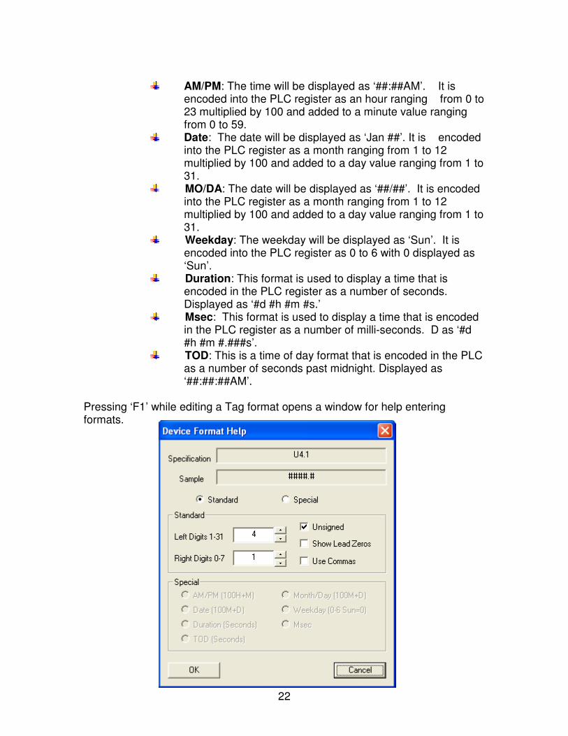
AM/PM: The time will be displayed as ‘##:##AM’. It is
encoded into the PLC register as an hour ranging from 0 to 23 multiplied by 100 and added to a minute value ranging from 0 to 59.
Date: The date will be displayed as ‘Jan ##’. It is encoded into the PLC register as a month ranging from 1 to 12 multiplied by 100 and added to a day value ranging from 1 to 31.
MO/DA: The date will be displayed as ‘##/##’. It is encoded into the PLC register as a month ranging from 1 to 12 multiplied by 100 and added to a day value ranging from 1 to 31.
Weekday: The weekday will be displayed as ‘Sun’. It is encoded into the PLC register as 0 to 6 with 0 displayed as ‘Sun’.
Duration: This format is used to display a time that is encoded in the PLC register as a number of seconds. Displayed as ‘#d #h #m #s.’
Msec: This format is used to display a time that is encoded in the PLC register as a number of milli-seconds. D as ‘#d #h #m #.###s’.
TOD: This is a time of day format that is encoded in the PLC as a number of seconds past midnight. Displayed as ‘##:##:##AM’.
Pressing ‘F1’ while editing a Tag format opens a window for help entering formats.
23
14. Alarms
There are several types of alarms in CorsairHMI. The simplest is the High Alarm function in a tag. To use it you set up a tag like TankHighAlarmIndicator. Make it an indicator, and assign it a High Alarm Block (F6 – Block – High Alarm - Accept – Parameters). This will provide a simple on-off indicator for an analog tag. CorsairHMI also has an extensive subsystem for handling alarms. This system includes acknowledge, latch and an alarm log. In order to use this system you use the 4-Bit Alarm Data Type. CorsairHMI allows the developer to set up alarms that the operator can see on the alarm summary window. The operator can acknowledge alarms and sometimes reset them. The developer can trip some alarms to see how the system responds to them. Corsair can be configured to send an email message when an alarm is tripped, when it is acknowledged, or when it is reset. An ‘Alarm‘ is one type of Corsair database record. There is another type of record that is a ‘Call’. Calls are nearly identical to alarms. Calls cannot initiate email messages. Calls can be reset without being acknowledged first. Calls appear after alarms on the Alarm Summary window. Most references to ‘Alarms’ in the rest of this document also apply to Calls. When an alarm is first tripped it appears flashing on the alarm summary window. Flashing indicates an ‘Unacknowledged’ alarm. When the operator acknowledges it the line on the window stops flashing. When the alarm condition is reset the alarm disappears from the summary window. Alarm Options Some alarms can self-reset when the alarm condition clears. A tank high level alarm may reset itself when the level goes below the high level alarm setpoint. Other alarms may require a reset action by the Corsair operator. A common example is a motor failure alarm that indicates that a motor did not start. A plc may try to start the motor and look for a starter contact to confirm that the motor is running. If the PLC does not get this contact within a short time it would activate the motor failure alarm and shut off the output that runs the motor. In most cases the alarm should stay active until the operator resets the alarm and the PLC tries to start the motor again. The ‘Operator Reset’ Yes/No option on the Corsair alarm record is used by the developer to define how the alarm is going to act. Another alarm option is related to what happens when an alarm has cleared itself before it is acknowledged by the operator. Some alarms may be cleared from the summary page before acknowledgement occurs. Other alarms should stay
24
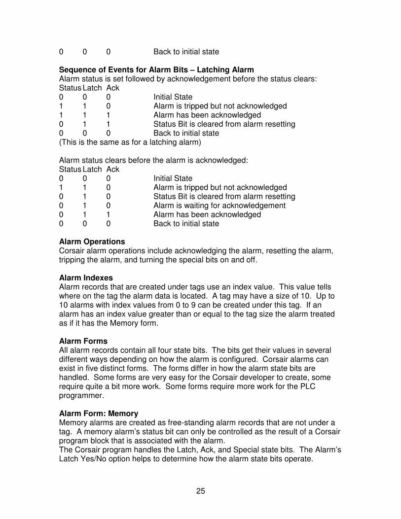
on the summary page until they are acknowledged to make sure that the operator knows that the alarm occurred. The “Latch’ Yes/No option on the Corsair alarm record is used by the developer to define this behavior for some forms of alarm. Alarm State Bits Each alarm database record has 4 state bits that are kept within the alarm record itself. These bits are designated as follows: Status – Bit 0 – least significant Latch – Bit 1 Acknowledge (‘Ack’) - Bit 2 Special – Bit 3 – most significant The Corsair Alarm Summary window looks at three of these bits – Status, Latch, and Ack. They have predefined meanings to the Corsair program. The fourth Special bit does not have any special significance to Corsair. The Status bit corresponds to the state of the alarm. It is one when the alarm is active and zero when it is not active. A simple high level alarm on a water tank may have a setpoint of 12 feet. When the level is 13 feet the alarm status bit would be ‘On’ (1). When the level is 11 feet the alarm status bit would be ‘Off’ (0). The Ack bit is turned on when the Corsair operator acknowledges the alarm. It is used to indicate that the operator saw the alarm. Some systems may use this bit to silence some sort of audible device like a bell or buzzer. ‘Silencing’ an alarm is not the same thing as ‘Resetting’ an alarm. The Latch bit is used to ‘remember’ that the alarm status bit has been on when the status has been cleared before the alarm is acknowledged. Sequence of Events for Alarm Bits – Non-Latching Alarm Alarm status is set followed by acknowledgement before the status clears: Status Latch Ack 0 0 0 Initial State 1 1 0 Alarm is tripped but not acknowledged 1 1 1 Alarm has been acknowledged 0 1 1 Status Bit is cleared from alarm resetting 0 0 0 Back to initial state Alarm status clears before the alarm is acknowledged: Status Latch Ack 0 0 0 Initial State 1 1 0 Alarm is tripped but not acknowledged 0 1 0 Status Bit is cleared from alarm resetting
25
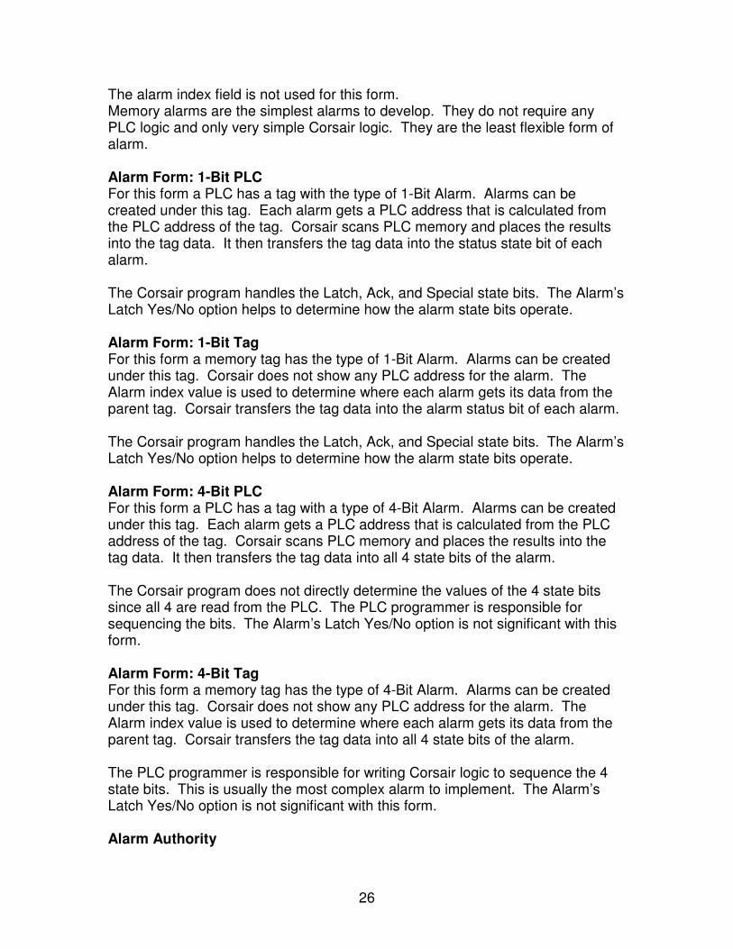
0 0 0 Back to initial state Sequence of Events for Alarm Bits – Latching Alarm Alarm status is set followed by acknowledgement before the status clears: Status Latch Ack 0 0 0 Initial State 1 1 0 Alarm is tripped but not acknowledged 1 1 1 Alarm has been acknowledged 0 1 1 Status Bit is cleared from alarm resetting 0 0 0 Back to initial state (This is the same as for a latching alarm) Alarm status clears before the alarm is acknowledged: Status Latch Ack 0 0 0 Initial State 1 1 0 Alarm is tripped but not acknowledged 0 1 0 Status Bit is cleared from alarm resetting 0 1 0 Alarm is waiting for acknowledgement 0 1 1 Alarm has been acknowledged 0 0 0 Back to initial state Alarm Operations Corsair alarm operations include acknowledging the alarm, resetting the alarm, tripping the alarm, and turning the special bits on and off. Alarm Indexes Alarm records that are created under tags use an index value. This value tells where on the tag the alarm data is located. A tag may have a size of 10. Up to 10 alarms with index values from 0 to 9 can be created under this tag. If an alarm has an index value greater than or equal to the tag size the alarm treated as if it has the Memory form. Alarm Forms All alarm records contain all four state bits. The bits get their values in several different ways depending on how the alarm is configured. Corsair alarms can exist in five distinct forms. The forms differ in how the alarm state bits are handled. Some forms are very easy for the Corsair developer to create, some require quite a bit more work. Some forms require more work for the PLC programmer. Alarm Form: Memory Memory alarms are created as free-standing alarm records that are not under a tag. A memory alarm’s status bit can only be controlled as the result of a Corsair program block that is associated with the alarm. The Corsair program handles the Latch, Ack, and Special state bits. The Alarm’s Latch Yes/No option helps to determine how the alarm state bits operate.
26
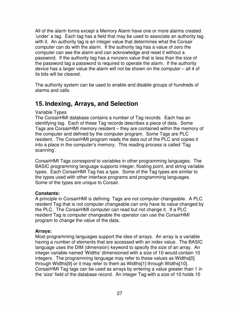
The alarm index field is not used for this form. Memory alarms are the simplest alarms to develop. They do not require any PLC logic and only very simple Corsair logic. They are the least flexible form of alarm. Alarm Form: 1-Bit PLC For this form a PLC has a tag with the type of 1-Bit Alarm. Alarms can be created under this tag. Each alarm gets a PLC address that is calculated from the PLC address of the tag. Corsair scans PLC memory and places the results into the tag data. It then transfers the tag data into the status state bit of each alarm. The Corsair program handles the Latch, Ack, and Special state bits. The Alarm’s Latch Yes/No option helps to determine how the alarm state bits operate. Alarm Form: 1-Bit Tag For this form a memory tag has the type of 1-Bit Alarm. Alarms can be created under this tag. Corsair does not show any PLC address for the alarm. The Alarm index value is used to determine where each alarm gets its data from the parent tag. Corsair transfers the tag data into the alarm status bit of each alarm. The Corsair program handles the Latch, Ack, and Special state bits. The Alarm’s Latch Yes/No option helps to determine how the alarm state bits operate. Alarm Form: 4-Bit PLC For this form a PLC has a tag with a type of 4-Bit Alarm. Alarms can be created under this tag. Each alarm gets a PLC address that is calculated from the PLC address of the tag. Corsair scans PLC memory and places the results into the tag data. It then transfers the tag data into all 4 state bits of the alarm. The Corsair program does not directly determine the values of the 4 state bits since all 4 are read from the PLC. The PLC programmer is responsible for sequencing the bits. The Alarm’s Latch Yes/No option is not significant with this form. Alarm Form: 4-Bit Tag For this form a memory tag has the type of 4-Bit Alarm. Alarms can be created under this tag. Corsair does not show any PLC address for the alarm. The Alarm index value is used to determine where each alarm gets its data from the parent tag. Corsair transfers the tag data into all 4 state bits of the alarm. The PLC programmer is responsible for writing Corsair logic to sequence the 4 state bits. This is usually the most complex alarm to implement. The Alarm’s Latch Yes/No option is not significant with this form. Alarm Authority
27
All of the alarm forms except a Memory Alarm have one or more alarms created ‘under’ a tag. Each tag has a field that may be used to associate an authority tag with it. An authority tag is an integer value that determines what the Corsair computer can do with the alarm. If the authority tag has a value of zero the computer can see the alarm and can acknowledge and reset it without a password. If the authority tag has a nonzero value that is less than the size of the password tag a password is required to operate the alarm. If the authority device has a larger value the alarm will not be shown on the computer – all 4 of its bits will be cleared. The authority system can be used to enable and disable groups of hundreds of alarms and calls.
15. Indexing, Arrays, and Selection
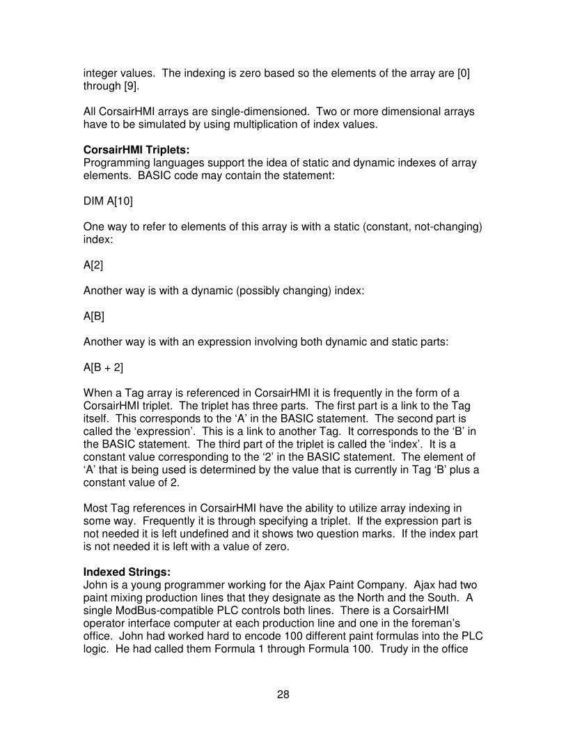
Variable Types The CorsairHMI database contains a number of Tag records. Each has an identifying tag. Each of these Tag records describes a piece of data. Some Tags are CorsairHMI memory resident – they are contained within the memory of the computer and defined by the computer program. Some Tags are PLC resident. The CorsairHMI program reads the data out of the PLC and copies it into a place in the computer’s memory. This reading process is called ‘Tag scanning’. CorsairHMI Tags correspond to variables in other programming languages. The BASIC programming language supports integer, floating point, and string variable types. Each CorsairHMI Tag has a type. Some of the Tag types are similar to the types used with other interface programs and programming languages. Some of the types are unique to Corsair. Constants: A principle in CorsairHMI is defining Tags are not computer changeable. A PLC resident Tag that is not computer changeable can only have its value changed by the PLC. The CorsairHMI computer can read but not change it. If a PLC resident Tag is computer changeable the operator can use the CorsairHMI program to change the value of the data. Arrays: Most programming languages support the idea of arrays. An array is a variable having a number of elements that are accessed with an index value. The BASIC language uses the DIM (dimension) keyword to specify the size of an array. An integer variable named ‘Widths’ dimensioned with a size of 10 would contain 10 integers. The programming language may refer to these values as Widths[0] through Widths[9] or it may refer to them as Widths[1] through Widths[10]. CorsairHMI Tag tags can be used as arrays by entering a value greater than 1 in the ‘size’ field of the database record. An integer Tag with a size of 10 holds 10
28
integer values. The indexing is zero based so the elements of the array are [0] through [9]. All CorsairHMI arrays are single-dimensioned. Two or more dimensional arrays have to be simulated by using multiplication of index values. CorsairHMI Triplets: Programming languages support the idea of static and dynamic indexes of array elements. BASIC code may contain the statement: DIM A[10] One way to refer to elements of this array is with a static (constant, not-changing) index: A[2] Another way is with a dynamic (possibly changing) index: A[B] Another way is with an expression involving both dynamic and static parts: A[B + 2] When a Tag array is referenced in CorsairHMI it is frequently in the form of a CorsairHMI triplet. The triplet has three parts. The first part is a link to the Tag itself. This corresponds to the ‘A’ in the BASIC statement. The second part is called the ‘expression’. This is a link to another Tag. It corresponds to the ‘B’ in the BASIC statement. The third part of the triplet is called the ‘index’. It is a constant value corresponding to the ‘2’ in the BASIC statement. The element of ‘A’ that is being used is determined by the value that is currently in Tag ‘B’ plus a constant value of 2. Most Tag references in CorsairHMI have the ability to utilize array indexing in some way. Frequently it is through specifying a triplet. If the expression part is not needed it is left undefined and it shows two question marks. If the index part is not needed it is left with a value of zero. Indexed Strings: John is a young programmer working for the Ajax Paint Company. Ajax had two paint mixing production lines that they designate as the North and the South. A single ModBus-compatible PLC controls both lines. There is a CorsairHMI operator interface computer at each production line and one in the foreman’s office. John had worked hard to encode 100 different paint formulas into the PLC logic. He had called them Formula 1 through Formula 100. Trudy in the office
29
has word-processed a list of what color of paint corresponds to each formula number. Copies of this list have been given to all the operators and the foremen. John set up two Tag records in the CorsairHMI database. They are computer-changeable integers with a format of U3. The first is tagged ‘North Product Index’. It is located at register 400001. The second is tagged ‘South Product Index’ located at register 400002. The operators were instructed to type in the proper number (1-100) for the paint that they are making each morning. At night before the last shift leaves they were to enter a Zero to make sure that the line shuts off and cannot be started until someone enters a valid formula number. The foremen could see what formula is running each day from the CorsairHMI interface in their office. The line started up and ran well but the foremen complained of having to look at the list to see if the proper formula number was running each day. CorsairHMI enumerations were not a good choice for this application. John investigated CorsairHMI string Tag types. He created a CorsairHMI memory-resident Tag named ‘Formula Names’. He gave it a length of 10 characters and an array size of 101. He used the Tag data monitor to type the names of the paint formulas into each index of the string array. For index 0 he entered the value ‘Off’. 1 was Red, 2 was Green, 3 was Blue, and so on. The CorsairHMI database had two screens in it, one for the North line and one for the South. Each screen had a place to enter the Product index for that line. Next to the place where the number was entered John put a value placement. The value tag was ‘Formula Names’. The expression tag was “North Product Index’. The placement was then transported to the south screen and the expression tag on that screen was changed to ‘South Product Index’. John copied the CorsairHMI CAP file to all three interfaces. Now whenever a line ran Blue the number 3 was on the screen and the word ‘Blue’ was next to it. This made the foremen happy since they didn’t need the printed list anymore and it helped to avoid errors. The foremen were happier than John since the line ran so well that business increased and they started to run more types of colors. Every time that the list of formula names changed Trudy would print out the new list. John would have to enter the names into CorsairHMI and then copy the CAP file to each of the interface computers. John got a great idea. He realized that his PLC had lots of extra register memory. If he kept the paint names in PLC registers each interface could see the names without changing the CAP file. He moved the ‘Formula Names’ string Tag to the PLC and started it at address 400003. The CorsairHMI program calculated the end address for him. Now John wanted to do two things. The first thing was to lock in the string “Off” at index zero so that nobody could change it. He wasn’t familiar with ASCII
30
codes but he used the CorsairHMI ASCII expert to figure out decimal equivalents of the letters that he wanted to use for the name. He set up a section of his PLC program to execute once every ten seconds. He put MOVE commands in this section to load the PLC registers with the proper decimal values to put “Off” in the first index of the string. The next thing that John wanted to do was help to guarantee that nobody would ever use the string Tags PLC registers for another purpose. He wasn’t concerned about doing this himself since he never wrote PLC program code without his CorsairHMI Tree print-out but another programmer might cause a problem. He put another instruction in the 10-second routine. This was a long block move that started at register 400003 with a length sufficient to cover the whole ASCII string space. The destination of the move was register 400003. This instruction didn’t really change anything since it copied the values to the same place that they came from. The thing that it did accomplish is that someone searching for uses of any of the registers in this block using the PLC programming software would find the block. It served as documentation that the registers were used. John could now enter new paint formula names from any CorsairHMI interface using the CorsairHMI Tag data monitor and the names would appear on all the other interfaces instantly. He became concerned about the security of the data so he set up a CorsairHMI authority Tag so that only the foremen could enter formula name data. The Tag data monitor wasn’t the easiest way for the foremen to work. John now realized that the names could be entered through a CorsairHMI sheet. The sheet had two columns. The left column contained constants from 1 through 100. The right column had enterable paint names. Now it was much more natural for the foremen to enter the data. Another benefit was that anyone with a CorsairHMI computer could print out the color name list any time that they want to. The next step was that Trudy was given a (legal) copy of the CorsairHMI program to run on the computer on her desk. She now entered the color names into PLC memory and printed the list from the CorsairHMI sheet. The operators got this printed list to work from. Selection: The foremen were now happy since they didn’t need the printed list but the operators still needed it. They had to know what number to type into the computer each morning for that day’s color. Sometimes Trudy would forget to print new copies of the list and frequently the lists would get lost or covered with paint. John started to study how CorsairHMI selectors work. A selector has an integer tag coupled with an array of strings. The operator types in what he wants. The
31
CorsairHMI program finds the closest string to what the operator has typed and enters the corresponding index value into the integer tag. If the operator typed ‘Green’ the computer put a 2 into the register. If he typed ‘Blue’ the computer put a 3 into the register. This was a perfect match for John’s application. The operators would type in a formula name as best they knew it and the computer would find and enter the formula number value for them. They didn’t need the printed list anymore. John has now figured out how to use bit-field Tag data types to encode formula data. Ajax has 27 computers legally running CorsairHMI software. John is now a vice-president. Trudy quit Ajax to marry him and they are now expecting their third child.
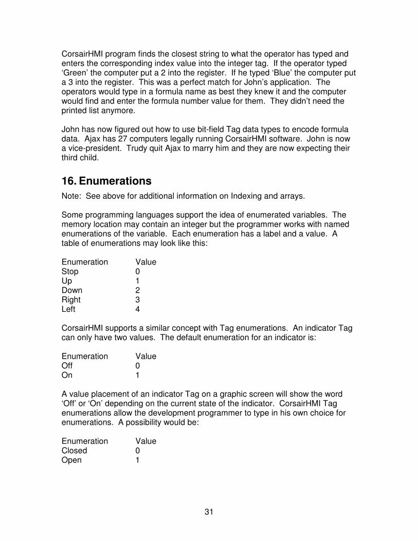
16. Enumerations
Note: See above for additional information on Indexing and arrays. Some programming languages support the idea of enumerated variables. The memory location may contain an integer but the programmer works with named enumerations of the variable. Each enumeration has a label and a value. A table of enumerations may look like this: Enumeration Value Stop 0 Up 1 Down 2 Right 3 Left 4 CorsairHMI supports a similar concept with Tag enumerations. An indicator Tag can only have two values. The default enumeration for an indicator is: Enumeration Value Off 0 On 1 A value placement of an indicator Tag on a graphic screen will show the word ‘Off’ or ‘On’ depending on the current state of the indicator. CorsairHMI Tag enumerations allow the development programmer to type in his own choice for enumerations. A possibility would be: Enumeration Value Closed 0 Open 1
32
This allows for the information on a display to more closely match wording that an operator is familiar with.
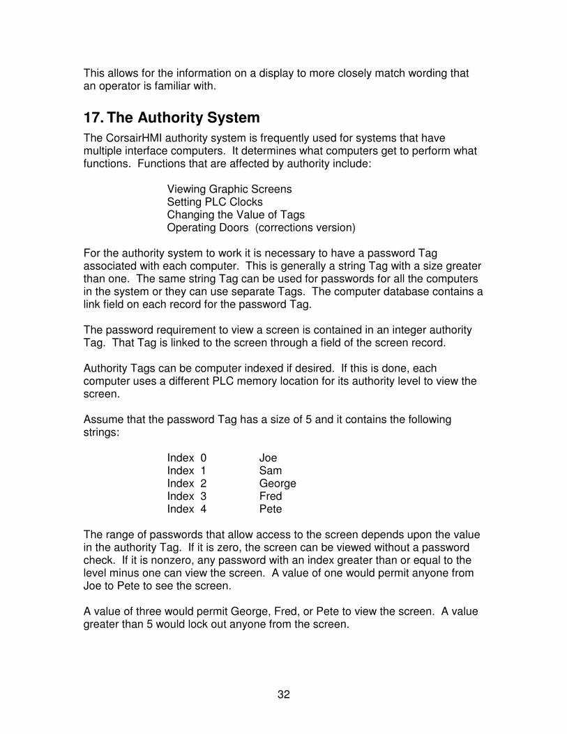
17. The Authority System
The CorsairHMI authority system is frequently used for systems that have multiple interface computers. It determines what computers get to perform what functions. Functions that are affected by authority include: Viewing Graphic Screens Setting PLC Clocks Changing the Value of Tags Operating Doors (corrections version) For the authority system to work it is necessary to have a password Tag associated with each computer. This is generally a string Tag with a size greater than one. The same string Tag can be used for passwords for all the computers in the system or they can use separate Tags. The computer database contains a link field on each record for the password Tag. The password requirement to view a screen is contained in an integer authority Tag. That Tag is linked to the screen through a field of the screen record. Authority Tags can be computer indexed if desired. If this is done, each computer uses a different PLC memory location for its authority level to view the screen. Assume that the password Tag has a size of 5 and it contains the following strings: Index 0 Joe Index 1 Sam Index 2 George Index 3 Fred Index 4 Pete The range of passwords that allow access to the screen depends upon the value in the authority Tag. If it is zero, the screen can be viewed without a password check. If it is nonzero, any password with an index greater than or equal to the level minus one can view the screen. A value of one would permit anyone from Joe to Pete to see the screen. A value of three would permit George, Fred, or Pete to view the screen. A value greater than 5 would lock out anyone from the screen.
33
Authority levels can be changed from PLC logic if authority Tags are located in PLC memory.
18. Hook Codes
During interface operation the operator may ‘hook’ to different placements on the screen by touching the surface of a touch monitor or by clicking the mouse. Many types of placements can be hooked without being operated. When they are hooked the status window displays data pertaining to the placement. Corrections applications frequently require that the PLC has some knowledge of what placement the operator is hooked to. An example is when door control, closed circuit TV, and intercom are all integrated. When the operator touches the placement corresponding to a cell door the video switcher should show him a view of the door and the intercom should be ready to talk to the speaker inside that cell. This is accomplished through the use of one or more hook code values that can be associated with each screen placement. The computer database has a record for each interface computer mode that is running the application. It provides fields that may be used to link each computer up to three hook code Tags. These Tags are used to specify what PLC data addresses receive the hook code values when the operator hooks a placement. For example, an integer Tag tagged ‘Camera #’ could be placed on a PLC. Another named ‘Intercom Station’ could be placed on the same or a different PLC. The first hook code Tag for a computer would then be set to ‘Camera #’ and the second to ‘Intercom Station.’ Camera numbers for a video switcher could range from 1 to 16. Intercom station numbers could be 3-digit values from 100 to 999. As each hookable placement is put on the screen it would have a camera number entered into the first hook code value and an intercom station number entered into the second hook code value. The PLC would then control the video switcher and the intercom so that they would track with the actions of the operator. The PLC-based hook code approach to integration tends to work more efficiently than direct computer control of video and intercom when there are multiple computer interface nodes. Typically each interface computer uses different addresses for its hook code Tags. They may be created as separate tags. A common alternative is to utilize computer indexing on the hook code Tags. This permits using the same Tag for hook codes on all computers in the database as long as each computer has a unique addressing index. The computer writes the hook value(s) into the appropriate Tags one time when the placement is hooked and the hook code values are non-zero. It writes zeros one time when the placement is unhooked. Changing directly from one
34
placement to another that has non-zero hook codes will cause the new values to be written without a zero value between them.
19. The Splash Screen
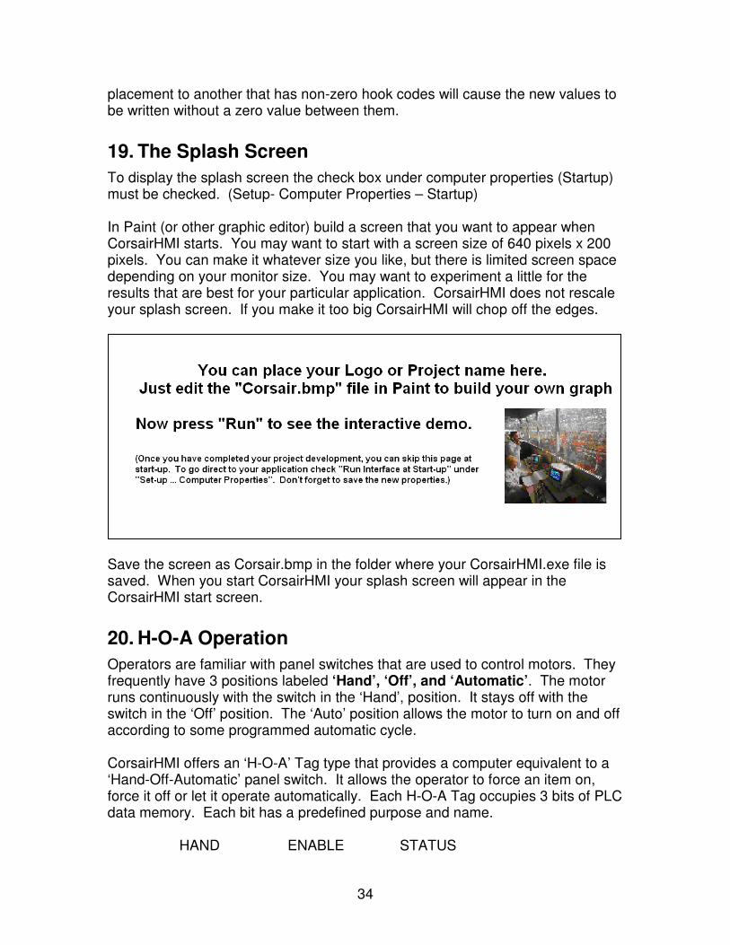
To display the splash screen the check box under computer properties (Startup) must be checked. (Setup- Computer Properties – Startup) In Paint (or other graphic editor) build a screen that you want to appear when CorsairHMI starts. You may want to start with a screen size of 640 pixels x 200 pixels. You can make it whatever size you like, but there is limited screen space depending on your monitor size. You may want to experiment a little for the results that are best for your particular application. CorsairHMI does not rescale your splash screen. If you make it too big CorsairHMI will chop off the edges.
Save the screen as Corsair.bmp in the folder where your CorsairHMI.exe file is saved. When you start CorsairHMI your splash screen will appear in the CorsairHMI start screen.
20. H-O-A Operation
Operators are familiar with panel switches that are used to control motors. They frequently have 3 positions labeled ‘Hand’, ‘Off’, and ‘Automatic’. The motor runs continuously with the switch in the ‘Hand’, position. It stays off with the switch in the ‘Off’ position. The ‘Auto’ position allows the motor to turn on and off according to some programmed automatic cycle. CorsairHMI offers an ‘H-O-A’ Tag type that provides a computer equivalent to a ‘Hand-Off-Automatic’ panel switch. It allows the operator to force an item on, force it off or let it operate automatically. Each H-O-A Tag occupies 3 bits of PLC data memory. Each bit has a predefined purpose and name. HAND ENABLE STATUS
35
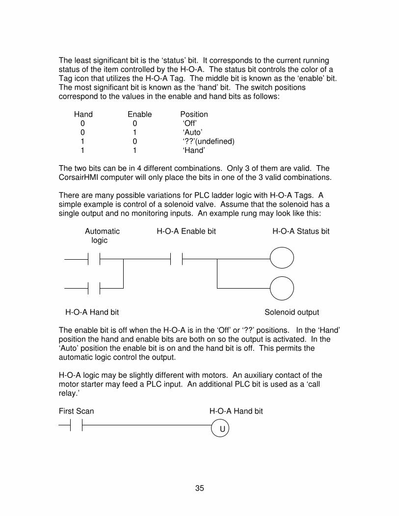
The least significant bit is the ‘status’ bit. It corresponds to the current running status of the item controlled by the H-O-A. The status bit controls the color of a Tag icon that utilizes the H-O-A Tag. The middle bit is known as the ‘enable’ bit. The most significant bit is known as the ‘hand’ bit. The switch positions correspond to the values in the enable and hand bits as follows: Hand Enable Position 0 0 ‘Off’ 0 1 ‘Auto’ 1 0 ‘??’(undefined) 1 1 ‘Hand’ The two bits can be in 4 different combinations. Only 3 of them are valid. The CorsairHMI computer will only place the bits in one of the 3 valid combinations. There are many possible variations for PLC ladder logic with H-O-A Tags. A simple example is control of a solenoid valve. Assume that the solenoid has a single output and no monitoring inputs. An example rung may look like this: Automatic H-O-A Enable bit H-O-A Status bit logic H-O-A Hand bit Solenoid output The enable bit is off when the H-O-A is in the ‘Off’ or ‘??’ positions. In the ‘Hand’ position the hand and enable bits are both on so the output is activated. In the ‘Auto’ position the enable bit is on and the hand bit is off. This permits the automatic logic control the output. H-O-A logic may be slightly different with motors. An auxiliary contact of the motor starter may feed a PLC input. An additional PLC bit is used as a ‘call relay.’ First Scan H-O-A Hand bit U
36
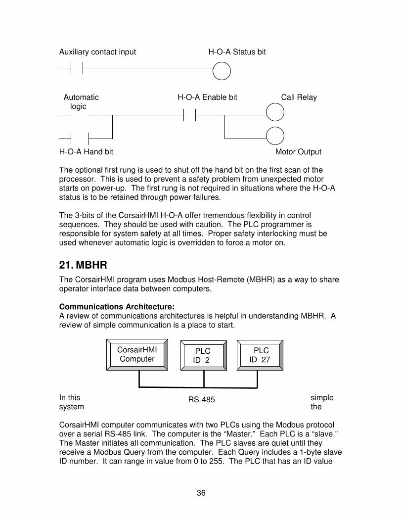
Auxiliary contact input H-O-A Status bit Automatic H-O-A Enable bit Call Relay logic H-O-A Hand bit Motor Output The optional first rung is used to shut off the hand bit on the first scan of the processor. This is used to prevent a safety problem from unexpected motor starts on power-up. The first rung is not required in situations where the H-O-A status is to be retained through power failures. The 3-bits of the CorsairHMI H-O-A offer tremendous flexibility in control sequences. They should be used with caution. The PLC programmer is responsible for system safety at all times. Proper safety interlocking must be used whenever automatic logic is overridden to force a motor on.
21. MBHR
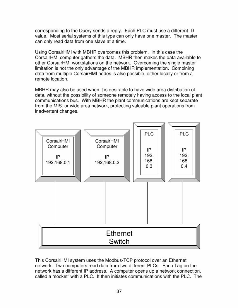
The CorsairHMI program uses Modbus Host-Remote (MBHR) as a way to share operator interface data between computers. Communications Architecture: A review of communications architectures is helpful in understanding MBHR. A review of simple communication is a place to start. In this simple system the
CorsairHMI computer communicates with two PLCs using the Modbus protocol over a serial RS-485 link. The computer is the “Master.” Each PLC is a “slave.” The Master initiates all communication. The PLC slaves are quiet until they receive a Modbus Query from the computer. Each Query includes a 1-byte slave ID number. It can range in value from 0 to 255. The PLC that has an ID value
CorsairHMI Computer
PLC ID 2
PLC ID 27
RS-485
37
corresponding to the Query sends a reply. Each PLC must use a different ID value. Most serial systems of this type can only have one master. The master can only read data from one slave at a time. Using CorsairHMI with MBHR overcomes this problem. In this case the CorsairHMI computer gathers the data. MBHR then makes the data available to other CorsairHMI workstations on the network. Overcoming the single master limitation is not the only advantage of the MBHR implementation. Combining data from multiple CorsairHMI nodes is also possible, either locally or from a remote location. MBHR may also be used when it is desirable to have wide area distribution of data, without the possibility of someone remotely having access to the local plant communications bus. With MBHR the plant communications are kept separate from the MIS or wide area network, protecting valuable plant operations from inadvertent changes.
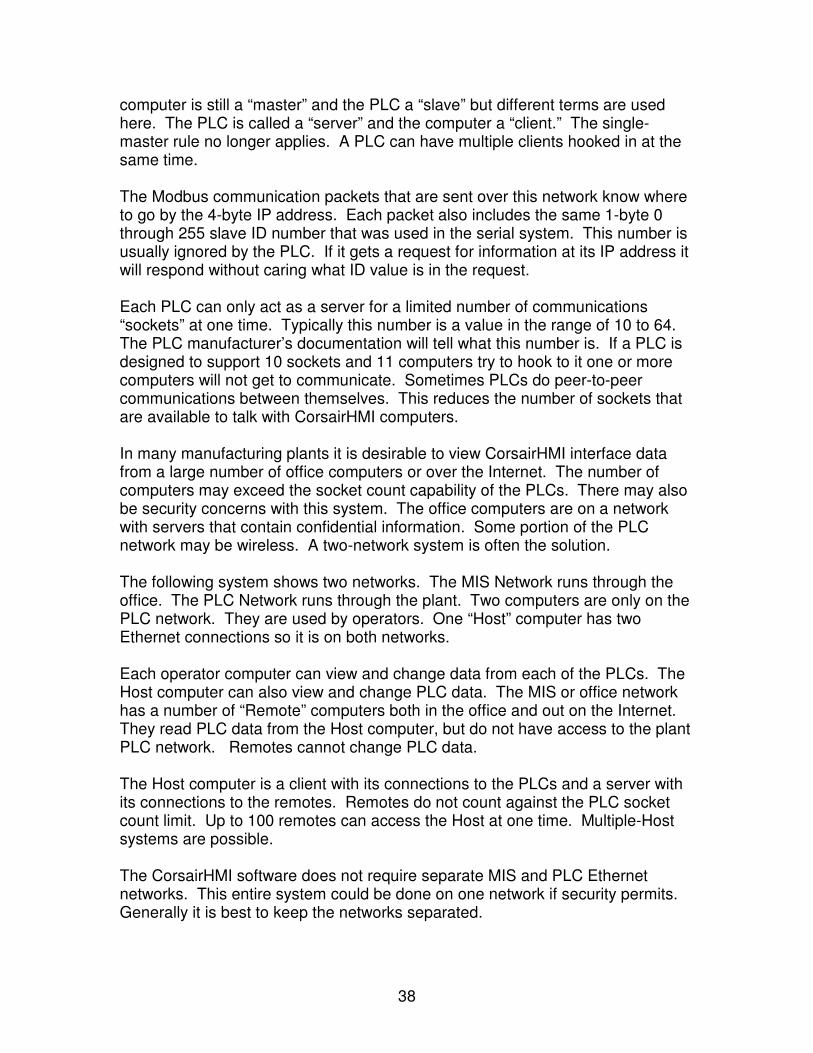
This CorsairHMI system uses the Modbus-TCP protocol over an Ethernet network. Two computers read data from two different PLCs. Each Tag on the network has a different IP address. A computer opens up a network connection, called a “socket” with a PLC. It then initiates communications with the PLC. The
CorsairHMI Computer
IP
192.168.0.1
CorsairHMI Computer
IP
192,168.0.2
PLC
IP 192. 168. 0.3
PLC
IP 192. 168. 0.4
Ethernet Switch
38
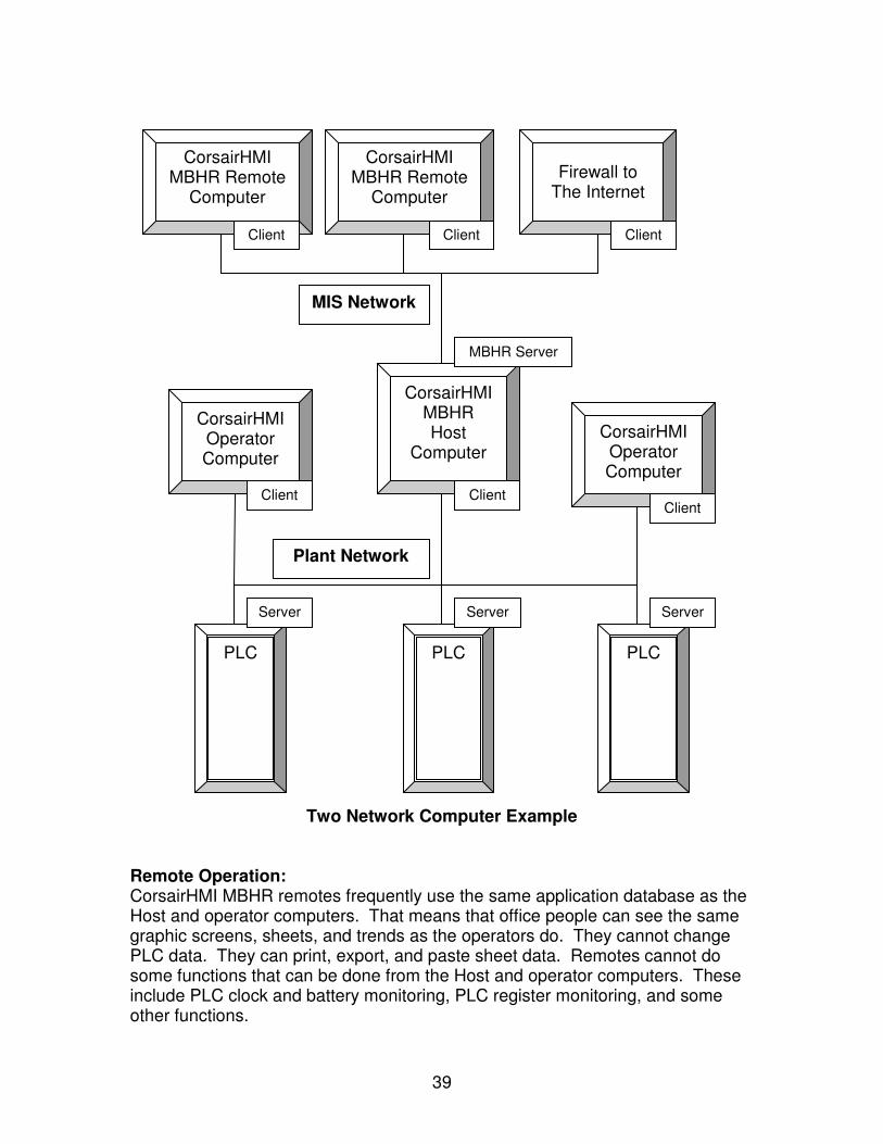
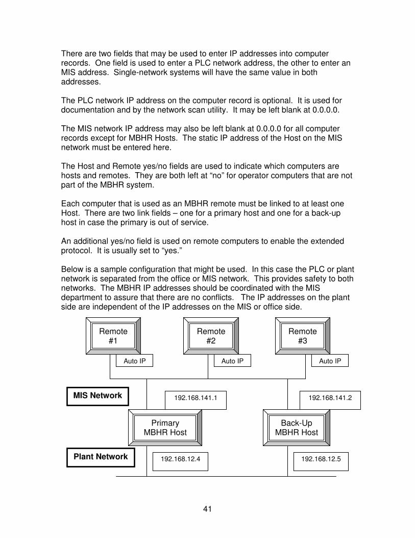
computer is still a “master” and the PLC a “slave” but different terms are used here. The PLC is called a “server” and the computer a “client.” The single-master rule no longer applies. A PLC can have multiple clients hooked in at the same time. The Modbus communication packets that are sent over this network know where to go by the 4-byte IP address. Each packet also includes the same 1-byte 0 through 255 slave ID number that was used in the serial system. This number is usually ignored by the PLC. If it gets a request for information at its IP address it will respond without caring what ID value is in the request. Each PLC can only act as a server for a limited number of communications “sockets” at one time. Typically this number is a value in the range of 10 to 64. The PLC manufacturer’s documentation will tell what this number is. If a PLC is designed to support 10 sockets and 11 computers try to hook to it one or more computers will not get to communicate. Sometimes PLCs do peer-to-peer communications between themselves. This reduces the number of sockets that are available to talk with CorsairHMI computers. In many manufacturing plants it is desirable to view CorsairHMI interface data from a large number of office computers or over the Internet. The number of computers may exceed the socket count capability of the PLCs. There may also be security concerns with this system. The office computers are on a network with servers that contain confidential information. Some portion of the PLC network may be wireless. A two-network system is often the solution. The following system shows two networks. The MIS Network runs through the office. The PLC Network runs through the plant. Two computers are only on the PLC network. They are used by operators. One “Host” computer has two Ethernet connections so it is on both networks. Each operator computer can view and change data from each of the PLCs. The Host computer can also view and change PLC data. The MIS or office network has a number of “Remote” computers both in the office and out on the Internet. They read PLC data from the Host computer, but do not have access to the plant PLC network. Remotes cannot change PLC data. The Host computer is a client with its connections to the PLCs and a server with its connections to the remotes. Remotes do not count against the PLC socket count limit. Up to 100 remotes can access the Host at one time. Multiple-Host systems are possible. The CorsairHMI software does not require separate MIS and PLC Ethernet networks. This entire system could be done on one network if security permits. Generally it is best to keep the networks separated.
39
Two Network Computer Example
Remote Operation: CorsairHMI MBHR remotes frequently use the same application database as the Host and operator computers. That means that office people can see the same graphic screens, sheets, and trends as the operators do. They cannot change PLC data. They can print, export, and paste sheet data. Remotes cannot do some functions that can be done from the Host and operator computers. These include PLC clock and battery monitoring, PLC register monitoring, and some other functions.
CorsairHMI MBHR Remote
Computer
CorsairHMI MBHR Remote
Computer
Client Client Client
MIS Network
MBHR Server
Client Client Client
Plant Network
Server Server Server
Firewall to The Internet
CorsairHMI Operator Computer
CorsairHMI MBHR Host
Computer CorsairHMI Operator Computer
PLC PLC PLC
40
IP Address Considerations: Because CorsairHMI connects to servers using fixed IP addresses the PLC addresses must be static. This means that the PLC always powers up with the same IP address. These addresses are entered into the CorsairHMI application database. CorsairHMI does not need to know client-side IP addresses. The two operator computers and the PLC network side of the Host computer could have automatic IP addresses sent out by an address server if desired. The address server must never assign IP addresses that conflict with the static PLC IP addresses. As a general rule all PLC network IP addresses are static. Most MIS office networks use automatically assigned IP addresses on all computers. This can be true of all the CorsairHMI remotes. The MIS network side of the CorsairHMI Host must have fixed IP address that is entered into the CorsairHMI database. The address server must properly allow for this. CorsairHMI Computer Database Setup: The CorsairHMI application database file contains a list of CorsairHMI computers. Usually every CorsairHMI computer that is part of the computer is listed in this database. Each computer record has a number of database fields. They include: Computer Name Computer ID PLC Network IP Address Host? Yes/No MIS network IP Address Remote? Yes/No MBHR Primary Host MBHR Back-Up Host Extended Protocol? Yes/No The computer name field is the CorsairHMI tag name for the computer. It can be anything that the CorsairHMI developer desires. Each tag name should be unique so that there are not duplicates in the list. Systems with a large number of remotes may only have one computer record to represent all of the remotes. Each CorsairHMI computer has a small computer properties file. This data is entered through the setup/computer properties menu option. The security tab contains a place to enter the CorsairHMI computer tag name of that computer. This name should match a tag name in the computer database. The Computer ID field may be used to enter the TCP/IP network name of each computer. This is an optional field that is used for documentation. It may be left blank.
41
There are two fields that may be used to enter IP addresses into computer records. One field is used to enter a PLC network address, the other to enter an MIS address. Single-network systems will have the same value in both addresses. The PLC network IP address on the computer record is optional. It is used for documentation and by the network scan utility. It may be left blank at 0.0.0.0. The MIS network IP address may also be left blank at 0.0.0.0 for all computer records except for MBHR Hosts. The static IP address of the Host on the MIS network must be entered here. The Host and Remote yes/no fields are used to indicate which computers are hosts and remotes. They are both left at “no” for operator computers that are not part of the MBHR system. Each computer that is used as an MBHR remote must be linked to at least one Host. There are two link fields – one for a primary host and one for a back-up host in case the primary is out of service. An additional yes/no field is used on remote computers to enable the extended protocol. It is usually set to “yes.” Below is a sample configuration that might be used. In this case the PLC or plant network is separated from the office or MIS network. This provides safety to both networks. The MBHR IP addresses should be coordinated with the MIS department to assure that there are no conflicts. The IP addresses on the plant side are independent of the IP addresses on the MIS or office side.
Auto IP Auto IP Auto IP
192.168.141.1 192.168.141.2
192.168.12.4 192.168.12.5
Remote #1
Remote #2
Remote #3
Primary MBHR Host
Back-Up MBHR Host
Plant Network
MIS Network
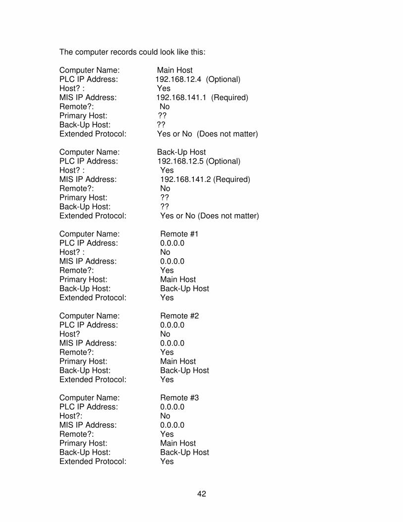
42
The computer records could look like this: Computer Name: Main Host PLC IP Address: 192.168.12.4 (Optional) Host? : Yes MIS IP Address: 192.168.141.1 (Required) Remote?: No Primary Host: ?? Back-Up Host: ?? Extended Protocol: Yes or No (Does not matter) Computer Name: Back-Up Host PLC IP Address: 192.168.12.5 (Optional) Host? : Yes MIS IP Address: 192.168.141.2 (Required) Remote?: No Primary Host: ?? Back-Up Host: ?? Extended Protocol: Yes or No (Does not matter) Computer Name: Remote #1 PLC IP Address: 0.0.0.0 Host? : No MIS IP Address: 0.0.0.0 Remote?: Yes Primary Host: Main Host Back-Up Host: Back-Up Host Extended Protocol: Yes Computer Name: Remote #2 PLC IP Address: 0.0.0.0 Host? No MIS IP Address: 0.0.0.0 Remote?: Yes Primary Host: Main Host Back-Up Host: Back-Up Host Extended Protocol: Yes Computer Name: Remote #3 PLC IP Address: 0.0.0.0 Host?: No MIS IP Address: 0.0.0.0 Remote?: Yes Primary Host: Main Host Back-Up Host: Back-Up Host Extended Protocol: Yes

43
Protocol Considerations: The communications protocol that is used between the CorsairHMI Host and Remote computers is the industry-standard Modbus TCP protocol. CorsairHMI could have defined a custom communications protocol for this purpose because it is for one CorsairHMI computer to talk to another. The advantage of a custom protocol would have been that it would have required less development work to make a host-remote database. Using Modbus for this function requires more development, but if offers huge advantages in flexibility and performance. The flexibility advantage of Modbus is because the CorsairHMI Host program can act as a Modbus server to other things besides CorsairHMI computers. A PLC or many other Modbus-compatible programs can read data from the CorsairHMI interface. The performance advantage of Modbus results from the ability to transfer data from multiple tags with single Modbus Query. There is no time-consuming tag name information transferred in the Modbus packet. The data is packed into an efficient raw binary format. CorsairHMI offers a proprietary extension to the Modbus protocol that may be used in MBHR systems between two CorsairHMI computers. The host can accept either conventional or extended Modbus Queries. The slave can use extended queries if the developer sets it up to use them. Extended replies can contain much more data than standard Modbus replies. This results in faster update speeds on remote computers. Minimal extra development work is required to use MBHR data, however when non-Modbus style addresses are used for data from the PLC, it is necessary to add a Modbus address. Assume that a host computer is talking to a PLC #5 reading an integer tag at address N7:2. The remote computer that wants to read this tag from the host cannot use “N7:2” since it isn’t a standard Modbus address. It needs an address like “400003.” There is a separate address field on each Tag record to enter a Modbus-compatible MBHR address. This is the address that is used by CorsairHMI for the Host to Remote data transfer. Although it may appear that the MBHR developer must enter and keep track of a totally separate list of MBHR addresses in addition to the PLC addresses, CorsairHMI contains tools to reduce or eliminate this work. Many PLCs use Modbus style addresses for the PLC to CorsairHMI communications. For these PLCs the MBHR address usually can be an exact copy of the PLC address. The Tools/Export/MBHR Addresses menu option has two options for this. The first copies Tag Modbus addresses from the Start
44
Address field to the MBHR address field. It overwrites any existing data in the MBHR address field. Another option performs the same copy without overwrites. The copy address generation options only work if the Tag is located on a PLC that uses Modbus style addresses. Another option causes CorsairHMI to automatically generate MBHR Modbus addresses for Tags that are not on Modbus PLCs. The Remote CorsairHMI Computer locates the Host CorsairHMI Computer using its IP address. It may read data from the host that is arranged under several PLCs. These PLCs are distinguished using a one-byte MBHR slave ID number that ranges from 1 to 255. These numbers can be entered into a PLC records “MBHR ID” field. They can also be generated automatically with Tools/Export/MBHR Addresses. Specialty MBHR Applications: Frequently the developer will want to use the same CorsairHMI application file for both the MBHR Host and Remote computers. CorsairHMI does not require this. Some systems may benefit from much faster performance if the Remote database is generated with optimized addresses. It is possible for an MBHR host to appear as one of several PLCs to another CorsairHMI computer that is not configured to act as a remote. A driver is included that permits the extended protocol to be used in these situations. A computer can act as both a host and remote to another computer that acts as both host and remote. Your CorsairHMI dealer can assist you in developing these sorts of specialty applications. It is also possible to use MBHR to simulate a remote PLC. This can be extremely useful in program development. Training can also be set up on a second CorsairHMI program so that an operator can be trained to react to conditions which might be created by the process. License Requirements: Each CorsairHMI program requires a license file to run. The contents of the license file are arranged between the customer and the CorsairHMI dealer. Some licenses support both MBHR host and remote operations from the same license file. Other customers may have separate license files for the Host and Remote computers. Minimal requirements for a Host computer license are: Database Computers: Must be > = 2 PLC Comms: Must be checked MBHR Host: Must be checked Minimal requirements for a Remote computer license are: Database computers: Must be >=2 MBHR Remote: Must be checked
45
A license that meets both of these requirements can be used on either a Host or Remote computer. An MBHR remote only license does not allow direct PLC communications. Some users have remote only licenses on office computers for security purposes. A CorsairHMI license may also be supplied which does not allow access to the development environment. This license is also available from CorsairHMI. Please contact CorsairHMI with your requirements.
22. Features:
• Redundancy And Distributed Inputs
• Versatile Tag Drivers Available Drivers include Modbus, AB, GE, ASCII, Maple, Siemens, CAL, West, Honeywell, Modicon, Nematron, Partlow and more
• Arrays Array blocks allow for faster programming and powerful math.
• Data Sharing o MBHR Modbus Host/Remote Interface provides data transfer to other Tags and
over the internet. It also allows the interchange of data with other programs on the same PC.
o VMI Vendor Managed Inventory provides dial up data to third parties for inventory or other requirements.
o ASCII Terminal Provides ASCII terminal output for remote information access.
• Remote Data/Graphics Display Provides remote computers with access to CorsairHMI data and graphics
• Unlimited Tags no practical limit (> 70,000) on the number of tags, either internal or external
• Data Transfer transfers data to files, remote computers, Excel compatible CSV files… on event, on time, on operator request.
23. Advanced Features:
• Quick Trends • Graphics High Resolution graphics provide an easy to use operator interface.
• Animation provides tank height, color change on alarm, invisible and other graphic conditional requirements.
• Sheets provide data display in a spreadsheet like format. Builds lists, reports, etc.
• Reports built in Sheets provide reports, load tickets, tracking, etc.
• Trends real time memory resident trends for easy data interpretation
• Datalog values on disc for future use, or easy review in Excel compatible CSV files
• Datalog Trends View Datalog files in trend mode directly from the CorsairHMI Interface
• Math mX+B, table look-up, max min, square root. A wide variety of mathematical functions in real time. Time arithmetic provides ramp and soak, integration capability
46
• Miniprograms String together blocks, make logical decisions in easy to use block scripting language
• Turn Back Time Easily view what happened in the past on your familiar graphic templates
• Alarm Management Print alarm logs, monitor alarm status, set software alarms. Alarm on unacknowledged alarms
• E-mail E-mails messages on alarm or other condition. Also can send messages to your cell phone or Fax (Coming soon). Contact CorsairHMI for details.
• Drawings Online drawings for use by electricians, maintenance and operators
• Print Manual Print I/O tree, blocks drawings etc for permanent reference.
24. Appendix I – Function Blocks
These were the blocks available at the time of this printing. New blocks are added frequently. For an updated list and description use the File-Print Function. Select the Nothing box, then check the About Blocks box under Corsair Program Reference. Absolute Value Block Purpose: Find Absolute Value This is a standard block. Version - 2.5 Build 52 Executed: Initialization Forward Reverse Environments: Tags PLC Results Alarms Calls Expressions Programs Array Results Finished Recipes Volatile Result Output Parameters: Result Result Absolute Value Result (Size PJ + PI) Parameter Label Type Format PA Enable Indicator PB ?? PC Input Value Array (Size PJ + PD) Double Float -12.5 PD Input Value Start Index Double Int U6.0 PE ?? PF ?? PG ?? PH ?? PI Result Array Start Index Double Int U6.0 PJ Count (>= 1) Double Int U6.0 This block is used to find the absolute value of each of the elements in an array and put it in a result array. This action is repeated for a total of PJ elements. Assume PD=2, PI=5, and PJ=3 PC[2]=-6 PC[3]=12 PC[4]=-2 When enabled the block will do the following: Result[5]=6 Result[6]=12 Result[7]=2
Addition Block Purpose: Add arrays based upon format This is a standard block. Version - 2.5 Build 52 Executed: Initialization Forward Reverse Environments: Tags PLC Results Alarms
47
Calls Expressions Programs Array Results Finished Recipes Volatile Result Output Parameters: Result Result Sum Array (Size PJ + PI) Parameter Label Type Format PA Enable Indicator PB ?? PC First Addend Array (Size PJ + PD) Double Float -12.5 PD First Addend Start Index Double Int U6.0 PE ?? PF Second Addend Array (Size PJ + PG) Double Float -12.5 PG Second Addend Start Index Double Int U6.0 PH ?? PI Sum Array Start Index Double Int U6.0 PJ Count (>= 1) Double Int U6.0 This block is used to add elements in the PC array to elements in the PF array and put the sum in the result array. The action is repeated for a total of PJ elements. Assume PD=2, PG=3, PI=4, and PJ=3 PC[2]=2.3 PC[3]=-4.6 PC[4]=23.2 PF[3]=1.5 PF[4]=2.7 PF[5]=12.8 When enabled the block will do the following: Result[4]=3.8 Result[5]=-1.9 Result[6]=36.0
ANSI Terminal Block Purpose: Drive an ANSI terminal through a serial port This is a standard block. Version - 2.5 Build 52 Executed: Initialization Forward Reverse Environments: Tags PLC Results Alarms Calls Expressions Programs Array Results Finished Recipes Volatile Result Output Parameters: Result Result Returned Error Code (Size 1) Parameter Label Type Format PA Row Array (Size <= 400) Integer U2.0 PB Column Array (size <= 400) Integer U2.0 PC String Array (Size <= 400) String PD Inverse Switches Array Switch PE Blink Switches Array Switch PF Disable Switches Array Switch PG Format Code Array Integer U5.0 PH Underline Switches Array Switch PI ?? PJ Clear Screen Trigger (Edge Detected) Indicator Variable Size Type Format Length Bytes BVA Transmitted Row 400 8-bit Field U2.0 400 BVB Transmitted Column 400 8-bit Field U2.0 400 BVC Transmitted Length 400 8-bit Field U2.0 400 BVD Port Number 1 8-bit Field U2.0 2
48
BVE Cursor On/Off 1 Switch 2 BVF Clear Screen Timing in Seconds 1 Double Int Duration 4 BVG Invert On/Off 1 Switch 2 Max bytes: 2000 Total bytes: 1210 This block is used for the CorsairHMI computer to drive a standard VT-100 ANSI-compatible text terminal through a serial port. The terminal is a display-only Tag. Corsair will ignore any keystrokes that come from the terminal. PA is an array of row positions ranging from 1 to 25 with 1 as the top of the terminal screen. PB is an array of column positions ranging from 1 to 80 with 1 as the left side of the screen. PC is an array of strings that are displayed at the PA and PB positions. Each string is inversed if the corresponding PD switch is on. Blink is controlled from PE and Underline from PH. Combinations of these attributes may be used. If the PF disable switch is on the string disappears from the screen. The PG format code array is used to control other aspects of the appearance of the string on the terminal display. These include justification and capitalization. The static (unchanging) labels that are to appear on the terminal screen are simply stored in the PC string array. Dynamic (changing) strings are copied into elements of this array using other program blocks. The String Copy block is designed to help with this function.
Array Distributor Block Purpose: Distribute values through an array This is a standard block. Version - 2.5 Build 52 Executed: Initialization Forward Reverse Environments: Tags PLC Results Alarms Calls Expressions Programs Array Results Finished Recipes Volatile Result Output Parameters: Result Result Values Distributed According to Code (Size PJ + PI) Parameter Label Type Format PA Enable Indicator PB ?? PC Code Array (Size PJ + PD) Integer U5.0 PD Code Start Index Double Int U6.0 PE ?? PF Code Value Array (Size PJ + PG) Double Float -12.5 PG Code Value Start Index Double Int U6.0 PH ?? PI Distributed Result Array Start Index Double Int U6.0 PJ Result Array Size Double Int U6.0 This block copies values from the PF code value array into elements of the result array. The distribution is controlled by codes in the PC array. Assume PD=3, PG=4, PI=5, and PJ=4 PC[3]=3 PC[4]=0 PC[5]=1 PC[6]=1 PF[4]=12.3 PF[5]=14.6 PF[6]=2.8 PF[7]=9.3 PF[8]=-2 When enabled, the block will do the following: Result[5]=9.3 [6]=12.3 [7]=14.6 [8]=14.6 Pseudo-Code: For(Loop=0; Loop<PJ; Loop++) Result[PI + Loop] = PF[PG + PC[PD + Loop]]
49
Array Element Selector Block Purpose: Switch between elements from two arrays This is a standard block. Version - 2.5 Build 52 Executed: Initialization Forward Reverse Environments: Tags PLC Results Alarms Calls Expressions Programs Array Results Finished Recipes Volatile Result Output Parameters: Result Result of the selection (Size PJ + PI) Parameter Label Type Format PA Enable Indicator PB Selector Switches Array Switch PC Selector Switches Start Index Double Int U6.0 PD Off Selection Array (Size PJ + PE) String PE Off Array Start Index Double Int U6.0 PF On Selection Array (Size PJ + PG) String PG On Array Start Index Double Int U6.0 PH ?? PI Result Array Start Index Double Int U6.0 PJ Count (>= 1) Double Int U6.0 This block is used to switch values in two input arrays into a third array. It does each element separately. If the PB input switch is Off the block copies a value from the PD Off array to the Result array. If the PB input switch is On the block copies a value from the PF On array to the result array. The action is done a total of PJ times. Assume PC=2, PE=3, PG=4, PI=5, PJ=4 PB[2]=Off PB[3]=On PB[4]=Off PB[5]=On PD[3]=2.3 PD[4]=3.7 PD[5]=12.2 PD[6]=8.2 PF[4]=1.5 PD[5]=5.9 PF[6]=6.3 PF[7]=16.4 When enabled the block will act as follows: Result[5]=2.3 [6]=5.9 [7]=12.2 [8]=16.4
Array Expansion Block Purpose: Expand a list of values This is a standard block. Version - 2.5 Build 52 Executed: Initialization Forward Reverse Environments: Tags PLC Results Alarms Calls Expressions Programs Array Results Finished Recipes Volatile Result Output Parameters: Result Result Expanded Array (Size PF * PJ + PI) Parameter Label Type Format PA Enable Indicator PB ?? PC Value Array (Size PJ + PD) String PD Value Array Start Index Double Int U6.0 PE ?? PF Number of expanded values per input (>= 1) Double Int U6.0 PG ?? PH ?? PI Result Array Start Index Double Int U6.0
50
PJ How many input values to expand (>= 1) Double Int U6.0 This block is used to copy each of PJ elements of a source array into PF elements of a destination array. Assume PD=7, PF=4, PI=2, PJ=5 PC[7]=8 PC[8]=5 PC[9]=7 PC[10]=9 PC[11]=2 When enabled the block will do the following Result[2]=8 Result[3]=8 Result[4]=8 Result[5]=8 Result[6]=5 Result[7]=5 Result[8]=5 Result[9]=5 Result[10]=7 Result[11]=7 Result[12]=7 Result[13]=7 Result[14]=9 Result[15]=9 Result[16]=9 Result[17]=9 Result[18]=2 Result[19]=2 Result[20]=2 Result[21]=2
Array Fill Block Purpose: Load an array of values from a single value This is a standard block. Version - 2.5 Build 52 Executed: Initialization Forward Reverse Environments: Tags PLC Results Alarms Calls Expressions Programs Array Results Finished Recipes Volatile Result Output Parameters: Result Result Array (Size PJ + PI) Parameter Label Type Format PA Enable Indicator PB ?? PC Source Value (Size PD + 1) String PD Source Index (only 1 element is used) Double Int U6.0 PE ?? PF ?? PG ?? PH ?? PI Result Array Start Index Double Int U6.0 PJ Count (>= 1) Double Int U6.0 This block is used to fill PJ values in the result array with the single source value that is at PC[PD]. Assume PD=3, PI=2, PJ=6, and PC[3]=12 PC[0]=9 PC[1]=10 PC[2]=11 PC[3]=12 PC[4]=13 When enabled the block will do the following: Result[2]=12 Result[3]=12 Result[4]=12 Result[5]=12 Result[6]=12 Result[7]=12
Array Maximum Block Purpose: Find the maximum of the elements in an array This is a standard block. Version - 2.5 Build 52 Executed: Initialization Forward Reverse Environments: Tags PLC Results Alarms Calls Expressions Programs Array Results Finished Recipes Volatile Result Output Parameters: PG Result Result Maximum (Size PI + 1) Parameter Label Type Format PA Enable Indicator
51
PB ?? PC Value Array String PD Value Array Start Index Double Int U6.0 PE ?? PF ?? PG Index to Maximum Element Double Int U6.0 PH ?? PI Result Index Double Int U6.0 PJ Value Array Element Count Double Int U6.0 Output Parameter P? is set to point to the maximum element Future - Discuss strings
Array Minimum Block Purpose: Find the minimum of the elements in an array This is a standard block. Version - 2.5 Build 52 Executed: Initialization Forward Reverse Environments: Tags PLC Results Alarms Calls Expressions Programs Array Results Finished Recipes Volatile Result Output Parameters: PG Result Result Minimum (Size PI + 1) Parameter Label Type Format PA Enable Indicator PB ?? PC Value Array String PD Value Array Start Index Double Int U6.0 PE ?? PF ?? PG Index to Minimum Element Double Int U6.0 PH ?? PI Result Index Double Int U6.0 PJ Value Array Element Count Double Int U6.0 Output Parameter P? is set to point to the minimum element Future - Discuss strings
Array Totalization Block Purpose: Totalize values in arrays This is a standard block. Version - 2.5 Build 52 Executed: Initialization Forward Reverse Environments: Tags PLC Results Alarms Calls Expressions Programs Array Results Finished Recipes Volatile Result Output Parameters: Result Result Array of Totals (Size PJ + PI) Parameter Label Type Format PA Enable Indicator PB ?? PC Value Array (Size PF * PJ + PD) Double Float -12.5 PD Value Array Start Index Double Int U6.0 PE ?? PF Number of Values per Total (>= 1) Double Int U6.0
52
PG ?? PH ?? PI Total Array Start Index Double Int U6.0 PJ Count of Totals (>= 1) Double Int U6.0 This block is used to totalize values in an array and store the results in another array. The values to be added together are in PC. This parameter is a series of PJ sub-arrays each having a length of PF. Each of these sub-arrays is individually totalized and the sum is placed in an element of the result. PJ elements of the result are loaded with these total values. Most simple totalizations will set PD to 0, PI to 0, and PJ to 1. Assume that PD=3, PF=3, PI=5, and PJ=4. This means that PC contains 4 sub-arrays, each of which is 3 elements long. PC must contain at least 15 elements. Values are as follows: PC[3]=5 PC[6]=13 PC[9]=6 PC[12]=15 PC[4]=12 PC[7]=4 PC[10]=11 PC[13]=10 PC[5]=9 PC[8]=12 PC[11]=14 PC[14]=8 When enabled the block will totalize each 3-element group into an element of the result array. The action is repeated a total of 4 times to yield: Result[5]=26 Result[6]=29 Result[7]=31 Result[8]=33 Pseudo Code: For(M=0; M<PJ; M++) { Total=0.0; For(N=0; N<PF; N++) Total = Total + PC[M * PF + N + PD] Result[PJ + M] = Total; }
ASCII Output Block Purpose: Send data out from a serial port This is a standard block. Version - 2.5 Build 52 Executed: Initialization Forward Reverse Environments: Tags PLC Results Alarms Calls Expressions Programs Array Results Finished Recipes Volatile Result Output Parameters: Result Result ????? Parameter Label Type Format PA Enable Port Indicator PB ?? PC ?? PD ?? PE ?? PF ?? PG ?? PH ?? PI ?? PJ ?? Variable Size Type Format Length Bytes BVA Port Number 1 8-bit Field U2.0 2 Max bytes: 2000 Total bytes: 2 This block is used to transmit data through a serial port.
53
Bitwise AND Block Purpose: AND together bits in an array This is a standard block. Version - 2.5 Build 52 Executed: Initialization Forward Reverse Environments: Tags PLC Results Alarms Calls Expressions Programs Array Results Finished Recipes Volatile Result Output Parameters: Result Result ANDED Output Array (Size PJ + PI) Parameter Label Type Format PA Enable Indicator PB ?? PC First Value Array (Size PJ + PD) Indicator PD First Value Start Index Double Int U6.0 PE ?? PF Second Value Array (Size PJ + PG) Indicator PG Second Value Start Index Double Int U6.0 PH ?? PI Result Array Start Index Double Int U6.0 PJ Count (>= 1) Double Int U6.0 This block is used to AND each of the bits in a PC value with the bits of the PF value and place that value into the result. The action is repeated for a total of PJ elements. Assume that PD=2, PG=3, PI=4, and PJ=3 PC[2]=4(0100) PC[3]=10(1010) PC[4]=5 (0101) PF[3]=5(0101) PF[4]=7 (0111) PF[5]=11(1011) When enabled the block would do the following: Result[4]=4(0100) Result[5]=2(0010) Result[6]=1(0001) Values are shown in decimal (and binary)
Bitwise NOT Block Purpose: Invert bits in an array This is a standard block. Version - 2.5 Build 52 Executed: Initialization Forward Reverse Environments: Tags PLC Results Alarms Calls Expressions Programs Array Results Finished Recipes Volatile Result Output Parameters: Result Result Inverted Output Array (Size PJ + PI) Parameter Label Type Format PA Enable Indicator PB ?? PC Value Array (Size PJ + PD) Indicator PD Value Start Index Double Int U6.0 PE ?? PF ?? PG ?? PH ?? PI Result Array Start Index Double Int U6.0 PJ Count (>= 1) Double Int U6.0 This block is used to Invert the bits of a value in the PC array and place that value into the result. The action is repeated for a total of PJ elements.
54
Assume that PD=2, PI=4, and PJ=2 PC[2]=4(0100) PC[3]=10(1010) When enabled the block would do the following: Result[4]=1111111111111011 Result[5]=1111111111110101 Results are shown in binary
Bitwise OR Block Purpose: OR together bits in an array This is a standard block. Version - 2.5 Build 52 Executed: Initialization Forward Reverse Environments: Tags PLC Results Alarms Calls Expressions Programs Array Results Finished Recipes Volatile Result Output Parameters: Result Result ORed Output Array (Size PJ + PI) Parameter Label Type Format PA Enable Indicator PB ?? PC First Value Array (Size PJ + PD) Indicator PD First Value Start Index Double Int U6.0 PE ?? PF Second Value Array (Size PJ + PG) Indicator PG Second Value Start Index Double Int U6.0 PH ?? PI Result Array Start Index Double Int U6.0 PJ Count (>= 1) Double Int U6.0 This block is used to OR each of the bits in a PC value with the bits of the PF value and place that value into the result. The action is repeated for a total of PJ elements. Assume that PD=2, PG=3, PI=4, and PJ=3 PC[2]=4(0100) PC[3]=10(1010) PC[4]=5 (0101) PF[3]=5(0101) PF[4]=7 (0111) PF[5]=9 (1001) When enabled the block would do the following: Result[4]=5(0101) Result[5]=15(1111) Result[6]=13(1101) Values are shown in decimal (and binary)
Bitwise XOR Block Purpose: Exclusive OR bits in an array This is a standard block. Version - 2.5 Build 52 Executed: Initialization Forward Reverse Environments: Tags PLC Results Alarms Calls Expressions Programs Array Results Finished Recipes Volatile Result Output Parameters: Result Result XOR Output Array (Size PJ + PI) Parameter Label Type Format PA Enable Indicator PB ?? PC First Value Array (Size PJ + PD) Indicator PD First Value Start Index Double Int U6.0 PE ?? PF Second Value Array (Size PJ + PG) Indicator
55
PG Second Value Start Index Double Int U6.0 PH ?? PI Result Array Start Index Double Int U6.0 PJ Count (>= 1) Double Int U6.0 This block is used to Exclusive OR each of the bits in a PC value with the bits of the PF value and place that value into the result. The action is repeated for a total of PJ elements. Assume that PD=2, PG=3, PI=4, and PJ=3 PC[2]=4(0100) PC[3]=10(1010) PC[4]=5 (0101) PF[3]=5(0101) PF[4]=7 (0111) PF[5]=9 (1001) When enabled the block would do the following: Result[4]=1(0001) Result[5]=13(1101) Result[6]=12(1100) Values are shown in decimal (and binary)
Bound To Limits Block Purpose: Bound a value between two limits This is a standard block. Version - 2.5 Build 52 Executed: Initialization Forward Reverse Environments: Tags PLC Results Alarms Calls Expressions Programs Array Results Finished Recipes Volatile Result Output Parameters: Result Result Limited Result (Size PJ + PI) Parameter Label Type Format PA Enable Indicator PB Value Input Array (Size PJ + PC) Double Float -12.5 PC Input Start Index Double Int U6.0 PD ?? PE Minimum Limit (Size PG) Double Float -12.5 PF Maximum Limit (Size PG) Double Float -12.5 PG Limits Count (1 or PJ) Double Int U6.0 PH ?? PI Result Array Start Index Double Int U6.0 PJ Count (>= 1) Double Int U6.0 This block is used to bound a value between two limits. If the PB input value is under the PE minimum PE is transferred to the result. If it is over the PF maximum PF is transferred to the result. If it is between PE and PF then PB is transferred unchanged to the result. The action is repeated for a total of PJ elements. PB and the result may be set to the same place if PC and PI are set to be equal. The PE Minimum and PF Maximum may be single values that are used with each element of the input array. In this case PG is set to one. PE and PF may also be arrays of values allowing different Min and Max values for each element. In that case PG should be set to be equal to PJ. Assume PC=2, PG=3, PI=5, and PJ=3 PB[2]=13.2 PB[3]-4.0 PB[4]97 PE[0]=12.6 PE[1]-2.0 PE[2]1.0 PF[0]=13.8 PF[1]3.0 PF[2]4.2 When enabled the block will do the following: Result[5]=13.2 Result[6]=-2.0 Result[7]=4.2 Assume PC=2, PG=1, PI=5, and PJ=3 PB[2]=0 PB[3]=6 PB[4]=5 PE[0]=3 PF[0]=5
56
When enabled the block will do the following: Result[5]=3 Result[6]=5 Result[7]=4
Descending Transfer Block Purpose: Transfer of data - Decreasing Index Order This is a standard block. Version - 2.5 Build 52 Executed: Initialization Forward Reverse Environments: Tags PLC Results Alarms Calls Expressions Programs Array Results Finished Recipes Volatile Result Output Parameters: Result Result Destination Array (Size PJ + PI) Parameter Label Type Format PA Enable Indicator PB ?? PC Input Value Array (Size PJ + PD) String PD Input Value Start Index Double Int U6.0 PE ?? PF ?? PG ?? PH ?? PI Result Array Start Index Double Int U6.0 PJ Count (>= 1) Double Int U6.0 This block copies PJ values from one array to another whenever it is enabled. It starts at the end of the arrays and moves in decreasing index order. The block will do 1 move when PJ has a value of 0. Assume that PD=3, PI=12, and PJ=5. When enabled the block will copy elements in this order: From PC[7] to Result[16] From PC[6] to Result[15] From PC[5] to Result[14] From PC[4] to Result[13] From PC[3] to Result[12]
Division Block Purpose: Divide arrays based upon format This is a standard block. Version - 2.5 Build 52 Executed: Initialization Forward Reverse Environments: Tags PLC Results Alarms Calls Expressions Programs Array Results Finished Recipes Volatile Result Output Parameters: Result Result Quotient Array (Size PJ + PI) Parameter Label Type Format PA Enable Indicator PB ?? PC Dividend Array (Size PJ + PD) Double Float -12.5 PD Dividend Start Index Double Int U6.0 PE ?? PF Divisor Array (Size PJ + PG) Double Float -12.5 PG Divisor Start Index Double Int U6.0
57
PH ?? PI Quotient Array Start Index Double Int U6.0 PJ Count (>= 1) Double Int U6.0 This block is used to divide elements in the PC array by elements in the PF array and put the quotient in the result array. The action is repeated for a total of PJ elements. Assume PD=2, PG=3, PI=4, and PJ=3 PC[2]=9 PC[3]=-4 PC[4]=6 PF[3]=3 PF[4]=2 PF[5]=0.5 When enabled the block will do the following: Result[4]=3 Result[5]=-2 Result[6]=12
Equal To Block Purpose: Set indicators from comparing values This is a standard block. Version - 2.5 Build 52 Executed: Initialization Forward Reverse Environments: Tags PLC Results Alarms Calls Expressions Programs Array Results Finished Recipes Volatile Result Output Parameters: Result Result Indicator Output Array (Size PJ + PI) Parameter Label Type Format PA Enable Indicator PB ?? PC First Value Array (Size PJ + PD) String PD First Value Start Index Double Int U6.0 PE ?? PF Second Value Array (Size PJ + PG) String PG Second Value Start Index Double Int U6.0 PH ?? PI Result Array Start Index Double Int U6.0 PJ Count (>= 1) Double Int U6.0 This block is used to control a result array of indicators based upon comparison of elements in two arrays. If the element in the PC array is equal to the element in the PF array the result is turned On. Otherwise it is turned off. This action is done a total of PJ times. This block is not recommended for use with floating-point values. The Within Limits block may be a better choice for these situations. Assume that PD=2, PG=3, PI=4, and PJ=3 PC[2]=4 PC[3]=27 PC[4]=5 PF[3]=5 PF[4]=27 PF[5]=9 When enabled the block would do the following: Result[4]=Off Result[5]=On Result[6]=Off Future - Define how it works with strings.
Falling Trigger Block Purpose: Detect a falling edge on a bit This is a standard block. Version - 2.5 Build 52 Executed: Initialization Forward Reverse Environments: Tags PLC Results Alarms Calls Expressions Programs Array Results Finished Recipes Volatile Result
58
Output Parameters: Result Result Falling Edge Detected Flag (Size PI + 1) Parameter Label Type Format PA Input Bit (Size PB + 1) Indicator PB Input Index Double Int U6.0 PC ?? PD ?? PE ?? PF ?? PG ?? PH ?? PI Result Index Double Int U6.0 PJ ?? Variable Size Type Format Length Bytes BVA Last Scan History 1 Indicator 2 Max bytes: 2000 Total bytes: 2 This block is used for falling edge detection of the state of an indicator. When the PA input value goes from 1 to 0 the result indicator is set to one until the next execution of the block. Scans of this block would work like this: Scan 1 PA[PB]=Off Result[PI]=Off Scan 2 PA[PB]=On Result[PI]=Off Scan 3 PA[PB]=Off Result[PI]=On Scan 4 PA[PB]=Off Result[PI]=Off Scan 5 PA[PB]=On Result[PI]=Off Scan 6 PA[PB]=On Result[PI]=Off Scan 7 PA[PB]=Off Result[PI]=On Scan 8 PA[PB]=Off Result[PI]=Off Future - Define Block Environment issues
Fix Strings Block Purpose: Modify an array of strings This is a standard block. Version - 2.5 Build 52 Executed: Initialization Forward Reverse Environments: Tags PLC Results Alarms Calls Expressions Programs Array Results Finished Recipes Volatile Result Output Parameters: Result Result Destination string array (Size PJ + PI) Parameter Label Type Format PA Enable Indicator PB Input String Array (Size PJ) String PC Force Upper Case Indicator PD Force Lower Case Indicator PE Strip Lead and Trail Space Indicator PF Strip all Space Indicator PG Space Pad to Length Indicator PH Strip Non-Numeric Indicator PI Result Index Double Int U6.0 PJ Count Double Int U6.0 This block is used to modify an array of strings with several options. The options are executed in parameter order from PC through PH. PC and PD are used to force the letters in the string to be all upper or lower case. If both PC and PD are on the result will be in lower.
59
PE is turned on to remove leading and trailing spaces and control characters from the string. PF is similar except that they can be removed from anywhere, not just at the beginning and end. PG is turned on for adding spaces to the end to force the string to be it's full allocated length. If PH is On all characters except numbers, decimal places, and the minus sign are removed. In order for strings to be fixed in-place PB must be set to the same place as the result and PI must be set to zero.
Greater Than Block Purpose: Set indicators from comparing values This is a standard block. Version - 2.5 Build 52 Executed: Initialization Forward Reverse Environments: Tags PLC Results Alarms Calls Expressions Programs Array Results Finished Recipes Volatile Result Output Parameters: Result Result Indicator Output Array (Size PJ + PI) Parameter Label Type Format PA Enable Indicator PB ?? PC First Value Array (Size PJ + PD) String PD First Value Start Index Double Int U6.0 PE ?? PF Second Value Array (Size PJ + PG) String PG Second Value Start Index Double Int U6.0 PH ?? PI Result Array Start Index Double Int U6.0 PJ Count (>= 1) Double Int U6.0 This block is used to control a result array of indicators based upon comparison of elements in two arrays. If the element in the PC array is greater than the element in the PF array the result is turned On. Otherwise it is turned off. This action is done a total of PJ times. Assume that PD=2, PG=3, PI=4, and PJ=3 PC[2]=4 PC[3]=27 PC[4]=9 PF[3]=5 PF[4]=27 PF[5]=5 When enabled the block would do the following: Result[4]=Off Result[5]=Off Result[6]=On Future - Define how it works with strings.
Greater Than Or Equal To Block Purpose: Set indicators from comparing values This is a standard block. Version - 2.5 Build 52 Executed: Initialization Forward Reverse Environments: Tags PLC Results Alarms Calls Expressions Programs Array Results Finished Recipes Volatile Result Output Parameters: Result Result Indicator Output Array (Size PJ + PI) Parameter Label Type Format
60
PA Enable Indicator PB ?? PC First Value Array (Size PJ + PD) String PD First Value Start Index Double Int U6.0 PE ?? PF Second Value Array (Size PJ + PG) String PG Second Value Start Index Double Int U6.0 PH ?? PI Result Array Start Index Double Int U6.0 PJ Count (>= 1) Double Int U6.0 This block is used to control a result array of indicators based upon comparison of elements in two arrays. If the element in the PC array is greater than or equal to the element in the PF array the result is turned On. Otherwise it is turned off. This action is done a total of PJ times. Assume that PD=2, PG=3, PI=4, and PJ=3 PC[2]=4 PC[3]=27 PC[4]=9 PF[3]=5 PF[4]=27 PF[5]=5 When enabled the block would do the following: Result[4]=Off Result[5]=On Result[6]=On Future - Define how it works with strings.
High Alarm Block Purpose: Alarm when a value is high This is a standard block. Version - 2.5 Build 52 Executed: Initialization Forward Reverse Environments: Tags PLC Results Alarms Calls Expressions Programs Array Results Finished Recipes Volatile Result Output Parameters: Result Result Alarm Status (Size PJ + PI) Parameter Label Type Format PA Enable Indicator PB Process Value Array (Size PJ + PC) Double Float -12.5 PC Process Value Start Index Double Int U6.0 PD ?? PE High Setpoint (Size PF) Double Float -12.5 PF Setpoint Count (1 or PJ) Double Int U6.0 PG Deadband (Size PH) Double Float -12.5 PH Deadband Count (1 or PJ) Double Int U6.0 PI Result Array Start Index Double Int U6.0 PJ Count (>= 1) Double Int U6.0 This block is used to set indicators in an array when values in the PB array are greater than values in the PE setpoint array. The indicators are reset to zero when the PB value drops below the PE value minus the PG deadband. The result array element is not changed if the PB value is less than or equal to PE and greater than or equal to PE minus PG. The action is repeated a total of PJ times. The PE setpoint and PG deadband may be single values that are used with each element of the PB array. In this case PF and PH are set to 1. PE and PG can also be arrays of values allowing different setpoints and deadbands for each element. In that case PF and PH should be set equal to PJ.
61
Horizontal Tank Block Purpose: Find volume of liquid in a horizontal tank This is a standard block. Version - 2.5 Build 52 Executed: Initialization Forward Reverse Environments: Tags PLC Results Alarms Calls Expressions Programs Array Results Finished Recipes Volatile Result Output Parameters: PH Result Result Volume in multiplied cubic units (Size PI + 1) Parameter Label Type Format PA Enable Indicator PB Liquid Height Double Float -12.5 PC Tank Diameter Double Float -12.5 PD Tank Length Double Float -12.5 PE Result Multiplier Double Float -12.5 PF ?? PG ?? PH Cubic Units Double Float -12.5 PI Result Index Double Int U6.0 PJ ?? Variable Size Type Format Length Bytes BVA Cubic Units 1 Double Float -12.5 8 BVB Cubic Units Name 1 String 40 BVC Multiplied Result Units Name 1 String 40 Max bytes: 2000 Total bytes: 88 This block is used to calculate the volume of liquid that is in a horizontal cylindrical tank with flat ends. It needs to know the tank dimensions and the distance that the liquid is up from the bottom. A multiplier is applied to the result for conversion from cubic volume units to other units. The final result can be in units like gallons or pounds.
Ingredient In Use Block Purpose: Determine which ingredients in a list are in use This is a standard block. Version - 2.5 Build 52 Executed: Initialization Forward Reverse Environments: Tags PLC Results Alarms Calls Expressions Programs Array Results Finished Recipes Volatile Result Output Parameters: PH Result Result Array of Indicators (Size PJ + PI) Parameter Label Type Format PA Enable Indicator PB ?? PC Ingredient Code Array (Size PE + PD) Integer U5.0 PD Ingredient Code Start Index Double Int U6.0 PE Ingredient Code Array Size Double Int U6.0 PF ?? PG ??
62
PH Ingredient Uses Count Result (Size PJ) Integer U5.0 PI Result Array Start Index Double Int U6.0 PJ Size of Result Array (>= 1) Double Int U6.0 The block is used with recipes to mark which ingredients of a list are in use on a formula. PC contains an array of integer values ranging from 0 to PJ minus 1. The block first turns off the result array for a total of PJ elements. It then zeros out the optional PH array. It then goes to the PD starting index element of the PC array. If it has an integer value of 4 the block turns on Result[PI +4] to mark that it found an ingredient code value of 4. It will then add one to the value in PH[4] (if PH is used). This totalizes how many times the ingredient appears in the PC list. The result is an On-Off flag marking that it is used somewhere in the PC list. The block works through a total of PE elements of the PC array. Assume PD=2, PE=6, PI=3, and PJ=5 PC[2]=4 PC[3]=0 PC[4]=4 PC[5]=2 PC[6]=3 PC[7]=3 When enabled the block will yield the following results: PH[0]= 1 PH[1]=0 PH[2]=1 PH[3]=2 PH[4]=2 Result[3]=On Result[4]=Off Result[5]=On Result[6]=On Result[7]=On
Ingredient Totals Block Purpose: Totalize amount of each ingredient This is a standard block. Version - 2.5 Build 52 Executed: Initialization Forward Reverse Environments: Tags PLC Results Alarms Calls Expressions Programs Array Results Finished Recipes Volatile Result Output Parameters: PH Result Result Array of Totals (Size PJ + PI) Parameter Label Type Format PA Enable Indicator PB ?? PC Ingredient Code Array (Size PG + PD) Integer U5.0 PD Ingredient Code Start Index Double Int U6.0 PE Ingredient Amount Array (Size PG + PF) Double Float -12.5 PF Ingredient Amount Start Index Double Int U6.0 PG Size of Arrays Double Int U6.0 PH Ingredient Uses Count Result (Size PJ) Integer U5.0 PI Result Array Start Index Double Int U6.0 PJ Number of Ingredients (>= 1) Double Int U6.0 The block is used with recipes to totalize amounts by ingredient. PC contains the ingredient indexes. It is an array of integer values ranging from 0 to PJ minus 1. The block first zeros the result array for a total of PJ elements, It then zeros out the optional PH array. It then goes to the PD starting index element of the PC array. If it has an integer value of 4 the block grabs the amount value at PE[PF]. It then adds that amount to Result[PI + 4]. It will then add one to the value in PH[4] (if PH is used). This totalizes how many times the ingredient appears in the PC array. The result is a total of how much was used. Assume PD=2, PF=3, PG=6, PI=3, and PJ=5 PC[2]=4 PC[3]=0 PC[4]=4 PC[5]=2 PC[6]=3 PC[7]=3 PE[3]=2.8 PE[4]=3.6 PE[5]=12.2 PE[6]=8.4 PE[7]=5.5 PE[8]=4.2 When enabled the block will yield the following results: PH[0]= 1 PH[1]=0 PH[2]=1 PH[3]=2 PH[4]=2 Result[3]=3.6 Result[4]=0.0 Result[5]=8.4 Result[6]=9.7 Result[7]=15.0
63
Initialize Block Purpose: Initialize values on power-up This is a standard block. Version - 2.5 Build 52 Executed: Initialization Forward Reverse Environments: Tags PLC Results Alarms Calls Expressions Programs Array Results Finished Recipes Volatile Result Output Parameters: Result Result Initialized Result Array (Size PJ + PI) Parameter Label Type Format PA ?? PB ?? PC Source Value (Size PD + 1) String PD Source Index (only 1 element is used) Double Int U6.0 PE ?? PF ?? PG ?? PH ?? PI Result Array Start Index Double Int U6.0 PJ Count (>= 1) Double Int U6.0 This block is used to fill many values in the result array with a single source value. It only acts on initialization. Assume PD=3, PI=2, PJ=6, and PC[3]=12 On initialization the block will do the following: Result[2]=12 Result[3]=12 Result[4]=12 Result[5]=12 Result[6]=12 Result[7]=12 This block is not to be used in programs.
Less Than Block Purpose: Set indicators from comparing values This is a standard block. Version - 2.5 Build 52 Executed: Initialization Forward Reverse Environments: Tags PLC Results Alarms Calls Expressions Programs Array Results Finished Recipes Volatile Result Output Parameters: Result Result Indicator Output Array (Size PJ + PI) Parameter Label Type Format PA Enable Indicator PB ?? PC First Value Array (Size PJ + PD) String PD First Value Start Index Double Int U6.0 PE ?? PF Second Value Array (Size PJ + PG) String PG Second Value Start Index Double Int U6.0 PH ?? PI Result Array Start Index Double Int U6.0 PJ Count (>= 1) Double Int U6.0 This block is used to control a result array of indicators based upon comparison of elements in two arrays. If the element in the PC array is less than the element in the PF array the result is turned On. Otherwise it is turned off. This
64
action is done a total of PJ times. Assume that PD=2, PG=3, PI=4, and PJ=3 PC[2]=4 PC[3]=27 PC[4]=9 PF[3]=5 PF[4]=27 PF[5]=5 When enabled the block would do the following: Result[4]=On Result[5]=Off Result[6]=Off Future - Define how it works with strings.
Less Than or Equal To Block Purpose: Set indicators from comparing values This is a standard block. Version - 2.5 Build 52 Executed: Initialization Forward Reverse Environments: Tags PLC Results Alarms Calls Expressions Programs Array Results Finished Recipes Volatile Result Output Parameters: Result Result Indicator Output Array (Size PJ + PI) Parameter Label Type Format PA Enable Indicator PB ?? PC First Value Array (Size PJ + PD) String PD First Value Start Index Double Int U6.0 PE ?? PF Second Value Array (Size PJ + PG) String PG Second Value Start Index Double Int U6.0 PH ?? PI Result Array Start Index Double Int U6.0 PJ Count (>= 1) Double Int U6.0 This block is used to control a result array of indicators based upon comparison of elements in two arrays. If the element in the PC array is less than or equal to the element in the PF array the result is turned On. Otherwise it is turned off. This action is done a total of PJ times. Assume that PD=2, PG=3, PI=4, and PJ=3 PC[2]=4 PC[3]=27 PC[4]=9 PF[3]=5 PF[4]=27 PF[5]=5 When enabled the block would do the following: Result[4]=On Result[5]=On Result[6]=Off Future - Define how it works with strings.
Lookup Table Block Purpose: Interpolate with a look-up table This is a standard block. Version - 2.5 Build 52 Executed: Initialization Forward Reverse Environments: Tags PLC Results Alarms Calls Expressions Programs Array Results Finished Recipes Volatile Result Output Parameters: Result Result Interpolated Output Value (Size PJ + PI) Parameter Label Type Format PA Enable Indicator PB Raw Input Value Array (Size PJ + PC) Double Float -12.5
65
PC Raw Value Start Index Double Int U6.0 PD ?? PE Input Value Table (Size PG) Double Float -12.5 PF Output Value Table (Size PG) Double Float -12.5 PG Table Size (>=2) Double Int U6.0 PH ?? PI Result Array Start Index Double Int U6.0 PJ Count (>= 1) Double Int U6.0 Variable Size Type Format Length Bytes BVA Error Code 1 Integer Error 2 Max bytes: 2000 Total bytes: 2 This block is used to calculate an array of values using linear interpolation. PB is the array of raw input values. PE and PF form a table of pairs of input and output values. The block takes a value from the PB array and finds what elements of the PE array are below and above it. It then uses the corresponding values in the PF array to interpolate a result. This action is repeated a for a total of PJ elements. The PE and PF tables can be any desired length with a minimum of 2. Their size is PG. The value of the PE input value table must be in ascending (increasing) order for the block to function correctly. Values in the PF output value table may be in any order.
Low Alarm Block Purpose: Alarm when a value is low This is a standard block. Version - 2.5 Build 52 Executed: Initialization Forward Reverse Environments: Tags PLC Results Alarms Calls Expressions Programs Array Results Finished Recipes Volatile Result Output Parameters: Result Result Alarm Status (Size PJ + PI) Parameter Label Type Format PA Enable Indicator PB Process Value Array (Size PJ + PC) Double Float -12.5 PC Process Value Start Index Double Int U6.0 PD ?? PE Low Setpoint ( Size PF) Double Float -12.5 PF Setpoint Count (1 or PJ) Double Int U6.0 PG Deadband (Size PH) Double Float -12.5 PH Deadband Count (1 or PJ) Double Int U6.0 PI Result Array Start Index Double Int U6.0 PJ Count (>= 1) Double Int U6.0 This block is used to set indicators in an array when values in the PB array are less than values in the PE setpoint array. The indicators are reset to zero when the PB value goes above the PE value plus the PG deadband. The result array element is not changed if the PB value is greater than or equal to PE and less than or equal to PE plus PG. The action is repeated a total of PJ times. The PE setpoint and PG deadband may be single values that are used with each element of the PB array. In this case PF and PH are set to 1. PE and PG can also be arrays of values allowing different setpoints and deadbands for each element. In that case PF and PH should be set equal to PJ.
66
Maximum Block Purpose: Find the maximum value of a Tag over time This is a standard block. Version - 2.5 Build 52 Executed: Initialization Forward Reverse Environments: Tags PLC Results Alarms Calls Expressions Programs Array Results Finished Recipes Volatile Result Output Parameters: PG PH Result Result Maximum Result (Size PJ + PI) Parameter Label Type Format PA Enable Check for Maximum Indicator PB ?? PC Value Input Array (Size PJ + PD) Double Float -12.5 PD Value Start Index Double Int U6.0 PE ?? PF Reset Input Indicator PG Date and Time of Start Index Maximum Double Int OStime PH Date and Time of Last Reset Double Int OStime PI Result Array Start Index Double Int U6.0 PJ Count (>= 1) Double Int U6.0 Variable Size Type Format Length Bytes BVA Date and Time of Start Index Maximum 1 Double Int OStime 4 BVB Date and Time of Last Reset 1 Double Int OStime 4 Max bytes: 2000 Total bytes: 8 This block captures the maximum of a changing value. When it is enabled the PC value is checked against the result to see if it is greater. If it is it is copied to the result as the new value of the maximum. This operation is repeated on PJ elements of both the PC and result arrays. When the block captures a new value of the maximum for the PD starting index it stores the date and time in a block variable. It may also store it in the PG parameter. When the PF reset input is On the PC array is copied to the result array and the date and time are stored in a block variable and optionally in the PH parameter.
Min Max Scaling Block Purpose: Minimum and Maximum based scaling This is a standard block. Version - 2.5 Build 52 Executed: Initialization Forward Reverse Environments: Tags PLC Results Alarms Calls Expressions Programs Array Results Finished Recipes Volatile Result Output Parameters: Result Result Scaled Result (Size PJ + PI) Parameter Label Type Format PA Enable Indicator PB Raw Value Array (Size PJ + PC) Double Float -12.5 PC Raw Value Start Index Double Int U6.0 PD Raw Minimum (Size PH) Double Float -12.5
67
PE Raw Maximum (Size PH) Double Float -12.5 PF Scaled Minimum (Size PH) Double Float -12.5 PG Scaled Maximum (Size PH) Double Float -12.5 PH Min and Max Count (1 or PJ) Double Int U6.0 PI Result Start Index Double Int U6.0 PJ Count (>= 1) Double Int U6.0 This block is used to convert an array of raw values into an array of results using straight-line interpolation between a minimum and a maximum. PD through PG contain the values that define the scaling. If the PB raw value is less than the PD raw minimum the result is set to the PF scaled minimum. If the PB raw values is greater that the PE raw maximum the result is set to the PG scaled maximum. The action is repeated a total of PJ times. PD through PG can each be a single value that is used for all of the elements that are converted. In this case PH is set to 1. They can also be an array of values allowing different scalings for each element. In this case PH is set to be equal to PJ.
Minimum Block Purpose: Find the minimum value of a Tag over time This is a standard block. Version - 2.5 Build 52 Executed: Initialization Forward Reverse Environments: Tags PLC Results Alarms Calls Expressions Programs Array Results Finished Recipes Volatile Result Output Parameters: PG PH Result Result Minimum Result (Size PJ + PI) Parameter Label Type Format PA Enable Check for Minimum Indicator PB ?? PC Value Input Array (Size PJ + PD) Double Float -12.5 PD Value Start Index Double Int U6.0 PE ?? PF Reset Input Indicator PG Date and Time of Start Index Minimum Double Int OStime PH Date and Time of Last Reset Double Int OStime PI Result Array Start Index Double Int U6.0 PJ Count (>= 1) Double Int U6.0 Variable Size Type Format Length Bytes BVA Date and Time of Start Index Minimum 1 Double Int OStime 4 BVB Date and Time of Last Reset 1 Double Int OStime 4 Max bytes: 2000 Total bytes: 8 This block captures the minimum of a changing value. When it is enabled the PC value is checked against the result to see if it is less. If it is it is copied to the result as the new value of the minimum. This operation is repeated on PJ elements of both the PC and result arrays. When the block captures a new value of the minimum for the PD starting index it stores the date and time in a block variable. It may also store it in the PG parameter. When the PF reset input is On the PC array is copied to the result array and the date and time are stored in a block variable and optionally in the PH parameter.
68
Moving Bit Block Purpose: Move a bit through an array This is a standard block. Version - 2.5 Build 52 Executed: Initialization Forward Reverse Environments: Tags PLC Results Alarms Calls Expressions Programs Array Results Finished Recipes Volatile Result Output Parameters: PI PJ Result Result Bit Indicator Array (Size PE) Parameter Label Type Format PA Seconds (#.###) Double Int Msec PB Run/Reset Switch PC Enable/Pause Switch PD Invert Switch PE Bit Array Size Double Int U6.0 PF ?? PG ?? PH ?? PI Move Pulse Indicator PJ Current Position Integer U5.0 Variable Size Type Format Length Bytes BVA Current Move Position (0 to Size-1) 1 Integer U5.0 2 Max bytes: 2000 Total bytes: 2 This block acts like a shift register to control an array of bits. Only one bit is turned on and the rest are turned off. The On bit moves forward at the PA timed interval. The PB Run/Reset switch is turned off to reset all the bits to zero. The PC enable/pause switch is turned off to freeze the timer and let the On bit stay where it is. PE determines the size of the bit array. The PD invert switch inverts the values in the result array so that only one bit is off and the rest are turned on. If PE is set to 0 or to 1 the block acts as a simple blinker, turning the result on and off with the timing specified in PA. This block may be used during animation for showing motion. It is also a suggested way to schedule programs so that they are not all executing at once. When the Moving Bit block is used in a CorsairHMI program the program should execute continuously or at regular timed intervals. It should not be used in programs that are only triggered in other ways. Future - discuss Block Environment issues with the move pulse
Multiplication Block Purpose: Multiply arrays based upon format This is a standard block. Version - 2.5 Build 52 Executed: Initialization Forward Reverse Environments: Tags PLC Results Alarms Calls Expressions Programs Array Results Finished Recipes Volatile Result Output Parameters: Result Result Product Array (Size PJ + PI) Parameter Label Type Format PA Enable Indicator
69
PB ?? PC First Factor Array (Size PJ + PD) Double Float -12.5 PD First Factor Start Index Double Int U6.0 PE ?? PF Second Factor Array (Size PJ + PG) Double Float -12.5 PG Second Factor Start Index Double Int U6.0 PH ?? PI Product Array Start Index Double Int U6.0 PJ Count (>= 1) Double Int U6.0 This block is used to multiply together elements in the PC array and the PF array and then put the product in the result array. The action is repeated for a total of PJ elements. Assume PD=2, PG=3, PI=4, and PJ=3 PC[2]=2 PC[3]=-4 PC[4]=12 PF[3]=4 PF[4]=5 PF[5]=0.5 When enabled the block will do the following: Result[4]=8 Result[5]=-20 Result[6]=6
MX Plus B Block Purpose: Y=MX+B scaling This is a standard block. Version - 2.5 Build 52 Executed: Initialization Forward Reverse Environments: Tags PLC Results Alarms Calls Expressions Programs Array Results Finished Recipes Volatile Result Output Parameters: Result Result Y (Result, Size PJ + PI) Parameter Label Type Format PA Enable Indicator PB X (Input Array)(Size PJ + PC) Double Float -12.5 PC Input Start Index Double Int U6.0 PD M (Multiplier)(Size PE) Double Float -12.5 PE Multiplier Count (1 or PJ) Double Int U6.0 PF B (Adder)(Size PG) Double Float -12.5 PG Adder Count (1 or PJ) Double Int U6.0 PH ?? PI Result Array Start Index Double Int U6.0 PJ Count (>= 1) Double Int U6.0 This block scales an array of PB raw values by using first a multiplication and then an addition. The final sum goes into the result array. The action is repeated a total of PJ times. The PD Multiplier and PF Adder may be single values that are used with each element of the input array. In this case PE and PG are set to one. PD and PF may also be arrays of values allowing different M and B values for each element. In that case PE and PG should be set to be equal to PJ.
Not Equal To Block Purpose: Set indicators from comparing values This is a standard block. Version - 2.5 Build 52 Executed: Initialization Forward Reverse Environments: Tags PLC Results Alarms Calls Expressions Programs
70
Array Results Finished Recipes Volatile Result Output Parameters: Result Result Indicator Output Array (Size PJ + PI) Parameter Label Type Format PA Enable Indicator PB ?? PC First Value Array (Size PJ + PD) String PD First Value Start Index Double Int U6.0 PE ?? PF Seconds Value Array (Size PJ + PG) String PG Second Value Start Index Double Int U6.0 PH ?? PI Result Array Start Index Double Int U6.0 PJ Count (>= 1) Double Int U6.0 This block is used to control a result array of indicators based upon comparison of elements in two arrays. If the element in the PC array is not equal to the element in the PF array the result is turned On. Otherwise it is turned off. This action is done a total of PJ times. This block is not recommended for use with floating-point values. The Within Limits block followed by a Bitwise NOT of the result may be a better choice for these situations. Assume that PD=2, PG=3, PI=4, and PJ=3 PC[2]=4 PC[3]=27 PC[4]=5 PF[3]=5 PF[4]=27 PF[5]=9 When enabled the block would do the following: Result[4]=On Result[5]=Off Result[6]=On Future - Define how it works with strings.
Random Value Block Purpose: Load an array of random values This is a standard block. Version - 2.5 Build 52 Executed: Initialization Forward Reverse Environments: Tags PLC Results Alarms Calls Expressions Programs Array Results Finished Recipes Volatile Result Output Parameters: Result Result Random Result (Size PJ + PI) Parameter Label Type Format PA Enable Indicator PB Multiplier (Size 1) Double Float -12.5 PC Bias (Size 1) Double Float -12.5 PD ?? PE ?? PF ?? PG ?? PH ?? PI Result Array Start Index Double Int U6.0 PJ Count (>= 1) Double Int U6.0 This block is used to load a result array of PJ elements with a string of random numbers. Each value ranges from 0 to positive 1 before it is multiplied by the PB parameter. The PC parameter is added to it before it is stored in the result. Assume PB=20.0, PC=-10.0, PI=3, and PJ=4
71
When enabled the block will load different random values into Result[3], Result[4], Result[5], and Result[6] These values will range from -10.0 to +10.0
Read Clock Block Purpose: Read the Computer Clock This is a standard block. Version - 2.5 Build 52 Executed: Initialization Forward Reverse Environments: Tags PLC Results Alarms Calls Expressions Programs Array Results Finished Recipes Volatile Result Output Parameters: Result Result Format-Dependent Time and Date (Size PI + 1) Parameter Label Type Format PA Enable Indicator PB ?? PC ?? PD ?? PE ?? PF ?? PG ?? PH ?? PI Result Index Double Int U6.0 PJ ?? This block reads the clock from the CorsairHMI computer and stores the value in the correct way for the result's Tag type and format.
Rising Trigger Block Purpose: Detect a rising edge on a bit This is a standard block. Version - 2.5 Build 52 Executed: Initialization Forward Reverse Environments: Tags PLC Results Alarms Calls Expressions Programs Array Results Finished Recipes Volatile Result Output Parameters: Result Result Rising Edge Detected Flag (Size PI + 1) Parameter Label Type Format PA Input Bit (Size PB + 1) Indicator PB Input Index Double Int U6.0 PC ?? PD ?? PE ?? PF ?? PG ?? PH ?? PI Result Index Double Int U6.0 PJ ?? Variable Size Type Format Length Bytes BVA Last Scan History 1 Indicator 2 Max bytes: 2000 Total bytes: 2
72
This block is used for rising edge detection of the state of an indicator. When the PA input value goes from 0 to 1 the result indicator is set to one until the next execution of the block. Scans of this block would work like this: Scan 1 PA[PB]=Off Result[PI]=Off Scan 2 PA[PB]=On Result[PI]=On Scan 3 PA[PB]=On Result[PI]=Off Scan 4 PA[PB]=Off Result[PI]=Off Scan 5 PA[PB]=On Result[PI]=On Scan 6 PA[PB]=On Result[PI]=Off Scan 7 PA[PB]=On Result[PI]=Off Scan 8 PA[PB]=Off Result[PI]=Off Future - Define Block Environment issues
Sample Timer Block Purpose: Generate Timed Pulses This is a standard block. Version - 2.5 Build 52 Executed: Initialization Forward Reverse Environments: Tags PLC Results Alarms Calls Expressions Programs Array Results Finished Recipes Volatile Result Output Parameters: Result Result Periodic Pulse (Size PI + 1) Parameter Label Type Format PA Seconds (#.###) Double Int Msec PB ?? PC ?? PD ?? PE ?? PF ?? PG ?? PH ?? PI Result Index Double Int U6.0 PJ ?? This block is used to turn on a single switch for only one program scan at a regular timed interval. PA contains the timing. When the interface is turned on the block will wait for a PA interval before it sends the first pulse. The result of a sample timer should only be used in the block environment that has the timer or synchronization problems will occur. A Tag sample timer result should not be used in a program. A sample timer in one program should not be referenced in another program. When the Sample Timer block is used in a CorsairHMI program the program should execute continuously or at regular timed intervals. It should not be used in programs that are only triggered in other ways.
Save CorsairHMI Application Block Purpose: Save the CAP file to disk This is a standard block. Version - 2.5 Build 52 Executed: Initialization Forward Reverse Environments: Tags PLC Results Alarms Calls Expressions Programs Array Results Finished Recipes Volatile Result
73
Output Parameters: PH Result Result Returned Error Code (Size PI + 1) Parameter Label Type Format PA Enable Indicator PB ?? PC ?? PD ?? PE ?? PF ?? PG ?? PH Error Return Integer Error PI Result Index Double Int U6.0 PJ ?? Variable Size Type Format Length Bytes BVA Last Save Was Good 1 Indicator 2 BVB Last Save Was Bad 1 Indicator 2 BVC Last Bad Save Error 1 Integer Error 2 Max bytes: 2000 Total bytes: 6 This block will save the CorsairHMI Application (.CAP) file to disk whenever it is enabled.
Set Bits Block Purpose: Set a group of bits in an array This is a standard block. Version - 2.5 Build 52 Executed: Initialization Forward Reverse Environments: Tags PLC Results Alarms Calls Expressions Programs Array Results Finished Recipes Volatile Result Output Parameters: Result Result Array of Bits (Size PJ + PI) Parameter Label Type Format PA Enable Indicator PB ?? PC First On Bit Position Double Int U6.0 PD Count of On(Set) Bits (<=PJ) Double Int U6.0 PE ?? PF ?? PG ?? PH ?? PI Result Start Index Double Int U6.0 PJ Total Bits (>= 1) Double Int U6.0 This block is used to control a result array of PJ indicator bits. The bits are all shut off except for a count of PD bits starting at position PC. The first on bit is Result[PI + PC]. Assume PC=2, PD=3, PI=4, and PJ=8 When enabled the block will do the following Result[4]=Off Result[5]=Off Result[6]=On Result[7]=On Result[8]=On Result[9]=Off Result[10]=Off Result[11]=Off
74
Sine Wave Block Purpose: Generate a sine wave Times M Plus B This is a standard block. Version - 2.5 Build 52 Executed: Initialization Forward Reverse Environments: Tags PLC Results Alarms Calls Expressions Programs Array Results Finished Recipes Volatile Result Output Parameters: Result Result Sine Wave Result (Size PI + 1) Parameter Label Type Format PA Enable Indicator PB Period in Seconds Double Int Duration PC Phase Shift in Seconds Double Int Duration PD M Multiplier Double Float -12.5 PE B Bias Double Float -12.5 PF ?? PG ?? PH ?? PI Result Index Double Int U6.0 PJ ?? This block is used to generate a value that changes with time using a sine wave pattern. The timing is calculated from when the CorsairHMI program starts interface operation. The raw sine value ranges from -1 to +1. It is multiplied by PD and then PE is added before it is placed into the result. If the block is disabled for a period of time and then re-enabled the result will jump abruptly to the calculated value.
Square Root Block Purpose: Square Root Extraction This is a standard block. Version - 2.5 Build 52 Executed: Initialization Forward Reverse Environments: Tags PLC Results Alarms Calls Expressions Programs Array Results Finished Recipes Volatile Result Output Parameters: Result Result Square Root Result (Size PJ + PI) Parameter Label Type Format PA Enable Indicator PB ?? PC Input Value Array (Size PJ + PD) Double Float -12.5 PD Input Value Start Index Double Int U6.0 PE ?? PF ?? PG ?? PH ?? PI Result Array Start Index Double Int U6.0 PJ Count (>= 1) Double Int U6.0 Variable Size Type Format Length Bytes BVA Negative Input Flag 1 Indicator 2
75
Max bytes: 2000 Total bytes: 2 This block is used to find the square root of each of the elements in an array and put it in a result array. This action is repeated for a total of PJ elements. Assume PD=3, PI=5, and PJ=4 PC[3]=49.0 PC[4]=16.0 PC[5]=64.0 PC[6]=4.0 When enabled the block will do the following: Result[5]=7.0 Result[6]=4.0 Result[7]=8.0 Result[8]=2.0
Step Type Indications Block Purpose: Set indicators based upon recipe step types This is a standard block. Version - 2.5 Build 52 Executed: Initialization Forward Reverse Environments: Tags PLC Results Alarms Calls Expressions Programs Array Results Finished Recipes Volatile Result Output Parameters: Result Result Indicator Array (Size PJ + PI) Parameter Label Type Format PA Enable Indicator PB ?? PC Step Type Code Array (Size PJ + PD) Integer U5.0 PD Step Type Code Start Index Double Int U6.0 PE ?? PF Step Type Code Switch Array (Size PG) Switch PG Number of Step Types Integer U5.0 PH ?? PI Result Array Start Index Double Int U6.0 PJ Count (>= 1) Double Int U6.0 This block is designed to use with recipes to control a bit based upon the integer type code of a step. The step type codes are in PC. PF contains a table of On/Off switches that are used to control the result. If PC is 4 then the on-off status of PF[4] is transferred to the result. If the PC type code is greater than or equal to PG the result indicator is shut off. The action is done a total of PJ times. Assume PD=2, PG=6, PI=3, and PJ=5 PC[2]=5 PC[3]=0 PC[4]=4 PC[5]=3 PC[6]=2 PF[0]=Off PF[1]=On PF[2]=Off PF[3]=On PF[4]=On PF[5]=Off When enabled the block will yield the following results: Result[3]=Off Result[4]=Off Result[5]=On Result[6]=On Result[7]=Off
String Concatenate Block Purpose: String Concatenation This is a standard block. Version - 2.5 Build 52 Executed: Initialization Forward Reverse Environments: Tags PLC Results Alarms Calls Expressions Programs Array Results Finished Recipes Volatile Result Output Parameters: Result Result Combined String (Size PJ + PI) Parameter Label Type Format PA Enable Indicator PB First String Array (Size PJ + PC) String
76
PC First String Start Index Double Int U6.0 PD Second String Array (Size PJ + PE) String PE Second String Start Index Double Int U6.0 PF Third String Array (Size PJ + PG) String PG Third String Start Index Double Int U6.0 PH ?? PI Result Array Start Index Double Int U6.0 PJ Count (>= 1) Double Int U6.0 This block is used to concatenate (combine) two or three strings to form a result string. The operation is performed on string arrays for a total of PJ elements. Assume PC=2, PE=5, PG=8, PI=3, and PJ=4 PB[2]='A' PB[3]='D' PB[4]='HI' PB[5]='M' PD[5]='B' PD[6]='EF' PD[7]='JK' PD[8]='NO' PF[8]='C' PF[9]='G' PF[10]='L' PF[11]='PQR' When enabled the block will do the following: Result[3]='ABC' Result[4]='DEFG' Result[5]='HIJKL' Result[6]='MNOPQR'
String Copy Block Purpose: Copy strings in memory This is a standard block. Version - 2.5 Build 52 Executed: Initialization Forward Reverse Environments: Tags PLC Results Alarms Calls Expressions Programs Array Results Finished Recipes Volatile Result Output Parameters: Result Result String Array (Size PJ + PI) Parameter Label Type Format PA Enable Indicator PB ?? PC Source Array (Size PJ + PD) String PD Source Start Index Double Int U6.0 PE ?? PF Selector String Array (Size PG) String PG Selector Size Double Int U6.0 PH ?? PI Result Array Start Index Double Int U6.0 PJ Count (>= 1) Double Int U6.0 This block copies a number of values from one array to another whenever it is enabled. It starts at the specified PD and PI indexes and moves a total of PJ values in increasing index order. The block will do 1 move when PJ has a value of 0. This is the same exact action as the Transfer Data block. Operation is different when the PF Selector String parameter is used. The block converts the PC value to an integer and uses it to select a PF element to transfer to the result. If PC is equal to 0, then PF[0] will go to the result. If PC is equal to 1 then PF[1] will go to the result. If PC is greater than or equal to PG the PC value will go to the result like a regular transfer. Assume PD=2, PG=4, PI=5, and PJ=3 PC[2]=3 PC[3]=1 PC[4]=2 PF[0]='Sally' PF[1]='Roger' PF[2]='Fred' PF[3]='Mac' When the block is enabled it will result in: Result[5]='Mac' Result[6]='Roger' Result[7]='Fred'
77
String Match Block Purpose: Set indexes for strings in an array This is a standard block. Version - 2.5 Build 52 Executed: Initialization Forward Reverse Environments: Tags PLC Results Alarms Calls Expressions Programs Array Results Finished Recipes Volatile Result Output Parameters: Result Result Indexes (Size PJ + PI) Parameter Label Type Format PA Enable Indicator PB ?? PC Input String Array (Size PJ + PD) String PD Input String Array Start Index Double Int U6.0 PE ?? PF Match Table (Size PG) String PG Match Table Size Double Int U6.0 PH ?? PI Result Array Start Index Double Int U6.0 PJ Count Double Int U6.0 This block compares strings in the PC input array against strings in the PF match table. When it finds a match it stores the index of the match table value in the result array. If it cannot find a match that element of the result is set to zero. Strings must match exactly including capitalization and length. The Fix String block is suggested as a preprocessor to make desired corrections in strings before using this block. Assume PD=2, PG=4, PI=6, and PJ=3 PC[2]='Sally', PC[3]='Roger', PC[4]='George' PF[0]='XXXX', PF[1]='Tom', PF[2]='Sally' PF[3]='Roger' When enabled the block will do the following: Result[6]=2, Result[7]=3, Result[8]=0
Subtraction Block Purpose: Subtract arrays based upon format This is a standard block. Version - 2.5 Build 52 Executed: Initialization Forward Reverse Environments: Tags PLC Results Alarms Calls Expressions Programs Array Results Finished Recipes Volatile Result Output Parameters: Result Result Difference Array (Size PJ + PI) Parameter Label Type Format PA Enable Indicator PB ?? PC Minuend Array (Size PJ + PD) Double Float -12.5 PD Minuend Start Index Double Int U6.0 PE ?? PF Subtrahend Array (Size PJ + PG) Double Float -12.5 PG Subtrahend Start Index Double Int U6.0 PH ?? PI Difference Array Start Index Double Int U6.0
78
PJ Count (>= 1) Double Int U6.0 This block is used to subtract elements in the PF array from elements in the PC array and put the difference in the result array. The action is repeated for a total of PJ elements. Assume PD=2, PG=3, PI=4, and PJ=3 PC[2]=2.3 PC[3]=4.6 PC[4]=23.2 PF[3]=1.5 PF[4]=2.7 PF[5]=12.8 When enabled the block will do the following: Result[4]=0.8 Result[5]=1.9 Result[6]=10.4
Tank Fill Block Purpose: Simulate filling and emptying a tank This is a standard block. Version - 2.5 Build 52 Executed: Initialization Forward Reverse Environments: Tags PLC Results Alarms Calls Expressions Programs Array Results Finished Recipes Volatile Result Output Parameters: Result Result Tank Fill Level (Size PI + 1) Parameter Label Type Format PA Minimum Double Float -12.5 PB Maximum Double Float -12.5 PC Fill Pulse Indicator PD Fill Enable Switch PE Fill Amount Double Float -12.5 PF Empty Pulse Indicator PG Empty Enable Switch PH Empty Amount Double Float -12.5 PI Result Index Double Int U6.0 PJ ?? This block is used to ramp a Result value up and down. It can be used for animation of a storage tank or for generating profiles for process setpoints. If PC and PD are both on PE is added to the result. IF PF and PG are both on PH is subtracted from the result. The final result is always held between the PA minimum and the PB maximum. The Sample Timer block is a recommended way to generate pulses for both the PC and PF parameters. PD and PG can then be controlled to fill and empty the tank. The block does not do edge detection on PC and PF. The Rising Trigger block may be needed if inputs are used for the pulses.
Terminated ASCII Input Block Purpose: Read data from a serial port This is a standard block. Version - 2.5 Build 52 Executed: Initialization Forward Reverse Environments: Tags PLC Results Alarms Calls Expressions Programs Array Results Finished Recipes Volatile Result Output Parameters: PE PG PH PJ Result Result Received String Parameter Label Type Format PA Enable Port Indicator
79
PB Enable Input Indicator PC Flush Buffer Indicator PD Terminating Character 8-bit Field U3.0 PE Time of Packet Double Int OStime PF Watchdog Time Setpoint Double Int Msec PG Watchdog Timed Out Indicator PH Buffer Count Integer U5.0 PI Result Index Double Int U6.0 PJ Received Pulse Indicator Variable Size Type Format Length Bytes BVA Port Number 1 8-bit Field U2.0 2 BVB Buffer Count 1 Integer U3.0 2 BVC Input Buffer 800 8-bit Field U2.0 800 Max bytes: 2000 Total bytes: 804 This block is used to receive unsolicited input data from a serial ASCII Tag. Each packet of data that the Tag sends must end in a predetermined termination character. Standard environment warnings apply to the one-shot received pulse.
Transfer Data Block Purpose: Transfer of data - Increasing Index Order This is a standard block. Version - 2.5 Build 52 Executed: Initialization Forward Reverse Environments: Tags PLC Results Alarms Calls Expressions Programs Array Results Finished Recipes Volatile Result Output Parameters: Result Result Destination Array (Size PJ + PI) Parameter Label Type Format PA Enable Indicator PB ?? PC Input Value Array (Size PJ + PD) String PD Input Value Start Index Double Int U6.0 PE ?? PF ?? PG ?? PH ?? PI Result Array Start Index Double Int U6.0 PJ Count (>= 1) Double Int U6.0 This block copies a number of values from one array to another whenever it is enabled. It starts at the specified PD and PI indexes and moves a total of PJ values in increasing index order. The block will do 1 move when PJ has a value of 0. Assume that PD=3, PI=12, and PJ=5. When enabled the block will copy elements in this order: From PC[3] to Result[12] From PC[4] to Result[13] From PC[5] to Result[14] From PC[6] to Result[15] From PC[7] to Result[16]
80
Unacknowledged Alarm Block Purpose: Signal that there is an unacknowledged alarm This is a standard block. Version - 2.5 Build 52 Executed: Initialization Forward Reverse Environments: Tags PLC Results Alarms Calls Expressions Programs Array Results Finished Recipes Volatile Result Output Parameters: Result Result Unacknowledged Alarm Flag (Size PI + 1) Parameter Label Type Format PA Enable Indicator PB ?? PC ?? PD ?? PE ?? PF ?? PG ?? PH ?? PI Result Index Double Int U6.0 PJ ?? This block is used to turn on an indicator whenever an unacknowledged alarm exists in the CorsairHMI alarm list. The indicator goes off when the operator acknowledges the alarm.
Within Limits Block Purpose: Set indicators based upon if values are within limits This is a standard block. Version - 2.5 Build 52 Executed: Initialization Forward Reverse Environments: Tags PLC Results Alarms Calls Expressions Programs Array Results Finished Recipes Volatile Result Output Parameters: Result Result Indicator Output Array (Size PJ + PI) Parameter Label Type Format PA Enable Indicator PB Value Input Array (Size PJ + PC) Double Float -12.5 PC Input Start Index Double Int U6.0 PD ?? PE Minimum Limit (Size PG) Double Float -12.5 PF Maximum Limit (Size PG) Double Float -12.5 PG Limits Count (1 or PJ) Double Int U6.0 PH ?? PI Result Array Start Index Double Int U6.0 PJ Count (>= 1) Double Int U6.0 This block is used to control indicators based upon if values are between limits. If the PB input value is >= the PE minimum and <= the PF maximum the result indicator is turned on. Otherwise it is turned off. The action is repeated for a total of PJ elements. The PE Minimum and PF Maximum may be single values that are used with each element of the input array. In this case PG is set to one. PE and PF may also be arrays of values allowing different Min and Max values for each element. In that case PG should be set to be equal to PJ. Assume PC=4, PG=3, PI=5, and PJ=3
81
This calls for an array of minimum and maximum values. PB[4]=13.2 PB[5]=-4.0 PB[6]=97 PE[0]=12.6 PE[1]=-2.0 PE[2]=1.0 PF[0]=13.8 PF[1]=3.0 PF[2]=4.2 When enabled the block will do the following: Result[5]=On Result[6]=Off Result[7]=Off Assume PC=4, PG=1, PI=5, and PJ=3 This calls for using the same minimum and maximum with each element. PB[4]=2 PB[5]=3 PB[6]=6 PE[0]=3 PF[0]=5 When enabled the block will do the following: Result[5]=Off Result[6]=On Result[7]=Off
X/D Plus B Block Purpose: Y=X/D+B scaling This is a standard block. Version - 2.5 Build 52 Executed: Initialization Forward Reverse Environments: Tags PLC Results Alarms Calls Expressions Programs Array Results Finished Recipes Volatile Result Output Parameters: Result Result Y (Result, Size PJ + PI) Parameter Label Type Format PA Enable Indicator PB X (Input Array)(Size PJ + PC) Double Float -12.5 PC Input Start Index Double Int U6.0 PD D (Divisor)(Size PE) Double Float -12.5 PE Divisor Count (1 or PJ) Double Int U6.0 PF B (Adder)(Size PG) Double Float -12.5 PG Adder Count (1 or PJ) Double Int U6.0 PH ?? PI Result Array Start Index Double Int U6.0 PJ Count (>= 1) Double Int U6.0 This block scales an array of PB raw values by using first a division and then an addition. The final sum goes into the result array. The action is repeated a total of PJ times. The PD Divisor and PF Adder may be single values that are used with each element of the input array. In this case PE and PG are set to one. PD and PF may also be arrays of values allowing different D and B values for each element. In that case PE and PG should be set to be equal to PJ.
25. Appendix II - CorsairHMI Quick-Start Program Guide
Copy the Program: 1. Create a Folder named ‘Corsair’ on the C: hard drive of the computer. 2. Copy the Corsair.exe file from the distribution disk into the CorsairHMI
folder. 3. Right click on the desktop and create a new shortcut. 4. Point the shortcut to C:\corsair\corsair.exe. 5. Activate the shortcut to run the CorsairHMI program.
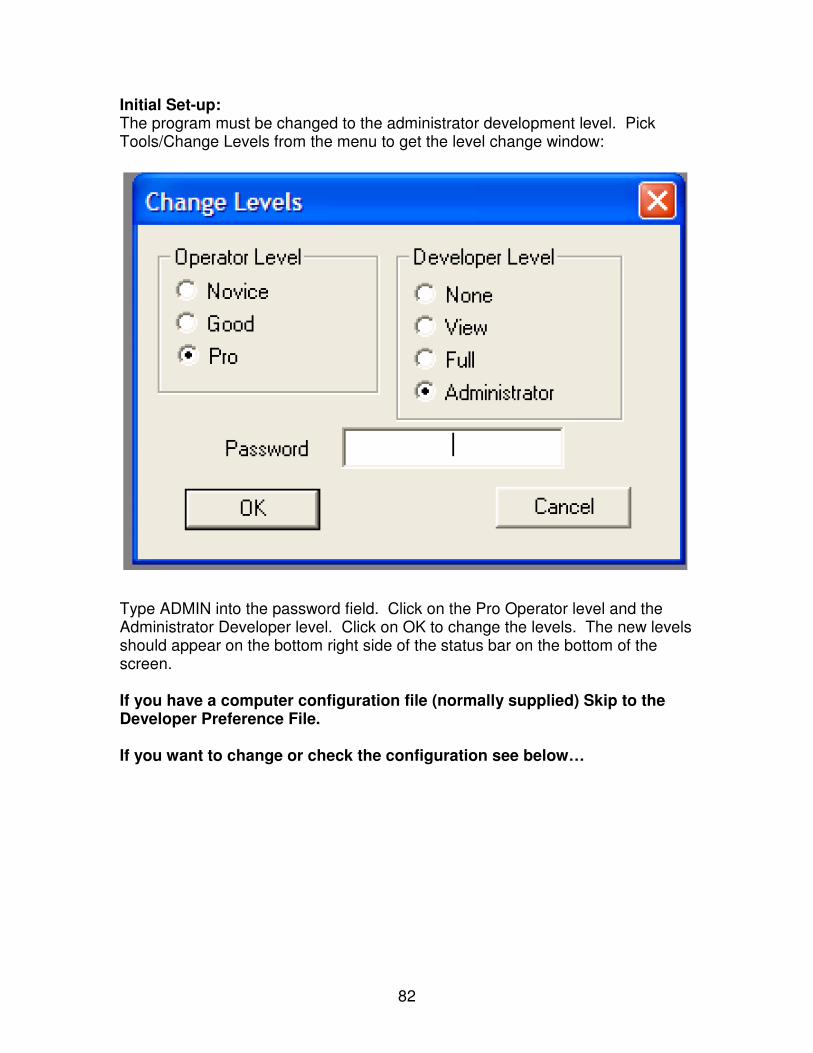
82
Initial Set-up: The program must be changed to the administrator development level. Pick Tools/Change Levels from the menu to get the level change window:
Type ADMIN into the password field. Click on the Pro Operator level and the Administrator Developer level. Click on OK to change the levels. The new levels should appear on the bottom right side of the status bar on the bottom of the screen. If you have a computer configuration file (normally supplied) Skip to the Developer Preference File. If you want to change or check the configuration see below…
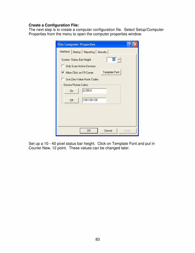
83
Create a Configuration File: The next step is to create a computer configuration file. Select Setup/Computer Properties from the menu to open the computer properties window.
Set up a 10 - 40 pixel status bar height. Click on Template Font and put in Courier New, 12 point. These values can be changed later.

84
Set the Development Level:
Go to the startup tab. Set the starting development level to Administrator and the starting operator level to Pro. Place a check by ‘Skip Interface Start Delay’. Check ‘Demonstration Mode’ if you do not have an actual PLC to communicate with. Go to the reporting tab.
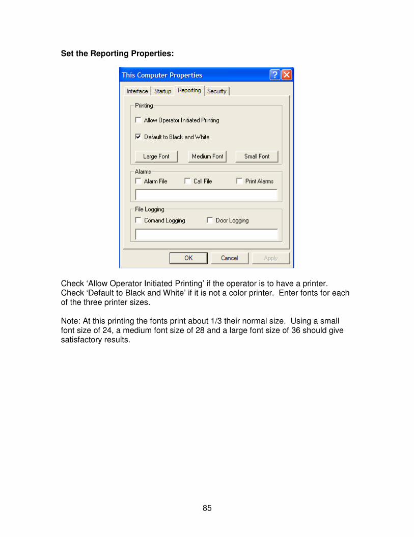
85
Set the Reporting Properties:
Check ‘Allow Operator Initiated Printing’ if the operator is to have a printer. Check ‘Default to Black and White’ if it is not a color printer. Enter fonts for each of the three printer sizes. Note: At this printing the fonts print about 1/3 their normal size. Using a small font size of 24, a medium font size of 28 and a large font size of 36 should give satisfactory results.
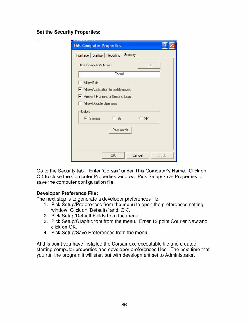
86
Set the Security Properties: .
Go to the Security tab. Enter ‘Corsair’ under This Computer’s Name. Click on OK to close the Computer Properties window. Pick Setup/Save Properties to save the computer configuration file. Developer Preference File: The next step is to generate a developer preferences file.
1. Pick Setup/Preferences from the menu to open the preferences setting window. Click on ‘Defaults’ and ‘OK’.
2. Pick Setup/Default Fields from the menu. 3. Pick Setup/Graphic font from the menu. Enter 12 point Courier New and
click on OK. 4. Pick Setup/Save Preferences from the menu.
At this point you have installed the Corsair.exe executable file and created starting computer properties and developer preferences files. The next time that you run the program it will start out with development set to Administrator.
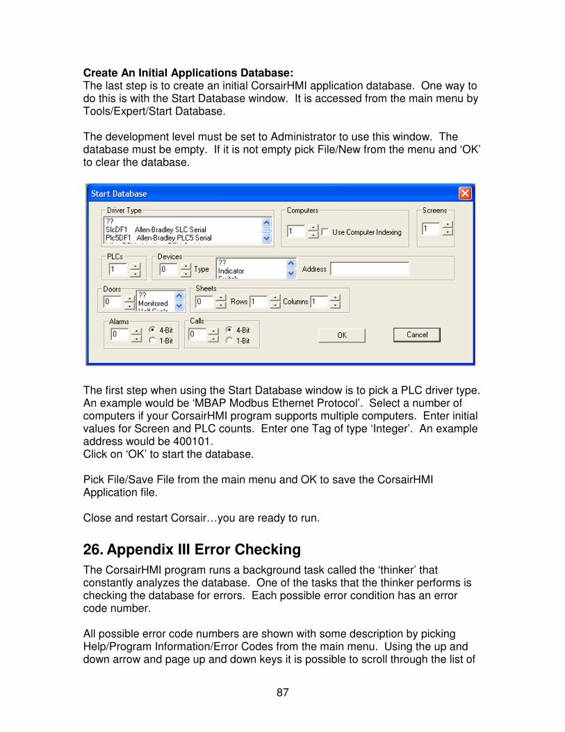
87
Create An Initial Applications Database: The last step is to create an initial CorsairHMI application database. One way to do this is with the Start Database window. It is accessed from the main menu by Tools/Expert/Start Database. The development level must be set to Administrator to use this window. The database must be empty. If it is not empty pick File/New from the menu and ‘OK’ to clear the database.
The first step when using the Start Database window is to pick a PLC driver type. An example would be ‘MBAP Modbus Ethernet Protocol’. Select a number of computers if your CorsairHMI program supports multiple computers. Enter initial values for Screen and PLC counts. Enter one Tag of type ‘Integer’. An example address would be 400101. Click on ‘OK’ to start the database. Pick File/Save File from the main menu and OK to save the CorsairHMI Application file. Close and restart Corsair…you are ready to run.
26. Appendix III Error Checking
The CorsairHMI program runs a background task called the ‘thinker’ that constantly analyzes the database. One of the tasks that the thinker performs is checking the database for errors. Each possible error condition has an error code number. All possible error code numbers are shown with some description by picking Help/Program Information/Error Codes from the main menu. Using the up and down arrow and page up and down keys it is possible to scroll through the list of
88
codes. The list may be printed out when the CorsairHMI program is used to print a manual. Error code numbers are divided into ranges of values. Each range has a name. Each range serves a different purpose. The thinker uses 4 ranges of error codes: 1000-2999 Advice 3000-4999 Alert 5000-6999 Warning 7000-8999 System A summary of the current results from the thinker’s error checking is shown from the main menu with View/Error Summary. System errors are shown on this window. They are errors that apply to the setup of the computer or to deficiencies in the database. Advice, Alert, and Warning errors are applied to individual fields in the development databases. If a field has an error it will be shown in color. The color corresponds to the range of the error. When the developer clicks on the field the description of the error appears in the status bar on the bottom of the window. Clicking on the status bar causes a more complete description of the error to appear. Warning errors are the most severe. Advice errors are the least severe. The recommended CorsairHMI project procedure is to have all warnings fixed before startup. All Alerts should be cleared before leaving the database with a customer. All advice items should be evaluated before the project is closed out. The computer can move through the databases from error to error using Control-N to go to the next error and Control-L to go backwards to the previous error. This error search can be reset to the beginning from the main menu by View/Reset Error Search. There are other ranges of error codes. 9000-9999 Disk 10000-11999 Winsock 12000-12999 Memory 13000-14999 Comms 15000-16999 Notice 59000-60999 Entry 61000-62999 Application 63000-64999 Corrupt Memory
89
Disk errors are concerned with disk file operations. Winsock errors apply to the operation of the computer’s TCP/IP communications software. Memory errors deal with computer memory allocation. Comms errors apply to various problems with communications. Notices are codes to guide the developer in his work. Entry errors spot when data entered into a field is not acceptable. Application errors indicate faults in the CorsairHMI program. Corrupt memory errors indicate problems with the CorsairHMI application database.
27. Appendix IV -PLC Clock Setting
The PLC clock set window is used to monitor and set any PLC time of day clocks that are configured in the application database. The interface must be operating and at least one PLC must be properly configured before the window can be viewed. For a PLC to appear on the screen it must be ‘real’ and the clock field of the PLC database must be set to ‘Yes’ and not have an error. Some drivers will require PLC set up information for clock operations to work. This is entered by zooming on the PLC record. Some PLCs will require special programming with the PLC programming software to interface with the CorsairHMI program. The driver documentation will give details of the requirements. The top line of the window shows the time from the internal clock on the interface computer. This is typically set from the Computer/Control Panel/Date-Time icons in Windows. It cannot be set from within the CorsairHMI program. The Windows operating system will attempt to correct this clock for daylight savings time. The next lines on the window show the name of each real PLC with a properly configured clock followed by the current time of that clock. If the PLCs clock matches the computers clock within three seconds the word ‘Equal!’ will appear after the time. The up and down arrow, page up and down, and home and end keys may be used to scroll through the list of PLCs. If there are multiple PLCs shown the name of one of them will be inversed. The ‘Edit’ menu option will create a window to set the clock on this PLC. That window can change the value of a single clock item or it can download all the values from the computer clock into that PLCs clock. The interface computer checks for proper authority as clock values are changed this way. The PLC clock set window has an option labeled ‘All’. It is used to download the computer clocks values into all of the PLCs that are shown in the window. The development level must be set to ‘Administrator’ for this option to be available. The computer does not check for authority when this option is used.
90
28. Appendix V – Corrections Version Information
Note: This section applies only to the corrections version of CorsairHMI. Operating The Lock Types: The CorsairHMI program may be used to operate different types of doors and locks. The program recognizes how to work a door based upon a door type that has been entered into the computer’s database. Each door type operates in a slightly different fashion. Generally the operator touches the door icon on the screen or moves the mouse cursor next to it and clicks the left mouse button. The screen is now ‘hooked’ to the door. The status bar across the bottom of the screen can be used to verify that the proper door has been hooked. The function keys ‘F1’ through ‘F4’ can be used to operate a door after it has been hooked. Door Type: Monitored: A monitored door cannot be controlled by the computer in any way. The computer only shows its status as ‘secure’ or ‘unsecure’. The switches that are part of the door send this information to the computer. In some cases the door may be closed but still show unsecure if it is not locked. Door Type: Full Cycle: The CorsairHMI program uses the term ‘Full Cycle’ to describe a lock that can be unlocked by the computer. After the computer has unlocked the door, the door may be pulled open and then pushed back closed. The operator does not have to do anything to lock the door. Full cycle locks normally only present an ‘F1-Unlock’ key option to the operator. When the program is operating in a demonstration mode without an actual door, an ‘F2-Close’ key option will be available. Door Type: Half Cycle / Solenoid: The CorsairHMI Program uses the term ‘Half Cycle’ to describe a lock that can be both locked and unlocked by the computer. The operator presses the ‘F1-Unlock’ key to retract the lock bolt on the door. He presses the ‘F2-Lock’ key to allow the door to be secured. The door will show secure on the computer screen only if it has been locked and the door position switch shows that it is in the closed position. Door Type: Sliders and Gates: Sliding doors and gates present three different keys to the operator. They are ‘F1-Open,’ ‘F2-Close,’ and ‘F3-Stop.’ The Stop key may be used to stop the door in mid-travel. It is acceptable to go directly from ‘Open’ to ‘Close’ or from ‘Close’ to ‘Open’ without pressing ‘Stop.’ Timing in the programmable controller will prevent damage from a sudden reversal of the door. Door Type: Dual Cycle: Dual Cycle doors have characteristics of both Full and Half Cycle locks. The interface can present the operator with ‘F1 – Unlock,’ ‘F2-Lock,’ and ‘F4 – Hold’
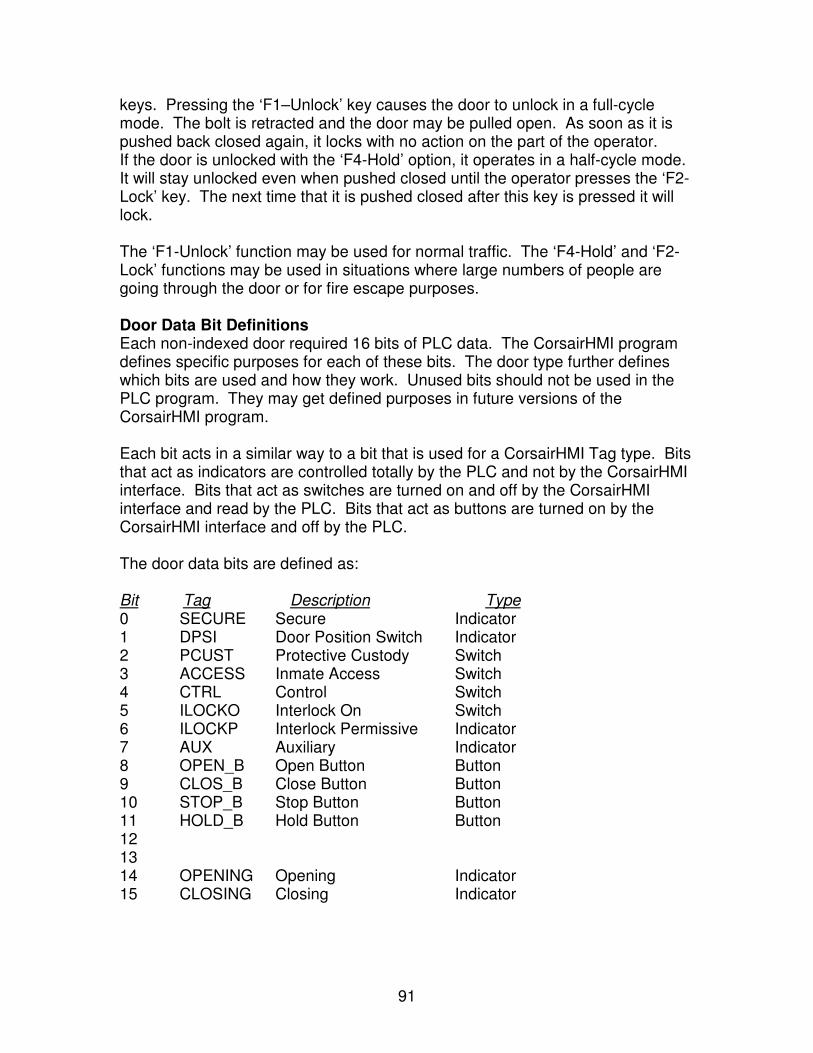
91
keys. Pressing the ‘F1–Unlock’ key causes the door to unlock in a full-cycle mode. The bolt is retracted and the door may be pulled open. As soon as it is pushed back closed again, it locks with no action on the part of the operator. If the door is unlocked with the ‘F4-Hold’ option, it operates in a half-cycle mode. It will stay unlocked even when pushed closed until the operator presses the ‘F2-Lock’ key. The next time that it is pushed closed after this key is pressed it will lock. The ‘F1-Unlock’ function may be used for normal traffic. The ‘F4-Hold’ and ‘F2-Lock’ functions may be used in situations where large numbers of people are going through the door or for fire escape purposes. Door Data Bit Definitions Each non-indexed door required 16 bits of PLC data. The CorsairHMI program defines specific purposes for each of these bits. The door type further defines which bits are used and how they work. Unused bits should not be used in the PLC program. They may get defined purposes in future versions of the CorsairHMI program. Each bit acts in a similar way to a bit that is used for a CorsairHMI Tag type. Bits that act as indicators are controlled totally by the PLC and not by the CorsairHMI interface. Bits that act as switches are turned on and off by the CorsairHMI interface and read by the PLC. Bits that act as buttons are turned on by the CorsairHMI interface and off by the PLC. The door data bits are defined as: Bit Tag Description Type 0 SECURE Secure Indicator 1 DPSI Door Position Switch Indicator 2 PCUST Protective Custody Switch 3 ACCESS Inmate Access Switch 4 CTRL Control Switch 5 ILOCKO Interlock On Switch 6 ILOCKP Interlock Permissive Indicator 7 AUX Auxiliary Indicator 8 OPEN_B Open Button Button 9 CLOS_B Close Button Button 10 STOP_B Stop Button Button 11 HOLD_B Hold Button Button 12 13 14 OPENING Opening Indicator 15 CLOSING Closing Indicator
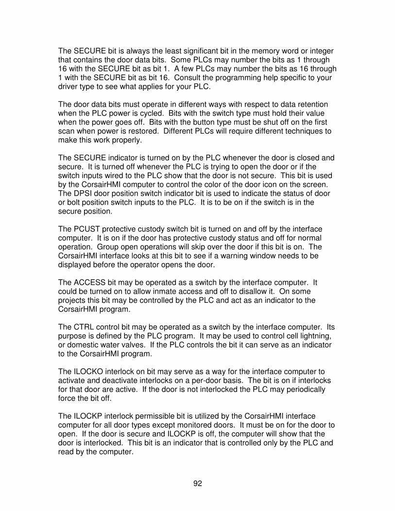
92
The SECURE bit is always the least significant bit in the memory word or integer that contains the door data bits. Some PLCs may number the bits as 1 through 16 with the SECURE bit as bit 1. A few PLCs may number the bits as 16 through 1 with the SECURE bit as bit 16. Consult the programming help specific to your driver type to see what applies for your PLC. The door data bits must operate in different ways with respect to data retention when the PLC power is cycled. Bits with the switch type must hold their value when the power goes off. Bits with the button type must be shut off on the first scan when power is restored. Different PLCs will require different techniques to make this work properly. The SECURE indicator is turned on by the PLC whenever the door is closed and secure. It is turned off whenever the PLC is trying to open the door or if the switch inputs wired to the PLC show that the door is not secure. This bit is used by the CorsairHMI computer to control the color of the door icon on the screen. The DPSI door position switch indicator bit is used to indicate the status of door or bolt position switch inputs to the PLC. It is to be on if the switch is in the secure position. The PCUST protective custody switch bit is turned on and off by the interface computer. It is on if the door has protective custody status and off for normal operation. Group open operations will skip over the door if this bit is on. The CorsairHMI interface looks at this bit to see if a warning window needs to be displayed before the operator opens the door. The ACCESS bit may be operated as a switch by the interface computer. It could be turned on to allow inmate access and off to disallow it. On some projects this bit may be controlled by the PLC and act as an indicator to the CorsairHMI program. The CTRL control bit may be operated as a switch by the interface computer. Its purpose is defined by the PLC program. It may be used to control cell lightning, or domestic water valves. If the PLC controls the bit it can serve as an indicator to the CorsairHMI program. The ILOCKO interlock on bit may serve as a way for the interface computer to activate and deactivate interlocks on a per-door basis. The bit is on if interlocks for that door are active. If the door is not interlocked the PLC may periodically force the bit off. The ILOCKP interlock permissible bit is utilized by the CorsairHMI interface computer for all door types except monitored doors. It must be on for the door to open. If the door is secure and ILOCKP is off, the computer will show that the door is interlocked. This bit is an indicator that is controlled only by the PLC and read by the computer.
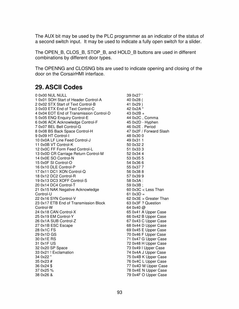
93
The AUX bit may be used by the PLC programmer as an indicator of the status of a second switch input. It may be used to indicate a fully open switch for a slider. The OPEN_B, CLOS_B, STOP_B, and HOLD_B buttons are used in different combinations by different door types. The OPENNG and CLOSNG bits are used to indicate opening and closing of the door on the CorsairHMI interface.
29. ASCII Codes 0 0x00 NUL NULL 1 0x01 SOH Start of Header Control-A 2 0x02 STX Start of Text Control-B 3 0x03 ETX End of Text Control-C 4 0x04 EOT End of Transmission Control-D 5 0x05 ENQ Enquiry Control-E 6 0x06 ACK Acknowledge Control-F 7 0x07 BEL Bell Control-G 8 0x08 BS Back Space Control-H 9 0x09 HT Control-I 10 0x0A LF Line Feed Control-J 11 0x0B VT Control-K 12 0x0C FF Form Feed Control-L 13 0x0D CR Carriage Return Control-M 14 0x0E SO Control-N 15 0x0F SI Control-O 16 0x10 DLE Control-P 17 0x11 DC1 XON Control-Q 18 0x12 DC2 Control-R 19 0x13 DC3 XOFF Control-S 20 0x14 DC4 Control-T 21 0x15 NAK Negative Acknowledge Control-U 22 0x16 SYN Control-V 23 0x17 ETB End of Transmission Block Control-W 24 0x18 CAN Control-X 25 0x19 EM Control-Y 26 0x1A SUB Control-Z 27 0x1B ESC Escape 28 0x1C FS 29 0x1D GS 30 0x1E RS 31 0x1F US 32 0x20 SP Space 33 0x21 ! Exclamation 34 0x22 " 35 0x23 # 36 0x24 $ 37 0x25 % 38 0x26 &
39 0x27 ' 40 0x28 ( 41 0x29 ) 42 0x2A * 43 0x2B + 44 0x2C , Comma 45 0x2D - Hyphen 46 0x2E . Period 47 0x2F / Forward Slash 48 0x30 0 49 0x31 1 50 0x32 2 51 0x33 3 52 0x34 4 53 0x35 5 54 0x36 6 55 0x37 7 56 0x38 8 57 0x39 9 58 0x3A : 59 0x3B ; 60 0x3C < Less Than 61 0x3D = 62 0x3E > Greater Than 63 0x3F ? Question 64 0x40 @ 65 0x41 A Upper Case 66 0x42 B Upper Case 67 0x43 C Upper Case 68 0x44 D Upper Case 69 0x45 E Upper Case 70 0x46 F Upper Case 71 0x47 G Upper Case 72 0x48 H Upper Case 73 0x49 I Upper Case 74 0x4A J Upper Case 75 0x4B K Upper Case 76 0x4C L Upper Case 77 0x4D M Upper Case 78 0x4E N Upper Case 79 0x4F O Upper Case
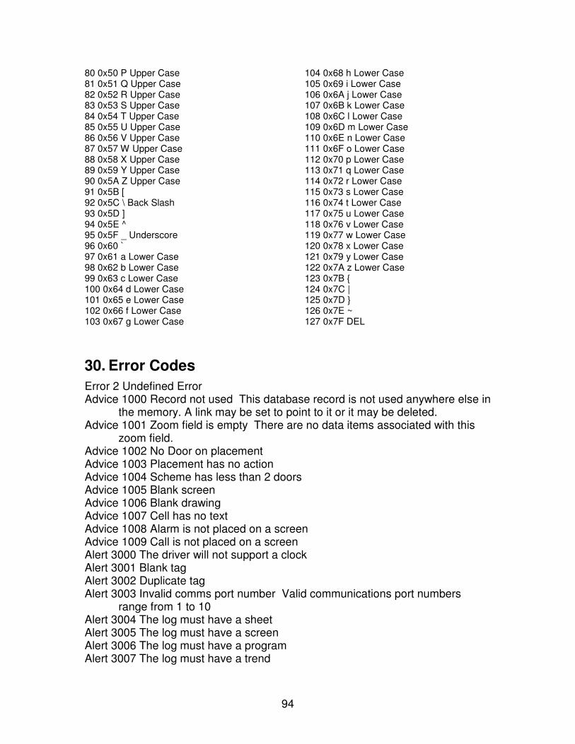
94
80 0x50 P Upper Case 81 0x51 Q Upper Case 82 0x52 R Upper Case 83 0x53 S Upper Case 84 0x54 T Upper Case 85 0x55 U Upper Case 86 0x56 V Upper Case 87 0x57 W Upper Case 88 0x58 X Upper Case 89 0x59 Y Upper Case 90 0x5A Z Upper Case 91 0x5B [ 92 0x5C \ Back Slash 93 0x5D ] 94 0x5E ^ 95 0x5F _ Underscore 96 0x60 ` 97 0x61 a Lower Case 98 0x62 b Lower Case 99 0x63 c Lower Case 100 0x64 d Lower Case 101 0x65 e Lower Case 102 0x66 f Lower Case 103 0x67 g Lower Case
104 0x68 h Lower Case 105 0x69 i Lower Case 106 0x6A j Lower Case 107 0x6B k Lower Case 108 0x6C l Lower Case 109 0x6D m Lower Case 110 0x6E n Lower Case 111 0x6F o Lower Case 112 0x70 p Lower Case 113 0x71 q Lower Case 114 0x72 r Lower Case 115 0x73 s Lower Case 116 0x74 t Lower Case 117 0x75 u Lower Case 118 0x76 v Lower Case 119 0x77 w Lower Case 120 0x78 x Lower Case 121 0x79 y Lower Case 122 0x7A z Lower Case 123 0x7B { 124 0x7C | 125 0x7D } 126 0x7E ~ 127 0x7F DEL
30. Error Codes
Error 2 Undefined Error Advice 1000 Record not used This database record is not used anywhere else in
the memory. A link may be set to point to it or it may be deleted. Advice 1001 Zoom field is empty There are no data items associated with this
zoom field. Advice 1002 No Door on placement Advice 1003 Placement has no action Advice 1004 Scheme has less than 2 doors Advice 1005 Blank screen Advice 1006 Blank drawing Advice 1007 Cell has no text Advice 1008 Alarm is not placed on a screen Advice 1009 Call is not placed on a screen Alert 3000 The driver will not support a clock Alert 3001 Blank tag Alert 3002 Duplicate tag Alert 3003 Invalid comms port number Valid communications port numbers
range from 1 to 10 Alert 3004 The log must have a sheet Alert 3005 The log must have a screen Alert 3006 The log must have a program Alert 3007 The log must have a trend
95
Alert 3008 The log must have a plc Alert 3009 The log must have some tags Warning 5000 IP Address Zero Four zeros is not a valid IP address. Warning 5001 IP Address all 255 Four values of 255 is not a valid IP address. Warning 5002 IP Address matches this computer The specified IP address
matches this computer. There appears to be an address conflict. Warning 5003 Blank Address Warning 5004 Invalid Data Type Warning 5005 Zero Element Warning 5006 Element Number too High Warning 5007 Can't find this computer There must be a record in the computer
database that has a name that matches the name in the Computer Properties
Warning 5008 XXXXXXXX This computer name matches more than one record Warning 5009 Invalid driver type Warning 5010 Address cannot be changeable Warning 5011 Invalid data file number Warning 5012 No Element Number Warning 5013 Different File Types on Same File Number Warning 5014 Address cannot have bit Warning 5015 Invalid bit number Warning 5016 Address must be numeric Warning 5017 Address alignment error Warning 5018 Address Index out of range Warning 5019 Door needs a type Warning 5020 Tag needs a type Warning 5021 Driver needs a type Warning 5022 Address cannot be indexed Warning 5023 This driver only supports 0X coils and 4X registers Warning 5024 The address is not a valid address for this driver type. The driver
only supports a specific list of addresses. Print About the driver for a list of these addresses.
Warning 5025 GPS tag data is never changeable from Corsair System 7000 No data in application Database development work must be
started or an application file must be loaded from the disk drive. System 7001 No computer records System 7002 Can't find a printer System 7003 No splash icon The program has been configured to show a
splash icon. This is a bitmap that is loaded from a Corsair.bmp bitmap file when the program first runs. The bitmap did not load.
System 7004 Program is already running System 7005 Standard blocks in the database do not match the program. Clear
and re-load the standard blocks. System 7006 Too many screens for this Version The database contains too
many screens for this version of the program. You need to reduce the
96
database or buy a different version. You will not be able to view all of your screens.
System 7007 Must be only 1 computer record This version of the Corsair program only allows one record in the computer database.
System 7008 No MB Host computer for this remote System 7009 Invalid MB Primary Host computer for this remote System 7010 MB Primary Host computer needs MIS IP Address System 7011 The MB Primary Host computer has not been set up for Host
operation System 7012 Invalid MB Secondary Host computer for this remote System 7013 MB Secondary Host computer needs MIS IP Address System 7014 The MB Secondary Host computer has not been set up for Host
operation System 7015 This software will only run when configured as an MB Remote. System 7016 Demonstration Version Time-Out This version of the Corsair
program can only run the interface for a limited period of time. That time has expired. You must turn the interface on again.
System 7017 Application File Name is empty System 7018 Application Nickname is empty System 7019 Errors exist in the Application File List System 7020 Duplicate nicknames exist among enabled Application files System 7021 License file error An error occurred while trying to load the license
file. See Setup/See License Error for more information. Disk 9000 Can't open disk file The file may not exist. The name and path
specification may be invalid. The logged-in user may not have the correct rights to read or write the path or drive.
Disk 9001 Disk write error Disk 9002 Disk read error Disk 9003 Bad disk data Disk 9004 File Close Error Disk 9005 No File Name A valid file name needs to be specified, Disk 9006 The specified name is a directory, not a file. Disk 9007 File or path not found Disk 9008 Invalid value in disk file Disk 9009 The specified name is a directory, not a file, or else the file is read-
only. Disk 9010 Can't find license file Disk 9011 License file date has expired The license file is not a permanent one.
It is past the expiration date. Once a license file has expired it cannot work again even if the clock on the computer is turned back. A new license file is needed.
Disk 9012 License file checksum error The data in the license file is corrupt. A new license file is needed.
Disk 9013 A license must cover at least one computer Disk 9014 MBHR requires at least 2 database computers
97
Winsock 10013 Winsock Access Error Winsock 10014 Winsock Fault Winsock 10024 Too Many Open Files Winsock 10036 WINSOCK.DLL in progress Winsock 10040 Message Too Long Winsock 10041 Protocol wrong type for socket Winsock 10042 Bad Protocol Option Winsock 10043 Protocol not Supported Winsock 10049 Address not available Winsock 10050 Network Down Winsock 10051 Network Unreachable Winsock 10054 Connection Reset Winsock 10055 No Buffer Space Available Winsock 10057 Socket not connected Winsock 10060 Connection timed out Winsock 10061 Connection refused Winsock 10065 Host not reachable Winsock 10067 WINSOCK.DLL at user limit - too many processes Winsock 10091 WINSOCK.DLL not found or not functioning The program cannot
find the TCP/IP stack dynamic link library file. Another possibility is that the DLL is not functioning correctly. It may not be properly installed or configured.
Winsock 10092 WINSOCK.DLL wrong version Memory 12000 Can't increase record memory Memory 12001 Failure to create data Memory 12002 Can't increase bulk memory Memory 12003 Can't get enough memory Memory 12004 Can't get record memory from the OS Memory 12005 Can't get bulk data memory from the OS Memory 12006 Disabled application has some memory Memory 12007 Application has no allocated memory Comms 13000 No-reply time-out The Corsair program sent a message to the
PLC but did not get a reply within the allowed time. Comms 13001 MB 1 Illegal Function Comms 13002 MB 2 Illegal Data Address The address may not be implemented
in the PLC Comms 13003 MB 3 Illegal data value Comms 13004 MB 4 Slave Device Failure or Illegal Response Length Comms 13008 MB 8 Memory Parity Error Comms 13050 Wrong Reply Function Code Comms 13051 Reply packet is short Comms 13052 Data type can't be read from PLC Comms 13053 STS Error Comms 13054 Misc TCP/IP Error Comms 13055 Can't get Socket
98
Comms 13056 Will not Connect to PLC The computer cannot establish a connection to the PLC. Check the PLC IP address in the PLC database. Check to make sure that the PLC is powered up and connected to the network. Make sure that the sub-net numbers of the computer and PLC match.
Comms 13057 No Reply to Hook-up Comms 13058 Can't set socket to not block Comms 13059 TCP Failure on Connect Request Comms 13060 PLC CPU Busy Error Comms 13061 Address data type cannot be written Comms 13062 Port is not available Comms 13063 Port is not open Comms 13064 Port must have 8 data bits Comms 13065 Checksum Error on Reply Comms 13066 Port transmit time-out Comms 13067 PLC is not real Comms 13068 Interface was shut off Comms 13069 Comms Read requested length is too long Comms 13070 Comms Write requested length is too long Comms 13071 TCP/IP would not transmit Comms 13072 Connection Reset Comms 13073 Address cannot do a mask write Comms 13074 Invalid address type Comms 13075 Error fetching the IP address for a name Comms 13076 Error fetching the Name for an IP address Comms 13077 Connection Closed Comms 13078 Ping destination is unreachable Comms 13079 Ping timeout Comms 13080 MAPI32.dll did not load Comms 13081 Could not get pointer to a MAPI function Comms 13082 Failure to log into to MAPI for email Comms 13083 Insufficient memory for email Comms 13084 Too many email sessions already open Comms 13085 Unspecified MAPI logon error Comms 13086 Ambiguous Recipient on email message Comms 13087 Email Attachment not Found Comms 13088 Email Attachment could not be opened Comms 13089 Email bad recipient type Comms 13090 Unspecified email send error Comms 13091 Insufficient memory to send email Comms 13092 Email recipients invalid or did not resolve to address Comms 13093 Email login failure Comms 13094 Email message text too large Comms 13095 Email too many file attachments Comms 13096 Email too many recipients Comms 13097 Email unknown recipient
99
Comms 13098 Computer Properties not set to email Comms 13099 Email no recipients Comms 13100 Email blank address Comms 13101 Email Group is not on this computer Comms 13102 Invalid Email Group Comms 13103 Port is in use by another task Comms 13104 TCP Port Number is Zero Comms 14999 Bad Function Code or Data Length Notice 15000 Good File Save Notice 15001 Good File Load Notice 15002 Interface must be on Notice 15003 No real PLCs with clocks Notice 15004 No data to export Notice 15005 Export is not turned on Notice 15006 Good File Export Notice 15007 Interface must be off Notice 15008 No data to zoom into Notice 15009 Password does not match The password that you typed in does
not match any of the acceptable passwords in the list. Notice 15010 The driver that you selected does not support an architecture
window. Notice 15011 Enter a valid address Notice 15012 Enter a valid non-zero length Notice 15013 Can't find a placement with that hook code Notice 15014 Address not supported by this function Notice 15015 The data log is not set up to be viewed by an operator. Notice 15016 Not viewable on this computer Notice 15017 Not runnable on this computer Notice 15018 Can't execute the data log Notice 15019 No viewer available for the data log Notice 15020 Can't open default printer Notice 15021 PLC has no I/O modules Notice 15022 Data log needs a name for the default file name Notice 15023 A file name must be specified Notice 15024 No file name tag data Notice 15025 File name needs a tag Notice 15026 A standard block has not been selected Notice 15027 Date field must be switched on Notice 15028 Time field must be switched on Notice 15029 From Time Equals To Time Notice 15030 From Time After To Time Notice 15031 No Tags on Graph Notice 15032 Set time is after the time right now Notice 15033 The computer can try to get the information that it needs to update
this placement on a turned-back screen. A log that includes the tag exists. Data for the desired time must be in the log's file.
100
Notice 15034 The computer does not need to consider any tags to update this placement on a turned-back screen. It will always be shown. Notice 15035 This type of placement cannot be updated on a turned-back
screen. Corsair Codes Printed by Lab 2-1 on Thu Dec 04 13:37:05 2008 Page 24 of 28 Notice 15036 The action that has been assigned to this placement means that it cannot be updated on a turned-back screen. Notice 15037 This placement is skipped on this computer. Notice 15038 This placement cannot be displayed on a turned-back screen because at least one of the indexes is not zero. Notice 15039 Value placements that use selector tags cannot be updated on turned-back screens. Notice 15040 The computer cannot update this placement on a turned-back screen because of problems with the configuration of one or more tags. Notice 15041 This tag is not on a log that can provide valid history information or the log is not running on this computer. Notice 15042 The tag must have a non-zero blanking interval entered on the log. Notice 15043 This option is not available on a MB Remote computer Notice 15044 The database does not contain a PLC that uses Modbus style
addresses Notice 15045 There were no MBHR addresses to clear Notice 15046 Tank diameter is zero or negative Notice 15047 Tank length is zero or negative Notice 15048 The database must have a non-Modbus PLC Notice 15049 The block is not enabled Notice 15050 Needs a name Notice 15051 Needs a tag prefix Notice 15052 Invalid Modbus ID Notice 15053 Modbus ID is already in use on this port Notice 15054 Modbus ID is already in use on this IP address Notice 15055 Application database must be empty Notice 15056 Source application is not enabled Notice 15057 Destination application is not enabled Notice 15058 Copy destination is not empty Notice 15059 Source and destination are the same Notice 15060 Source is not a valid application Notice 15061 Source must be 1-100 Notice 15062 Destination must be 1-100 Notice 15063 Merge Destination is Empty - Use Copy instead Notice 15064 Merge Destination is not a valid application Notice 15065 Processor does not support CPU ID Notice 15066 PLC does not use the CIP protocol Runtime 17000 This block only works when assigned to a tag
101
Runtime 17001 The authority level setting will not allow the block to execute Runtime 17002 Invalid comms port number on the block Runtime 17003 The block is not being solved because the interface is off Runtime 17004 The block will not run because the port must be set for 7 data bits
(not 8) Runtime 17005 The first parameter must be an array of integers for row position Runtime 17006 The second parameter must be an array of integers for column
position Runtime 17007 The block is in the start-up delay time period Runtime 17008 The time period must not be zero Runtime 17009 The block cannot work with the data type or data format Runtime 17010 The block result tag type is invalid Runtime 17011 Parameter A is invalid Runtime 17012 Parameter B is invalid Runtime 17013 Parameter C is invalid Runtime 17014 Parameter D is invalid Runtime 17015 Parameter E is invalid Runtime 17016 Parameter F is invalid Runtime 17017 Parameter G is invalid Runtime 17018 Parameter H is invalid Runtime 17019 Parameter I is invalid Runtime 17020 Parameter J is invalid Runtime 17021 The Result Parameter is invalid Runtime 17022 Cannot do the tag type conversion The combination of tag types
and/or formats makes it impossible to convert from one to the other. The data is incompatible.
Runtime 17023 Divide by Zero Error Runtime 17024 Invalid tag type Runtime 17025 Array size is zero Runtime 17026 Index over array size Runtime 17027 Memory buffer size is zero Runtime 17028 Invalid string length Runtime 17029 Operation would go past the end of the buffer Runtime 17030 Cannot write that much data to the PLC at one time Runtime 17031 PF cannot be zero Database Change 57000 A color was changed on a trend Database Change 57001 At least one graphic placement was moved Database Change 57002 Setup data was changed on a PLC Database Change 57003 Setup data was changed on a driver Database Change 57004 A link connecting one record to another was changed Database Change 57005 Width or height was changed on a placement Database Change 57006 A point on a placement was moved Database Change 57007 A character string was changed Database Change 57008 The data format of a tag was changed Database Change 57009 A color was changed Database Change 57010 The type subcode of a record was changed
102
Database Change 57011 The IP address on a record was changed Database Change 57012 A time interval in seconds was changed Database Change 57013 A time interval in milliseconds was changed Database Change 57014 A time-out value was changed Database Change 57015 A Yes/No field on a record was changed Database Change 57016 A link between two records was changed (sheet style
database editing) Database Change 57017 A record was moved to a different parent Database Change 57018 Database records were sorted Database Change 57019 A memory unit was deleted Database Change 57020 A memory unit was inserted Database Change 57021 An enumeration of a tag was changed Database Change 57022 Text justification was changed Database Change 57023 The action of a placement was changed Database Change 57024 A Yes/No field on a placement was changed Database Change 57025 A floating-point value on a placement was changed Database Change 57026 A color on a placement was changed Database Change 57027 A tag index on a placement was changed Database Change 57028 A value on a placement was changed Database Change 57029 A template tag number was changed Database Change 57030 A template tag bit number was changed Database Change 57031 A template tag index number was changed Database Change 57032 An I/O point label was changed Database Change 57033 A line style on a placement was changed Database Change 57034 Arc fill on a placement was changed Database Change 57035 The font was changed on a placement Database Change 57036 The value of a number field was changed Database Change 57037 The value of a floating-point field was changed Database Change 57038 The type of a sheet cell was changed Database Change 57039 A Yes/No parameter on a sheet cell was changed Database Change 57040 A tag index value on a sheet cell was changed Database Change 57041 A tag index shift on a sheet cell was changed Database Change 57042 The repeat count on a sheet cell was changed Database Change 57043 A constant value on a sheet cell was changed Database Change 57044 A link to a tag on a sheet cell was changed Database Change 57045 A Yes/No field on a log was changed Database Change 57046 A link connecting a record to a log was changed Database Change 57047 A tag index on a log was changed Database Change 57048 A time interval on a log was changed Database Change 57049 A time of day on a log was changed Database Change 57050 The action of a log was changed Database Change 57051 The object of a log action was changed Database Change 57052 The file naming mode for a log was changed Database Change 57053 The file format for a log was changed Database Change 57054 The file purge days on a log were changed Database Change 57055 The operator viewability of a log was changed
103
Database Change 57056 The on-change status of a tag on a log was changed Database Change 57057 The on-change logging differential on a logged tag was
changed Database Change 57058 The plot trace color of a logged tag was changed Database Change 57059 The blanking interval of a logged tag was changed Database Change 57060 A tag was assigned to a log Database Change 57061 Standard blocks were installed Database Change 57062 Standard blocks were cleared Database Change 57063 Size was changed on a block variable Database Change 57064 Type was changed on a block variable Database Change 57065 Format was changed on a block variable Database Change 57066 Length was changed on a block variable Database Change 57067 Block parameter tag Yes/No field was changed Database Change 57068 A block parameter constant was changed Database Change 57069 Address index on a computer was changed Database Change 57070 IP Address on a computer was changed Database Change 57071 Logging minimum on a tag was changed Database Change 57072 Logging maximum on a tag was changed Database Change 57073 The type of a driver was changed Database Change 57074 The port number on a driver was changed Database Change 57075 The IP Address on a PLC was changed Database Change 57076 A value on a trend was changed Database Change 57077 Grids on a trend were changed Database Change 57078 A Yes/No field on a trend was changed Database Change 57079 Plot sample count on a trend was changed Database Change 57080 The width time of a trend was changed Database Change 57081 Digit count on a trend was changed Database Change 57082 Overlap flag on a tag was changed Database Change 57083 Changeable flag on a tag was changed Database Change 57084 Indexing type of a tag was changed Database Change 57085 Array size of a tag was changed Database Change 57086 The type of a tag was changed Database Change 57087 The length of a string tag was changed Database Change 57088 The Private status of a register block was changed Database Change 57089 The OIT Changeable status of a register block was
changed Database Change 57090 The All status of a register block was changed Database Change 57091 The type of the standard template on an I/O module
was changed Database Change 57092 The background color on an i/o module was changed Database Change 57093 A rack, slot, or position value on a module was
changed Database Change 57094 MIS IP Address on a computer was changed Database Change 57095 MBHR Host status of a computer was changed Database Change 57096 MBHR Remote status of a computer was changed
104
Database Change 57097 MBHR Remote Write status of a computer was changed
Database Change 57098 The Real flag on a PLC was changed Database Change 57099 The Clock flag on a PLC was changed Database Change 57100 The MBHR ID of a PLC was changed Database Change 57101 The sample time of a tag was changed Database Change 57102 The sample period of a tag was changed Database Change 57103 The extended protocol status of an MB Remote was
changed Database Change 57104 A parameter on a block was changed Database Change 57105 Size was changed on a program variable Database Change 57106 Type was changed on a program variable Database Change 57107 Format was changed on a program variable Database Change 57108 Length was changed on a program variable Database Change 57109 A program variable was assigned as a block result Database Change 57110 A program variable was assigned to a block parameter Database Change 57111 Color on a trend tag was changed Database Change 57112 Width of a sheet cell was changed Database Change 57113 A block variable was changed Database Change 57114 A time of day was changed Database Change 57115 A MBHR host port number was changed Thinker Result 58000 Thinker did sortation of Address Tree Thinker Result 58001 Thinker cleared out unused memory units Thinker Result 58002 Thinker resized memory for a tag Thinker Result 58003 Thinker compiled data for viewing history Thinker Result 58004 Thinker marked whether or not a record is on this
computer Thinker Result 58005 Thinker corrected an error code number Thinker Result 58006 Thinker corrected links to block records Thinker Result 58007 Thinker calculated if a log is used on this computer Thinker Result 58008 Thinker corrected the uses count on a record Thinker Result 58009 Thinker corrected if a door is interlocked Thinker Result 58010 Thinker noted a driver type Thinker Result 58011 Thinker sorted records Thinker Result 58012 Thinker calculated if a plc is real Thinker Result 58013 Thinker calculated if a plc has a clock Thinker Result 58014 Thinker calculated if a plc battery can be monitored Thinker Result 58015 Thinker adjusted the minimum connect times on a driver Thinker Result 58016 Thinker corrected out-of-range intervals on a log Thinker Result 58017 Thinker checked if a log is triggered on value changes Thinker Result 58018 Thinker corrected an invalid value in memory Thinker Result 58019 Thinker corrected a string length Thinker Result 58020 Thinker adjusted a tag format Thinker Result 58021 Thinker adjusted PLC parameters based upon the driver
type
105
Thinker Result 58022 Thinker calculated if a tag is on a PLC or is only in Corsair memory
Thinker Result 58023 Thinker adjusted the trend sampling parameters on a tag record
Thinker Result 58024 Thinker calculated if a tag is being used as a password Thinker Result 58025 Thinker calculated if a tag is being used for an authority
level Thinker Result 58026 Thinker calculated if a tag is being used for door name text Thinker Result 58027 Thinker adjusted parameters on a trend Thinker Result 58028 Thinker calculated the nesting level of a tree item Thinker Result 58029 Thinker calculated if a log triggers on this computer Thinker Result 58030 Thinker corrected a link from a program instruction to a
block Entry 59000 All values must be <= 255 Entry 59001 Needs a numeric value Entry 59002 Too many digits Entry 59003 Value too big for field Entry 59004 Value below the minimum Entry 59005 Value above the maximum Entry 59006 Left digits 1-31, Right digits 0-7 Entry 59007 Value can't be negative Entry 59008 No matching records Entry 59009 Development is not turned on Entry 59010 Administration is not turned on Entry 59011 Nothing to delete Entry 59012 Viewing Development Not Allowed Entry 59013 Operator Level is not high enough Entry 59014 Must be Y or N for Yes or No Entry 59015 No matching letters Entry 59016 No more values allowed Entry 59017 Invalid value Entry 59018 No History Tags Available Entry 59019 There are no standard blocks in the database Entry 59020 Blank Entry Entry 59021 File viewing is not enabled Entry 59022 History viewing is not enabled Entry 59023 MAC addresses need 6 parts Entry 59024 MAC address cannot be zero Entry 59025 License file name is too short Entry 59026 License file name must start with CHMI Entry 59027 License file name must end in .CKY Entry 59028 Time-Out must be at least one minute Application 61000 Corsair Program Fault Application 61001 Illegal PLC comms state Application 61002 Invalid Comms Request Code Application 61003 Illegal Driver comms state

106
Application 61004 Zero length on plc comms Application 61005 Illegal comms task request Application 61006 Illegal block solve type Corrupt Memory 64991 Bulk data not large enough for type Corrupt Memory 64992 Zero Parent Link Corrupt Memory 64993 Bad Record Memory Pointer Corrupt Memory 64994 Can't lock memory Corrupt Memory 64995 Illegal memory unit type code Corrupt Memory 64996 Bad bulk data pointer Corrupt Memory 64997 Missing parent link Corrupt Memory 64998 Bad link values Corrupt Memory 64999 Bad memory pointers
31. Drivers - ASCII Polling Driver
The ASCII polling driver is used by the CorsairHMI program to exchange data with several types of Tags over a serial communications link. The CorsairHMI program initiates data read and write commands to a slave Tag. The slave Tag remains silent until it receives a request from the computer. Tag on PLCs that use the ASCII polling driver cannot be indexed. The size of the Tag cannot be greater than one. It cannot be computer indexed. . The general format for data packets that are used by the driver is:
Leading Characters, Prefix, Data, Suffix, Trailing Characters The driver can use from 0 to 3 lead characters and from 0 to 3 trailing characters. All packets sent and received by the computer must use the same lead and trailing characters. A typical system would use no lead and two trailing characters. They would frequently be an ASCII carriage return followed by a line feed. ASCII Expert Windows The CorsairHMI ASCII expert menu options access two windows that are a help when setting up the polling driver. The first window is an ASCII character table. It shows the characters as 7-bit decimal numbers from 0 to 127, hex numbers from 0x00 to 0x7F, the corresponding character, and other information. The table may be viewed as a window on the CorsairHMI computer screen and it may be printed as a part of the project manual. The next window is the communications trace window. It is used to monitor the characters that the CorsairHMI program transmits out of and receives into its serial ports.
107
Driver Setup The first step in configuring the ASCII polling driver is to set up the computer serial port properties. CorsairHMI supports up to 10 ports that are numbered 1 through 10. The first four use standardized port names. Ports 5 through 10 may have other names. The baud rate, parity selection, and number of data and stop bits need to be set up on the desired ports. The ASCII polling driver is not designed to use the most significant bit of an 8-bit character. If 8 data bits are used the most significant bit will be masked off on both transmit and receive. The next step is to create a driver record with the ASCII polling driver type. The serial port number must be assigned to the driver. Zooming on the driver PLC field enables creating PLC records. Each PLC record corresponds to a piece of equipment that is hooked to the serial communications link. Several pieces of slave equipment can be hooked to the same serial line in a multi-drop system. This would require a single driver and several PLC records. If each piece of equipment is hooked to a separate serial port on the CorsairHMI computer (up to 10) a separate driver and PLC record must be created for each one. PLC Setup The time-out field on the PLC record is used to set the time that the CorsairHMI computer allows for the remote equipment to respond to a read request. Zooming on a PLC record opens the PLC’s driver-related setup window. For the ASCII polling driver it contains the following items: Number of leading characters, 0-3 First leading ASCII character, decimal Second leading ASCII character, decimal Third leading ASCII character, decimal Number of trailing characters, 0-3 First trailing ASCII character, decimal Second trailing ASCII character, decimal Third trailing ASCII character, decimal Capitalize on Write Data Transmit, Y/N Capitalize on Read Data Receive, Y/N Space Crunch on Write Data Transmit, Y/N Space Crunch on Read Data Receive, Y/N End of Successful Read delay, mSec End of Write delay, mSec If leading or trailing characters are used they are put on all data packets that the CorsairHMI program transmits to the equipment. They are expected to be on all data packets that the CorsairHMI program receives from the equipment. The characters are entered here as decimal values. 10 would be used for a line feed and 13 for a carriage return. All possible values are listed on the CorsairHMI ASCII table window. Values above 127 are not allowed.
108
CorsairHMI can automatically force all lower-case characters in the data portion of packets to upper-case capitals if desired on receive or on transmit. Space Crunching is removal of ‘white-space’ characters like spaces and tabs. It also only applies to the data portion of packets. The CorsairHMI program can insert a time delay after completion of a successful read or write operation. Delays after reads can be used to reduce communications traffic on slave equipment that has a slow processor. Delays after writes can be used to wait through write reply packets that are not recognized by the ASCII polling driver. Tag Addressing The CorsairHMI computer gets the characters that it needs to transmit and receive for a Tag from the address of the Tag. The address is a single string with up to 5 parts. Each part is surrounded by double quotes and separated by commas.
“Part 1”,”Part 2”,”Part 3”,”Part 4”,”Part 5”, The address string can be a maximum of 64 characters long. Quotes and commas are counted into this 64 character total. The functions of the parts are:
Part 1: Read Data Request Part 2: Read Data Reply Prefix Part 3: Read Data Reply Suffix Part 4: Write Data Request Prefix Part 5: Write Data Request Suffix
Parts 1 through 3 are required for all Tag tags that are to use the driver for communication. Parts 4 and 5 are used on computer-changeable tags where the CorsairHMI computer needs to write data into the equipment. When CorsairHMI wants to read data from a piece of equipment the ASCII polling driver sends this data packet:
Leading Characters, Read Data Request, Trailing Characters The equipment that the data is read from replies with:
Leading Characters, Read Data Reply Prefix, Read Data, Read Data Reply Suffix, Trailing Characters
109
The Read Data section of the packet is where the characters are that are used to set data into the Tag tag. The capitalization and space-crunch setup options only apply to this part of the packet. When CorsairHMI wants to write data into a piece of equipment the ASCII polling driver sends this data packet:
Leading Characters, Write Data Request Prefix, Write Data, Write Data Request Suffix, Trailing Characters
The Write Data section of the packet is where the characters are that are used by the equipment to determine what value is being written. These characters are the text representation of the current value of the Tag. The capitalization and space-crunch setup options only apply to this part of the packet. The CorsairHMI ASCII polling driver is not set up to look for and accept any sort of reply after a data write. It is recommended that the PLC be setup with an end-of-write delay to get through any write reply characters that are returned by the slave equipment. Address Part Syntax In the simplest case an address part is text inside quotes followed by a comma.
“ABCD”, This part specifies 4 characters. They are the ASCII for the letter A followed by the ASCII for B, C, and D. Sometimes an address part is not used. These ‘empty’ parts are shown by two sets of quotes with nothing between followed by a comma:
“”, It is possible to embed a quote character inside an address part by putting two quotes in a row:
“AB””CD”, This part specifies 5 characters – first A, then B, then one double quote, then C, then D. Additional flexibility with address parts is possible with backslash codes. The first use of backslash codes is to embed ASCII characters from 0 to 31 and 127 into an address part. The syntax is a backslash followed by the ASCII name of the character followed by another backslash. For example:
110
“A\CR\\LF\”, This specifies three characters – the letter ‘A’ followed by a carriage return (decimal 13) followed by a line feed (decimal 10). The ASCII names must match exactly the format (including case) that is shown in the CorsairHMI ASCII table window. A literal backslash is specified by two backslashes in a row:
“AB\\CD”, This part specifies 5 characters – first A, then B, then one backslash, then C, then D. A special slash code is TD for ‘time delay’ in milliseconds:
“AB\TD500\CD”, Time delay slash codes are only used in Read or Write Request address parts. They are never used in Reply address parts.
32. Drivers – Maple Silver Series
Maple Terminal Driver Maple 520 HMI terminals can be set up to operate in a master-slave fashion over Ethernet. One terminal acts as a Master. The master may talk to a PLC over a serial port. Other Slave terminals read and write data to the master. The CorsairHMI program contains a driver that can communicate over Ethernet to a Maple terminal. CorsairHMI emulates a Maple acting as a slave. The Maple must have its Multiple HMI parameter set to ‘Master’. Its Connect I/F parameter must be set to ‘Ethernet’. It needs to be assigned an IP address with an appropriate subnet mask. A typical subnet mask value would be 255.255.255.0. The default Route IP address on the Maple would usually be 0.0.0.0. The CorsairHMI database needs to have a driver configured to talk to a Maple terminal. Each PLC that is zoomed under the driver corresponds to a terminal. Each Maple is set up for a protocol that it uses to talk to PLC equipment. There is a unique code number for each protocol. This number needs to be entered into each PLC record on the CorsairHMI database. Driver-specific information like this is set with a special zoom field on the PLC record. The developer can

111
click on the tag name of the plc and then hit ‘Z’ or F7 to zoom. Pressing F2 will enable entry of the protocol code number. CorsairHMI addresses for the Maple driver make it possible to read data from the memory of the Maple or to read ‘through’ the Maple and read the PLC directly. The read-through method is not recommended unless it is absolutely necessary. Data that is read from the PLC should be transferred to Maple memory periodically using a data transfer inside the Maple. Multiple CorsairHMI computers can then read the Maple data without causing traffic problem on the PLC communications link. CorsairHMI Maple addresses are formatted as in these examples: W0:180:100 B0:161:5 The first character is always a B for Bit memory or a W for Word memory. This is followed by a decimal number. This number should be zero when reading from memory in the Maple. It is used as a PLC slave identifier when reading through the Maple. As an example, there may be a string of three RS-485 serial Modbus Tags hooked to the Maple. The Modbus protocol supports a slave address. In this case they may be 1, 2, and 3. The first number of the CorsairHMI address corresponds to this slave address. Entering a 1, 2, or a 3 would tell the Maple which slave to use for the Tag tag. This number is followed by a colon. The second number is a memory type number. These numbers are assigned by Maple as a part of the protocol. Maple provides a text file that lists these values. Examples include: Terminal RB Recipe Bits – 160 Terminal LB Local Bits – 161 Terminal RW Recipe Words – 180 Terminal LW Local Words – 181 All other values of these codes are dependent on the choice of protocol that the Maple uses. This code number is followed by a colon. The third number is the offset within the memory type. As an example: W0:180:2 Terminal Recipe Word RW2 B0:161:1 Terminal Local Bit LB1 Values may be set in the PLC by using a ‘Set’ button for the value on the CorsairHMI interface. The operator could enter a value and then turn on the button to trigger a Maple macro that sets the value into the PLC. The PLC may also read the value from the Maple and reset the ‘Set’ bit when successful. Maple supports ‘read through’ of the master and to access PLC registers directly,
112
however this function is not currently supported in Corsair. Not all Tags can be accessed in ‘read through” mode. Some values may be written from the CorsairHMI interface to the PLCs supporting this function. Maple memory data needs to be assigned with a view toward data retention. RB and RW recipe data is retained upon power cycling of the terminal. LB and LW data must be forced to zero in the Maple start-up screen if it is required to be in a known state. Maple does not force variables to zero at start-up unless the Set command is used. RB and RW data share memory space in the Maple. See Maple TN1096 for details of the shared memory space. Strings are limited to 32 characters by the Maple. The following recommendations should be considered: Data that is logged in CorsairHMI data logs – RB and RW Switch Tags – RB Button Tags – LB Indicators that must retain – RB Indicators that trigger CorsairHMI actions like logging – LB
33. Additional Driver Information
************************** ABCLX - Allen-Bradley Logix Uses a serial port Uses TCP/IP Needs a PLC node address Needs a PLC IP address Uses Modbus Addresses Can read a PLC clock Selectable read combination Cannot combine reads Can read battery status Can use Register Monitor Show Driver Error Show Driver Status Only Reads One PLC at a time Can do Computer Indexing Separate Read and Write status Calc Register Block Lengths Uses PLC Time-Out CIP Protocol Driver is finished and ready for unrestricted use - - - - - - - - - - - - - - - - Timeout: 0.5s minimum, 1m maximum, 3s default - - - - - - - - - - - - - - - - This driver is to be used with the AB family of Logix processors. It is not complete. ************************** ASCII Poll - Simple ASCII Polling Uses a serial port Uses TCP/IP
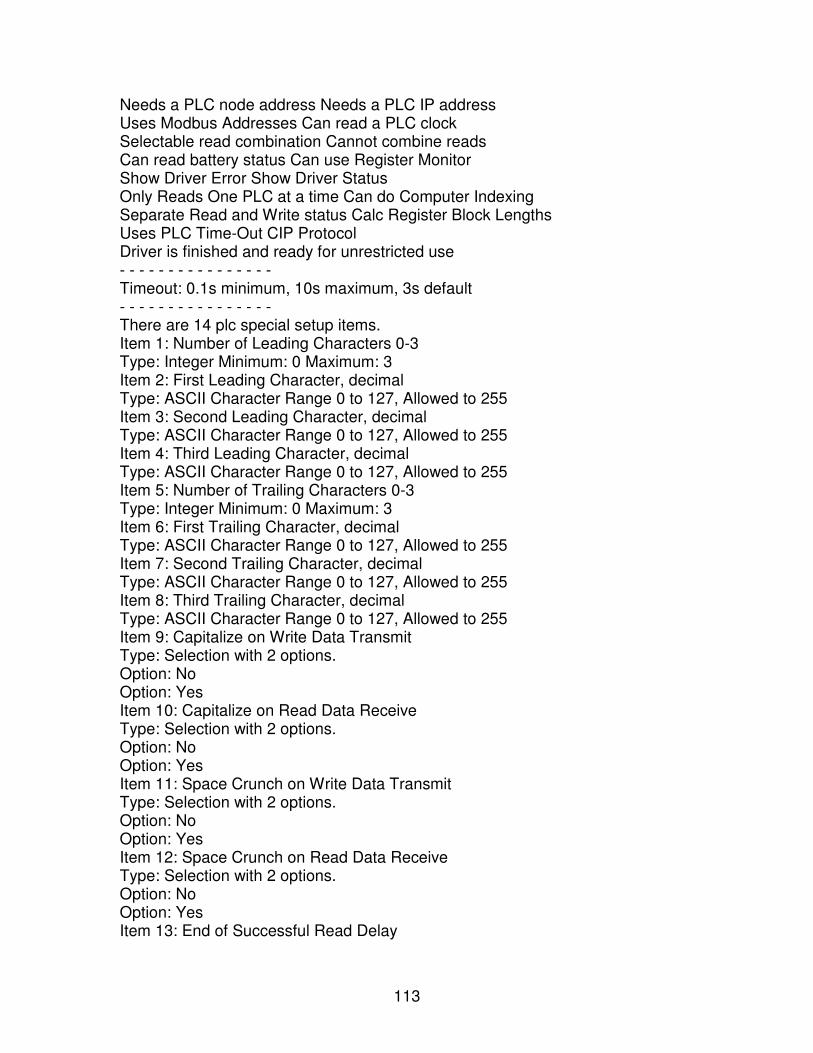
113
Needs a PLC node address Needs a PLC IP address Uses Modbus Addresses Can read a PLC clock Selectable read combination Cannot combine reads Can read battery status Can use Register Monitor Show Driver Error Show Driver Status Only Reads One PLC at a time Can do Computer Indexing Separate Read and Write status Calc Register Block Lengths Uses PLC Time-Out CIP Protocol Driver is finished and ready for unrestricted use - - - - - - - - - - - - - - - - Timeout: 0.1s minimum, 10s maximum, 3s default - - - - - - - - - - - - - - - - There are 14 plc special setup items. Item 1: Number of Leading Characters 0-3 Type: Integer Minimum: 0 Maximum: 3 Item 2: First Leading Character, decimal Type: ASCII Character Range 0 to 127, Allowed to 255 Item 3: Second Leading Character, decimal Type: ASCII Character Range 0 to 127, Allowed to 255 Item 4: Third Leading Character, decimal Type: ASCII Character Range 0 to 127, Allowed to 255 Item 5: Number of Trailing Characters 0-3 Type: Integer Minimum: 0 Maximum: 3 Item 6: First Trailing Character, decimal Type: ASCII Character Range 0 to 127, Allowed to 255 Item 7: Second Trailing Character, decimal Type: ASCII Character Range 0 to 127, Allowed to 255 Item 8: Third Trailing Character, decimal Type: ASCII Character Range 0 to 127, Allowed to 255 Item 9: Capitalize on Write Data Transmit Type: Selection with 2 options. Option: No Option: Yes Item 10: Capitalize on Read Data Receive Type: Selection with 2 options. Option: No Option: Yes Item 11: Space Crunch on Write Data Transmit Type: Selection with 2 options. Option: No Option: Yes Item 12: Space Crunch on Read Data Receive Type: Selection with 2 options. Option: No Option: Yes Item 13: End of Successful Read Delay
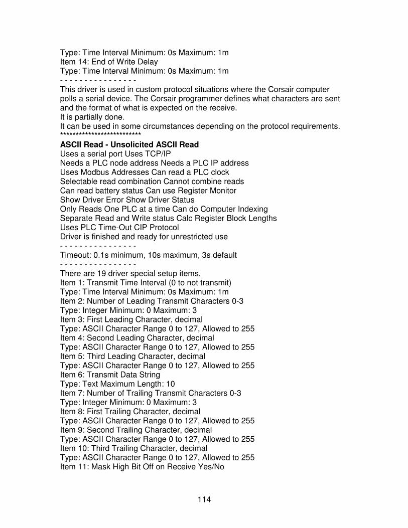
114
Type: Time Interval Minimum: 0s Maximum: 1m Item 14: End of Write Delay Type: Time Interval Minimum: 0s Maximum: 1m - - - - - - - - - - - - - - - - This driver is used in custom protocol situations where the Corsair computer polls a serial device. The Corsair programmer defines what characters are sent and the format of what is expected on the receive. It is partially done. It can be used in some circumstances depending on the protocol requirements. ************************** ASCII Read - Unsolicited ASCII Read Uses a serial port Uses TCP/IP Needs a PLC node address Needs a PLC IP address Uses Modbus Addresses Can read a PLC clock Selectable read combination Cannot combine reads Can read battery status Can use Register Monitor Show Driver Error Show Driver Status Only Reads One PLC at a time Can do Computer Indexing Separate Read and Write status Calc Register Block Lengths Uses PLC Time-Out CIP Protocol Driver is finished and ready for unrestricted use - - - - - - - - - - - - - - - - Timeout: 0.1s minimum, 10s maximum, 3s default - - - - - - - - - - - - - - - - There are 19 driver special setup items. Item 1: Transmit Time Interval (0 to not transmit) Type: Time Interval Minimum: 0s Maximum: 1m Item 2: Number of Leading Transmit Characters 0-3 Type: Integer Minimum: 0 Maximum: 3 Item 3: First Leading Character, decimal Type: ASCII Character Range 0 to 127, Allowed to 255 Item 4: Second Leading Character, decimal Type: ASCII Character Range 0 to 127, Allowed to 255 Item 5: Third Leading Character, decimal Type: ASCII Character Range 0 to 127, Allowed to 255 Item 6: Transmit Data String Type: Text Maximum Length: 10 Item 7: Number of Trailing Transmit Characters 0-3 Type: Integer Minimum: 0 Maximum: 3 Item 8: First Trailing Character, decimal Type: ASCII Character Range 0 to 127, Allowed to 255 Item 9: Second Trailing Character, decimal Type: ASCII Character Range 0 to 127, Allowed to 255 Item 10: Third Trailing Character, decimal Type: ASCII Character Range 0 to 127, Allowed to 255 Item 11: Mask High Bit Off on Receive Yes/No
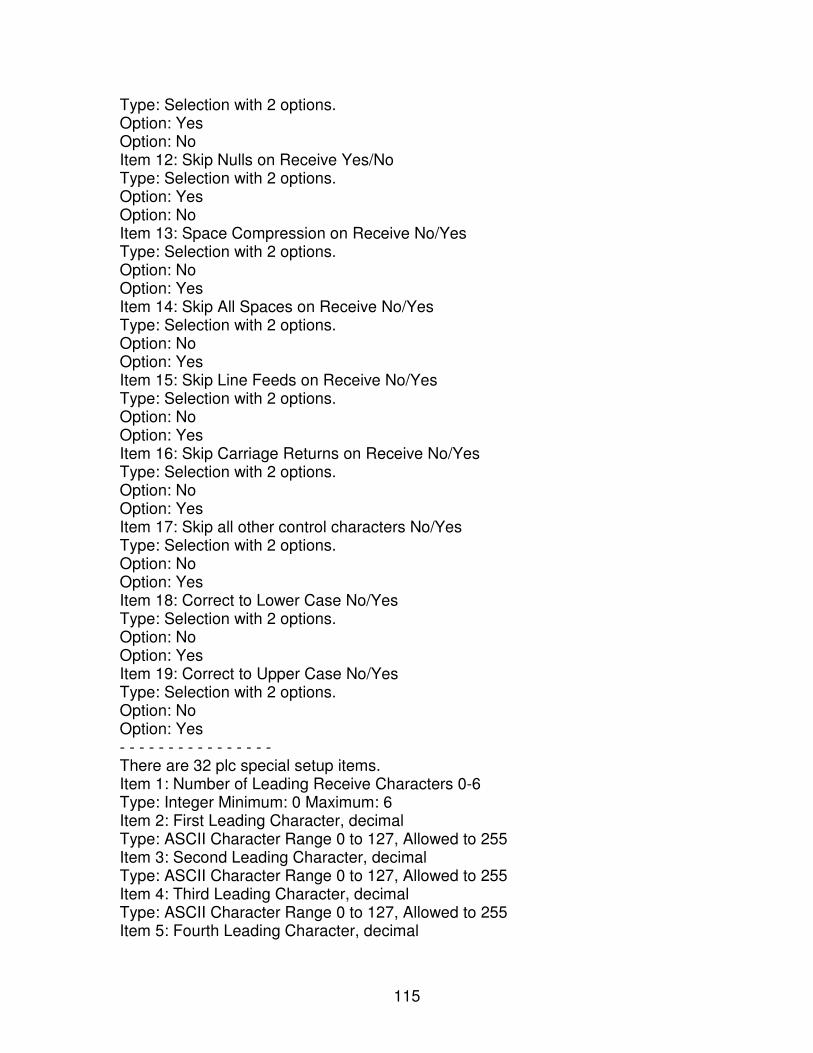
115
Type: Selection with 2 options. Option: Yes Option: No Item 12: Skip Nulls on Receive Yes/No Type: Selection with 2 options. Option: Yes Option: No Item 13: Space Compression on Receive No/Yes Type: Selection with 2 options. Option: No Option: Yes Item 14: Skip All Spaces on Receive No/Yes Type: Selection with 2 options. Option: No Option: Yes Item 15: Skip Line Feeds on Receive No/Yes Type: Selection with 2 options. Option: No Option: Yes Item 16: Skip Carriage Returns on Receive No/Yes Type: Selection with 2 options. Option: No Option: Yes Item 17: Skip all other control characters No/Yes Type: Selection with 2 options. Option: No Option: Yes Item 18: Correct to Lower Case No/Yes Type: Selection with 2 options. Option: No Option: Yes Item 19: Correct to Upper Case No/Yes Type: Selection with 2 options. Option: No Option: Yes - - - - - - - - - - - - - - - - There are 32 plc special setup items. Item 1: Number of Leading Receive Characters 0-6 Type: Integer Minimum: 0 Maximum: 6 Item 2: First Leading Character, decimal Type: ASCII Character Range 0 to 127, Allowed to 255 Item 3: Second Leading Character, decimal Type: ASCII Character Range 0 to 127, Allowed to 255 Item 4: Third Leading Character, decimal Type: ASCII Character Range 0 to 127, Allowed to 255 Item 5: Fourth Leading Character, decimal
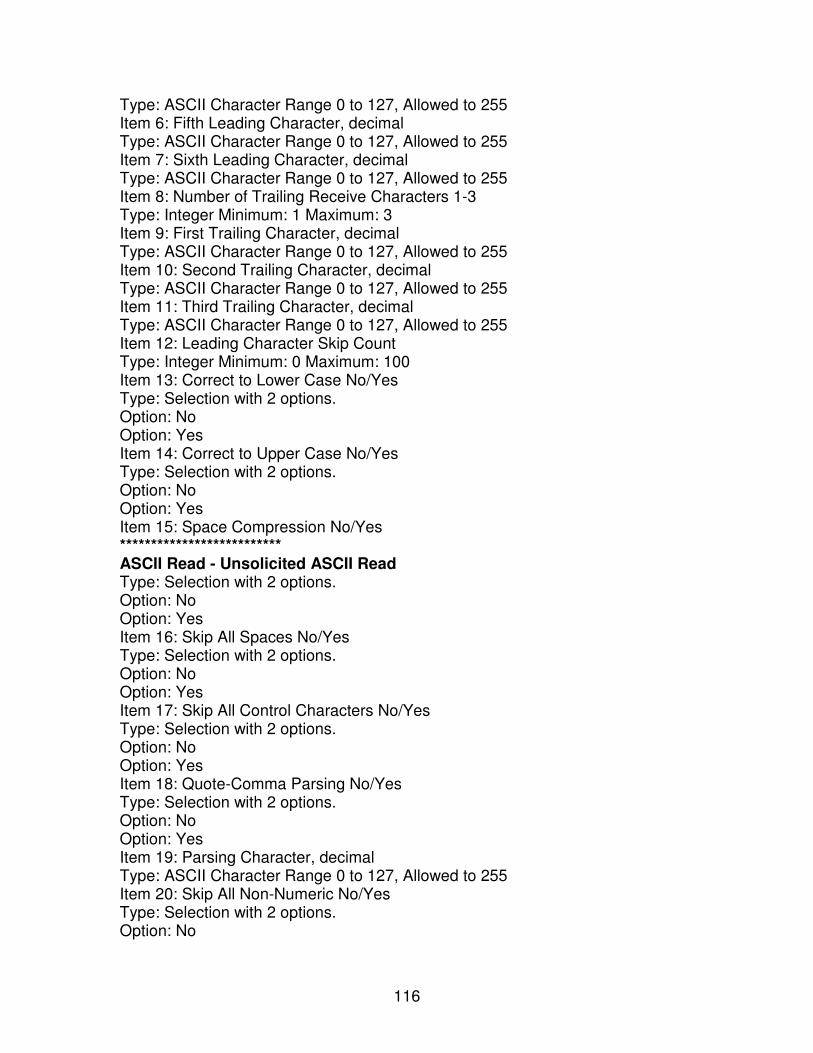
116
Type: ASCII Character Range 0 to 127, Allowed to 255 Item 6: Fifth Leading Character, decimal Type: ASCII Character Range 0 to 127, Allowed to 255 Item 7: Sixth Leading Character, decimal Type: ASCII Character Range 0 to 127, Allowed to 255 Item 8: Number of Trailing Receive Characters 1-3 Type: Integer Minimum: 1 Maximum: 3 Item 9: First Trailing Character, decimal Type: ASCII Character Range 0 to 127, Allowed to 255 Item 10: Second Trailing Character, decimal Type: ASCII Character Range 0 to 127, Allowed to 255 Item 11: Third Trailing Character, decimal Type: ASCII Character Range 0 to 127, Allowed to 255 Item 12: Leading Character Skip Count Type: Integer Minimum: 0 Maximum: 100 Item 13: Correct to Lower Case No/Yes Type: Selection with 2 options. Option: No Option: Yes Item 14: Correct to Upper Case No/Yes Type: Selection with 2 options. Option: No Option: Yes Item 15: Space Compression No/Yes ************************** ASCII Read - Unsolicited ASCII Read Type: Selection with 2 options. Option: No Option: Yes Item 16: Skip All Spaces No/Yes Type: Selection with 2 options. Option: No Option: Yes Item 17: Skip All Control Characters No/Yes Type: Selection with 2 options. Option: No Option: Yes Item 18: Quote-Comma Parsing No/Yes Type: Selection with 2 options. Option: No Option: Yes Item 19: Parsing Character, decimal Type: ASCII Character Range 0 to 127, Allowed to 255 Item 20: Skip All Non-Numeric No/Yes Type: Selection with 2 options. Option: No
117
Option: Yes Item 21: Match Character 1 Position 0,1- Type: Integer Minimum: 0 Maximum: 300 Item 22: Match Character 1, decimal Type: ASCII Character Range 0 to 127, Allowed to 255 Item 23: Match Character 2 Position 0,1- Type: Integer Minimum: 0 Maximum: 300 Item 24: Match Character 2, decimal Type: ASCII Character Range 0 to 127, Allowed to 255 Item 25: Match Character 3 Position 0,1- Type: Integer Minimum: 0 Maximum: 300 Item 26: Match Character 3, decimal Type: ASCII Character Range 0 to 127, Allowed to 255 Item 27: Match Field 1 Position 0,1- Type: Integer Minimum: 0 Maximum: 300 Item 28: Match Field 1 Text Type: Text Maximum Length: 10 Item 29: Match Field 2 Position 0,1- Type: Integer Minimum: 0 Maximum: 300 Item 30: Match Field 2 Text Type: Text Maximum Length: 10 Item 31: Match Field 3 Position 0,1- Type: Integer Minimum: 0 Maximum: 300 Item 32: Match Field 3 Text Type: Text Maximum Length: 10 - - - - - - - - - - - - - - - - There are 3 reserved device addresses. Address: Field Purpose: Indicates which data field - format is Field## Tag Type: String Address: Timed Out Purpose: Signal a read time-out condition Tag Type: Indicator Address: Complete Purpose: Signal completion of reading a packet Tag Type: Indicator - - - - - - - - - - - - - - - - This driver is used in custom protocol situations where the Corsair computer reads data from a serial communication line. Corsair can periodically transmit fixed data but this driver does not do true polling. True polling involves sending and then waiting for a reply. Most instruments used with this driver send data without being solicited. The driver is not complete. **************************
118
CALEnet - CAL Controller over Ethernet Uses a serial port Uses TCP/IP Needs a PLC node address Needs a PLC IP address Uses Modbus Addresses Can read a PLC clock Selectable read combination Cannot combine reads Can read battery status Can use Register Monitor Show Driver Error Show Driver Status Only Reads One PLC at a time Can do Computer Indexing Separate Read and Write status Calc Register Block Lengths Uses PLC Time-Out CIP Protocol Driver is finished and ready for unrestricted use - - - - - - - - - - - - - - - - Timeout: 0.1s minimum, 10s maximum, 3s default Node Number: 0 minimum, 255 maximum - - - - - - - - - - - - - - - - There are 2 plc special setup items. Item 1: Is it a 9500? Type: Selection with 2 options. Option: No Option: Yes Item 2: Process Variable Units Type: Selection with 2 options. Option: Temperature Option: Special - - - - - - - - - - - - - - - - This driver is used to communicate with one or more CAL controllers through Ethernet. The controllers are hooked to an Ethernet to Serial converter. The driver uses a single IP address and a single TCP connection. All PLCs on it should have the same IP address. Corsair differentiates between the controllers by using the 1-byte node address. The driver is not complete. ************************** CALSer - CAL Controller Serial Uses a serial port Uses TCP/IP Needs a PLC node address Needs a PLC IP address Uses Modbus Addresses Can read a PLC clock Selectable read combination Cannot combine reads Can read battery status Can use Register Monitor Show Driver Error Show Driver Status Only Reads One PLC at a time Can do Computer Indexing Separate Read and Write status Calc Register Block Lengths Uses PLC Time-Out CIP Protocol Driver is finished and ready for unrestricted use - - - - - - - - - - - - - - - -
119
Timeout: 0.1s minimum, 10s maximum, 3s default Node Number: 0 minimum, 255 maximum - - - - - - - - - - - - - - - - There are 2 plc special setup items. Item 1: Is it a 9500? Type: Selection with 2 options. Option: No Option: Yes Item 2: Process Variable Units Type: Selection with 2 options. Option: Temperature Option: Special - - - - - - - - - - - - - - - - This driver is used to communicate with one or more CAL controllers through a serial port. It differentiates between controllers by using the 1-byte node address. ************************** GPS - NMEA Compatible GPS Serial Uses a serial port Uses TCP/IP Needs a PLC node address Needs a PLC IP address Uses Modbus Addresses Can read a PLC clock Selectable read combination Cannot combine reads Can read battery status Can use Register Monitor Show Driver Error Show Driver Status Only Reads One PLC at a time Can do Computer Indexing Separate Read and Write status Calc Register Block Lengths Uses PLC Time-Out CIP Protocol Driver is finished and ready for unrestricted use - - - - - - - - - - - - - - - - Timeout: 1s minimum, 1m maximum, 5s default - - - - - - - - - - - - - - - - There are 5 reserved device addresses. Address: Latitude Purpose: Latitude (North-South) Position Tag Type: Double Int Format: Latitude Address: Longitude Purpose: Longitude (East-West) Position Tag Type: Double Int Format: Longitude Address: Speed Knots Purpose: Speed in Knots Tag Type: Double Float Format: -3.2 Address: Speed MPH Purpose: Speed in Miles Per Hour Tag Type: Double Float Format: -3.2 Address: Timed Out Purpose: Signal a read time-out condition

120
Tag Type: Indicator - - - - - - - - - - - - - - - - This driver is used to communicate with a GPS receiver over a serial port. It is not complete. ************************** GeSrtp - General Electric Series 90 TCP/IP Uses a serial port Uses TCP/IP Needs a PLC node address Needs a PLC IP address Uses Modbus Addresses Can read a PLC clock Selectable read combination Cannot combine reads Can read battery status Can use Register Monitor Show Driver Error Show Driver Status Only Reads One PLC at a time Can do Computer Indexing Separate Read and Write status Calc Register Block Lengths Uses PLC Time-Out CIP Protocol Driver is finished and ready for unrestricted use - - - - - - - - - - - - - - - - Timeout: 0.5s minimum, 1m maximum, 3s default - - - - - - - - - - - - - - - - This driver is used with GE Series 90 PLCs over Ethernet ************************** InterApp - Corsair Inter-Application Data Exchange Uses a serial port Uses TCP/IP Needs a PLC node address Needs a PLC IP address Uses Modbus Addresses Can read a PLC clock Selectable read combination Cannot combine reads Can read battery status Can use Register Monitor Show Driver Error Show Driver Status Only Reads One PLC at a time Can do Computer Indexing Separate Read and Write status Calc Register Block Lengths Uses PLC Time-Out CIP Protocol Driver is finished and ready for unrestricted use - - - - - - - - - - - - - - - - This driver is used to send data from one application to another when both are loaded by the same Corsair program. It cannot be used to communicate between Corsair programs. The driver is not complete. ************************** MBAP - Modbus Ethernet Application Protocol Uses a serial port Uses TCP/IP Needs a PLC node address Needs a PLC IP address Uses Modbus Addresses Can read a PLC clock Selectable read combination Cannot combine reads Can read battery status Can use Register Monitor Show Driver Error Show Driver Status Only Reads One PLC at a time Can do Computer Indexing
121
Separate Read and Write status Calc Register Block Lengths Uses PLC Time-Out CIP Protocol Driver is finished and ready for unrestricted use - - - - - - - - - - - - - - - - Timeout: 0.5s minimum, 1m maximum, 3s default Node Number: 0 minimum, 255 maximum - - - - - - - - - - - - - - - - There are 7 plc special setup items. Item 1: Clock Register Block 4X##### (8 registers) Type: Integer Minimum: 0 Maximum: 65528 Item 2: Disable Mask Write Function 22 Type: Selection with 2 options. Option: No Option: Yes Item 3: Battery Low Coil 0X##### Type: Integer Minimum: 0 Maximum: 65528 Item 4: Combine Reads if Possible Type: Selection with 2 options. Option: Yes Option: No Item 5: Use IEC Style Addresses Type: Selection with 2 options. Option: No Option: Yes Item 6: Allow Indexing Type: Selection with 2 options. Option: Yes Option: No Item 7: TCP Port Number (0 defaults to 502) Type: Integer Minimum: 0 Maximum: 65535 - - - - - - - - - - - - - - - - This is the most commonly used Modbus Ethernet driver. It acts as a Client (master) only, not as a Server (slave). It can communicate with many PLCs simultaneously on separate TCP sockets. It transmits the 1-byte node address that the developer has entered but most servers will not use it. ************************** MBEMD - Modbus Ethernet Multi-Drop Uses a serial port Uses TCP/IP Needs a PLC node address Needs a PLC IP address Uses Modbus Addresses Can read a PLC clock Selectable read combination Cannot combine reads Can read battery status Can use Register Monitor Show Driver Error Show Driver Status Only Reads One PLC at a time Can do Computer Indexing
122
Separate Read and Write status Calc Register Block Lengths Uses PLC Time-Out CIP Protocol Driver is finished and ready for unrestricted use - - - - - - - - - - - - - - - - Timeout: 0.5s minimum, 1m maximum, 3s default Node Number: 0 minimum, 255 maximum - - - - - - - - - - - - - - - - There are 7 plc special setup items. Item 1: Clock Register Block 4X##### (8 registers) Type: Integer Minimum: 0 Maximum: 65528 Item 2: Disable Mask Write Function 22 Type: Selection with 2 options. Option: No Option: Yes Item 3: Battery Low Coil 0X##### Type: Integer Minimum: 0 Maximum: 65528 Item 4: Combine Reads if Possible Type: Selection with 2 options. Option: Yes Option: No Item 5: Use IEC Style Addresses Type: Selection with 2 options. Option: No Option: Yes Item 6: Allow Indexing Type: Selection with 2 options. Option: Yes Option: No Item 7: TCP Port Number (0 defaults to 502) Type: Integer Minimum: 0 Maximum: 65535 - - - - - - - - - - - - - - - - This driver is very similar to the MBAP Modbus Ethernet driver except that it has been modified to use only a single TCP/IP socket connection. It uses only 1 IP address for multiple PLCs. It differentiates between PLCs by using the 1-byte node address. It is designed especially for use with Modbus Ethernet to serial converters. ************************** MBEMDE - Modbus Ethernet Multi-Drop Extended Uses a serial port Uses TCP/IP Needs a PLC node address Needs a PLC IP address Uses Modbus Addresses Can read a PLC clock Selectable read combination Cannot combine reads Can read battery status Can use Register Monitor Show Driver Error Show Driver Status Only Reads One PLC at a time Can do Computer Indexing
123
Separate Read and Write status Calc Register Block Lengths Uses PLC Time-Out CIP Protocol Driver is finished and ready for unrestricted use - - - - - - - - - - - - - - - - Timeout: 0.5s minimum, 1m maximum, 3s default Node Number: 0 minimum, 255 maximum - - - - - - - - - - - - - - - - There is 1 plc special setup item. Item 1: TCP Port Number (0 defaults to 502) Type: Integer Minimum: 0 Maximum: 65535 - - - - - - - - - - - - - - - - This driver is identical to the MBEMD driver except that it uses special extensions to the Modbus Ethernet Protocol to allow for larger packet sizes. It may be only be used in special circumstances to read data from another Corsair computer that is acting as an MBHR host. ************************** MBMM - Modbus Memory Map Uses a serial port Uses TCP/IP Needs a PLC node address Needs a PLC IP address Uses Modbus Addresses Can read a PLC clock Selectable read combination Cannot combine reads Can read battery status Can use Register Monitor Show Driver Error Show Driver Status Only Reads One PLC at a time Can do Computer Indexing Separate Read and Write status Calc Register Block Lengths Uses PLC Time-Out CIP Protocol Driver is finished and ready for unrestricted use - - - - - - - - - - - - - - - - There are 4 plc special setup items. Item 1: File Name Type: Text Maximum Length: 128 Item 2: 4X Register Count Type: Other Item 3: File is Volatile No/Yes Type: Selection with 2 options. Option: No Option: Yes Item 4: Periodic Refresh Time (0 to disable) Type: Time Interval Minimum: 0s Maximum: 10m - - - - - - - - - - - - - - - - This driver is designed to read and write data to a binary-format disk file that is organized as a Modbus register map. It can handle volatile file data that is read and
124
written from several different Corsair computers. The term 'volatile' means that the file can be written from any computer at any time. If a computer needs to change data in a volatile file it will always read the file in, change the data, and write it back in a single action. Work on this driver has not been started. ************************** MBRTU - Modbus RTU Serial Uses a serial port Uses TCP/IP Needs a PLC node address Needs a PLC IP address Uses Modbus Addresses Can read a PLC clock Selectable read combination Cannot combine reads Can read battery status Can use Register Monitor Show Driver Error Show Driver Status Only Reads One PLC at a time Can do Computer Indexing Separate Read and Write status Calc Register Block Lengths Uses PLC Time-Out CIP Protocol Driver is finished and ready for unrestricted use - - - - - - - - - - - - - - - - Timeout: 0.1s minimum, 10s maximum, 3s default Node Number: 0 minimum, 255 maximum - - - - - - - - - - - - - - - - There are 6 plc special setup items. Item 1: Clock Register Block 4X##### (8 registers) Type: Integer Minimum: 0 Maximum: 65528 Item 2: Disable Mask Write Function 22 Type: Selection with 2 options. Option: No Option: Yes Item 3: Battery Low Coil 0X##### Type: Integer Minimum: 0 Maximum: 65534 Item 4: Combine Reads if Possible Type: Selection with 2 options. Option: Yes Option: No Item 5: Use IEC Style Addresses Type: Selection with 2 options. Option: No Option: Yes Item 6: Allow Indexing Type: Selection with 2 options. Option: Yes Option: No - - - - - - - - - - - - - - - -
125
This driver is the commonly used Modbus serial port driver. It acts as a master only. It can be used in multi-drop applications with more than one slave PLC. They are distinguished by different node addresses. It cannot talk the Modbus ASCII protocol. It uses the faster Modbus RTU protocol. It is not designed to support Broadcast operation. This driver requires some performance improvements with the serial port. ************************** Maple - Maple Systems 500 Series Uses a serial port Uses TCP/IP Needs a PLC node address Needs a PLC IP address Uses Modbus Addresses Can read a PLC clock Selectable read combination Cannot combine reads Can read battery status Can use Register Monitor Show Driver Error Show Driver Status Only Reads One PLC at a time Can do Computer Indexing Separate Read and Write status Calc Register Block Lengths Uses PLC Time-Out CIP Protocol Driver is finished and ready for unrestricted use - - - - - - - - - - - - - - - - Timeout: 1s minimum, 1m maximum, 10s default - - - - - - - - - - - - - - - - There are 2 plc special setup items. Item 1: Protocol ID Type: Integer Minimum: 0 Maximum: 65535 Item 2: Combine Reads if Possible Type: Selection with 2 options. Option: Yes Option: No - - - - - - - - - - - - - - - - This driver is used to talk over Ethernet to Maple terminals. It uses a special convention for defining addresses. It needs to have some simplified addressing conventions. ************************** Plc5DF1 - Allen-Bradley PLC5 Serial Uses a serial port Uses TCP/IP Needs a PLC node address Needs a PLC IP address Uses Modbus Addresses Can read a PLC clock Selectable read combination Cannot combine reads Can read battery status Can use Register Monitor Show Driver Error Show Driver Status Only Reads One PLC at a time Can do Computer Indexing Separate Read and Write status Calc Register Block Lengths Uses PLC Time-Out CIP Protocol Driver is finished and ready for unrestricted use
126
- - - - - - - - - - - - - - - - Timeout: 1s minimum, 10s maximum, 3s default Node Number: 0 minimum, 255 maximum - - - - - - - - - - - - - - - - This driver is to communicate with an AB PLC-5 processor through a serial connection using the DF1 protocol. It is not usable but some work has been done on it. ************************** Plc5Enet - Allen-Bradley PLC5 Ethernet Uses a serial port Uses TCP/IP Needs a PLC node address Needs a PLC IP address Uses Modbus Addresses Can read a PLC clock Selectable read combination Cannot combine reads Can read battery status Can use Register Monitor Show Driver Error Show Driver Status Only Reads One PLC at a time Can do Computer Indexing Separate Read and Write status Calc Register Block Lengths Uses PLC Time-Out CIP Protocol Driver is finished and ready for unrestricted use - - - - - - - - - - - - - - - - Timeout: 0.5s minimum, 1m maximum, 3s default Node Number: 0 minimum, 255 maximum - - - - - - - - - - - - - - - - This driver is used with AB PLC-5 processors like the 5-40E over Ethernet. ************************** Siemens - Siemens TCP/IP Fetch-Write Uses a serial port Uses TCP/IP Needs a PLC node address Needs a PLC IP address Uses Modbus Addresses Can read a PLC clock Selectable read combination Cannot combine reads Can read battery status Can use Register Monitor Show Driver Error Show Driver Status Only Reads One PLC at a time Can do Computer Indexing Separate Read and Write status Calc Register Block Lengths Uses PLC Time-Out CIP Protocol Driver is finished and ready for unrestricted use - - - - - - - - - - - - - - - - Timeout: 1s minimum, 1m maximum, 10s default - - - - - - - - - - - - - - - - There are 2 plc special setup items. Item 1: Read Port Number Type: Integer Minimum: 1 Maximum: 32760 Item 2: Write Port Number Type: Integer Minimum: 1 Maximum: 32760 - - - - - - - - - - - - - - - -
127
This driver has had some initial experimentation but was never finished. It did successfully read a value from a PLC. ************************** SlcDF1 - Allen-Bradley SLC Serial Uses a serial port Uses TCP/IP Needs a PLC node address Needs a PLC IP address Uses Modbus Addresses Can read a PLC clock Selectable read combination Cannot combine reads Can read battery status Can use Register Monitor Show Driver Error Show Driver Status Only Reads One PLC at a time Can do Computer Indexing Separate Read and Write status Calc Register Block Lengths Uses PLC Time-Out CIP Protocol Driver is finished and ready for unrestricted use - - - - - - - - - - - - - - - - Timeout: 1s minimum, 10s maximum, 3s default Node Number: 0 minimum, 255 maximum - - - - - - - - - - - - - - - - This driver is to communicate with an AB SLC-500 processor through a serial connection using the DF1 protocol. It is not usable but some work has been done on it. ************************** SlcEnet - Allen-Bradley SLC Ethernet Uses a serial port Uses TCP/IP Needs a PLC node address Needs a PLC IP address Uses Modbus Addresses Can read a PLC clock Selectable read combination Cannot combine reads Can read battery status Can use Register Monitor Show Driver Error Show Driver Status Only Reads One PLC at a time Can do Computer Indexing Separate Read and Write status Calc Register Block Lengths Uses PLC Time-Out CIP Protocol Driver is finished and ready for unrestricted use - - - - - - - - - - - - - - - - Timeout: 1s minimum, 10s maximum, 3s default Node Number: 0 minimum, 255 maximum - - - - - - - - - - - - - - - - This driver has never been tested.

128
PO Box 470 Harrods Creek, KY 40027 1-800-532-2477 502-292-0213 502-228-0127 - Fax [email protected] - E-mail Visit us on the web at: www.AdvIndSys.com