Embed Size (px)
Citation preview

Developer Guide
Extended Functions of the DiskOnChip Driver Based on TrueFFS® Version 5.1.x
NOVEMBER 2002 91-SR-005-11-7L REV 2.4
Extended Functions of the TrueFFS Driver for DiskOnChip
91-SR-005-11-7L REV 2.4 2
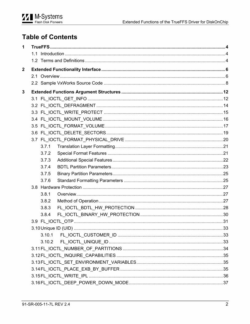
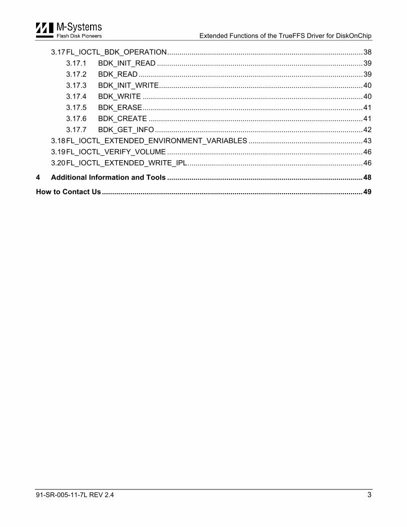
Table of Contents 1 TrueFFS............................................................................................................................................4
1.1 Introduction ................................................................................................................................4 1.2 Terms and Definitions ................................................................................................................4
2 Extended Functionality Interface...................................................................................................6 2.1 Overview ....................................................................................................................................6 2.2 Sample VxWorks Source Code .................................................................................................8
3 Extended Functions Argument Structures .................................................................................12 3.1 FL_IOCTL_GET_INFO ............................................................................................................12 3.2 FL_IOCTL_DEFRAGMENT .....................................................................................................14 3.3 FL_IOCTL_WRITE_PROTECT ...............................................................................................15 3.4 FL_IOCTL_MOUNT_VOLUME................................................................................................16 3.5 FL_IOCTL_FORMAT_VOLUME..............................................................................................17 3.6 FL_IOCTL_DELETE_SECTORS.............................................................................................19 3.7 FL_IOCTL_FORMAT_PHYSICAL_DRIVE ..............................................................................20
3.7.1 Translation Layer Formatting......................................................................................21 3.7.2 Special Format Features ............................................................................................21 3.7.3 Additional Special Features........................................................................................22 3.7.4 BDTL Partition Parameters.........................................................................................23 3.7.5 Binary Partition Parameters........................................................................................25 3.7.6 Standard Formatting Parameters ...............................................................................25
3.8 Hardware Protection ................................................................................................................27 3.8.1 Overview.....................................................................................................................27 3.8.2 Method of Operation...................................................................................................27 3.8.3 FL_IOCTL_BDTL_HW_PROTECTION ......................................................................28 3.8.4 FL_IOCTL_BINARY_HW_PROTECTION..................................................................30
3.9 FL_IOCTL_OTP.......................................................................................................................31 3.10 Unique ID (UID) .......................................................................................................................33
3.10.1 FL_IOCTL_CUSTOMER_ID ....................................................................................33 3.10.2 FL_IOCTL_UNIQUE_ID ...........................................................................................33
3.11 FL_IOCTL_NUMBER_OF_PARTITIONS ................................................................................34 3.12 FL_IOCTL_INQUIRE_CAPABILITIES .....................................................................................35 3.13 FL_IOCTL_SET_ENVIRONMENT_VARIABLES.....................................................................35 3.14 FL_IOCTL_PLACE_EXB_BY_BUFFER ..................................................................................35 3.15 FL_IOCTL_WRITE_IPL ...........................................................................................................36 3.16 FL_IOCTL_DEEP_POWER_DOWN_MODE...........................................................................37
Extended Functions of the TrueFFS Driver for DiskOnChip
91-SR-005-11-7L REV 2.4 3
3.17 FL_IOCTL_BDK_OPERATION................................................................................................38 3.17.1 BDK_INIT_READ .....................................................................................................39 3.17.2 BDK_READ..............................................................................................................39 3.17.3 BDK_INIT_WRITE....................................................................................................40 3.17.4 BDK_WRITE ............................................................................................................40 3.17.5 BDK_ERASE............................................................................................................41 3.17.6 BDK_CREATE .........................................................................................................41 3.17.7 BDK_GET_INFO......................................................................................................42
3.18 FL_IOCTL_EXTENDED_ENVIRONMENT_VARIABLES ........................................................43 3.19 FL_IOCTL_VERIFY_VOLUME ................................................................................................46 3.20 FL_IOCTL_EXTENDED_WRITE_IPL......................................................................................46
4 Additional Information and Tools ................................................................................................48
How to Contact Us................................................................................................................................49
Extended Functions of the TrueFFS Driver for DiskOnChip
91-SR-005-11-7L REV 2.4 4
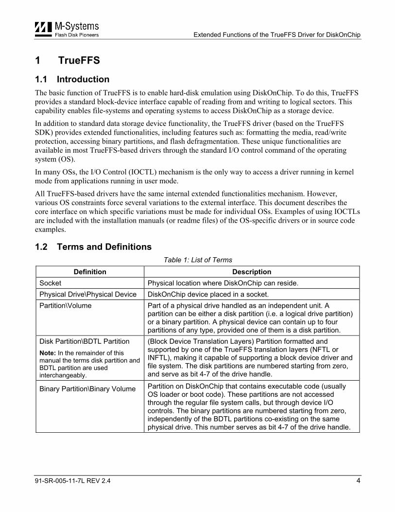
1 TrueFFS
1.1 Introduction The basic function of TrueFFS is to enable hard-disk emulation using DiskOnChip. To do this, TrueFFS provides a standard block-device interface capable of reading from and writing to logical sectors. This capability enables file-systems and operating systems to access DiskOnChip as a storage device.
In addition to standard data storage device functionality, the TrueFFS driver (based on the TrueFFS SDK) provides extended functionalities, including features such as: formatting the media, read/write protection, accessing binary partitions, and flash defragmentation. These unique functionalities are available in most TrueFFS-based drivers through the standard I/O control command of the operating system (OS).
In many OSs, the I/O Control (IOCTL) mechanism is the only way to access a driver running in kernel mode from applications running in user mode.
All TrueFFS-based drivers have the same internal extended functionalities mechanism. However, various OS constraints force several variations to the external interface. This document describes the core interface on which specific variations must be made for individual OSs. Examples of using IOCTLs are included with the installation manuals (or readme files) of the OS-specific drivers or in source code examples.
1.2 Terms and Definitions Table 1: List of Terms
Definition Description Socket Physical location where DiskOnChip can reside. Physical Drive\Physical Device DiskOnChip device placed in a socket. Partition\Volume Part of a physical drive handled as an independent unit. A
partition can be either a disk partition (i.e. a logical drive partition) or a binary partition. A physical device can contain up to four partitions of any type, provided one of them is a disk partition.
Disk Partition\BDTL Partition Note: In the remainder of this manual the terms disk partition and BDTL partition are used interchangeably.
(Block Device Translation Layers) Partition formatted and supported by one of the TrueFFS translation layers (NFTL or INFTL), making it capable of supporting a block device driver and file system. The disk partitions are numbered starting from zero, and serve as bit 4-7 of the drive handle.
Binary Partition\Binary Volume Partition on DiskOnChip that contains executable code (usually OS loader or boot code). These partitions are not accessed through the regular file system calls, but through device I/O controls. The binary partitions are numbered starting from zero, independently of the BDTL partitions co-existing on the same physical drive. This number serves as bit 4-7 of the drive handle.
Extended Functions of the TrueFFS Driver for DiskOnChip
91-SR-005-11-7L REV 2.4 5
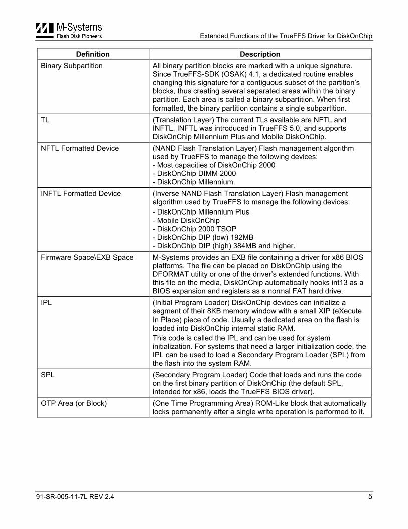
Definition Description Binary Subpartition All binary partition blocks are marked with a unique signature.
Since TrueFFS-SDK (OSAK) 4.1, a dedicated routine enables changing this signature for a contiguous subset of the partition’s blocks, thus creating several separated areas within the binary partition. Each area is called a binary subpartition. When first formatted, the binary partition contains a single subpartition.
TL (Translation Layer) The current TLs available are NFTL and INFTL. INFTL was introduced in TrueFFS 5.0, and supports DiskOnChip Millennium Plus and Mobile DiskOnChip.
NFTL Formatted Device (NAND Flash Translation Layer) Flash management algorithm used by TrueFFS to manage the following devices: - Most capacities of DiskOnChip 2000 - DiskOnChip DIMM 2000 - DiskOnChip Millennium.
INFTL Formatted Device (Inverse NAND Flash Translation Layer) Flash management algorithm used by TrueFFS to manage the following devices: - DiskOnChip Millennium Plus - Mobile DiskOnChip - DiskOnChip 2000 TSOP - DiskOnChip DIP (low) 192MB - DiskOnChip DIP (high) 384MB and higher.
Firmware Space\EXB Space M-Systems provides an EXB file containing a driver for x86 BIOS platforms. The file can be placed on DiskOnChip using the DFORMAT utility or one of the driver’s extended functions. With this file on the media, DiskOnChip automatically hooks int13 as a BIOS expansion and registers as a normal FAT hard drive.
IPL (Initial Program Loader) DiskOnChip devices can initialize a segment of their 8KB memory window with a small XIP (eXecute In Place) piece of code. Usually a dedicated area on the flash is loaded into DiskOnChip internal static RAM. This code is called the IPL and can be used for system initialization. For systems that need a larger initialization code, the IPL can be used to load a Secondary Program Loader (SPL) from the flash into the system RAM.
SPL (Secondary Program Loader) Code that loads and runs the code on the first binary partition of DiskOnChip (the default SPL, intended for x86, loads the TrueFFS BIOS driver).
OTP Area (or Block) (One Time Programming Area) ROM-Like block that automatically locks permanently after a single write operation is performed to it.
Extended Functions of the TrueFFS Driver for DiskOnChip
91-SR-005-11-7L REV 2.4 6
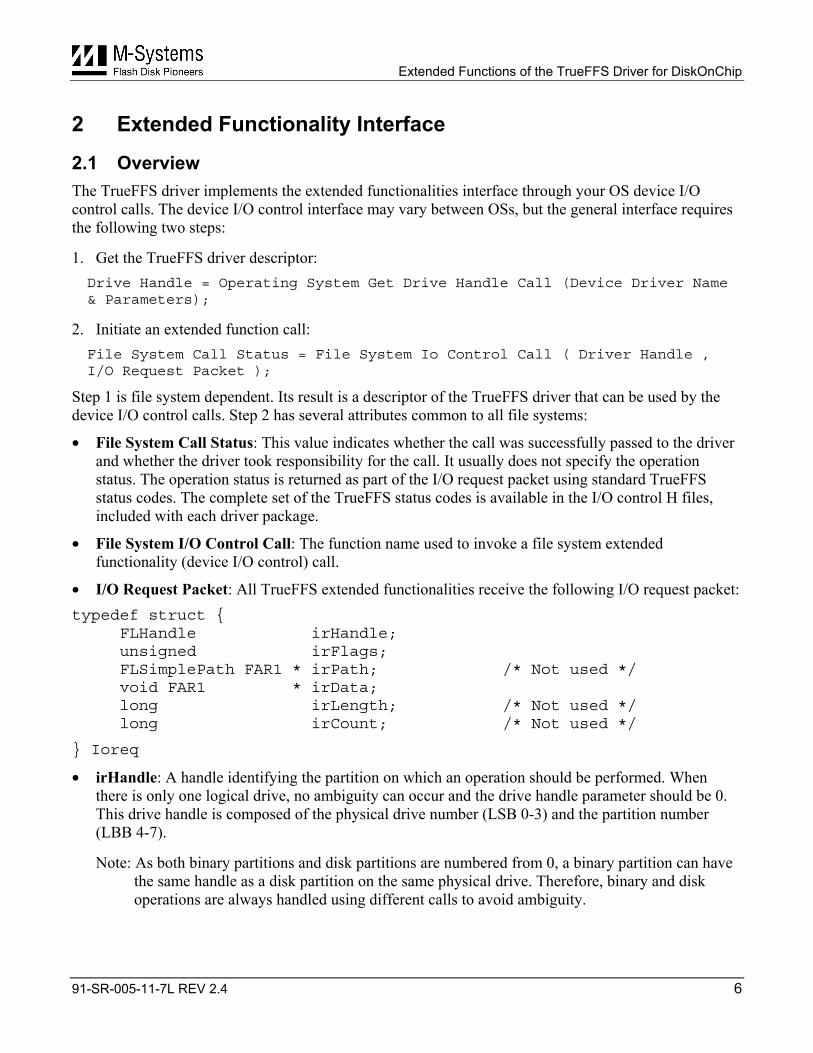
2 Extended Functionality Interface
2.1 Overview The TrueFFS driver implements the extended functionalities interface through your OS device I/O control calls. The device I/O control interface may vary between OSs, but the general interface requires the following two steps:
1. Get the TrueFFS driver descriptor: Drive Handle = Operating System Get Drive Handle Call (Device Driver Name & Parameters);
2. Initiate an extended function call: File System Call Status = File System Io Control Call ( Driver Handle , I/O Request Packet );
Step 1 is file system dependent. Its result is a descriptor of the TrueFFS driver that can be used by the device I/O control calls. Step 2 has several attributes common to all file systems:
• File System Call Status: This value indicates whether the call was successfully passed to the driver and whether the driver took responsibility for the call. It usually does not specify the operation status. The operation status is returned as part of the I/O request packet using standard TrueFFS status codes. The complete set of the TrueFFS status codes is available in the I/O control H files, included with each driver package.
• File System I/O Control Call: The function name used to invoke a file system extended functionality (device I/O control) call.
• I/O Request Packet: All TrueFFS extended functionalities receive the following I/O request packet: typedef struct {
FLHandle irHandle; unsigned irFlags; FLSimplePath FAR1 * irPath; /* Not used */ void FAR1 * irData; long irLength; /* Not used */ long irCount; /* Not used */
} Ioreq
• irHandle: A handle identifying the partition on which an operation should be performed. When there is only one logical drive, no ambiguity can occur and the drive handle parameter should be 0. This drive handle is composed of the physical drive number (LSB 0-3) and the partition number (LBB 4-7).
Note: As both binary partitions and disk partitions are numbered from 0, a binary partition can have the same handle as a disk partition on the same physical drive. Therefore, binary and disk operations are always handled using different calls to avoid ambiguity.
Extended Functions of the TrueFFS Driver for DiskOnChip
91-SR-005-11-7L REV 2.4 7
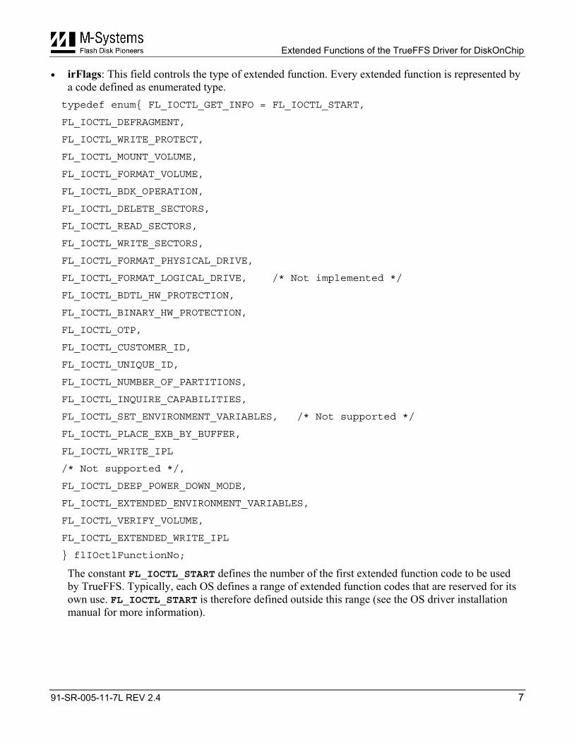
• irFlags: This field controls the type of extended function. Every extended function is represented by a code defined as enumerated type. typedef enum{ FL_IOCTL_GET_INFO = FL_IOCTL_START,
FL_IOCTL_DEFRAGMENT,
FL_IOCTL_WRITE_PROTECT,
FL_IOCTL_MOUNT_VOLUME,
FL_IOCTL_FORMAT_VOLUME,
FL_IOCTL_BDK_OPERATION,
FL_IOCTL_DELETE_SECTORS,
FL_IOCTL_READ_SECTORS,
FL_IOCTL_WRITE_SECTORS,
FL_IOCTL_FORMAT_PHYSICAL_DRIVE,
FL_IOCTL_FORMAT_LOGICAL_DRIVE, /* Not implemented */
FL_IOCTL_BDTL_HW_PROTECTION,
FL_IOCTL_BINARY_HW_PROTECTION,
FL_IOCTL_OTP,
FL_IOCTL_CUSTOMER_ID,
FL_IOCTL_UNIQUE_ID,
FL_IOCTL_NUMBER_OF_PARTITIONS,
FL_IOCTL_INQUIRE_CAPABILITIES,
FL_IOCTL_SET_ENVIRONMENT_VARIABLES, /* Not supported */
FL_IOCTL_PLACE_EXB_BY_BUFFER,
FL_IOCTL_WRITE_IPL
/* Not supported */,
FL_IOCTL_DEEP_POWER_DOWN_MODE,
FL_IOCTL_EXTENDED_ENVIRONMENT_VARIABLES,
FL_IOCTL_VERIFY_VOLUME,
FL_IOCTL_EXTENDED_WRITE_IPL
} flIOctlFunctionNo;
The constant FL_IOCTL_START defines the number of the first extended function code to be used by TrueFFS. Typically, each OS defines a range of extended function codes that are reserved for its own use. FL_IOCTL_START is therefore defined outside this range (see the OS driver installation manual for more information).
Extended Functions of the TrueFFS Driver for DiskOnChip
91-SR-005-11-7L REV 2.4 8
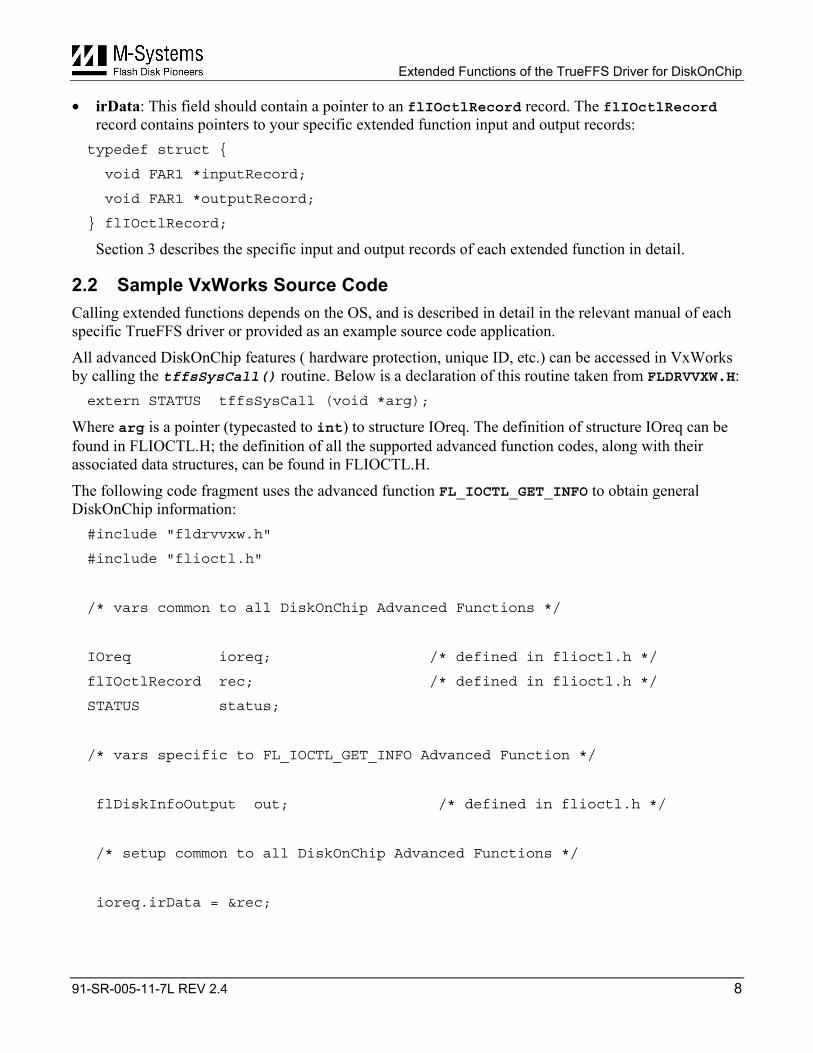
• irData: This field should contain a pointer to an flIOctlRecord record. The flIOctlRecord record contains pointers to your specific extended function input and output records: typedef struct {
void FAR1 *inputRecord;
void FAR1 *outputRecord;
} flIOctlRecord;
Section 3 describes the specific input and output records of each extended function in detail.
2.2 Sample VxWorks Source Code Calling extended functions depends on the OS, and is described in detail in the relevant manual of each specific TrueFFS driver or provided as an example source code application.
All advanced DiskOnChip features ( hardware protection, unique ID, etc.) can be accessed in VxWorks by calling the tffsSysCall() routine. Below is a declaration of this routine taken from FLDRVVXW.H: extern STATUS tffsSysCall (void *arg);
Where arg is a pointer (typecasted to int) to structure IOreq. The definition of structure IOreq can be found in FLIOCTL.H; the definition of all the supported advanced function codes, along with their associated data structures, can be found in FLIOCTL.H.
The following code fragment uses the advanced function FL_IOCTL_GET_INFO to obtain general DiskOnChip information: #include "fldrvvxw.h"
#include "flioctl.h"
/* vars common to all DiskOnChip Advanced Functions */
IOreq ioreq; /* defined in flioctl.h */
flIOctlRecord rec; /* defined in flioctl.h */
STATUS status;
/* vars specific to FL_IOCTL_GET_INFO Advanced Function */
flDiskInfoOutput out; /* defined in flioctl.h */
/* setup common to all DiskOnChip Advanced Functions */
ioreq.irData = &rec;
Extended Functions of the TrueFFS Driver for DiskOnChip
91-SR-005-11-7L REV 2.4 9
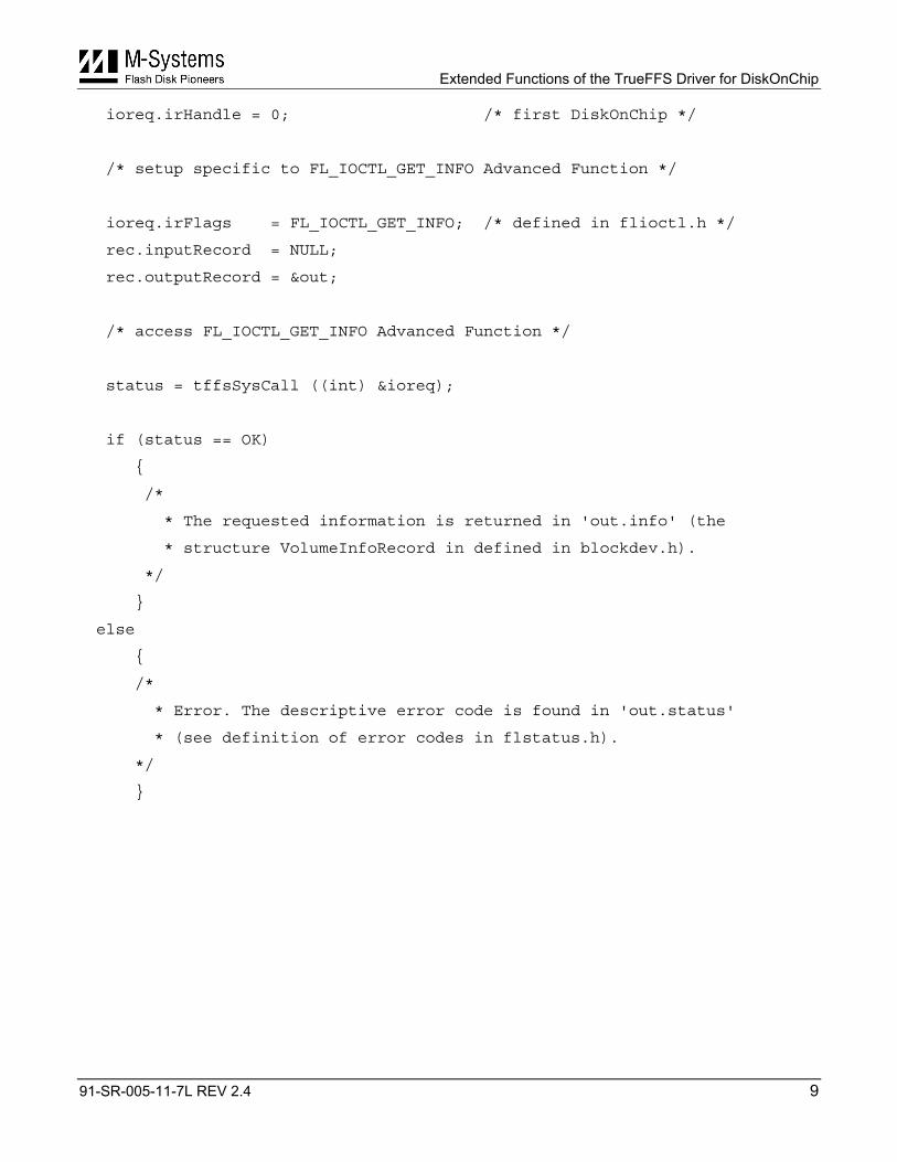
ioreq.irHandle = 0; /* first DiskOnChip */
/* setup specific to FL_IOCTL_GET_INFO Advanced Function */
ioreq.irFlags = FL_IOCTL_GET_INFO; /* defined in flioctl.h */
rec.inputRecord = NULL;
rec.outputRecord = &out;
/* access FL_IOCTL_GET_INFO Advanced Function */
status = tffsSysCall ((int) &ioreq);
if (status == OK)
{
/*
* The requested information is returned in 'out.info' (the
* structure VolumeInfoRecord in defined in blockdev.h).
*/
}
else
{
/*
* Error. The descriptive error code is found in 'out.status'
* (see definition of error codes in flstatus.h).
*/
}
Extended Functions of the TrueFFS Driver for DiskOnChip
91-SR-005-11-7L REV 2.4 10
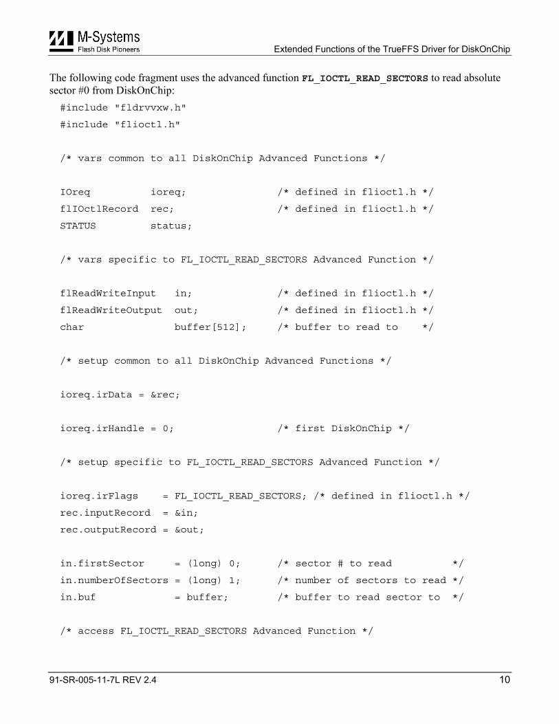
The following code fragment uses the advanced function FL_IOCTL_READ_SECTORS to read absolute sector #0 from DiskOnChip: #include "fldrvvxw.h"
#include "flioctl.h"
/* vars common to all DiskOnChip Advanced Functions */
IOreq ioreq; /* defined in flioctl.h */
flIOctlRecord rec; /* defined in flioctl.h */
STATUS status;
/* vars specific to FL_IOCTL_READ_SECTORS Advanced Function */
flReadWriteInput in; /* defined in flioctl.h */
flReadWriteOutput out; /* defined in flioctl.h */
char buffer[512]; /* buffer to read to */
/* setup common to all DiskOnChip Advanced Functions */
ioreq.irData = &rec;
ioreq.irHandle = 0; /* first DiskOnChip */
/* setup specific to FL_IOCTL_READ_SECTORS Advanced Function */
ioreq.irFlags = FL_IOCTL_READ_SECTORS; /* defined in flioctl.h */
rec.inputRecord = ∈
rec.outputRecord = &out;
in.firstSector = (long) 0; /* sector # to read */
in.numberOfSectors = (long) 1; /* number of sectors to read */
in.buf = buffer; /* buffer to read sector to */
/* access FL_IOCTL_READ_SECTORS Advanced Function */
Extended Functions of the TrueFFS Driver for DiskOnChip
91-SR-005-11-7L REV 2.4 11
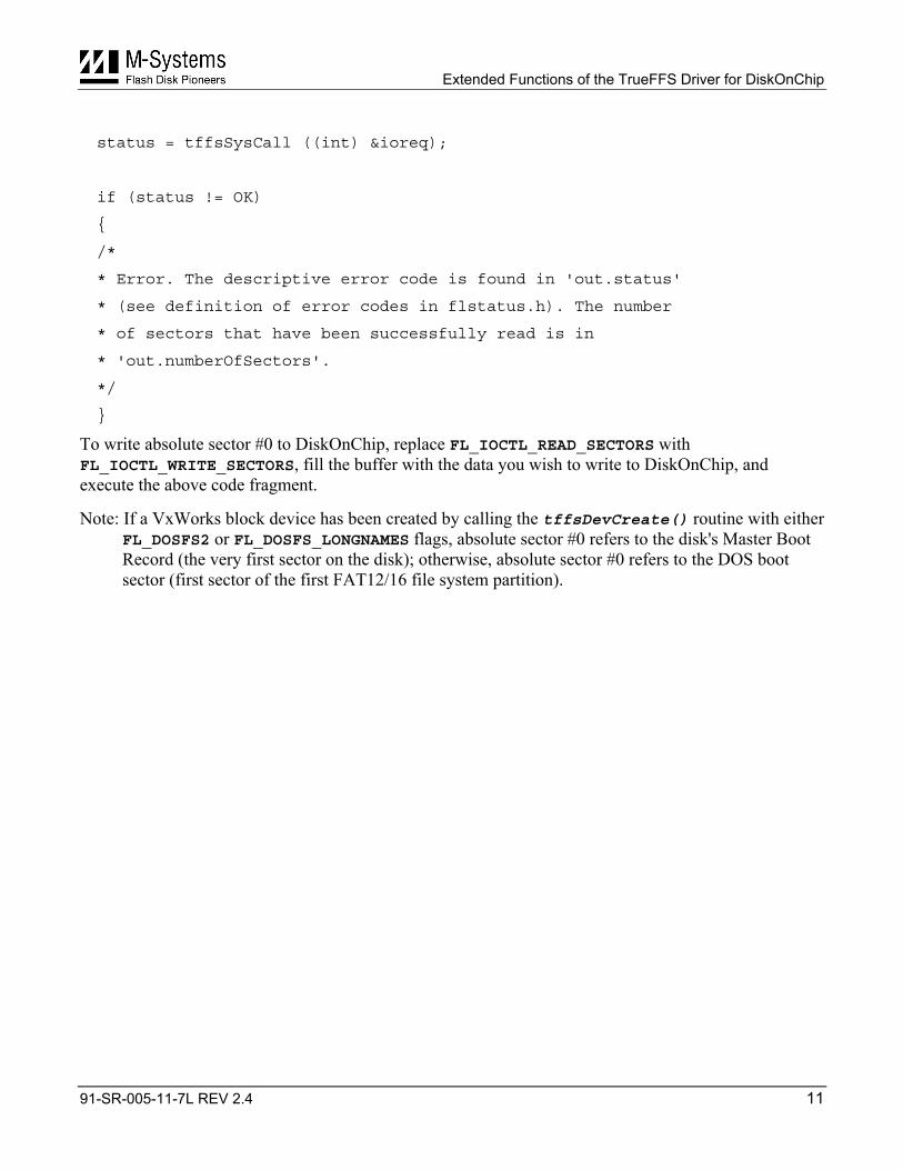
status = tffsSysCall ((int) &ioreq);
if (status != OK)
{
/*
* Error. The descriptive error code is found in 'out.status'
* (see definition of error codes in flstatus.h). The number
* of sectors that have been successfully read is in
* 'out.numberOfSectors'.
*/
}
To write absolute sector #0 to DiskOnChip, replace FL_IOCTL_READ_SECTORS with FL_IOCTL_WRITE_SECTORS, fill the buffer with the data you wish to write to DiskOnChip, and execute the above code fragment.
Note: If a VxWorks block device has been created by calling the tffsDevCreate() routine with either FL_DOSFS2 or FL_DOSFS_LONGNAMES flags, absolute sector #0 refers to the disk's Master Boot Record (the very first sector on the disk); otherwise, absolute sector #0 refers to the DOS boot sector (first sector of the first FAT12/16 file system partition).
Extended Functions of the TrueFFS Driver for DiskOnChip
91-SR-005-11-7L REV 2.4 12
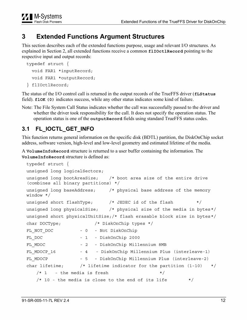
3 Extended Functions Argument Structures This section describes each of the extended functions purpose, usage and relevant I/O structures. As explained in Section 2, all extended functions receive a common flIOctlRecord pointing to the respective input and output records: typedef struct {
void FAR1 *inputRecord;
void FAR1 *outputRecord;
} flIOctlRecord;
The status of the I/O control call is returned in the output records of the TrueFFS driver (fLStatus field). flOK (0) indicates success, while any other status indicates some kind of failure.
Note: The File System Call Status indicates whether the call was successfully passed to the driver and whether the driver took responsibility for the call. It does not specify the operation status. The operation status is one of the outputRecord fields using standard TrueFFS status codes.
3.1 FL_IOCTL_GET_INFO This function returns general information on the specific disk (BDTL) partition, the DiskOnChip socket address, software version, high-level and low-level geometry and estimated lifetime of the media.
A VolumeInfoRecord structure is returned to a user buffer containing the information. The VolumeInfoRecord structure is defined as: typedef struct {
unsigned long logicalSectors;
unsigned long bootAreaSize; /* boot area size of the entire drive (combines all binary partitions) */
unsigned long baseAddress; /* physical base address of the memory window */
unsigned short flashType; /* JEDEC id of the flash */
unsigned long physicalSize; /* physical size of the media in bytes */
unsigned short physicalUnitSize;/* flash erasable block size in bytes */
char DOCType; /* DiskOnChip types */
FL_NOT_DOC - 0 - Not DiskOnChip
FL_DOC - 1 - DiskOnChip 2000
FL_MDOC - 2 - DiskOnChip Millennium 8MB
FL_MDOCP_16 - 4 - DiskOnChip Millennium Plus (interleave-1)
FL_MDOCP - 5 - DiskOnChip Millennium Plus (interleave-2)
char lifetime; /* lifetime indicator for the partition (1-10) */
/* 1 - the media is fresh */
/* 10 - the media is close to the end of its life */
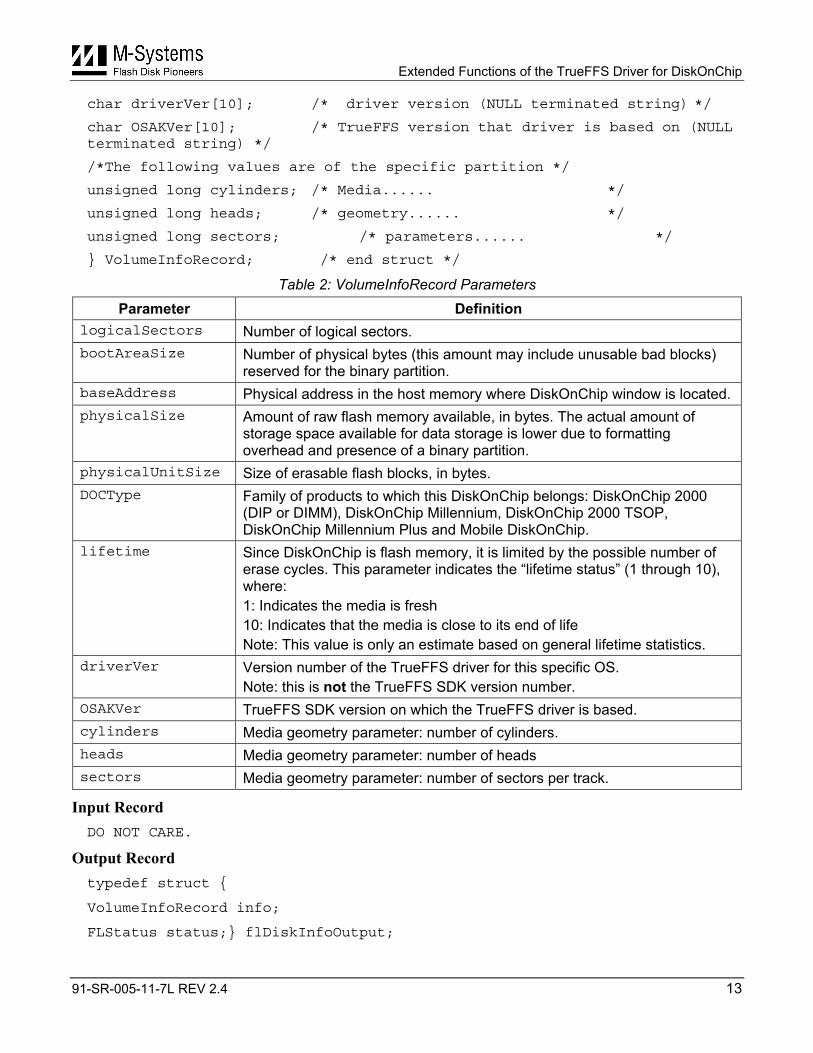
Extended Functions of the TrueFFS Driver for DiskOnChip
91-SR-005-11-7L REV 2.4 13
char driverVer[10]; /* driver version (NULL terminated string) */
char OSAKVer[10]; /* TrueFFS version that driver is based on (NULL terminated string) */
/*The following values are of the specific partition */
unsigned long cylinders; /* Media...... */
unsigned long heads; /* geometry...... */
unsigned long sectors; /* parameters...... */
} VolumeInfoRecord; /* end struct */
Table 2: VolumeInfoRecord Parameters Parameter Definition
logicalSectors Number of logical sectors. bootAreaSize Number of physical bytes (this amount may include unusable bad blocks)
reserved for the binary partition. baseAddress Physical address in the host memory where DiskOnChip window is located. physicalSize Amount of raw flash memory available, in bytes. The actual amount of
storage space available for data storage is lower due to formatting overhead and presence of a binary partition.
physicalUnitSize Size of erasable flash blocks, in bytes. DOCType Family of products to which this DiskOnChip belongs: DiskOnChip 2000
(DIP or DIMM), DiskOnChip Millennium, DiskOnChip 2000 TSOP, DiskOnChip Millennium Plus and Mobile DiskOnChip.
lifetime Since DiskOnChip is flash memory, it is limited by the possible number of erase cycles. This parameter indicates the “lifetime status” (1 through 10), where: 1: Indicates the media is fresh 10: Indicates that the media is close to its end of life Note: This value is only an estimate based on general lifetime statistics.
driverVer Version number of the TrueFFS driver for this specific OS. Note: this is not the TrueFFS SDK version number.
OSAKVer TrueFFS SDK version on which the TrueFFS driver is based. cylinders Media geometry parameter: number of cylinders. heads Media geometry parameter: number of heads sectors Media geometry parameter: number of sectors per track.
Input Record DO NOT CARE.
Output Record typedef struct {
VolumeInfoRecord info;
FLStatus status;} flDiskInfoOutput;
Extended Functions of the TrueFFS Driver for DiskOnChip
91-SR-005-11-7L REV 2.4 14
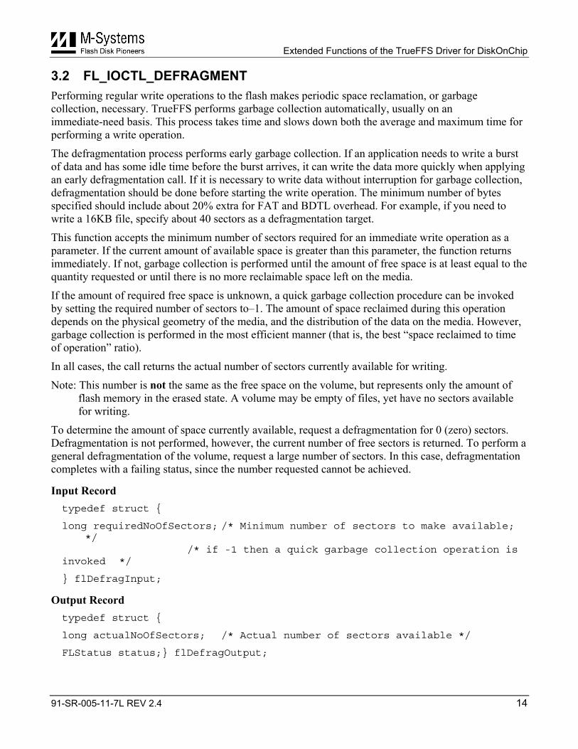
3.2 FL_IOCTL_DEFRAGMENT Performing regular write operations to the flash makes periodic space reclamation, or garbage collection, necessary. TrueFFS performs garbage collection automatically, usually on an immediate-need basis. This process takes time and slows down both the average and maximum time for performing a write operation.
The defragmentation process performs early garbage collection. If an application needs to write a burst of data and has some idle time before the burst arrives, it can write the data more quickly when applying an early defragmentation call. If it is necessary to write data without interruption for garbage collection, defragmentation should be done before starting the write operation. The minimum number of bytes specified should include about 20% extra for FAT and BDTL overhead. For example, if you need to write a 16KB file, specify about 40 sectors as a defragmentation target.
This function accepts the minimum number of sectors required for an immediate write operation as a parameter. If the current amount of available space is greater than this parameter, the function returns immediately. If not, garbage collection is performed until the amount of free space is at least equal to the quantity requested or until there is no more reclaimable space left on the media.
If the amount of required free space is unknown, a quick garbage collection procedure can be invoked by setting the required number of sectors to–1. The amount of space reclaimed during this operation depends on the physical geometry of the media, and the distribution of the data on the media. However, garbage collection is performed in the most efficient manner (that is, the best “space reclaimed to time of operation” ratio).
In all cases, the call returns the actual number of sectors currently available for writing.
Note: This number is not the same as the free space on the volume, but represents only the amount of flash memory in the erased state. A volume may be empty of files, yet have no sectors available for writing.
To determine the amount of space currently available, request a defragmentation for 0 (zero) sectors. Defragmentation is not performed, however, the current number of free sectors is returned. To perform a general defragmentation of the volume, request a large number of sectors. In this case, defragmentation completes with a failing status, since the number requested cannot be achieved.
Input Record typedef struct {
long requiredNoOfSectors; /* Minimum number of sectors to make available; */ /* if -1 then a quick garbage collection operation is invoked */
} flDefragInput;
Output Record typedef struct {
long actualNoOfSectors; /* Actual number of sectors available */
FLStatus status;} flDefragOutput;
Extended Functions of the TrueFFS Driver for DiskOnChip
91-SR-005-11-7L REV 2.4 15
3.3 FL_IOCTL_WRITE_PROTECT This function enables key-controlled write protection (software protection) for DiskOnChip. Once DiskOnChip is protected by the key, it remains in read-only mode. Removing a key can be done by an authorized user who knows the current key.
The key consists of 8 bytes (64 bits), each of which may be any 8-bit code character (264 combinations). The key is stored on the flash disk in a manner that is both scrambled and hidden. That is, the key is encrypted, and it is not possible to read the flash disk to see the encrypted key. If the key is lost or forgotten by the authorized user, the flash disk can be restored to read/write mode by downloading all data from it, reformatting it, and uploading the saved data. A new key can then be enforced.
The same procedure can also be performed by unauthorized users. In this case however, the authorized user is able to determine that the key was removed or changed.
A key-protected DiskOnChip is available to an unauthorized user in read-only mode. All data may be read, but not written or modified. An authorized user can write to the flash disk by temporarily disabling the write-protection (unlock) or permanently removing it (unprotect), depending on the parameters involved. If the protection is temporarily removed, dismounting DiskOnChip and/or performing a system reset cause DiskOnChip to revert to read-only mode.
DiskOnChip units are not key-protected by default when shipped by M-Systems.
Note: This protection is not as reliable as the hardware protection supported by DiskOnChip Millennium Plus and Mobile DiskOnChip.
Input Record typedef struct {
unsigned char type; /* Type of operation: FL_PROTECT / FL_UNPROTECT / FL_UNLOCK */
long password[2]; /* 8 bytes Key */
} flWriteProtectInput
#define FL_PROTECT 0 - Make the DiskOnChip write-protected.
#define FL_UNPROTECT 1 - Permanently remove the write-protection.
#define FL_UNLOCK 2 - Temporarily remove the write-protection.
Output Record typedef struct {
FLStatus status;
} flOutputStatusRecord;
Extended Functions of the TrueFFS Driver for DiskOnChip
91-SR-005-11-7L REV 2.4 16
3.4 FL_IOCTL_MOUNT_VOLUME This function remounts DiskOnChip. Remounting consists of discarding all in-memory control information kept by the TrueFFS driver, and rebuilding it. The remount consists of a low-level BDTL mount.
This function is only required under special circumstances. One of the most common uses of this function is when a user application accesses and modifies DiskOnChip via a method other than the file system or the TrueFFS driver API, such as using the standalone DFORMAT DiskOnChip formatting utility. In this case, the TrueFFS driver is not updated with the changes to DiskOnChip, and every operation becomes unreliable or even harmful. Forcing TrueFFS to remount the driver causes it to get updated with the changes, and enables it to operate reliably.
Input Record typedef struct {
unsigned char type;
} flMountInput;
#define FL_MOUNT 0
#define FL_DISMOUNT 1
Output Record typedef struct {
FLStatus status;
} flOutputStatusRecord;
Note: Invalid arguments will force remounting DiskOnChip (identical to FL_MOUNT).
Extended Functions of the TrueFFS Driver for DiskOnChip
91-SR-005-11-7L REV 2.4 17
3.5 FL_IOCTL_FORMAT_VOLUME This function formats a volume, writing a new and empty file system, and all existing data is destroyed. Optionally, a low-level (flash translation layer) formatting is done. FL_IOCTL_FORMAT_VOLUME is included only for backwards compatibility with previous versions of the TrueFFS SDK. Whenever possible, use FL_IOCTL_FORMAT_PHYSICAL_DRIVE instead.
Input Record typedef struct {
unsigned char formatType; /* Type of format*/
formatParams FAR1 fp; /* Format parameters structure*/
} flFormatInput;
Options for formatType: #define FAT_ONLY_FORMAT 0 - Perform FAT formatting only without the low-level format.
#define TL_FORMAT 1 – Perform both low-level and FAT format.
#define TL_FORMAT_IF_NEEDED 2 – Perform low-level and FAT format only if the current FAT format is invalid.
#define TL_FORMAT_ONLY 8 – Performa low-level format only.
typedef struct
{
/* TL formatting section */
long int bootImageLen;
/* Space to reserve for a boot-image at the start of the
medium. The BDTL volume will begin at the next higher
erase unit boundary */
unsigned int percentUse;
/* The Translation Layer (TL) performance depends on how full the flash media is, becoming slower as the media comes closer to 100% full. It is possible to avoid the worst-case performance (at 100% full) by formatting the media to less than 100% capacity, thus guaranteeing free space at all times. This will sacrifice some capacity. The standard value used is 98 */
unsigned int noOfSpareUnits;
/* BDTL partitions need at least one spare erase unit to function as a read/write media. That unit is normally taken from the transfer units specified by the percentUsed field, but it is possible to specify additional units (which takes more media space). The advantage of
Extended Functions of the TrueFFS Driver for DiskOnChip
91-SR-005-11-7L REV 2.4 18
specifying spare units is that if all the transfer units become bad and inerasable, the spare unit enables TrueFFS to continue its read/write functionality. Conversely, if no spare units are available the media may switch into read-only mode. The standard value used is 1 */
unsigned long vmAddressingLimit; /* NOR flash formatting (not relevant for DiskOnChip)*/
FLStatus (*progressCallback)(int totalUnitsToFormat,int totalUnitsFormattedSoFar);
/* Progress callback routine; will be called if not NULL.
The callback routine is called after erasing each unit,
and its parameters are the total number of erase units
to format and the number erased so far.
The callback routine returns a Status value. A value of
OK (0) allows formatting to continue. Any other value
will abort the formatting with the returned status code. */
/* DOS formatting section */
char volumeId[4];
/* Volume identification number */
char* volumeLabel;
/* Volume label string. If NULL, no label */
unsigned int noOfFATcopies;
/* It is customary to format DOS media with 2 FAT copies.
The first copy is always used, but more copies make it
possible to recover if the FAT becomes corrupted (a
rare occurrence). On the other hand, this slows down
performance and uses media space.
The standard value to use is 2 */
/* NOR flash formatting section (not relevant to DiskOnChip) */
unsigned int embeddedCISlength;
char* embeddedCIS;
}FormatParams;
Extended Functions of the TrueFFS Driver for DiskOnChip
91-SR-005-11-7L REV 2.4 19
Output Record typedef struct {
FLStatus status;
} flOutputStatusRecord;
3.6 FL_IOCTL_DELETE_SECTORS This function marks one or more consecutive absolute sectors as logically deleted, and is required only under special circumstances. TrueFFS write performance depends to some degree on the amount of free space on the flash disk. A flash disk that is close to being full will show slower write performance, as garbage collection must be performed more often.
FL_IOCTL_DELETE_SECTORS is used to increase the amount of logically free space by informing TrueFFS of absolute sectors that it considers used, but can be deleted as they no longer contain useful data.
Typically, FL_IOCTL_DELETE_SECTORS is beneficial for systems that use a non-FAT file system. If the file-system code is available, it is possible to identify the places where the file system marks disk areas as logically deleted, and to inform TrueFFS of this explicitly. In this case, the customer can add a call to the FL_IOCTL_DELETE_SECTORS function after deleting the logical sectors.
Note: This special handling is not necessary when using a FAT file system (sometimes also called a DOS file system), since the TrueFFS driver is automatically aware of space management.
Input Record typedef struct {
long firstSector; /* First logical sector to delete */
long numberOfSectors; /* Number of sectors to delete */
} flDeleteSectorsInput;
Output Record typedef struct {
FLStatus status;
} flOutputStatusRecord;
Extended Functions of the TrueFFS Driver for DiskOnChip
91-SR-005-11-7L REV 2.4 20
3.7 FL_IOCTL_FORMAT_PHYSICAL_DRIVE This function formats DiskOnChip, and supports the full range of functionalities supported by DiskOnChip Millennium Plus and Mobile DiskOnChip. Usage of this IOCTL includes:
• Dividing DiskOnChip into binary partitions and disk (BDTL) partitions.
• Performing a low-level binary format and disk format.
• Protecting up to two partitions of any kind.
• Placing a firmware boot file (or just leaving space for it in the first binary partition).
• Writing an empty FAT file system to disk partitions.
Notes:
Formatting destroys all existing data, and leaves all the disk volumes in the dismounted state, so that a mounting call is necessary afterwards.
DiskOnChip Millennium Plus and Mobile DiskOnChip support up to four partitions of any combination, binary and disk, as long as there is at least one disk partition (other devices support only one disk partition and one binary partition).
All hardware protection keys must be inserted before calling this routine.
Formatting is controlled by a set of parameters defined in a FormatParams2 structure.
Input Record typedef struct {
byte formatType; /* type of format as defined in blockdev.h */
FormatParams2 fp; /* Format parameters structure (defined in flformat.h) */
} flFormatPhysicalInput;
Output Record typedef struct {
FLStatus status;
} flOutputStatusRecord;
Formatting is controlled by a set of parameters defined in a FormatParams2 structure and the flags given to the formatType field.
The FormatParams2 structure is defined in FLFORMAT.H and contains the fields discussed in Section 3.7.1.
Extended Functions of the TrueFFS Driver for DiskOnChip
91-SR-005-11-7L REV 2.4 21
3.7.1 Translation Layer Formatting
byte percentUse; NAND flash inherently contains some bad blocks. TrueFFS handles those blocks by managing a pool of spare blocks, also called transfer units. This format parameter specifies the size of this pool, which is reduced from the total exported media size. According to the flash specifications, 98% should be specified.
byte noOfBDTLPartitions; Indicates the number of disk partitions (1-4). NFTL formatted devices must specify 1.
byte noOfBinaryPartitions; Indicates the number of binary partitions (0-3) to create. If you must keep some or all of your previous binary partitions, refer to the TL_LEAVE_BINARY_AREA and TL_LEAVE_SOME_BINARY_AREA flags of the formatType field in the flFormatPhysicalInput packet. Note that NFTL-formatted devices cannot specify more then one binary partition.
BDTLPartitionFormatParams FAR1* BDTLPartitionInfo;
Disk partition information record array (see definition below).
BinaryPartitionFormatParams FAR1* BinaryPartitionInfo;
An array of binary partition information records (see definition below). This parameter is ignored if the TL_LEAVE_BINARY_AREA flag is set. However, if the TL_LEAVE_SOME_BINARY_AREA is also set, this array describes only the new partitions.
3.7.2 Special Format Features #ifdef WRITE_EXB_IMAGE
The EXB file (firmware file) can be written in one of two ways:
• A single large buffer, containing the entire EXB file, supplied to the format routine through the exbBuffer and exbBufferLen fields.
• Several consecutive calls to the flPlaceExbByBuffer() routine using buffers of any size (provided the first is at least 512 bytes long).
When using the FL_IOCTL_PLACE_EXB_BY_BUFFER extended function, you must ensure that the media is already formatted with a large enough binary subpartition and the SPL signature. To format the media to contain a binary subpartition with the SPL signature, either specify the exact binary subpartition size using the exbLen field, or let the format routine determine the size automatically by setting exbLen to 0 and supplying at least 512 bytes of the EXB file (using the exbBuffer and the exbBufferLen fields). The format routine automatically detects the required size, formats the media with the required space and places the part of the EXB file that was already provided. The rest of the EXB buffer can be supplied using consecutive calls to the FL_IOCTL_PLACE_EXB_BY_BUFFER extended function.
Extended Functions of the TrueFFS Driver for DiskOnChip
91-SR-005-11-7L REV 2.4 22
void FAR1* exbBuffer; Pointer to the user buffer containing the EXB file. If no EXB
should be written, set the field to NULL. dword exbBufferLen; Size of the user buffer containing the EXB file. dword exbLen; Specify the media size to set aside for the EXB file (a 0 value
disables both the exbBuffer and exbBufferLen fields and automatic detection of the required buffer size).
word exbWindow; Specify the DiskOnChip memory base address for the BIOS driver (set a 0 value for automatic detection of the address where the IPL code resides).
byte exbFlags; EXB-specific flags (see the FL_IOCTL_PLACE_EXB_ BY_BUFFER extended function for the full flag list).
#endif /* WRITE_EXB_IMAGE */
byte cascadedDeviceNo; Reserved. byte noOfCascadedDevices; Reserved. FLStatus (*progressCallback)
(word totalUnitsToFormat, word totalUnitsFormattedSoFar);
Pointer to a user-defined progress callback routine. If no callback routine is necessary, set the progressCallBack field to NULL. The callback routine should return a status value. A value of flOK (0) allows formatting to continue, while any other value aborts the formatting. TrueFFS calls this routine while it formats the media. The first argument indicates the total number of units in the media, while the second indicates the currently formatted unit number.
If the FL_REPORT_MOUNT_FEATURE compilation flag is set, the format routine indicates the beginning of the mount of each device partition by returning both callback routine arguments as 0. It also reports the progress of the mount routine. The first argument indicates the number of units in the partitions, and the second indicates the currently mounted unit. Note that a disk partition may contain more units then it exports.
3.7.3 Additional Special Features The following fields are part of the extended function features, but are not used for DiskOnChip devices: dword vmAddressingLimit; Reserved for none-DiskOnChip devices.. word embeddedCISlength; Reserved for none-DiskOnChip devices. byte FAR1 * embeddedCIS; Reserved for none-DiskOnChip devices.
Both the disk and the binary partition parameters are passed through arrays of dedicated parameter records.
Extended Functions of the TrueFFS Driver for DiskOnChip
91-SR-005-11-7L REV 2.4 23
3.7.4 BDTL Partition Parameters BDTL partition parameters are passed through the BDTLPartitionInfo field. This field is an array of BDTLPartitionFormatParams structures defined in FLFORMAT.H with the following fields: dword partitionSize; The size of the usable storage space, in bytes. The size is rounded
upwards to a multiple of an erasable unit size. The size of the last partition is automatically calculated and that parameter is ignored. Requesting a size smaller then an erasable unit for any partition except the last will return an flBadParameters error code.
unsigned noOfSpareUnits; Disk partitions need at least one spare erase unit to function as a write-able media, and at least two to be fully protected against power failures. Spare erase units are normally taken from the transfer units specified by the percentUsed field, but it is possible to specify additional units (which takes more media space). This ensures that if all the transfer units become bad and/or inerasable, the spare unit enables TrueFFS to maintain its read/write functionality. Conversely, if no spare units are available, the media may switch to read-only mode. The standard value used is 2.
byte flag; Any of the following flags: TL_NORMAL_FORMAT Format the media without placing any type of higher-level
formatting. TL_FORMAT_FAT Format the media with basic FAT format. TL_OLD_FORMAT Format the media with basic FAT format assuming one sector per
cluster. Byte volumeId[4]; DOS partition identification number. byte FAR1 * volumeLabel; DOS partition label string. If NULL, no label. byte noOfFATcopies; It is customary to format DOS media with two FAT copies. The
first copy is always used, but the additional copy makes it possible to recover the FAT if it becomes corrupted (a rare occurrence). However, this slows down performance and uses media space. The standard value used is 2.
#ifdef HW_PROTECTION
byte ProtectionKey[8]; The key for the protection. byte ProtectionType; A combination of the following flags:
PROTECTABLE This partition can receive protection attributes. READ_PROTECTED Protected against read operations. WRITE_PROTECTED Protected against write operations.
Extended Functions of the TrueFFS Driver for DiskOnChip
91-SR-005-11-7L REV 2.4 24
LOCK_ENABLED Enables the hardware lock signal. CHANGEABLE_PROTECTION This partition protection is changeable after format.
More information regarding protection attributes can be found in Section 3.8. #endif /* HW_PROTECTION */
Extended Functions of the TrueFFS Driver for DiskOnChip
91-SR-005-11-7L REV 2.4 25
3.7.5 Binary Partition Parameters Binary partition parameters are passed through the binaryPartitionInfo field. This field is an array of BinaryPartitionFormatParams structures defined in FLFORMAT.H, as follows: Dword length; The size of the usable storage space, in bytes (not counting bad
blocks). The size is rounded upwards to a multiple of an erasable unit size. Requesting a size smaller then an erasable unit for any binary partition will return an flBadParameters error code.
byte Sign[4]; Signature of the binary partition to format. Valid values are 0x0000 0000 to 0xFFFF FFFE.
byte signOffset; Offset of the signature. This value should always be 8, but it can also accept 0 for backward compatibility reasons. Note that if the offset is 0, EDC\ECC is disabled.
#ifdef HW_PROTECTION
byte ProtectionKey[8]; The key for the protection. byte ProtectionType; The same flags as in the disk partition structure above. #endif /* HW_PROTECTION */
3.7.6 Standard Formatting Parameters You can use the STD_FORMAT_PARAMS2 definition to initialize the FormatParams2 record. These values reformat the media without modifying the binary partitions or the EXB file. A single unprotected disk partition is created in the remaining area of the volume, with two FAT copies, a volume ID of 0000, no volume label, two spare units and 98% usage. If the previous binary partition cannot be detected (unformatted media), no binary partition is created.
STD_FORMAT_PARAMS2 is defined in FLFORMAT.H with the following values: 98, percentUse
1, numberOfBDTLPartitions
0, numberOfBinaryPartitions
NULL BDTLPartitionInfo
NULL, binaryPartitionInfo
#ifdef WRITE_EXB_IMAGE
NULL, exbBuffer
0, exbBuffeLen
0, exbLen
0, windowBase
0, exbFlags
#endif /* WRITE_EXB_IMAGE */
0, cascadedDeviceNo.
0, noOfCascadedDevices
Extended Functions of the TrueFFS Driver for DiskOnChip
91-SR-005-11-7L REV 2.4 26
NULL, ProgressCallback
0x10000l, vmAddressLimit for backwards compatibility
0, embeddedCISLength
NULL embeddedCIS
In addition to the above standard format parameters, you should initialize the BDTLPartitionInfo field describing the disk partition attributes (BDTLPartitionFormatParams record). Use the standard values STD_BDTL_PARAMS, which are also defined in FLFORMAT.H. 0, partitionSize
1, noOfSpareUnits
TL_FORMAT_FAT , flags
{0,0,0,0}, volumeId[4]
NULL, volumeLabel
2, noOfFATcopies
#ifdef HW_PROTECTION
{0,0,0,0,0,0,0,0} protectionKey[8]
0, protectionType
#endif /* HW_PROTECTION /
The formatType field can have one of the following values: TL_NORMAL_FORMAT Do not leave previous binary partitions. TL_LEAVE_BINARY_AREA Ignores all the binary partitions and firmware arguments of
the function and leaves the data in those areas as is. TL_LEAVE_SOME_BINARY_AREA Ignores the firmware arguments, but allows you to leave
only some of the previous binary partitions, while creating some new ones. The number of binary partition to leave is indicated by the irLength flag of the IOreq packet, while the numberOfBinaryPartitions field indicates the number of new partitions to create.
Note that this flag contains all of the TL_LEAVE_BINARY_AREA flag bits.
Extended Functions of the TrueFFS Driver for DiskOnChip
91-SR-005-11-7L REV 2.4 27
3.8 Hardware Protection
3.8.1 Overview The extended functionality calls described in this section perform hardware read/write protection related operations, and consequently can be used only with DiskOnChip devices that have the required hardware support (currently DiskOnChip Millennium Plus and Mobile DiskOnChip).
There are different functions for handling binary and disk partitions. Their usage is identical, the only difference being that disk partitions require the FL_IOCTL_BDTL_HW_PROTECTION function while binary partitions require the FL_IOCTL_BINARY_HW_PROTECTION function.
3.8.2 Method of Operation Mobile DiskOnChip and DiskOnChip Millennium Plus enable you to define two partitions that are key protected (in hardware) against any combination of read or write operations. Defining their size and protection attributes (read/write/changeable/lock) is done at the media formatting stage, using the DFORMAT utility or format extended function call. You may define one partition as changeable, meaning that its password and attributes are fully configurable (read/write, both, none and vice versa) at any time. Note that unchangeable partition attributes (including the protection key) cannot be changed unless the media is reformatted.
Mobile DiskOnChip and DiskOnChip Millennium Plus have an additional hardware safety mechanism. If the Lock option is enabled (using one of the extended functions), and the DiskOnChip LOCK pin/ball is set, then the protected partition has an additional hardware lock preventing the use of the key. This means that not even using the correct key will provide access to the protected partitions.
A good analogy for how DiskOnChip hardware protection works would be the following:
You can decide whether or not to install a lock on your door (this is done at the DFORMAT stage) and whether you want to add a safety chain to it (LOCK-enabled). However, at any given point in time you can decide whether to leave the “key” inside (insert key) to allow free access or to remove the key, leaving the door closed. No protection violation operation can be performed without inserting the key. If you installed a safety chain on your door, you can always use it (assert the DiskOnChip hardware LOCK pin/ball) to prevent access even if someone has the correct key or even if the key is currently inserted. If the safety chain was not installed during the format stage (or later on when the partition is changeable) then the DiskOnChip LOCK pin/ball is ignored by the hardware protection logic.
Note: The target volume does not have to be mounted before calling a hardware protection routine, and is not affected by the dismount process.
Each protected partition has its own unique attributes: key, read\write protection and the hardware LOCK signal enable state (the safety chain). TrueFFS exports several routines that enable changing these attributes: change key, change protection type (read\write protected) and change hardware LOCK state (enabled or not).
A change of any of these attributes causes a reset of the protection mechanism, and consequently, the removal of all the devices protection keys. Care should be taken to avoid interference between different protected partitions. For example, a key inserted into one partition will be removed when another partition is instructed to change its protection attributes (for example, changing the key).
Extended Functions of the TrueFFS Driver for DiskOnChip
91-SR-005-11-7L REV 2.4 28
The only way to write or read to/from a read- or write-protected partition is to use the insert key call (not even reformatting will remove the protection). This is also true for modifying its attributes (key, read, write and Lock Enable state). The key is removed in each one of the following events: • Power down. • Change to one of the protection attributes (not necessarily to the same partition). • Write operation to the IPL area using the FL_IOCTL_WRITE_IPL function. • Removal of the protection key via the TrueFFS API.
Notes:
In order to make a partition changeable, the specific flag must be added to the protectionType field in the format record. Without this flag, executing functions to change protection attributes will return error codes.
If the partition is protected and the LOCK pin is asserted and enabled, there is no way to remove the protection via software (not even using the disable lock call). The DiskOnChip LOCK pin must be negated first.
Only one partition per device can have changeable status.
3.8.3 FL_IOCTL_BDTL_HW_PROTECTION The functions described in this section perform standard operations on partitions protected by the DiskOnChip hardware. Not all M-Systems devices support this feature. To find out, call the FL_IOCTL_INQUIRE_CAPABILITIES function with the SUPPORT_OTP_AREA option (see Section 3.12). The hardware protection extended function is divided into subfunctions. All of the subfunctions use the same record for input and output.
Input Record typedef struct {
unsigned char protectionType;/* See PROTECTION_GET_TYPE table bellow */
unsigned char key[8]; /* The key */
Unsigned char type; /* One of the following flags: */
#define PROTECTION_INSERT_KEY - 0 - Insert key (disabling protection)
#define PROTECTION_REMOVE_KEY - 1 - Remov key (restoring protection)
#define PROTECTION_DISABLE_LOCK - 2 - Do not enable the H/W LOCK pin
#define PROTECTION_ENABLE_LOCK - 3 - Enable the H/W LOCK pin
#define PROTECTION_GET_TYPE - 4 - Get the current protection status
#define PROTECTION_CHANGE_KEY - 5 - Change the protection key
#define PROTECTION_CHANGE_ TYPE - 6 - Change the protection type (read \ write protected)
} flProtectionInput;
Extended Functions of the TrueFFS Driver for DiskOnChip
91-SR-005-11-7L REV 2.4 29
Output Record typedef struct {
FLStatus status;
} flOutputStatusRecord;
Note: Some protection operations return values in the flProtectionInput record.
Following are the action types and required arguments in the flProtectionInput record:
PROTECTION_INSERT_KEY: Inserts the key to a protected area. flProtectionInput Parameters Key The key to be inserted.
Note: Inserting a wrong key to a partition that already has a key inserted does not fail.
PROTECTION_REMOVE_KEY: Removes the key from a protected partition.
PROTECTION_DISABLE_LOCK: Disables the DiskOnChip LOCK pin signal effect on the key.
PROTECTION_ENABLE_LOCK: Enables the DiskOnChip LOCK pin signal effect on the key.
PROTECTION_CHANGE_KEY: Change the key of a protected partition. flProtectionInput Parameters Key The new key for the protection area.
CHANGE_PROTECTION_TYPE: Changes the protection type. flProtectionInput Parameters
PROTECTABLE 1 Must be added for the operation to succeed. READ_PROTECTED 2 Partition is protected against read operations.
ProtectionType
WRITE_PROTECTED 4 Partition is protected against write operations.
Extended Functions of the TrueFFS Driver for DiskOnChip
91-SR-005-11-7L REV 2.4 30
PROTECTION_GET_TYPE: Gets a protected partition status. flProtectionInput Parameters type Action type.
PROTECTABLE 1 Partition can be protected. READ_PROTECTED 2 Partition is protected against read
operations. WRITE_PROTECTED 4 Partition is protected against write
operations. LOCK_ENABLED 8 Hardware LOCK signal is enabled. LOCK_ASSERTED 16 Hardware LOCK signal is currently asserted.KEY_INSERTED 32 Protection is temporarily removed.
protectionType
CHANGEABLE_PROTECTION 64 Partition protection attributes can be changed without fully reformatting the media.
Returns Status flOK: Success.
flNotProtected: Not a protected partition.
3.8.4 FL_IOCTL_BINARY_HW_PROTECTION This extended function is identical to the FL_IOCTL_BDTL_HW_PROTECTION function, but is used exclusively for binary partitions.
Extended Functions of the TrueFFS Driver for DiskOnChip
91-SR-005-11-7L REV 2.4 31
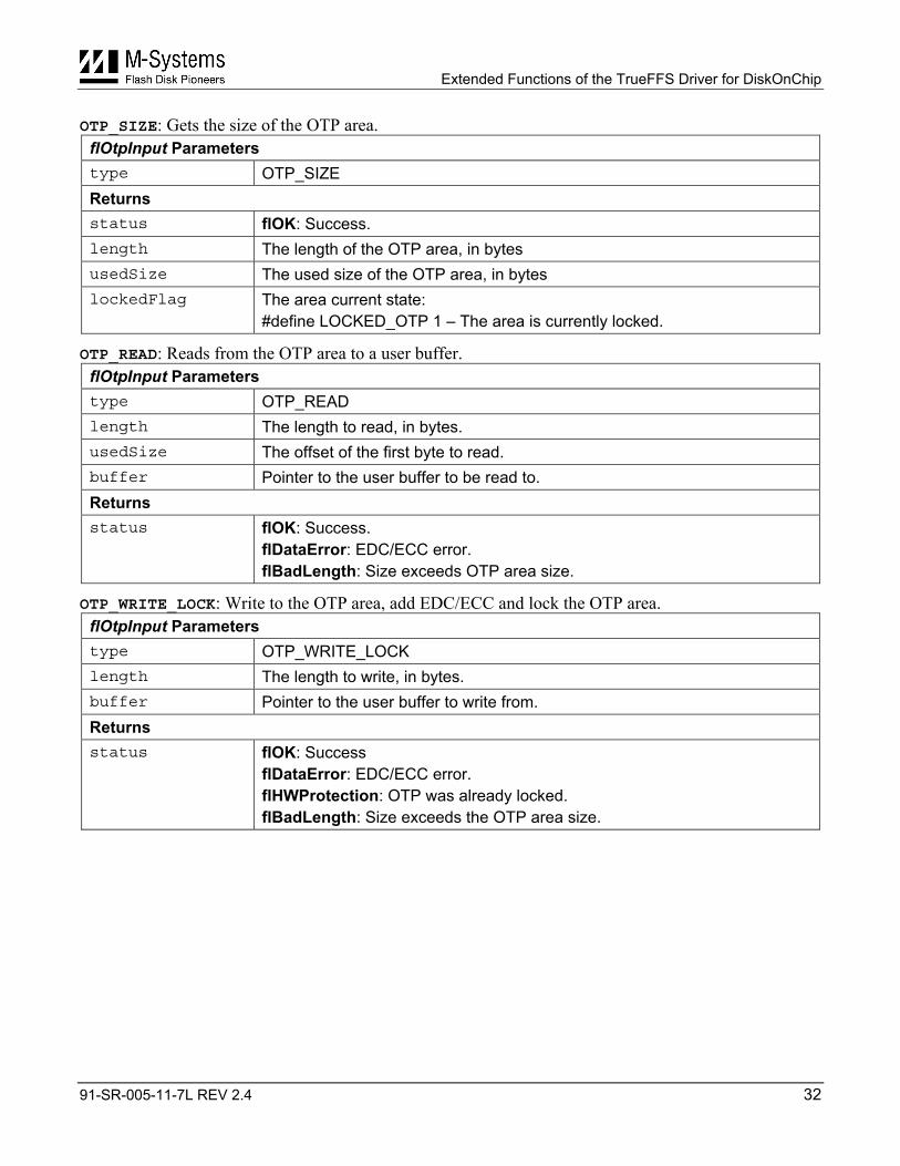
3.9 FL_IOCTL_OTP The functions described in this section perform standard operations on the One Time Programmable (OTP) area. Not all M-Systems devices support this feature. To determine if your DiskOnChip supports the OTP area, call the FL_IOCTL_INQUIRE_CAPABILITIES function with the SUPPORT_OTP_AREA option (see Section 3.12). Mobile DiskOnChip and DiskOnChip Millennium Plus have a ROM-like hardware feature called an OTP area. This feature provides a dedicated area on the flash that is written to once and then locked permanently by the DiskOnChip hardware. After the first write to the OTP area, (EDC is automatically added) it is hardware-protected against all write and erase operations. The total size of the area, the actual used size and the locked state can be retrieved in addition to performing normal read operations of the area.
The OTP extended function is divided into subfunctions. A pointer to the flOtpInput structure is passed to all of the OTP subfunctions. The same record is sent both as input and as output.
Input Record typedef struct {
unsigned long length; /* Length to read/write/size in bytes */
unsigned long usedSize; /* The written size of the area in bytes */
unsigned char lockedFlag; /* The area condition (LOCKED_OTP) */
unsigned char FAR1* buffer; /* pointer to user buffer */
word type; /* One of the types bellow */
} flOtpInput; /* flOtpOutput is the same */
#define OTP_SIZE 1 - Get OTP statistics.
#define OTP_READ 2 – Read from the OTP area.
#define OTP_WRITE_LOCK 3 - Write and permanently lock the OTP area.
Output Record typedef struct {
FLStatus status;
} flOutputStatusRecord;
Extended Functions of the TrueFFS Driver for DiskOnChip
91-SR-005-11-7L REV 2.4 32
OTP_SIZE: Gets the size of the OTP area. flOtpInput Parameters type OTP_SIZE Returns status flOK: Success. length The length of the OTP area, in bytes usedSize The used size of the OTP area, in bytes lockedFlag The area current state:
#define LOCKED_OTP 1 – The area is currently locked.
OTP_READ: Reads from the OTP area to a user buffer. flOtpInput Parameters type OTP_READ length The length to read, in bytes. usedSize The offset of the first byte to read. buffer Pointer to the user buffer to be read to. Returns status flOK: Success.
flDataError: EDC/ECC error. flBadLength: Size exceeds OTP area size.
OTP_WRITE_LOCK: Write to the OTP area, add EDC/ECC and lock the OTP area. flOtpInput Parameters type OTP_WRITE_LOCK length The length to write, in bytes. buffer Pointer to the user buffer to write from. Returns status flOK: Success
flDataError: EDC/ECC error. flHWProtection: OTP was already locked. flBadLength: Size exceeds the OTP area size.
Extended Functions of the TrueFFS Driver for DiskOnChip
91-SR-005-11-7L REV 2.4 33
3.10 Unique ID (UID) The functions described in this section perform standard operations on the ID region of DiskOnChip.
Each Mobile DiskOnChip and DiskOnChip Millennium Plus device has a unique 16-byte ID number, called a Unique ID (UID). This number is randomly generated and guaranteed to be unique to this DiskOnChip device, meaning that no two units are the same. When ordering large quantities of DiskOnChip, a 4-byte customer ID signature can be burned into the units (at the FAB stage). Both IDs are hardware protected against write and erase operations.
3.10.1 FL_IOCTL_CUSTOMER_ID Returns the hardware-embedded 4-byte customer ID information.
Input Record DO NOT CARE
Output Record {
unsigned char id[4] ;
FLStatus status;
} flCustomerIdOutput;
3.10.2 FL_IOCTL_UNIQUE_ID Returns the hardware-embedded 16-byte UID information.
Input Record DO NOT CARE
Output Record {
unsigned char id[16] ;
FLStatus status;
} flJUniqueIdOutput;
Extended Functions of the TrueFFS Driver for DiskOnChip
91-SR-005-11-7L REV 2.4 34
3.11 FL_IOCTL_NUMBER_OF_PARTITIONS Returns the number of disk partitions in a specified device.
Input Record DO NOT CARE
Output Record typedef struct {
unsigned char noOfPartitions;
FLStatus status;
} flCountPartitionsOutput;
Extended Functions of the TrueFFS Driver for DiskOnChip
91-SR-005-11-7L REV 2.4 35
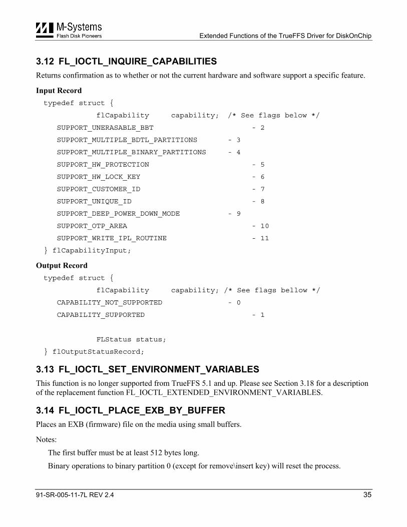
3.12 FL_IOCTL_INQUIRE_CAPABILITIES Returns confirmation as to whether or not the current hardware and software support a specific feature.
Input Record typedef struct {
flCapability capability; /* See flags below */
SUPPORT_UNERASABLE_BBT - 2
SUPPORT_MULTIPLE_BDTL_PARTITIONS - 3
SUPPORT_MULTIPLE_BINARY_PARTITIONS - 4
SUPPORT_HW_PROTECTION - 5
SUPPORT_HW_LOCK_KEY - 6
SUPPORT_CUSTOMER_ID - 7
SUPPORT_UNIQUE_ID - 8
SUPPORT_DEEP_POWER_DOWN_MODE - 9
SUPPORT_OTP_AREA - 10
SUPPORT_WRITE_IPL_ROUTINE - 11
} flCapabilityInput;
Output Record typedef struct {
flCapability capability; /* See flags bellow */
CAPABILITY_NOT_SUPPORTED - 0
CAPABILITY_SUPPORTED - 1
FLStatus status;
} flOutputStatusRecord;
3.13 FL_IOCTL_SET_ENVIRONMENT_VARIABLES This function is no longer supported from TrueFFS 5.1 and up. Please see Section 3.18 for a description of the replacement function FL_IOCTL_EXTENDED_ENVIRONMENT_VARIABLES.
3.14 FL_IOCTL_PLACE_EXB_BY_BUFFER Places an EXB (firmware) file on the media using small buffers.
Notes:
The first buffer must be at least 512 bytes long.
Binary operations to binary partition 0 (except for remove\insert key) will reset the process.

Extended Functions of the TrueFFS Driver for DiskOnChip
91-SR-005-11-7L REV 2.4 36
Only M-Systems EXB files are supported by this routine.
Calling this routine with a partition number other than 0 returns an flBadDriveHandle error code.
Input Record typedef struct {
byteFAR1* buf; /* Buffer of EXB file */
unsigned long bufLen; /* Buffer length */
unsigned short exbWindow /* Explicitly set device window. 0 will automatically set window */
byte exbFlags /* A combination of EXB flags see bellow: */
} flPlaceExbInput;
INSTALL_FIRST 1 Make the device the first hard drive. QUIET 4 Do not show titles while BIOS expansion is found. INT15_DISABLE 8 Disable INT15 hooking. FLOPPY 16 Make device assume drive A: (This will not make it bootable). SIS5598 32 Support Windows NT platforms with SIS5598 VGA chipset. EBDA_SUPPORT 64 Support BIOS with EBDA. NO_PNP_HEADER 128 Do not place the PNP header.
exbFlags
LEAVE_EMPTY 256 Leave the firmware area empty.
Output Record typedef struct {
FLStatus status;
} flOutputStatusRecord;
3.15 FL_IOCTL_WRITE_IPL This function is no longer supported from TrueFFS 5.1 and up. Please see Section 3.20 for a description of the replacement function FL_IOCTL_EXTENDED_WRITE_IPL.
Extended Functions of the TrueFFS Driver for DiskOnChip
91-SR-005-11-7L REV 2.4 37
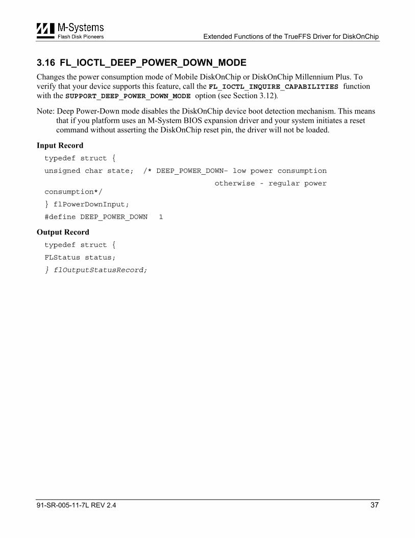
3.16 FL_IOCTL_DEEP_POWER_DOWN_MODE Changes the power consumption mode of Mobile DiskOnChip or DiskOnChip Millennium Plus. To verify that your device supports this feature, call the FL_IOCTL_INQUIRE_CAPABILITIES function with the SUPPORT_DEEP_POWER_DOWN_MODE option (see Section 3.12).
Note: Deep Power-Down mode disables the DiskOnChip device boot detection mechanism. This means that if you platform uses an M-System BIOS expansion driver and your system initiates a reset command without asserting the DiskOnChip reset pin, the driver will not be loaded.
Input Record typedef struct {
unsigned char state; /* DEEP_POWER_DOWN– low power consumption
otherwise - regular power consumption*/
} flPowerDownInput;
#define DEEP_POWER_DOWN 1
Output Record typedef struct {
FLStatus status;
} flOutputStatusRecord;
Extended Functions of the TrueFFS Driver for DiskOnChip
91-SR-005-11-7L REV 2.4 38
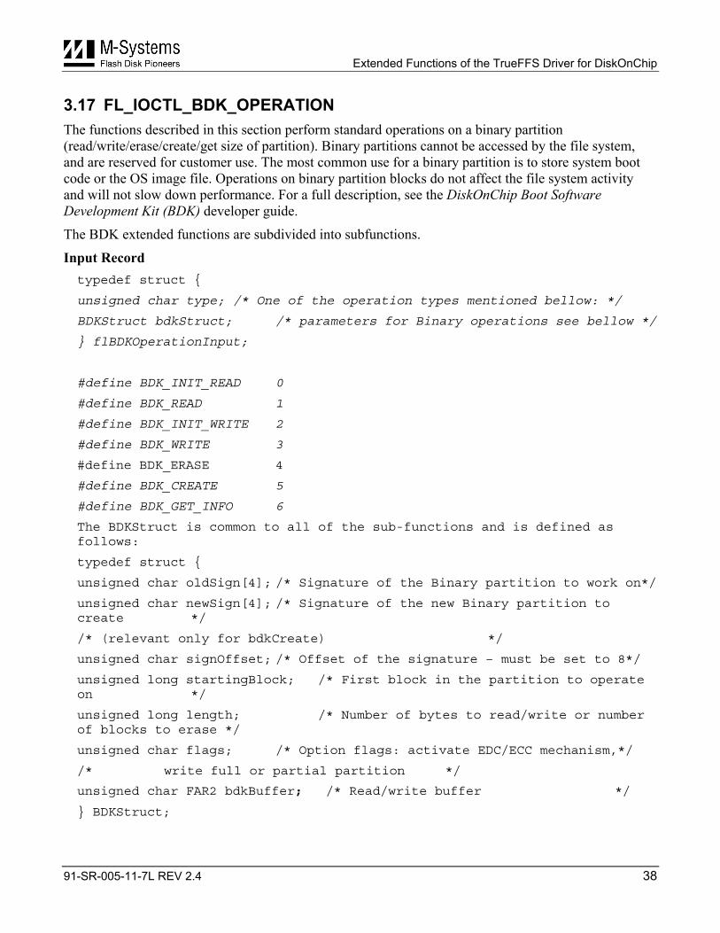
3.17 FL_IOCTL_BDK_OPERATION The functions described in this section perform standard operations on a binary partition (read/write/erase/create/get size of partition). Binary partitions cannot be accessed by the file system, and are reserved for customer use. The most common use for a binary partition is to store system boot code or the OS image file. Operations on binary partition blocks do not affect the file system activity and will not slow down performance. For a full description, see the DiskOnChip Boot Software Development Kit (BDK) developer guide.
The BDK extended functions are subdivided into subfunctions.
Input Record typedef struct {
unsigned char type; /* One of the operation types mentioned bellow: */
BDKStruct bdkStruct; /* parameters for Binary operations see bellow */
} flBDKOperationInput;
#define BDK_INIT_READ 0
#define BDK_READ 1
#define BDK_INIT_WRITE 2
#define BDK_WRITE 3
#define BDK_ERASE 4
#define BDK_CREATE 5
#define BDK_GET_INFO 6
The BDKStruct is common to all of the sub-functions and is defined as follows:
typedef struct {
unsigned char oldSign[4]; /* Signature of the Binary partition to work on*/
unsigned char newSign[4]; /* Signature of the new Binary partition to create */
/* (relevant only for bdkCreate) */
unsigned char signOffset; /* Offset of the signature – must be set to 8*/
unsigned long startingBlock; /* First block in the partition to operate on */
unsigned long length; /* Number of bytes to read/write or number of blocks to erase */
unsigned char flags; /* Option flags: activate EDC/ECC mechanism,*/
/* write full or partial partition */
unsigned char FAR2 bdkBuffer; /* Read/write buffer */
} BDKStruct;
Extended Functions of the TrueFFS Driver for DiskOnChip
91-SR-005-11-7L REV 2.4 39
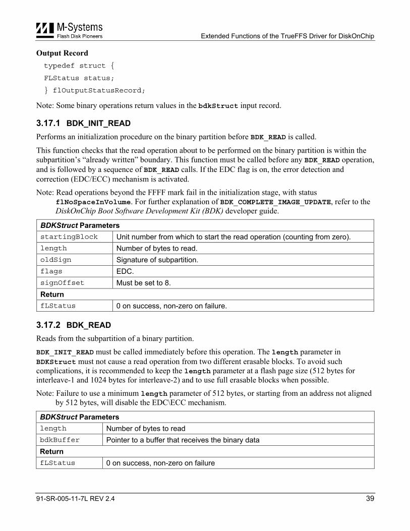
Output Record typedef struct {
FLStatus status;
} flOutputStatusRecord;
Note: Some binary operations return values in the bdkStruct input record.
3.17.1 BDK_INIT_READ Performs an initialization procedure on the binary partition before BDK_READ is called.
This function checks that the read operation about to be performed on the binary partition is within the subpartition’s “already written” boundary. This function must be called before any BDK_READ operation, and is followed by a sequence of BDK_READ calls. If the EDC flag is on, the error detection and correction (EDC/ECC) mechanism is activated.
Note: Read operations beyond the FFFF mark fail in the initialization stage, with status flNoSpaceInVolume. For further explanation of BDK_COMPLETE_IMAGE_UPDATE, refer to the DiskOnChip Boot Software Development Kit (BDK) developer guide.
BDKStruct Parameters startingBlock Unit number from which to start the read operation (counting from zero). length Number of bytes to read. oldSign Signature of subpartition. flags EDC. signOffset Must be set to 8. Return fLStatus 0 on success, non-zero on failure.
3.17.2 BDK_READ Reads from the subpartition of a binary partition.
BDK_INIT_READ must be called immediately before this operation. The length parameter in BDKStruct must not cause a read operation from two different erasable blocks. To avoid such complications, it is recommended to keep the length parameter at a flash page size (512 bytes for interleave-1 and 1024 bytes for interleave-2) and to use full erasable blocks when possible.
Note: Failure to use a minimum length parameter of 512 bytes, or starting from an address not aligned by 512 bytes, will disable the EDC\ECC mechanism.
BDKStruct Parameters length Number of bytes to read bdkBuffer Pointer to a buffer that receives the binary data Return fLStatus 0 on success, non-zero on failure
Extended Functions of the TrueFFS Driver for DiskOnChip
91-SR-005-11-7L REV 2.4 40
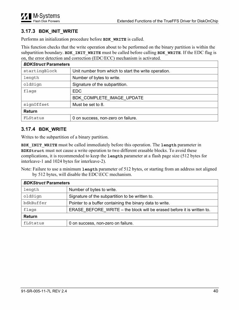
3.17.3 BDK_INIT_WRITE Performs an initialization procedure before BDK_WRITE is called.
This function checks that the write operation about to be performed on the binary partition is within the subpartition boundary. BDK_INIT_WRITE must be called before calling BDK_WRITE. If the EDC flag is on, the error detection and correction (EDC/ECC) mechanism is activated.
BDKStruct Parameters startingBlock Unit number from which to start the write operation. length Number of bytes to write. oldSign Signature of the subpartition.
EDC flags
BDK_COMPLETE_IMAGE_UPDATE signOffset Must be set to 8. Return FLStatus 0 on success, non-zero on failure.
3.17.4 BDK_WRITE Writes to the subpartition of a binary partition.
BDK_INIT_WRITE must be called immediately before this operation. The length parameter in BDKStruct must not cause a write operation to two different erasable blocks. To avoid these complications, it is recommended to keep the length parameter at a flash page size (512 bytes for interleave-1 and 1024 bytes for interleave-2).
Note: Failure to use a minimum length parameter of 512 bytes, or starting from an address not aligned by 512 bytes, will disable the EDC\ECC mechanism.
BDKStruct Parameters length Number of bytes to write. oldSign Signature of the subpartition to be written to. bdkBuffer Pointer to a buffer containing the binary data to write. flags ERASE_BEFORE_WRITE – the block will be erased before it is written to. Return fLStatus 0 on success, non-zero on failure.
Extended Functions of the TrueFFS Driver for DiskOnChip
91-SR-005-11-7L REV 2.4 41
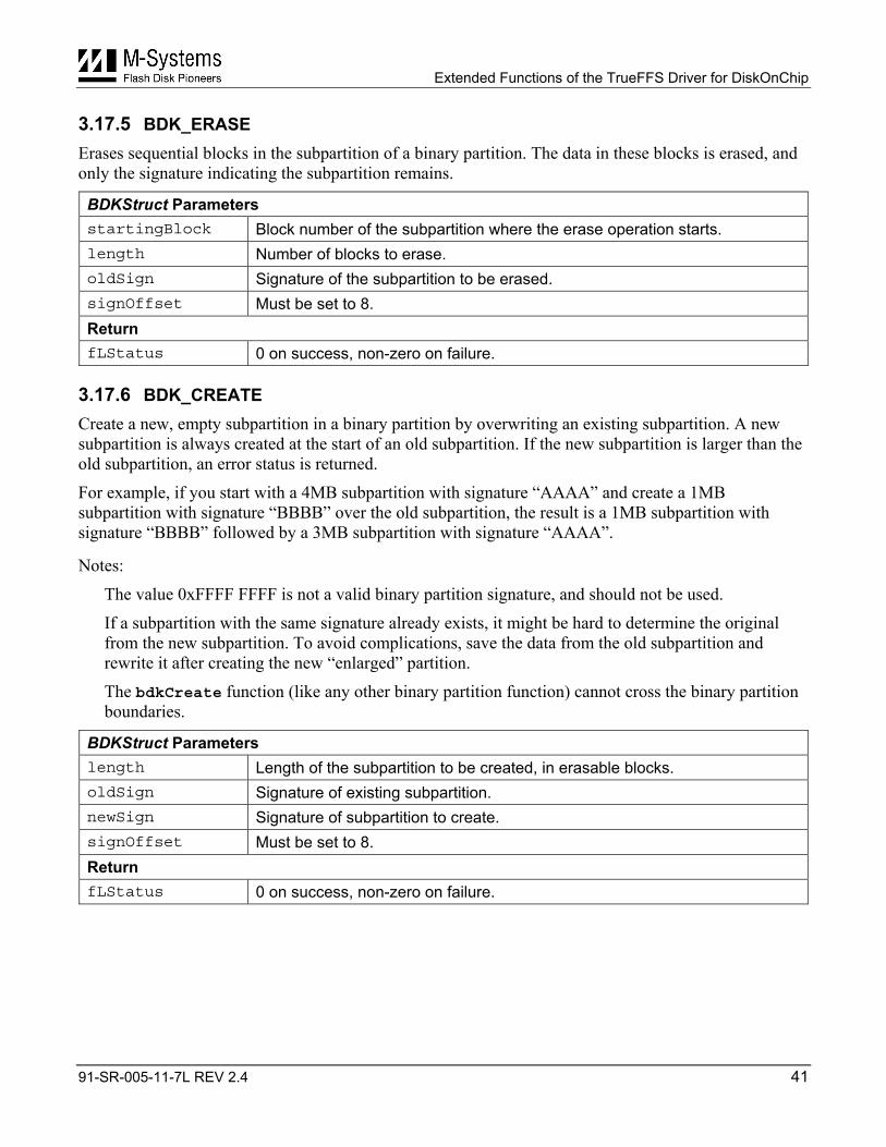
3.17.5 BDK_ERASE Erases sequential blocks in the subpartition of a binary partition. The data in these blocks is erased, and only the signature indicating the subpartition remains.
BDKStruct Parameters startingBlock Block number of the subpartition where the erase operation starts. length Number of blocks to erase. oldSign Signature of the subpartition to be erased. signOffset Must be set to 8. Return fLStatus 0 on success, non-zero on failure.
3.17.6 BDK_CREATE Create a new, empty subpartition in a binary partition by overwriting an existing subpartition. A new subpartition is always created at the start of an old subpartition. If the new subpartition is larger than the old subpartition, an error status is returned.
For example, if you start with a 4MB subpartition with signature “AAAA” and create a 1MB subpartition with signature “BBBB” over the old subpartition, the result is a 1MB subpartition with signature “BBBB” followed by a 3MB subpartition with signature “AAAA”.
Notes:
The value 0xFFFF FFFF is not a valid binary partition signature, and should not be used.
If a subpartition with the same signature already exists, it might be hard to determine the original from the new subpartition. To avoid complications, save the data from the old subpartition and rewrite it after creating the new “enlarged” partition.
The bdkCreate function (like any other binary partition function) cannot cross the binary partition boundaries.
BDKStruct Parameters length Length of the subpartition to be created, in erasable blocks. oldSign Signature of existing subpartition. newSign Signature of subpartition to create. signOffset Must be set to 8. Return fLStatus 0 on success, non-zero on failure.
Extended Functions of the TrueFFS Driver for DiskOnChip
91-SR-005-11-7L REV 2.4 42
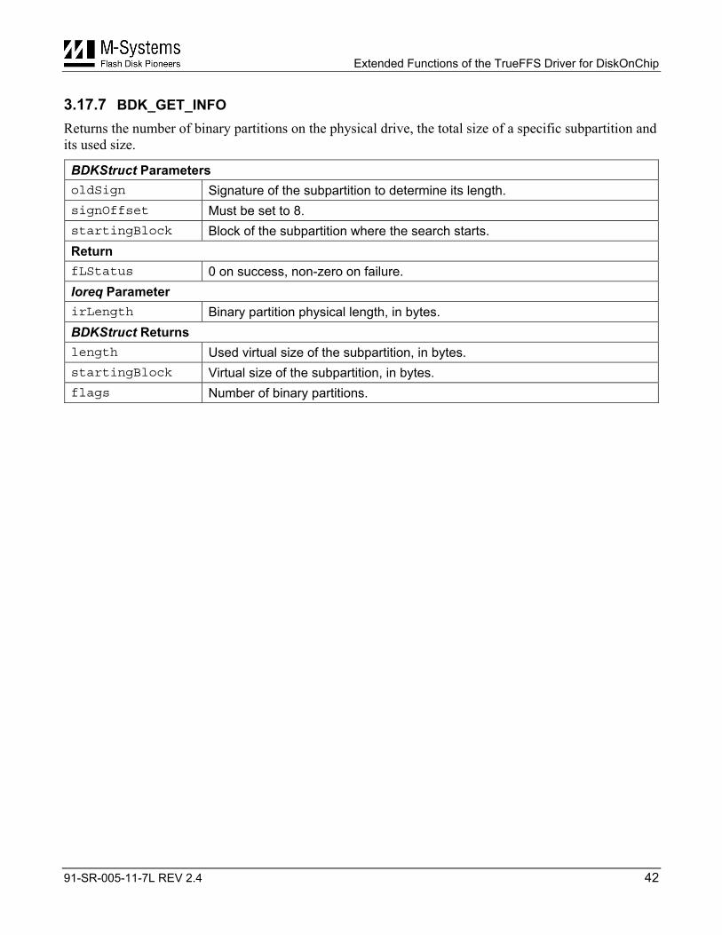
3.17.7 BDK_GET_INFO Returns the number of binary partitions on the physical drive, the total size of a specific subpartition and its used size.
BDKStruct Parameters oldSign Signature of the subpartition to determine its length. signOffset Must be set to 8. startingBlock Block of the subpartition where the search starts. Return fLStatus 0 on success, non-zero on failure. Ioreq Parameter irLength Binary partition physical length, in bytes. BDKStruct Returns length Used virtual size of the subpartition, in bytes. startingBlock Virtual size of the subpartition, in bytes. flags Number of binary partitions.
Extended Functions of the TrueFFS Driver for DiskOnChip
91-SR-005-11-7L REV 2.4 43
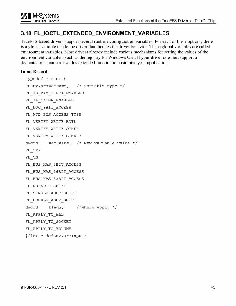
3.18 FL_IOCTL_EXTENDED_ENVIRONMENT_VARIABLES TrueFFS-based drivers support several runtime configuration variables. For each of these options, there is a global variable inside the driver that dictates the driver behavior. These global variables are called environment variables. Most drivers already include various mechanisms for setting the values of the environment variables (such as the registry for Windows CE). If your driver does not support a dedicated mechanism, use this extended function to customize your application.
Input Record typedef struct {
FLEnvVars varName; /* Variable type */
FL_IS_RAM_CHECK_ENABLED
FL_TL_CACHE_ENABLED
FL_DOC_8BIT_ACCESS
FL_MTD_BUS_ACCESS_TYPE
FL_VERIFY_WRITE_BDTL
FL_VERIFY_WRITE_OTHER
FL_VERIFY_WRITE_BINARY
dword varValue; /* New variable value */
FL_OFF
FL_ON
FL_BUS_HAS_8BIT_ACCESS
FL_BUS_HAS_16BIT_ACCESS
FL_BUS_HAS_32BIT_ACCESS
FL_NO_ADDR_SHIFT
FL_SINGLE_ADDR_SHIFT
FL_DOUBLE_ADDR_SHIFT
dword flags; /*Where apply */
FL_APPLY_TO_ALL
FL_APPLY_TO_SOCKET
FL_APPLY_TO_VOLUME
}flExtendedEnvVarsInput;
Extended Functions of the TrueFFS Driver for DiskOnChip
91-SR-005-11-7L REV 2.4 44
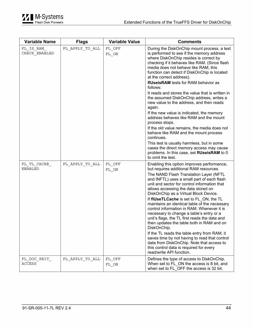
Variable Name Flags Variable Value Comments
FL_IS_RAM_ CHECK_ENABLED
FL_APPLY_TO_ALL FL_OFF
FL_ON During the DiskOnChip mount process, a test is performed to see if the memory address where DiskOnChip resides is correct by checking if it behaves like RAM. (Since flash media does not behave like RAM, this function can detect if DiskOnChip is located at the correct address). flUseisRAM tests for RAM behavior as follows: It reads and stores the value that is written in the assumed DiskOnChip address, writes a new value to the address, and then reads again. If the new value is indicated, the memory address behaves like RAM and the mount process stops. If the old value remains, the media does not behave like RAM and the mount process continues. This test is usually harmless, but in some cases the direct memory access may cause problems. In this case, set flUseisRAM to 0 to omit the test.
FL_TL_CACHE_ ENABLED
FL_APPLY_TO_ALL FL_OFF
FL_ON Enabling this option improves performance, but requires additional RAM resources. The NAND Flash Translation Layer (NFTL and INFTL) uses a small part of each flash unit and sector for control information that allows accessing the data stored on DiskOnChip as a Virtual Block Device. If flUseTLCache is set to FL_ON, the TL maintains an identical table of the necessary control information in RAM. Whenever it is necessary to change a table’s entry or a unit’s flags, the TL first reads the data and then updates the table both in RAM and on DiskOnChip. If the TL reads the table entry from RAM, it saves time by not having to read that control data from DiskOnChip. Note that access to this control data is required for every read/write API function.
FL_DOC_8BIT_ ACCESS
FL_APPLY_TO_ALL FL_OFF
FL_ON Defines the type of access to DiskOnChip. When set to FL_ON the access is 8 bit, and when set to FL_OFF the access is 32 bit.
Extended Functions of the TrueFFS Driver for DiskOnChip
91-SR-005-11-7L REV 2.4 45
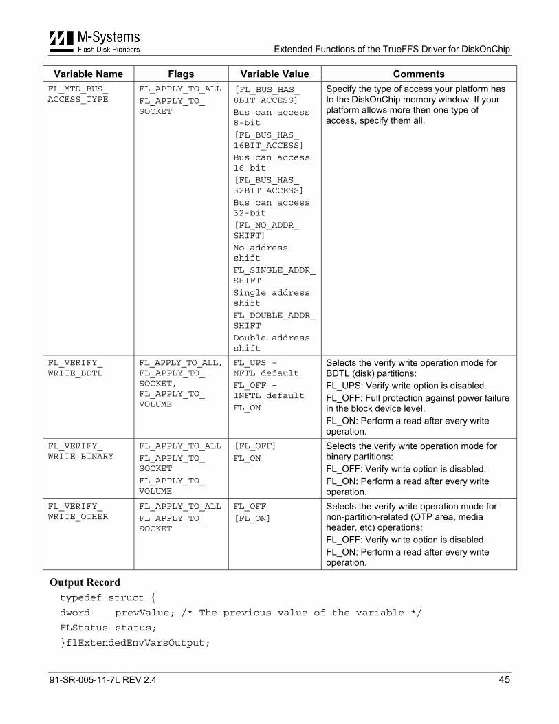
Variable Name Flags Variable Value Comments FL_MTD_BUS_ ACCESS_TYPE
FL_APPLY_TO_ALL
FL_APPLY_TO_ SOCKET
[FL_BUS_HAS_ 8BIT_ACCESS]
Bus can access 8-bit
[FL_BUS_HAS_ 16BIT_ACCESS]
Bus can access 16-bit
[FL_BUS_HAS_ 32BIT_ACCESS]
Bus can access 32-bit
[FL_NO_ADDR_ SHIFT]
No address shift
FL_SINGLE_ADDR_SHIFT
Single address shift
FL_DOUBLE_ADDR_SHIFT
Double address shift
Specify the type of access your platform has to the DiskOnChip memory window. If your platform allows more then one type of access, specify them all.
FL_VERIFY_ WRITE_BDTL
FL_APPLY_TO_ALL, FL_APPLY_TO_ SOCKET, FL_APPLY_TO_ VOLUME
FL_UPS – NFTL default
FL_OFF – INFTL default
FL_ON
Selects the verify write operation mode for BDTL (disk) partitions: FL_UPS: Verify write option is disabled. FL_OFF: Full protection against power failure in the block device level. FL_ON: Perform a read after every write operation.
FL_VERIFY_ WRITE_BINARY
FL_APPLY_TO_ALL
FL_APPLY_TO_ SOCKET
FL_APPLY_TO_ VOLUME
[FL_OFF]
FL_ON Selects the verify write operation mode for binary partitions: FL_OFF: Verify write option is disabled. FL_ON: Perform a read after every write operation.
FL_VERIFY_ WRITE_OTHER
FL_APPLY_TO_ALL
FL_APPLY_TO_ SOCKET
FL_OFF
[FL_ON] Selects the verify write operation mode for non-partition-related (OTP area, media header, etc) operations: FL_OFF: Verify write option is disabled. FL_ON: Perform a read after every write operation.
Output Record typedef struct {
dword prevValue; /* The previous value of the variable */
FLStatus status;
}flExtendedEnvVarsOutput;
Extended Functions of the TrueFFS Driver for DiskOnChip
91-SR-005-11-7L REV 2.4 46
3.19 FL_IOCTL_VERIFY_VOLUME Scans the partition for sectors that are only partially written due to power failure events.
Input Record typedef struct {
dword flags; /* Must be set to 0 */
} flVerifyVolumeInput;
Output Record typedef struct {
void FAR1* callBack; /* Must be set to null */
FLStatus status;
} flVerifyVolumeOutput;
3.20 FL_IOCTL_EXTENDED_WRITE_IPL Writes data to the IPL region of DiskOnChip Millennium Plus and Mobile DiskOnChip.
Notes:
The IPL for DiskOnChip 2000 is stored on a ROM block and cannot be changed.
The 8MB DiskOnChip Millennium 512-byte SRAM block is initialized with the contents of the first 512-byte page of unit 0 on the flash media. The following page should hold a redundant copy of the IPL code, which is read automatically of there is an EDC error on the first page. Both pages can be written using the binary partition extended functionalities, provided that the media is preformatted with a binary partition.
To determine if your device supports the write IPL extended functionality, call the FL_IOCTL_INQUIRE_CAPABILITIES function with the SUPPORT_WRITE_IPL_ROUTINE option (see Section 3.12).
DiskOnChip Millennium Plus 16MB and Mobile DiskOnChip 16MB support the following options, specified in the flags field of the input structure:
FL_IPL_MODE_NORMAL 0 No special mode. FL_IPL_DOWNLOAD 1 Force download of a new IPL. FL_IPL_MODE_XSCALE 4 Enable XScale mode: Full asynchronous address change is
detected automatically by the DiskOnChip controller.
Input Record typedef struct {
byte FAR1* buf; /* IPL data buffer */
word flags; /* IPL flags */
word bufLen; /* IPL data buffer length */
} flIplInput;
Extended Functions of the TrueFFS Driver for DiskOnChip
91-SR-005-11-7L REV 2.4 47
Output Record typedef struct {
FLStatus status;
} flOutputStatusRecord;
Extended Functions of the TrueFFS Driver for DiskOnChip
91-SR-005-11-7L REV 2.4 48
4 Additional Information and Tools Additional information about DiskOnChip, including application notes, data sheets, and utilities can be found at http://www.m-sys.com.
Additional tools and documents are listed in the following table:
Document/Tool Description Application Note, AP-DOC-017 Designing with DiskOnChip in Windows CE Developer Guide DiskOnChip Boot Software Development Kit (BDK) Installation Manual Manuals for specific OSs are enclosed with the driver
package in PDF format User Manual DiskOnChip Software Utilities
Extended Functions of the TrueFFS Driver for DiskOnChip
How to Contact Us Internet: http://www.m-sys.com
General Information: [email protected]
Sales and Technical Information: [email protected] USA M-Systems Inc. 8371 Central Ave, Suite A Newark CA 94560 Phone: +1-510-494-2090 Fax: +1-510-494-5545
Taiwan M-Systems Asia Ltd. Room B, 13 F, No. 133 Sec. 3 Min Sheng East Road Taipei, Taiwan R.O.C. Tel: +886-2-8770-6226 Fax: +886-2-8770-6295
Japan M-Systems Japan Inc. Asahi Seimei Gotanda Bldg., 3F 5-25-16 Higashi-Gotanda Shinagawa-ku Tokyo, 141-0022 Phone: +81-3-5423-8101 Fax: +81-3-5423-8102
China M-Systems China Ltd. 25A International Business Commercial Bldg. Nanhu Rd., Lou Hu District Shenzhen, China 518001 Phone: +86-755-519-4732 Fax: +86-755-519-4729
Europe and Israel M-Systems Ltd. 7 Atir Yeda St. Kfar Saba 44425, Israel Tel: +972-9-764-5000 Fax: +972-3-548-8666
© 2002 M-Systems Flash Disk Pioneers, Ltd. All rights reserved.
This document is for information use only and is subject to change without prior notice. M-Systems Flash Disk Pioneers Ltd. assumes no responsibility for any errors that may appear in this document. No part of this document may be reproduced, transmitted, transcribed, stored in a retrievable manner or translated into any language or computer language, in any form or by any means, electronic, mechanical, magnetic, optical, chemical, manual or otherwise, without prior written consent of M-Systems.
M-Systems products are not warranted to operate without failure. Accordingly, in any use of the Product in life support systems or other applications where failure could cause injury or loss of life, the Product should only be incorporated in systems designed with appropriate and sufficient redundancy or backup features.
Contact your local M-Systems sales office or distributor, or visit our website at www.m-sys.com to obtain the latest specifications before placing your order.
DiskOnChip®, DiskOnChip Millennium® DiskOnKey® and TrueFFS® are registered trademarks of M-Systems. FFD™ and SuperMAP™ are trademarks of M-Systems. Other product names mentioned in this document may be trademarks or registered trademarks of their respective owners and are hereby acknowledged.
91-SR-005-11-7L REV 2.4 49