Embed Size (px)
Citation preview
TB 43-0213
DEPARTMENT OF THE ARMY TECHNICAL BULLETIN
CORROSION PREVENTIONAND CONTROL
INCLUDING RUSTPROOFING PROCEDURESFOR
TACTICAL VEHICLES AND TRAILERS
This technical bulletin supersedes TB 43-0213, 22 August 1983.
Approved for public release: distribution is unlimited.
HEADQUARTERS, DEPARTMENT OF THE ARMY
4 December 1990

TB 43-0213
WARNING SUMMARY
The following is a list of some of the WARNINGS that appear in this Technical Bulletin, as well as general safetyprecautions that are not related to any specific procedure and do not appear elsewhere in this publication.Rustproofing technicians must become familiar with all warnings and general safety precautions. Severe injury,health hazards, and death can be avoided by technicians who know and understand these warnings.
●
●
●
●
●
●
High pressure spray can cause serious injury or death. Never put hands, or any other part of the body, infront of the rustproofing spray tool. Severe infection, blood poisoning, and gangrene requiring amputationof a limb can result from skin penetration of the rustproofing material under high pressure. Summon aphysician immediately! Inform the physician that the material injected into the skin is a petroleumcompound containing aliphatic petroleum naptha with an effect similar to kerosene.
.Injection injuries can occur as a result of pinhole leaks, splits, or rupture in the hosing due to wear, damage,or misuse. Never use a damaged hose. Never attempt to contain sudden hose leaks with hands. Instead,stand clear of ruptures and shut down the pump. Always check hosing and couplings before use. Ifcouplings disconnect during operation, never attempt to recouple with the pump still running. Never menddamaged hose with tape or any other device. Repaired hoses cannot effectively contain high pressure fluidsand are extremely dangerous.
Whenever the rustproofing procedure requires the use of a hoist, ensure that the hoist has the capacity tolift and secure the vehicle. Hoist used must be equipped with a safety bar or safety locking device.Operation of the safety bar or locking device should be checked daily.
Open air compressors should have drive belts enclosed with a wire mesh screen. Air compressors used mustbe equipped with a safety valve in good working order,
Silica exposure hazards exist whenever sand particles are injected into the air. Wet sandblasting lessenshealth risks, but care must be taken to ensure that applicators use the recommended protective equipment.Silica exposure due to failure to wear protective equipment can result in silicosis, a lung disease similar toemphysema.
Drilling metals can be extremely dangerous. Wear proper eye protection and keep hands away from cuttingtool, Sharp fragments may remain around the drilling area. Use extreme caution when touching theseareas.
DO NOT smoke in the work area. Airborne rustproofing material is flammable. Fire extinguishers must bereadily available. Personnel must be familiar with the use of fire extinguishers. Fire extinguishers should beinspected on a regular basis and recharged as soon as possible after use.
“No Smoking” signs must be prominently displayed in the rustproofing area. Phone numbers for the nearestfire department and ambulance service should be displayed near each phone.
Rustproofing compound should never be stored in an area where the temperature is above 100 degrees F(38 degrees C). Dispose of empty drums immediately. Solvents must be stored in approved containers(metal cans with automatic safety lids). Excessive amounts of solvents should never be ordered and storedin the facility,
Personnel must be aware of rustproofing materials and various solvent hazards before using such materials.
Work areas must be kept clean to prevent accidents. All used rags should be stored in approved safety cans.Debris should not be allowed to accumulate on the work area floor as it will present tripping and firehazards,
Goggles or safety glasses and a protective mask should be worn during all phases of the rustproofingprocedure, When processing the underside of the vehicle, use of goggles and a safety mask is essential tosafety of personnel. Shoes with non-skid soles, an apron glove, and a long-sleeved shirt should also be worn.
a

TB 43-0213
•
•
•
•
•
b
Rustproofing work areas must be adequately ventilated. All personnel in immediate adjacent areas whererustproofing material is being sprayed should also wear an approved respirator mask.
High pressure washers can discharge water and debris through vent holes in excess of 1200 psi (8274 kPa).High pressure washer operators must direct all personnel to stand clear of the vehicle during cleaningoperations. Operators must wear eye protection to prevent serious injury from wash-back during cleaningoperations.
Electrical receptacles in work areas must be properly seated and grounded. Electrical cords used must be ingood condition and provide grounding for the tool.
Static electricity is created by a high velocity flow of fluid through the pump and hose. For this reason, thedispensing system must be properly grounded. If not, sparking may occur which can ignite fumes fromsolvents, dust, or other flammable substances. Spark ignition of flammable materials can result in anexplosion and serious bodily injury. To prevent such hazards, ensure that the equipment is properlygrounded.
For first aid information, refer to FM 21-11.

TECHNICAL BULLETIN
NO. 43-0213
DEPARTMENT
*TB 43-0213
HEADQUARTERSDEPARTMENT OF THE ARMY
WASHINGTON, D. C., 4 December 1990
OF THE ARMY TECHNICAL BULLETIN
CORROSION PREVENTION AND CONTROLINCLUDING RUSTPROOFING PROCEDURESFOR TACTICAL VEHICLES AND TRAILERS
REPORTING ERRORS AND RECOMMENDING IMPROVEMENTS
You can help improve this manual. If you find any mistakes or if you know of a way to improve theprocedures, please let us know. Mail your letter, DA Form 2028 (Recommended Changes to Publicationsand Blank Forms), or DA Form 2028-2, Iocated in the back of this manual, direct to: Commander, U.S.Army Tank-Automotive Command, ATTN: AMSTA-MB, Warren, Ml 48397-5000, A reply will be fur-nished to you.
TABLE OF CONTENTS
Page
Chapter 1
Section I.
Section II.
Chapter 2
Section I.
Section II.
INTRODUCTION . . . . . . . . . . . . . . . . . . . . . . . . . . . . . . . . . . . . . . . . . . . . . . .
General . . . . . . . . . . . . . . . . . . . . . . . . . . . . . . . . . . . . . . . . . . . . . . . . . . . . . .
Description and Data... . . . . . . . . . . . . . . . . . . . . . . . . . . . . . . . . .
CORROSION PREVENTION AND CONTROL , . . . . . . . . . . . . . . . . . . . . .
Rusting -The Electrochemical Reaction . . . . . . . . . . . . . . . . . . . . . . . . . . ,
Other Types of Corrosion . . . . . . . . . . . . . . . . . . . . . . . . . . . . . . . . . . . . . . .
Section III. Corrosion Removing Compounds. . . . . . . . . . . . . . . . . . . . . . . . . . . . . . . . .
Chapter 3 RUSTPROOFING EQUIPMENT/EQUIPMENT MAINTENANCEAND PRELIMINARY INSTRUCTIONS . . . . . . . . . . . . . . . . . . . . . . . . . . . .
Section I. Rustproofing Equipment and Materials . . . . . . . . . . . . . . . . . . . . . . . . . . . .
Section II. Rustproofing Application Techniques . . . . . . . . . . . . . . . . . . . . . . . . . . . . . .
Section III. Vehicle Preparation.... . . . . . . . . . . . . . . . . . . . . . . . . . . . . . . . . . .
Chapter 4 1/4-TON TRUCK: M151, M718, AND M825 SERIES . . . . . . . . . . . . . . .
Section I.
Section II.
Section III.
* This technical
Preliminary Procedures . . . . . . . . . . . . . . . . . . . . . . . . . . . . . . . . . . .
Drilling and Cleaning Procedures . . . . . . . . . . . . . . . . . . . . . . . . . . . . . . . . .
Rustproofing Procedures.... . . . . . . . . . . . . . . . . . . . . . . . . . . . . . . . . . .
bulletin supersedes TB 43-0213, 22 August 1983.
1-1
1-1
1-4
2-1
2-1
2-8
2-12
3-1
3-1
3-19
3-21
4-1
4-1
4-1
4-8
i

TB 43-0213
TABLE OF CONTENTS (Con’t)
Chapter 5 1
Section I.
Section II.
Section III.
1/4-TON TRUCK: M880 AND M890 SERIES . . . . . . . . . . . . . . . . . . . . .
Preliminary Procedures . . . . . . . . . . . . . . . . . . . . . . . . . . . . . . . . . . . . . . . . .
Drilling and Cleaning Procedures . . . . . . . . . . .
Rustproofing Procedures . . . . . . . . . . . . . . . . . .
Chapter 6 3/4-TON AND 1 1/4-TON/TRUCK: M1008, MM1009, M1010, M1028, AND M1031 . . . . . . . .
. . . . . . . . . . . . . . . . . . . . .
. . . . . . . . .
008A1,. . . . . . . . . . . . . . . . . . . . .
Section I.
Section II.
Section III.
Chapter 7 2
Section I.
Section II.
Section III.
Chapter 8 2
Section I.
Section II.
Section III.
Chapter 9 2
Section I.
Section II.
Section III.
Chapter 10 2
Section I.
Section II.
Chapter 11 2
Section I.
Section II.
Chapter 12 2
Section I.
Section H.
Preliminary Procedures . . . . . . . . . . . . . . . . . . . . . . . . . . . . . . . . . . . . . . . . .
Drilling and Cleaning Procedures . . . . . . . . . . . . . . . . . . . . . . . . . . . . . . . . .
Rustproofing Procedures . . . . . . . . . . . . . . . . . . . . . . . . . . . . . . . . . . . . . . . .
1/2-TONAND 5-TON TRUCKS: CABS (TYPICAL) . . . . . . . . . . . . . . .
Preliminary Procedures . . . . . . . . . . . . . . . . . . . . . . . . . . . . . . . . . . . . . . . . .
Drilling and Cleaning Procedures . . . . . . . . . . . . . . . . . . . . . . . . . . . . . . . . .
Rustproofing Procedures . . . . . . . . . . . . . . . . . . . . . . . . . . . . . . . . . . . . . . . .
1/2-ToN CARGO BODY TRUCKS . . . . . . . . . . . . . . . . . . . . . . . . . . . .
Preliminary Procedures . . . . . . . . . . . . . . . . . . . . . . . . . . . . . . . . . . . . . . . . .
Drilling and Cleaning Procedures . . . . . . . . . . . . . . . . . . . . . . . . . . . . . . . . .
Rustproofing Procedures . . . . . . . . . . . . . . . . . . . . . . . . . . . . . . . . . . . . . . . .
1/2-TON TRUCKS: DUMP BODY AND TAILGATE . . . . . . . . . . . . . . .
Preliminary Procedures . . . . . . . . . . . . . . . . . . . . . . . . . . . . . . . . . . . . . . . . .
Drilling and Cleaning Procedures . . . . . . . . . . . . . . . . . . . . . . . . . . . . . . . . .
Rustproofing Procedures . . . . . . . . . . . . . . . . . . . . . . . . . . . . . . . . . . . . . . . .
1/2-TON TRUCKS: WATER TANKERS . . . . . . . . . . . . . . . . . . . . . . . . . .
Drilling and Cleaning Procedures . . . . . . . . . . . . . . . . . . . . . . . . . . . . . . . . .
Rustproofing Procedures . . . . . . . . . . . . . . . . . . . . . . . . . . . . . . . . . . . . . . . .
1/2-TON TRUCKS: FUEL TANKERS . . . . . . . . . . . . . . . . . . . . . . . . . . . .
Drilling and Cleaning Procedures . . . . . . . . . . . . . . . . . . . . . . . . . . . . . . . . .
Rustproofing Procedures . . . . . . . . . . . . . . . . . . . . . . . . . . . . . . . . . .
1/2-TONT RUCKS: VAN BODY . . . . . . . . . . . . . . . . . . . . . . . . . . . . . . . .
Cleaning Procedures . . . . . . . . . . . . . . . . . . . . . . . . . . . . . . . . . ..
Rustproofing Procedures . . . . . . . . . . . . . . . . . . . . . . . . . . . . . .
Chapter 13 5-TON TRUCKS: CARGO BODY . . . . . . . . . . . . . . . . . . . . . . . . . . . . . . . . .
Section I. Preliminary Procedures . . . . . . . . . . . . . . . . . . . . . . . . . . . . . . . . . . . . . . . . .
Section II. DrilIing and Cleaning Procedures . . . . . . . . . . . . . . . . . . . . . . . . . . . . . . . . .
Section HI. Rustproofing Procedures . . . . . . . . . . . . . . . . . . . . . . . . . . . . . . . . ...
Page
5-1
5-1
5-2
5-6
6-1
6-1
6-2
6-5
7-1
7-1
7-2
7-4
8-1
8-1
8-1
8-2 ‘
9-1
9-1
9-1
9-4
10-1
10-1
10-3
11-1
11-1
11-3
12-1
12-1
12-2
13-1
13-1
13-1
13-3
ii
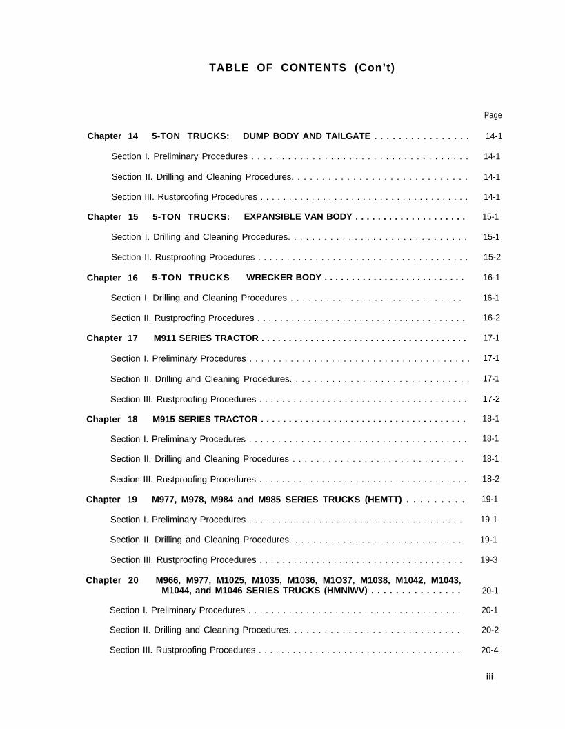
TABLE OF CONTENTS (Con’t)
Chapter 14 5-TON TRUCKS: DUMP BODY AND TAILGATE . . . . . . . . . . . . . . . .
Section I. Preliminary Procedures . . . . . . . . . . . . . . . . . . . . . . . . . . . . . . . . . . . .
Section II. Drilling and Cleaning Procedures. . . . . . . . . . . . . . . . . . . . . . . . . . . . .
Section III. Rustproofing Procedures . . . . . . . . . . . . . . . . . . . . . . . . . . . . . . . . . . . . .
Chapter 15 5-TON TRUCKS: EXPANSIBLE VAN BODY . . . . . . . . . . . . . . . . . . . .
Section I. Drilling and Cleaning Procedures. . . . . . . . . . . . . . . . . . . . . . . . . . . . . .
Section II. Rustproofing Procedures . . . . . . . . . . . . . . . . . . . . . . . . . . . . . . . . . . . . .
Chapter 16 5-TON TRUCKS WRECKER BODY . . . . . . . . . . . . . . . . . . . . . . . . . .
Section I. Drilling and Cleaning Procedures . . . . . . . . . . . . . . . . . . . . . . . . . . . . .
Section II. Rustproofing Procedures . . . . . . . . . . . . . . . . . . . . . . . . . . . . . . . . . . . . .
Chapter 17 M911 SERIES TRACTOR . . . . . . . . . . . . . . . . . . . . . . . . . . . . . . . . . . . . . .
Section I. Preliminary Procedures . . . . . . . . . . . . . . . . . . . . . . . . . . . . . . . . . . . . . .
Section II. Drilling and Cleaning Procedures. . . . . . . . . . . . . . . . . . . . . . . . . . . . . .
Section III. Rustproofing Procedures . . . . . . . . . . . . . . . . . . . . . . . . . . . . . . . . . . . . .
Chapter 18 M915 SERIES TRACTOR . . . . . . . . . . . . . . . . . . . . . . . . . . . . . . . . . . . . .
Section I. Preliminary Procedures . . . . . . . . . . . . . . . . . . . . . . . . . . . . . . . . . . . . . .
Section II. Drilling and Cleaning Procedures . . . . . . . . . . . . . . . . . . . . . . . . . . . . .
Section III. Rustproofing Procedures . . . . . . . . . . . . . . . . . . . . . . . . . . . . . . . . . . . . .
Chapter 19 M977, M978, M984 and M985 SERIES TRUCKS (HEMTT) . . . . . . . . .
Section I. Preliminary Procedures . . . . . . . . . . . . . . . . . . . . . . . . . . . . . . . . . . . . .
Section II. Drilling and Cleaning Procedures. . . . . . . . . . . . . . . . . . . . . . . . . . . . .
Section III. Rustproofing Procedures . . . . . . . . . . . . . . . . . . . . . . . . . . . . . . . . . . . .
Chapter 20 M966, M977, M1025, M1035, M1036, M1O37, M1038, M1042, M1043,M1044, and M1046 SERIES TRUCKS (HMNlWV) . . . . . . . . . . . . . . .
Section I. Preliminary Procedures . . . . . . . . . . . . . . . . . . . . . . . . . . . . . . . . . . . . .
Section II. Drilling and Cleaning Procedures. . . . . . . . . . . . . . . . . . . . . . . . . . . . .
Section III. Rustproofing Procedures . . . . . . . . . . . . . . . . . . . . . . . . . . . . . . . . . . . .
Page
14-1
14-1
14-1
14-1
15-1
15-1
15-2
16-1
16-1
16-2
17-1
17-1
17-1
17-2
18-1
18-1
18-1
18-2
19-1
19-1
19-1
19-3
20-1
20-1
20-2
20-4
iii

TABLE OF CONTENTS (Con’t)
Chapter 21 1/4-TON TRAILER M416 SERIES . . . . . . . . . . . . . . . . . . . . . . . . . . . . 21-1
Section I. Cleaning Procedures . . . . . . . . . . . . . . . . . . . . . . . . . . . . . . . . . . . . . . . . 21-1
Section II. Rustproofing Procedures . . . . . . . . . . . . . . . . . . . . . . . . . . . . . . . . . . . . 21-1
Chapter22 3/4-ToN TRAILER. M101 SERIES . . . . . . . . . . . . . . . . . . . . . . . . . . . 22-1
Section I. Drilling and Cleaning Procedures. . . . . . . . . . . . . . . . . . . . . . . . . . . . . 22-1
Section II. Rustproofing Procedures . . . . . . . . . . . . . . . . . . . . . . . . . . . . . . . . . . . . 22-3
Chapter 23 1 1/2-TON CARGO TRAILER M105 SERIES . . . . . . . . . . . . . . . . . . . . . 23-1
Section I. Drilling and Cleaning Procedures . . . . . . . . . . . . . . . . . . . . . . . . . . . . . 23-1
Section II. Rustproofing Procedures . . . . . . . . . . . . . . . . . . . . . . . . . . . . . . . . . . . . . 23-2
APPENDIX A REFERENCES . . . . . . . . . . . . . . . . . . . . . . . . . . . . . . . . . . . . . . . . . . . . A-1
APPENDIX B CORROSION AREAS. . . . . . . . . . . . . . . . . . . . . . . . . . . . . . . . . . . . . . B-1
APPENDIXC RUST REPAIR PARTS/REPAIR KITS . . . . . . . . . . . . . . . . . . . . . . . C-1
APPENDIX D RUST REPAIR AND BODY REPLACEMENT INSTRUCTIONSFOR M151, M718, AND M825 SERlES Trucks . . . . . . . . . . . . . . . . . D-1
APPENDIX E FABRICATED TOOLS . . . . . . . . . . . . . . . . . . . . . . . . . . . . . . . . E-1
Section I. Straight-Edge Floor Scraper.. . . . . . . . . . . . . . . . . . . . . . . . . . . . . . . . . E-1
Section II. Looped Scraper.. . . . . . . . . . . . . . . . . . . . . . . . . . . . . . . . . . . . . . . . . . . E-2
APPENDIX F GLOSSARY OF TERMS . . . . . . . . . . . . . . . . . . . . . . . . . . . . . . . . . . . . F-1
Table
1-1.
1-2.
INDEX . . . . . . . . . . . . . . . . . . . . . . . . . . . . . . . . . . . . . Index 1
LIST OF TABLES
Title Page
Tactical Vehicle Rustproofing Instructions. . . . . . . . . . . . . . . . . . . . . . . . 1-2
Trailer Rustproofing Instructions . . . . . . . . . . . . . . . . . . . . . . . . . . . . . . . 1-3
iv

Table
1-3.
1-4.
1-5.
2-1.
2-2.
2-3.
3-1.
3-2.
3-3.
3-4.
B-1 .
C-1 .
D-1 .
D-2.
D-3.
D-4.
LIST OF TABLES (Con’ t )
Title
Corrosion Prevention Materials and Their Hazards. . . . . . . . . . . . . . . . .
Toxic Hazard Ratings of Rustproofing Material. . . . . . . . . . . . . . . . . . . .
Airborne Concentration Threshold Limits for Rustproofing Materialper Work Week . . . . . . . . . . . . . . . . . . . . . . . . . . . . . . . . . . . . . . . . . . . .
The Galvanic Corrosion Potential of Differing Metals. . . . . . . . . . . . . . .
The Corrosive Effects of Fuel Oil, Coolants, and Other Fluids . . . . . . . . .
Corrosive Damage Potential During Tests, Services, or Storage . . . . . . .
Rustproofing Compounds . . . . . . . . . . . . . . . . . . . . . . . . . . . . . . . . . . . . .
Rustproofing Equipment . . . . . . . . . . . . . . . . . . . . . . . . . . . . . . . . . . . . .
Troubleshooting Powerwash Equipment . . . . . . . . . . . . . . . . . . . . . . . . .
Trolubleshooting Material Pumps. . . . . . . . . . . . . . . . . . . . . . . . . . . . . .
Recommended Wash Intervals by Severity of Corrosion Areas . . . . . . .
Rust Repair Parts/Repair Kit...... . . . . . . . . . . . . . . . . . . . . . . . . . . .
Underbody Corrosion Repair Kit... . . . . . . . . . . . . . . . . . . . . . . . . . . .
Body Replacement Kit . . . . . . . . . . . . . . . . . . . . . . . . . . . . . . . . . . . . . . .
Specific Torque Values . . . . . . . . . . . . . . . . . . . . . . . . . . . . . . . . . . . . .
Standard Torque Values . . . . . . . . . . . . . . . . . . . . . . . . . . . . . . . . . . . . .
Page
1-5
1-6
1-7
2-10
2-11
2-12
3-1
3-2
3-13
3-14
B-1
C-1
D-1
D-15
D-17
D-20
V
TB 43-0213
CHAPTER 1INTRODUCTION
Section I. GENERAL
1-1. Purpose.
a. This technical bulletin (TB) provides an overviewof the U.S. Army’s Corrosion Prevention and Control(CPC) program, as well as specific instructions forrustproofing select tactical wheeled vehicles andtrailers.
b. This technical bulletin defines types of corrosionas well as key corrosion prevention techniques andmaterials, material application instructions, and impor-tant application safety hazards. This bulletin describesrustproofing equipment available to using units.Equipment operation, maintenance, and troubleshoot-ing procedures are also covered.
c. This technical bulletin is designed to provide abetter understanding of rust, its causes, treatment, andprevention. It includes a detailed introduction torustproofing materials, equipment, and applicationtechniques. Finally, it contains vehicle specificinstructions for rustproofing all tactical vehicles andtrailers listed in Tables 1-1 and 1-2.
d. One additional objective of this technical bulletinis to provide rustproofers with the expertise necessary toadapt rustproofing techniques to other vehicles andtrailers not specifically addressed in this TB.
1-2. Scope.
a. These instructions are applicable to all com-mands, units (including Army National Guard andArmy Reserve), installations, and activities. Implemen-tation of this bulletin by commanders is mandatorywherever corrosion prone or corrosion hazardenvironments dictate essentiality of corrosion preven-tion measures,
b. Saltwater coastal areas, high humidity regions,and all locations requiring use of halite (road salt) forsnow and ice removal are prime areas for theapplications of CPC measures. Areas prone to
industrial pollution, atmospheric pollution (smog), andacid rain are also prime areas for application.
1-3. Reporting of Equipment improvementRecommendations (EIRs).
EIRs can be submitted by anyone who is aware of anunsatisfactory condition, material, material applicationprocedure, as well as with any unsatisfactory conditionin the design or use of any of the rustproofingequipment described herein. It is not necessary to showa new design or to list a better way to perform aprocedure. Rather, simply tell why a procedure isdifficult. EIRs may be submitted on Standard Form 368(Quality Deficiency Report). Mail directly to: Com-mander, U.S. Army Tank-Automotive Command,ATTN: AMSTA-QRT, Warren, MI 48397-5000. Areply will be furnished directly to you,
1-4. Poiicies/Specifications.
a. Unit participation in the CPC Program ismandatory. At the very least, unit participation islimited to scheduled Preventive Maintenance Checksand Services (PMCS). This is because corrosionawareness and early preventive measures greatly reduceArmy vehicle maintenance cost and extend the servicelife of all equipment.
b. The following regulation applies to the CorrosionPrevention and Control Program: AR 750-59, Corro-sion Prevention and Control.
1-5. Vehicie Applications.
a. Table 1-1 lists all tactical vehicles with specificrustproofing instructions in this TB. This list is in simplealphanumeric order according to model number andprovides the chapter(s) where each model’s rustproof-ing instructions can be found.
b. Table 1-2 lists all trailers presented in this TBalong with chapter references.
1-1

TB 43-0213
Table 1-1. Tactical Vehicle Rustproofing Instructions.
1-2

TB 43-0213
Table 1-1. Tactical Vehicle Rustproofing Instructions (Con’t).
Table 1-2, Trailer Rustproofing Instructions.
1-6. Glossary.
Appendix F contains a Glossary of Terms that applies to the rustproofing process and various companents of the vehicles discussed in this technical bulletin
1-7. Abbreviations.ACGIH –
CARC –CONUS –
CPC –EIRs –
FRG –O E M –
PMCS –
Q D R –R O K –SF’T –
SUSP –X M B R –
American Conference of GovernmentalIndustrial HygienistsChemical Agent Resistant CoatingsContinental United StatesCorrosion Prevention and ControlEquipment Improvement Recommen-dationsFederal Republic of GermanyOriginal Equipment ManufacturedPreventive Maintenance Checks andServicesQuality Deficiency ReportRepublic of KoreasupportSuspensionCrossmember
1-3

TB 43-0213
SECTION
1-8 General.
Il. DESCRIPTION AND DATA
a. This section outlines the U.S. Army’s CorrosionPrevention and Control (CPC) Program as well as thegeneric/specific approaches toward rustproofing beingpresented in this technical bulletin.
b. Special considerations and data regardingmaterial hazards, toxic dosage levels, and toxic dosageratings are also presented.
c. Finally, some common misunderstandings re-garding rustproofing materials and applications areclarified.
1-9. The Problem.
a. Corrosion is formally defined as a process ofdissolving or wearing away, especially of metals. Theworld itself is a highly corrosive environment in whichthe dissolution and wearing away of metals and othermaterials is a constant and on-going process.
b. The fundamental source of corrosion is water inthe form of rain, streams, dew, or humidity. One way oranother, water touches upon every exposed andair-reachable surface on this planet.
c. A second major source of corrosion is sunlight.More specifically, the sun’s ultraviolet rays work tocompromise or destroy organic materials such as rubberand paints.
d. Plant life also contributes to the problem ofcorrosion by producing gasses such as ammonia.Recently, scientists discovered that bogs, marshes, andother wetlands of this earth also give off large quantitiesof dimectyl sulfide and hydrogen sulfide. These gasseshappen to be the main chemical ingredients of acid rainwhich was once believed to be produced solely byindustrial pollutants.
e. Corrosion is a by-product of our own naturalenvironment. It is also a natural process, nature’s wayof returning metals and other materials to their naturalstate.
f. Rusting is the most common form of corrosion inthe world today. It causes an estimated $176 billionworth of damage annually in the United States alone.U.S. Army vehicles, because of their intended uses andfunctions, are particularly susceptible to rusting, Suchvehicles are expected to travel off-the-road andoverland through streams and mire in order toaccomplish their mission. The elements—rain, sun,
snow, heat, frost, and humidity—all contribute to thevulnerability of U.S. Army vehicles, as do mud, dust,and stones from the roads impacting on theirundersides.
g. The potential for U.S. military losses due tocorrosion is 11.4 percent of our national losses. Todaythis figure would exceed $20 billion annually.
1-10. Corrosion Prevention and Control(CPC).
a. Corrosion Prevention and Control (CPC) is anArmy-wide effort to improve vehicle readiness and toextend the service life of both current and futurevehicle inventories. Reductions in Army maintenancerequirements, vehicle downtimes, and the high costs ofrepairs are also important objectives of this program.
b. While rustproofing is a major emphasis of CPC, itis only one part of the overall CPC program whichincludes Army initiatives in the following areas:
(1) Design. Army Tank-Automotive procure-ment now places a greater emphasis on corrosion freedesign in all future vehicle buys. This includeseliminating or designing out rust-prone areas, such aspockets and sills in vehicle design, whenever possible aswell as a design preference for corrosion free/corrosionresistant materials in the construction of newequipment. Army procurement design considerationsalso include the vehicle’s manufacturing process andthe stowage requirements of the vehicle. To influencedesign in these directions, the Army has produced a“Design Guide” for private industry that includescorrosion free design considerations, lessons learned,and material selection considerations. In addition, anaccelerated corrosion test that compresses fifteen yearsof service life into a twelve month test period has beenadded to the Army’s new equipment test andacceptance standards. This fact itself influences futurevehicle designs within private industry.
(2) Training. CPC training efforts have beeninitiated toward a greater awareness of corrosion andcorrosion prevention on the part of Army managers,private industry, and equipment users. This greaterawareness is being accomplished by means of the designguide contract requirements, the Corrosion Preventionand Control Program Regulation (see paragraph 1-4),and through formal classroom training and updates to all vehicle specific Army technical manuals. Corrosiondetection, for example, will soon be a standardsemiannual inspection in the Preventive MaintenanceChecks and Services (PMCS) tables for all tank-auto-motive equipment.
1-4
TB 43-0213
(3) Management. To ensure that CPC isemphasized during the deployment of hardware, theArmy has undertaken a program to formalize CPCstandards and requirements. All future ordinancecontracts will be written to include CPC considerationsand will be reinforced by a forthcoming Armyregulation regarding corrosion resistant standards.Automotive representatives in the fields of ProductionManagement, Engineering Item Quality Assurance,Procurement, Contracts, and Equipment Specialists arebeing called upon to ensure implementation of CPC inthe evaluation, test, and selection of new equipment.
(4) Maintenance. The Army has expanded theArmy Oil Analysis Program (AOAP) to include testingfor the presence of iron oxides in the component oilsamples. Also, a corrosion digest providing “lessonslearned” as well as information resulting from Armyresearch projects is being developed. Finally, units arebeing encouraged to submit Quality Deficiency Reports(QDRs) regarding corrosion prevention and control,
(5) Technology. Army research projects incorrosion prevention and control include new studies inthe chemical transformation of rusted metal into asolid, alternative material. Development of a durable,multipurpose and corrosion resistant grease is alsobeing reviewed by Army scientists and engineers alongwith an evaluation of improved diesel fuel stabilizers.Tests are also underway to evaluate the use ofcomposite materials instead of rust-prone metals insome vehicle design applications. Double galvanizedbody designs are also under evaluation by the Army.The actual list of projects and programs underway is farmore extensive, but the above does indicate some keytechnological directions the Army is taking to combatcorrosion and extend the service life of Armyequipment.
1-11. Special Tools.
a. There are several areas on tactical vehicles andtrailers which cannot be cleaned even with repeatedpower washings. Nevertheless, such areas must be cleanprior to rustproofing. Chisels, putty knives, masonry
drills, punches, and other tools may be readilyavailable.
b. A looped scraper, for use in curved areas orhard-to-reach places, can be fabricated from standardshop stock. A straight-edge floor scraper to help cleanup drippings that have pancaked on the shop floor canalso be fabricated from available stock. Refer toAppendix E for instructions on the fabrication of thesetools .
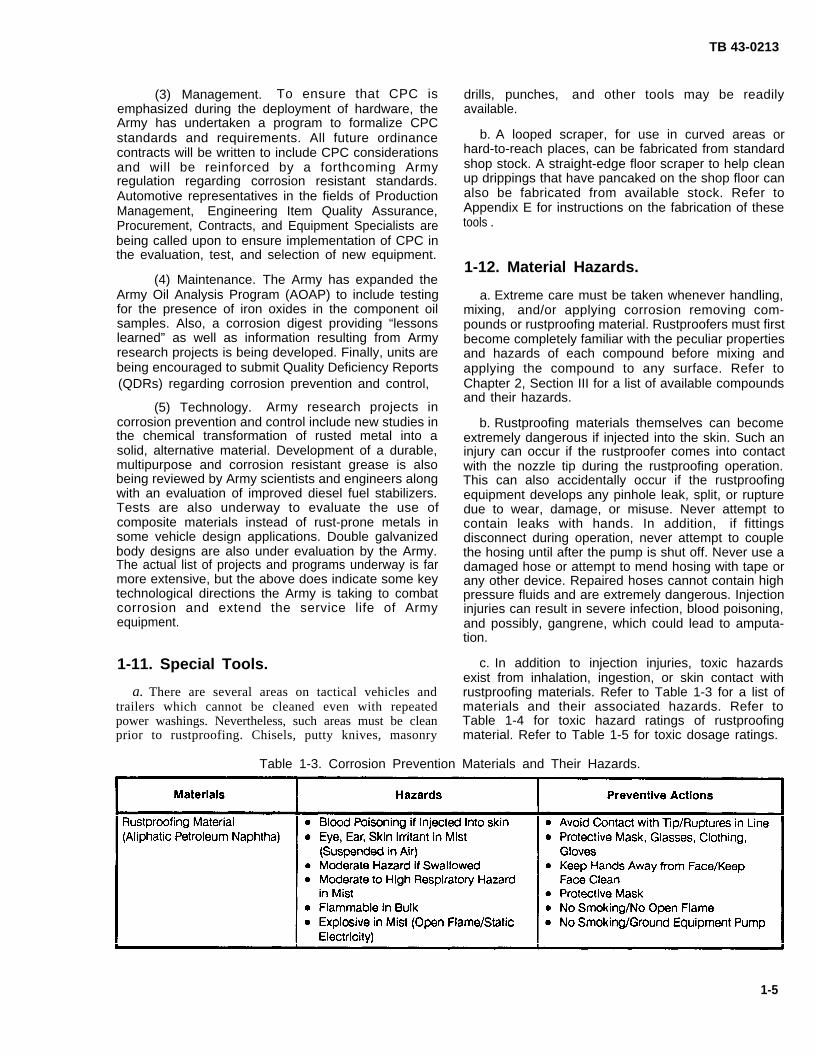
1-12. Material Hazards.
a. Extreme care must be taken whenever handling,mixing, and/or applying corrosion removing com-pounds or rustproofing material. Rustproofers must firstbecome completely familiar with the peculiar propertiesand hazards of each compound before mixing andapplying the compound to any surface. Refer toChapter 2, Section III for a list of available compoundsand their hazards.
b. Rustproofing materials themselves can becomeextremely dangerous if injected into the skin. Such aninjury can occur if the rustproofer comes into contactwith the nozzle tip during the rustproofing operation.This can also accidentally occur if the rustproofingequipment develops any pinhole leak, split, or rupturedue to wear, damage, or misuse. Never attempt tocontain leaks with hands. In addition, if fittingsdisconnect during operation, never attempt to couplethe hosing until after the pump is shut off. Never use adamaged hose or attempt to mend hosing with tape orany other device. Repaired hoses cannot contain highpressure fluids and are extremely dangerous. Injectioninjuries can result in severe infection, blood poisoning,and possibly, gangrene, which could lead to amputa-tion.
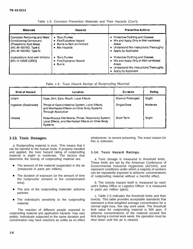
c. In addition to injection injuries, toxic hazardsexist from inhalation, ingestion, or skin contact withrustproofing materials. Refer to Table 1-3 for a list ofmaterials and their associated hazards. Refer toTable 1-4 for toxic hazard ratings of rustproofingmaterial. Refer to Table 1-5 for toxic dosage ratings.
Table 1-3. Corrosion Prevention Materials and Their Hazards.
1-5
TB 43-0213
Table 1-3. Corrosion Prevention Materials and Their Hazards (Con‘t).
1-13. Toxic Dosages. whatsoever, to severe poisoning. The exact reason forthis is unknown.
a. Rustproofing material is toxic. This means that itcan be harmful to the human body. If properly handledand applied, the toxic hazard rating of rustproofing 1-14. Toxic Hazard Ratings.material is slight to moderate. The factors thatdetermine the toxicity of rustproofing material are: a. Toxic dosage is measured in threshold limits.
The amount of the material suspended in the air(measured in parts per million).
The duration of exposure (or the amount of timethe rustproofer remains in the contaminatedarea).
The size of the rustproofing materials’ airborneparticles.
The individual’s sensitivity to the rustproofingmaterial.
The reaction of different people exposed to
These limits are set by the American Conference ofGovernmental Industrial Hygienists (ACGIH), andrepresent conditions under which a majority of workerscan be repeatedly exposed to airborne concentrationsof rustproofing material without a harmful effect.
b. The toxicity hazard itself is measured by eachunit’s Safety Office or Logistics Officer. It is measuredin parts per million (ppm).
c. Table 1-5 indicates the threshold limits and theirtoxicity. This table provides acceptable standards thatrepresent a time-weighted average concentration for anormal eight hour, five day work week. The thresholdlimit value for rustproofing material is 500 ppm. If
rustproofing material and application hazards ‘may vary airborne concentrations of the material exceed thiswidely. Individuals subjected to the same duration and limit during a normal work week, the operation must beconcentration may have reactions as unlike as no effect shut down until the air is cleared.
1-6

TB 43-0213
Table 1-5. Airborne Concentration Threshold Limitsfor Rustproofing Material per
Work Week.
1-15. Safety Precautions.
a. Prevention. Prevention of toxic hazard relatedinjuries depends upon good equipment maintenance.Understanding the nature of hazards and applyingcommon sense safety precautions is also important.
b. Control of Hazards. The potential hazards ofexposure to rustproofing compounds can be controlledin two ways: through proper medical/sanitation controlsand through use of adequate facilities.
c. Medical/Sanitation Controls. Units with activerust prevention/rustproofing programs should imple-ment a medical/sanitation control program througheducation of personnel, mandatory use of properprotection devices, and by an emphasis on personalhygiene.
(1) Education. All users within units should befully informed of the potential harmful nature ofrustproofing material. Good common sense must beused in the handling and the application of rustproofingmaterial.
(2) Equipment Use/Safety Practices. Masksshould only be relied upon when it is impossible toensure adequate ventilation. Reliance on masks alone isonly permissible when the exposure is short (only a fewminutes) and infrequent (no more than 10–20 timesdaily). Eye protection is mandatory during all cleaning,drilling, and rustproofing operations.
(3) Personal Hygiene. Proper washing facilities,including hot water and mild cleaners, should be readilyavailable to the rustproofer, Clean work clothes shouldbe worn daily and insisted upon by supervisors for thesafety of the rustproofer.
d. Facilities. Units with rust prevention/rustproof-ing programs should provide adequate facilities whichinclude adequate ventilation of the work area (intakeand exhaust) as well as enclosures to confine spray to
the specific work area as much as possible (seeparagraph 3-2).
1-16. CARC Paints/Rustproofing Policy.
a. Paints now in use within the U.S. Army are calledChemical Agent Resistant Coatings (CARC). This is analiphatic polyurethane organic film, a paint that cures toform a film so hard that it cannot be contaminated bychemical agents. The Army’s tactical purpose for usingCARC paints is to allow for a quick wash-off ofcontaminants in the event of an NBC attack.
b. There isn’t a paint manufactured today, CARCincluded, that cannot be permeated or penetrated bywater, This water will eventually cause the paint and itsprimer to crack, thereby exposing the under surface,bare metal, to still greater amounts of moisture. Wateron a bare metal surface is the primary cause ofcorrosion. Rusting beneath the paint will result.
c. CARC paints are hard enough to forestall rustand to slow down its progress so that it can be repairedbefore any significant damage is done. However, CARCpaints alone are not sufficient to stop corrosion on,beneath, or inside vehicles. If the service life of thesevehicles is to be extended, greater protection in theform of rustproofing material must be provided,especially on the vehicle’s undersides and its closed-inareas.
d. Rustproofing materials in use today are notchemical agent resistant. This means that therustproofing material itself will become contaminated inthe event the vehicle is exposed to an NBC attack. Theuse of CARC paints in rustproofed areas of a vehicle isincompatible with rustproofing policies. Given thecurrent technology, this incompatibility cannot beavoided. The Army is in need of vehicles that will resistchemical agents, and fleets that will last through theyears. To meet these needs, units must respond to bothrequirements and be prepared to wash off thecontaminated rustproofing material with high pressurewashers. The rustproofing material, of course, must bereapplied as soon as the situation permits. Theexceptional circumstances of an NBC attack fully justifythis approach as a working plan until such time asCARC-compatible rustproofing materials are developedand can be made available to units. Such materials arecurrently being researched by technicians.
e. One final matter regarding CARC paints andrustproofing policy is the difference between theArmy’s approach toward corrosion prevention and theapproach taken by commercial firms. The maintenanceapproach used by the Army is as follows:
(1) The vehicle, or area of the vehicle to berustproofed, must first be cleaned of all rust, dirt, oils,and chemical films.
1-7

TB 43-0213
(2) The cleaned metal is then primed andpainted in accordance with TM 43-0139, Painting In-structions for Field Use and TB 43-0209, Color, Mark-ing, and Camouflage Painting of Military Vehicles,Construction Equipment and Materials HandlingEquipment, as appropriate. Painting here includes exte-rior surfaces as well as all accessible under surfaces suchas the underbodies of dump trucks. Painting require-ments do not include inaccessible areas such as boxed-in areas.
(3) Vehicles must be rustproofed as quickly as ispractical after cleaning. Chapters 4 through 22 of thistechnical bulletin provide vehicle-specific rustproofinginstructions. .
f. The above procedures describe the Army’s rec-ommended approach to corrosion prevention. This dif-fers from most commercial firms only with regard topainting. Commercial firms do not apply paint to readi-ly accessible areas on the undersides of the vehicle.Rather, these areas are cleaned and immediately rust-proofed. Army practices, however, are geared towardextending the service life of its vehicles for twenty years
or more. The paint is desired in order to provide anadditional barrier between the bare metal and outsidemoisture, chemical films, and other corrosives.
1-17. Unit SOPs/Manhour Requirements.
a. This technical bulletin provides commanderswith details of all policies, procedures, and resourcesavailable in order to implement an effective CorrosionPreventive and Control Program.
b. Specifics as they apply to the facilities and man-power resources of individual units cannot be properlyaddressed in this technical bulletin. Considerations ofunit size, its personnel allowances, equipment allow-ances, location, facilities, mission, and local restric-tions, if any, must become factors in the developmentof the unit’s Standard Operating Procedures (SOP) forCPC. Each unit commander, therefore, is required todevelop such an SOP and see that it is properly implem-ented. Manhour standards based upon the particularoperation and resources of the unit should also be de-veloped.
1-8

TB 43-0213
CHAPTER 2CORROSION PREVENTION AND CONTROL
Section I. RUSTING – THE ELECTROCHEMICAL REACTION
2-1. What is Rust?
a. The flaky metal deposit known as rust is, in fact,metal returning to a more natural state. Metals such asiron or steel are not natural elements found in theearth’s crust. Rather, they are man-made by-productsresulting from the melting of ore in high temperaturefurnaces. This melting separates the iron particles fromthe ore. Once separated, the iron particles flow directlyfrom the furnace into molds that shape them. Thecooling and hardening of the iron begins immediately.What we call “steel” is produced in the same manner.Steel is iron mixed with other molten alloys during thefurnace refining process.
b. The process described above requires the use of alarge amount of energy in order to separate the ironparticles from their ore and shape the molten metal intothe desired form. As a result, these metals are in a highenergy state after cooling (like a tightly wound springforever straining to unwind), and would naturally like toreturn to a low energy state. This straining to return to alow energy state is the driving force behind corrosion.Rusting, therefore, is nature’s way of returning metalsto their natural state.
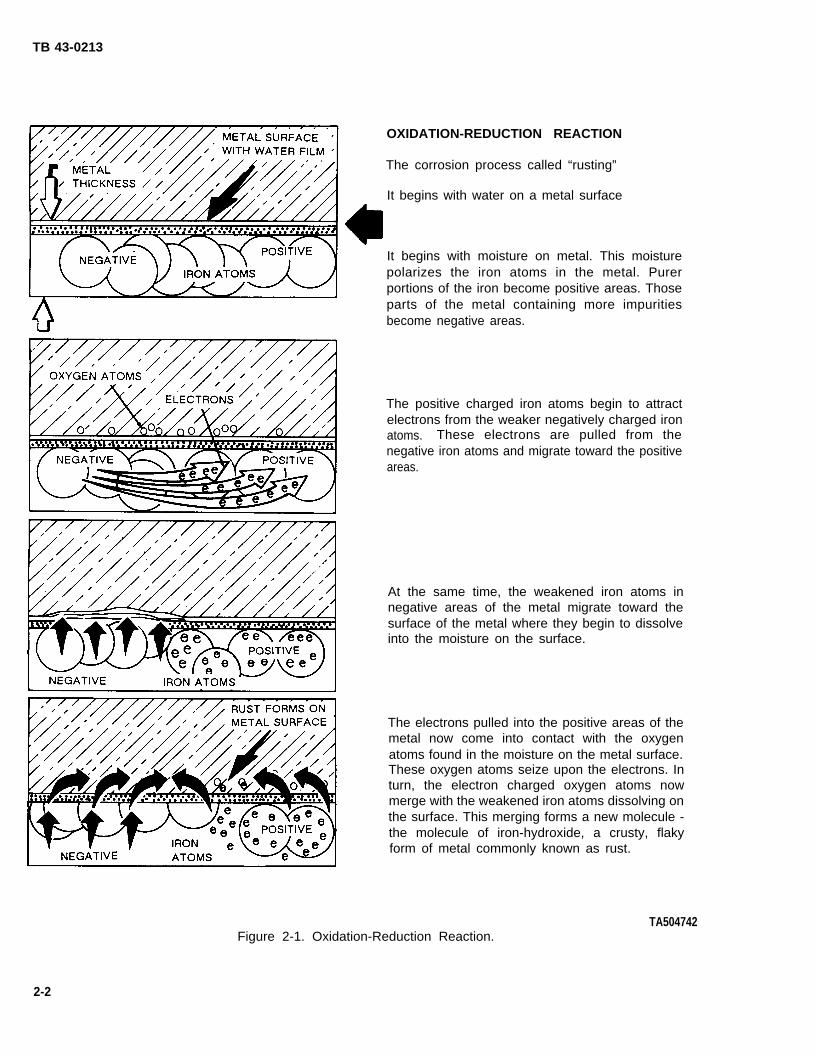
c. Rust is iron hydroxide. It is iron transformed by anatural process. This process is caused by the attractionof negatively charged electrons in the atoms of irontoward oxygen in water. Corrosion preventiontechnicians today refer to this natural process as the“Oxidation-Reduction Reaction” (see Figure 2-1).
d. The “Oxidation-Reduction Reaction” begins withwater on a metal surface as a result of exposure of themetal to rain, snow, dew, or humidity. This moistureforms a film on the metal. Beneath this film is the metalitself which, as noted above, is a formed, man-madeconstruction of earth minerals that have been stressedinto a shape that better suits mankind’s needs. Thatwhich was once an aggregate of iron ore in the earth’scrust has now been molted from its ore and molded intoa fender, stake pocket, or cargo bed.
e. The smelting process that makes iron is imperfectand the resultant metal itself always contains impurities,some areas of the metal more so than others. In the
presence of a moisture film, which serves as a conduc-tor, iron atoms in the purer areas of the metal create apositive electric pole while iron atoms in adjacent areaswith more impurities become the opposite pole, a nega-tive area. The result is similar to a simple electric bat-tery with moisture serving as the electrolyte, and thestronger-weaker iron atoms becoming the positive andnegative terminals of the circuit.
f. In the rusting process, iron atoms in the weaker,negative areas will split apart. These atoms give up orgive off some of their electrons, which are subatomicparticles found in all atoms. These lost electronsmigrate through the metal toward the positive area. As aresult of this loss, electron deficient iron atoms in thenegative area gravitate toward the metal surface anddissolve in the film of moisture. This half of the“Oxidation-Reduction Reaction”, or rusting process, isreferred to as the “oxidation half”. This half weakensthe metal in all negative areas, but it does not causerust. In order for actual rust to form, the second half ofthe “oxidation-reduction reaction” must complete thecycle.
g. The “reduction half” of the rusting process re-turns to the lost electrons migrating through the metaltoward the positive area. These free electrons arepicked up by oxygen atoms in the water film on the sur-face of the metal. On this surface, the products of thetwo reactions then combine to from a flaky, crusty thirdsubstance called iron hydroxide or rust. Stated anotherway, the dissolved electron deficient iron atoms thatgravitated to the wet surface during the oxidation half ofthe process have now combined with electron chargedoxygen atoms produced by the reduction half of theprocess. The result of all this is a transformation of ironatoms into iron hydroxide or rust.
h. The rusting process described above actuallybegins the moment moisture comes into contact withbare metal. This process is actually occurring at theatomic level; the results are not instantly apparent.While salt and dirt particles added to the moisture willaccelerate the process, it still takes weeks, months, oryears (depending upon the thickness of the metal) forthe process to transform the iron or steel to anunserviceable state.
2-1
TB 43-0213
OXIDATION-REDUCTION REACTION
The corrosion process called “rusting”
It begins with water on a metal surface
It begins with moisture on metal. This moisturepolarizes the iron atoms in the metal. Purerportions of the iron become positive areas. Thoseparts of the metal containing more impuritiesbecome negative areas.
The positive charged iron atoms begin to attractelectrons from the weaker negatively charged ironatoms. These electrons are pulled from thenegative iron atoms and migrate toward the positiveareas.
At the same time, the weakened iron atoms innegative areas of the metal migrate toward thesurface of the metal where they begin to dissolveinto the moisture on the surface.
The electrons pulled into the positive areas of themetal now come into contact with the oxygenatoms found in the moisture on the metal surface.These oxygen atoms seize upon the electrons. Inturn, the electron charged oxygen atoms nowmerge with the weakened iron atoms dissolving onthe surface. This merging forms a new molecule -the molecule of iron-hydroxide, a crusty, flakyform of metal commonly known as rust.
TA504742Figure 2-1. Oxidation-Reduction Reaction.
2-2
TB 43-0213
2-2. The Four Elements of Rusting.
a. Rusting of iron, steel, or any metal alloy is causedby the electrochemical reaction described in para-graph 2-1. This reaction is divided into four parts orelements:
(1) A positive reaction.
(2) A negative reaction.
(3) A path for negative particles to flow.
(4) A path for positive particles to flow.
b. In the explanation of the rusting process, thepositive and negative polarization of the iron atomsconstitute the first two elements. A path for positive andnegative particles to flow is described in the “oxidationhalf” of the “Oxidation-Reduction Reaction. ” If any ofthese elements are interrupted, the circuit is brokenand no rusting will occur.
c. The best means of breaking the rusting circuit isto bond a nonmetallic substance to the metal as abarrier between the metal and the environment. Tosome degree, paint accomplishes such a barrier. Onwell maintained exterior surfaces, paint will go a longway toward forestalling rust. But nothing can stoprusting altogether. Eventually, moisture will work itsway to the metal even beneath rustproofing material.
d. With a greater awareness of rust, the rustingprocess, the stages of rust, and rustproofing procedures,the damage of this form of corrosion can be minimizedwithin the Army to the point of zero impact upon theservice life of any Army vehicle.
2-3. The Four Stages of Rust.
a. Rust has been categorized into four distinctstages. These stages of deterioration have been stan-dardized within the Army in order to communicate thecondition of the metal. The four stages apply to paintedmetal surfaces:
NOTE
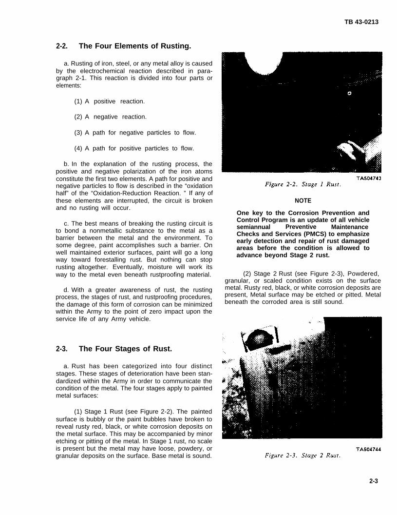
One key to the Corrosion Prevention andControl Program is an update of all vehiclesemiannual Preventive MaintenanceChecks and Services (PMCS) to emphasizeearly detection and repair of rust damagedareas before the condition is allowed toadvance beyond Stage 2 rust.
(2) Stage 2 Rust (see Figure 2-3), Powdered,granular, or scaled condition exists on the surfacemetal. Rusty red, black, or white corrosion deposits arepresent, Metal surface may be etched or pitted. Metalbeneath the corroded area is still sound.
(1) Stage 1 Rust (see Figure 2-2). The paintedsurface is bubbly or the paint bubbles have broken toreveal rusty red, black, or white corrosion deposits onthe metal surface. This may be accompanied by minoretching or pitting of the metal. In Stage 1 rust, no scaleis present but the metal may have loose, powdery, orgranular deposits on the surface. Base metal is sound.
2-3

TB 43-0213
(3) Stage 3 Rust (see Figure 2-4). Surfaceconditions and corrosion deposits present are similar toStage 2 except that metal in corroded area is unsound,and small pin holes may be present.
TA504745Figure 2-4. Stage 3 Rust.
(4) Stage 4 Rust (see Figure 2-5), Corrosionhas advanced to the point where the metal has beenpenetrated throughout. No metal remains at the pointof severest corrosion. There are holes in the surfacearea or metal is completely missing along the edges.
TA504746Figure 2-5. Stage 4 Rust.
b. Stages of rust are determined by visual inspectionas well as by knocking on the metal to determine metalsoundness. Probes, spring-loaded punches, or similardevices should be used if the soundness of the metal isin doubt.
2-4. Arresting Rust/Repairing Rust Dam-age.
a. Stage 1 and Stage 2 rust can be readily repaired.With Stage 3 rust, the metal is unbound and must becleared of rust and then reinforced, or the affected partmust be replaced entirely. Areas showing Stage 4 rustare not repairable. Such parts must be replaced.
b. Rust in Stages 1 and 2 can be removed by use ofan abrasive such as a sander, grinder, or wire brush,and/or by application of a rust removing compound.The best approach taken to remove rust dependsgreatly on the area being repaired as well as by suchconsiderations as metal thickness or accessibility of therusted area. A metal grinder, for example, would beincorrect for use on thin, short metal. Interior rust inlong boxed-in areas close to rubber molding (such asthe tube rails of a fold-down window) may require useof a wipe-off rust remover and swab as opposed to awash-off rust remover. Common sense and anunderstanding of the tools and materials available mustdetermine the best approach.
c. Whenever rust is located on a vehicle that cannotbe immediately repaired, the rust area should at least betreated with rust arresting coating, MIL-R-10036, toprevent further corrosion. Refer to paragraph 2-20 for adescription of this material, its application, andhazards.
d. Most Stage 1 and Stage 2 rust is localized and canbe easily removed. Larger areas may require use of highpressure washers. If repair is to be done immediately,application of the rust arresting coating (MIL-R-10036)is not necessary. Sand, grind, brush, and/or chemicallyremove the rust from the metal. Maintenancepersonnel should be aware of all chemical materialsavailable to assist in removing rust as well as any oils orchemicals on the metal. Paragraphs 2-19 through 2-28provide a list of these materials.
e. Stage 2 and Stage 3 rust are very similar inappearance. What qualifies rust as Stage 3 depends to agreat degree upon the thickness of the metal. Rustcould appear as more advanced on the heavy-gagedmetal of a cargo or dump body and yet be categorizedas Stage 2. What may appear as minor rust on sheetmetal may be Stage 3. The difference is in thesoundness of the metal. Inspectors looking at the firstexample of the cargo or dump body may determine byprobing and sounding that the metal beneath the rust isstill sound. Such rust would be classified as Stage 2.These same inspectors may determine that the lessvisible rust on the sheet metal has made that metalunbound ‘or unserviceable. The sheet metal rust,therefore, would be categorized as Stage 3.
f. Stage 3unserviceable.
and Stage 4 rust make the rusted partRepairing rust damage in such cases
2-4

requires replacement of the affected metal area. Insome instances, such as in the M151 series 1/4-Tontrucks, rust repair kits are available. For the most part,however, maintenance personnel should refer to thevehicle-specific TM for replacement parts.
g. Stage 3 and Stage 4 rusted metal parts classifiedas unserviceable should be removed. Adjacent areasshould be thoroughly cleaned of any rust, oils, orchemicals before replacement parts are installed.
NOTE
Army policy requires that all accessibleunder surfaces to be rustproofed must alsobe cleaned, primed, and painted. Thisadditional barrier of paint will providegreater protection to the metal.
h. Once the metal has been thoroughly cleaned,exterior surfaces must be primed and painted (seeTM 43-0139). All accessible under surfaces such as theunderbodies of cargo and dump trucks should also beprimed, painted, and allowed to dry before applyingrustproofing material. Surfaces that are not readilyaccessible for painting, such as boxed-in areas, arerustproofed only.
i. After the affected surface has been prepared,refer to the vehicle-specific chapters of this technicalbulletin for final rustproofing instructions (see Chapters4 through 22).
2-5. Rust-Prone Areas.
a. This technical bulletin provides specific rust-proofing instructions for most tactical vehicles as well asseveral commonly used trailers (see Tables 1– 1 and1-2). Application of rustproofing instructions can beapplied to all vehicles. To assist in adapting suchinstructions, this paragraph provides a list of rust-proneareas that are found in the design of most vehicles.Users are encouraged to recognize such areas andunderstand why such areas are prone to rust. Finally,users are encouraged to apply the principles ofrustproofing to all vehicles and trailers using thistechnical bulletin as a guide. The following are likelyareas for rust development:
(1) Channels (see Figure 2-6). A channel is anopen-ended design. It maybe square or C-shaped, suchas the rubrail support members of cargo and dumptruck sides and tailgates, or an inverted U-shape foundin the understructure of M191 series trucks. The
distinguishing
TB 43-0213
design characteristic of a channel is that itis open-ended. Insides of all channels should becleaned, treated and rustproofed. Exterior sides arecleaned, treated, primed and painted.
TA504747Figure 2-6. Channels.
(2) Rubrails (see Figure 2-7). Rubrails arechannels serving as both support members and asstructural protection for the vehicle body. Thehorizontal crossmember trimming the tops of all cargosides and tailgates are rubrails.
(3) Stiffeners (see Figure 2-7). Stiffeners areboxed-in or solid support members found in thetailgates of all cargo trucks. Stiffeners strengthen thecomponent to which they are attached. Solid stiffenersas found on most 2 1/2-Ton cargo trucks present littledifficulty regarding rust. Boxed-in stiffeners found onall 5-Ton trucks, however, are prone to trap moisture.
(4) Pockets (see Figure 2-8). Pockets aretube-like designs such as the stake pockets used toinstall the troop seat and side racks of cargo trucks.Pocket designs are typically fully open at the top of thetube. The bottom of the tube most often has a means ofdrainage from the tube. This is not always true oradequate, which makes pocket designs very vulnerableto rust as a result of trapped moisture.
(5) Tube Rails (see Figure 2-9). Tube railssuch as window frames of fold-down type windows orthe pillars of stationary windows are especially rust-prone due to the boxed-in design and the thin gage met-al most often used in their construction.
2-5

TB 43-0213
TA504748Figure 2-7. Rubrails and Stiffeners.
TA504749Figure 2-8. Pockets. Figure 2-9. Tube Rails.
TA504750
2-6

TB 43-0213
(6) Sills (see Figure 2-10). Sills are horizontalpanels beneath cab doors or along window frames ofsome vehicles. The horizontal framework beneathcargo and dump bodies are also sills. Sills may beboxed-in areas or open-ended horizontal frameworks.All sills are horizontal designs intended to bear theupright portions of the vehicle’s frame. Corrosionprotection of sill areas is essential.
TA504752Figure 2-11. Seams.
2-6. Preventive Maintenance for Rust-Prone Areas.
TA504751Figure 2-10. Sills.
(7) Seams (see Figure 2-11). Seams are areason the vehicle where separate pieces of metal cometogether. This is true whether the metals are weldedtogether or simply in contact with one another. Asidefrom seams working as areas where moisture collects,the differing metals will tend to contain greatervariations of impurities with respect to one another thanthose found in a single casting. This greater variation ofimpurities works to accelerate the metal polarizationsand the resultant rusting process.
b. Sections in this TB on rust-prone areas, generalpreparation procedures, and all basic information oncorrosion prevention equipment and materials may alsobe applied to nearly all vehicle rustproofing require-ments. The additional objective of this TB, however,does require good judgement and common sense on thepart of rustproofers. This is especially true with regardto drilling of access holes on heavy load-bearing areasof a vehicle. In such instances, comparable configura-tions within the vehicle-specific chapters of this TBprovide the best guidance.
a. With regard to the entire vehicle, but especiallyrust-prone areas, several steps have been developed toaid in rust prevention:
(1) Operators should wash their equipmentdaily with fresh water when operating in areas wheresalt is used to melt snow, or in areas where there is ahigh salt concentration in the air.
(2) Fiber or rubber floor mats should bepermanently removed from all tactical vehicles toprevent water from being trapped under mats. Suchtrapped water will cause floor pans to rust. All matsshould be removed and floorboards should be cleaned,repaired if needed, and sprayed with nonslip flight deckcovering compound, NSN 5610-00-782-5556.
(3) Drain holes, including drilled holes on theunderside of vehicles, should be kept clean and open toprevent moisture accumulation.
(4) In areas with high salt concentration in theair, canvas covers should be placed on static vehicles inmotor pools to reduce the amount of rain and mistentering crew and cargo compartments.
(S) Vehicles should be parked under shelterwhenever available.
2-7

TB 43-0213
(6) Vehicles and trailers treated with rustproof-ing materials should not be steam cleaned or cleanedwith solvent. Such cleaning may damage or dissolve theprotective rustproofing materials.
(7) When rust is found on equipment, therusted area should be promptly treated to preventfurther corrosion. Sand or grind the rusted area untilrust is removed from the metal. Then treat metal withany of the metal conditioners and/or rust removersdescribed in paragraphs 2-19 through 2-28 of this TB, ifthe surface will not be either painted or rustproofedimmediately after cleaning.primer and CARC paintsmetal, as appropriate.
{8) If possible, park
Spray cleaned metal withand/or rustproof cleaned
trailers on a slope to allowdrainage of water from the trailer. If operating a dumptruck, tilt the dump bed before vehicle shutdown toallow drainage of excess water.
(9) Vehicles with areas of Stage 1 or Stage 2rust should be cleaned of all existing rust. The cleanedarea should also be treated immediately with any of themetal conditioners and/or rust removers described inparagraphs 2-19 through 2-28 of this TB. Externalsurface areas should then be primed and painted.
b. The following is a list of common misunderstand-ings regarding rustproofing materials, applications, andtechniques:
(1) “Rustproofing” and “undercoating” are notthe same. Rustproofing is the application of a rustresistant and rust preventive material. This material isnot undercoating. Undercoating is a tar-like, sound-deadening material usually sprayed on the underside ofa vehicle at time of manufacture. The word also appliesto the action of applying the tar-like material itself.Undercoating is sometimes used to refer to theapplication of primer paints on metal bodies prior topainting the final coat. In neither instance isundercoating to be confused with rustproofing orrustproofing materials.
(2) Rustproofing is not permanent. The materi-al can be lost or destroyed. Tactical vehicles and trailerstreated with rustproofing materials should not be steamcleaned or cleaned with solvents. Such cleaning maydamage or dissolve the protective rustproofingmaterials.
(3) Rustproofing should never be applied overundercoating. In such instances, the material will belost as the undercoating flakes and falls from theunderside of the vehicle.
(4) Army policy requires that all accessibleunder surfaces to be rustproofed must be cleaned,primed, and painted. This policy differs fromcommercial practices. However, the additional barrierof paint will provide greater protection to the metal.
Section Il. OTHER TYPES OF CORROSION
2-7. General.
a. Rust accounts for the majority of corrosiondamage on U.S. Army vehicles, but other types ofcorrosion also limit the useful service life of equipment.Notable among these additional types of corrosion aregalvanic corrosion, pitting, poultice, and the effect ofthe sun and ozone. These and other types of corrosionare discussed in this section.
b. Two additional types of destructive factors aremildew and acid rain. While neither can be defined asforms of corrosion, they both contribute to corrosion.Both are destructive to Army equipment and,therefore, fall within the objectives of the CPCProgram. A better understanding of the causes andprevention of these factors will also assist inaccomplishing the overall goal of this technical bulletin.
2-8
2-8. Galvanic Corrosion.
a. Whenever two different metals come in contactwith each other, a potential exists for the corrosivedestruction of the atomically weaker of the two metals.The further away these two metals are in terms of theiratomic structure, the greater their potential for galvaniccorrosion. Table 2-1 provides a list of common metaland metal alloys. In this table, carbon is the hardest ofmetals and magnesium alloys are atomically theweakest. The closer the different metals are to oneanother in this table, the less is the potential for galvaniccorrosion. The actual galvanic corrosive process issimilar to rusting to the degree that weaker metalsbecome negative areas and lose electrons to thestronger positive atoms of the other metal.
b. The element carbon is included in the galvanictable of metals because this element is used to

TB 43-0213
strengthen some metal and is an agent in somelubricants. At the same time, carbon is highly cathodicto all metal alloys and is extremely corrosive when incontact with high potential end alloys as shown inTable 2-1.
c. Galvanic corrosion is sometimes desirable as inthe case of galvanized steel. This is steel with a zinccoating. The zinc coating protects the steel by serving asa barrier between the shell and the corrosive world. Thezinc coating also serves as a sacrificial metal due to thegalvanic process whereby the natural corrosion processconcentrates on the weaker zinc to the benefit of thesteel. Maintenance technicians must keep galvaniccorrosion in mind whenever replacing nuts, bolts, metalscrews, clamps, etc. These bin items should alwaysapproximate the metals they will come in contact withon the vehicle.
2-9. Ozone and Ultraviolet Radiation.
a. Ozone is a blue, gaseous form of oxygen formednaturally in our atmosphere by the effects of lightingand/or by normal oxygen’s exposure to ultravioletradiation from the sun. From the high atmospherewhere it is concentrated, the ozone falls to earth. Ozoneis the primary enemy of tires and other rubberproducts. It destroys the two most important propertiesof rubber, its strength and elasticity. Ozone exposuredries out rubber so that it becomes brittle and easilyworn through. Ozone oxygen atoms exist in greaterquantities on hot, desert-like surfaces of the earthwhere their effects on tires, rubber seals, and otherautomotive products are most pronounced. Most Armytires and other rubber products are manufactured withozone preservatives, but these qualities are lost withtime and exposure. Commercial preservatives such asArmor All or Agemaster can be applied as required.
b. Ultraviolet radiation is a corrosive agent.Ultraviolet radiation is everywhere in the rays of thesun. Aside from contributing to the formation of ozone,ultraviolet radiation breaks down paints and resins. Italso breaks down the polymer bonds or chemicalstructures of rubbers and plastics. With prolongedexposure to direct sunlight, these materials will losetheir strength, dry out, and crack. If prolongedexposure to ultraviolet radiation cannot be avoided,provide a preventive maintenance watch on all suchproducts and periodic replacement, as necessary.Rubber products may be protected using commercialpreservatives. Shelter should also be used wheneverpossible to forestall the effects of ultraviolet radiation.
2-10. Pitting Corrosion.
a. Pitting occurs most commonly on aluminum andstainless steel products. It is a form of localizedcorrosion in which small areas of the metal corrodepreferentially to the adjacent areas. This type ofcorrosion causes cavities or pits in the metal surface.
b. The cause of pitting corrosion is salt, eitherintroduced through sea water or on the highway inwinter months. To avoid pitting, clean the vehicle afterexposure to salt as soon as is practical.
2-11. The Differential Aeration Effect.
a. Air carries moisture but also dries moisture fromthe surface of metals. Whenever the design of thevehicles is such that moisture can become trapped,while areas immediately surrounding the trappedmoisture are ventilated and, therefore, quickly dried,the difference between the two metal areas (onedry/one moist) will set up an electrochemical cell. Theresult will be an intense acceleration of the rustingprocess and an intense, localized corrosion. Thisdynamic is called the “differential aeration effect”which can be translated into the phrase “result ofdiffering ventilation”.
b. Crevice corrosion in rocker panels is the mostcommonly cited example of the differential aerationeffect. This dynamic is also responsible for poulticecorrosion (see paragraph 2-12).
2-12. Poultice Corrosion.
Poultice corrosion is rust which occurs when depositsof mud or other debris hold stagnant moisture incontact with a metal surface. Because the mud or debrisis moisture-laden, this condition accelerates the rustingprocess. As with pitting corrosion, the solution is tokeep the vehicle as clean as possible at all times.
2-13. Crevice Corrosion.
Crevice corrosion is caused by a design problem thatmanufacturers are being asked to keep in mind duringthe planning of new vehicles. Crevice corrosion isintense accelerated rusting in joints and recesses. It iscaused by the differential aeration effect outlinedabove. The solution for crevice corrosion is rustproof-ing of the joint or recess.
2-9

TB 43-0213
Table 2-1. The Galvanic Corrosion Potentiai of Different Metais.
Magnesium AlloysBeryllium
ZincGalvanized Steel
High PotentialEnd
Low PotentialEnd
Aluminum AlloysChromium
GalliumCadmium
Mild SteelWrought Iron
IridiumLow-Alloy Steels
Cast IronLow-Alloy Cast Iron
4-6% Cr SteelNi Cast Iron
12-14% Chromium Steel and 25-30%Lead-Tin Solders
16-18% Chromium SteelAustenitic Cr-Ni Stainless Steel
Austenitic Cr-Ni-Mo StainlessLead
TinManganese Bronze
Naval BrassCobalt
Nickelinconel (13%
Yellow BrassAdmiralty Brass
Aluminum BronzeRed Brass
Ant imonyCopper
Silicon BronzeNickel Silver
70-30 Copper NickelTitanium
Monel
Cr 6.5% Fe, Bal. Ni)
Composition G Bronze (88% Cu, 2% Zn, 10% Sn)Composition M Bronze (88% Cu, 3% Zn, 6.5% Sn, 1.5% Pb)
Silver SolderNickel (Passive)
70-30 Nickel CopperStainless Steels (Passive)
SilverPalladium
GoldRhodium
PlatinumCarbon
CATHODIC
2-10

TB 43-0213
2-14. Stress Corrosion Cracking.
Almost all rusting is a form of stress corrosionbecause man-made iron or steel is a stressed by-productof natural ores. Stress corrosion is most often associatedwith metals or rubbers under even greater stress due tothe design application. Steel forced by loads into a bendis an example. If such steel is exposed further to rusting,it becomes structurally weaker. The result is a raising ofthe level of stress placed on the metal; the greater thestress, the more the corrosion acts upon the metal. Inheavy metals such as steel, the effects of stresscorrosion are one of the causes of metal fatigue. Inother applications, stress corrosion will cause crackingalong with an increase of stress and acceleratedcorrosion.
2-15. Fretting Corrosion.
This is a form of stress corrosion. It is caused byfriction of the metal against other surfaces duringtransportation and handling, especially if the metalproduct is not well secured, thereby causing shiftingduring movement. The resultant friction may wear awayat the metal’s protective film. In the presence ofmoisture, it will also accelerate the corrosion process.The result will be pitting or stress corrosion inducedcracks.
2-16. Mildew.
Although mildew is not strictly corrosion, it doescontribute to corrosion in metals and is very destructiveto other Army products. Mildew is a gradual deteriora-tion of organic material such as canvas or tarpaulincaused by the growth of fungus on or in the material.This growth occurs if the canvas or tarpaulin is left
damp and unattended or left for prolonged periods in adamp shelter. Canvas is a heavy, coarse, and closelywoven fabric of cotton, kemp, or flax. Tarp or tarpaulinis coarse linen. Both of these fabrics are organic materi-als and, as such, keeping them clean and allowing themto air out will prevent the formation of mildew.
2-17. Acid Rain.
a. Acid rain is commonly understood as thebombardment of the earth by chemical wastes fromindustry. It is viewed as a major problem in heavilypopulated and industrial areas. Wherever there are oilburning furnaces or chemical mills in use, there will beemissions which are felt to be the cause of acid rain.Acid rain is chiefly composed of dimethyl sulfide andhydrogen sulfide. The chemicals attack painted metalsurfaces causing pitting and cracks. This is not a majorcorrosion factor, however, since scheduled cleaning ofthe affected vehicle will nullify the effects of thechemicals.
b. Acid rain is also caused by marshy areas such asswamps or bogs which naturally produce dimethylsulfide and hydrogen sulfide through the decaying ofmatter. Again, the solution is to keep vehicles as cleanas possible at all times.
2-18. Corrosion Caused by Oils, Chemicals,and Gases.
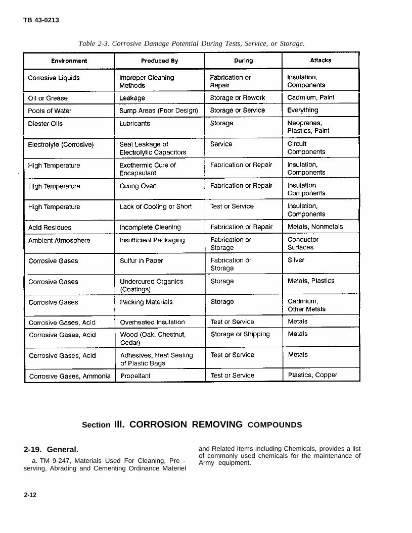
Corrosion can occur when metal comes in contactwith various substances. This contact may occur duringthe repair, testing, or shipment of a vehicle. Tables 2-2and 2-3 list corrosive solvents and their effect onmetallic surfaces.
Table 2-2. The Corrosive Effects of Fuel Oil, Coolants, and Other Fluids.
2-11
TB 43-0213
Table 2-3. Corrosive Damage Potential During Tests, Service, or Storage.
Section Ill. CORROSION REMOVING COMPOUNDS
2-19. General. and Related Items Including Chemicals, provides a list
a. TM 9-247, Materials Used For Cleaning, Pre -of commonly used chemicals for the maintenance ofArmy equipment.
serving, Abrading and Cementing Ordinance Materiel
2-12
TB 43-0213
b. Those materials that most closely relate toCorrosion Prevention and Control Programprovided below.
theare
2-20. Rust Arresting Coating (MIL-R-10036).
a. This is a clear liquid composed of dryng andsemi-drying oils and driers. This compound is dilutedwith a petroleum solvent to a brush or sprayconsistency.
b. The compound will set to touch in three hoursand dry to a hard film in 24 hours. It is used on rustedmetal and painted surfaces to arrest further corrosion.
2-21. Cleaning Compound Solvent: De-creasing and Self-Emulsifying (MIL-S-11090A).
a. This compound is a liquid solvent containing anemulsifying agent or agents. It is used to remove oils,greases, asphalts, tars, and preservative compoundsfrom metallic and painted surfaces. It will not removewax-type rust preventive compounds.
b. The solvent is used full strength and is applied bybrush, swab, soak, or spray followed by rinsing with ajet of steam or water. If water must be avoided, rinsewith dry cleaning solvent (P-S-661).
2-22. Corrosion Removing Compound: Al-kaline Immersion (Oral JR-OME-PD-110A).
WARNING
Due to the large quantity of caustic soda(lye), do not add large amounts of the com-pound to the water at one time, since thereaction may generate enough heat tocause an eruption. Protective clothing andglasses should be worn when using or mak-ing this solution. In case of contact with skinor eyes, flush immediately and thoroughlywith water for at least 20 minutes. Get medi-cal attention.
a. This compound is a dry powder or fine granularmaterial, or both, in combination with flake material.This compound is free from alkali metal cyanide.
b. It is used to remove rust and scale from iron andsteel components such as engine blocks, cylinderheads, and miscellaneous engine parts. It can also beused to remove paint, heavy grease, oil, and phosphatecoatings. This should be accomplished in a separatetank.
2-23. Corrosion Removing Compound: Hy-drochloric Acid w/inhibitor (MIL-A-13528) (ORD).
WARNING
Phosphine, (hydrogen phosphide), a color-less, poisonous gas, forms very readilywhen any mineral acid reacts with metals oralloys containing phosphorus. Adequateventilation must be provided since this gasis a dangerous fire, explosive, and toxic haz-ard. This acid causes burns. Avoid breath-ing vapors. in case of contact with skin oreyes, flush immediately and thoroughly withwater for at least 20 minutes. Get medicalattention.
a. This is an acid-pickling compound composed ofhydrochloric (muriatic) acid and an inhibiting materialthat limits the action of the acid on the. base metal afterthe rust has been removed.
b. The compound as issued is ready for use. It isused to remove heavy rust deposits from ferrous metalparts such as bomb fins, engine blocks, and small armsmateriel. This compound does not change thedimensions of the parts materially, if properly applied.
2-24. Corrosion Removing Compound:Metal Conditioner and Rust Remover,Phosphoric-Acid Type.
WARNiNG
This compound contains a strong acid. Caremust be taken to prevent contact with skinor eyes. Protective clothing and glassesshould be worn when making up or usingthe solution. in case of contact, flush skinand affected areas immediately and thor-oughly with water for at least 20 minutes.Get medical attention.
a. This compound is a clear, homogeneous,uninhibited phosphoric acid solution containing a
2-13

TB 43-0213
wetting agent. This compound does not contain a greasesolvent because it is a de-ruster for parts that have beenprecleaned.
b. This compound is used to remove rust fromprecleaned metal parts.
2-25. Corrosion Removing Compound:Metal Conditioner and Rust Remover,Wash-off Type (MIL-M-10578A,Type l).
WARNING
When diluting the compound, pour thecompound into the water. Do not pour waterinto the compound. Phosphine, (hydrogenphosphide), a colorless, poisonous gas,forms very readily when any mineral acidreacts with metals or alloys containingphosphorus. Since this gas is a dangerousfire, explosive, and toxic hazard, adequateventilation must be provided. The amountof phosphine released from the acid bathincreases with an increase in temperatureand concentration of acid. Compoundcontains a strong acid. Operators shouldwear protective clothing and glasses whenmaking up or using this compound. Ifsplashed on skin or eyes, flush immediatelyand thoroughly with water for at least20 minutes. Get medical attention. Avoidprolonged breathing of vapors.
CAUTION
Do not use this compound on electricalwiring, coil steel springs, or other springsteels.
a. This compound is a concentrated, homogeneous,stable liquid, containing free orthophosphoric acid andwater soluble, nontoxic, organic grease solvents.
b. This compound is used to remove rust and greasefrom ferrous metal surfaces, and provides a slightetching action for ferrous and nonferrous metals topromote the adhesion of paint or corrosive preventives.
2-26. Sodium Bichromate, Dihydrate: Tech-nical, Granular (O-S-595).
This compound consists of red crystals that aresoluble in water. It is used in the following applications:
a. As a component of low temperature bichromatefinish solution for ferrous metals.
b. As a molten bath to produce black finish oncorrosion resisting steel.
c. As a component of a chromate pickle solutionused to clean traces of flux from magnesium alloy itemsafter gas welding.
d. As a component of a chromate pickle bath fortreating magnesium alloy sand mold, permanent mold,and die castings and wrought magnesium alloy parts toprotect them against corrosion (see MIL-M-3171A).
e. As a component of a chrome pickle solution fortreatment of magnesium alloy parts before painting (seeMIL-M-3171A).
f. As a component of a galvanic anodizing solutionthat is used in Type IV treatment of magnesium alloyparts before painting (see MIL-M-3171A).
g. As a component of a neutralizing bath fortreating magnesium alloy parts after Type V corrosionprotective treatment and before painting.
2-27. Corrosion Removing Compound:Metal Conditioner and Rust Remover,Wipe-off TypeType II).
WARNING
Pour the compound into the
(MIL-M-10578A,
water. Do notpour the water into the compound. Phos-phine, (hydrogen phosphide), a colorless,poisonous gas, forms very readily when anymineral acid reacts with metal or alloyscontaining phosphorus. Since this gas is adangerous fire, explosive, and toxic hazard,adequate ventilation must be provided.
CAUTION
Do not apply this cleaner to electricalwiring, steel coil springs, or other springsteel. The treated surfaces must be paintedor coated with corrosion preventive com-pound as soon as possible.
a. This compound is a dilute solution of orthophos-phoric acid and water soluble, organic, nontoxic, greasesolvents. The acid is in lesser proportion and the greasesolvents in greater proportion than in the wash-off type.
b. It is used to remove light or medium grease andrust deposits from ferrous metals, or to conditionferrous, galvanized, brass, or aluminum surfaces forpainting. The remaining film of gray-white ironphosphate conditions the surface for paint.
2-14

TB 43-0213
2-28. Detergent General Purpose: Powder contains no abrasives or fatty-acid soaps, and is not
(P-D-220D). irritating to the skin.
a. This is a cleaning agent in powder form consisting b. It is used to remove grease, oil, and occupationalessentially of synthetic detergents. It is soluble in hard, soiI from painted surfaces, and in general soil removal.soft, and salt water. It is free from objectionable odors, It is applied with brush, cloth, or sponge.
2-15/(2-16 Blank)
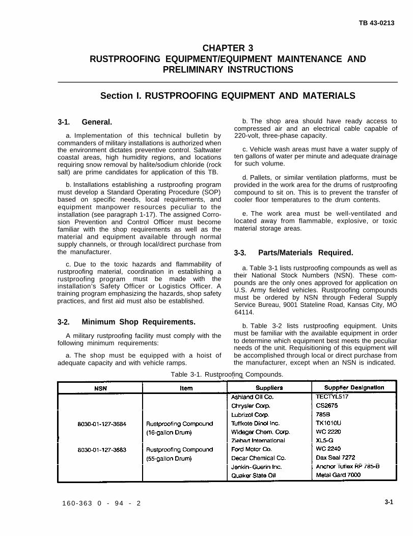
TB 43-0213
CHAPTER 3RUSTPROOFING EQUIPMENT/EQUIPMENT MAINTENANCE AND
PRELIMINARY INSTRUCTIONS
Section I. RUSTPROOFING EQUIPMENT AND MATERIALS
3-1. General.
a. Implementation of this technical bulletin bycommanders of military installations is authorized whenthe environment dictates preventive control. Saltwatercoastal areas, high humidity regions, and locationsrequiring snow removal by halite/sodium chloride (rocksalt) are prime candidates for application of this TB.
b. Installations establishing a rustproofing programmust develop a Standard Operating Procedure (SOP)based on specific needs, local requirements, andequipment manpower resources peculiar to theinstallation (see paragraph 1-17). The assigned Corro-sion Prevention and Control Officer must becomefamiliar with the shop requirements as well as thematerial and equipment available through normalsupply channels, or through local/direct purchase fromthe manufacturer.
c. Due to the toxic hazards and flammability ofrustproofing material, coordination in establishing arustproofing program must be made with theinstallation’s Safety Officer or Logistics Officer. Atraining program emphasizing the hazards, shop safetypractices, and first aid must also be established.
3-2. Minimum Shop Requirements.
A military rustproofing facility must comply with thefollowing minimum requirements:
a. The shop must be equipped with a hoist ofadequate capacity and with vehicle ramps.
b. The shop area should have ready access tocompressed air and an electrical cable capable of220-volt, three-phase capacity.
c. Vehicle wash areas must have a water supply often gallons of water per minute and adequate drainagefor such volume.
d. Pallets, or similar ventilation platforms, must beprovided in the work area for the drums of rustproofingcompound to sit on. This is to prevent the transfer ofcooler floor temperatures to the drum contents.
e. The work area must be well-ventilated andlocated away from flammable, explosive, or toxicmaterial storage areas.
3-3. Parts/Materials Required.
a. Table 3-1 lists rustproofing compounds as well astheir National Stock Numbers (NSN). These com-pounds are the only ones approved for application onU.S. Army fielded vehicles. Rustproofing compoundsmust be ordered by NSN through Federal SupplyService Bureau, 9001 Stateline Road, Kansas City, MO64114.
b. Table 3-2 lists rustproofing equipment. Unitsmust be familiar with the available equipment in orderto determine which equipment best meets the peculiarneeds of the unit. Requisitioning of this equipment willbe accomplished through local or direct purchase fromthe manufacturer, except when an NSN is indicated.
Table 3-1. Rustproofing Compounds.
160-363 0 - 94 - 2 3-1

TB 43-0213
Table 3-2. Rustproofing Equipment.
3-2
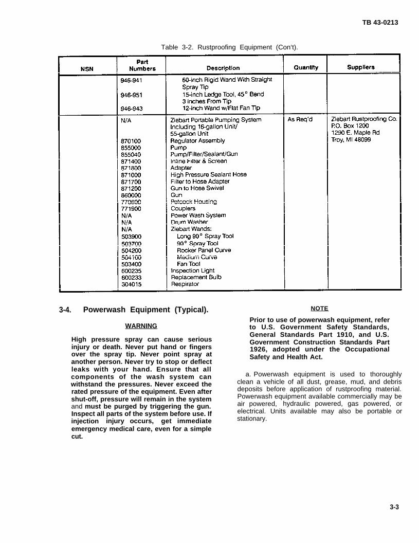
TB 43-0213
Table 3-2. Rustproofing Equipment (Con‘t).
3-4. Powerwash Equipment (Typical). NOTE
Prior to use of powerwash equipment, referWARNING to U.S. Government Safety Standards,
High pressure spray can cause seriousGeneral Standards Part 1910, and U.S.Government Construction Standards Part
injury or death. Never put hand or fingers 1926, adopted under the Occupationalover the spray tip. Never point spray at Safety and Health Act.another person. Never try to stop or deflectleaks with your hand. Ensure that allcomponents of the wash system can a. Powerwash equipment is used to thoroughly
withstand the pressures. Never exceed the clean a vehicle of all dust, grease, mud, and debris
rated pressure of the equipment. Even after deposits before application of rustproofing material.
shut-off, pressure will remain in the system Powerwash equipment available commercially may be
and must be purged by triggering the gun. air powered, hydraulic powered, gas powered, or
Inspect all parts of the system before use. If electrical. Units available may also be portable or
injection injury occurs, get immediate stationary.
emergency medical care, even for a simplecut.
3-3
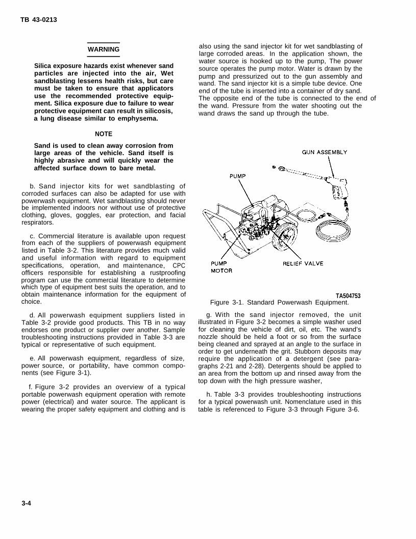
TB 43-0213
WARNING
Silica exposure hazards exist whenever sandparticles are injected into the air, Wetsandblasting lessens health risks, but caremust be taken to ensure that applicatorsuse the recommended protective equip-ment. Silica exposure due to failure to wearprotective equipment can result in silicosis,a lung disease similar to emphysema.
NOTE
Sand is used to clean away corrosion fromlarge areas of the vehicle. Sand itself ishighly abrasive and will quickly wear theaffected surface down to bare metal.
b. Sand injector kits for wet sandblasting ofcorroded surfaces can also be adapted for use withpowerwash equipment. Wet sandblasting should neverbe implemented indoors nor without use of protectiveclothing, gloves, goggles, ear protection, and facialrespirators.
c. Commercial literature is available upon requestfrom each of the suppliers of powerwash equipmentlisted in Table 3-2. This literature provides much validand useful information with regard to equipmentspecifications, operation, and maintenance, CPCofficers responsible for establishing a rustproofingprogram can use the commercial literature to determinewhich type of equipment best suits the operation, and toobtain maintenance information for the equipment ofchoice.
d. All powerwash equipment suppliers listed inTable 3-2 provide good products. This TB in no wayendorses one product or supplier over another. Sampletroubleshooting instructions provided in Table 3-3 aretypical or representative of such equipment.
e. All powerwash equipment, regardless of size,power source, or portability, have common compo-nents (see Figure 3-1).
f. Figure 3-2 provides an overview of a typicalportable powerwash equipment operation with remotepower (electrical) and water source. The applicant iswearing the proper safety equipment and clothing and is
also using the sand injector kit for wet sandblasting oflarge corroded areas. In the application shown, thewater source is hooked up to the pump, The powersource operates the pump motor. Water is drawn by thepump and pressurized out to the gun assembly andwand. The sand injector kit is a simple tube device. Oneend of the tube is inserted into a container of dry sand.The opposite end of the tube is connected to the end of the wand. Pressure from the water shooting out thewand draws the sand up through the tube.
TA504753Figure 3-1. Standard Powerwash Equipment.
g. With the sand injector removed, the unitillustrated in Figure 3-2 becomes a simple washer usedfor cleaning the vehicle of dirt, oil, etc. The wand’snozzle should be held a foot or so from the surfacebeing cleaned and sprayed at an angle to the surface inorder to get underneath the grit. Stubborn deposits mayrequire the application of a detergent (see para-graphs 2-21 and 2-28). Detergents should be applied toan area from the bottom up and rinsed away from thetop down with the high pressure washer,
h. Table 3-3 provides troubleshooting instructionsfor a typical powerwash unit. Nomenclature used in thistable is referenced to Figure 3-3 through Figure 3-6.
3-4

TB 43-0213
TA504754
Figure 3-2. Powerwash Operation (Typical).
Figure 3-3. Pump Assembly (Typical).
3-5

TB 43-0213
3-5. Material Pumps (Typical).
a. Pumps used in the application of rustproofingmaterial are high pressure, air driven motors that mountdirectly onto the rustproofing material drum, Acomplete unit consists of the air motor or pump itself aswell as attaching air regulator, pressure gage, in-line airfilters, a bleed-type master air valve, material filter, andgrounding log.
b, Commercial literature is available upon requestfrom each of the supplies of material pumps listed inTable 3-2, CPC officers will benefit from this literaturewhen determining which pump best suits theiroperation. This literature also provides specificmaintenance and repair instructions. Figure 3-7illustrates a typical material pump, This figure isrepresentative only and is not intended to endorse oneproduct or supplier over another.
c. The air motor pump consists of the air motor andpiston cylinder. The assembly rests on a drum topped
with the cylinder end immersed in the rustproofingmaterial. The air regulator and pressure gage most oftenattaches directly into the motor lead. The regulatorcontrols the air pressure going into the pump, therebyalso controlling the pump speed.
WARNING
All material pump air lines must be purgedof air pressure after operation. Failure to doso could cause the pump to cycle unexpect-edly. Serious material injection injury couldresult.
d. To ensure the safe operation of the pump, an airbleed valve must be installed to purge the system ofpressurized air after operation. This bleed valve may bebuilt into the air regulator and gage, or may be aseparate item, depending on the supplier.
TA504756Figure 3-4. Pump Motor Assembly (Typical).
3-6

TB 43-0213
e. The material pump system should also include an f. Grounding of the system during operation isin-line air filter to remove dirt and moisture from the essential due to the potential for a buildup of staticcompressed air going into the pump, as well as an air electricity. During operation, the pump, the spray gun,line oiler which automatically lubricates the air motor and the object being rustproofed should each be wellduring operation. These items are attached to the air grounded to eliminate the fire/explosive hazard of staticlines going into the purge valve and air regulator, which electricity in proximity to rustproofing material.are attached directly onto the pump. The compressedair source is a minimum shop requirement (seeparagraph 3-2).
Figure 3-5. Powerwash Spray Gun (Typical).TA504757
3-7
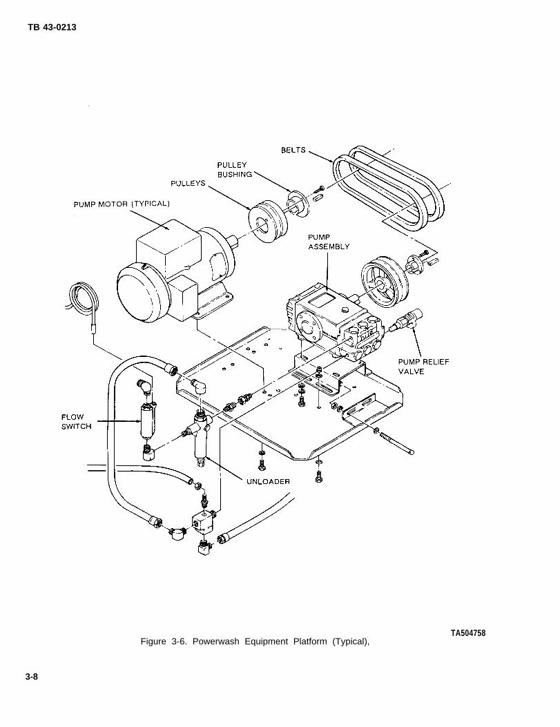
TB 43-0213
Figure 3-6. Powerwash Equipment Platform (Typical),TA504758
3-8
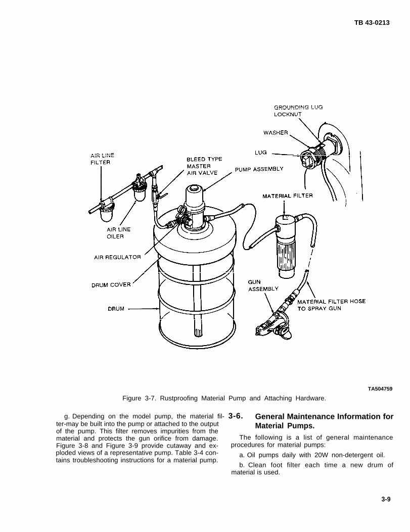
TB 43-0213
TA504759
Figure 3-7. Rustproofing Material Pump and Attaching Hardware.
g. Depending on the model pump, the material fil- 3-6. General Maintenance Information forter-may be built into the pump or attached to the output Material Pumps.of the pump. This filter removes impurities from thematerial and protects the gun orifice from damage. The following is a list of general maintenanceFigure 3-8 and Figure 3-9 provide cutaway and ex- procedures for material pumps:ploded views of a representative pump. Table 3-4 con-tains troubleshooting instructions for a material pump.
a. Oil pumps daily with 20W non-detergent oil.
b. Clean foot filter each time a new drum ofmaterial is used.
3-9

TB 43-0213
c. Clean material line filter every two weeks.
d. If slide valve freezes, use antifreeze through theair intake to thaw out. Ensure that it is frozen and notsimply stuck because of lack of lubrication.
e. Never operate the pump at more that 100 psi(690 kPa). You will damage the piston within the pumpshaft.
f. If pump fails to operate, do not strike pump withhammer, etc.
g. Never allow the pump to run dry. A dry pump willquickly accelerate to a high speed, possibly damagingitself.
h. Always flush the unit before material hardens inany part of the system. How often flushing occursdepends upon the material being used. Use the lowestpossible pressure to flush. Ground spray gun againstwaste container.
i. After spraying, always turn off the air at its sourceand purge the line using the air bleed valve. Disconnectthe air line coupler after the line has been cleared. Atthe output end, trigger the gun into a waste container toclear it of material under pressure. Engage the triggersafety and disconnect the material line at the filter.Clean gun and line.
NOTE
If the grounding wire was disconnectedbefore servicing, be sure to reconnectit before operating the pump.
TA504760Figure 3-8. Typical Pump
(Cutaway View).
3-10
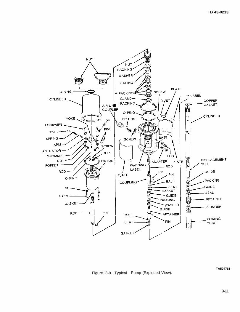
TB 43-0213
Figure 3-9. Typical Pump (Exploded View).TA504761
3-11

TB 43-0213
3-7. Spray Guns. b. There are two types of material spray gunsavailable on the market (see Figure 3-10):
WARNING
High pressure spray equipment can causeserious injury or death. Never put hand orfingers over spray tip. Never point spray gunat another person. Never try to stop ordeflect leaks with your hand. Ensure that allcomponents of the spray system canwithstand the pressures. Never exceed therated pressure of the equipment. Neveralter or modify the equipment. Even aftershut-off, pressures will remain in thematerial hose and gun and must be purgedby grounding the gun to a waste containerand triggering the gun. Never changewands, tips, or any accessories until aftersystem is completely shut off and purged.Inspect all parts of the system before use.Ensure that all fittings are properly installedand tightened, and that hoses are not frayedor cracked. If injection injury occurs, evenfor a simple cut, get immediate emergencymedical care. Inform emergency physiciansthat the material injected into the skin is apetroleum compound containing aliphaticpetroleum naphtha with an effect similar tokerosene.
NOTE
Prior to use of high pressure sprayequipment, refer to U.S. GovernmentSafety Standards, General Standards Part1910, and U.S. Government ConstructionStandards Part 1926, adopted under theOccupational Safety and Health Act.
a. A rustproofing material spray gun is used tocontrol and direct the spray of the material, or to stopthe spray by releasing the trigger. These spray guns areused in combination with various wands that permit thetechnician to reach out-of-way places and to applydifferent spray patterns.
(1) Fogging Gun. The fogging gun connects theair source directly to the gun along with the rustproofingmaterial. The pressurized air and material convergewithin the gun where, when the trigger is pulled, theyare ejected in a fine mist. This type of rustproofing .application is called fogging and is NOT approved foruse by U.S. Army installations.
TA504762Figure 3-10. Fogging and Airless
Spray Guns.
NOTE
Depending on the installation, the spray gunhandle may be equipped with a Z swivel toprovide greater maneuverability.
(2) Airless Gun. The airless type of spray gunsystem uses an air motor pump over the drum asdiscussed in paragraph 3-5. The material pressurizedout of the pump, through the material filter, and intothe gun is not mixed with air. As a result, the materialejected from the wand end is a pure concentration ofrustproofing material.
3-12

TB 43-0213
Table 3-3. Troubleshooting Powerwash Equipment.
3-13
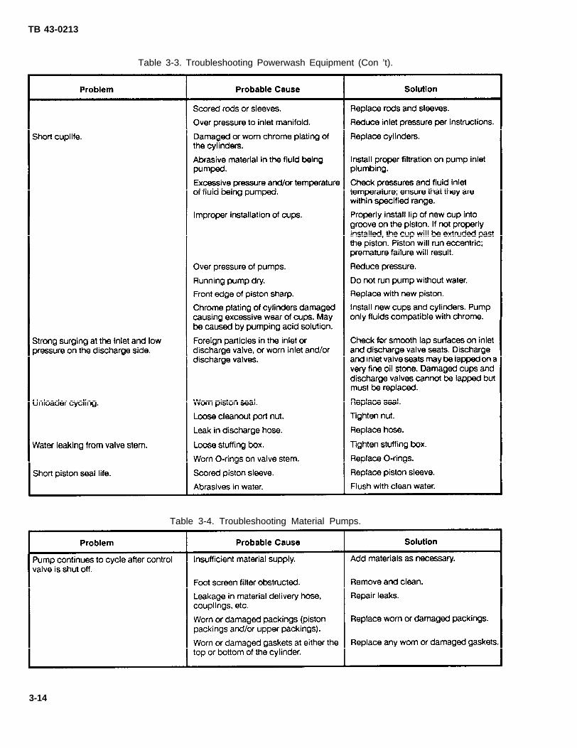
TB 43-0213
Table 3-3. Troubleshooting Powerwash Equipment (Con ’t).
Table 3-4. Troubleshooting Material Pumps.
3-14

TB 43-0213
Table 3-5. Troubleshooting Material Pumps (Con’t).
c. Commercial literature is available upon request e. The following is a typical installation procedurefrom each of the suppliers of material spray guns,wands, and attaching hardware and hoses, as listed inTable 3-2. This available literature also providesspecific maintenance and repair instructions.Figure 3-11 is an example of a typical spray gun system.
d. There are two ways of mounting material filters tothe system (see Figure 3-12 and Figure 3-13). There isno difference in performance from one mountingposition to another; however, with remote mounting,the added weight on the hose reduces the ease ofhandling and increases the chance of damaging thefilter.
for a rustproofing material spray gun system:
WARNING
Make certain pump motor is turned off andall air lines have been purged of pressurebefore installing spray gun assembly.
(1) Connect the material filter to the outputport of the air motor pump, directly or remotely,depending on the model.
3-15

TB 43-0213
NOTE
TA504763Figure 3-11. Typical Spray Gun System.
TA504764Figure 3-12. Material Filter
(Remote Mounting).
In some shop applications, it may bedesirable to operate two spray guns fromthe same material pump. In such instances,a tee may be used at the outlet port of thematerial filter instead of a direct materialhose connection. The multiple materialhoses are then connected to the two outletparts of the tee.
(2) Connect the material hose (black hose) tothe outlet port of the material filter.
(3) Connect the opposite end of the materialhose to the handle of the gun(s).
TA504765Figure 3-13. Material Filter
(Direct Mounting).
NOTE
Depending on the installation, the spray gunhandle may be equipped with a Z swivel toprovide greater maneuverability.
f. Once the spray gun system has been connected, .refer to paragraph 3-8 for information concerningchoice of wands, wand extensions, and assembly to thespray gun.
3-16
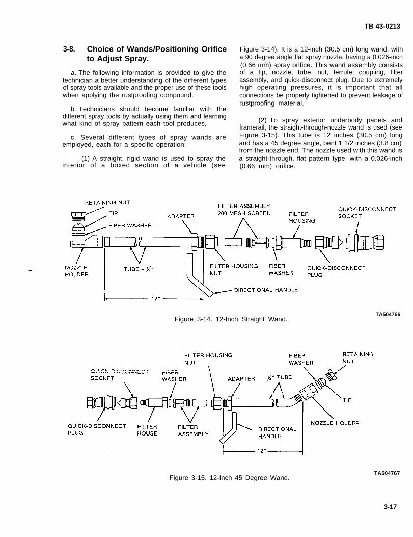
TB 43-0213
3-8. Choice of Wands/Positioning Orificeto Adjust Spray.
a. The following information is provided to give thetechnician a better understanding of the different typesof spray tools available and the proper use of these toolswhen applying the rustproofing compound.
b. Technicians should become familiar with thedifferent spray tools by actually using them and learningwhat kind of spray pattern each tool produces,
c. Several different types of spray wands areemployed, each for a specific operation:
(1) A straight, rigid wand is used to spray theinterior of a boxed section of a vehicle (see
Figure 3-14). It is a 12-inch (30.5 cm) long wand, witha 90 degree angle flat spray nozzle, having a 0.026-inch(0.66 mm) spray orifice. This wand assembly consistsof a tip, nozzle, tube, nut, ferrule, coupling, filterassembly, and quick-disconnect plug. Due to extremelyhigh operating pressures, it is important that allconnections be properly tightened to prevent leakage ofrustproofing material.
(2) To spray exterior underbody panels andframerail, the straight-through-nozzle wand is used (seeFigure 3-15). This tube is 12 inches (30.5 cm) longand has a 45 degree angle, bent 1 1/2 inches (3.8 cm)from the nozzle end. The nozzle used with this wand isa straight-through, flat pattern type, with a 0.026-inch(0.66 mm) orifice.
Figure 3-14. 12-Inch Straight Wand.TA504766
Figure 3-15. 12-Inch 45 Degree Wand.TA504767
3-17

TB 43-0213
(3) Another type isFigure 3-16, A). This wandlong, and is used primarily
the flexible wand (seeis 72 inches (182.9 cm)for fog spraying rocker
panels and enclosed curved sections.
(4) The rigid spray wand is 60 inches(152.4 cm) long, and is used for spraying door panelsand other enclosed body areas (see Figure 3-16, B).
TA504768Figure 3-16, Wands, Flexible/Rigid.
(5) The flat fan spray extension is anall-purpose spray wand (see Figure 3-17, C). Becauseof the slight bend and size, the handling of thisequipment is less difficult that the rigid straight tubetype; it can get into areas that other wands cannot.
TA504769Figure 3-17. Wand Extensions.
d. In order to deliver the correct spray pattern, theorifice in each tool must be properly installed (seeFigure 3-18).
e. A carbide orifice is designed to deliver a fan-typespray that is wide, but thin (see Figure 3-19).
NOTE
Ensure that the orifice is positionedproperly, especially in a 90 degree spraytool, otherwise the results will be a thin lineof material instead of a complete sweepingeffect.
f. The correct position of the orifice in a 90 degreetool (see Figure 3-17, D) is shown in Figure 3-18. Theorifice on the straight spray tool should be lined up withthe directional handle of the tool itself.
TA504770Figure 3-18. Positioning Orifice.
TA504771Figure 3-19. Spray Patterns.
3-18

TB 43-0213
g. Use the following procedure to adjust the nozzletip pattern:
(1) Loosen the tip reta
(2) Rotate the tip untilwand directional
(3) Holdretaining nut.
handle-.
tip in this
ning nut.
slot is in line with the
position and tighten
3-9. Operating Drum Heaters.
When the working area temperature drops below50°F (10 “C), use of a drum heater is recommended.
b. The drum of rustproofing compound should beplaced on a raised platform above the floor to preventtransfer of floor temperatures to drum contents.
c. Heater should be placed around the drumapproximately 12 hours prior to compound applica-tion. Before the rustproofing operation begins,recirculate the compound through the drum to ensureuniform temperatures. This will ensure that rustproof-ing materials are more fluid and easier to spray.
CAUTION
Belt-type heaters must not be used withplastic containers or containers with plasticliners. The plastic may melt and causedamage to the equipment and the vehicle.
d. There are two types of drum warmers, belt-typeand full wrap (see Figure 3-20). The full wrap drumheater is much more efficient because it warms thematerial evenly and quickly,
Figure 3-20. Drum Heaters.
Section Il. RUSTPROOFING APPLICATION TECHNIQUES
TA504772
3-10. General Requirements/Safety Pre- b. Front End. It is sometimes necessary to removecautions, headlight rims in order to spray coat the headlight
buckets and associated hardware. If they are metal, bea. Battery. The positive (red) terminal of a sure to paint the backside of the rims before they are
vehicle’s battery must be covered to prevent grounding replaced. Some late model commercial vehicles maythe battery through a spray tool. have carburetor air intakes located inside one of the
3-19

TB 43-0213
front fenders or on either side of the radiator. Ensurethat no foreign material clogs these intakes.
c. Seat Belts. Seat belts which roll back into therocker panel must be pulled out before processing. Usecaution when processing this area so you don’t coat thereturn rollers.
d. Hoses. Air and material hoses must kept clean.After cleaning, dry them off with a rag and coat themwith silicone spray. This will help prevent sealant fromsticking to them.
e. Pedals and Windshield Wiper Blades. Use rags tocover all of the pedals and the windshield wiper blades.
f. Disc Brakes. Conventional and disc brakes mustnever be sprayed. Ensure that you know the location ofall brakes and use caution to avoid spraying them.Cover these areas prior to processing the underside.
g. Engine Compartment. When processing theengine compartment, do not get material on thetransistor electrical systems, regulators, alternators,generators, radiators, horns, engine blocks, orelectrical wiring. Avoid ignition resistors, windshieldwasher solvent reservoir, heater assemblies, andpollution control systems.
h. Firewall Exterior. Spray the complete firewallexterior with straight rigid cone spray tool, sweeping asrequired,
i. Window Channels.adhesive qualities, avoidwindow channels, doors,these channels can causesolvents in the material
Because of rustproofing’sgetting material into theand tailgates. Material intwo kinds of damage: themay affect the adhesion
between the window channel ‘and the channel liner,allowing the liner to fall off or stick to the window itself;or the material will prevent the window from beingeither lowered or raised. After processing, each windowmust be checked by raising and lowering it a few times.Windows must be in the up position after rustproofing.
j. Fenders. Do not neglect the exterior lower rearareas of both front and rear fenders on many vehicles.These are subject to abrasion due to debris beingthrown upward by the tires. This abrasion can lead tosurface corrosion.
k. Radiator Shutters. Many large trucks areequipped with moveable radiator shutters that openautomatically or manually, according to enginetemperature. When rustproofing vehicles so equippeddo not coat the shutters, hinge areas, or electricalconnections. Shutters which are sealed shut withrustproofing material can cause the engine to overheat.
l. Use of Hoists. Drive shafts can be bent whenimproperly placed on frame contact hoists. Special caremust be used when placing all vehicles on lifts.
m. Front and Rear Soft Fascia. Many parts aremade of plastic; excessive rustproofing will causedistortion and unsightly appearance due to swelling. Donot spray such areas.
n. Overspray, If overspray is immediately wiped offfenders, doors, etc., the final cleanup process will beeasier.
o. Underbody. If the underside of a vehicle isprocessed last, the cleanup will be simplified bylowering the vehicle to chest level, and cleaning thelower body first. It is much easier to clean lowerfenders, wheel covers, bumpers, grilles, and rockerpanels with the vehicle at this level. Lower the vehicleto the floor and clean the top with solvent andpowerwash equipment.
p. Hot Weather. To avoid excessive dripping in hotweather, note the following tips:
(1) Turn the pressure down on the pump untilthe spray pattern from the tools turns to a nonuniformor fingerlike pattern. Turn the pressure up until thespray pattern becomes uniform. You then have theproper spray pattern at the lowest pressure.
(2) Because material will drip more in hotweather, move tools quickly in order to apply thecompound at the required thickness with completecoverage.
(3) If possible, put vehicles in the sun and allowthem to drip for a few hours. Afterwards put them inthe shade for a half hour to cool down.
q. Cold Weather. On cold days, material pumps canbe prevented from freezing by injecting three or fourspoonfuls of antifreeze (ethylene glycol) into the airintake.
r. Cleaning, After a vehicle has been rustproofed, itshould never be steam cleaned. The heat from steamcleaning will loosen and remove the rustproofingcompounds. High pressure washers using chemicaldetergents are adequate to meet all cleaning needs.
3-11. Vehicle Emission Control Precau-tions.
a. Emission control equipment is installed as anintegral part of the anti-pollution package. Federal lawprohibits covering or destroying the instruction placard,or interfering with the filter element on the emissioncontrol canister. The instruction placard and emissioncontrol canister are located in the engine compartment.
3-20

TB 43-0213
The placard can usually be found on the inner wheelhousing or the radiator support shield, and the canisteris usually located in the forward lower section of theengine compartment.
b. To comply with this federal law, the followingprocedure is recommended:
(1) Locate the emission control instructionplacard and use masking tape to cover before spraying.Remove the tape after spraying the engine compart-ment,
(2) While processing the bottom side, locateemission control canister and tape or wrap a rag aroundthe filtering element to prevent coating, The canistercan be identified by its round, black, can-shapedappearance with two rubber hoses attached to it. Thefilter element is on the bottom side of the canister and isa foam or fiber type.
CAUTION
Do not apply rustproofing materials closerthan 12 inches (30.5 cm) from the catalyticconverter and heat shields. Wipe off anyoverspray prior to removing vehicles fromhoist. Failure to do so will cause overheat-ing and possible damage.
c. Catalytic converters are a mandatory require-ment on vehicles weighing 6,000 pounds (2,724 kg) orless, These converters operate at extremely high
temperatures of 1,000°F (538°C) to 1,700°F(927°C), and could be a potential fire hazard. Toeliminate the possibility of fires, heat shields have beeninstalled between the bottom side of the floor and theconverter to dissipate heat. Rustproofing must not beapplied closer than 12 inches (30.5 cm) from theconverter or heat shield.
3-12. General Cleanup Instructions.
NOTE
The more the vehicle is driven afterrustproofing, the quicker it will set up.
a. After cleanup of a vehicle, leave doors ajar toallow material to drip on the pavement and not on therockerpanels.
b. Overspray must be removed from the radiator,oil pan, transmission pan, clutch control rods, driveshaft, brakes, shock absorbers, and tires. Material lefton the tires, wheels, or drive shaft may cause excessivevibration, resulting in costly damage. Material on thebrake mechanism may render the brakes ineffectivedue to the lubricative propertiescompound.
c. Rustproofing compound willdeadening material in doors and
of rustproofing
penetrate soundwill prevent the
material from drying out, cracking, peeling, etc. Thiscan only happen if the sound deadening material isreasonably new.
Section Ill. VEHICLE PREPARATION
3-13. Precleaning the Vehicle,
a. Every vehicle must be clean and dry beforerustproofing. The use of a high pressure washer willprovide the best means of vehicle cleaning.
b. Direct the water spray at every area where dirthas accumulated. Inspect such areas as the fender lips,lower fender brace, top of frame members, etc., inorder to ensure that the entire underside is clean.Particular attention should be given to the frontfenders, since dirt is often packed around headlighthousings and eyebrow areas.
c. It takes at least four hours to completely dry avehicle under ideal conditions.
3-14. Inspections (Fielded Vehicles).
NOTE
If the rust is in Stage 1 of its development, itwill be neutralized by rustproofing only if thearea is properly processed. Refer toparagraph 2-3 for a definition of Stage 1rust.
a. Using the inspection light, inspect the entirevehicle, paying particular attention to the areas wheredirt and moisture collect, Any seam beginning to split orexpand must be repaired, as well as metal surfaces thathave begun to pit or flake.
3-21

TB 43-0213
b. Remove anysee the interior ofdevelops.
c. Begin at the
vents or plugs that will enable you tothe sheet metal, where serious rust
front of the vehicle. Open hood andcheck the perimeter. Proceed to the top seams of thefenders, and eyebrows. Look through openings infenders (where possible) to check as much of the frontfender and wheel house seam as possible. Look downthe frame and check for flaking. Check the battery box,radiator supports, and headlight hardware.
d. Proceed to the driver’s side of the vehicle. Thisside of the vehicle will rust faster because oncomingtraffic will splash salt-laden water and slush onto thevehicle. Check for bubbling and discolored paint,which in most cases is caused by rusting from the inside.If you find any rusted area on the outside of the vehicle,determine whether it is surface rust, due to a paint nickor a poor paint job, or if it is working its way out fromthe inside. Keep checking for any signs that mayindicate that the vehicle has been repaired. If the areawas properly repaired because it was damaged by anaccident, it should not include the use of plastic fillers.In some instances, only an expert body man canrecognize a proper repair job, so be extremely careful.
e. With the front door open, look through the doorhinge opening and check the front fender, wheel houseseam, and fender brace. The fender brace is the mostcritical area of the vehicle, and should be inspectedfrom the inside and outside of the vehicle. If a seam hasbegun to discolor, it is an indication that the seam maybegin to split. It must be repaired along with other rustdamaged areas.
f. Check all seams on doors, doorjambs, anddoglegs. Look for chipped or bubbling paint, ordiscoloration of the paint and splitting seams. If thepaint is chipped, you have a surface rust problem. If thepaint is bubbling, there is a chance that Stage 2 or 3 rusthas developed. If there is good metal under it, it isprobably because the metal wasn’t prepared properlybefore painting, or because a small chip in the paintenabled impurities to get underneath the paint,corroding the metal. If you cannot find good metalunder the bubbling paint, the rust has worked its waythrough the metal and must be repaired. If the seamshave begun to split, Stages 3 and 4 rust have developedand must be repaired.
g. On most vehicles, if you roll the window down,you can look through the top of the door to inspect theouter skin. If this is not possible, the condition of theseams will give you a true indication of the condition ofthe door.
NOTE
On some vehicles, it will be necessary toremove the taillights or loosen an interiorpanel to properly inspect the quarter panel.
h. Inspect the rest of the quarter panel and wheelhouse seam, floor extensions, and the seams aroundtaillights. Inspect the perimeter of the tailgate,particularly the rear or bottom seam where dirt andmoisture settle.
i. Look through the wheelwell openings and checkthe condition of the underside (steel housings, floorpan, frame, etc. ) If you feel that you cannot properlyinspect the underside this way, put the vehicle up on ahoist and check.
3-15. General Drilling Instructions.
WARNING
Drilling metals can be extremely dangerous.Wear proper eye protection and keep handsaway from cutting tool. Sharp fragmentsmay remain around the drilled area. Useextreme caution when touching theseareas.
CAUTION
When drilling holes using a conventional1/2-inch (1.3 cm) drill bit, use caution not todamage components located behind holelocations.
a. If using a conventional 1/2-inch (1.3 cm) drill bit,place a short piece of 1/2-inch (1.3 cm) I.D. hose on thedrill bit, approximately 1/2 inch (1.3 cm) from the tip.This will prevent possible damage to componentslocated behind hole locations (see Figure 3-2 1).
b. Except when otherwise indicated, hole locationsare approximate, and should be sight drilled.Rustproofing tools vary. Some hole locations may haveto be adjusted to suit the spray patterns of those specifictools. All drilled access holes should be 1/2 inch(1.3 cm) in diameter. This will allow the entrance of avariety of tools.
c. All chips from drilled holes should be removedimmediately.
3-22

TB 43-0213
d. Cutter blades are designed to cut most efficientlybetween 2100 and 3000 rpm. High speed drill motorswill cause the blades to overheat and becomework-hardened and brittle.
e. Cutter blades should be dipped in oil after everyother vehicle is drilled. This will prolong their useful-ness.
TA504773Figure 3-21. Drill Stop.
3-23/(3-24 Blank)

TB 43-0213
CHAPTER 41/4-TON TRUCK: M151, M718, AND M825 SERIES
Section I. PRELIMINARY PROCEDURES
4-1. Component Removal.
a. Prior to rustproofing, the following componentsmust be removed for access (see TM 9-2320-218-20and TM 9-2320-218-34):
(1) Spare tire and wheel assembly.
(2) Release soft top rear panel tie-down straps,if equipped, and lay soft top panel over vehicle top.
(3) Taillight assemblies (M151A2 Series only).Tape assemblies to bumperettes. Leave electrical leadsconnected.
(4) Windshield frame-to-cowl seal.
(5) Litter support and flange (M718A1 Series).
(6) Gas tank.
b. The M151, M718, and M825 1/4-Ton Trucksreferenced in this chapter are illustrated in Figure 4-1.
TA504774Figure 4-1. M151, M718, and M825
Series Trucks.
Section Il. DRILLING AND CLEANING PROCEDURES
4-2. Drilling Procedures. b. Drilling Engine Compartment (see Figure 4-2).Drill two holes A and B in each side of firewall. Holes A
NOTE are drilled into the edge of the raised area of theUnless otherwise indicated, all holes should firewall. Holes B are drilled directly into the firewall.be sight drilled and should be 1/2 inch(1.3 cm) in diameter, c. Drilling Crew Compartment Inner Rails (see
a. General. Refer to paragraph 3-15 for general Figure 4-3). Drill one hole A on each side of the crewdrilling instructions, compartment inner rails.
4-1

TB 43-0213
d. Drilling Spare Tire Mounting Bracket (seeFigure 4-4). Locate by sight, and drill holes A, B, andC in spare tire carrier.
TA504775Figure 4-2. Drilling Engine Compartment.
TA504777Figure 4-4. Spare Tire Mounting Bracket.
e. Drilling Windshield Frame (see Figure 4-5).
(1) Drill two holes A in the rear of windshieldframe. Holes are to be drilled 7/16 inch (11 mm) fromthe top edge and 3 inches (7.6 cm) from each sideedge.
NOTE
Drill holes B from underneath wheneverpossible.
(2) Drill a hole B in each side edge ofwindshield frame. Holes are to be drilled 1 1/2 inches(3. 8 cm) from the top edge and 1/2 inch (13 mm) fromthe rear edge.
(3) Drill three holes C in the bottom edge ofwindshield frame. All holes are drilled 3/4 inch (19 mm)
TA504776 from the front edge of the windshield. One :hole isFigure 4-3, Drilling Crew Compartment drilled 1 1/2 inches (3.8 cm) toward the center from the
Inner Rails. hinges.
4-2

TB 43-0213
Figure 4-5. Drilling Windshield Frame,
f. Drilling Cargo Body Floor (M151 and M718A)(see Figure 4-6).
(1) Drill two holes A in cargo floor. Holes are tobe drilled 13 3/16 inches (33.5 cm) from the floor plateweld seam and are to be sighted in line with the sidewalls of the fender wells,
(2) Drill two holes Bin cargo floor. Holes are tobe located 13 3/16 inches (33.5 cm) from floor plate weldseam and 3 1/2 inches (8.9 cm) from holes A.
(3) Drill two holes C. Holes are to be drilled15 1/2 inches (39.4 cm) inside of the wheel wells, and1 3/4 inches (4.4 cm) ahead of the floor plate weld seam,
(4) Drill two holes Din cargo floor. Holes are tobe drilled in the center of the rear body reinforcementand 6 inches (15.2 cm) to either side of the bodycenterline.
g, Drilling Cargo Body Floor (M825 Only) (seeFigure 4-7).
(1) Drill two holes A.
(2) Drill two holes B.
h. Drilling Underbody (M151 and M151A1) (seeFigure 4-8).
(1) Drill all holes as shown.
(2) Holes D and F are drilled on the back sideof the front crossmember.
(3) Holes A are drilled in the front bumper facefor rustproofing the front framerails.
(4) Holes U are drilled in the rear face of therear crossmember for rustproofing the rear framerails.
4-3
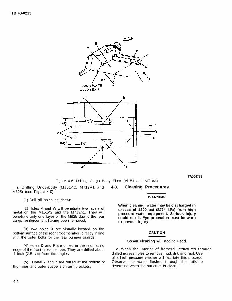
TB 43-0213
i. Drilling Underbody (M151A2, M718A1 andM825) (see Figure 4-9).
(1) Drill all holes as shown.
(2) Holes V and W will penetrate two layers ofmetal on the M151A2 and the M718A1. They willpenetrate only one layer on the M825 due to the rearcargo reinforcement having been removed.
(3) Two holes X are visually located on thebottom surface of the rear crossmember, directly in linewith the outer bolts for the rear bumper guards.
(4) Holes D and F are drilled in the rear facingedge of the front crossmember. They are drilled about1 inch (2.5 cm) from the angles.
TA504779Figure 4-6. Drilling Cargo Body Floor (Vl151 and M718A).
(5)the inner
4-4
Holes Y and Z are drilled at the bottom ofand outer suspension arm brackets.
4-3. Cleaning Procedures.
WARNING
When cleaning, water may be discharged inexcess of 1200 psi (8274 kPa) from highpressure water equipment. Serious injurycould result. Eye protection must be wornto prevent injury.
CAUTION
Steam cleaning will not be used.
a. Wash the interior of framerail structures through drilled access holes to remove mud, dirt, and rust. Useof a high pressure washer will facilitate this process.Observe the water flushed through the rails todetermine when the structure is clean.

TB 43-0213
b. Allow at least four hours for vehicle drying. c. Prime and paint those areas showing bare metal.Additional drying time may be required if unfavorable Allow painted areas time to dry before rustproofing.weather conditions exist. Compressed air may be usedto speed up the drying process.
TA504780Figure 4-7. Drilling Cargo Body Floor (M825 Only).
4-5
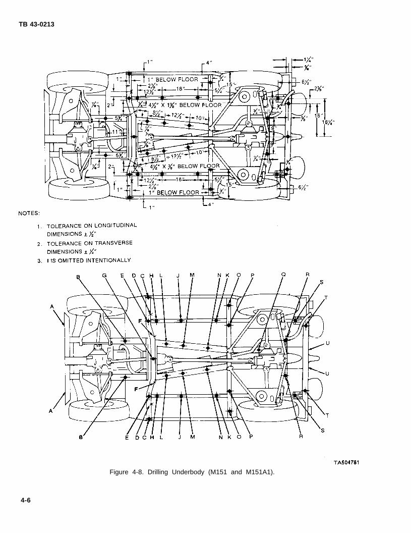
TB 43-0213
Figure 4-8. Drilling Underbody (M151 and M151A1).
4-6

TB 43-0213
Figure 4-9. Drilling Underbody (M151A2, M718A1, and M825),TA504782
4-7

TB 43-0213
Section Ill. RUSTPROOFING
4-4. Rustproofing Procedures.
CAUTION
Do not spray any portion of moving compo-nents, transmission, transfer case, cylin-ders, pumps, valves, prop shaft, exhaustsystem, rubber bump stops, brakedrums,brake backing plates, parking brake linkage,shift linkage, tires, electrical components,engine linkages, or air intake systems. Cov-er all areas with paper where necessary.
●
●
a.
NOTE
There are areas where a 10 mil wet filmthickness cannot be obtained withoutwasting a large amount of compound. Inthose areas, complete coverage of thesurface area is necessary at whateverthickness is obtainable.
For rustproofing procedures of specificbody items, refer to Figure 4-10 throughFigure 4-15.
Dry Film Thickness Requirements, A five mil dryfilm thickness is required for adequate rustproofingprotection. A 10 mil wet film thickness is required toobtain a minimum five mil dry film thickness. Ifneeded, the vehicle can be resprayed to reach properthickness.
b. Spraying Pressure. The rustproofing compoundshould be applied to sheet metal and structuralmembers in even coats. Spraying pressure should be aslow as possible while maintaining an even spray pattern.An acceptable starting point is 40 psi (276 kPa), butadjustments may have to be made, due to temperaturechanges and differences in rustproofing compound.Using too much pressure will waste compound bycausing overspray and excessively thick coatings.
c. Rustproofing Firewall (see Figure 4-10).
(1) Insert flexible tool as far as possible intofirewall holes A and B, then spray in all directions whileslowly withdrawing tool. Enlarge holes to allow entranceof flexible tool, if necessary.
(2) Plug all holes.
PROCEDURES
TA504783Figure 4-10. Rustproofing Firewall.
d. Rustproofing Crew Compartment Rails (seeFigure 4-11).
(1)the innerdirections
(2)
(3)
Insert 90 degree short tool into hole A ofrails as far as possible, then spray in all
Plug all holes.
Use short rigid tool to sprav the floor areasunder the gas tank and all areas including thesurrounding sills.
TA504784Figure 4-11. Rustproofing Crew
Compartment Rails.
e. Rustproofing Spare Tire Carrier (seeFigure 4-4), Insert 90 degree short tool into holes A,B, and C of the spare tire carrier, then spray in alldirections.
4-8

TB 43-0213
f. RustproofingFigure 4-12).
Windshield Frame (see
NOTE
C are used on the M825
(3) Plug all holes.
g. Rustproofing Cargo Body (see Figure 4-13).
(1) Insert 90 degree short tool into holes A,B,C, and D of the cargo bed and spray in all directions.
Only holes B andSeries.
(2) Use the short rigid tool to sprayall surfaces. -of the taillight openings. -
(3) (M825 only). Insert 90 degree short tool in
(1) Insert flexible tool into hole A of the upperframe and hole B of the side frame, then spray slowlywhile withdrawing the tool.
(2) Insert 90 degree short tool into holes C ofthe lower frame and spray in all directions.
holes A and B and spray
(4) Plug all holes.
in all directions.
TA504785Figure 4-12. Rustproofing Windshield Frame.
TA504786
4-9
Figure 4-13. Rustproofing Cargo Body.
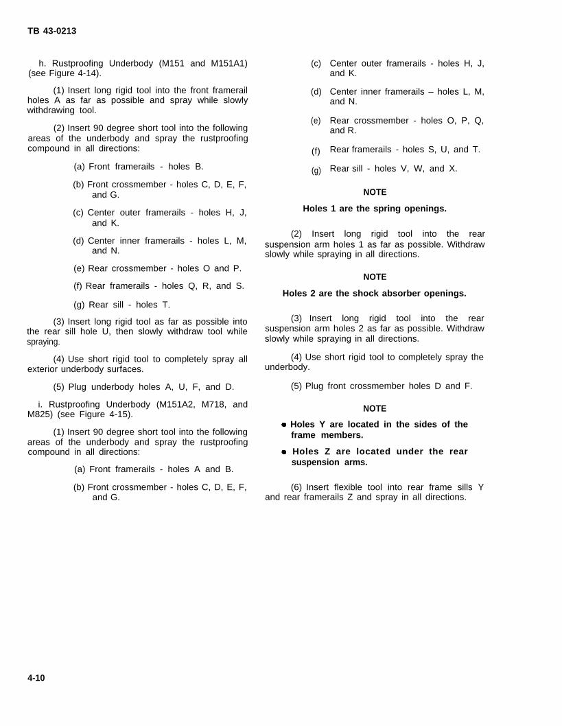
TB 43-0213
h. Rustproofing Underbody (M151 and M151A1)(see Figure 4-14).
(1) Insert long rigid tool into the front framerailholes A as far as possible and spray while slowlywithdrawing tool.
(2) Insert 90 degree short tool into the followingareas of the underbody and spray the rustproofingcompound in all directions:
(a) Front framerails - holes B.
(b) Front crossmember - holes C, D, E, F,and G.
(c) Center outer framerails - holes H, J,and K.
(d) Center inner framerails - holes L, M,and N.
(e) Rear crossmember - holes O and P.
(f) Rear framerails - holes Q, R, and S.
(g) Rear sill - holes T.
(3) Insert long rigid tool as far as possible intothe rear sill hole U, then slowly withdraw tool whilespraying.
(4) Use short rigid tool to completely spray allexterior underbody surfaces.
(5) Plug underbody holes A, U, F, and D.
i. Rustproofing Underbody (M151A2, M718, andM825) (see Figure 4-15).
(1) Insert 90 degree short tool into the followingareas of the underbody and spray the rustproofingcompound in all directions:
(a) Front framerails - holes A and B.
(b) Front crossmember - holes C, D, E, F,and G.
(c)
(d)
(e)
(f)
(g)
Center outer framerails - holes H, J,and K.
Center inner framerails – holes L, M,and N.
Rear crossmember - holes O, P, Q,and R.
Rear framerails - holes S, U, and T.
Rear sill - holes V, W, and X.
NOTE
Holes 1 are the spring openings.
(2) Insert long rigid tool into the rearsuspension arm holes 1 as far as possible. Withdrawslowly while spraying in all directions.
NOTE
Holes 2 are the shock absorber openings.
(3) Insert long rigid tool into the rearsuspension arm holes 2 as far as possible. Withdrawslowly while spraying in all directions.
(4) Use short rigid tool to completely spray theunderbody.
(5) Plug front crossmember holes D and F.
NOTE
Holes Y are located in the sides of theframe members.
Holes Z are located under the rearsuspension arms.
(6) Insert flexible tool into rear frame sills Yand rear framerails Z and spray in all directions.
4-10

TB 43-0213
TA504787Figure 4-14. Rustproofing Underbody (M151 and M151Al1.
4-11

TB 43-0213
Figure 4-15. Rustproofing Underbody (M151A2, M718A, and M825).TA504788
4-12

4-5. Rustproofing Inspection.
a. Check the vehicle to ensure that all areasrequiring rustproofing compound have been properlyand completely coated.
(1) Check seams, welds, corners, and boxedareas to ensure that they are adequately coated.
(2) Check wet film thickness with a wet filmthickness gage (see Figure 4-16). A wet film thicknessof 10 mils is required. In areas where a wet filmthickness of 10 mils cannot be obtained or wherethickness cannot be measured, inspect for complete-ness of coverage.
(3) Check all drain holes to ensure that they areopen.
(4) Check all inspection holes and drilledaccess holes to ensure that compound coverage isadequate. Use of a high intensity inspection light willhelp with this process.
(5) Check vehicle to ensure that no compoundhas been applied to prohibited areas (see CAUTION,paragraph 4-4).
NOTE
Plugging of access holes may be delayeduntil after vehicle inspection, if inspectionoccurs immediately after rustproofing. If
inspection is delayedcompound may drip
b. Plug access holes.
TB 43-0213
too long, rustproofingfrom access holes.
TA504789Figure 4-16. Film Thickness Gage,
4-6. Component Installation.
Install all components that were removed inparagraph 4-1 of this chapter (see TM 9-2320-218-20and TM 9-2320-218-34).
4-13/(4-14 Blank)

TB 43-0213
CHAPTER 51 1/4-TON TRUCK: M880 AND M890 SERIES
Section 1. PRELIMINARY PROCEDURES
5-1. Component Removal.
CAUTION
Electric leads to light assemblies do nothave to be disconnected. Tape the light as-sembly to body or cab to prevent damage.
NOTE
On cargo trucks with body mountingequipment (troop seats, cargo cover, S-250shelter, radio rack, etc) remove equipmentas required to allow for access to rustproof-ing points.
a. Prior to rustproofing, the following componentsmust be removed for access (see TM 9-2320-266-20and TM 9-2320-266-34):
(1)
(2)
(3)
(4)
(5)
Seat assembly.
Floormat (discard).
Domelight assembly.
Both sunvisors.
Vent covers and control (left side),
(6) Both
(7) Both
(8) Both
(9) Both
(10) Both
taillight assemblies.
headlight assemblies.
front parking light assemblies.
front side marker lights.
door window regulator handles, door. .handles, black plastic door trim liner, and clear plasticsheet from door.
(11)
(12)
(13)
(14)
(15)
(16)
(17)
Rubber plugs
Rubber plugs
Rubber plugs
Rubber plugs
inside rocker panels.
in floor board.
behind seat,
in kick panels.
Spare tire and mounting bracket.
Both doorjamb scuff plates.
Remove both batteries for 24 volt system (ifso equipped).
b. Figure 5-1 provides a reference illustration of theM880 and M890 1 1/4-Ton Trucks discussed in thischapter.
Figure 5-1. M880 and M890 1 1/4-Ton Trucks.TA504790
5-1

TB 43-0213
Section Il. DRILLING AND CLEANING PROCEDURES
5-2. Drilling Procedures.
NOTE
Unless otherwise indicated, all holesdrilled should be sight drilled and shouldbe 1/2 inch (1.3 cm) in diameter.
Drill holes at approximate locations indi-cated by the black dots.
a. General. Refer to paragraph 3-15 for generaldrilling instructions.
b. Drilling Inner Hood Panel (see Figure 5-2). Onolder models, drill 19 holes in the inner hood panelsupport. Later models will have existing holes which arelocated at points D, K, L, and R.
c. Drilling Cowl (see Figure 5-3), Drill 11 holes incowl. Holes A and B should be 5 inches (12.7 cm)from the inside of fenders. Hole F should be 6 inches(15.2 cm) from the inside of the fender. All other holesare sight drilled.
TA504791Figure 5-2. Drilling Inner Hood Panel.
TA504792
Figure 5-3. Drilling Cowl.
5-2

TB 43-0213
d. Drilling Front Fenders and Rocker Panels (seeFigure 5-4). Drill four holes on each side. Holes A andB may be sight drilled. Hole C is drilled below thecenter of the fender support. Hole D can be sightdrilled inside the fender well.
Figure 5-4. Drilling Front FendersRocker Panels.
TA504793and
e. Drilling Taillight Opening (see Figure 5-5). Drillone hole A in each taillight opening. Holes are sightdrilled.
TA504794Figure 5-5. Drilling Taillight Opening.
f. Drilling Front Cargo Bed (see Figure 5-6). Drillfive holes in front of the cargo bed, Hole C is drilledfirst at the center of the bed. The remaining four holesare then spaced approximately 12 inches (30.5 cm)apart.
TA504795Figure 5-6. Drilling Front Cargo Bed.
g. Drilling Rear of Doors (see Figure 5-7). Drilltwo holes A and B in each door. Holes are sight drilled.
TA504796Figure 5-7. Drilling Rear of Doors.
5-3

TB 43-0213
h. Drilling Top of Doors (see Figure 5-8). Drill j. Drilling Lower Front Doorjambs (seefour holes A, B, C, and D in the top of each door. Figure 5-10). Drill one hole A in the lower front areaHoles are sight drilled. of each doorjamb. The hole is to be sight drilled.
TA504797Figure 5-8. Drilling Top of Doors. TA504799
i. Drilling Front of Doors (see Figure 5-9). DrillFigure 5-10. Drilling Lower
four holes A, B, C, and D in the front of each door.Front Doorjambs.
Holes are to be sight drilled with holes A and B k. Drilling Roof and Top of Doorjambs (seeapproximately 10 inches (25.4 cm) apart. Figure 5-11).
(1) Drill a total of 12 holes in the roof and thetop of doorjambs on both sides.
(2) Holes A are drilled 3 1/4 inches (8.3 cm) tothe rear of metal joint. Holes B are drilled 2 inches(5.1 cm) forward of metal joint. Holes C and D aredrilled at 6-inch (15.2 cm) intervals forward of hole B.
(3) Holes E and H are drilled directly in linewith headlined side creases and 1 3/4 inches (4.4 cm)from the front headlined crease.
(4) Holes F and G are drilled at approximately13-inch (33 cm) intervals from holes E and H, and1 3/4 inches (4.4 cm) from the front headlined crease.
TA504798Figure 5-9. Drilling Front of Doors.
5-4

TB 43-0213
Figure 5-11. Drilling Roof and Top of Doorjambs.
1. Drilling Rear Window Frame (see Figure 5-12).Drill five holes A, B, C, D, and E in rear window frame.Hole C is centered on the window frame. Holes A, B,D, and E are drilled at 12-inch (30.5 cm) intervals onboth sides of hole C.
TA504801Figure 5-12. Drilling Rear Window Frame.
m. Drilling Body Support Channels (seeFigure 5-13), Drill four holes A, B, C, and D in bodysupport channels. Holes are to be sight drilled.
TA504802Figure 5-13, Drilling Body
Support Channels.
5-5

TB 43-0213
5-3. Cleaning Procedures. a. Wash interior of frame rail structures throughdrilled access holes to remove mud, dirt, and rust. Use
WARNINGof a high pressure washer will facilitate this process.Observe the water flushed through the rails todetermine when the structure is clean.
When cleaning, water may be discharged inexcess of 1200 psi (8274 kPa) from highpressure water equipment. Serious injurycould result. Eye protection must be wornto prevent injury.
b. Allow at least four hours for vehicle drying.Additional drying time may be required if unfavorableweather conditions exist. Compressed air may be used
CAUTION
Steam cleaning will not
to speed up the drying process.
c. Prime and paint those areas showing bare metal.Use inspection light where available. Allow painted
be used. areas time to dry before rustproofing.
Section Ill. RUSTPROOFING PROCEDURES
5-4. Rustproofing Procedures. a. Dry Film Thickness Requirements. A five mil dry
CAUTION
Do not spray any portion of movingcomponents, transmission, transfer case,cylinders, pumps, valves, prop shaft,exhaust system, rubber bump stops, brake-drums, brake backing plates, parking brakelinkage, shift linkage, tires, electricalcomponents, engine linkages, or air intakesystems. Cover all areas with paper wherenecessary.
NOTE
There are areas where a 10 mil wet filmthickness cannot be obtained withoutwasting a large amount of compound. Inthose areas, complete coverage of thesurface area is necessary at whateverthickness is obtainable.
For rustproofing procedures of specificbody items, refer to Figure 5-14 through5-29.
film thickness is required for adequate rustproofingprotection. A 10 mil wet film thickness is required toobtain a minimum five mil dry film thickness. Ifneeded, the vehicle can be resprayed to reach properthickness.
b. Spraying Pressure. The rustproofing compoundshould be applied to sheet metal and structuralmembers in even coats. Spraying pressure should be aslow as possible while maintaining an even spray pattern.An acceptable starting point is 40 psi (276 kPa), butadjustments may have to be made due to temperaturechanges and differences in rustproofing compound.Using too much pressure will waste compound bycausing overspray and excessively thick coatings.
c. Rustproofing Underbody (see Figure 5-14).
(1) Insert 90 degree short tool into bodysupport channel holes A, B, C, and D and spray in alldirections.
(2) Insert 90 degree flexible tool in cargo bedchannels as far as possible, then withdraw tool slowlywhile spraying.
5-6

TB 43-0213
(3) Use short rigid tool toareas of the complete underbody.
TA504803Figure 5-14. Rustproofing Underbody.
spray all accessible e. Rustproofing Rocker Panels (see Figure 5-16).
(4) Spray all inaccessible areas with a 90 degreeshort cone: framerails, bedside walls, wheel lips, andwheelwells.
d. Rustproofing Cargo Body Walls (seeFigure 5-1 5). Insert 90 degree tool through openings inthe inner cargo walls at areas A and B. Spray in alldirections.
TA504804Figure 5-15. Rustproofing Cargo
Body Walls.
NOTE
Holes A, B, and C are located under thebottom edge of the vehicle.
(1) Insert 90 degree short tool in rocker panelholes A, B, C, and fender bottom well holes D.
TA504805Figure 5-16. Rustproofing Rocker Panels
5-7

TB 43-0213
(2) Spray in all directions.
(3) Plug holes D in fender bottom well.
f. Rustproofing Cowl (see Figure 5-17).
(1) Insert 90 degree tool into holes A through Lin cowl and spray in all directions.
(2) Completely cover open seam M using shortrigid tool; also coat cowl.
(3) Spray directly over holes A through L tocover areas that may have been missed by the 90 degreeshort tool.
g. Rustproofing Engine Compartment (seeFigure 5-18).
(1) Use short rigid 90 degree tool to completelycoat the following parts of the engine compartment:
(a) Front of cab wall.
(b) Rear of radiator wall.
(c) Wheelwell top.
(d) Inside of fender.
(e) Bottom of front fender.
(f) Bottom of rear fender.
TA504806
Figure 5-17. Rustproofing Cowl.
TA504807
Figure 5-18. Rustproofing Engine Compartment.
5-8

TB 43-0213
(2) Ensure that all seams, welds and corners are i. Rustproofing Grille (see Figure 5-20). U s ecoated with rustproofing compound. Rustproof both 90 degree short tool to coat rear of grille, front ofsides of the engine compartment. Remove battery and radiator wall, and rear of headlamp bezels.rustproof battery tray of 24 volt system (if applicable).Cover all areas that are inaccessible with short rigid 90degree tool.
h. Rustproofing Hood (see Figure 5-19).
(1) Insert 90 degree short tool into holes C, D,E, F, G, H, J, L, O, P, Q, and R and spray in alldirections.
(2) Insert flexible tool as far as possible intoholes A, B, T, S, N, M, U, and V, then withdraw toolslowly while spraying.
(3) Use short rigid tool to completely coat innerpanel and spray over all holes to cover areas that may TA504809have been missed by the 90 degree short tool. Figure 5-20. Rustproofing Grille.
TA504808Figure 5-19. Rustproofing Hood.
5-9
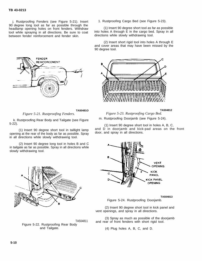
TB 43-0213
j. Rustproofing Fenders (see Figure 5-21). Insert 1. Rustproofing Cargo Bed (see Figure 5-23).90 degree long tool as far as possible through theheadlamp opening holes on front fenders. Withdraw (1) Insert 90 degree short tool as far as possibletool while spraying in all directions. Be sure to coat into holes A through E in the cargo bed. Spray in allbetween fender reinforcement and fender skin. directions while slowly withdrawing tool.
(2) Insert short rigid tool into holes A through Eand cover areas that may have been missed by the90 degree tool.
TA50481O TA504812
Figure 5-21. Rustproofing Fenders. Figure 5-23. Rustproofing Cargo Bed.
k. Rustproofing Rear Body and Tailgate (see Figure m. Rustproofing Doorjamb (see Figure 5-24).
5-22). (1) Insert 90 degree short tool in holes A, B, C,
(1) Insert 90 degree short tool in taillight lamp and D in doorjamb and kick-pad areas on the front
opening at the rear of the body as far as possible. Spray door, and spray in all directions.
in all directions while slowly withdrawing tool.
(2) Insert 90 degree long tool in holes B and Cin tailgate as far as possible. Spray in all directions whileslowly withdrawing tool.
TA504813Figure 5-24. Rustproofing Doorjamb.
(2) Insert 90 degree short tool in kick panel andvent openings, and spray in all directions.
(3) Spray as much as possible of the doorjambTA504811
Figure 5-22. Rustproofing Rear Bodyand rear of front fenders with short rigid tool.
and Tailgate. (4) Plug holes A, B, C, and D.
5-10

TB 43-0213
n. Rustproofing Front Floor (see Figure 5-25).Insert 90 degree short tool in hole A on front floor andspray in all directions.
0, Rustproofing Rocker Panels and Rear Floor (seeFigure 5-26).
(2) Insert 90 degree short tool in holes A and Bon the rear floor and spray in all directions.
(3) Plug hole C.
p. Rustproofing Roof and Doorjamb Tops (seeFigure 5-27).
(1) Insert 90 degree short tool in top ofdoorjamb holes A, B, C, and D and in holes E, F, G,and H in roof, and spray in all directions.
(2) Insert 90 degree short tool in sunvisoraccess hole as far as possible and spray in all directionswhile slowly withdrawing tool.
TA504814Figure 5-25. Rustproofing Front Floor.
(1) Insert 90 degree short tool into hole C in therocker panel as far as possible, then spray in alldirections while slowly withdrawing tool.
TA504815Figure 5-26. Rustproofing Rocker Panels
and Rear Floor.
Figure 5-27. RustproofingDoorjamb Tops.
(3) Insert flexible tool as far
TA604816Roof and
as possible into thedomelight access hole in the roof aid spray in alldirections while slowly withdrawing tool. Do this steptwice, once to the left and once to the right.
(4) Insert short rigid tool into all openings andholes A through H and spray all areas not covered bythe 90 degree tool.
(5) Plug holes A through H.
q. Rustproofing Rear Window Frame (see Fig-ure 5-28).
(1) Insert 90 degree short tool in rear windowframe holes A, B, C, D, and E as far as possible, thenspray in all directions while slowly withdrawing tool.
(2) Insert flexible tool in rear window frameholes F as far across as possible, then spray in alldirections while slowly withdrawing tool.
(3) Plug holes A through E.
5-11
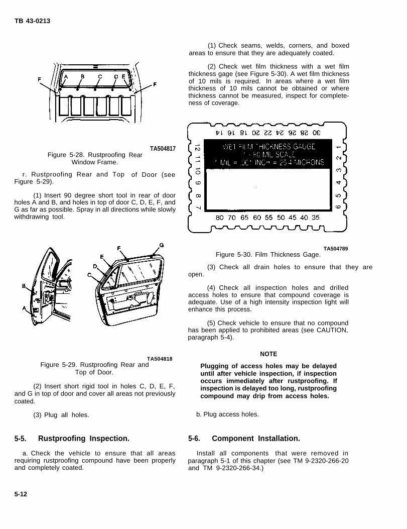
TB 43-0213
Figure 5-28. RustproofingWindow Frame.
r. Rustproofing Rear and TopFigure 5-29).
TA504817Rear
of Door (see
(1) Insert 90 degree short tool in rear of doorholes A and B, and holes in top of door C, D, E, F, andG as far as possible. Spray in all directions while slowlywithdrawing tool.
TA504818Figure 5-29. Rustproofing Rear and
Top of Door.
(2) Insert short rigid tool in holes C, D, E, F,and G in top of door and cover all areas not previouslycoated.
(3) Plug all holes.
5-5. Rustproofing Inspection.
a. Check the vehicle to ensure that all areasrequiring rustproofing compound have been properlyand completely coated.
5-12
(1) Check seams, welds, corners, and boxedareas to ensure that they are adequately coated.
(2) Check wet film thickness with a wet filmthickness gage (see Figure 5-30). A wet film thicknessof 10 mils is required. In areas where a wet filmthickness of 10 mils cannot be obtained or wherethickness cannot be measured, inspect for complete-ness of coverage.
TA504789Figure 5-30. Film Thickness Gage.
(3) Check all drain holes to ensure that they are open.
(4) Check all inspection holes and drilledaccess holes to ensure that compound coverage isadequate. Use of a high intensity inspection light willenhance this process.
(5) Check vehicle to ensure that no compoundhas been applied to prohibited areas (see CAUTION,paragraph 5-4).
NOTE
Plugging of access holes may be delayeduntil after vehicle inspection, if inspectionoccurs immediately after rustproofing. Ifinspection is delayed too long, rustproofingcompound may drip from access holes.
b. Plug access holes.
5-6. Component Installation.
Install all components that were removed inparagraph 5-1 of this chapter (see TM 9-2320-266-20and TM 9-2320-266-34.)

TB 43-0213
CHAPTER 63/4-TON AND 1 1/4-TON TRUCK: M1008, M1008A1,
M1009, M1010, M1028, AND M1031
Section I. PRELIMINARY PROCEDURES
6-1. Component Removal.
CAUTION
Electrical leads to light assemblies do nothave to be disconnected. Tape the light as-sembly to body or cab to prevent damage.
NOTE
On cargo trucks with body mounting equip-ment or kits (troop seats, cargo covers,etc. ) remove equipment as required to al-Iow for access to rustproofing points.
a. Prior to rustproofing, place all windows in closedposition. The following components must be removedfor access (see TM 9-2320-289-20 and TM 9-2320-289-34) :
(1) Vent covers and controls (both sides).
(2) Spare tire and mounting bracket (all exceptM1009).
(3) Fuel tank shield (all except M1009).
(4) Lower front fender mudguards left andright.
(5) Both sunvisors.
(6) Floormat.
(a) After removing floormat, discard pad-ding and apply nonslip flight deck com-pound (NSN 5610-00-782-5556 l-gal.kit).
(b) Install rubber mat without padding.
(7) Both taillight assemblies.
(8) Rubber plugs in doors. Remove and retain1-inch (2.5 cm) plug.
(9) Rubber plugs in doorjamb. Remove anddiscard 1/2-inch (1.3 cm) plug.
(10) Remove tailgate glass cover (M 1009 only).
b. All 3/4- and 1 1/4-Ton Trucks discussed in thischapter are illustrated in Figure 6-1.
TA504819Figure 6-1. M1008, M1008A1, M1009, M1010, MI028, and M1031 Series Trucks.
6-1

TB 43-0213
Section Il. DRILLING AND CLEANING PROCEDURES
6-2. Drilling Procedures.
NOTE
Unless otherwise indicated, all holes shouldbe sight drilled and should be 1/2 inch(1.3 cm) in diameter,
a. General. Refer to paragraph 3-15 for generaldrilling instructions.
b. Drilling TopFigure 6-2). Enlarge(1.3 cm).
Radiator Core Support (seeexisting holes A and B to 1/2 inch
TA504821Figure 6-3. Drilling Tailgate.
TA504820Figure 6-2. Drilling Top Radiator Core
Support (M1008).
c. Drilling Tailgate. (Model M1008) (seeFigure 6-3). Enlarge existing holes A, B, C, and D to1/2 inch (1.3 cm).
d. Drilling Front of Cargo Bed (see Figure 6-4).Drill two holes A and B in front of cargo bed. Holes areto be drilled 12 inches (30.5 cm) in from side of cargobed.
TA504822Figure 6-4. Drilling Front of Cargo Bed.
6-2

TB 43-0213
e. Dri l l ing Rear of Doors (Typical) (see g. Drilling Rocker Panels (Typical) (seeFigure 6-5). Drill one hole A in each door 4 inches Figure 6-7). Drill one hole A in rocker panels.(10.2 cm) above top of door trim. Existing hole B canbe used for lower door area.
TA504823Figure 6-5. Drilling Rear of
Doors (Typical).
f. Dril l ing Front Lower Door and Doorjamb(Typical) (see Figure 6-6). Enlarge existing holes A indoorjamb to 1/2 inch (1.3 cm). Holes B are to be sightdrilled at bottom front of doors.
TA504825Figure 6-7. Drilling Rocker
Panels (Typical),
NOTE
In Figure 6-8, holes E, F, G, H, and I do notapply to the Ml 009.
h. Drilling Body Support Channels (seeFigure 6-8). Drill two holes A and B. Holes C, D, E, F,G, H, and I are existing holes which must be enlarged to1/2 inch (1.3 cm). All other access holes are largeenough to receive tools.
i. Drilling Top of Doorjamb (see Figure 6-9), Drilla total of four holes in the top of both doorjambs.
(1) Drill holes A 12 inches (30.5 cm) from topof doorjamb openings.
(2) Drill holes B 16 inches (40.6 cm) from holesA. Holes A and B cover all models.
(3) Model M 1009holes. Drill hole C evendoorjambs. Drill holes Dfrom seatbelt bolt.
only. Drill a total of fourwith rubber bumper, bothand E 9 inches (22.9 cm)
TA504824Figure 6-6. Drilling Front Lower Door and
Doorjamb (Typical).
6-3

TB 43-0213
TA504826Figure 6-8. Drilling Body Support Channels.
6-3. Cleaning Procedures.
WARNING
When cleaning, do not discharge water inexcess of 600 psi (4137 kPa) from highpressure equipment. Serious injury couldresult. Eye protection must be worn toprevent injury.
CAUTION
Steam cleaning will not be used.
a. Wash the interior of frame rail structures throughdrilled access holes to remove mud, dirt, etc. Use ofhigh pressure washer will facilitate this process. Observewater flushed through the rails to determine when thestructure is clean.
b. Allow at least four hours for vehicle drying.Additional drying time may be required if unfavorableweather conditions exist. Compressed air may be usedto speed up the drying process.
TA504827c. Prime and paint those areas showing bare metal.. .
Figure 6-9. Drilling Top of Doorjamb. Allow painted areas time to dry before rustproofing.
6-4

TB 43-0213
Section Ill. RUSTPROOFING PROCEDURES
6-4. Rustproofing Procedures.
CAUTION
Do not spray any portion of moving compo-nents, transmission, transfer case, cylin-ders, pumps, valves, prop shaft, exhaustsystem, rubber bump stops, brakedrums,backing plates, parking brake linkage, en-gine linkage, or air intake systems. Cover allareas with paper where necessary.
●
●
a.
NOTE
There are areas where a 10 mil wet filmthickness cannot be attained withoutwasting a large amount of compound. Inthose areas, complete coverage of thesurface area is necessary at whateverthickness is obtainable.
For rustproofing procedures of specificbody items refer to Figure 6-10 throughFigure 6-27.
Dry Film Thickness Requirements. A five mil dryfilm thickness isprotection. A 10
required for adequate rustproofingmil wet film thickness is required to
obtain minimum five mil dry film thickness. If needed,the vehicle can be resprayed to reach proper thickness.
b. Spraying Pressure. The rustproofing compoundshould be applied to sheet metal structural members ineven coats. An acceptable starting point to maintain aneven spray pattern, is 40 psi (276 kPa), but adjustmentsmay have to be made due to temperature changes anddifferences in rustproofing compound.
c. Rustproofing Underbody (M1008 Series) (seeFigure 6-10).
(1) Insert flexible tool as far as possible into theends of the body support channels A through F, andcargo bed channels G through R. Slowly withdraw toolwhile spraying.
(2) Use short rigid tool to complete spraying ofall accessible areas of the underbody.
(3) Use 90 degree short tool to spray all thoseareas that were inaccessible with the cone spray tool,such as framerails, bed side walls, and wheel lips andwells.
(4) Use short rigid tool to spray the bottom sideof the fuel tank and both sides of the fuel tank shield.Also spray allunderside.
accessible areas of the radiator cowling
Figure 6-10. Rustproofing
d. Rustproofing Underbody (M1009) (seeFigure 6-1 1).
(1) Insert flexible tool as far as possible into theends of body support channels A through F and all
Underbody (M1008 Series).
existing holes in the cargowithdraw tool while spraying.
TA504828
bed channels. Slowly
(2) Use short rigid tool to spray all accessibleareas of the underbody.
6-5

TB 43-0213
Figure 6-11. Rustproofing
(3) Use 90 degree short tool to spray all thoseareas that were inaccessible with the cone spray tool,such as framerails, bed rails, side walls, and wheel lipsand wells.
(4) Use 90 degree short tool to spray the bottomside of the fuel tank and both sides of the fuel tankshield.
e. Rustproofing Cargo Body Walls (seeFigure 6-12).
(1) Insert 90 degreein inner walls and spray in
long tool through openingsall directions in area A.
Figure
(2) Inserttaillight openings
TA5048306-12. Rustproofing Cargo
Body Walls.
90 degree long tool into hole inand spray in all directions in area B.
TA504829Underbody (M1009).
f. Rustproofing Cowl (see Figure 6-13).
(1) Insert flexible tool into the open seam ofchannel A of the cowl and spray in all directions.
(2) Use 90 degree short tool to completely sprayareas missed by the flexible tool.
TA504831Figure 6-13. Rustproofing Cowl.
g. Rustproofing Between Cab and Cargo Body(M1008, M1008A1, and M1028) (see Figure 6-14). Insert long rigid tool between the bed and cab area A,and spray in all directions.
6-6

TB 43-0213
TA504832Figure 6-14. Rustproofing Between Cab
and Cargo Body (M1008, M1008AI,and M1028).
h. Rustproofing Engine Compartment (seeFigure 6-15),
(1) Usefollowing areas
(a)
(b)
(c)
short rigid tool to completely spray theof the engine compartment:
Front of cab firewall.
Rear of the radiator wall.
The inside, bottom front, and bottomrear of the fender.
NOTE
Ensure that all seams, welds and corners ofthe engine compartment are covered.
(2) Use flexible tool to spray all areasinaccessible with the short rigid tool.
TA504833Figure 6-15. Rustproofing
Engine Compartment.
i. Rustproofing Hood (see Figure 6-16).
(1) Insert flexible tool into the hood boxchannel A and B as far as possible, then slowlywithdraw tool while spraying.
(2) Use short rigid tool to completely spray theinner panel of the hood.
(3) Use 90 degree short tool to spray in allexisting holes of the inner hood and all areas missed bythe flexible tool.
Figure 6-16. Rustproofing Hood.TA504834
6-7
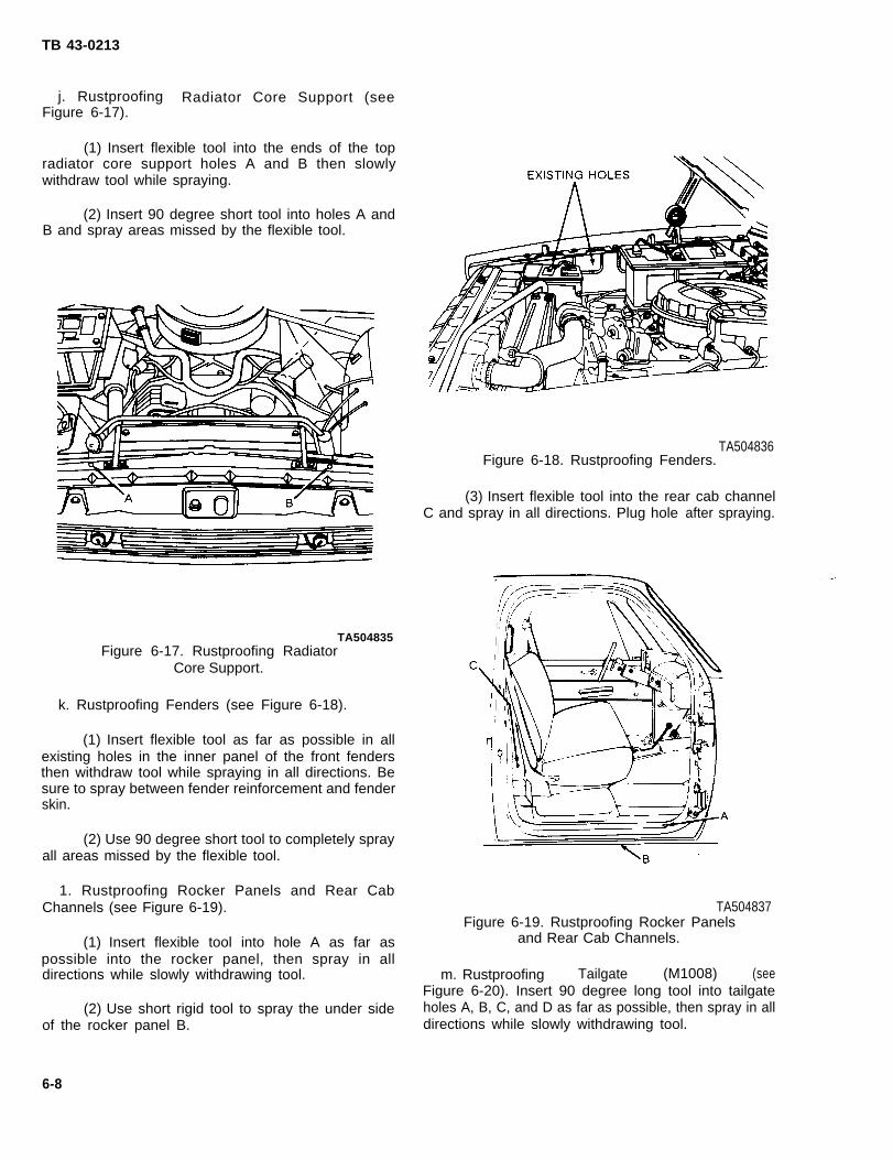
TB 43-0213
j. Rustproofing Radiator Core Support (seeFigure 6-17).
(1) Insert flexible tool into the ends of the topradiator core support holes A and B then slowlywithdraw tool while spraying.
(2) Insert 90 degree short tool into holes A andB and spray areas missed by the flexible tool.
TA504835Figure 6-17. Rustproofing Radiator
Core Support.
k. Rustproofing Fenders (see Figure 6-18).
(1) Insert flexible tool as far as possible in allexisting holes in the inner panel of the front fendersthen withdraw tool while spraying in all directions. Besure to spray between fender reinforcement and fenderskin.
(2) Use 90 degree short tool to completely sprayall areas missed by the flexible tool.
1. Rustproofing Rocker Panels and Rear CabChannels (see Figure 6-19).
(1) Insert flexible tool into hole A as far aspossible into the rocker panel, then spray in alldirections while slowly withdrawing tool.
(2) Use short rigid tool to spray the under sideof the rocker panel B.
TA504836Figure 6-18. Rustproofing Fenders.
(3) Insert flexible tool into the rear cab channelC and spray in all directions. Plug hole after spraying.
TA504837Figure 6-19. Rustproofing Rocker Panels
and Rear Cab Channels.
m. Rustproofing Tailgate (M1008) (seeFigure 6-20). Insert 90 degree long tool into tailgateholes A, B, C, and D as far as possible, then spray in alldirections while slowly withdrawing tool.
6-8

TB 43-0213
TA504838Figure 6-20. Rustproofing
Tailgate (M1008).
n. Rustproofing Cargo Bed (M1008) (seeFigure 6-21).
(1) Insert flexible tool into holes A and B of thefront top cargo bed as far as possible, then spray in alldirections while withdrawing tool.
(2) Insert short rigid tool into holes C through Hand spray in all directions while slowly withdrawing tool.
o. Rustproofing Cargo Body (M1009) (seeFigure 6-22). Insert 90 degree short tool into holes Aand B as far as possible, then spray in all directionswhile slowly withdrawing tool.
TA504840Figure 6-22. Rustproofing Cargo
Body (M1009) .
p. Rustproofing Tailgate (M1009) (seeFigure 6-23).
NOTE
Place window in the full up position andsupport the glass.
(1) Insert 90 degree short tool into areas A ofthe inner tailgate panel and spray in all directions whileslowly withdrawing tool.
(2) Spray the inner side of the tailgate accesscover with the same tool.
q, Rustproofing Lower Doorjamb, Doors, and VentOpenings (see Figure 6-24).
(1) Insert flexible tool into hole A of the frontdoorjamb and spray in all directions.
(2) Insert 90 degree short tool into the ventopenings B and spray in all directions.
(3) Insert 90 degree short tool into hole C of thefront lower side of the door and spray door hinge side.
(4) Use 90 degree long tool to spray the vent
TA504839 window frame side while slowly withdrawing tool.
Figure 6-21. Rustproofing Cargo (5) Insert short rigid tool into holes A and B andBed (M1008). spray all areas missed by the 90 degree tool.
6-9
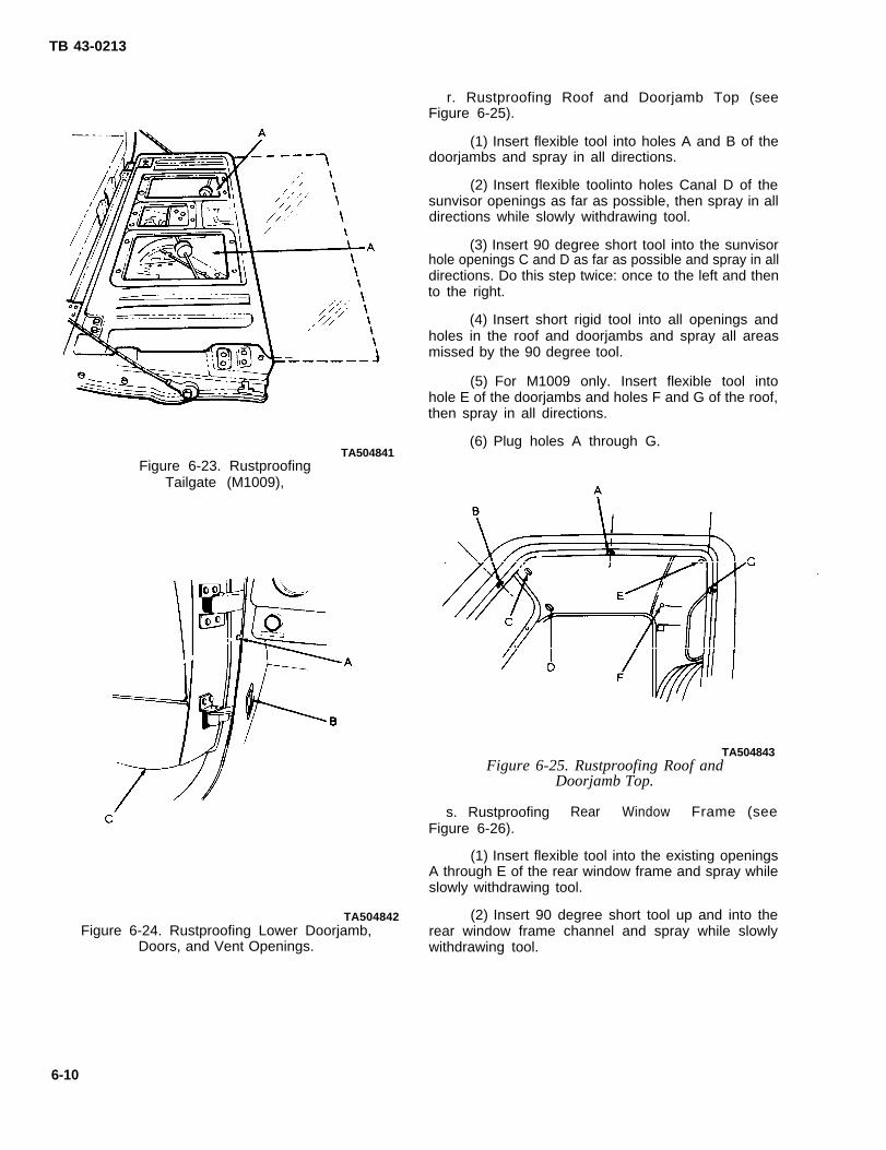
TB 43-0213
TA504841Figure 6-23. Rustproofing
Tailgate (M1009),
r. Rustproofing Roof and Doorjamb Top (seeFigure 6-25).
(1) Insert flexible tool into holes A and B of thedoorjambs and spray in all directions.
(2) Insert flexible toolinto holes Canal D of thesunvisor openings as far as possible, then spray in alldirections while slowly withdrawing tool.
(3) Insert 90 degree short tool into the sunvisorhole openings C and D as far as possible and spray in alldirections. Do this step twice: once to the left and thento the right.
(4) Insert short rigid tool into all openings andholes in the roof and doorjambs and spray all areasmissed by the 90 degree tool.
(5) For M1009 only. Insert flexible tool intohole E of the doorjambs and holes F and G of the roof,then spray in all directions.
(6) Plug holes A through G.
TA504843Figure 6-25. Rustproofing Roof and
Doorjamb Top.
TA504842Figure 6-24. Rustproofing Lower Doorjamb,
Doors, and Vent Openings.
s. Rustproofing Rear Window Frame (seeFigure 6-26).
(1) Insert flexible tool into the existing openingsA through E of the rear window frame and spray whileslowly withdrawing tool.
(2) Insert 90 degree short tool up and into therear window frame channel and spray while slowlywithdrawing tool.
6-10
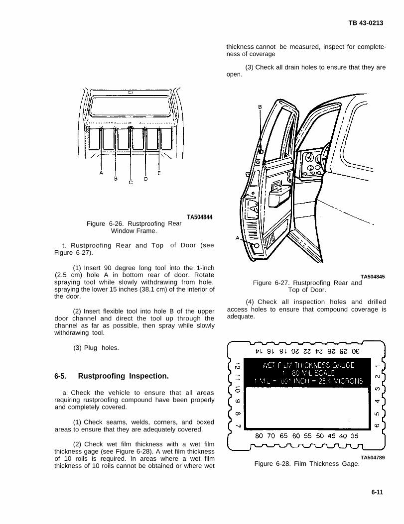
Figure 6-26. RustproofingWindow Frame.
t. Rustproofing Rear and TopFigure 6-27).
TA504844Rear
of Door (see
(1) Insert 90 degree long tool into the 1-inch(2.5 cm) hole A in bottom rear of door. Rotatespraying tool while slowly withdrawing from hole,spraying the lower 15 inches (38.1 cm) of the interior ofthe door.
(2) Insert flexible tool into hole B of the upperdoor channel and direct the tool up through thechannel as far as possible, then spray while slowlywithdrawing tool.
(3) Plug holes.
6-5. Rustproofing Inspection.
a. Check the vehicle to ensure that all areasrequiring rustproofing compound have been properlyand completely covered.
(1) Check seams, welds, corners, and boxedareas to ensure that they are adequately covered.
(2) Check wet film thickness with a wet filmthickness gage (see Figure 6-28). A wet film thicknessof 10 roils is required. In areas where a wet filmthickness of 10 roils cannot be obtained or where wet
thickness cannotness of coverage
TB 43-0213
be measured, inspect for complete-
(3) Check all drain holes to ensure that they areopen.
TA504845Figure 6-27. Rustproofing Rear and
Top of Door.
(4) Check all inspection holes and drilledaccess holes to ensure that compound coverage isadequate.
TA504789Figure 6-28. Film Thickness Gage.
6-11
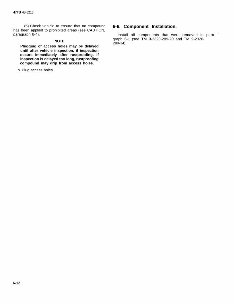
47TB 43-0213
(5) Check vehicle to ensure that no compound 6-6. Component Installation.has been applied to prohibited areas (see CAUTION,paragraph 6-4). Install all components that were removed in para- -
NOTE graph 6-1 (see TM 9-2320-289-20 and TM 9-2320-289-34).
Plugging of access holes may be delayeduntil after vehicle inspection, if inspectionoccurs immediately after rustproofing. Ifinspection is delayed too long, rustproofingcompound may drip from access holes.
b. Plug access holes.
6-12

TB 43-0213
CHAPTER 72 1/2-TON AND 5-TON TRUCKS: CABS (TYPICAL)
Section I. PRELIMINARY PROCEDURES
7-1 ● Component Removal.
a. Figure 7-1 provides a reference illustration oftypical 2 1/2 and 5-Ton cabs.
b. Due to the wide variety of special applications for2 1/2- and 5-Ton vehicles, only the cabs will be discussedin this chapter. Typical variations of these trucks will becovered in succeeding chapters.
NOTE
Removal instructions for 2 1/2 Ton SeriesTrucks are in TM 9-2320-209-20 andTM 9-2320-209-34.
Removal instructions for 5-Ton SeriesTrucks are in TM 9-2320-211-20 andTM 9-2320-211-34.
Prior to rustproofing, the following componentsmust be removed to provide access:
(1) Raise windows to a fully closed position,
(2) Remove the following components:
(a) Cab canvas.
(b) Side door panels.
(c) Seats.
(d) Center tunnel.
(e) Access cover to master cylinder.TA504846
Figure 7-1. Typical 2 1/2 Ton and5-Ton Trucks.
7-1

TB 43-0213
Section Il. DRILLING AND CLEANING PROCEDURES
7-2. Drilling Procedures.
NOTE
Unless otherwise indicated, all holes shouldbe sight drilled and should be 1/2 inch(1.3 cm) in diameter.
a. General. Refer to paragraph 3-15 for generaldrilling instructions.
b. Drilling Cab Doors (see Figure 7-2).
(1) Enlarge two holes C and D to 1/2 inch(1.3 cm) in the bottom of each door. Holes B and E areexisting holes.
TA504848Figure 7-3. Drilling Cab Sills.
TA504847Figure 7-2. Drilling Cab Doors.
(2) Cut four notches A in the bottomweatherstrip of each door. Notches should coincidewith holes B, C, D, and E.
c. Drilling Cab Sills (see Figure 7-3). Drill threeholes A, B, and C in each cab sill. Hole A is drilled 10inches (25. 4 cm) forward of hole B. Hole C is drilled10 inches (25.4 cm) to the rear of hole B.
d. Drilling Windshield Frame (see Figure 7-4).Drill a total of 10 holes in the windshield frame.
(1) Drill three holes A, one at the top of eachvertical channel. At a distance of 18 inches (45.7 cm)to the left and the right of the center hole A, drill twomore holes A.
TA504849Figure 7-4. Drilling Windshield Frame.
7-2
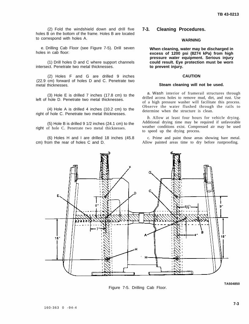
TB 43-0213
(2) Fold the windshield down and drill fiveholes B on the bottom of the frame. Holes B are locatedto correspond with holes A.
e. Drilling Cab Floor (see Figure 7-5). Drill sevenholes in cab floor:
(1) Drill holes D and C where support channelsintersect. Penetrate two metal thicknesses.
(2) Holes F and G are drilled 9 inches(22.9 cm) forward of holes D and C. Penetrate twometal thicknesses.
(3) Hole E is drilled 7 inches (17.8 cm) to theleft of hole D. Penetrate two metal thicknesses.
(4) Hole A is drilled 4 inches (10.2 cm) to theright of hole C. Penetrate two metal thicknesses.
(5) Hole B is drilled 9 1/2 inches (24.1 cm) to theright of hole C. Penetrate two metal thicknesses.
(6) Holes H and I are drilled 18 inches (45.8cm) from the rear of holes C and D.
7-3. Cleaning Procedures.
WARNING
When cleaning, water may be discharged inexcess of 1200 psi (8274 kPa) from highpressure water equipment. Serious injurycould result. Eye protection must be wornto prevent injury.
CAUTION
Steam cleaning will not be used.
a. Wash interior of framerail structures throughdrilled access holes to remove mud, dirt, and rust. Useof a high pressure washer will facilitate this process.Observe the water flushed through the rails todetermine when the structure is clean.
b. Allow at least four hours for vehicle drying.Additional drying time may be required if unfavorableweather conditions exist. Compressed air may be usedto speed up the drying process.
c. Prime and paint those areas showing bare metal.Allow painted areas time to dry before rustproofing.
TA504850Figure 7-5. Drilling Cab Floor.
7-31 6 0 - 3 6 3 0 - 9 4 - 4

TB 43-0213
Section Ill. RUSTPROOFING PROCEDURES
7-4. Rustproofing Procedures. CAUTION
CAUTION
Do not spray any portion of movingcomponents, transmission, transfer case,cylinders, pumps, valves, prop shaft,exhaust system, rubber bump stops, brake-drums, brake backing plates, parking brakelinkage, shift linkage, tires, electricalcomponents, engine linkage, or air intakesystems. Cover all areas with paper wherenecessary.
●
●
a.
NOTE
There are areas where a 10 mil wet filmthickness cannot be obtained withoutwasting a large amount of compound. Inthose areas, complete coverage of thesurface area is necessary at whateverthickness is obtainable.
For rustproofing procedures of specificcab body items, refer to Figure 7-6through Figure 7-9.
Dry Film Thickness Requirements. A five mil dryfilm thickness is required for adequate rustproofingprotection. A 10 mil wet film thickness is required toobtain a minimum five mil dry film thickness. Ifneeded, the vehicle can be resprayed to reach properthickness.
b. Spraying Pressure. The rustproofing compoundshould be applied to sheet metal and structuralmembers in even coats. Spraying pressure should be aslow as possible while maintaining an even spray pattern.An acceptable starting point is 40 psi (276 kPa), butadjustments may have to be made due to temperaturechanges and differences in rustproofing compound.Using too much pressure will waste compound bycausing overspray and excessively thick coatings.
c. Rustproofing Cab Si l ls and Doors (seeFigure 7-6).
(1) Insert 90 degree short tool into holes A, B,and C in the top of cab sill and spray in all directions.
Do not exceed 15 inches (38.1 cm), as thecompound will foul the window mechanism.
(2) Use flexible 60 degree tool to applyrustproofing compound to the lower 15 inches (38.1cm) of the inner panel of each door. Ensure that alldrain holes in the bottom of the door are open afterapplying compound.
TA504851Figure 7-6. Rustproofing Cab Sills
and Doors.
d. Rustproofing Cab Floor (see Figure 7-7).
(1) Insert flexible tool as far as possible intoholes C, D, F, G, and H of the cab floor. Spray whileslowly withdrawing tool. Repeat this procedure until therustproofing compound has been applied in all fourdirections.
(2) Insert 90 degree tool into holes A, B, and Eand spray in all directions.
(3) Use 45 degree tool to apply rustproofingcompound to seams and complete interior rear surfaceof cab floor.
(4) Coat entire underside of the cab floor usingshort rigid tool.
(5) Plug all holes except H.
7-4

TB 43-0213
Figure 7-7. Rustproofing Cab Floor.
e. Rustproofing Windshield Frame (seeFigure 7-8).
(1) Insert long rigid tool as far as it will go intoeach of the windshield vertical frame channels A. Itmay require two passes to ensure complete coverage.
(2) Lower windshield to a flat position to exposeholes D, then insert 90 degree short tool in each hole ofthe horizontal frame channels and spray in alldirections. Repeat the same procedure for holes C.
(3) Plug all holes A and C. Leave holes B and Dopen for drainage
f. Rustproofing Cowl, Hood and Dash Panel (seeFigure 7-9).
(1) Use 45 degree tool to apply rustproofingcompound to the complete cowl exterior seam.Completely coat the upper cowl panel and left- andright-hand interior cowl side panels through the freshair panels.
TA504853Figure 7-8. Rustproofing Windshield Frame.
7-5

TB 43-0213
(2) Apply rustproofing compound to entire (3) Coat the complete underside of hood, hooddash panel (engine side only). Do not coat the dash side panels, and front end.panel on the interior of the cab.
TA504854Figure 7-9. Rustproofing Cowl, Hood, and Dash Panel.
7-5. Rustproofing Inspection.
a. Check the vehicle to ensure that all areasrequiring rustproofing compound have been properlyand completely coated.
(1) Check seams, welds, corners, and boxedareas to ensure that they are adequately coated.
(2) Check wet film thickness with a wet filmthickness gage (see Figure 7-10). A wet film thicknessof 10 mils is required. In areas where a wet filmthickness of 10 mils cannot be obtained or wherethickness cannot be measured, inspect for complete-ness of coverage.
(3) Check all drain holes to ensure that they areopen.
TA504789Figure 7-10. Film Thickness Gage.
7-6

TB 43-0213
(4) Check all inspection and drilled accessholes to ensure that compound coverage is adequate(see CAUTION, paragraph 7-4).
NOTE
Plugging of access holes may be delayeduntil after vehicle inspection, if inspectionoccurs immediately after rustproofing. Ifinspection is delayed too long, rustproofingcompound may drip from access holes.
b. Plug access holes,
7-6.
●
●
Component Installation.
NOTE
Installation instructions for 2 1/2-Ton SeriesTrucks are in TM 9-2320-209-20 andTM 9-2320-209-34.
Installation instructions for 5-Ton SeriesTrucks are in TM 9-2320-211-20 andTM 9-2320-211-34.
Install all components that were removed inparagraph 7-1.
7-7/(7-8 Blank)

TB 43-0213
CHAPTER 82 1/2-TON CARGO BODY TRUCKS
Section I. PRELIMINARY PROCEDURES
8-1. Component Removal.
Remove cargo canvas and bows from cargo body trucks, as shown in Figure 8-1, if equipped (see TM 9-2320-209-20).
Figure 8-1. 2 1/2 Ton Cargo Body Trucks.
Section Il. DRILLING AND CLEANING
8-2. Drilling Procedures.
PROCEDURES
NOTE
TA504855
NOTE The M35A2C is the only cargo body configu-ration which requires drilling of the tailgate.
Unless otherwise indicated, all holes shouldbe sight drilled and should be 1/2 inch(1.3 cm) in diameter. b. Drilling Tailgate (M35A2C) (see Figure 8-2).
a. General. Referdrilling instructions.
Drill four 1/2-inch (1. 3 cm) holes A in the tailgate centerto paragraph 3-15 for general stiffener. Holes are drilled 17 1/2 inches (44.5 cm) from
one of two holes, B, which already exist.
8-1

TB 43-0213
8-3. Cleaning Procedures.
WARNING
When cleaning items, water may be dis-
a. Wash interior of framerail structures throughdrilled access holes to remove mud, dirt, and rust. Use of a high pressure washer will facilitate this process.Observe the water flushed through the rails todetermine when the structure is clean.
charged in excess of 1200 psi (8274 kPa)from high pressure water equipment. Seri- b. Allow at least four hours for vehicle drying.
ous injury could result. Eye protection must Additional drying time may be required if unfavorablebe worn to prevent injury. weather conditions exist. Compressed air may be used
to speed up the drying process.
CAUTIONc. Paint and prime those areas showing bare metal.
Steam cleaning will not be used. Allow painted areas time to dry before rustproofing.
Figure 8-2, Drilling Tailgate (M3SA2C).
Section Ill. RUSTPROOFING PROCEDURES
8-4. Rustproofing Procedures.●
CAUTION
Do not spray any portion of moving compo-nents, transmission, transfer case, cylin-ders, pumps, valves, prop shaft, exhaustsystem, rubber bump stops, brakedrums~brake backing pIates, parking brake linkage~shaft linkage, tires, electrical components,engine linkages, or air intake systems. Cov- a.
NOTE
There are areas where a 10 mil wet filmthickness cannot be obtained withoutwasting a large amount of compound. Inthose areas, complete coverage of thesurface area is necessary at whateverthickness is obtainable.
For rustproofing procedures of specificcargo body items, refer to Figure 8-3 andFigure 8-4.
Dry Film Thickness Requirements. A five mil dryer all areas with paper where necessary. film thickness is required for adequate rustproofing
8-2

TB 43-0213
protection. A 10 mil wet film thickness is required toobtain a minimum five mil dry film thickness. Ifneeded, the vehicle can be resprayed to reach properthickness.
b. Spraying Pressure. The rustproofing compoundshould be applied to sheet metal and structuralmembers in even coats. Spraying pressure should be aslow as possible while maintaining an even spray pattern.An acceptable starting point is 40 psi (276 kPa), butadjustments may have to be made due to temperaturechanges and differences in rustproofing compound.Using too much pressure will waste compound bycausing overspray and excessively thick coatings.
c. Rustproofing Tailgate (M35A2C) (seeFigure 8-3). Insert 90 degree short tool into tailgateholes A and B and spray in all directions. Plug holes.
d. Rustproofing Cargo Body (see Figure 8-4).
(1) Insert long rigid tool into each stake pocket.Spray while slowly withdrawing tool. Two passes may berequired to complete coverage of each pocket.
(2) Use 90 degree short tool to spray theinterior surfaces of the rubrail (underneath the ledge),on sides, front, and tailgate.
(3) Use flexible tool to completely cover under-body of cargo bed.
TA504857Figure 8-3. Rustproofing Tailgate (M352AC).
TA504858Figure 8-4. Rustproofing Cargo Body,
8-3

TB 43-0213
8-5. Rustproofing Inspection.
a. Check the vehicle to ensure that all areasrequiring rustproofing compound have been properlyand completely coated.
(1) Check seams, welds, corners, and boxedareas to ensure that they are adequately coated.
(2) Check wet film thickness with a wet filmthickness gage (see Figure 8-5). A wet film thickness of10 mils is required. In areas where a wet film thicknessof 10 mils cannot be obtained or where thicknesscannot be measured, inspect for completeness ofcoverage.
(3) Check all drain holes to ensure that they areopen.
(4) Check all inspection and drilled accessholes to ensure that compound coverage is adequate.
NOTE
Plugging of access holes may be delayeduntil after vehicle inspection, if inspectionoccurs immediately after rustproofing. Ifinspection is delayed too long, rustproofingcompound may drip from access holes.
b. Plug access holes.
8-6. Component Installation.
Install all the components that were removed inparagraph 8-1 (see TM 9-2320-209-20),
TA504789Figure 8-5. Film Thickness Gage.
8-4

TB 43-0213
CHAPTER 92 1/2-TON TRUCKS: DUMP BODY AND TAlLGATE
Section I. PRELIMINARY PROCEDURES
9-1. Component Removal. b. Before beginning any rustproofing procedures,
a. Figure 9-1 provides a reference illustration forremove the handles from the tailgate (see TM 9-2320-209-20).
the 2 1/2Ton Dump Truck.
TA504859Figure 9-1. 2 1/2-Ton Dump Truck (M342A2),
Section Il. DRILLING AND CLEANING PROCEDURES
9-2. Drilling Procedures.
NOTE
Unless otherwise indicated, all holes shouldbe sight drilled and should be 1/2 inch(1.3 cm) in diameter,
a. General. Refer to paragraph 3-15 for generaldrilling instructions.
b. Drilling Cab Protector Braces (see Figure 9-2).
(1) Raise the dump body enough to gain accessto the underside of the cab protector.
(2) Drill two holes A in cab protector bracesfrom the underside. Holes are located by measuring20 1/2 inches (52. 1 cm) from the sides and 17 inches(43.2 cm) from the front.
9-1
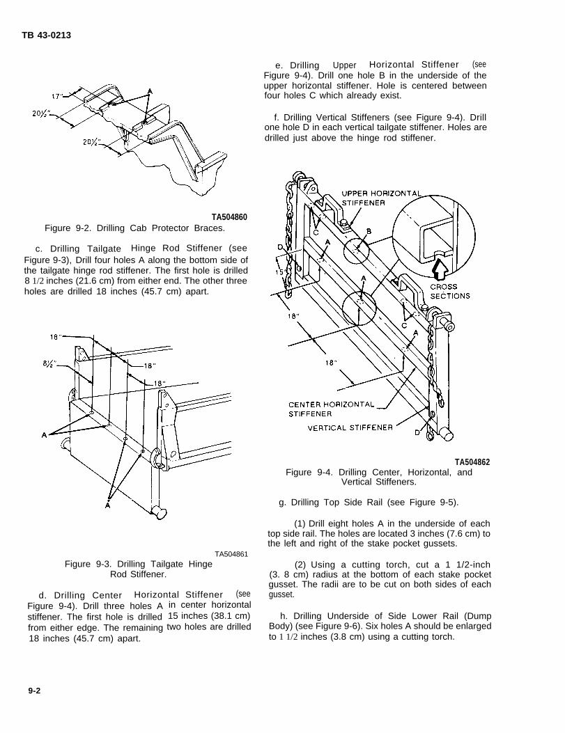
TB 43-0213
TA504860Figure 9-2. Drilling Cab Protector Braces.
c. Drilling Tailgate Hinge Rod Stiffener (seeFigure 9-3), Drill four holes A along the bottom side ofthe tailgate hinge rod stiffener. The first hole is drilled8 1/2 inches (21.6 cm) from either end. The other threeholes are drilled 18 inches (45.7 cm) apart.
TA504861Figure 9-3. Drilling Tailgate Hinge
Rod Stiffener.
d. Drilling Center Horizontal Stiffener (seeFigure 9-4). Drill three holes Astiffener. The first hole is drilledfrom either edge. The remaining18 inches (45.7 cm) apart.
9-2
in center horizontal15 inches (38.1 cm)two holes are drilled
e. Drilling Upper Horizontal Stiffener (seeFigure 9-4). Drill one hole B in the underside of theupper horizontal stiffener. Hole is centered betweenfour holes C which already exist.
f. Drilling Vertical Stiffeners (see Figure 9-4). Drillone hole D in each vertical tailgate stiffener. Holes aredrilled just above the hinge rod stiffener.
TA504862Figure 9-4. Drilling Center, Horizontal, and
Vertical Stiffeners.
g. Drilling Top Side Rail (see Figure 9-5).
(1) Drill eight holes A in the underside of eachtop side rail. The holes are located 3 inches (7.6 cm) tothe left and right of the stake pocket gussets.
(2) Using a cutting torch, cut a 1 1/2-inch(3. 8 cm) radius at the bottom of each stake pocketgusset. The radii are to be cut on both sides of eachgusset.
h. Drilling Underside of Side Lower Rail (DumpBody) (see Figure 9-6). Six holes A should be enlargedto 1 1/2 inches (3.8 cm) using a cutting torch.

TB 43-0213
Figure 9-5. Drilling Top Side Rail and Cutting Stake Pockets.
Figure 9-6. Underbody.
9-3. Cleaning Procedures.
WARNING
When cleaning, water may be discharged inexcess of 1200 psi (8274 kPa) from highpressure water equipment.could result. Eye protectionto prevent injury.
CAUTION
Serious injurymust be worn
Steam cleaning will not be used.
a. Wash the interior of structures through drilledaccess holes to remove mud, dirt, and rust. Use of ahigh pressure washer will facilitate this operation.Observe the water flushed through the rails todetermine if it is clean.
b. Allow at least four hours for vehicle drying.Additional drying time may be required if unfavorable
9-3
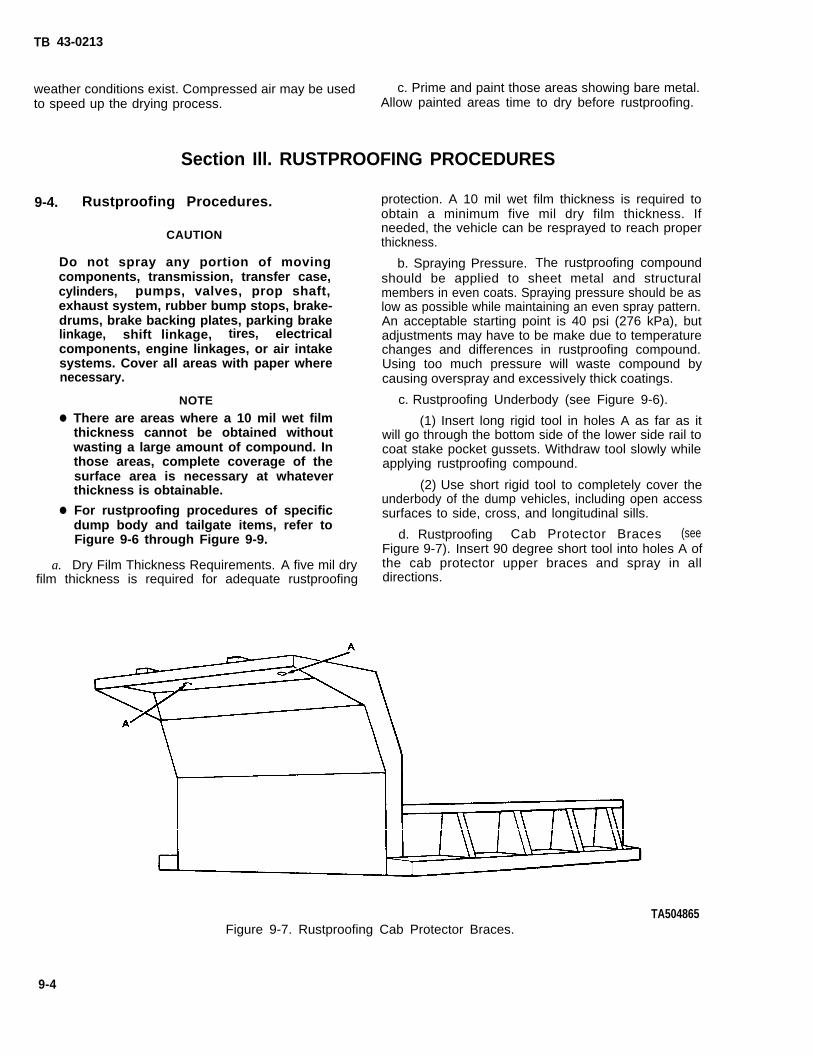
TB 43-0213
weather conditions exist. Compressed air may be used c. Prime and paint those areas showing bare metal.to speed up the drying process. Allow painted areas time to dry before rustproofing.
Section Ill. RUSTPROOFING PROCEDURES
9-4. Rustproofing Procedures.
CAUTION
Do not spray any portion of movingcomponents, transmission, transfer case,cylinders, pumps, valves, prop shaft,exhaust system, rubber bump stops, brake-drums, brake backing plates, parking brakelinkage, shift linkage, tires, electricalcomponents, engine linkages, or air intakesystems. Cover all areas with paper wherenecessary.
●
●
a.
NOTE
There are areas where a 10 mil wet filmthickness cannot be obtained withoutwasting a large amount of compound. Inthose areas, complete coverage of thesurface area is necessary at whateverthickness is obtainable.
For rustproofing procedures of specificdump body and tailgate items, refer toFigure 9-6 through Figure 9-9.
Dry Film Thickness Requirements. A five mil dryfilm thickness is required for adequate rustproofing
protection. A 10 mil wet film thickness is required toobtain a minimum five mil dry film thickness. Ifneeded, the vehicle can be resprayed to reach properthickness.
b. Spraying Pressure. The rustproofing compoundshould be applied to sheet metal and structuralmembers in even coats. Spraying pressure should be aslow as possible while maintaining an even spray pattern.An acceptable starting point is 40 psi (276 kPa), butadjustments may have to be make due to temperaturechanges and differences in rustproofing compound.Using too much pressure will waste compound bycausing overspray and excessively thick coatings.
c. Rustproofing Underbody (see Figure 9-6).
(1) Insert long rigid tool in holes A as far as itwill go through the bottom side of the lower side rail tocoat stake pocket gussets. Withdraw tool slowly whileapplying rustproofing compound.
(2) Use short rigid tool to completely cover theunderbody of the dump vehicles, including open accesssurfaces to side, cross, and longitudinal sills.
d. Rustproofing Cab Protector Braces (seeFigure 9-7). Insert 90 degree short tool into holes A ofthe cab protector upper braces and spray in alldirections.
TA504865Figure 9-7. Rustproofing Cab Protector Braces.
9-4

e. Rustproofing Tailgate (see Figure 9-8). Insert90 degree short tool into holes A (vertical tailgatestiffeners), B (tailgate hinge rod channel), C (centerhorizontal stiffener), and D (upper horizontal stiffen-er). Spray in all directions.
TA504866Figure 9-8. Rustproofing Tailgate.
TB 43-0213
f. Rustproofing Stake Pockets and Upper Side Rails(see Figure 9-9),
spray
stake
9-5.
a.
(1) Insert 90 degree short tool into holes A andin all directions.
(2) Insert long rigid tool into the base of eachpocket B. Spray while slowly withdrawing tool.
Rustproofing Inspection.
Check the vehicle to ensure that all areasrequiring rustproofing compound have been properlyand completely coated.
(1) Check seams, welds, corners, and boxedareas to ensure that they are adequately coated.
(2) Check wet film thickness with a wet filmthickness gage (see Figure 9-10). A wet film thicknessof 10 mils is required. In areas where a wet filmthickness of 10 mils cannot be obtained or wherethickness cannot be measured, inspect for complete-ness of coverage.
(3) Check all drain holes to ensure that they areopen.
(4) Check all inspection holes and drilledaccess holes to ensure that compound coverage isadequate. Use of a high intensity inspection light willenhance this process.
(5) Check vehicle to ensure that no compoundhas been applied to prohibited areas (see CAUTION,paragraph 9-4).
TA504867Figure 9-9. Rustproofing Stake Pockets and Upper Side Rails.
9-5
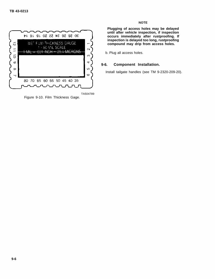
TB 43-0213
NOTE
Plugging of access holes may be delayeduntil after vehicle inspection, if inspectionoccurs immediately after rustproofing. Ifinspection is delayed too long, rustproofingcompound may drip from access holes.
b. Plug all access holes.
9-6. Component Installation.
Install tailgate handles (see TM 9-2320-209-20).
TA504789Figure 9-10. Film Thickness Gage.
9-6

TB 43-0213
CHAPTER 102 1/2-TON TRUCKS: WATER TANKERS
Section I. DRILLING AND CLEANING PROCEDURES
10-1. Drilling Procedures.
NOTE
. Figure 10-1 provides a reference illustra-tion for the 2 1/2-Ton Water Tanker.
. Unless otherwise indicated, all holesshould be sight drilled and should be1/2 inch (1.3 cm) in diameter.
a. General. Refer to paragraph 3-15 for generaldrilling instructions.
b. Drilling Superstructure (see Figure 10-2). Drill10 holes A in bottom reinforcement structures. Theseshould begin approximately 2 1/2 inches (6.4 cm) fromthe left end, and be spaced about 18 inches (45.7 cm)apart. There are two holes drilled at each interval. Oneis 1 inch (2.5 cm) from the front edge, and one is 1 inch(2.5 cm) from the rear edge.
c. Drilling Bottom Center Supports (seeFigure 10-2). Drill one hole B in each bottom centersupport. The hole is drilled 14 inches (35.6 cm) fromthe outer end of each support.
TA504868Figure 10-1. M50A2 Water Tanker.
10-1

TB 43-0213
TA504869Figure 10-2. Drilling Underbody.
10-2. Cleaning Procedures.
WARNING
When cleaning, water may be discharged inexcess of 1200 psi (8274 kPa) from highpressure water equipment. Serious injurycould result. Eye protection must be wornto prevent injury.
a. Wash the interior of structures through drilledaccess holes to remove mud, dirt, and rust. Use of ahigh pressure washer will facilitate this operation.Observe the water flushed through the rails todetermine if it is clean.
b. Allow at least four hours for vehicle drying.Additional drying time may be required if unfavorableweather conditions exist. Compressed air may be usedto speed up the drying process.
CAUTIONc. Prime and paint those areas showing bare metal.
Steam cleaning will not be used. Allow painted areas time to dry before rustproofing.
10-2

TB 43-0213
Section Il. RUSTPROOFING PROCEDURES
10-3. Rustproofing Procedures.
CAUTION
Do not spray any portion of movingcomponents, transmission, transfer case,cylinders, pumps, valves, prop shaft,exhaust system, rubber bump stops, brake-drums, brake backing plates, parking brakelinkage, shift linkage, tires, electricalcomponents, engine linkages, or air intakesystems. Cover all areas with paper wherenecessary.
NOTE
There are areas where a 10 mil wet filmthickness cannot be obtained withoutwasting a large amount of compound. Inthose areas, complete coverage of thesurface area is necessary at whateverthickness is obtainable.
For rustproofing procedures of specifictanker body items, refer to Figure 10-3and Figure 10-4.
a. Dry Film Thickness Requirements. A five mil dryfilm thickness is required for adequate rustproofingprotection. A 10 mil wet film thickness is required toobtain a minimum five mil dry film thickness. Ifneeded, the vehicle can be resprayed to reach properthickness.
b. Spraying Pressure. The rustproofing compoundshould be applied to sheet metal and structuralmembers in even coats. Spraying pressure should be aslow as possible while maintaining an even spray pattern.An acceptable starting point is 40 psi (276 kPa), butadjustments may have to be made, due to temperaturechanges and differences in rustproofing compound.Using too much pressure will waste compound bycausing overspray and excessively thick coatings.
c. Rustproofing Underbody (see Figure 10-3).
(1) Insert 90 degree short tool in holes A andspray in all directions to coat the entire interior surfaceof the center supports.
(2) Insert the same tool into holes B and sprayin all directions.
(3) Use short rigid tool to completely cover theunderbody including all open access areas.
Figure 10-3. Rustproofing Underbody,
10-3

TB 43-0213
d. Rustproofing Stake Pockets (see Figure 10-4).Insert the long rigid tool to the base of stake pockets Aand withdraw slowly while coating the entire surface.
10-4. Rustproofing Inspection.
Check the vehicle to ensure that all areas requiringrustproofing compound have been properly andcompletely coated.
a. Check seams, welds, corners, and boxed areas toensure that they are adequately coated.
b. Check wet film thickness with a wet filmthickness gage (see Figure 10-5). A wet film thicknessof 10 mils is required. In areas where a wet filmthickness of 10 mils cannot be obtained or wherethickness cannot be measured, inspect for complete-ness of coverage.
c. Check all drain holes to ensure that they areopen.
d. Check all inspection holes and drilled accessholes to ensure that compound coverage is adequate.Use of a high intensity inspection light will enhance thisprocess.
e. Check vehicle to ensure that no compound hasbeen applied to prohibited areas (see CAUTION,paragraph 10-3).
TA504789Figure 10-5. Film Thickness Gage.
Figure 10-4. Rustproofing Stake Pockets.
TA504871
10-4

TB 43-0213
CHAPTER 112 1/2-TON TRUCKS: FUEL TANKERS
Section I. DRILLING AND CLEANING PROCEDURES
11-1. Drilling Procedures. a. General. Refer to paragraphdrilling instructions,
NOTE
3-15 for general
. Figure 11-1 provides a reference illustra- b. Drilling Center Support (see Figure 11-2). Drilltion for the 2 1/2~Ton Fuel Tanker. one hole A in each bottom center support. The hole is
drilled 14 inches (35.6 cm) from the outer end of each. Unless otherwise indicated, all holessupport.should be sight drilled and should be
1/2 inch (1.3 cm) in diameter.
Figure 11-1. M49A2C Fuel Tanker.
11-1

TB 43-0213
TA504873
Figure 11-2. Drilling Center Support.
11-2. Cleaning Procedures. a. Wash the interior of framerail structures throughdrilled access holes to remove mud, dirt, and rust. Use
WARNINGof a high pressure washer will facilitate this operation.Observe the water flushed through the rails to
When cleaning, water may be discharged indetermine if it is clean.
excess of 1200 psi (8274 kPa) from highpressure water equipment. Serious injury
b. Allow at least four hours for vehicle drying.
could result. Eye protection must be worn Additional drying time may be required if unfavorable
to prevent injury. weather conditions exist. Compressed air may be usedto speed up the drying process.
CAUTIONc. Prime and paint those areas showing bare metal.
Steam cleaning will not be used. Allow painted areas time to dry before rustproofing.
11-2
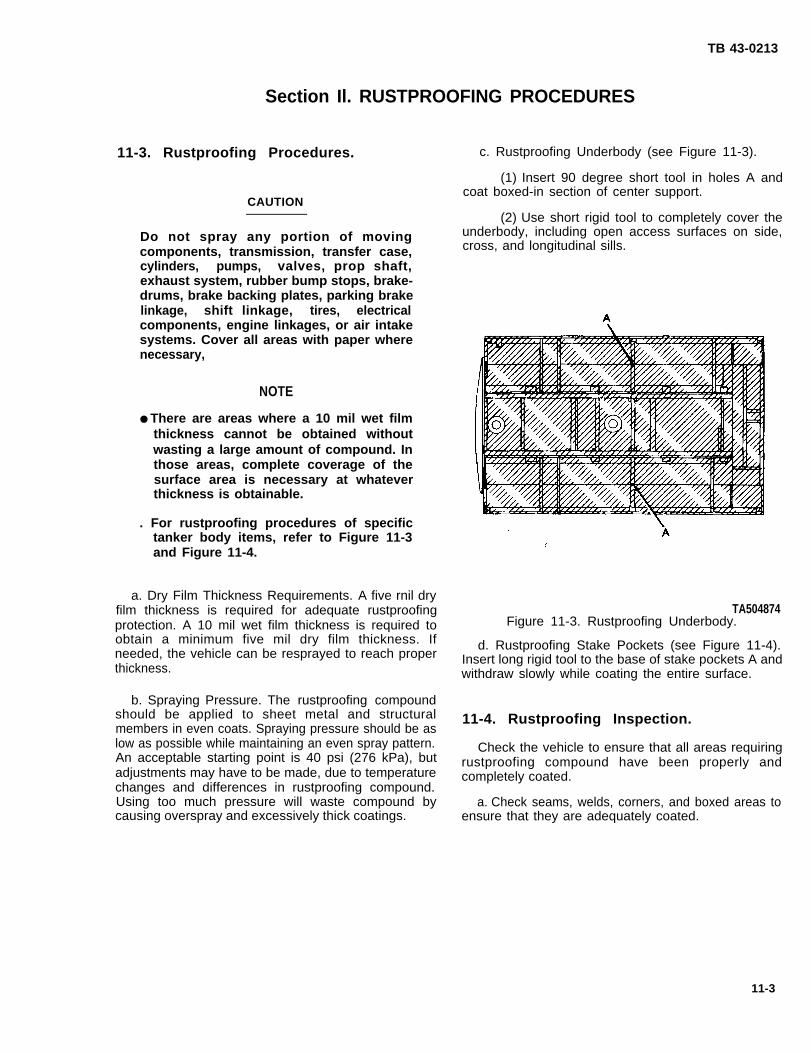
TB 43-0213
Section Il. RUSTPROOFING PROCEDURES
11-3. Rustproofing Procedures.
CAUTION
Do not spray any portion of movingcomponents, transmission, transfer case,cylinders, pumps, valves, prop shaft,exhaust system, rubber bump stops, brake-drums, brake backing plates, parking brakelinkage, shift linkage, tires, electricalcomponents, engine linkages, or air intakesystems. Cover all areas with paper wherenecessary,
NOTE
● There are areas where a 10 mil wet filmthickness cannot be obtained withoutwasting a large amount of compound. Inthose areas, complete coverage of thesurface area is necessary at whateverthickness is obtainable.
. For rustproofing procedures of specifictanker body items, refer to Figure 11-3and Figure 11-4.
a. Dry Film Thickness Requirements. A five rnil dryfilm thickness is required for adequate rustproofingprotection. A 10 mil wet film thickness is required toobtain a minimum five mil dry film thickness. Ifneeded, the vehicle can be resprayed to reach properthickness.
b. Spraying Pressure. The rustproofing compoundshould be applied to sheet metal and structuralmembers in even coats. Spraying pressure should be aslow as possible while maintaining an even spray pattern.An acceptable starting point is 40 psi (276 kPa), butadjustments may have to be made, due to temperaturechanges and differences in rustproofing compound.Using too much pressure will waste compound bycausing overspray and excessively thick coatings.
c. Rustproofing Underbody (see Figure 11-3).
(1) Insert 90 degree short tool in holes A andcoat boxed-in section of center support.
(2) Use short rigid tool to completely cover theunderbody, including open access surfaces on side,cross, and longitudinal sills.
TA504874Figure 11-3. Rustproofing Underbody.
d. Rustproofing Stake Pockets (see Figure 11-4).Insert long rigid tool to the base of stake pockets A andwithdraw slowly while coating the entire surface.
11-4. Rustproofing Inspection.
Check the vehicle to ensure that all areas requiringrustproofing compound have been properly andcompletely coated.
a. Check seams, welds, corners, and boxed areas toensure that they are adequately coated.
11-3

TB 43-0213
Figure 11-4. Rustproofing Stake Pockets.
b. Check wet film thickness with a wet filmthickness gage (see Figure 11-5). A wet film thicknessof 10 mils is required. In areas where a wet filmthickness of 10 mils cannot be obtained or wherethickness cannot be measured, inspect for complete-ness of coverage.
c. Check all drain holes to ensure that they areopen.
d. Check all inspection holes and drilled accessholes to ensure that compound coverage is adequate.Use of a high intensity inspection light will enhance thisprocess.
e. Check vehicle to ensure that no compound hasbeen applied to prohibited areas (see CAUTION,paragraph 11-3).
TA504875
TA504789Figure 11-5. Film Thickness Gage.
11-4

TB 43-0213
CHAPTER 122 1/2-TON TRUCKS: VAN BODY.
12-1. Cleaning
a. This sectiontypical 2 1/2-Ton van
Section I. CLEANING PROCEDURES
Procedures.
covers cleaning procedures forbodies. This section does not cover
procedures for expansible van bodies. A typical2 1/2Ton van body truck is shown in Figure 12-1.
WARNING
When cleaning, water may be discharged inexcess of 1200 psi (8274 kPa) from highpressure water equipment. Serious injurycould result. Eye protection must be wornto prevent injury.
CAUTION
Steam cleaning will not be used.
b. Wash the framerail structures thoroughly toremove mud, dirt, and rust. Use of a high pressurewasher will facilitate this operation.
c. Allow at least four hours for vehicle drying.Additional drying time may be required if unfavorableweather conditions exist. Compressed air may be usedto speed up the drying process.
d. Prime and paint thoseAllow painted areas time to
areas showing bare metal,dry before rustproofing.
TA504876Figure 12-1. 2 1/2-Ton Van Body (Typical).
12-1

TB 43-0213
Section Il. RUSTPROOFING PROCEDURES
12-2. Rustproofing Procedures.
CAUTION
Do not spray any portion of moving compo-nents, transmission, transfer case, cylin-ders, pumps, valves, prop shaft, exhaustsystem, rubber bump stops, brakedrums,brake backing plates, parking brake linkage,shift linkage, tires, electrical components,engine linkages, or air intake systems. Cov-er all areas with paper where necessary.
NOTE
There are areas where a 10 mil wet filmthickness cannot be obtained without wast-ing a large amount of compound. In thoseareas, complete coverage of the surfacearea is necessary at whatever thickness isobtainable.
a. Dry Film Thickness Requirements, A five mil dryfilm thickness is required for adequate rustproofingprotection. A 10 mil wet film thickness is required toobtain a minimum five mil dry film thickness. Ifneeded, the vehicle can be resprayed to reach properthickness.
b. Spraying Pressure. The rustproofing compoundshould be applied to sheet metal and structuralmembers in even coats. Spraying pressure should be aslow as possible while maintaining an even spray pattern.An acceptable starting point is 40 psi (276 kPa), butadjustments may have to be made, due to temperaturechanges and differences in rustproofing compound.Using too much pressure will waste compound bycausing overspray and excessively thick coatings.
c. Rustproofing Underbody (see Figure 12-2). Useshort rigid tool to completely cover the vehicleunderbody, including open access surfaces on side,cross, and longitudinal sills.
12-3. Rustproofing Inspection.
Check the vehicle to ensure that all areas requiringrustproofing compound have been properly andcompletely coated.
a. Check seams, welds, corners, and boxed areas toensure that they are adequately coated.
TA504877Figure 12-2. Rustproofing Underbody.
b. Check wet film thickness with a wet filmthickness gage (see Figure 12-3). A wet film thicknessof 10 roils is required. In areas where a wet filmthickness of 10 roils cannot be obtained or wherethickness cannot be measured, inspect for complete-ness of coverage.
c. Check all drain holes to ensure that they areopen.
TA504789Figure 12-3. Film Thickness Gage.
12-2

TB 43-0213
d. Check all inspection holes and drilled access e. Check vehicle to ensure that no compound hasholes to ensure that compound coverage is adequate. been applied to prohibited areas (see CAUTION,Use of a high intensity inspection light will enhance this paragraph 12-2).process.
12-3/(12-4 Blank)

TB 43-0213
CHAPTER 135-TON TRUCKS: CARGO BODY
Section I. PRELIMINARY PROCEDURES
13-1. Component Removal. b. Remove cargo canvas and bows from cargo body,
a. Figure 13-1 provides a reference illustration forif equipped (see TM 9-2320-211-20).
5-Ton Cargo Body Trucks.
TA504878Figure 13-1. 5-Ton Cargo Bodies (Typical).
Section Il. DRILLING AND CLEANING PROCEDURES
13-2. Drilling Procedures. NOTE
The dropside cargo body is the onlyNOTE configuration which requires drilling of the
tailgate.Unless otherwise indicated, all holes shouldbe sight drilled and should be 1/2 inch(1.3 cm) in diameter. b. Drilling Tailgate (Dropside Only) (see
Figure 13-2). Drill four holes A in the tailgate centerstiffener. Holes are drilled 17 1/2 inches (44. 5 cm) on
a. General. Refer to paragraph 3-15 for general center. The first hole A is drilled 17 1/2 inches (44.5 cm)drilling instructions. from one of the two holes B which already exists.
13-1

TB 43-0213
Figure 13-2. Drilling
NOTE
Holes A in stake pockets may already exist.
c. Drilling Stake Pockets (see Figure 13-3). Drill a3/4-inch (19 mm) hole in the bottom of the 12 stakepockets.
TA504879Tailgate (Dropside Only).
TA504880
Figure 13-3. Drilling Stake Pockets.
d. Drilling Underbody (see Figure 13-4). Drillone hole A in cargo body. Hole A should be centedbetween holes B which already exist.
13-3. Cleaning Procedures.
13-2
WARNING
When cleaning, water may be discharged inexcess of 1200 psi (8274 kPa) from highpressure water equipment. Serious injurycould result. Eye protectionto prevent injury.
CAUTION
Steam cleaning will not
must be worn
be used.
a. Wash the interior of framerail structures throughdrilled access holes to remove mud, dirt, and rust. Useof a high pressure washer will facilitate this process.Observe the water flushed through the rails todetermine when the structure is clean.
b. Allow at least four hours for vehicle drying.Additional drying time may be required if unfavorableweather conditions exist. Compressed air may be usedto speed up the drying process.
c. Prime and paint those areas showing bare metal.Allow painted areas time to dry before rustproofing.
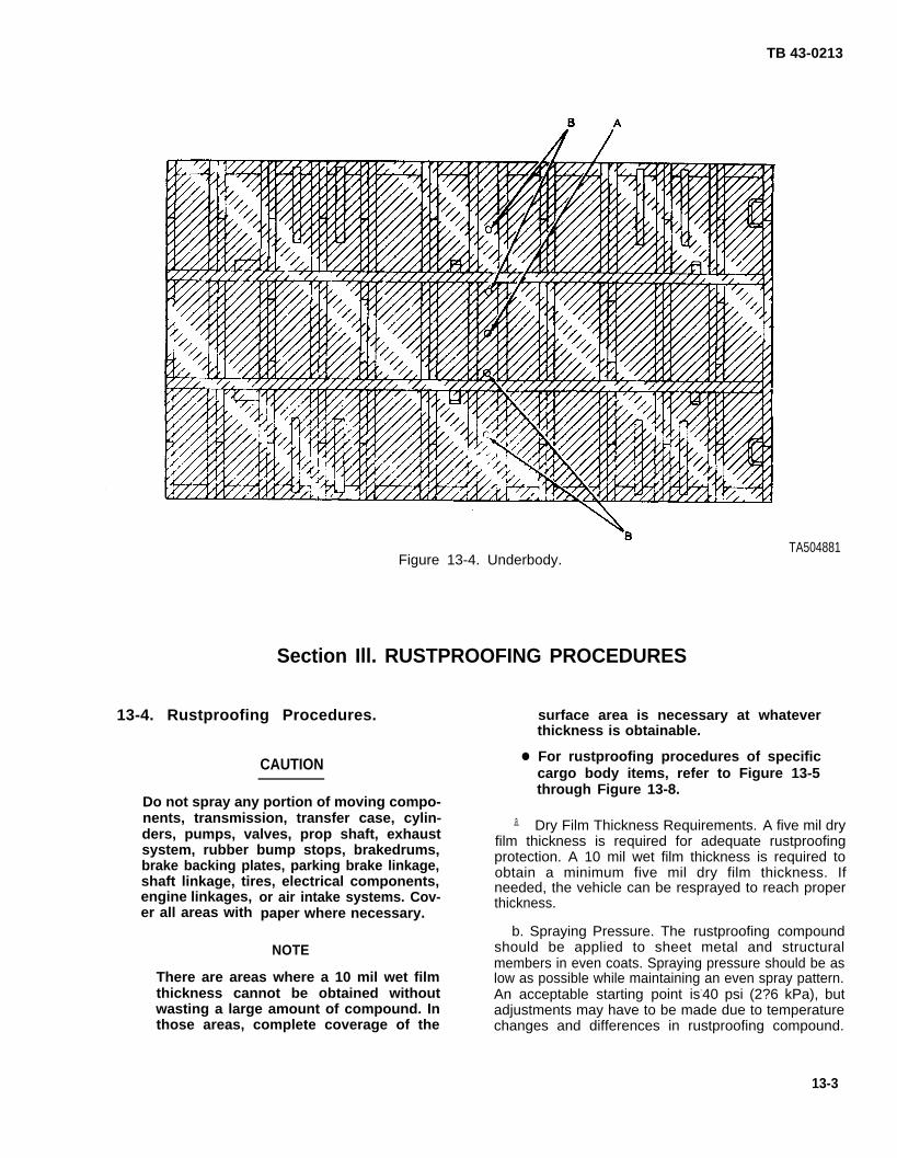
TB 43-0213
Figure 13-4. Underbody.
Section Ill. RUSTPROOFING PROCEDURES
13-4. Rustproofing Procedures.
CAUTION●
Do not spray any portion of moving compo-nents, transmission, transfer case, cylin- .a.
engine linkages,er all areas with
TA504881
surface area is necessary at whateverthickness is obtainable.
For rustproofing procedures of specificcargo body items, refer to Figure 13-5through Figure 13-8.
Dry Film Thickness Requirements. A five mil dryders, pumps, valves, prop shaft, exhaust film thickness is required for adequate rustproofingsystem, rubber bump stops, brakedrums,brake backing plates, parking brake linkage,
protection. A 10 mil wet film thickness is required toobtain a minimum five mil dry film thickness. If
shaft linkage, tires, electrical components, needed, the vehicle can be resprayed to reach properor air intake systems. Cov- thickness.paper where necessary.
b. Spraying Pressure. The rustproofing compoundNOTE should be applied to sheet metal and structural
members in even coats. Spraying pressure should be asThere are areas where a 10 mil wet film low as possible while maintaining an even spray pattern.thickness cannot be obtained without An acceptable starting point is-40 psi (2?6 kPa), butwasting a large amount of compound. In adjustments may have to be made due to temperaturethose areas, complete coverage of the changes and differences in rustproofing compound.
13-3

TB 43-0213
Using too much pressure will waste compound bycausing overspray and excessively thick coatings.
c. Rustproofing Tailgate (see Figure 13-5). Insert90 degree short tool into tailgate holes A and B andspray in all directions.
d. Rustproofing Stake Pockets and Rubrail (seeFigure 13-6).
(1) Insert long rigid tool into the base of eachstake pocket hole and spray while slowly withdrawingtool.
(2) Use 90 degree short tool to spray theinterior surfaces of the rubrail (underneath the ledge),side, front, and tailgate. Cover these surfaces with aneven coat.
TA504882
Figure 13-5. Rustproofing Tailgate.
TA504883
Figure 13-6. Rustproofing Stake Pockets and Rubrail.
e. Rustproofing Front Panel (see Figure 13-7).Insert 90 degree long tool into ends of verticalreinforcements and spray in all directions while slowlywithdrawing tool.
f. Rustproofing Underbody (see Figure 13-4).
(1) Insert 90 degree short rigid tool into holes Aand B in cargo body bottom and spray in all directions.
(2) Use short rigid tool to completely cover thebottom of the cargo body, including the open accesssurfaces of the side and cross longitudinal sills.
TA504884
Figure 13-7. Rustproofing Front Panel.
13-4

TB 43-0213
13-5. Rustproofing Inspection.
Check the vehicle to ensure that all areas requiringrustproofing compound have been properly andcompletely coated.
a. Check seams, welds, corners, and boxed areas toensure that they are adequately coated.
b. Check wet film thickness with a wet filmthickness gage (see Figure 13-8). A wet film thicknessof 10 roils is required. In areas where a wet filmthickness of 10 roils cannot be obtained or wherethickness cannot be measured, inspect for complete-ness of coverage.
c. Check all drain holes to ensure that they areopen.
d. Check all inspection holes and drilled accessholes to ensure that compound coverage is adequate.
e. Check vehicle to ensure that no compound hasbeen applied to prohibited areas (see CAUTION,paragraph 13-4).
TA504789Figure 13-8. Film Thickness Gage.
13-6. Component Installation.
Install cargo canvas and bows, if removed (seeTM 9-2320-211-20).
13-5/(13-6 Blank)
1 6 0 - 3 6 3 0 - 9 4 - 5

TB 43-0213
CHAPTER 145-TON TRUCKS: DUMP BODY AND TAlLGATE
Section I. PRELIMINARY PROCEDURES
14-1. Component Removal.
a. Figure 14-1 provides a reference illustration for a b. Prior to rustproofing, remove handles from thetypical 5-Ton Dump Truck, top of the tailgate (see TM 9-2320-211-20).
TA504885Figure 14-1, 5-Ton Dump Truck (M930).
Section Il. DRILLING AND CLEANING
14-2. Drilling Procedures.
NOTE
Unless otherwise indicated, all holes shouldbe sight drilled and should be 1/2 inch(1.3 cm) in diameter.
a. General. Refer to paragraph 3-15 for generaldrilling instructions,
b. DrillingFigure 14-2).
PROCEDURES
Cab Protector Upper Braces (see
(1) Tilt dump body up enough to gain access tothe underside of the cab protector.
(2) Drill three holes A in the underside of eachupper cab protector brace. The first hole is located10 inches (25.4 cm) from the rear. The second andthird holes are located 14 inches (35.6 cm) on center.
14-1

TB 43-0213
Figure 14-2.
NOTESteps 3 and 4 are for U.S. Marine Corpsapplications only.
TA504886
Drilling Cab Protector Upper Braces.
(3) Drill hole B in the front of each upper cabprotector brace.
(4) Drills 1 1/2-inch (3.8 cm) hole A in the rearof each upper cab protector brace (see Figure 14-3).
c. Drilling Cab Protector Cross Reinforcements(see Figure 14-4). Drill five 3/4-inch (19mm) holes A ineach cab protector cross reinforcement. The first holeis drilled 7 inches (17.8 cm) from the end. The nextfour holes are drilled 17 inches (43.2 cm) on center.
TA504887
Figure 14-3. Drilling Rear of Cab ProtectorUpper Braces.
d. Drilling Tailgate Hinge Rod Channel (seeFigure 14-5). Drill three holes A in tailgate hinge rodchannel. One hole should be centered on each sectionof the channel. All holes should be 15/16 inch (24 mm)from the inside of the tailgate.
e. Drilling Tailgate Center Horizontal Stiffener (seeFigure 14-6). Drill five holes A in center horizontalstiffener. The first hole is drilled 5 1/4 inches (13.3 cm) -
from the end. Four more holes are drilled 18 inches(45.7 cm) on center.
f. Drilling Tailgate Upper Horizontal Stiffener (seeFigure 14-7). Drill one hole A in upper horizontalstiffener, 18 inches (45.7 cm) from existing hole B.
g. Drilling Tailgate Vertical Stiffener (seeFigure 14-8). Drill one hole A in each vertical stiffen-er. The holes are drilled 1 1/2 inches (3.8 cm) from theedge and just above the hinge rod channel.
14-2
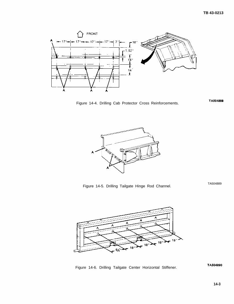
Figure 14-4. Drilling Cab Protector Cross Reinforcements.
Figure 14-5. Drilling Tailgate Hinge Rod Channel.
TB 43-0213
TA504889
Figure 14-6. Drilling Tailgate Center Horizontal Stiffener.
14-3
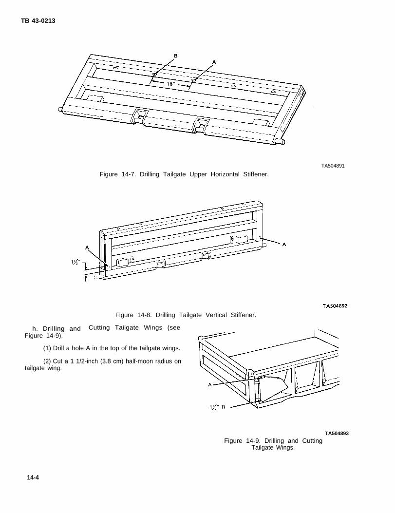
TB 43-0213
TA504891
Figure 14-7. Drilling Tailgate Upper Horizontal Stiffener.
Figure 14-8. Drilling Tailgate Vertical Stiffener.
Cutting Tailgate Wings (seeh. Drilling andFigure 14-9).
(1) Drill a hole A in the top of the tailgate wings.
(2) Cut a 1 1/2-inch (3.8 cm) half-moon radius ontailgate wing.
TA504893
Figure 14-9. Drilling and CuttingTailgate Wings.
14-4

TB 43-0213
i. Drilling Top Side Rails (see Figure 14-10), Drillsix holes A in the underside of each top side rail on thedump body. The holes are on a centerline that islocated 1 5/8 inch (4 cm) from the outer edge of the rail,The holes are centered 1 inch (2.5 cm) to the front andthe rear of the stake pocket gussets.
j. Cutting Bottom of Stake Pockets (seeFigure 14-11). Using a cutting torch, cut out a 1 1/2-inch(3. 8 cm) radius at the bottom of each stake pocketgusset. The radii are to be cut on both sides of thegusset. Repeat steps on opposite side of vehicle.
Figure 14-10. Drilling Top Side Rails.
Figure 14-11. Cutting Bottom of Stake Pockets.
TA504894
TA504895
14-5

TB 43-0213
k. DrillingFigure 14-12).diameter of 1 1/2
Bottom of Dump Body (seeEnlarge six existing holes A to ainches (3.8 cm).
14-3. Cleaning Procedures.
WARNING
When cleaning, water may be discharged inexcess of 1200 psi (8274 kPa) from highpressure water equipment. Serious injurycould result. Eye protection must be wornto prevent injury.
Steam
CAUTION
cleaning will not be used.
a. Wash the interior of structures through drilledaccess holes to remove mud, dirt, and rust. Use of ahigh pressure washer will facilitate this process. Observethe water flushing through the rails to determine when itis clean.
b. Allow at least four hours for vehicle drying.Additional drying time may be required if unfavorableweather conditions exist. Compressed air may be usedto speed up the drying process.
c. Prime and paint those areas showing bare metal.Allow painted areas time to dry before rustproofing.
Figure 14-12. Bottom of Dump Body.
14-6
TA504896
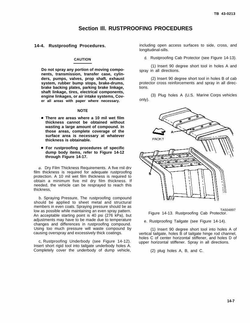
TB 43-0213
Section Ill. RUSTPROOFING PROCEDURES
14-4. Rustproofing Procedures.
CAUTION
Do not spray any portion of moving compo-nents, transmission, transfer case, cylin-ders, pumps, valves, prop shaft, exhaustsystem, rubber bump stops, brake-drums,brake backing plates, parking brake linkage,shaft linkage, tires, electrical components,engine linkages, or air intake systems, Cov-er all areas with paper where necessary.
NOTE
There are areas where a 10 mil wet filmthickness cannot be obtained withoutwasting a large amount of compound. Inthose areas, complete coverage of thesurface area is necessary at whateverthickness is obtainable.
For rustproofing procedures of specificdump body items, refer to Figure 14-12through Figure 14-17.
Dry Film Thickness Requirements. A five rnil drvfilm thickness is required for adequate rustproofingprotection. A 10 mil wet film thickness is required toobtain a minimum five mil dry film thickness. Ifneeded, the vehicle can be resprayed to reach thisthickness,
b. Spraying Pressure, The rustproofing compoundshould be applied to sheet metal and structuralmembers in even coats. Spraying pressure should be aslow as possible while maintaining an even spray pattern.An acceptable starting point is 40 psi (276 kPa), butadjustments may have to be made due to temperaturechanges and differences in rustproofing compound.Using too much pressure will waste compound bycausing overspray and excessively thick coatings.
c, Rustproofing Underbody (see Figure 14-12).Insert short rigid tool into tailgate underbody holes A.Completely cover the underbody of dump vehicle,
including open access surfaces to side, cross, andlongitudinal-sills.
d.
spray
Rustproofing Cab Protector (see Figure 14-13).
(1) Insert 90 degree short tool in holes A andin all directions.
(2) Insert 90 degree short tool in holes B of cabprotector cross reinforcementstions.
(3) Plug holes A (U.S.only).
and spray in all direc-
Marine Corps vehicles
TA504897Figure 14-13. Rustproofing Cab Protector.
e. Rustproofing Tailgate (see Figure 14-14).
(1) Insert 90 degree short tool into holes A ofvertical tailgate, holes B of tailgate hinge rod channel,holes C of center horizontal stiffener, and holes D ofupper horizontal stiffener. Spray in all directions.
(2) plug holes A, B, and C.
14-7

TB 43-0213
TA504898Figure 14-14. Rustproofing Tailgate.
f. Rustproofing Lower Side Rail (seeFigure 14-15). Insert 90 degree short rigid tool intoopenings A and holes B in lower side rail. Spray in alldirections.
TA504900Figure 14-16. Rustproofing Side Rail and
Stake Pockets.
TA504899 (2) Insert long rigid tool into base of stake
Figure 14-15. Rustproofing Lower pockets B. Spray while withdrawing tool.Side Rail.
h. Rustproofing Tailgate Wings (see Figure 14-17).
g. Rustproofing Side Rail and Stake Pockets (seeFigure 14-16). (1) Insert 90 degree short tool into hole A of
wing top and spray in all directions.
(1) Insert 90 degree short tool into holes Alocated in upper side rail. Spray in all directions. (2) Plug hole A.
14-8

TA504901Figure 14-17. Rustproofing Tailgate Wings.
14-5. Rustproofing Inspection.
Check the vehicle to ensure that all areas requiringrustproofing compound have been properly andcompletely coated.
a. Check seams, welds, corners, and boxed areas toensure that they are adequately coated.
b. Check wet film thickness with a wet filmthickness gage (see Figure 14-18). A wet film thicknessof 10 mils is required. In areas where a wet filmthickness of 10 mils cannot be obtained or wherethickness cannot be measured, inspect for complete-ness of coverage.
TB 43-0213
c. Check all drain holes to ensure that they areopen.
d.holes
e.been
Check all inspection holes and drilled accessto ensure that compound coverage is adequate.
Check vehicle to ensure that no compound hasapplied to prohibited areas (see CAUTION,
paragraph 14-4). -
TA504789Figure 14-18. Film Thickness Gage
14-6. Component Installation.
Install handles to top of tailgate (see TM 9-2320-211-20).
14-9/(14-10 Blank)

TB 43-0213
CHAPTER 155-TON TRUCKS: EXPANSIBLE VAN BODY
Section I. DRILLING AND CLEANING PROCEDURES
15-1. Drilling Procedures. following will provide placement measurements forholes being drilled:
NOTE (1) Drill one hole 18 inches (45.7 cm) from the
Unless otherwise indicated, all holes should front edge.
be sight drilled and should be 1/2 inch (2) Drill three more holes 18 inches (45.7 cm)(1.3 cm) in diameter. apart.
a. General. This section covers drilling and cleaning (3) Drill one more hole 114 inches (289.6 cm)from front edge.instructions for typical expansible van bodies. For other
van body types, refer to chapter 12. Refer to para- (4) Drill another hole 18 inches (45.7 cm) fromgraph 3-15 for general drilling instructions. the rear edge of the body,
b. Drilling Bottom Side Rails (see Figure 15-1). (5) Drill two more holes 18 inches (45.7 cm)Drill eight holes A in each bottom side rail. The apart.
Figure 15-1. Drilling Bottom Side Rails.TA504902
15-1
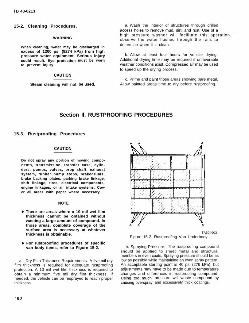
TB 43-0213
15-2. Cleaning Procedures. a. Wash the interior of structures through drilledaccess holes to remove mud, dirt, and rust. Use of ahigh pressure washer will facil itate this operation. -
WARNING observe the water flushed through the rails to
When cleaning, water may be discharged indetermine when it is clean.
excess of 1200 psi (8274 kPa) from highpressure water equipment. Serious injury b. Allow at least four hours for vehicle drying.
could result. Eye protectionto prevent injury.
CAUTION
Steam cleaning will not
must be worn Additional drying time may be required if unfavorableweather conditions exist. Compressed air may be usedto speed up the drying process.
c. Prime and paint those areas showing bare metal.be used. Allow painted areas time to dry before rustproofing.
Section Il. RUSTPROOFING PROCEDURES
15-3. Rustproofing Procedures.
CAUTION
Do not spray any portion of moving compo-nents, transmission, transfer case, cylin-ders, pumps, valves, prop shaft, exhaustsystem, rubber bump stops, brakedrums,brake backing plates, parking brake linkage,shift linkage, tires, electrical components,engine linkages, or air intake systems. Cov-er all areas with paper where necessary.
●
●
a.
NOTE
There are areas where a 10 mil wet filmthickness cannot be obtained withoutwasting a large amount of compound. Inthose areas, complete coverage of thesurface area is necessary at whateverthickness is obtainable.
For rustproofing procedures of specificvan body items, refer to Figure 15-2.
Dry Film Thickness Requirements. A five mil dryfilm thickness is required for adequate rustproofingprotection. A 10 mil wet film thickness is required toobtain a minimum five mil dry film thickness. Ifneeded, the vehicle can be resprayed to reach properthickness.
TA504903Figure 15-2. Rustproofing Van Underbody.
b. Spraying Pressure. The rustproofing compoundshould be applied to sheet metal and structuralmembers in even coats. Spraying pressure should be aslow as possible while maintaining an even spray pattern.An acceptable starting point is 40 psi (276 kPa), butadjustments may have to be made due to temperaturechanges and differences in rustproofing compound.Using too muchcausing overspray
pressure will waste compound byand excessively thick coatings.
15-2

c. Rustproofing Van Underbody,
(1) Insert 90 degree short tool into holes A ofside rails and spray in all directions.
(2) Use short rigid tool to completely cover theunderbody of van, including open access surfaces toside, cross, and longitudinal sills.
15-4. Rustproofing Inspection.
Check the vehicle to ensure that all areas requiringrustproofing compound have been properly andcompletely coated.
a. Check seams, welds, corners, and boxed areas toensure that they are adequately coated,
b. Check wet film thickness with a wet filmthickness gage (see Figure 15-3). A wet film thicknessof 10 mils is required. In areas where a wet filmthickness of 10 mils cannot be obtained or wherethickness cannot be measured, inspect for complete-ness of coverage.
c. Check all drain holes to ensure that they areopen.
d. Check all inspection holes and drilled accessholes to ensure that compound coverage is adequate,
TB 43-0213
Use of a high intensity inspection light will enhance thisprocess.
e. Check vehicle to ensure that no compound hasbeen applied to prohibited areas (see CAUTION,paragraph 15-3).
TA504789Figure 15-3. Film Thickness Gage
15-3/(15-4 Blank)

TB 43-0213
CHAPTER 165-TON TRUCKS: WRECKER BODY
16-1. Drilling
The 5-Ton
Section I. DRILLING AND CLEANING PROCEDURES
Procedures.
NOTE
Wrecker discussed in thischapter is illustrated in Figure 16-1.
a. General. Refer to paragraph 3-15 for generaldrilling instructions.
b. Drilling Underbody (see Figure 16-2). Drill one1/2-inch (1. 3 cm) hole A in each side support. Holeshould be drilled 18 inches (45.7 cm) from the outerend of the support. Holes B already exist.
16-2. Cleaning Procedures.
WARNING
Figure 16-1. 5-Ton Wrecker (A4936).TA504904
When cleaning, water may be discharged inexcess of 1200 psi (8274 kPa) from highpressure water equipment. Serious injurycould result. Eye protection must be wornto prevent injury.
CAUTION
Steam cleaning will not be used.
a. Wash the interior of structures through drilledaccess holes to remove mud, dirt, and rust. Use of ahigh pressure washer will facilitate this operation.Observe the water flushed through the rails todetermine when it is clean.
b. Allow at least four hours for vehicle drying.Additional drying time may be required if unfavorableweather conditions exist. Compressed air may be usedto speed up the drying process.
c. Prime and paint those areas showing bare metal.Allow painted areas time to dry before rustproofing.
16-1
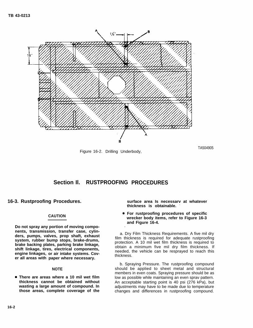
TB 43-0213
Figure 16-2.
Section Il.
16-3. Rustproofing Procedures.
CAUTION
Drilling Underbody,
RUSTPROOFING
Do not spray any portion of moving compo- .nents, transmission, transfer case, cylin-
engine linkages,er all areas with
PROCEDURES
TA504905
surface area Is necessarv at whateverthickness is obtainable. -
For rustproofing procedures of specificwrecker body items, refer to Figure 16-3and Figure 16-4.
ders, pumps, valves, prop shaft, exhaust a. Dry Film Thickness Requirements. A five mil dryfilm thickness is required for adequate rustproofingsystem, rubber bump stops, brake-drums,
brake backing plates, parking brake linkage, protection. A 10 mil wet film thickness is required to
shift linkage, tires, electrical components, obtain a minimum five mil dry film thickness. If
or air intake systems. Cov- needed, the vehicle can be resprayed to reach thisthickness.
paper where necessary.b. Spraying Pressure. The rustproofing compound
NOTE should be applied to sheet metal and structuralmembers in even coats. Spraying pressure should be as
There are areas where a 10 mil wet film low as possible while maintaining an even sprav pattern.thickness cannot be obtained without An acceptable starting point is 40 psi (276 kPa), butwasting a large amount of compound. In adjustments may have to be made due to temperaturethose areas, complete coverage of the changes and differences in rustproofing compound.
16-2

Using too muchcausing overspray
pressure will waste compoundand excessively thick coatings.
by
c. Rustproofing Underbody (see Figure 16-3).
(1) Insert 90 degree short tool into holes A andB of side supports and spray in all directions.
TB 43-0213
(2) Use short rigid tool to completely cover theunderbody of the wrecker, including opensurfaces to side, cross, and longitudinal sills.
d. Rustproofing Stake Pockets (see FigureInsert long rigid tool into base of stake pocketsspray in all directions as tool is withdrawn.
access
16-4).A and
16-4. Rustproofing Inspection.
Check the vehicle to ensure that all areas requiringrustproofing compound have been properly andcompletely coated.
a. Check seams, welds, corners, and boxed areas toensure that they are adequately coated.
b. Check wet film thickness with a wet filmthickness gage (see Figure 16-5). A wet film thicknessof 10 mils is required. In areas where a wet filmthickness of 10 mils cannot be obtained or wherethickness cannot be measured, inspect for complete-ness of coverage.
c. Check all drain holes to ensure that they areopen.
TA504907Figure 16-4. Rustproofing Stake Pockets.
16-3

TB 43-0213
d. Check all inspection holes and drilled accessholes to ensure that compound coverage is adequate.Use of a high intensity inspection light will enhance thisprocess.
e. Check vehicle to ensure that no compound hasbeen applied to prohibited areas (see CAUTION,paragraph 16-3).
TA504789Figure 16-5. Film Thickness Gage.
16-4
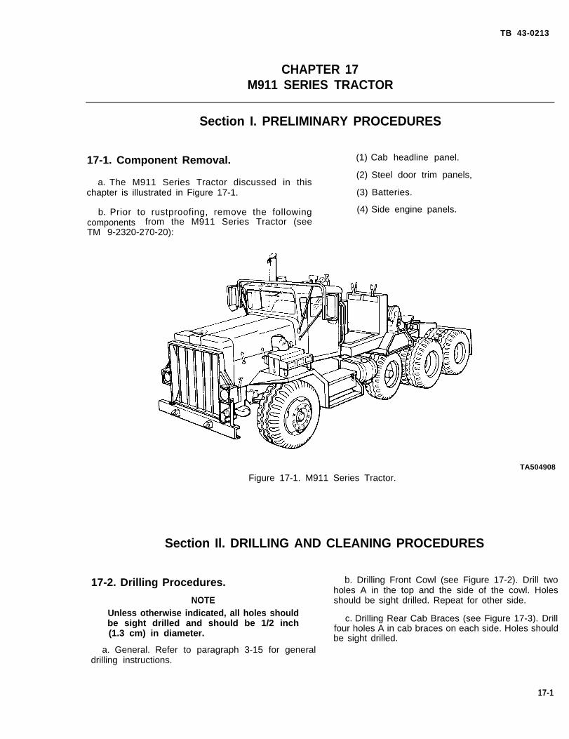
TB 43-0213
CHAPTER 17M911 SERIES TRACTOR
Section I. PRELIMINARY PROCEDURES
17-1. Component Removal. (1) Cab headline panel.
(2) Steel door trim panels,a. The M911 Series Tractor discussed in this
chapter is illustrated in Figure 17-1. (3) Batteries.
b. Prior to rustproofing, remove the following (4) Side engine panels.components from the M911 Series Tractor (seeTM 9-2320-270-20):
TA504908
Figure 17-1. M911 Series Tractor.
Section Il. DRILLING AND CLEANING PROCEDURES
17-2. Drilling Procedures. b. Drilling Front Cowl (see Figure 17-2). Drill twoholes A in the top and the side of the cowl. Holes
NOTE should be sight drilled. Repeat for other side.Unless otherwise indicated, all holes shouldbe sight drilled and should be 1/2 inch c. Drilling Rear Cab Braces (see Figure 17-3). Drill
(1.3 cm) in diameter. four holes A in cab braces on each side. Holes shouldbe sight drilled.
a. General. Refer to paragraph 3-15 for generaldrilling instructions.
17-1

TB 43-0213
TA504909Figure 17-2. Drilling Front Cowl.
17-3. Cleaning Procedures.
WARNING
When cleaning, water may be discharged inexcess of 1200 psi (8274 kPa) from highpressure water equipment. Serious injurycould result. Eye protection must be wornto prevent injury.
CAUTION
Steam cleaning will not be used.
a. Wash the interior of framerail structures throughdrilled access holes to remove mud, dirt, and rust. Useof a high pressure washer will facilitate this operation.Observe the water flushed through the rails to deter-mine when it is clean.
b. Allow at least four hours for vehicle drying. Additional drying time may be required if unfavorableweather conditions exist. Compressed air may be usedto speed up the drying process.
c. Prime and paint those areas showing bare metal,Allow painted areas time to dry before rustproofing.
TA50491OFigure 17-3. Drilling Rear Cab Braces.
Section Ill. RUSTPROOFING PROCEDURES
17-4. Rustproofing Procedures.●
CAUTION
Do not spray any portion of moving compo-nents, transmission, transfer case, cylin-ders, pumps, valves, prop shaft, exhaust system, rubber bump stops, brakedrums,brake backing plates, parking brake linkage,shift linkage, tires, electrical components,engine linkages, or air intake systems. Cov- a.
NOTE
There are areas where a 10 mil wet filmthickness cannot be obtained withoutwasting a large amount of compound. Inthose areas, complete coverage of thesurface area is necessary at whateverthickness is obtainable.
For rustproofing procedures of specifictractor items, refer to Figure 17-4through Figure 17-12.
Dry Film Thickness Requirements. A five mil dryer all areas with paper where necessary. film thickness is required for adequate rustproofing pro-
17-2

TB 43-0213
tection. A 10 mil wet film thickness is required to obtaina minimum five mil dry film thickness. If needed, thevehicle can be resprayed to reach proper thickness.
b. Spraying Pressure. The rustproofing compoundshould be applied to sheet metal and structuralmembers in even coats. Spraying pressure should be aslow as possible while maintaining an even spray pattern.An acceptable starting point is 40 psi (276 kPa), butadjustments may have to be made due to temperaturechanges and differences in rustproofing compound.Using too much pressure will waste compound bycausing overspray and excessively thick coatings.
c. Rustproofing Hood, Grille, and Bumper (seeFigure 17-4). Use 90 degree short tool to completelycoat the rear side of the grille and radiator brace, theinside of the front bumper, and the inner panel of thehood.
TA504911Figure 17-4, Rustproofing Hood, Grille,
and Bumper.
d. Rustproofing Engine Side Panels (seeFigure 17-5). Use short rigid tool to completely coatthe rear side of engine side panels.
e.
frontspray
Rustproofing Front Fenders (see Figure 17-6),
(1) Insert 90 degree short tool in holes A infender supports, then loosen top fender bolts tobetween fenders and supports.
(2) Use the same tool to completely coat theunderside of the fender, including all supports.
TA504912Figure 17-5. Rustproofing Engine
Side Pane!s.
TA504913Figure 17-6. Rustproofing Front Fenders,
f. Rustproofing Cowl (see Figure 17-7).
(1) Insert 90 degree short tool into holes A andspray cowl in all directions.
TA504914Figure 17-7. Rustproofing Cowl.
17-3

TB 43-0213
(2) Use the same tool to completely coat theback side of the cowl side panels. Gain access to thecowl side panels by inserting the tool under thedashboard on the inside of the cab and sprayingforward to the left, right, up, and down.
g. Rustproofing Roof (see Figure 17-8). Use shortrigid tool to completely coat roof inner panel A,including all supports.
TA504915Figure 17-8. Rustproofing Roof.
h. Rustproofing Lower and Rear Door Frame (seeFigure 17-9).
(1) Insert flexible tool into existing opening inthe rear pillar as far as possible, then spray in alldirections while slowly withdrawing tool.
(2) Use 90 degree short tool to completely coatthe underside of the lower door frame.
Figure 17-9.
17-4
TA504916Rustproofing Lower and Rear
Door Frame.
(3) Insert 90 degree tool in holes A in the rearcab braces and spray in all directions.
CAUTION
Roll up windows. Do not coat any part of thewindow mechanisms while spraying.
i. Rustproofing Doors (see Figure 17-10). Insert90 degree short tool through existing openings in theinside door panel A and completely coat inner panels ofdoors.
TA504917Figure 17-10. Rustproofing Doors.
j. Rustproofing Battery Box (see Figure 17-11),Use the 90 degree short tool with the cone spray tip tocoat the interior of the battery box A, including cover.
TA504918Figure 17-11. Rustproofing Battery Box.

TB 43-0213
k. Rustproofing Underbody (Typical) (seeFigure 17-12).
(1) Use short rigid tool to completely coat theunderbody.
(2) Use 90 degree short tool to coat any areasinaccessible with the straight tool. These areas includeframe channels and around rear fender flanges.
TA504919Figure 17-12. Rustproofing Underbody.
17-5. Rustproofing Inspection.
a. Check the vehicle to ensure that all areasrequiring rustproofing compound have been properlyand completely coated.
(1) Check seams, welds, corners, and boxedareas to ensure that they are adequately coated.
(2) Check wet film thickness with a wet filmthickness gage (see Figure 17- 13). A wet film thicknessof 10 roils is required. In areas where a wet filmthickness of 10 roils cannot be obtained or wherethickness cannot be measured, inspect for complete-ness of coverage.
TA504789Figure 17-13. Film Thickness Gage.
(3) Check all drain holes to ensure that they areopen.
(4) Check all inspection holes and drilledaccess holes to ensure that compound coverage isadequate. Use of a high intensity inspection light willenhance this process.
(5) Check vehicle to ensure that no compoundhas been applied to prohibited areas (see CAUTION,paragraph 17-4).
NOTE
Plugging of access holes may be delayeduntil after vehicle inspection, if inspectionoccurs immediately after rustproofing. Ifinspection is delayed too long, rustproofingcompound may drip from access holes.
b. Plug access holes.
17-6. Component Installation.
Install all components that were removed inparagraph 17-1 (see TM 9-2320-270-20).
17-5/(17-6 Blank)

TB 43-0213
CHAPTER 18M915 SERIES TRACTOR
Section I. PRELIMINARY PROCEDURES
18-1. Component Removal. (1) Cab headline panel.
a. The M915 Series Tractor discussed in this (2) Door trim panels.chapter is illustrated in Figure 18-1.
b. Prior to rustproofing, remove the following(3) Firewall insulation.
components (see TM 9-2320-273-20):
TA504920Figure 18-1. M915 Series Tractor.
Section Il. DRILLING AND CLEANING PROCEDURES
18-2. Drilling Procedures.
NOTE
Unless otherwise indicated, all holes shouldbe sight drilled and should be 1/2 inch(1.3 cm) in diameter.
a. General. Refer to paragraph 3-15 for generaldrilling instructions.
b. Drilling Headlamps (see Figure 18-2). Drill twoholes A in each headlamp housing.
18-1
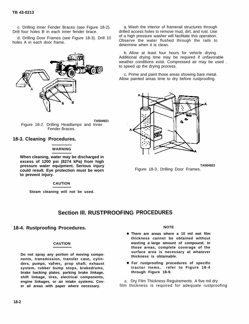
TB 43-0213
c. Drilling Inner Fender Braces (see Figure 18-2).Drill four holes B in each inner fender brace.
d. Drilling Door Frames (see Figure 18-3). Drill 10holes A in each door frame.
TA504921Figure 18-2. Drilling Headlamps and Inner
Fender Braces.
18-3. Cleaning Procedures.
WARNING
When cleaning, water may be discharged inexcess of 1200 psi (8274 kPa) from highpressure water equipment. Serious injurycould result. Eye protection must be wornto prevent injury.
CAUTION
Steam cleaning will not be used.
a. Wash the interior of framerail structures throughdrilled access holes to remove mud, dirt, and rust. Useof a high pressure washer will facilitate this operation.Observe the water flushed through the rails todetermine when it is clean.
b. Allow at least four hours for vehicle drying.Additional drying time may be required if unfavorable weather conditions exist. Compressed air may be used .to speed up the drying process.
c. Prime and paint those areas showing bare metal.Allow painted areas time to dry before rustproofing.
Section Ill. RUSTPROOFING
TA504922Figure 18-3. Drilling Door Frames.
18-4. Rustproofing Procedures.
CAUTION
Do not spray any portion of moving compo-nents, transmission, transfer case, cylin-ders, pumps, valves, prop shaft, exhaustsystem, rubber bump stops, brakedrums,brake backing plates, parking brake linkage,shift linkage, tires, electrical components,engine linkages, or air intake systems. Cov- a.
PROCEDURES
NOTE
There are areas where a 10 mil wet filmthickness cannot be obtained withoutwasting a large amount of compound. Inthose areas, complete coverage of thesurface area is necessary at whateverthickness is obtainable.
For rustproofing procedures of specifictractor i tems, refer to Figure 18-4through Figure 18-9.
Dry Film Thickness Requirements. A five mil drver ail areas with paper where necessary. film thickness is required for adequate rustproofing
18-2

TB 43-0213
protection. A 10 mil wet film thickness is required toobtain a minimum five mil dry film thickness. Ifneeded, the vehicle can be resprayed to reach properthickness.
b. Spraying Pressure. The rustproofing compoundshould be applied to sheet metal and structuralmembers in even coats. Spraying pressure should be aslow as possible while maintaining an even spray pattern.An acceptable starting point is 40 psi (276 kPa), butadjustments may have to be made due to temperaturechanges and differences in rustproofing compound.Using too much pressure will waste compound bycausing overspray and excessively thick coatings.
c. Rustproofing Headlamps and Fenders (seeFigure 18-4).
(1) Insert 90 degree short tool into holes A ofheadlamps and spray in all directions.
(2) Use the same tool to completely cover theunderside of the fenders, then insert the tool intofender brace holes B and spray in all directions.
d. Rustproofing Engine Compartment (seeFigure 18-5).
(1) Use 90 degree short tool to completelycover the inside of the hood, the radiator brace, andthe engine compartment side panels.
(2) Insert flexible short tool into the hood braceends as far as possible, then spray slowly whilewithdrawing tool.
(3) Use 90 degree short tool to completelycover the firewall.
Figure 18-4. Rustproofing Headlamps and Fenders.
Figure 18-5. Rustproofing Engine Compartment.
TA504923
TA504924
18-3

TB 43-0213
e. Rustproofing Cowl (see Figure 18-6).
(1) Use 90 degree short tool to completelycover the inside area of the cowl vent.
(2) Use short rigid tool to completely cover theinside of the cowl. Gain access from under theinstrument panel,
f. Rustproofing Roof (see Figure 18-7).
(1) Insert 90 degree short tool into holes A inthe roof panel and spray in all directions.
(2) Use the same tool to completely cover roofboxed sections.
g. Rustproofing Door Frames (see Figure 18-3).Insert 90 degree short tool into holes A in door frameand spray in all directions. Plug all holes.
TA504925Figure 18-6. Rustproofing Cowl.
TA504926Figure 18-7. Rustproofing Roof.
h. Rustproofing Doors (see Figure 18-8). Roll underbody.window up, then insert 90 degree short tool throughexisting holes A in inner door panel openings and spray (2) Use 90 degree short tool to cover all areasin all directions. of the underbody that are inaccessible with the short
rigid tool. These areas include the inside of framei. Rustproofing Underbody (Typical) (see channels and the body perimeter siderails.
Figure 18-9).(3) Use the same tool to coat entire rear side of
(1) Use short rigid tool to completely coat the the front bumper.
18-4

TB 43-0213
TA504927Figure 18-8. Rustproofing Doors.
TA504928Figure 18-9. Rustproofing Underbody.
18-5. Rustproofing Inspection.
a. Check the vehicle to ensure that all areasrequiring rustproofing compound have been properlyand completely coated.
(1) Check seams, welds, corners, and boxedareas to ensure that they are adequately coated.
(2) Check wet film thickness with a wet filmthickness gage (see Figure 18- 10). A wet film thicknessof 10 roils is required. In areas where a wet filmthickness of 10 roils cannot be obtained or wherethickness cannot be measured, inspect for complete-ness of coverage.
TA504789Figure 18-10. Film Thickness Gage.
(3) Check all drain holes to ensure that they areopen.
(4) Check all inspection holes and drilledaccess holes to ensure that compound coverage isadequate. Use of a high intensity inspection light willenhance this process.
(5) Check vehicle to ensure that no compoundhas been applied to prohibited areas (see CAUTION,paragraph 18-4).
NOTE
Plugging of access holes may be delayeduntil after vehicle inspection, if inspectionoccurs immediately after rustproofing. If in-spection is delayed too long, rustproofingcompound may drip from access holes.
b. Plug access holes.
18-6. Component Installation.
Install all components that were removed inparagraph 18-1 (see TM 9-2320-273-20).
18-5/ (18-6 Blank)
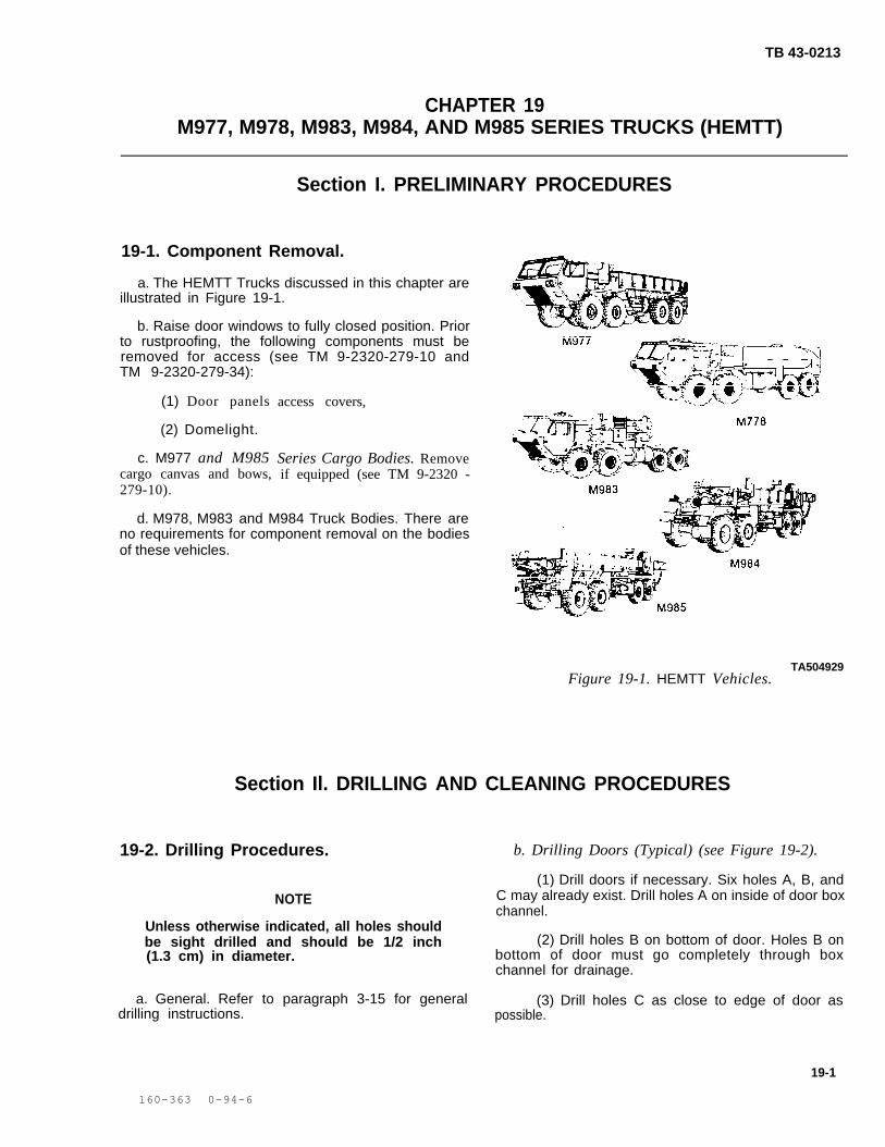
TB 43-0213
CHAPTER 19M977, M978, M983, M984, AND M985 SERIES TRUCKS (HEMTT)
Section I. PRELIMINARY PROCEDURES
19-1. Component Removal.
a. The HEMTT Trucks discussed in this chapter areillustrated in Figure 19-1.
b. Raise door windows to fully closed position. Priorto rustproofing, the following components must beremoved for access (see TM 9-2320-279-10 andTM 9-2320-279-34):
(1) Door panels
(2) Domelight.
c. M977 and M985cargo canvas and bows,279-10).
access covers,
Series Cargo Bodies. Removeif equipped (see TM 9-2320 -
d. M978, M983 and M984 Truck Bodies. There areno requirements for component removal on the bodiesof these vehicles.
TA504929Figure 19-1. HEMTT Vehicles.
Section Il. DRILLING AND CLEANING PROCEDURES
19-2. Drilling Procedures. b. Drilling Doors (Typical) (see Figure 19-2).
(1) Drill doors if necessary. Six holes A, B, andNOTE C may already exist. Drill holes A on inside of door box
channel.Unless otherwise indicated, all holes shouldbe sight drilled and should be 1/2 inch (2) Drill holes B on bottom of door. Holes B on(1.3 cm) in diameter. bottom of door must go completely through box
channel for drainage.
a. General. Refer to paragraph 3-15 for general (3) Drill holes C as close to edge of door asdrilling instructions. possible.
19-1
160-363 0-94-6

Figure 19-2.
Figure 19-4.
TB 43-0213
19-2

g. Drilling Tubular Cargo Side Panels (M984) (seeFigure 19-6).
(1) Open cargo side panel.
(2) Drill three holes A on bottom of panels,Holes A may already exist.
(3) Drill two holes B.
TB 43-0213
h. M977, M978, M983, and M985 Series Bodies,There are no drilling procedures specified for thesebodies. Holes are either predrilled or not required.
19-3. Cleaning Procedures.
Figure 19-6. Drilling TubularPanels (M984).
Section III
TA504934Cargo Side
WARNING
When cleaning, water may be discharged inexcess of 1200 psi (8274 kPa) from highpressure water equipment.could result. Eye protectionto prevent injury.
CAUTION
Serious injurymust be worn
Steam cleaning will not be used.
a. Wash the interior of framerail structures throughdrilled access holes to remove mud, dirt, and rust. Useof a high pressure washer will facilitate this operation.Observe the water flushed through the rails todetermine when it is clean.
b. Allow at least four hours for vehicle drying.Additional drying time may be required if unfavorableweather conditions exist. Compressed air may be usedto speed up the drying process.
c. Prime and paint those areas showing bare metal.Allow painted areas time to dry before rustproofing.
RUSTPROOFING PROCEDURES
19-4. Rustproofing Procedures.●
CAUTION
Do not spray any portion of moving compo-nents, transmission, transfer case, cylin-ders, pumps, valves, prop shaft, exhaust ●
system, rubber bump stops, brakedrums,brake backing plates, parking brake linkage,shift linkage, tires, electrical components,engine linkages, or air intake systems. Cov- a.
NOTE
There are areas where a 10 mil wet filmthickness cannot be obtained withoutwasting a large amount of compound. Inthose areas, complete coverage of thesurface area is necessary at whateverthickness is obtainable.
For rustproofing procedures of specificvehicle items, refer to Figure 19-7through Figure 19-14.
Dry Film Thickness Requirements. A five mil dryer all areas with paper where necessary. film thickness is required for adequate rustproofing
19-3
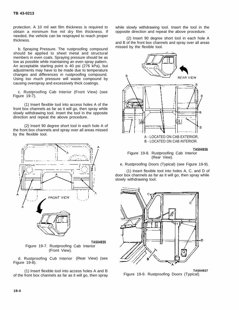
TB 43-0213
protection. A 10 mil wet film thickness is required toobtain a minimum five mil dry film thickness. Ifneeded, the vehicle can be resprayed to reach properthickness.
b. Spraying Pressure. The rustproofing compoundshould be applied to sheet metal and structuralmembers in even coats. Spraying pressure should be aslow as possible while maintaining an even spray pattern.An acceptable starting point is 40 psi (276 kPa), butadjustments may have to be made due to temperaturechanges and differences in rustproofing compound.Using too much pressure will waste compound bycausing overspray and excessively thick coatings.
c. Rustproofing Cab Interior (Front View) (seeFigure 19-7).
(1) Insert flexible tool into access holes A of thefront box channels as far as it will go, then spray whileslowly withdrawing tool. Insert the tool in the oppositedirection and repeat the above procedure.
(2) Insert 90 degree short tool in each hole A ofthe front box channels and spray over all areas missedby the flexible tool.
Figure 19-7. Rustproofing(Front View).
d. Rustproofing Cub InteriorFigure 19-8).
TA504935Cab Interior
(Rear View) (see
(1) Insert flexible tool into access holes A and Bof the front box channels as far as it will go, then spray
while slowly withdrawing tool. Insert the tool in theopposite direction and repeat the above procedure.
(2) Insert 90 degree short tool in each hole Aand B of the front box channels and spray over all areasmissed by the flexible tool.
A - LOCATED ON CAB EXTERIOR,B - LOCATED ON CAB INTERIOR.
TA504936Figure 19-8. Rustproofing Cab Interior
(Rear View).
e. Rustproofing Doors (Typical) (see Figure 19-9).
(1) Insert flexible tool into holes A, C, and D ofdoor box channels as far as it will go, then spray whileslowly withdrawing tool.
TA504937Figure 19-9. Rustproofing Doors (Typical).
19-4
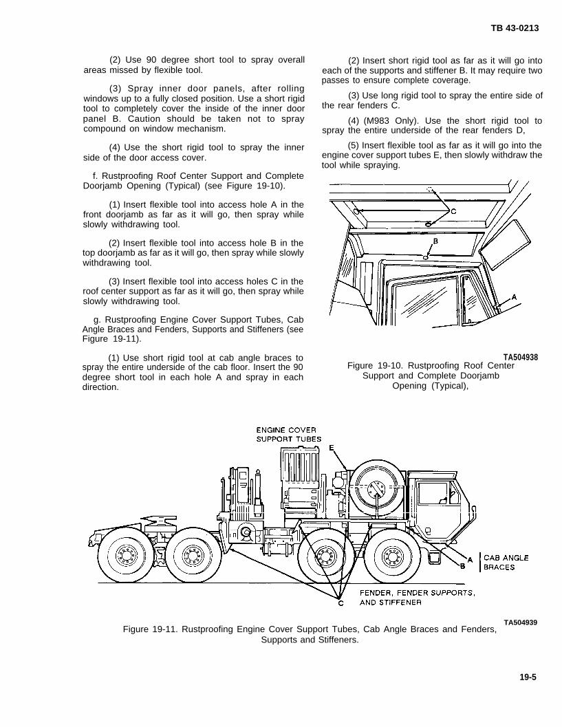
TB 43-0213
(2) Use 90 degree short tool to spray overallareas missed by flexible tool.
(3) Spray inner door panels, after rollingwindows up to a fully closed position. Use a short rigidtool to completely cover the inside of the inner doorpanel B. Caution should be taken not to spraycompound on window mechanism.
(4) Use the short rigid tool to spray the innerside of the door access cover.
f. Rustproofing Roof Center Support and CompleteDoorjamb Opening (Typical) (see Figure 19-10).
(1) Insert flexible tool into access hole A in thefront doorjamb as far as it will go, then spray whileslowly withdrawing tool.
(2) Insert flexible tool into access hole B in thetop doorjamb as far as it will go, then spray while slowlywithdrawing tool.
(3) Insert flexible tool into access holes C in theroof center support as far as it will go, then spray whileslowly withdrawing tool.
g. Rustproofing Engine Cover Support Tubes, CabAngle Braces and Fenders, Supports and Stiffeners (seeFigure 19-11).
(2) Insert short rigid tool as far as it will go intoeach of the supports and stiffener B. It may require twopasses to ensure complete coverage.
(3) Use long rigid tool to spray the entire side ofthe rear fenders C.
(4) (M983 Only). Use the short rigid tool tospray the entire underside of the rear fenders D,
(5) Insert flexible tool as far as it will go into theengine cover support tubes E, then slowly withdraw thetool while spraying.
(1) Use short rigid tool at cab angle braces to TA504938spray the entire underside of the cab floor. Insert the 90 Figure 19-10. Rustproofing Roof Centerdegree short tool in each hole A and spray in each Support and Complete Doorjambdirection. Opening (Typical),
TA504939Figure 19-11. Rustproofing Engine Cover Support Tubes, Cab Angle Braces and Fenders,
Supports and Stiffeners.
19-5
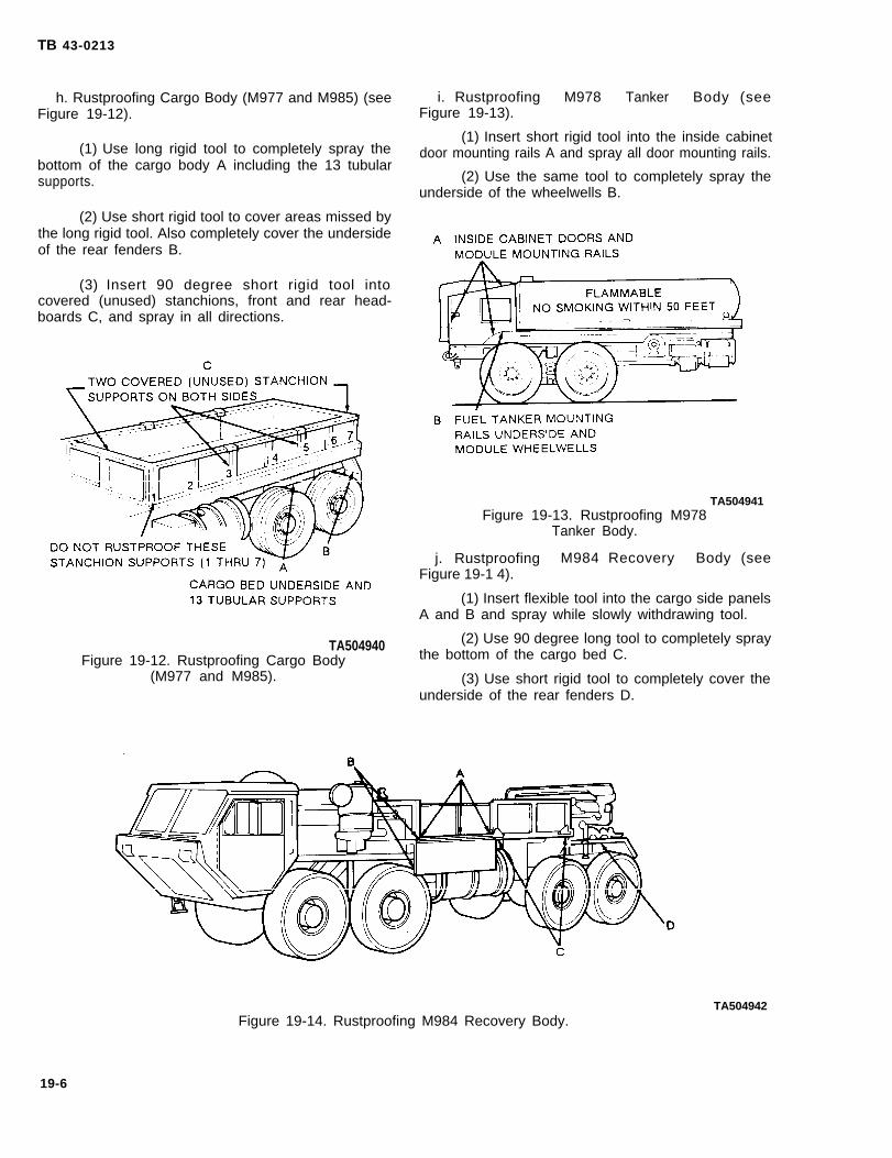
TB 43-0213
h. Rustproofing Cargo Body (M977 and M985) (seeFigure 19-12).
(1) Use long rigid tool to completely spray thebottom of the cargo body A including the 13 tubularsupports.
(2) Use short rigid tool to cover areas missed bythe long rigid tool. Also completely cover the undersideof the rear fenders B.
(3) Insert 90 degree short rigid tool intocovered (unused) stanchions, front and rear head-boards C, and spray in all directions.
TA504940Figure 19-12. Rustproofing Cargo Body
(M977 and M985).
i. Rustproofing M978 Tanker Body (seeFigure 19-13).
(1) Insert short rigid tool into the inside cabinetdoor mounting rails A and spray all door mounting rails.
(2) Use the same tool to completely spray theunderside of the wheelwells B.
TA504941Figure 19-13. Rustproofing M978
Tanker Body.
j. Rustproofing M984 Recovery Body (seeFigure 19-1 4).
(1) Insert flexible tool into the cargo side panelsA and B and spray while slowly withdrawing tool.
(2) Use 90 degree long tool to completely spraythe bottom of the cargo bed C.
(3) Use short rigid tool to completely cover theunderside of the rear fenders D.
TA504942Figure 19-14. Rustproofing M984 Recovery Body.
19-6

TB 43-0213
19-5. Rustproofing Inspection.a. Check the vehicle to ensure that all areas
requiring rustproofing compound have been properlyand completely coated.
(1) Check seams, welds, corners, and boxedareas to ensure that they are adequately coated.
(2) Check wet film thickness with a wet filmthickness gage (see Figure 19-15). A wet film thicknessof 10 mils is required. In areas where a wet filmthickness of 10 mils cannot be obtained or wherethickness cannot be measured, inspect for complete-ness of coverage.
(3) Check all drain holes to ensure that they areopen.
(4) Check all inspection holes and drilledaccess holes to ensure that compound coverage isadequate.
(5) Check vehicle to ensure that no compoundhas been applied to prohibited areas (see CAUTION,paragraph 19-4).
NOTEPlugging of access holes may be delayeduntil after vehicle inspection, if inspectionoccurs immediately after rustproofing. If in-spection is delayed too long, rustproofingcompound may drip from access holes.
b. Plug access holes.
TA504789Figure 19-15. Film Thickness Gage.
19-6. Compound Installation.
Install all components that were removed in para-graph 19-1 (see TM 9-2320-279-10 and TM 9-2320-279-34).
19-7/(19-8 Blank)

M966,M1043,
CHAPTER 20TB 43-0213
M997,M998,M1036, M1038, M1045, M1046, M1025, M1026,M1044, M1037, M1042, M1035 SERIES TRUCKS (HMMWV)
Section I. PRELIMINARY PROCEDURES
20-1. Component Removal.
a. The HMMWV Trucks discussed in this chapterare illustrated in Figure 20-1.
b. Prior to rustproofing, the following componentsmust be removed for access, if equipped. (See TM9-2320-280-20 and TM 9-2320-280-34): (11).
(1). Batteries and Battery Trays(2). Doors(3). Soft Top Canvas (M998, M1038,
M1035 Models Only)(4). Engine Air Cannister(5). Windshield Washer Container
(6). Horn Assembly(7). Floor Mats and Side Pads(8). Seats (Except Driver’s Seat
for all Models)(9). Fuel Tank
(10). Pioneer Tool Rack
(12).
(13).
(14).(15).
(16).
Artic Winterization Kit(Applicable Models)
Weapon Assembly Tray(Applicable Models)
Blanket Straps (M966, M1036,M1045, M1046 Models)
Headlight Dimmer SwitchCargo Shell Door Seal Protectors
(Applicable Models)Headlight Shield Deflectors
Figure 20-1. Typical HMMWV Trucks.
20-1

TB 43-0213
Section Il. DRILLING AND CLEANING PROCEDURES
20-2. Drilling Procedures.
NOTEb. Drilling Underbody (see Figure 20-2).
Unless otherwise indicated, all holes drilledshould be sight drilled and should be 1/2 (1). Drill a 5/16 inch hole in the left andinch (1.3 cm) in diameter. front frame ( A and D). Holes should be drilled 6
inches from last bolt on body mount.Drill holes at approximate locations indicatedby the black dots. (2). Drill a 5/16 inch hole in the left and
right rear frame ( B and C ). Holes should bea. General. Refer to paragraph 3-15 for general drilled 8 inches from transmission crossmemberdrilling instructions. mounting bracket.
Figure 20-2. Drilling Underbody.
20-2
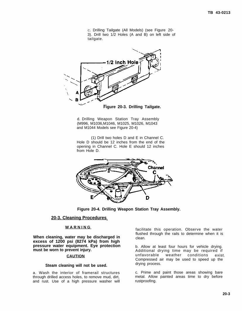
TB 43-0213
C. Drilling Tailgate (All Models) (see Figure 20-3). Drill two 1/2 Holes (A and B) on left side oftailgate.
Figure 20-3. Drilling Tailgate.
d. Drilling Weapon Station Tray Assembly(M996, M1036,M1046, M1025, M1026, M1043and M1044 Models see Figure 20-4)
(1) Drill two holes D and E in Channel C.Hole D should be 12 inches from the end of theopening in Channel C. Hole E should 12 inchesfrom Hole D.
Figure 20-4. Drilling Weapon Station Tray Assembly.
20-3. Cleaning Procedures<
W A R N I N G
When cleaning, water may be discharged inexcess of 1200 psi (8274 kPa) from highpressure water equipment. Eye protectionmust be worn to prevent injury.
CAUTION
Steam cleaning will not be used.
a. Wash the interior of framerail structuresthrough drilled access holes, to remove mud, dirt,and rust. Use of a high pressure washer will
facilitate this operation. Observe the waterflushed through the rails to determine when it isclean.
b. Allow at least four hours for vehicle drying.Additional drying time may be required ifunfavorable weather condit ions exist.Compressed air may be used to speed up thedrying process.
c. Prime and paint those areas showing baremetal. AIlow painted areas time to dry beforerustproofing.
20-3

TB 43-0213
Section Ill. RUSTPROOFING PROCEDURES
20-4. Rustproofing Procedures.
CAUTION
Do not spray any portion of movingcomponents, transmission transfer case,cylinders, pump, valves, prop shaft, exhaustsystem, rubber bump stops, brakedrums,brake backing plates, parking brake linkage,shift linkage, tires, electrical components,engine linkages or air intake systems.Cover all areas with paper and tape asnecessary.
NOTE
There are areas where a 10 mil wet filmthickness cannot be obtained withoutwasting a large amount of compound. Inthose areas, complete coverage of thesurface area is necessary at whateverthickness is obtainable.
a. Dry Film Thickness Requirements. A five mildry film thickness is required for adequaterustproofing protection. A 10 mil wet filmthickness is required to obtain a minimum fivemil dry thickness. If needed, the vehicle can beresprayed to reach the proper thickness.
b. Spraying Pressure. The rustproofing compoundshould be applied to sheet metal and structuralmembers in even coats. Spraying pressure shouldbe as low as possible while maintaining an evenspay pattern. An acceptable starting point is 40psi (kPa), but adjustments may have to be madedue to temperature changes and differences inrustproofing compound. Using too much pressurewill waste the compund by causing overspray andexcessively thick coatings.
c. Rustproofing Frame and Underbody (see Figure20-5 ).
(1) Insert flexible wand tool into existingframerail hole (A) as far as possible toward the
rear of vehicle. Spray in all directions whileslowly withdrawing tool.
(2) Insert flexible wand tool into existingframerail hole (B) as far as possible toward rearof the vehicle and spray in all directions whileslowly withdrawing tool.
(3) Insert flexible wand tool into existingframerail hole (A) as far as possible toward thefront of the vehicle. Spray in all directionswhile slowly withdrawing tool.
(4) insert flexible wand tool into existingframerail hole (C) as far as possible toward thefront of the vehicle. Spray in all directions whileslowly withdrawing tool.
(5) Insert flexible wand tool in exisitingframerail hole (D) as far as possible toward thefront of the vehicle and spray in all directions while slowly withdrawing flexible wand tool.
(6) Insert flexible wand tool into existingframerail hole (E) as far as possible toward therear of the vehicle. Spray in all directionswhile slowly withdrawing tool.
(7) Insert flexible wand tool into existingframerail hole (F) as far as possible toward therear of the vehicle . Spray in all directionswhile slowly withdrawing tool.
(8) Insert flexible wand tool into existingframerail hole (E) as far as possible toward thefront of the vehicle. Spray in all directionswhile slowly withdrawing tool.
(9) Insert flexible wand tool into existingframerail hole (G) as far as possible toward thefront of the vehicle. Spray in all directionswhile slowly withdrawing tool.
(10) Insert flexible wand tool into exisingframerail hole (H) as far as possible toward thefront of the vehicle. Spray in all directionswhile slowly withdrawing tool.
(11) Use flexible tool to completely cover allexterior underbody surfaces.
20-4
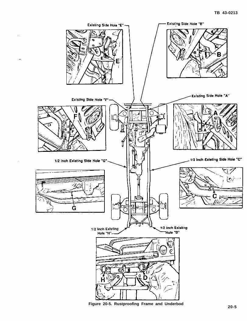
TB 43-0213
Figure 20-5. Rustproofing Frame and Underbod20-5

TB 43-0213
d. Body Panel Side Rails (All Models seeFigure 20-6).
(1) Insert flexible wand tool as far aspossible toward rear of the vehicle at points (A)on left and right of vehicle. Spray in alldirections while slowly withdrawing tool.
(2) Insert flexible wand tool as far aspossible toward front of vehicle at points (B) onleft and right of vehicle. Spray in all directionswhile slowly withdrawing tool.
Figure 20-6. Body Panel Side Rails.
Figure 20-7.
f. Rustproofing8 ).
Rustproofing Floorboards andBattery Boxes.
Tailgate (All Models; see Figure 20-
(1) Insert rigid wand assembly tool intohole A then B as far as possible and spray in alldirections. Using directional handle, rotate (in acircular manner) while slowly withdrawing tool.
NOTE
Leave tailgate in horizontal position for 24hours.
e. Rustproofing Floorboards and Battery Boxes (All Models except Ambulances; see Figure 20-7).
(1) Using flexible wand tool, spray allfloorboards including stowage and battery boxtray areas.
Figure 20-8. Rustproofing Tailgate.
20-6

TB 43-0213
g. Rustproofing Cargo Shell Door (M996,M1036,M1046, M1025, M1026, M1043 andM1044 Models see Figure 20-9).
NOTE
Cover Four Latch Mechanisms BeforeRustproofing
(1) Insert flexible tool and rustproofthrough openings A, B, C, D, E., F, and G.. Sprayin all directions while slowly withdrawing tool.
(2) Insert flexible tool into two channels
behind door insulation. Spray in all directionswhile slowly withdrawing tool.
(3) Spray Cargo Shell Door seal protectors,
(2) Insert flexible wand tool into Support Tubeas far as possible at point (B). Spray in alld i rect ions whi le s lowly wi thdrawing tool .(Repeat on Passenger’s Side).
Figure 20-10. Rustproofing Roof Seams, Channelsand Support Tubes (M996, M1036. M1046, M1025,M1026, M1043 and M1044 Models).
i. Rustproofing Armament Pintle (M996, M1036,M1046, M1025, M1026, M1043 and M1044 Modelssee Figure 20-11).
(1) Using flexible tool, spray in three holes A.Latch Mechanism
Figure 20-9. Rustproofing Cargo Shell Dooi(M996, M1046, M1036, M1025,
M1026, M1043 and M1044 Models).
h. Rustproofing Roof Seams, Channels and SupportTubes (M996, M1036, M1046, M1025, M1026M1043 and M1044 Models see Figure 20-10).
CAUTION
Tape Openings in Channels Before ApplyingRustproofing Compound
Figure 20-11. Rustproofing Armament Pintle (M996,M1036, M1046, M1025, M1026, M1043 and M1044Models). .(1) Insert flexible tool into hole A and spray in
all directions.
20-7

TB 43-0213
j Rustproofing Weapon Station Tray Assembly(Topside) (M996, M1036, M1046, M1025, M1026,M1043 and M1044 Models see Figure 20-12).
(1). Insert flexible tool into holes A, B, C, Dand E. Spray in all directions while slowlywithdrawing tool,
Figure 20-12. Rustproofing Weapon Station TrayAssembly (Topside) (M996, M1036, M1046, M1025,M1026, M1043, and M1044 ).
k. Rustproofing Cargo Shell Assemblies (M996,M1036,M1046, M1025, M1026, M1043 and M1044Models see Figure 20-13).
NOTECargo Shell Door Should Be Opened
(1) Using flexible tool, coat back, side pannelsand all seams of Cargo Shell MountingComponents.
Figure 20-13. flustprooflng Cargo Shell Assemblies(M996, M1036, M1046, M1025, M1026, M1043, andM1044 ).
l. Rustproofing Headlight Shield Deflectors seeFigure 20-14).
(1). Spray both sides of Headlight ShieldDeflector.
Figure 20-14. Rustproofing Headlight Shield Deflectors
20-5. Rustproofing Inspection.
a. Check the vehicle to ensure that all areasrequiring rustproofing compound have beenproperly and completely covered.
(1) Check seams, welds, corners and boxed areas to ensure they are adequatelycovered.
(2) Check wet film thickness with a wetfilm thickness gage (see Figure 20-15). A wetfilm thickness of 10 roils is required. In areawhere a wet film thickness cannot be obtained orwhere wet thickness cannot be measured, inspectfor completeness of coverage.
Figure 20-15. Wet Film Thickness Gage.
(3) Check all drain holes to ensure that they are open.
(4) Check all inspection holes anddrilled access holes to ensure that compoundcoverage is adequate.
(5) Check vehicle to ensure that nocompound has been applied toprohibited areas (see CAUTION, paragraph 20-
4).
NOTE
Plugging of access holes may be delayeduntil after vehicle inspection, if inspectionoccurs immediately after rustproofing. Ifinspection is delayed too long, rustproofingcompound may drip from access holes.
b. Plug access holes.
20-6. Component Installation.
Install all components that were removedin paragraph 20-1 (see TM 9-2320-280-20 and TM9-2320-280-34).
20-8
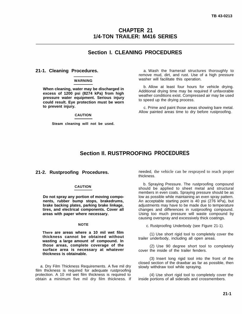
TB 43-0213
CHAPTER 211/4-TON TRAILER: M416 SERIES
Section I. CLEANING PROCEDURES
21-1. Cleaning Procedures.
WARNING
a. Wash the framerail structures thoroughly toremove mud, dirt, and rust. Use of a high pressurewasher will facilitate this operation.
When cleaning, water may be discharged inexcess of 1200 psi (8274 kPa) from highpressure water equipment. Serious injurycould result. Eye protection must be wornto prevent injury.
CAUTION
Steam cleaning will not be used.
b. Allow at least four hours for vehicle drying.Additional drying time may be required if unfavorableweather conditions exist. Compressed air may be usedto speed up the drying process.
c. Prime and paint those areas showing bare metal.Allow painted areas time to dry before rustproofing.
Section Il. RUSTPROOFING
21-2. Rustproofing Procedures.
CAUTION
Do not spray any portion of moving compo-nents, rubber bump stops, brakedrums,brake backing plates, parking brake linkage,tires, and electrical components. Cover allareas with paper where necessary.
NOTE
There are areas where a 10 mil wet filmthickness cannot be obtained withoutwasting a large amount of compound. Inthose areas, complete coverage of thesurface area is necessary at whateverthickness is obtainable.
a. Dry Film Thickness Requirements. A five mil dryfilm thickness is required for adequate rustproofingprotection. A 10 mil wet film thickness is required toobtain a minimum five mil dry film thickness. If
needed,
PROCEDURES
the vehicle can be resprayed to reach properthickness.
b. Spraying Pressure. The rustproofing compoundshould be applied to sheet metal and structuralmembers in even coats. Spraying pressure should be aslow as possible while maintaining an even spray pattern.An acceptable starting point is 40 psi (276 kPa), butadjustments may have to be made due to temperaturechanges and differences in rustproofing compound.Using too much pressure will waste compound bycausing overspray and excessively thick coatings.
c. Rustproofing Underbody (see Figure 21-1).
(1) Use short rigid tool to completely cover thetrailer underbody, including all open areas.
(2) Use 90 degree short tool to completelycover the inside of the trailer fenders.
(3) Insert long rigid tool into the front of theclosed section of the drawbar as far as possible, thenslowly withdraw tool while spraying.
(4) Use short rigid tool to completely cover theinside portions of all siderails and crossmembers.
21-1

TB 43-0213
21-3.
Figure 21-1.
Rustproofing Inspection.
TA504943Rustproofing Underbody.
Check the vehicle to ensure that all areas requiringrustproofing compound have been properly andcompletely coated.
a. Check seams, welds, corners, and boxed areas toensure that they are adequately coated.
b. Check wet film thickness with a wet filmthickness gage (see Figure 21-2). A wet film thicknessof 10 roils is required. In areas where a wet filmthickness of 10 roils cannot be obtained or wherethickness cannot be measured, inspect for complete-ness of coverage.
c. Check vehicle to ensure that no compound hasbeen applied to prohibited areas (see CAUTION,paragraph 21-2 ).
TA504789Figure 21-2. Film Thickness Gage.
21-2

TB 43-0213
CHAPTER 223/4-TON TRAILER: Ml101 SERIES
Section I. DRILLING AND CLEANING PROCEDURES
22-1. Drilling Procedures. a. General. Referdrilling instructions.
NOTE
to paragraph 3-15
(see Figure 22-2).
for general
Drill threeUnless otherwise indicated, all holes b. Drilling Frame
should be sight drilled and should be holes A in center framerail. The first hole is drilled in a
1/2 inch (1.3 cm) in diameter. centered position. The other two holes are drilled6 inches (15.2 cm) from the outside of the framerails.
The M101 Series Trailer discussed in thischapter is illustrated in Figure 22-1.
TA504944Figure 22-1. M101 3/4-Ton Trailer.
TA504945Figure 22-2. Drilling Frame.
22-1
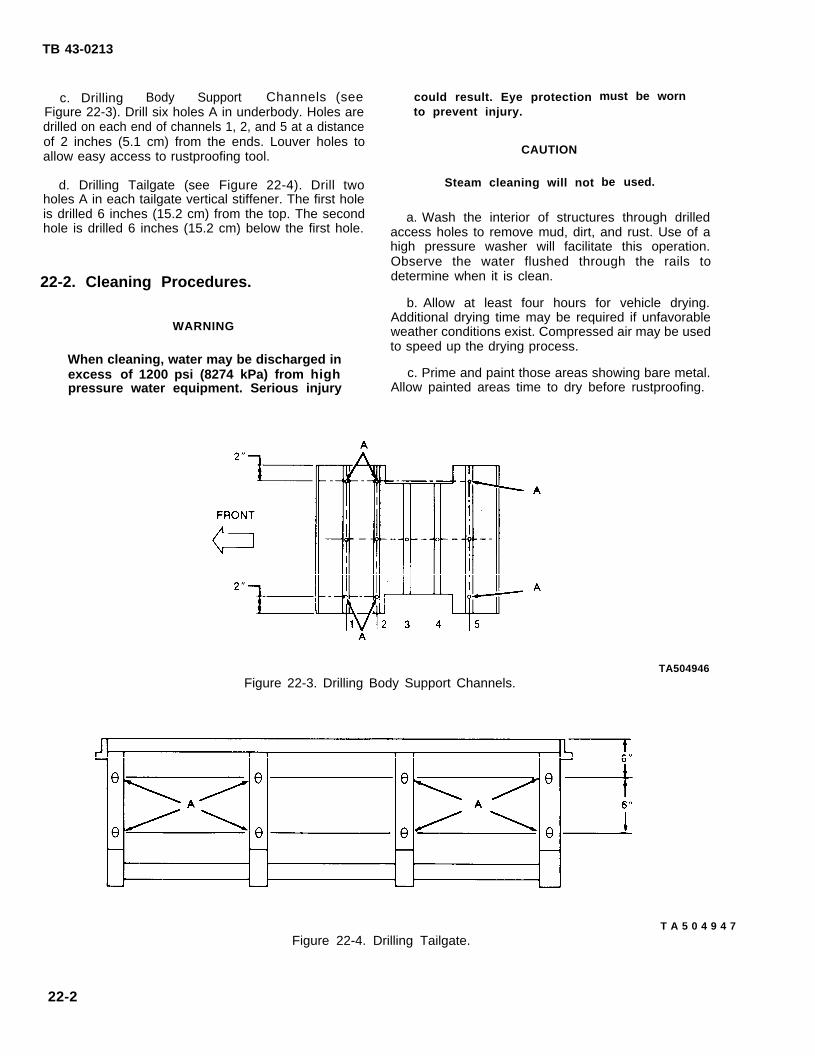
TB 43-0213
c. Drilling Body Support Channels (seeFigure 22-3). Drill six holes A in underbody. Holes aredrilled on each end of channels 1, 2, and 5 at a distanceof 2 inches (5.1 cm) from the ends. Louver holes toallow easy access to rustproofing tool.
d. Drilling Tailgate (see Figure 22-4). Drill twoholes A in each tailgate vertical stiffener. The first holeis drilled 6 inches (15.2 cm) from the top. The secondhole is drilled 6 inches (15.2 cm) below the first hole.
22-2. Cleaning Procedures.
WARNING
When cleaning, water may be discharged inexcess of 1200 psi (8274 kPa) from highpressure water equipment. Serious injury
could result. Eye protectionto prevent injury.
CAUTION
Steam cleaning will not
must be worn
be used.
a. Wash the interior of structures through drilledaccess holes to remove mud, dirt, and rust. Use of ahigh pressure washer will facilitate this operation.Observe the water flushed through the rails todetermine when it is clean.
b. Allow at least four hours for vehicle drying.Additional drying time may be required if unfavorableweather conditions exist. Compressed air may be usedto speed up the drying process.
c. Prime and paint those areas showing bare metal.Allow painted areas time to dry before rustproofing.
Figure 22-3. Drilling Body Support Channels.TA504946
T A 5 0 4 9 4 7 Figure 22-4. Drilling Tailgate.
22-2
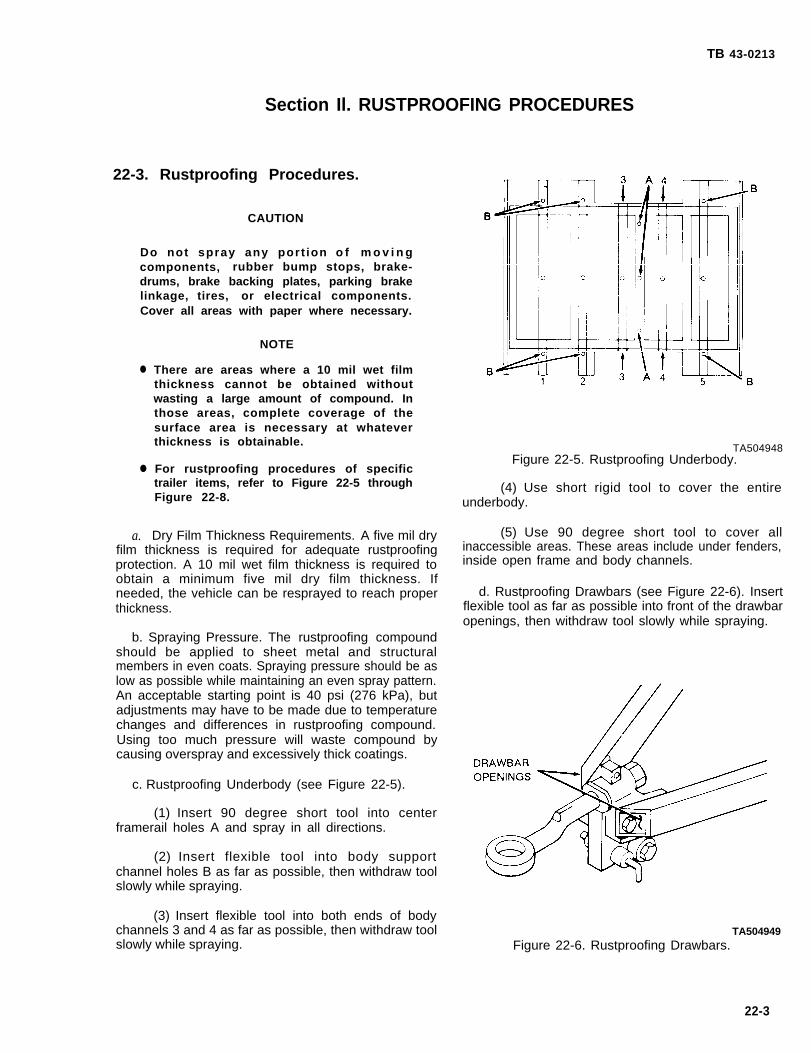
TB 43-0213
Section Il. RUSTPROOFING PROCEDURES
22-3. Rustproofing Procedures.
CAUTION
Do not spray any port ion o f m o v i n gcomponents, rubber bump stops, brake-drums, brake backing plates, parking brakelinkage, tires, or electrical components.Cover all areas with paper where necessary.
●
●
a.
NOTE
There are areas where a 10 mil wet filmthickness cannot be obtained withoutwasting a large amount of compound. Inthose areas, complete coverage of thesurface area is necessary at whateverthickness is obtainable.
For rustproofing procedures of specifictrailer items, refer to Figure 22-5 throughFigure 22-8.
Dry Film Thickness Requirements. A five mil dryfilm thickness is required for adequate rustproofingprotection. A 10 mil wet film thickness is required toobtain a minimum five mil dry film thickness. Ifneeded, the vehicle can be resprayed to reach properthickness.
b. Spraying Pressure. The rustproofing compoundshould be applied to sheet metal and structuralmembers in even coats. Spraying pressure should be aslow as possible while maintaining an even spray pattern.An acceptable starting point is 40 psi (276 kPa), butadjustments may have to be made due to temperaturechanges and differences in rustproofing compound.Using too much pressure will waste compound bycausing overspray and excessively thick coatings.
c. Rustproofing Underbody (see Figure 22-5).
(1) Insert 90 degree short tool into centerframerail holes A and spray in all directions.
(2) Insert flexible tool into body supportchannel holes B as far as possible, then withdraw toolslowly while spraying.
(3) Insert flexible tool into both ends of bodychannels 3 and 4 as far as possible, then withdraw toolslowly while spraying.
TA504948Figure 22-5. Rustproofing Underbody.
(4) Use short rigid tool to cover the entireunderbody.
(5) Use 90 degree short tool to cover allinaccessible areas. These areas include under fenders,inside open frame and body channels.
d. Rustproofing Drawbars (see Figure 22-6). Insertflexible tool as far as possible into front of the drawbaropenings, then withdraw tool slowly while spraying.
TA504949Figure 22-6. Rustproofing Drawbars.
22-3

TB 43-0213
e. Rustproofing Tailgate (see Figure 22-7).
(1) Insert 90 degree short tool into verticalstiffener holes A and spray in all directions. Plug holes.
(2) Insert flexible tool into hole B on the rightand left side of the bottom horizontal stiffener as far aspossible, then withdraw tool slowly while spraying.
(3) Use the 90 degree short tool to completelycover the underside of the upper horizontal stiffener.
f. Rustproofing Rubrails and Stake Pockets (seeFigure 22-8).
(1) Insert long rigid tool into the stake pockets
as far asspraying.
(2)cover the
possible, then withdraw tool slowly while
Use 90 degree short tool to completelyundersides of the rubrails.
22-4. Rustproofing Inspection.
a. Check the vehicle to ensure that all areasrequiring rustproofing compound have been properlyand completely coated.
(1) Check seams,areas to ensure that they
welds, corners, and boxedare adequately coated.
TA504950Figure 22-7. Rustproofing Tailgate.
Figure 22-8. Rustproofing Rubrails and Stake Pockets.TA504951
22-4

TB 43-0213
(2) Check wet film thickness with a wet filmthickness gage (see Figure 22-9). A wet film thicknessof 10 mils is required. In areas where a wet filmthickness of 10 mils cannot be obtained or wherethickness cannot be measured, inspect for complete-ness of coverage.
(3) Check all drain holes to ensure that they areopen.
(4) Check all inspection holes and drilledaccess holes to ensure that compound coverage isadequate.
(5) Check vehicle to ensure that no compoundhas been applied to prohibited areas (see CAUTION,paragraph 22-3).
NOTEPlugging of access holes may be delayeduntil after vehicle inspection, if inspectionoccurs immediately after rustproofing. If in-spection is delayed too long, rustproofingcompound may drip from access holes.
b. Plug access holes.
TA504789Figure 22-9. Film Thickness Gage.
22-5/(22-6 Blank)

TB 43-0213
CHAPTER 231 1/2-TON CARGO TRAILER: M105 SERIES
Section I. DRILLING AND CLEANING PROCEDURES
23-1. Drilling Procedures.
NOTE
Unless otherwise indicated, all holesshould be sight drilled and should be1/2 inch (1.3 cm) in diameter.
The M105 Series Cargo Trailer discussedin this chapter is illustrated inFigure 22-1.
a. General. Refer to paragraph 3-15 for generaldrilling instructions.
Figure 23-1. M105 Cargo Trailer. TA504952
b, Drilling Underbody (see Figure 23-2). Drill twoholes A in each body support channels 1, 2, 3, 4, 9, 10,and 11. The holes are drilled 6 inches (15.2 cm) fromthe ends of the channels. Louver holes to allow easy
entry of tools.
TA504953Figure 23-2. Underbody.
c. Drilling Tailgate (see Figure 23-3). Drill sevenholes in tailgate:
(1) Two holes A are drilled at each end of theupper horizontal stiffener.
(2) Two holes B are drilled at each end of thecenter horizontal stiffener.
(3) Three holes C are drilled in the bottom ofeach section of the hinge rod channel.
Figure 23-3. Drilling Tailgate.TA504954
23-1160-363 0- 94- 7

TB 43-0213
23-2. Cleaning Procedures.
WARNING
When cleaning, water may be discharged inexcess of 1200 psi (8274 kPa) from highpressure water equipment. Serious injurycould resuil. Eye protection must be wornto prevent injury.
CAUTION
Steam cleaning will not be used.
a. Wash the interior of structures through drilledaccess holes to remove mud, dirt, and rust. Use of ahigh pressure washer will facilitate this operation.Observe the water flushed through the rails todetermine when it is clean.
b. Allow at least four hours for vehicle drying.Additional drying time may be required if unfavorableweather conditions exist. Compressed air may be usedto speed up the drying process.
c. Prime and paint those areas showing bare metal.Allow painted areas time to dry before rustproofing.
Section II. RUSTPROOFING PROCEDURES
23-3. Rustproofing Procedures.
CAUTION
Do not spray any portion of movingcomponents, rubber bump stops, brake-drums, brake backing plates, parking brakelinkage, tires, or electrical components.Cover all areas with paper where necessary.
●
●
a.
NOTE
There are areas where a 10 mil wet filmthickness cannot be obtained withoutwasting a large amount of compound. Inthose areas, complete coverage of thesurface area is necessary at whateverthickness is obtainable.
For rustproofing procedures of specificcargo trailer items, refer to Figure 23-2through Figure 23-5.
Dry Film Thickness Requirements. A five mil dryfilm thickness is required for adequate rustproofingprotection. A 10 mil wet film thickness is required toobtain a minimum five mil dry film thickness. Ifneeded, the vehicle can be resprayed to reach properthickness.
b. Spraying Pressure. The rustproofing compoundshould be applied to sheet metal and structuralmembers in even coats. Spraying pressure should be as
low as possible while maintaining an even spray pattern.An acceptable starting point is 40 psi (276 kPa), butadjustments may have to be made due to temperaturechanges and differences in rustproofing compound.Using too much pressure will waste compound bycausing overspray and excessively thick coatings.
c. Rustproofing Underbody (see Figure 23-2).
(1) Insert flexible tool as far as possible into allbody support channel holes A. Spray while slowlywithdrawing the tool.
(2) Insert flexible tool into the ends of bodysupport channels 5, 6, 7, and 8 as far as possible, thenslowly withdraw tool while spraying.
(3) Use short rigid tool to completely cover theunderbody.
(4) Use the 90 degree short tool with thecone-spray tip to cover all inaccessible areas. Theseareas include inside of frame channels and fenders.
d. Rustproofing Tailgate (see Figure 23-4)
(1) Insert long rigid tool into holes A and B ofthe tailgate horizontal stiffeners as far as possible, thenslowly withdraw tool while spraying.
(2) Insert 90 degree short tool into holes A andB and spray in all directions.
(3) Insert 90 degree short tool into holes C andspray in all directions.
23-2

TB 43-0213
e. Rustproofing Rubrails and Stake Pockets (see as far as possible, then withdraw tool slowly whileFigure 23-5).
(1) Insert
spraying. -
(2) Use 90 degree short toollong rigid tool into the stake pockets cover the undersides of the rubrails.
to completely
TA504955Figure 23-4. Rustproofing Tailgate.
Figure 23-5. Rustproofing Rubrails and Stake Pockets.TA504956
23-3

TB 43-0213
23-4. Rustproofing Inspection.a. Check the vehicle to ensure that all areas
requiring rustproofing compound have been properlyand completely coated.
(1) Check seams, welds, corners, and boxedareas to ensure that they are adequately coated.
(2) Check wet film thickness with a wet filmthickness gage (see Figure 23-6). A wet film thicknessof 10 nils is required. In areas where a wet filmthickness of 10 mils cannot be obtained or wherethickness cannot be measured, inspect for complete-ness of coverage.
(3) Check all drain holes to ensure that they areopen.
(4) Check all inspection holes and drilledaccess holes to ensure that compound coverage isadequate.
(5) Check vehicle to ensure that no compoundhas been applied to prohibited areas (see CAUTION,paragraph 23-3).
NOTEPlugging of access holes may be delayeduntil after vehicle inspection, if inspectionoccurs immediatelyinspection is delayedcompound may drip
b. Plug access holes.
after rustproofing. Iftoo long, rustproofingfrom access holes.
TA504789Figure 23-6. Film Thickness Gage.
23-4

TB 43-0213
APPENDIX AREFERENCES
A-1 ● Scope.
a, This appendix lists all forms, technical manuals, field manuals, technical bulletins, policy statements,regulations, and specifications referenced in this technical bulletin.
b. Paragraph A-5 provides a list of related specifications not directly cited in the text. This additional list isprovided for the information and record of facilities procuring rustproofing services or establishing a rustproofingoperation.
c. This appendix excludes specific vehicle TM references found within the individual rustproofing procedures.Such references are for purposes of component removal and installation only. As such, they are not specificallyrelated to the subject matter of this technical bulletin.
A-2.
A-3.
A-4.
A-5.
Forms.
Product Quality DeficiencyRecommended Changes toRecommended Changes to
Report . . . . . . . . . . . . . . . . . . . . . . . . . . . . . . . . . . . . . . . . . . . . . . . .. SF 368Equipment Technical Publications . . . . . . . . . . . . . . . . . . . DA Form 2028-2Publications and Blank Forms. . . . . . . . . . . . . . . . . . . . . .. DA Form 2028
Related Manuals/Technical Bulletins.
Color, Marking, and Camouflage Painting of Military Vehicles,Construction Equipment and Materials Handling Equipment . . . . . . . . . . . . . . . . . . . . . . TB 43-0209.
First Aid for Soldiers . . . . . . . . . . . . . . . . . . . . . . . . . . . . . . . . . . . . . . . . . . . . . . . . . . . . . . . . ..FM 21-11Materials Used for Cleaning, Preserving, Abrading, and Cementing
Ordinance Materiel and Related Material Including Chemicals . . . . . . . . . . . . . . . . . . . . . . TM 9-247Metal Body Repair and Related Operations . . . . . . . . . . . . . . . . . . . . . . . . . . . . . . . . . . . . . . . ..FM 43-2Operator’s Manual for Welding Theory and Application . . . . . . . . . . . . . . . . . . . . . . . . . . . . . TM 9-237Painting Instructions for Field Use . . . . . . . . . . . . . . . . . . . . . . . . . . . . . . . . . . . . . . . . . . . .. TM 43-0139
Policies/Specifications.
Corrosion Prevention and Control (CPC) . . . . . . . . . . . . . . . . . . . . . . . . . . . . . . . . . . . . . .. AR 750-XXXMateriel Deterioration Prevention and Control . . . . . . . . . . . . . . . . . . . . . . . . . . . . . . . . AMC-R-702-24
Related Specifications.
Rust Arresting Coating (for Treatment of Rusted Metal) . . . . . . . . . . . . . . . . . . . . . . . . . MIL-R-10036ERustproofing of Commercial (Non-Tactical) Vehicles . . . . . . . . . . . . . . . . . . . . . . . . . . . FED-STD-297D
A-1/(A-2 Blank)
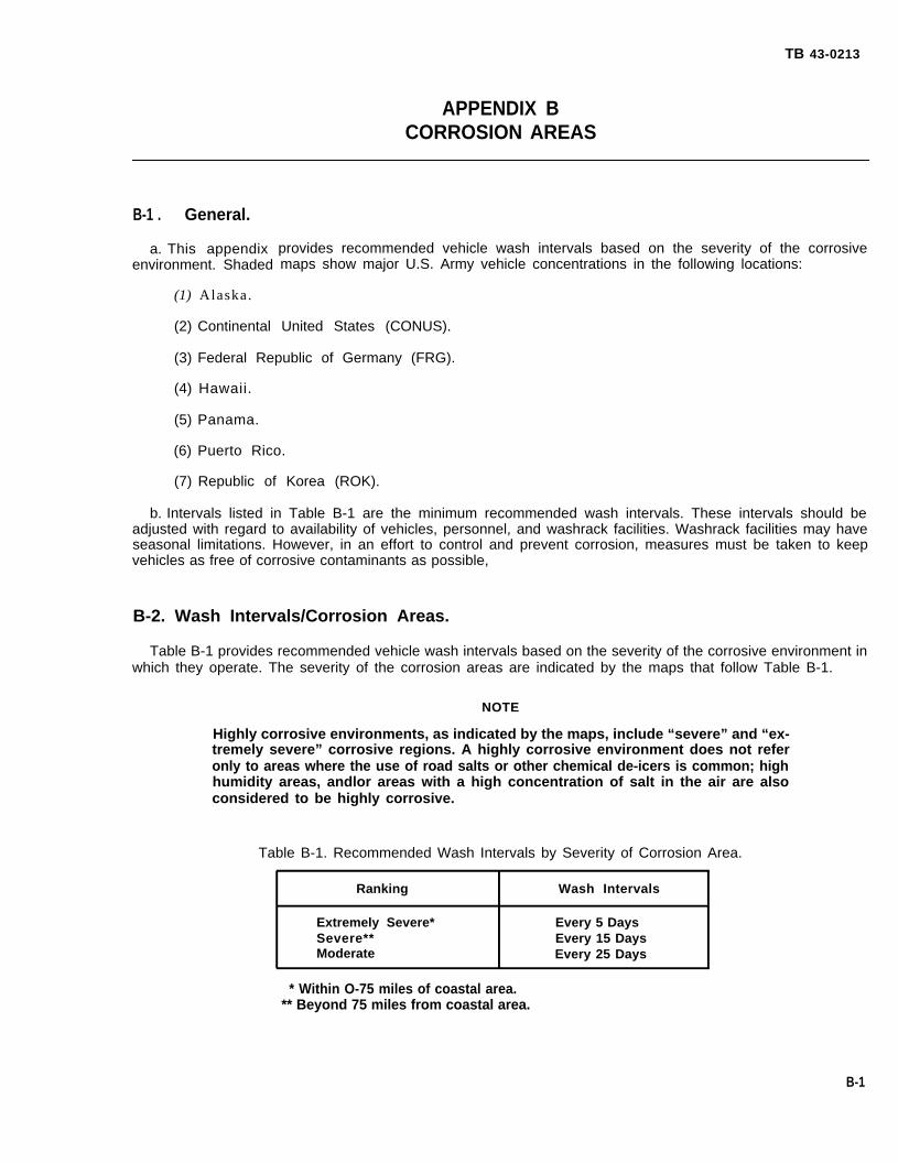
TB 43-0213
APPENDIX BCORROSION AREAS
B-1 . General.
a. This appendixenvironment. Shaded
(1) Alaska.
provides recommended vehicle wash intervals based on the severity of the corrosivemaps show major U.S. Army vehicle concentrations in the following locations:
(2) Continental United States (CONUS).
(3) Federal Republic of Germany (FRG).
(4) Hawaii.
(5) Panama.
(6) Puerto Rico.
(7) Republic of Korea (ROK).
b. Intervals listed in Table B-1 are the minimum recommended wash intervals. These intervals should beadjusted with regard to availability of vehicles, personnel, and washrack facilities. Washrack facilities may haveseasonal limitations. However, in an effort to control and prevent corrosion, measures must be taken to keepvehicles as free of corrosive contaminants as possible,
B-2. Wash Intervals/Corrosion Areas.
Table B-1 provides recommended vehicle wash intervals based on the severity of the corrosive environment inwhich they operate. The severity of the corrosion areas are indicated by the maps that follow Table B-1.
NOTE
Highly corrosive environments, as indicated by the maps, include “severe” and “ex-tremely severe” corrosive regions. A highly corrosive environment does not referonly to areas where the use of road salts or other chemical de-icers is common; highhumidity areas, andlor areas with a high concentration of salt in the air are alsoconsidered to be highly corrosive.
Table B-1. Recommended Wash Intervals by Severity of Corrosion Area.
Ranking Wash Intervals
Extremely Severe* Every 5 DaysSevere** Every 15 DaysModerate Every 25 Days
* Within O-75 miles of coastal area.** Beyond 75 miles from coastal area.
B-1
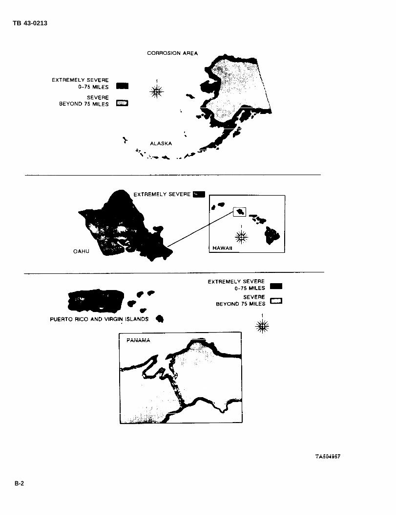
TB 43-0213
B-2

TB 43-0213
B-3/(B-4 Blank)
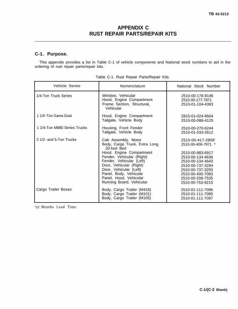
TB 43-0213
APPENDIX CRUST REPAIR PARTS/REPAIR KITS
C-1. Purpose.
This appendix provides a list in Table C-1 of vehicle components and National stock numbers to aid in theordering of rust repair parts/repair kits.
.
Table C-1. Rust Repair Parts/Repair Kits.
Vehicle Series Nomenclature National Stock Number
1/4-Ton Truck Series Window, Vehicular 2510-00-176-9146Hood, Engine Compartment 2510-00-177-7871Frame Section, Structural, 2510-01-104-4383
Vehicular
1 1/4~Ton Gama Goat Hood, Engine Compartment 2815-01-024-9564Tailgate, Vehicle Body 2510-00-088-4125
1 1/4-Ton M880 Series Trucks Housing, Front Fender 2510-00-270-6244. Tailgate, Vehicle Body 2510-01-033-2612
2 1/2- and 5-Ton Trucks Cab Assembly, Motor 2510-00-417-2808’Body, Cargo Truck, Extra Long 2510-00-409-7971 *
20-foot BedHood, Engine Compartment 2510-00-983-6917Fender, Vehicular (Right) 2510-00-134-4636Fender, Vehicular (Left) 2510-00-134-4643Door, Vehicular (Right) 2510-00-737-3294Door, Vehicular (Left) 2510-00-737-3293Panel, Body, Vehicular 2510-00-400-7083Panel, Hood, Vehicular 2510-00-208-7535Running Board, Vehicular 2510-00-753-9215
Cargo Trailer Boxes Body, Cargo Trailer (M416) 2510-01-111-7096Body, Cargo Trailer (M101) 2510-01-111-7095Body, Cargo Trailer (M105) 2510-01-111-7097
*12 Months Lead Time.
C-1/(C-2 Blank)
TB 43-0213
APPENDIX DRUST REPAIR AND BODY REPLACEMENT INSTRUCTIONS FOR
M151 , M718, AND M825 SERIES TRUCKS
Section I. FABRICATION OF TURNING FIXTUREAND TURNING VEHICLE OVER
D-1. Construction of
a. Front Turning Fixturedescribed in Figure D-2.
b. Rear Turning Fixturedescribed in Figure D-3.
D-2.
a.
b.body
c.
Turning Vehicle
Drain fuel tank, then
Front and Rear Turning Fixtures.
(see Figure D-1). Construct a front turning fixture in accordance with requirements
(see Figure D-l). Construct a rear turning fixture in accordance with requirements
Over.
run engine until all fuel in the carburetor and fuel lines has been expended.
Remove fuel tank, windshield,(see TM 9-2320-218-20-1-1).
Drain engine oil, transmissionTap vent hole in master cylinder.218-20-1-2).
d.
e.
f .
g.of 36
h.
When applicable, remove the
batteries, air filter, spare tire, and soft top. Secure the bow assembly to the
fluid, windshield washer fluid, and differential fluid from both differentials.Drain the steering gear box on M151 series vehicles (see TM 9-2320 -
following:
(1) Extension and litter racks.
(2) Radio mounts and antennas.
(3) Machine gun mount.
(4) Crew seats (M151A1C and M825).
Remove front lifting eyes. Use existing hardware to install front turning fixture (see Figure D-1).
Remove pintle. Use existing hardware to install rear turning fixture (see Figure D-1).
Attach chain falls to lifting eyes of front and rear turning fixtures (see Figure D-1). Raise vehicle a minimuminches (91.4 cm) measured from floor to bottom of front and rear tires.
Remove retaining bolts from turning fixtures. Position four people at each corner of vehicle and rotate vehicle180 degrees, bottom side up. Replace retaining bolts in turning fixtures.
i. Lower vehicle onto two support stands, The front support stand should be approximately 14 inches (35.6cm) high by 40 inches (101.6 cm) long. The rear support stand should be approximately 20 inches (50.8 cm) highby 56 inches (142.2 cm) long (see Figure D-4).
D-1

TB 43-0213
TA504959
D-2
Figure D-1. Fabricated Turning Fixtures.

TB 43-0213
Figure D-2. Construction of Front Turning Fixture.
D-3

TB 43-0213
Figure D-3. Construction of Rear Turning Fixture.
D-4

TB 43-0213
Figure D-4. Vehicle Lowered to Stand.
Section Il. REPAIRING RUST DAMAGE
D-3. Materiel Requirements.
Table D-1 lists the underbody caps that are provided with the underbody corrosion repair kit, NSN 2510-01-104-4383 (see Figure D-5).
Table D-1. Underbody Corrosion Repair Kit.
Item Part No. Quantity Description
1 12275196 1 CAP - SILL REAR CROSS CTR
2 12275197-1 1 CAP ASSY - X/MBR REAR SUSP SUPT FRT-LH
3 12275197-2 1 CAP ASSY - X/MBR REAR SUSP SUPT FRT-RH
4 12302501 1 CAP - X/MBR ENGINE REAR SUPT-LH
5 12302500 1 CAP - X/MBR ENGINE REAR SUPT-RH
6 12275199 2 CAP - RAIL OUTER CENTER
7 12275198 1 CAP - X/MBR ENGINE REAR SUPT CENTER
8 12275194-1 1 EXT CAP X/MBR ENGINE REAR SUPT-LH
9 12275194-2 1 EXT CAP X/MBR ENGINE REAR SUPT-RH
10 12275193 2 EXT - RAIL OUTER CENTER TO CAP X/MBR ENGINE REAR SUPT
11 12275195 2 E)(T - RAIL OUTER CENTER TO CAP X/MBR REAR SUSP SUPT FRT
D-5

TB 43-0213
Figure D-5. Caps (M151 Underbody Repair Kit).
D-4. Underbody Component Removal.
a. Remove rear drive shaft. Then remove rear exhaust system from muffler and underbody (see TM 9-2320-218-20-1-1).
b. Remove two rear control arm bolts (see Figure D-6).
Figure D-6. Removing Control Arm Bolts.
D-6

TB 43-0213
D-5. Inspection of Underbody.
NOTE
. Corrosion damage in areas marked X is repairable if caps supplied for those areascover rusted-out sections, and plug weld holes are
. To repair rust damaged vehicles in areas marked X,#B1230250-6 (M151A2 only).
a. Inspect underside of vehicle for corrosiondamage (see Figure D-7). Pay special attention to areasmarked X, in which corrosion commonly occurs. Theseareas are critical, high-load areas. Excessive corrosiondamage in these areas (corrosion which has penetratedentirely through metal) will render a vehicle nonrepair-able.
NOTE
Body patches can be welded to body to ac-complish repair. The resultant patch must,however, be as strong or stronger than theoriginal material it is replacing,
b. Probe underside of vehicle with a punch andhammer, Locate badly corroded areas, and determineif vehicle meets required criteria for repair.
located over solid metal.
order body replacement kit
Figure D-7. Underbody.
D-7
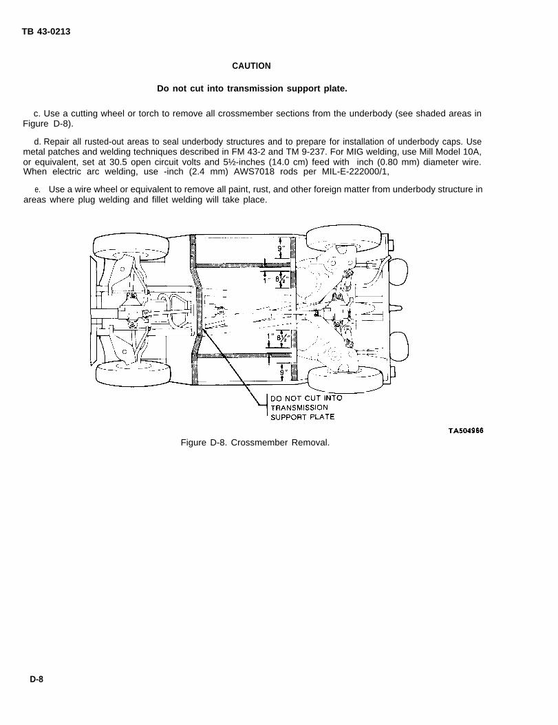
TB 43-0213
CAUTION
Do not cut into transmission support plate.
c. Use a cutting wheel or torch to remove all crossmember sections from the underbody (see shaded areas inFigure D-8).
d. Repair all rusted-out areas to seal underbody structures and to prepare for installation of underbody caps. Usemetal patches and welding techniques described in FM 43-2 and TM 9-237. For MIG welding, use Mill Model 10A,or equivalent, set at 30.5 open circuit volts and 5½-inches (14.0 cm) feed with inch (0.80 mm) diameter wire.When electric arc welding, use -inch (2.4 mm) AWS7018 rods per MIL-E-222000/1,
e. Use a wire wheel or equivalent to remove all paint, rust, and other foreign matter from underbody structure inareas where plug welding and fillet welding will take place.
Figure D-8. Crossmember Removal.
D-8

TB 43-0213
f. Rust repair to crossmembers requires the use of the underbody corrosion repair kit, NSN 2510-01-104-4384(see Figure D-9).
g. Rust repair to(see Figure D-10).
TA504967Figure D-9. Corrosion Repair Kit (NSN 2510-01-104-4383).
secondary crossmembers requires the use of the body replacement kit, NSN 2510-01-194-4384
Figure D-10. Body Replacement Kit (NSN 2510-01-104-4384).
D-6. Underbody Cap Modifications.
a. Cutoff 1 inch (2.5 cm) of material from each end of rear cross sill cap, for M151A2 series vehicle application(see Item 1 of Figure D-5). Place underbody cap over rear cross sill and cut out a recess in cap to accommodaterear tail pipe hanger bracket. Ensure that clearance holes for ear bumperette attaching bolts are centered properly.
D-9
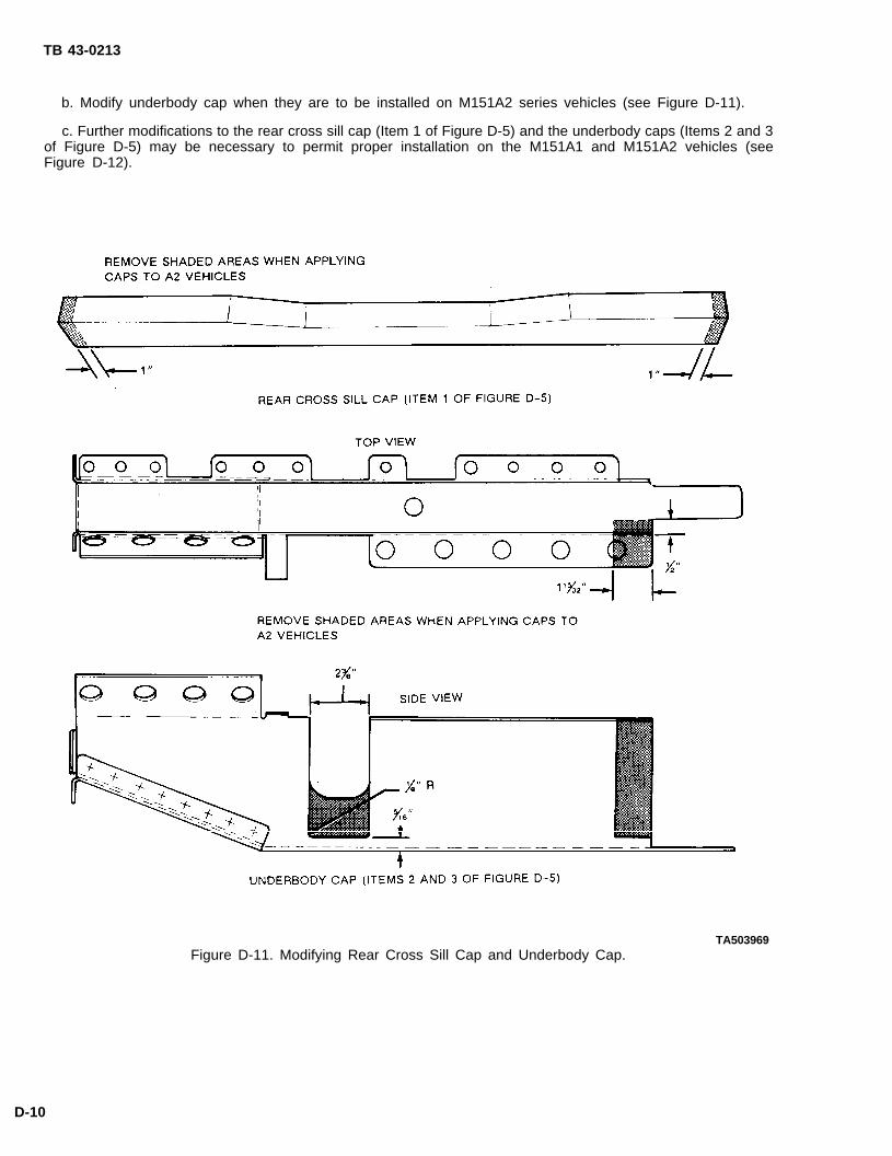
TB 43-0213
b. Modify underbody cap when they are to be installed on M151A2 series vehicles (see Figure D-11).
c. Further modifications to the rear cross sill cap (Item 1 of Figure D-5) and the underbody caps (Items 2 and 3of Figure D-5) may be necessary to permit proper installation on the M151A1 and M151A2 vehicles (seeFigure D-12).
Figure D-11. Modifying Rear Cross Sill Cap and Underbody Cap.TA503969
D-10

TB 43-0213
Figure D-12. Installation Modifications to Items 2 and 3 of Figure D-5.TA504970
D-7. Welding Techniques.
For MIG welding, use Miller Model 10A, or equivalent, set at 30.5 open circuit volts and 5½-inches (14.0 cm)feed with inch (0.80 mm) diameter wire. When electric arc welding, use inch (2.4 mm) AWS7018 rods perMIL-E-2200/1. Use techniques described in FM 43-2 and TM 9-237. Refer to Figure D-13 for examples< of filletand plug welding of underbody caps.
D-11

TB 43-0213
TA504971Figure D-13. Welding Examples.
D-8. Installation of Repair Caps.
CAUTION
Repair caps must be installed in exact item number sequence in order to maintaincorrect flange overlap at all junctions.
a. Position underbody cap over rear sill so that bumperette bolt clearance holes are properly located. Clamp inplace and fillet weld as shown (see Item 1 of Figure D-14).
b. Position underbody caps over rear suspension crossmember so all welding surfaces are in contact withunderbody surfaces. Plug weld and fillet weld as shown (see Items 2 and 3 of Figure D-14).
c. Position underbody caps over rear engine support crossmember so that inboard end of cap fits as close aspossible to main underbody rail. Plug weld and fillet weld as shown (see Items 4 and 5 of Figure D-14).
d. Position two underbody caps over outer center rails. Plug weld and fillet weld as shown (see Item 6 ofFigure D-14).
Position underbody cap over the center rear engine support crossmember. Plug weld and fillet weld as shown(see Item 7 of Figure D-14).
D-12
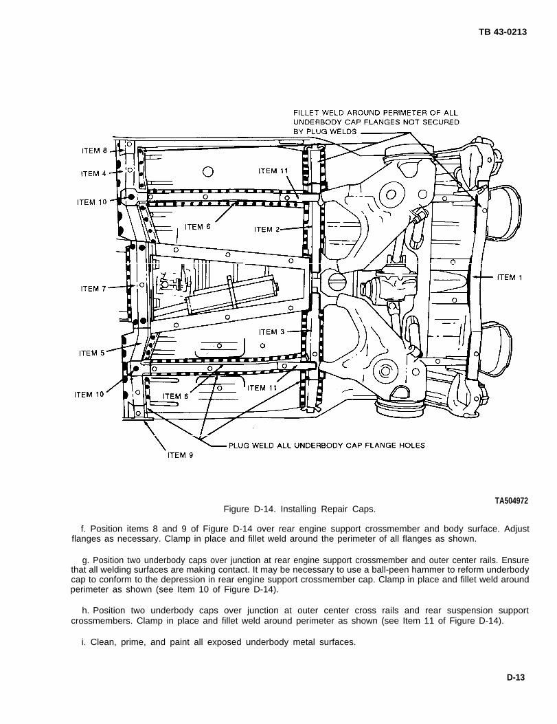
TB 43-0213
TA504972Figure D-14. Installing Repair Caps.
f. Position items 8 and 9 of Figure D-14 over rear engine support crossmember and body surface. Adjustflanges as necessary. Clamp in place and fillet weld around the perimeter of all flanges as shown.
g. Position two underbody caps over junction at rear engine support crossmember and outer center rails. Ensurethat all welding surfaces are making contact. It may be necessary to use a ball-peen hammer to reform underbodycap to conform to the depression in rear engine support crossmember cap. Clamp in place and fillet weld aroundperimeter as shown (see Item 10 of Figure D-14).
h. Position two underbody caps over junction at outer center cross rails and rear suspension supportcrossmembers. Clamp in place and fillet weld around perimeter as shown (see Item 11 of Figure D-14).
i. Clean, prime, and paint all exposed underbody metal surfaces.
D-13

TB 43-0213
D-9. Underbody Component Installation.
a. Install all parts and assemblies removed in paragraph D-4.
b. Reverse the procedures described in paragraph D-2 to upright and lower vehicle to floor.
c. Remove rear turning fixture and install pintle.
d. Remove front turning fixture and install front lifting eyes.
e. Thoroughly clean metal surfaces of gas tank cavity and apply a coat of rustproofing compound as specified inChapter 4 of this technical bulletin.
f. Install all parts and assemblies removed in paragraph D-2.
g. Replace all fluids removed in paragraph D-2 (see LO 9-2320-218-12).
CAUTION
Follow the starting procedure in step h to eliminate the possibility of “hydrostaticlock. “
h. Before starting engine, remove spark plugs and engage starter for 5-10 seconds. Install spark plugs.
D-10. Preventive Maintenance.
a. Rustproof vehicle (see Chapter 4 of this technical bulletin).
b. Perform preventive maintenance checks and services described in TM 9-2320-218-10 and TM 9-2320-218-20-1-1.
Section Ill. INSTALLATION INSTRUCTIONS FOR BODYREPLACEMENT KIT (NSN 2510-01-104-4384)
D-11. Purpose.
a. The purpose of these instructions is to provide a procedure for replacing body assemblies in the restoration ofM151A2 series vehicles.
b. This procedure is to be used when rust damage is too severe to accomplish restoration by installing theunderbody corrosion repair kit, NSN 2520-01-104-4383.
D-12. Materiel Requirements.
a. Table D-2 lists materiel that is provided with the body replacement kit, NSN 2510-01-104-4384. Using thefigure and item numbers listed below, refer to TM 9-2320-218-34P for parts identification and location
b. Serviceable partscomponents not in the
and components will be removed from vehicle and installed on the new body. Part andbody replacement kit that are determined unserviceable will be replaced from stock.
D-14

TB 43-0213
Table D-2. Body Replacement Kit.
Part No. Nomenclature Quantity Figure Item Application
11639700 Body 1 — — Vehicle
MS35338-47 Washer, lock 8 1 2 EngineMS90726-88 Screw 4 1 3 MountsMS27183-16 Flatwasher 2 1 4
7703461 Grommet, Supply Line 1 29 911681689 Clip, Fuel Line 2 29 18 Fuel Tank423437 Screw Assembly 2 29 177345121 Grommet, Vent Line 1 29 19
7331368 Gasket 2 33 1 Exhaust— — — Manifold
MS27183-12 Flatwasher 3 33 6MS51922-9 Nut, Self-Locking 3 33 7MS35751-41 Bolt 3 33 9 Exhaust System7331366 Gasket 3 33 105704853 Parts Kit, Clamp 1 33 —
8754761 Tubing, Drain 2 60 40 Battery Tray
MS35489-20 Grommet, Rubber 2 62 37331198 Grommet, Rubber 1 62 7MS51928-10 Clip, Spring 5 62 9* Front WiringMS51928-5 Clip, Spring 3 62 17* HarnessMS21333-102 Clamp, Loop 3 62 20MS21333-96 Clamp, Loop 1 62 23
MS45904-68 Washer, lock 2 63 28 Front WiringHarness
8724497 Washer 5 See view – Front End of8724495 Shell, Female Electrical 5 2A SH 3 – Rear Wiring
(ref to dwg Harnesspkg in kit)
MS90726-102 Screw 4 — FrontMS90276-86 Screw 2 See view – SuspensionMS90726-98 Screw 2 2A SH 3 – MountingMS51988-10 Nut 8 (ref to dwg – Hardware7046648 Washer 8 pkg in kit) –
MS35489-19 Grommet, Rubber 4 64 1MS51928-3 Clip, Spring 8 64 211599002 Grommet, Plastic 2 64 4 Rear WiringMS51928-8 Clip, Spring 3 64 5 HarnessMS21333-71 Clamp, Loop 1 64 10MS35489-8 Grommet, Rubber 1 64 177728831 Clamp, Loop 1 64 21
. .- Do not remove oId clips from the firewall. New clips must be used to secure wiring harness to new body.
D-15

TB 43-0213
Table D-2. Body Replacement Kit (Con‘t).
Part No. Nomenclature Quantity Figure Item Application
MS35335-33 Washer, lock 5 65 11 TrailerMS35206-281 Screw, Machine 4 65 10 ReceptacleMS51967-2 Nut 1 65 13
MS90726-90 Capscrew 3 76 8 RearMS51988-10 Nut, Self-Locking 3 76 29 Differential
MS51928-3 Clip, Spring 3 83 8 Brake Line
MS90727-95 Capscrew 12 88 1 RearMS51988-10 Locknut 12 88 4 Suspension
MS35692-37 Nut, Slotted 6 91 10 SteeringLinkage
MS90727-98 Capscrew 4 94 3 FrontMS35338-47 Washer, lock 4 94 5 BumperMS51968-11 Nut 4 94 6 Lifting Eye
MS90727-94 Screw, Self-Tapping 8 94 15 Rear Bumperette
MS90725-61 Capscrew 8 96 10 LiftingMS51899-7 Locknut 8 96 12 Eye
MS51922-9 Locknut 8 103 26MS90725-33 Bolt, Machine 6 103 28 WindshieldMS90725-35 Bolt, Machine 2 103 29
7331373 Gasket 1 105 4 Transmission7331372 Gasket 1 105 7 Cover
5703326 Kit, Boot & Seal 1 KIT – TransmissionCover Plate
11663067-1 Reflector 5 122 3 Side11663067 Reflector 2 122 1 Reflectors
MS24665-134 Cotter Pin 2 125 2MS35335-33 Lockwasher 4 125 4MS35206-280 Screw, Machine 2 125 5MS90725-6 Capscrew 2 125 12 Windshield11644889 Gasket, Motor 1 125 13 Wiper MotorMS90725-42 Bolt, Machine 2 125 18MS45904-73 Washer, lock 2 125 1911644876 Bushing, Sleeve 2 125 20
MS35489-9 Grommet, Rubber 1 126 7 WindshieldMS35489-14 Grommet, Rubber 1 126 14 Washer
D-16
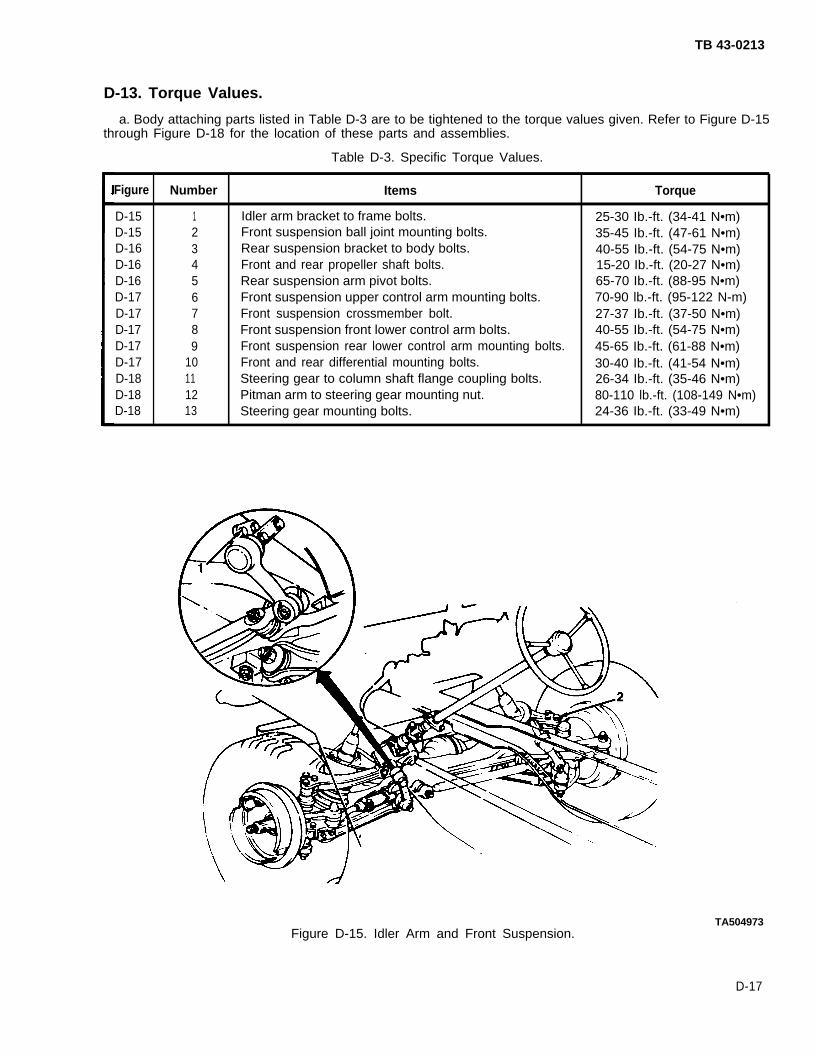
TB 43-0213
D-13. Torque Values.
a. Body attaching parts listed in Table D-3 are to be tightened to the torque values given. Refer to Figure D-15through Figure D-18 for the location of these parts and assemblies.
Table D-3. Specific Torque Values.
Figure Number Items Torque
D-15 1 Idler arm bracket to frame bolts. 25-30 Ib.-ft. (34-41 N•m)D-15 2 Front suspension ball joint mounting bolts. 35-45 Ib.-ft. (47-61 N•m)D-16 3 Rear suspension bracket to body bolts. 40-55 Ib.-ft. (54-75 N•m)D-16 4 Front and rear propeller shaft bolts. 15-20 Ib.-ft. (20-27 N•m)D-16 5 Rear suspension arm pivot bolts. 65-70 Ib.-ft. (88-95 N•m)D-17 6 Front suspension upper control arm mounting bolts. 70-90 lb.-ft. (95-122 N-m)D-17 7 Front suspension crossmember bolt. 27-37 Ib.-ft. (37-50 N•m)D-17 8 Front suspension front lower control arm bolts. 40-55 Ib.-ft. (54-75 N•m)D-17 9 Front suspension rear lower control arm mounting bolts. 45-65 Ib.-ft. (61-88 N•m)D-17 10 Front and rear differential mounting bolts. 30-40 Ib.-ft. (41-54 N•m)D-18 11 Steering gear to column shaft flange coupling bolts. 26-34 Ib.-ft. (35-46 N•m)D-18 12 Pitman arm to steering gear mounting nut. 80-110 lb.-ft. (108-149 N•m)D-18 13 Steering gear mounting bolts. 24-36 Ib.-ft. (33-49 N•m)
Figure D-15. Idler Arm and Front Suspension.TA504973
D-17

TB 43-0213
TA504974
Figure D-16. Rear Suspension and Front and Rear Propeller Shaft.
TA504975
Figure D-17. Front Suspension.
D-18

TB 43-0213
TA504976Figure D-18. Steering Gear.
b. Use standard torque values provided in Table D-4 unless otherwise specified in the applicable technicalmanual or in Table D-3.
D-19
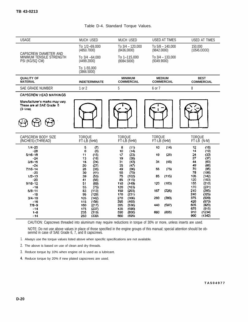
TB 43-0213
Table D-4. Standard Torque Values.
USAGE MUCH USED MUCH USED USED AT TIMES USED AT TIMES
To 1/2–69,000 To 3/4 – 120,000 To 5/8 – 140,000 150,000(4850.7000) (8436,0000) (9842.0000) (10545.OOOO)
CAPSCREW DIAMETER ANDMINIMUM TENSILE STRENGTH To 3/4 –64,000 To 1–115,000 To 3/4 – 133,000PSI (KG/SQ CM) (4499.2000) (8084.5000) (9349.9000)
To 1-55,000(3866.5000)
QUALITY OF MINIMUM MEDIUM BESTMATERIAL INDETERMINATE COMMERCIAL COMMERCIAL COMMERCIAL
SAE GRADE NUMBER 1 or 2 5 6 or 7 8
CAPSCREW BODY SIZE TORQUE TORQUE TORQUE TORQUE(lNCHES)-(THREAD) FT-LB (N•M) FT-LB (N•M) FT-LB (N•M) FT-LB (N-M)
1.
2.
3.
4.
CAUTION: Capscrews threaded into aluminum may require reductions in torque of 30% or more, unless inserts are used.
NOTE: Do not use above values in place of those specified in the engine groups of this manual; special attention should be ob-senmd in case of SAE Grade 6, 7, and 8 capscrews.
Always use the torque values listed above when specific specifications are not available.
The above is based on use of clean and dry threads.
Reduce torque by 10% when engine oil is used as a lubricant.
Reduce torque by 20% if new plated capscrews are used.
T A 5 0 4 9 7 7
D-20

TB 43-0213
D-14. Body Replacement Procedures.
a. Remove components of special purpose kits from old body (see TM 9-2320-218-34-1).
b. Remove soft top and bows, windshield and hinges, hood and front grille, data and instruction plates, allreflectors, seat belts, and seat and frame assemblies (see TM 9-2320-218-20-1-1).
c. Position vehicle on four support stands and new body on four support stands (see Figure D-19 andFigure D-20).
d.
e.plate
f .
TA504978Figure D-19. Positioning Vehicle on Support Stand.
Drain fuel tank and lines (see TM 9-2320-218-20-1-1).
Remove mirrors, wheels, rear shock absorbers, batteries, battery cables, battery box, and transmission cover(see TM 9-2320-218-20-1-1).
Remove front and rear suspension, propeller shafts, and steering gear and column from old body and installon new body (see TM 9-2320-218-34-1). Tighten all mounting hardware to torque values shown in-Table D-3.
g. Remove transmission, shift lever, handbrake assembly, and handbrake lever from old body and install onnew body (see TM 9-2320-218-34-1).
h. Remove drive train (engine, transmission, and transfer assembly) from old body and install on new body (seeTM 9-2320-218-34-1).
i. Remove exhaust system from old body and install on new body (see TM 9-2320-218-20).
j. Remove instrument panel and switches, accelerator, throttle and choke controls, starter switch and bracket,and all light assemblies from old body and install on new body (see TM 9-2320-2 18-20-1-1).
k. Remove flasher unit, trailer receptacle, and front and rear wiring harnesses from old body and install on newbody (see TM 9-2320-218-20-1-2).
D-21160-363 0 - 94 - 8

TB 43-0213
l.(see
TAS04979Figure D-20. Positioning Body on Support Stand.
m.
n.
o.
p.
Remove clutch pedal, brake pedal, master cylinder, and brake lines from old body and install on new bodyTM 9-2320-218-20-1-1).
Remove fuel tank and fuel lines from old body (see TM 9-2320-218-20-1-1).
Apply rustproofing compound to fuel tank cavity in new body (see Chapter 4 of this technical bulletin).
Install fuel tank and fuel lines on new body (see TM 9-2320-218-20-1-1).
Remove all remaining underhood components from old body and install on new body (seeTM 9-2320-218-20-1-1).
q. Remove front and rear bumpers, hood latches, grab handle, and fuel can mounting bracket from old bodyand install on new body (see TM 9-2320-218-20-1-2).
r. Remove all remaining body components from old body and install on new body (see TM 9-2320-2 18-20-1-2).
S. Install rear shock absorbers, battery box, batteries, battery cables, and transmission cover plate on new body(see TM 9-2320-218-20-1-1).
t. Install front grille and hood, windshield and hinges, seat and frame assemblies, and mirrors on new body (seeTM 9-2320-218-20-1-1).
u.
v.
w.
x.
y.
D-22
Install components of special purpose kits on new body (see TM 9-2320-218-34-1).
Rustproof vehicle (see Chapter 4 of this technical bulletin).
Paint vehicle (see TM 43-0139).
Install all reflectors, data and instruction plates, and wheels (see TM 9-2320-218-20-1-2).
Lower vehicle from support stands.

TB 43-0213
z. Install soft top and bows (see TM 9-2320-218-20-1-2).
aa. Return all unused materiel to stock.
D-15. Preparing Vehicle for Service.
a. Aline front wheels and adjust headlights (see TM 9-2320-218-34-1).
b. Perform the preventive maintenance checks and services described in TM 9-2320-218-10 and TM 9-2320-218-20-1-1.
c. Return vehicle to service.
D-23/(D-24 Blank)

TB 43-0213
APPENDIX EFABRICATED TOOLS
Section I. STRAIGHT-EDGE FLOOR SCRAPER
NOTE
All dimensions given in Section I are in standard units.
E-1 . General.
a. After rustproofing a vehicle, the rustproofing compound may drip onto the shop floor creating “pancakes” ofcompound. The process of removing these can be time consuming, even with powerwash equipment and detergents.The most effective way to clean the shop floor is to scrape, then wash the surface down.
b. The straight-edge floor scraper can also be used on certain vehicles, such as the 5-Ton Tractor Truck. Thisvehicle has a hitch platform on the underside which may require scraping to ensure proper function.
c. A 1¼-inch putty knife can be found in the standard shop tool kit and a 4-inch putty knife can be obtainedfrom the supply activity. These tools may serve as a suitable alternative or as a supplement to the fabricated scraper.
E-2. Materials Required.
a. Handle. Use suitable materials or available stock including broken broom handles or worn squeegee handles.
b, Blade. One 13 to 14-inch length of 3/32 by 2-inch sheet metal. Order from supply activity or obtain from weldshop .
c. Support Arms. Two 8-inch lengths of 1/6 by 7/8~inch steel are required. These can obtained from general stockat the nearest weId shop or by ordering item from supply activity.
d.
e.
f .
E-3.
a.
Screws. Four 1/4~inch screws.
Nuts. Four 1/4~inch nuts.
Flatwashers. Eight 1/4~inch hole flatwashers.
Drilling Procedures (See Figure E-1).
WARNING
Drill holes on the flat side of handle to avoid injury or damage to handle.
Handle. Cut a flat surface on one side of the wooden handle that will allow for level contact of blade andsupport arms. After flat surface is cut, drill a 1/4~-inch hole A, 1/2~ inch from the end of the handle. Drill a second1/4-inch hole B that is 4 1/2 to 4 5/8 inches from the hole A.
b. Blade. Drill one 1/4~inch hole C in the middle of the blade 3/8~ inch from the bottom side. Drill two 1/4-inch holesD on each end of the blade, 9/6 inch from their respective sides and half way between the top and bottom edges.
c. Support Arms. Drill two 1/4~inch holes E in each of the two support arms. Holes should be centered and9/16 inches away from the ends.
E-1

TB 43-0213
Figure E-1.Straight-Edge
E-4. Assembly Instructions (See Figure E-1.
TA504980Floor Scraper.
a. Support Arms to Handle, Position one end of both support arms over hole B in handle and install screw, twoflatwashers, and nut.
NOTECenter hole C on blade should be positioned so that scraping edge faces outward.
b. Blade to Handle. Position center blade hole C over handle hole A and install screw, two flatwashers, and nut.
c. Support Arms to Blade. Position free ends of support arms on each side of blade. Install two screws, fourflatwashers, and two nuts.
Section II. LOOPED SCRAPER
WARNING
Wear protective gloves to avoid injury during fabrication of looped scraper. Materialhas sharp edges which may cause serious injury to personnel.
NOTEAll dimensions given in Section II are in standard units.
E-5. General.There are many curved areas underneath a tactical vehicle where a straight-edge scraper or putty knife cannot
reach. The looped scraper will work well on both convex and concave curves.
E-2
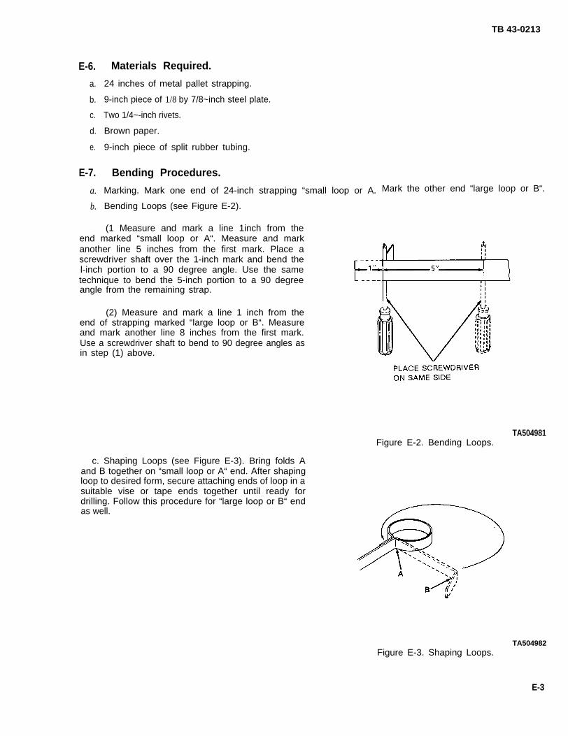
TB 43-0213
E-6.
a.
b.
c.
d.
e.
E-7.
a.
b.
Materials Required.
24 inches of metal pallet strapping.
9-inch piece of 1/8 by 7/8~inch steel plate.
Two 1/4~-inch rivets.
Brown paper.
9-inch piece of split rubber tubing.
Bending Procedures.
Marking. Mark one end of 24-inch strapping “small loop or A. Mark the other end “large loop or B“.
Bending Loops (see Figure E-2).
(1 Measure and mark a line 1inch from theend marked “small loop or A“. Measure and markanother line 5 inches from the first mark. Place ascrewdriver shaft over the 1-inch mark and bend thel-inch portion to a 90 degree angle. Use the sametechnique to bend the 5-inch portion to a 90 degreeangle from the remaining strap.
(2) Measure and mark a line 1 inch from theend of strapping marked “large loop or B“. Measureand mark another line 8 inches from the first mark.Use a screwdriver shaft to bend to 90 degree angles asin step (1) above.
c. Shaping Loops (see Figure E-3). Bring folds Aand B together on “small loop or A“ end. After shapingloop to desired form, secure attaching ends of loop in asuitable vise or tape ends together until ready fordrilling. Follow this procedure for “large loop or B“ endas well.
TA504981Figure E-2. Bending Loops.
TA504982Figure E-3. Shaping Loops.
E-3

TB 43-0213
E-8. Drilling Procedures (See Figure E-4).
a. Ensure that inside portion of loop is even and flush. Mark and punch a 1/4~-inch hole in the center of the l-inchportion and punch through to the 9-inch portion. Follow the procedure for the large loop end as well.
b. Drill two 1/4~-inch holes in the 9-inch metal plate 3/8 inches from the ends.
TA504983Figure E-4. Drilling Scraper.
E-9. Assembly Instructions.
a. Position metal plate in 9-inch strapping so that all holes a line. Use a hand pop-rivet tool to rivet the scraperwith 1/4-inch rivets.
b. Wrap center portion of looped scraper with 9-inch wide brown paper until it will provide a tight fit for the rubber tubing.
c. Place split rubber tubing over center portion of looped scraper.
d. Continue to shape loop ends to desired form.
E-4

TB 43-0213
APPENDIX FGLOSSARY OF TERMS
The following is an alphabetical list of terms found in this technical bulletin. Many of these terms describe designconfigurations found on Army vehicles. Others refer to aspects of corrosion discussed in the introductory chaptersof this technical bulletin.
“A” Pillar Front windshield pillar at door opening.
Access Plug Plastic or rubber plug used to fill holes in sheet metal.
Acid Rain High concentrations of chemical contaminants in the atmosphere which are drivento earth by natural rainfall. Occurs mostly in heavy industrial areas.
Active Metal Describes a metal, such as iron or steel, that is especially susceptible to corrosion.
Additive A compound added to a fuel or lubricant to prevent corrosion, gum formation,varnishing, sludge, and/or knocking.
Baffle
Belt Line
Box Section
Chalking
Channel
Corrosion
cowl
Crevice Corrosion
Dogleg
Doorjamb
Door Skin
Electrolyte
Exfoliation
Eyebrow
Fender Brace
Fender Cap
A hidden obstruction, usually made of sheet metal, used as a support in the designof a vehicle, or to prevent water or dirt from entering the area.
An imaginary line on a vehicle, usually in reference to a line along the bottom of avehicle’s window, or up to and including the rubrail of cargo trucks.
Any area in a vehicle design that is totally or almost totally enclosed.
The breakdown of an organic coating to a powdery, chalky residue.
In vehicle design, an open support member found as U-shaped or A-shaped halfcircle cross sections.
The process of dissolving or wearing away.
That part of a vehicle located between the front windshield and the rear of thehood.
Corrosion occurring in a crevice formed by two or more sections of same or differentmetals.
The arc-like section of a vehicle’s rear support pillar located in from the rear wheelhouse.
See Pillar.
The outer sheet metal of a door.
A chemical substance which contains electrically charged particles capable ofmaintaining or holding an electric current.
The breaking away of surface material into flakes or layers.
Slang term for the extension of the front fender over vehicle headlights.
See Fender Support.
The cap at the end of some fender designs used to either finish the fender or toextend it.
F-1

TB 43-0213
Fender Lip
Fender Reinforcement
Fender Support
Firewall
Flange
Framerail
Front Shield
Galvanic Corrosion
Galvanize
Hat Section
Header Panel
Headlight Bucket
Headlight Rim
Hinge Box
Hinge Pillar
Ipact Bars
Ihibitor
Iorganic Coatings
Inspection Cover
Local Cell
Lock Striker Plate
OEM
Orifico
Oxidation
That part of a fender that is curled under at the wheel opening.
Horizontal strip along the inside of the front fender near the top.
Vertical support and reinforcement at rear of front fender.
The forward, lower wall of a vehicle cab. This wall is located above the area of thevehicle operator’s foot controls and extends from fender to fender, and from cowlto floor pan.
A rim, edge, or collar made of metal and used to strengthen an object, hold it inplace, or attach it to another object.
One of the two main lengthwise members that make up the frame of a vehicle.
Shield under the front bumper of a vehicle used to deflect stones.
Corrosion usually resulting from differing metals of greater/lesser purity which arein contact with one another. The great variance in metal purity works to polarizethe metal. In the presence of moisture, this greater polarity begins to tear down theatomic structure of the weaker of the two metals.
To coat iron with zinc, at time of manufacture, in order to increase the resistance of theiron to rust.
A hat-shaped channel usually found on the underside of a vehicle.
The area above the front grille of some vehicles.
Shield behind headlight to which socket and headlight adjustments are attached.
Trim around headlight and adjustment screws.
The vehicle cab’s support pillar to which the door is hinged.
See Hinge BOX
Reinforcements located inside doors and used to resist impact on the sides.
Chemical substance or mixture which, when added to a solution, decreasescorrosion.
Coatings (usually paint) applied to a surface by electrical/magnetic means, i.e.,electro-deposition. Examples are chrome plating, anodic coatings, conversioncoatings, phosphate coatings, and oxide coatings.
A cover easily removed in order to allow visual or physical access to an enclosed area ofthe vehicle.
A localized area on a vehicle where rust is occurring. An area on the vehicle thatcontains all the elements of rust creation.
That area of the cab pillar post where the door lock strikes and latches when the door isclosed.
An automotive term meaning “Original Equipment Manufactured”.
The hole in the nozzle of a rustproofing spray wand.
The process of electrons combining with atoms of oxygen.
F-2

TB 43-0213
Pillar
Rear Quarter Panel
Rocker Panel
Rubrail
Rust
Rusting
In automotive design, a pillar is any upright support.
Panel or area located on the vehicle side, from the rear wheelwell to the end of thevehicle.
Part of some vehicle bodies, designed as a distinct assembly, located beneath thedoors.
A raised strip running lengthwise on some vehicles such as a cargo truck tailgate.Designed to come in contact with the vehicle when the tailgate is opened. Any railon the side or rear of a vehicle designed to absorb shock.
Iron hydroxide, sometimes referred to as “hydrated ferric oxide”.
The electro-chemical process by which iron or other metals transform into ironhydroxide or rust.
Shock Tower The upper reinforcing member to which a shock absorber is bolted.
Sill Any flat surface or horizontal structure that bears an upright structure, especiallythe base of a window or threshold of a structured doorway.
Skin Slang term referring to the outer metal of a vehicle. Sheet metal or “thin skins”refer to all tactical vehicles and trailers/armor. “Thick skins” refer to most combatvehicles.
Skuff Plate A metal trim cover over a sill panel designed to help resist wear.
Stake Pockets Rectangular openings to accommodate stakes on some truck beds.
Stress Corrosion Cracking Cracking of metal as a result of constant structural stress on a corroding area.
Sweep To move a rustproofing spray tool back and forth across an area while spraying.
Trough A water control channel usually located at edges of doors, deck lid openings, and thecowl-to-firewall seam.
Undercoating Applications of a primer coat. Also the application of a tar-like material on theunderside of a vehicle to serve as a sound deadener.
Upper Radiator Brace Brace between the front fenders which supports the upper part of the vehicle’sradiator.
Wand
Weather Sheet
The tool used to apply rustproofing material.
A plastic or oil paper covering that seals out water or dust from interior trim panels.
F-3/(F-4 Blank)

INDEX
Subject
A
TB 43-0213
Paragraph Page
Abbreviations . . . . . . . . . . . . . . . . . . . . . . . . . . . . . . . . . . . . . . . . . . . . . . . . . . . . . . . . . . . . 1-7 1-3
Acid Rain . . . . . . . . . . . . . . . . . . . . . . . . . . . . . . . . . . . . . . . . . . . . . . . . . . . . . . . . . . . . . . . . 2-17 2-11
c
Cabson 2 1/2-and 5-Ton Trucks:Cleaning Procedures . . . . . . . . . . . . . . . . . . . . . . . . . . . . . . . . . . . . . . . . . . . . . . . . . . .Component installation . . . . . . . . . . . . . . . . . . . . . . . . . . ..... . . . . . . . . . . . . . . . . . .Component Removal . . . . . . . . . . . . . . . . . . . . . . . . . . . . . . . . . . . . . . . . . . . . . . . . . . .Drilling Procedures . . . . . . . . . . . . . . . . . . . . . . . . . . . . . . . . . . . . . . . . . . . . . . . . . . . . .Rustproofing Inspection . . . . . . . . . . . . . . . . . . . . . . . . . . . . . . . . . . . . . . . . . . . . . . . . .Rustproofing Procedures . . . . . . . . . . . . . . . . . . . . . . . . . . . . . . . . . . . . . . . . . . . . . . . .
CARC Paints/Rustproofing Policy . . . . . . . . . . . . . . . . . . . . . . . . . . . . . . . . . . . . . . . . . . . .Cargo Body on 5-Ton Trucks:
Cleaning Procedures . . . . . . . . . . . . . . . . . . . . . . . . . . . . . . . . . . . . . . . . . . . . . . . . . . .Component installation . . . . . . . . .. . . . . . . . . . . . . . . . . . . . . . . . .
Component Removal . . . . . . . . . . . . . . . . . . . . . . . . . . . . . . . . . . . . . . . . . . . . . . . . . . .Drilling Procedures . . . . . . . . . . . . . . . . . . . . . . . . . . . . . . . . . . . . . . . . . . . . . .Rustproofing Inspection . . . . . . . . . . . . . . . . . . . . . . . . . . . . . . . . . . . . . . . . . . . . .Rustproofing Procedures . . . . . . . . . . . . . . . . . . . . . . . . . . . . . . . . . . . . . . . . . . . . . . .
Cargo Body on 2 1/2-Ton Trucks:Cleaning Procedures . . . . . . . . . . . . . . . . . . . . . . . . . . . . . . . . . . . . . . . . . . . . . . . . . . .
Component installation . .. . . . . . . . . . . . . . . . . . . . . . . . . . . . . . . . . . . . . . . . . . .
Component Removal . . . . . . . . . . . . . . . . . . . . . . . . . . . . . . . . . . . . . . . . . . . . . . . . . . .Drilling Procedures . . . . . . . . . . . . . . . . . . . . . . . . . . . . . . . . . . . . . . . . . . . . . . . . . . . . .
Rustproofing inspection . . . . . . . . . . . . . . . . . . . . . . . . . . . . . . . . . . . . . . . . . . . . . . . . .
Rustproofing Procedures . . . . . . . . . . . . . . . . . . . . . . . . . . . . . . . . . . . . . . . . . . . . . . .
Cleaning Procedures:
Cabs, 21/2-and5-Ton Trucks . . . . . . . . . . . . . . . . . . . . . . . . . . . . . . . . . . . . . . . . . . . .Cargo Bodies, 5-Ton Trucks. . . . . . . . . . . . . . . . . . . . . . . . . . . . . . . . . . . . . . . . . . . . .Cargo Bodies, 2 1/2~Ton Trucks. . . . . . . . . . . . . . . . . . . . . . . . . . . . . . . . . . . . . . . . . . . .
Dump Body, 5-Ton Trucks... . . . . . . . . . . . . . . . . . . . . . . . . . . . . . . . . . . . . . . . . . . . .Dump Body, 2 1/2-Ton Trucks. . . . . . . . . . . . . . . . . . . . . . . . . . . . . . . . . . . . . . . . . . . . .Expansible Van Body, 5-Ton Trucks . . . . . . . . . . . . . . . . . . . . . . . . . . . . . . . . . . . . . . .Fuel Tanker, 2 1/2-Ton Trucks, . . . . . . . . . . . . . . . . . . . . . . . . . . . . . . . . . . . . . . . . . . . .
Miniseries Cargo Trailer.. . . . . . . . . . . . . . . . . . . . . . . . . . . . . . . . . . . . . . . . . . . . . .
7-3
7-67-17-27-5
7-41-16
13-313-613-113-213-513-4
8-3
8-6
8-18-2
8-5
8-4
7-3
13-3
8-314-39-3
15-211-2
22-2
7-3
7-77-17-27-6
7-41-7
13-213-513-113-113-513-3
8-2
8-4
8-18-1
8-4
8-2
7-313-2
8-214-69-3
15-2
11-2
22-2
Index 1

INDEX (Con’t)
Subject Paragraph Page
Cleaning Procedures (Con’t):
M105 Series Cargo Trailer . . . . . . . . . . . . . . . . . . . . . . . . .
M151, M718, and M825 Series 1/4-Ton Truck . . . . . . . . . . .
M416 Series Cargo Trailer . . . . . . . . . . . . . . . . . . . . . . . . .
M880 and M890 Series 1 1/4-Ton Truck . . . . . . . . . . . . . . .
M911 Series Tractor . . . . . . . . . . . . . . . . . . . . . . . . . . . . . .
M915 Series Tractor . . . . . . . . . . . . . . . . . . . . . . . . . . . . . .
M966, M997, M998, M1025, M1026, M1035, M1036, M1037,
M1038, M1042, M1044, M1046 Series Trucks . . . . .
M977, M978, M983, M984, M985 Series Trucks (HEMTT)
M1008, M1008A1, M1009, M1010, M1028, andM1031 Series Trucks . . . . . . . . . . . . . . . . . . . . .
VanBody, 2 1/2-TonTrucks . . . . . . . . . . . . . . . . . . . . . . .
Water Tanker, 2 1/2-Ton Trucks. . . . . . . . . . . . . . . . . . .
Wrecker Body, 5-Ton Trucks . . . . . . . . . . . . . . . . . . . . . .
Cleanup instructions, General. . . . . . . . . . . . . . . . . . . . . . . . . .
Component Installation:
Cabs, 2 1/2 and 5-Ton Trucks . . . . . . . . . . . . . . . . . . . . . . .
Cargo Bodies, 5-Ton Trucks . . . . . . . . . . . . . . . . . . . . . . .
Cargo Bodies, 2 1/2 -Ton Trucks . . . . . . . . . . . . . . . . . . . . .
Dump Body, 5-Ton Trucks . . . . . . . . . . . . . . . . . . . . . . . . .
Dump Body, 2 1/2-Ton Trucks . . . . . . . . . . . . . . . . . . . . . .
M151, M718, and M825 Series 1/4-Ton Truck.. . . . . . . . . .
M880 and M890 Series 1 1/4-Ton Truck . . . . . . . . . . . . . . .
M911 Series Tractor . . . . . . . . . . . . . . . . . . . . . . . . . . . . . .
M915 Series Tractor . . . . . . . . . . . . . . . . . . . . . . . . . . . . . .
23-2 23-2
4-3 4-4
21-1 21-1
5-3 5-6
17-3 17-2
18-3 18-2
20-3 20-3
19-3 19-3
6-3 6-3
12-1 12-1
10-2 10-2
16-2 16-1
3-12 3-12
7-6
13-6
8-6
14-6
9-6
4-6
5-6
17-6
18-6
7-7
13-5
8-4
14-9
9-6
4-6
5-12
17-6
18-5
Index 2 -

INDEX (Con’t)
Subject
Component Installation (Con’t):
M966, M997, M998, M1025, M1026, M1035, M1036, M1037,M1038, M1042, M1043, M1044, and M1046 Series Trucks .
M977, M978, M983, M984 and M985 Series Trucks (HEMIT)
M1008, M1008A1, M1009, M1010, M1028,and M1031 Series Trucks . . . . . . . . . . . . . . . . .
Component Removal:
Cabs, 2 1/2- and 5-Ton Trucks . . . . . . . . . . . . . .....
Cargo Bodies, 5-Ton Trucks . . . . . . . . . . . . . . . . . . . . . .
Cargo Bodies, 2 1/2-Ton Trucks. . . . . . . . . . . . . . . . . . .
Dump Body, 5-Ton Trucks . . . . . . . . . . . . . . . . . . . . . . .
Dump Body, 2 1/2 -Ton Trucks . . . . . . . . . . . . . . . . . . . . .
M151, M718, and M825 Series 1/4-Ton Trucks . . . . . . . .
M880 and M890 Series 1 1/4-Ton Trucks . . . . . . . . . . . . .
M911 Series Tractor . . . . . . . . . . . . . . . . . . . . . . . . . . . . .
M915 Series Tractor . . . . . . . . . . . . . . . . . . . . . . . . . . . . .
M966, M997, M998, M1025, M1026, M1035, M1036, M1037,M1038, M1042, M1043, M1044, and M1046 Series Trucks .
M977, M978, M983, M984, and M985 Series Trucks (HEMIT)
M1008, M1008A1, M1009, M1010, M1028,and M1031 Series Trucks . . . . . . . . . . . . . . . .
Corrosion Prevention and Control:
Acid Rain . . . . . . . . . . . . . . . . . . . . . . . . . . . . . . . . . . . .
Crevice Corrosion . . . . . . . . . . . . . . . . . . . . . . . . . . . . .
Four Elements of Rusting . . . . . . . . . . . . . . . . . . . . . . . .
Four Stages of Rust . . . . . . . . . . . . . . . . . . . . . . . . . . . .
Fretting Corrosion . . . . . . . . . . . . . . . . . . . . . . . . . . . . .
Galvanic Corrosion . . . . . . . . . . . . . . . . . . . . . . . . . . . .
Paragraph
20-6
19-6
6-6
7-1
13-1
8-1
14-1
9-1
4-1
5-1
17-1
18-1
20-1
19-1
6-1
2-17
2-13
2-2
2-3
2-15
2-8
Page
20-8
19-7
6-12
7-1
13-1
8-1
14-1
9-1
4-1
5-1
17-1
18-1
20-1
19-1
6-1
2-11
2-9
2-3
2-3
2-11
2-8
Index 3

INDEX (Con’t)
Subject
Mildew . . . . . . . . . . . . . . . . . . . . . . . . . . . . . . . . . . . . .
Ozone and Ultraviolet Radiation. . . . . . . . . . . . . . . . . .
Pitting Corrosion . . . . . . . . . . . . . . . . . . . . . . . . . . . . .
Poultice Corrosion . . . . . . . . . . . . . . . . . . . . . . . . . . . .
Preventive Maintenance for Rust-Prone Areas. . . . . . .
Rust-Prone Areas . . . . . . . . . . . . . . . . . . . . . . . . . . . . .
Stress Corrosion Cracking . . . . . . . . . . . . . . . . . . . . . .
Corrosion Prevention and Control (CPC) . . . . . . . . . . . . . .
Corrosion Removing Compounds, General. . . . . . . . . . . . . .
D
Drilling instructions, General . . . . . . . . . . . . . . . . . . . . . . . .
Drilling Procedures:
Cabs, 2 1/2- and 5-Ton Trucks... . . . . . . . . . . . . . . .
Cargo Bodies, 5-Ton Trucks . . . . . . . . . . . . . . . . . . . .
CargoBodies, 2 1/2-Ton Trucks . . . . . . . . . . . . . . . . .
Dump Body, 5-Ton Trucks . . . . . . . . . . . . . . . . . . . . . .
DumpBody,2 1/2-Ton Trucks . . . . . . . . . . . . . . . . . . .
Expansible Van Body, 5-Ton Trucks... . . . . . . . . . . .
FuelTanker, 2 1/2-Ton Trucks... . . . . . . . . . . . . . . . .
Miniseries Cargo Trailer . . . . . . . . . . . . . . . . . . . . .
M105 Series Cargo Trailer . . . . . . . . . . . . . . . . . . . . .
M151, M718, and M825 Series 1/4-Ton Trucks. . . . .
M880 and M890 Series 1 1/4-TonTrucks . . . . . . . . .
M911 Series Tractor . . . . . . . . . . . . . . . . . . . . . . . . .
M915 Series Tractor . . . . . . . . . . . . . . . . . . . . . . . . .
Paragraph
2-16
2-9
2-10
2-12
2-6
2-5
2-14
1-10
2-19
3-15
Page
2-11
2-9
2-10
2-9
2-7
2-5
2-14
1-4
2-12
3-22
7-2
13-2
8-2
14-2
9-2
15-1
11-1
22-1
23-1
4-2
5-2
17-2
18-2
7-2
13-1
8-1
14-1
9-1
15-1
11-1
22-1
23-1
4-1
5-2
17-1
18-1
Index 4

INDEX (Con’t)
Subject
Drilling Procedures Con’t:
M966, M997, M998, M1025, M1026, M1035, M1036, M1037,M1038, M1042, M1043, M1044, and M1046 Series Trucks .
M977, M978, M983, M984, and M985 Series Trucks (HEMIT)
M1008, M1008A1, M1009, M10110, M1028,and M1031 Series Trucks . . . . . . . . . . . . . . .
Water Tanker, 2 1/2-Ton Trucks . . . . . . . . . . . . . . . . . .
Wrecker Body, 5-Ton Trucks . . . . . . . . . . . . . . . . . . . .
Dump Body and Tailgate for 2 1/2-Ton Trucks:
Cleaning Procedures . . . . . . . . . . . . . . . . . . . . . . . . . .
Component installation . . . . . . . . . . . . . . . . . . . . . . . .
Component Removal . . . . . . . . . . . . . . . . . . . . . . . . .
Drilling Procedures . . . . . . . . . . . . . . . . . . . . . . . . . . .
Rustproofing Inspection . . . . . . . . . . . . . . . . . . . . . . .
Rustproofing Procedures . . . . . . . . . . . . . . . . . . . . . . .
Dump Body and Tailgate for 5-Ton Trucks:
Cleaning Procedures . . . . . . . . . . . . . . . . . . . . . . . . .
Component installation . . . . . . . . . . . . . . . . . . . . . . .
Component Removal . . . . . . . . . . . . . . . . . . . . . . . . .
Drilling Procedures . . . . . . . . . . . . . . . . . . . . . . . . . .
Rustproofing Inspection . . . . . . . . . . . . . . . . . . . . . .
Rustproofing Procedures . . . . . . . . . . . . . . . . . . . . . .
Emission Control Precautions . . . . . . . . . . . . . . . . . .
E
Equipment Maintenance:
Material Pumps . . . . . . . . . . . . . . . . . . . . . . . . . . . . . . . .Emission Control Precautions . . . . . . . . . . . . . . . . . . . . . . . . . .
Paragraph Page
20-2 20-2
19-2 19-1
6-2 6-2
10-1 10-1
16-1 16-1
9-3 9-3
9-6 9-6
9-1 9-1
9-2 9-1
9-5 9-5
9-4 9-4
14-3 14-6
14-6 14-9
14-1 14-1
14-2 14-1
14-5 14-9
14-4 14-7
3-11 3-20
3-63-11
3-93-20
Index 5

INDEX (Con’t)
Sub jec t Paragraph Page
E
Equipment Maintenance Con’t:
PowerWash Equipment . . . . . . . . . . . . . . . . . . . . . . . . . . .
Spray Guns . . . . . . . . . . . . . . . . . . . . . . . . . . . . . . ..
F
Rusting . . . . . . . . . . . . . . . . . . . . . . . . . . . .
Four Stages of Rust . . . . . . . . . . . . . . . . . . . . . . . . . ...
Fretting Corrosion
Fuel Tankerson 2
. . . . . . . . . . . . . . . . . . . . . . . . . . . . . . . . .
1/2-TonTrucks:
Cleaning Procedures . . . . . . . . . . . . . . . . . . . . . .
Drilling Procedures . . . . . . . . . . . . . . . . . . . . . ..
Inspection . . . . . . . . . . . . . . . . . . . . . . . . .
Rustproofing Procedures . . . . . . . . . . . . . . . . . . . .
G
Galvanic Corrosion . . . . . . . . . . . . . . . . . . . . . . . . . . . . . . . . . . .
Glossary . . . . . . . . . . . . . . . . . . . . . . . . . . . . . . . . . ..
H
Hazards, Material . . . . . . . . . . . . . . . . . . . . . . . . . . . . ..
HEMTT Vehicles . . . . . . . . . . . . . . . . . . . . . . . . . . . . . ...
I
Inspections (Fielded Vehicles) . . . . . . . . . . . . . . . . . . . . . . . . . . .
3-4
3-7
2-2
2-3
2-15
11-2
11-1
11-4
11-3
2-8
1-6
1-12
19-1
3-3
3-12
2-3
2-3
2-11
11-2
11-1
11-3
11-3
2-8
1-3
1-5
19-1
3-14 3-21
Index 6

INDEX (Con’t)Subject Paragraph Page
M
Material Hazards . . . . . . . . . . . . . . . . . . . . . . . . . . . . . . . . . . . . .
Material Pumps (Typical):
Operating . . . . . . . . . . . . . . . . . . . . . . . . . . . . . . . . . . . . .
Troubleshooting . . . . . . . . . . . . . . . . . . . . . . . . . . . . . . . .
Mildew . . . . . . . . . . . . . . . . . . . . . . . . . . . . . . . . . . . . . . . . . . .
O
Operating Drum Heaters . . . . . . . . . . . . . . . . . . . . . . . . . . . . . .
Ozone and Ultraviolet Radiation. . . . . . . . . . . . . . . . . . . . . . . .
P
Pitting Corrosion . . . . . . . . . . . . . . . . . . . . . . . . . . . . . . . . . .
Policies/Specifications(Corrosion Prevention and Control). .
Poultice Corrosion . . . . . . . . . . . . . . . . . . . . . . . . . . . . . . . . .
Powerwash Equipment (Typical):
Operating . . . . . . . . . . . . . . . . . . . . . . . . . . . . . . . . . . .
Troubleshooting . . . . . . . . . . . . . . . . . . . . . . . . . . . . . .
Precleaning the Vehicle . . . . . . . . . . . . . . . . . . . . . . . . . . . . .
R
Rain, Acid . . . . . . . . . . . . . . . . . . . . . . . . . . . . . . . . . . . . . . .
Reporting of Equipment improvementRecommendations (Ears) . . . . . . . . . . . . . . . . . . . . . . .
Rust-Prone Areas . . . . . . . . . . . . . . . . . . . . . . . . . . . . . . . . .
Rustproofing Equipment:
Drum Heaters, Operating . . . . . . . . . . . . . . . . . . . . . . .
1-12
3-5
Table 3-4
2-16
3-9
2-9
2-10
1-4
2-12
3-4
Table 3-3
3-13
2-17
1-3
2-5
1-5
3-6
3-14
2-11
3-19
2-11
2-9
1-1
2-9
3-4
3-13
3-21
2-11
1-1
2-5
3 -9 3-19
Index 7

Subject
Rustproofing Equipment Con’t:
Material Pumps (Typical) . . . . . .
Minimum Shop Requirements. . .
Parts/Materials Required . . . . . .
Powerwash Equipment . . . . . . .
Spray Guns . . . . . . . . . . . . . . . .
Wands . . . . . . . . . . . . . . . . . . . .
Rustproofing Inspection:
Cabs, 2 1/2- and 5-Ton Trucks. .
Cargo Bodies, 5-Ton Trucks. . . .
Cargo Bodies, 2 1/2-Ton Trucks.
Dump Body, 5-Ton Trucks . . . . .
Dump Body, 2 1/2-Ton Trucks . .
INDEX (Con’t)
Paragraph
R
. . . . . . . . . . . . . . . . . .
. . . . . . . . . . . . . . . . . .
. . . . . . . . . . . . . . . . . .
. . . . . . . . . . . . . . . . . .
. . . . . . . . . . . . . . . . . .
. . . . . . . . . . . . . . . . . .
. . . . . . . . . . . . . . . . . .
. . . . . . . . . . . . . . . . . .
. . . . . . . . . . . . . . . . . .
. . . . . . . . . . . . . . . . . .
. . . . . . . . . . . . . . . . . .
Expansible Van Body, 5-Ton Trucks. . . . . . . . . . . . . . . .
Fuel Tanker, 2 1/2-Ton Trucks . . . . . . . . . . . . . . . . . . . . .
M101 Series Cargo Trailer . . . . . . . . . . . . . . . . . . . . . . .
M105 Cargo Trailer . . . . . . . . . . . . . . . . . . . . . . . . . . . .
M151, M718, and M825 Series 1/4-Ton Trucks. . . . . . .
M416 Series Cargo Trailer . . . . . . . . . . . . . . . . . . . . . . .
M880 and M890 Series 1 1/4-Ton Trucks . . . . . . . . . . .
M880 and M890 Series 1 1/4-Ton Trucks . . . . . . . . . . .
M911 Series Tractor . . . . . . . . . . . . . . . . . . . . . . . . . . .
M966, M997, M998, M1025, M1026, M1035, M1036, M1037,M1038, M1042, M1043, M1044, and M1046 Series Trucks.
M977, M978, M983, M984, and M985 Series Trucks (HEMTT)
M1008, M1008A1, M1009, M1010, M1028and M1031 Series Trucks . . . . . . . . . . . . . . . .
Van Body, 2 1/2 -Ton Trucks . . . . . . . . . . . . . . . . . . . . .
Index 8
3-5
3-2
3-3
3-4
3-7
3-8
7-5
13-5
8-5
14-5
9-5
15-4
11-4
22-4
23-4
4-5
21-3
5-5
5-5
17-5
20-5
19-5
6-5
12-3
Page
3-6
3-1
3-1
3-3
3-12
3-17
7-6
13-5
8-4
14-9
9-5
15-3
11-3
22-4
23-3
4-13
21-2
5-12
5-12
17-5
20-8
19-7
6-11
12-2

Subject
Rustproofing Inspection Con’t:
INDEX (Con’t)
Paragraph
Water Tanker, 2 1/2-Ton Trucks . . . . . . . . . . . . . . . . . .
Wrecker Body, 5-Ton Trucks . . . . . . . . . . . . . . . . . . . . .
Rustproofing Procedures:
Rust
Cabs, 2 1/2 -and 5-Ton Trucks . . . . . . . . . . . . . . . . . . .
Cargo Bodies, 5-Ton Trucks . . . . . . . . . . . . . . . . . . . . .
Cargo Bodies, 2 1/2-Ton Trucks. . . . . . . . . . . . . . . . . .
Dump Body, 5-Ton Trucks . . . . . . . . . . . . . . . . . . . . . .
Dump Body, 2 1/2-Ton Trucks . . . . . . . . . . . . . . . . . . .
Expansible Van Body, 5-Ton Trucks . . . . . . . . . . . . . . .
Fuel Tanker, 2 1/2 -Ton Trucks . . . . . . . . . . . . . . . . . . . .
M101 Series Cargo Trailer . . . . . . . . . . . . . . . . . . . . . .
M105 Series Cargo Trailer . . . . . . . . . . . . . . . . . . . . . .
M151, M718, and M825 Series 1/4-Ton Trucks. . . . . .
M416 Series Cargo Trailer . . . . . . . . . . . . . . . . . . . . . .
M880 and M890 Series 1 1/4-Ton Trucks.. . . . . . . . .
M911 Series Tractor . . . . . . . . . . . . . . . . . . . . . . . . . .
M915 Series Tractor . . . . . . . . . . . . . . . . . . . . . . . . . .
M966, M997, M998, M1025, M1026, M1035, M1036, M1037,M1038, M1042, M1043, M1044, and M1046 Series Trucks .
M977, M978, M983, M984, and M985 Series Trucks (HEMTT)
M1008, M1008A1, M1009, M1010, M1028,and M1031 Series Trucks . . . . . . . . . . . . . .
Van Body, 2 1/2-Ton Trucks . . . . . . . . . . . . . . . . . . . .
Water Tanker, 2 1/2-Ton Trucks . . . . . . . . . . . . . . . . .
Wrecker Body, 5-Ton Trucks . . . . . . . . . . . . . . . . . . . .
Removing Compounds, General . . . . . . . . . . . . . . . . .
10-4
16-4
7-4
13-4
8-4
14-4
9-4
15-3
11-3
22-3
23-3
4-4
21-2
5-4
17-4
18-4
20-4
19-4
6-4
12-2
10-3
16-3
2-19
Page
10-4
16-4
7-4
13-3
8-2
14-7
9-4
15-2
11-3
22-3
23-3
4-8
21-1
5-6
17-2
18-2
20-4
19-3
6-5
12-2
10-3
16-2
2-19
Index 9

By Order of the Secretary of the Army:
CARL E. WONOGeneral, United States Army
Chief of Staff
Official:
PATRICIA P. HICKERSONColonel, United States Army
The Adjutant General
Distribution:To be distributed in accordance with DAForm 12-25-E, block 0530, maintenance requirements
for TB 43-0213.
U.S. GOVERNMENT PRINTING OFFICE : 1994 0 - 160-363


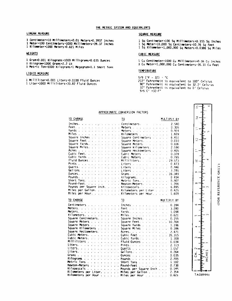

PIN: 039914-000