Embed Size (px)
Citation preview

1
Corrosion phenomena induced by coolant, blanket and fuel salts:
focus on stainless steels and high nickel alloys
Surenkov Aleksandr, Ignatiev Victor, Uglov Vadim
National Research Center “Kurchatov Institute”
2
• For all molten salt reactor (MSR) designs, materials selection is a very important
issue This report summarizes results, which led to selection of materials for
MSRs in the Russian Federation.
• Different forced and natural loops operated in reactor and laboratory conditions
with following molten salt mixtures: LiF-NaF-BeF2+PuF3, LiF-BeF2-UF4, LiF-
BeF2-ThF4-UF4 were tested in Russia. These non-isothermal corrosion tests
were done with stainless steels (H18N10T, EP 164) and high nickel alloys
developed for MSR in Russia (HN80М-VI, HN80МТY, HN80МТW, etc.) including
those developed in USA (Hastelloy–N), Czech Republic (MONICR) and France
(EM-721,) in the temperature range from 600 up to 800oC and mechanical loads
on specimens up to 80 MPa
• The main effort in these studies was focused on the study of selective chromium
corrosion and tellurium intergranular corrosion of the alloys and methods of their
suppression. With that purpose, have been developed devices and methods to
control the redox potential of the melts for different compositions of fluoride salts
containing beryllium and uranium, as well as ways to maintain it at a
predetermined level.
• This report presented and summarized earlier obtained and new data of
corrosion-mechanical tests of Ni alloys and stainless steels on the corrosion loops
Introduction

3
In terms of the decrease in the energy of the formation of fluorides, the metals are
arranged in the series:
Li>Na>K>Be>Th>U3+>Zr>U4+>Al>V>Ti>Mn>Cr>Nb>Fe>Co>Ni>Mo>W
Therefore, the fluorides of the melt do not enter into the oxidation reaction of metals
contained in the alloy.
When there are VF2, TiF2, CrF2, FeF2, NiF2, HF in the melt, there are reactions :
nMe1(s) + mMe2Fn(d) nМе1Fm(d) + mMe2(s), (1),
Where Me1(s) are the metals included in the structural material; Me2(d) -metal, the fluoride of
which is present in the melt as a dissolved impurity. The presence of moisture and oxides in the
structural material (oxide films of nickel, copper, molybdenum, etc.) on its surface in contact with
the fluoride salt is extremely undesirable. In this case, the reactions presented below will occur,
followed by oxidation of chromium and iron in the alloy:
• 2NiO + ZrF4 → 2NiF2 + ZrO2 (5)
• NiO + BeF2 → NiF2 + BeO (6)
• 2NiO + UF4 → NiF2 + UO2 (7)
Corrosion chemistry
• UF4 + 2H2O ↔ UO2 + 4HF (2)
• ZrF4 + 2H2O ↔ ZrO2 + 4HF (3)
• BeF2 + H2O ↔ BeO + 2HF (4)
• The development of effective methods for purification of melts of fluoride salts
from impurities of water and its accompanying oxygen (hydrofluorination), as well as
from metal fluoride impurities (reduction by hydrogen, beryllium or electrolysis)
were successfully implemented on loops in ORNL and then at NRC KI

4
• By the relation (9), the equilibrium concentration of CrF2 in the salt melt increases in
proportion to the square of the ratio of the molar concentration UF4/UF3.
• By changing the uranium ratio [U(IV)]/ [U(III)] downward and maintaining at an
acceptable level, it is possible to minimize the rate of corrosion of the alloy.
• Reduction of diffusion activity of Cr in solid alloys also increases its corrosion
resistance.
In the melt with the fuel component of UF4, the corrosion of the alloys proceeds according
to the reaction:
2UF4(d) + Me(s) ↔ UF3(d) + MeF2(d) (8), where chromium is most vulnerable than Fe, Ni or
Mo. Reaction (8) is reversible, therefore in the fuel circuit with a constant temperature
gradient, chrome from the hot zone will be transported and deposited in the cold zone,
forming a mechanism of continuous corrosion. The initiating factor of mass transfer is the
dependence of the equilibrium constant of the reaction (8) Cr with UF4 on the temperature,
the value of which increases with the temperature in the exponential dependence and is
determined by the relation:
Kp = (XUF3 / XUF4) 2 × (XCrF2 / ACr) (9)
Chromium of the structural material in salts recommended as coolants (LiF-NaF-BeF2, LiF-
BeF2, LiF-NaF-KF, Na-NaBF4) will be oxidized by reactions with impurities of metal fluorides
and complex oxygen ions (CrF3, FeF3, FeF2, NiF2, MoF3, SO42-, PO4
2-, NO3-) or as a result of
reactions with impurities in the surrounding shielding gas.
Chromic corrosion of structural materials

5
Control of the oxidation-reduction state of fuel salts
Electroreduction of U(IV) to U(III)
The voltammetric methodis based on measuring of the
difference between the redox potential of the melt EEQ and E1/2,
the voltammetric equivalent of the standard redox potential E0
of the U(IV)/U(III) couple, at [U(IV)] » [U(III)]. In conditions of
linear voltammetry, at a stationary electrode and a reversible
charge transfer of the melt-soluble oxidized and reduced
forms of uranium, E0 is approximately equal to the
polarographic half-wave potential E1/2 and corresponds to the
potential in the voltammogram, at which the current accounts
for 85.2% of the peak current. If the potential EEQ at
nonpolarizable molybdenum wire, which serves as the quasi-
reference electrode, is equated to zero, [U(IV)]/[U(III)] ratio is
given by the Nernst equation:
-E1/2=RT/nF ln[U(IV)]/[U(III) ] (10)
The melt CVA in corrosion tests with redox condition
([U(IV)]/[U(III)])=20 in fuel melt 70LiF-6.9 BeF2-21ThF4-2.1UF4 at
T=735 0C
Ecp[ (U(IV)]/[U(III)]
=–0.32V
Ecp=0
Dynamic beryllium reference electrode
A diaphragm-free three-electrode meter with a nonstationary
(dynamic) beryllium reference electrode was used to
measure the redox potential of the BeF2 and PuF3 containing
salts. Operation the electrode relies on deposition of a
short-lived beryllium coating on the molybdenum cathode
half-immersed into the melt in a three-electrode
electrochemical cell. After the polarization current is cut off,
the time variation of the emf is measured between the
prepared dynamic beryllium electrode and the molybdenum
indicator electrode, which is irreversible relative to the melt
ions and has a potential equal to the redox potential of the
medium.
Curve 1
Experimental e.m.f. relaxation curves at the DRPM recorded
consecutively during the corrosion experiment in the 15LiF -
58NaF - 27BeF2 melt (mole %) at 650 0С.
Curve 1- in the initial solvent melt, Curve 2- in the solvent melt
treated with metallic beryllium
Curve 2

6
Preparation of salt and purification of loop for corrosion tests
• Interaction of the melt with metal oxides and other corrosion products present on loop surfaces leads to salt contamination by nickel, iron, and chromium compounds.
• Another reason for appearance of these compounds in the melt are traces of moisture on loop surfaces and in powders of initial solvent components (ВeF2 is particularly hygroscopic). In the process of salt heating and melting, water interacts with the material of tank and loop walls and lithium and beryllium fluorides.
Sources of impurities in melt:
1. Content of impurities in initial salt components
2. Adsorbing water at powders of initial
components at conservation and transportation
3. Present of structural materials oxides at inlying
surface of corrosion loop designing after
fabrication and annealing.
The following reactions leads to formation
oxidants of structural materials :
BeF2 + H2O BeO + 2HF ( 12 )
NiO + 2HF NiF2 + H2O ( 13 )
Ni + 2HF NiF2 + H2 ( 14 )
Fe + 2HF FeF2 + H2 ( 15)
Technology clearing of melt salt and
corrosion loop from oxidants by following
processes now are realized step by step:
1. Removal the structural materials oxides from
inlying surface of corrosion loop designing by
washing molten salt solvent 15LiF-58NaF-27BeF2
2. Removal the structural materials oxides and
beryllium oxide from molten salt solvent 15LiF-
58NaF-27BeF2 by clearing mixture of gases HF+
He on reactions of the type:
O2– +2НF 2F– + H2O ( 16 )
3 Electrolysis of the salt melt aimed at removing
the main amount of dissolved nickel.
4. Removal the Ni and Fe fluorides from molten
salt solvent 15LiF-58NaF-27BeF by metallic
beryllium on reduction reactions of the type:
NiF2 + Be BeF2 + Ni ( 17 )
FeF2 + Be BeF2 + Fe ( 18)
7
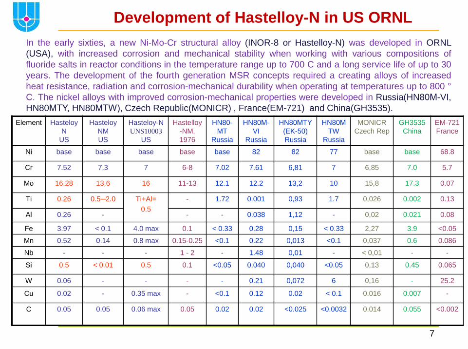
Development of Hastelloy-N in US ORNL
In the early sixties, a new Ni-Mo-Cr structural alloy (INOR-8 or Hastelloy-N) was developed in ORNL
(USA), with increased corrosion and mechanical stability when working with various compositions of
fluoride salts in reactor conditions in the temperature range up to 700 C and a long service life of up to 30
years. The development of the fourth generation MSR concepts required a creating alloys of increased
heat resistance, radiation and corrosion-mechanical durability when operating at temperatures up to 800 °
C. The nickel alloys with improved corrosion-mechanical properties were developed in Russia(HN80М-VI,
HN80МТY, HN80МТW), Czech Republic(MONICR) , France(EM-721) and China(GH3535).
Element Hasteloy
N
US
Hasteloy
NM
US
Hasteloy-N
UNS10003
US
Hastelloy
-NM,
1976
HN80-
MT
Russia
HN80М-
VI
Russia
HN80МTY
(EK-50)
Russia
HN80М
TW
Russia
MONICR
Czech Rep
GH3535
China
EM-721
France
Ni base base base base base 82 82 77 base base 68.8
Cr 7.52 7.3 7 6-8 7.02 7.61 6,81 7 6,85 7.0 5.7
Mo 16.28 13.6 16 11-13 12.1 12.2 13,2 10 15,8 17.3 0.07
Ti 0.26 0.5─2.0 Ti+Al=
0.5
- 1.72 0.001 0,93 1.7 0,026 0.002 0.13
Al 0.26 - - - 0.038 1,12 - 0,02 0.021 0.08
Fe 3.97 < 0.1 4.0 max 0.1 < 0.33 0.28 0,15 < 0.33 2,27 3.9 <0.05
Mn 0.52 0.14 0.8 max 0.15-0.25 <0.1 0.22 0,013 <0.1 0,037 0.6 0.086
Nb - - - 1 - 2 - 1.48 0,01 - < 0,01 - -
Si 0.5 < 0.01 0.5 0.1 <0.05 0.040 0,040 <0.05 0,13 0.45 0.065
W 0.06 - - - - 0.21 0,072 6 0,16 - 25.2
Cu 0.02 - 0.35 max - <0.1 0.12 0.02 < 0.1 0.016 0.007 -
C 0.05 0.05 0.06 max 0.05 0.02 0.02 <0.025
<0.0032
0.014 0.055 <0.002

8
Corrosion resistance of Hastelloy-N alloy
* - Calculated value for the diffusion-kinetic model
Full-scale resource lab tests on loops with natural and forced circulation in various fuel compositions at temperatures up to
700 0С and reactor tests of the Hastelloy-N alloy in MSRE showed its high resistance to selective corrosion of chromium.
Test loop Structural
material Molten salt,
% mole
Fluid test conditions Talloy o C
Corr.
rate
μm/yr Circulation mode T max
о С Δ Тmах
о С Exposure
hrs NCL-1258 Stainless steel
S-304L 70LiF-23BeF2-
5ZrF4-1UF4 Natural convection 688 100 6100
79400 688
688
53
26
NCL-22 Stainless steel
S-316 71.7LiF-16BeF2-
12UF4-0.3ThF4 Natural convection 650 110 4298 650
23
NCL-16 Hastelloy–N
Hastelloy–N,
mod. Ti≤0.5
66.5LiF–34BeF2-
0.5UF4
Natural convection
V=2.5cm/s 704 170 28000 660
675
700
1.0(1.0*)
0.5
0.9 MSRE Hastelloy –N 65LiF-29.1BeF2-
5.0Zr F4-0.9UF4
Fuel circuit
circuit 654 22 21800 654 8.0(1,6*)
66LiF–34BeF2 Coolant circuit 580 35 26100 580 no NCL-15A Hastelloy –N 73LiF-2BeF2-5ThF4 Natural convection
V=0.7cm/s 677 55 35400 677 1.5
NCL-21A Hastelloy –N
Hastelloy–N,
mod. 1%Nb
71.7LiF-16BeF2-
12ThF4-0.3UF4
Natural convection
V=1 cm/s U4+/U3+≈104 704 138 10009
1004
704
704 3.5 (3.1*)
3.7
NCL-23 Inconel 601 71.7LiF-16BeF2-
12ThF4-0.3UF4
Natural convection
V=1 cm/s, U4+/U3+≈40 704 138 721 704 ≥34
NCL-24 Hastelloy–N,
mod. 3.4%Nb 68LiF-20 BeF-
11.7ThF-0.3UF4 Natural convection 704 138 1500 704 2.5
FCL-2b Hastelloy –N
Hastelloy–N mod. 1%Nb
71.7LiF-16BeF2-
12ThF4-0.3UF4
Forced convection
V=2.5–5 m/s U4+/U3+≈100
704 138 4309
2242 704
704 2.6(2.5*)
0.4
FCL-2 Hastelloy –N
92NaBF4-8NaF V=2.3 m/s
V=6.2 m/s 620 170 5100
5100 620
620 12
16

9
Development status of Ni-based alloys at ORNL
•Hastelloy N alloy was the sole structural material used in the Li,Be,Zr,U/F MSRE and contributed significantly
to the success of the experiment. Less severe corrosion attack (<1mil per year) was seen for the Hastelloy N in
contact with the MSRE fuel salt at temperatures up to 704oC for three years (26,000 hours).
•Hastelloy N used for the MSRE was subject to a kind of "radiation hardening," due to accumulation of helium at
grain boundaries.
•In MSRE was found tiny cracks on the inside surface of the Hastelloy N piping. These cracks were caused by
the fission product tellurium.
•The research toward finding a material for constructing a MSR that has adequate resistance to irradiation
embrittlement and intergranular cracking by tellurium has progressed.
•ORNL findings suggest that MSR could be constructed of 1-2%-Nb-modified Hastelloy N and operated
satisfactorily at 650oC.
Variations of severity of cracking with Nb content. Samples
was exposed for indicated times to salt containing Cr3Te4 and
Cr5 Te6 at 700C.
Cracking behavior of Hastelloy-n exposed 260 hr of 700 C to MSBR fuel
salt containing CrTe1.266 .

10
Development of HN80MTY alloy(EK-50) in NRC KI
•The development of Russian domestic structural material for MSR was substantiated by available
experience accumulated in ORNL MSR program on nickel -base alloys for UF4 -containing salts.
Ampoule corrosion tests were conducted at temperatures of 650 and 800 ° C. The alloy HN80MT was
chosen as a base. Its composition (in wt.%) is Ni(base), Mo(12.2), Cr(6.9), Ti(1.7), C(0.02). The
development and optimization of HN80MT alloy was envisaged to be performed in two directions:
improvement of the alloy resistance to a selective chromium corrosion,
increase of the alloy resistance to tellurium intergranular corrosion and cracking.
•About 70 differently alloyed specimens of the HN80MT were tested. Among alloying elements there
were W, Nb, Re, Y, V, Al and Cu. The main finding is that alloying by aluminum at a decrease of
titanium down to 0.5% revealed the significant improvement of both the corrosion and mechanical
properties of the alloy. Irradiation effect on a corrosion activity of fuels was also studied. It was shown
that at least up to the power density 10 W/cm3 in fuel composition LiF–BeF2–ThF4–UF4 there is no
radiation induced corrosion.
•Then the radiation study of 13 alloy modifications were carried out. Specimens (in nitrogen
atmosphere) were exposed to the reactor neutron field up to the fluency of 3·1020 n/cm2. Experimental
results of alloy mechanical properties at temperatures of 20, 400 and 650°C for nonirradiated and
irradiated specimens permits to rest only four modifications. These alloys modified by Ti, Al and V
have shown the best postirradiation properties.
•The results of combined investigation of mechanical, corrosion and radiation properties various
alloys of HN80MT permitted us to suggest the Ti and Al-modified alloy as an optimum container
material for the MSR. This alloy named HN80MTY (or EK-50).

11
Results of corrosion tests at NRC KI with molten fluoride salts
Loop NRC KI Salt,
in mole %
Specimens
material
Тmax , С Т, С Duration
hr
Corrosion
rate, μm/yr
Solaris 46.5LiF-11.5NaF-42KF 12H18N10T
HN80МТ
620 20 3500 250
22
KI C1
КI С2
КI С3
92NaBF4-8NaF 12X18H10T
AP - 164
HN80МТ
630
630
630
100
100
100
1000
1000
1000
250
50
12
КI M1 66LiF- 34BeF2+UF4 12H18N10T 630 100 500 20
KURS-2 66LiF -34BeF2+UF4 12H18N10T 750 250 750 25
КI F1
КI F2
71.7LiF-16BeF2-12ThF4-
0.3UF4+Te
HN80МТ
HN80МТY
750
750
70
70
1000
1000
3.0
6.0
NCL-1
15LiF-58NaF-27BeF2 +PuF3
HN80M-VI
HN80МТY
MONICR
700
100
1600
5
5
19
КI Тe1
15LiF-58NaF-27BeF2 +Cr3Te4
HN80M-VI
HN80МТY
MONICR
700
10
400
3
3
15
KI Te2
75LiF-5BeF2-20ThF4 +(0.27-
2.1)UF4 + Cr3Te4
Average value [U(IV)/U(III)] = 5
HN80M-VI
HN80МТY
HN80MTW
EM 721
730
735
735
735
40
250
29
57
28
10
KI Te3
73LiF -27BeF2+ 2.0UF4
+Te(metal)
Average value [U(IV)/U(III)]= 45
Hastelloy N
HN80МТY
HN80MTW
EM- 721
760
40
256
21(20*)
8
12
22
73LiF -27BeF2+ 2.0UF4
+Te(metal)
Average value [U(IV)/U(III)]=85
Hastelloy
NHN80МТY
HN80MTW
EM 721
800
780
800
800
40
248
45(56*)
52
63
55
* - Calculated value for the diffusion-kinetic model

12
Corrosion resistance of alloys in 8NaF-92NaBF4
Structural
material
Fluid test conditions Content impurities before test,
10-4 mass %
Pres
ence
IGC
Corr.
rate
μm/yr Circulation
mode
T max о С
Δ Тmах о С
Exposur
e
hrs
Fe Ni Cr H2O for
oxygen
12H18N10T
EP-160
Isothermal
condition
420 0 500 11 1.0 0.5 <103
Yes
Yes
-91
-10
12H18N10T
EP-160
Isothermal
condition
630 0 500 11 1.0 0.5 <103
Yes
Yes
-150
-78
S-304
(ORNL)
Isothermal
condition
600 0 100 - - - - -134
XN80MT
XN80MTY
Isothermal
condition
630 0 500 11 1.0 0.5 <103
No
No
-12
-12
12H18N10T
EP-160
Natural
convection
V=2 cm/s
630
630
95 500 11/35
0
1.0/1.2 0.5/650 <103 Yes
Yes
-250
-50
12H18N10T
EP-160
535 95 500 11/35
0
1.0/1.2 0.5/650 <103 No
No
+70
+20
Hastelloy-N Isothermal
condition
600 0 100 - - - - -7
Hastelloy-N
mod. 0.5Ti
Natural
convection
V=3.6 cm/s
607
460
147 500 223/
650
28/
95
19/348 800/
2800
No
No
-18
+18
Stainless steel EP-164: base – Fe, 22-25Ni, 14-16Cr, 0.5-1.0 Mn, 1.4-1.8Ti, 4.0-5.0W, 0.6Si, 0.025 Ce, 0.12C (%mass)
Corrosion rate of alloys in coolant 8NaF-92NaBF4 fluoride salt
• Corrosion of 12H18N10Т and EP-164 in the 8NaF-92NaBF4 (mol %) was studied in the RRC KI in natural circulation corrosion loop
with a maximum temperature of 630oC for 500 hrs exposure time.
• Under these conditions, the uniform corrosion rate for EP-164 was 5 times less than that of steel 12H18N10T. The depth of the
surface defects for both alloys is 60-70μm. The data obtained in ORNL for similar test conditions of SS-304L are in agreement with
our data for 12H18N10T. The maximum corrosion rate for these steels in a NaF-NaBF4 natural convection loop was 250 μm/yr.
• The ORNL data for natural convection loops where the NaF-NaBF4 salt was heated from 400 °C to 600 °C, the corrosion of the
Hastelloy-N alloy lies in the range of 5-20 μm/yr and this value was usually determined by the degree of coolant purification

13
Li,Be,Na,(Pu)/F Loop Corrosion Studies
Results of 1200 hrs loop corrosion experiment with on-line redox potential measurement demonstrated that high temperature operations with molten 15LiF-58NaF-27BeF2 salt are feasible using carefully purified molten salts and loop internals. In established interval of salt redox potential 1.25-1.33 V relative to Be reference electrode, corrosion is characterized by uniform loss of weight from a surface of samples with low rate (2-5μm/yr for HN80М-VI and HN80МTY alloys and 9-19 μm/yr for MONICR).
It was not found any significant change in corrosion behavior of materials samples in melt due to the presence of 0.5 mole % PuF3 addition in Li,Be,Na/F salt. Specimens of HN80M-VI from the loop exposed during 400 hrs at temperature 650C showed uniform corrosion rate <6 μm/yr.
No intergranular corrosion of alloys is observed in the loop.
MONICR
HN80MTY
HN80M-VI
Cr,
mas
s.%
μm
μm
μm
Cr,
mas
s.%
Cr,
mas
s.%
Main parameters of the corrosion loop: • Salt composition 58NaF-15LiF-27BeF2 +PuF3
• Temperature salt melt in zone of exposition of specimens- 620-700oC
• Difference of salt temperature on circuit of circulation–in limits 80-100oC
• Salt velocity in circuit of circulation - in limits 1-5 cm/sec
• Structural material of corrosion loop - nickel NP-2 (99.5 Ni)
• Material of investigated alloys:HN80M-VI (Hastelloy N modified 1.48%Nb),
HN80MTY (1.12 %, Al- 0.93 %Ti), MONICR (Hastelloy N modified 2.27%Fe)

14
The alloy resistance to intergranular cracking is estimated by parameter “K”, representing number of cracks at
length of 1 cm longitudinal section of sample subjected to deformation of a stretching, multiplied by their average
depth in micrometers.The second criterion was maximum depth of cracks (in μm). Data NRC-KI ampule and
71.7LiF-16BeF2-12ThF4-0.3UF4 loop tests containing metallic Te permit us to make the following conclusions:
Te damage of Ni-Mo alloys (NRC КI, 1976 -1986)
1. Alloying by niobium to 1% without titanium reduces significantly the value "K" to 190 pcm/cm (for Hastelloy N-mod. K=1090 pcm/cm). 2. Alloying by niobium with titanium which is necessary in the alloy for ensuring post -radiation properties, resulted in the increase of “K" parameter at 650°C to 6850 pcm/cm. Thus, admitting the niobium as an element capable of increasing the alloy resistance to intergranular cracking, it should be also noted to reduce content of Ti to an acceptable level, which ensures the required radiation resistance. Such a method of alloying, while permits to improve significantly corrosion and radiation characteristics of material, but is not the radical solution. 3. Alloying a standard Hastelloy N modified by 0.5% of aluminum did not improve its corrosion properties, though enhanced markedly its mechanical characteristics. 4. Alloying by aluminum at a decrease of titanium up to 0.5% revealed the significant improvement of both the corrosion and mechanical properties of the alloy.
Structure subsurface layer of HN80МТ, HN80МТY and Standard
Hastelloy-N specimens after 500 hrs exposure in 71.7LiF-16BeF2-
12ThF4-0.3UF4 containing tellurium :
HN80МТ, isothermal test at Т=600С
HN80МТ, isothermal test at Т=750С
HN80МТ, nonisothermal loop test at
Т=750С, Т = 70С
Standard Hastelloy-N, isothermal test
at Т=700С
HN80МТY, isothermal test at Т=750С
HN80МТY, nonisothermal loop test at
Т=750С, Т = 70С
К=1300 pc x mμ/cm
К=2100 pc x mμ/cm
К=5440 pc x mμ/cm
К=9130 pc x mμ/cm

15
F
Without load
With load 80 MPa
MONICR
MONICR
ХН80М-ВИ ХН80М-ВИ
ХН80МТЮ
ХН80МТЮ
Т=700С
Е=1,2В К=690 pc / cm × μm
К= 1560 pc / cm × μm
К=380 pc / cm × μm
К=680 pc / cm × μm
К>10000 pc / cm × μm
К=3590 pc / cm × μm
Resistance of Ni-Mo alloys to Te corrosion depend on:
(1) melt redox potential, (2) thermal- mechanical loads,
(3) exposure time, (4) doping elements in alloy
К= 0 pc / cm × μm
Studies on alloy’s resistance to IGC, should
be continued in corrosion loops with thermal
gradient and longer exposure t=250hr, Cr3Te4 as a
source of tellurium
0 50 100 150 200 250
,hous
0.0
0.2
0.4
0.6
0.8
1.0
1.2
1.4
E, V
t
Te corrosion of Ni-Mo alloys in 15LiF-58NaF-27BeF2 melt without and under
mechanical load in dynamic conditions at 700 ºC and redox potential control
ХН80МТ alloyed by Mn
ХН80МТ alloyed by 0.56Nb1-1.0Ti
К= 3370 pc / cm × μm

16
Te intergranular corrosion in fuel salts
Elements of facility : tank lid (1), device for measuring redox potential (2), beryllium reducer
3), sampler salt (4); the dosing device of chromium telluride (5), cassettes of specimens of
alloys (6)
F
Ar
T
Ar
Ep
Cr3Te4
1
4 6
5
2 3
Ep=0
Ecp [U(IV)/U(III)]
=+0.03V
Test 1 after processing by beryllium –
[U(IV)] /[U(III)] = 0.7, fuel
75,36LiF-4BeF2-20ThF4-0,27UF4-0.37UF3 salt
Ecp [U(IV)/U(III)]
=–0.32V Ep=0
Ecp [U(IV)/U(III)]
=–0.70 V
Ep=0
Test 3 after fist addition 120 g NiF2 -
[U(IV)] /[U(III)] =20, fuel
70LiF–6,9BeF2–21ThF4–2,1UF4 salt
Test 4 after second addition 120 g NiF2 -
[U(IV)] /[U(III)] = 500, fuel
70LiF–6,9BeF2–21ThF4–2,1UF4 salt
The present study tellurium corrosion envisages five compatibility testing of nickel- based alloys, with the fuel salt with high content
of ThF4 (up to 20 mol.%) and UF4 (up to 2 mol.%) additives in the melt containing Cr3Te4, with a duration of 250 hours each, with the
change uranium ratio [U(IV)]/[(III) ] from ~ 1 to 500, in the temperature range from 720 to 750 C and mechanical stress on the samples
from 0 to 50 Mpa. Melt composition 75LiF-5BeF2-20ThF4 (%mol.) with the addition UF4 to 2 mol.% was selected for research

17
Alloy HN80M-VI 1.5%Nb K=8300 pc/cmx μm T=7500C
Alloy HN80MTY 1.1%Al, 0.9%Ti K=1850 pc/cmx μm T=750 0C
Alloy HN80MTW 1.7%Ti, 5.5%W K=8400 pc/cmx μm K=540 pc/cmx μm,T=7450C
Alloy EM721: 69Ni-25W-6Cr K=9200 pc/cmx μm T=750 0C
Te corrosion of Ni alloys in Li,Be,U/F melt
Test conditions: 735oC after 250 hrs with mechanical loading 25 MPa U(IV)/(UIII) ≈ 0.7 U(IV)/(UIII) ≈ 4.0. U(IV)/(UIII) ≈ 20 U(IV)/(UIII) ≈ 500 U(IV)/(UIII) ≈ 100

18
The reaction
2UF3 + СrF2 + Te0 → 2UF4 +
СrTe
at U(IV)/(UIII) <100 blocks
the transfer of free Te to the
structural material and
prevents the corrosion
Resistance of Ni-Mo alloys to Te IGC in Li,Be,U/F melt
Test 1
Average U(IV)/U(III)=45
760oC
Metallographic studies of alloy samples show a clearly pronounced dependence of the intensity of Te IGC on the oxidation-reduction potential and the temperature of the melt.
0
50
100
150
200
250
300
350
0 25 50 75 100 125 150 175 200 225 250
[U(I
V)]
/[U
(III
)]
K=530pc×μm/cm
l=26μm
K=5820pc×μm/cm
l=126μm
K=3500pc×μm/cm
l=69μm
K=5830pc×μm/cm
l=286μm K=4490pc×μm/cm
l=148μm
K=3490pc×μm/cm
l=290μm
K=3380pc×μm/cm
l=178μm
Test 2
Average
U(IV)/U(III)=60
750oC
Test 3
Average
U(IV)/U(III)=85,
800oC
Redox potential of the fuel salt 71LiF-27BeF2-2UF4 during the tests
Test 1. Test 3
EM-721 HN80MTY HN80MTW Ni-12Mo-7Cr-1.0Nb Hastelloy-N
UNS10003

19
• Structural materials recommended for fuel and intermediate circuit MSR are special
Ni-Mo alloys with low chromium concentration. The composition of the reference
Hastelloy-N alloy was optimized by researchers in ORNL (USA) for corrosion
resistance (in the gaseous atmosphere and in molten fluorides), for radiation
resistance and mechanical properties at high temperature.
• It is shown, that the redox potential of salt is a key parameter in the corrosion of
MSR constructional materials. A redox-buffer pair (for example in a fuel salt ratio
(UF4/UF3) can control chemical corrosion. For individual cooling salt compositions
(46.5LiF-11.5NaF-42KF), such redox-buffer pair should be matched.
• New materials are developed and tested in the Russian Federation, China (Ni-Mo-Cr
alloys), France (Ni-W-Cr alloys). The Russian nickel alloy HN80MTY, doped with Ti
and Al, is the most resistant to intergranual tellurium cracking when tested with
molten salts of Li,Th,U/F and Li,Be,Th,U/ F up to a temperature of 800 oC and with a
redox-potential salt [U(IV)]/[U(III)] having a value of ≤100.
• Detailed studies of the kinetics of the boundary diffusion of tellurium in candidate
alloys and the mechanism of their tellurium intergranular embrittlement should be
carried out under nonisothermal conditions simulating the operation mode of the fuel
circuit of the MSR. The metallurgy and properties of these alloys should be studied
in more detail in the future and especially with regard to the resistance to irradiation
and the possibility of manufacturing the required assortment of materials.
Summary