Embed Size (px)
Citation preview

ULTRASONIC INTELLIGENT SENSORS
Corrosion Monitoring system through 'surf-board'
communication by satellite
Geir Instanes,
Vice President, ClampOn

ULTRASONIC INTELLIGENT SENSORS
Presentation Layout Corrosion-Erosion Monitor - CEM
• Subsea….
• Introduction and Background
• System properties
• System layout
• Subsea Installation Options
• Conclusion
ULTRASONIC INTELLIGENT SENSORS
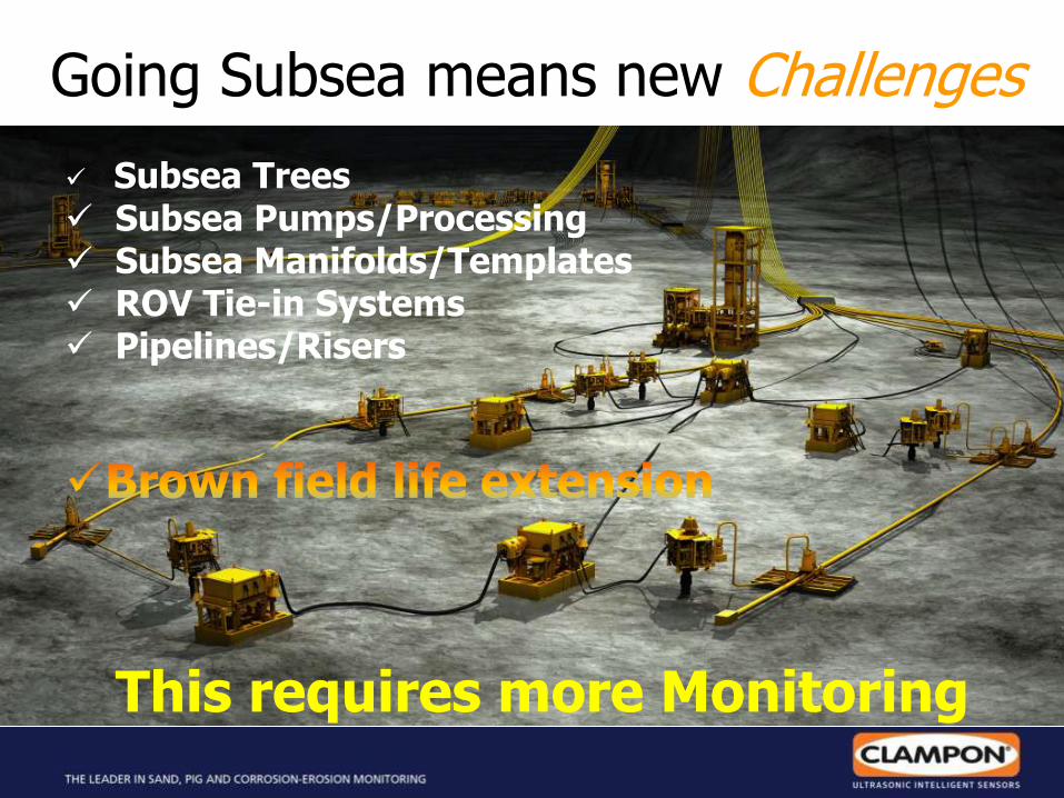
Going Subsea means new Challenges
Subsea Trees Subsea Pumps/Processing Subsea Manifolds/Templates ROV Tie-in Systems Pipelines/Risers
This requires more Monitoring

ULTRASONIC INTELLIGENT SENSORS
System in the field - Topside

ULTRASONIC INTELLIGENT SENSORS
The Corrosion Monitoring System
Data Communication
Syst
em
in t
he f
ield
- S
ubse
a

ULTRASONIC INTELLIGENT SENSORS
Working Principle - Lamb Waves Corrosion-Erosion Monitor
• AGLW = Acoustic Guided Lamb Waves
• Named after Horace Lamb, who discovered the waves in 1916
• Also called Long Range NDT
• The pipe wall will force the transmitted signal into a given shape and form (mode generation)
• Analytical inversion of acoustic data to obtain relevant thickness information

ULTRASONIC INTELLIGENT SENSORS
• Measures WT between the transducers in “line of sight” • Resolution/sensitivity better then 1% of WT • Signal is Robust and will not break down
• Transducers can be mounted on the outside of coating <1mm /0.04” thickness

ULTRASONIC INTELLIGENT SENSORS
• Measures WT between the transducers in “line of sight” • Resolution/sensitivity better then 1% of WT • Signal is Robust and will not break down
• Transducers can be mounted on the outside of coating <1mm /0.04” thickness

ULTRASONIC INTELLIGENT SENSORS
• Measures WT between the transducers in “line of sight” • Resolution/sensitivity better then 1% of WT • Signal is Robust and will not break down
• Transducers can be mounted on the outside of coating <1mm /0.04” thickness

ULTRASONIC INTELLIGENT SENSORS
CEM Coverage area
Transducer 1 Transducer 2
• The figure illustrates the area covered by a pair of transducers
• Beam divergence allows the CEM to „see‟ a large area
• A matrix of transducers deployed on a region of pipe can provide comprehensive coverage
• The larger WT the larger the coverage area is

ULTRASONIC INTELLIGENT SENSORS
CEM
- C
overa
ge A
rea
• OD pipe – 8”
• Separation 700 mm
• 6 Transducers set-up Total Coverage:
• ≈ 90% (of inspected area)
• Each path width is 70mm

ULTRASONIC INTELLIGENT SENSORS
CEM
- C
overa
ge A
rea
• OD pipe – 8”
• Separation 700 mm
• 6 Transducers set-up
Total Coverage:
• ≈ 90% - topline corrosion
• Can be calculated by Software
5
7
8
4
1
3
Transducers
Pipe Unfolded
Pipe / Plate
Top line
Bottom
Bottom

ULTRASONIC INTELLIGENT SENSORS
CEM
- C
overa
ge A
rea

ULTRASONIC INTELLIGENT SENSORS
CEM - Tomography
• The more transducers that is used - better coverage and depth measurement
• CEM can then “Measure” minimum wall thickness and locate the defects.
• Has been simulated, tested and demonstrated
…… software upgrade
CEM
- C
overa
ge A
rea

ULTRASONIC INTELLIGENT SENSORS
Comparison – Coverage Area
COVERAGE AREA –
THE MEASURED AREA THAT THE SYSTEMS ARE COVERING:
a) 2 x CEMAT Transducer separated by 600mm. Coverage area = 35 000 mm2
b) Alternative 14 spots (el 5mm) each covering 19,5mm2 = 273 mm2
c) Alternative 8 spots (el 12mm) each covering 113mm2 = 904 mm2
OR
d) 8 CEMAT Transducer distributed over the selected surface: <65% of the surface, which equals to: 187 000 mm2.
= Large coverage with less transducers/equipment

ULTRASONIC INTELLIGENT SENSORS
Uniform thickness loss
CEM demonstration – uniform thickness reduction

ULTRASONIC INTELLIGENT SENSORS
General Wall loss ClampOn DSP Corrosion-Erosion Monitor
Milling out a wide defect
9 milling operations
250 mm probe separation on Plate 4
-2
2
6
10
14
18
22
26
30
1 2 3 4 5 6 7 8 9
Run number
% d
rop
in
avera
ge . W
Estimated % drop in average WT
Measured % drop in average wall thickness
Witnessed by:
BP, Statoil,
Hydro and Shell
ULTRASONIC INTELLIGENT SENSORS
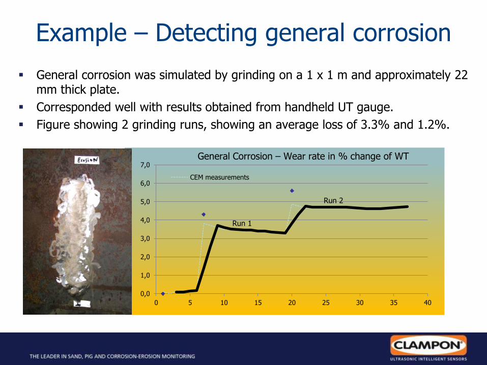
Example – Detecting general corrosion
General corrosion was simulated by grinding on a 1 x 1 m and approximately 22 mm thick plate.
Corresponded well with results obtained from handheld UT gauge.
Figure showing 2 grinding runs, showing an average loss of 3.3% and 1.2%.
0,0
1,0
2,0
3,0
4,0
5,0
6,0
7,0
0 5 10 15 20 25 30 35 40
CEM measurements
General Corrosion – Wear rate in % change of WT
Run 1
Run 2

ULTRASONIC INTELLIGENT SENSORS
Example – Detection ”pitting corrosion”
Pitting corrosion was simulated by drilling small holes in a 1x1m and approximately 22mm (0.87”) thick steel plate.
The ClampOn CEM shows a average loss of about 1%
UT measurements conducted in a thorough manner at 14 points along the measurement path showed no corrosion.
Pitting Corrosion % change
0,0
0,5
1,0
1,5
2,0
2,5
3,0
9:02 9:31 10:00 10:29 10:58 11:26 11:55 12:24 12:53
CEM measurements
UT Readings

ULTRASONIC INTELLIGENT SENSORS
CEM Test – 6" bend ConocoPhillips Technology Center, Bartlesville, OK
Covered area

ULTRASONIC INTELLIGENT SENSORS

ULTRASONIC INTELLIGENT SENSORS
Verification of Stability CEM system tested with heating & cooling
Standard deviation:
0.02mm
Temp.
range 10 -170C

ULTRASONIC INTELLIGENT SENSORS

ULTRASONIC INTELLIGENT SENSORS
CEM Subsea System Main Parts
Transducers Power Electronic w/CEM Controller
Power
4 Transducers
4 Transducers Electronic up to 7 meters from transducers
UP TO 32 Transducers can be CONNECTED to the Canister

ULTRASONIC INTELLIGENT SENSORS
Fully ROV CEM Subsea configurations
• Pre Installed - Green field
• ROV Installed - Brown field
• Fully interfaced
• Internal data storage
• Battery or SCM powered
power Consumption
• Wireless Communication
ULTRASONIC INTELLIGENT SENSORS
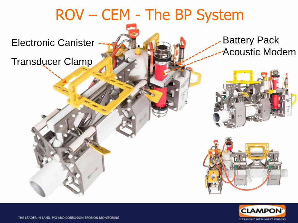
ROV – CEM - The BP System
Battery Pack
Acoustic Modem Electronic Canister
Transducer Clamp

ULTRASONIC INTELLIGENT SENSORS
Natural Energy
Conversion Enables
Sustained Unmanned
Ocean Operations
Proven platform with
Over 150K combined miles
At Sea
Uploading CEM data takes
approx. 3 minutes / month
Image courtesy of Liquid Robotics Oil+Gas

ULTRASONIC INTELLIGENT SENSORS
Data collection - Wave Gliders
• Monitors on every well • Acoustic link between CEM
and wave glider • Satellite link between
wave glider and office (web) • Data retrieval can be every
day

ULTRASONIC INTELLIGENT SENSORS

ULTRASONIC INTELLIGENT SENSORS
Data Harvesting via Acoustic Modem and
Satellite Radio and/or Broadband Wireless or
Cellular Link
Service multiple locations with one Wave Glider.
Acoustic Communications

ULTRASONIC INTELLIGENT SENSORS
One or more wave gliders will navigate the field relaying data from the equipment

ULTRASONIC INTELLIGENT SENSORS

ULTRASONIC INTELLIGENT SENSORS 34
Wave Glider Management System (WGMS)
Image courtesy of Liquid Robotics Oil+Gas

ULTRASONIC INTELLIGENT SENSORS Page
35
PacX CHALLENGE Unprecedented Journey of Marine Robots X the Pacific

ULTRASONIC INTELLIGENT SENSORS
22FT (6,7M) SEAS AND 50KT WINDS AT THE
ALASKA / CANADIAN BORDER
- Heavy Weather over 7 Days - As Part of a 3,500+ nmi Tour of the West Coast
Heavy Weather - US West Coast
Data courtesy of Liquid Robotics Oil+Gas

ULTRASONIC INTELLIGENT SENSORS
CEM Subsea
Corrosion-Erosion Monitor
- 3 Models alternatives for CEM -
- CEM for ROV installation
- CEM under insulation/coating
- CEM w/mechanical cover

ULTRASONIC INTELLIGENT SENSORS
Conclusion Clampon DSP Corrosion-Erosion Monitor
• Excellent correlation between measured and actual average thickness values, for a wide variety of defect types demonstrated with witness from independent observers (Shell, Statoil, BP, Hydro, Saudi Aramco, etc)
• Sensitivity of the CEM to changes in wall thickness demonstrated
• Generic defect, groove and pits were machined and detected
• Extremely high unevenness still gave far better results than initially predicted
• Robust nature of thickness evaluation method illustrated and monitored over a long time
• Temperature, flow is not affecting the Guided Waves
• Dry contact transducers have been developed to increase flexibility and stability of the CEM system
• Subsea CEM System qualification w/BP have been demonstrated.
• Tomography under development and very promising results providing MINIMUM wall thickness and location.

ULTRASONIC INTELLIGENT SENSORS
Thank you for your attention!
Any
questions?
www.ClampOn.com